

Page 1
SUN2000-(33KTL, 36KTL, 40KTL)-US
User Manual
Issue
01
Date
2017-04-01
HUAWEI TECHNOLOGIES CO., LTD.
Page 2

Issue 01 (2017-04-01)
Huawei Proprietary and Confidential
Copyright © Huawei Technologies Co., Ltd.
i
Copyright © Huawei Technologies Co., Ltd. 2017. All rights reserved.
No part of this document may be reproduced or transmitted in any form or by any means without prior
written consent of Huawei Technologies Co., Ltd.
Trademarks and Permissions
and other Huawei trademarks are trademarks of Huawei Technologies Co., Ltd.
All other trademarks and trade names mentioned in this document are the property of their respective
holders.
Notice
The purchased products, services and features are stipulated by the contract made between Huawei and
the customer. All or part of the products, services and features described in this document may not be
within the purchase scope or the usage scope. Unless otherwise specified in the contract, all statements,
information, and recommendations in this document are provided "AS IS" without warranties, guarantees or
representations of any kind, either express or implied.
The information in this document is subject to change without notice. Every effort has been made in the
preparation of this document to ensure accuracy of the contents, but all statements, information, and
recommendations in this document do not constitute a warranty of any kind, express or implied.
Huawei Technologies Co., Ltd.
Address:
Huawei Industrial Base
Bantian, Longgang
Shenzhen 518129
People's Republic of China
Website:
http://www.huawei.com
Email:
Page 3
SUN2000-(33KTL, 36KTL, 40KTL)-US
User Manual
About This Document
Issue 01 (2017-04-01)
Huawei Proprietary and Confidential
Copyright © Huawei Technologies Co., Ltd.
ii
Purpose
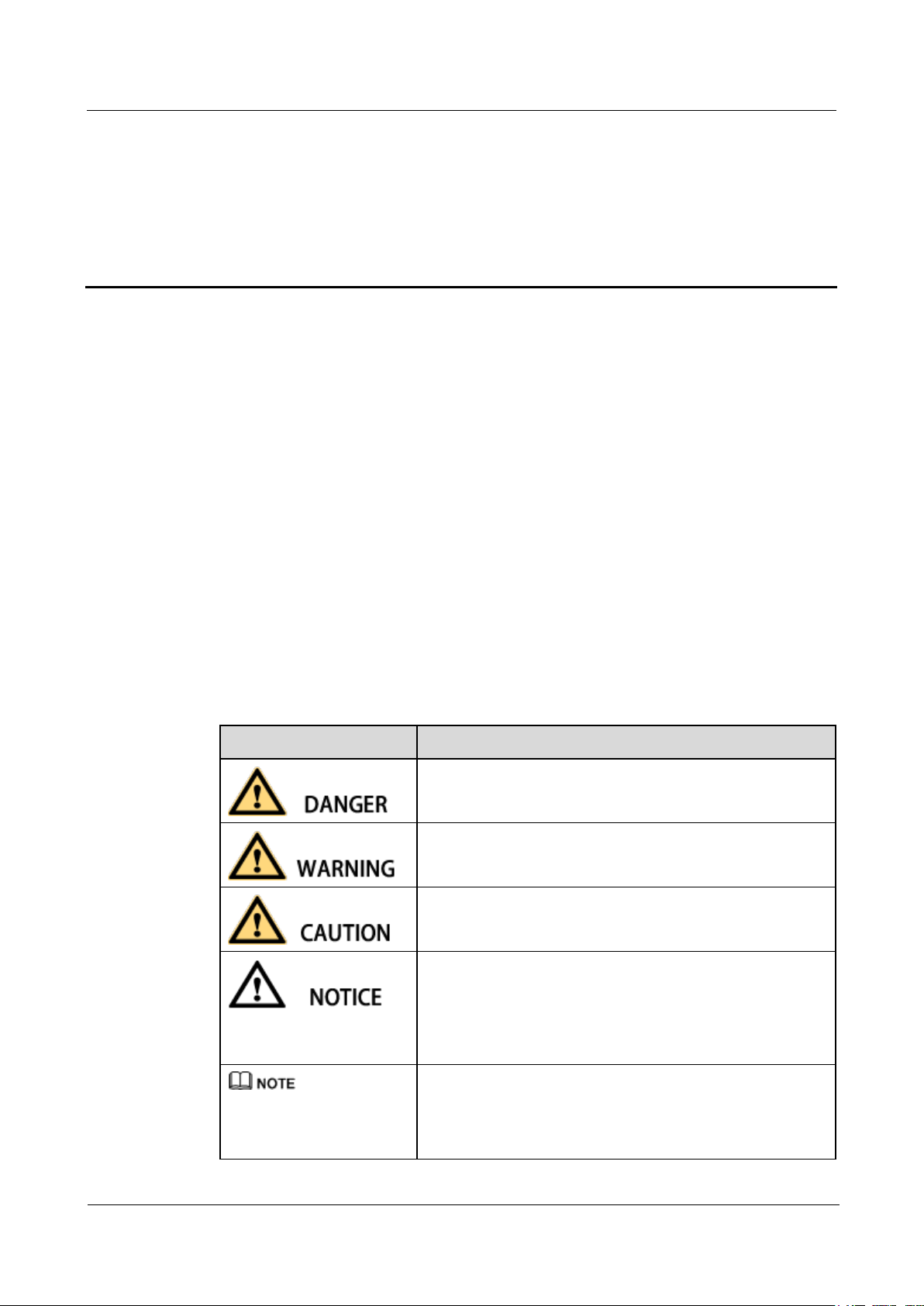
Symbol
Description
Indicates an imminently hazardous situation which, if not
avoided, will result in serious injury or death.
Indicates a potentially hazardous situation which, if not
avoided, could result in serious injury or death.
Indicates a potentially hazardous situation which, if not
avoided, may result in minor or moderate injury.
Indicates a potentially hazardous situation which, if not
avoided, could result in equipment damage, data loss,
performance deterioration, or unanticipated results.
NOTICE is used to address practices not related to personal
injury.
Calls attention to important information, best practices and
tips.
NOTE is used to address information not related to personal
injury, equipment damage, and environment deterioration.
This document describes the SUN2000-33KTL-US/36KTL-US/40KTL-US (SUN2000 for
short) in terms of its installation, electrical connections, commissioning, maintenance, and
troubleshooting. Understand the safety information and get familiar with the SUN2000
functions and features before installing and operating the SUN2000.
Intended Audience
About This Document
This document is intended for photovoltaic (PV) power plant personnel and qualified
electrical technicians.
Symbol Conventions
The symbols that may be found in this document are defined as follows.
Page 4

SUN2000-(33KTL, 36KTL, 40KTL)-US
User Manual
About This Document
Issue 01 (2017-04-01)
Huawei Proprietary and Confidential
Copyright © Huawei Technologies Co., Ltd.
iii
Change History
Changes between document issues are cumulative. The latest document issue contains all
updates made in previous issues.
Issue 01 (2017-04-01)
This issue is the first official release.
Page 5

SUN2000-(33KTL, 36KTL, 40KTL)-US
User Manual
Contents
Issue 01 (2017-04-01)
Huawei Proprietary and Confidential
Copyright © Huawei Technologies Co., Ltd.
iv
Contents
About This Document .................................................................................................................... ii
1 Safety Precautions ......................................................................................................................... 1
2 Overview ......................................................................................................................................... 4
2.1 Product Overview ......................................................................................................................................................... 4
2.2 Appearance ................................................................................................................................................................... 6
2.3 Label Description ........................................................................................................................................................ 10
2.4 Working Principle ....................................................................................................................................................... 14
3 SUN2000 Storage ......................................................................................................................... 16
4 System Installation ..................................................................................................................... 17
4.1 Checking Before Installation ...................................................................................................................................... 17
4.2 Tools ........................................................................................................................................................................... 18
4.3 Determining the Installation Position ......................................................................................................................... 22
4.4 Moving the Inverter .................................................................................................................................................... 27
4.5 Installing the Mounting Plate ...................................................................................................................................... 27
4.5.1 Wall-mounted Installation ........................................................................................................................................ 28
4.5.2 Common Support-mounted Installation ................................................................................................................... 31
4.5.3 Tilted Support-mounted Installation ........................................................................................................................ 33
4.6 Installing the SUN2000 .............................................................................................................................................. 34
5 Connecting Cables ...................................................................................................................... 38
5.1 Preparing OT Terminals .............................................................................................................................................. 38
5.2 Connecting the Ground Cable ..................................................................................................................................... 39
5.2.1 Grounding the SUN2000 over a PE Point ............................................................................................................... 40
5.2.2 PV Side Grounding .................................................................................................................................................. 41
5.3 Opening the Maintenance Compartment Door ........................................................................................................... 42
5.4 Connecting AC Output Power Cables ......................................................................................................................... 44
5.4.1 Connection Through a Pipe ..................................................................................................................................... 45
5.4.2 Common Connection ............................................................................................................................................... 51
5.5 (Optional) Installing the DC Protection Shroud ......................................................................................................... 57
5.6 Connecting DC Input Power Cables ........................................................................................................................... 59
5.7 Connecting Communications Cables .......................................................................................................................... 66
5.7.1 Communication Mode Description .......................................................................................................................... 66
Page 6

SUN2000-(33KTL, 36KTL, 40KTL)-US
User Manual
Contents
Issue 01 (2017-04-01)
Huawei Proprietary and Confidential
Copyright © Huawei Technologies Co., Ltd.
v
5.7.2 Selecting a Mode for Connecting RS485 Communications Cables ......................................................................... 67
5.7.3 Connecting RS485 Communications Cables Through a Pipe .................................................................................. 70
5.7.4 Connecting the RS485 Communications Cable in a Common Way ........................................................................ 75
5.8 Closing the Maintenance Compartment Door ............................................................................................................ 79
6 System Commissioning ............................................................................................................. 82
6.1 Checking Before Power-On ........................................................................................................................................ 82
6.2 Powering On the SUN2000 ........................................................................................................................................ 82
6.3 Powering Off the SUN2000 ........................................................................................................................................ 88
7 Man-Machine Interactions ........................................................................................................ 90
7.1 Operations with a USB Flash Drive............................................................................................................................ 90
7.1.1 Exporting Configurations ........................................................................................................................................ 90
7.1.2 Importing Configurations ........................................................................................................................................ 92
7.1.3 Exporting Data ......................................................................................................................................................... 93
7.1.4 Upgrading ................................................................................................................................................................ 94
7.2 Operations with a SmartLogger .................................................................................................................................. 96
7.3 Operations with the NMS ........................................................................................................................................... 96
7.4 Operations with the SUN2000 APP ............................................................................................................................ 96
8 Maintenance ................................................................................................................................. 97
8.1 Routine Maintenance ................................................................ ................................................................ .................. 97
8.2 Troubleshooting .......................................................................................................................................................... 98
9 Handling the SUN2000 ............................................................................................................ 105
9.1 Removing the SUN2000 ........................................................................................................................................... 105
9.2 Packing the SUN2000 ............................................................................................................................................... 105
9.3 Disposing of the SUN2000 ................................................................................................................................ ....... 105
10 Technical Specifications ........................................................................................................ 106
A Grid Codes................................................................................................................................. 110
B Acronyms and Abbreviations ................................................................................................ 111
Page 7

SUN2000-(33KTL, 36KTL, 40KTL)-US
User Manual
1 Safety Precautions
Issue 01 (2017-04-01)
Huawei Proprietary and Confidential
Copyright © Huawei Technologies Co., Ltd.
1
1 Safety Precautions
Before performing operations, read through this manual and follow all the precautions to
prevent accidents. The safety precautions provided in this document do not cover all the
safety precautions. Huawei shall not be liable for any consequence caused by the violation of
the safety operation regulations and design, production, and usage standards.
Declare
Huawei shall not be liable for any consequence caused by any of the following events.
Transportation
The storage conditions do not meet the requirements specified in this document.
Violate the operation instructions and safety precautions in this document for installation,
cable connecting, and maintenance.
Operation in extreme environments which are not covered in this document
Unauthorized modifications to the product or software code
Installation or use in environments which are not specified in related international
standards
Important Safety Instructions
Save These Instructions: This manual contains important instructions for the
SUN2000-33KTL-US/36KTL-US/40KTL-US that shall be followed during installation and
maintenance of the SUN2000.
Caution: Changes or modifications not expressly approved by the party responsible for
compliance could void the user's authority to operate the equipment.
Personnel Requirements
Only qualified electrical technicians are allowed to install and operate the SUN2000.
Operation personnel should receive professional training.
Page 8

SUN2000-(33KTL, 36KTL, 40KTL)-US
User Manual
1 Safety Precautions
Issue 01 (2017-04-01)
Huawei Proprietary and Confidential
Copyright © Huawei Technologies Co., Ltd.
2
Sign Protection
Installation
Operation personnel should read through this document and follow all the precautions.
Operation personnel should be familiar with the safety specifications about the electrical
system.
Operation personnel should understand the composition and working principles of the
grid-tied PV power system and local regulations.
Do not tamper with any warning signs on the SUN2000 chassis because these signs
contain important information about safe operation.
Do not tamper with the nameplate on the SUN2000 chassis because it contains important
product information.
Do not remove the warranty label from the SUN2000 chassis. Otherwise, product
warranty will be forfeited.
Ensure that the SUN2000 is not connected to a power supply and is not powered on
before starting installation.
Ensure that there are no objects within 300 mm (11.81 in.), 200 mm (7.87 in.), 500 mm
(19.69 in.), 600 mm (23.62 in.), and 1000 mm (39.37 in.) of the left, right, top, bottom,
and front of the SUN2000, respectively. This is to allow sufficient space for installation
and heat dissipation. For ease of installation, ensure that the SUN2000 bottom is at most
730 mm (28.74 in.) from the ground. If you have any questions about the distance,
consult the local technical support engineers.
Ensure that the SUN2000 is installed in a well ventilated environment.
Ensure that the SUN2000 heat sinks are free from blockage.
Open the maintenance compartment door of the chassis before connecting cables. Do not
perform any operation on other components inside the chassis except connecting AC
power cables and communications cables.
Cable Connections
Before connecting cables, ensure that the SUN2000 is securely positioned and not damaged in
any way. Otherwise, electric shocks or fire may occur.
Ensure that all electrical connections comply with local electrical standards.
Obtain approval from the local power supply department before using the SUN2000 to
generate electricity in grid-tied mode.
Ensure that the cables used in a grid-tied PV power system are properly connected and
insulated and meet specifications.
Operation
Page 9
SUN2000-(33KTL, 36KTL, 40KTL)-US
User Manual
1 Safety Precautions
Issue 01 (2017-04-01)
Huawei Proprietary and Confidential
Copyright © Huawei Technologies Co., Ltd.
3
High voltages may cause electric shocks and serious injuries during SUN2000 operating.
Strictly comply with the safety precautions in this document and associated documents when
operating the SUN2000.
Do not touch an operating SUN2000 because the heat sinks may have a temperature over
60°C (140°F) and may cause burns when the SUN2000 is operating.
Follow local laws and regulations when operating the equipment.
Maintenance and Replacement
High voltages may cause electric shocks and serious injuries during SUN2000 operating.
Therefore, before maintenance, power off the SUN2000 and strictly comply with the safety
precautions in this document and associated documents to operate the SUN2000.
Maintain the SUN2000 with sufficient knowledge of this document and proper tools and
testing equipment.
Before performing maintenance tasks, power off the SUN2000 and wait at least 5
minutes.
Place temporary warning signs or erect fences to prevent unauthorized access to the
maintenance site.
Rectify any faults that may compromise the SUN2000 security performance before
powering on the SUN2000 again.
Observe ESD precautions during the maintenance.
For personal safety, wear insulation gloves and protective shoes.
Page 10
SUN2000-(33KTL, 36KTL, 40KTL)-US
User Manual
2 Overview
Issue 01 (2017-04-01)
Huawei Proprietary and Confidential
Copyright © Huawei Technologies Co., Ltd.
4
2.1 Product Overview
Model
Rated Output Power
Rated Output Voltage
SUN2000-33KTL-US
33.3 kW
480 V
SUN2000-36KTL-US
36 kW
480 V
SUN2000-40KTL-US
40 kW
480 V
Function
The SUN2000 is a three-phase grid-tied PV string inverter that converts the DC power
generated by PV strings into AC power and feeds the power into the power grid.
2 Overview
Model
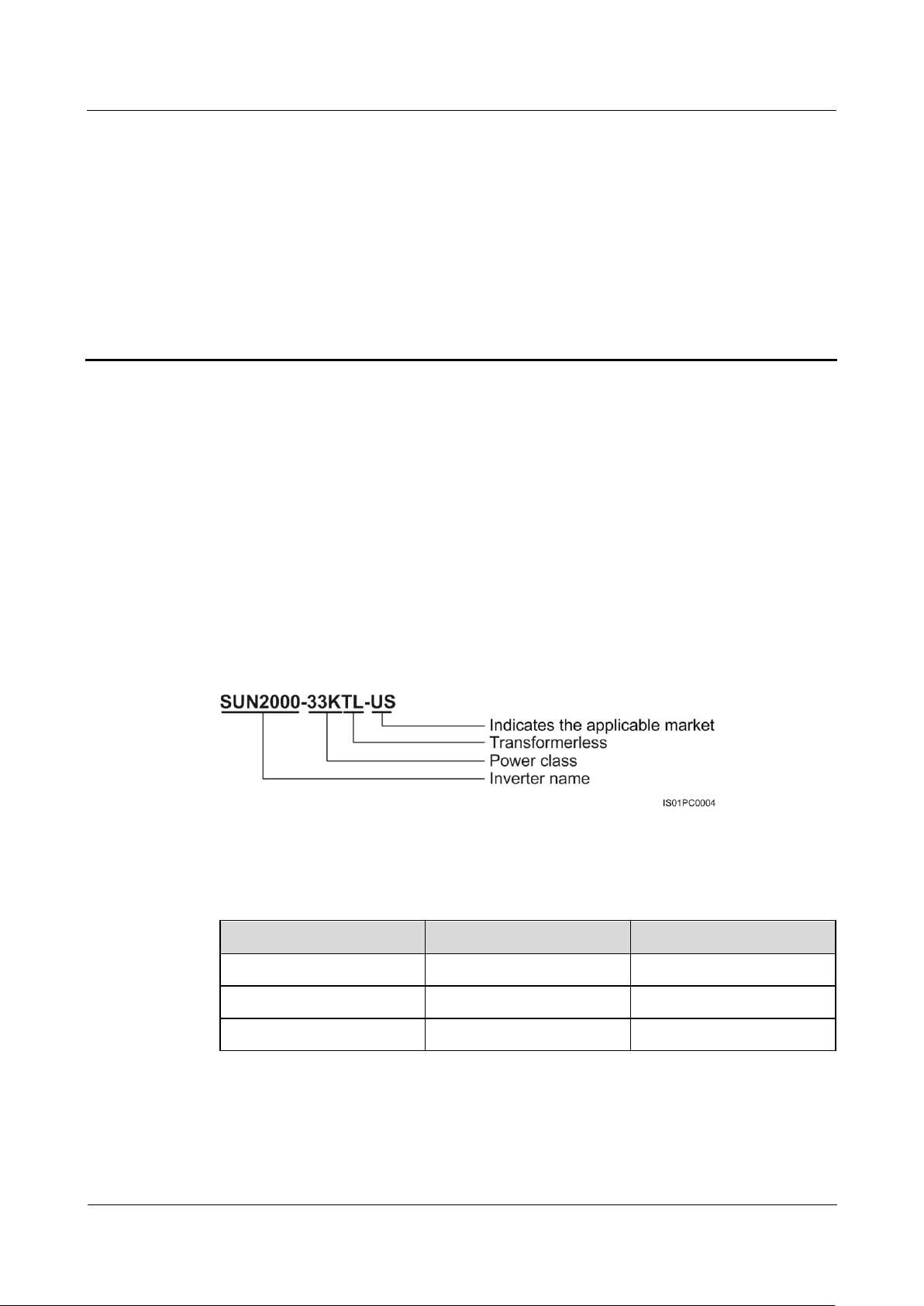
Figure 2-1 describes the model number of the SUN2000-33KTL-US.
Figure 2-1 Model number description
Table 2-1 describes the rated output power and voltage of all models of SUN2000s.
Table 2-1 SUN2000 models and corresponding rated output power and voltage
Page 11
SUN2000-(33KTL, 36KTL, 40KTL)-US
User Manual
2 Overview
Issue 01 (2017-04-01)
Huawei Proprietary and Confidential
Copyright © Huawei Technologies Co., Ltd.
5
Network Application
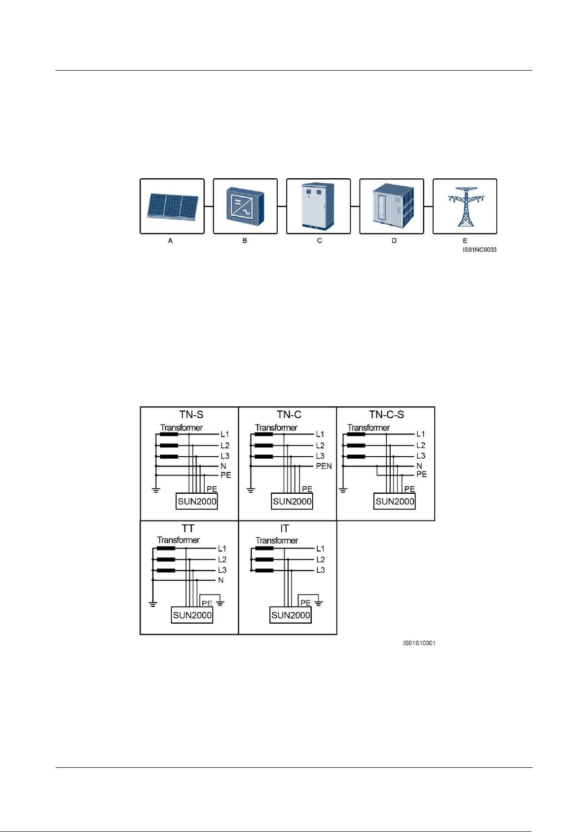
(A) PV string
(B) SUN2000
(C) ACDU
(D) Isolation transformer
(E) Power grid
The SUN2000 applies to grid-tied PV power systems for commercial rooftops and large
power stations. Typically, a grid-tied PV power system consists of PV strings, grid-tied
inverters, AC power distribution units, and isolation transformers.
Figure 2-2 Network application
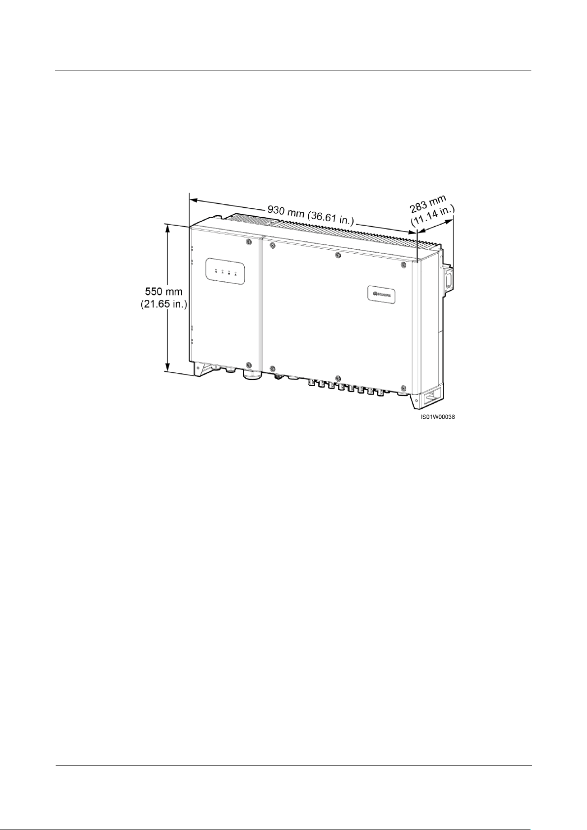
Power Grid Types
Power grid types supported by the SUN2000 include TN-S, TN-C, TN-C-S, TT, and IT.
Figure 2-3 Power grid types
Page 12
SUN2000-(33KTL, 36KTL, 40KTL)-US
User Manual
2 Overview
Issue 01 (2017-04-01)
Huawei Proprietary and Confidential
Copyright © Huawei Technologies Co., Ltd.
6
2.2 Appearance
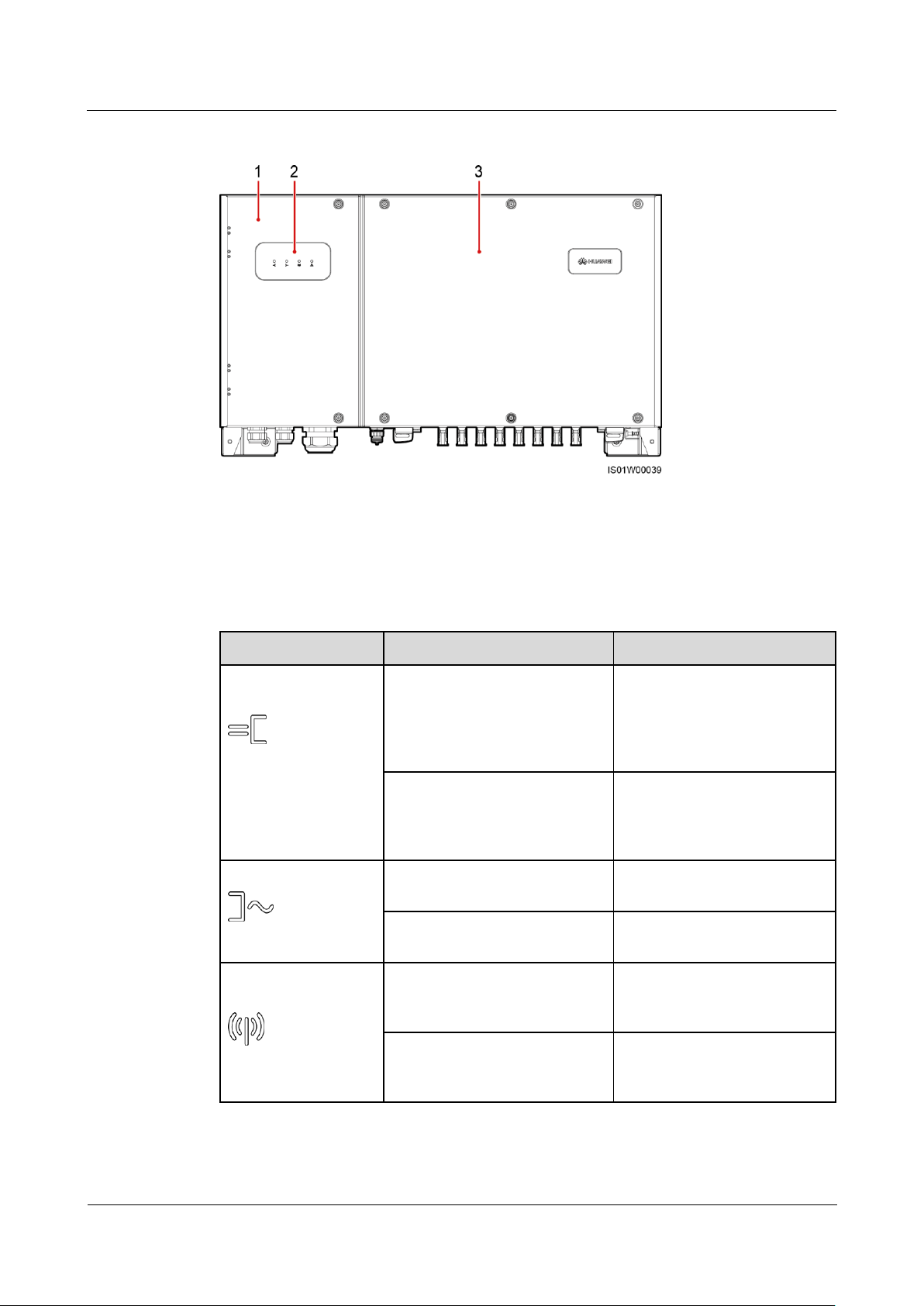
SUN2000 Dimensions
Figure 2-4 shows the SUN2000 dimensions.
Figure 2-4 SUN2000 dimensions (including the mounting plate)
Front View
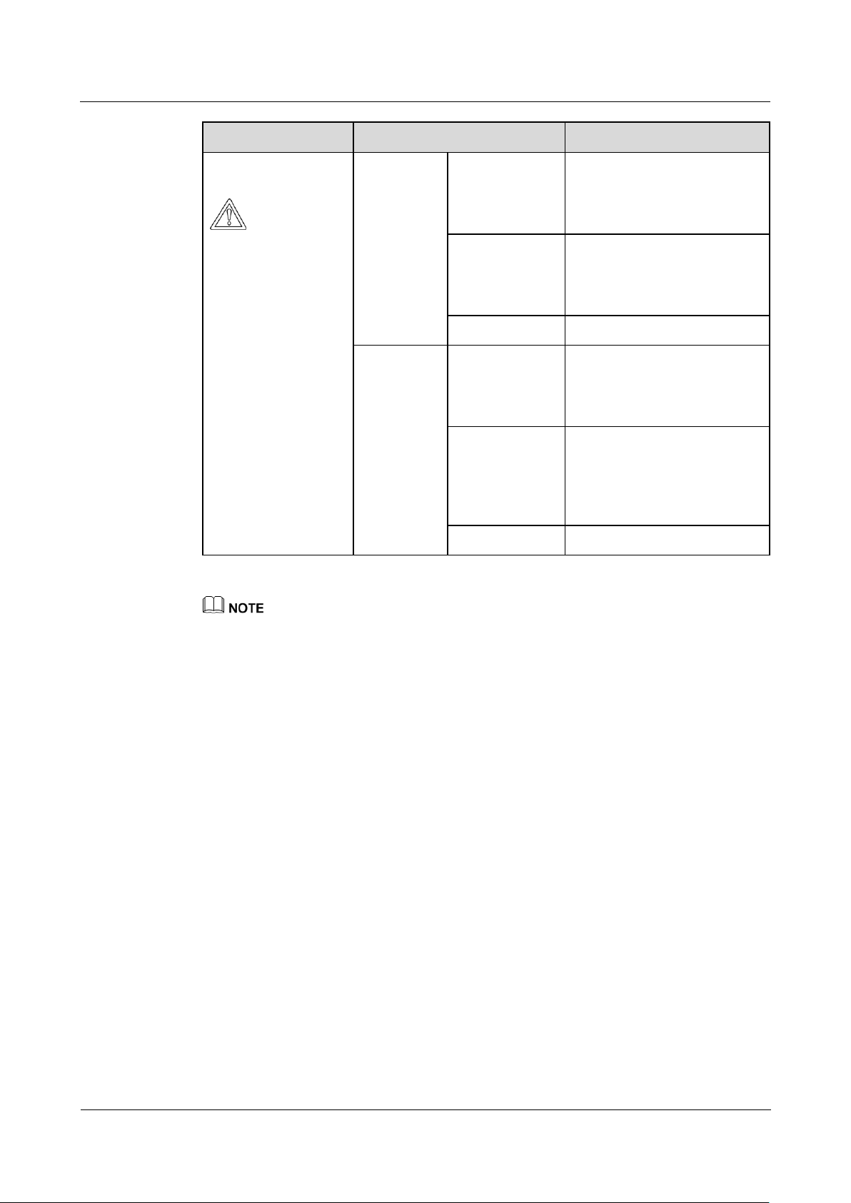
Figure 2-5 shows the SUN2000 front view.
Page 13
SUN2000-(33KTL, 36KTL, 40KTL)-US
User Manual
2 Overview
Issue 01 (2017-04-01)
Huawei Proprietary and Confidential
Copyright © Huawei Technologies Co., Ltd.
7
Figure 2-5 SUN2000 front view
(1) Maintenance compartment door
(2) LED indicator
(3) Host panel
Indicator
Status
Meaning
PV connection
indicator
Green on
At least one PV string is
properly connected, and the
DC input voltage of the
corresponding MPPT circuit is
higher than or equal to 200 V.
Green off
The SUN2000 disconnects
from all PV strings, or the DC
input voltage of each MPPT
circuit is less than 200 V.
Grid-tied indicator
Green on
The SUN2000 connects to the
power grid.
Green off
The SUN2000 does not
connect to the power grid.
Communications
indicator
Blinking green at short intervals
(on for 0.5s and then off for
0.5s)
The SUN2000 receives data
over RS485/PLC
communication.
Green off
The SUN2000 has not received
data over RS485/PLC
communication for 10 seconds.
Table 2-2 describes the LED indicators.
Table 2-2 LED indicator description (from left to right)
Page 14
SUN2000-(33KTL, 36KTL, 40KTL)-US
User Manual
2 Overview
Issue 01 (2017-04-01)
Huawei Proprietary and Confidential
Copyright © Huawei Technologies Co., Ltd.
8
Indicator
Status
Meaning
Alarm/Maintenance
indicator
Alarm status
Blinking red at
long intervals
(on for 1s and
then off for 4s)
A warning alarm is generated.
Blinking red at
short intervals
(on for 0.5s and
then off for 0.5s)
A minor alarm is generated.
Steady red
A critical alarm is generated.
Local
maintenance
status
Blinking green
at long intervals
(on for 1s and
then off for 1s)
Local maintenance is in
progress.
Blinking green
at short intervals
(on for 0.125s
and then off for
0.125s)
Local maintenance fails.
Steady green
Local maintenance succeeds.
SUN2000 Rear View
Local maintenance refers to operations performed after a universal serial bus (USB) flash drive,
Bluetooth module, or USB data cable is inserted into the USB port of the SUN2000. For example,
local maintenance includes data import and export using a USB flash drive and connecting to the
SUN2000 APP over a Bluetooth module or USB data cable.
If alarming and local maintenance happen concurrently, the alarm/maintenance indicator shows the
local maintenance state first. After the USB flash drive, Bluetooth module, or USB data cable is
removed, the indicator shows the alarm state.
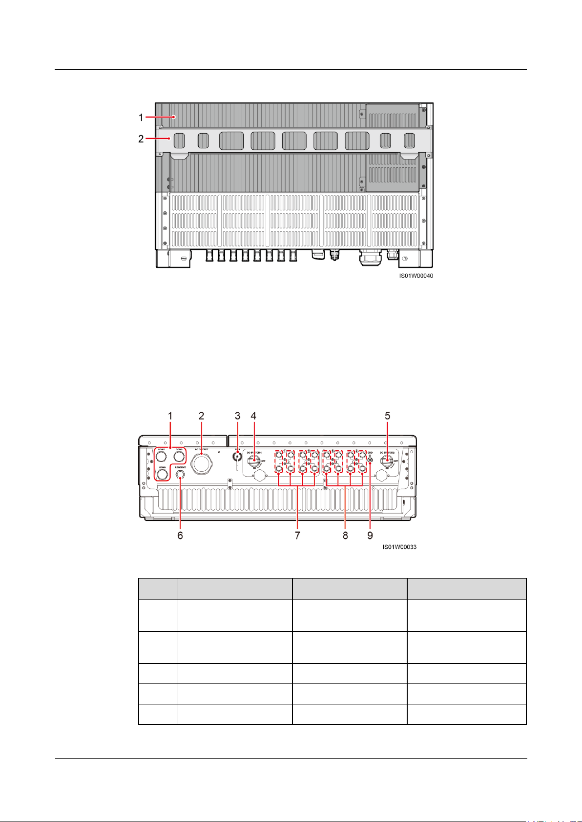
Figure 2-6 shows the SUN2000 rear view.
Page 15
SUN2000-(33KTL, 36KTL, 40KTL)-US
User Manual
2 Overview
Issue 01 (2017-04-01)
Huawei Proprietary and Confidential
Copyright © Huawei Technologies Co., Ltd.
9
Figure 2-6 SUN2000 rear view
(1) Heat sink
(2) Mounting plate
No.
Component
Description
Silk Screen
1
3/4-inch waterproof
cable connector
Inner diameter: 14–18
mm (0.55–0.71 in.)
COM1, COM2, COM3
2
2-inch waterproof cable
connector
Inner diameter: 37–44
mm (1.46–1.73 in.)
AC OUTPUT
3
USB port
N/A
USB
4
DC switch 1
N/A
DC SWITCH 1
5
DC switch 2
N/A
DC SWITCH 2
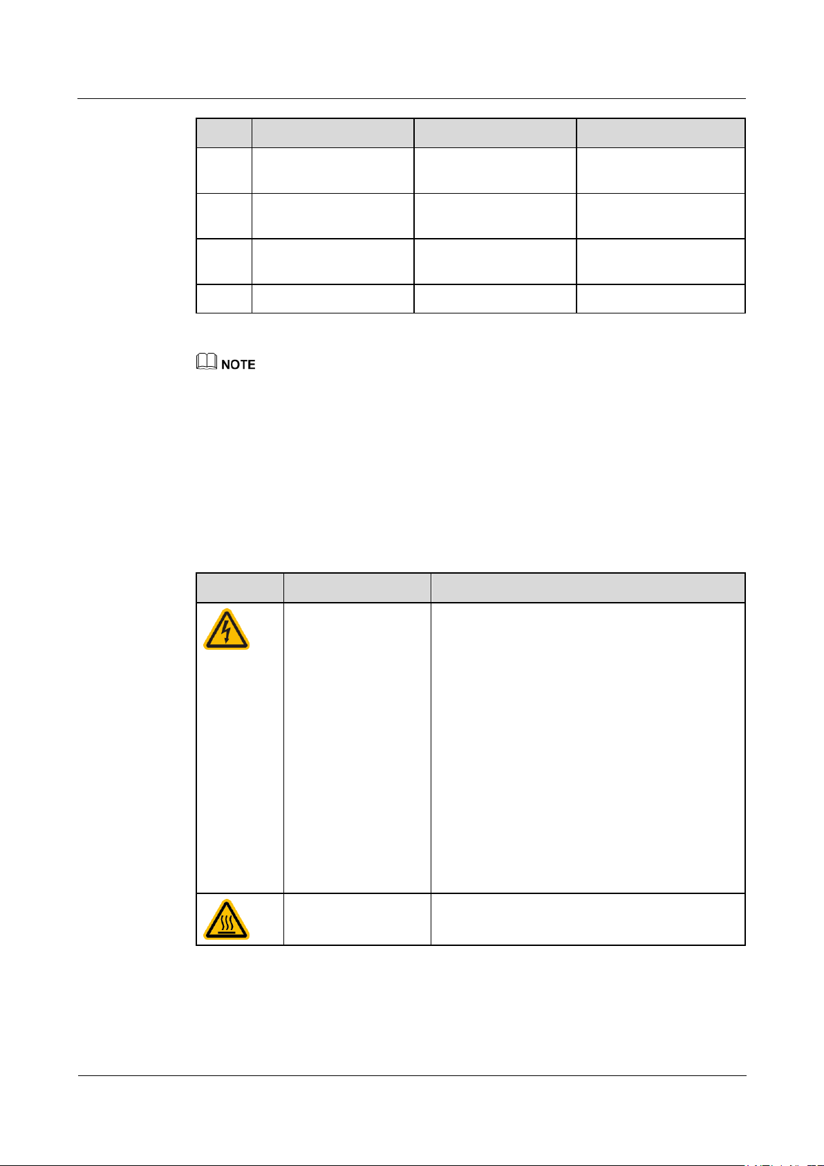
SUN2000 bottom view
Figure 2-7 shows the SUN2000 bottom view.
Figure 2-7 SUN2000 bottom view
Page 16
SUN2000-(33KTL, 36KTL, 40KTL)-US
User Manual
2 Overview
Issue 01 (2017-04-01)
Huawei Proprietary and Confidential
Copyright © Huawei Technologies Co., Ltd.
10
No.
Component
Description
Silk Screen
6
1/2-inch waterproof
cable connector
Inner diameter: 6–12
mm (0.24–0.47 in.)
RESERVE
7
DC input terminal
Controlled by DC
SWITCH 1
+/–
8
DC input terminal
Controlled by DC
SWITCH 2
+/–
9
PV side ground point
N/A
GND
Symbol
Name
Meaning
Electric shock
Lethal voltages 1000 V DC. Keep out.
No user serviceable parts inside. Only trained
service personnel are allowed access.
Both AC and DC voltage sources are
terminated inside this equipment. Each circuit
must be disconnected before servicing.
When the photovoltaic array is exposed to light,
it supplies DC voltage to this equipment.
The DC conductors of this photovoltaic system
are ungrounded and may be energized.
The DC conductors of this photovoltaic system
are normally ungrounded but will become
intermittently grounded without indication
when the SUN2000 measures the PV array
isolation.
Burn warning
Do not touch a running SUN2000 because it
generates high temperatures on the shell.
Waterproof cable connector is abbreviated as waterproof connector in the following text.
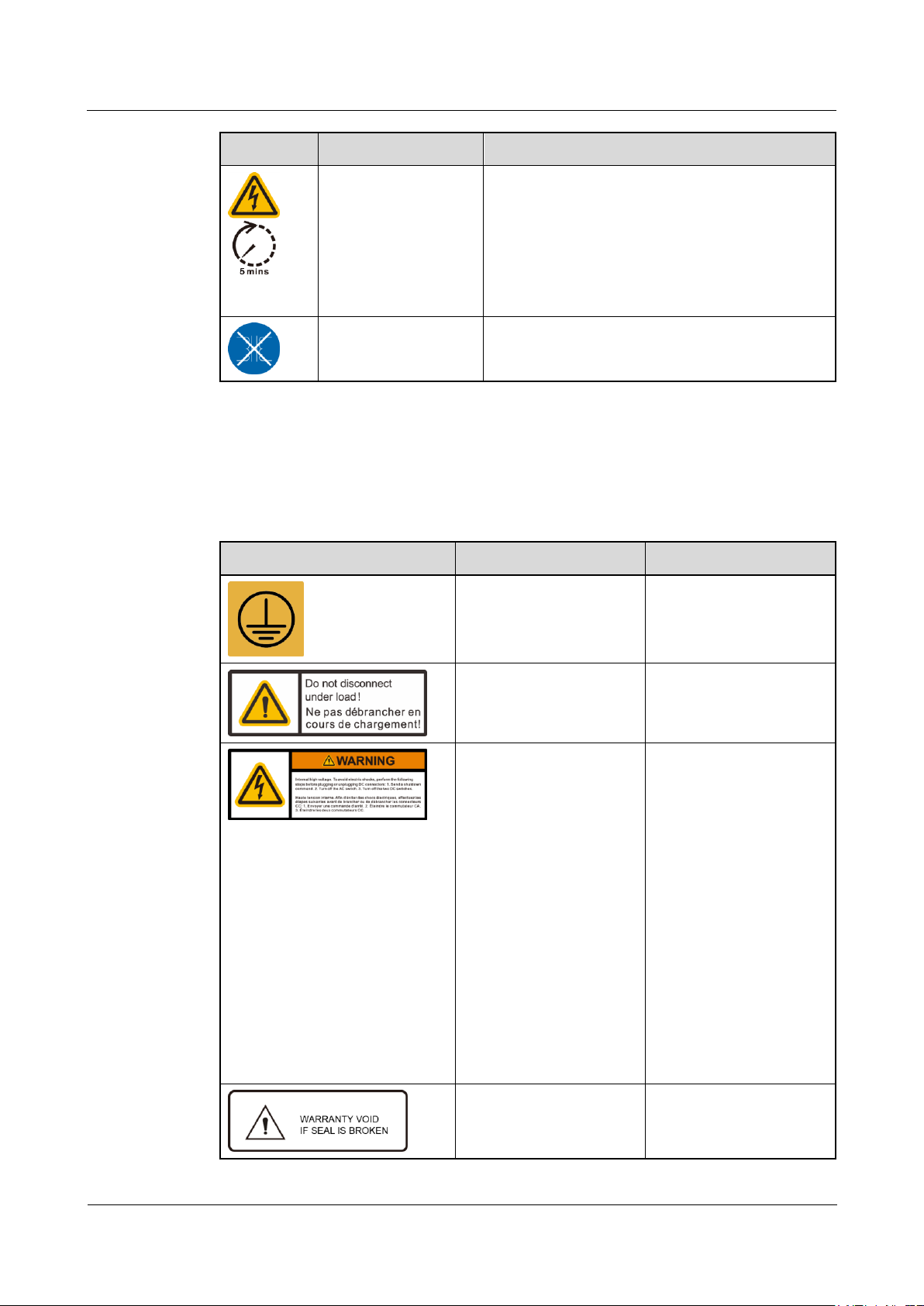
2.3 Label Description
Warning Signs
Warning signs are available on the SUN2000 side, as described in Table 2-3.
Table 2-3 Warning signs
Page 17
SUN2000-(33KTL, 36KTL, 40KTL)-US
User Manual
2 Overview
Issue 01 (2017-04-01)
Huawei Proprietary and Confidential
Copyright © Huawei Technologies Co., Ltd.
11
Symbol
Name
Meaning
Delay discharge
High voltage exists after the SUN2000 is
powered on. Only qualified and trained
electrical technicians are allowed to perform
operations on the SUN2000.
Residual voltage exists after the SUN2000 is
powered off. It takes 5 minutes for the
SUN2000 to discharge to the safe voltage.
Transformerless
inverter
The SUN2000 output does not pass through an
isolation transformer.
Symbols
Symbol
Name
Meaning
PE point
Indicates the position for
connecting the PE cable.
Operation warning
Do not remove the DC
input connector when the
SUN2000 is running.
DC terminal operation
warninga
High voltage exists after
the SUN2000 is powered
on. To avoid electric
shocks, perform the
following system
power-off operations
before plugging or
unplugging DC input
connectors of the
SUN2000:
1. Send a shutdown
command.
2. Turn off the
downstream AC
switch.
3. Turn off the two DC
switches at the bottom.
Warranty label
Never open the host panel
of the SUN2000.
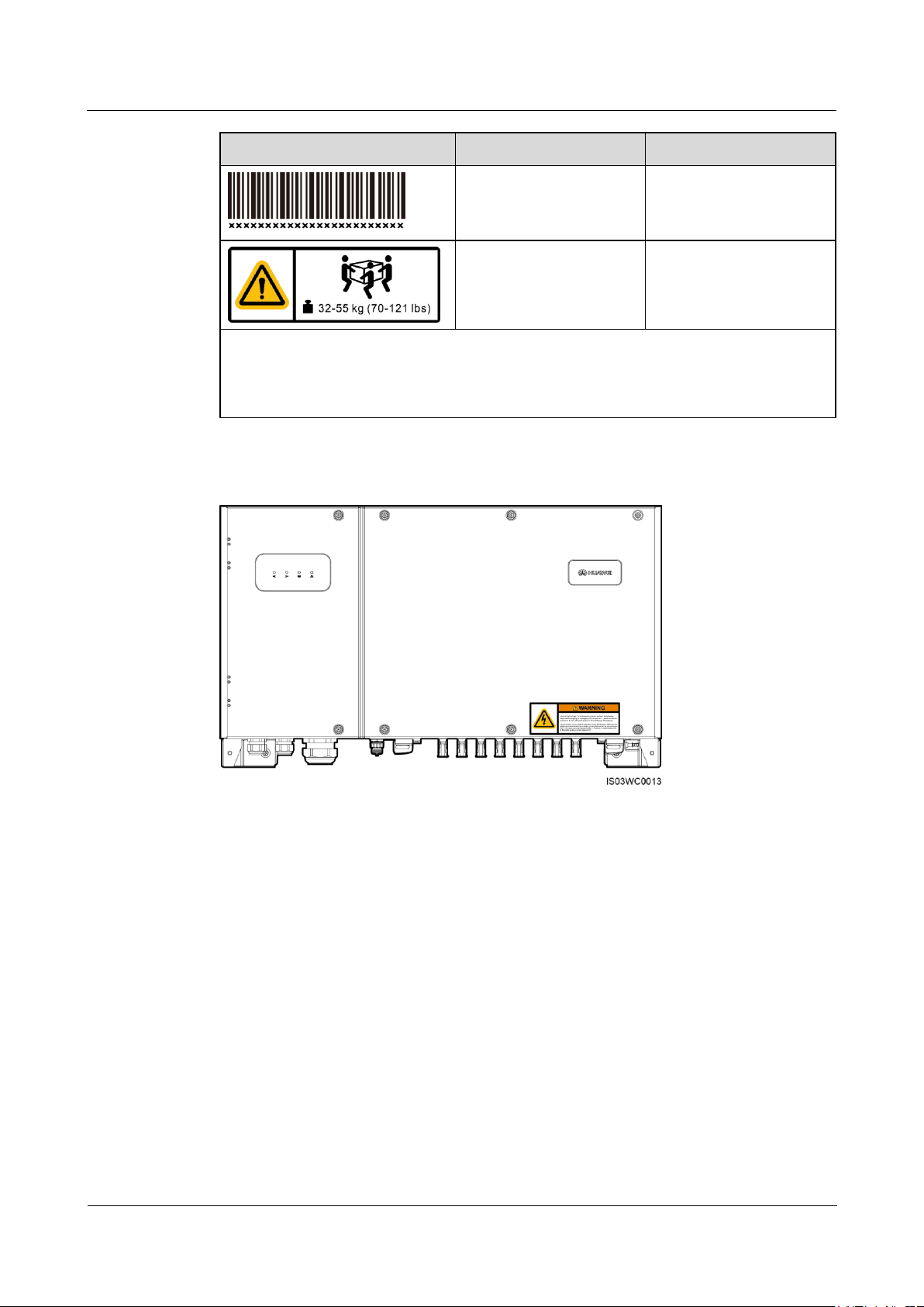
Table 2-4 describes the labels on the SUN2000 chassis and their meanings.
Table 2-4 Label description
Page 18
SUN2000-(33KTL, 36KTL, 40KTL)-US
User Manual
2 Overview
Issue 01 (2017-04-01)
Huawei Proprietary and Confidential
Copyright © Huawei Technologies Co., Ltd.
12
Symbol
Name
Meaning
SUN2000 serial number
label
Indicates the SUN2000
serial number.
Weight label
The SUN2000 is heavy
and needs to be carried by
multiple persons.
Note a: Fittings delivered with the SUN2000 contain the label of DC terminal operation
warning. You are advised to attach the label at the bottom of the SUN2000 front side, as
shown in Figure 2-8. You can also select an appropriate place for attaching the label based
on site requirements.
Figure 2-8 Place for attaching
Nameplate
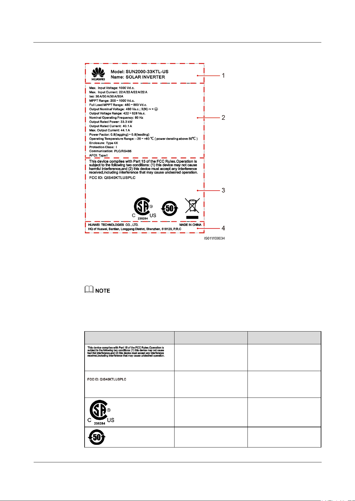
On the side of the SUN2000, there is a nameplate that contains the model information,
technical specifications, and compliance symbols, as shown in Figure 2-9.
Page 19
SUN2000-(33KTL, 36KTL, 40KTL)-US
User Manual
2 Overview
Issue 01 (2017-04-01)
Huawei Proprietary and Confidential
Copyright © Huawei Technologies Co., Ltd.
13
Figure 2-9 Nameplate of the SUN2000-33KTL-US
(1) Trademark and product model
(2) Important technical specifications
(3) Compliance symbols
(4) Company name and country of manufacture
Symbol
Name
Meaning
American FCC Part 15B
certification
The SUN2000 complies
with FCC Part 15B
certification standards.
American FCC Part 15G
certification
The SUN2000 complies
with FCC Part 15G
certification standards.
CSA certification of
America and Canada
The SUN2000 complies
with CSA certification
standards.
EFUP label
The SUN2000 does not
pollute the environment
The nameplate figure is for reference only. The actual nameplate prevails.
Table 2-5 describes the compliance symbols.
Table 2-5 Compliance symbols
Page 20
SUN2000-(33KTL, 36KTL, 40KTL)-US
User Manual
2 Overview
Issue 01 (2017-04-01)
Huawei Proprietary and Confidential
Copyright © Huawei Technologies Co., Ltd.
14
Symbol
Name
Meaning
during the specified
period.
WEEE label
Do not dispose of the
SUN2000 as household
garbage.
2.4 Working Principle
Conceptual Diagram
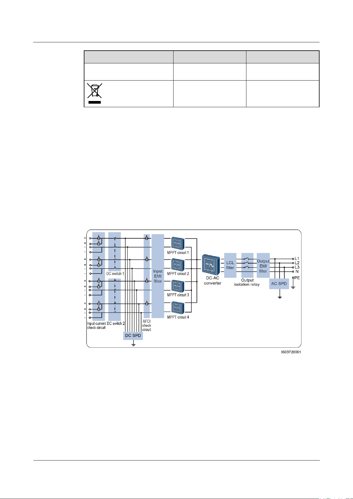
The SUN2000 receives inputs from eight PV strings. Then the inputs are grouped into four
MPPT routes inside the SUN2000 to track the maximum power point of the PV strings. The
DC power is then converted into three-phase AC power through an inverter circuit. Surge
protection is supported on both the DC and AC sides. Figure 2-10 shows the SUN2000
conceptual diagram.
Figure 2-10 SUN2000 conceptual diagram
Working Modes
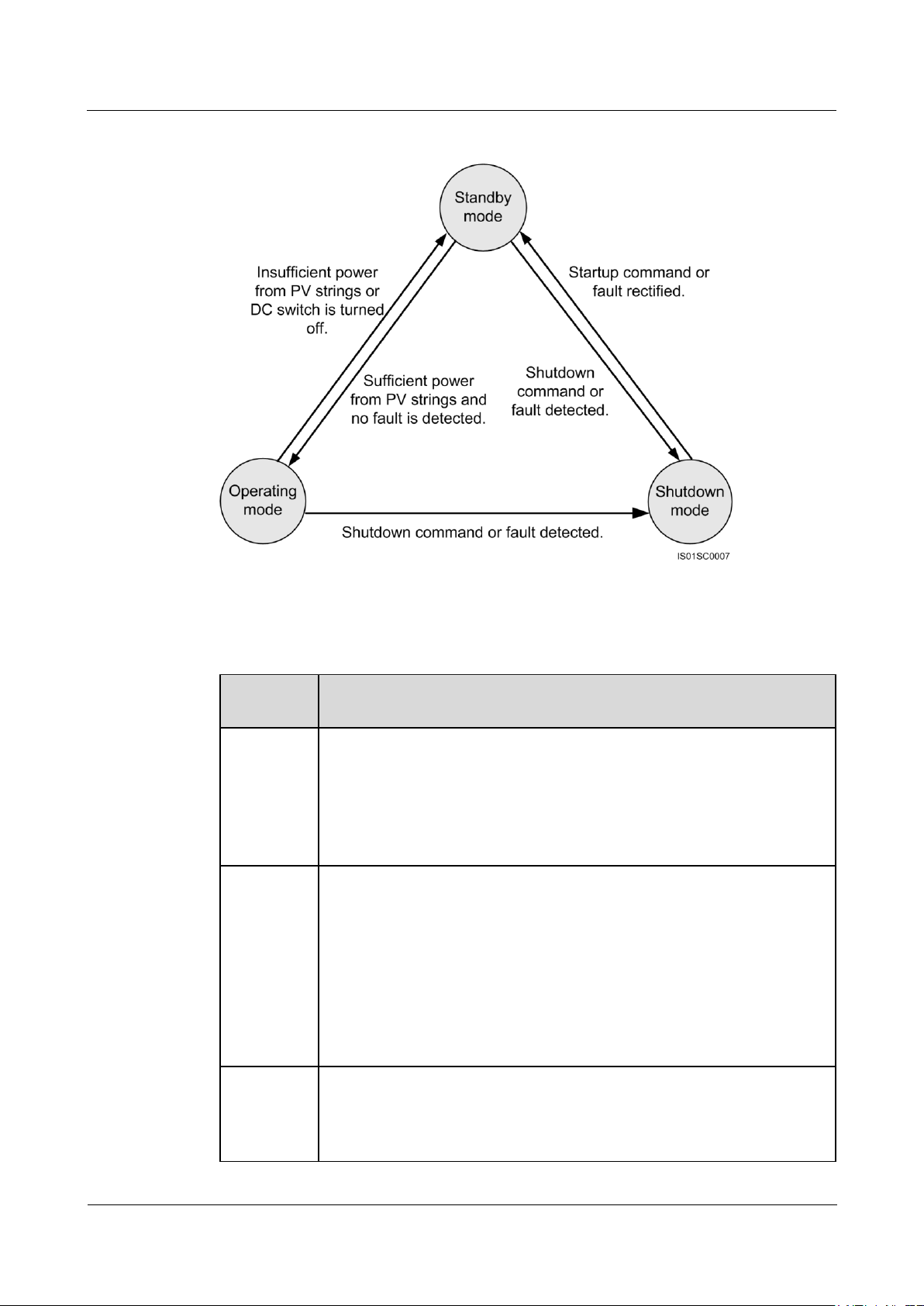
The SUN2000 can work in standby, operating, or shutdown mode. Figure 2-11 shows the
relationship between the three working modes.
Page 21
SUN2000-(33KTL, 36KTL, 40KTL)-US
User Manual
2 Overview
Issue 01 (2017-04-01)
Huawei Proprietary and Confidential
Copyright © Huawei Technologies Co., Ltd.
15
Figure 2-11 SUN2000 working modes
Working
Mode
Description
Standby
The SUN2000 enters the standby mode when the external environment does
not meet the requirements for starting the SUN2000. In standby mode:
The SUN2000 continuously performs self-check and enters the operating
mode once the operating requirements are met.
If the SUN2000 enters the shutdown mode after detecting a shutdown
command or a fault after startup.
Operating
In operating mode:
The SUN2000 converts DC power from PV strings into AC power and
feeds the power to the power grid.
The SUN2000 tracks the maximum power point to maximize the PV
string output.
The SUN2000 enters the shutdown mode after detecting a fault or a
shutdown command, and enters the standby mode after detecting that the
PV string output power does not meet the requirements for grid-tied
electricity generation.
Shutdown
In standby or operating mode, the SUN2000 enters the shutdown mode
after detecting a fault or shutdown command.
In shutdown mode, the SUN2000 enters the standby mode after detecting
a startup command or that a fault is rectified.
Table 2-6 describes the three working modes shown in Figure 2-11.
Table 2-6 Working mode description
Page 22

SUN2000-(33KTL, 36KTL, 40KTL)-US
User Manual
3 SUN2000 Storage
Issue 01 (2017-04-01)
Huawei Proprietary and Confidential
Copyright © Huawei Technologies Co., Ltd.
16
3 SUN2000 Storage
The following requirements should be met if the SUN2000 is not put into use directly:
Do not unpack the SUN2000.
Keep the storage temperature at –40°C to +70°C (–40°F to +158°F) and the humidity at
5%–100% RH.
The SUN2000 should be stored in a clean and dry place and be protected from dust and
water vapor corrosion.
A maximum of five SUN2000s can be stacked.
Periodic inspections are required during the storage. If any rodent bites are found,
replace the packing materials immediately.
If the SUN2000 has been long-term stored, inspections and tests should be conducted by
qualified personnel before it is put into use.
Page 23
SUN2000-(33KTL, 36KTL, 40KTL)-US
User Manual
4 System Installation
Issue 01 (2017-04-01)
Huawei Proprietary and Confidential
Copyright © Huawei Technologies Co., Ltd.
17
4 System Installation
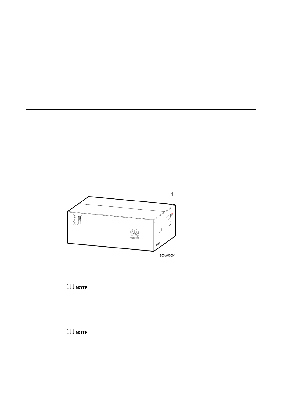
(1) Position of the model label
4.1 Checking Before Installation
Outer Packing Materials
Before unpacking the inverter, check the outer packing materials for damage, such as holes
and cracks, and check the inverter model. If any damage is found or the inverter model is not
what you requested, do not unpack the package and contact your supplier as soon as possible.
Figure 4-1 Position of the inverter model label
Package Contents
After unpacking the inverter, check that the contents are intact and complete. If any damage is
found or any component is missing, contact your supplier.
You are advised to remove the packing materials within 24 hours before installing the inverter.
For details about the number of contents, see the Packing List in the packing case.
Page 24
SUN2000-(33KTL, 36KTL, 40KTL)-US
User Manual
4 System Installation
Issue 01 (2017-04-01)
Huawei Proprietary and Confidential
Copyright © Huawei Technologies Co., Ltd.
18
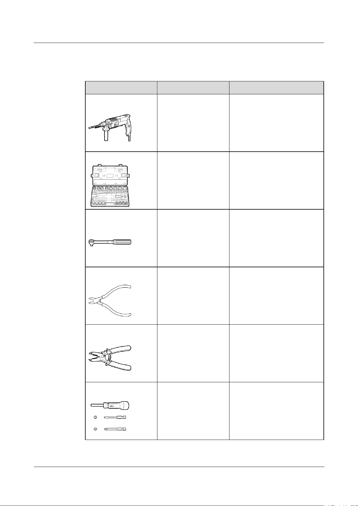
4.2 Tools
Tool
Model
Function
Hammer drill
Drill bit: Φ14 mm (0.54
in.) and Φ16 mm (0.63
in.)
Φ14 mm (0.54 in.) drill bit:
Drills holes in supports.
Φ16 mm (0.63 in.) drill bit:
Drills holes in walls.
Socket wrench set
Works with a torque
wrench.
Secures bolts and AC output
terminals.
Torque wrench
N/A
Secures bolts and AC output
terminals.
Diagonal pliers
N/A
Cut cable ties.
Wire stripper
N/A
Peels cable jackets.
Torque screwdriver
Flat head: M3
Phillips head: M4
Connects cables to the terminal
block.
Secure the AC filter.
Prepare tools required for installation and cable connections.
Page 25
SUN2000-(33KTL, 36KTL, 40KTL)-US
User Manual
4 System Installation
Issue 01 (2017-04-01)
Huawei Proprietary and Confidential
Copyright © Huawei Technologies Co., Ltd.
19
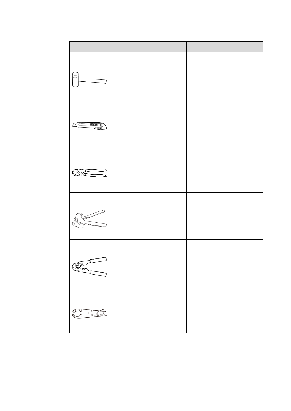
Tool
Model
Function
Rubber mallet
N/A
Hammers expansion bolts into
holes.
Utility knife
N/A
Removes packages.
Cable cutter
N/A
Cuts power cables.
Crimping tool
H4TC0001
Manufacturer:
AMPHENOL
Crimps metal terminals when
preparing DC input power cables.
RJ45 crimping tool
N/A
Prepares RJ45 connectors for
communications cables.
Removal tool
H4TW0001
Manufacturer:
AMPHENOL
Removes DC connectors from the
SUN2000.
Page 26
SUN2000-(33KTL, 36KTL, 40KTL)-US
User Manual
4 System Installation
Issue 01 (2017-04-01)
Huawei Proprietary and Confidential
Copyright © Huawei Technologies Co., Ltd.
20
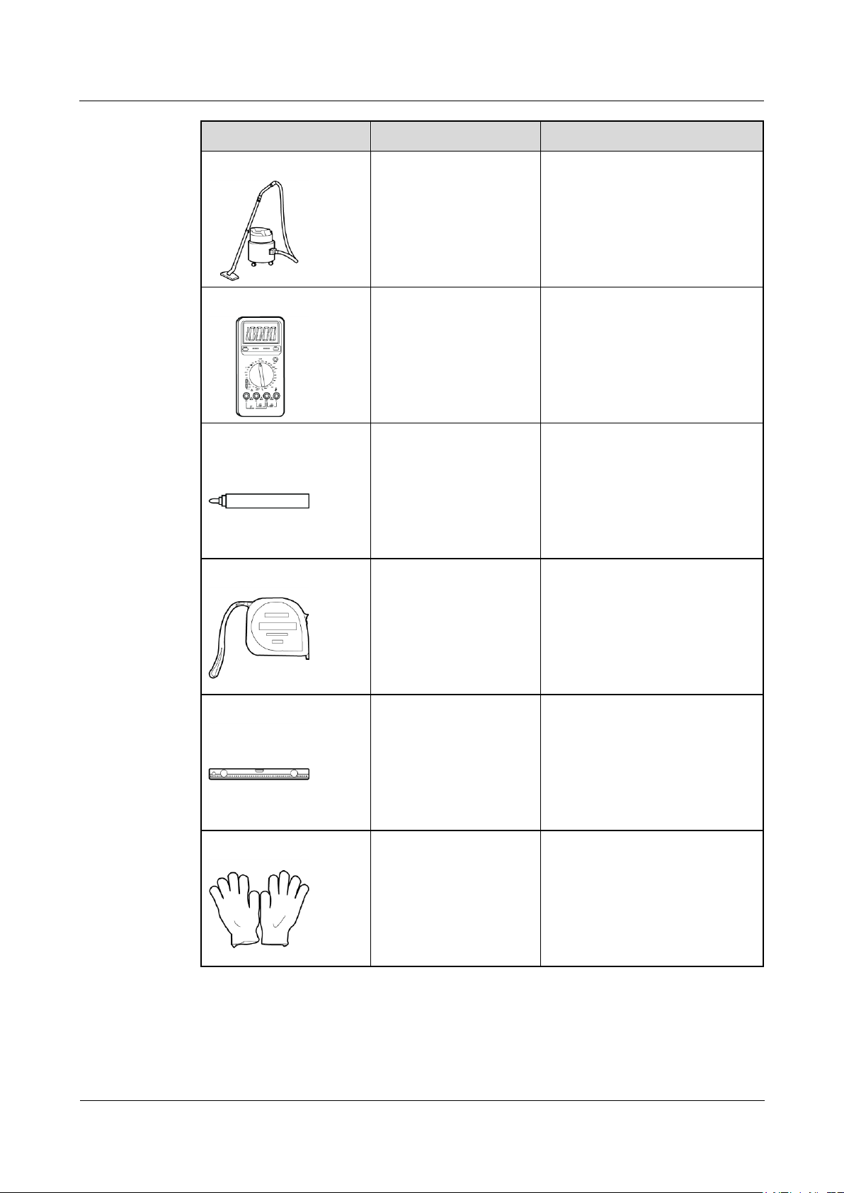
Tool
Model
Function
Vacuum cleaner
N/A
Cleans up dust after drilling holes.
Multimeter
DC voltage measurement
range ≥ 1000 V DC
Measures voltages.
Marker
N/A
Marks signs.
Measuring tape
N/A
Measures distances.
Level
N/A
Levels hole positions.
Protective gloves
N/A
Protect your hands during
installation.
Page 27
SUN2000-(33KTL, 36KTL, 40KTL)-US
User Manual
4 System Installation
Issue 01 (2017-04-01)
Huawei Proprietary and Confidential
Copyright © Huawei Technologies Co., Ltd.
21
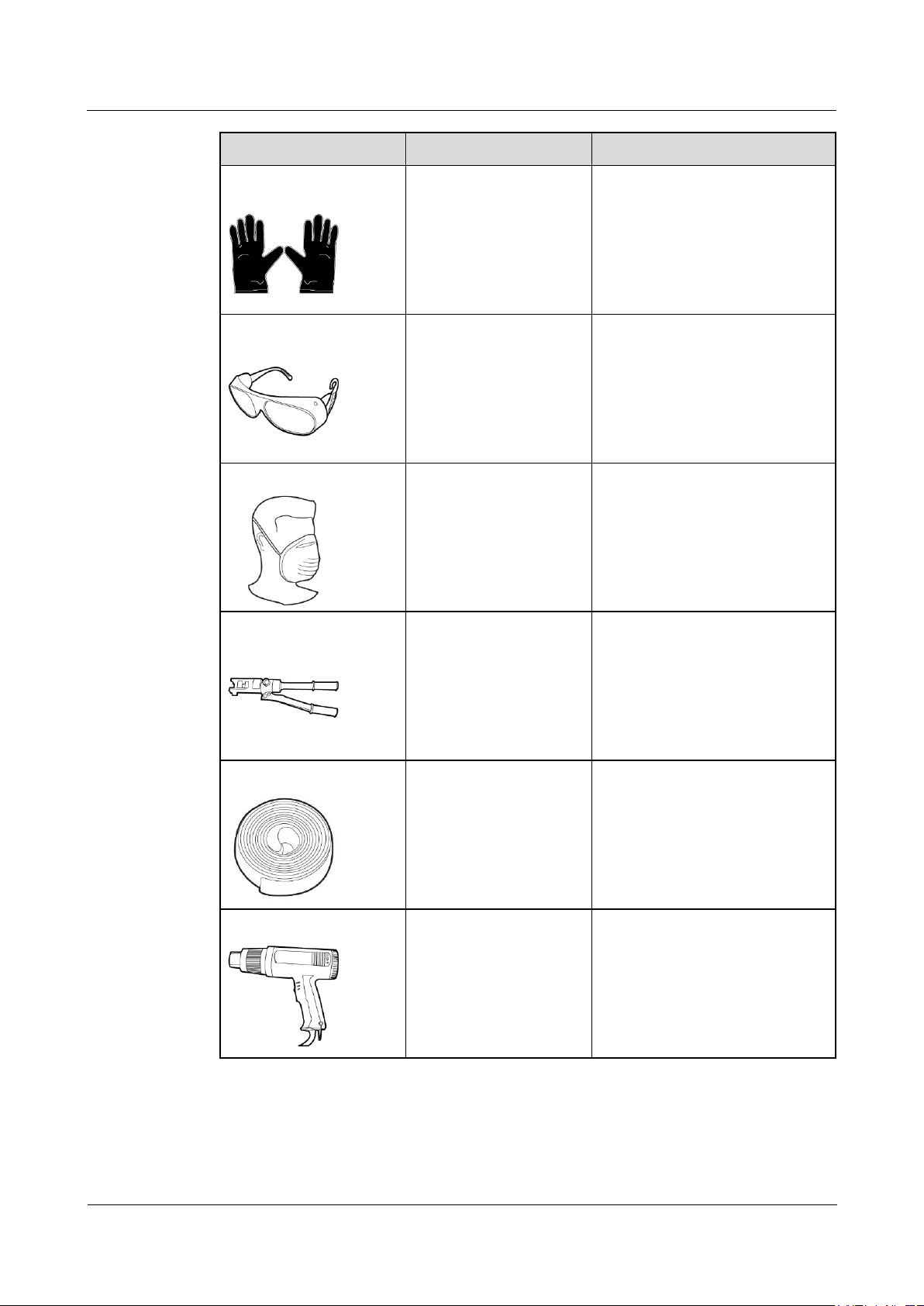
Tool
Model
Function
Insulation gloves
Operating voltage ≥ 2000
V
Protect you from electric shocks.
Safety goggles
N/A
Protect your eyes during hole
drilling.
Anti-dust respirator
N/A
Protects you from dust during hole
drilling.
Hydraulic pliers
N/A
Crimp OT terminals.
Heat shrink tubing
N/A
Wraps the cable crimping area of
an OT terminal.
Heat gun
N/A
Heat-shrinks a tube.
Page 28
SUN2000-(33KTL, 36KTL, 40KTL)-US
User Manual
4 System Installation
Issue 01 (2017-04-01)
Huawei Proprietary and Confidential
Copyright © Huawei Technologies Co., Ltd.
22
Tool
Model
Function
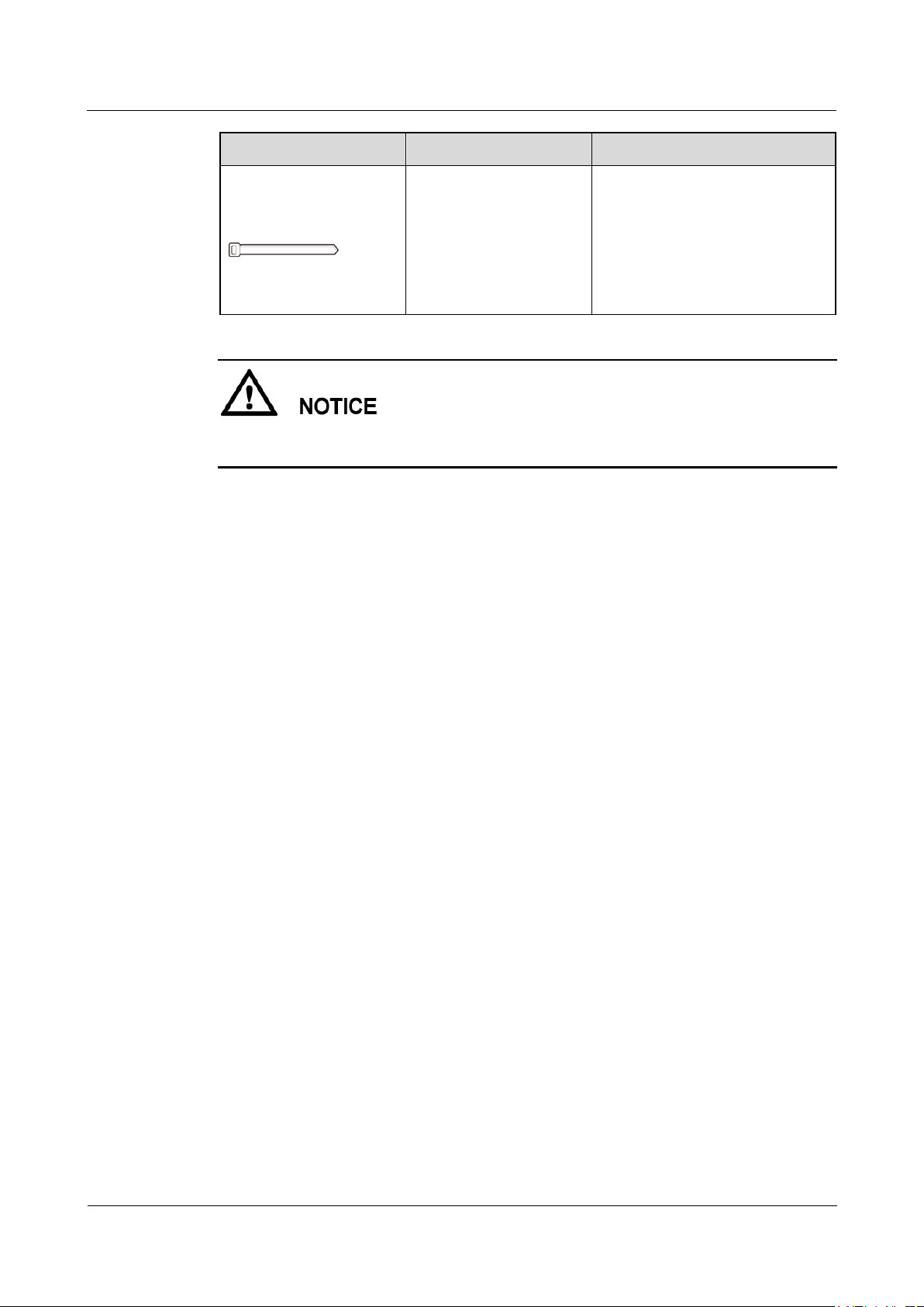
Cable tie
N/A
Binds cables.
Install devices in accordance with the installation laws and regulations of the country or
region where the project is located.
4.3 Determining the Installation Position
Basic Requirements
The SUN2000 is protected to Type 4X and can be installed indoors or outdoors.
Do not install the SUN2000 in a place where personnel are easy to come into contact
with its chassis and heat sinks, because these parts are extremely hot during operation.
Do not store the SUN2000 in areas with flammable or explosive materials.
Installation Environment Requirements
The SUN2000 must be installed in a well ventilated environment to ensure good heat
dissipation. When installed under direct sunlight, performance de-rate may be initiated due to
additional temperature rise.
Carrier Requirements
The carrier where the SUN2000 is installed must be fireproof.
Do not install the SUN2000 on flammable building materials.
The SUN2000 weighs 55 kg (121.25 lb). Ensure that installation surface is solid enough
to bear the SUN2000.
In residential areas, do not install the SUN2000 on gypsum boards or walls made of
similar materials which have a weak sound insulation performance because the noises
generated by the SUN2000 disturb residents.
Installation Angle Requirements
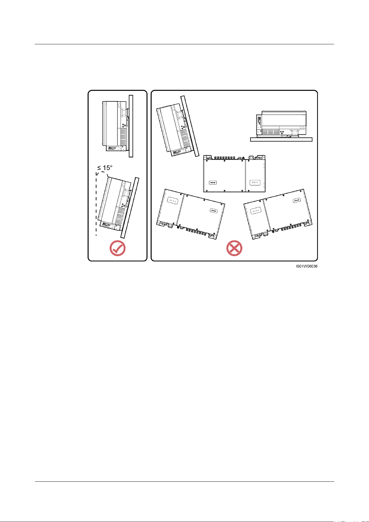
The SUN2000 can be installed on a wall, normal support, and tilted support.
Tilt requirements for installing a SUN2000 on a wall and normal support:
Install the SUN2000 vertically or at a maximum back tilt of 15 degrees to facilitate heat
dissipation.
Page 29
SUN2000-(33KTL, 36KTL, 40KTL)-US
User Manual
4 System Installation
Issue 01 (2017-04-01)
Huawei Proprietary and Confidential
Copyright © Huawei Technologies Co., Ltd.
23
Do not install the SUN2000 at a front tilt, excessive back tilt, side tilt, horizontally, or
upside down.
Figure 4-2 Wall-mounted installation and normal support-mounted installation
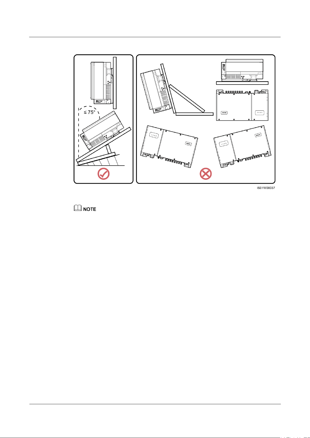
Tilt requirements for installing a SUN2000 on a tilted support:
Install the SUN2000 vertically or at a maximum back tilt of 75 degrees to facilitate heat
dissipation.
Do not install the SUN2000 at a front tilt, excessive back tilt, side tilt, horizontally, or
upside down.
Page 30
SUN2000-(33KTL, 36KTL, 40KTL)-US
User Manual
4 System Installation
Issue 01 (2017-04-01)
Huawei Proprietary and Confidential
Copyright © Huawei Technologies Co., Ltd.
24
Figure 4-3 Tilted support-mounted installation
The SUN2000 may operate with power derating if installed with a tilt.
Installation Space Requirements
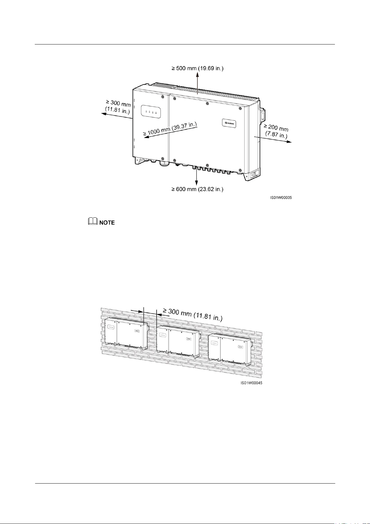
The SUN2000 dimensions (W x H x D, including the mounting plate) are 930 mm x 550
mm x 283 mm (36.61 in. x 21.65 in. x 11.14 in.). Reserve enough clearance around the
SUN2000 to ensure sufficient space for installation and heat dissipation, as shown in
Figure 4-4.
Page 31
SUN2000-(33KTL, 36KTL, 40KTL)-US
User Manual
4 System Installation
Issue 01 (2017-04-01)
Huawei Proprietary and Confidential
Copyright © Huawei Technologies Co., Ltd.
25
Figure 4-4 Installation space requirements
For ease of installing the SUN2000 on the mounting bracket, connecting cables to the bottom of the
SUN2000, and maintaining the SUN2000 in future, it is recommended that the bottom clearance be
between 600 mm (23.62 in.) and 730 mm (28.74 in.). If you have any questions about the distance,
consult the local technical support engineers.
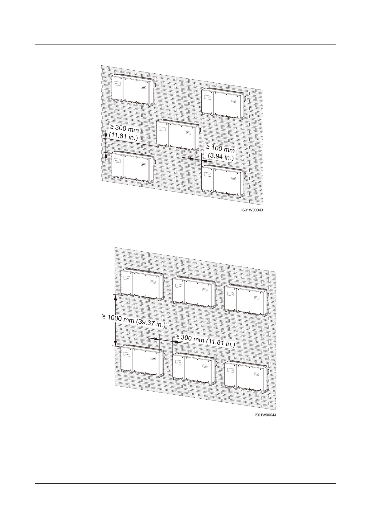
When installing multiple SUN2000s, install them in horizontal mode if sufficient space
is available and install them in triangle mode if no sufficient space is available. Stacked
installation is not recommended. The following figures show the wall-mounted
installation modes and provide reference for other installation modes.
Figure 4-5 Horizontal installation mode (recommended)
Page 32
SUN2000-(33KTL, 36KTL, 40KTL)-US
User Manual
4 System Installation
Issue 01 (2017-04-01)
Huawei Proprietary and Confidential
Copyright © Huawei Technologies Co., Ltd.
26
Figure 4-6 Triangle installation mode (recommended)
Figure 4-7 Stacked installation mode (not recommended)
Page 33
SUN2000-(33KTL, 36KTL, 40KTL)-US
User Manual
4 System Installation
Issue 01 (2017-04-01)
Huawei Proprietary and Confidential
Copyright © Huawei Technologies Co., Ltd.
27
4.4 Moving the Inverter
Context
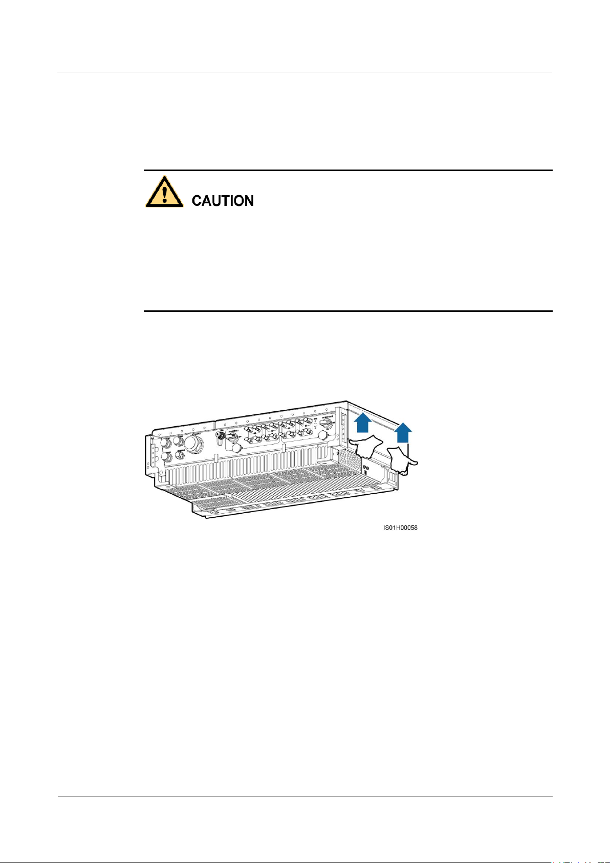
To prevent device damage and personal injury, keep balance when moving the SUN2000
because the SUN2000 is heavy.
Do not place the SUN2000 with its wiring terminals at the bottom contacting the floor or
any other object because the terminals are not designed to support the weight of the
SUN2000.
When placing the SUN2000 on the floor, put foam or paper under the SUN2000 to protect
its cover.
Procedure
Step 1 Arrange two persons to hold the handles on both sides of the SUN2000.
Figure 4-8 Moving the SUN2000
Step 2 Lift the SUN2000 from the packing case and move it to the installation position.
----End
4.5 Installing the Mounting Plate
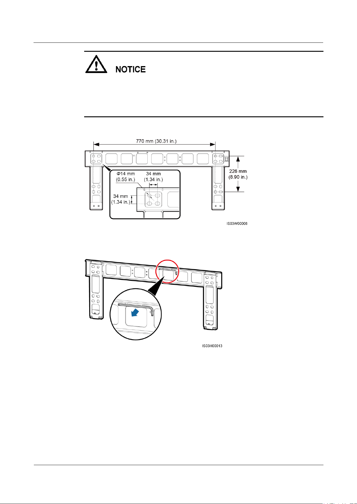
Figure 4-9 shows the SUN2000 mounting plate dimensions. Figure 4-10 shows the position
for saving the security torx wrench.
Page 34
SUN2000-(33KTL, 36KTL, 40KTL)-US
User Manual
4 System Installation
Issue 01 (2017-04-01)
Huawei Proprietary and Confidential
Copyright © Huawei Technologies Co., Ltd.
28
The mounting plate has four groups of tapped holes, each group containing four tapped
holes. Mark any hole in each group based on site requirements and mark four holes in total.
Two round holes are preferred.
Before installing the mounting plate, remove the security torx wrench from the mounting
plate and set it aside.
Figure 4-9 Mounting plate dimensions
Figure 4-10 Position for saving a security torx wrench
4.5.1 Wall-mounted Installation
Procedure
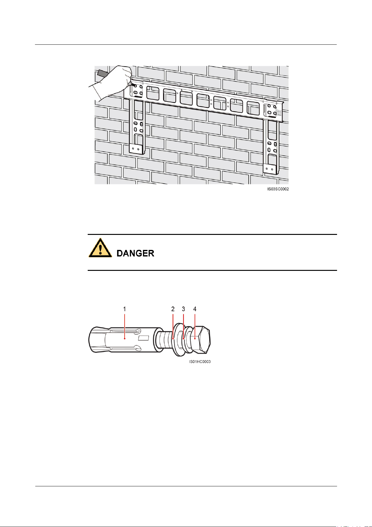
Step 1 Determine the positions for drilling holes using the mounting bracket. Level the hole positions
using a level, and mark the hole positions using a marker.
Page 35
SUN2000-(33KTL, 36KTL, 40KTL)-US
User Manual
4 System Installation
Issue 01 (2017-04-01)
Huawei Proprietary and Confidential
Copyright © Huawei Technologies Co., Ltd.
29
Figure 4-11 Determining hole positions
(1) Expansion sleeve
(2) Flat washer
(3) Spring washer
(4) Bolt
Step 2 Drill holes using a hammer drill and install the delivered expansion bolts.
Avoid drilling holes in the water pipes and power cables buried in the wall.
An expansion bolt contains four parts, as shown in Figure 4-12.
Figure 4-12 Expansion bolt components
Page 36
SUN2000-(33KTL, 36KTL, 40KTL)-US
User Manual
4 System Installation
Issue 01 (2017-04-01)
Huawei Proprietary and Confidential
Copyright © Huawei Technologies Co., Ltd.
30
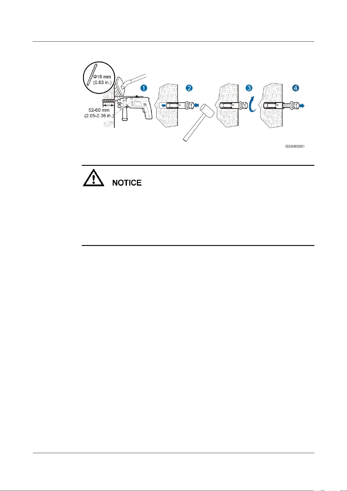
Figure 4-13 Drilling a hole and installing an expansion bolt
To prevent dust inhalation or contact with eyes, wear safety goggles and an anti-dust
respirator when drilling holes.
Wipe away any dust in or around the holes and measure the hole distance. If the holes are
inaccurately positioned, drill holes again.
Level the head of the expansion sleeve with the concrete wall after removing the bolt,
spring washer, and flat washer. Otherwise, the mounting bracket will not be securely
installed on the concrete wall.
1. Drill a hole at a marked hole position in the wall using a hammer drill.
2. Slightly tighten an expansion bolt, vertically insert an expansion bolt into a hole, and
knock the expansion bolt completely into the hole by using a rubber mallet.
3. Partially tighten the expansion bolt.
4. Remove the nut, spring washer, and flat washer.
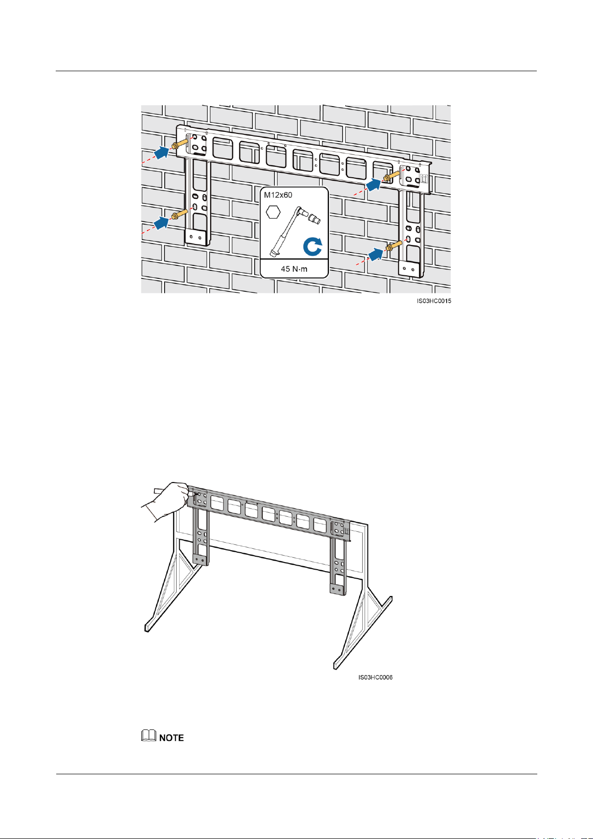
Step 3 Align the mounting bracket holes with the drilled holes, insert expansion bolts into the holes
through the mounting bracket, and then tighten the expansion bolts.
Page 37
SUN2000-(33KTL, 36KTL, 40KTL)-US
User Manual
4 System Installation
Issue 01 (2017-04-01)
Huawei Proprietary and Confidential
Copyright © Huawei Technologies Co., Ltd.
31
Figure 4-14 Securing a mounting bracket
----End
4.5.2 Common Support-mounted Installation
Procedure
Step 1 Determine the positions for drilling holes using the mounting bracket. Level the hole positions
using a level, and mark the hole positions using a marker.
Figure 4-15 Determining hole positions
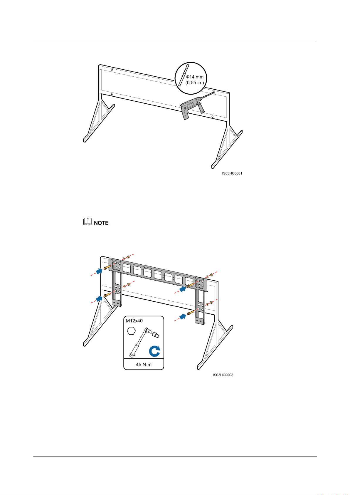
Step 2 Drill holes using a hammer drill.
You are advised to apply anti-rust paint on the hole positions for protection.
Page 38
SUN2000-(33KTL, 36KTL, 40KTL)-US
User Manual
4 System Installation
Issue 01 (2017-04-01)
Huawei Proprietary and Confidential
Copyright © Huawei Technologies Co., Ltd.
32
Figure 4-16 Drilling holes
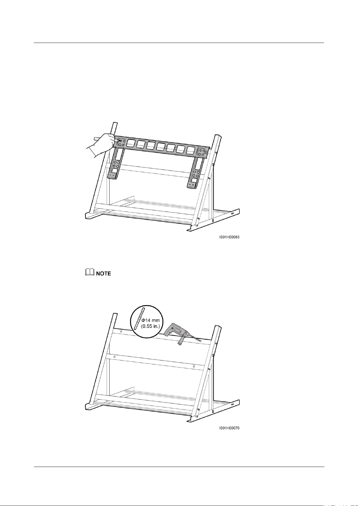
Step 3 Align the mounting bracket holes with the drilled holes, insert the delivered bolt assemblies
(flat washers, spring washers, and bolts) into the holes through the mounting bracket, and
secure them using the stainless steel nuts and flat washers.
If the screw length does not meet the installation requirements, prepare M12 bolt assemblies by yourself.
Figure 4-17 Securing a mounting bracket
----End
Page 39
SUN2000-(33KTL, 36KTL, 40KTL)-US
User Manual
4 System Installation
Issue 01 (2017-04-01)
Huawei Proprietary and Confidential
Copyright © Huawei Technologies Co., Ltd.
33
4.5.3 Tilted Support-mounted Installation
Procedure
Step 1 Determine the positions for drilling holes using the mounting bracket. Level the hole positions
using a level, and mark the hole positions using a marker.
Figure 4-18 Determining hole positions
Step 2 Drill holes using a hammer drill.
You are advised to apply anti-rust paint on the hole positions for protection.
Figure 4-19 Drilling holes
Page 40
SUN2000-(33KTL, 36KTL, 40KTL)-US
User Manual
4 System Installation
Issue 01 (2017-04-01)
Huawei Proprietary and Confidential
Copyright © Huawei Technologies Co., Ltd.
34
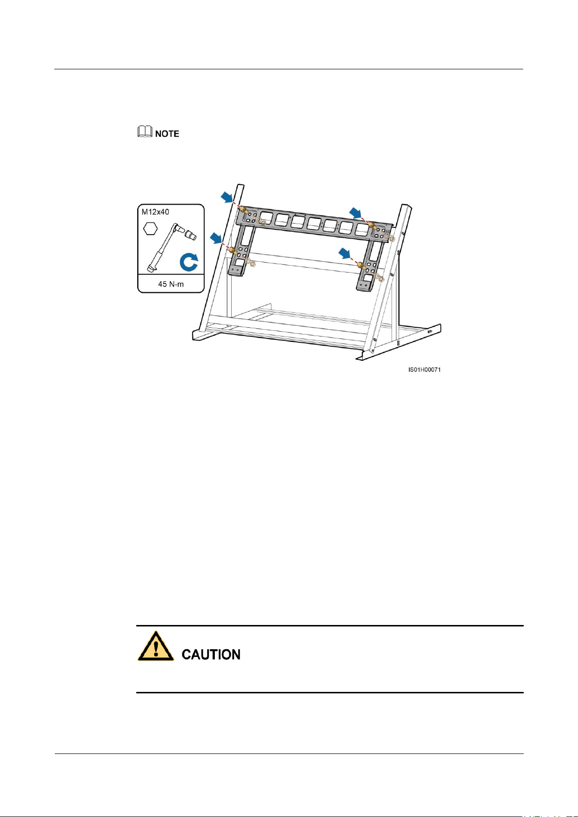
Step 3 Align the mounting bracket holes with the drilled holes, insert the delivered bolt assemblies
(flat washers, spring washers, and bolts) into the holes through the mounting bracket, and
secure them using the stainless steel nuts and flat washers.
If the screw length does not meet the installation requirements, prepare M12 bolt assemblies by yourself.
Figure 4-20 Securing a mounting bracket
----End
4.6 Installing the SUN2000
Procedure
Step 1 If the installation position is low and you can mount the SUN2000 onto the mounting bracket,
go to Step 3 and then Step 5.
Step 2 If the installation position is high and you cannot mount the SUN2000 onto the mounting
bracket, perform Step 3 to Step 6.
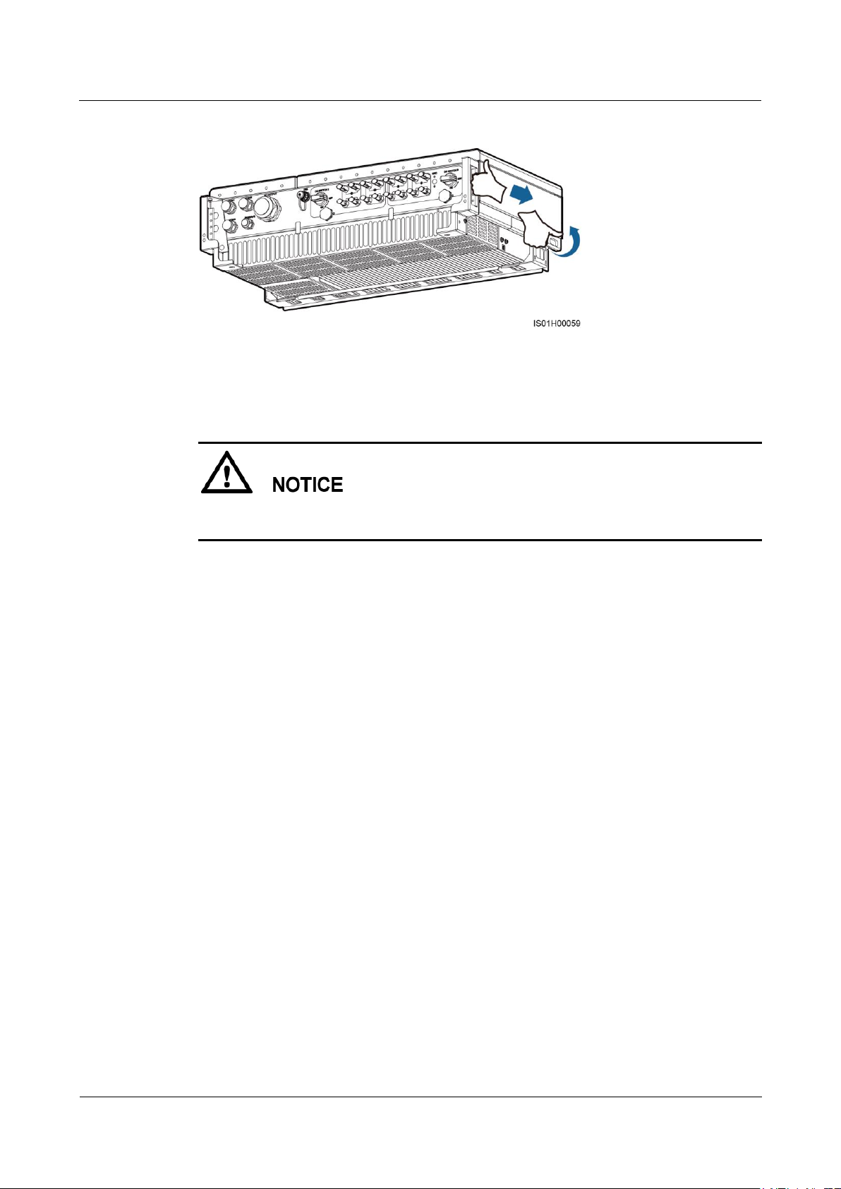
Step 3 Ensure that two people lift the SUN2000 and turn it upright. Lift the SUN2000 by grasping
the handle at the bottom of the SUN2000 with one hand and the handle at the top with the
other.
To prevent personal injury caused by a falling SUN2000, keep balance when lifting the
SUN2000 because it is heavy.
Page 41
SUN2000-(33KTL, 36KTL, 40KTL)-US
User Manual
4 System Installation
Issue 01 (2017-04-01)
Huawei Proprietary and Confidential
Copyright © Huawei Technologies Co., Ltd.
35
Figure 4-21 Lifting a SUN2000
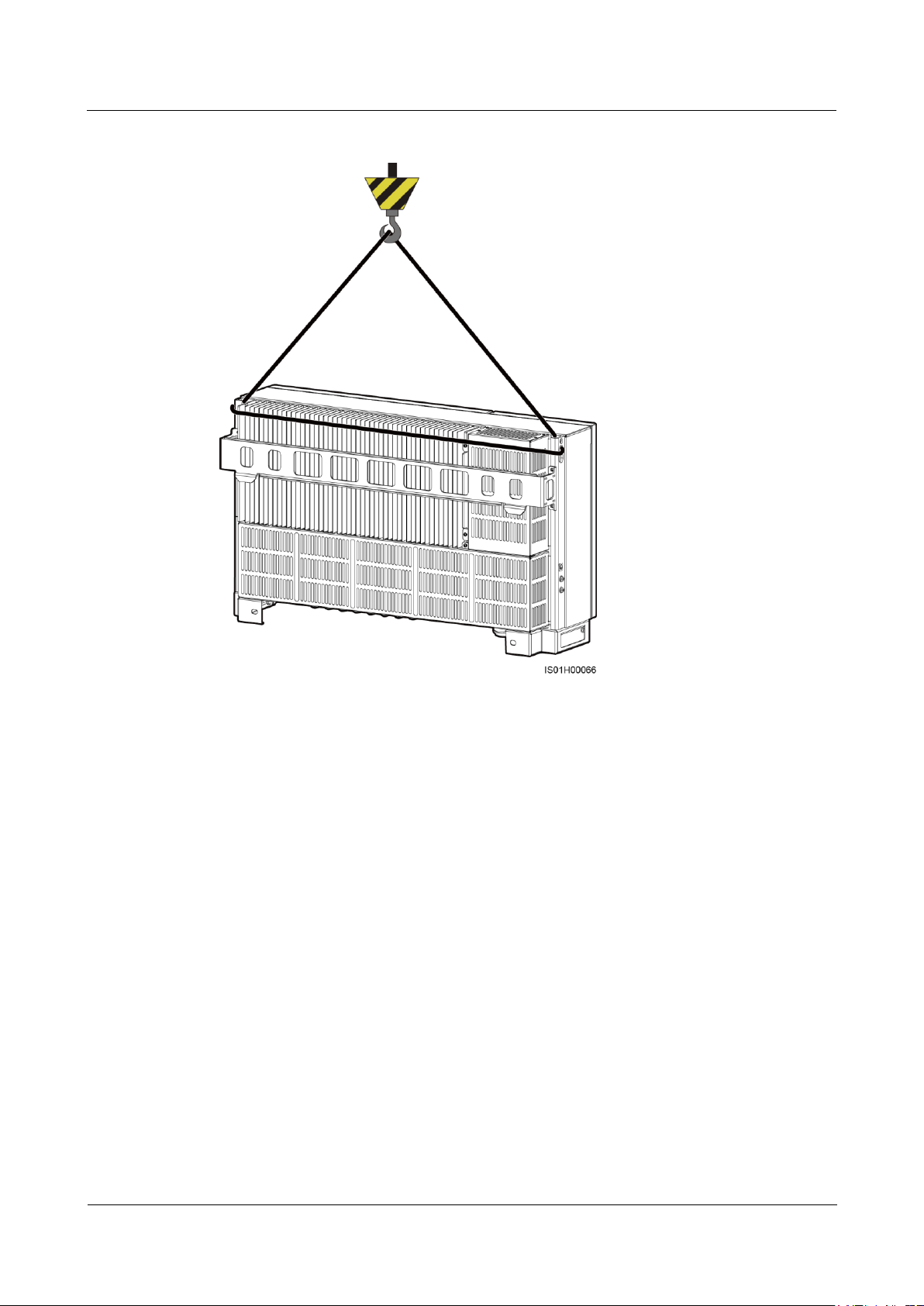
Step 4 Run a rope that is strong enough to bear the SUN2000 through the lifting eyes and hoist the
SUN2000.
When hoisting the SUN2000, keep balance to protect the SUN2000 from colliding with the
wall or other objects.
Page 42
SUN2000-(33KTL, 36KTL, 40KTL)-US
User Manual
4 System Installation
Issue 01 (2017-04-01)
Huawei Proprietary and Confidential
Copyright © Huawei Technologies Co., Ltd.
36
Figure 4-22 Hoisting a SUN2000
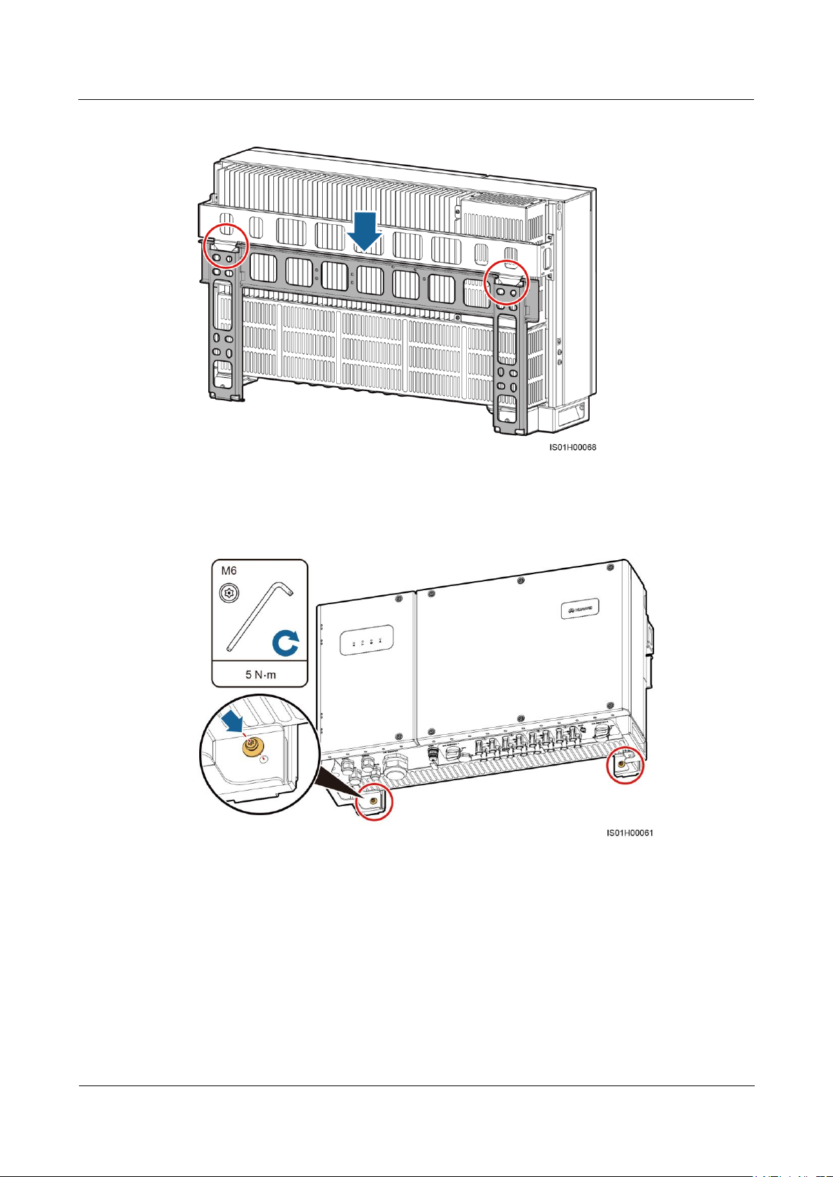
Step 5 Install the SUN2000 on the mounting bracket and level the SUN2000 chassis with the
mounting bracket.
Page 43
SUN2000-(33KTL, 36KTL, 40KTL)-US
User Manual
4 System Installation
Issue 01 (2017-04-01)
Huawei Proprietary and Confidential
Copyright © Huawei Technologies Co., Ltd.
37
Figure 4-23 Mounting the SUN2000 onto the mounting bracket
Step 6 Tighten the two security torx screws using a security torx wrench to a torque of 5 N·m.
Figure 4-24 Tightening security torx screws
----End
Page 44
SUN2000-(33KTL, 36KTL, 40KTL)-US
User Manual
5 Connecting Cables
Issue 01 (2017-04-01)
Huawei Proprietary and Confidential
Copyright © Huawei Technologies Co., Ltd.
38
Precautions
5 Connecting Cables
Before connecting cables, ensure that the two DC switches on the inverter are OFF. Otherwise,
the high voltage of the inverter may result in electric shocks.
The cable colors shown in the electrical connection drawings provided in this chapter are for reference
only. Select cables in accordance with local cable specifications (green-and-yellow wires are used for
grounding only).
5.1 Preparing OT Terminals
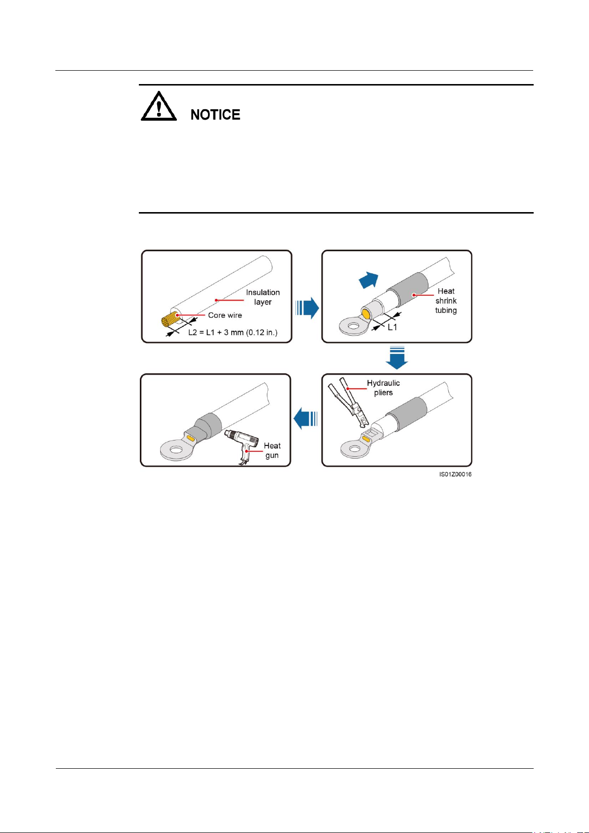
Figure 5-1 shows how to prepare an OT terminal.
Page 45
SUN2000-(33KTL, 36KTL, 40KTL)-US
User Manual
5 Connecting Cables
Issue 01 (2017-04-01)
Huawei Proprietary and Confidential
Copyright © Huawei Technologies Co., Ltd.
39
Avoid scratching the core wire when stripping a cable.
The cavity formed after the conductor crimp strip of the OT terminal is crimped must wrap
the core wires completely. The core wires must contact the OT terminal closely.
Wrap the wire crimping area with heat shrink tubing or PVC insulation tape. The
following figure uses heat shrink tubing as an example.
When using the heat gun, protect devices from being scorched.
Figure 5-1 Preparing an OT terminal
5.2 Connecting the Ground Cable
Page 46

SUN2000-(33KTL, 36KTL, 40KTL)-US
User Manual
5 Connecting Cables
Issue 01 (2017-04-01)
Huawei Proprietary and Confidential
Copyright © Huawei Technologies Co., Ltd.
40
Proper grounding is helpful for resisting the impact of surge voltage and improving the
electromagnetic interference (EMI) performance. Before connecting the AC power cable,
DC power cable, and communications cable, connect ground cables to the PE point and
PV side ground point.
It is recommended that the ground cable be connected to a nearby ground point. Connect
the ground points of all SUN2000s in the same PV array to ensure equipotential
connections to ground cables.
5.2.1 Grounding the SUN2000 over a PE Point
Prerequisites
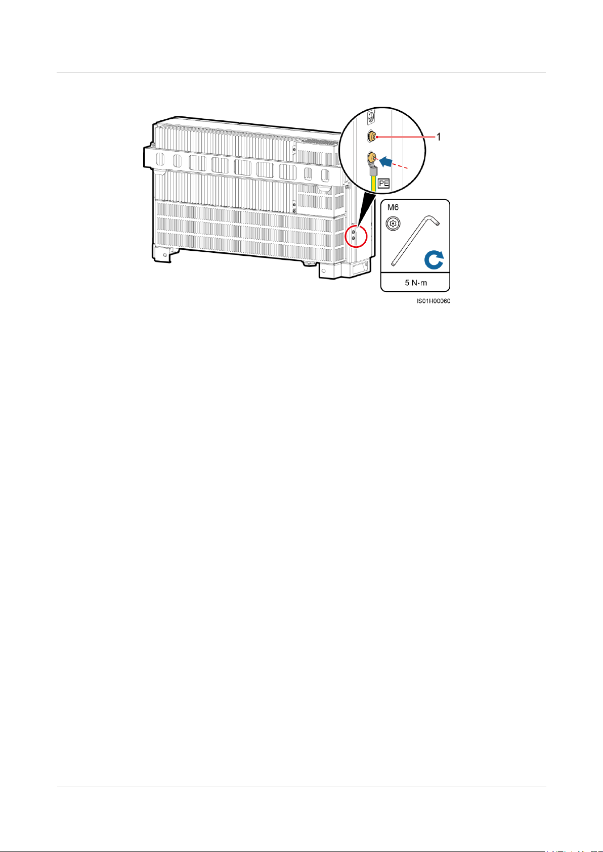
Both the shell and maintenance compartment of the SUN2000 provide a PE point. Select
either for connecting the ground cable.
If you connect a ground cable to the PE point on the shell, ensure that the ground cable
and OT terminal are available.
− Recommended ground cable: an outdoor copper-core cable with a cross-sectional
area of 6 AWG or more
− OT terminal: M6
If you connect a ground cable to the PE point in the maintenance compartment, prepare
the AC output power cable together with the ground cable. For details, see 5.4
Connecting AC Output Power Cables.
Context
Procedure
Step 1 Prepare the OT terminal.
Step 2 Secure the ground cable using the ground screw.
There are two PE points on the chassis shell and one of them is standby.
Page 47
SUN2000-(33KTL, 36KTL, 40KTL)-US
User Manual
5 Connecting Cables
Issue 01 (2017-04-01)
Huawei Proprietary and Confidential
Copyright © Huawei Technologies Co., Ltd.
41
Figure 5-2 Connecting a ground cable
(1) Reserved PE point
----End
Follow-up Procedure
To enhance the corrosion resistance of the ground terminal, apply silica gel or paint on the
ground terminal after connecting the ground cable.
5.2.2 PV Side Grounding
Prerequisites
A ground cable and an OT terminal are available.
Recommended ground cable: an outdoor copper-core cable with a cross-sectional area of
6 AWG or more
OT terminal: M6
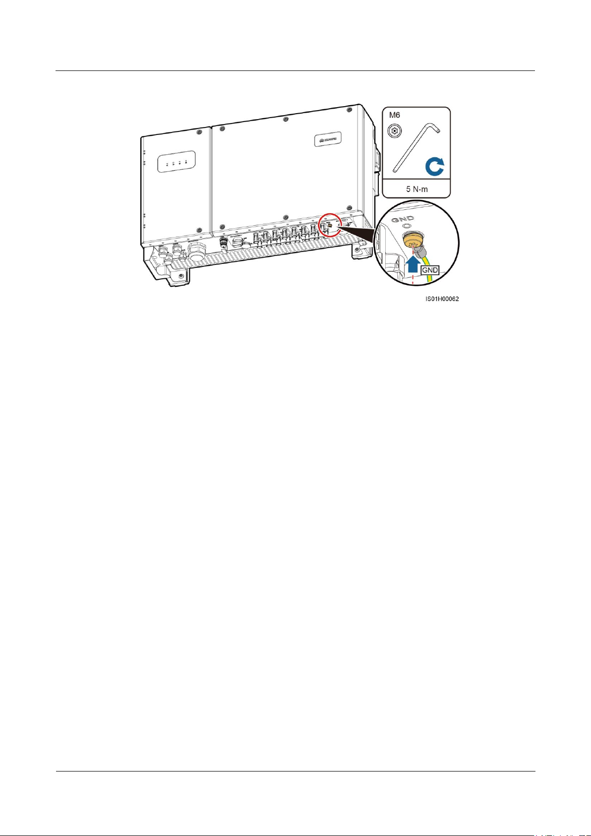
Procedure
Step 1 Prepare the OT terminal.
Step 2 Secure the ground cable using the ground screw.
Page 48
SUN2000-(33KTL, 36KTL, 40KTL)-US
User Manual
5 Connecting Cables
Issue 01 (2017-04-01)
Huawei Proprietary and Confidential
Copyright © Huawei Technologies Co., Ltd.
42
Figure 5-3 Connecting a ground cable
----End
Follow-up Procedure
To enhance the corrosion resistance of the ground terminal, apply silica gel or paint on the
ground terminal after connecting the ground cable.
5.3 Opening the Maintenance Compartment Door
Prerequisites
Page 49
SUN2000-(33KTL, 36KTL, 40KTL)-US
User Manual
5 Connecting Cables
Issue 01 (2017-04-01)
Huawei Proprietary and Confidential
Copyright © Huawei Technologies Co., Ltd.
43
Procedure
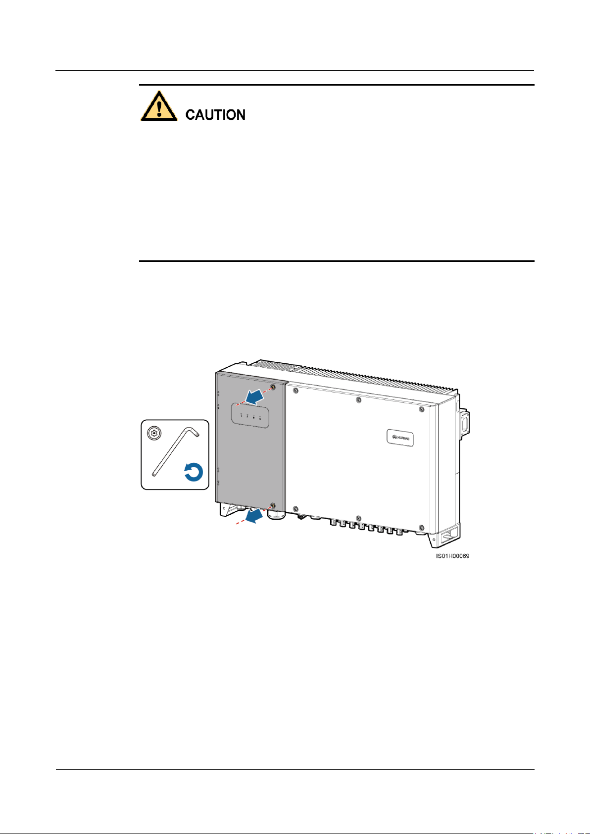
Step 1 Remove the two screws from the maintenance compartment door using a security torx wrench
Never open the host panel of the SUN2000.
Before opening the maintenance compartment door, disconnect the AC and DC power
supplies. For processes of disconnecting the power supplies, see 6.3 Powering Off the
SUN2000. After powering off the SUN2000, wait at least 5 minutes before performing
operations on it.
If you need to open the maintenance compartment door in rainy or snowy days, take
protective measures to prevent rain and snow entering the maintenance compartment. If it
is impossible to take protective measures, do not open the maintenance compartment door
in rainy or snowy days.
Do not leave unused screws in the maintenance compartment.
and set them aside.
Figure 5-4 Removing screws
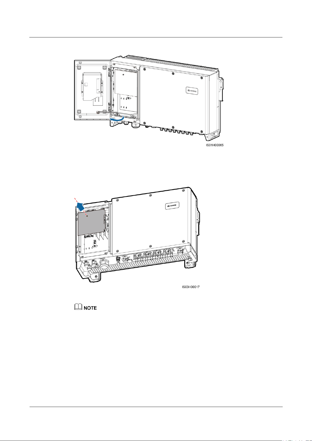
Step 2 Open the maintenance compartment door and adjust the support bar.
Page 50
SUN2000-(33KTL, 36KTL, 40KTL)-US
User Manual
5 Connecting Cables
Issue 01 (2017-04-01)
Huawei Proprietary and Confidential
Copyright © Huawei Technologies Co., Ltd.
44
Figure 5-5 Adjusting a support bar
Step 3 Remove the AC terminal cover and set it aside.
Figure 5-6 Removing an AC terminal cover
To highlight the involved area, the figure does not show the open door.
----End
5.4 Connecting AC Output Power Cables
An AC switch must be installed on the AC side of the SUN2000 to ensure that the SUN2000
can be safely disconnected from the power grid. See 10 Technical Specifications to select AC
switches of the appropriate specifications.
Page 51
SUN2000-(33KTL, 36KTL, 40KTL)-US
User Manual
5 Connecting Cables
Issue 01 (2017-04-01)
Huawei Proprietary and Confidential
Copyright © Huawei Technologies Co., Ltd.
45
Cable Specifications
Copper-Core Cable
Copper-Clad
Aluminum Cable or
Aluminum Alloy
Cable
Conductor
cross-sectional area
Value
range
6–2/0 AWG
4–2/0 AWG
Recomm
ended
value
4 AWG
2 AWG
Cable outer diameter
6.3–12.1 mm (0.25–0.48 in.)
Do not connect loads between the SUN2000 and the AC switch.
Connect AC output power cables according to the requirements specified by local power
grid operators.
The AC output power cable can be connected in a common way or through a pipe.
5.4.1 Connection Through a Pipe
Prerequisites
The AC output power cable, OT terminal, and pipe are available.
Use cables that can withstand 90°C (194°F) or 105°C (221°F). The cable that can
withstand 105°C (221°F) is recommended. To facilitate installation, use flexible cables.
If you connect a ground cable to the PE point on the chassis shell in the scenario with no
neutral wire, you are advised to use three (L1, L2, and L3) single-core outdoor cables.
If you connect a ground cable to the PE point in the maintenance compartment in the
scenario with no neutral wire, you are advised to use four (L1, L2, L3, and PE)
single-core outdoor cables.
If you connect a ground cable to the PE point on the chassis shell in the scenario with a
neutral wire, you are advised to use four (L1, L2, L3, and N) single-core outdoor cables.
If you connect a ground cable to the PE point in the maintenance compartment in the
scenario with a neutral wire, you are advised to use five (L1, L2, L3, N, and PE)
single-core outdoor cables.
Table 5-1 describes the cable specifications.
Table 5-1 Cable specifications
OT terminal: M8 (L1, L2, L3, and N) and M6 (PE)
Pipe: 2-inch pipe
Page 52
SUN2000-(33KTL, 36KTL, 40KTL)-US
User Manual
5 Connecting Cables
Issue 01 (2017-04-01)
Huawei Proprietary and Confidential
Copyright © Huawei Technologies Co., Ltd.
46
Context
(1) Nut
(2) Fitting
(3) Conduit
The pipe specifications should comply with the waterproof connector specifications. For
example, for a 2-inch waterproof connector, prepare a 2-inch pipe.
Figure 5-7 Pipe
The pipe appearance is for reference only. The actual pipe prevails.
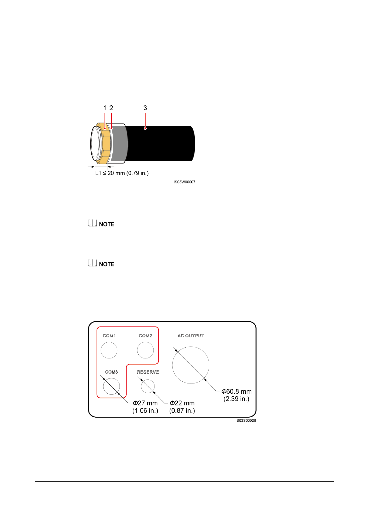
Figure 5-8 shows the diameters of the cable holes at the bottom of the chassis after the
waterproof connectors are removed.
Following are the reference torque values for the waterproof connector and pipe. Observe the
requirements of the specific manufacturer, if any.
AC OUTPUT and COM ports: 7.5 N·m (plastic) or 10 N·m (metal)
RESERVE port: 3.75 N·m (plastic) or 6.25 N·m (metal)
Figure 5-8 Diameters of the bottom cable holes
Procedure
Step 1 Install the pipe fitting.
Page 53
SUN2000-(33KTL, 36KTL, 40KTL)-US
User Manual
5 Connecting Cables
Issue 01 (2017-04-01)
Huawei Proprietary and Confidential
Copyright © Huawei Technologies Co., Ltd.
47
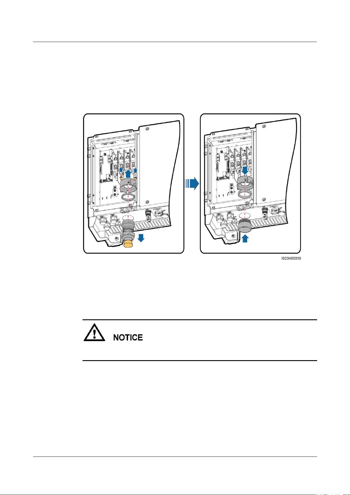
1. Remove the AC filter and keep the screws aside.
2. Remove the locking cap and plug from the waterproof connector, and then remove the
waterproof connector.
3. Secure the pipe fitting to the chassis using the nut delivered with the pipe.
4. Place the AC filter.
Figure 5-9 Installing pipe fitting
Step 2 Route the AC output power cable through the conduit and fitting of the pipe, and then the AC
filter.
Step 3 Prepare the OT terminal.
Pay attention to the OT terminal and ensure that it can successfully connect to the AC
terminal block.
Page 54
SUN2000-(33KTL, 36KTL, 40KTL)-US
User Manual
5 Connecting Cables
Issue 01 (2017-04-01)
Huawei Proprietary and Confidential
Copyright © Huawei Technologies Co., Ltd.
48
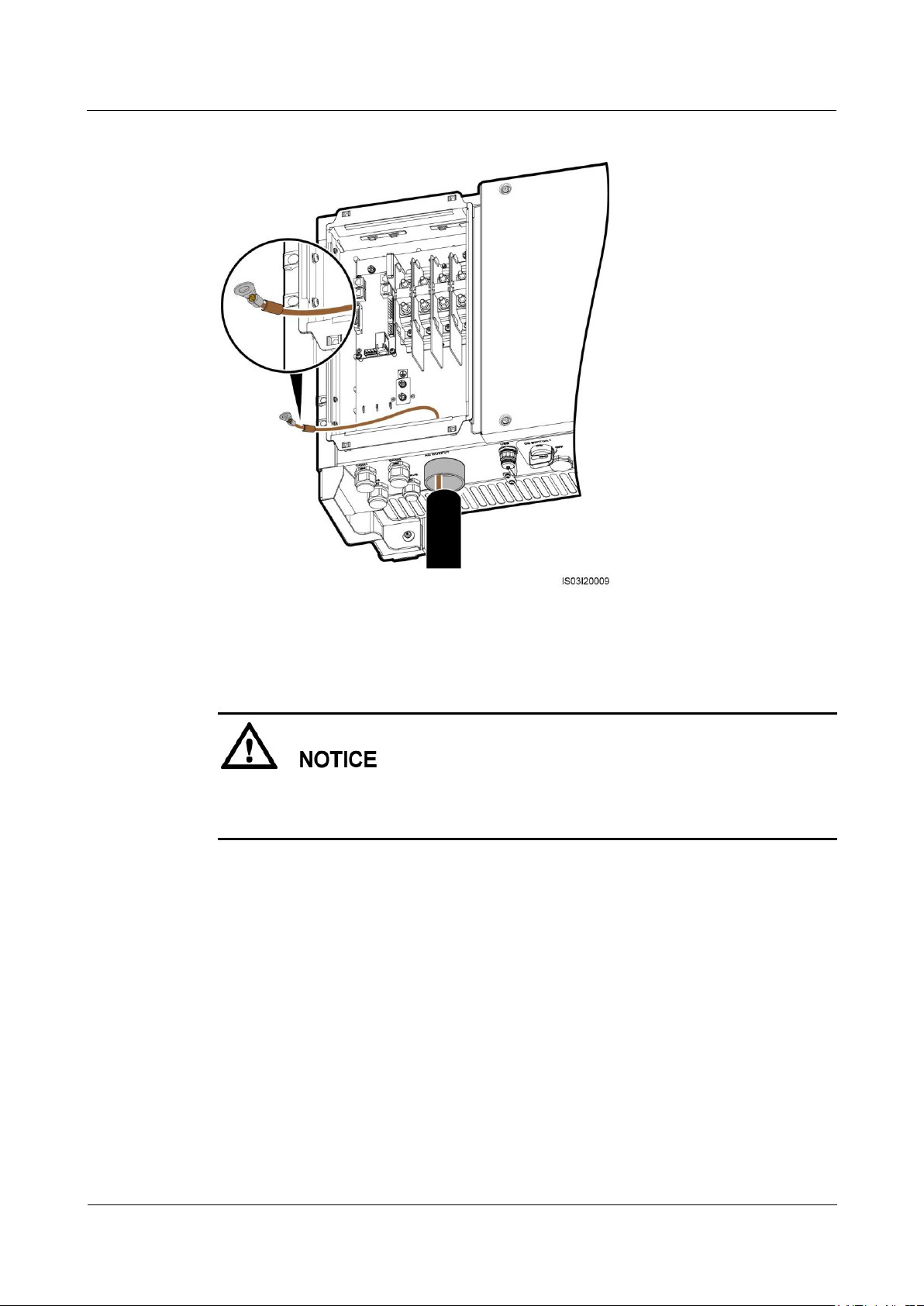
Figure 5-10 OT terminal direction (using one cable as an example)
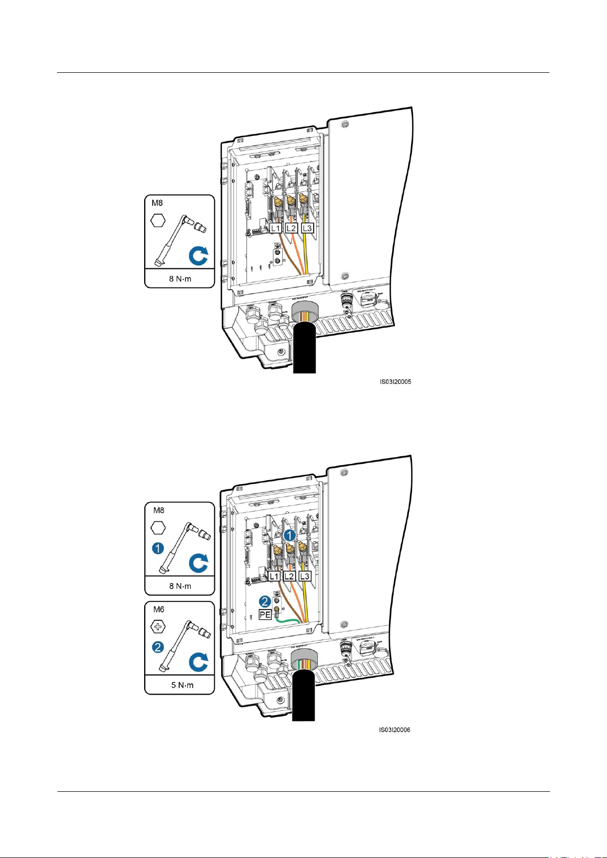
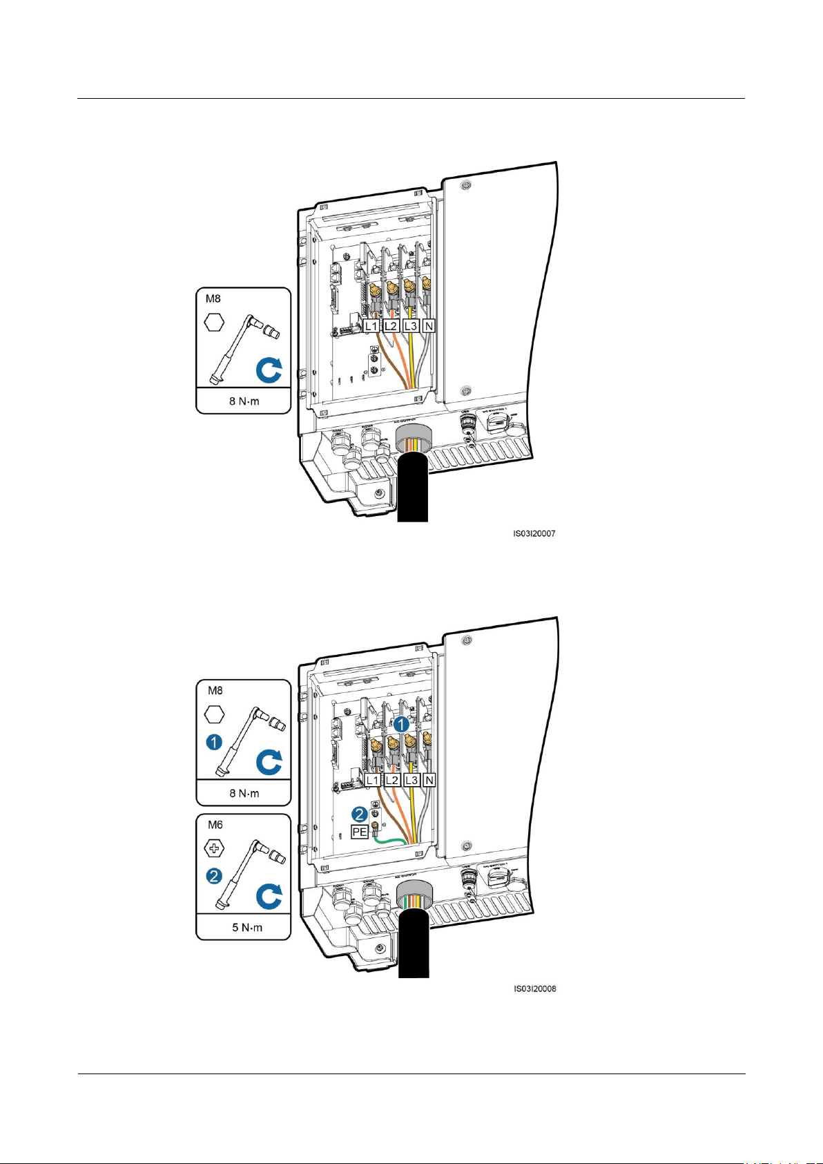
Step 4 Connect the AC output power cable and secure it using a socket wrench with an extension
rod.
Verify that the AC output power cable is connected securely. Otherwise, the SUN2000 may
fail to operate or experience any fault that will cause the damage of the terminal block. For
example, the SUN2000 may generate heat during operating due to unreliable connection.
Page 55
SUN2000-(33KTL, 36KTL, 40KTL)-US
User Manual
5 Connecting Cables
Issue 01 (2017-04-01)
Huawei Proprietary and Confidential
Copyright © Huawei Technologies Co., Ltd.
49
Figure 5-11 Connecting the AC output power cable (excluding the ground cable and neutral wire)
Figure 5-12 Connecting the AC output power cable (including the ground cable but excluding the
neutral wire)
Page 56
SUN2000-(33KTL, 36KTL, 40KTL)-US
User Manual
5 Connecting Cables
Issue 01 (2017-04-01)
Huawei Proprietary and Confidential
Copyright © Huawei Technologies Co., Ltd.
50
Figure 5-13 Connecting the AC output power cable (excluding the ground cable but including the
neutral wire)
Figure 5-14 Connecting the AC output power cable (including the ground cable and neutral wire)
Page 57
SUN2000-(33KTL, 36KTL, 40KTL)-US
User Manual
5 Connecting Cables
Issue 01 (2017-04-01)
Huawei Proprietary and Confidential
Copyright © Huawei Technologies Co., Ltd.
51
Cable Specifications
Copper-Core Cable
Copper-Clad
Aluminum Cable or
Aluminum Alloy
Cable
Conductor
cross-sectional area
Range
6–2/0 AWG
4–2/0 AWG
Recomm
ended
value
4 AWG
2 AWG
Cable outer diameter range
supported by the AC OUTPUT
waterproof connector
37–44 mm (1.46–1.73 in.)
The cable colors in figures are for reference only. Select appropriate cables according to the local
standards.
Step 5 Connect the conduit and fitting of the pipe.
Step 6 Check that the cables are connected correctly and securely. Then take appropriate measures to
ensure that the pipe conduit and fitting are secured reliably, and seal the cable hole using
firestop putty.
Step 7 Secure the AC filter using screws.
Step 8 Clear foreign matter from the maintenance compartment.
----End
5.4.2 Common Connection
Prerequisites
The AC output power cable and OT terminal are available.
Use cables that can withstand 90°C (194°F) or 105°C (221°F). The cable that can
withstand 105°C (221°F) is recommended. To facilitate installation, use flexible cables.
If you connect a ground cable to the PE point on the chassis shell in the scenario without
the neutral wire, you are advised to use a three-core (L1, L2, and L3) outdoor cable.
If you connect a ground cable to the PE point in the maintenance compartment in the
scenario without the neutral wire, you are advised to use a four-core (L1, L2, L3, and PE)
outdoor cable.
If you connect a ground cable to the PE point on the chassis shell in the scenario with the
neutral wire, you are advised to use a four-core (L1, L2, L3, and N) outdoor cable.
If you connect a ground cable to the PE point in the maintenance compartment in the
scenario with the neutral wire, you are advised to use a five-core (L1, L2, L3, N, and PE)
outdoor cable.
Table 5-2 describes the cable specifications.
Table 5-2 Cable specifications
Page 58
SUN2000-(33KTL, 36KTL, 40KTL)-US
User Manual
5 Connecting Cables
Issue 01 (2017-04-01)
Huawei Proprietary and Confidential
Copyright © Huawei Technologies Co., Ltd.
52
Procedure
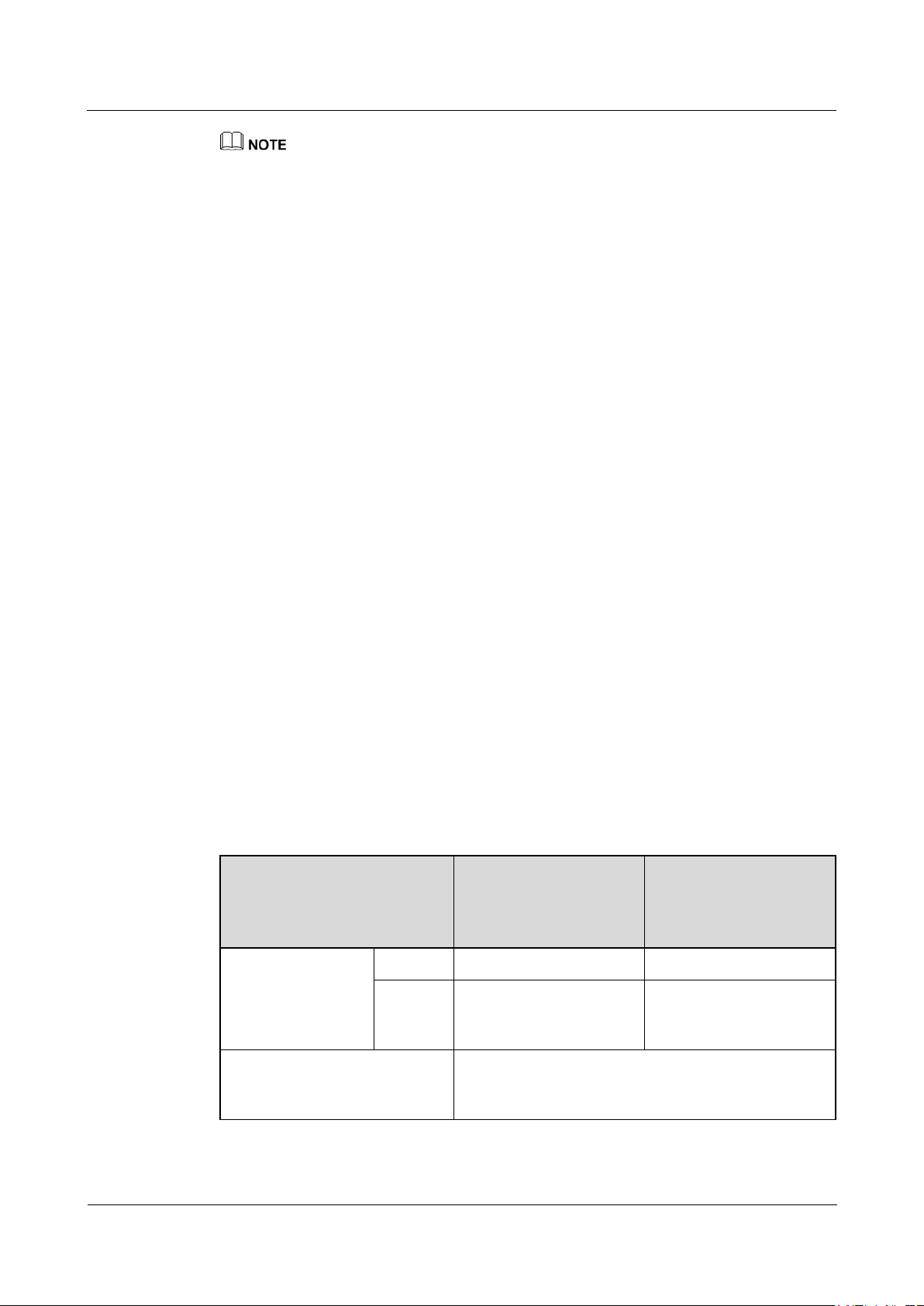
(A) Core wire
(B) Insulation layer
(C) Jacket
Step 1 Remove an appropriate length of the jacket and insulation layer from the AC output power
OT terminal: M8 (L1, L2, L3, and N) and M6 (PE)
cable using a wire stripper.
Ensure that the jacket is in the maintenance compartment.
Figure 5-15 Three-core cable (excluding the ground cable and neutral wire)
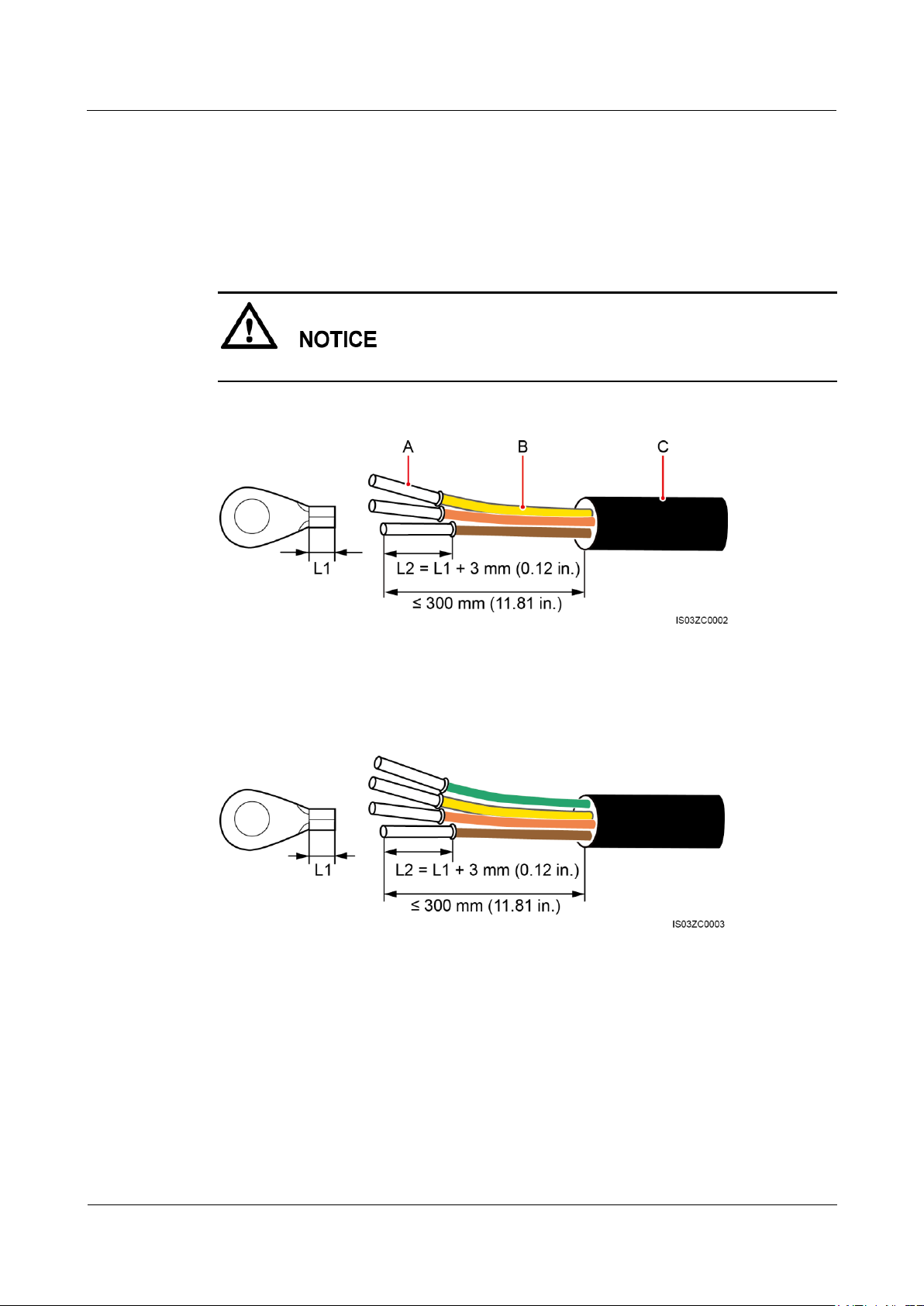
Figure 5-16 Four-core cable (including the ground cable but excluding the neutral wire)
Page 59
SUN2000-(33KTL, 36KTL, 40KTL)-US
User Manual
5 Connecting Cables
Issue 01 (2017-04-01)
Huawei Proprietary and Confidential
Copyright © Huawei Technologies Co., Ltd.
53
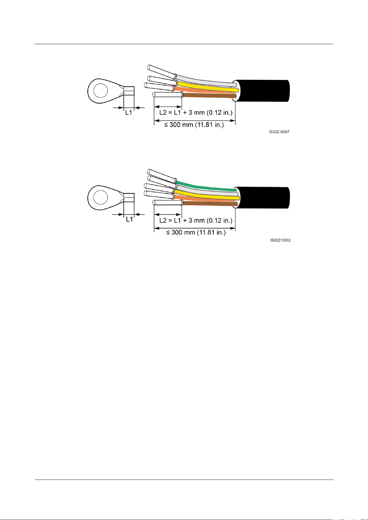
Figure 5-17 Four-core cable (excluding the ground cable but including the neutral wire)
Figure 5-18 Five-core cable (including the ground cable and neutral wire)
Step 2 Prepare the OT terminal.
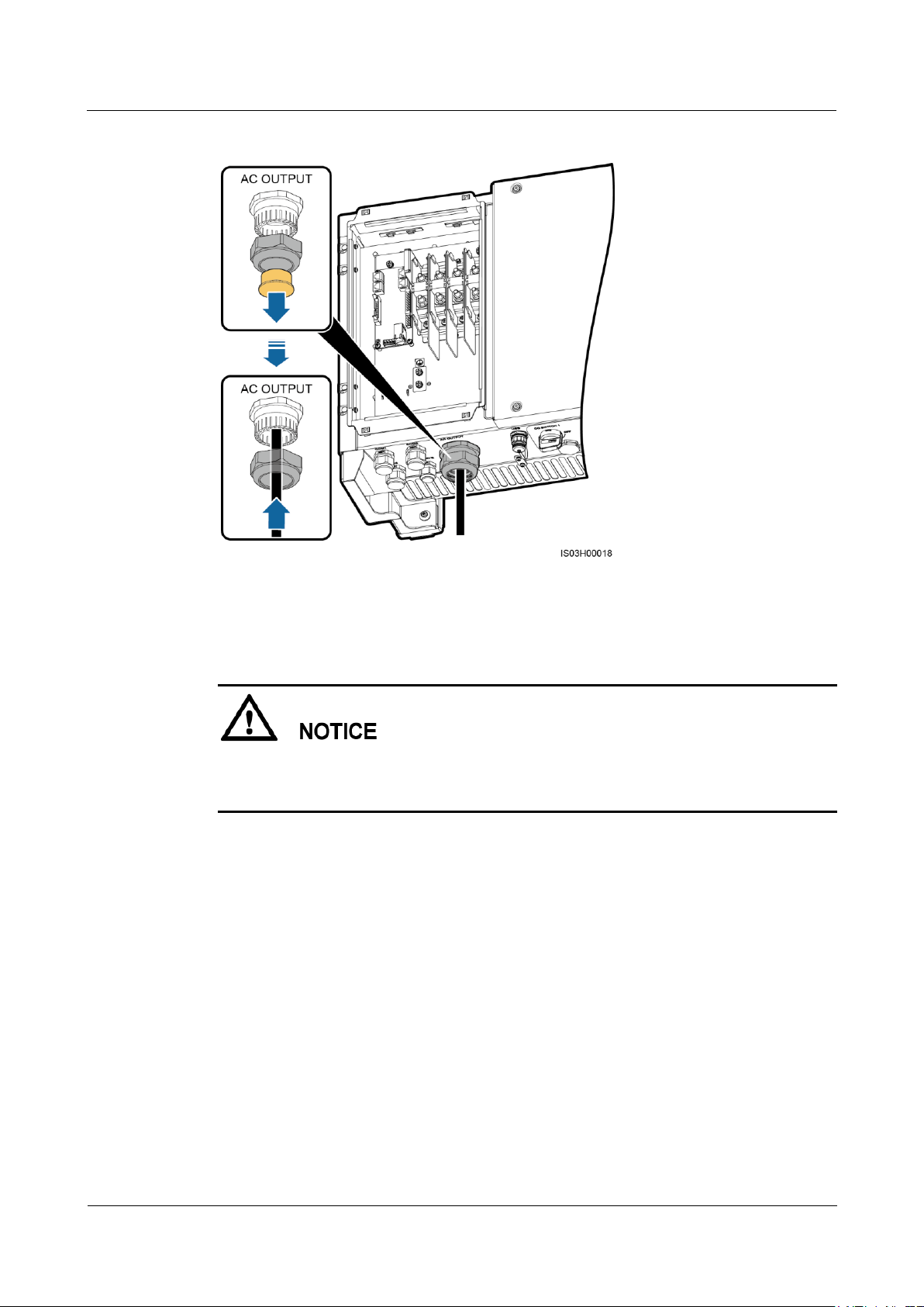
Step 3 Route the cable through the waterproof connector.
Page 60
SUN2000-(33KTL, 36KTL, 40KTL)-US
User Manual
5 Connecting Cables
Issue 01 (2017-04-01)
Huawei Proprietary and Confidential
Copyright © Huawei Technologies Co., Ltd.
54
Figure 5-19 Routing cables
Step 4 Connect the AC output power cable and secure it using a socket wrench with an extension
rod.
Verify that the AC output power cable is connected securely. Otherwise, the SUN2000 may
fail to operate or experience any fault that will cause the damage of the terminal block. For
example, the SUN2000 may generate heat during operating due to unreliable connection.
Page 61
SUN2000-(33KTL, 36KTL, 40KTL)-US
User Manual
5 Connecting Cables
Issue 01 (2017-04-01)
Huawei Proprietary and Confidential
Copyright © Huawei Technologies Co., Ltd.
55
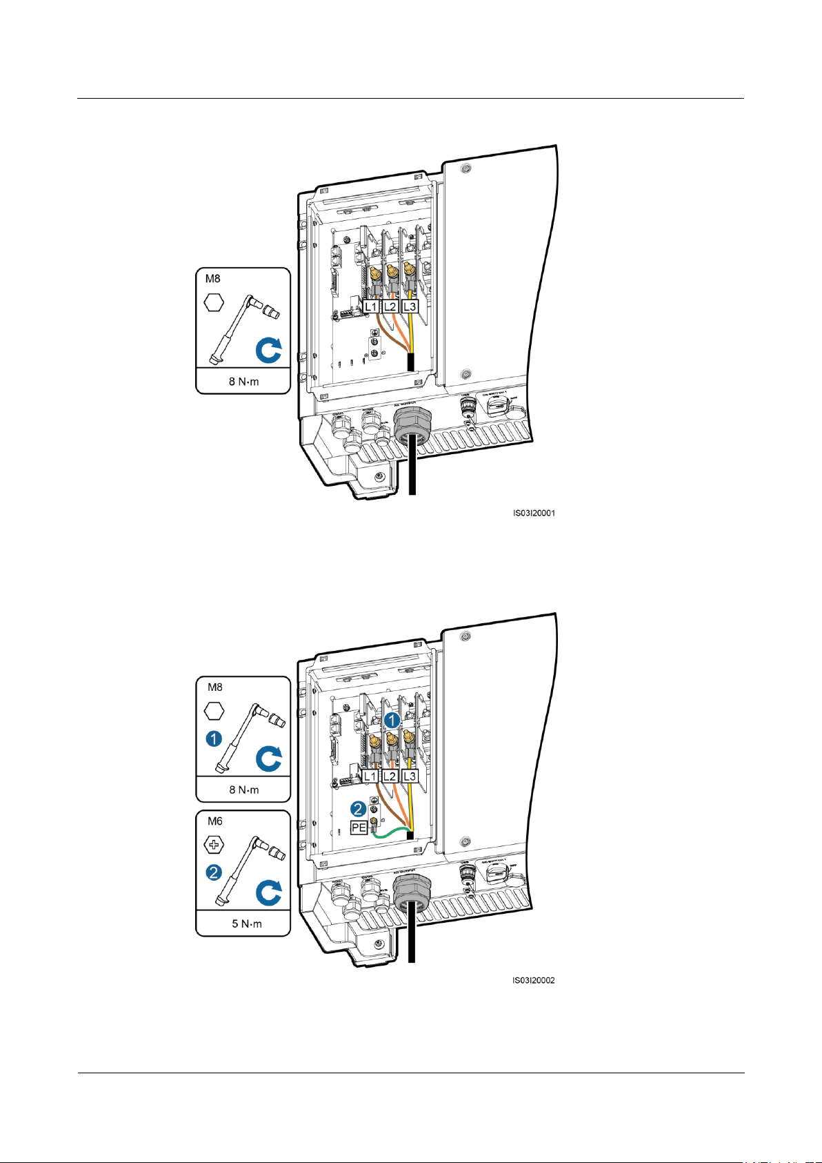
Figure 5-20 Connecting the AC output power cable (excluding the ground cable and neutral wire)
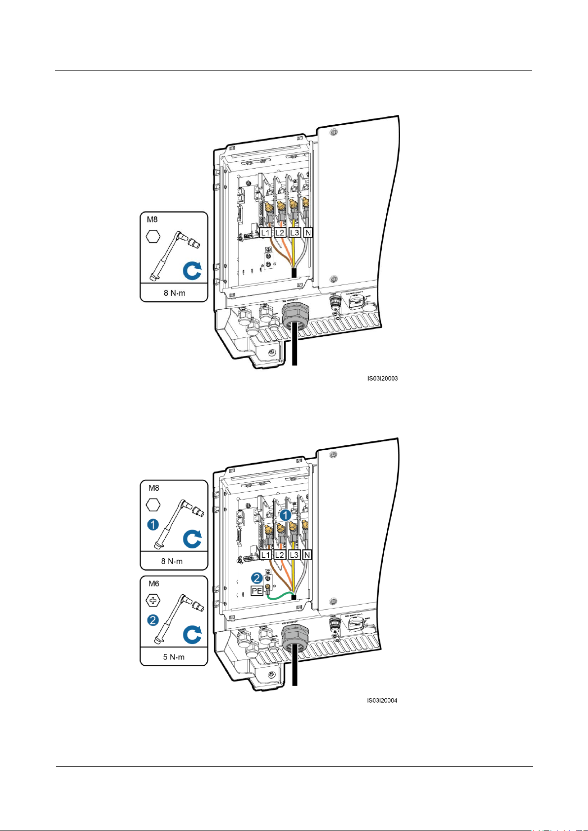
Figure 5-21 Connecting the AC output power cable (including the ground cable but excluding the
neutral wire)
Page 62
SUN2000-(33KTL, 36KTL, 40KTL)-US
User Manual
5 Connecting Cables
Issue 01 (2017-04-01)
Huawei Proprietary and Confidential
Copyright © Huawei Technologies Co., Ltd.
56
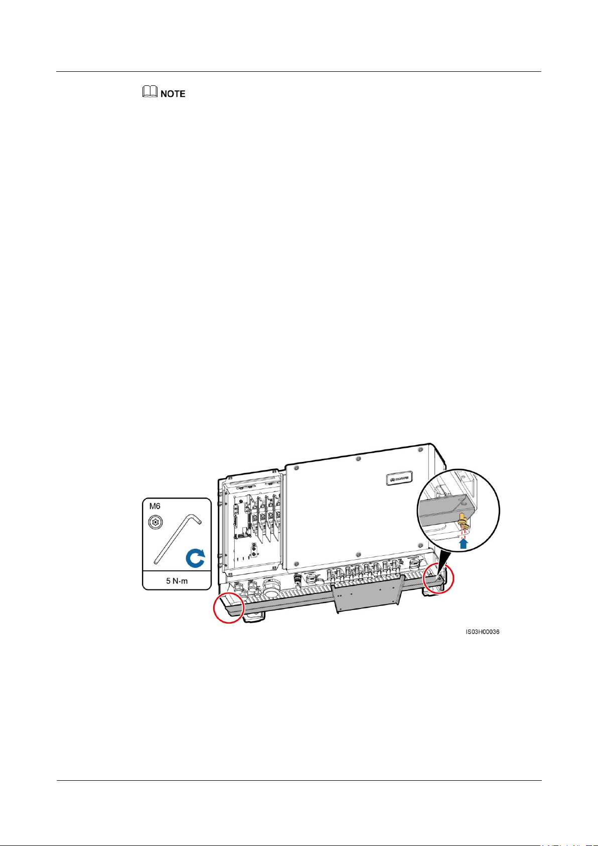
Figure 5-22 Connecting the AC output power cable (excluding the ground cable but including the
neutral wire)
Figure 5-23 Connecting the AC output power cable (including the ground cable and neutral wire)
Page 63
SUN2000-(33KTL, 36KTL, 40KTL)-US
User Manual
5 Connecting Cables
Issue 01 (2017-04-01)
Huawei Proprietary and Confidential
Copyright © Huawei Technologies Co., Ltd.
57
The cable colors in figures are for reference only. Select appropriate cables according to the local
standards.
Step 5 Tighten the waterproof connector to a torque of 7.5 N•m.
----End
Follow-up Procedure
Check that the cables are connected correctly and securely. Then apply firestop putty to the
waterproof connectors and cable holes. Clear foreign matter from the maintenance
compartment.
5.5 (Optional) Installing the DC Protection Shroud
Context
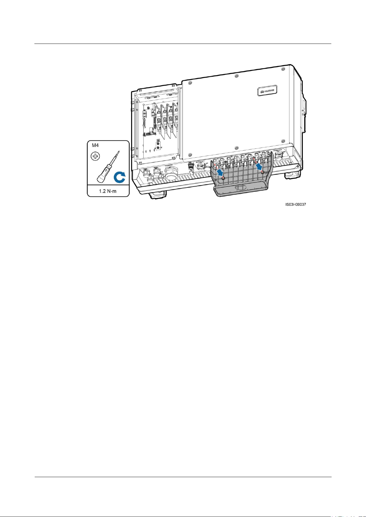
To avoid electric shocks, you are advised to install a DC protection shroud in a rooftop PV
plant.
Procedure
Step 1 Install the protection shroud bracket.
Step 2 Install the protection shroud rear panel.
Figure 5-24 Installing a bracket
Page 64
SUN2000-(33KTL, 36KTL, 40KTL)-US
User Manual
5 Connecting Cables
Issue 01 (2017-04-01)
Huawei Proprietary and Confidential
Copyright © Huawei Technologies Co., Ltd.
58
Figure 5-25 Installing a rear panel
----End
Follow-up Procedure
After finishing the preceding steps and preparing a 2-inch pipe, perform the following steps.
Otherwise, you may need to rework.
1. Secure the pipe fitting to the chassis using the nut delivered with the pipe.
2. Route the DC input power cable through the conduit and then fitting of the pipe.
3. Connect the DC input power cable by following the instructions in 5.6 Connecting DC
Input Power Cables.
4. Connect the conduit and fitting of the pipe.
5. Check that the cables are connected correctly and securely. Then take appropriate
measures to ensure that the pipe conduit and fitting are secured reliably, and seal the
cable hole using firestop putty.
6. Clear foreign matter from the protection shroud.
7. Install the front cover of the protection shroud.
Page 65
SUN2000-(33KTL, 36KTL, 40KTL)-US
User Manual
5 Connecting Cables
Issue 01 (2017-04-01)
Huawei Proprietary and Confidential
Copyright © Huawei Technologies Co., Ltd.
59
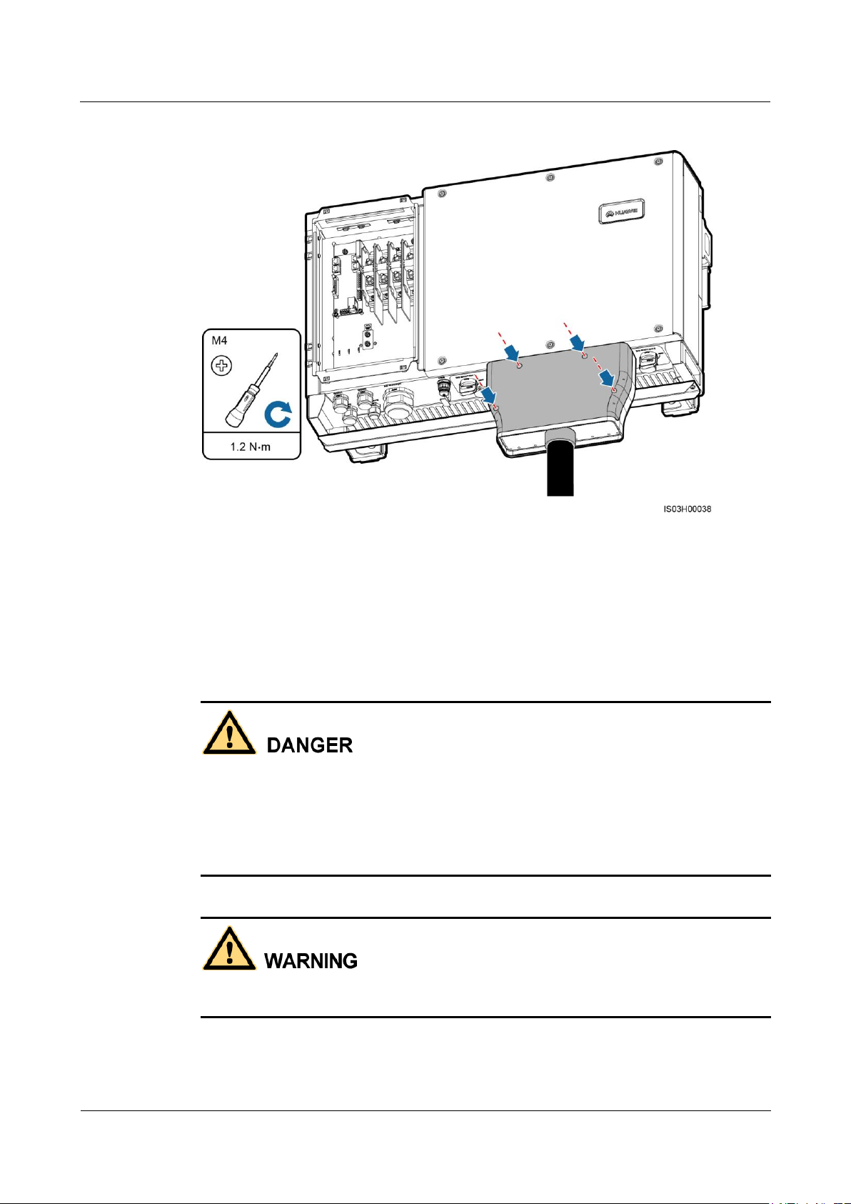
Figure 5-26 Installing a front cover
5.6 Connecting DC Input Power Cables
Prerequisites
Before connecting DC input power cables, ensure that the DC voltage is within the safe
range (lower than 60 V DC) and that the two DC switches on the SUN2000 are OFF.
Otherwise, the high voltage may result in electric shocks.
When the SUN2000 is grid-tied, it is not allowed to maintain DC input power cables, such
as connect or disconnect a string or a module in a string. Otherwise, electric shocks may
occur.
Ensure that the following conditions are met. Otherwise, the SUN2000 will be damaged, or
even a fire disaster will be caused.
Page 66

SUN2000-(33KTL, 36KTL, 40KTL)-US
User Manual
5 Connecting Cables
Issue 01 (2017-04-01)
Huawei Proprietary and Confidential
Copyright © Huawei Technologies Co., Ltd.
60
The highest open-circuit voltage of each PV string is always lower than or equal to 1000 V
DC.
The positive and negative terminals of a PV module connect to the positive and negative
DC input terminals of the SUN2000 respectively.
If the DC input power cable is reversely connected, do not operate the DC switches and
positive and negative connectors immediately. Wait until the solar irradiance declines at
night and the PV string current reduces to below 0.5 A. Then, turn off the two DC switches,
remove the positive and negative connectors, and correct the polarity of the DC input
power cable.
Ensure that the PV string is well insulated to the ground. If the SUN2000 is directly
connected to the power grid with a neutral wire connected to the PGND cable (for
example, a low-voltage power grid or a power grid with a neutral wire grounded), do not
ground the positive and negative terminals of PV strings. Otherwise, the SUN2000 may be
damaged. The caused equipment damage is beyond the warranty scope.
During the installation of PV strings and SUN2000, the positive or negative terminals of
PV strings may be grounded if power cables are not properly installed or routed. In this
case, an AC or DC short circuit may occur and damage the SUN2000. The caused
equipment damage is beyond the warranty scope.
Context
The PV strings must meet the following requirements if they need to be grounded:
A three-phase isolation transformer is installed on the output side.
One isolation transformer must be installed only for one SUN2000. Do not connect two or more
SUN2000s to the same isolation transformer. Otherwise, the SUN2000s may fail to work due to the
loop current generated between them.
Set Isolation to Input grounded, with TF on the SUN2000 APP, SmartLogger, or NMS.
DC terminal selection
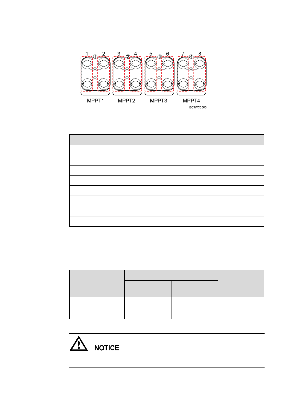
Figure 5-27 shows the DC terminals at the bottom of the SUN2000. Table 5-3 describes
the requirements for DC terminal selection.
The SUN2000 provides two DC switches, namely, DC SWITCH 1 and DC SWITCH 2. DC SWITCH 1
controls the first to fourth routes of DC input terminals, whereas DC SWITCH 2 controls the fifth to
eighth routes of DC input terminals.
Page 67
SUN2000-(33KTL, 36KTL, 40KTL)-US
User Manual
5 Connecting Cables
Issue 01 (2017-04-01)
Huawei Proprietary and Confidential
Copyright © Huawei Technologies Co., Ltd.
61
Figure 5-27 DC terminals
Number of Inputs
SUN2000
1
Connects to any route.
2
Connects to routes 1 and 5.
3
Connects to routes 1, 3, and 5.
4
Connects to routes 1, 3, 5, and 7.
5
Connects to routes 1, 2, 3, 5, and 7.
6
Connects to routes 1, 2, 3, 5, 6, and 7.
7
Connects to routes 1, 2, 3, 4, 5, 6, and 7.
8
Connects to routes 1, 2, 3, 4, 5, 6, 7, and 8.
Cable Type
Conductor Cross-Sectional Area
Cable Outer
Diameter
Range
Recommended
Value
Common PV cables in
the industry (model:
PV1-F)
12–10 AWG
12 AWG
4.5–7.8 mm
(0.18–0.31 in.)
Table 5-3 DC terminal selection requirements
DC input power cable specifications
Table 5-4 lists the recommended DC input power cable specifications.
Table 5-4 Recommended DC input power cable specifications
Rigid cables, such as armored cables, are not recommended, because poor contact may be
caused by the bending of the cables.
Page 68
SUN2000-(33KTL, 36KTL, 40KTL)-US
User Manual
5 Connecting Cables
Issue 01 (2017-04-01)
Huawei Proprietary and Confidential
Copyright © Huawei Technologies Co., Ltd.
62
Procedure
Step 1 Prepare positive and negative connectors.
Use the DC input terminals provided with the SUN2000. If the terminals are lost or
damaged, purchase DC input terminals of the appropriate model from Huawei or MC4,
Amphenol HH4, or Amphenol H4 DC input terminals from other vendors.
DC input terminals not of the previous models may be incompatible with the SUN2000,
which may cause serious consequences. The caused equipment damage is beyond the
warranty scope.
Page 69
SUN2000-(33KTL, 36KTL, 40KTL)-US
User Manual
5 Connecting Cables
Issue 01 (2017-04-01)
Huawei Proprietary and Confidential
Copyright © Huawei Technologies Co., Ltd.
63
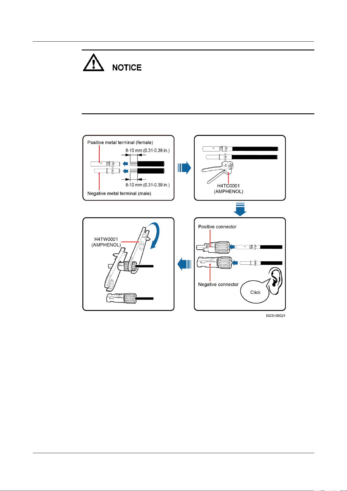
After crimping the positive and negative metal terminals, ensure that the cables are
crimped tightly such that they cannot be pulled out by a force less than 400 N.
Insert the crimped metal terminals of the positive and negative power cables into the
appropriate positive and negative connectors. Then pull back the DC input power cables to
ensure that they are connected securely.
Figure 5-28 Preparing a connector
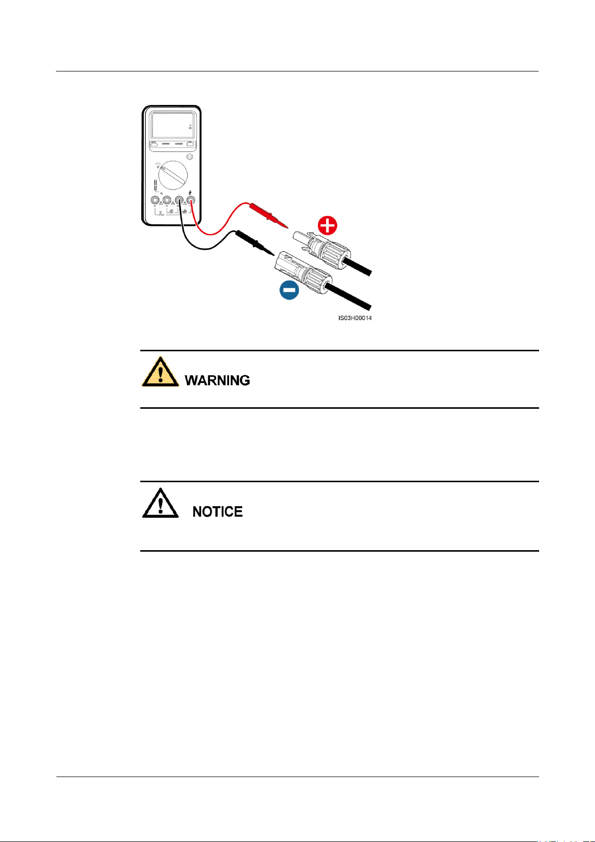
Step 2 Ensure that the DC input voltage of each PV string does not exceed 1000 V DC using a
multimeter and check that the polarities of the DC input power cable are correct.
If the voltage is a negative value, the PV string is reversely connected. Correct the
polarity.
If the voltage is greater than 1000 V DC, too many PV modules are configured. Remove
some PV modules.
Page 70
SUN2000-(33KTL, 36KTL, 40KTL)-US
User Manual
5 Connecting Cables
Issue 01 (2017-04-01)
Huawei Proprietary and Confidential
Copyright © Huawei Technologies Co., Ltd.
64
Figure 5-29 Measuring the DC input voltage
Before performing Step 3, ensure that the two DC switches are OFF.
Step 3 Remove the dustproof cap, and insert the positive and negative connectors into the
corresponding positive and negative DC input terminals of the SUN2000 until they snap into
place.
After the positive and negative connectors snap into place, pull the DC input power cables
back to ensure that they are connected securely.
Page 71
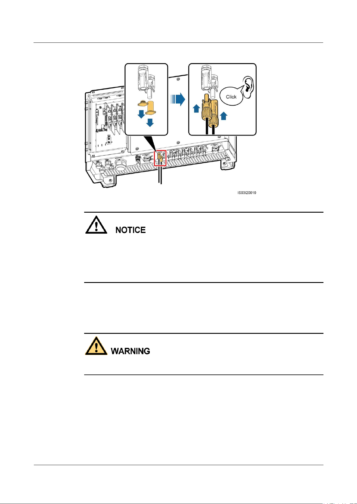
SUN2000-(33KTL, 36KTL, 40KTL)-US
User Manual
5 Connecting Cables
Issue 01 (2017-04-01)
Huawei Proprietary and Confidential
Copyright © Huawei Technologies Co., Ltd.
65
Figure 5-30 Connecting DC input power cables
If the DC input power cable is reversely connected, do not operate the DC switches and
positive and negative connectors immediately. Otherwise, the SUN2000 will be damaged. The
caused equipment damage is beyond the warranty scope. Wait until the solar irradiance
declines at night and the PV string current reduces to below 0.5 A. Then, turn off the two DC
switches, remove the positive and negative connectors, and correct the polarity of the DC
input power cable.
----End
Follow-up Procedure
Before removing the positive and negative connectors, ensure that the two DC switches are
OFF.
To remove the positive and negative connectors from the SUN2000, insert a removal wrench
into the notch and press the wrench with an appropriate force, as shown in Figure 5-31.
Page 72
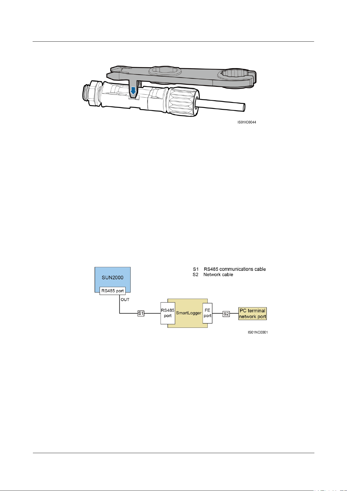
SUN2000-(33KTL, 36KTL, 40KTL)-US
User Manual
5 Connecting Cables
Issue 01 (2017-04-01)
Huawei Proprietary and Confidential
Copyright © Huawei Technologies Co., Ltd.
66
Figure 5-31 Removing a DC input connector
5.7 Connecting Communications Cables
5.7.1 Communication Mode Description
RS485 Communication
The SUN2000 can connect to the SmartLogger over RS485 or to a PC through the
SmartLogger to implement communication. You can use the SUN2000 APP, SmartLogger,
embedded WebUI, or the network management software (such as the NetEco) on the PC to
query information about the SUN2000, such as energy yield, alarms, and running status.
Figure 5-32 shows the communication mode for a single SUN2000.
Figure 5-32 Communication mode for a single SUN2000
Figure 5-33 shows the communication between multiple SUN2000s.
If multiple SUN2000s are used, connect all the SUN2000s in daisy chain mode over an
RS485 communications cable.
Page 73
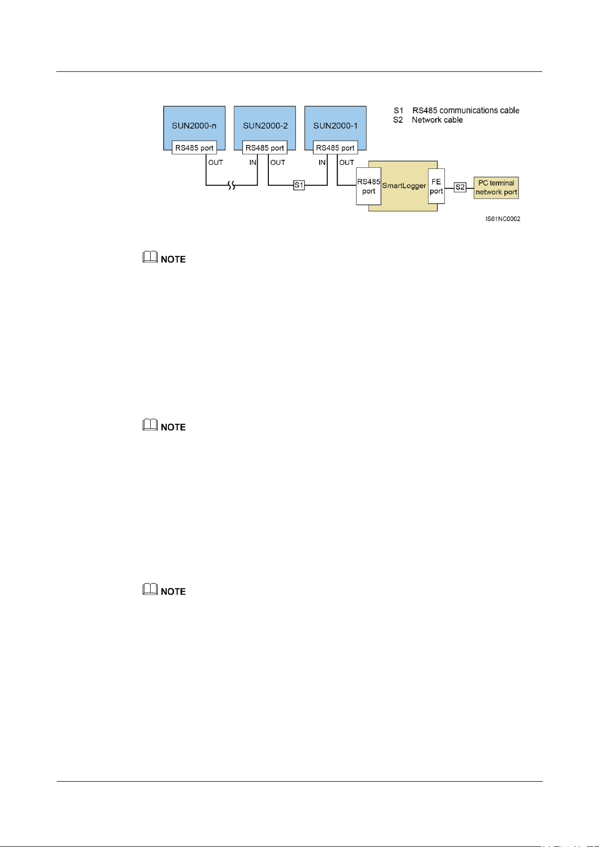
SUN2000-(33KTL, 36KTL, 40KTL)-US
User Manual
5 Connecting Cables
Issue 01 (2017-04-01)
Huawei Proprietary and Confidential
Copyright © Huawei Technologies Co., Ltd.
67
Figure 5-33 Communication mode for multiple SUN2000s
The RS485 communication distance between the SUN2000 at the end of the daisy chain and the
SmartLogger cannot exceed 1000 meters.
If multiple SUN2000s need to communicate with one another and are connected to a PC over the
SmartLogger2000, a maximum of six daisy chains can be configured.
To ensure the system response speed, it is recommended that the number of devices on each daisy
chain be less than 30.
PLC Communication
The PLC communication board loads communication signals onto power cables for
transmission. For details about how to install the PLC, see the PLC CCO01A User Manual
and SmartLogger2000 User Manual.
The built-in PLC module in the SUN2000 does not need to be connected with cables.
Selecting a Communication Mode
The RS485 and PLC communication modes are mutually exclusive.
If the PLC communication mode is selected, do not connect the RS485 communications
cable. In addition, you need to set PLC communication to Enable on the SUN2000
APP.
If the RS485 communication mode is selected, do not connect the PLC CCO module to
the AC power cable. In addition, you are recommended to set PLC communication to
Disable on the SUN2000 APP.
PLC communication is set to Enable by default.
5.7.2 Selecting a Mode for Connecting RS485 Communications Cables
Description
RRS485 communications cables can be connected in two ways:
− Terminal block connection
You are advised to use the DJYP2VP2-22 2x2x1 computer cable or a
communications cable with a conductor cross-sectional area of 18 AWG and an
outer diameter of 14–18 mm (0.55–0.71 in.).
Page 74
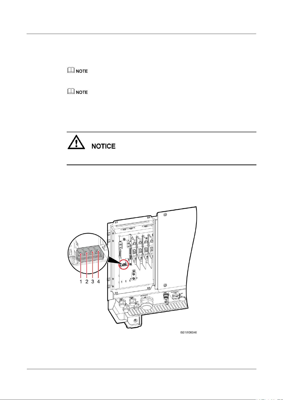
SUN2000-(33KTL, 36KTL, 40KTL)-US
User Manual
5 Connecting Cables
Issue 01 (2017-04-01)
Huawei Proprietary and Confidential
Copyright © Huawei Technologies Co., Ltd.
68
− RJ45 network port connection
You are advised to use a CAT 5E outdoor shielded network cable with an outer
diameter less than 9 mm (0.35 in.) and internal resistance not greater than 1.5
ohms/10 m (1.5 ohms/393.70 in.), as well as a shielded RJ45 connector.
Select either connection way in practice. Connecting to a terminal block is recommended.
The RS485 communications cable can be connected in a common way or through a pipe.
Before installation, prepare materials based on the connection mode.
If you choose connection through a pipe, ensure that the RS485 communications cable and 3/4–inch
pipe are available.
If you choose common connection, ensure that the RS485 communications cable is available.
When laying out communications cables, separate them from power cables and avoid large
signal interference sources to protect communication from being affected.
Terminal Block Pin Definitions
Figure 5-34 shows an RS485 terminal block.
Figure 5-34 Terminal block
Table 5-5 describes pin definitions of the RS485 terminal block.
Page 75
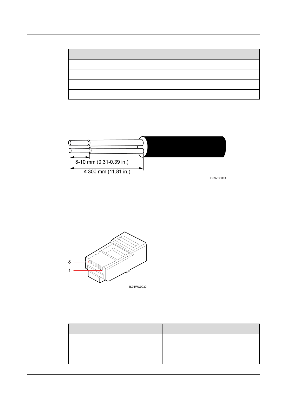
SUN2000-(33KTL, 36KTL, 40KTL)-US
User Manual
5 Connecting Cables
Issue 01 (2017-04-01)
Huawei Proprietary and Confidential
Copyright © Huawei Technologies Co., Ltd.
69
Table 5-5 Pin definitions of the RS485 terminal block
No.
Port Definition
Description
1
RS485A IN
RS485A, RS485 differential signal +
2
RS485A OUT
RS485A, RS485 differential signal +
3
RS485B IN
RS485B, RS485 differential signal –
4
RS485B OUT
RS485B, RS485 differential signal –
Pin
Color
Function
1
White-and-orange
RS485A, RS485 differential signal +
2
Orange
RS485B, RS485 differential signal –
3
White-and-green
N/A
Figure 5-35 shows how to prepare an RS485 communications cable.
Figure 5-35 Stripping an RS485 communications cable
RJ45 Connector Pin Definitions
Figure 5-36 shows an RJ45 connector.
Figure 5-36 RJ45 connector
Table 5-6 lists the RJ45 connector pin definitions.
Table 5-6 RJ45 connector pin definitions
Page 76
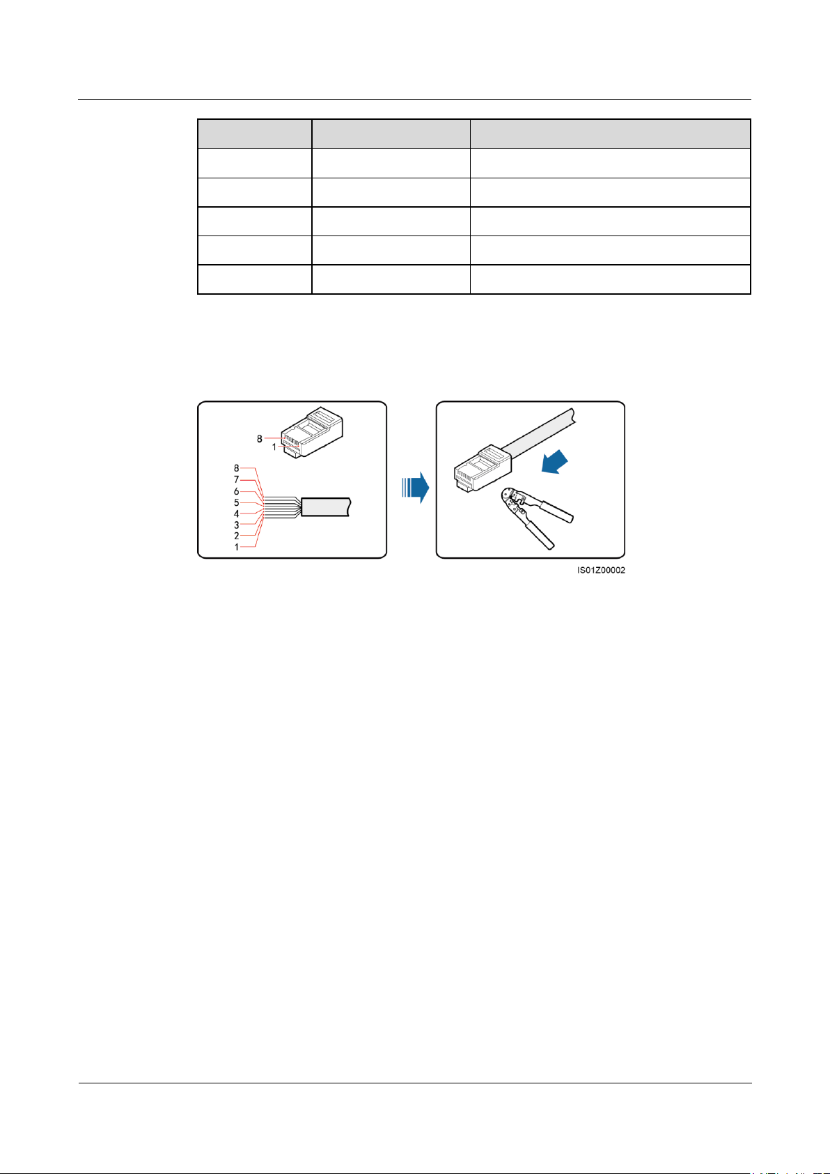
SUN2000-(33KTL, 36KTL, 40KTL)-US
User Manual
5 Connecting Cables
Issue 01 (2017-04-01)
Huawei Proprietary and Confidential
Copyright © Huawei Technologies Co., Ltd.
70
Pin
Color
Function
4
Blue
RS485A, RS485 differential signal +
5
White-and-blue
RS485B, RS485 differential signal –
6
Green
N/A
7
White-and-brown
N/A
8
Brown
N/A
(1) White-and-orange
(2) Orange
(3) White-and-green
(4) Blue
(5) White-and-blue
(6) Green
(7) White-and-brown
(8) Brown
Figure 5-37 shows how to prepare an RS485 communications cable.
Figure 5-37 Connecting wires to an RJ45 connector
5.7.3 Connecting RS485 Communications Cables Through a Pipe
Connecting Cables to the Terminal Block
Step 1 Install the pipe fittings.
1. Remove the locking caps and plugs from the waterproof connectors, and then remove the
waterproof connectors.
2. Secure the pipe fittings to the chassis using the nuts delivered with the pipes.
Page 77
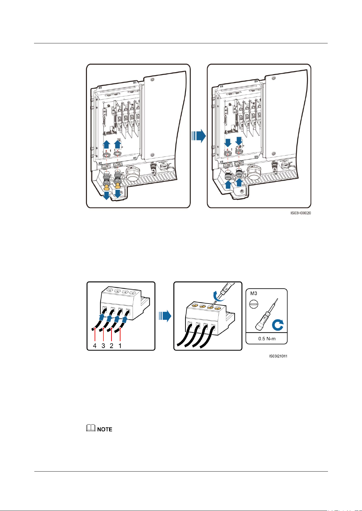
SUN2000-(33KTL, 36KTL, 40KTL)-US
User Manual
5 Connecting Cables
Issue 01 (2017-04-01)
Huawei Proprietary and Confidential
Copyright © Huawei Technologies Co., Ltd.
71
Figure 5-38 Installing pipe fittings
(1) RS485A IN
(2) RS485A OUT
(3) RS485B IN
(4) RS485B OUT
Step 2 Route the communications cables through the conduits and then fittings of the pipes.
Step 3 Remove the cable terminal base from the terminal block. Connect the communications cables
to the terminal base.
Figure 5-39 Connecting cables to a terminal base
Step 4 Install the terminal base on the terminal block, and connect the shield layers to the ground
point.
When connecting the shielded cables, choose whether to crimp the OT terminal based on site
requirements.
Page 78
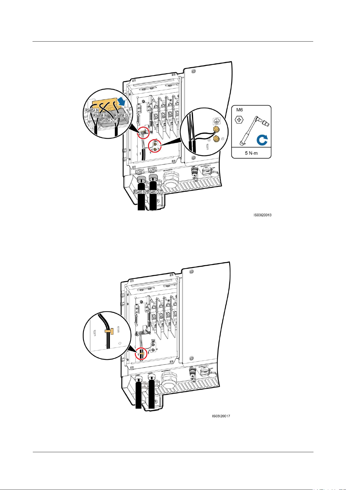
SUN2000-(33KTL, 36KTL, 40KTL)-US
User Manual
5 Connecting Cables
Issue 01 (2017-04-01)
Huawei Proprietary and Confidential
Copyright © Huawei Technologies Co., Ltd.
72
Figure 5-40 Connecting communications cables
Step 5 Bind communications cables after connecting them.
Figure 5-41 Binding communications cables
Page 79
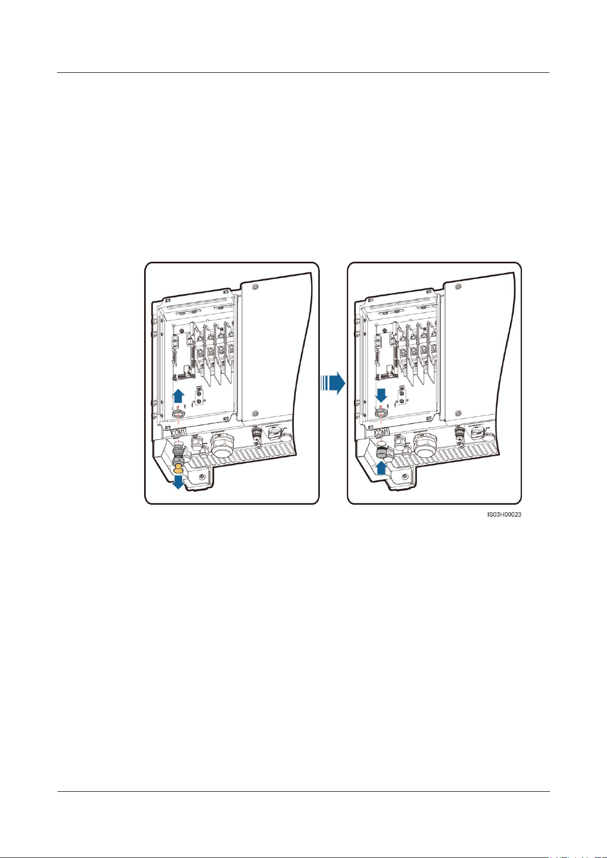
SUN2000-(33KTL, 36KTL, 40KTL)-US
User Manual
5 Connecting Cables
Issue 01 (2017-04-01)
Huawei Proprietary and Confidential
Copyright © Huawei Technologies Co., Ltd.
73
Step 6 Connect the conduits and fittings of the pipes.
----End
Connecting Cables to the RJ45 Network Port
Step 1 Install the pipe fitting.
1. Remove the locking cap and plug from the waterproof connector, and then remove the
waterproof connector.
2. Secure the pipe fitting to the chassis using the nut delivered with the pipe.
Figure 5-42 Installing pipe fitting
Step 2 Route the communications cables through the conduit and then fitting of the pipe.
Step 3 Insert the RJ45 connectors into the RJ45 network ports in the SUN2000 maintenance
compartment.
Page 80
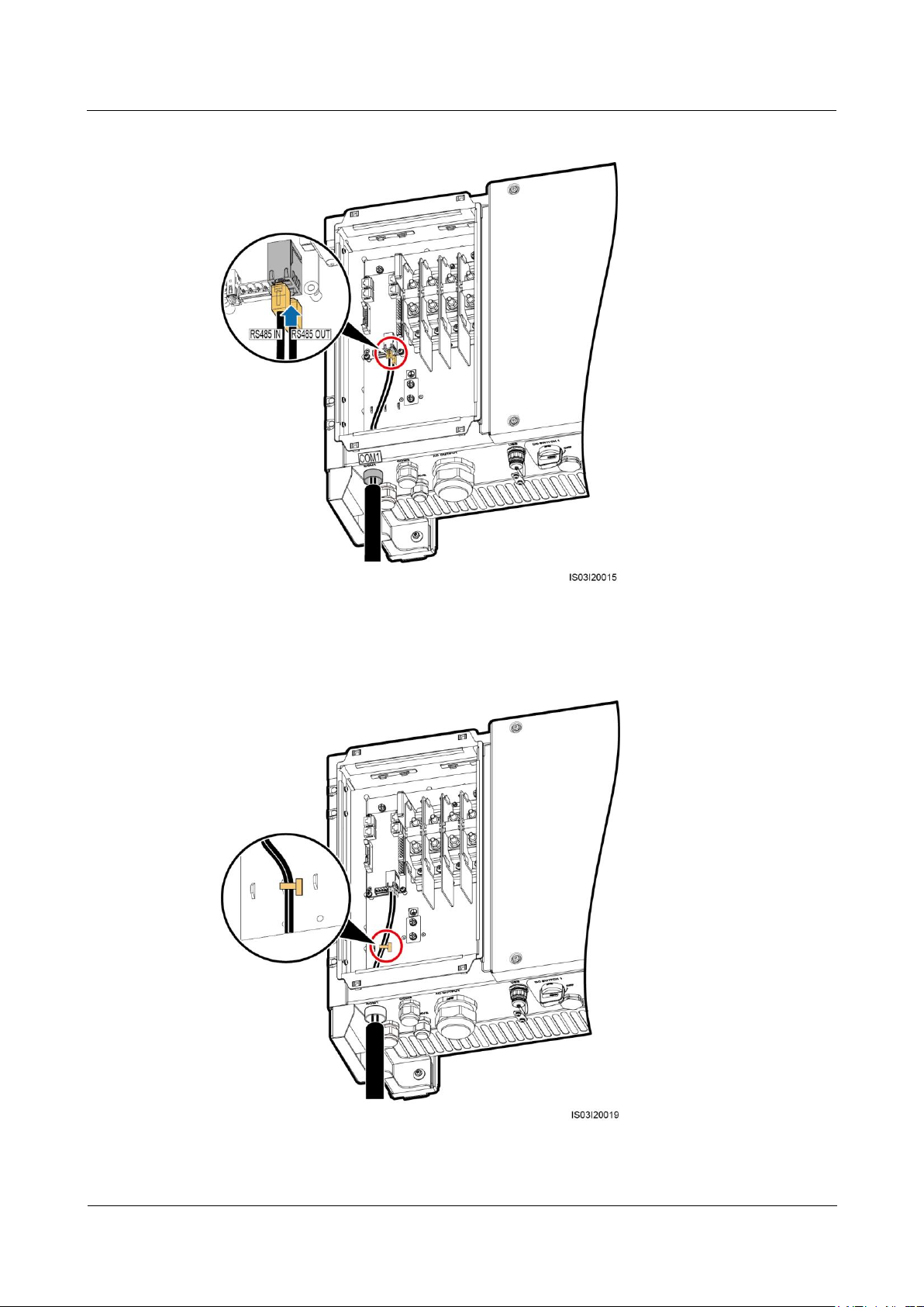
SUN2000-(33KTL, 36KTL, 40KTL)-US
User Manual
5 Connecting Cables
Issue 01 (2017-04-01)
Huawei Proprietary and Confidential
Copyright © Huawei Technologies Co., Ltd.
74
Figure 5-43 Connecting communications cables
Step 4 Bind communications cables after connecting them.
Figure 5-44 Binding communications cables
Page 81
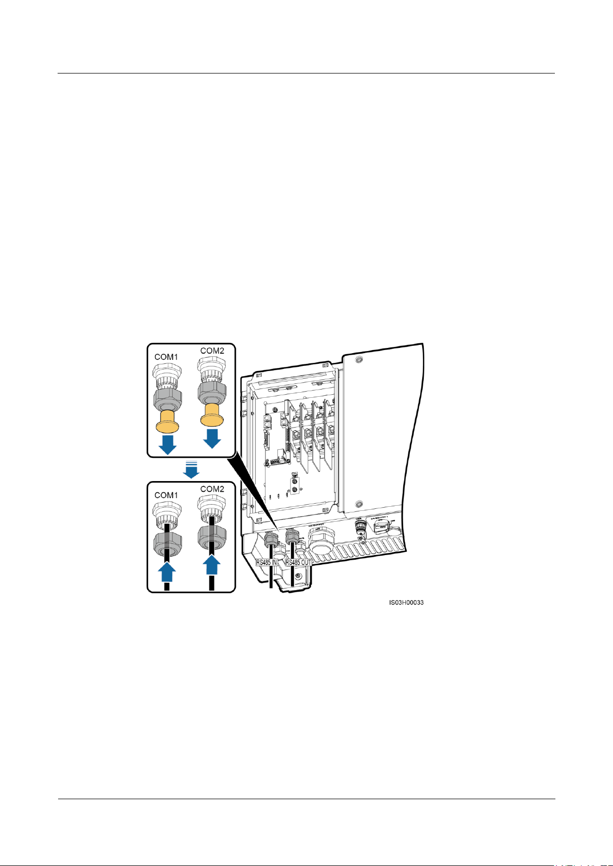
SUN2000-(33KTL, 36KTL, 40KTL)-US
User Manual
5 Connecting Cables
Issue 01 (2017-04-01)
Huawei Proprietary and Confidential
Copyright © Huawei Technologies Co., Ltd.
75
Step 5 Connect the conduit and fitting of the pipe.
----End
Follow-up Procedure
Check that the cables are connected correctly and securely. Then take appropriate measures to
ensure that the pipe conduit and fitting are secured reliably, and seal the cable hole using
firestop putty. Clear foreign matter from the maintenance compartment.
5.7.4 Connecting the RS485 Communications Cable in a Common Way
Connecting Cables to the Terminal Block
Step 1 Route the communications cables through the waterproof connectors.
Figure 5-45 Routing cables
Step 2 Remove the cable terminal base from the terminal block. Connect the communications cables
to the terminal base.
Page 82
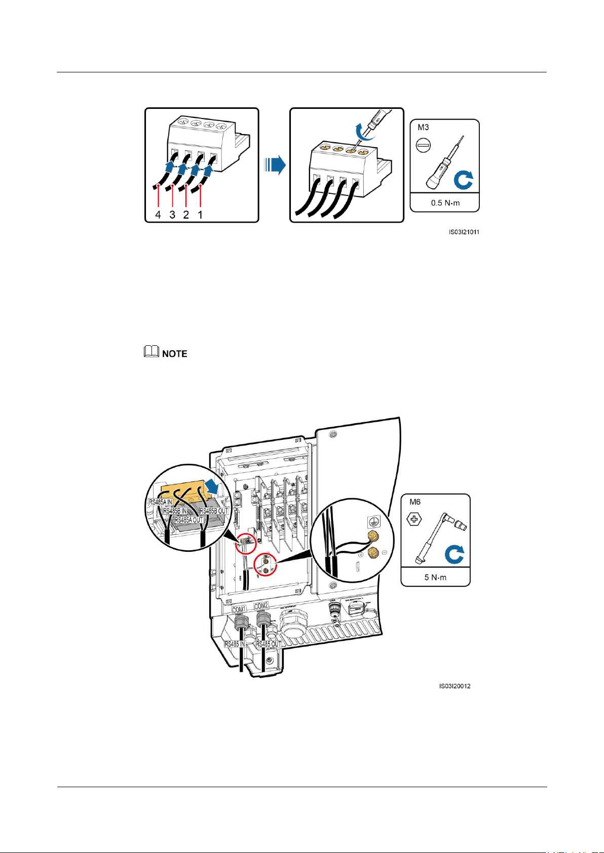
SUN2000-(33KTL, 36KTL, 40KTL)-US
User Manual
5 Connecting Cables
Issue 01 (2017-04-01)
Huawei Proprietary and Confidential
Copyright © Huawei Technologies Co., Ltd.
76
Figure 5-46 Connecting cables to a terminal base
(1) RS485A IN
(2) RS485A OUT
(3) RS485B IN
(4) RS485B OUT
Step 3 Install the terminal base on the terminal block, and connect the shield layers to the ground
point.
When connecting the shielded cables, choose whether to crimp the OT terminal based on site
requirements.
Figure 5-47 Connecting communications cables
Step 4 Bind communications cables after connecting them.
Page 83
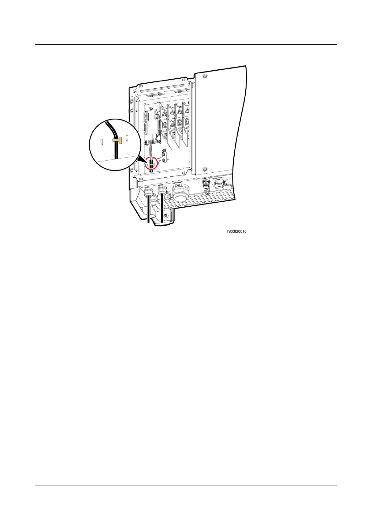
SUN2000-(33KTL, 36KTL, 40KTL)-US
User Manual
5 Connecting Cables
Issue 01 (2017-04-01)
Huawei Proprietary and Confidential
Copyright © Huawei Technologies Co., Ltd.
77
Figure 5-48 Binding communications cables
Step 5 Tighten the waterproof connectors to a torque of 7.5 N•m.
----End
Connecting Cables to the RJ45 Network Port
Step 1 Route the communications cables through the waterproof connector.
Page 84
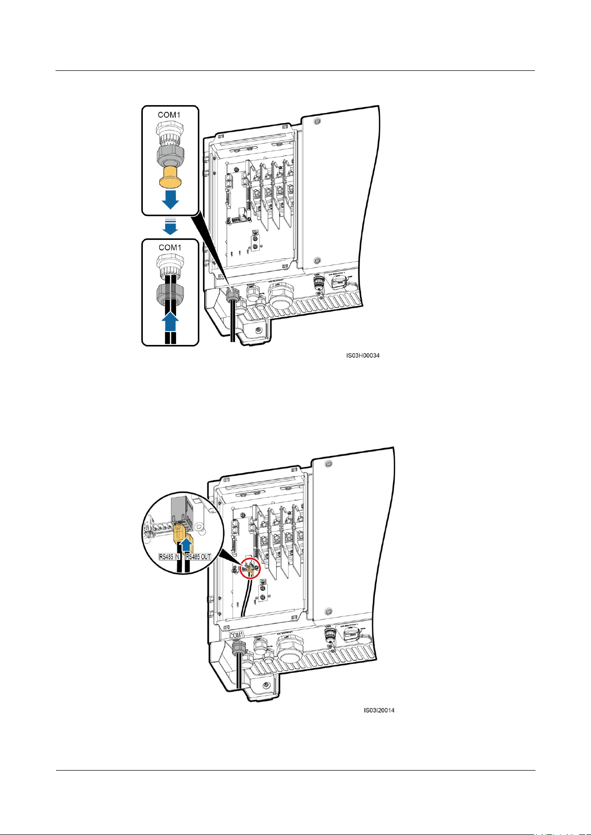
SUN2000-(33KTL, 36KTL, 40KTL)-US
User Manual
5 Connecting Cables
Issue 01 (2017-04-01)
Huawei Proprietary and Confidential
Copyright © Huawei Technologies Co., Ltd.
78
Figure 5-49 Routing cables
Step 2 Insert the RJ45 connectors into the RJ45 network ports in the SUN2000 maintenance
compartment.
Figure 5-50 Connecting communications cables
Page 85
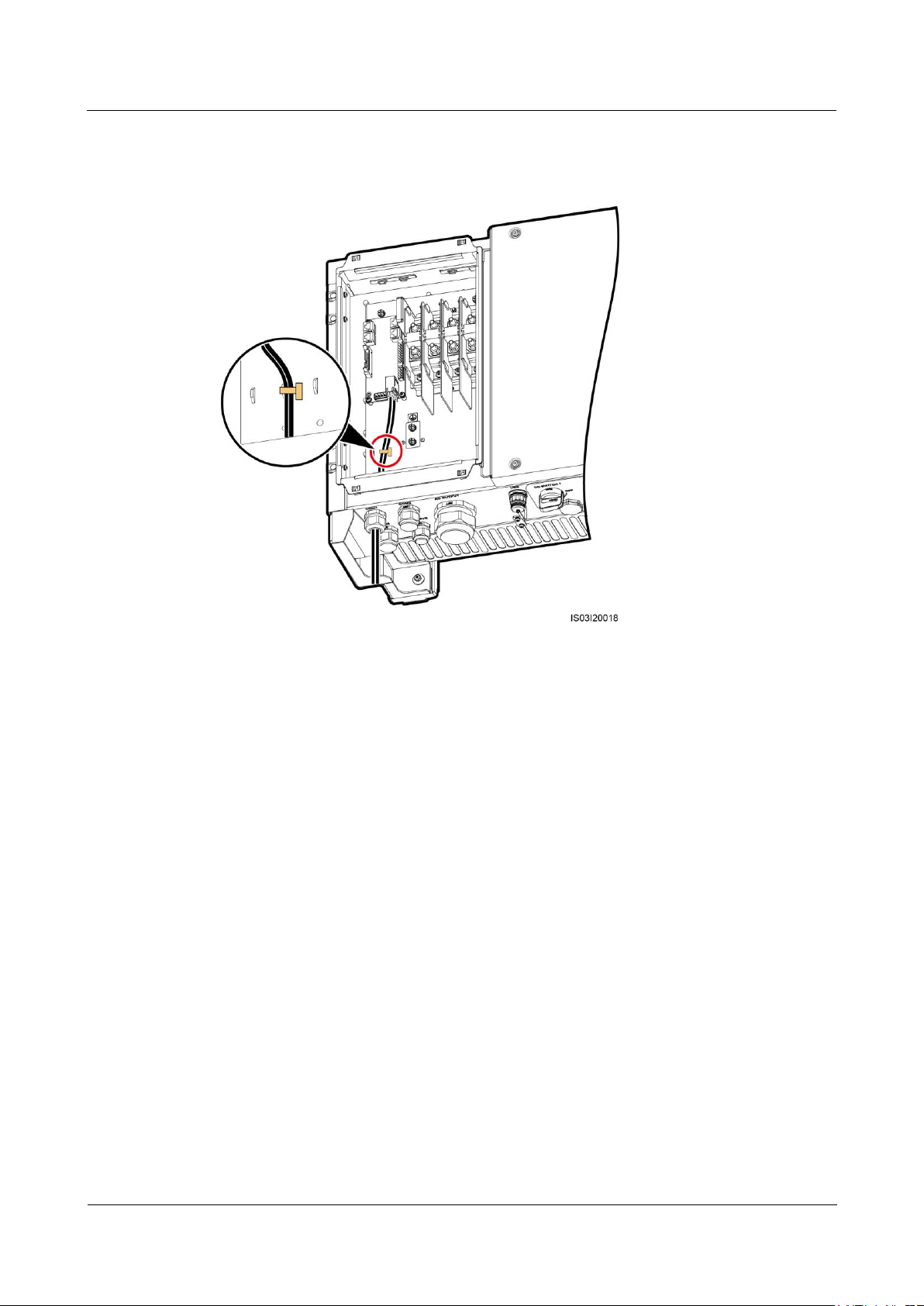
SUN2000-(33KTL, 36KTL, 40KTL)-US
User Manual
5 Connecting Cables
Issue 01 (2017-04-01)
Huawei Proprietary and Confidential
Copyright © Huawei Technologies Co., Ltd.
79
Step 3 Bind communications cables after connecting them.
Figure 5-51 Binding communications cables
Step 4 Tighten the waterproof connector to a torque of 7.5 N•m.
----End
Follow-up Procedure
Check that the cables are connected correctly and securely. Then apply firestop putty to the
waterproof connectors and cable holes. Clear foreign matter from the maintenance
compartment.
5.8 Closing the Maintenance Compartment Door
Procedure
Step 1 Install the AC terminal cover.
Page 86
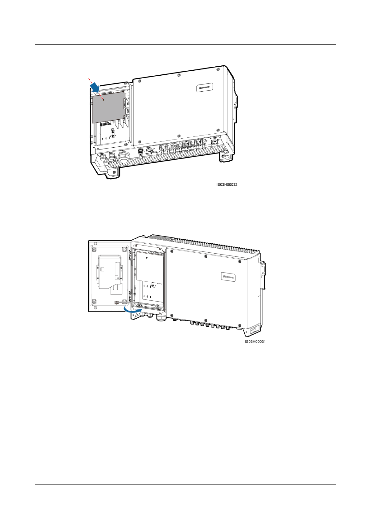
SUN2000-(33KTL, 36KTL, 40KTL)-US
User Manual
5 Connecting Cables
Issue 01 (2017-04-01)
Huawei Proprietary and Confidential
Copyright © Huawei Technologies Co., Ltd.
80
Figure 5-52 Installing a cover
Step 2 Adjust the support bar.
Figure 5-53 Adjusting a support bar
Step 3 Close the maintenance compartment door and tighten the two screws on the door.
Page 87
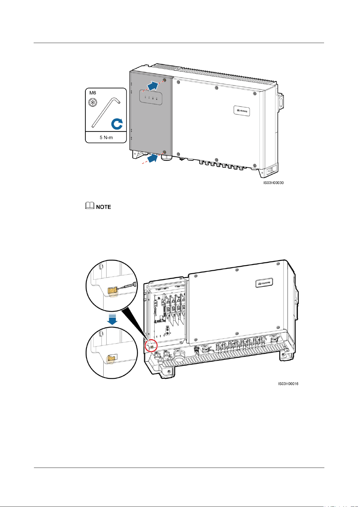
SUN2000-(33KTL, 36KTL, 40KTL)-US
User Manual
5 Connecting Cables
Issue 01 (2017-04-01)
Huawei Proprietary and Confidential
Copyright © Huawei Technologies Co., Ltd.
81
Figure 5-54 Tightening screws on the maintenance compartment door
If a screw on the maintenance compartment door is missing, use the unused ground screw on the
chassis shell as a standby screw.
If the floating nut used for securing the maintenance compartment door is missing, use the standby
floating nut shown in Figure 5-55.
Figure 5-55 Removing a standby floating nut
----End
Page 88

SUN2000-(33KTL, 36KTL, 40KTL)-US
User Manual
6 System Commissioning
Issue 01 (2017-04-01)
Huawei Proprietary and Confidential
Copyright © Huawei Technologies Co., Ltd.
82
6 System Commissioning
6.1 Checking Before Power-On
1. The SUN2000 is installed correctly and securely.
2. Check that the two DC switches at the bottom of the SUN2000 and the downstream AC
output switch are OFF.
3. No connected cable is damaged.
4. Ground cables are connected securely, without open circuits or short circuits.
5. AC output power cables are connected correctly and securely, without open circuits or
short circuits.
6. DC input power cables are connected correctly and securely, without open circuits or
short circuits.
7. The communications cables are connected correctly and securely.
8. All pipes or used waterproof connectors at the chassis bottom are applied with firestop
putty.
9. The AC terminal cover is reinstalled.
10. Check that the maintenance compartment is clean and tidy, without foreign matter.
11. The maintenance compartment door is closed and the door screws are tightened.
12. Idle DC input terminals are sealed.
13. The idle USB port is plugged with cover.
14. Idle RESERVE and COM waterproof connectors are plugged and the locking caps are
tightened.
6.2 Powering On the SUN2000
Prerequisites
Before turning on the AC switch between the SUN2000 and the power grid, use a multimeter
to check that the AC voltage is within the specified range.
Procedure
Step 1 Turn on the AC switch between the SUN2000 and the power grid.
Page 89
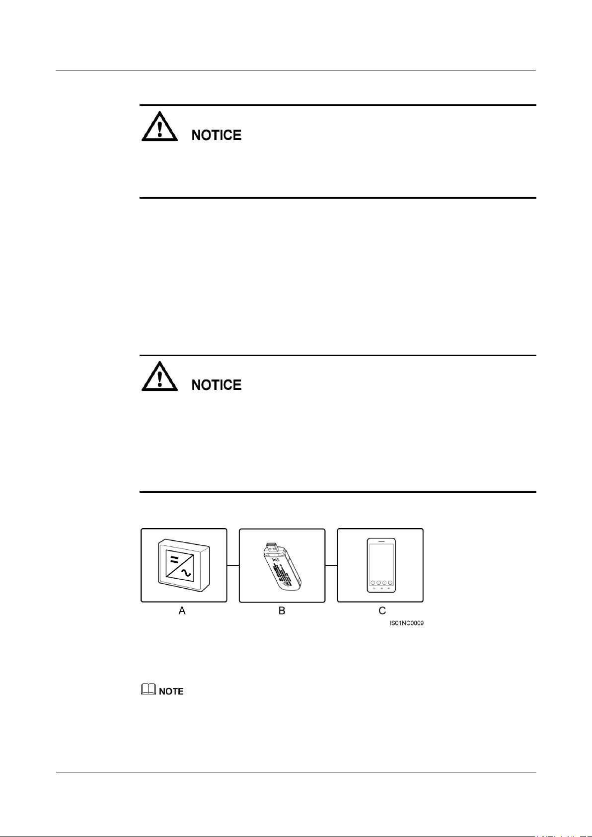
SUN2000-(33KTL, 36KTL, 40KTL)-US
User Manual
6 System Commissioning
Issue 01 (2017-04-01)
Huawei Proprietary and Confidential
Copyright © Huawei Technologies Co., Ltd.
83
(A) Inverter
(B) Bluetooth module
(C) Mobile phone
If you perform Step 2 before Step 1, the SUN2000 reports a fault about abnormal shutdown.
The SUN2000 can start normally after the fault is automatically rectified. The default alarm
clearance time is 1 minute. You can modify the time over the NMS software installed on the
PC that connects to the SUN2000.
Step 2 Turn on the DC switches at the bottom of the SUN2000 chassis.
Step 3 (Optional) Measure the temperatures at the joints between DC terminals and connectors using
a point-test thermometer.
To ensure that the DC terminals are in good contact, check the temperatures at the joints
between DC terminals and connectors after the SUN2000 has been running for a period of
time. Ensure that the temperature rise does not exceed 40°C (104°F).
Step 4 Connect the SUN2000 to the mobile phone that runs SUN2000 app (app for short) through a
Bluetooth module or USB data cable.
Mobile phone operating system: Android 4.0 or later, iOS 7.0 or later. When the iOS is
used, the app supports only Bluetooth connection.
When you use a Bluetooth module to set up the connection, ensure that the mobile phone
and SUN2000 are at most 5 meters (196.85 inches) away from each other. Otherwise, the
communication quality between them will deteriorate.
The screen snapshots in this document correspond to app V200R001C20SPC010
(Android).
Figure 6-1 Bluetooth module connection (Android and iOS)
Purchase the Bluetooth module bundled with the SUN2000. A Bluetooth module purchased from any
other source may not support communication between the SUN2000 and the app.
The Android system supports the Bluetooth module USB-Adapter2000-B and BF4030.
The iOS system supports the Bluetooth module USB-Adapter2000-B.
Page 90
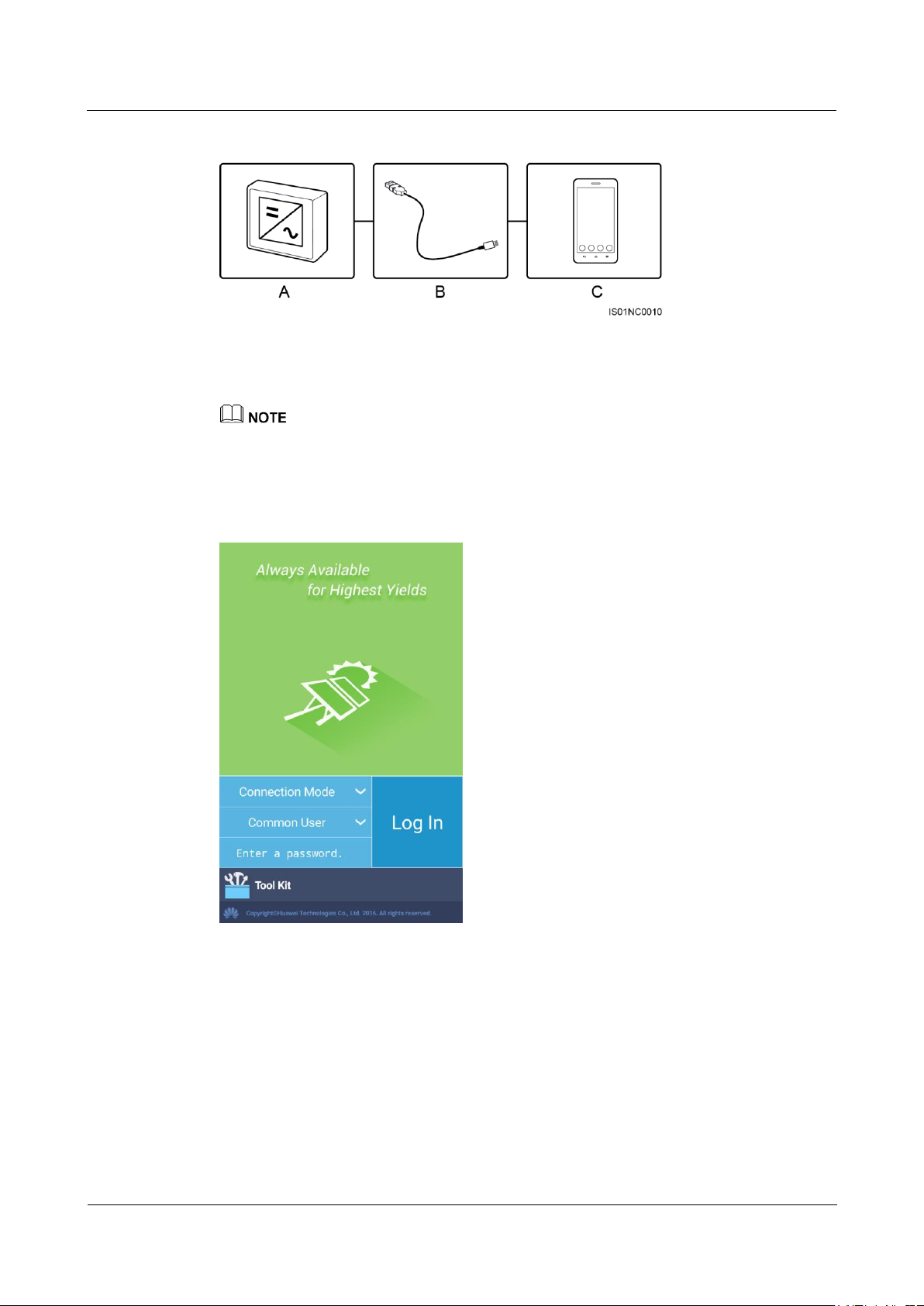
SUN2000-(33KTL, 36KTL, 40KTL)-US
User Manual
6 System Commissioning
Issue 01 (2017-04-01)
Huawei Proprietary and Confidential
Copyright © Huawei Technologies Co., Ltd.
84
Figure 6-2 Data cable connection (Android)
(A) Inverter
(B) USB data cable
(C) Mobile phone
Use the USB data cable delivered with the mobile phone.
The port type of the USB data cable connected to the SUN2000 is USB 2.0.
If the mobile phone provides a USB Type-C port, prepare a USB Type C to USB 2.0 adapter cable.
Figure 6-3 Login screen
Page 91
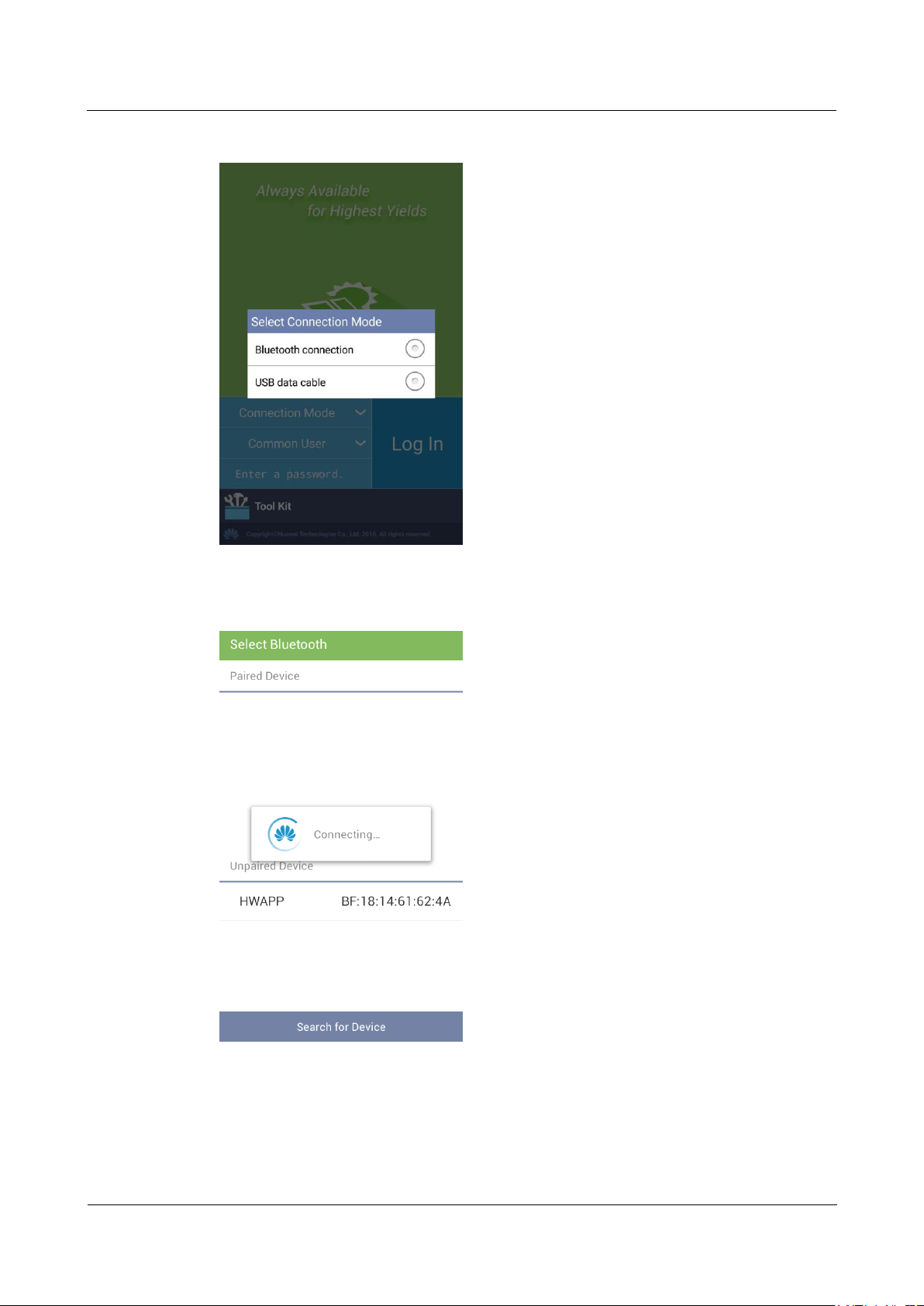
SUN2000-(33KTL, 36KTL, 40KTL)-US
User Manual
6 System Commissioning
Issue 01 (2017-04-01)
Huawei Proprietary and Confidential
Copyright © Huawei Technologies Co., Ltd.
85
Figure 6-4 Selecting a connection mode
Figure 6-5 Bluetooth connection
Page 92
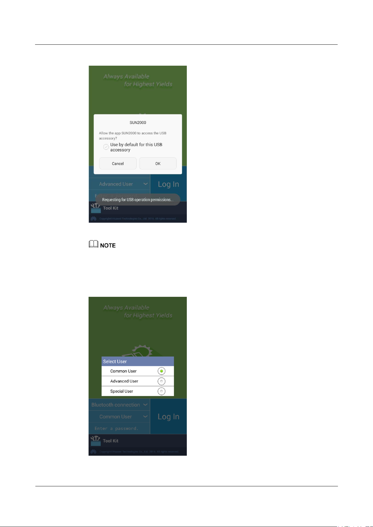
SUN2000-(33KTL, 36KTL, 40KTL)-US
User Manual
6 System Commissioning
Issue 01 (2017-04-01)
Huawei Proprietary and Confidential
Copyright © Huawei Technologies Co., Ltd.
86
Figure 6-6 Data cable connection
After you select Use by default for this USB accessory, the message will not appear if you connect the
app to the SUN2000 again without removing the USB data cable.
Step 5 Tap the user name area to switch between the common user, advanced user, and special user.
Figure 6-7 Switching between users
Page 93
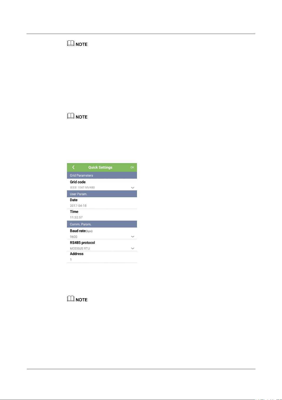
SUN2000-(33KTL, 36KTL, 40KTL)-US
User Manual
6 System Commissioning
Issue 01 (2017-04-01)
Huawei Proprietary and Confidential
Copyright © Huawei Technologies Co., Ltd.
87
The login password is the same as that for the SUN2000 connected to the app and is used only when
the SUN2000 connects to the app.
The initial passwords for Common User, Advanced User, and Special User are all 00000a. Use the
initial password upon first login. To ensure account security, change the password immediately after
login.
During the login, if an incorrect password is entered for five consecutive times (the interval between
two consecutive invalid password entries is less than 2 minutes), the account will be locked for 10
minutes. The password consists of six digits.
Step 6 Enter the password and tap Log In.
Step 7 After the successful login, the Quick Settings screen or Function Menu screen is displayed.
If you log in to the app after the device connects to the app for the first time or factory defaults are
restored, the Quick Settings screen will be displayed on which you can set basic parameters. After
the settings take effect, you can enter the main menu screen and modify the parameters on the
Settings screen. By default, the SUN2000 can be grid-tied and you do not have to set parameters.
You are advised to log in to the Quick Settings screen as an advanced user for parameter settings.
Figure 6-8 Quick Settings screen (logging in as an advanced user)
Set the power grid code that applies to the country or region where the power station is located and
the inverter model.
Set user parameters based on the current date and time.
Set Baud rate, RS485 protocol, and Address based on site requirements. Baud rate can be set to
4800, 9600, or 19200. RS485 protocol can be set to MODBUS RTU, and Address can be set to any
value in the range of 1 to 247.
When multiple SUN2000s communicate with the SmartLogger over RS485, the addresses for all the
SUN2000s on each RS485 route must be within the address range set on the SmartLogger and
cannot be duplicate. Otherwise, the communication will fail. In addition, the baud rates of all the
SUN2000s on each RS485 route must be consistent with the SmartLogger baud rate.
Page 94
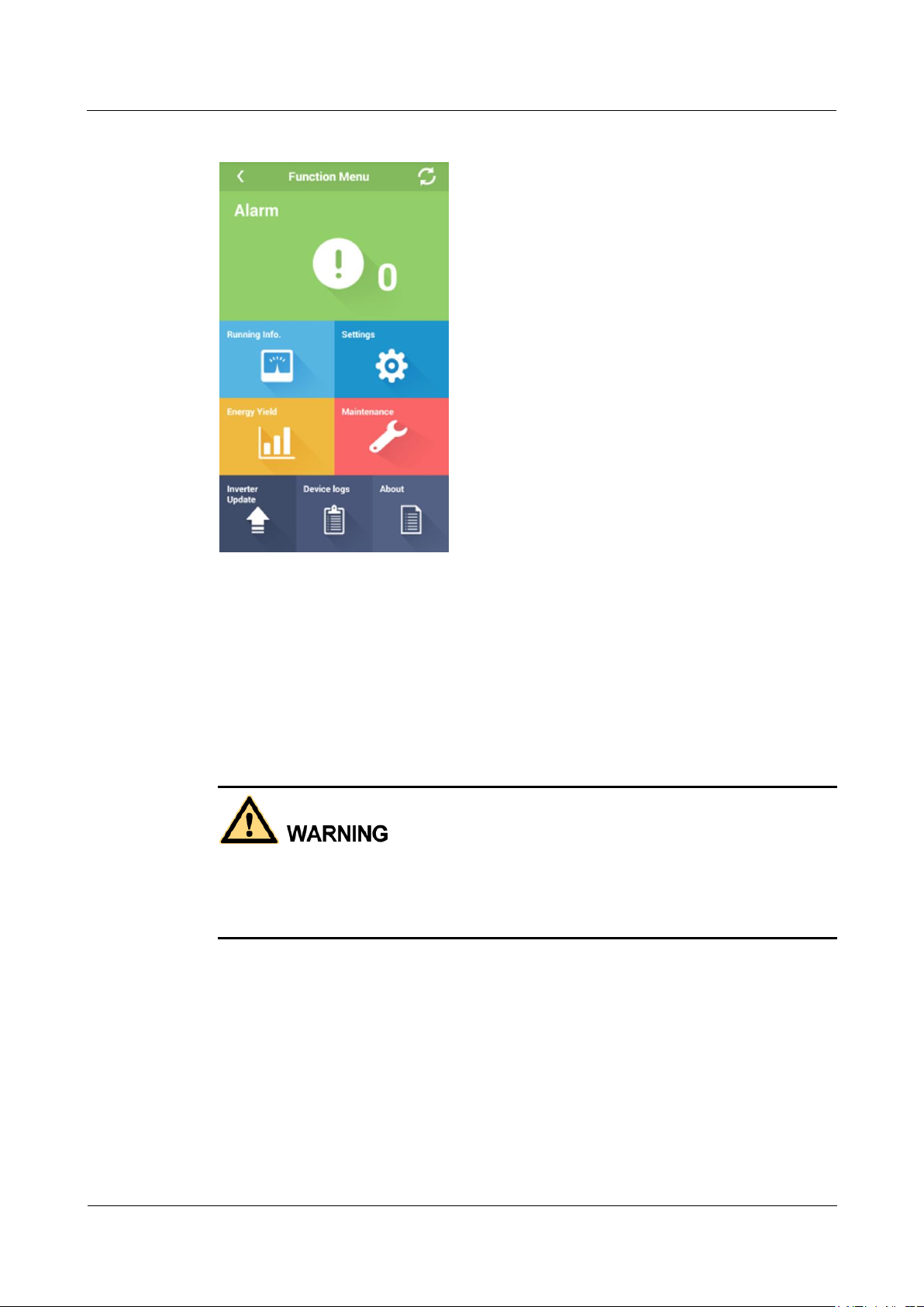
SUN2000-(33KTL, 36KTL, 40KTL)-US
User Manual
6 System Commissioning
Issue 01 (2017-04-01)
Huawei Proprietary and Confidential
Copyright © Huawei Technologies Co., Ltd.
88
Figure 6-9 Function Menu screen
----End
6.3 Powering Off the SUN2000
Context
If two SUN2000s share the same AC switch on the AC side, power off the two SUN2000s.
After the SUN2000 powers off, the remaining electricity and heat may still cause electric
shocks and body burns. Therefore, put on protective gloves and begin servicing the
SUN2000 five minutes after the power-off.
Procedure
Step 1 Run a shutdown command on the SUN2000 APP, SmartLogger, or NMS.
For details, see the SUN2000 APP User Manual, SmartLogger2000 User Manual, or
iManager NetEco 1000S User Manual.
Step 2 Turn off the AC switch between the SUN2000 and the power grid.
Step 3 Set the two DC switches to OFF.
Step 4 (Optional) Install locks on the DC switches.
Page 95
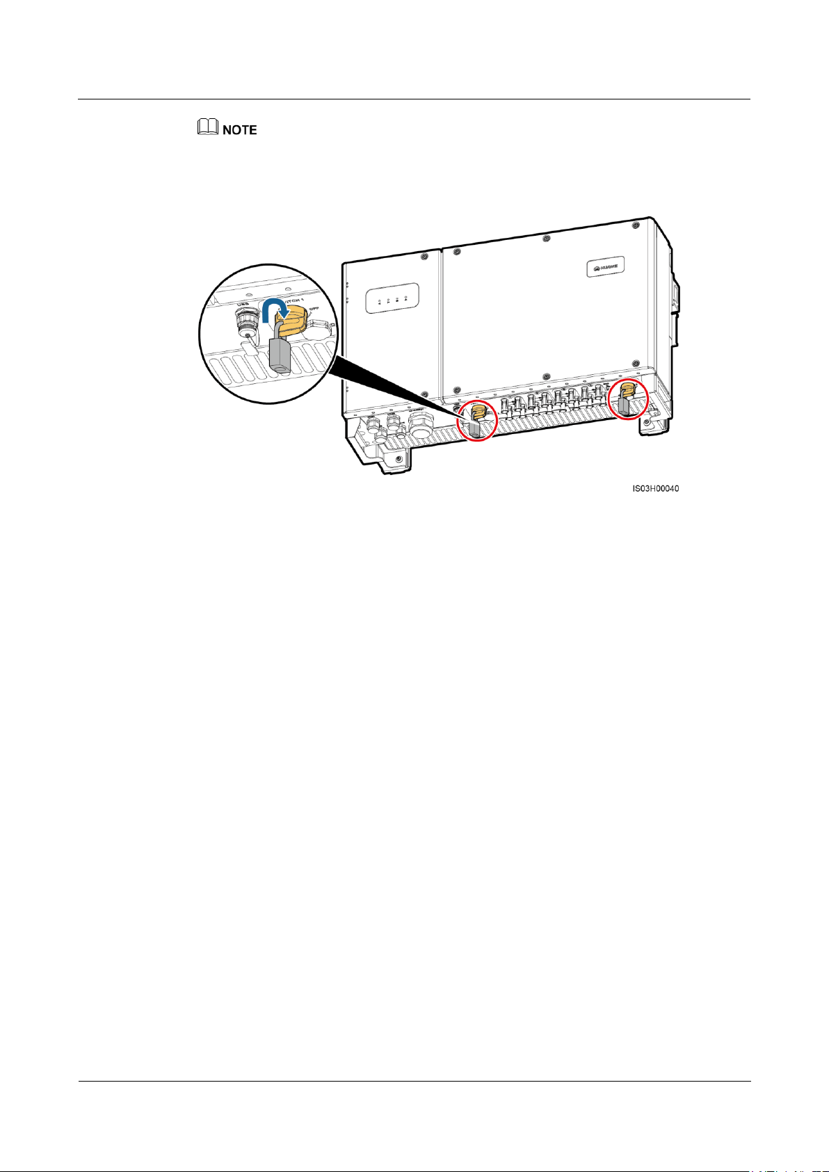
SUN2000-(33KTL, 36KTL, 40KTL)-US
User Manual
6 System Commissioning
Issue 01 (2017-04-01)
Huawei Proprietary and Confidential
Copyright © Huawei Technologies Co., Ltd.
89
Turn off the DC switches. To prevent turning on the switches by mistake, you are advised to lock the DC
switches.
Figure 6-10 Installing locks
----End
Page 96
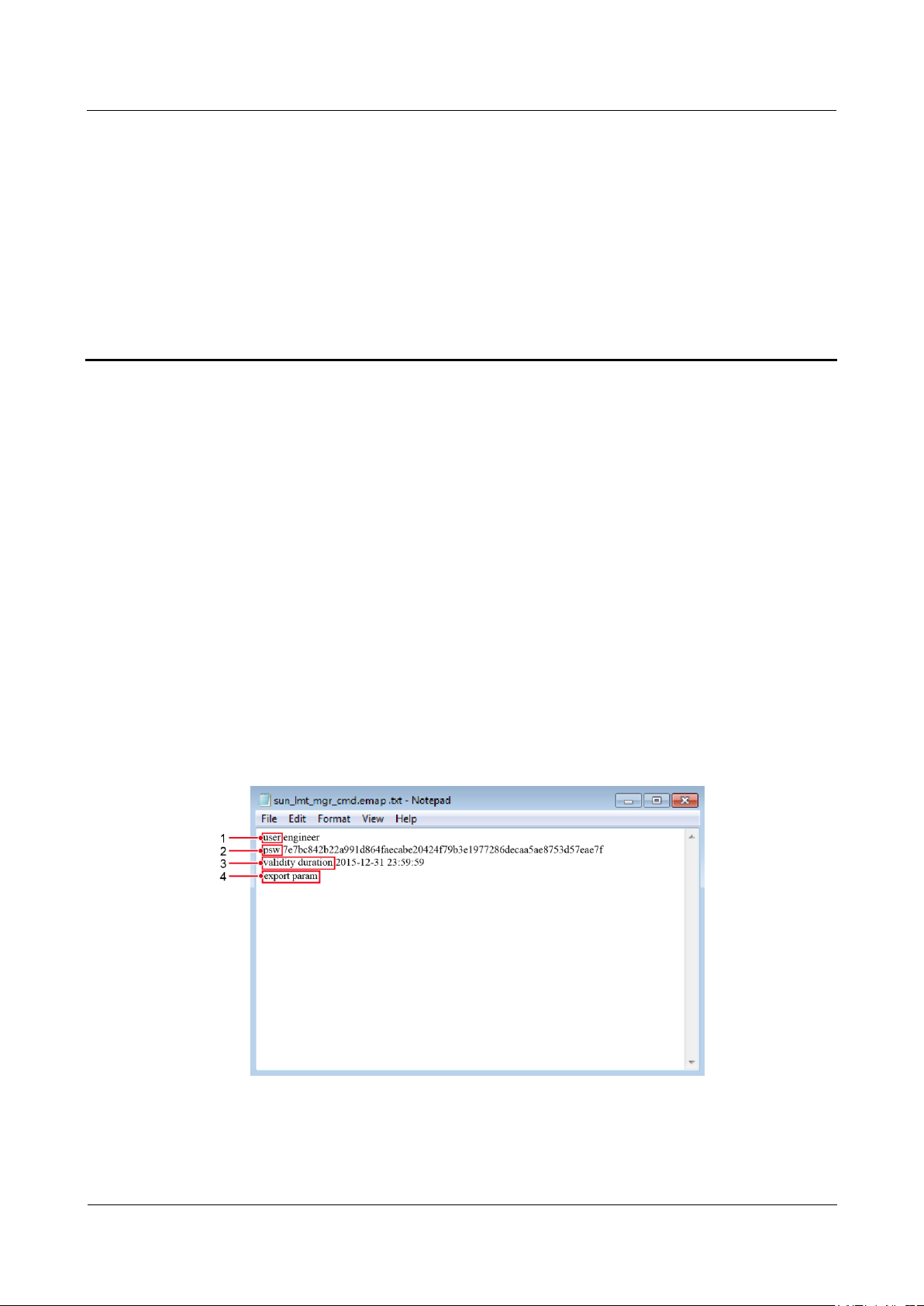
SUN2000-(33KTL, 36KTL, 40KTL)-US
User Manual
7 Man-Machine Interactions
Issue 01 (2017-04-01)
Huawei Proprietary and Confidential
Copyright © Huawei Technologies Co., Ltd.
90
7 Man-Machine Interactions
7.1 Operations with a USB Flash Drive
USB flash drives of SanDisk, Netac, and Kingston are recommended. Other brands may be
incompatible.
7.1.1 Exporting Configurations
Procedure
Step 1 Generate a boot script file by choosing Tool Kit > Local maintenance script > Inverter
Step 2 Import the boot script file to a PC.
maint script > Inverter Command Settings on the SUN2000 app. For details, see the
SUN2000 APP User Manual.
(Optional) The boot script file can be opened as a .txt file, as shown in Figure 7-1.
Figure 7-1 Boot script file
Page 97
SUN2000-(33KTL, 36KTL, 40KTL)-US
User Manual
7 Man-Machine Interactions
Issue 01 (2017-04-01)
Huawei Proprietary and Confidential
Copyright © Huawei Technologies Co., Ltd.
91
No.
Meaning
Remarks
1
User name
Advanced user: engineer
Special user: admin
2
Ciphertext
The ciphertext varies depending on the login password of the
SUN2000 APP.
3
Script validity
period
The script validity period varies depending on the script export
time.
4
Command
Different command settings can produce different commands.
Configuration export command: export param.
Configuration import command: import param.
Data export command: export log.
Upgrade command: upgrade.
LED Indicator
Status
Meaning
Green off
There is no operation with
a USB flash drive.
Blinking green at long intervals (on
for 1s and then off for 1s)
There is an operation with
a USB flash drive.
Blinking green at short intervals (on
for 0.125s and then off for 0.125s)
An operation with a USB
flash drive has failed.
Steady green
An operation with a USB
flash drive is successful.
Step 3 Import the boot script file to the root directory of a USB flash drive.
Step 4 Connect the USB flash drive to the USB port. The system automatically identifies the USB
flash drive and executes all commands specified in the boot script file. View the LED
indicator to determine the operating status.
Verify that the ciphertext in the boot script file matches the login password of the SUN2000
APP. If they do not match and you insert the USB flash drive for five consecutive times, the
user account will be locked for 10 minutes.
Table 7-1 LED indicator description
Step 5 Insert the USB flash drive into a computer and check the exported data.
Page 98
SUN2000-(33KTL, 36KTL, 40KTL)-US
User Manual
7 Man-Machine Interactions
Issue 01 (2017-04-01)
Huawei Proprietary and Confidential
Copyright © Huawei Technologies Co., Ltd.
92
LED Indicator
Status
Meaning
Green off
There is no operation with
a USB flash drive.
Blinking green at long intervals (on
for 1s and then off for 1s)
There is an operation with
a USB flash drive.
Blinking green at short intervals (on
for 0.125s and then off for 0.125s)
An operation with a USB
flash drive has failed.
When the configuration export is complete, the boot script file and exported file are in the root directory
of the USB flash drive.
----End
7.1.2 Importing Configurations
Prerequisites
A complete configuration file has been exported.
Procedure
Step 1 Generate a boot script file by choosing Tool Kit > Local maintenance script > Inverter
maint script > Inverter Command Settings on the SUN2000 app. For details, see the
SUN2000 APP User Manual.
Step 2 Import the boot script file to a PC.
Step 3 Replace the exported boot script file in the root directory of the USB flash drive with the
imported one.
Replace the boot script file only and keep the exported files.
Step 4 Connect the USB flash drive to the USB port. The system automatically identifies the USB
flash drive and executes all commands specified in the boot script file. View the LED
indicator to determine the operating status.
Verify that the ciphertext in the boot script file matches the login password of the SUN2000
APP. If they do not match and you insert the USB flash drive for five consecutive times, the
user account will be locked for 10 minutes.
Table 7-2 LED indicator description
Page 99
SUN2000-(33KTL, 36KTL, 40KTL)-US
User Manual
7 Man-Machine Interactions
Issue 01 (2017-04-01)
Huawei Proprietary and Confidential
Copyright © Huawei Technologies Co., Ltd.
93
LED Indicator
Status
Meaning
Steady green
An operation with a USB
flash drive is successful.
LED Indicator
Status
Meaning
Green off
There is no operation with
a USB flash drive.
Blinking green at long intervals (on
for 1s and then off for 1s)
There is an operation with
a USB flash drive.
Blinking green at short intervals (on
for 0.125s and then off for 0.125s)
An operation with a USB
flash drive has failed.
Steady green
An operation with a USB
flash drive is successful.
----End
7.1.3 Exporting Data
Procedure
Step 1 Generate a boot script file by choosing Tool Kit > Local maintenance script > Inverter
maint script > Inverter Command Settings on the SUN2000 app. For details, see the
SUN2000 APP User Manual.
Step 2 Import the boot script file to the root directory of a USB flash drive.
Step 3 Connect the USB flash drive to the USB port. The system automatically identifies the USB
flash drive and executes all commands specified in the boot script file. View the LED
indicator to determine the operating status.
Verify that the ciphertext in the boot script file matches the login password of the SUN2000
APP. If they do not match and you insert the USB flash drive for five consecutive times, the
user account will be locked for 10 minutes.
Table 7-3 LED indicator description
Step 4 Insert the USB flash drive into a PC and check the exported data.
After the data is exported, the boot script file and exported file are in the root directory of the USB flash
drive.
Page 100
SUN2000-(33KTL, 36KTL, 40KTL)-US
User Manual
7 Man-Machine Interactions
Issue 01 (2017-04-01)
Huawei Proprietary and Confidential
Copyright © Huawei Technologies Co., Ltd.
94
----End
Upgrade Method
Activation Start Condition
Local upgrade over a USB
flash drive
The CAN communication is normal.
The PV power supply is normal.
The activation starts when either of the preceding two
conditions is met.
Local upgrade of the SUN2000
APP
Remote upgrade over the
SmartLogger
The PV input voltage is greater than 500 V.
The output power is greater than 1 kW.
The activation starts when either of the preceding two
conditions is met.
Remote upgrade over the NMS
7.1.4 Upgrading
Context
Upgrade delay is mainly used in the upgrade scenarios where the PV power supply is
disconnected at night due to no solar radiation or unstable at dawn or dusk due to poor solar
radiation.
After the SUN2000 upgrade starts, if Upgrade delay is set to Enable, the upgrade package is
loaded first. After the PV power supply recovers and the activation conditions are met, the
SUN2000 automatically activates the upgrade.
Upgrade delay is set to Enable by default, which means that the upgrade can take place at day or night.
After enabling Upgrade delay, start the SUN2000 upgrade over the USB, SmartLogger, or NMS. The
SUN2000 upgrade process contains the following two stages:
1.
2.
Table 7-4 Conditions for starting delayed activation
The monitoring component caches and loads the upgrade package.
Upgrade package activation starts when the following conditions are met.
When upgrading the SUN2000 remotely, do not perform local operations for the SUN2000.
If the SUN2000 needs to be upgraded when the PV power supply is unavailable at night due to no
solar radiation or unstable at dawn or dusk due to poor solar radiation, ensure that the SUN2000 AC
output connects to the power grid.
Procedure
Step 1 Log in to http://support.huawei.com/carrier/ and browse or search for SUN2000 on the
Product Support tab page. Download the required upgrade package (for example, SUN2000
V200R002C20SPCXXX) from the Software tab page.
Step 2 Decompress the upgrade package.
After obtaining the upgrade package SUN2000V200R002C20SPCXXX_package.zip,
decompress it and ensure that the extracted files include:
 Loading...