

HUAWEI SUN2000-20KTL, SUN2000-29.9KTL, SUN2000- 30KTL, SUN2000- 36KTL, SUN2000- 40KTL User Manual
SUN2000-(20KTL, 29.9KTL, 30KTL, 36KTL, 40KTL)M3
User Manual
Issue 01
Date 2020-10-15
HUAWEI TECHNOLOGIES CO., LTD.
Copyright © Huawei Technologies Co., Ltd. 2020. All rights reserved.
No part of this document may be reproduced or transmitted in any form or by any means without prior
written consent of Huawei Technologies Co., Ltd.
Trademarks and Permissions
and other Huawei trademarks are trademarks of Huawei Technologies Co., Ltd.
All other trademarks and trade names mentioned in this document are the property of their respective
holders.
Notice
The purchased products, services and features are stipulated by the contract made between Huawei and
the customer. All or part of the products, services and features described in this document may not be
within the purchase scope or the usage scope. Unless otherwise specied in the contract, all statements,
information, and recommendations in this document are provided "AS IS" without warranties, guarantees
or representations of any kind, either express or implied.
The information in this document is subject to change without notice. Every eort has been made in the
preparation of this document to ensure accuracy of the contents, but all statements, information, and
recommendations in this document do not constitute a warranty of any kind, express or implied.
Huawei Technologies Co., Ltd.
Address: Huawei Industrial Base
Bantian, Longgang
Shenzhen 518129
People's Republic of China
Website: https://e.huawei.com
Issue 01 (2020-10-15) Copyright © Huawei Technologies Co., Ltd. i
SUN2000-(20KTL, 29.9KTL, 30KTL, 36KTL, 40KTL)M3
User Manual About this Document
About this Document
Overview
This document describes the SUN2000-20KTL-M3, SUN2000-29.9KTL-M3,
SUN2000-30KTL-M3, SUN2000-36KTL-M3, and SUN2000-40KTL-M3 (SUN2000 for
short) in terms of their installation, electrical connections, commissioning,
maintenance, and troubleshooting. Before installing and operating the SUN2000,
ensure that you are familiar with the features, functions, and safety precautions
provided in this document.
Intended Audience
This document is applicable to:
● Installers
● Users
Symbol Conventions
The symbols that may be found in this document are
Symbol
dened as follows.
Remarks
Indicates a hazard with a high level of risk
which, if not avoided, will result in death or
serious injury.
Indicates a hazard with a medium level of risk
which, if not avoided, could result in death or
serious injury.
Indicates a hazard with a low level of risk
which, if not avoided, could result in minor or
moderate injury.
Issue 01 (2020-10-15) Copyright © Huawei Technologies Co., Ltd. ii
SUN2000-(20KTL, 29.9KTL, 30KTL, 36KTL, 40KTL)M3
User Manual About this Document
Symbol Remarks
Indicates a potentially hazardous situation
which, if not avoided, could result in
equipment damage, data loss, performance
deterioration, or unanticipated results.
NOTICE is used to address practices not related
to personal injury.
Supplements the important information in the
main text.
NOTE is used to address information not
related to personal injury, equipment damage,
and environment deterioration.
Change History
Changes between document issues are cumulative. The latest document issue
contains all changes made in earlier issues.
Issue 01 (2020-10-15)
This issue is the rst ocial release.
Issue 01 (2020-10-15) Copyright © Huawei Technologies Co., Ltd. iii

SUN2000-(20KTL, 29.9KTL, 30KTL, 36KTL, 40KTL)M3
User Manual Contents
Contents
About this Document................................................................................................................. ii
1 Safety Information.................................................................................................................. 1
1.1 General Safety.......................................................................................................................................................................... 1
1.2 Personnel Requirements....................................................................................................................................................... 2
1.3 Electrical Safety........................................................................................................................................................................3
1.4 Installation Environment Requirements.......................................................................................................................... 4
1.5 Mechanical Safety................................................................................................................................................................... 4
1.6 Commissioning......................................................................................................................................................................... 5
1.7 Maintenance and Replacement..........................................................................................................................................6
2 Overview....................................................................................................................................7
2.1 Overview.................................................................................................................................................................................... 7
2.2 Appearance................................................................................................................................................................................9
2.3 Label Description.................................................................................................................................................................. 10
2.4 Working Principles................................................................................................................................................................ 12
2.4.1 Circuit Diagram.................................................................................................................................................................. 12
2.4.2 Working Modes.................................................................................................................................................................. 13
3 SUN2000 Storage...................................................................................................................15
4 Installation..............................................................................................................................16
4.1 Checking Before Installation............................................................................................................................................. 16
4.2 Tool Preparation.................................................................................................................................................................... 17
4.3 Selecting an Installation Position.................................................................................................................................... 18
4.4 Moving the SUN2000.......................................................................................................................................................... 21
4.5 Installing the Mounting Bracket...................................................................................................................................... 22
4.5.1 Support-mounted Installation.......................................................................................................................................23
4.5.2 Wall-mounted Installation............................................................................................................................................. 24
4.6 Installing a SUN2000........................................................................................................................................................... 25
5 Electrical Connections.......................................................................................................... 27
5.1 Precautions.............................................................................................................................................................................. 27
5.2 Preparing Cables................................................................................................................................................................... 28
5.3 Connecting the PE Cable.................................................................................................................................................... 30
5.4 Connecting the AC Output Power Cable...................................................................................................................... 32
Issue 01 (2020-10-15) Copyright © Huawei Technologies Co., Ltd. iv

SUN2000-(20KTL, 29.9KTL, 30KTL, 36KTL, 40KTL)M3
User Manual Contents
5.5 Installing the DC Input Power Cable.............................................................................................................................. 34
5.6 (Optional) Installing the Smart Dongle........................................................................................................................ 37
5.7 Connecting the Signal Cable............................................................................................................................................. 39
5.7.1 Communication Modes................................................................................................................................................... 41
5.7.2 (Optional) Connecting the RS485 Communications Cable to the SUN2000............................................... 42
5.7.3 (Optional) Connecting the RS485 Communications Cable to the Power Meter.........................................43
5.7.4 (Optional) Connecting the Power Grid Scheduling Signal Cable..................................................................... 44
5.7.5 (Optional) Connecting the Rapid Shutdown Signal Cable................................................................................. 45
6 Commissioning.......................................................................................................................47
6.1 Checking Before Power-On................................................................................................................................................47
6.2 System Power-On................................................................................................................................................................. 48
7 Man-Machine Interaction....................................................................................................50
7.1 Scenario in Which SUN2000s Are Connected to the FusionSolar Smart PV Management System.........51
7.1.1 (Optional) Registering an Installer Account............................................................................................................ 51
7.1.2 Creating a PV Plant and a User.................................................................................................................................... 52
7.1.3 SmartLogger Networking Scenario............................................................................................................................. 52
7.2 Scenario in Which SUN2000s Are Connected to Other Management Systems..............................................53
8 Maintenance...........................................................................................................................54
8.1 System Power-O.................................................................................................................................................................54
8.2 Routine Maintenance.......................................................................................................................................................... 55
8.3 Troubleshooting..................................................................................................................................................................... 55
9 Handling the Inverter...........................................................................................................66
9.1 Removing the SUN2000..................................................................................................................................................... 66
9.2 Packing the SUN2000..........................................................................................................................................................66
9.3 Disposing of the SUN2000................................................................................................................................................ 66
10 Technical
Specications.....................................................................................................67
A Grid Code................................................................................................................................ 73
B Device Commissioning......................................................................................................... 76
C Setting Power Adjustment Parameters........................................................................... 79
D Built-in PID Recovery........................................................................................................... 80
E Rapid Shutdown.................................................................................................................... 82
F Resetting Password...............................................................................................................83
G Setting Dry Contact Scheduling Parameters..................................................................84
H AFCI.......................................................................................................................................... 85
I Smart I-V Curve Diagnosis....................................................................................................88
J Acronyms and Abbreviations...............................................................................................89
Issue 01 (2020-10-15) Copyright © Huawei Technologies Co., Ltd. v

SUN2000-(20KTL, 29.9KTL, 30KTL, 36KTL, 40KTL)M3
User Manual 1 Safety Information
1 Safety Information
1.1 General Safety
Statement
Before installing, operating, and maintaining the equipment, read this document
and observe all the safety instructions on the equipment and in this document.
The "NOTICE", "CAUTION", "WARNING", and "DANGER" statements in this
document do not cover all the safety instructions. They are only supplements to
the safety instructions. Huawei will not be liable for any consequence caused by
the violation of general safety requirements or design, production, and usage
safety standards.
Ensure that the equipment is used in environments that meet its design
specications. Otherwise, the equipment may become faulty, and the resulting
equipment malfunction, component damage, personal injuries, or property
damage are not covered under the warranty.
Follow local laws and regulations when installing, operating, or maintaining the
equipment. The safety instructions in this document are only supplements to local
laws and regulations.
Huawei will not be liable for any consequences of the following circumstances:
● Operation beyond the conditions
● Installation or use in environments which are not
international or national standards
● Unauthorized modications to the product or software code or removal of the
product
● Failure to follow the operation instructions and safety precautions on the
product and in this document
● Equipment damage due to force majeure, such as earthquakes, re, and
storms
● Damage caused during transportation by the customer
● Storage conditions that do not meet the requirements specied in this
document
specied in this document
specied in relevant
Issue 01 (2020-10-15) Copyright © Huawei Technologies Co., Ltd. 1

D ANGER
SUN2000-(20KTL, 29.9KTL, 30KTL, 36KTL, 40KTL)M3
User Manual 1 Safety Information
General Requirements
Do not work with power on during installation.
● Do not install, use, or operate outdoor equipment and cables (including but
not limited to moving equipment, operating equipment and cables, inserting
connectors to or removing connectors from signal ports connected to outdoor
facilities, working at heights, and performing outdoor installation) in harsh
weather conditions such as lightning, rain, snow, and level 6 or stronger wind.
● After installing the equipment, remove idle packing materials such as cartons,
foam, plastics, and cable ties from the equipment area.
● In the case of a
● Do not scrawl, damage, or block any warning label on the equipment.
● Tighten the screws using tools when installing the equipment.
● Understand the components and functioning of a grid-tied PV power system
● Repaint any paint scratches caused during equipment transportation or
● Do not open the host panel of the equipment.
Personal Safety
● If there is a probability of personal injury or equipment damage during
● Use tools correctly to avoid hurting people or damaging the equipment.
● Do not touch the energized equipment, as the enclosure is hot.
re, immediately leave the building or the equipment area,
and turn on the re alarm bell or make an emergency call. Do not enter the
building on
and relevant local standards.
installation in a timely manner. Equipment with scratches cannot be exposed
to an outdoor environment for a long period of time.
operations on the equipment, immediately stop the operations, report the
case to the supervisor, and take feasible protective measures.
re in any case.
1.2 Personnel Requirements
● Personnel who plan to install or maintain Huawei equipment must receive
thorough training, understand all necessary safety precautions, and be able to
correctly perform all operations.
● Only
● Only
● Personnel who will operate the equipment, including operators, trained
Issue 01 (2020-10-15) Copyright © Huawei Technologies Co., Ltd. 2
qualied professionals or trained personnel are allowed to install,
operate, and maintain the equipment.
qualied professionals are allowed to remove safety facilities and inspect
the equipment.
personnel, and professionals, should possess the local national required
qualications in special operations such as high-voltage operations, working
at heights, and operations of special equipment.
NO TE
D ANGER
D ANGER
SUN2000-(20KTL, 29.9KTL, 30KTL, 36KTL, 40KTL)M3
User Manual 1 Safety Information
● Only professionals or authorized personnel are allowed to replace the
equipment or components (including software).
● Professionals: personnel who are trained or experienced in equipment operations
and are clear of the sources and degree of various potential hazards in equipment
installation, operation, and maintenance
● Trained personnel: personnel who are technically trained, have required experience,
are aware of possible hazards on themselves in certain operations, and are able to
take protective measures to minimize the hazards on themselves and other people
● Operators: operation personnel who may come in contact with the equipment,
except trained personnel and professionals
1.3 Electrical Safety
Grounding
● For the equipment that needs to be grounded, install the ground cable rst
when installing the equipment and remove the ground cable last when
removing the equipment.
● Do not damage the ground conductor.
● Do not operate the equipment in the absence of a properly installed ground
conductor.
● Ensure that the equipment is connected permanently to the protective
ground. Before operating the equipment, check its electrical connection to
ensure that it is securely grounded.
General Requirements
Before connecting cables, ensure that the equipment is intact. Otherwise, electric
shocks or re may occur.
● Ensure that all electrical connections comply with local electrical standards.
● Obtain approval from the local electric utility company before using the
equipment in grid-tied mode.
● Ensure that the cables you prepared meet local regulations.
● Use dedicated insulated tools when performing high-voltage operations.
AC and DC Power
Do not connect or disconnect power cables with power on. Transient contact
between the core of the power cable and the conductor will generate electric arcs
or sparks, which may cause
re or personal injury.
Issue 01 (2020-10-15) Copyright © Huawei Technologies Co., Ltd. 3

SUN2000-(20KTL, 29.9KTL, 30KTL, 36KTL, 40KTL)M3
User Manual 1 Safety Information
● Before making electrical connections, switch o the disconnector on the
upstream device to cut o the power supply if people may contact energized
components.
● Before connecting a power cable, check that the label on the power cable is
correct.
● If the equipment has multiple inputs, disconnect all the inputs before
operating the equipment.
Cabling
● When routing cables, ensure that a distance of at least 30 mm exists between
the cables and heat-generating components or areas. This prevents damage
to the insulation layer of the cables.
● Bind cables of the same type together. When routing cables of
ensure that they are at least 30 mm away from each other.
● Ensure that the cables used in a grid-tied PV power system are properly
connected and insulated and meet
specications.
dierent types,
1.4 Installation Environment Requirements
● Ensure that the equipment is installed in a well ventilated environment.
● To prevent
heat dissipation system are not blocked when the equipment is running.
● Do not expose the equipment to
not perform any operation on the equipment in such environments.
re due to high temperature, ensure that the ventilation vents or
ammable or explosive gas or smoke. Do
1.5 Mechanical Safety
Using Ladders
● Use wooden or
heights.
● When a step ladder is used, ensure that the pull ropes are secured and the
ladder is held
● Before using a ladder, check that it is intact and conrm its load bearing
capacity. Do not overload it.
● Ensure that the wider end of the ladder is at the bottom, or protective
measures have been taken at the bottom to prevent the ladder from sliding.
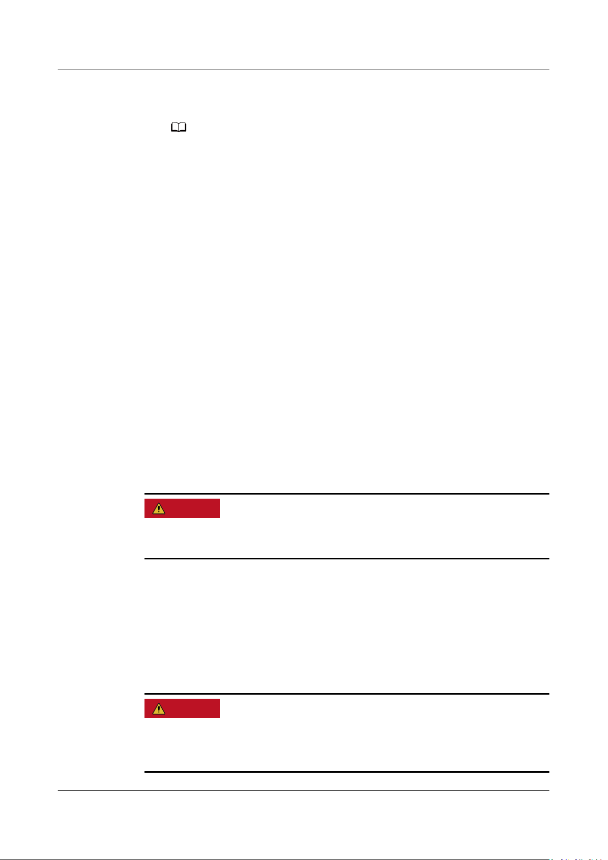
● Ensure that the ladder is securely positioned. The recommended angle for a
ladder against the
angle rule can be used to measure the angle.
berglass ladders when you need to perform live working at
rm.
oor is 75 degrees, as shown in the following gure. An
Issue 01 (2020-10-15) Copyright © Huawei Technologies Co., Ltd. 4
SUN2000-(20KTL, 29.9KTL, 30KTL, 36KTL, 40KTL)M3
User Manual 1 Safety Information
● When climbing a ladder, take the following precautions to reduce risks and
ensure safety:
– Keep your body steady.
– Do not climb higher than the fourth rung of the ladder from the top.
– Ensure that your body's center of gravity does not shift outside the legs
of the ladder.
Drilling Holes
When drilling holes into a wall or
● Wear goggles and protective gloves when drilling holes.
● When drilling holes, protect the equipment from shavings. After drilling, clean
up any shavings that have accumulated inside or outside the equipment.
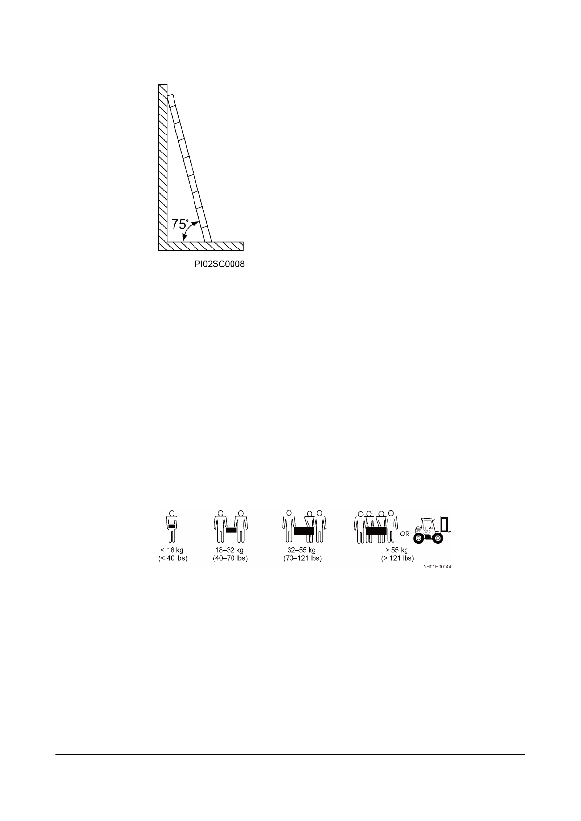
Moving Heavy Objects
● Be cautious to avoid injury when moving heavy objects.
● When moving the equipment by hand, wear protective gloves to prevent
injuries.
1.6 Commissioning
When the equipment is powered on for the
personnel set parameters correctly. Incorrect settings may result in inconsistency
with local
certication and aect the normal operation of the equipment.
oor, observe the following safety precautions:
rst time, ensure that professional
Issue 01 (2020-10-15) Copyright © Huawei Technologies Co., Ltd. 5

D ANGER
SUN2000-(20KTL, 29.9KTL, 30KTL, 36KTL, 40KTL)M3
User Manual 1 Safety Information
1.7 Maintenance and Replacement
High voltage generated by the equipment during operation may cause an electric
shock, which could result in death, serious injury, or serious property damage.
Prior to maintenance, power
precautions in this document and relevant documents.
● Maintain the equipment with sucient knowledge of this document and
using proper tools and testing equipment.
● Before maintaining the equipment, power it o and follow the instructions on
the delayed discharge label to ensure that the equipment is powered
● Place temporary warning signs or erect fences to prevent unauthorized access
to the maintenance site.
● If the equipment is faulty, contact your dealer.
● The equipment can be powered on only after all faults are
do so may escalate faults or damage the equipment.
o the equipment and strictly comply with the safety
o.
rectied. Failing to
Issue 01 (2020-10-15) Copyright © Huawei Technologies Co., Ltd. 6
NO TE
SUN2000-(20KTL, 29.9KTL, 30KTL, 36KTL, 40KTL)M3
User Manual 2 Overview
2 Overview
2.1 Overview
Function
Model
The SUN2000 inverter is a three-phase grid-tied PV string inverter that converts
the DC power generated by PV strings into AC power and feeds the power into the
power grid.
This document covers the following SUN2000 models:
● SUN2000-20KTL-M3
● SUN2000-29.9KTL-M3
● SUN2000-30KTL-M3
● SUN2000-36KTL-M3
● SUN2000-40KTL-M3
The SUN2000-20KTL-M3 supports 220 V (line voltage) power grids.
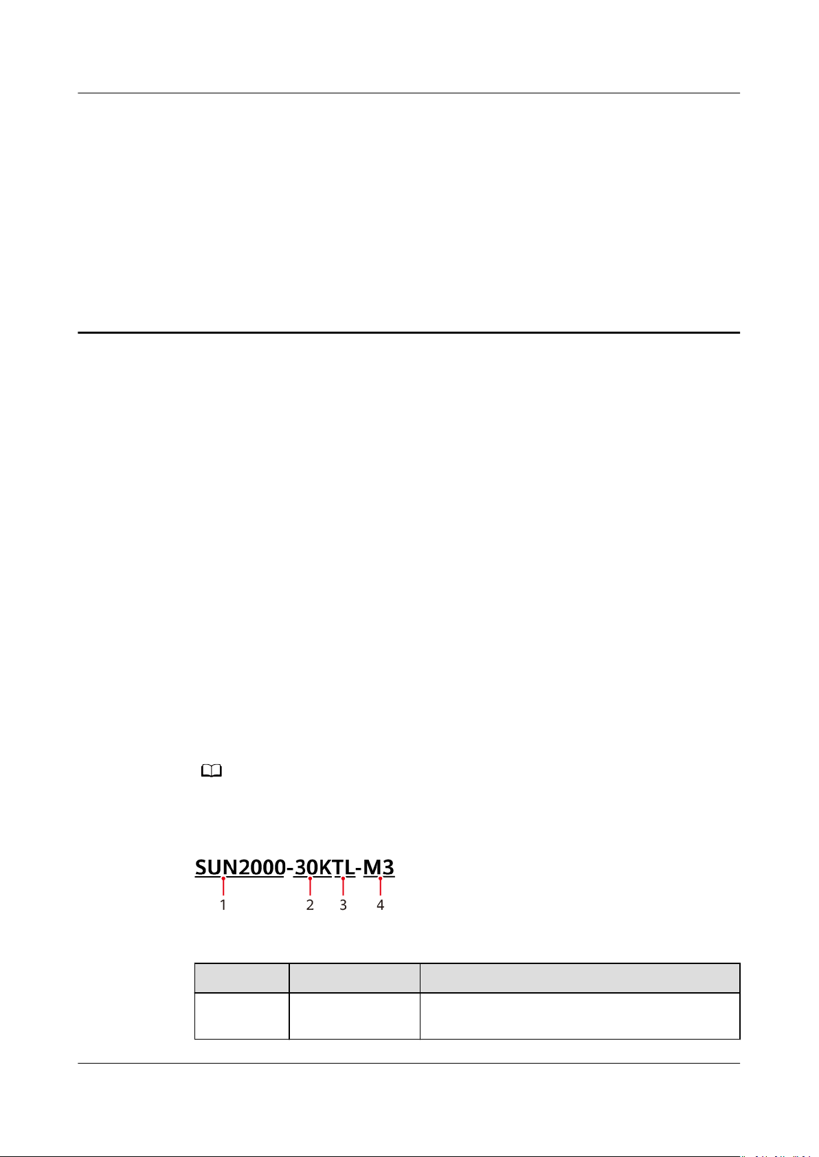
Figure 2-1 Model description (SUN2000-30KTL-M3 is used as an example)
Table 2-1 Model description
ID
1 Series name SUN2000: three-phase grid-tied PV string
Issue 01 (2020-10-15) Copyright © Huawei Technologies Co., Ltd. 7
Meaning Value
inverter
SUN2000-(20KTL, 29.9KTL, 30KTL, 36KTL, 40KTL)M3
User Manual 2 Overview
ID Meaning Value
2 Power class ● 20K: rated power of 20 kW
● 29.9K: rated power of 29.9 kW
● 30K: rated power of 30 kW
● 36K: rated power of 36 kW
● 40K: rated power of 40 kW
3 Topology TL: transformerless
4 Product code M3: product series with an input voltage level
of 1100 V DC
Networking Application
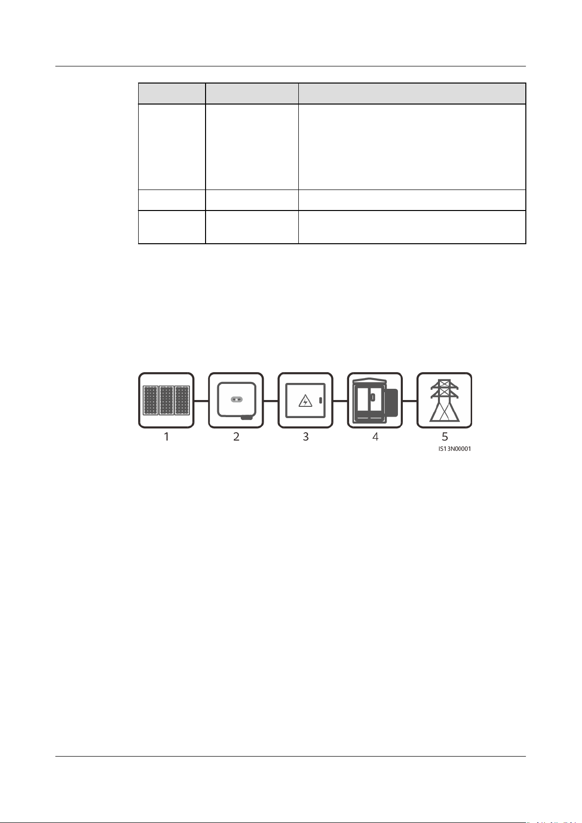
The SUN2000 applies to the grid-tied systems of industrial and commercial
rooftops and small ground PV plants. Typically, a grid-tied system consists of PV
strings, grid-tied inverters, AC switches, and power distribution units.
Figure 2-2 Networking application - single inverter scenario
(1) PV string
(4) Isolation transformer (5) Power grid
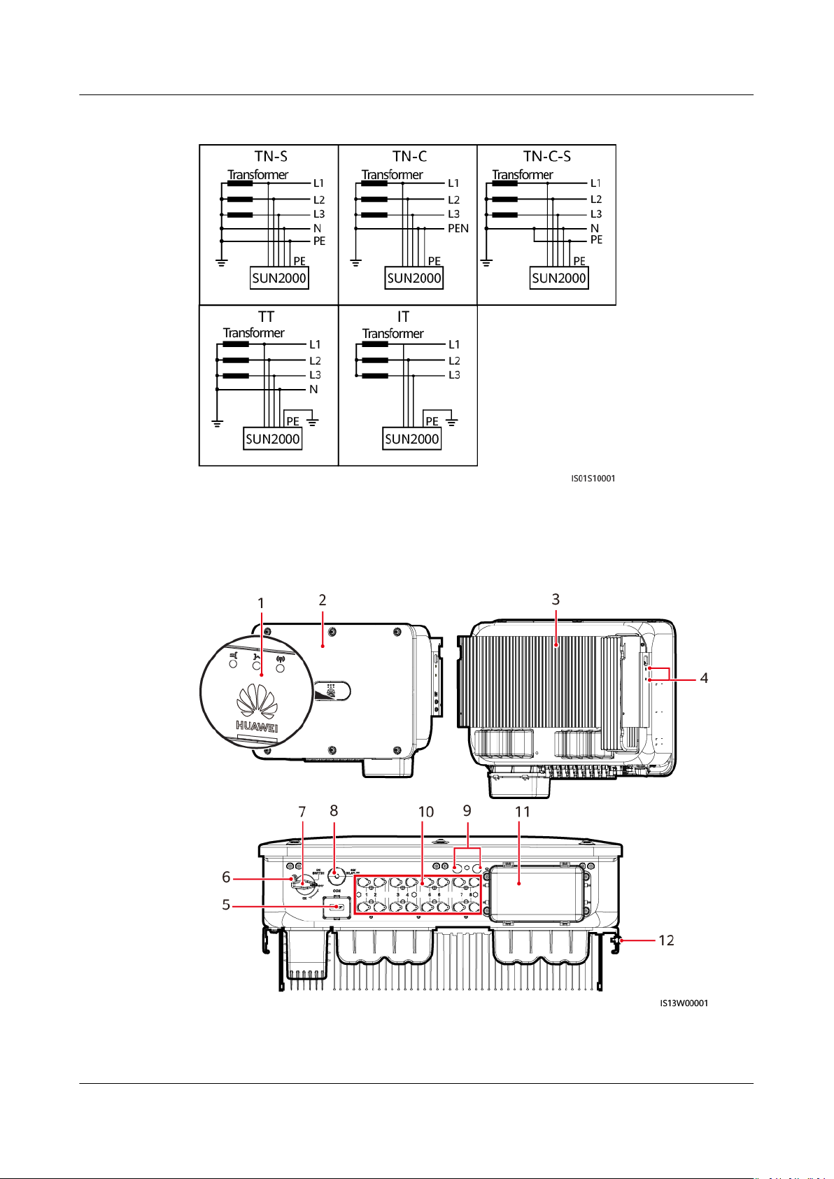
Supported Power Grid Types
The SUN2000 supports TN-S, TN-C, TN-C-S, TT, and IT power grids.
(2) SUN2000 (3) AC power distribution
unit
Issue 01 (2020-10-15) Copyright © Huawei Technologies Co., Ltd. 8
SUN2000-(20KTL, 29.9KTL, 30KTL, 36KTL, 40KTL)M3
User Manual 2 Overview
Figure 2-3 Power grid types
2.2 Appearance
Figure 2-4 Appearance
Issue 01 (2020-10-15) Copyright © Huawei Technologies Co., Ltd. 9
SUN2000-(20KTL, 29.9KTL, 30KTL, 36KTL, 40KTL)M3
User Manual 2 Overview
(1) LED indicator (2) Front panel
(3) Heat sink (4) Screws for xing the awning
(5) Communications port (COM) (6) Hole for the DC switch locking
screw
(7) DC switch (DC SWITCH) (8) Smart Dongle port (4G/WLAN-FE)
(9) Ventilation valve (10) DC input terminals (PV1–PV8)
(11) AC output port (12) Ground point
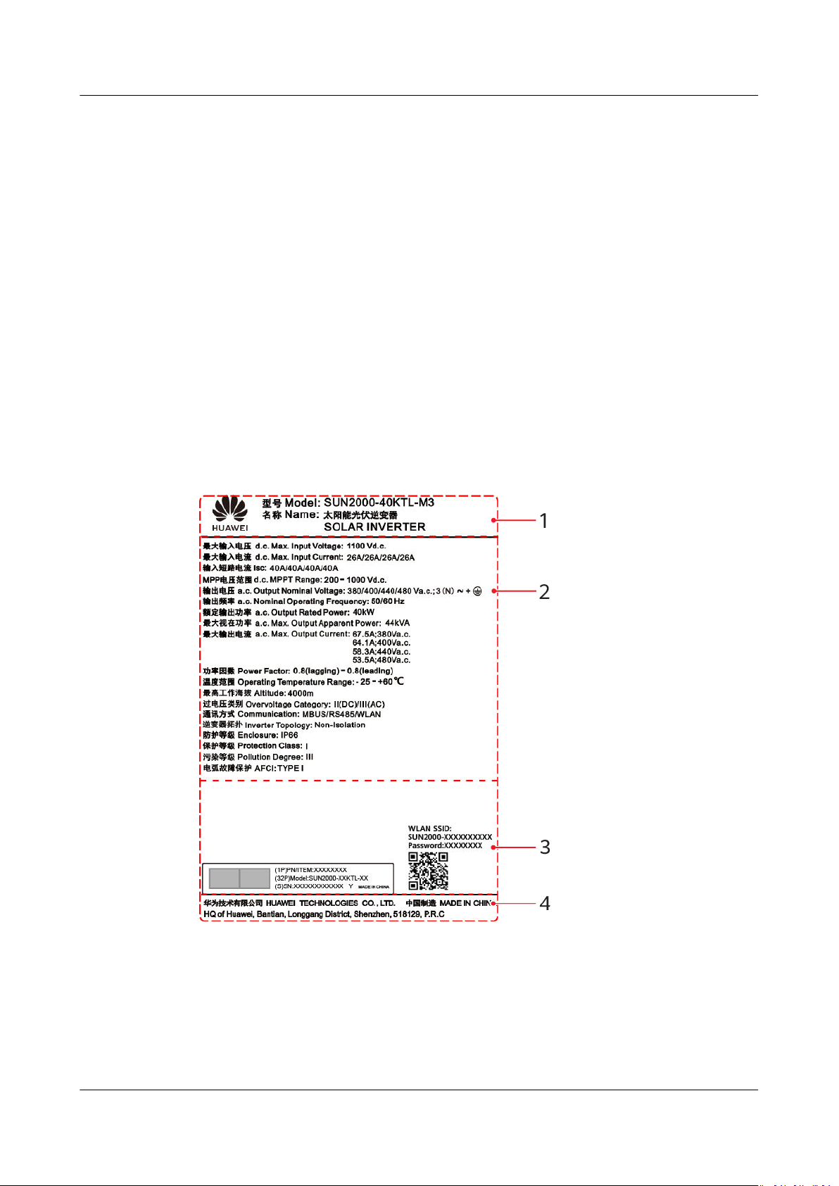
2.3 Label Description
Nameplate
Figure 2-5 Nameplate
(1) Trademark and product model (2) Key technical parameters
(3) Label information (4) Company name and country of
origin
Issue 01 (2020-10-15) Copyright © Huawei Technologies Co., Ltd. 10
NO TE
SUN2000-(20KTL, 29.9KTL, 30KTL, 36KTL, 40KTL)M3
User Manual 2 Overview
The nameplate gure is for reference only.
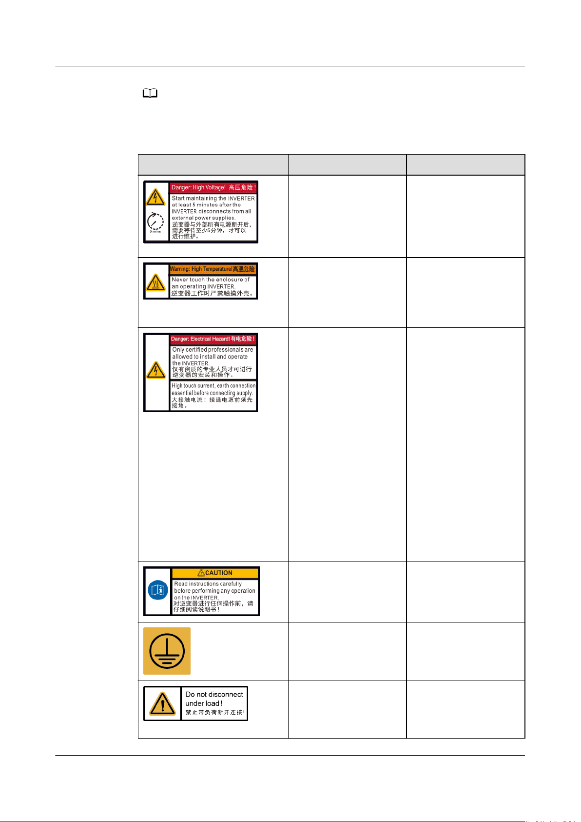
Enclosure Labels
Symbol Name Description
Delay discharge Residual voltage exists
after the SUN2000 is
powered o. It takes 5
minutes for the
SUN2000 to discharge
to the safe voltage.
Burn warning Do not touch a
running SUN2000
because it generates
high temperatures on
the shell.
Electric shock warning ● High voltage exists
after the SUN2000
is powered on. Only
qualied and
trained electrical
technicians are
allowed to perform
operations on the
SUN2000.
● High touch current
exists after the
SUN2000 is
powered on. Before
powering on the
SUN2000, ensure
that the SUN2000
is properly
grounded.
Refer to
documentation
Reminds operators to
refer to the documents
delivered with the
SUN2000.
Grounding label Indicates the position
for connecting the PE
cable.
Operation warning Do not remove the DC
input connector or AC
output connector with
power on.
Issue 01 (2020-10-15) Copyright © Huawei Technologies Co., Ltd. 11

SUN2000-(20KTL, 29.9KTL, 30KTL, 36KTL, 40KTL)M3
User Manual 2 Overview
Symbol Name Description
Weight label The SUN2000 is heavy
and needs to be
carried by three
persons.
Indicator Indicates the SUN2000
operating information.
2.4 Working Principles
2.4.1 Circuit Diagram
A SUN2000 can connect to a maximum of eight PV strings and has four MPPT
circuits inside. Each MPPT circuit tracks the maximum power point of two PV
strings. The SUN2000 converts DC power into single-phase AC power through an
inverter circuit. Surge protection is supported on both the DC and AC sides.
SUN2000 serial
number
SUN2000 WiFi login
QR code
Indicates the serial
number.
Scan the QR code to
connect to the Huawei
SUN2000 WiFi
network.
Issue 01 (2020-10-15) Copyright © Huawei Technologies Co., Ltd. 12

SUN2000-(20KTL, 29.9KTL, 30KTL, 36KTL, 40KTL)M3
User Manual 2 Overview
Figure 2-6 Schematic diagram
2.4.2 Working Modes
The SUN2000 can work in Standby, Operating, or Shutdown mode.
Figure 2-7 Working modes
Issue 01 (2020-10-15) Copyright © Huawei Technologies Co., Ltd. 13
SUN2000-(20KTL, 29.9KTL, 30KTL, 36KTL, 40KTL)M3
User Manual 2 Overview
Table 2-2 Working mode description
Working
Description
Mode
Standby The SUN2000 enters Standby mode when the external
environment does not meet the operating requirements. In
Standby mode:
● The SUN2000 continuously performs status check and enters
the Operating mode once the operating requirements are met.
● The SUN2000 enters Shutdown mode after detecting a
shutdown command or a fault after startup.
Operating In Operating mode:
● The SUN2000 converts DC power from PV strings into AC power
and feeds the power to the power grid.
● The SUN2000 tracks the maximum power point to maximize
the PV string output.
● If the SUN2000 detects a fault or a shutdown command, it
enters the Shutdown mode.
● The SUN2000 enters Standby mode after detecting that the PV
string output power is not suitable for connecting to the power
grid for generating power.
Shutdown ● In Standby or Operating mode, the SUN2000 enters Shutdown
mode after detecting a fault or shutdown command.
● In Shutdown mode, the SUN2000 enters Standby mode after
detecting a startup command or that the fault is rectied.
Issue 01 (2020-10-15) Copyright © Huawei Technologies Co., Ltd. 14

SUN2000-(20KTL, 29.9KTL, 30KTL, 36KTL, 40KTL)M3
User Manual 3 SUN2000 Storage
3 SUN2000 Storage
The following requirements should be met if the SUN2000 is not put into use
directly:
● Do not unpack the SUN2000.
● Keep the storage temperature at –40°C to +70°C and the humidity at 5%–
95% RH.
● Store the SUN2000 in a clean and dry place and protect it from dust and
water vapor corrosion.
● A maximum of six SUN2000s can be stacked. To avoid personal injury or
device damage, stack SUN2000s with caution to prevent them from falling
over.
● During the storage period, check the SUN2000 periodically (recommended:
every three months). If any rodent bites are found on the packing materials,
replace the packing materials immediately.
● If the SUN2000 has been stored for more than two years, it must be checked
and tested by professionals before being put into use.
Issue 01 (2020-10-15) Copyright © Huawei Technologies Co., Ltd. 15
NO TE
NO TE
SUN2000-(20KTL, 29.9KTL, 30KTL, 36KTL, 40KTL)M3
User Manual 4 Installation
4 Installation
4.1 Checking Before Installation
Outer Packing Materials
Before unpacking the inverter, check the outer packing materials for damage, such
as holes and cracks, and check the inverter model. If any damage is found or the
inverter model is not what you requested, do not unpack the package and contact
your supplier as soon as possible.
You are advised to remove the packing materials within 24 hours before installing the
inverter.
Package Contents
After unpacking the inverter, check that the contents are intact and complete. If
any damage is found or any component is missing, contact your supplier.
For details about the number of contents, see the
Packing List
in the packing case.
Issue 01 (2020-10-15) Copyright © Huawei Technologies Co., Ltd. 16
SUN2000-(20KTL, 29.9KTL, 30KTL, 36KTL, 40KTL)M3
User Manual 4 Installation
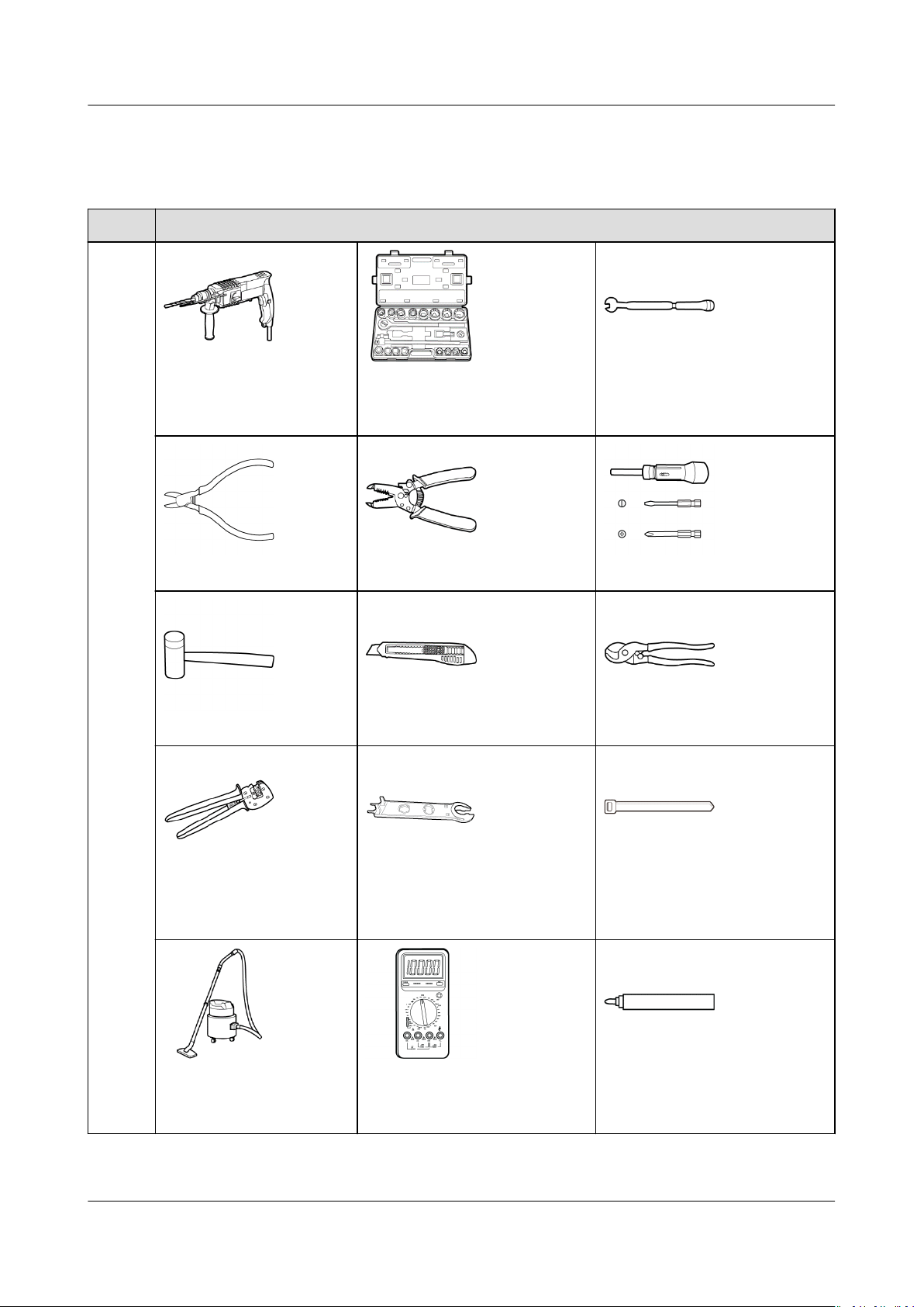
4.2 Tool Preparation
Type Tools and Instruments
Install
ation
Hammer drill (with a
Ф14 mm drill bit and a
Ф16 mm drill bit)
Diagonal pliers Wire stripper Torque screwdriver
Rubber mallet Utility knife Cable cutter
Torque socket and wrench Torque wrench
Crimping tool (model:
PV-CZM-22100)
Vacuum cleaner Multimeter (DC voltage
Issue 01 (2020-10-15) Copyright © Huawei Technologies Co., Ltd. 17
Open-end wrench (model:
PV-MS-HZ or PV-MS openend wrench)
measurement range ≥ 1100 V
DC)
Cable tie
Marker

SUN2000-(20KTL, 29.9KTL, 30KTL, 36KTL, 40KTL)M3
User Manual 4 Installation
Type Tools and Instruments
Steel measuring tape Level Hydraulic pliers
-
Heat shrink tubing Heat gun
Person
al
protec
tive
equip
ment
(PPE)
Safety gloves Safety goggles Anti-dust mask
- -
Safety boots
4.3 Selecting an Installation Position
Basic Requirements
● The SUN2000 is IP66-rated and can be installed indoors or outdoors.
● Do not install the SUN2000 in a place where a person can easily be exposed
to its enclosure and heat sinks, because these parts are extremely hot during
operation.
● Do not install the SUN2000 in areas with ammable or explosive materials.
● Do not install the SUN2000 in a place within children's reach.
● The SUN2000 will be corroded in salt areas, and the salt corrosion may cause
re. Do not install the SUN2000 outdoors in salt areas. A salt area refers to
the region within 500 m from the coast or prone to sea breeze. The eect
from sea breeze depends on weather conditions (such as typhoon and season
wind) or terrains (such as dams and hills).
Issue 01 (2020-10-15) Copyright © Huawei Technologies Co., Ltd. 18
SUN2000-(20KTL, 29.9KTL, 30KTL, 36KTL, 40KTL)M3
User Manual 4 Installation
Site Requirements
● The SUN2000 should be installed in a well-ventilated environment to ensure
good heat dissipation.
● If the SUN2000 is installed in a place exposed to direct sunlight, the power
may decrease as the temperature rises.
● You are advised to install the SUN2000 in a sheltered place or install an
awning over it.
Mounting Structure Requirements
● The mounting structure where the SUN2000 is installed must be
● Do not install the SUN2000 on ammable building materials.
● The SUN2000 is heavy. Ensure that the installation surface is solid enough to
bear the weight load.
● In residential areas, do not install the SUN2000 on drywalls or walls made of
similar materials which have a weak sound insulation performance because
the noise generated by the SUN2000 is noticeable.
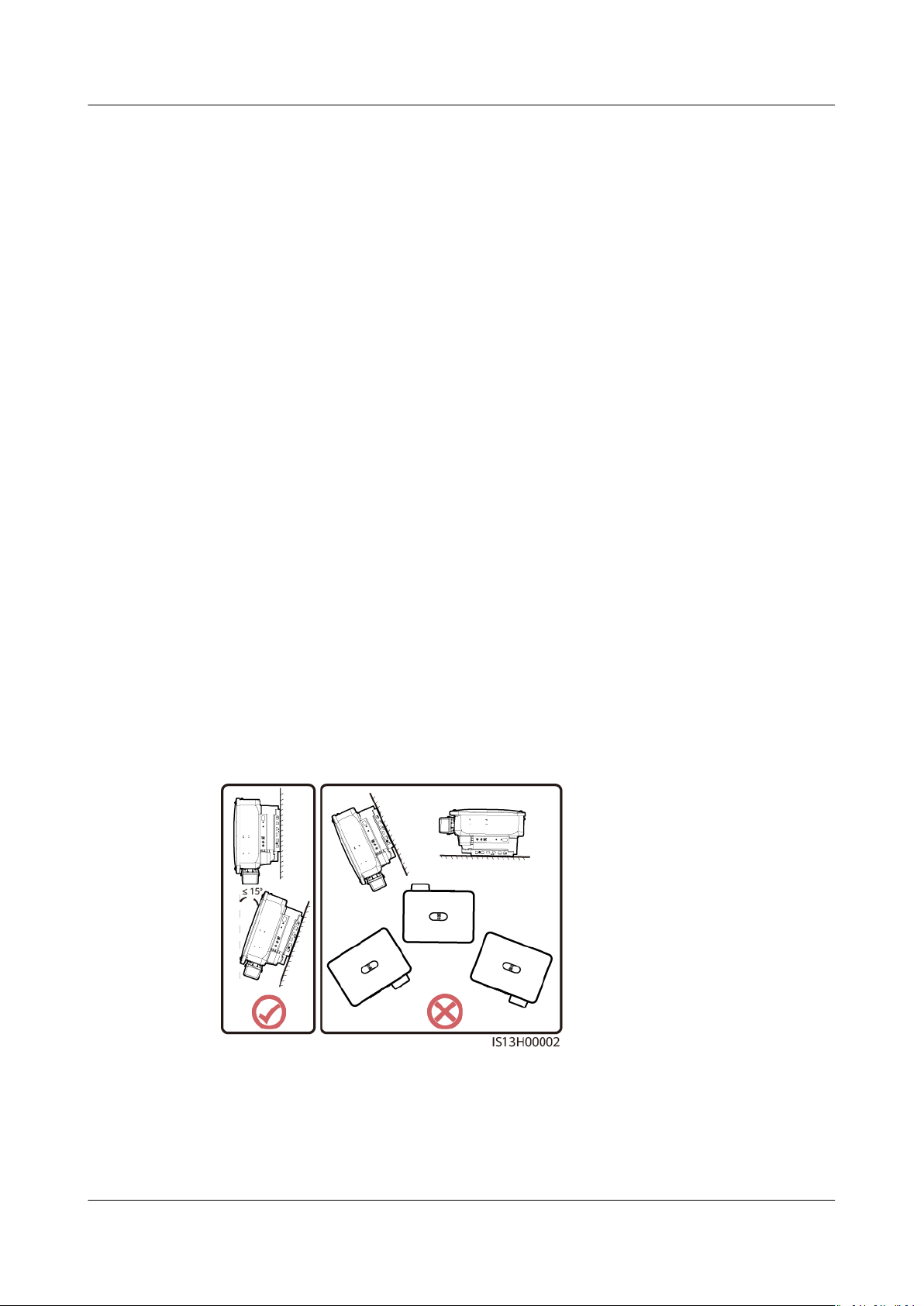
Installation Angle Requirements
The SUN2000 can be wall-mounted or support-mounted. Requirements for the
installation angle:
● Install the SUN2000 vertically or at a maximum back tilt of 15 degrees to
facilitate heat dissipation.
● Do not install the SUN2000 with a front tilt, excessive back tilt, side tilt,
horizontally, or upside down.
Figure 4-1 Installation angle
re resistant.
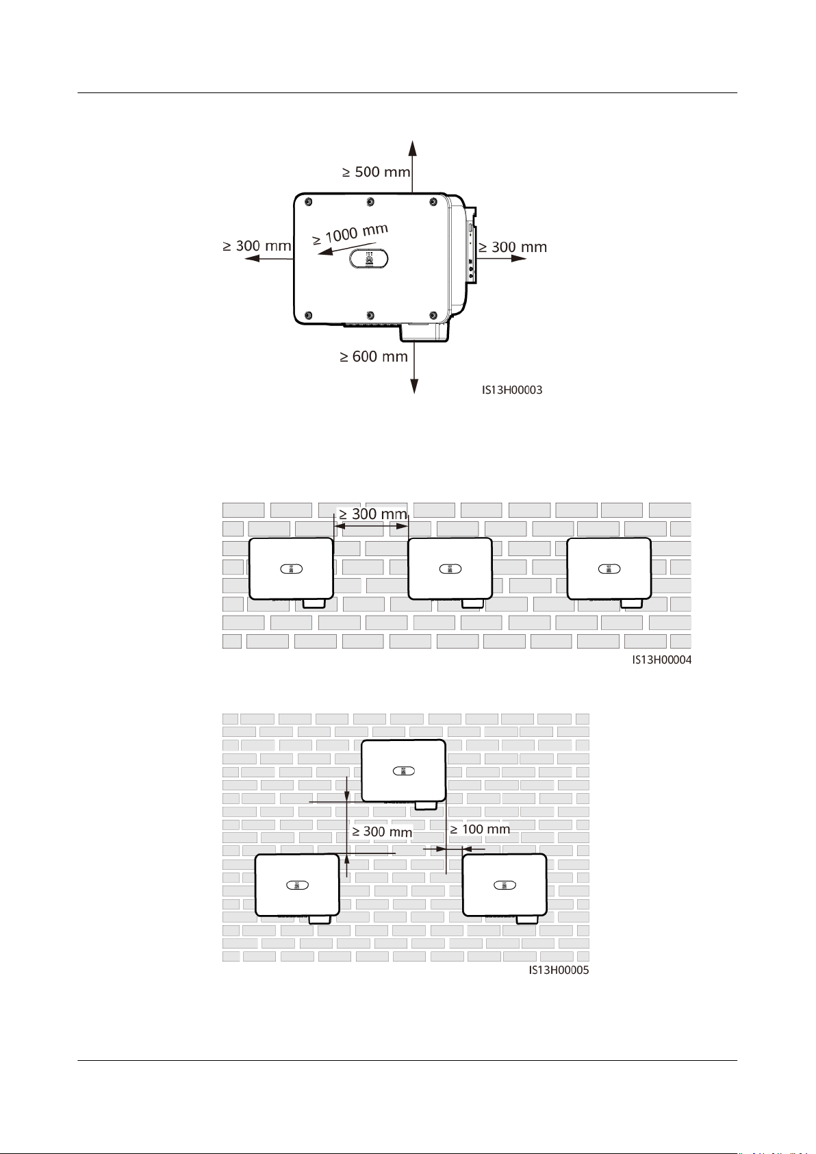
Installation Space Requirements
● Reserve enough clearance around the SUN2000 to ensure
installation and heat dissipation.
Issue 01 (2020-10-15) Copyright © Huawei Technologies Co., Ltd. 19
sucient space for
SUN2000-(20KTL, 29.9KTL, 30KTL, 36KTL, 40KTL)M3
User Manual 4 Installation
Figure 4-2 Installation space
● When installing multiple SUN2000s, install them in horizontal mode if ample
space is available and install them in triangle mode if no ample space is
available. Stacked installation is not recommended.
Figure 4-3 Horizontal installation (recommended)
Figure 4-4 Two-layer triangle installation (recommended)
Issue 01 (2020-10-15) Copyright © Huawei Technologies Co., Ltd. 20

NO TE
SUN2000-(20KTL, 29.9KTL, 30KTL, 36KTL, 40KTL)M3
User Manual 4 Installation
Figure 4-5 Three-layer triangle installation (not recommended)
Figure 4-6 Stacked installation (not recommended)
The installation diagrams are for reference only and are irrelevant to the SUN2000
cascading scenario.
4.4 Moving the SUN2000
Procedure
Step 1 Lift the SUN2000 from the packing case and move it to the specied installation
position.
Issue 01 (2020-10-15) Copyright © Huawei Technologies Co., Ltd. 21
CA UTION
SUN2000-(20KTL, 29.9KTL, 30KTL, 36KTL, 40KTL)M3
User Manual 4 Installation
● Move the SUN2000 with care to prevent device damage and personal injury.
● Do not use the wiring terminals and ports at the bottom to support any weight
of the SUN2000.
● Place a foam pad or cardboard under the SUN2000 to protect the SUN2000
enclosure from damage.
Figure 4-7 Moving the SUN2000
----End
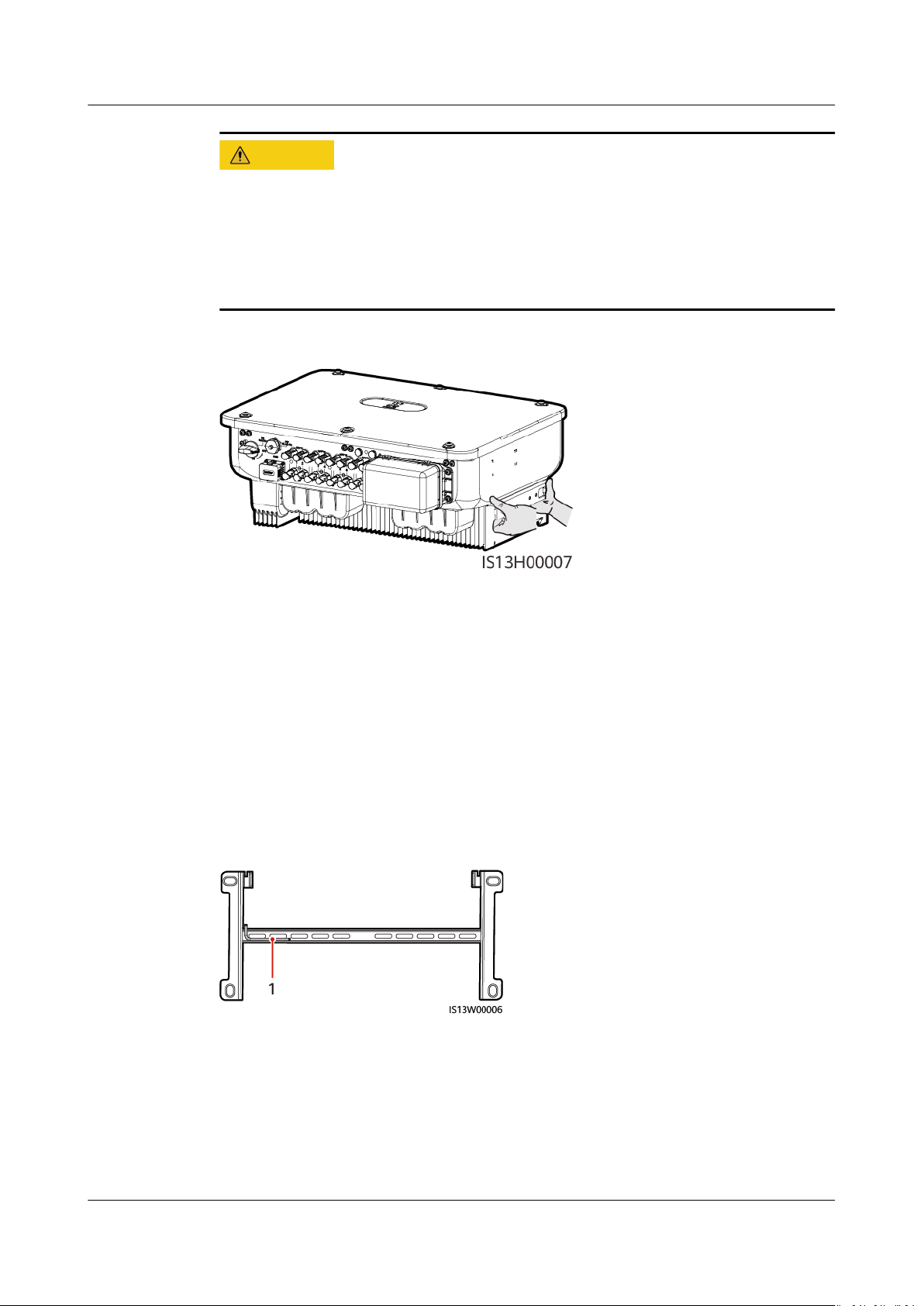
4.5 Installing the Mounting Bracket
Installation Precautions
Before installing the mounting bracket, remove the security Torx wrench and set it
aside.
Figure 4-8 Position for binding the security Torx wrench
(1) Security Torx wrench
Issue 01 (2020-10-15) Copyright © Huawei Technologies Co., Ltd. 22
Figure 4-9 shows the dimensions of the mounting holes for the SUN2000.

NO TE
SUN2000-(20KTL, 29.9KTL, 30KTL, 36KTL, 40KTL)M3
User Manual 4 Installation
Figure 4-9 Mounting bracket dimensions
4.5.1 Support-mounted Installation
Procedure
Step 1 Secure the mounting bracket.
Figure 4-10 Securing the mounting bracket
You are advised to apply anti-rust paint on the hole positions for protection.
----End
Issue 01 (2020-10-15) Copyright © Huawei Technologies Co., Ltd. 23
 Loading...