

Page 1
SUN2000-(2KTL-5KTL)-L0
User Manual
Issue
01
Date
2018-08-30
HUAWEI TECHNOLOGIES CO., LTD.
Page 2

Issue 01 (2018-08-30)
Copyright © Huawei Technologies Co., Ltd.
i
Copyright © Huawei Technologies Co., Ltd. 2018. All rights reserved.
No part of this document may be reproduced or transmitted in any form or by any means without prior
written consent of Huawei Technologies Co., Ltd.
Trademarks and Permissions
and other Huawei trademarks are trademarks of Huawei Technologies Co., Ltd.
All other trademarks and trade names mentioned in this document are the property of their respective
holders.
Notice
The purchased products, services and features are stipulated by the contract made between Huawei and
the customer. All or part of the products, services and features described in this document may not be
within the purchase scope or the usage scope. Unless otherwise specified in the contract, all statements,
information, and recommendations in this document are provided "AS IS" without warranties, guarantees or
representations of any kind, either express or implied.
The information in this document is subject to change without notice. Every effort has been made in the
preparation of this document to ensure accuracy of the contents, but all statements, information, and
recommendations in this document do not constitute a warranty of any kind, express or implied.
Huawei Technologies Co., Ltd.
Address:
Huawei Industrial Base
Bantian, Longgang
Shenzhen 518129
People's Republic of China
Website:
http://e.huawei.com
Page 3
SUN2000-(2KTL-5KTL)-L0
User Manual
About This Document
Issue 01 (2018-08-30)
Copyright © Huawei Technologies Co., Ltd.
ii
Purpose
Symbol
Description
Indicates an imminently hazardous situation which, if not
avoided, will result in serious injury or death.
Indicates a potentially hazardous situation which, if not
avoided, could result in serious injury or death.
Indicates a potentially hazardous situation which, if not
avoided, may result in minor or moderate injury.
Indicates a potentially hazardous situation which, if not
avoided, could result in equipment damage, data loss,
performance deterioration, or unanticipated results.
NOTICE is used to address practices not related to personal
injury.
This document describes the SUN2000-(2KTL-5KTL) -L0 in terms of its installation,
electrical connections, commissioning, maintenance, and troubleshooting.
SUN2000-(2KTL-5KTL)-L0 is abbreviated as SUN2000. Before installing and operating the
SUN2000, ensure that you are familiar with the features, functions, and safety precautions
provided in this document.
Intended Audience
About This Document
This document is intended for:
Installers
Users
Symbol Conventions
The symbols that may be found in this document are defined as follows.
Page 4
SUN2000-(2KTL-5KTL)-L0
User Manual
About This Document
Issue 01 (2018-08-30)
Copyright © Huawei Technologies Co., Ltd.
iii
Symbol
Description
Calls attention to important information, best practices and
tips.
NOTE is used to address information not related to personal
injury, equipment damage, or environment deterioration.
Change History
Changes between document issues are cumulative. The latest document issue contains all
updates made in previous issues.
Issue 01 (2018-08-30)
This issue is used for first office application (FOA).
Page 5

SUN2000-(2KTL-5KTL)-L0
User Manual
Contents
Issue 01 (2018-08-30)
Copyright © Huawei Technologies Co., Ltd.
iv
Contents
About This Document .................................................................................................................... ii
1 Safety Precautions ......................................................................................................................... 1
2 Product Overview ......................................................................................................................... 5
2.1 Product Introduction ..................................................................................................................................................... 5
2.2 Appearance ................................................................................................................................................................... 7
2.3 Label Descriptions ...................................................................................................................................................... 12
2.4 Working Principles...................................................................................................................................................... 15
3 Storage ........................................................................................................................................... 17
4 System Installation ..................................................................................................................... 18
4.1 Checking Before Installation ...................................................................................................................................... 18
4.2 Tools and Instruments ................................................................................................................................................. 19
4.3 Determining the Installation Position ......................................................................................................................... 20
4.4 Installing the Mounting Bracket ................................................................................................................................. 24
4.4.1 Wall-Mounted Installation ....................................................................................................................................... 25
4.4.2 Support-mounted Installation .................................................................................................................................. 27
4.5 Installing the SUN2000 .............................................................................................................................................. 29
4.6 (Optional) Installing the WiFi Antenna ....................................................................................................................... 33
4.7 (Optional) Installing the 4G Module ........................................................................................................................... 34
5 Electrical Connections ................................................................................................................ 36
5.1 Preparing Cables ......................................................................................................................................................... 37
5.2 Installing the PE Cable ............................................................................................................................................... 39
5.3 Installing the AC Output Power Cable ........................................................................................................................ 41
5.4 Installing the DC Input Power Cable .......................................................................................................................... 45
5.5 Installing the Signal Cable .......................................................................................................................................... 51
6 System Commissioning ............................................................................................................. 55
6.1 Checking Before Power-On ........................................................................................................................................ 55
6.2 Powering On the System............................................................................................................................................. 56
6.3 Powering Off the System ............................................................................................................................................ 57
7 System Maintenance................................................................................................................... 59
7.1 Routine Maintenance ................................................................................................ ................................ .................. 59
Page 6

SUN2000-(2KTL-5KTL)-L0
User Manual
Contents
Issue 01 (2018-08-30)
Copyright © Huawei Technologies Co., Ltd.
v
7.2 Troubleshooting .......................................................................................................................................................... 60
8 Handling the SUN2000 .............................................................................................................. 66
8.1 Removing the SUN2000 ............................................................................................................................................. 66
8.2 Packing the SUN2000 ................................................................................................................................................. 66
8.3 Disposing of the SUN2000 ................................................................................................................................ ......... 66
9 Technical Specifications ............................................................................................................ 67
A Grid Codes................................................................................................................................... 70
B Acronyms and Abbreviations .................................................................................................. 71
Page 7

SUN2000-(2KTL-5KTL)-L0
User Manual
1 Safety Precautions
Issue 01 (2018-08-30)
Copyright © Huawei Technologies Co., Ltd.
1
General Safety
1 Safety Precautions
Before performing operations, read through this manual and follow all the precautions to
prevent accidents. The "DANGER," "WARNING," "CAUTION," and "NOTICE"
statements in this document do not represent all the safety instructions. They are only
supplements to the safety instructions.
Only certified electricians are allowed to install, connect cables for, commission, maintain,
and troubleshoot Huawei products, and they must understand basic safety precautions to
avoid hazards.
Disclaimer
When operating Huawei equipment, in addition to following the general precautions in this
document, follow the specific safety instructions given by Huawei. Huawei will not be liable
for any consequence caused by the violation of the safety operation regulations and design,
production, and usage standards.
Huawei shall not be liable for any consequence caused by any of the following events:
Damage caused by transportation
Storage conditions that do not meet the requirements specified in this document
Incorrect storage, installation, or use
Installation or use by unqualified personnel
Failure to comply with the operation instructions and safety precautions in this document
Operation in extreme environments which are not covered in this document
Operation beyond specified ranges
Unauthorized modifications to the product or software code or removal of the product
Device damage due to force majeure (such as lightning, earthquakes, fire, and storms)
Warranty expiration without extension of the warranty service
Installation or use in environments which are not specified in related international
standards
Page 8
SUN2000-(2KTL-5KTL)-L0
User Manual
1 Safety Precautions
Issue 01 (2018-08-30)
Copyright © Huawei Technologies Co., Ltd.
2
Personnel Requirements
Only certified electricians are allowed to install, connect cables for, commission, maintain,
troubleshoot, and replace the SUN2000. They should:
Receive professional training.
Read through this document and follow all the precautions.
Be familiar with the safety specifications about the electrical system.
Understand the composition and working principles of the grid-tied PV system and local
regulations.
Wear proper personal protective equipment (PPE).
Protecting Labels
Do not scrawl or damage any labels on the SUN2000 enclosure because these labels
contain important information about safe operation.
Do not scrawl or damage the nameplate on the SUN2000 enclosure. This nameplate
contains important product information.
Installation
Never power on the SUN2000 during installation.
Ensure that the SUN2000 is not connected to a power supply or powered on before
installation is complete.
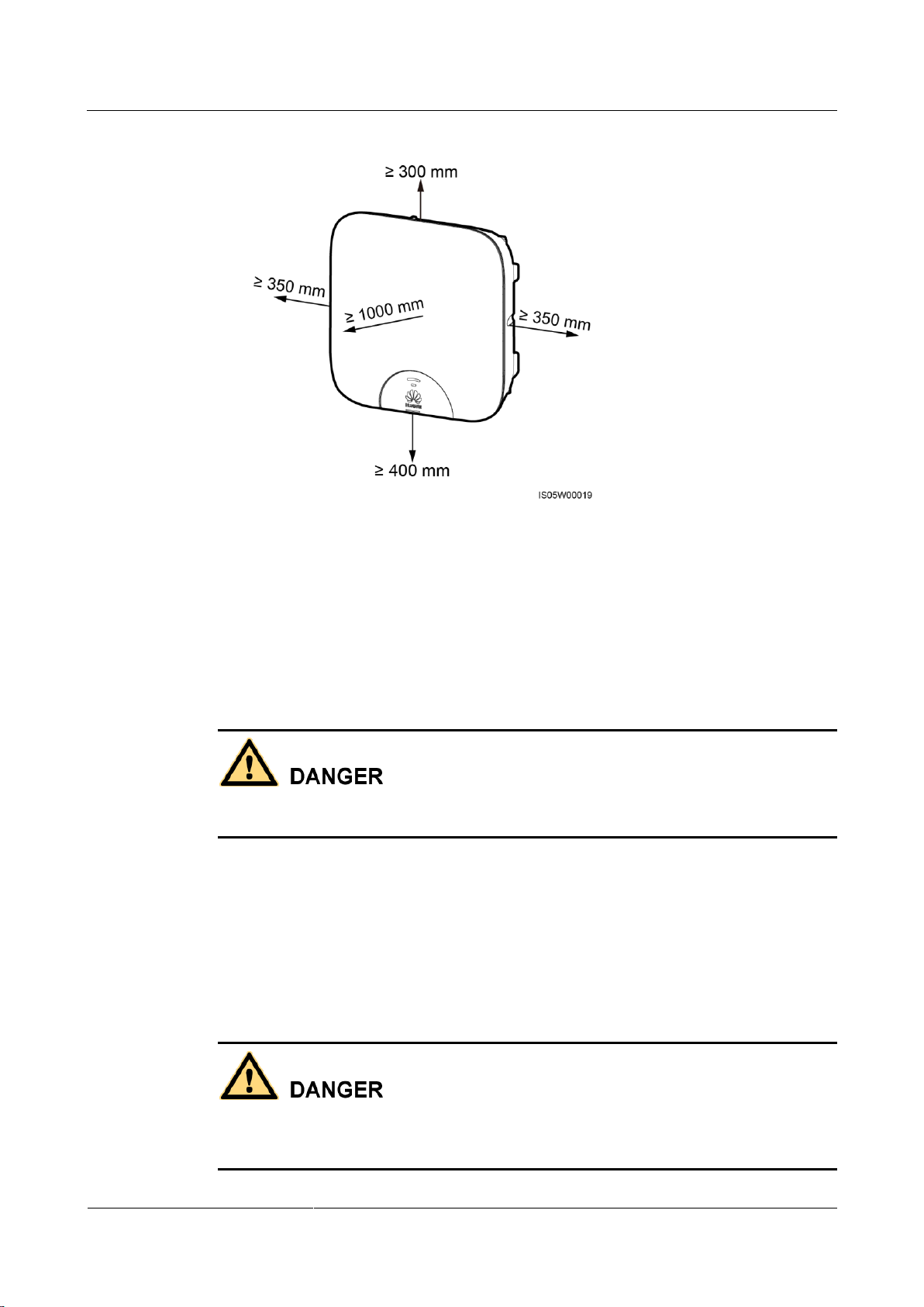
To allow proper heat dissipation and installation, maintain appropriate clearances
between the SUN2000 and other objects, as shown in Figure 1-1. If you have any
questions about the clearances, consult technical support engineers.
Page 9
SUN2000-(2KTL-5KTL)-L0
User Manual
1 Safety Precautions
Issue 01 (2018-08-30)
Copyright © Huawei Technologies Co., Ltd.
3
Figure 1-1 Installation clearances
Ensure that the SUN2000 is installed in a well-ventilated environment.
Ensure that the SUN2000 heat sinks are free from blockage.
Do not open the front panel of the SUN2000.
Do not remove the terminals and ports at the bottom of the SUN2000.
Electrical Connections
Before connecting cables, ensure that the SUN2000 is secured in position and not damaged in
any way. Otherwise, electric shocks or fire may occur.
Ensure that all electrical connections comply with the local electrical standards.
Obtain approval from the local utility company before using the SUN2000 to generate
electricity in grid-tied mode.
Ensure that the cables used in a grid-tied PV system are properly connected and insulated
and meet all specification requirements.
Operation
The high voltage generated by the SUN2000 during operation may cause an electric shock,
which can result in serious property damage, serious injury, or death. Strictly comply with the
safety precautions in this document and associated documents when operating the SUN2000.
Page 10
SUN2000-(2KTL-5KTL)-L0
User Manual
1 Safety Precautions
Issue 01 (2018-08-30)
Copyright © Huawei Technologies Co., Ltd.
4
When the SUN2000 is powered on for the first time, only certified electricians are
allowed to perform quick setting. Incorrect settings may affect the normal SUN2000
operation and cause the SUN2000 to not comply with the country certification.
When the SUN2000 is operating, do not disconnect under load.
Do not touch an energized SUN2000 because the heat sink reaches a high temperature.
Follow local laws and regulations when operating the equipment.
Maintenance and Replacement
The high voltage generated by the SUN2000 during operation may cause an electric shock,
which can result in serious property damage, serious injury, or death. Prior to maintenance,
power off the SUN2000 and strictly comply with the safety precautions in this document and
associated documents to operate the SUN2000.
Before performing maintenance on the SUN2000, ensure that you have sufficient
knowledge of this document, and proper tools and testing equipment.
Before performing maintenance tasks, power off the SUN2000 and wait at least 5
minutes.
Temporary warning signs or fences must be placed to prevent unauthorized people from
entering the site.
If the SUN2000 is faulty, contact your supplier.
The SUN2000 can be powered on only after all faults are rectified. Failing to do so may
escalate faults or damage the device.
Observe ESD precautions and wear ESD gloves during maintenance.
Page 11
SUN2000-(2KTL-5KTL)-L0
User Manual
2 Product Overview
Issue 01 (2018-08-30)
Copyright © Huawei Technologies Co., Ltd.
5
2.1 Product Introduction
No.
Meaning
Description
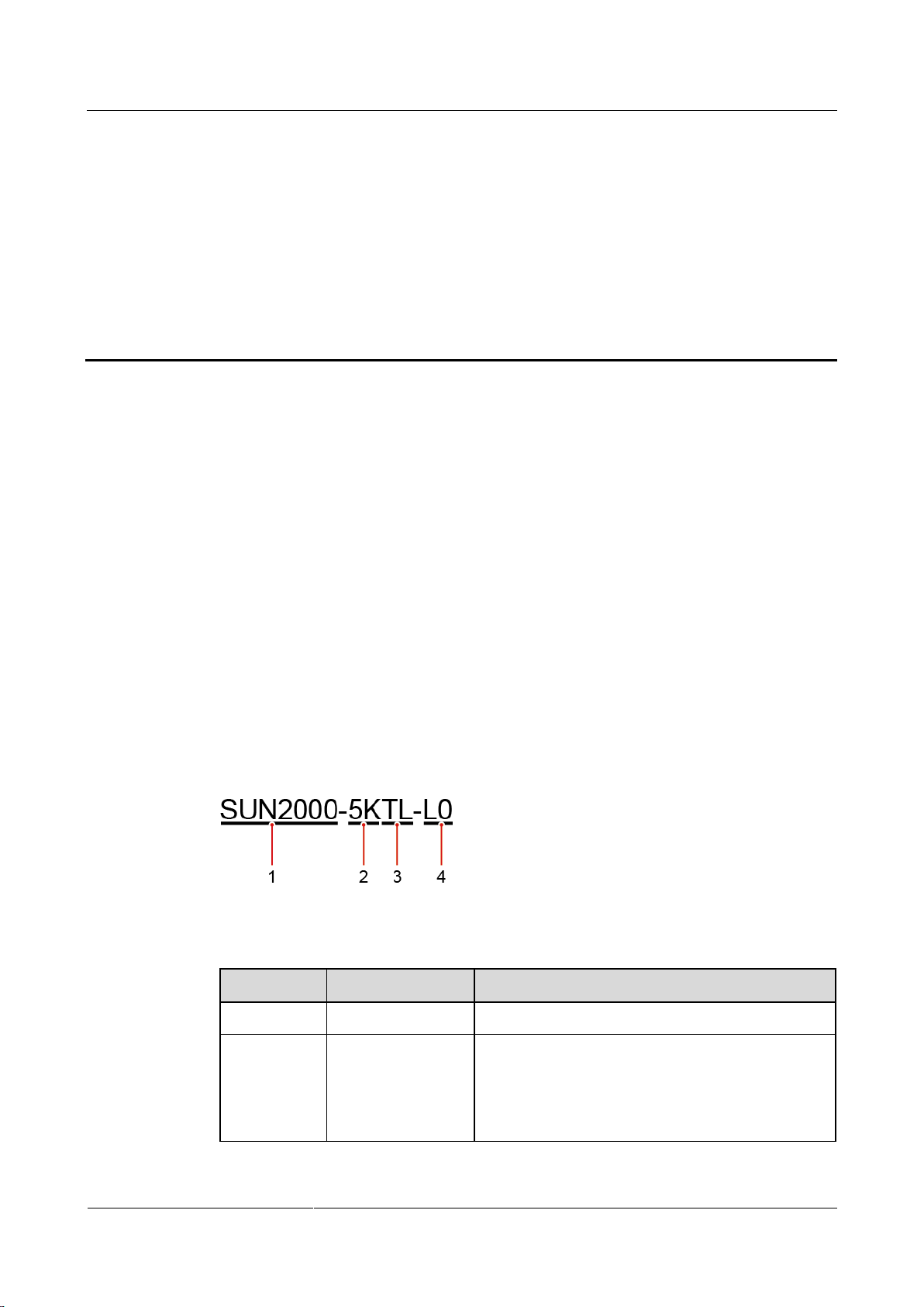
1
Series name
SUN2000: single-phase grid-tied PV string inverter
2
Power level
2K: The power level is 2K.
3K: The power level is 3K.
4K: The power level is 4K.
5K: The power level is 5K.
Function
The SUN2000 is a single-phase grid-tied PV string inverter that converts the DC power
generated by PV strings into AC power and feeds the electricity into the power grid.
2 Product Overview
Models
This document involves the following product models:
SUN2000-2KTL-L0
SUN2000-3KTL-L0
SUN2000-4KTL-L0
SUN2000-5KTL-L0
Figure 2-1 Designation explanation of the SUN2000-5KTL-L0
Table 2-1 Designation explanation
Page 12
SUN2000-(2KTL-5KTL)-L0
User Manual
2 Product Overview
Issue 01 (2018-08-30)
Copyright © Huawei Technologies Co., Ltd.
6
No.
Meaning
Description
3
Topology
TL: transformerless
4
Design code
L0: residential
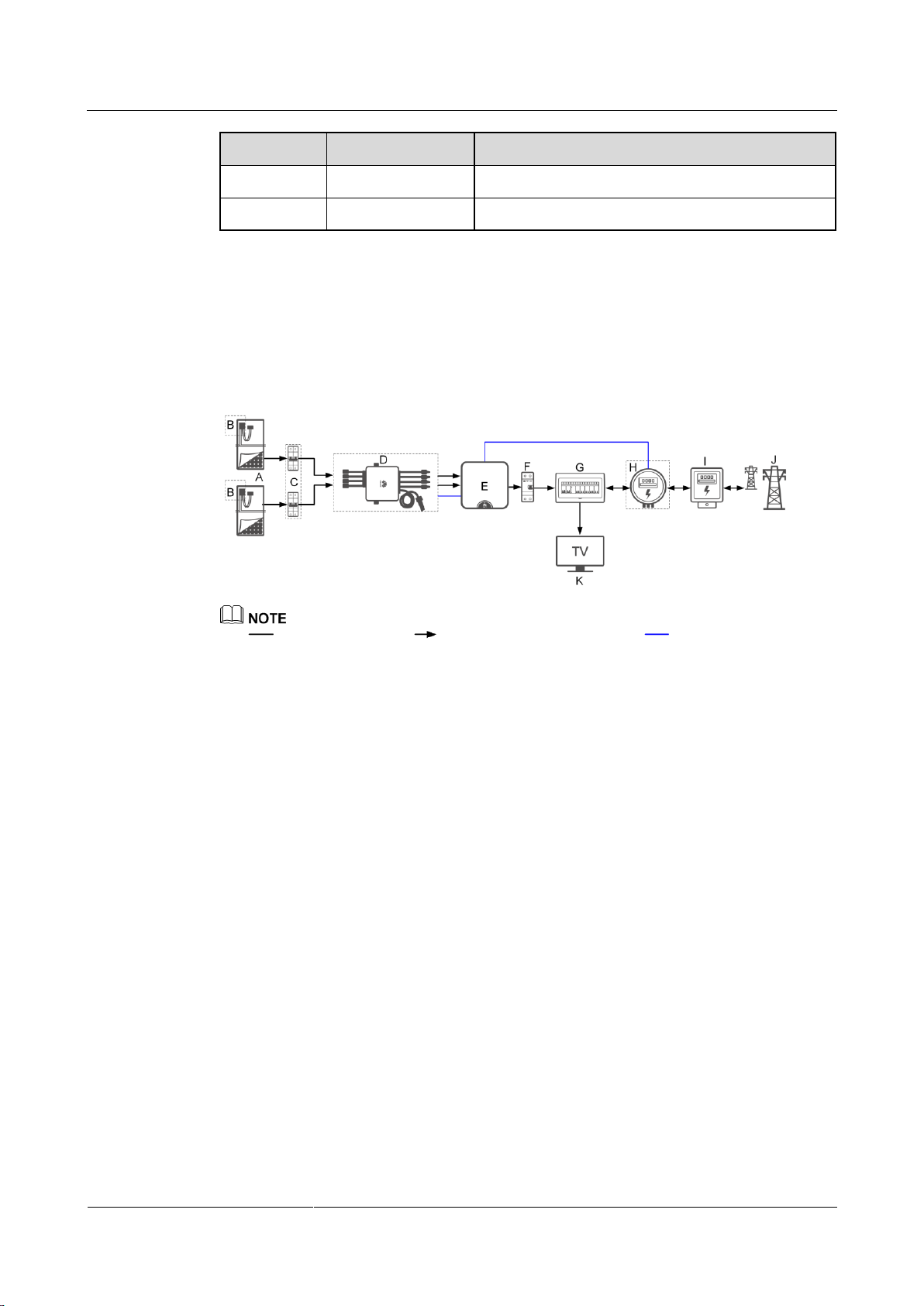
(A) PV string
(B) Smart PV Optimizer
(C) DC switch
(D) Smart PV Safety Box
(E) SUN2000
(F) AC switch
(G) Power distribution unit
(H) Smart Power Sensor
(I) Power meter
(J) Power grid
(K) Home load
Networking Application
The SUN2000 applies to a residential rooftop grid-tied system. Typically, a grid-tied system
consists of the PV string, grid-tied inverter, AC switch, and power distribution unit.
Figure 2-2 Network diagram (dashed boxes indicate optional components)
indicates a power cable, indicates the power flow direction, indicates a signal cable.
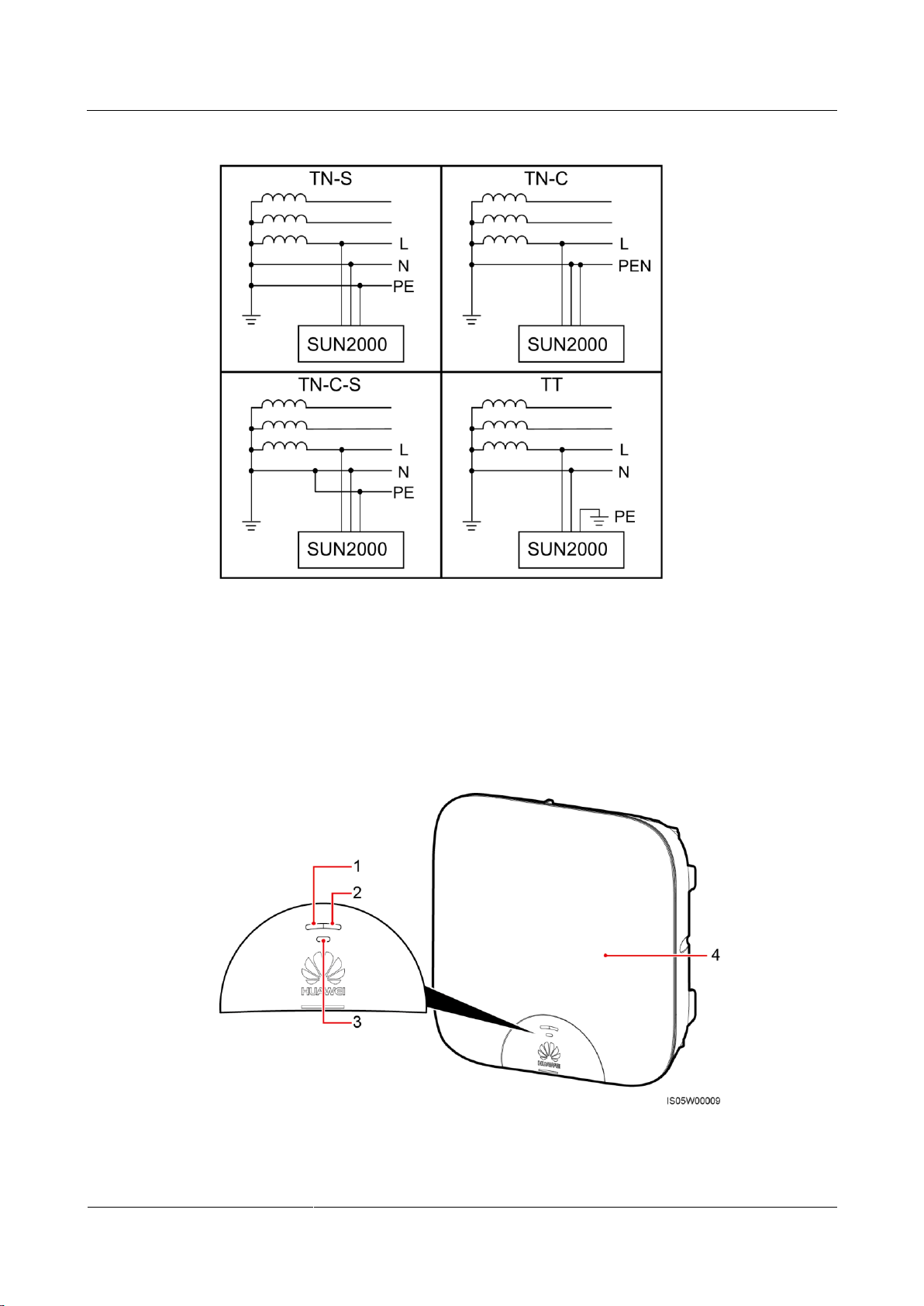
Supported Power Grid
The power grids supported by the SUN2000 include TN-S, TN-C, TN-C-S, and TT. In a TT
power grid, the N-PE voltage should be lower than 30 V.
Page 13
SUN2000-(2KTL-5KTL)-L0
User Manual
2 Product Overview
Issue 01 (2018-08-30)
Copyright © Huawei Technologies Co., Ltd.
7
Figure 2-3 Power grid types
(1) LED 1
(2) LED 2
(3) LED 3
(4) Front panel
2.2 Appearance
Front View
Figure 2-4 Front view
Page 14
SUN2000-(2KTL-5KTL)-L0
User Manual
2 Product Overview
Issue 01 (2018-08-30)
Copyright © Huawei Technologies Co., Ltd.
8
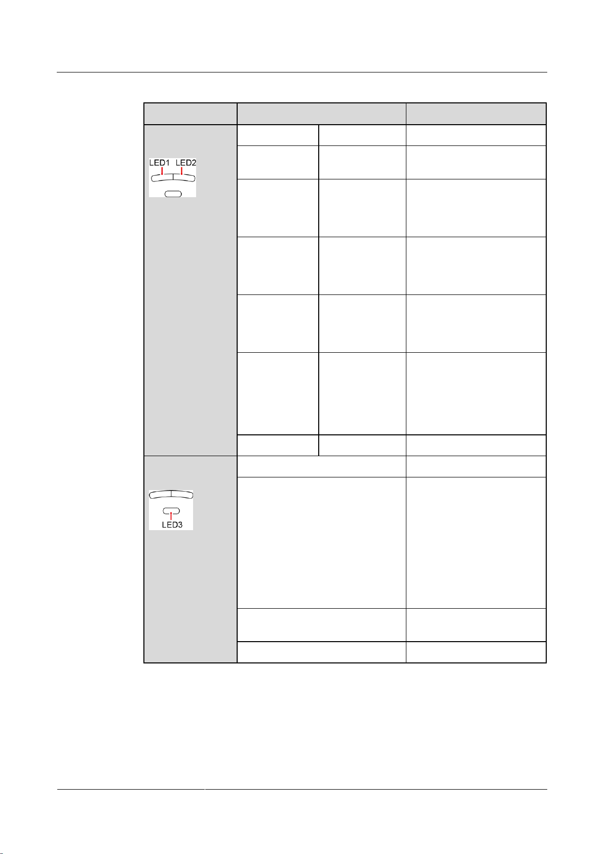
Table 2-2 LED description
Type
Status
Meaning
Running
indication
LED 1
LED 2
N/A
Steady green
Steady green
The SUN2000 is exporting
power to the power grid.
Blinking green
at long intervals
(on for 1s and
then off for 1s)
Off
The DC is on and the AC is
off.
Off
Blinking green at
long intervals (on
for 1s and then
off for 1s)
The DC is off and the AC is
on.
Blinking green
at long intervals
(on for 1s and
then off for 1s)
Blinking green at
long intervals (on
for 1s and then
off for 1s)
Both the DC and AC are on,
and the SUN2000 is not
exporting power to the power
grid.
Off
Off
Both the DC and AC are off,
or the SUN2000 is in low
power consumption mode
which means that the
monitoring system of the
SUN2000 hibernates.
Steady red
Steady red
The SUN2000 is faulty
Communication
indication
LED 3
N/A
Blinking green at short intervals (on
for 0.2s and then off for 0.2s)
Communicating
(Communicating refers to that
the communication with the
upper-level management unit
is in progress. However, if a
mobile phone accesses the
SUN2000, the LED indicates
the "mobile phone access
status: blinking green at long
intervals" first.)
Blinking green at long intervals (on
for 1s and then off for 1s)
The mobile phone has
connected to the SUN2000.
Off
No communication
Page 15
SUN2000-(2KTL-5KTL)-L0
User Manual
2 Product Overview
Issue 01 (2018-08-30)
Copyright © Huawei Technologies Co., Ltd.
9
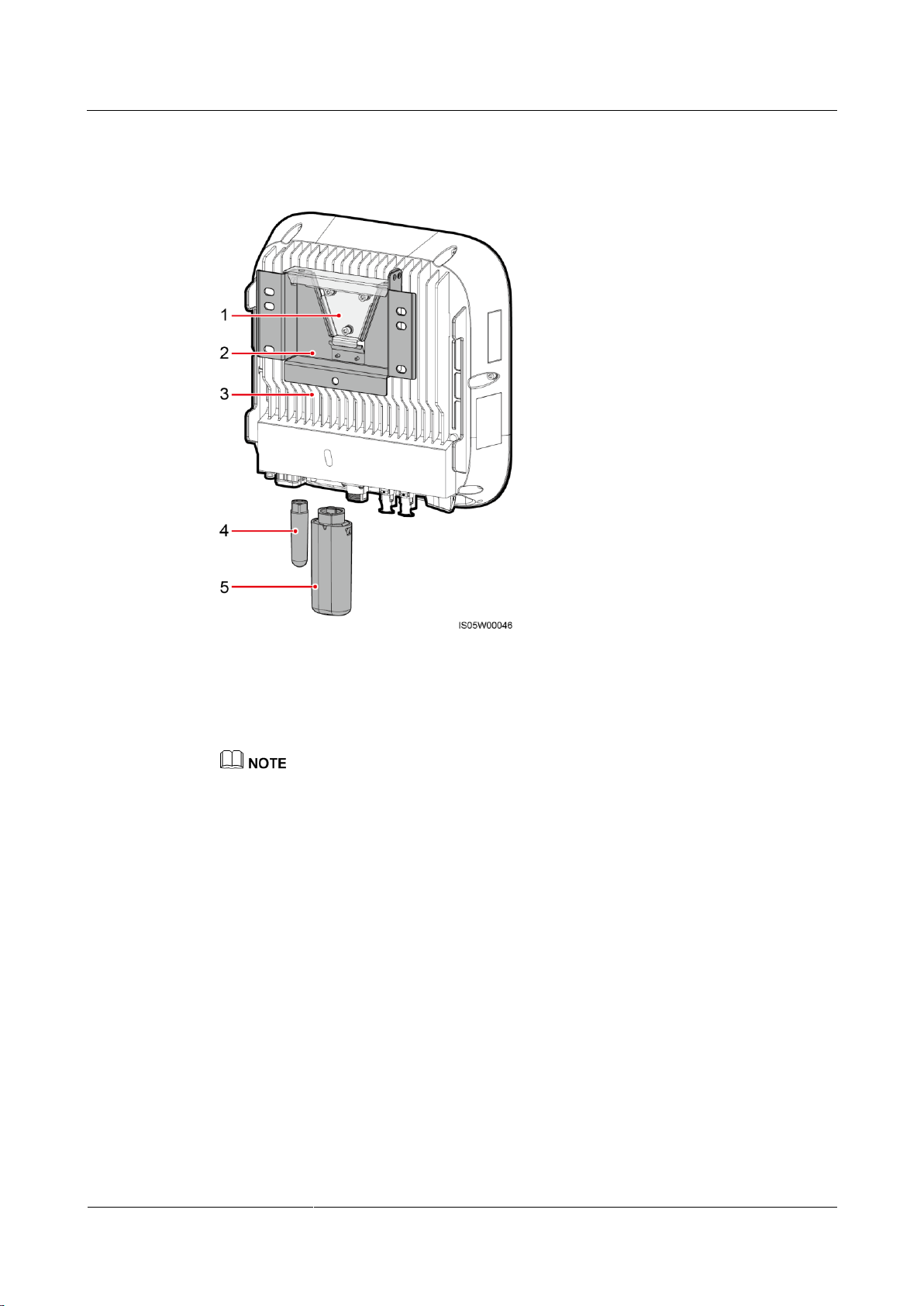
Rear view
(1) Mounting plate
(2) Mounting bracket
(3) Heat sink
(4) WiFi antenna (optional)
(5) 4G module (optional)
Figure 2-5 Rear view
Only either of the WiFi antenna and 4G module can be installed at the time of setup.
Page 16
SUN2000-(2KTL-5KTL)-L0
User Manual
2 Product Overview
Issue 01 (2018-08-30)
Copyright © Huawei Technologies Co., Ltd.
10
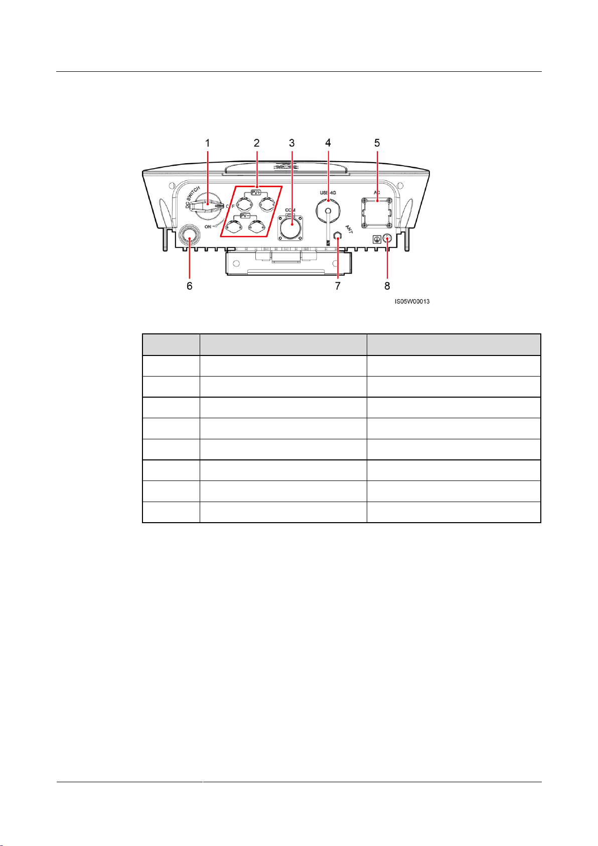
Bottom View
No.
Component
Silk Screen
1
DC switch
DC SWITCH
2
DC input terminals
PV+/PV–
3
COM port
COM
4
USB-4G port
USB-4G
5
AC output port
AC 6 Ventilation valve
N/A
7
Antenna port
ANT
8
Ground point
N/A
Figure 2-6 Bottom view
Page 17
SUN2000-(2KTL-5KTL)-L0
User Manual
2 Product Overview
Issue 01 (2018-08-30)
Copyright © Huawei Technologies Co., Ltd.
11
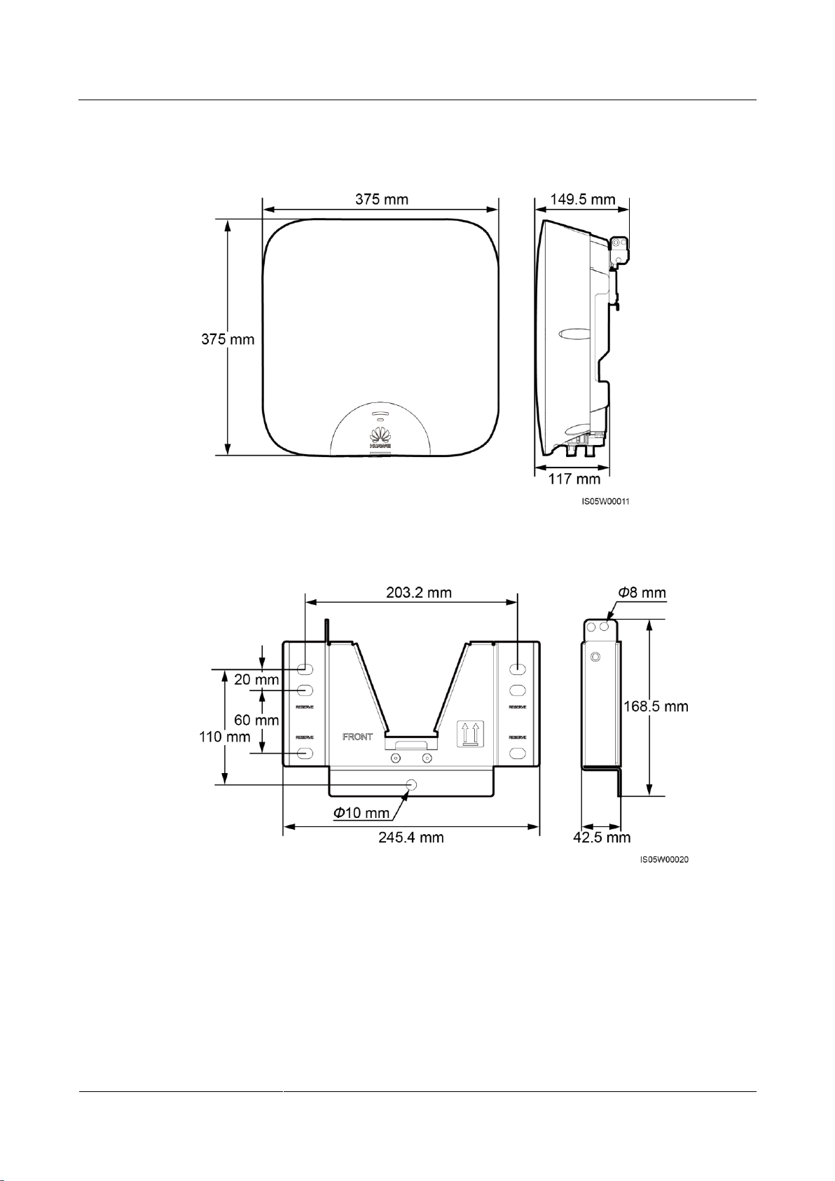
Dimensions
Figure 2-7 SUN2000 dimensions
Figure 2-8 Mounting bracket dimensions
Page 18
SUN2000-(2KTL-5KTL)-L0
User Manual
2 Product Overview
Issue 01 (2018-08-30)
Copyright © Huawei Technologies Co., Ltd.
12
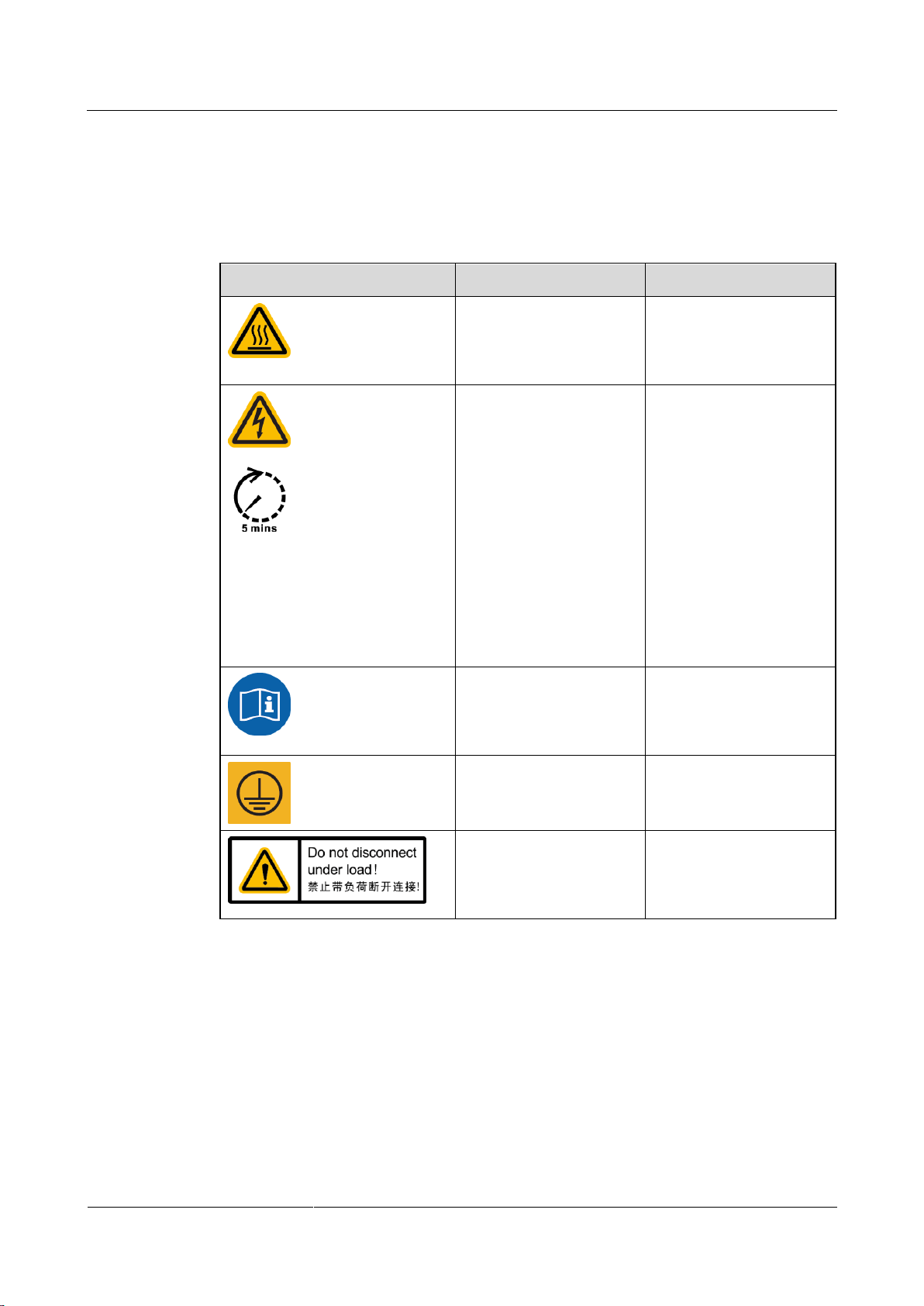
2.3 Label Descriptions
Symbol
Name
Meaning
Burn warning
Do not touch a running
SUN2000 because the
shell is hot when the
SUN2000 is running.
Delay discharge
High voltage exists
after the SUN2000 is
powered on. Only
qualified and trained
electrical technicians
are allowed to perform
operations on the
SUN2000.
Residual voltage exists
after the SUN2000 is
powered off. It takes 5
minutes for the
SUN2000 to discharge
to the safe voltage.
Refer to documentation
Reminds operators to
refer to the documents
supplied with the
SUN2000.
Grounding
Indicates the position for
connecting the protective
earthing (PE) cable.
Operation warning
Do not remove the
connector or antenna
when the SUN2000 is
running.
Labels
Table 2-3 Label description
Page 19
SUN2000-(2KTL-5KTL)-L0
User Manual
2 Product Overview
Issue 01 (2018-08-30)
Copyright © Huawei Technologies Co., Ltd.
13
Symbol
Name
Meaning
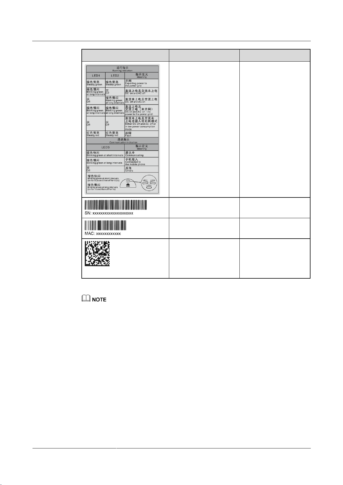
Indicator status
description label
Describes the indicator
status.
SUN2000 serial number
(SN) label
Indicates the SUN2000
SN.
SUN2000 MAC address
label
Indicates the MAC
address.
QR code for SUN2000
WiFi connection
Scan the QR code to
connect to Huawei
SUN2000 WiFi network
(Android) or obtain the
WiFi password (iOS).
The labels are for reference only.
Page 20
SUN2000-(2KTL-5KTL)-L0
User Manual
2 Product Overview
Issue 01 (2018-08-30)
Copyright © Huawei Technologies Co., Ltd.
14
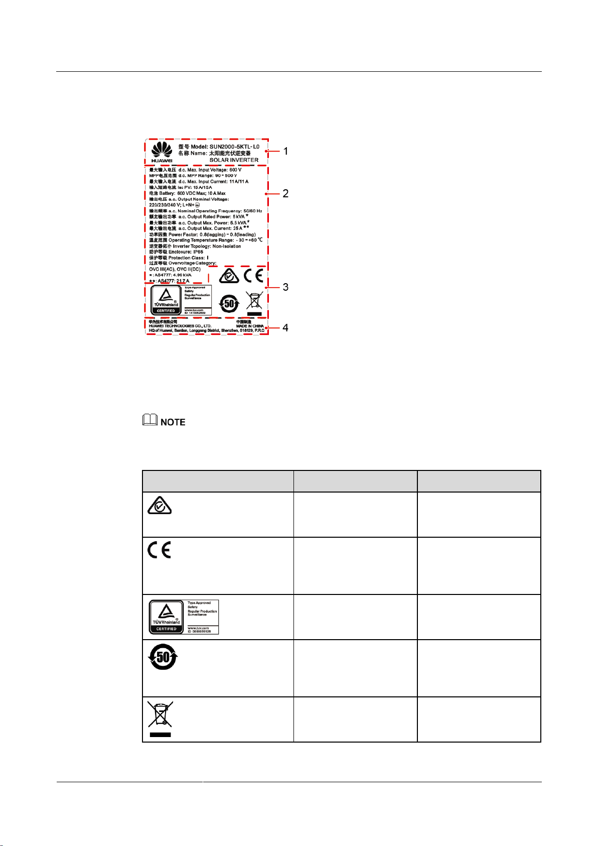
Nameplate
(1) Trademark and product model
(2) Important technical specifications
(3) Compliance symbols
(4) Company name and country of manufacture
Symbol
Name
Meaning
RCM certification mark
The SUN2000 complies
with RCM certification
standards.
CE certification mark
The SUN2000 complies
with Conformité
Européenne (CE)
certification standards.
TÜVRheinland
certification mark
The SUN2000 complies
with TÜVRheinland
certification standards.
Environment friendly use
period (EFUP) mark
The product does not
pollute the environment
during the specified
period.
EU waste electrical and
electronic equipment
(WEEE) mark
Do not dispose of the
product as household
garbage.
Figure 2-9 Nameplate of the SUN2000-5KTL-L0
The nameplate figure is for reference only.
Table 2-4 Compliance symbols
Page 21
SUN2000-(2KTL-5KTL)-L0
User Manual
2 Product Overview
Issue 01 (2018-08-30)
Copyright © Huawei Technologies Co., Ltd.
15
2.4 Working Principles
Conceptual Diagram
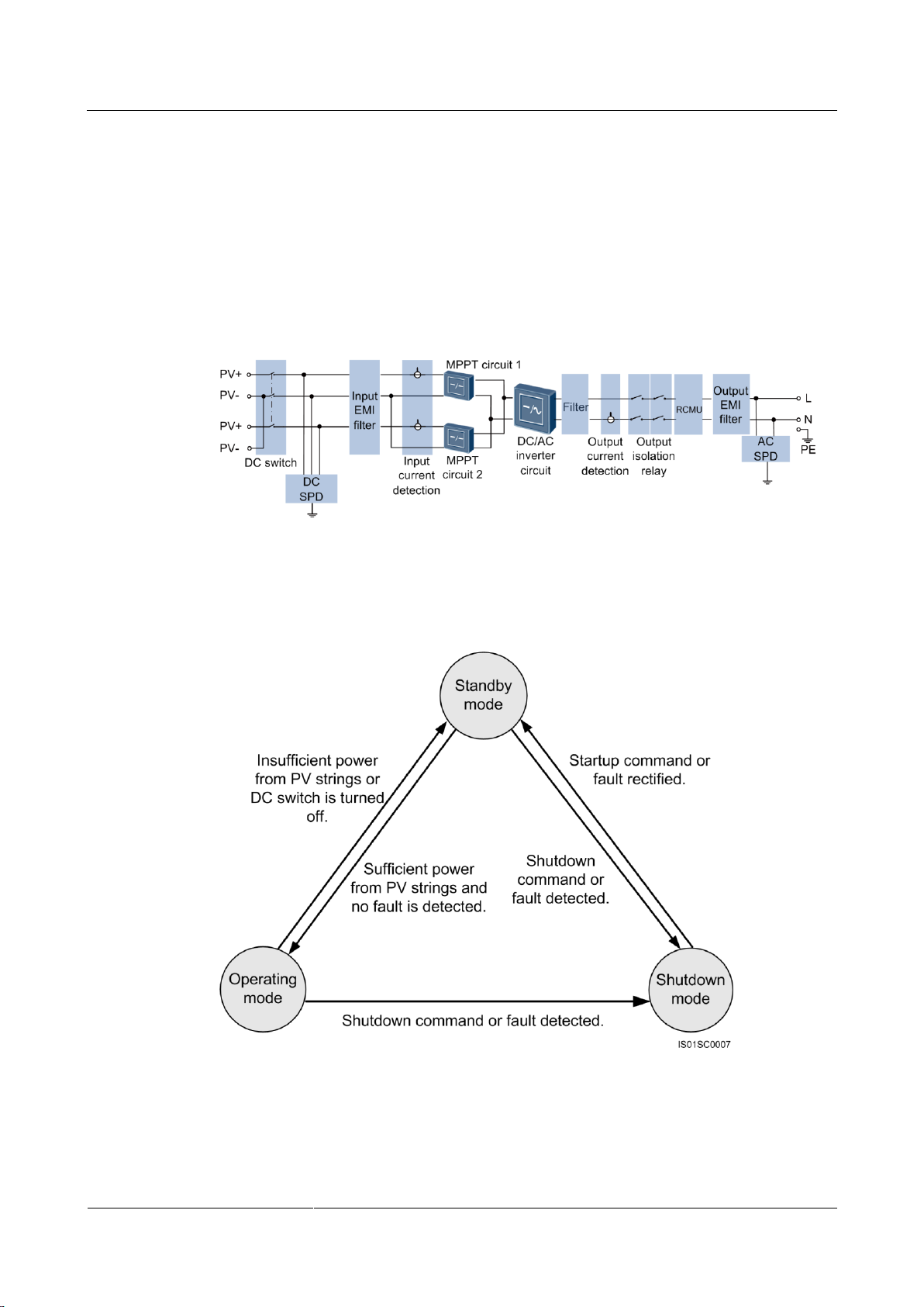
The SUN2000 receives two inputs from the two PV strings. Two MPPT circuits are
configured inside the SUN2000. Each circuit tracks the maximum power point of one PV
string respectively. The DC power is then converted into single-phase AC power through an
inverter circuit. Surge protection is supported on both the DC and AC sides.
Figure 2-10 Conceptual diagram
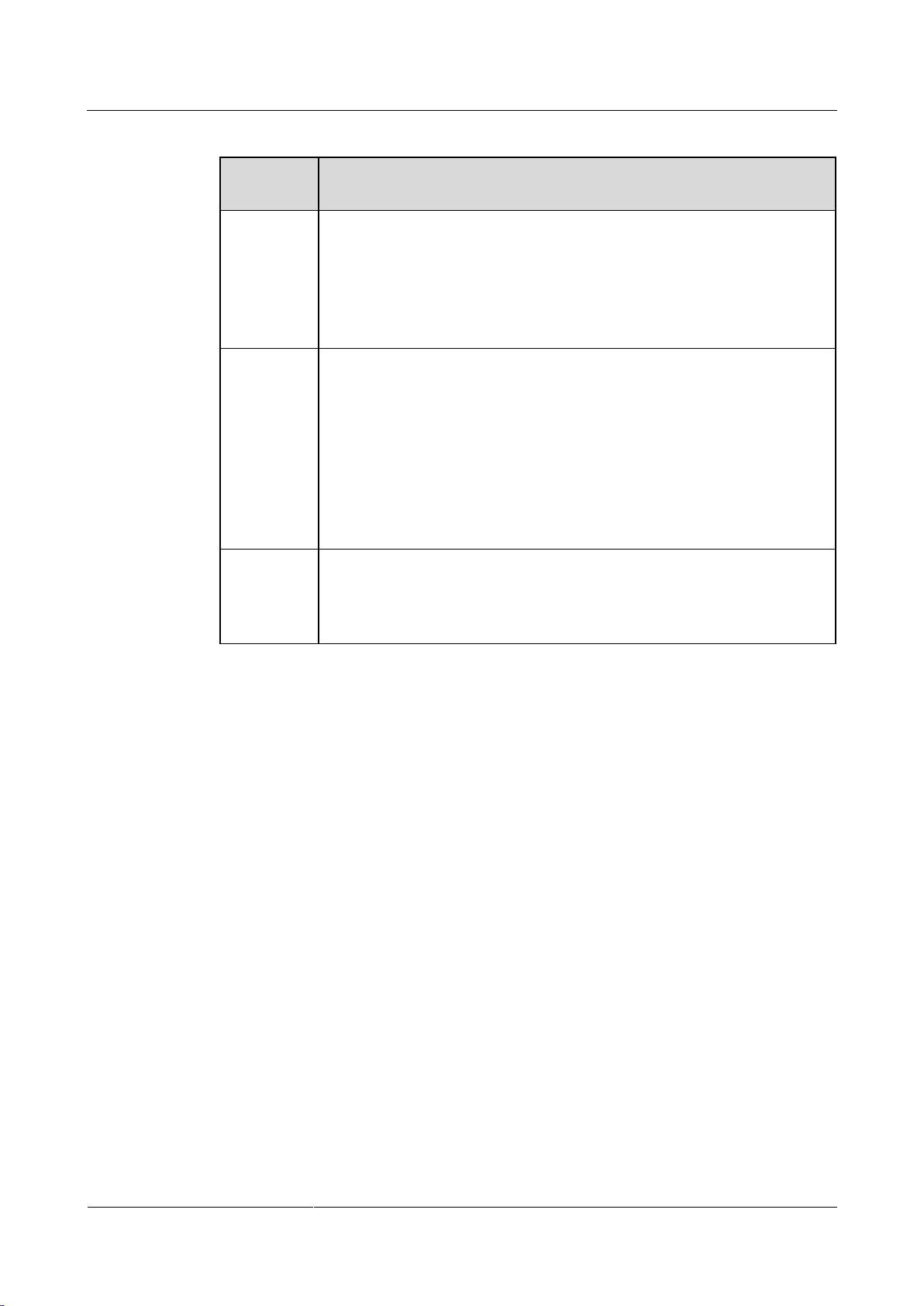
Working Modes
Figure 2-11 Working modes
Page 22
SUN2000-(2KTL-5KTL)-L0
User Manual
2 Product Overview
Issue 01 (2018-08-30)
Copyright © Huawei Technologies Co., Ltd.
16
Table 2-5 Working mode description
Working
Mode
Description
Standby
The SUN2000 enters Standby mode when the external environment does not
meet the requirements for starting the SUN2000. In Standby mode:
The SUN2000 continuously checks its status and enters Operating mode
once the operating requirements are met.
The SUN2000 enters Shutdown mode after detecting a shutdown
command or a fault after startup.
Operating
In Operating mode:
The SUN2000 converts DC power from PV strings into AC power and
feeds the energy to the power grid.
The SUN2000 tracks the maximum power point to maximize the PV
string output.
The SUN2000 enters Shutdown mode after detecting a fault or a
shutdown command, and enters Standby mode after detecting that the
PV string output power is not suitable for connecting to the power grid
and producing power.
Shutdown
In Standby or Operating mode, the SUN2000 enters Shutdown mode
after detecting a fault or shutdown command.
In Shutdown mode, the SUN2000 enters Standby mode after detecting a
startup command or that the fault is rectified.
Page 23

SUN2000-(2KTL-5KTL)-L0
User Manual
3 Storage
Issue 01 (2018-08-30)
Copyright © Huawei Technologies Co., Ltd.
17
3 Storage
The following requirements should be met when the SUN2000 needs to be stored prior to
installation:
Do not unpack the SUN2000.
Keep the storage temperature at –40°C to +70°C and the humidity at 5%–95% RH.
The SUN2000 should be stored in a clean and dry place and be protected from dust and
water vapor corrosion.
A maximum of 10 SUN2000s can be stacked. To avoid personal injury or device damage,
stack SUN2000s with caution to prevent them from falling over.
Regular inspection is required during the storage. Replace the packing materials when
necessary.
After long-term storage, the SUN2000 needs to be inspected and tested by qualified
persons before it is put into use.
Page 24
SUN2000-(2KTL-5KTL)-L0
User Manual
4 System Installation
Issue 01 (2018-08-30)
Copyright © Huawei Technologies Co., Ltd.
18
4 System Installation
4.1 Checking Before Installation
Outer Packing Materials
Before unpacking the SUN2000, check the outer packing materials for damage, such as holes
and cracks, and check the SUN2000 model. If any damage is found or the SUN2000 model is
not what you requested, do not unpack the product and contact your supplier as soon as
possible.
You are advised to remove the packing materials no more than 24 hours before installing the
SUN2000.
Package Contents
After unpacking the SUN2000, check that the contents are intact and complete. If any damage
is found or any component is missing, contact your supplier.
For details about the number of contents, see the Packing List in the packing case.
Page 25
SUN2000-(2KTL-5KTL)-L0
User Manual
4 System Installation
Issue 01 (2018-08-30)
Copyright © Huawei Technologies Co., Ltd.
19
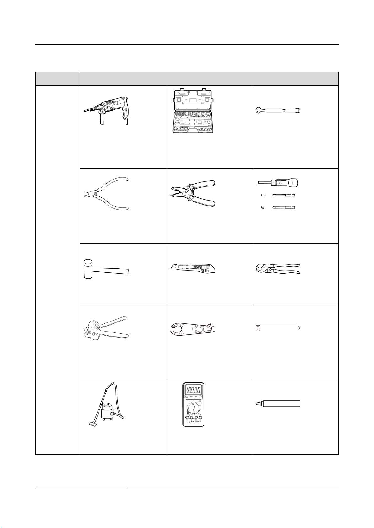
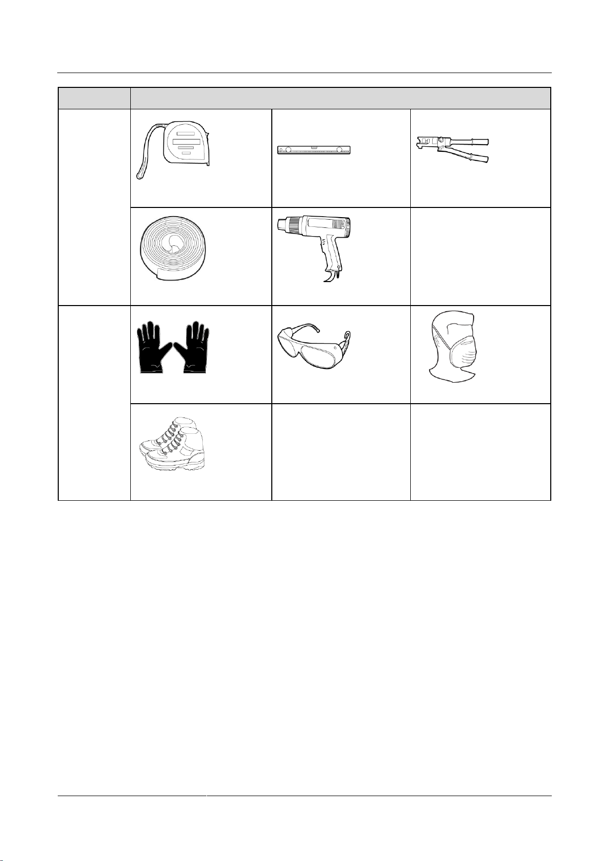
4.2 Tools and Instruments
Category
Tools and Instruments
Installation
Hammer drill (with a Ф10
mm drill bit)
Torque socket wrench (open
end: 13 mm, applicable for
M8 bolts; torque range: 0–15
N•m)
Torque wrench (open end: 13
mm; torque range: 0–1.5
N•m)
Diagonal pliers
Wire stripper
Torque screwdriver (head:
M4 or M6; torque range: 0–5
N•m)
Rubber mallet
Utility knife
Cable cutter
Crimping tool (model:
H4TC0001; manufacturer:
Amphenol)
Open-end wrench (model:
H4TW0001; manufacturer:
Amphenol)
Cable tie
Vacuum cleaner
Multimeter (DC voltage
measurement range ≥ 600 V
DC)
Marker
Page 26
SUN2000-(2KTL-5KTL)-L0
User Manual
4 System Installation
Issue 01 (2018-08-30)
Copyright © Huawei Technologies Co., Ltd.
20
Category
Tools and Instruments
Measuring tape
Bubble or digital level
Hydraulic pliers
Heat shrink tubing
Heat gun
N/A
PPE
Safety gloves
Safety goggles
Anti-dust respirator
Safety shoes
N/A
N/A
4.3 Determining the Installation Position
Basic Requirements
The SUN2000 is protected to IP65 and can be installed indoors or outdoors.
Do not install the SUN2000 in a place where a person can easily touch it because its
enclosure and heat sinks are extremely hot during operation.
Do not install the SUN2000 in areas with flammable or explosive materials.
Do not install the SUN2000 at a place within children's reach.
Do not install the SUN2000 outdoors in salt areas because it will be corroded there and
may cause fire. A salt area refers to the region within 500 meters from the coast or prone
to sea breeze. The regions prone to sea breeze vary depending on weather conditions
(such as typhoons and monsoons) or terrains (such as dams and hills).
Page 27
SUN2000-(2KTL-5KTL)-L0
User Manual
4 System Installation
Issue 01 (2018-08-30)
Copyright © Huawei Technologies Co., Ltd.
21
Installation Environment Requirements
The SUN2000 must be installed in a well-ventilated environment to ensure good heat
dissipation.
When installed under direct sunlight, the power of the SUN2000 may be derated due to
additional temperature rise.
Install the SUN2000 in a sheltered place or install an awning over the SUN2000.
Mounting Structure Requirements
The mounting structure where the SUN2000 is installed must be fireproof.
Do not install the SUN2000 on flammable building materials.
Ensure that the installation surface is solid enough to bear the weight load.
In residential areas, do not install the SUN2000 on drywalls or walls made of similar
materials which have a weak sound insulation performance because the noise generated
by the SUN2000 is noticeable.
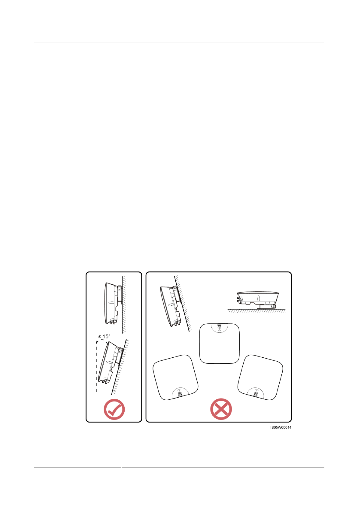
Installation Angle Requirements
The SUN2000 can be wall-mounted or pole-mounted. The installation angle requirements are
as follows:
Install the SUN2000 vertically or at a maximum back tilted angle of 15 degrees to
facilitate heat dissipation.
Do not install the SUN2000 at forward tilted, excessively back tilted, side tilted,
horizontal, or upside down positions.
Figure 4-1 Installation angle
Page 28
SUN2000-(2KTL-5KTL)-L0
User Manual
4 System Installation
Issue 01 (2018-08-30)
Copyright © Huawei Technologies Co., Ltd.
22
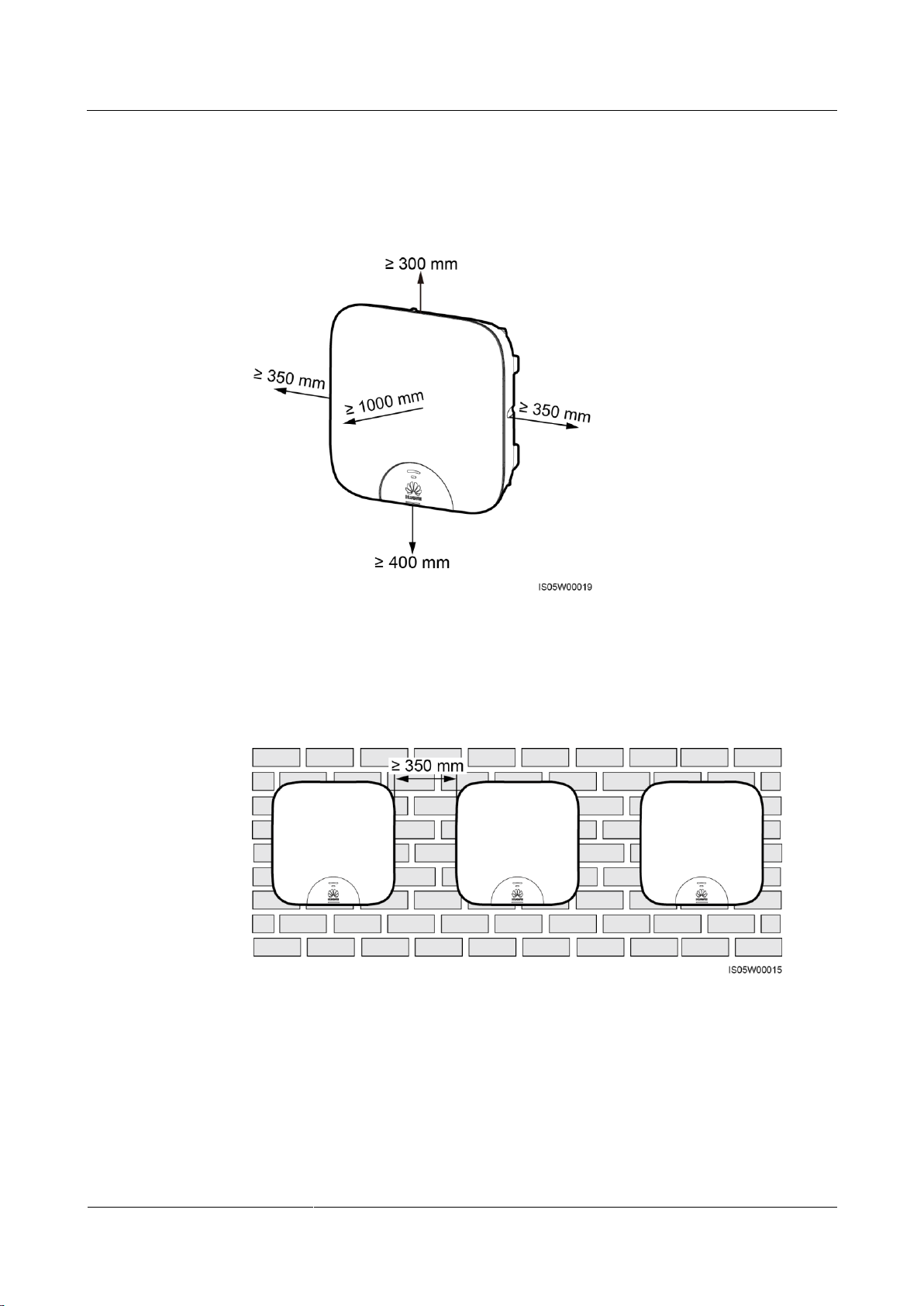
Installation Clearance Requirements
Reserve enough clearance around the SUN2000 to ensure sufficient space for installation
and heat dissipation.
Figure 4-2 Installation clearance requirements
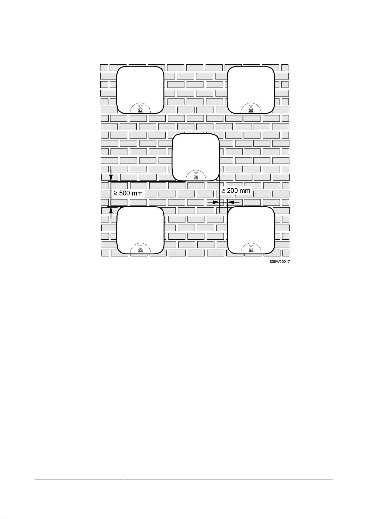
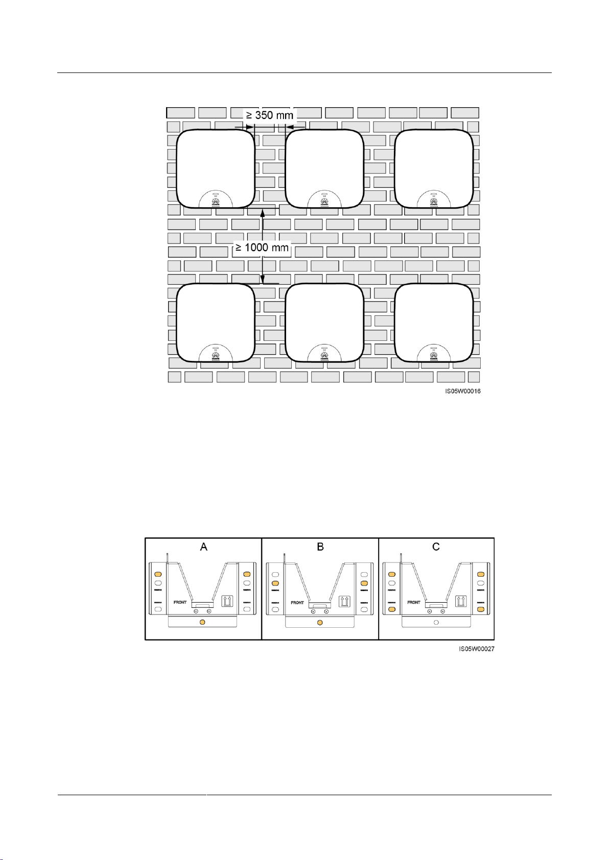
When installing multiple SUN2000s, install them in horizontal mode if the space is
sufficient and install them in staggered mode if the space is insufficient. Stacked
installation is not recommended.
Figure 4-3 Horizontal installation mode (recommended)
Page 29
SUN2000-(2KTL-5KTL)-L0
User Manual
4 System Installation
Issue 01 (2018-08-30)
Copyright © Huawei Technologies Co., Ltd.
23
Figure 4-4 Staggered installation mode (recommended)
Page 30
SUN2000-(2KTL-5KTL)-L0
User Manual
4 System Installation
Issue 01 (2018-08-30)
Copyright © Huawei Technologies Co., Ltd.
24
Figure 4-5 Stacked installation mode (not recommended)
4.4 Installing the Mounting Bracket
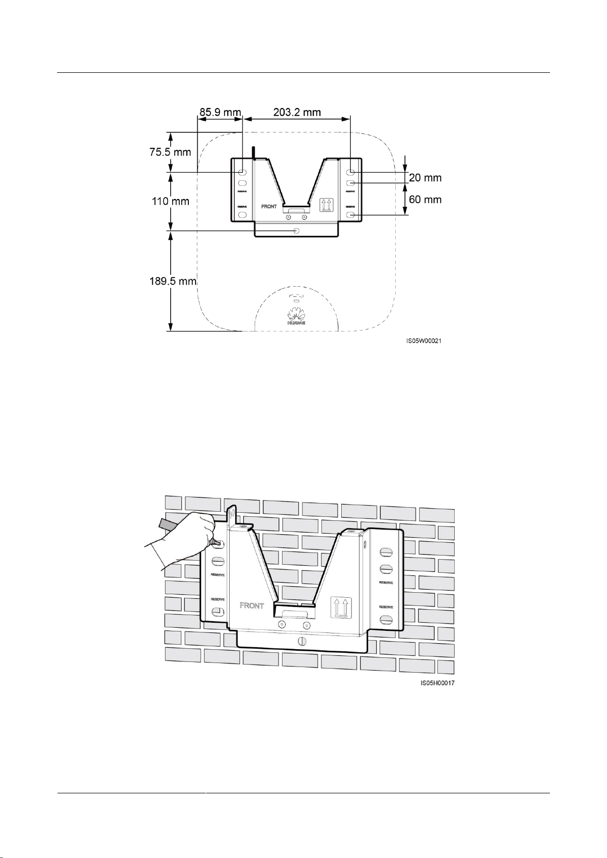
Fixing holes can be used in three combinations. Select a hole combination based on site
requirements. Combination A is preferred.
Figure 4-6 Hole combinations
Page 31
SUN2000-(2KTL-5KTL)-L0
User Manual
4 System Installation
Issue 01 (2018-08-30)
Copyright © Huawei Technologies Co., Ltd.
25
Figure 4-7 Hole distances
4.4.1 Wall-Mounted Installation
Procedure
Step 1 Determine the positions for drilling holes using the mounting bracket. Level the positions of
mounting holes using a bubble or digital level, and mark the positions with a marker.
Figure 4-8 Determining hole positions
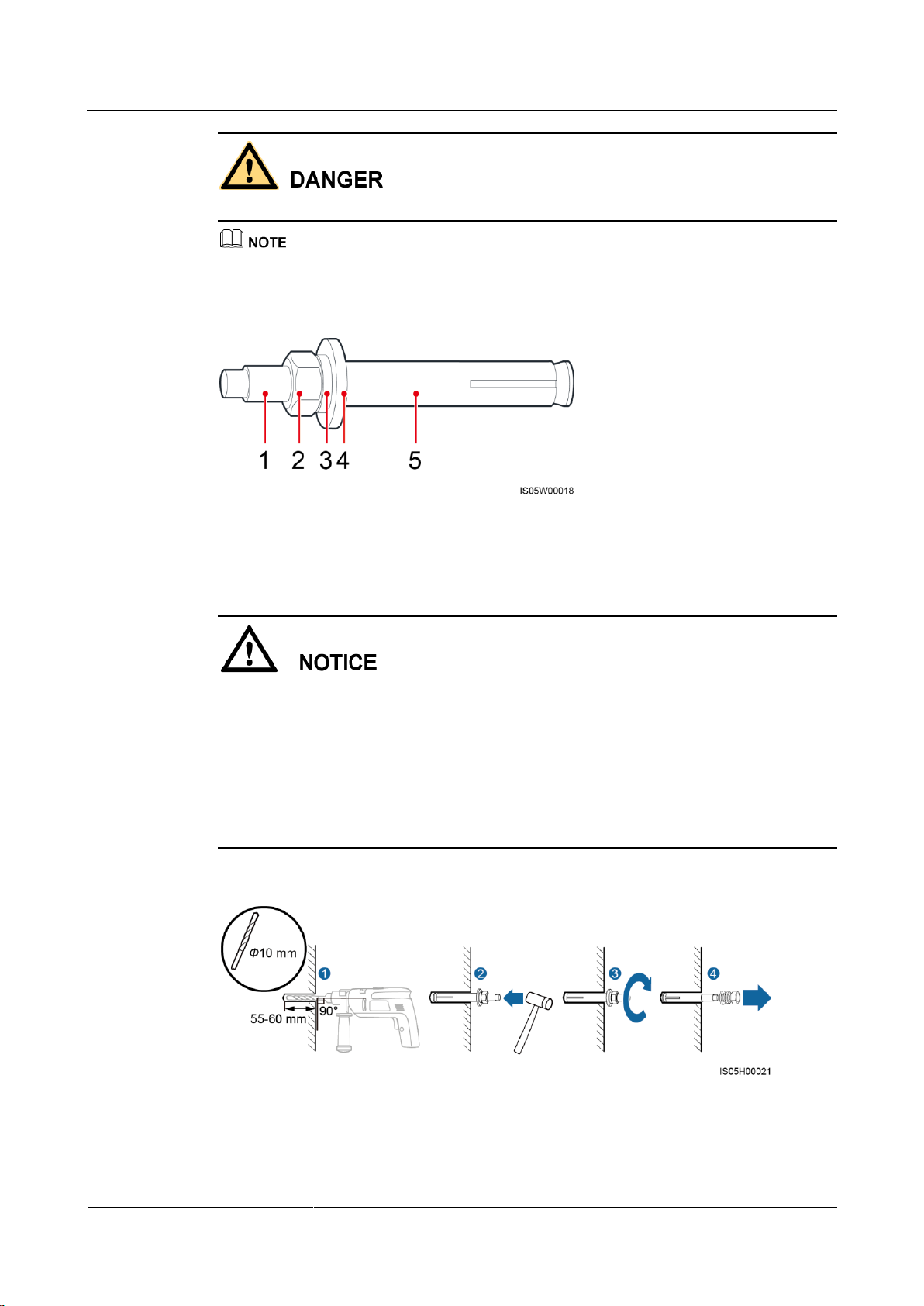
Step 2 Install expansion bolts.
Page 32
SUN2000-(2KTL-5KTL)-L0
User Manual
4 System Installation
Issue 01 (2018-08-30)
Copyright © Huawei Technologies Co., Ltd.
26
(1) Bolt
(2) Nut
(3) Spring washer
(4) Flat washer
(5) Expansion sleeve
Avoid drilling holes in the utility pipes and/or cables attached to back of the wall.
If the length or number of M8x80 expansion bolts supplied with the SUN2000 is not enough, prepare
M8 stainless steel expansion anchor bolts.
Figure 4-9 Expansion bolt composition
To prevent dust inhalation or contact with eyes, wear safety goggles and an anti-dust
respirator when drilling holes.
Clean up any dust in and around the holes using a vacuum cleaner and measure the
distance between holes. If the holes are inaccurately positioned, drill a new set of the
holes.
Level the head of the expansion sleeve with the concrete wall after removing the bolt,
spring washer, and flat washer. Otherwise, the mounting bracket will not be securely
installed on the concrete wall.
Figure 4-10 Installing an expansion bolt
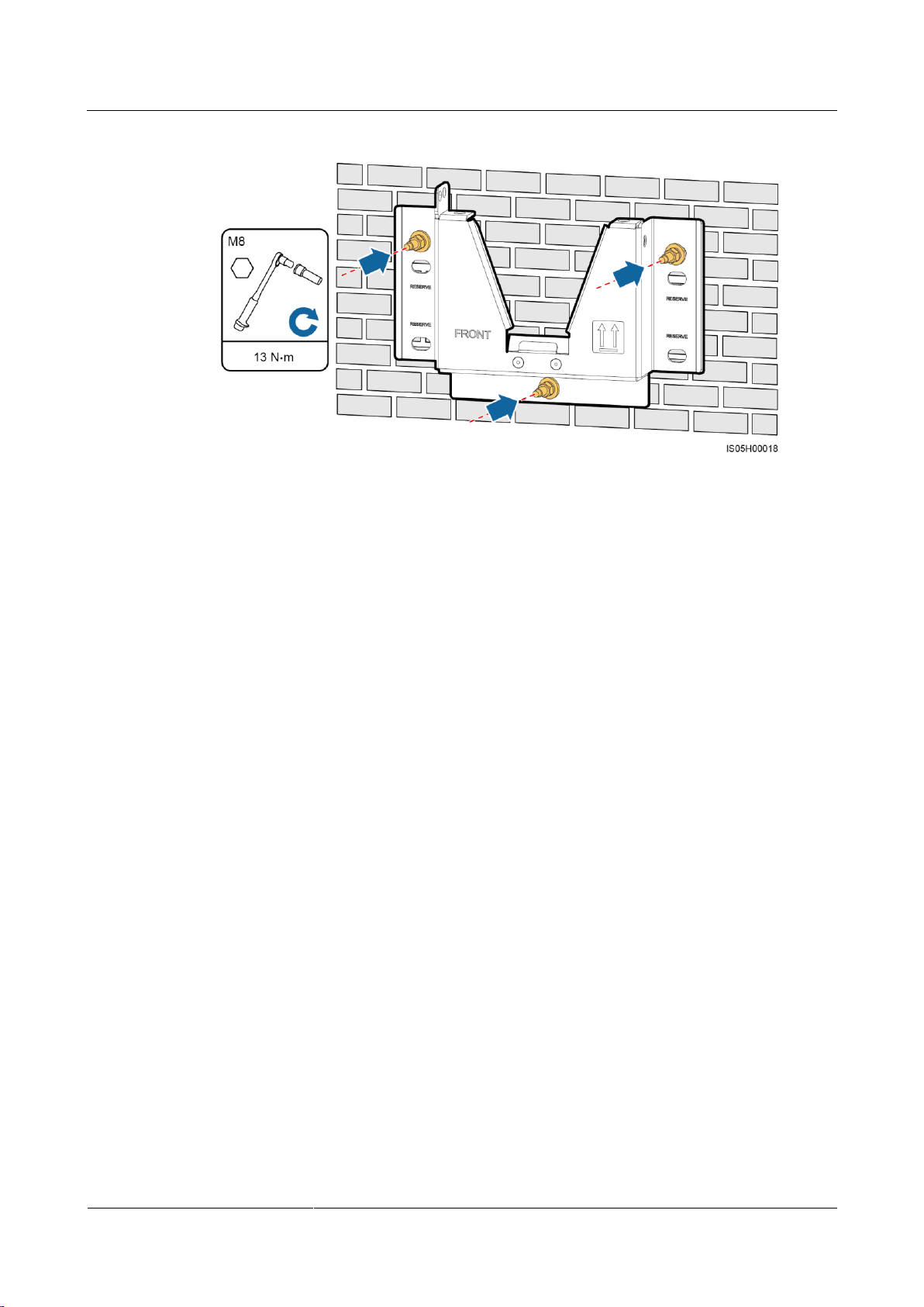
Step 3 Secure the mounting bracket.
Page 33
SUN2000-(2KTL-5KTL)-L0
User Manual
4 System Installation
Issue 01 (2018-08-30)
Copyright © Huawei Technologies Co., Ltd.
27
Figure 4-11 Securing a mounting bracket
----End
4.4.2 Support-mounted Installation
Prerequisites
Procedure
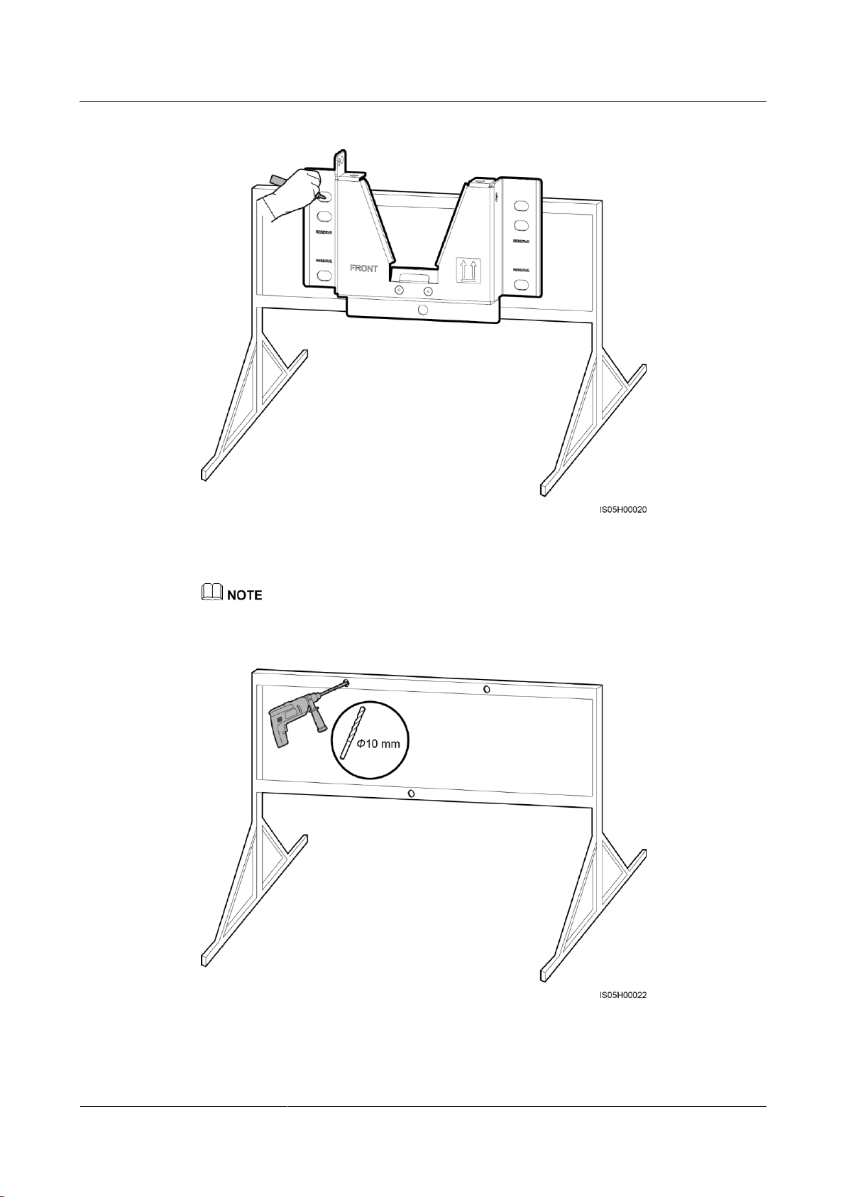
Step 1 Determine the positions for drilling holes using the mounting bracket. Level the positions of
Prepare M8 stainless bolt assemblies (including flat washers, spring washers, and M8 bolts)
with appropriate lengths as well as matched flat washers and nuts based on the support
specifications.
mounting holes using a bubble or digital level, and mark the positions with a marker.
Page 34
SUN2000-(2KTL-5KTL)-L0
User Manual
4 System Installation
Issue 01 (2018-08-30)
Copyright © Huawei Technologies Co., Ltd.
28
Figure 4-12 Determining hole positions
Step 2 Drill holes using a hammer drill.
You are advised to apply anti-rust paint on the hole positions for protection.
Figure 4-13 Drilling holes
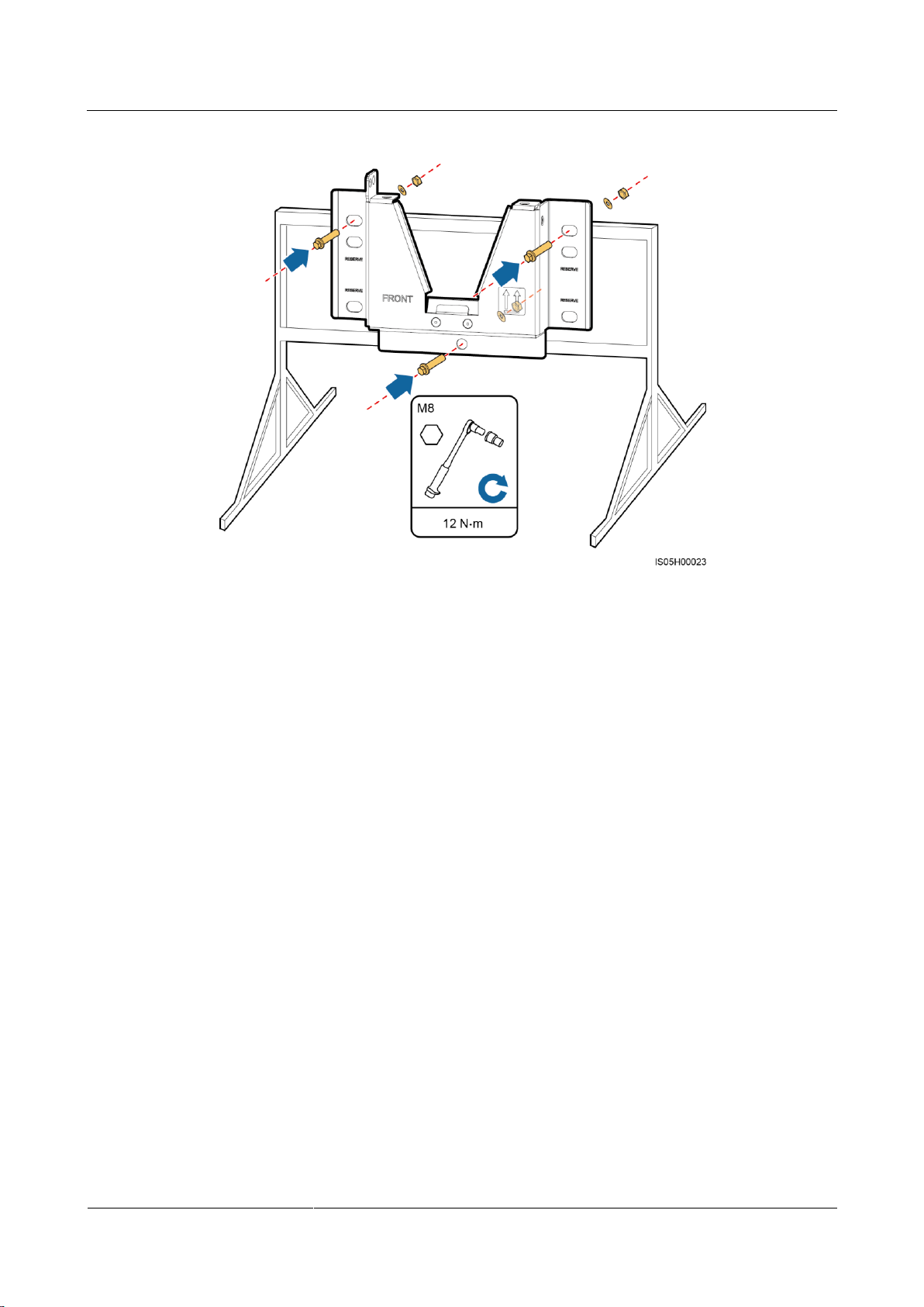
Step 3 Secure the mounting bracket.
Page 35
SUN2000-(2KTL-5KTL)-L0
User Manual
4 System Installation
Issue 01 (2018-08-30)
Copyright © Huawei Technologies Co., Ltd.
29
Figure 4-14 Securing a mounting bracket
----End
4.5 Installing the SUN2000
Procedure
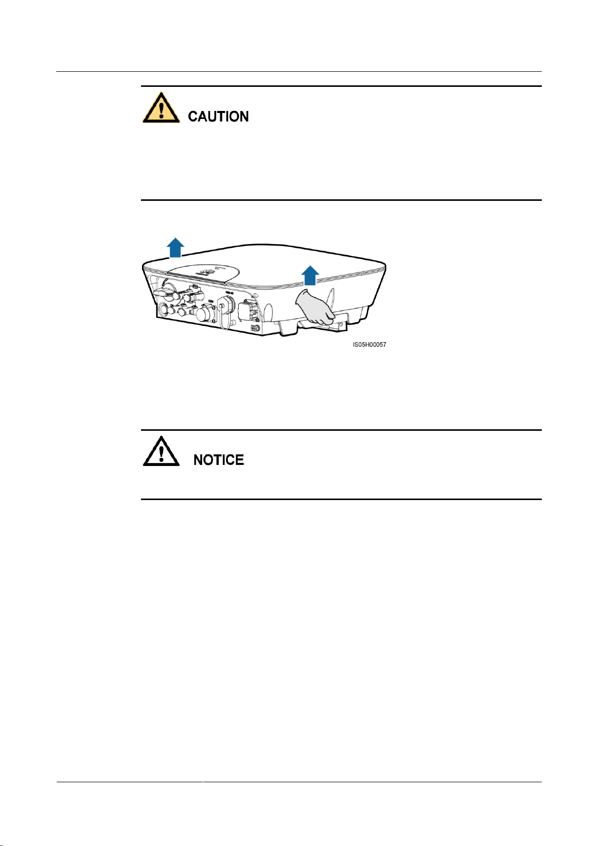
Step 1 Hold the handles on both sides of the SUN2000, lift the SUN2000 from the packing case, and
transport it to the installation position.
Page 36
SUN2000-(2KTL-5KTL)-L0
User Manual
4 System Installation
Issue 01 (2018-08-30)
Copyright © Huawei Technologies Co., Ltd.
30
To prevent device damage and personal injury, keep balance when moving the SUN2000.
Do not use the ports and wiring terminals at the bottom to support any weight of the
SUN2000.
When you need to temporally place the SUN2000 on the ground, use foam, paper or other
protection material to prevent damage to its cover.
Figure 4-15 Moving a SUN2000
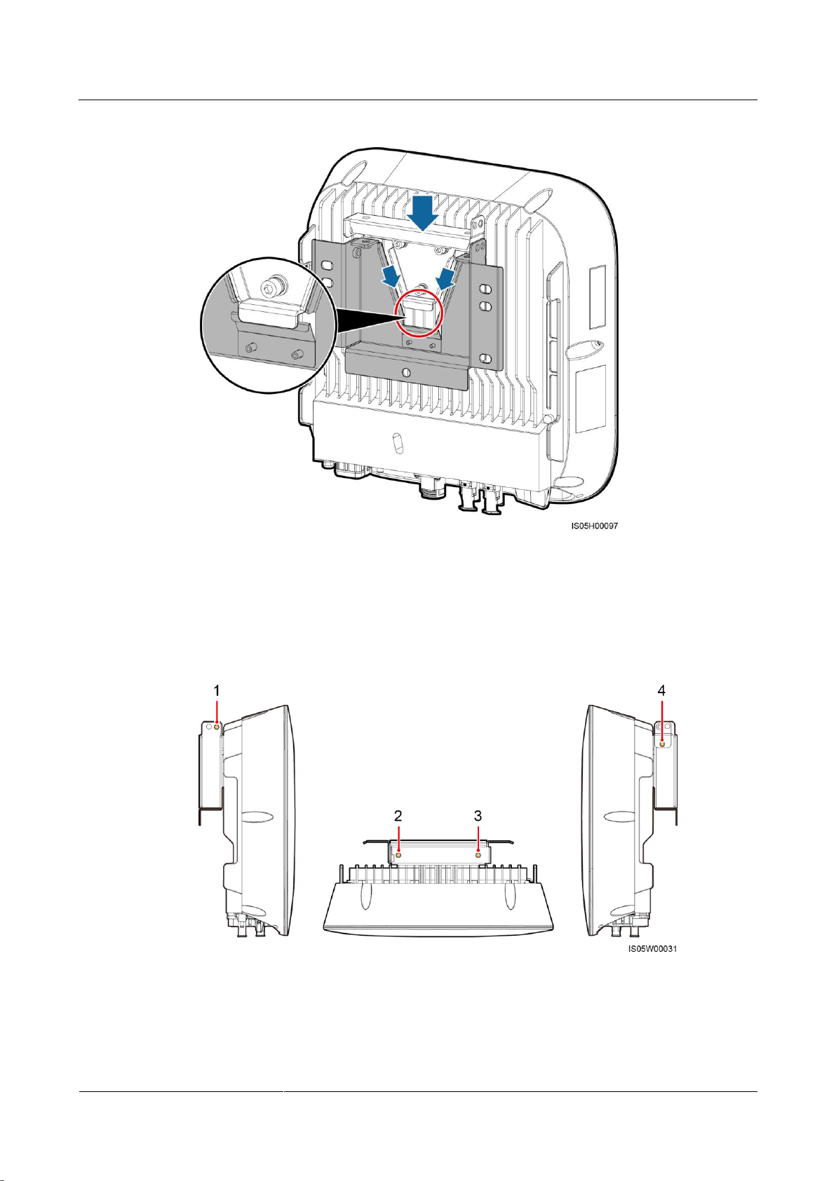
Step 2 Install the SUN2000 on the mounting bracket and align the SUN2000 enclosure with the
mounting bracket.
If the bottom of the mounting plate does not snap into place, push the SUN2000 from the
front until the bottom of the mounting plate snaps into the mounting bracket.
Page 37
SUN2000-(2KTL-5KTL)-L0
User Manual
4 System Installation
Issue 01 (2018-08-30)
Copyright © Huawei Technologies Co., Ltd.
31
Figure 4-16 Mounting a SUN2000
Combination A: holes 2 and 3
Combination B: holes 1 and 3
Combination C: holes 1 and 4
Combination D: holes 2 and 4
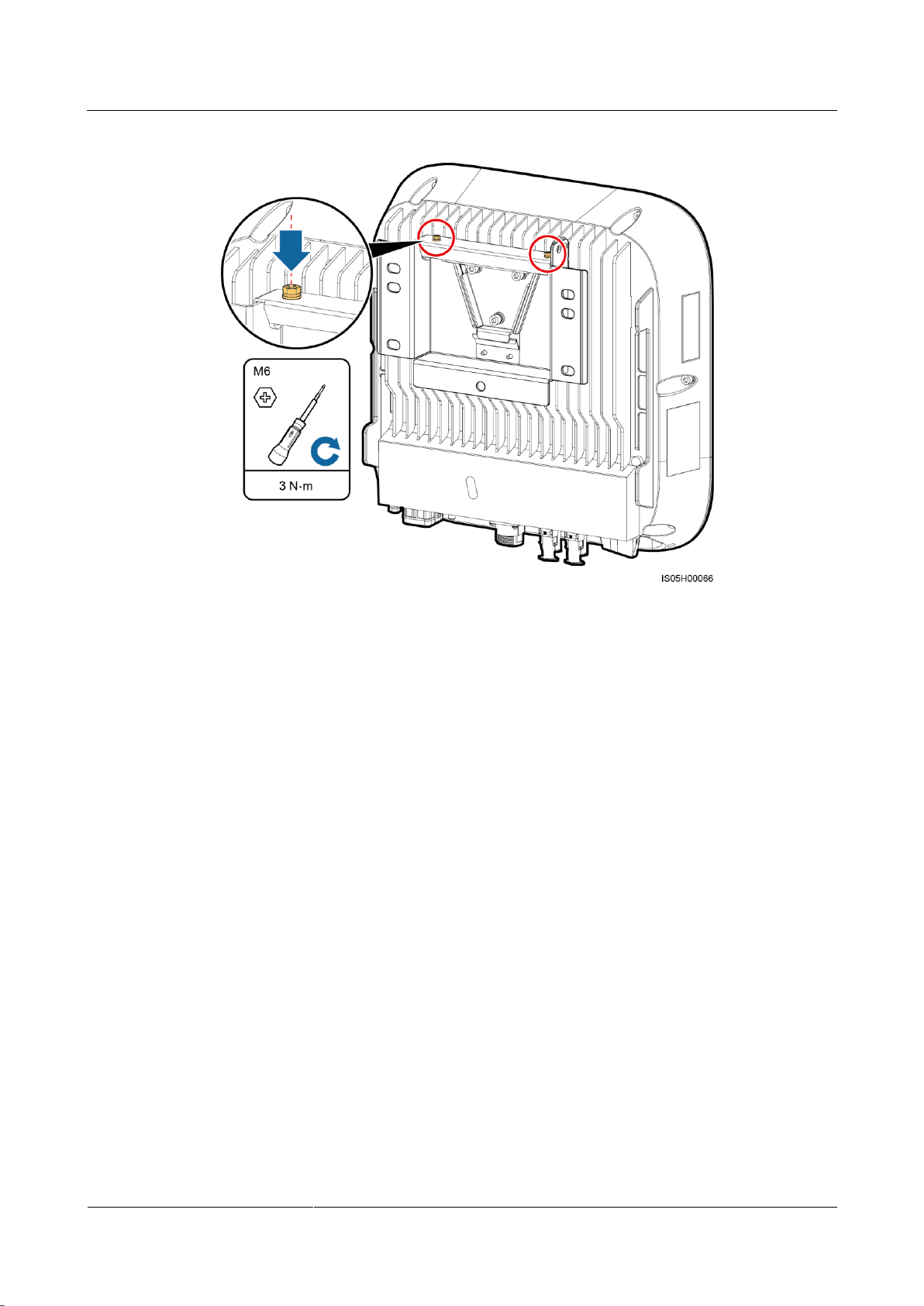
Step 3 Tighten screw assemblies.
Fixing holes can be used in three combinations. Select a hole combination based on site
requirements. Combination A is preferred.
Figure 4-17 Fixing holes
Page 38
SUN2000-(2KTL-5KTL)-L0
User Manual
4 System Installation
Issue 01 (2018-08-30)
Copyright © Huawei Technologies Co., Ltd.
32
Figure 4-18 Tightening screw assemblies
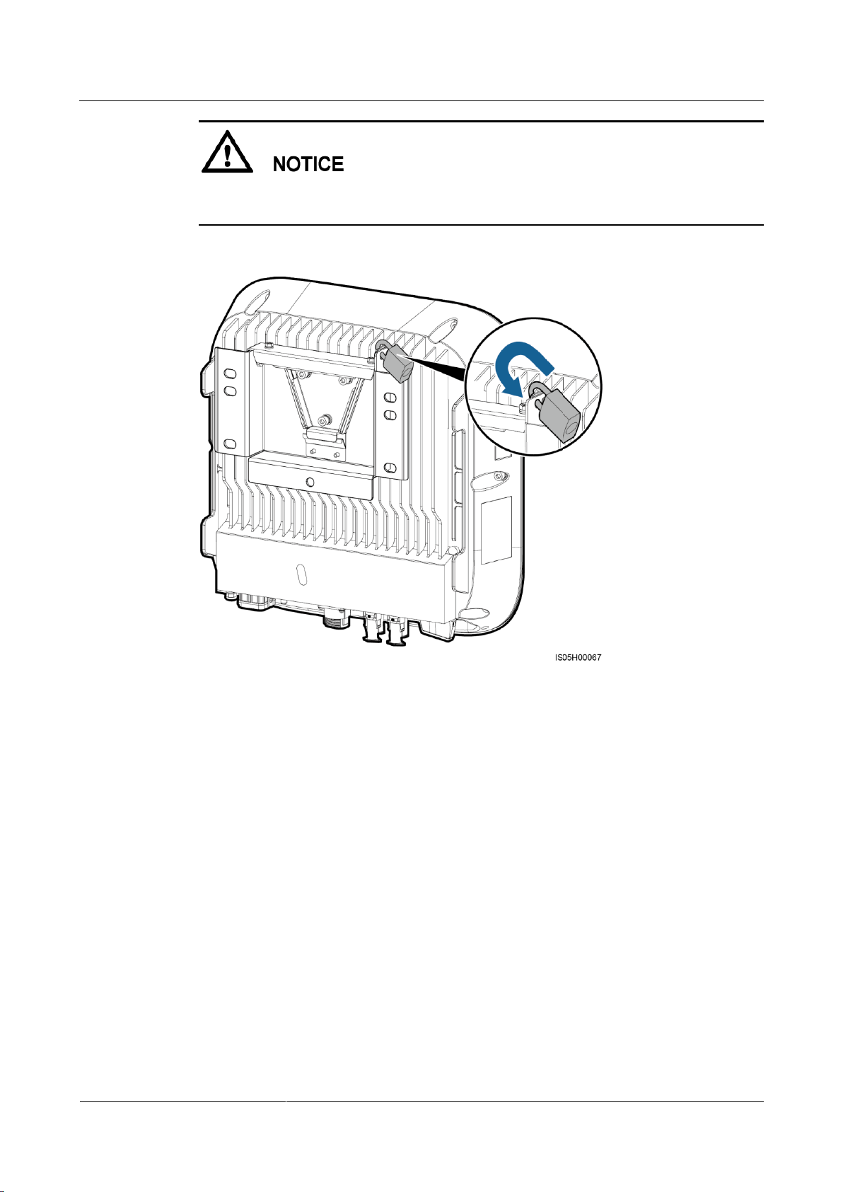
Step 4 (Optional) Install an anti-theft lock.
The function of an anti-theft lock is to secure the SUN2000 to the mounting bracket and
protect it from stealing.
Page 39
SUN2000-(2KTL-5KTL)-L0
User Manual
4 System Installation
Issue 01 (2018-08-30)
Copyright © Huawei Technologies Co., Ltd.
33
Prepare an anti-theft lock suitable for the lock hole diameter (Ф8 mm) by yourself.
Keep the key to the anti-theft lock safe.
Figure 4-19 Installing an anti-theft lock
----End
4.6 (Optional) Installing the WiFi Antenna
Prerequisites
A WiFi antenna is configured.
Context
Only either of the WiFi antenna and 4G module can be installed at the time of setup.
Procedure
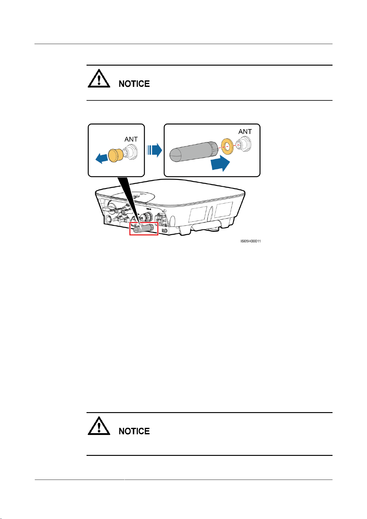
Step 1 Remove the watertight cap from the ANT port.
Step 2 Attach the washer to the enclosure.
Step 3 Install the WiFi antenna.
Page 40
SUN2000-(2KTL-5KTL)-L0
User Manual
4 System Installation
Issue 01 (2018-08-30)
Copyright © Huawei Technologies Co., Ltd.
34
Ensure that the WiFi antenna is installed securely.
Figure 4-20 Installing a WiFi antenna
----End
4.7 (Optional) Installing the 4G Module
Prerequisites
A 4G module is configured.
A subscriber identity module (SIM) card complying with the 4G module specifications is
prepared.
Ensure that the SIM card is activated.
Context
Only either of the WiFi antenna and 4G module can be installed at the time of setup.
The USB-4G port can only be used for the access from a 4G module, rather than a USB data
cable.
Page 41
SUN2000-(2KTL-5KTL)-L0
User Manual
4 System Installation
Issue 01 (2018-08-30)
Copyright © Huawei Technologies Co., Ltd.
35
Procedure
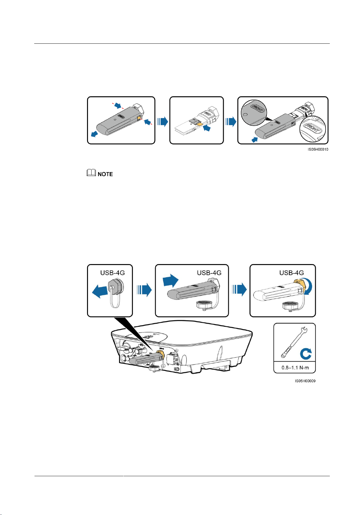
Step 1 Press the buckle inwards to remove the 4G module enclosure, and then install the SIM card.
Figure 4-21 Installing a SIM card
When installing a SIM card, you can determine the SIM card installation direction based on the
arrow mark on the slot.
When being pressed into place, the SIM card will be locked, which means that the card is installed
correctly.
To remove the SIM card, push it inwards. Then the SIM card springs out automatically.
When reinstalling the 4G module enclosure, ensure that the buckle springs back to the original
position.
Step 2 Remove the watertight cap from the USB-4G port and fix the 4G module.
Figure 4-22 Fixing a 4G module
----End
Page 42
SUN2000-(2KTL-5KTL)-L0
User Manual
5 Electrical Connections
Issue 01 (2018-08-30)
Copyright © Huawei Technologies Co., Ltd.
36
Precautions
5 Electrical Connections
Before connecting cables, ensure that the DC switch on the SUN2000 and all the switches
connecting to the SUN2000 are OFF. Otherwise, the high voltage of the SUN2000 may result
in electric shocks.
The equipment damage caused by incorrect cable connections is beyond the warranty
scope.
Only certified electricians are allowed to connect cables.
Operation personnel must wear proper PPE when connecting cables.
The cable colors shown in the electrical connection diagrams provided in this chapter are for reference
only. Select cables in accordance with local cable specifications (green-and-yellow cables are only used
for PE).
Page 43
SUN2000-(2KTL-5KTL)-L0
User Manual
5 Electrical Connections
Issue 01 (2018-08-30)
Copyright © Huawei Technologies Co., Ltd.
37
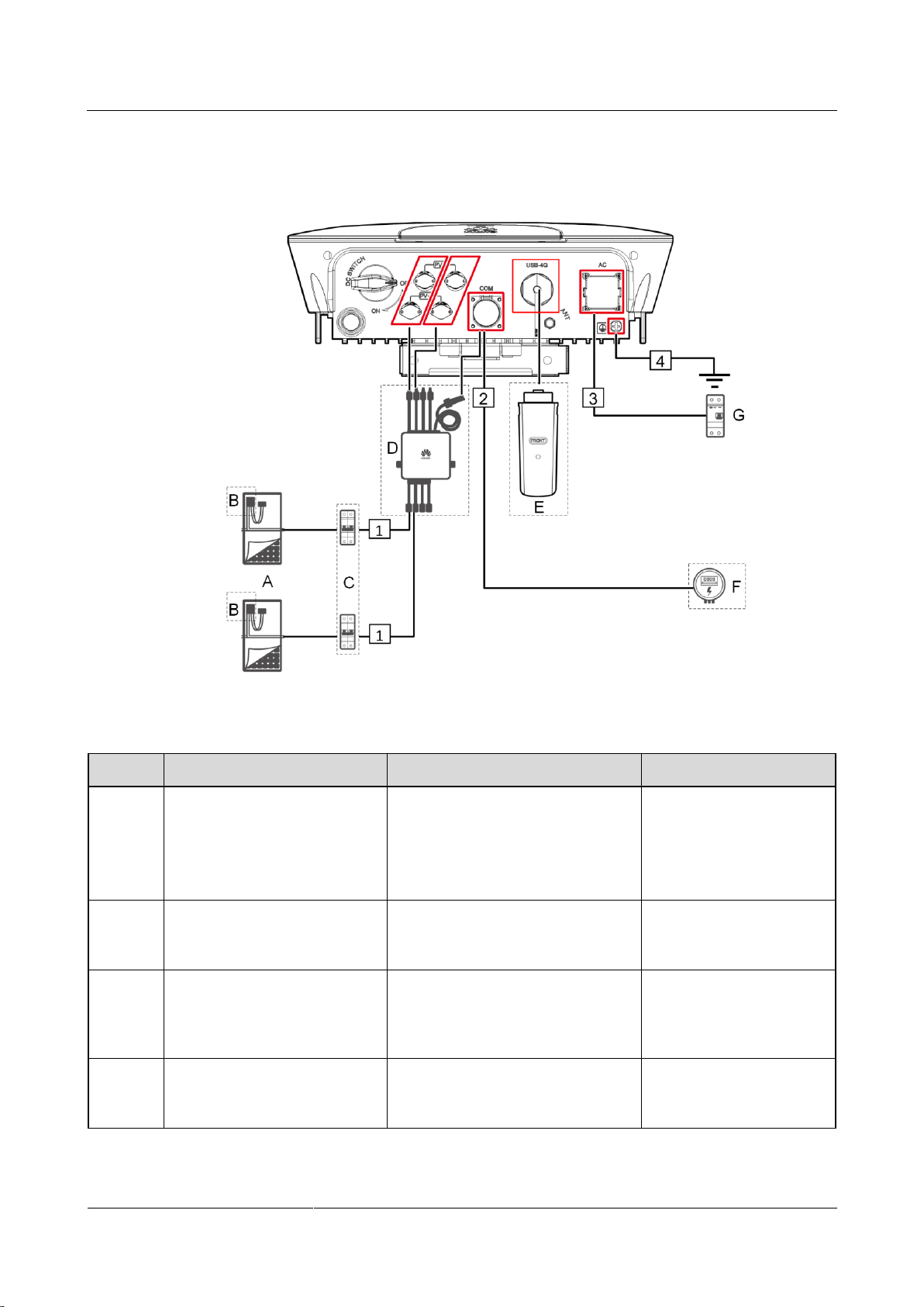
5.1 Preparing Cables
No.
Component
Description
Source
A
PV string
A PV string is composed of the
PV modules connected in series
and works with an optimizer.
The SUN2000 supports the input
from two PV strings.
Purchased by the customer
B
Smart PV Optimizer
The Smart PV Optimizer that can
connect to the SUN2000 is
SUN2000P-375W.
Can be purchased from
Huawei
C
DC switch
Recommended: a DC circuit
breaker with a rated voltage greater
than or equal to 600 V DC and a
rated current of 20 A.
Purchased by the customer
D
Smart PV Safety Box
The Smart PV Safety Box that can
connect to the SUN2000 is
SmartPSB2000L.
Can be purchased from
Huawei
Figure 5-1 SUN2000 cable connections (dashed boxes indicate optional components)
Table 5-1 Component description
Page 44
SUN2000-(2KTL-5KTL)-L0
User Manual
5 Electrical Connections
Issue 01 (2018-08-30)
Copyright © Huawei Technologies Co., Ltd.
38
No.
Component
Description
Source
E
4G module
The 4G module that can connect to
the SUN2000 is Smart
Mobile-4G-EU.
Can be purchased from
Huawei
F
Smart Power Sensor
The Smart Power Sensor that can
connect to the SUN2000 are
DDSU666-H, DTSU666-H,
CHINT-DDSU666,
CCS-WNC-3Y-400-MB,
Gavazzi-EM340DINAV23XS1X,
Gavazzi-EM112DINAV01XS1X,
and
Gavazzi-EM111DINAV81XS1X.
Purchased by the customer
G
AC switch
Recommended: a single-phase AC
circuit breaker with a rated voltage
greater than or equal to 250 V AC
and a rated current of
25 A (SUN2000-2KTL-L0 and
SUN2000-3KTL-L0)
32 A (SUN2000-4KTL-L0 and
SUN2000-5KTL-L0)
Purchased by the customer
No.
Cable
Type
Conductor
Cross-sectional
Area Range
Outer
Diameter
Source
1
DC input
power cable
Standard PV cable in the
industry (recommended
model: PV1-)
4–6 mm2
4.5–7.8 mm
Purchased by
the customer
The SUN2000 is embedded with a residual current monitoring unit (RCMU). Only a
single-phase circuit breaker or a similar AC load breaking device is required to function as
the external AC switch (shown by G in Figure 5-1) to ensure that the SUN2000 can be
safely disconnected from the power grid.
If the external AC switch can perform earth leakage protection, the rated leakage action
current should be greater than or equal to 100 mA.
If multiple SUN2000s connect to the general residual current device (RCD) through their
respective external AC switches, the rated leakage action current of the general RCD
should be greater than or equal to the number of SUN2000s multiplied by 100 mA.
A knife switch cannot be used as an AC switch.
Table 5-2 Cable description
Page 45
SUN2000-(2KTL-5KTL)-L0
User Manual
5 Electrical Connections
Issue 01 (2018-08-30)
Copyright © Huawei Technologies Co., Ltd.
39
No.
Cable
Type
Conductor
Cross-sectional
Area Range
Outer
Diameter
Source
2
Smart Power
Sensor signal
cable
Four-core outdoor shielded
twisted pair cable
0.25–1 mm2
4–11 mm
Purchased by
the customer
3
AC output
power cable
Not using the PE
equipotential point at the
AC output port: two-core
(L and N) outdoor copper
cable
Using the PE
equipotential point at the
AC output port:
three-core (L, N, and PE)
outdoor copper cable
4–6 mm2
10–21 mm
Purchased by
the customer
4
PE cable
Single-core outdoor copper
cable with an M6 OT
terminal
4–10 mm2
N/A
Purchased by
the customer
The PE point at the AC output port is used only as a PE equipotential point, and cannot
substitute for the PE point on the enclosure.
5.2 Installing the PE Cable
Context
Do not connect the neutral wire to the enclosure as a PE cable. Otherwise, electric shocks
could occur.
Procedure
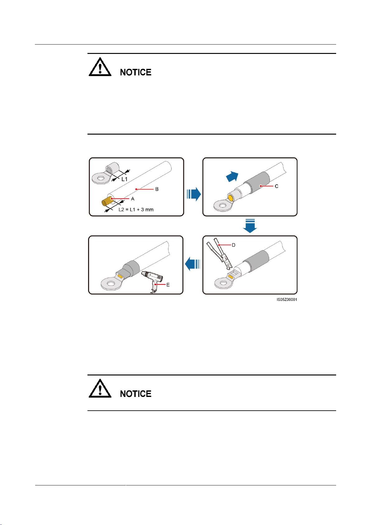
Step 1 Crimp the OT terminal.
Page 46
SUN2000-(2KTL-5KTL)-L0
User Manual
5 Electrical Connections
Issue 01 (2018-08-30)
Copyright © Huawei Technologies Co., Ltd.
40
(A) Core wire
(B) Insulation layer
(C) Heat shrink tubing
(D) Hydraulic pliers
(E) Heat gun
Pay attention not to damage the core wire when stripping a cable.
The cavity formed after the conductor crimp strip of the OT terminal is crimped must wrap
the core wires completely. The core wires must contact the OT terminal closely.
Wrap the wire crimping area with heat shrink tubing or PVC insulation tape. The
following figure uses heat shrink tubing as an example.
When using the heat gun, protect devices from being scorched.
Figure 5-2 Crimping an OT terminal
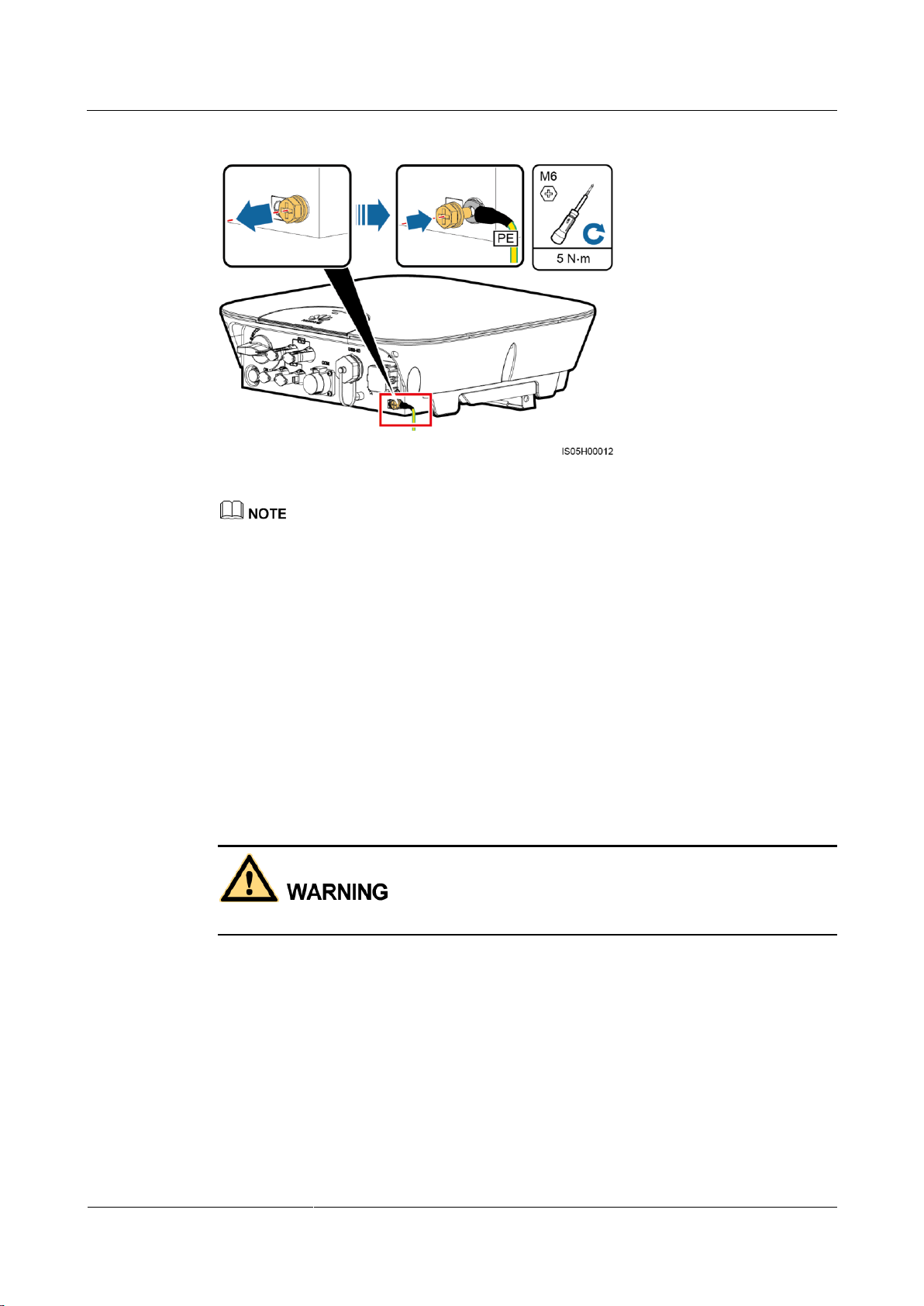
Step 2 Connect the PE cable.
Ensure that the PE cable is connected securely.
Page 47
SUN2000-(2KTL-5KTL)-L0
User Manual
5 Electrical Connections
Issue 01 (2018-08-30)
Copyright © Huawei Technologies Co., Ltd.
41
Figure 5-3 Connecting a PE cable
The PE point at the AC output port is used only as a PE equipotential point, and cannot substitute for
the PE point on the enclosure.
To enhance the corrosion resistance of a ground terminal, apply silica gel or paint around the
terminal after connecting the PE cable.
----End
5.3 Installing the AC Output Power Cable
Prerequisites
An AC switch must be installed on the AC side of the SUN2000 to ensure that the SUN2000
can be safely disconnected from the power grid.
Do not connect any load between the SUN2000 and the AC switch.
Context
The SUN2000 can detect the grounding. This function is used to detect whether the SUN2000
is properly grounded before starting it, or to detect whether the PE cable is disconnected when
the SUN2000 is working. This function is available only under limited conditions. To ensure
the safe operation of the SUN2000, properly ground the SUN2000 in strict accordance with
the connection requirements for PE cables. For certain types of power grids, if an isolation
transformer connects to the output side of the SUN2000, you need to set Grounding
inspection to Disable after checking that the SUN2000 is properly grounded. Then the
SUN2000 can start normally. If you are not sure whether the SUN2000 connects to such a
power grid, confirm it with your supplier or Huawei technical support.
Page 48
SUN2000-(2KTL-5KTL)-L0
User Manual
5 Electrical Connections
Issue 01 (2018-08-30)
Copyright © Huawei Technologies Co., Ltd.
42
Procedure
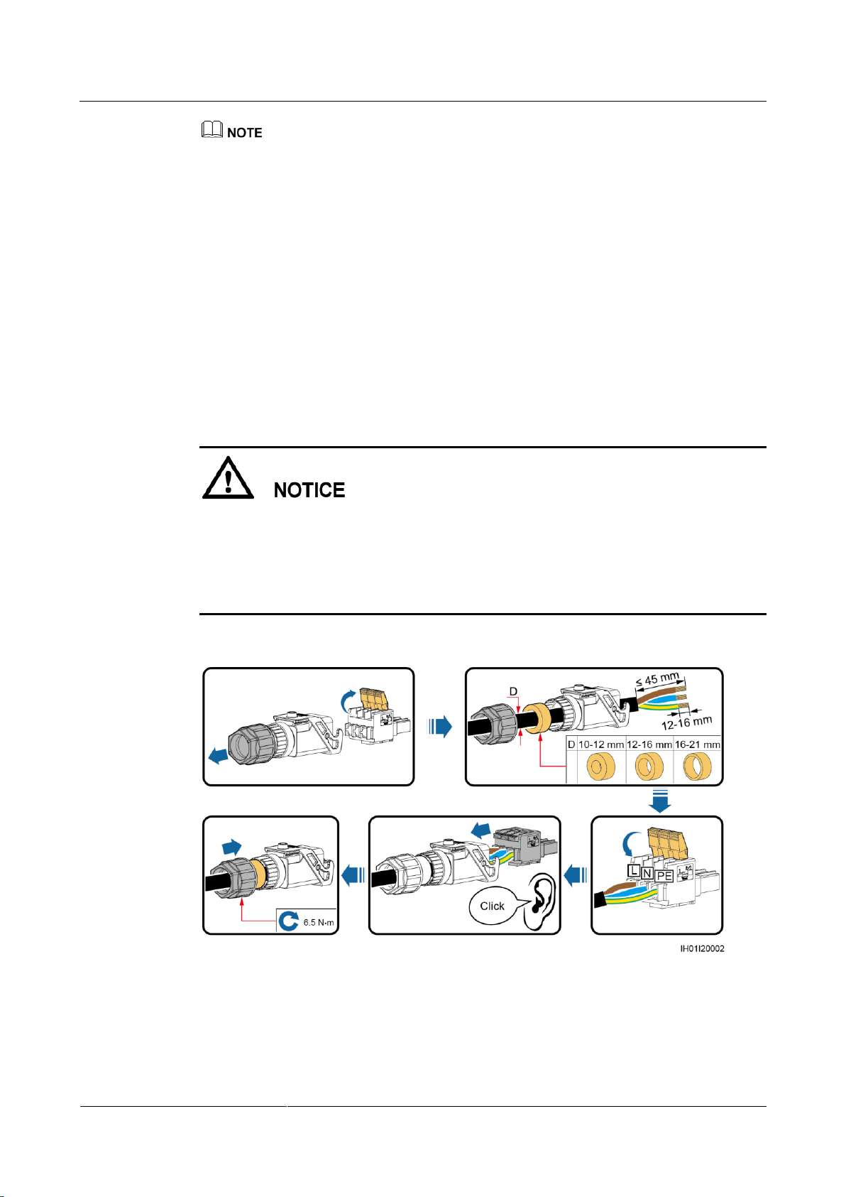
Step 1 Connect the AC output power cable to the AC connector.
According to IEC62109, to ensure the safe operation of the SUN2000 in the case of PE cable
damage or disconnection, connect the SUN2000 PE cable according to the requirements described in
5.2 Installing the PE Cable and ensure that the SUN2000 PE cable meets at least one of the
following requirements before disabling the grounding detection function.
The SUN2000 PE cable is a copper cable with a cross-sectional area of at least 10 mm2.
Use two cables that have the same diameter as the AC output power cable to ground the PE terminal
on the AC connector and the ground screw on the enclosure respectively (see 5.2 Installing the PE
Cable and 5.3 Installing the AC Output Power Cable for details).
Certain countries require an additional PE cable for the SUN2000. In this case, use two cables that
have the same diameter as the AC output power cable to ground the PE terminal on the AC
connector and the ground screw on the enclosure respectively (see 5.2 Installing the PE Cable and
5.3 Installing the AC Output Power Cable for details).
Ensure that the cable jacket is inside the connector.
Ensure that the exposed core wire is totally inserted into the cable hole.
Ensure that AC terminations provide firm and solid electrical connections. Failing to do so
may cause SUN2000 malfunction and damage to its AC connectors.
Ensure that the cable is not twisted.
Figure 5-4 Assembling an AC connector (three-core wire)
Page 49
SUN2000-(2KTL-5KTL)-L0
User Manual
5 Electrical Connections
Issue 01 (2018-08-30)
Copyright © Huawei Technologies Co., Ltd.
43
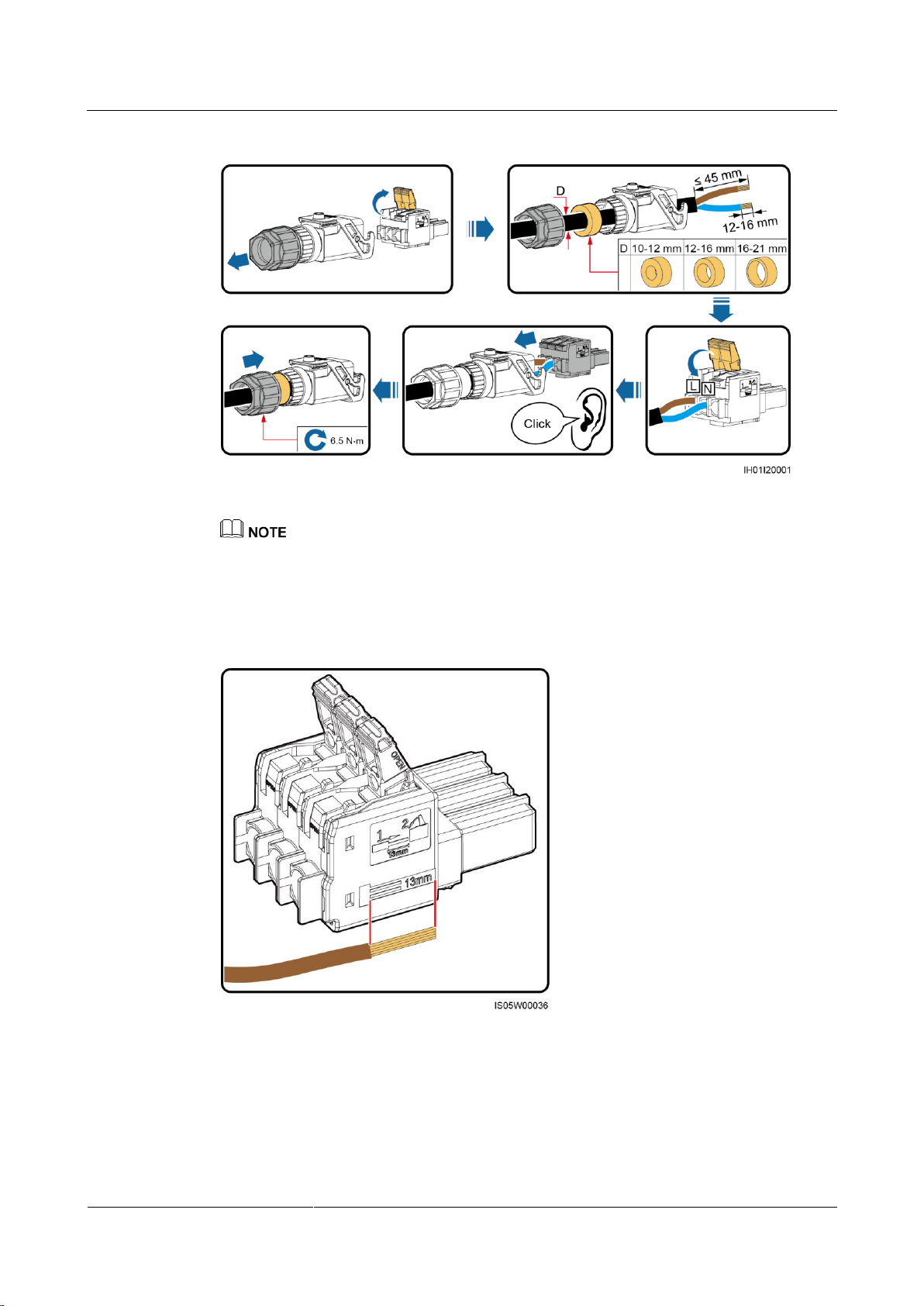
Figure 5-5 Assembling an AC connector (two-core wire)
The cable colors shown in figures are for reference only. Select an appropriate cable according to the
local standards.
For the core wire installation method and stripped length, see the instructions on the side of the plug
insert.
Figure 5-6 Stripped length
Step 2 Connect the AC connector to the AC output port.
Page 50
SUN2000-(2KTL-5KTL)-L0
User Manual
5 Electrical Connections
Issue 01 (2018-08-30)
Copyright © Huawei Technologies Co., Ltd.
44
Ensure that the AC connector is connected securely.
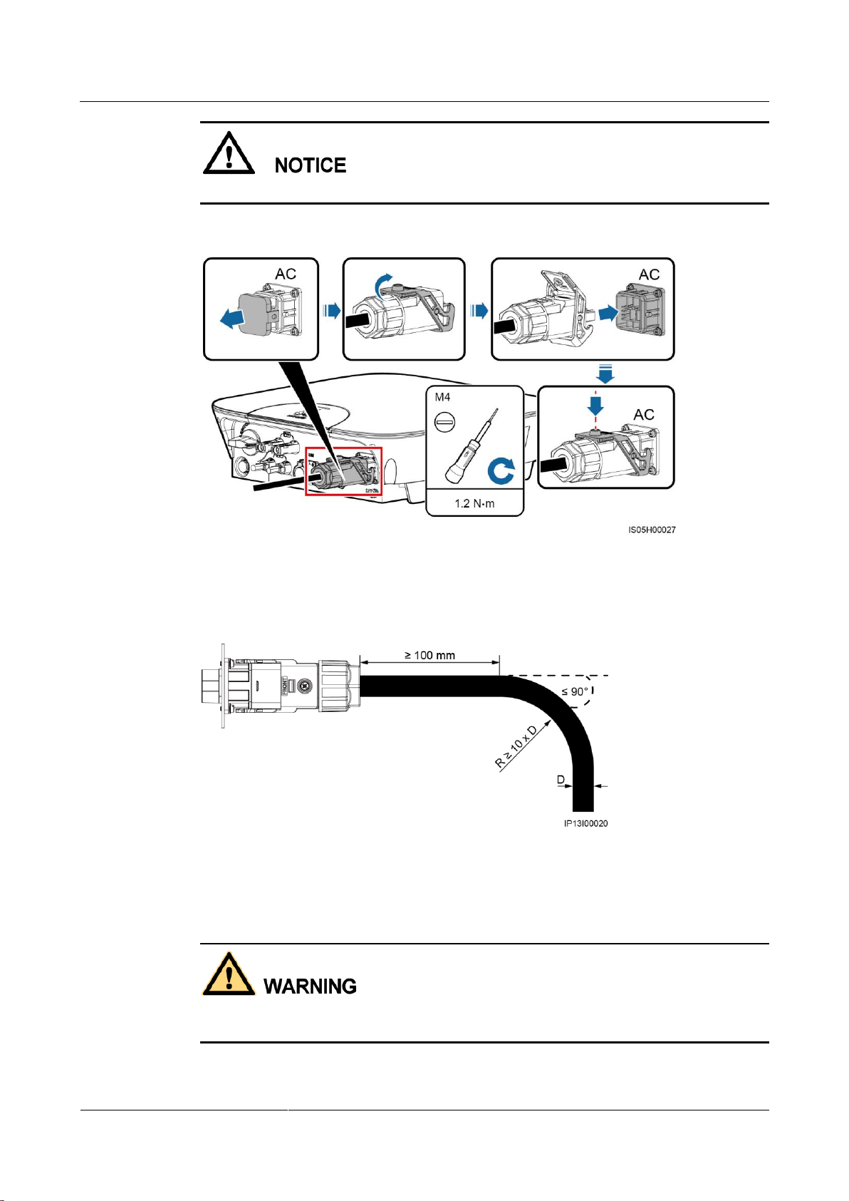
Figure 5-7 Securing an AC connector
Step 3 Check the route of the AC output power cable.
Figure 5-8 Cable route
----End
Follow-up Procedure
Before removing the AC connector, ensure that the DC switch at the bottom of the SUN2000
and all the switches connecting to the SUN2000 are OFF.
To remove the AC connector from the SUN2000, perform the operations in reverse order.
Page 51
SUN2000-(2KTL-5KTL)-L0
User Manual
5 Electrical Connections
Issue 01 (2018-08-30)
Copyright © Huawei Technologies Co., Ltd.
45
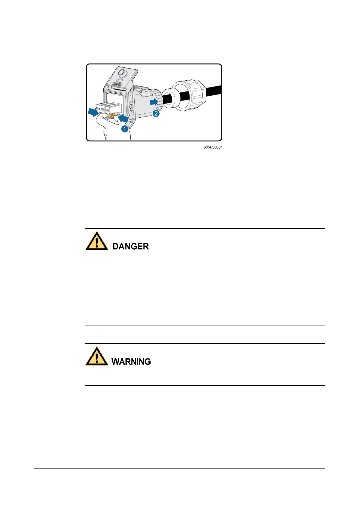
Figure 5-9 Removing a plug insert
5.4 Installing the DC Input Power Cable
Prerequisites
Before connecting the DC input power cable, ensure that the DC voltage is within the safe
range (lower than 60 V DC) and that the DC switch on the SUN2000 is OFF. Failing to do
so may result in electric shocks.
When the SUN2000 is operating, it is not allowed to work on DC circuit, such as
connecting or disconnecting a PV string or a PV module in a PV string. Failing to do so
may cause electric shocks.
If no PV string connects to the DC input terminals, do not remove the watertight cap from
the DC input terminals. Otherwise, the SUN2000 will not comply with its Ingress
Protection Rating.
Ensure that the following conditions are met. Otherwise, the SUN2000 will be damaged, or
even become a fire hazard.
Page 52
SUN2000-(2KTL-5KTL)-L0
User Manual
5 Electrical Connections
Issue 01 (2018-08-30)
Copyright © Huawei Technologies Co., Ltd.
46
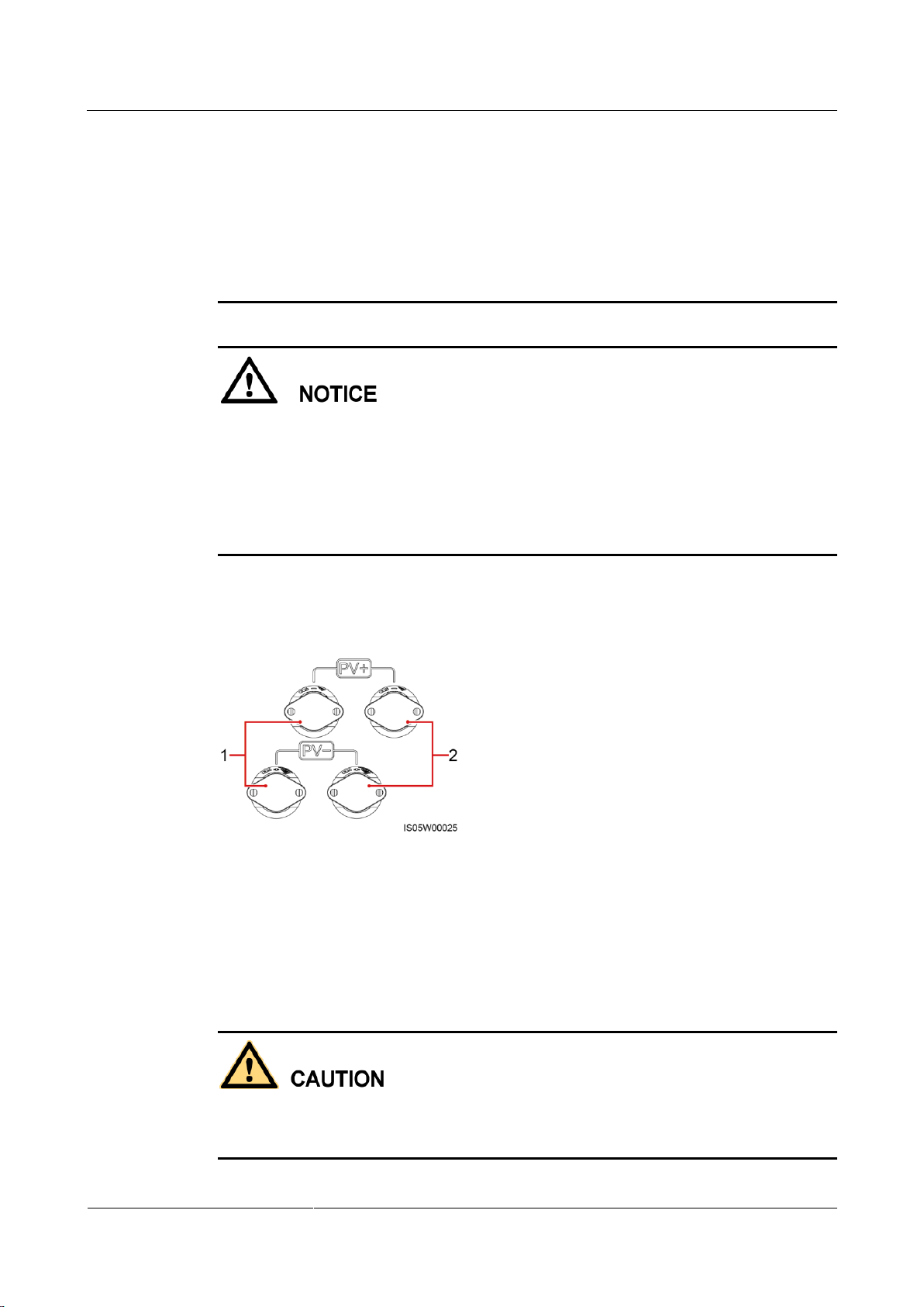
(1) The first set of DC input terminals
(2) The second set of DC input terminals
The open-circuit voltage of each PV string is always lower than or equal to 600 V DC.
The positive and negative terminals of a PV string connect to corresponding positive and
negative DC input terminals of the SUN2000.
If polarity of the DC input power cable is reversed and the DC switch is ON, do not turn
off the DC switch immediately or unplug positive and negative connectors. Wait until the
solar irradiance declines at night and the PV string current reduces to below 0.5 A, and
then turn off the DC switch and remove the positive and negative connectors. Correct the
string polarity before reconnecting the string to the SUN2000.
The PV terminal of the inverter supports only the PV string input and cannot be connected
to other power supplies. Since the output of the PV string connected to the SUN2000
cannot be grounded, ensure that the PV module output is well insulated to ground.
During the installation of PV strings and SUN2000, the positive or negative terminals of
PV strings may be grounded if power cables are not properly installed or routed. In this
case, an AC or DC short circuit may occur and damage the SUN2000. This damage is not
covered under any warranty.
Context
Procedure
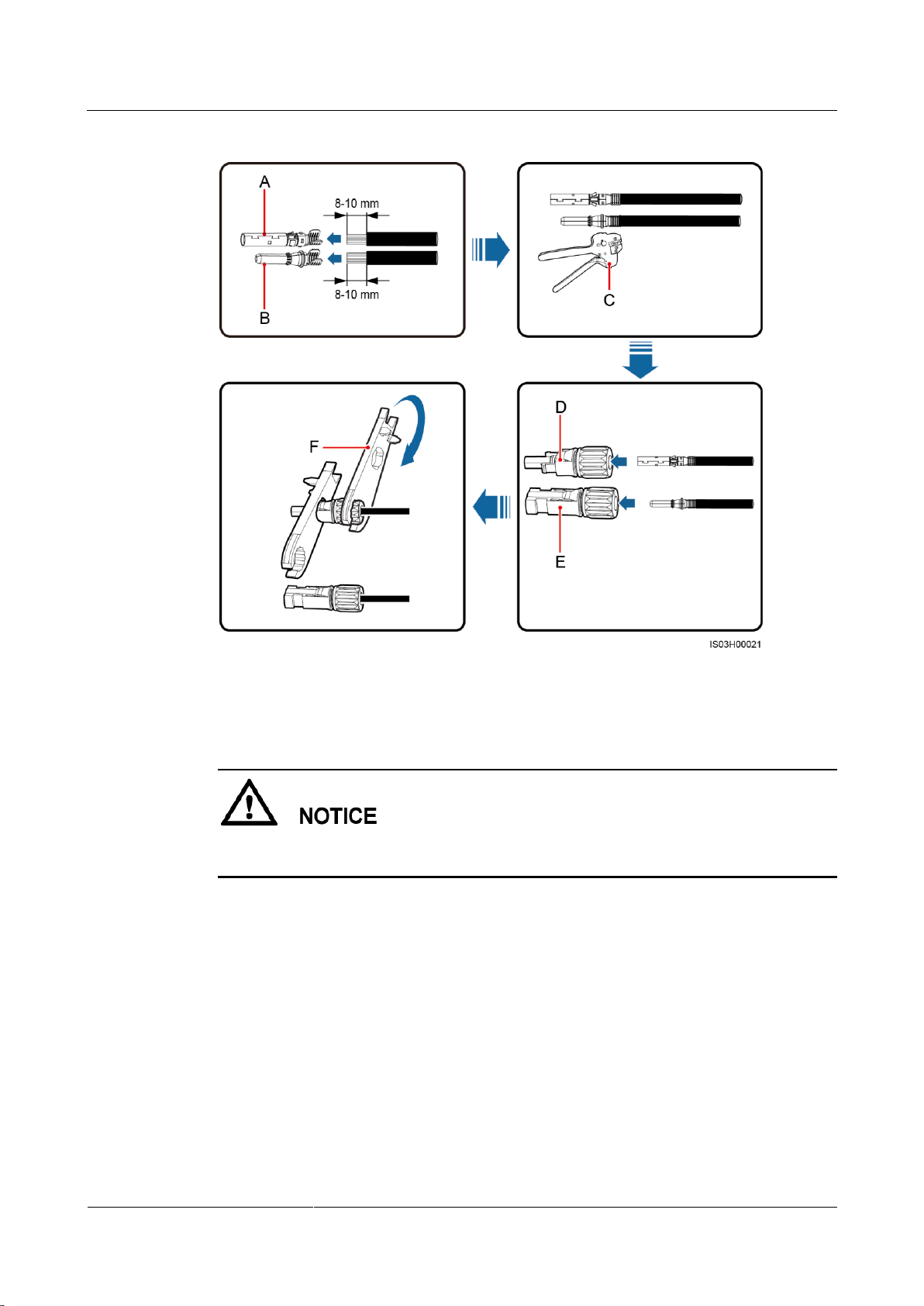
Step 1 Assemble the black positive and negative connectors.
Figure 5-10 DC input terminals
Use the positive and negative metal contacts and DC connectors supplied with the SUN2000.
Using incompatible positive and negative metal contacts and DC connectors may result in
serious consequences. The caused device damage is not covered under any warranty.
Page 53
SUN2000-(2KTL-5KTL)-L0
User Manual
5 Electrical Connections
Issue 01 (2018-08-30)
Copyright © Huawei Technologies Co., Ltd.
47
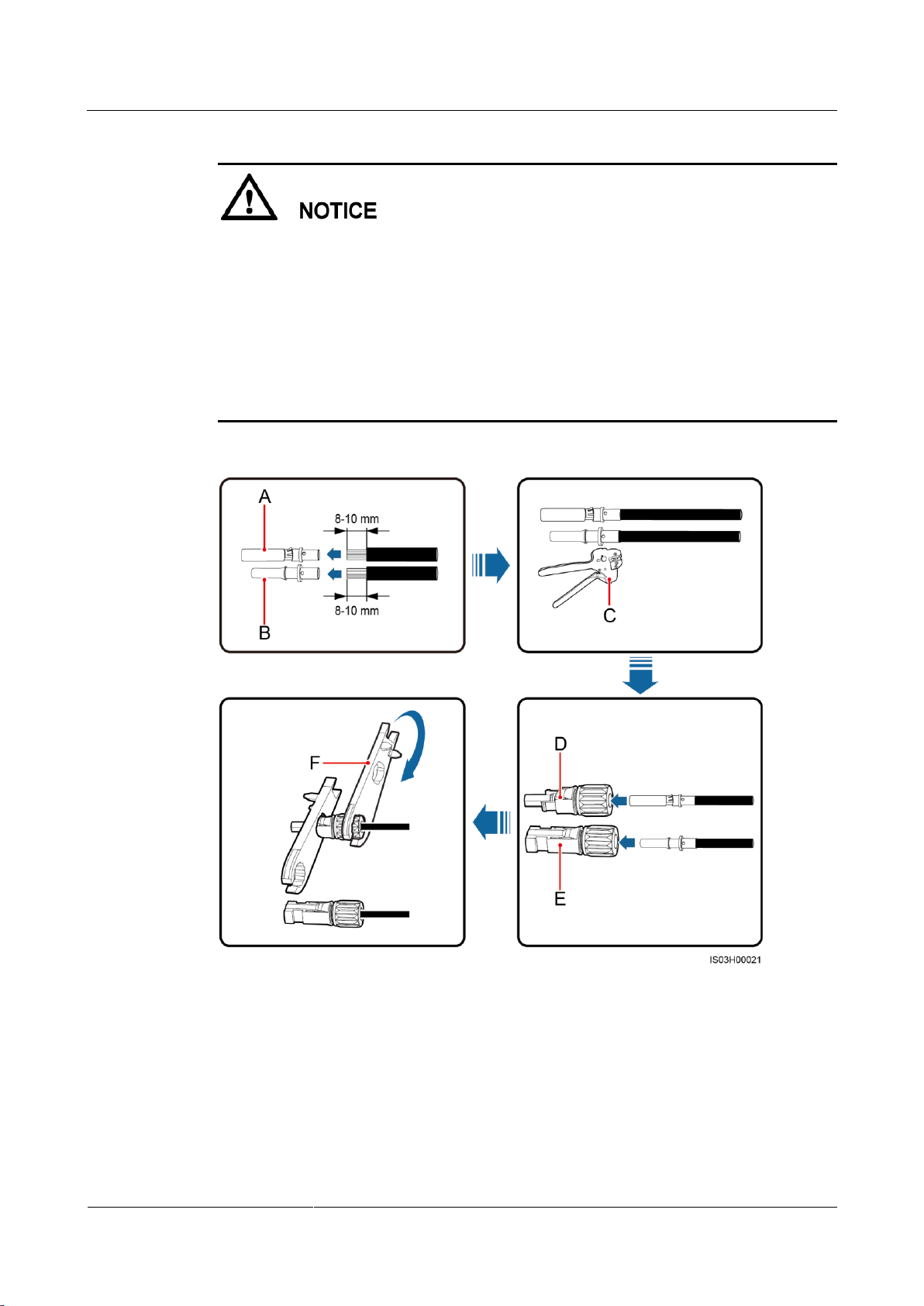
(A) Positive metal contact
(B) Negative metal contact
(C) H4TC0001 crimping tool
(D) Positive connector
(E) Negative connector
(F) H4TW0001 open-end wrench
Cables with high rigidity, such as armored cables, are not recommended as DC input
power cables, because poor contact may be caused by the bending of the cables.
Before assembling DC input connectors, label the cable polarities correctly to ensure
correct cable connections.
After crimping the positive and negative metal contacts, pull the DC input power cables
back to check that they are connected securely.
Insert the crimped metal contacts of the positive and negative power cables into the
corresponding positive and negative connectors. Then pull back the DC input power cables
to check that they are connected securely.
Figure 5-11 Assembling DC connectors (using metal cold forming contacts)
Page 54
SUN2000-(2KTL-5KTL)-L0
User Manual
5 Electrical Connections
Issue 01 (2018-08-30)
Copyright © Huawei Technologies Co., Ltd.
48
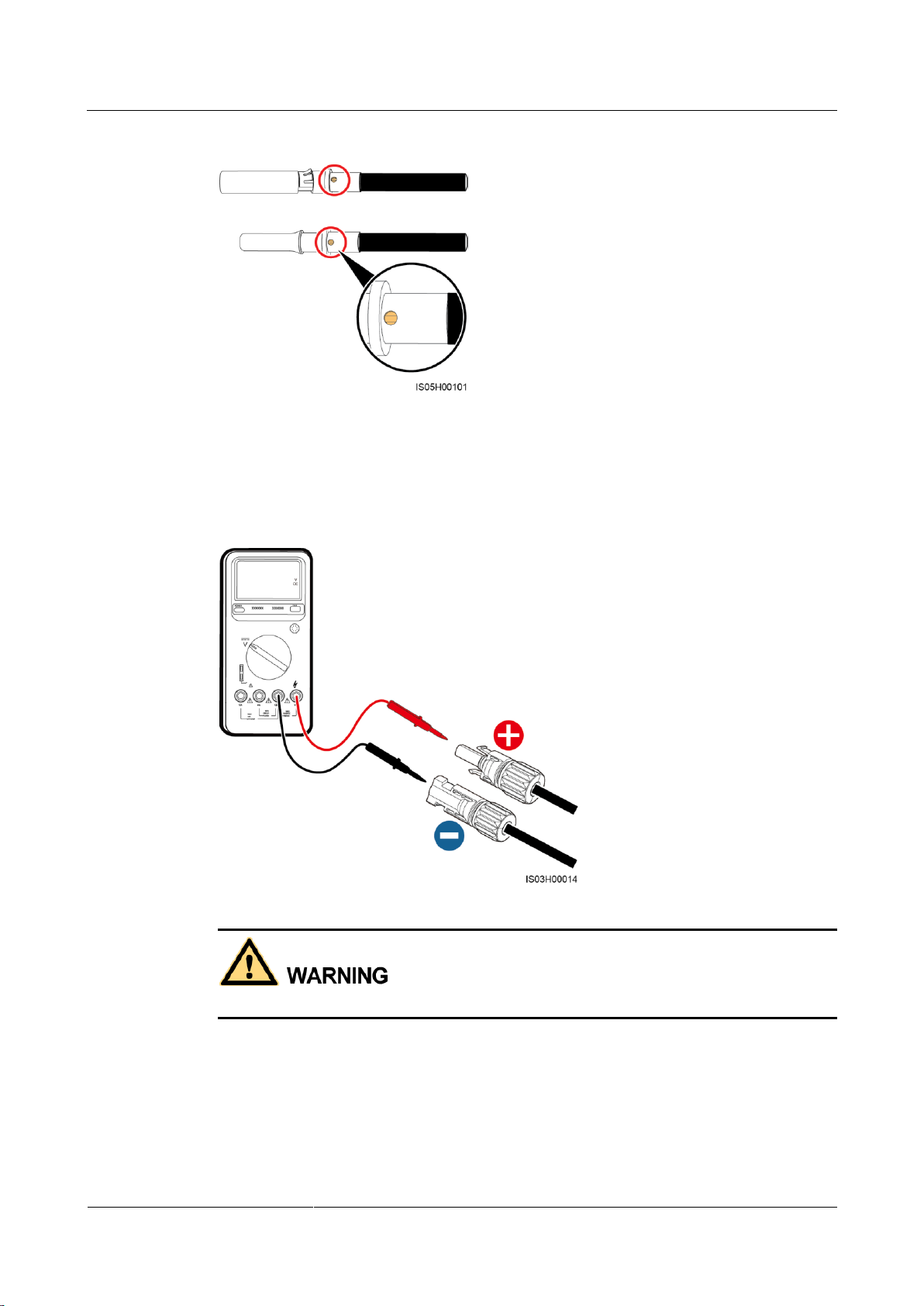
Figure 5-12 Assembling DC connectors (using metal stamping forming contacts)
(A) Positive metal contact
(B) Negative metal contact
(C) H4TC0002 crimping tool
(D) Positive connector
(E) Negative connector
(F) H4TW0001 open-end wrench
Ensure that the core wires can be seen through the hole on the terminal both before and after
the positive and negative metal terminals are crimped.
Page 55
SUN2000-(2KTL-5KTL)-L0
User Manual
5 Electrical Connections
Issue 01 (2018-08-30)
Copyright © Huawei Technologies Co., Ltd.
49
Figure 5-13 Observing core wires through the hole on the terminal
Step 2 Ensure that the DC input voltage of each PV string is within the specified range of the
SUN2000 using a multimeter and check that the polarities of DC input power cables are
correct.
Figure 5-14 Measuring the DC input voltage
Before performing Step 3, ensure that the DC switch is OFF.
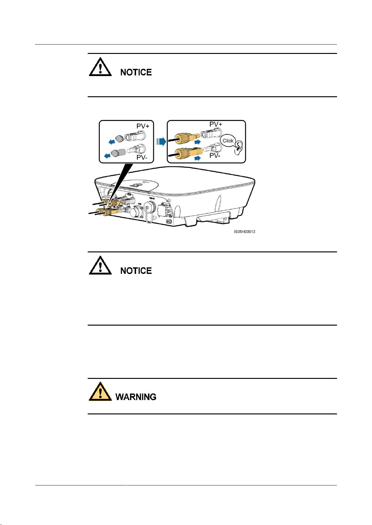
Step 3 Insert the positive and negative connectors into corresponding DC input terminals on the
SUN2000.
Page 56
SUN2000-(2KTL-5KTL)-L0
User Manual
5 Electrical Connections
Issue 01 (2018-08-30)
Copyright © Huawei Technologies Co., Ltd.
50
After the positive and negative connectors snap into place, pull the DC input power cables
back to check that they are connected securely.
Figure 5-15 Connecting DC input power cables
If polarity of the DC input power cable is reversed and the DC switch is ON, do not turn off
the DC switch immediately or unplug positive and negative connectors. The device may be
damaged if you do not follow the instruction. This damage is not covered under any warranty.
Wait until the solar irradiance declines at night and the PV string current reduces to below 0.5
A, and then turn off the DC switch and remove the positive and negative connectors. Correct
the string polarity before reconnecting the string to the SUN2000.
----End
Follow-up Procedure
Before removing the positive and negative connectors, ensure that the DC switch is OFF.
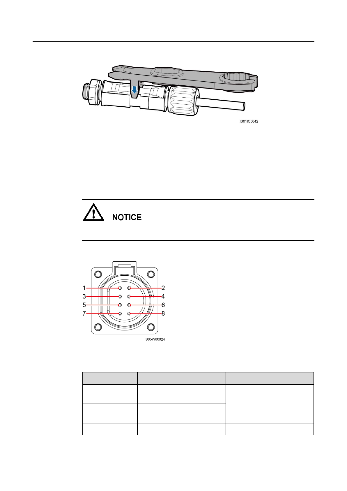
To remove the positive and negative connectors from the SUN2000, insert an open-end
wrench into the notch and press the wrench with an appropriate force.
Page 57
SUN2000-(2KTL-5KTL)-L0
User Manual
5 Electrical Connections
Issue 01 (2018-08-30)
Copyright © Huawei Technologies Co., Ltd.
51
Figure 5-16 Removing a DC connector
No.
Label
Definition
Description
1
485B1
RS485B, RS485 differential
signal–
Connects to the RS485 signal
port on the power collector.
2
485A1
RS485A, RS485 differential
signal+
3
485B2
RS485B, RS485 differential
Reserved, can connect to the
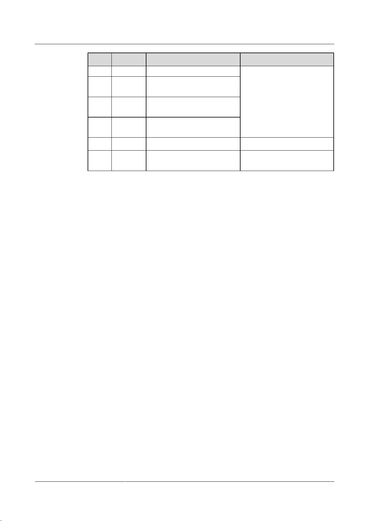
5.5 Installing the Signal Cable
Context
When laying out signal cables, separate them from power cables to avoid strong signal
interference sources.
Figure 5-17 COM port
Table 5-3 COM port pin definitions
Page 58
SUN2000-(2KTL-5KTL)-L0
User Manual
5 Electrical Connections
Issue 01 (2018-08-30)
Copyright © Huawei Technologies Co., Ltd.
52
No.
Label
Definition
Description
signal–
RS485 signal port on
SmartPSB2000L Smart PV
Safety Box.
4
485A2
RS485A, RS485 differential
signal+
5
12V–
Negative polarity of the 12 V
power port
6
12 V+
Positive polarity of the 12 V
power port
7
N/A
N/A
N/A
8
PE
Port for grounding the shield
layer
Connects to the shield layer of
the cable.
Procedure
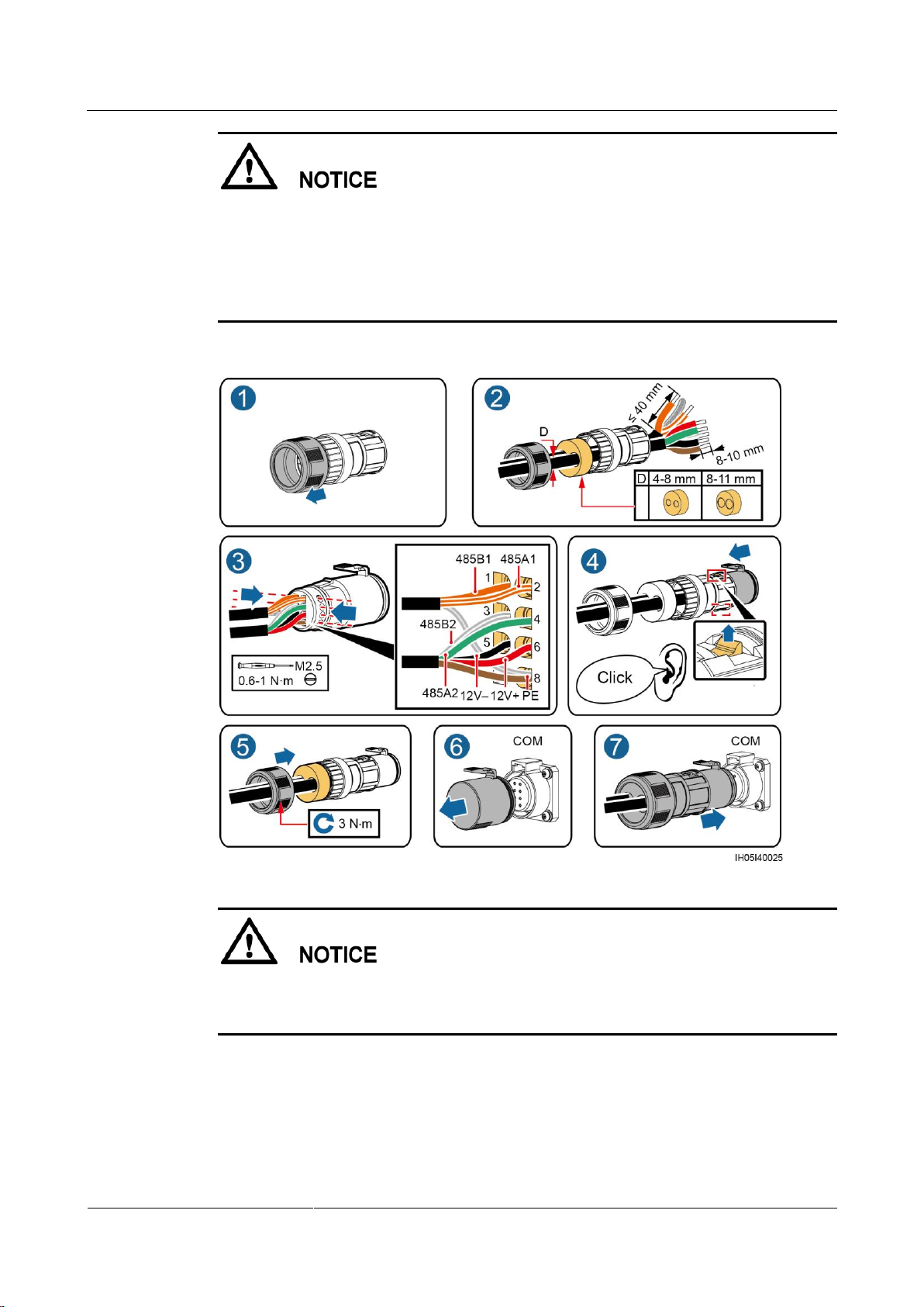
Step 1 Connect signal cables to appropriate signal connectors.
Page 59
SUN2000-(2KTL-5KTL)-L0
User Manual
5 Electrical Connections
Issue 01 (2018-08-30)
Copyright © Huawei Technologies Co., Ltd.
53
Ensure that the cable jacket is inside the connector.
Ensure that the exposed core wire is totally inserted into the cable hole.
Ensure that the signal cables are connected securely.
Ensure that no cable is twisted.
If two signal cables are required, ensure that they have the same outer diameter.
Figure 5-18 Assembling a signal connector
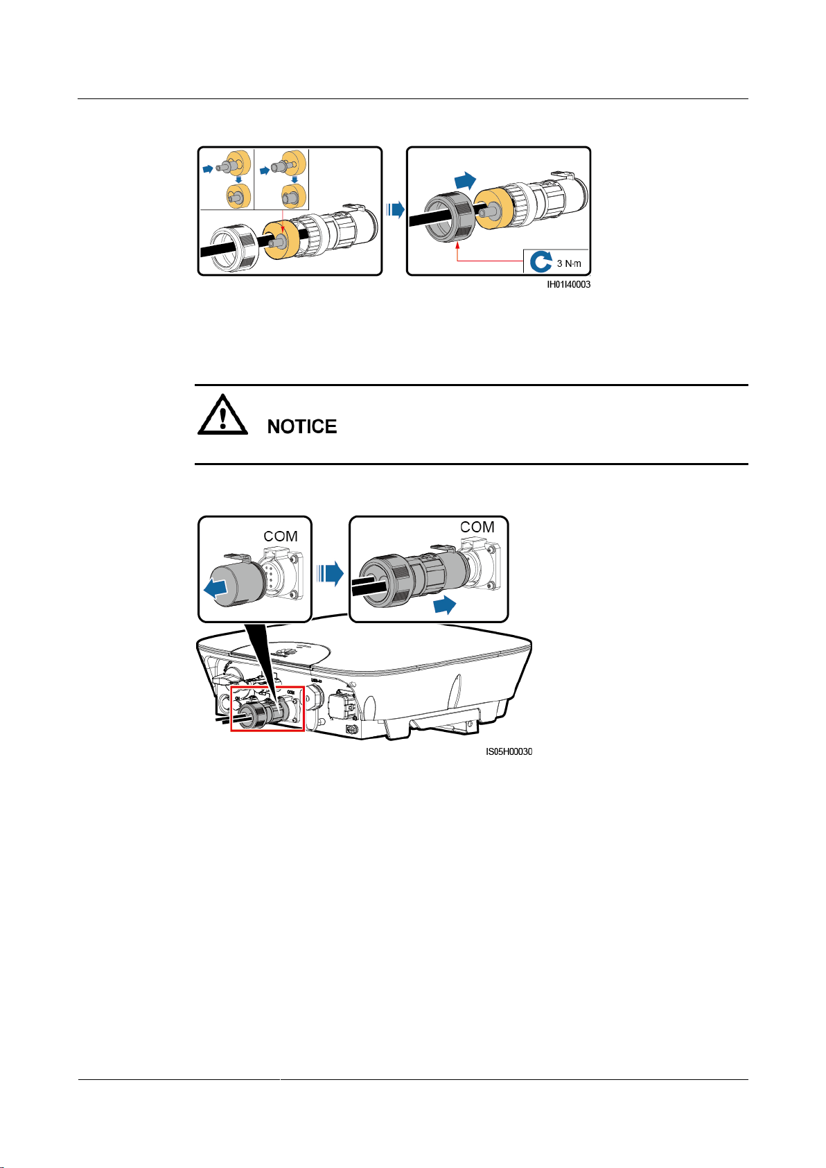
This document takes the connection of two signal lines as an example. If only one signal cable
needs to be connected, block the unused cable hole on the seal using a cap and tighten the
cable gland.
Page 60
SUN2000-(2KTL-5KTL)-L0
User Manual
5 Electrical Connections
Issue 01 (2018-08-30)
Copyright © Huawei Technologies Co., Ltd.
54
Figure 5-19 Installing a cap
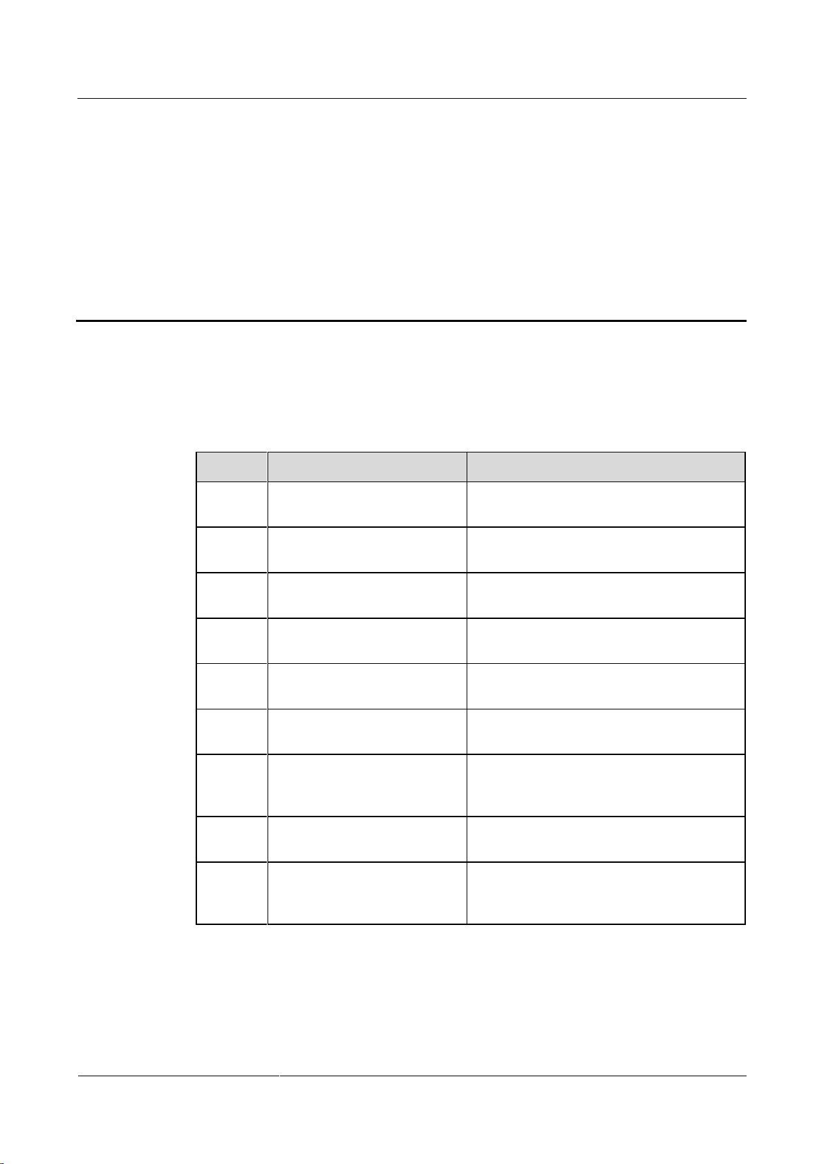
Step 2 Connect the signal connector to the corresponding port.
Ensure that the signal connector is connected securely.
Figure 5-20 Securing a plug
----End
Page 61
SUN2000-(2KTL-5KTL)-L0
User Manual
6 System Commissioning
Issue 01 (2018-08-30)
Copyright © Huawei Technologies Co., Ltd.
55
6 System Commissioning
No.
Check Item
Acceptance Criteria
1
SUN2000 installation
The SUN2000 is installed correctly,
securely, and reliably.
2
Installation of the WiFi
antenna or 4G module
The WiFi antenna or 4G module is installed
correctly, securely, and reliably.
3
Cable layout
Cables are routed properly as required by the
customer.
4
Cable tie
Cable ties are secured evenly and no burr
exists.
5
Grounding
The ground cable is connected correctly,
securely, and reliably.
6
DC switch
The DC switch and all the switches
connecting to the SUN2000 are OFF.
7
Cable connections
The AC output power cable, DC input power
cable, and signal cable are connected
correctly, securely, and reliably.
8
Unused terminals and ports
Unused terminals and ports are locked by
watertight caps.
9
Installation environment
The installation space is proper, and the
installation environment is clean and tidy,
without foreign matter.
6.1 Checking Before Power-On
Table 6-1 Installation checklist
Page 62
SUN2000-(2KTL-5KTL)-L0
User Manual
6 System Commissioning
Issue 01 (2018-08-30)
Copyright © Huawei Technologies Co., Ltd.
56
6.2 Powering On the System
Type
Status
Meaning
Running
indication
LED 1
LED 2
N/A
Steady green
Steady green
The SUN2000 is exporting
power to the power grid.
Blinking green
at long intervals
(on for 1s and
then off for 1s)
Off
The DC is on and the AC is
off.
Off
Blinking green at
long intervals (on
for 1s and then
off for 1s)
The DC is off and the AC is
on.
Blinking green
at long intervals
(on for 1s and
then off for 1s)
Blinking green at
long intervals (on
for 1s and then
off for 1s)
Both the DC and AC are on,
and the SUN2000 is not
exporting power to the power
grid.
Prerequisites
Before turning on the AC switch between the SUN2000 and the power grid, check that the AC
voltage on the power grid side of the AC switch is within the specified range.
If the DC is on and the AC is off, the SUN2000 reports a Grid Failure alarm. The SUN2000
starts normally only after the fault is rectified.
Procedure
Step 1 Turn on the AC switch between the SUN2000 and the power grid.
Step 2 Turn on the DC switch between the PV string and the SUN2000 if there is any.
Step 3 Turn on the DC switch at the bottom of the SUN2000.
Step 4 Perform quick settings on the FusionHome app.
Step 5 (Optional) Measure the temperatures at the joints between the DC terminals and the
connectors using a point-test thermometer.
Under normal operation conditions of the SUN2000, the temperature rise at DC terminals should remain
below 30°C at all time.
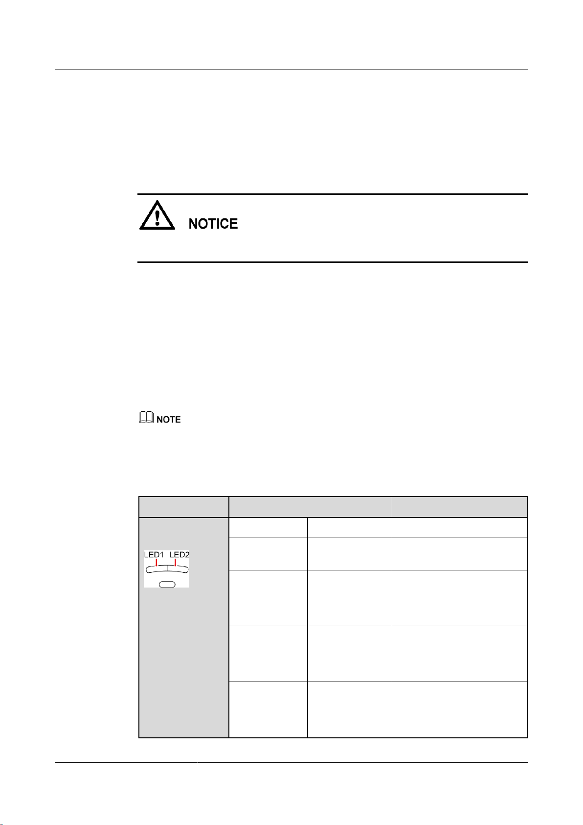
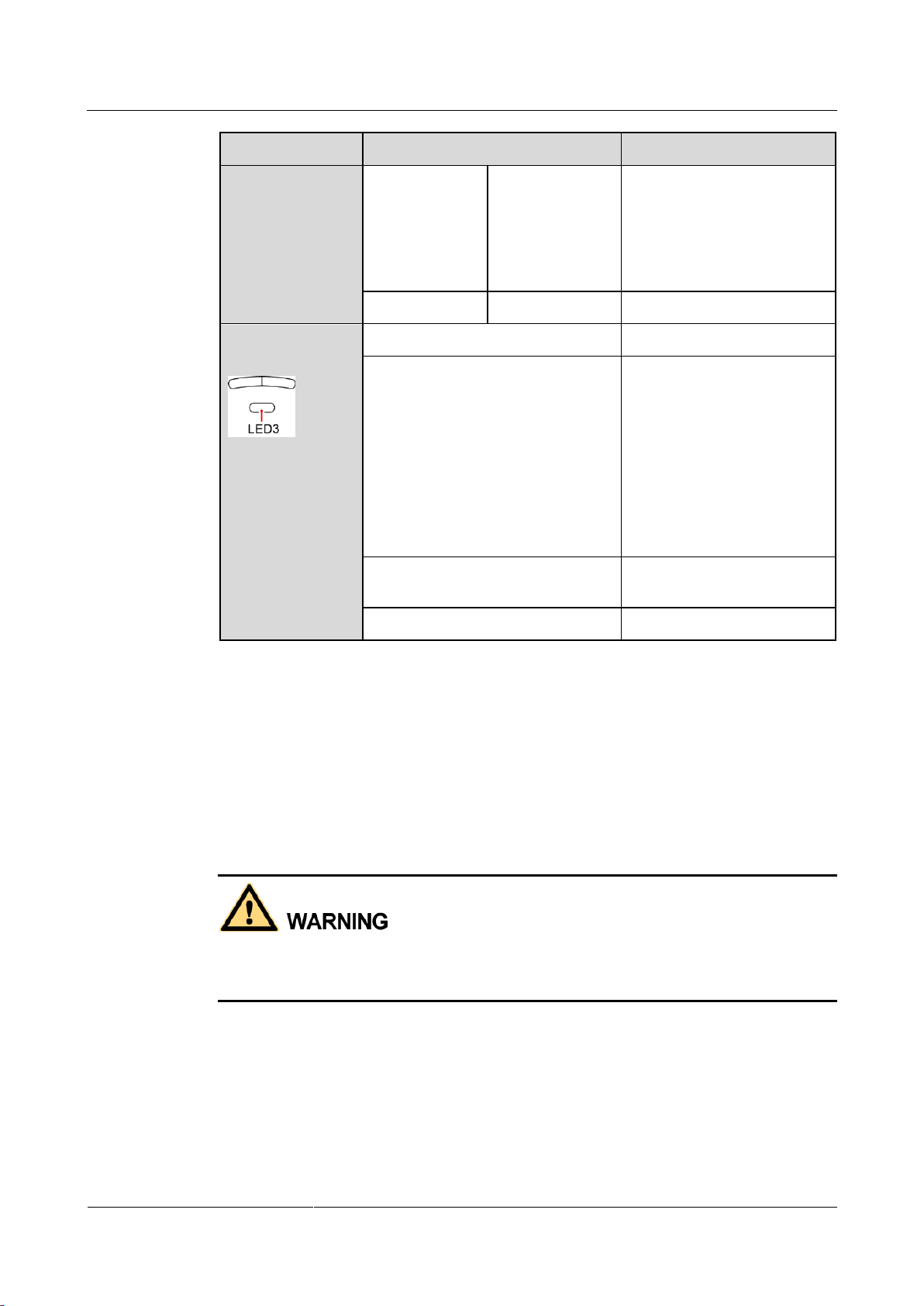
Step 6 Observe the LEDs to check the SUN2000 operating status.
Table 6-2 LED description
Page 63
SUN2000-(2KTL-5KTL)-L0
User Manual
6 System Commissioning
Issue 01 (2018-08-30)
Copyright © Huawei Technologies Co., Ltd.
57
Type
Status
Meaning
Off
Off
Both the DC and AC are off,
or the SUN2000 is in low
power consumption mode
which means that the
monitoring system of the
SUN2000 hibernates.
Steady red
Steady red
The SUN2000 is faulty
Communication
indication
LED 3
N/A
Blinking green at short intervals (on
for 0.2s and then off for 0.2s)
Communicating
(Communicating refers to that
the communication with the
upper-level management unit
is in progress. However, if a
mobile phone accesses the
SUN2000, the LED indicates
the "mobile phone access
status: blinking green at long
intervals" first.)
Blinking green at long intervals (on
for 1s and then off for 1s)
The mobile phone has
connected to the SUN2000.
Off
No communication
----End
6.3 Powering Off the System
Context
After the SUN2000 powers off, the remaining electricity and heat may still cause electric
shocks and body burns. Therefore, put on protective gloves and begin servicing the SUN2000
five minutes after the power-off.
Procedure
Step 1 Send a shutdown command from the FusionHome app.
Step 2 Turn off the AC switch between the SUN2000 and the power grid.
Step 3 Turn off the DC switch at the bottom of the SUN2000.
Page 64

SUN2000-(2KTL-5KTL)-L0
User Manual
6 System Commissioning
Issue 01 (2018-08-30)
Copyright © Huawei Technologies Co., Ltd.
58
Step 4 Turn off the DC switch between the PV string and the SUN2000 if there is any.
----End
Page 65
SUN2000-(2KTL-5KTL)-L0
User Manual
7 System Maintenance
Issue 01 (2018-08-30)
Copyright © Huawei Technologies Co., Ltd.
59
7.1 Routine Maintenance
Check Item
Acceptance Criteria
Maintenance
Interval
System
cleanliness
The heat sinks are free from obstacles or
dust.
Once every 6 to 12
months
System running
status
The SUN2000 is not damaged or
deformed.
The SUN2000 operates with no
abnormal sound.
All SUN2000 parameters are correctly
set. Perform this check when the
SUN2000 is running.
Once every 6 months
Electrical
connections
Cables are securely connected.
Cables are intact, and in particular, the
parts touching the metallic surface are
not scratched.
Unused DC input terminals, COM ports,
ANT ports, and USB-4G ports are
locked by watertight caps.
The first maintenance is
half a year after the
initial commissioning.
From then on, perform
the maintenance once
every 6 to 12 months.
To ensure that the SUN2000 can operate properly for a long term, you are advised to perform
routine maintenance on it as described in this chapter.
7 System Maintenance
Before cleaning the system, connecting cables, and maintaining the grounding reliability,
power off the system (see 6.3 Powering Off the System for details).
Table 7-1 Maintenance list
Page 66
SUN2000-(2KTL-5KTL)-L0
User Manual
7 System Maintenance
Issue 01 (2018-08-30)
Copyright © Huawei Technologies Co., Ltd.
60
Check Item
Acceptance Criteria
Maintenance
Interval
Grounding
reliability
Ground cables are securely connected.
The first maintenance is
half a year after the
initial commissioning.
From then on, perform
the maintenance once
every 6 to 12 months.
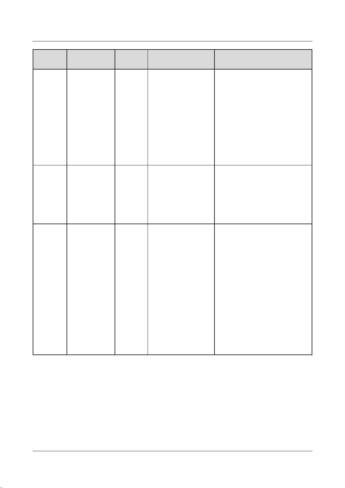
Alarm ID
Alarm Name
Alarm
Severity
Possible Cause
Suggestion
2001
High String
Input Voltage
Major
The PV array is
incorrectly configured.
Excessive PV modules
are connected in series
to the PV string, and
therefore the
open-circuit voltage
exceeds the maximum
inverter input voltage.
Reduce the number of PV modules
connected in series to the PV string
until the PV string open-circuit
voltage is less than or equal to the
maximum inverter input voltage.
After the PV array is correctly
configured, the inverter alarm
disappears.
The following is the mapping
between PV strings and alarm cause
IDs:
Cause ID = 1: string 1
Cause ID = 2: string 2
7.2 Troubleshooting
Alarm severities are defined as follows:
Major: The SUN2000 enters Shutdown mode and disconnects from the power grid to
stop generating power after a fault occurs.
Minor: Some components are faulty but the SUN2000 can still connect to the power grid
and generate power.
Warning: The SUN2000 output power decreases due to external factors.
Table 7-2 Common alarms and troubleshooting measures
Page 67
SUN2000-(2KTL-5KTL)-L0
User Manual
7 System Maintenance
Issue 01 (2018-08-30)
Copyright © Huawei Technologies Co., Ltd.
61
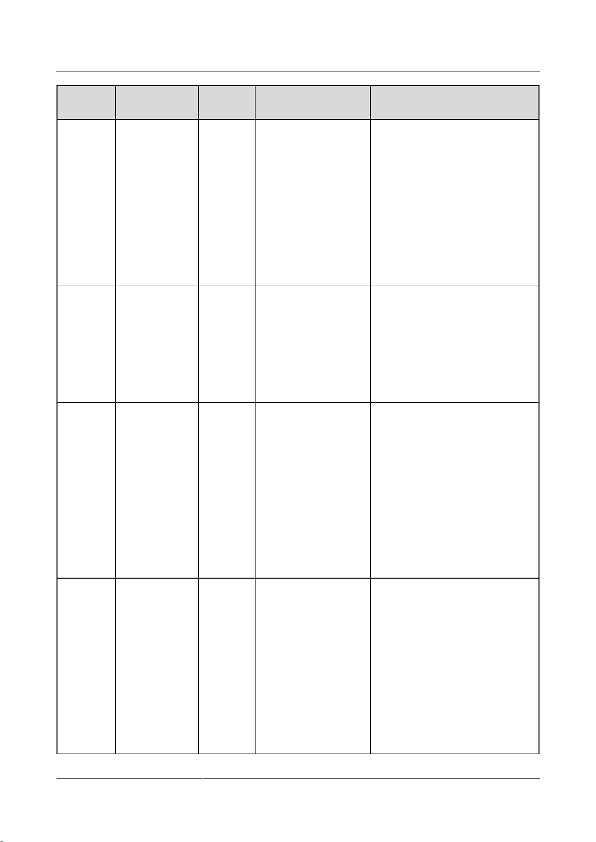
Alarm ID
Alarm Name
Alarm
Severity
Possible Cause
Suggestion
2011
String Reversed
Major
The PV string is
reversely connected.
Check whether the PV string is
reversely connected to the SUN2000.
If yes, wait until the solar irradiance
declines at night and the PV string
current reduces to below 0.5 A.
Then, turn off the DC switch and
correct the PV string polarity.
The following is the mapping
between PV strings and alarm cause
IDs:
Cause ID = 1: string 1
Cause ID = 2: string 2
2032
Grid Failure
Major
Cause ID = 1
The power grid
experiences an
outage.
The AC circuit is
disconnected or AC
switch is off.
1. Check the AC voltage.
2. Check that the AC power cable is
connected and that the AC switch
is ON.
2033
Grid
Undervoltage
Major
Cause ID = 1
The grid voltage is
below the lower
threshold or the low
voltage duration has
lasted for more than the
value specified by
LVRT.
1. If the alarm occurs accidentally,
the power grid may be abnormal
temporarily. The SUN2000
automatically recovers after
detecting that the power grid
becomes normal.
2. If the alarm occurs frequently,
check whether the grid voltage is
within the acceptable range. If no,
contact the local power operator.
If yes, modify the power grid
undervoltage protection
thresholds with the consent of the
local power operator.
3. If the fault persists for a long
time, check the connection
between the AC switch and the
output power cable.
Page 68
SUN2000-(2KTL-5KTL)-L0
User Manual
7 System Maintenance
Issue 01 (2018-08-30)
Copyright © Huawei Technologies Co., Ltd.
62
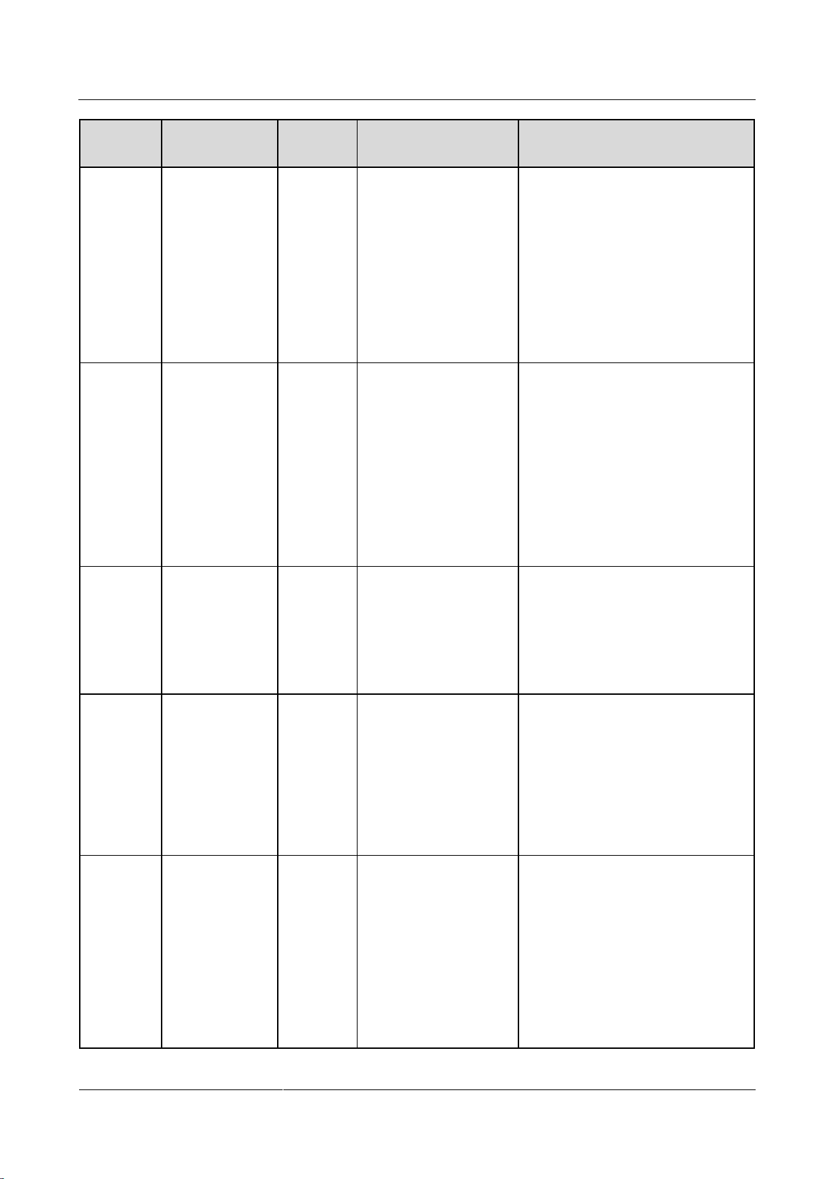
Alarm ID
Alarm Name
Alarm
Severity
Possible Cause
Suggestion
2034
Grid
Overvoltage
Major
Cause ID = 1
The grid voltage
exceeds the higher
threshold or the high
voltage duration has
lasted for more than the
value specified by
HVRT.
1. Check whether the grid
connection voltage exceeds the
upper threshold. If yes, contact
the local power operator.
2. If you have confirmed that the
grid connection voltage exceeds
the upper threshold and obtained
the consent of the local power
operator, modify the overvoltage
protection thresholds.
3. Check whether the peak grid
voltage exceeds the upper
threshold.
2035
Unbalanced
Grid Voltage
Major
The difference between
grid phase voltages
exceeds the upper
threshold.
1. Check that the grid voltage is
within the normal range.
2. Check the connection of the AC
output power cable.
3. If the cable connection is proper
but the alarm occurs frequently
and affects the power production
of the PV plant, contact the local
power operator.
2036
Grid
Overfrequency
Major
Cause ID = 1
Power grid exception:
The actual grid
frequency is higher than
the local power grid
standard.
1. If the alarm occurs accidentally,
the power grid may be abnormal
temporarily. The SUN2000
automatically recovers after
detecting that the power grid
becomes normal.
2. If the alarm occurs frequently,
check whether the grid frequency
is within the acceptable range. If
no, contact the local power
operator. If yes, modify the grid
overfrequency protection
threshold with the consent of the
local power operator.
2037
Grid
Underfrequency
Major
Cause ID = 1
Power grid exception:
The actual grid
frequency is lower than
the local power grid
standard.
1. If the alarm occurs accidentally,
the power grid may be abnormal
temporarily. The SUN2000
automatically recovers after
detecting that the power grid
becomes normal.
2. If the alarm occurs frequently,
check whether the grid frequency
is within the acceptable range. If
no, contact the local power
operator. If yes, modify the grid
underfrequency protection
threshold with the consent of the
local power operator.
Page 69
SUN2000-(2KTL-5KTL)-L0
User Manual
7 System Maintenance
Issue 01 (2018-08-30)
Copyright © Huawei Technologies Co., Ltd.
63
Alarm ID
Alarm Name
Alarm
Severity
Possible Cause
Suggestion
2038
Unstable Grid
Frequency
Major
Cause ID = 1
Power grid exception:
The actual grid
frequency change rate
does not comply with
the local power grid
standard.
1. If the alarm occurs accidentally,
the power grid may be abnormal
temporarily. The SUN2000
automatically recovers after
detecting that the power grid
becomes normal.
2. If the alarm occurs frequently,
check whether the grid frequency
is within the acceptable range. If
no, contact the local power
operator.
2039
Output
Overcurrent
Major
Cause ID = 1
The grid voltage drops
dramatically or the
power grid is
short-circuited. As a
result, the inverter
transient output current
exceeds the upper
threshold and therefore
the inverter protection is
triggered.
1. The SUN2000 monitors its
external working conditions in
real time. The SUN2000
automatically recovers after the
fault is rectified.
2. If the alarm occurs frequently and
affects the power production of
the PV plant, check whether the
output is short-circuited. If the
fault persists, contact your dealer.
2040
Output DC
Component
Overhigh
Major
Cause ID = 1
The DC component of
the SUN2000 output
current exceeds the
specified upper
threshold.
1. The SUN2000 monitors its
external working conditions in
real time. The SUN2000
automatically recovers after the
fault is rectified.
2. If the alarm occurs frequently,
contact your dealer.
2051
Abnormal
Residual Current
Major
Cause ID = 1
The insulation
impedance of the input
side to PE decreases
when the SUN2000 is
operating.
1. If the alarm occurs accidentally,
the external power cable may be
abnormal temporarily. The
SUN2000 automatically recovers
after the fault is rectified.
2. If the alarm occurs frequently or
persists, check that the impedance
between the PV string and ground
is not below the lower threshold.
2061
Abnormal
Grounding
Major
Cause ID = 1
The protective
earthing (PE) cable
for the SUN2000 is
not connected.
The voltage between
the SUN2000 neutral
wire and ground
exceeds the upper
threshold.
1. Check that the PE cable for the
SUN2000 is connected properly.
2. If the SUN2000 is connected to
the TN power grid, check
whether the voltage of the neutral
wire to ground is normal.
3. Check whether the output is
connected to an isolation
transformer. If so, set Grounding
inspection to Disable.
Page 70
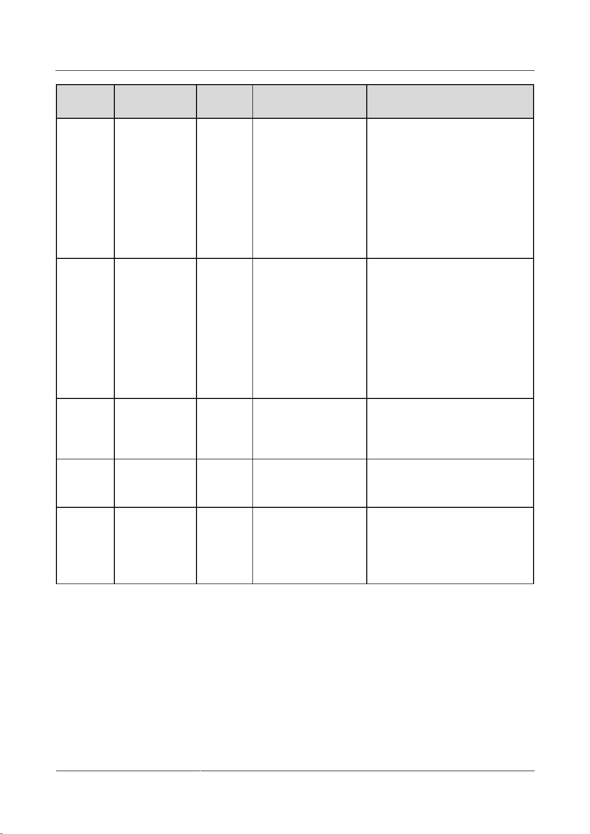
SUN2000-(2KTL-5KTL)-L0
User Manual
7 System Maintenance
Issue 01 (2018-08-30)
Copyright © Huawei Technologies Co., Ltd.
64
Alarm ID
Alarm Name
Alarm
Severity
Possible Cause
Suggestion
2062
Low Insulation
Resistance
Major
Cause ID = 1
The PV string is
short-circuited to PE.
The PV string is
installed in a moist
environment for a
long time.
1. Check the impedance between
the PV array output and PE, and
eliminate short circuits and poor
insulation points.
2. Check that the SUN2000 PE
cable is correctly connected.
3. If you are sure that the impedance
is less than the default value in a
cloudy or rainy environment,
reset Insulation resistance
protection.
2063
Overtemperature
Major
Cause ID = 1
The SUN2000 is
installed in a place
with poor
ventilation.
The ambient
temperature exceeds
the upper threshold.
The SUN2000 is not
working properly.
Check the ventilation and
ambient temperature at the
SUN2000 installation position.
If the ventilation is poor or the
ambient temperature exceeds the
upper threshold, improve the
ventilation and heat dissipation.
If the ventilation and ambient
temperature both meet
requirements, contact your dealer.
2064
Device Fault
Major
Cause ID = 1–12
An unrecoverable fault
occurs on a circuit
inside the SUN2000.
Turn off the AC output switch and
DC input switch, and then turn them
on after 5 minutes. If the fault
persists, contact your dealer.
2065
Upgrade Failed
Major
Cause ID = 1-4
The upgrade does not
end normally.
1. Perform an upgrade again.
2. If the upgrade fails several times,
contact your dealer.
61440
Monitoring Unit
Faulty
Minor
Cause ID = 1
The flash memory is
insufficient.
The flash memory
has bad sectors.
Contact your dealer to rectify the
fault.
Page 71
SUN2000-(2KTL-5KTL)-L0
User Manual
7 System Maintenance
Issue 01 (2018-08-30)
Copyright © Huawei Technologies Co., Ltd.
65
Alarm ID
Alarm Name
Alarm
Severity
Possible Cause
Suggestion
2067
Faulty Power
Collector
Major
Cause ID = 1
In Grid Connection
with Zero Power
mode, the power
collector
communication is
interrupted.
In Maximum Use of
Self-Produced Power
mode, the power
collector
communication is
interrupted.
1. Check that the preset power
collector model is the same as the
actual model.
2. Check that the preset
communications parameters for
the power collector are the same
as the actual configurations.
3. Check that the power collector is
powered on and the RS485
communications cable is
correctly connected.
Contact your dealer if all failure analysis procedures listed above are completed and the fault still exists.
Page 72

SUN2000-(2KTL-5KTL)-L0
User Manual
8 Handling the SUN2000
Issue 01 (2018-08-30)
Copyright © Huawei Technologies Co., Ltd.
66
8 Handling the SUN2000
8.1 Removing the SUN2000
Procedure
Step 1 Power off the system by following the instructions in 6.3 Powering Off the System.
Step 2 Disconnect all cables from the SUN2000, including signal cables, DC input power cables, AC
output power cables, and PE cables.
Step 3 Remove the WiFi antenna or 4G module from the SUN2000.
Step 4 Remove the SUN2000 from the mounting bracket.
Step 5 Remove the mounting bracket.
----End
8.2 Packing the SUN2000
If the original packaging is available, put the SUN2000 inside it and then seal it using
adhesive tape.
If the original packaging is not available, put the SUN2000 inside a suitable cardboard
box and seal it properly.
8.3 Disposing of the SUN2000
If the SUN2000 service life expires, dispose of it according to the local disposal rules for
electrical equipment and electronic component waste.
Page 73
SUN2000-(2KTL-5KTL)-L0
User Manual
9 Technical Specifications
Issue 01 (2018-08-30)
Copyright © Huawei Technologies Co., Ltd.
67
Efficiency
Item
SUN2000-2KTL-L
0
SUN2000-3KTL-L
0
SUN2000-4KTL-L
0
SUN2000-5KTL-L
0
Maximum
efficiency
98.5%
98.5%
98.5%
98.5%
European weighted
efficiency
97%
97.6%
97.9%
98%
Item
SUN2000-2KTL-L
0
SUN2000-3KTL-L
0
SUN2000-4KTL-L
0
SUN2000-5KTL-L
0
Maximum input
voltage
600 V
Maximum input
current (per MPPT)
11 A
Maximum
short-circuit current
(per MPPT)
15 A
Maximum inverter
backfeed current to
the PV array
0 A
Minimum startup
voltage
120 V
MPPT voltage
range
90–500 V
*/85
120–480 V
160–480 V
210–480 V
260–480 V
Rated input voltage
380 V
9 Technical Specifications
Input
Page 74
SUN2000-(2KTL-5KTL)-L0
User Manual
9 Technical Specifications
Issue 01 (2018-08-30)
Copyright © Huawei Technologies Co., Ltd.
68
Item
SUN2000-2KTL-L
0
SUN2000-3KTL-L
0
SUN2000-4KTL-L
0
SUN2000-5KTL-L
0
Number of inputs
2
Number of MPP
trackers
2
Output
Item
SUN2000-2KTL-L
0
SUN2000-3KTL-L
0
SUN2000-4KTL-L
0
SUN2000-5KTL-L
0
Rated output power
2 kW
3 kW
4 kW
5 kW
Maximum apparent
power
2.2 kVA
3.3 kVA
4.4 kVA
5.5 kVA
Rated output
voltage
220 V AC/230 V AC/240 V AC
Adapted grid
frequency
50/60 Hz
Maximum output
current
10 A
15 A
20 A
25 A
Power factor
0.8 leading... 0.8 lagging
Maximum total
harmonic distortion
(rated power)
≤ 3%
Item
SUN2000-2KTL-L
0
SUN2000-3KTL-L
0
SUN2000-4KTLL0
SUN2000-5KTL-L
0
Anti-islanding
protection
Supported
Input reverse
polarity protection
Supported
Output short-circuit
protection
Supported
RCMU
Supported
AC surge protection
Supported
DC surge protection
Supported
Protection
Page 75
SUN2000-(2KTL-5KTL)-L0
User Manual
9 Technical Specifications
Issue 01 (2018-08-30)
Copyright © Huawei Technologies Co., Ltd.
69
Item
SUN2000-2KTL-L
0
SUN2000-3KTL-L
0
SUN2000-4KTLL0
SUN2000-5KTL-L
0
Output overvoltage
protection
Supported
Insulation resistance
detection
Supported
Item
SUN2000-2KTL-L
0
SUN2000-3KTL-L
0
SUN2000-4KTL-L
0
SUN2000-5KTL-L
0
Display
LED
WiFi
Supported
RS485
Supported
4G
Optional
Item
SUN2000-2KTL-L
0
SUN2000-3KTL-L
0
SUN2000-4KTL-L
0
SUN2000-5KTL-L
0
Topology
Transformerless
Ingress Protection
Rating
IP65
Cooling mode
Natural cooling
Dimensions (W x H
x D)
375 mm x 375 mm x 117 mm (excluding the mounting plate)/375 mm x 375 mm x 149.5
mm (including the mounting plate)/440 mm x 440mm x 231mm (including the package)
Weight
10.6kg (excluding the mounting plate)/13.2kg (including the package)
Operating
temperature
–30°C to +60°C (derated above +45°C)
Humidity
0%–100% RH
Operating altitude
0–4000 m (derated above 2000 m)
Communication
Common parameters
Page 76
SUN2000-(2KTL-5KTL)-L0
User Manual
A Grid Codes
Issue 01 (2018-08-30)
Copyright © Huawei Technologies Co., Ltd.
70
A Grid Codes
No.
Grid Code
Description
Grid Voltage
Grid Frequency
1
EN50438-NL
Netherlands
power grid
230 V
50 Hz
Grid codes are subject to change. The listed codes are for your reference only.
Table A-1 Grid codes (SUN2000-2KTL/3KTL/4KTL/5KTL-L0)
Page 77

SUN2000-(2KTL-5KTL)-L0
User Manual
B Acronyms and Abbreviations
Issue 01 (2018-08-30)
Copyright © Huawei Technologies Co., Ltd.
71
B Acronyms and Abbreviations
A AC
alternating current
D DC
direct current
I
ID
identifier
L
LED
light emitting diode
LVRT
low voltage ride-through
M
MAC
Media Access Control
MPPT
maximum power point tracking
P PC
personal computer
PE
protective earthing
PV
photovoltaic
R
RCMU
residual current monitoring unit
Page 78

SUN2000-(2KTL-5KTL)-L0
User Manual
B Acronyms and Abbreviations
Issue 01 (2018-08-30)
Copyright © Huawei Technologies Co., Ltd.
72
RH
relative humidity
S
SN
serial number
T
THDi
total distortion of the input current
waveform
W
WEEE
waste electrical and electronic equipment
WiFi
Wireless Fidelity
 Loading...