

Page 1
SUN2000-(12KTL-25KTL)-M5 Series
User Manual
Issue 03
Date 2023-02-15
HUAWEI DIGITAL POWER TECHNOLOGIES CO., LTD.
Page 2

Copyright © Huawei Digital Power Technologies Co., Ltd. 2023. All rights reserved.
No part of this document may be reproduced or transmitted in any form or by any means without prior
written consent of Huawei Digital Power Technologies Co., Ltd.
Trademarks and Permissions
and other Huawei trademarks are the property of Huawei Technologies Co., Ltd.
All other trademarks and trade names mentioned in this document are the property of their respective
holders.
Notice
The purchased products, services and features are stipulated by the contract made between Huawei
Digital Power Technologies Co., Ltd. and the customer. All or part of the products, services and features
described in this document may not be within the purchase scope or the usage scope. Unless otherwise
specied in the contract, all statements, information, and recommendations in this document are
provided "AS IS" without warranties, guarantees or representations of any kind, either express or implied.
The information in this document is subject to change without notice. Every eort has been made in the
preparation of this document to ensure accuracy of the contents, but all statements, information, and
recommendations in this document do not constitute a warranty of any kind, express or implied.
Huawei Digital Power Technologies Co., Ltd.
Address: Huawei Digital Power Antuoshan Headquarters
Futian,Shenzhen 518043
People's Republic of China
Website: https://e.huawei.com
Issue 03 (2023-02-15) Copyright © Huawei Digital Power Technologies Co., Ltd. i
Page 3
SUN2000-(12KTL-25KTL)-M5 Series
User Manual About This Document
About This Document
Purpose
This document describes the SUN2000-12KTL-M5, SUN2000-15KTL-M5,
SUN2000-17KTL-M5, SUN2000-20KTL-M5, SUN2000-25KTL-M5, SUN2000-15KTLZHM5, SUN2000-17KTL-ZHM5, SUN2000-20KTL-ZHM5, and SUN2000-25KTLZHM5 (also referred to as SUN2000) in terms of their installation, electrical
connections, commissioning, maintenance, and troubleshooting. Before installing
and operating the SUN2000, ensure that you are familiar with the safety
precautions as well as features and functions of the SUN2000 provided in this
document.
Intended Audience
This document is intended for:
● Installers
● Users
Symbol Conventions
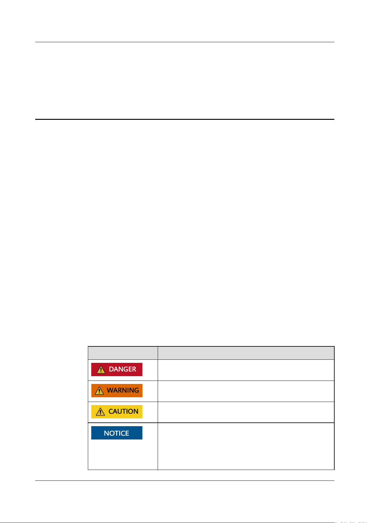
The symbols that may be found in this document are
Symbol
dened as follows.
Description
Indicates a hazard with a high level of risk which, if not
avoided, will result in death or serious injury.
Indicates a hazard with a medium level of risk which, if
not avoided, could result in death or serious injury.
Indicates a hazard with a low level of risk which, if not
avoided, could result in minor or moderate injury.
Indicates a potentially hazardous situation which, if not
avoided, could result in equipment damage, data loss,
performance deterioration, or unanticipated results.
NOTICE is used to address practices not related to
personal injury.
Issue 03 (2023-02-15) Copyright © Huawei Digital Power Technologies Co., Ltd. ii
Page 4
SUN2000-(12KTL-25KTL)-M5 Series
User Manual About This Document
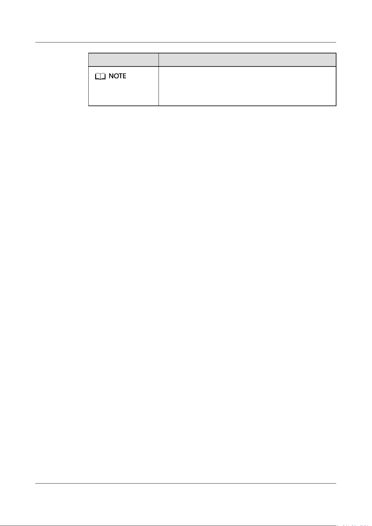
Symbol Description
Supplements the important information in the main text.
NOTE is used to address information not related to
personal injury, equipment damage, and environment
deterioration.
Change History
Changes between document issues are cumulative. The latest document issue
contains all updates made in previous issues.
Issue 03 (2023-02-15)
Updated 1 Safety Information.
Updated 2.1 Product Introduction.
Updated 5.2 Preparing Cables.
Updated 5.5 Installing AC Output Power Cables and Signal Cables.
Updated A Grid Codes.
Updated F NS Protection.
Issue 02 (2022-10-20)
Updated 4.6 (Optional) Installing a Junction Box.
Updated 5.2 Preparing Cables.
Updated 5.5 Installing AC Output Power Cables and Signal Cables.
Updated 7.2.1.1 Grid-tied Point Control.
Updated 8.3 Troubleshooting.
Updated 10.1 SUN2000-(15KTL-25KTL)-ZHM5 Technical
Updated 10.2 SUN2000-(12KTL-25KTL)-M5 Technical
Specications.
Specications.
Updated E Rapid Shutdown.
Issue 01 (2022-06-15)
This issue is used for rst oce application (FOA).
Issue 03 (2023-02-15) Copyright © Huawei Digital Power Technologies Co., Ltd. iii
Page 5

SUN2000-(12KTL-25KTL)-M5 Series
User Manual Contents
Contents
About This Document................................................................................................................ ii
1 Safety Information.................................................................................................................. 1
1.1 Personal Safety.........................................................................................................................................................................2
1.2 Electrical Safety........................................................................................................................................................................4
1.3 Environment Requirements................................................................................................................................................. 6
1.4 Mechanical Safety................................................................................................................................................................... 8
2 Overview................................................................................................................................. 13
2.1 Product Introduction............................................................................................................................................................ 13
2.2 Appearance............................................................................................................................................................................. 16
2.3 Label Description.................................................................................................................................................................. 18
2.4 Working Principles................................................................................................................................................................ 18
2.4.1 Working Modes.................................................................................................................................................................. 18
2.4.2 Circuit Diagram.................................................................................................................................................................. 19
3 SUN2000 Storage...................................................................................................................21
4 Installation..............................................................................................................................22
4.1 Checking Before Installation............................................................................................................................................. 22
4.2 Tools.......................................................................................................................................................................................... 23
4.3 Determining the Installation Position............................................................................................................................24
4.3.1 Environment Requirements............................................................................................................................................24
4.3.2 Space Requirements......................................................................................................................................................... 25
4.4 Moving an Inverter............................................................................................................................................................... 26
4.5 Installing an Inverter............................................................................................................................................................27
4.6 (Optional) Installing a Junction Box.............................................................................................................................. 29
5 Electrical Connections.......................................................................................................... 31
5.1 Precautions.............................................................................................................................................................................. 31
5.2 Preparing Cables................................................................................................................................................................... 32
5.3 Connecting the Ground Cable.......................................................................................................................................... 35
5.4 Installing DC Input Power Cables....................................................................................................................................37
5.5 Installing AC Output Power Cables and Signal Cables............................................................................................ 40
5.6 (Optional) Installing the Smart Dongle and Anti-theft Components................................................................ 45
6 Commissioning.......................................................................................................................46
Issue 03 (2023-02-15) Copyright © Huawei Digital Power Technologies Co., Ltd. iv
Page 6

SUN2000-(12KTL-25KTL)-M5 Series
User Manual Contents
6.1 Check Before Power-On......................................................................................................................................................46
6.2 Powering On the System....................................................................................................................................................47
7 Man-Machine Interactions.................................................................................................. 53
7.1 App Commissioning............................................................................................................................................................. 53
7.1.1 Downloading the FusionSolar App..............................................................................................................................53
7.1.2 (Optional) Registering an Installer Account............................................................................................................ 54
7.1.3 Creating a PV Plant and a User.................................................................................................................................... 55
7.1.4 (Optional) Setting the Physical Layout of the Smart PV Optimizers.............................................................. 55
7.1.5 Detecting Optimizer Disconnection............................................................................................................................ 55
7.2 Parameters Settings............................................................................................................................................................. 56
7.2.1 Energy Control.................................................................................................................................................................... 56
7.2.1.1 Grid-tied Point Control................................................................................................................................................. 56
7.2.1.2 Apparent Power Control on the Inverter Output Side...................................................................................... 61
7.2.2 AFCI........................................................................................................................................................................................ 62
8 Maintenance...........................................................................................................................65
8.1 Powering O the System................................................................................................................................................... 65
8.2 Routine Maintenance.......................................................................................................................................................... 66
8.3 Troubleshooting.....................................................................................................................................................................67
8.4 Replacing a Fan..................................................................................................................................................................... 77
9 Handling the Inverter...........................................................................................................78
9.1 Removing the SUN2000..................................................................................................................................................... 78
9.2 Packing the SUN2000..........................................................................................................................................................78
9.3 Disposing of the SUN2000................................................................................................................................................ 78
10 Technical
10.1 SUN2000-(15KTL-25KTL)-ZHM5 Technical
10.2 SUN2000-(12KTL-25KTL)-M5 Technical Specications.........................................................................................86
Specications.....................................................................................................79
Specications................................................................................... 79
A Grid Codes...............................................................................................................................94
B Device Commissioning......................................................................................................... 97
C Resetting Password...............................................................................................................99
D Locating Insulation Resistance Faults........................................................................... 100
E Rapid Shutdown.................................................................................................................. 104
F NS Protection....................................................................................................................... 106
G
Precongured Certicate Disclaimer.............................................................................107
H Acronym and Abbreviation.............................................................................................. 108
Issue 03 (2023-02-15) Copyright © Huawei Digital Power Technologies Co., Ltd. v
Page 7

SUN2000-(12KTL-25KTL)-M5 Series
User Manual 1 Safety Information
1 Safety Information
Statement
Before transporting, storing, installing, operating, using, and/or maintaining the
equipment, read this document, strictly follow the instructions provided herein,
and follow all the safety instructions on the equipment and in this document. In
this document, "equipment" refers to the products, software, components, spare
parts, and/or services related to this document; "the Company" refers to the
manufacturer (producer), seller, and/or service provider of the equipment; "you"
refers to the entity that transports, stores, installs, operates, uses, and/or
maintains the equipment.
The Danger, Warning, Caution, and Notice statements described in this
document do not cover all the safety precautions. You also need to comply with
relevant international, national, or regional standards and industry practices. The
Company shall not be liable for any consequences that may arise due to
violations of safety requirements or safety standards concerning the design,
production, and usage of the equipment.
The equipment should be used in an environment that meets the design
specications. Otherwise, the equipment may be faulty, malfunctioning, or
damaged, which is not covered under the warranty. The Company shall not be
liable for any property loss, personal injury, or even death caused thereby.
Comply with applicable laws, regulations, standards, and specications during
transportation, storage, installation, operation, use, and maintenance.
Do not perform reverse engineering, decompilation, disassembly, adaptation,
implantation, or other derivative operations on the equipment software. Do not
study the internal implementation logic of the equipment, obtain the source code
of the equipment software, violate intellectual property rights, or disclose any of
the performance test results of the equipment software.
The Company shall not be liable for any of the following circumstances or
their consequences:
● The equipment is damaged due to force majeure such as earthquakes,
volcanic eruptions, debris ows, lightning strikes, res, wars, armed conicts,
typhoons, hurricanes, tornadoes, and other extreme weather conditions.
oods,
● The equipment is operated beyond the conditions
Issue 03 (2023-02-15) Copyright © Huawei Digital Power Technologies Co., Ltd. 1
specied in this document.
Page 8
D ANGER
D ANGER
D ANGER
D ANGER
SUN2000-(12KTL-25KTL)-M5 Series
User Manual 1 Safety Information
● The equipment is installed or used in environments that do not comply with
international, national, or regional standards.
● You fail to follow the operation instructions and safety precautions on the
product and in the document.
● You remove or modify the product or modify the software code without
authorization.
● You or a third party authorized by you cause the equipment damage during
transportation.
● The equipment is damaged due to storage conditions that do not meet the
requirements
● You fail to prepare materials and tools that comply with local laws,
regulations, and related standards.
● The equipment is damaged due to your or a third party's negligence,
intentional breach, gross negligence, or improper operations, or other reasons
not related to the Company.
specied in the product document.
1.1 Personal Safety
Ensure that power is o during installation. Do not install or remove a cable with
power on. Transient contact between the core of the cable and the conductor will
generate electric arcs or sparks, which may cause a
Non-standard and improper operations on the energized equipment may cause
re, electric shocks, or explosion, resulting in property damage, personal injury, or
even death.
Before operations, remove conductive objects such as watches, bracelets, bangles,
rings, and necklaces to prevent electric shocks.
re or personal injury.
During operations, use dedicated insulated tools to prevent electric shocks or short
circuits. The dielectric withstanding voltage level must comply with local laws,
regulations, standards, and
Issue 03 (2023-02-15) Copyright © Huawei Digital Power Technologies Co., Ltd. 2
specications.
Page 9
WARNING
SUN2000-(12KTL-25KTL)-M5 Series
User Manual 1 Safety Information
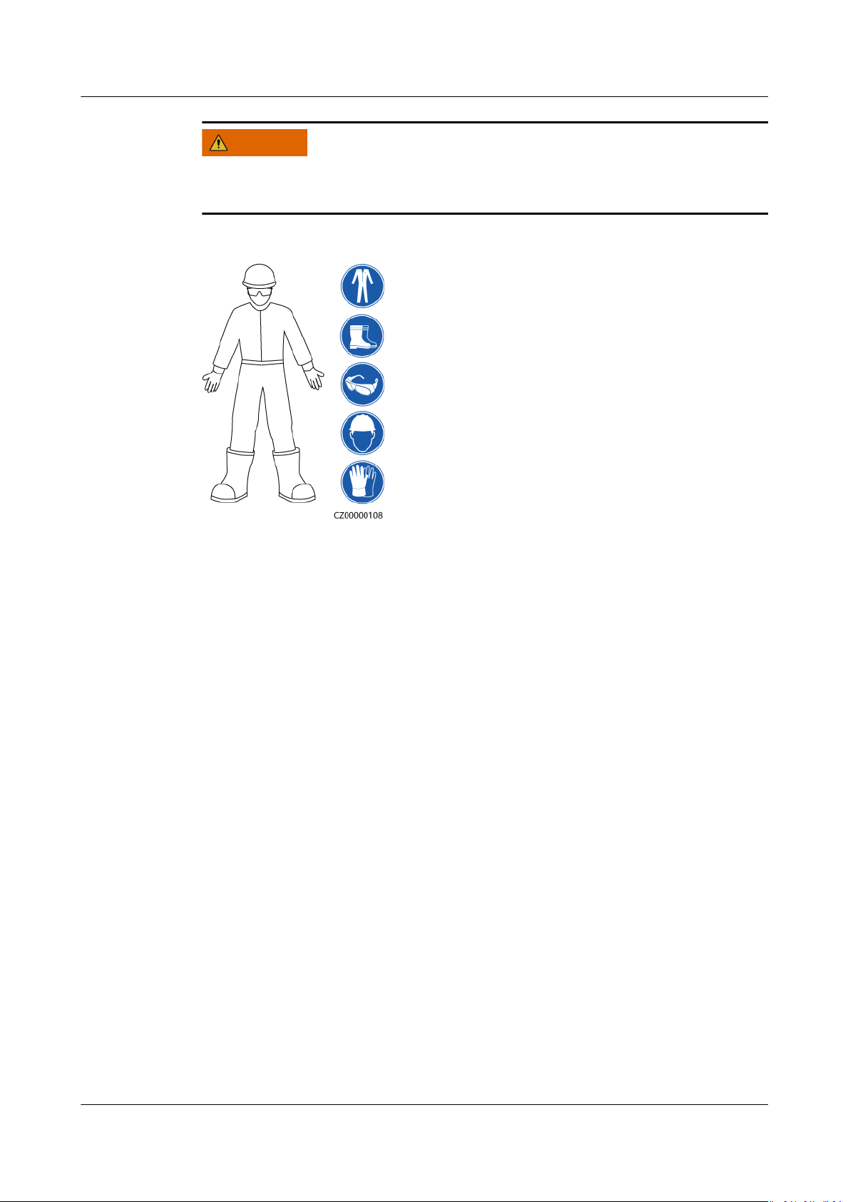
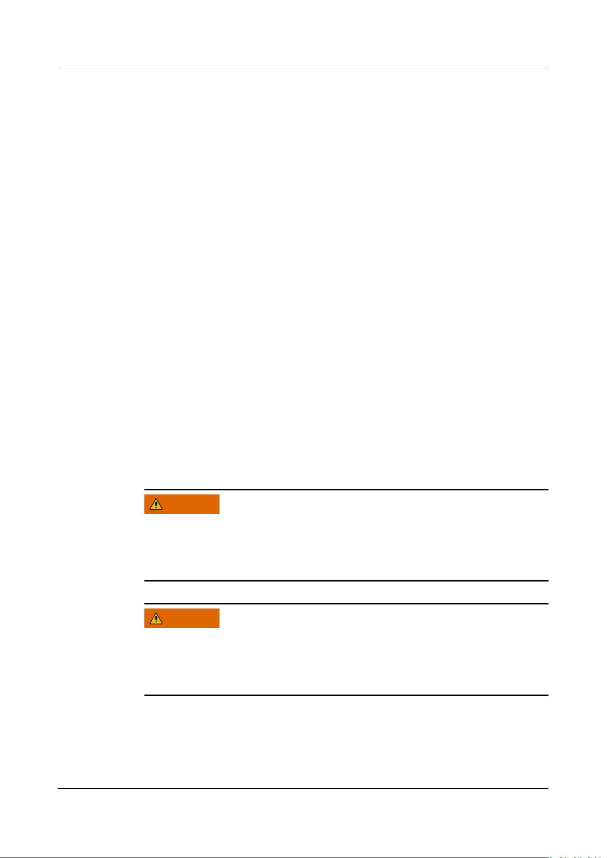
During operations, wear personal protective equipment such as protective
clothing, insulated shoes, goggles, safety helmets, and insulated gloves.
Figure 1-1 Personal protective equipment
General Requirements
● Do not stop protective devices. Pay attention to the warnings, cautions, and
related precautionary measures in this document and on the equipment.
● If there is a likelihood of personal injury or equipment damage during
operations, immediately stop, report the case to the supervisor, and take
feasible protective measures.
● Do not power on the equipment before it is installed or
professionals.
● Do not touch the power supply equipment directly or with conductors such as
damp objects. Before touching any conductor surface or terminal, measure
the voltage at the contact point to ensure that there is no risk of electric
shock.
● Do not touch operating equipment because the enclosure is hot.
● Do not touch a running fan with your hands, components, screws, tools, or
boards. Otherwise, personal injury or equipment damage may occur.
● In the case of a
and activate the re alarm or call emergency services. Do not enter the
aected building or equipment area under any circumstances.
Personnel Requirements
conrmed by
re, immediately leave the building or the equipment area
Issue 03 (2023-02-15) Copyright © Huawei Digital Power Technologies Co., Ltd. 3
● Only professionals and trained personnel are allowed to operate the
equipment.
– Professionals: personnel who are familiar with the working principles and
structure of the equipment, trained or experienced in equipment
operations and are clear of the sources and degree of various potential
hazards in equipment installation, operation, maintenance
Page 10
D ANGER
D ANGER
D ANGER
WARNING
SUN2000-(12KTL-25KTL)-M5 Series
User Manual 1 Safety Information
– Trained personnel: personnel who are trained in technology and safety,
have required experience, are aware of possible hazards on themselves in
certain operations, and are able to take protective measures to minimize
the hazards on themselves and other people
● Personnel who plan to install or maintain the equipment must receive
adequate training, be able to correctly perform all operations, and understand
all necessary safety precautions and local relevant standards.
● Only
● Only
● Personnel who will perform special tasks such as electrical operations,
● Only authorized professionals are allowed to replace the equipment or
● Only personnel who need to work on the equipment are allowed to access
qualied professionals or trained personnel are allowed to install,
operate, and maintain the equipment.
qualied professionals are allowed to remove safety facilities and inspect
the equipment.
working at heights, and operations of special equipment should possess the
required local
components (including software).
the equipment.
1.2 Electrical Safety
Before connecting cables, ensure that the equipment is intact. Otherwise, electric
shocks or re may occur.
qualications.
Non-standard and improper operations may result in re or electric shocks.
Prevent foreign matter from entering the equipment during operations. Otherwise,
equipment damage, load power derating, power failure, or personal injury may
occur.
For the equipment that needs to be grounded, install the ground cable rst when
installing the equipment and remove the ground cable last when removing the
equipment.
Issue 03 (2023-02-15) Copyright © Huawei Digital Power Technologies Co., Ltd. 4
Page 11
CA UTION
SUN2000-(12KTL-25KTL)-M5 Series
User Manual 1 Safety Information
Do not route cables behind the air intake and exhaust vents of the equipment.
General Requirements
● Follow the procedures described in the document for installation, operation,
and maintenance. Do not reconstruct or alter the equipment, add
components, or change the installation sequence without permission.
● Obtain approval from the national or local electric utility company before
connecting the equipment to the grid.
● Observe the power plant safety regulations, such as the operation and work
ticket mechanisms.
● Install temporary fences or warning ropes and hang "No Entry" signs around
the operation area to keep unauthorized personnel away from the area.
● Before installing or removing power cables, turn
equipment and its upstream and downstream switches.
● Before performing operations on the equipment, check that all tools meet the
requirements and record the tools. After the operations are complete, collect
all of the tools to prevent them from being left inside the equipment.
● Before installing power cables, check that cable labels are correct and cable
terminals are insulated.
● When installing the equipment, use a torque tool of a proper measurement
range to tighten the screws. When using a wrench to tighten the screws,
ensure that the wrench does not tilt and the torque error does not exceed
10% of the
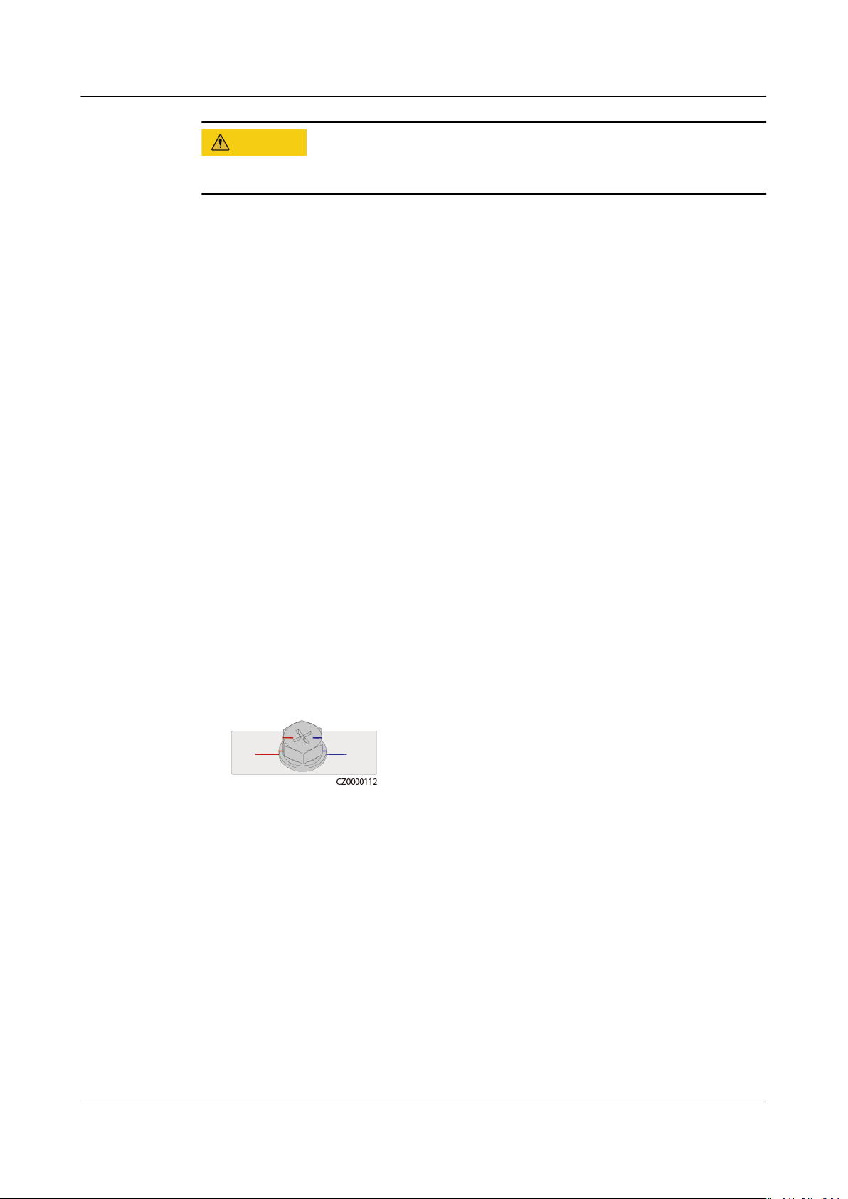
● Ensure that bolts are tightened with a torque tool and marked in red and blue
after double-check. Installation personnel mark tightened bolts in blue.
Quality inspection personnel
mark them in red. (The marks should cross the edges of the bolts.)
specied value.
conrm that the bolts are tightened and then
o the switches of the
Issue 03 (2023-02-15) Copyright © Huawei Digital Power Technologies Co., Ltd. 5
● If the equipment has multiple inputs, disconnect all the inputs before
operating the equipment.
● Before maintaining a downstream electrical device supply or power
distribution device, turn
● During equipment maintenance, attach "Do not switch on" labels near the
upstream and downstream switches or circuit breakers as well as warning
signs to prevent accidental connection. The equipment can be powered on
only after troubleshooting is complete.
● Do not open equipment panels.
● Check equipment connections periodically, ensuring that all screws are
securely tightened.
● Only
● Do not scrawl, damage, or block any labels or nameplates on the equipment.
qualied professionals can replace a damaged cable.
Promptly replace labels that have worn out.
o the output switch of its power supply equipment.
Page 12

D ANGER
SUN2000-(12KTL-25KTL)-M5 Series
User Manual 1 Safety Information
● Do not use solvents such as water, alcohol, or oil to clean electrical
components inside or outside of the equipment.
Grounding
● Ensure that the grounding impedance of the equipment complies with local
electrical standards.
● Ensure that the equipment is connected permanently to the protective
ground. Before operating the equipment, check its electrical connection to
ensure that it is reliably grounded.
● Do not work on the equipment in the absence of a properly installed ground
conductor.
● Do not damage the ground conductor.
Cabling Requirements
● When selecting, installing, and routing cables, follow local safety regulations
and rules.
● When routing power cables, ensure that there is no coiling or twisting. Do not
join or weld power cables. If necessary, use a longer cable.
● Ensure that all cables are properly connected and insulated, and meet
specications.
● Ensure that the slots and holes for routing cables are free from sharp edges,
and that the positions where cables are routed through pipes or cable holes
are equipped with cushion materials to prevent the cables from being
damaged by sharp edges or burrs.
● Ensure that cables of the same type are bound together neatly and straight
and that the cable sheath is intact. When routing cables of
ensure that they are away from each other without entanglement and
overlapping.
● Secure buried cables using cable supports and cable clips. Ensure that the
cables in the
cable deformation or damage during
● If the external conditions (such as the cable layout or ambient temperature)
change, verify the cable usage in accordance with the IEC-60364-5-52 or local
laws and regulations. For example, check that the current-carrying capacity
meets requirements.
● When routing cables, reserve at least 30 mm clearance between the cables
and heat-generating components or areas. This prevents deterioration or
damage to the cable insulation layer.
backll area are in close contact with the ground to prevent
backlling.
dierent types,
1.3 Environment Requirements
Do not expose the equipment to ammable or explosive gas or smoke. Do not
perform any operation on the equipment in such environments.
Issue 03 (2023-02-15) Copyright © Huawei Digital Power Technologies Co., Ltd. 6
Page 13
D ANGER
D ANGER
WARNING
WARNING
SUN2000-(12KTL-25KTL)-M5 Series
User Manual 1 Safety Information
Do not store any ammable or explosive materials in the equipment area.
Do not place the equipment near heat sources or re sources, such as smoke,
candles, heaters, or other heating devices. Overheat may damage the equipment
or cause a
re.
Install the equipment in an area far away from liquids. Do not install it under
areas prone to condensation, such as under water pipes and air exhaust vents, or
areas prone to water leakage, such as air conditioner vents, ventilation vents, or
feeder windows of the equipment room. Ensure that no liquid enters the
equipment to prevent faults or short circuits.
To prevent damage or re due to high temperature, ensure that the ventilation
vents or heat dissipation systems are not obstructed or covered by other objects
while the equipment is running.
General Requirements
● Ensure that the equipment is stored in a clean, dry, and well ventilated area
with proper temperature and humidity and is protected from dust and
condensation.
● Do not install or run the equipment beyond the technical
Otherwise, its performance and safety will be compromised.
● Do not install, use, or operate outdoor equipment and cables (including but
not limited to moving equipment, operating equipment and cables, inserting
connectors to or removing connectors from signal ports connected to outdoor
facilities, working at heights, performing outdoor installation, and opening
doors) in harsh weather conditions such as lightning, rain, snow, and level 6
or stronger wind.
● Do not install the equipment in an environment with dust, smoke, volatile or
corrosive gases, infrared and other radiations, organic solvents, or salty air.
● Do not install the equipment in an environment with conductive metal or
magnetic dust.
● Do not install the equipment in an area conducive for the growth of
microorganisms such as fungus or mildew.
● Do not install the equipment in an area with strong vibration, noise, or
electromagnetic interference.
specications.
Issue 03 (2023-02-15) Copyright © Huawei Digital Power Technologies Co., Ltd. 7
Page 14
WARNING
WARNING
SUN2000-(12KTL-25KTL)-M5 Series
User Manual 1 Safety Information
● Ensure that the site complies with local laws, regulations, and related
standards.
● Ensure that the ground in the installation environment is solid, free from
spongy or soft soil, and not prone to subsidence. The site must not be located
in a low-lying land or an area prone to water accumulation, and the
horizontal level of the site must be above the highest water level of that area
in history.
● Do not install the equipment in a position that may be submerged in water.
● If the equipment is installed in a place with abundant vegetation, in addition
to routine weeding, harden the ground underneath the equipment using
cement or gravel (recommended area: 3 m x 2.5 m).
● Do not install the equipment outdoors in salt-aected areas because it may
be corroded. A
coast or prone to sea breeze. Regions prone to sea breeze vary with weather
conditions (such as typhoons and monsoons) or terrains (such as dams and
hills).
● Before opening doors during the installation, operation, and maintenance of
the equipment, clean up any water, ice, snow, or other foreign objects on the
top of the equipment to prevent foreign objects from falling into the
equipment.
● When installing the equipment, ensure that the installation surface is solid
enough to bear the weight of the equipment.
● After installing the equipment, remove the packing materials such as cartons,
foam, plastics, and cable ties from the equipment area.
salt-aected area refers to the region within 500 m of the
1.4 Mechanical Safety
Ensure that all necessary tools are ready and inspected by a professional
organization. Do not use tools that have signs of scratches or fail to pass the
inspection or whose inspection validity period has expired. Ensure that the tools
are secure and not overloaded.
Do not drill holes into the equipment. Doing so may aect the sealing
performance and electromagnetic containment of the equipment and damage
components or cables inside. Metal shavings from drilling may short-circuit boards
inside the equipment.
General Requirements
● Repaint any paint scratches caused during equipment transportation or
installation in a timely manner. Equipment with scratches cannot be exposed
for an extended period of time.
Issue 03 (2023-02-15) Copyright © Huawei Digital Power Technologies Co., Ltd. 8
Page 15
SUN2000-(12KTL-25KTL)-M5 Series
User Manual 1 Safety Information
● Do not perform operations such as arc welding and cutting on the equipment
without evaluation by the Company.
● Do not install other devices on the top of the equipment without evaluation
by the Company.
● When performing operations over the top of the equipment, take measures to
protect the equipment against damage.
● Use correct tools and operate them in the correct way.
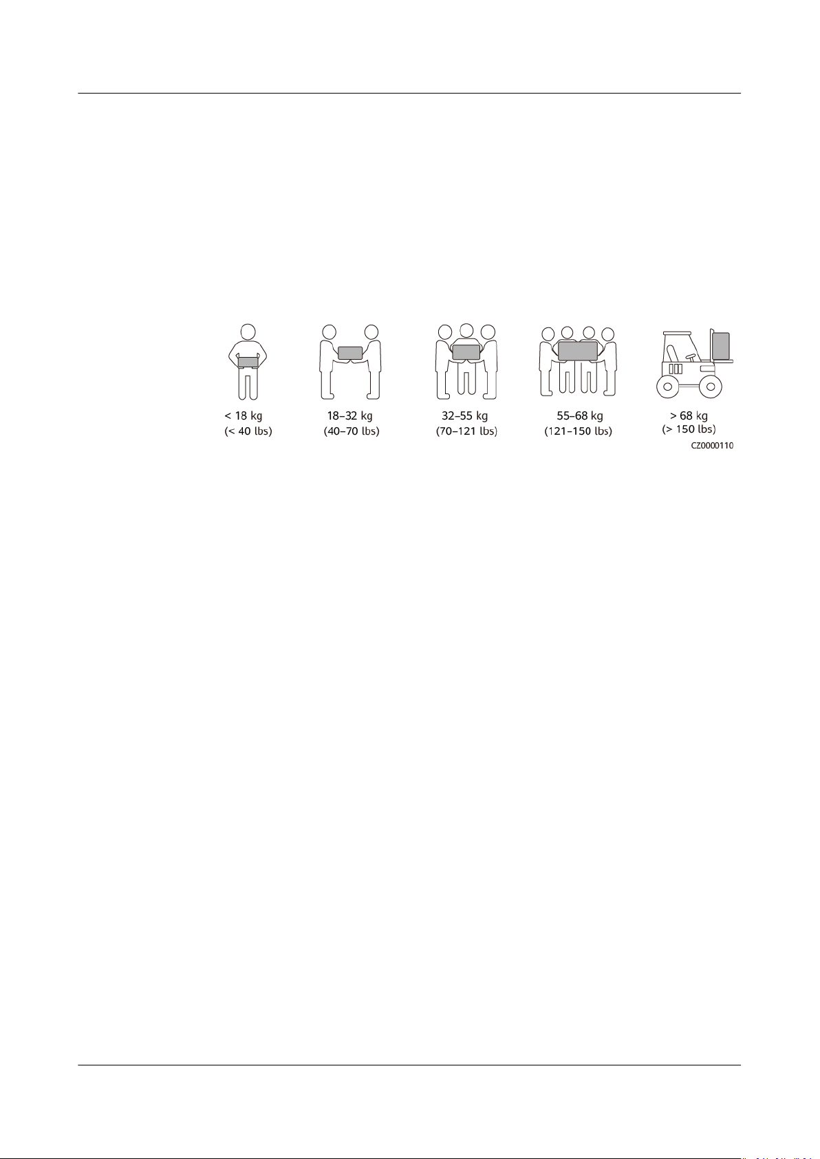
Moving Heavy Objects
● Be cautious to prevent injury when moving heavy objects.
● If multiple persons need to move a heavy object together, determine the
manpower and work division with consideration of height and other
conditions to ensure that the weight is equally distributed.
● If two persons or more move a heavy object together, ensure that the object
is lifted and landed simultaneously and moved at a uniform pace under the
supervision of one person.
● Wear personal protective gears such as protective gloves and shoes when
manually moving the equipment.
● To move an object by hand, approach to the object, squat down, and then lift
the object gently and stably by the force of the legs instead of your back. Do
not lift it suddenly or turn your body around.
● Do not quickly lift a heavy object above your waist. Place the object on a
workbench that is half-waist high or any other appropriate place, adjust the
positions of your palms, and then lift it.
● Move a heavy object stably with balanced force at an even and low speed. Put
down the object stably and slowly to prevent any collision or drop from
scratching the surface of the equipment or damaging the components and
cables.
● When moving a heavy object, be aware of the workbench, slope, staircase,
and slippery places. When moving a heavy object through a door, ensure that
the door is wide enough to move the object and avoid bumping or injury.
● When transferring a heavy object, move your feet instead of turning your
waist around. When lifting and transferring a heavy object, ensure that your
feet point to the target direction of movement.
● When transporting the equipment using a pallet truck or forklift, ensure that
the tynes are properly positioned so that the equipment does not topple.
Before moving the equipment, secure it to the pallet truck or forklift using
ropes. When moving the equipment, assign dedicated personnel to take care
of it.
● Choose sea or roads in good conditions for transportation as transportation
by railway or air is not supported. Avoid tilt or jolt during transportation.
Issue 03 (2023-02-15) Copyright © Huawei Digital Power Technologies Co., Ltd. 9
Page 16
SUN2000-(12KTL-25KTL)-M5 Series
User Manual 1 Safety Information
Using Ladders
● Use wooden or insulated ladders when you need to perform live-line working
at heights.
● Platform ladders with protective rails are preferred. Single ladders are not
recommended.
● Before using a ladder, check that it is intact and
capacity. Do not overload it.
● Ensure that the ladder is securely positioned and held rm.
conrm its load bearing
● When climbing up the ladder, keep your body stable and your center of
gravity between the side rails, and do not overreach to the sides.
● When a step ladder is used, ensure that the pull ropes are secured.
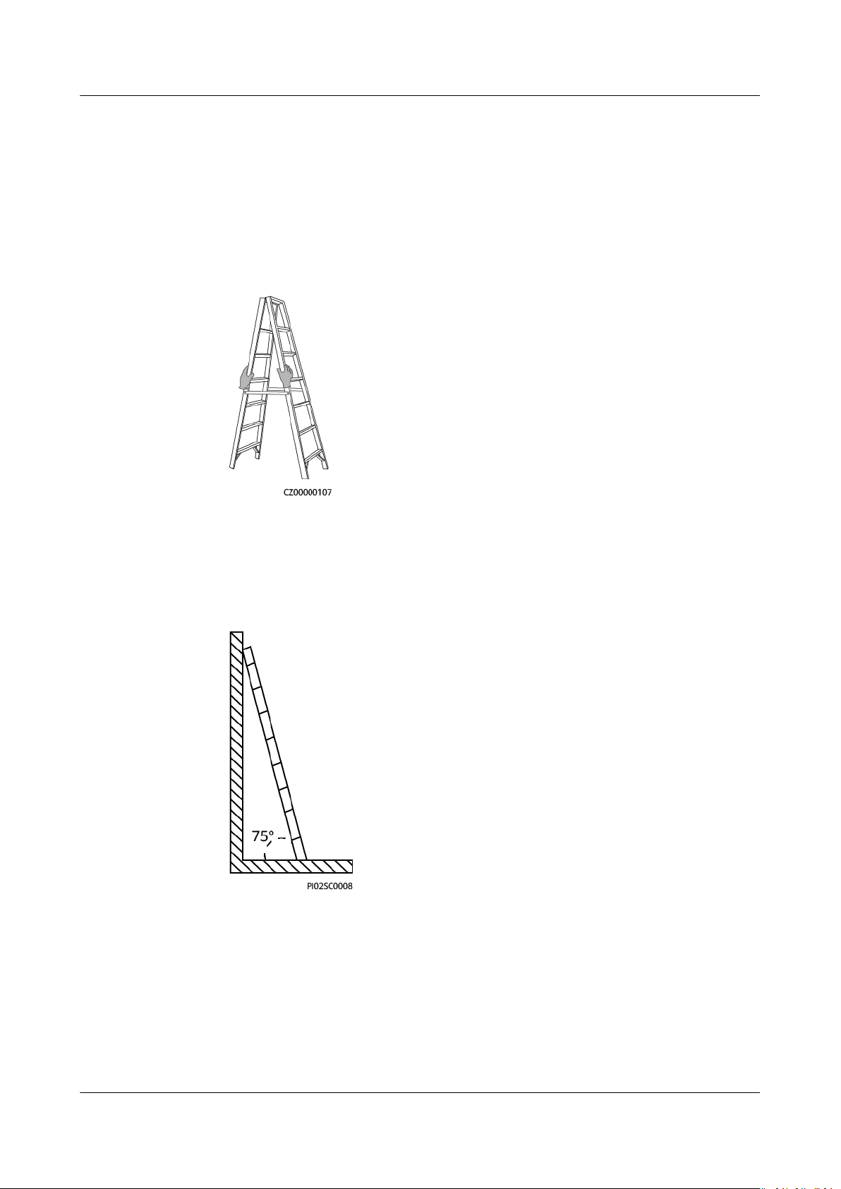
● If a single ladder is used, the recommended angle for the ladder against the
oor is 75 degrees, as shown in the following gure. A square can be used to
measure the angle.
● If a single ladder is used, ensure that the wider end of the ladder is at the
bottom, and take protective measures to prevent the ladder from sliding.
● If a single ladder is used, do not climb higher than the fourth rung of the
ladder from the top.
● If you use a single ladder to climb up to a platform, ensure that the ladder is
at least 1 m higher than the platform.
Issue 03 (2023-02-15) Copyright © Huawei Digital Power Technologies Co., Ltd. 10
Page 17
SUN2000-(12KTL-25KTL)-M5 Series
User Manual 1 Safety Information
Hoisting
● Only trained and qualied personnel are allowed to perform hoisting
operations.
● Install temporary warning signs or fences to isolate the hoisting area.
● Ensure that the foundation where hoisting is performed on meets the loadbearing requirements.
● Before hoisting objects, ensure that hoisting tools are
xed object or wall that meets the load-bearing requirements.
● During hoisting, do not stand or walk under the crane or the hoisted objects.
● Do not drag steel ropes and hoisting tools or bump the hoisted objects
against hard objects during hoisting.
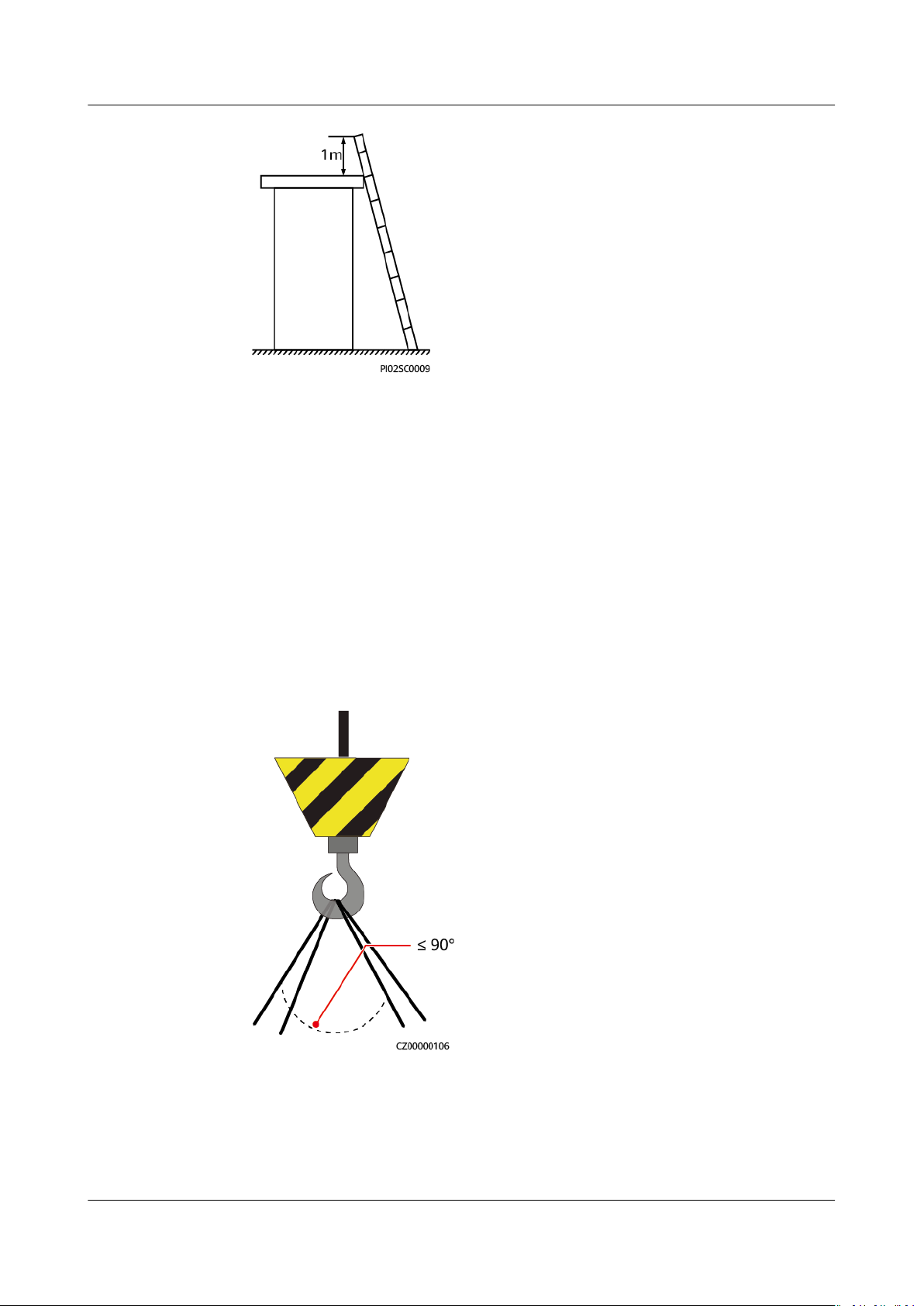
● Ensure that the angle between two hoisting ropes is no more than 90
degrees, as shown in the following gure.
rmly secured onto a
Drilling Holes
● Obtain consent from the customer and contractor before drilling holes.
● Wear protective equipment such as safety goggles and protective gloves when
drilling holes.
Issue 03 (2023-02-15) Copyright © Huawei Digital Power Technologies Co., Ltd. 11
Page 18

SUN2000-(12KTL-25KTL)-M5 Series
User Manual 1 Safety Information
● To avoid short circuits or other risks, do not drill holes into buried pipes or
cables.
● When drilling holes, protect the equipment from shavings. After drilling, clean
up any shavings.
Issue 03 (2023-02-15) Copyright © Huawei Digital Power Technologies Co., Ltd. 12
Page 19
SUN2000-(12KTL-25KTL)-M5 Series
User Manual 2 Overview
2 Overview
2.1 Product Introduction
Function
Models
The SUN2000 is a three-phase grid-tied PV string inverter that converts the DC
power generated by PV strings into AC power and feeds the power into the power
grid.
This document involves the following product models:
● SUN2000-12KTL-M5
● SUN2000-15KTL-M5
● SUN2000-17KTL-M5
● SUN2000-20KTL-M5
● SUN2000-25KTL-M5
● SUN2000-15KTL-ZHM5
● SUN2000-17KTL-ZHM5
● SUN2000-20KTL-ZHM5
● SUN2000-25KTL-ZHM5
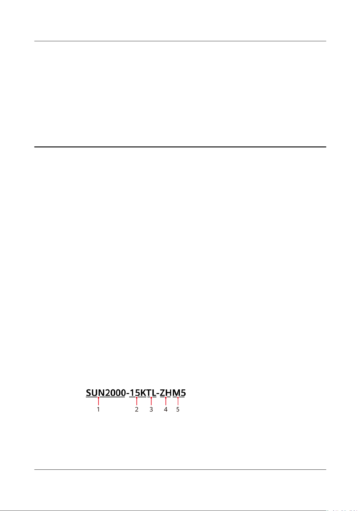
Figure 2-1 Model description (SUN2000-15KTL-ZHM5 is used as an example)
Issue 03 (2023-02-15) Copyright © Huawei Digital Power Technologies Co., Ltd. 13
Page 20
SUN2000-(12KTL-25KTL)-M5 Series
User Manual 2 Overview
Table 2-1 Model description
No. Meaning Value
1 Series name SUN2000: three-phase grid-tied PV string
inverter
2 Power level ● 12K: The rated power is 12 kW.
● 15K: The rated power is 15 kW.
● 17K: The rated power is 17 kW.
● 20K: The rated power is 20 kW.
● 25K: The rated power is 25 kW.
3 Topology TL: transformerless
4 Sales region ZH: China
5 Product code M5: product series with an input voltage level
of 1100 V DC
Supported Power Grids
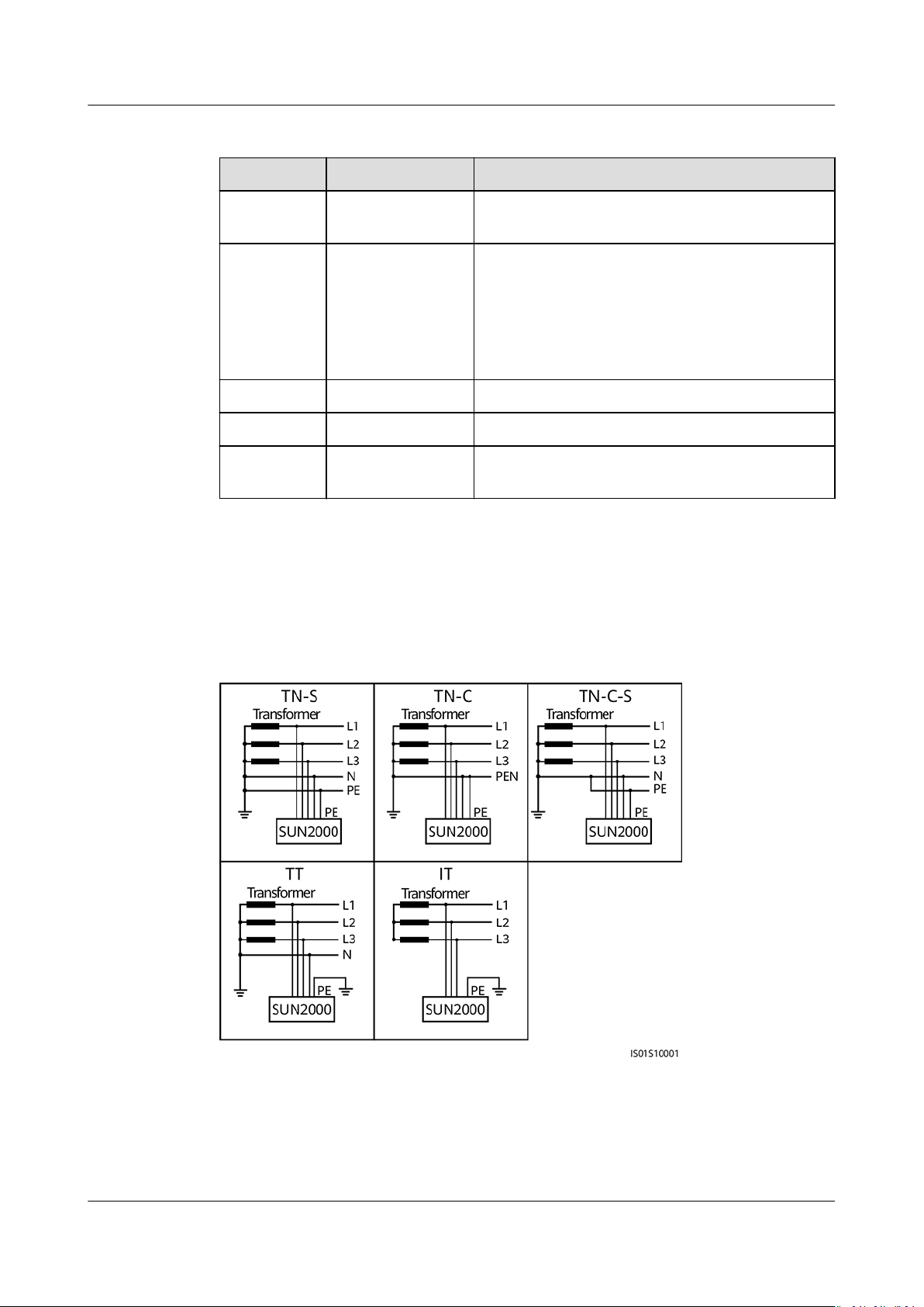
Power grid types supported by the SUN2000 include TN-S, TN-C, TN-C-S, TT, and
IT.
Figure 2-2 Supported power grids
Issue 03 (2023-02-15) Copyright © Huawei Digital Power Technologies Co., Ltd. 14
Page 21
NO TE
NO TE
NO TE
SUN2000-(12KTL-25KTL)-M5 Series
User Manual 2 Overview
● In a TT power grid, the N-PE voltage should be lower than 30 V.
● In an IT power grid, you need to set isolation settings to input not grounded, with a
transformer.
Networking Application
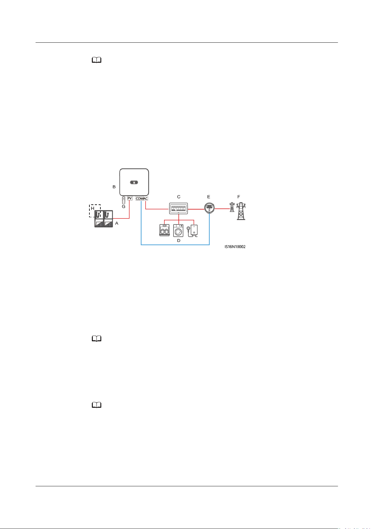
The SUN2000 applies to residential rooftop grid-tied systems and small-sized
ground grid-tied PV plants. Typically, a grid-tied system consists of PV strings, gridtied inverters, AC switches, and power distribution units.
Figure 2-3 Networking application (single inverter)
(A) PV string (B) SUN2000 (C) AC power
distribution unit
(D) Load (E) Power meter (F) Power grid
(G) Smart Dongle (H) Optimizer
For detailed operations on devices in the network, see the following guides:
SUN2000-(600W-P, 450W-P2) Smart PV Optimizer Quick Guide
SUN2000 Smart PV Optimizer User Manual
MERC-(1300W, 1100W)-P Smart PV Optimizer Quick Guide
MERC Smart PV Optimizer User Manual
● For two PV strings connected in parallel to the same MPPT circuit, the model, quantity,
orientation, and tilt angle of PV modules in the PV strings must be the same.
● The voltage of dierent MPPT circuits must be the same.
● The MPPT voltage must be greater than the lower threshold of the full-load MPPT
specied in the inverter technical data sheet. Otherwise, the inverter will be
range
derated, causing the system yield loss.
Issue 03 (2023-02-15) Copyright © Huawei Digital Power Technologies Co., Ltd. 15
Page 22
SUN2000-(12KTL-25KTL)-M5 Series
User Manual 2 Overview
2.2 Appearance
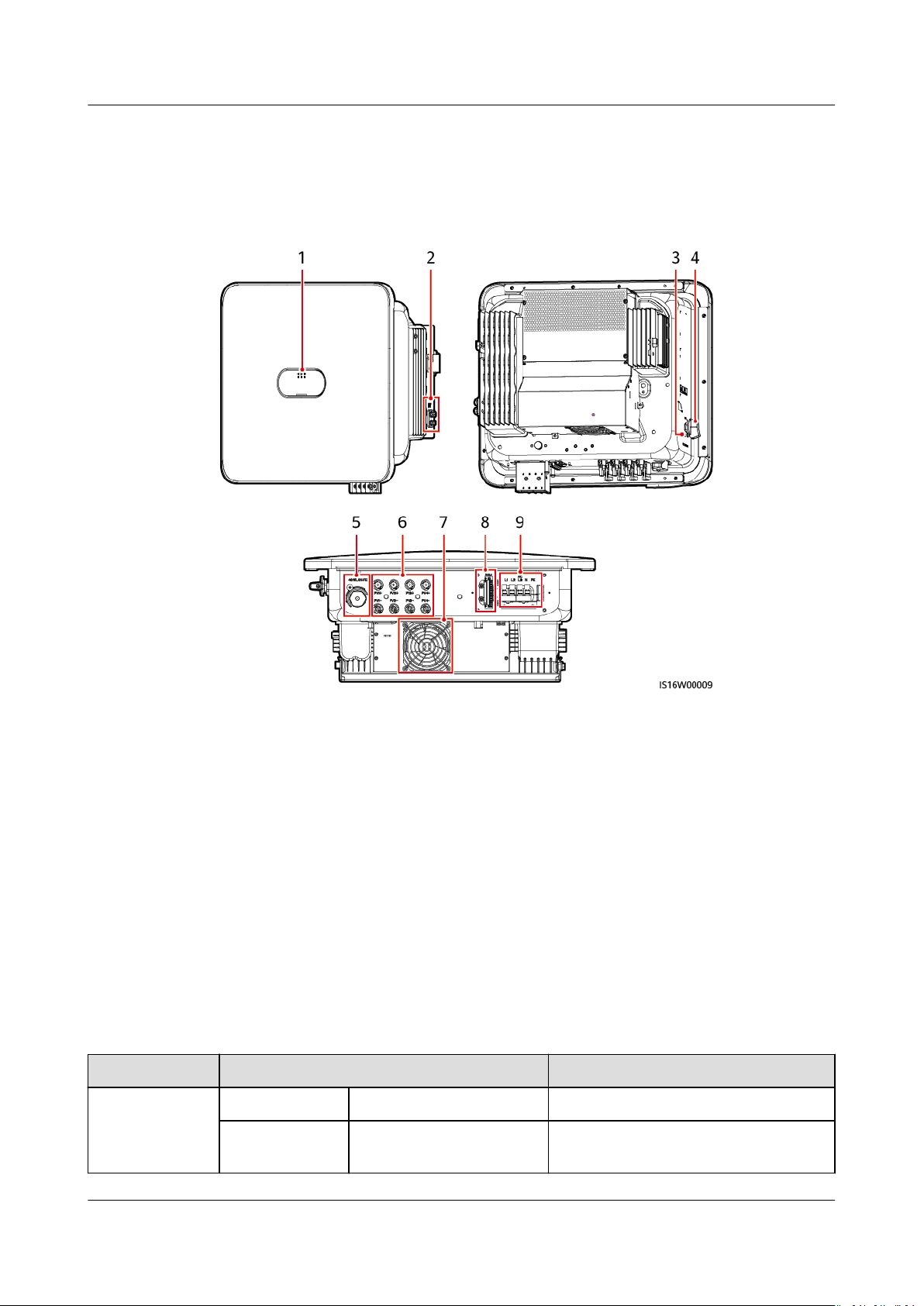
Figure 2-4 Appearance
(1) LED indicators (2) Ground screws
(3) DC switch locking screw hole
(5) Smart Dongle port (4G/WLAN-FE) (6) DC input terminals (PV1–PV4)
(7) Fan (8) Communication port (COM)
(9) AC output ports (AC)
Note [1]: For models used in Australia, the DC switch locking screw needs to be
installed according to the local standard to secure the DC switch (DC SWITCH)
and prevent incorrect startup. The DC switch locking screw is delivered with the
device.
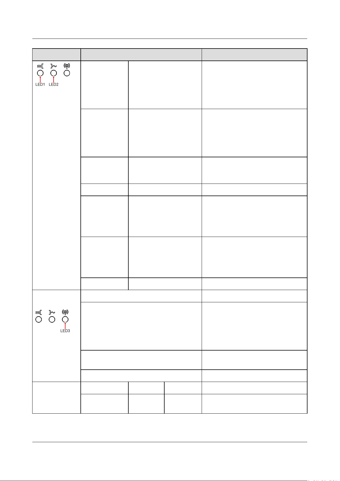
Table 2-2 LED indicator description
Category
Running
indication
Status Meaning
LED1 LED2 N/A
Steady green Steady green The SUN2000 is operating in grid-
[1]
(4) DC switch (DC SWITCH)
tied mode.
Issue 03 (2023-02-15) Copyright © Huawei Digital Power Technologies Co., Ltd. 16
Page 23
SUN2000-(12KTL-25KTL)-M5 Series
User Manual 2 Overview
Category Status Meaning
Blinking green
O The DC is on and the AC is o.
at long
intervals (on
for 1s and
then o for
1s)
Blinking green
at long
intervals (on
Blinking green at long
intervals (on for 1s and
then o for 1s)
The DC is on, the AC is on, and the
SUN2000 is not exporting power to
the power grid.
for 1s and
then o for
1s)
O Blinking green at long
The DC is o and the AC is on.
intervals (on for 1s and
then o for 1s)
O O Both the DC and AC are o.
Blinking red at
short intervals
(on for 0.2s
and then o
for 0.2s)
N/A There is a DC environmental alarm,
such as an alarm indicating that
High String Input Voltage, String
Reverse Connection, or Low
Insulation Resistance.
Communicatio
n indication
Device
replacement
indication
N/A Blinking red at short
intervals (on for 0.2s
and then o for 0.2s)
There is an AC environmental
alarm, such as an alarm indicating
Grid Undervoltage, Grid
Overvoltage, Grid Overfrequency, or
Grid Underfrequency.
Steady red Steady red Fault
LED3 N/A
Blinking green at short intervals (on for
0.2s and then o for 0.2s)
Communication is in progress.
(When a mobile phone is connected
to the SUN2000, the indicator rst
indicates that the phone is
connected to the SUN2000: blinks
green at long intervals.)
Blinking green at long intervals (on for 1s
and then o for 1s)
The mobile phone is connected to
the SUN2000.
O There is no communication.
LED1 LED2 LED3 N/A
Steady red Steady red Steady red The SUN2000 hardware is faulty.
The SUN2000 needs to be replaced.
Issue 03 (2023-02-15) Copyright © Huawei Digital Power Technologies Co., Ltd. 17
Page 24
SUN2000-(12KTL-25KTL)-M5 Series
User Manual 2 Overview
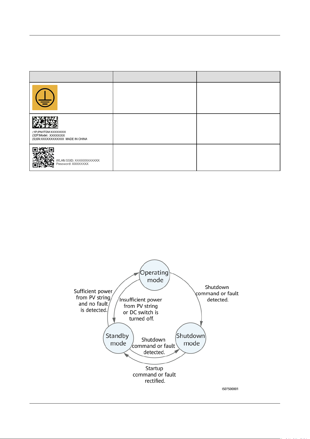
2.3 Label Description
Symbol Name Meaning
Grounding label Indicates the position for
connecting the protective
earthing (PE) cable.
Inverter serial number (SN)
label
QR code label for inverter WiFi connection
2.4 Working Principles
2.4.1 Working Modes
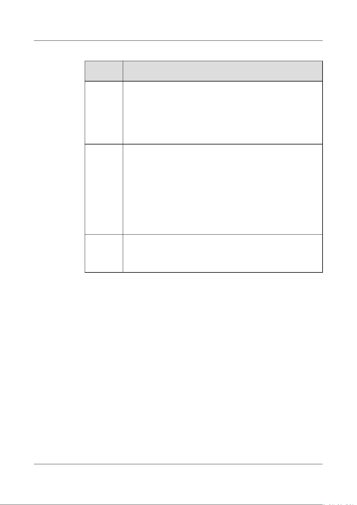
The SUN2000 can work in Standby, Operating, or Shutdown mode.
Figure 2-5 Working modes
Indicates the product SN.
Scan the QR code to connect
to the SUN2000 inverter Wi-Fi.
Issue 03 (2023-02-15) Copyright © Huawei Digital Power Technologies Co., Ltd. 18
Page 25
SUN2000-(12KTL-25KTL)-M5 Series
User Manual 2 Overview
Table 2-3 Working mode description
Working
Mode
Standby The SUN2000 enters Standby mode when the external
Operating In Operating mode:
Shutdown ● In Standby or Operating mode, the SUN2000 enters Shutdown
Description
environment does not meet the operating requirements. In
Standby mode:
● The SUN2000 continuously performs status check and enters
the Operating mode once the operating requirements are met.
● The SUN2000 enters Shutdown mode after detecting a
shutdown command or a fault after startup.
● The SUN2000 converts DC power from PV strings into AC power
and feeds the power to the power grid.
● The SUN2000 tracks the maximum power point to maximize
the PV string output.
● If the SUN2000 detects a fault or a shutdown command, it
enters the Shutdown mode.
● The SUN2000 enters Standby mode after detecting that the PV
string output power is not suitable for connecting to the power
grid for generating power.
mode after detecting a fault or shutdown command.
● In Shutdown mode, the SUN2000 enters Standby mode after
detecting a startup command or that the fault is rectied.
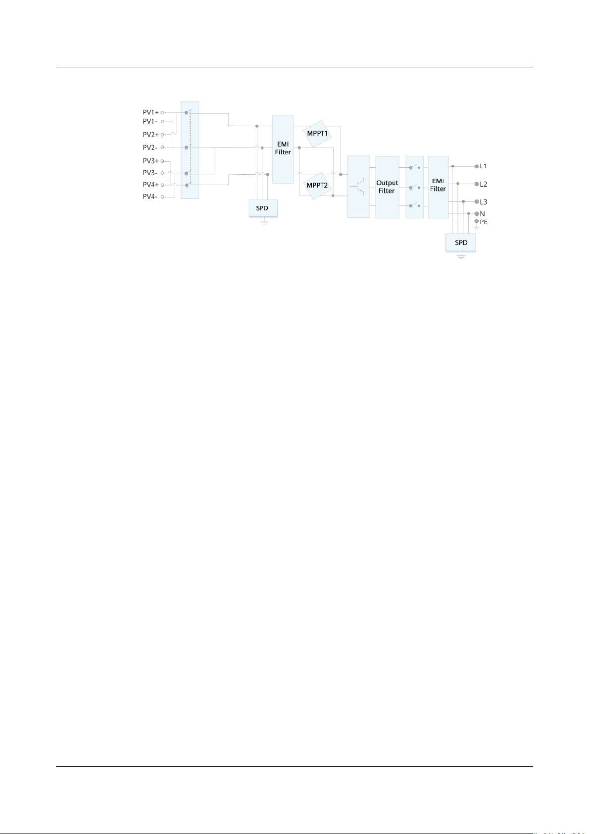
2.4.2 Circuit Diagram
The inverter connects to four PV strings and tracks the maximum power point of
the PV strings through two maximum power point tracking (MPPT) circuits. It also
converts DC power into three-phase AC power through an inverter circuit. Surge
protection is supported on both the DC and AC sides.
Issue 03 (2023-02-15) Copyright © Huawei Digital Power Technologies Co., Ltd. 19
Page 26
SUN2000-(12KTL-25KTL)-M5 Series
User Manual 2 Overview
Figure 2-6 Conceptual diagram
Issue 03 (2023-02-15) Copyright © Huawei Digital Power Technologies Co., Ltd. 20
Page 27

SUN2000-(12KTL-25KTL)-M5 Series
User Manual 3 SUN2000 Storage
3 SUN2000 Storage
The following requirements should be met if the SUN2000 is not put into use
directly:
● Do not unpack the SUN2000.
● Keep the storage temperature at –40°C to +70°C and the humidity at 5%–
95% RH.
● Store the SUN2000 in a clean and dry place and protect it from dust and
water vapor corrosion.
● A maximum of six SUN2000s can be stacked. To avoid personal injury or
device damage, stack SUN2000s with caution to prevent them from falling
over.
● During the storage period, check the SUN2000 periodically (recommended:
every three months). If any rodent bites are found on the packing materials,
replace the packing materials immediately.
● If the SUN2000 has been stored for more than two years, it must be checked
and tested by professionals before being put into use.
Issue 03 (2023-02-15) Copyright © Huawei Digital Power Technologies Co., Ltd. 21
Page 28
NO TE
NO TICE
NO TE
SUN2000-(12KTL-25KTL)-M5 Series
User Manual 4 Installation
4 Installation
4.1 Checking Before Installation
Outer Packing Materials
Before unpacking the inverter, check the outer packing materials for damage, such
as holes and cracks, and check the inverter model. If any damage is found or the
inverter model is not what you requested, do not unpack the package and contact
your supplier as soon as possible.
You are advised to remove the packing materials within 24 hours before installing the
inverter.
Package Contents
● After placing the equipment in the installation position, unpack it with care to
prevent scratches. Keep the equipment stable during unpacking.
After unpacking the inverter, check that the contents are intact and complete. If
any damage is found or any component is missing, contact your supplier.
For details about the number of contents, see the
Issue 03 (2023-02-15) Copyright © Huawei Digital Power Technologies Co., Ltd. 22
Packing List
in the packing case.
Page 29
SUN2000-(12KTL-25KTL)-M5 Series
User Manual 4 Installation
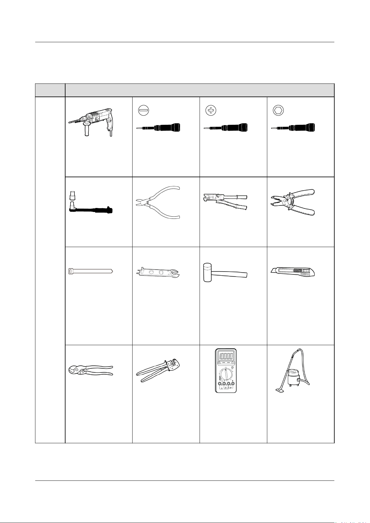
4.2 Tools
Type Tool
Installa
tion
Tools
Hammer drill
Drill bit: Φ8 mm
and Φ6 mm
Insulated torque
socket wrench
Cable tie
Flat-head insulated
torque screwdriver
Diagonal pliers
Removal wrench
Model: PV-MS-HZ
Open-end Wrench;
manufacturer:
Staubli
Phillips insulated
torque screwdriver
Hydraulic pliers
Rubber mallet Utility knife
Hex insulated
torque screwdriver
Wire stripper
Cable cutter
Issue 03 (2023-02-15) Copyright © Huawei Digital Power Technologies Co., Ltd. 23
Crimping tool
Model: PVCZM-22100/19100;
manufacturer:
Staubli
Multimeter
DC voltage
measurement range
≥ 1100 V DC
Vacuum cleaner
Page 30
SUN2000-(12KTL-25KTL)-M5 Series
User Manual 4 Installation
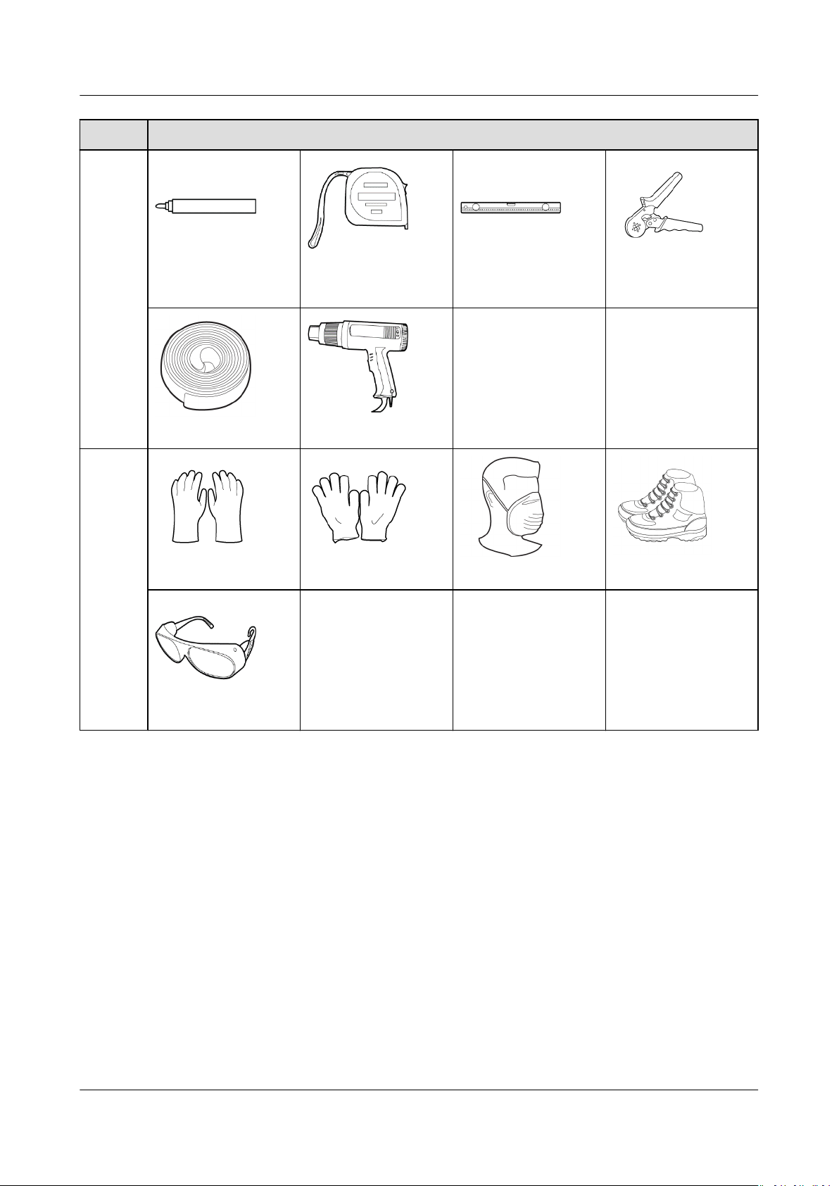
Type Tool
PPE
Marker Measuring tape Bubble or digital
level
- -
Heat shrink tubing Heat gun
Insulated gloves Protective gloves Dust mask
- - -
Cord end terminal
crimper
Safety shoes
Safety goggles
4.3 Determining the Installation Position
4.3.1 Environment Requirements
Basic Requirements
● The inverter is protected to IP66 and can be installed indoors or outdoors.
● Do not install the inverter in an easily accessible place because its enclosure
and heat sinks generate high temperature during operation.
● Do not install the inverter in noise-sensitive areas.
● Do not install the inverter in areas with
● Do not install the inverter in a place within children's reach.
Issue 03 (2023-02-15) Copyright © Huawei Digital Power Technologies Co., Ltd. 24
ammable or explosive materials.
Page 31
SUN2000-(12KTL-25KTL)-M5 Series
User Manual 4 Installation
● Do not install the inverter outdoors in salt areas because it will be corroded
there and may cause re. A salt area refers to a region within 500 m of the
coast or prone to sea breeze. Regions prone to sea breeze vary with weather
conditions (such as typhoons and monsoons) or terrains (such as dams and
hills).
● The inverter should be installed in a well-ventilated environment to ensure
good heat dissipation.
● You are advised to install the inverter in a sheltered area, or with an awning
over it.
Mounting Structure Requirements
● The mounting structure where the inverter is installed must be
● Do not install the inverter on ammable building materials.
● The inverter is heavy. Ensure that the installation surface is solid enough to
bear the weight.
● In residential areas, do not install the inverter on drywalls or walls made of
similar materials which have a weak sound insulation performance because
the noise generated by the inverter is noticeable.
4.3.2 Space Requirements
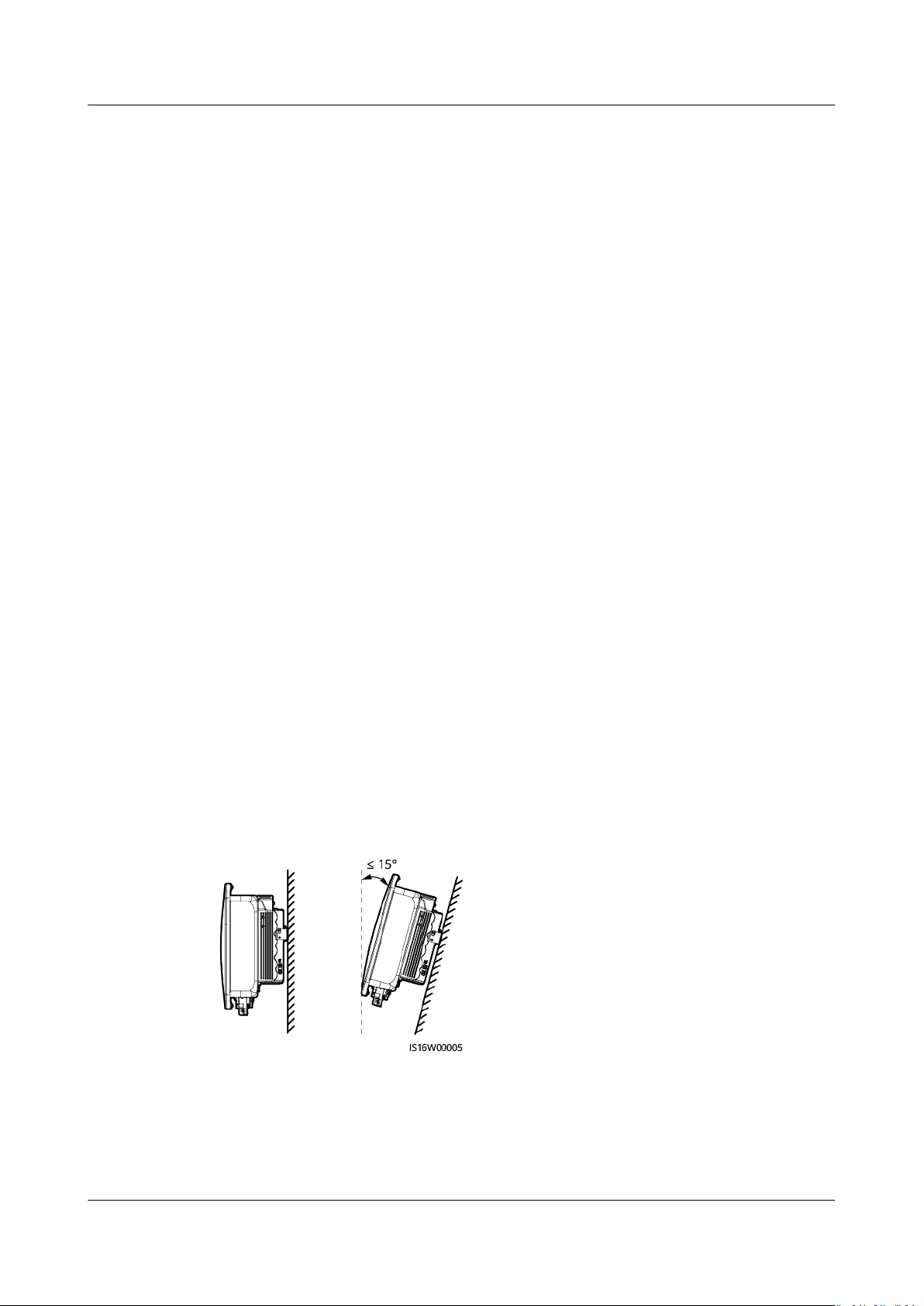
Installation Angle Requirements
The inverter can be wall-mounted or support-mounted. The installation angle
requirements are as follows:
● Install the inverter vertically or at a maximum back tilt of 15 degrees to
facilitate heat dissipation.
● Do not install the inverter at forward tilted, excessive back tilted, side tilted,
horizontal, or upside down positions.
Figure 4-1 Installation angle
reproof.
Clearance Requirements
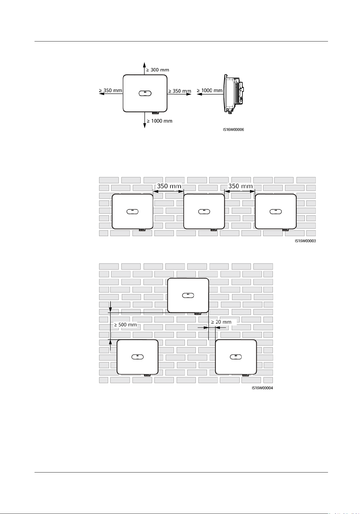
● Reserve enough clearance around the inverter to ensure
installation and heat dissipation.
Issue 03 (2023-02-15) Copyright © Huawei Digital Power Technologies Co., Ltd. 25
sucient space for
Page 32
SUN2000-(12KTL-25KTL)-M5 Series
User Manual 4 Installation
Figure 4-2 Clearance
● When installing multiple inverters, install them in horizontal mode if sucient
space is available and install them in triangle mode if no sucient space is
available. Stacked installation is not recommended.
Figure 4-3 Horizontal installation (recommended)
Figure 4-4 Triangle installation (recommended)
4.4 Moving an Inverter
Procedure
Step 1 Two persons are required to move the inverter with one person on both sides. Lift
the inverter from the packing case and move it to the
position.
Issue 03 (2023-02-15) Copyright © Huawei Digital Power Technologies Co., Ltd. 26
specied installation
Page 33
CA UTION
D ANGER
NO TICE
NO TE
SUN2000-(12KTL-25KTL)-M5 Series
User Manual 4 Installation
● Move the inverter with care to prevent device damage and personal injury.
● Do not hold the wiring terminals and ports at the bottom. Do not place the
inverter with the wiring terminals and ports touching the ground or other
supporting surface.
● When you need to temporally place the inverter on the ground, use protection
material such as foam and paper underneath to prevent damage to its
enclosure.
----End
4.5 Installing an Inverter
Installation Precautions
Avoid drilling holes into the water pipes or power cables buried in the wall.
● To avoid inhaling dust and to prevent dust from falling into your eyes, ensure
that safety goggles and a dust mask are worn when drilling holes.
● Use a vacuum cleaner to clean up dust in and around the holes, and measure
the spacing. If the holes are inaccurately positioned, drill the holes again.
● Level the top of the expansion sleeve with the concrete wall after removing the
bolt, spring washer, and
at washer. Otherwise, the mounting bracket will not
be securely installed on the concrete wall.
● Loosen the nuts,
at washers, and spring washers of the two expansion bolts
below.
● M6x60 expansion bolts are delivered with the inverter. If the length and quantity of the
bolts do not meet installation requirements, prepare M6 stainless steel expansion bolts
by yourself.
● The expansion bolts delivered with the inverter are mainly used for solid concrete walls.
For other types of walls, prepare bolts by yourself and ensure that the wall meets the
load bearing requirements of the inverter.
● For support-mounting, prepare M6 stainless bolt assemblies (including at washers,
spring washers, and M6 bolts) with appropriate lengths as well as corresponding at
washers and nuts based on the support specications.
Issue 03 (2023-02-15) Copyright © Huawei Digital Power Technologies Co., Ltd. 27
Page 34
SUN2000-(12KTL-25KTL)-M5 Series
User Manual 4 Installation
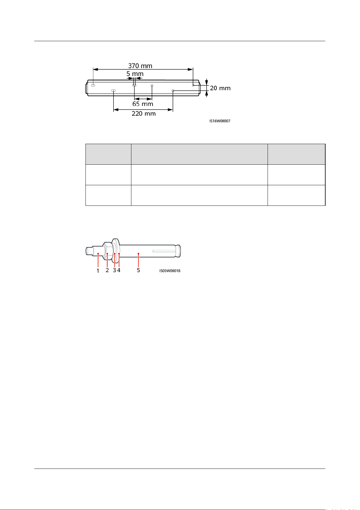
Figure 4-5 Mounting bracket dimensions
Table 4-1 Installation modes
Installation
Mode
Wallmounting
Supportmounting
Figure 4-6 Expansion bolt composition
(1) Bolt
(4) Flat washer (5) Expansion sleeve
Screw Specications Description
M6x60 stainless steel expansion bolt Delivered with
M6 bolt assembly Prepared by the
(2) Nut (3) Spring washer
the product
customer
Procedure
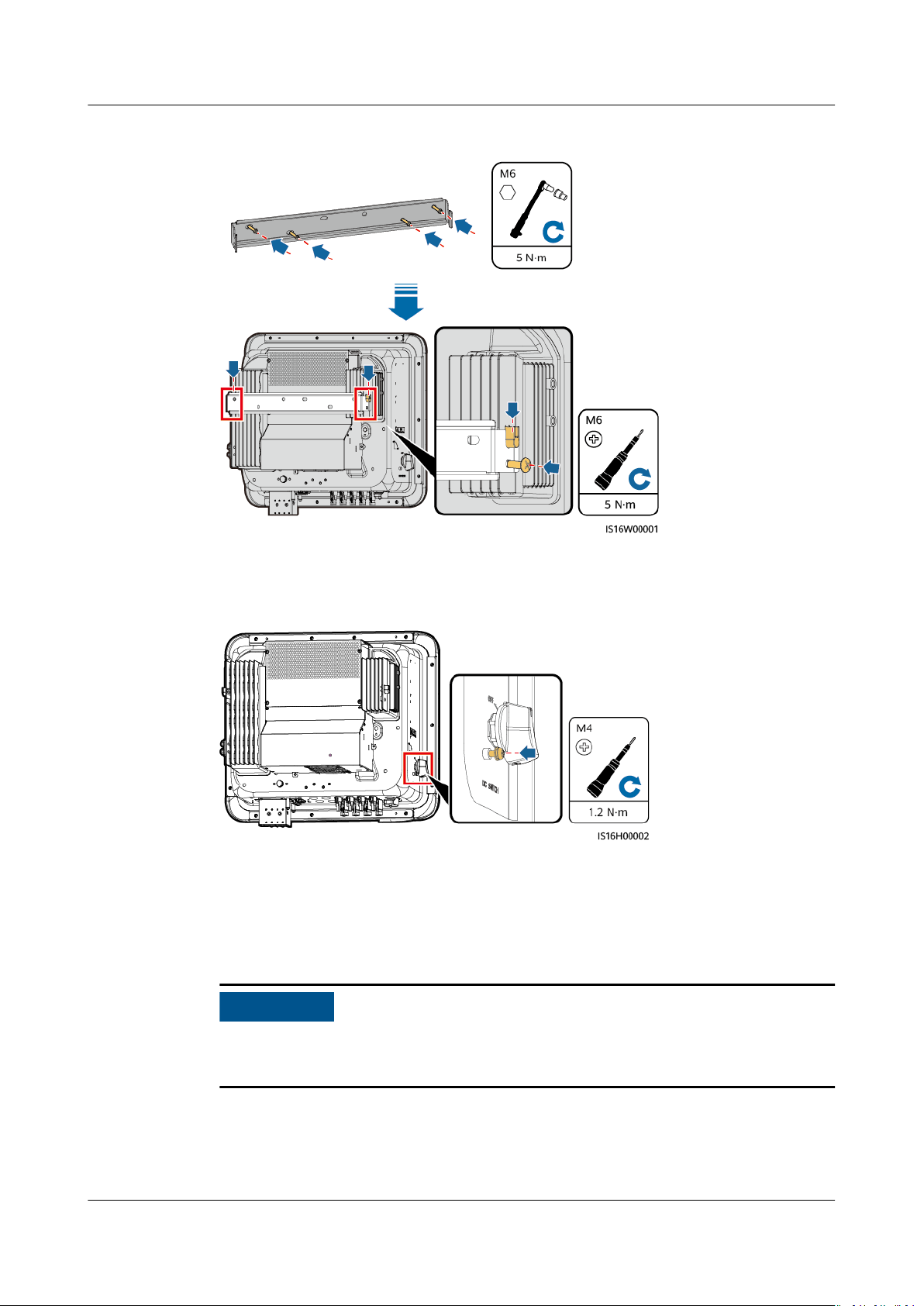
Step 1 Install the mounting bracket.
Step 2 Mount the inverter on the mounting bracket and install screws.
Issue 03 (2023-02-15) Copyright © Huawei Digital Power Technologies Co., Ltd. 28
Page 35
NO TICE
SUN2000-(12KTL-25KTL)-M5 Series
User Manual 4 Installation
Figure 4-7 Installing an Inverter
Step 3 (Optional) Install the locking screw for the DC switch.
Figure 4-8 Installing the locking screw for the DC switch
----End
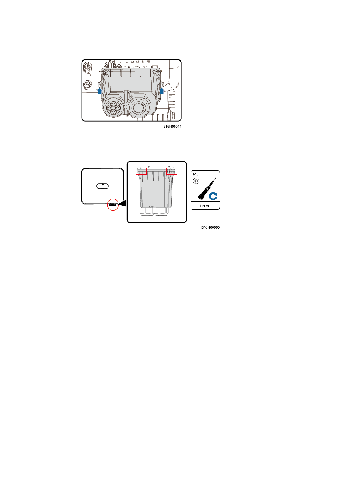
4.6 (Optional) Installing a Junction Box
If you do not connect cables immediately after securing the inverter, install a
junction box. Otherwise, the protection level of the inverter will be aected.
Step 1 Align the pin holes at both ends of the junction box with the positioning pins on
the inverter enclosure to ensure that the screw holes on the junction box are
aligned.
Issue 03 (2023-02-15) Copyright © Huawei Digital Power Technologies Co., Ltd. 29
Page 36
SUN2000-(12KTL-25KTL)-M5 Series
User Manual 4 Installation
Figure 4-9 Aligning positioning pins
Step 2 Install the junction box.
Figure 4-10 Installing a junction box
----End
Issue 03 (2023-02-15) Copyright © Huawei Digital Power Technologies Co., Ltd. 30
Page 37
D ANGER
D ANGER
WARNING
SUN2000-(12KTL-25KTL)-M5 Series
User Manual 5 Electrical Connections
5 Electrical Connections
5.1 Precautions
When exposed to sunlight, the PV arrays supply DC voltage to the SUN2000.
Before connecting cables, ensure that the two DC switches on the SUN2000 are
OFF. Otherwise, the high voltage of the SUN2000 may result in electric shocks.
● The site must be equipped with qualied re suppression facilities, such as re
sand and carbon dioxide re extinguishers.
● Wear insulated gloves and use insulated tools to prevent electric shocks or
short circuits.
● The equipment damage caused by incorrect cable connections is beyond the
warranty scope.
● Only
● Wear proper PPE at all time when terminating cables.
● To prevent poor cable connection due to overstress, it is recommended that the
certied electrician can perform electrical terminations.
cables be bent and reserved, and then connected to the appropriate ports.
Issue 03 (2023-02-15) Copyright © Huawei Digital Power Technologies Co., Ltd. 31
Page 38
CA UTION
NO TE
SUN2000-(12KTL-25KTL)-M5 Series
User Manual 5 Electrical Connections
● Stay away from the equipment when preparing cables to prevent cable scraps
from entering the equipment. Cable scraps may cause sparks and result in
personal injury and equipment damage.
● When routing PV cables, the positive and negative PV string cables should be
routed in
dierent pipes to prevent cable damage and short circuits caused by
improper operations during construction.
The cable colors shown in the electrical connection diagrams provided in this chapter are
for reference only. Select cables in accordance with local cable specications (green-andyellow cables are only used for grounding).
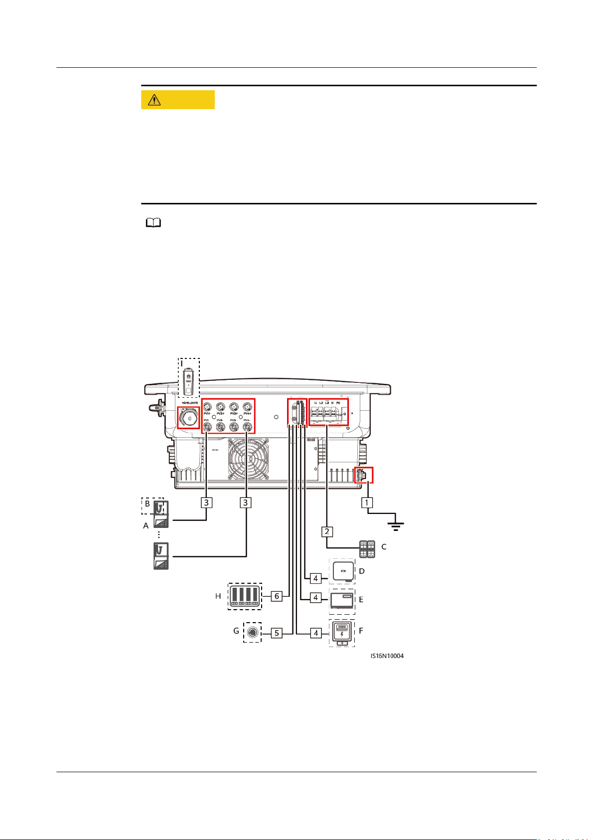
5.2 Preparing Cables
Figure 5-1 SUN2000 cable connections (Components in the dashed boxes are
optional.)
Issue 03 (2023-02-15) Copyright © Huawei Digital Power Technologies Co., Ltd. 32
Page 39
SUN2000-(12KTL-25KTL)-M5 Series
User Manual 5 Electrical Connections
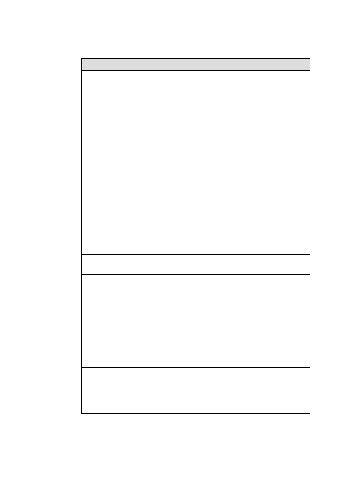
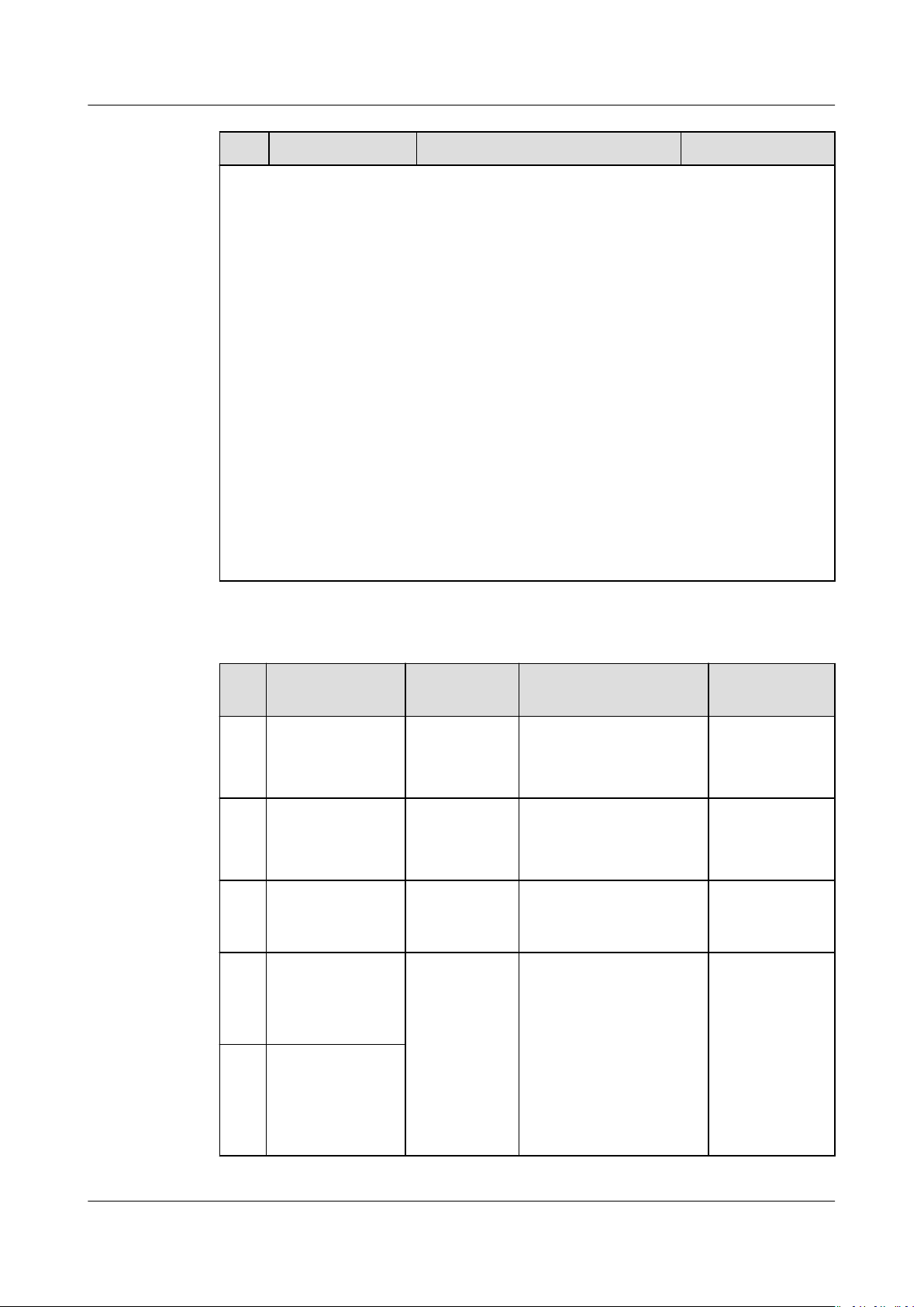
Table 5-1 Component description
No. Component Description Source
A PV module ● A PV string consists of PV
modules connected in series.
● The inverter supports the
input from four PV strings.
B Smart PV
optimizer
The SUN2000-(600W-P, 450WP2) and MERC-(1300W, 1100W)-
P are supported.
[3]
C AC switch To ensure that the inverter can
be safely disconnected from the
power grid when an exception
occurs, connect an AC switch to
the AC side of the inverter. Select
an appropriate AC switch in
accordance with local industry
standards and regulations.
Huawei recommends the
following switch
specications:
Recommended: three-phase AC
circuit breaker, rated voltage ≥
415 V AC, rated current:
● 12KTL–20KTL: 40 A
● 25KTL: 50 A or 63 A
Prepared by the
customer
Purchased from
the Company
Prepared by the
customer
D SUN2000 Select a proper model as
required.
E SmartLogger Select a proper model as
required.
F
Power meter
[1]
Recommended models:
DTSU666-H, DTSU666-HW,
YDS60-80 and YDS60-C24
G Rapid shutdown
switch
H Power grid
scheduling device
Select a proper model as
required.
Select the devices that meet the
power grid scheduling
requirements.
I
Smart Dongle
[2]
Supported models:
● WLAN-FE Smart Dongle:
SDongleA-05
● 4G Smart Dongle:
SDongleA-03, SDongleB-06
Purchased from
the Company
Purchased from
the Company
Purchased from
the Company
[4]
Prepared by the
customer
Provided by the
local power grid
company
Purchased from
the Company
Issue 03 (2023-02-15) Copyright © Huawei Digital Power Technologies Co., Ltd. 33
Page 40
SUN2000-(12KTL-25KTL)-M5 Series
User Manual 5 Electrical Connections
No. Component Description Source
Note [1]: For details about meter operations, see
DTSU666-HW Smart Power
Sensor Quick Guide, DTSU666-H 100 A and 250 A Smart Power Sensor User
Manual, YDS60-80 Smart Power Sensor Quick Guide, and YDS60-C24 Smart
Power Sensor Quick Guide
.
Note [2]: For details about how to use the WLAN-FE Smart Dongle
SDongleA-05, see
SDongleA-05 Smart Dongle Quick Guide (WLAN-FE)
details about how to use the 4G Smart Dongle SDongleA-03, see
Quick Guide (4G)
SDongleB-06, see
. For details about how to use the Smart Dongle
SDongleB-06 Smart Dongle Quick Guide (4G)
SDongleA-03
. You can
. For
obtain the quick guides at https://support.huawei.com/enterprise by
searching for the Smart Dongle model.
Note [3]: The SUN2000-(600W-P, 450W-P2) cannot be used together with the
MERC-(1300W, 1100W)-P.
Note [4]:
● SUN2000MB V200R022C10SPC101(B044) and later versions can connect to
the YDS60-C24 meters.
● Ensure that the baud rates of the DTSU666-H and YDS60-C24 meters are set
to the default values. If they are changed, meters may go
oine, generate
alarms, or aect the inverter output power.
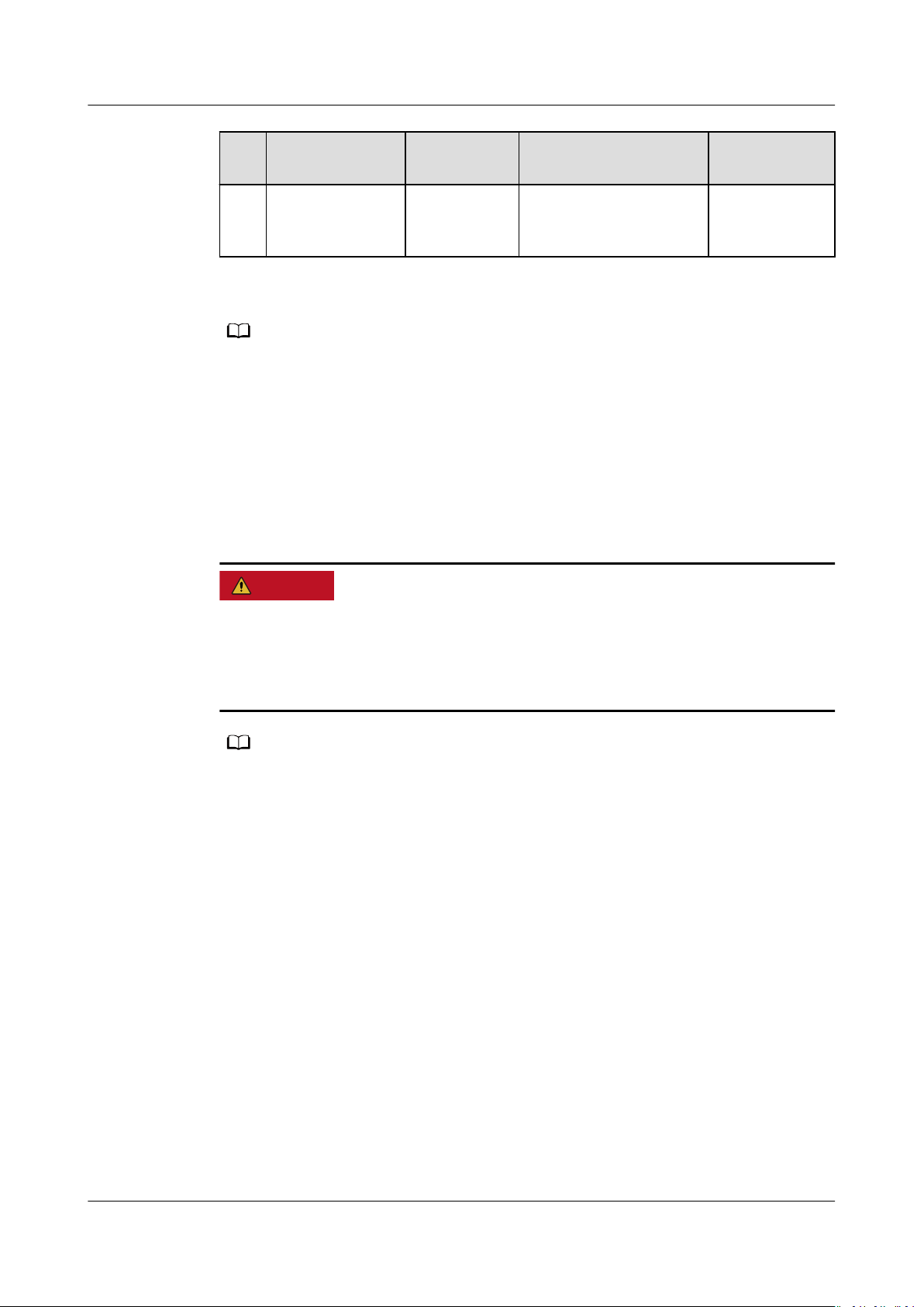
Table 5-2 Cable description
No.
Name Type Conductor Cross-
1 PE cable Single-core
outdoor
copper cable
2 AC output
power cable
3 DC input power
cable
Outdoor
copper cable
Common
outdoor PV
cable
4 (Optional)
RS485
communications
cable
Two-core
outdoor
shielded
twisted pair
cable
5 (Optional)
Signal cable to
the rapid
shutdown
switch
Sectional Area
12KTL: ≥ 6 mm
2
15KTL–25KTL: ≥ 10
2
mm
12KTL: 6–16 mm
2
15KTL–25KTL: 10–16
2
mm
4–6 mm
0.2–1 mm
2
2
(recommended: 0.5
mm2)
Outer
Diameter
-
11–26 mm
5.5–9 mm
4–11 mm
Issue 03 (2023-02-15) Copyright © Huawei Digital Power Technologies Co., Ltd. 34
Page 41
NO TE
D ANGER
NO TE
SUN2000-(12KTL-25KTL)-M5 Series
User Manual 5 Electrical Connections
No. Name Type Conductor Cross-
6 (Optional) Grid
scheduling
signal cable
Five-core
outdoor
cable
● The minimum cable diameter must meet local standards.
● The factors that
mode, ambient temperature, and maximum expected line loss.
aect cable selection include the rated current, cable type, routing
5.3 Connecting the Ground Cable
Precautions
Sectional Area
Outer
Diameter
● Ensure that the PE cable is securely connected. Otherwise, electric shocks may
occur.
● Do not connect the neutral wire to the enclosure as a PE cable. Otherwise,
electric shocks may occur.
● The PE point at the AC output port is used only as a PE equipotential point, and cannot
substitute for the PE point on the enclosure.
● It is recommended that silicone grease or paint be used around the ground terminal
after the PE cable is connected.
Additional Information
The inverter provides the grounding detection function. This function is used to
check whether the inverter is properly grounded before the inverter starts, or
check whether the inverter ground cable is disconnected when the inverter is
running. This function is used to check whether the inverter is properly grounded
under limited conditions. To ensure the safe operation of the inverter, properly
ground the inverter according to the connection requirements of the PE cable. For
some power grid types, if the output side of the inverter is connected to an
isolation transformer, ensure that the inverter is properly grounded and then
disable Grounding abnormal shutdown so that the inverter can run properly.
● According to IEC 62109, to ensure the safe operation of the inverter in the
case of PE cable damage or disconnection, properly connect the PE cable of
the inverter and ensure that it meets at least one of the following
requirements before the grounding detection function becomes invalid.
Issue 03 (2023-02-15) Copyright © Huawei Digital Power Technologies Co., Ltd. 35
Page 42
NO TICE
SUN2000-(12KTL-25KTL)-M5 Series
User Manual 5 Electrical Connections
– If the PE terminal of the AC connector is not connected, the PE cable on
the enclosure must be a single-core outdoor copper cable with a crosssectional area of at least 10 mm2.
– Use cables with the same diameter as the AC output power cable and
ground the PE terminal on the AC connector and the ground screws on
the enclosure.
● In some countries and regions, the inverter must have additional ground
cables. In this case, use cables with the same diameter as the AC output
power cable and ground the PE terminal on the AC connector and the ground
screws on the enclosure.
Procedure
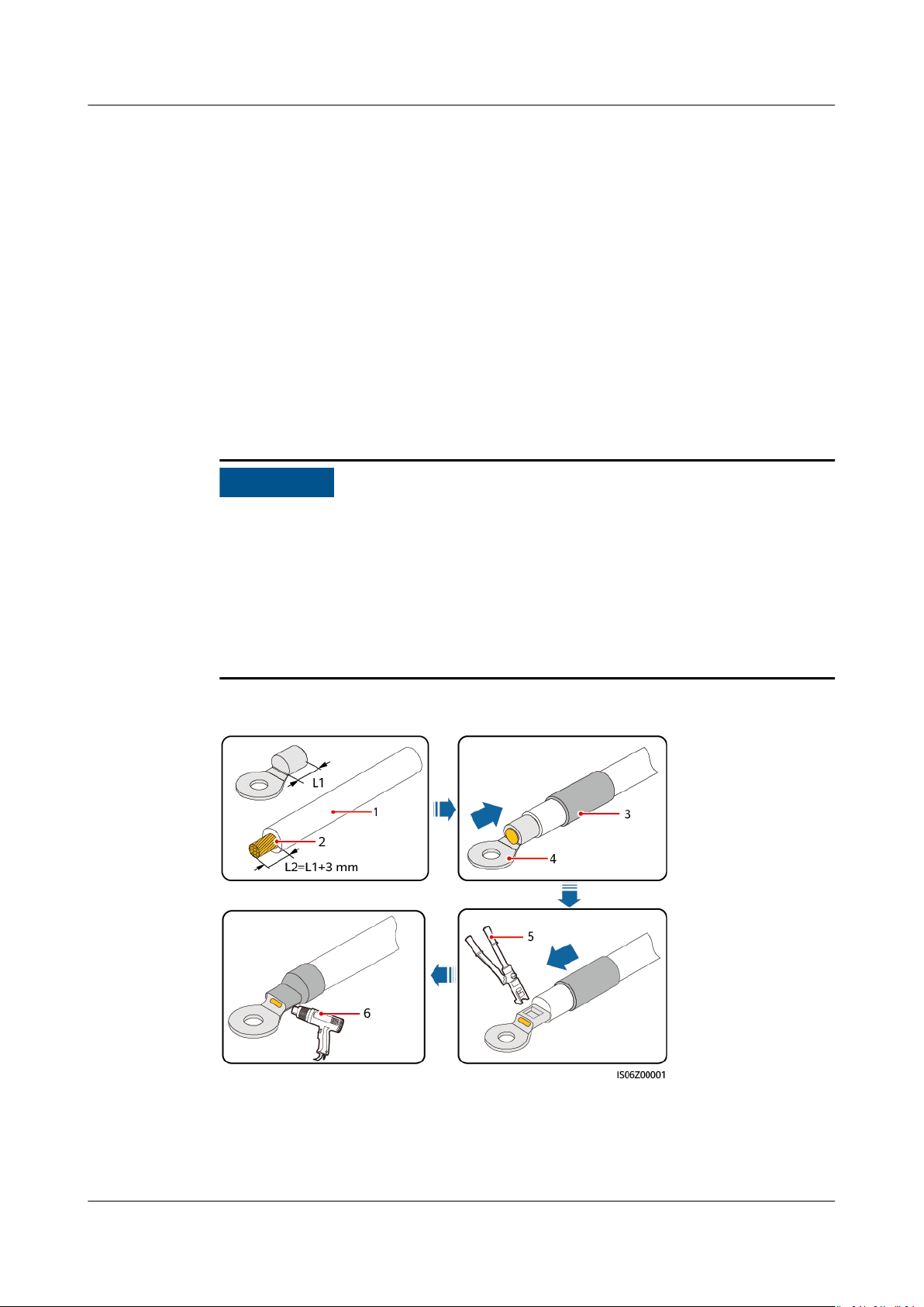
Step 1 Crimp an OT terminal.
● Avoid scratching the core wire when stripping a cable.
● The cavity formed after the conductor crimp strip of the OT terminal is crimped
must wrap the core wires completely. The core wires must contact the OT
terminal closely.
● Wrap the wire crimping area with heat-shrink tubing or insulation tape. The
heat-shrink tubing is used as an example.
● Use a heat gun carefully to avoid heat damage to the equipment.
Figure 5-2 Crimping an OT terminal
(1) Cable
(4) OT terminal (5) Crimping tool (6) Heat gun
(2) Core wire (3) Heat-shrink tubing
Issue 03 (2023-02-15) Copyright © Huawei Digital Power Technologies Co., Ltd. 36
Page 43
D ANGER
SUN2000-(12KTL-25KTL)-M5 Series
User Manual 5 Electrical Connections
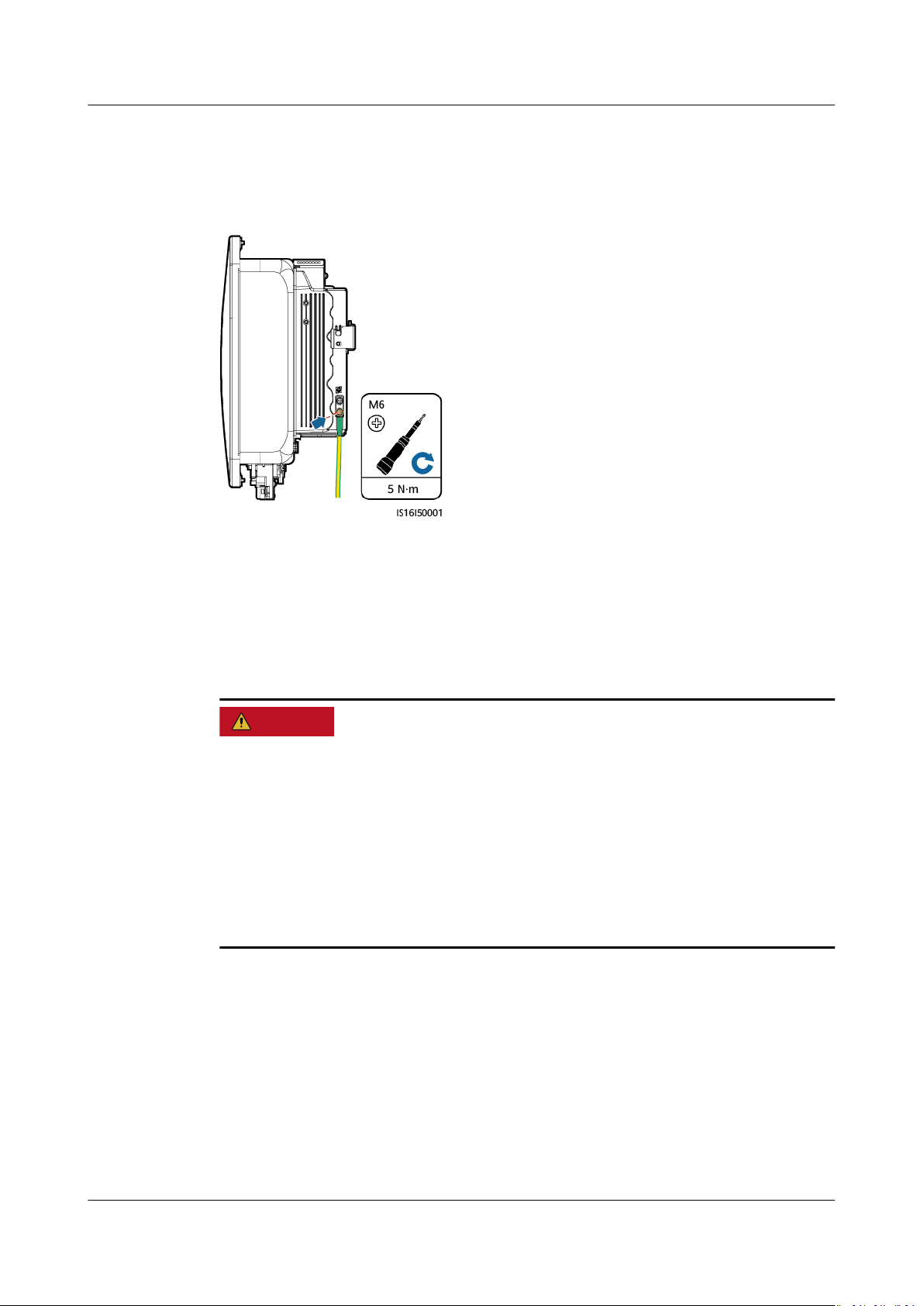
Step 2 Connect the PE cable.
Figure 5-3 Connecting a PE cable
----End
5.4 Installing DC Input Power Cables
Precautions
● Before connecting the DC input power cable, ensure that the DC voltage is
within the safe range (lower than 60 V DC) and that the inverter DC SWITCH is
OFF. Failing to do so may result in electric shocks.
● When the inverter is operating, it is not allowed to work on the DC input power
cables, such as connecting or disconnecting a PV string or a PV module in a PV
string. Otherwise, electric shocks may occur.
● If no PV string connects to a DC input terminal of the inverter, do not remove
the watertight cap from the DC input terminals. Otherwise, the protection level
of the inverter will be
aected.
Issue 03 (2023-02-15) Copyright © Huawei Digital Power Technologies Co., Ltd. 37
Page 44
WARNING
NO TICE
SUN2000-(12KTL-25KTL)-M5 Series
User Manual 5 Electrical Connections
Ensure that the following conditions are met. Otherwise, the inverter may be
damaged, or even a re may occur.
● PV modules connected in series in each PV string are of the same specications.
● The maximum open-circuit voltage of each PV string must be less than or
equal to 1100 V DC.
● The maximum short-circuit current of each PV string must be less than or equal
to 20 A.
● PV strings must be connected in the correct polarity. The positive and negative
terminals of a PV string connect to the corresponding positive and negative DC
input terminals of the inverter, respectively.
● If the DC input power cables are reversely connected, do not operate DC
SWITCH or the positive and negative connectors immediately. Wait until the
night when solar irradiance declines and the PV string current drops to below
0.5 A. Then set DC SWITCH to OFF, remove the positive and negative
connectors, and connect the DC input power cables correctly.
● The output of the PV strings connected to the inverter cannot be grounded.
Ensure that the PV output is well insulated to ground.
● PV modules and optimizers in the PV strings connecting to the same MPPT
must be of the same model and quantity.
● If power cables are not properly installed or routed during the installation of PV
strings and the inverter, the positive or negative terminals of PV strings may be
short-circuited to ground. In this case, an AC or DC short circuit may occur and
damage the inverter. The resulting device damage is not covered under any
warranty.
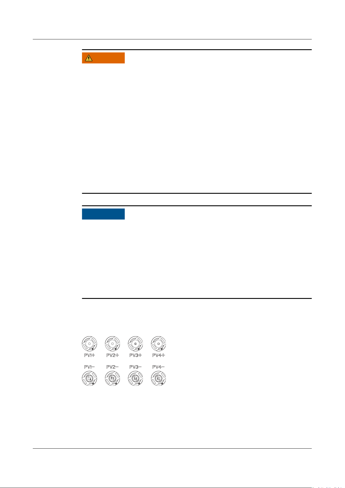
Terminal Description
Figure 5-4 DC input terminals
Issue 03 (2023-02-15) Copyright © Huawei Digital Power Technologies Co., Ltd. 38
Page 45
WARNING
NO TICE
NO TE
CA UTION
SUN2000-(12KTL-25KTL)-M5 Series
User Manual 5 Electrical Connections
Procedure
Before inserting the positive and negative connectors into the positive and
negative DC input terminals of the inverter, ensure that DC SWITCH is set to OFF.
● Cables with high rigidity, such as armored cables, are not recommended as DC
input power cables, because poor contact may be caused by the bending of the
cables.
● Before assembling DC connectors, label the cable polarity correctly to ensure
correct cable connections.
● After crimping the positive and negative metal terminals, pull back the DC
input power cables to ensure that they are connected securely.
● Insert the crimped metal terminals of the positive and negative power cables
into the appropriate positive and negative connectors. Then pull back the DC
input power cables to ensure that they are connected securely.
● If a DC input power cable is reversely connected and DC SWITCH is set to ON,
do not operate on DC SWITCH or the positive and negative connectors
immediately. Otherwise, the device may be damaged. The resulting device
damage is not covered under any warranty. Wait until the night when solar
irradiance declines and the PV string current drops to below 0.5 A. Then set DC
SWITCH to OFF, remove the positive and negative connectors, and connect DC
input power cable correctly.
● The DC voltage measurement range of the multimeter must be at least 1100 V. If the
voltage is a negative value, the DC input polarity is incorrect. Correct the cable
connection. If the voltage is greater than 1100 V DC, too many PV modules are
connected in the same string.
● If PV strings are congured with optimizers, check the cable polarity by referring to the
Smart PV Optimizer Quick Guide
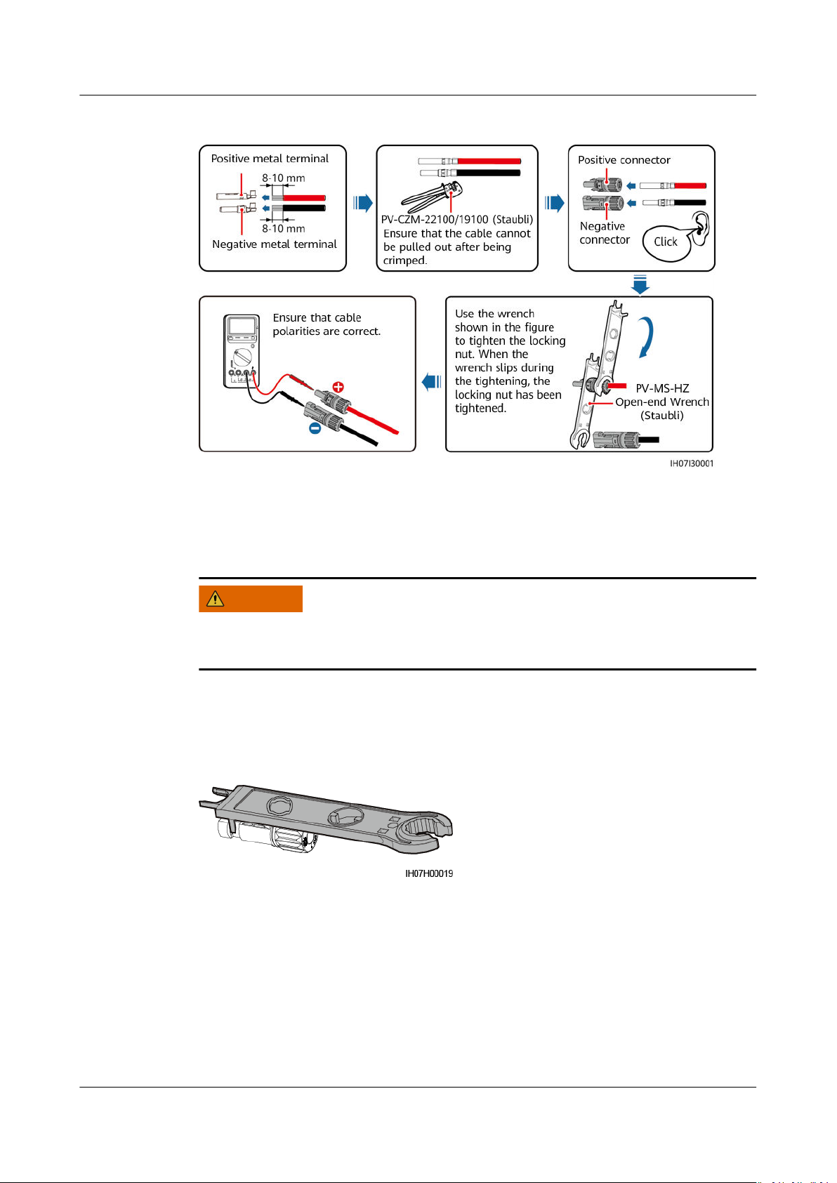
Step 1 Install the DC input power cables.
Re-congure the PV modules.
.
Use the Staubli MC4 positive and negative metal terminals and DC connectors
delivered with the inverter. Using incompatible positive and negative metal
terminals and DC connectors may result in serious consequences. The resulting
device damage is not covered under any warranty.
Issue 03 (2023-02-15) Copyright © Huawei Digital Power Technologies Co., Ltd. 39
Page 46
WARNING
SUN2000-(12KTL-25KTL)-M5 Series
User Manual 5 Electrical Connections
Figure 5-5 Assembling DC connectors
----End
Removing DC Connectors
Before removing the positive and negative connectors, ensure that DC SWITCH is
set to OFF and that the current is less than 0.5 A.
To remove the positive and negative connectors from the inverter, insert an openend wrench into the bayonet and press the wrench with force. Then remove the
DC connectors with caution.
Figure 5-6 Removing a DC Connector
5.5 Installing AC Output Power Cables and Signal Cables
Precautions
Issue 03 (2023-02-15) Copyright © Huawei Digital Power Technologies Co., Ltd. 40
It is recommended that a three-phase AC switch be installed on the AC side of the
inverter. To ensure that the inverter can safely disconnect itself from the power
Page 47
WARNING
CA UTION
NO TICE
NO TICE
SUN2000-(12KTL-25KTL)-M5 Series
User Manual 5 Electrical Connections
grid when an exception occurs, select a proper overcurrent protection device in
compliance with local power distribution regulations.
● Do not connect loads between an inverter and an AC switch that directly
connects to the inverter. Otherwise, the switch may trip by mistake.
● If an AC switch is used with
or the Company's recommendations, the switch may fail to turn
specications beyond local standards, regulations,
o in a timely
manner in case of exceptions, causing serious faults.
Each inverter must be equipped with an AC output switch. Multiple inverters
cannot connect to the same AC switch.
The inverter is installed with an integrated monitoring unit for the residual
current. When the inverter detects that the residual current exceeds the permitted
value, it disconnects from the power grid quickly.
● If the external AC switch has residual current protection, its rated leakage
tripping current must be greater than or equal to 300 mA.
● If multiple inverters are connected to the master leakage protection device
through their AC switches, the rated leakage tripping current of the device
must be greater than or equal to the number of inverters x 300 mA.
● The AC switch cannot be a knife switch.
COM Port Pin Denitions
● When laying out signal cables, separate them from power cables and keep
them away from strong interference sources to avoid strong communication
interference.
● Ensure that the protection layer of a signal cable is inside the connector, that
excess core wires are cut
wires are totally inserted into the cable hole, and that the cable is connected
securely.
Issue 03 (2023-02-15) Copyright © Huawei Digital Power Technologies Co., Ltd. 41
o from the protection layer, that the exposed core
Page 48
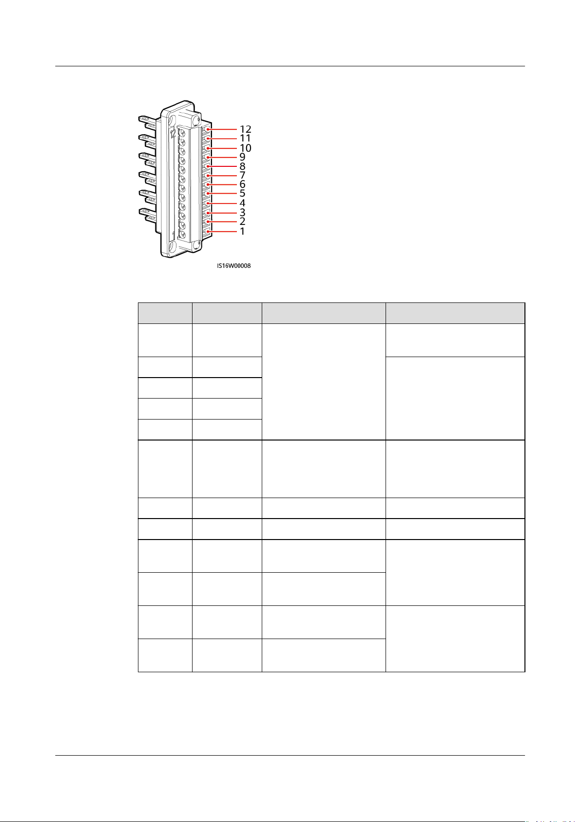
SUN2000-(12KTL-25KTL)-M5 Series
User Manual 5 Electrical Connections
Figure 5-7 Signal denitions
Table 5-3 Signal denitions
Pin Denition Function Description
1 GND Ripple control GND port for the DIN1 to
DIN5 signals
2 DIN1 Dry contact for grid
scheduling
3 DIN2
4 DIN3
5 DIN4
6 DIN5 Rapid shutdown signal+ For the rapid shutdown DI
signal or connecting to the
signal cable of an NS
protective device
7 GND GND -
8 - - -
9 485A1 RS485A1 dierential
signal+
For inverter cascading or
connecting to the RS485
signal port of a
10 485B1 RS485B1 dierential
SmartLogger
signal–
11 485A2 RS485A2 dierential
signal+
Connecting to the RS485
signal port of a power
meter
12 485B2 RS485B2 dierential
signal–
Issue 03 (2023-02-15) Copyright © Huawei Digital Power Technologies Co., Ltd. 42
Page 49
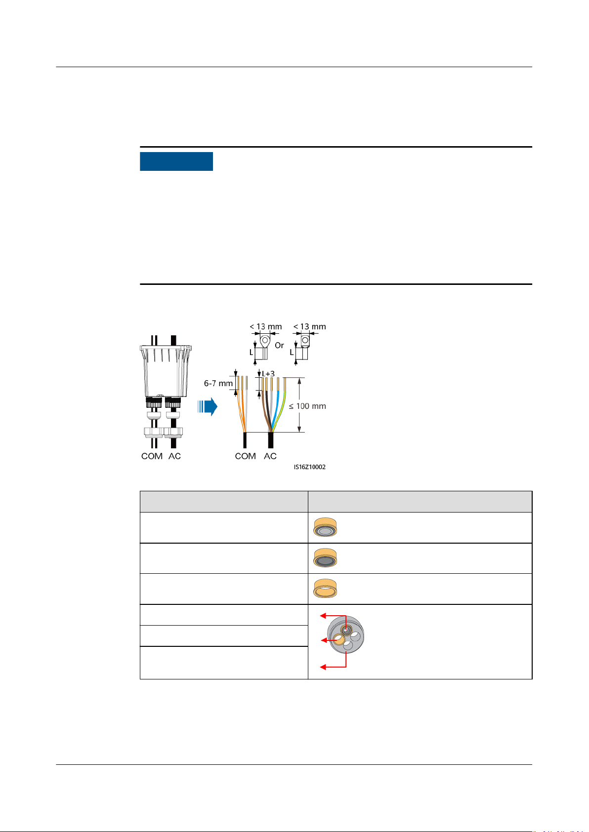
NO TICE
SUN2000-(12KTL-25KTL)-M5 Series
User Manual 5 Electrical Connections
Procedure
Step 1 Route the cables through the junction box and prepare cable terminals.
● Before routing cables, check that the sealing strips of the connection box are
intact. Otherwise, the airtightness and waterproof performance of the device
may be
● The cable stripping length must meet the requirements. Otherwise, the
airtightness and waterproof performance of the device may be aected.
● The OT terminal size must match the cross-sectional area of the AC output
power cable and M5 screw
Figure 5-8 Routing cables
aected.
specications.
Inner Diameter Rubber Plug
15 mm
22 mm
26 mm
6 mm
8.6 mm
11 mm
Step 2 Install AC output power cables and signal cables. (The following uses the RS485
signal cables as an example. For details about other signal cables, see the signal
denitions of communications ports.)
Issue 03 (2023-02-15) Copyright © Huawei Digital Power Technologies Co., Ltd. 43
Page 50
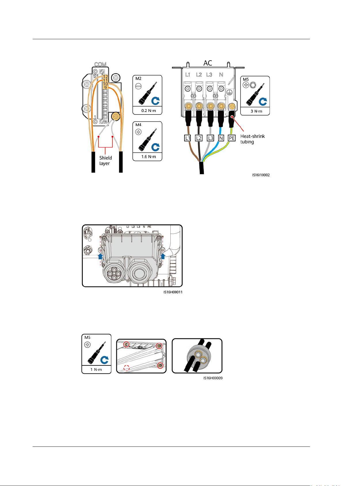
SUN2000-(12KTL-25KTL)-M5 Series
User Manual 5 Electrical Connections
Figure 5-9 Installing AC output power cables and signal cables
Step 3 Align the pin holes at both ends of the junction box with the positioning pins on
the inverter enclosure to ensure that the screw holes on the junction box are
aligned.
Figure 5-10 Aligning positioning pins
Step 4 Install the junction box, seal the unused cable holes in the rubber plugs with
waterproof plugs, and tighten the locking caps.
Figure 5-11 Installing a junction box
----End
Issue 03 (2023-02-15) Copyright © Huawei Digital Power Technologies Co., Ltd. 44
Page 51
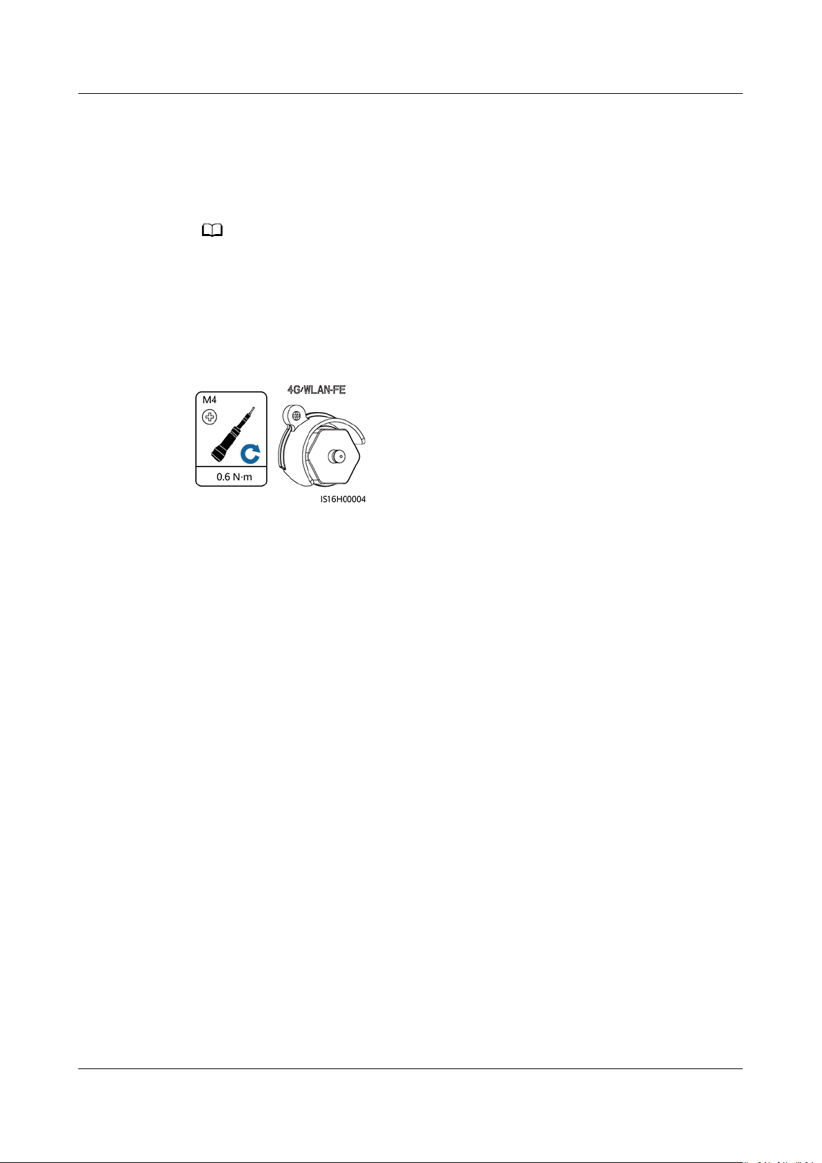
NO TE
SUN2000-(12KTL-25KTL)-M5 Series
User Manual 5 Electrical Connections
5.6 (Optional) Installing the Smart Dongle and Antitheft Components
If the Smart Dongle is used, you need to install anti-theft components after installing the
Smart Dongle.
Step 1 Install the Smart Dongle. For details, see the
Step 2 Install the anti-theft components.
Figure 5-12 Installing the Smart Dongle anti-theft components
----End
Smart Dongle Quick Guide
.
Issue 03 (2023-02-15) Copyright © Huawei Digital Power Technologies Co., Ltd. 45
Page 52
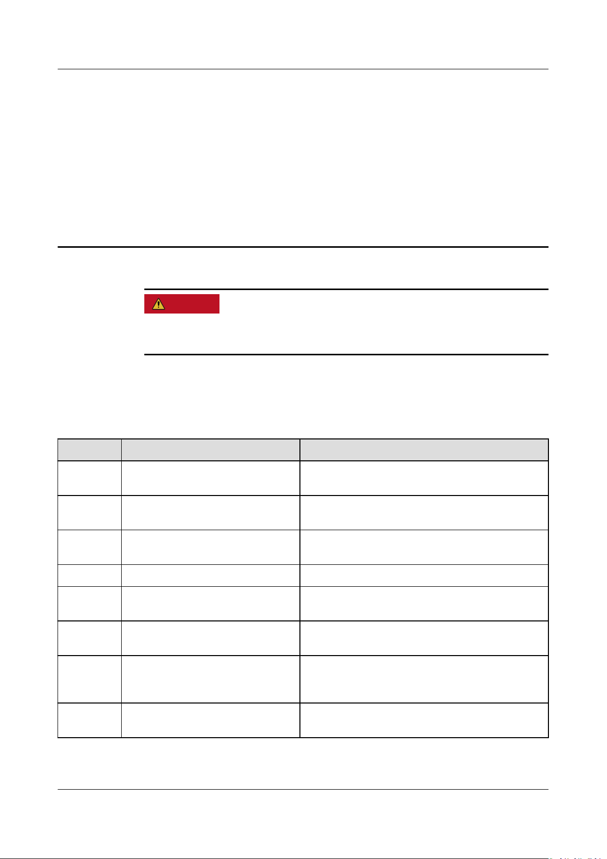
D ANGER
SUN2000-(12KTL-25KTL)-M5 Series
User Manual 6 Commissioning
6 Commissioning
● Wear insulated gloves and use insulated tools to prevent electric shocks or
short circuits.
6.1 Check Before Power-On
Table 6-1 Installation checklist
No.
1 SUN2000 installation The SUN2000 is installed correctly, securely, and
2 Smart Dongle The Smart Dongle is installed correctly and
3 Cable layout Cables are routed properly as required by the
4 Cable tie Cable ties are secured evenly and no burr exists.
5 Grounding The ground cable is connected correctly,
6 Turn o the switches The DC SWITCH and all the switches connected
7 Cable connections The AC output power cable, DC input power
Check Item Acceptance Criteria
reliably.
securely.
customer.
securely, and reliably.
to the SUN2000 are set to OFF.
cable, and signal cable are connected correctly,
securely, and reliably.
8 Unused terminals and ports Unused terminals and ports are locked by
watertight caps.
Issue 03 (2023-02-15) Copyright © Huawei Digital Power Technologies Co., Ltd. 46
Page 53
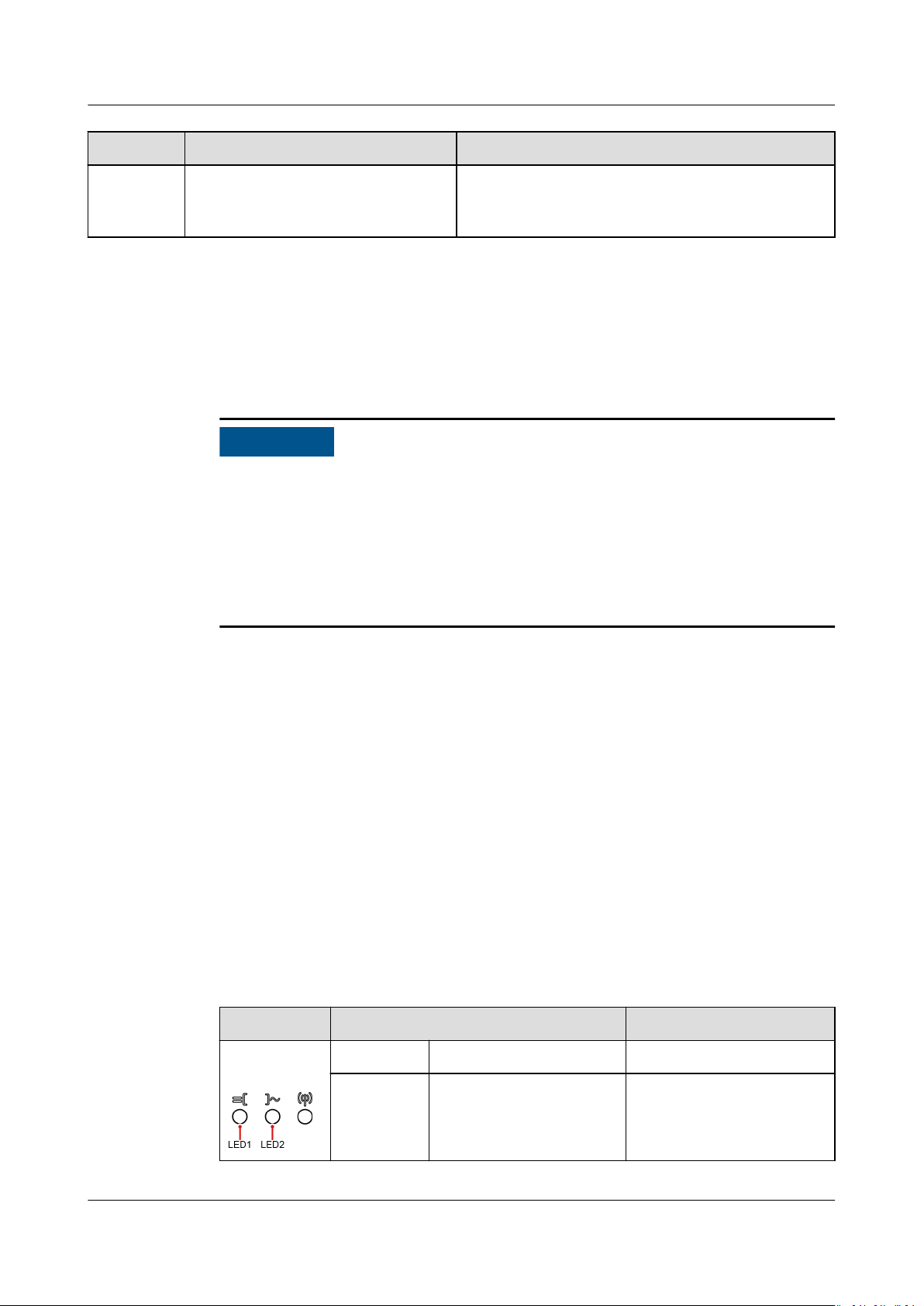
NO TICE
SUN2000-(12KTL-25KTL)-M5 Series
User Manual 6 Commissioning
No. Check Item Acceptance Criteria
9 Installation environment The installation space is proper, and the
installation environment is clean and tidy,
without foreign matter.
6.2 Powering On the System
Precautions
● Before the equipment is put into operation for the rst time, ensure that the
parameters are set correctly by professional personnel. Incorrect parameter
settings may result in noncompliance with local grid connection requirements
aect the normal operations of the equipment.
and
Procedure
Step 1 At the AC switch between the inverter and the power grid, use a multimeter to
Step 2 Turn on the AC switch between the inverter and the power grid.
Step 3 Turn on the DC switch (if any) between the PV strings and the inverter.
Step 4 (Optional) Remove the locking screw next to the DC SWITCH on the inverter.
Step 5 Set the DC SWITCH to ON.
Step 6 Observe the LED indicators to check the status of the inverter.
● If the DC power supply is connected but the AC power supply is disconnected,
the inverter will report a Grid Failure alarm. The inverter can start properly
only after the power grid recovers.
measure the grid voltage and ensure that the voltage is within the allowed
operating voltage range of the inverter. If the voltage is not in the allowed range,
check the circuits.
Table 6-2 Indicator description
Category
Running
indication
Issue 03 (2023-02-15) Copyright © Huawei Digital Power Technologies Co., Ltd. 47
Status Description
LED1 LED2 -
Steady
green
Steady green The inverter is operating
in grid-tied mode.
Page 54
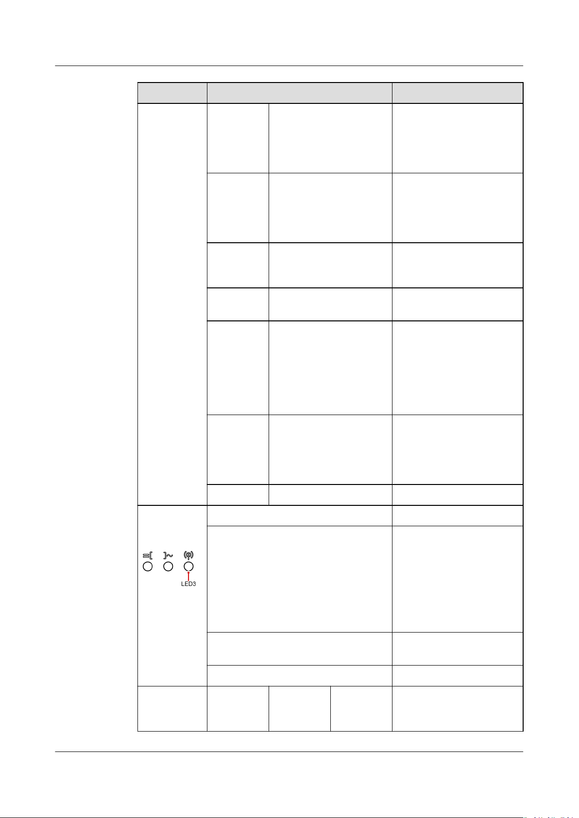
SUN2000-(12KTL-25KTL)-M5 Series
User Manual 6 Commissioning
Category Status Description
Blinking
green
O The DC is on and the AC
is o.
slowly (on
for 1s and
o for 1s)
Blinking
green
slowly (on
for 1s and
Blinking green slowly
(on for 1s and o for
1s)
Both the DC and AC are
on, but the inverter is yet
to connect to the power
grid.
o for 1s)
O Blinking green slowly
(on for 1s and o for
The DC is o and the AC
is on.
1s)
O O Both the DC and AC are
o.
Blinking
red fast
(on for
0.2s and
o for
0.2s)
- DC environment alarm
For example, the input
voltage of the PV string is
high, the PV string is
reversely connected, or
the insulation resistance
is low.
Communica
tion
indication
Device
replacement
indicator
- Blinking red fast (on for
0.2s and o for 0.2s)
AC environment alarm
For example, grid
undervoltage/overvoltage
or grid overfrequency/
underfrequency occurred.
Steady red Steady red Faulty
LED3 -
Blinking green fast (on for 0.2s and
o for 0.2s)
Communication is in
progress. (When a mobile
phone is connected to
the inverter, the indicator
blinks green slowly,
indicating that the phone
is connected to the
inverter.)
Blinking green slowly (on for 1s and
Mobile phone access
o for 1s)
O No communication
LED1 LED2 LED3 –
Issue 03 (2023-02-15) Copyright © Huawei Digital Power Technologies Co., Ltd. 48
Page 55
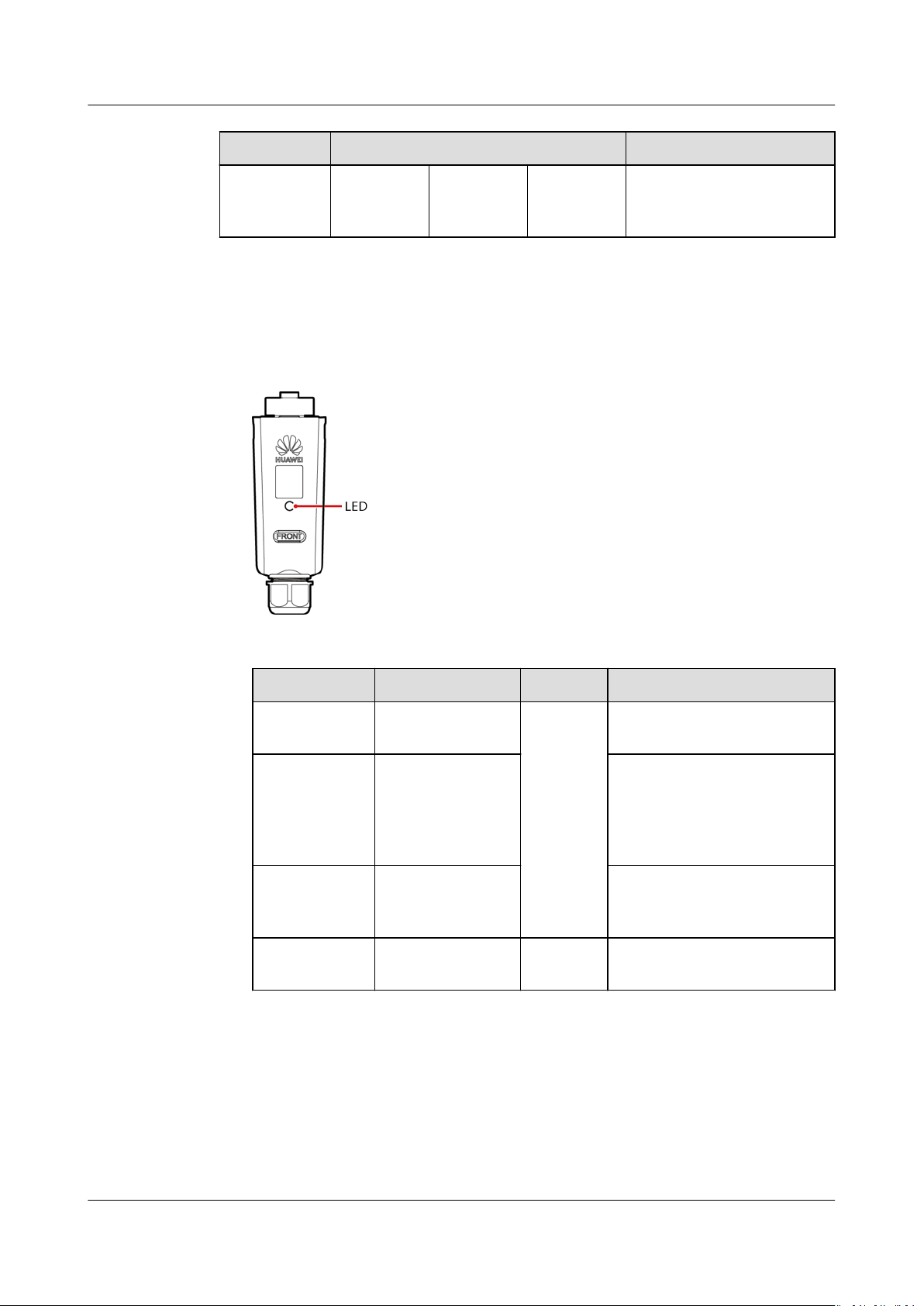
SUN2000-(12KTL-25KTL)-M5 Series
User Manual 6 Commissioning
Category Status Description
Steady red Steady red Steady red The inverter hardware is
faulty. The inverter needs
to be replaced.
Step 7 (Optional) Observe the Smart Dongle LED indicator to check the status of the
Smart Dongle.
● WLAN-FE Smart Dongle
Figure 6-1 WLAN-FE Smart Dongle
Table 6-3 Indicator description
LED Indicator
Status Remarks Description
- O Normal The Smart Dongle is not
secured or not powered on.
Yellow
(blinking
Steady on The Smart Dongle is
secured and powered on.
green and red
simultaneousl
y)
Red Blinking fast (on
for 0.2s and o
for 0.2s)
The parameters for
connecting to the router are
to be set.
Red Steady on AbnormalThe Smart Dongle is faulty
and needs to be replaced.
Issue 03 (2023-02-15) Copyright © Huawei Digital Power Technologies Co., Ltd. 49
Page 56
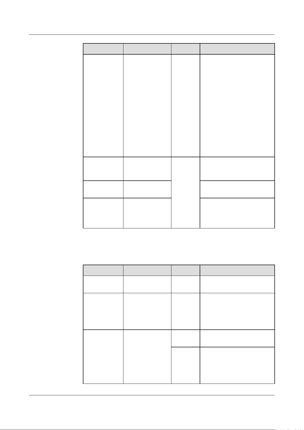
SUN2000-(12KTL-25KTL)-M5 Series
User Manual 6 Commissioning
LED Indicator Status Remarks Description
Blinking red
and green
alternately
Blinking slowly
(on for 1s and
o for 1s)
AbnormalNo communication with the
inverter:
– Remove and then insert
the Smart Dongle.
– Check whether the
inverter matches the
Smart Dongle.
– Connect the Smart
Dongle to another
inverter.
Check whether the
Smart Dongle is faulty or
the USB port of the
inverter is faulty.
Green Blinking slowly
Normal Connecting to the router
(on for 0.5s and
o for 0.5s)
Green Steady on The management system is
successfully connected.
Green Blinking fast (on
for 0.2s and o
for 0.2s)
The inverter is
communicating with the
management system
through the Smart Dongle.
● 4G Smart Dongle
Table 6-4 Indicator description
LED Indicator
Status Remarks Description
- O Normal The Smart Dongle is not
secured or not powered on.
Yellow
(blinking
Steady on Normal The Smart Dongle is
secured and powered on.
green and red
simultaneousl
y)
Green The blinking
interval is 2s.
Normal Dialing (lasts for less than 1
minute)
The indicator is
on for 0.1s and
o for 1.9s.
AbnormalIf the duration is longer
than 1 minute, the 4G
parameter settings are
incorrect. Re-congure the
parameters.
Issue 03 (2023-02-15) Copyright © Huawei Digital Power Technologies Co., Ltd. 50
Page 57
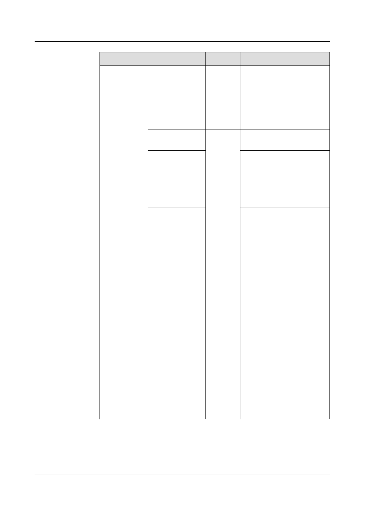
SUN2000-(12KTL-25KTL)-M5 Series
User Manual 6 Commissioning
LED Indicator Status Remarks Description
Blinking slowly
(on for 1s and
Normal The dialup is successful
(lasts for less than 30s).
o for 1s)
AbnormalIf the duration is longer
than 30s, the management
system parameters are
incorrectly set. Re-congure
the parameters.
Steady on Normal The management system is
successfully connected.
Blinking fast (on
for 0.2s and o
for 0.2s)
The inverter is
communicating with the
management system
through the Smart Dongle.
Red Steady on AbnormalThe Smart Dongle is faulty
and needs to be replaced.
Blinking fast (on
for 0.2s and o
for 0.2s)
The Smart Dongle has no
SIM card or the SIM card is
in poor contact. Check
whether the SIM card has
been installed or is in good
contact. If not, install a SIM
card or remove and reinsert the SIM card.
Blinking slowly
(on for 1s and
o for 1s)
The Smart Dongle fails to
be connected to a
management system
because the SIM card has
poor or no reception, or has
run out of mobile data. If
the Smart Dongle is reliably
connected, check the SIM
card connectivity through
the app. If you have poor or
no reception, contact the
carrier. Check whether the
tari and mobile data plan
of the SIM card are
adequate. If not, ensure
sucient balance in the
SIM card or purchase a data
package.
Issue 03 (2023-02-15) Copyright © Huawei Digital Power Technologies Co., Ltd. 51
Page 58
SUN2000-(12KTL-25KTL)-M5 Series
User Manual 6 Commissioning
LED Indicator Status Remarks Description
Blinking red
and green
alternately
----End
Blinking slowly
(on for 1s and
o for 1s)
No communication with the
inverter:
– Remove and then insert
the Smart Dongle.
– Check whether the
inverter matches the
Smart Dongle.
– Connect the Smart
Dongle to another
inverter.
Check whether the
Smart Dongle is faulty or
the USB port of the
inverter is faulty.
Issue 03 (2023-02-15) Copyright © Huawei Digital Power Technologies Co., Ltd. 52
Page 59
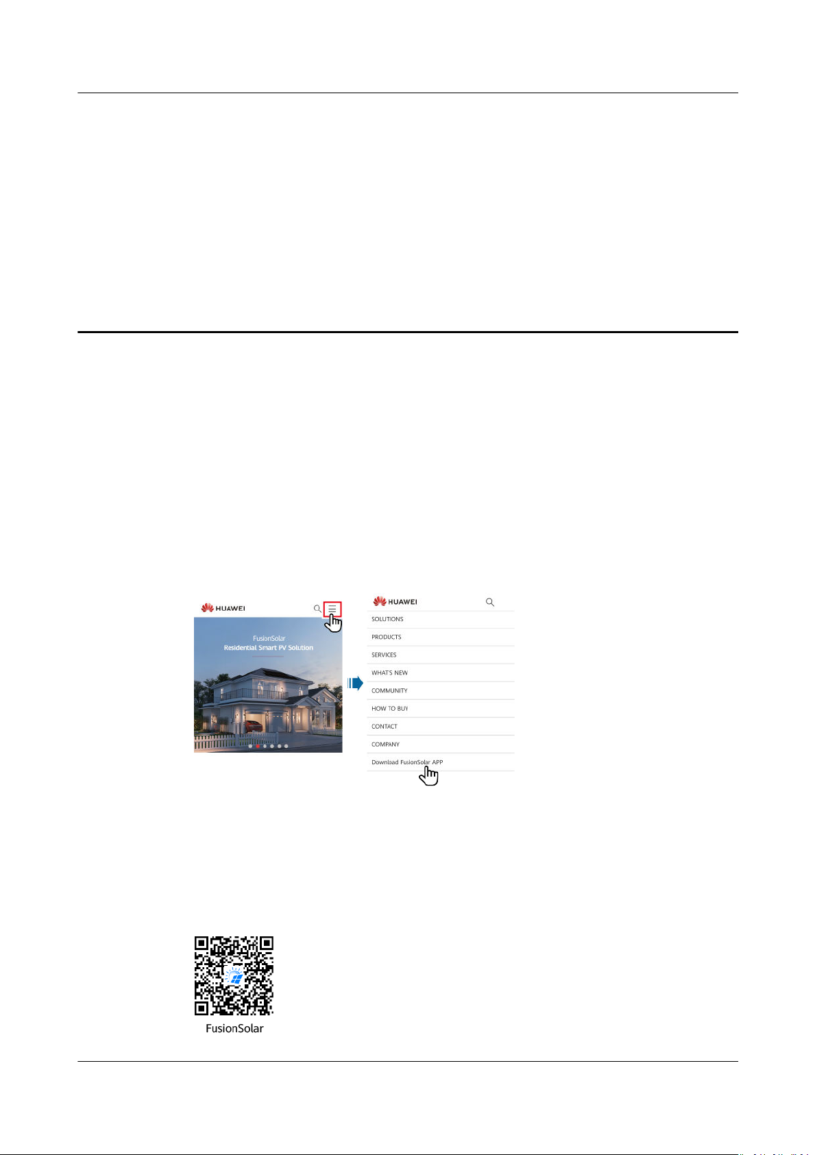
SUN2000-(12KTL-25KTL)-M5 Series
User Manual 7 Man-Machine Interactions
7 Man-Machine Interactions
7.1 App Commissioning
7.1.1 Downloading the FusionSolar App
● Method 1: Access https://solar.huawei.com using the mobile phone browser
and download the latest installation package.
Figure 7-1 Download Mode
● Method 2: Search for FusionSolar on Huawei AppGallery and download the
latest installation package.
● Method 3: Scan the following QR code and download the latest installation
package.
Figure 7-2 QR code
Issue 03 (2023-02-15) Copyright © Huawei Digital Power Technologies Co., Ltd. 53
Page 60
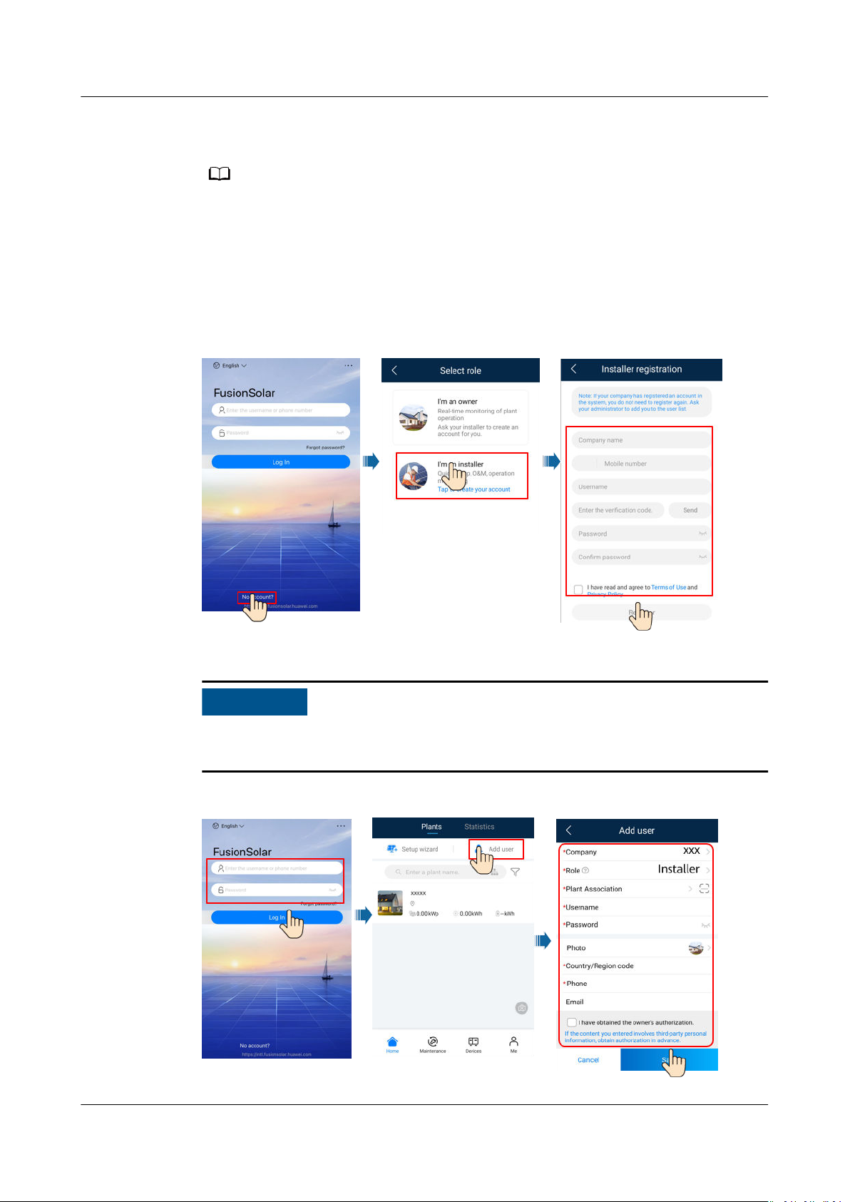
NO TE
NO TICE
SUN2000-(12KTL-25KTL)-M5 Series
User Manual 7 Man-Machine Interactions
7.1.2 (Optional) Registering an Installer Account
● If you have an installer account, skip this step.
● You can register an account only using a mobile phone only in China.
● The mobile number or email address used for registration is the user name for logging
in to the FusionSolar App.
Create the
rst installer account and create a domain named after the company
name.
Figure 7-3 Creating the rst installer account
To create multiple installer accounts for a company, log in to the FusionSolar App
and tap Add User to create an installer account.
Figure 7-4 Creating multiple installer accounts for the same company
Issue 03 (2023-02-15) Copyright © Huawei Digital Power Technologies Co., Ltd. 54
Page 61
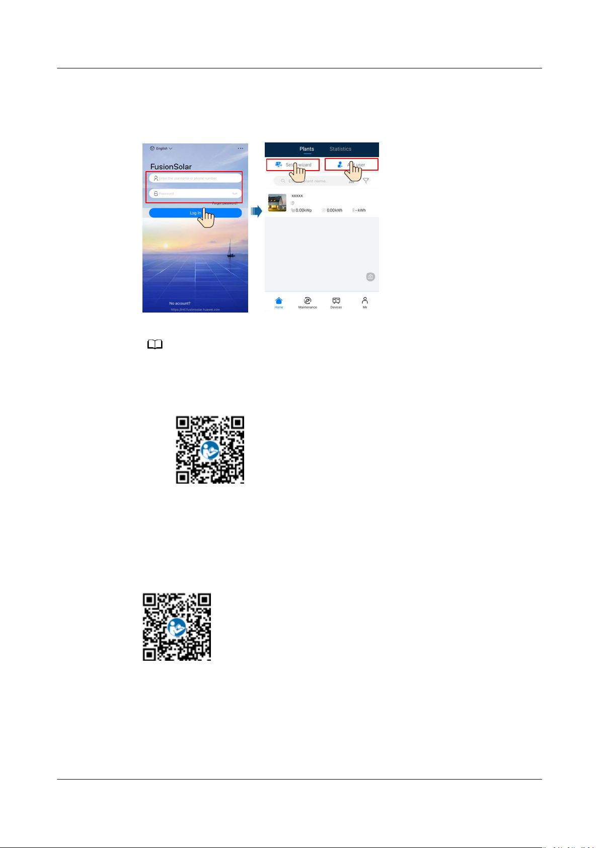
NO TE
SUN2000-(12KTL-25KTL)-M5 Series
User Manual 7 Man-Machine Interactions
7.1.3 Creating a PV Plant and a User
Figure 7-5 Creating a PV plant and a user
● In the quick settings, the grid code is set to N/A by default (automatic startup is not
supported). Set the grid code based on the area where the PV plant is located.
● For details about how to use the site deployment wizard, see
Guide
. You can scan the QR code to download the quick guide.
FusionSolar App Quick
7.1.4 (Optional) Setting the Physical Layout of the Smart PV Optimizers
For details about the optimizer physical layout, see
or online help of the management system.
FusionSolar App Quick Guide
7.1.5 Detecting Optimizer Disconnection
Log in to the FusionSolar app, choose Device Commissioning > Maintenance >
Optimizer disconnection detection, tap the detection button to detect the
optimizer disconnection, and rectify the fault based on the detection result.
Issue 03 (2023-02-15) Copyright © Huawei Digital Power Technologies Co., Ltd. 55
Page 62
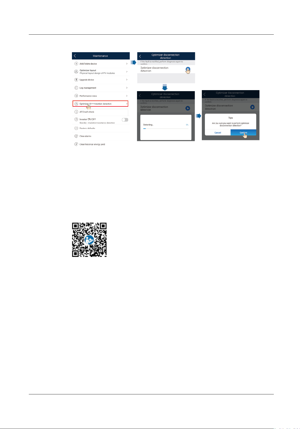
SUN2000-(12KTL-25KTL)-M5 Series
User Manual 7 Man-Machine Interactions
Figure 7-6 Detect optimizer disconnection
7.2 Parameters Settings
Go to the Device Commissioning screen and set SUN2000 parameters. For details
about entering the Device Commissioning screen, see B Device Commissioning.
To set more parameters, tap Settings. For details about the parameters, see the
FusionSolar App and SUN2000 App User Manual
code to obtain the document.
7.2.1 Energy Control
7.2.1.1 Grid-tied Point Control
Function
Limits or reduces the output power of the PV power system to ensure that the
output power is within the power deviation limit.
. You can also scan the QR
Procedure
Step 1 On the home screen, choose Power adjustment > Grid-tied point control.
Issue 03 (2023-02-15) Copyright © Huawei Digital Power Technologies Co., Ltd. 56
Page 63
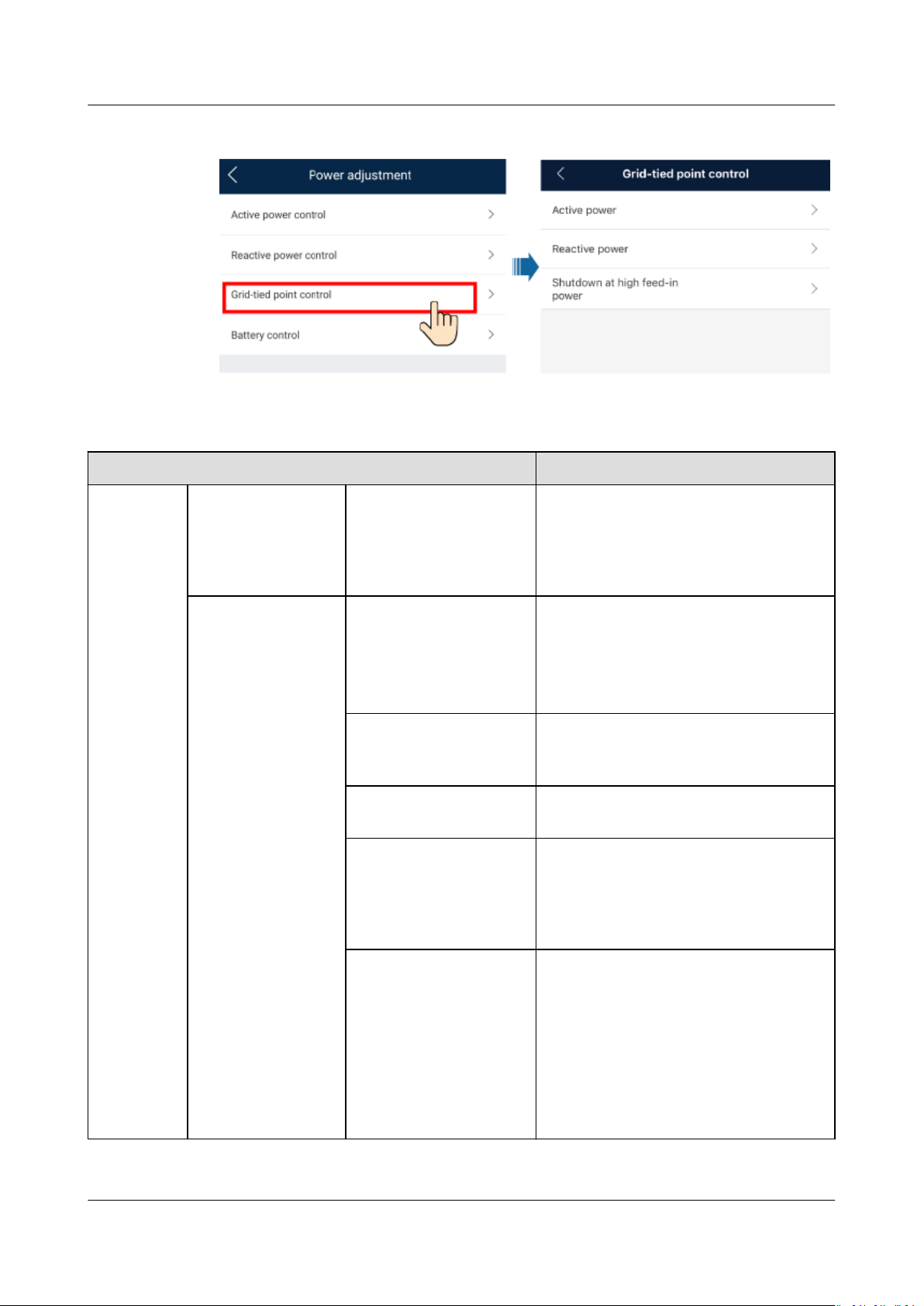
SUN2000-(12KTL-25KTL)-M5 Series
User Manual 7 Man-Machine Interactions
Figure 7-7 Grid-tied point control
Table 7-1 Grid-tied point control
Parameter Name Description
Active
power
Unlimited - If this parameter is set to Unlimited,
the output power of the SUN2000 is
not limited and the SUN2000 can
connect to the power grid at the
rated power.
Grid connection
with zero power
Closed-loop controller ● If multiple SUN2000s are
cascaded, set this parameter to
SDongle/SmartLogger.
● If there is only one SUN2000, set
this parameter to Inverter.
Limitation mode Total power indicates export
limitation of the total power at the
grid-tied point.
Power adjustment
period
Power control
hysteresis
Species the shortest interval for a
single anti-backfeeding adjustment.
Species the dead zone for adjusting
the SUN2000 output power. If the
power uctuation is within the power
control hysteresis, the power is not
adjusted.
Active power output
limit for fail-safe
Species the derating value of the
SUN2000 active power by percentage.
If the Smart Dongle does not detect
any meter data or the
communication between the Smart
Dongle and the SUN2000 is
disconnected, the Smart Dongle
delivers the derating value of the
SUN2000 active power by percentage.
Issue 03 (2023-02-15) Copyright © Huawei Digital Power Technologies Co., Ltd. 57
Page 64
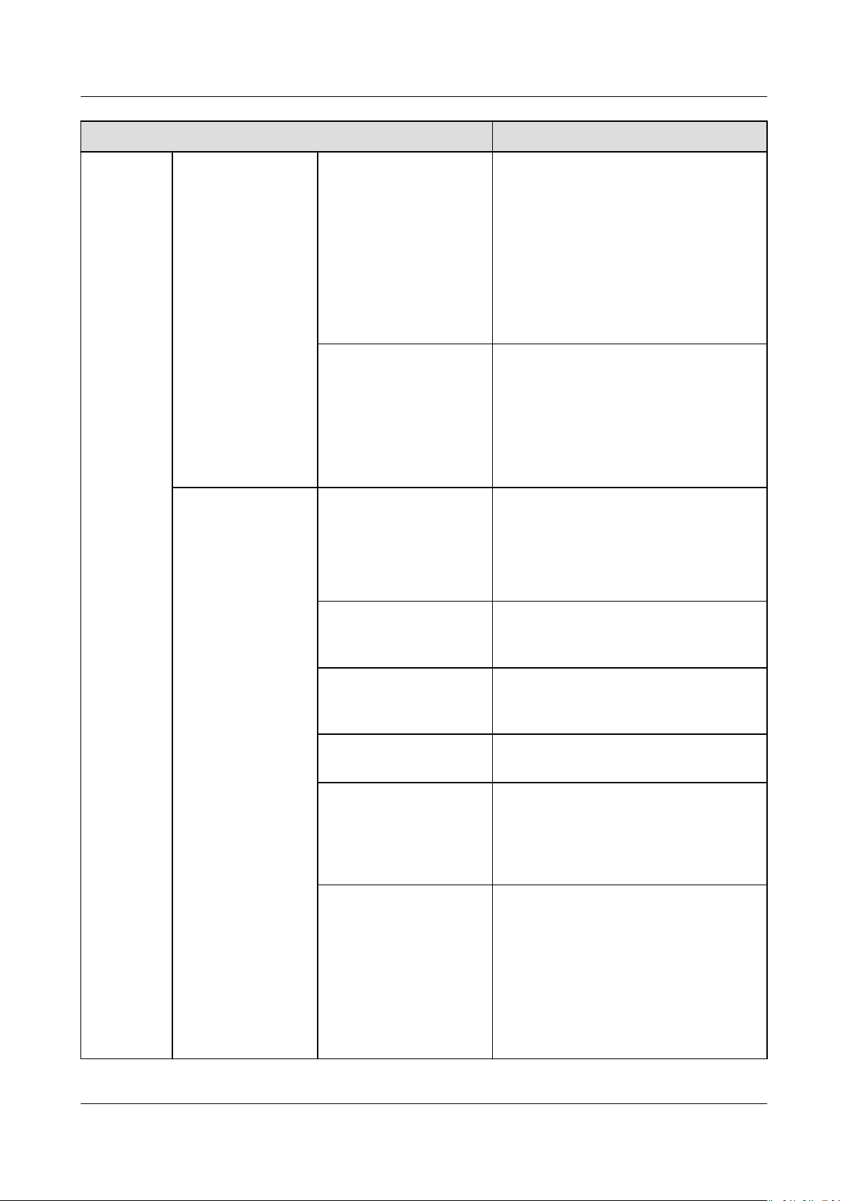
SUN2000-(12KTL-25KTL)-M5 Series
User Manual 7 Man-Machine Interactions
Parameter Name Description
Grid connection
with limited power
(kW)
Communication
disconnection fail-safe
In the SUN2000 anti-backfeeding
scenario, if this parameter is set to
Enable, the SUN2000 will derate
according to the active power
derating percentage when the
communication between the
SUN2000 and the Smart Dongle is
disconnected for a period longer than
Communication disconnection
detection time.
Communication
disconnection
detection time
Species the time for determining the
communication disconnection
between the SUN2000 and the
Dongle.
This parameter is displayed when
Communication disconnection failsafe is set to Enable.
Closed-loop controller ● If multiple SUN2000s are
cascaded, set this parameter to
SDongle/SmartLogger.
● If there is only one SUN2000, set
this parameter to Inverter.
Limitation mode Total power indicates export
limitation of the total power at the
grid-tied point.
Maximum grid feed-in
power
Species the maximum active power
transmitted from the grid-tied point
to the power grid.
Power adjustment
period
Power control
hysteresis
Species the shortest interval for a
single anti-backfeeding adjustment.
Species the dead zone for adjusting
the SUN2000 output power. If the
power uctuation is within the power
control hysteresis, the power is not
adjusted.
Active power output
limit for fail-safe
Species the derating value of the
SUN2000 active power by percentage.
If the Smart Dongle does not detect
any meter data or the
communication between the Smart
Dongle and the SUN2000 is
disconnected, the Smart Dongle
delivers the derating value of the
SUN2000 active power by percentage.
Issue 03 (2023-02-15) Copyright © Huawei Digital Power Technologies Co., Ltd. 58
Page 65
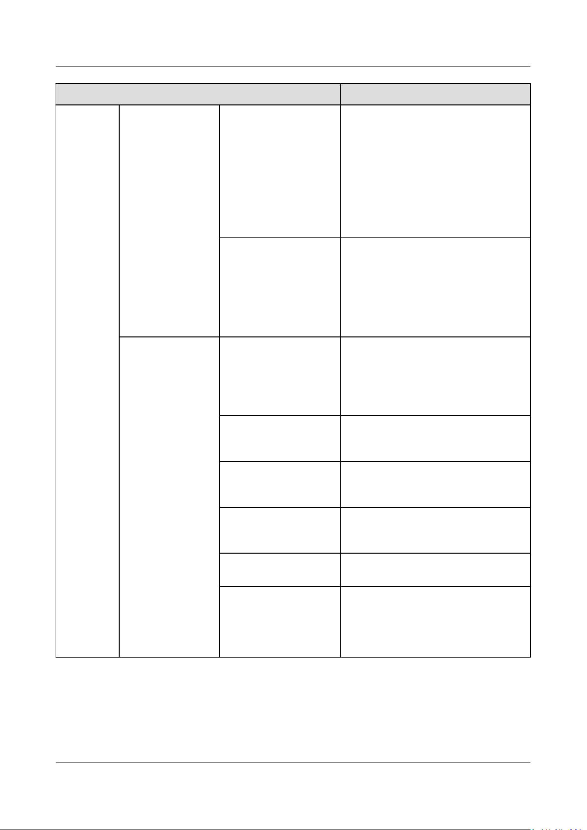
SUN2000-(12KTL-25KTL)-M5 Series
User Manual 7 Man-Machine Interactions
Parameter Name Description
Grid connection
with limited power
(%)
Communication
disconnection fail-safe
In the SUN2000 anti-backfeeding
scenario, if this parameter is set to
Enable, the SUN2000 will derate
according to the active power
derating percentage when the
communication between the
SUN2000 and the Smart Dongle is
disconnected for a period longer than
Communication disconnection
detection time.
Communication
disconnection
detection time
Species the time for determining the
communication disconnection
between the SUN2000 and the
Dongle.
This parameter is displayed when
Communication disconnection failsafe is set to Enable.
Closed-loop controller ● If multiple SUN2000s are
cascaded, set this parameter to
SDongle/SmartLogger.
● If there is only one SUN2000, set
this parameter to Inverter.
Limitation mode Total power indicates export
limitation of the total power at the
grid-tied point.
PV plant capacity Species the total maximum active
power in the SUN2000 cascading
scenario.
Maximum grid feed-in
power
Species the percentage of the
maximum active power of the gridtied point to the PV plant capacity.
Power adjustment
period
Power control
hysteresis
Species the shortest interval for a
single anti-backfeeding adjustment.
Species the dead zone for adjusting
the SUN2000 output power. If the
power uctuation is within the power
control hysteresis, the power is not
adjusted.
Issue 03 (2023-02-15) Copyright © Huawei Digital Power Technologies Co., Ltd. 59
Page 66
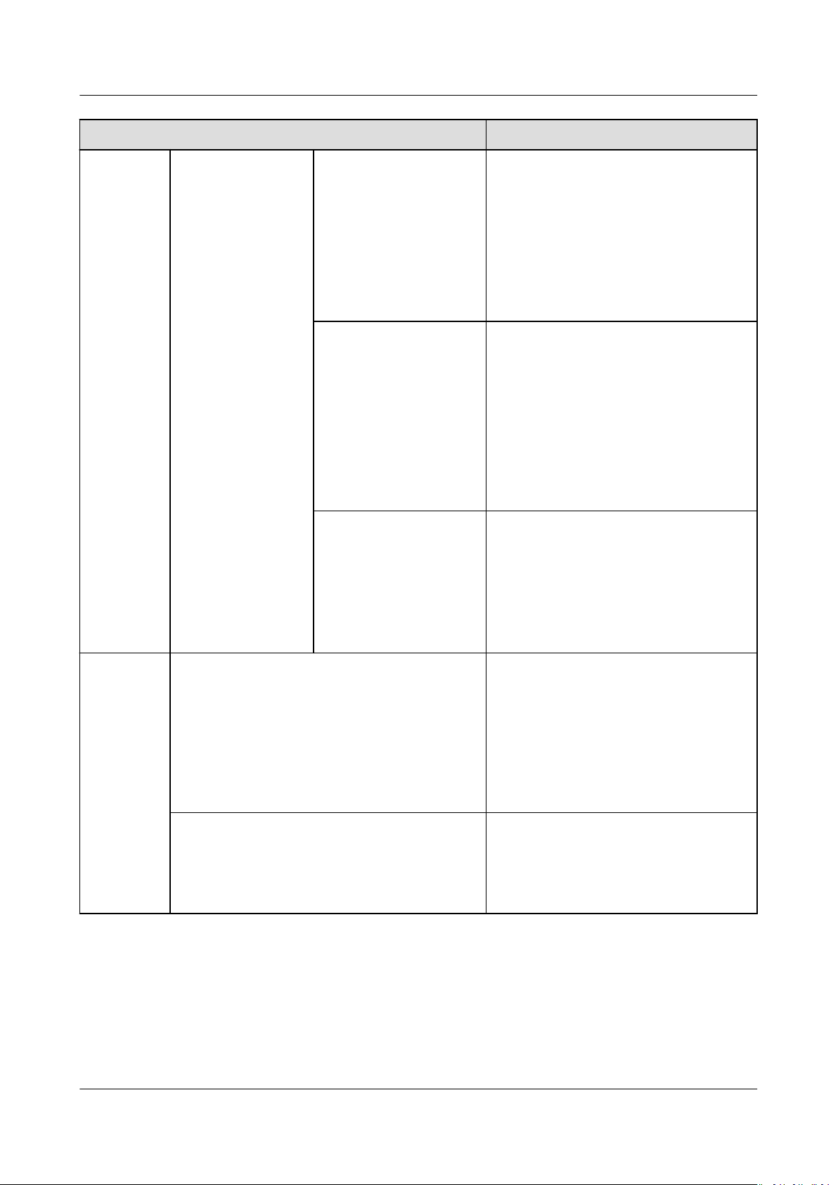
SUN2000-(12KTL-25KTL)-M5 Series
User Manual 7 Man-Machine Interactions
Parameter Name Description
Active power output
limit for fail-safe
Communication
disconnection fail-safe
Communication
disconnection
detection time
Species the derating value of the
SUN2000 active power by percentage.
If the Smart Dongle does not detect
any meter data or the
communication between the Smart
Dongle and the SUN2000 is
disconnected, the Smart Dongle
delivers the derating value of the
SUN2000 active power by percentage.
In the SUN2000 anti-backfeeding
scenario, if this parameter is set to
Enable, the SUN2000 will derate
according to the active power
derating percentage when the
communication between the
SUN2000 and the Smart Dongle is
disconnected for a period longer than
Communication disconnection
detection time.
Species the time for determining the
communication disconnection
between the SUN2000 and the
Dongle.
This parameter is displayed when
Communication disconnection failsafe is set to Enable.
Shutdown
at high
feed-in
a
power
Shutdown at high feed-in power ● The default value is Disable.
● If this parameter is set to Enable,
the inverter shuts down for
protection when the gridconnection point power exceeds
the threshold and remains in this
condition for the
specied time
threshold.
Upper feed-in power threshold for inverter
shutdown (kW)
● The default value is 0. This
parameter species the power
threshold of the grid-connection
point for triggering inverter
shutdown.
Issue 03 (2023-02-15) Copyright © Huawei Digital Power Technologies Co., Ltd. 60
Page 67
NO TE
SUN2000-(12KTL-25KTL)-M5 Series
User Manual 7 Man-Machine Interactions
Parameter Name Description
High feed-in power duration threshold for
triggering inverter shutdown (s)
The default value is 20. This
parameter species the duration
threshold of high feed-in power for
triggering inverter shutdown.
● When High feed-in power
duration threshold for triggering
inverter shutdown is set to 5,
Shutdown at high feed-in power
takes precedence.
● When High feed-in power
duration threshold for triggering
inverter shutdown is set to 20,
Grid connection with limited
power takes precedence (when
Active power control is set to
Grid connection with limited
power).
Note a: This parameter is supported only for the AS4777 grid code.
● The communication disconnection fail-safe function must be used together with grid
connection with zero power or grid connection with limited power. If grid connection
with zero power or grid connection with limited power is not set, you are advised to
disable the communication disconnection fail-safe function. Otherwise, the inverter
enters unnecessary output power protection state.
● If grid connection with zero power or grid connection with limited power is disabled, the
inverter automatically disables the communication disconnection fail-safe function. If
grid connection with zero power or grid connection with limited power is enabled again,
you need to manually enable or disable the communication disconnection fail-safe
function based on networking requirements.
----End
7.2.1.2 Apparent Power Control on the Inverter Output Side
On the home screen, tap Settings > Power adjustment to set inverter
parameters.
Issue 03 (2023-02-15) Copyright © Huawei Digital Power Technologies Co., Ltd. 61
Page 68
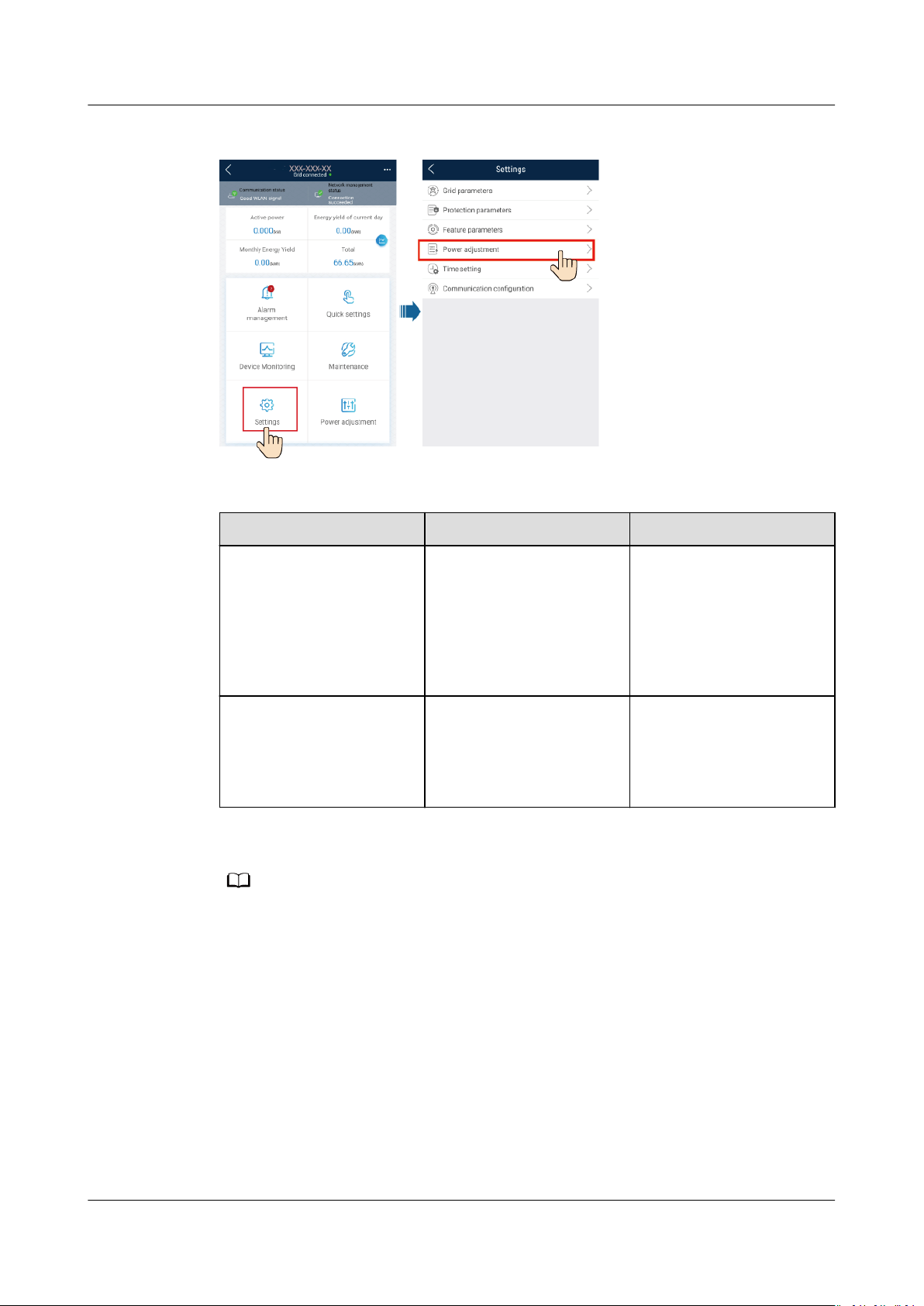
NO TE
SUN2000-(12KTL-25KTL)-M5 Series
User Manual 7 Man-Machine Interactions
Figure 7-8 Apparent power control
Table 7-2 Apparent power
7.2.2 AFCI
Parameter Description Value Range
Maximum apparent
power (kVA)
Species the output
upper threshold for the
[Maximum active power,
S
]
max
maximum apparent
power to adapt to the
capacity requirements of
standard and customized
inverters.
Maximum active power
(kW)
Species the output
upper threshold for the
[0.1, P
max
]
maximum active power
to adapt to dierent
market requirements.
The lower threshold for the maximum apparent power is the maximum active power. To
lower the maximum apparent power, lower the maximum active power rst.
Function
If PV modules or cables are not properly connected or damaged, electric arcs may
occur, which may cause re. Huawei SUN2000s provide unique arc detection in
compliance with UL 1699B-2018 to ensure the safety of users' lives and property.
This function is enabled by default. The SUN2000 automatically detects arc faults.
To disable this function, log in to the FusionSolar App, enter the Device
Commissioning screen, choose Settings > Feature parameters, and disable AFCI.
Issue 03 (2023-02-15) Copyright © Huawei Digital Power Technologies Co., Ltd. 62
Page 69
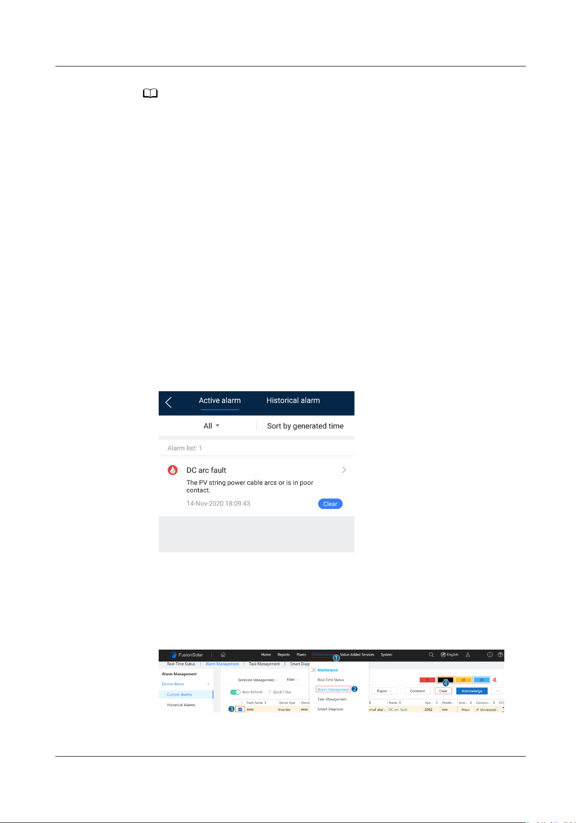
NO TE
SUN2000-(12KTL-25KTL)-M5 Series
User Manual 7 Man-Machine Interactions
The AFCI function works only with Huawei optimizers or ordinary PV modules, but does not
support third-party optimizers or intelligent PV modules.
Clearing Alarms
The AFCI function involves the DC arc fault alarm.
The SUN2000 has the AFCI alarm automatic clearance mechanism. If an alarm is
triggered for less than
clears the alarm. If the alarm is triggered for
the SUN2000 locks for protection. You need to manually clear the alarm on the
SUN2000 so that it can work properly.
You can manually clear the alarm as follows:
● Method 1: FusionSolar App
Log in to the FusionSolar App and choose Me > Device commissioning. On
the Device commissioning screen, connect and log in to the SUN2000 that
generates the AFCI alarm, tap Alarm management, and tap Clear on the
right of the DC arc fault alarm to clear the alarm.
ve times within 24 hours, the SUN2000 automatically
ve times or more within 24 hours,
Figure 7-9 Alarm management
● Method 2: FusionSolar Smart PV Management System
Log in to the FusionSolar Smart PV Management System using a non-owner
account, choose Maintenance > Alarm Management, select the DC arc fault
alarm, and click Clear to clear the alarm.
Figure 7-10 Clearing alarms
Issue 03 (2023-02-15) Copyright © Huawei Digital Power Technologies Co., Ltd. 63
Page 70

SUN2000-(12KTL-25KTL)-M5 Series
User Manual 7 Man-Machine Interactions
Switch to the owner account with PV plant management rights. On the home
page, click the PV plant name to go to the PV plant page, and click OK as
prompted to clear the alarm.
Issue 03 (2023-02-15) Copyright © Huawei Digital Power Technologies Co., Ltd. 64
Page 71
D ANGER
WARNING
WARNING
SUN2000-(12KTL-25KTL)-M5 Series
User Manual 8 Maintenance
8 Maintenance
● Wear insulated gloves and use insulated tools to prevent electric shocks or
short circuits.
● Before performing maintenance, power o the equipment, follow the
instructions on the delayed discharge label, and wait for a period of time as
specied to ensure that the equipment is not energized.
8.1 Powering O the System
Precautions
● After the system is powered o, the inverter is still energized and hot, which
may cause electric shocks or burns. Therefore, wait for 5 minutes after power-
and then put on insulated gloves to operate the inverter.
o
● Power o the system before maintaining optimizers and PV strings. Otherwise,
electric shocks may occur when the PV strings are energized.
Procedure
Issue 03 (2023-02-15) Copyright © Huawei Digital Power Technologies Co., Ltd. 65
Step 1 Send a shutdown command on the app.
Step 2 Turn o the AC switch between the inverter and the power grid.
Step 3 Set DC SWITCH to OFF.
Page 72
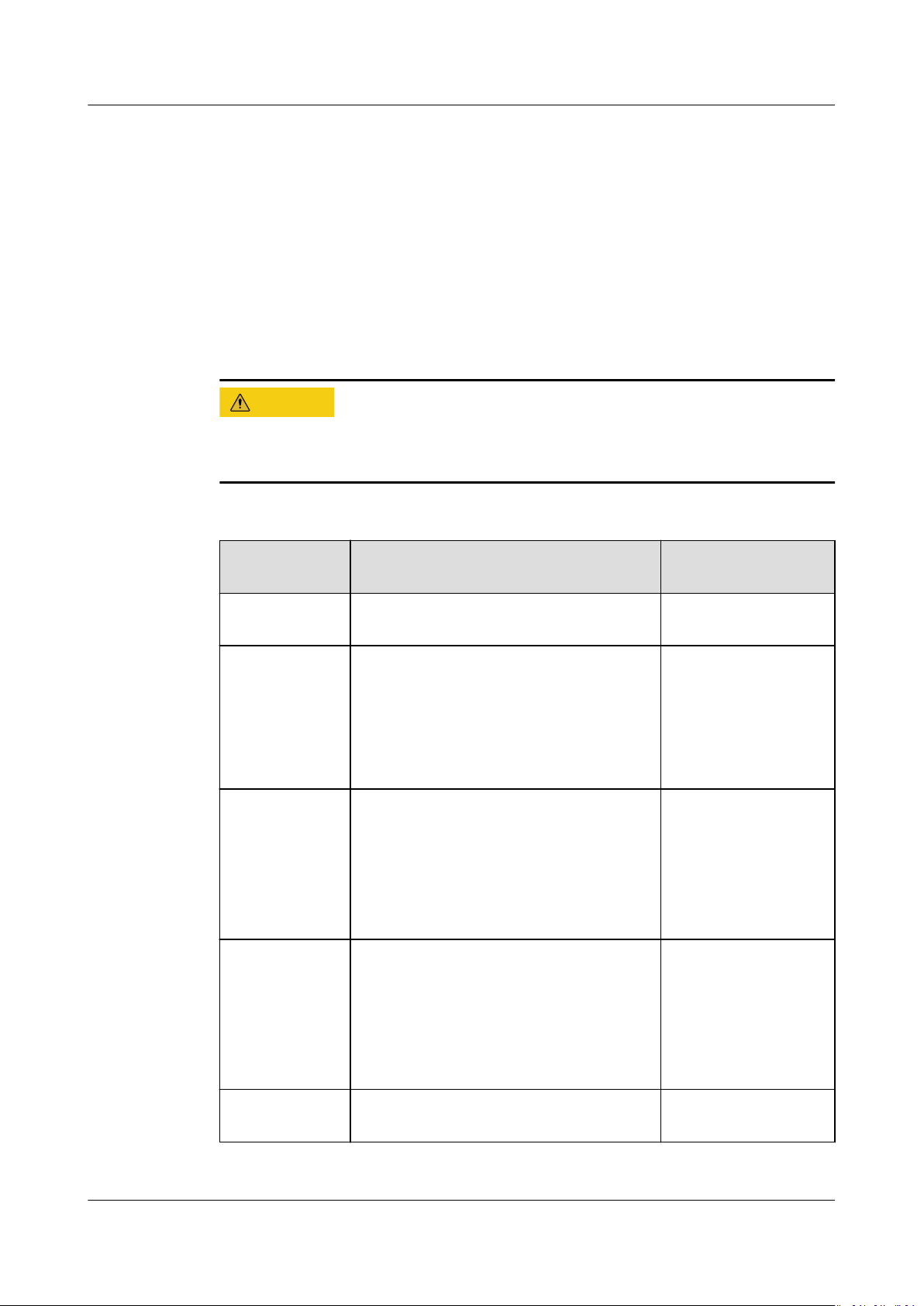
CA UTION
SUN2000-(12KTL-25KTL)-M5 Series
User Manual 8 Maintenance
Step 4 (Optional) Install the locking screw next to DC SWITCH.
Step 5 Turn o the DC switch between the inverter and PV strings.
----End
8.2 Routine Maintenance
To ensure that the SUN2000 can operate properly for a long term, you are advised
to perform routine maintenance on it as described in this chapter.
Before cleaning the system, connecting cables, and ensuring the grounding
reliability, power o the system.
Table 8-1 Maintenance checklist
Check Item Check Method Maintenance
Interval
System
cleanliness
System
operating
status
Electrical
connection
Grounding
reliability
Check periodically that the heat sinks
are free from obstacles and dust.
● Check that the SUN2000 is not
damaged or deformed.
● Check that the SUN2000 operates
with no abnormal sound.
● Check that all SUN2000 parameters
are correctly set during operation.
● Check that cables are secured.
● Check that cables are intact, and
that in particular, the parts touching
the metallic surface are not
scratched.
Check that ground cables are securely
connected.
Once every 6 to 12
months
Once every 6
months
The rst inspection is
6 months after the
initial
commissioning.
From then on, the
interval can be 6 to
12 months.
The rst inspection is
6 months after the
initial
commissioning.
From then on, the
interval can be 6 to
12 months.
Issue 03 (2023-02-15) Copyright © Huawei Digital Power Technologies Co., Ltd. 66
Air tightness Check that all terminals and ports are
properly sealed.
Once a year
Page 73
NO TE
SUN2000-(12KTL-25KTL)-M5 Series
User Manual 8 Maintenance
8.3 Troubleshooting
Contact your dealer if all failure analysis procedures listed above are completed and the
fault still exists.
Alarm severities are dened as follows:
● Major: The inverter is faulty. As a result, the output power decreases or the
grid-tied power generation is stopped.
● Minor: Some components are faulty without aecting the grid-tied power
generation.
● Warning: The inverter works properly. The output power decreases or some
authorization functions fail due to external factors.
Table 8-2 Common alarms and troubleshooting measures
AlarmIDAlarm
Name
2001 High
string
input
voltage
2003 DC arc
fault
Alarm
Severity
Major The PV array is not
Major The PV string
Possible Causes Troubleshooting
properly
congured.
Excessive PV
modules are
connected in series
to the PV string,
and therefore the
PV string opencircuit voltage
exceeds the
maximum inverter
operating voltage.
● Cause ID 1: PV
strings 1 and 2
● Cause ID 2: PV
strings 3 and 4
power cables arc or
are in poor contact.
Cause ID 1–4: PV
strings 1–4
Reduce the number of PV modules
connected in series to the PV string until
the PV string open-circuit voltage is less
than or equal to the maximum inverter
operating voltage. After the PV string
conguration is corrected, the alarm
disappears.
Check whether the PV string cables arc
or are in poor contact.
Issue 03 (2023-02-15) Copyright © Huawei Digital Power Technologies Co., Ltd. 67
Page 74
SUN2000-(12KTL-25KTL)-M5 Series
User Manual 8 Maintenance
AlarmIDAlarm
Name
2011 String
reverse
connectio
n
2012 String
current
backfeed
2021 AFCI self-
check
failure
Alarm
Possible Causes Troubleshooting
Severity
Major The PV string
polarity is reversed.
Cause ID 1–4: PV
strings 1–4
Warning The number of PV
modules connected
in series to the PV
string is
insucient. As a
result, the terminal
voltage is lower
than that of other
strings.
Cause ID 1–4: PV
strings 1–4
Major Cause ID = 1
The AFCI self-check
fails.
Check whether the PV string is reversely
connected to the inverter. If yes, wait
until the solar irradiance declines at
night and the PV string current drops to
below 0.5 A. Then, turn o the DC
switch and correct the PV string
connection.
1. Check whether the number of PV
modules connected in series to the
PV string is less than that of other PV
strings. If yes, wait until the PV string
current drops below 0.5 A, turn o all
DC switches, and adjust the number
of PV modules in the PV string.
2. Check whether the open-circuit
voltage of the PV string is abnormal.
3. Check whether the PV string is
shaded.
Turn o the AC output switch and DC
input switch, and then turn them on
after 5 minutes. If the alarm persists,
contact Huawei technical support.
2031 Phase
wire
shortcircuited
to PE
Major Cause ID = 1
The impedance of
the output phase
wire to PE is low or
the output phase
wire is shortcircuited to PE.
2032 Grid loss Major Cause ID = 1
● Power grid
outage occurs.
● The AC circuit is
disconnected or
the AC switch is
o.
Check the impedance of the output
phase wire to PE, locate the position
with low impedance, and rectify the
fault.
1. The alarm is cleared automatically
after the power grid recovers.
2. Check whether the AC circuit is
disconnected or the AC switch is o.
Issue 03 (2023-02-15) Copyright © Huawei Digital Power Technologies Co., Ltd. 68
Page 75
SUN2000-(12KTL-25KTL)-M5 Series
User Manual 8 Maintenance
AlarmIDAlarm
Name
2033 Grid
undervolt
age
2034 Grid
overvolta
ge
Alarm
Possible Causes Troubleshooting
Severity
Major Cause ID = 1
The power grid
voltage is below
the lower threshold
or the low-voltage
duration has lasted
for more than the
specied by
value
LVRT.
Major Cause ID = 1
The power grid
voltage exceeds the
upper threshold or
the high voltage
duration has lasted
for more than the
specied by
value
HVRT.
1. If the alarm occurs occasionally, the
power grid may be abnormal
temporarily. The inverter
automatically recovers after detecting
that the power grid becomes normal.
2. If the alarm persists, check whether
the power grid voltage is within the
acceptable range. If not, contact the
local power operator. If yes, modify
the grid undervoltage protection
threshold through the app,
SmartLogger, or NMS with the
consent of the local power operator.
3. If the alarm persists for a long time,
check the AC circuit breaker and AC
output power cable.
1. If the alarm occurs occasionally, the
power grid may be abnormal
temporarily. The inverter
automatically recovers after detecting
that the power grid becomes normal.
2. If the alarm persists, check whether
the power grid frequency is within
the acceptable range. If not, contact
the local power operator. If yes,
modify the grid overfrequency
protection threshold through the app,
SmartLogger, or NMS with the
consent of the local power operator.
3. Check whether the peak voltage of
the power grid is too high. If the
alarm persists and lasts for a long
time, contact the local power
operator.
Issue 03 (2023-02-15) Copyright © Huawei Digital Power Technologies Co., Ltd. 69
Page 76
SUN2000-(12KTL-25KTL)-M5 Series
User Manual 8 Maintenance
AlarmIDAlarm
Name
2035 Grid volt.
Imbalanc
e
2036 Grid
overfrequ
ency
Alarm
Possible Causes Troubleshooting
Severity
Major Cause ID = 1
The dierence
between power
grid phase voltages
exceeds the upper
threshold.
Major Cause ID = 1
Power grid
exception: The
actual power grid
frequency is higher
than the
requirements for
the local power
grid code.
1. If the alarm occurs occasionally, the
power grid may be abnormal
temporarily. The inverter
automatically recovers after detecting
that the power grid becomes normal.
2. If the alarm persists, check whether
the power grid voltage is within the
acceptable range. If not, contact the
local power operator.
3. If the alarm lasts for a long time,
check the AC output power cable
connection.
4. If the AC output power cable is
correctly connected, yet the alarm
persists and
aects the energy yield
of the PV plant, contact the local
power operator.
1. If the alarm occurs occasionally, the
power grid may be abnormal
temporarily. The inverter
automatically recovers after detecting
that the power grid becomes normal.
2. If the alarm persists, check whether
the power grid frequency is within
the acceptable range. If not, contact
the local power operator. If yes,
modify the grid overfrequency
protection threshold through the app,
SmartLogger, or NMS with the
consent of the local power operator.
2037 Grid
underfreq
uency
Major Cause ID = 1
Power grid
exception: The
actual power grid
frequency is lower
than the
requirements for
the local power
grid code.
1. If the alarm occurs occasionally, the
power grid may be abnormal
temporarily. The inverter
automatically recovers after detecting
that the power grid becomes normal.
2. If the alarm persists, check whether
the power grid frequency is within
the acceptable range. If not, contact
the local power operator. If yes,
modify the grid underfrequency
protection threshold through the app,
SmartLogger, or NMS with the
consent of the local power operator.
Issue 03 (2023-02-15) Copyright © Huawei Digital Power Technologies Co., Ltd. 70
Page 77
SUN2000-(12KTL-25KTL)-M5 Series
User Manual 8 Maintenance
AlarmIDAlarm
Name
2038 Unstable
grid
frequency
2039 AC
Overcurre
nt
Alarm
Possible Causes Troubleshooting
Severity
Major Cause ID = 1
Power grid
exception: The
actual change rate
of the power grid
frequency does not
meet the
requirements for
the local power
grid code.
Major Cause ID = 1
The power grid
voltage drops
dramatically or the
power grid is shortcircuited. As a
result, the inverter
transient output
current exceeds the
upper threshold,
and protection is
triggered.
1. If the alarm occurs occasionally, the
power grid may be abnormal
temporarily. The inverter
automatically recovers after detecting
that the power grid becomes normal.
2. If the alarm persists, check whether
the power grid frequency is within
the acceptable range. If not, contact
the local power operator.
1. The inverter monitors its external
operating conditions in real time and
automatically recovers after the fault
is rectied.
2. If the alarm persists and aects the
energy yield of the PV plant, check
whether the output is short-circuited.
If the fault cannot be
rectied,
contact your dealer or Huawei
technical support.
2040 Output
DC
compone
nt
overhigh
2051 Abnormal
residual
current
Major Cause ID = 1
The DC component
of the inverter
output current
exceeds the upper
threshold.
Major Cause ID = 1
The insulation
impedance of the
input side to PE
decreases when the
inverter is
operating.
1. The inverter monitors its external
operating conditions in real time and
automatically recovers after the fault
is rectied.
2. If the alarm persists and aects the
energy yield of the PV plant, contact
your dealer or Huawei technical
support.
1. If the alarm occurs accidentally, the
external power cable may be
abnormal temporarily. The inverter
automatically recovers after the fault
is rectied.
2. If the alarm persists or lasts a long
time, check whether the impedance
between the PV string and ground is
too low.
Issue 03 (2023-02-15) Copyright © Huawei Digital Power Technologies Co., Ltd. 71
Page 78
SUN2000-(12KTL-25KTL)-M5 Series
User Manual 8 Maintenance
AlarmIDAlarm
Name
2061 Abnormal
grounding
2062 Low
insulation
resistance
Alarm
Possible Causes Troubleshooting
Severity
Major Cause ID = 1
● The neutral wire
or PE cable of
the inverter is
not connected.
● The output
mode set for the
inverter is
inconsistent with
the cable
connection
mode.
Major Cause ID = 1
● The PV array is
short-circuited
with PE.
● The PV string
has been in a
moist
environment for
a long time and
the circuit is not
well insulated to
ground.
Power o the inverter (turn o the AC
output switch and DC input switch, and
wait for a period of time. For details
about the wait time, see the description
on the device safety warning label), and
then perform the following operations:
1. Check whether the PE cable for the
inverter is connected properly.
2. If the inverter is connected to a TN
power grid, check whether the
neutral wire is properly connected
and whether the voltage of the
neutral wire to ground is normal.
3. After the inverter is powered on,
check whether the output mode set
for the inverter is consistent with the
output cable connection mode.
1. Check the impedance between the PV
string and the PE cable. If a short
circuit occurs, rectify the fault.
2. Check whether the PE cable of the
inverter is correctly connected.
3. If you have
conrmed that the
impedance is lower than the specied
protection threshold in a cloudy or
rainy environment, log in to the app,
SmartLogger, or NMS and set
Insulation resistance protection
threshold.
2063 Cabinet
overtemp
erature
Minor Cause ID = 1
● The inverter is
installed in a
place with poor
ventilation.
● The ambient
temperature
exceeds the
upper threshold.
● The inverter is
not operating
1. Check the ventilation and ambient
temperature at the inverter
installation position.
2. If the ventilation is poor or the
ambient temperature exceeds the
upper threshold, improve the
ventilation and heat dissipation.
3. If both the ventilation and ambient
temperature meet requirements yet
the alarm persists, contact your
dealer or Huawei technical support.
properly.
Issue 03 (2023-02-15) Copyright © Huawei Digital Power Technologies Co., Ltd. 72
Page 79
SUN2000-(12KTL-25KTL)-M5 Series
User Manual 8 Maintenance
AlarmIDAlarm
Name
2064 Device
fault
2065 Upgrade
failed or
version
mismatch
61440 Faulty
monitorin
g unit
Alarm
Possible Causes Troubleshooting
Severity
Major Cause ID = 1–5, 7–
12
An unrecoverable
fault occurs on a
circuit inside the
inverter.
Minor Cause ID = 1–4, 7
The upgrade is not
completed
normally.
Minor Cause ID = 1
● The ash
memory is
insucient.
● The ash
memory has bad
sectors.
Turn o the AC output switch and DC
input switch, and then turn them on
after 5 minutes. If the alarm persists,
contact your dealer or Huawei technical
support.
NOTICE
Cause ID = 1: Perform the preceding
operations when the PV string current is less
than 1 A.
1. Perform an upgrade again.
2. If the upgrade fails several times,
contact your dealer or Huawei
technical support.
Turn o the AC output switch and DC
input switch, and then turn them on
after 5 minutes. If the alarm persists,
replace the monitoring board or contact
your dealer or Huawei technical support.
2067 Faulty
power
collector
Major Cause ID = 1
The power meter is
disconnected.
1. Check whether the congured power
meter model is the same as the
actual model.
2. Check whether the communications
parameters of the power meter are
the same as the RS485
congurations
of the inverter.
3. Check whether the power meter is
powered on and whether the RS485
communications cable is connected.
Issue 03 (2023-02-15) Copyright © Huawei Digital Power Technologies Co., Ltd. 73
Page 80
SUN2000-(12KTL-25KTL)-M5 Series
User Manual 8 Maintenance
AlarmIDAlarm
Name
2080 Abnormal
PV
module
congura
tion
Alarm
Possible Causes Troubleshooting
Severity
Major ● Cause ID = 2
The PV string
power or the
number of
optimizers
connected in
series in a PV
string exceeds
the upper
threshold.
● Cause ID = 3
The number of
optimizers
connected in
series in a PV
string is less
than the lower
threshold, the
PV string output
is reversely
connected, or
the output of
some optimizers
in the PV string
is reversely
connected.
● Cause ID = 6
Under the same
MPPT, the
number of
optimizers
connected in
series in PV
strings
connected in
parallel is
dierent, or the
output of some
optimizers in PV
strings is
reversely
connected.
● Cause ID = 7
The optimizer
installation
position is
changed, or PV
strings are
Check whether the total number of PV
modules, number of PV modules in a PV
string, and number of PV strings meet
requirements and whether the PV
module output is reversely connected.
● Cause ID 2: Check whether the PV
string power or the number of PV
strings connected in series exceeds
the upper threshold.
● Cause ID 3:
1. Check whether the number of
optimizers connected in series in
the PV string is below the lower
threshold.
2. Check whether the PV string
output is reversely connected.
3. Check whether the PV string
output is disconnected.
4. Check whether the optimizer
output extension cable is correct
(positive connector at one end and
negative connector at the other).
● Cause ID 6:
1. Check whether the number of
optimizers connected in series in
the PV strings connected in
parallel under the same MPPT is
the same.
2. Check whether the optimizer
output extension cable is correct
(positive connector at one end and
negative connector at the other).
● Cause ID 7: When the sunlight is
normal, perform the optimizer search
function again.
● Cause ID 8: When the sunlight is
normal, perform the optimizer search
function again.
● Cause ID 9: Calculate the PV string
voltage based on the number of PV
modules in the string and check
whether the string voltage exceeds
the upper threshold of the inverter
input voltage.
Issue 03 (2023-02-15) Copyright © Huawei Digital Power Technologies Co., Ltd. 74
Page 81
SUN2000-(12KTL-25KTL)-M5 Series
User Manual 8 Maintenance
AlarmIDAlarm
Name
2081 Optimizer
fault
Alarm
Possible Causes Troubleshooting
Severity
combined or
exchanged.
● Cause ID = 8
The sunlight is
weak or changes
abnormally.
● Cause ID = 9
In partial
conguration
scenarios, the PV
string voltage
exceeds the
inverter input
voltage
specications.
Warning Cause ID = 1
The optimizer is
oine or faulty.
Go to the optimizer information screen
to view the fault details.
2085 Built-in
PID
operation
abnormal
Minor Cause ID = 1, 2
● The output
resistance of PV
arrays to ground
is low.
● The system
insulation
resistance is low.
● Cause ID = 1
1. Turn o the AC output switch and
DC input switch, wait for a period
of time (for details about the wait
time, see the description on the
device safety warning label), and
then turn on the DC input switch
and AC output switch.
2. If the alarm persists, contact your
dealer or Huawei technical
support.
● Cause ID = 2
1. Check the impedance between the
PV array output and the ground. If
a short circuit occurs or the
insulation is
insucient, rectify the
fault.
2. If the alarm persists, contact your
dealer or Huawei technical
support.
Issue 03 (2023-02-15) Copyright © Huawei Digital Power Technologies Co., Ltd. 75
Page 82
SUN2000-(12KTL-25KTL)-M5 Series
User Manual 8 Maintenance
AlarmIDAlarm
Name
2086 External
fan
abnormal
2090 Abnormal
active
power
schedulin
g
instructio
n
2091 Abnormal
reactive
power
schedulin
g
instructio
n
Alarm
Possible Causes Troubleshooting
Severity
Major Cause ID = 1
The external fan is
short-circuited, the
power supply is
insucient, or the
air channel is
blocked.
Major Cause ID = 1
● The DI input is
abnormal.
● The DI input is
inconsistent with
the
conguration.
Major Cause ID = 1
● The DI input is
abnormal.
● The DI input is
inconsistent with
the
conguration.
1. Shut down the fan, turn o the DC
switch, check whether the fan blades
are damaged, and clear the foreign
matter around the fan.
2. Reinstall the fan, turn on the DC
switch, and wait for the inverter to
start. If the alarm persists after 15
minutes, replace the external fan.
1. Check whether the cables are
connected correctly to the DI ports.
2. On the DI active scheduling screen
under the dry contact scheduling
settings, view the DI signal
conguration mapping table. Contact
the power grid company to check
whether the congurations in the
mapping table are complete and
meet the requirements.
1. Check whether the cables are
connected correctly to the DI ports.
2. On the DI reactive power
scheduling screen under the dry
contact scheduling settings, view the
DI signal
conguration mapping
table. Contact the power grid
company to check whether the
congurations in the mapping table
are complete and meet the
requirements.
2102 Protection
upon
Communi
cation
Failure
Warning Cause ID = 1
When the
disconnection of
communication
exceeds the
specied time
threshold, the
device starts the
1. Check whether the communications
cable is connected properly.
2. After communication is restored, the
device will recover upon receiving a
scheduling command.
3. If the Protection upon
Communication Failure function is
not required, disable it.
protection function.
Issue 03 (2023-02-15) Copyright © Huawei Digital Power Technologies Co., Ltd. 76
Page 83
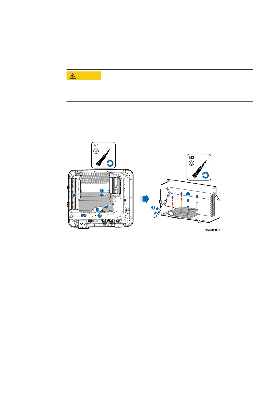
CA UTION
SUN2000-(12KTL-25KTL)-M5 Series
User Manual 8 Maintenance
8.4 Replacing a Fan
Procedure
Step 1 Remove the fan cover, disconnect fan cables, and remove the faulty fan.
● Before replacing a fan, power
● When replacing a fan, use insulated tools and wear PPE.
Figure 8-1 Removing a faulty fan
o the inverter.
Step 2 Install a new fan, connect and bind the cables, and install the fan cover.
----End
Issue 03 (2023-02-15) Copyright © Huawei Digital Power Technologies Co., Ltd. 77
Page 84
NO TICE
SUN2000-(12KTL-25KTL)-M5 Series
User Manual 9 Handling the Inverter
9 Handling the Inverter
9.1 Removing the SUN2000
Before removing the SUN2000, disconnect both AC and DC connections.
Perform the following operations to remove the SUN2000:
1. Disconnect all cables from the SUN2000, including RS485 communications
cables, DC input power cables, AC output power cables, and PGND cables.
2. Remove the SUN2000 from the mounting bracket.
3. Remove the mounting bracket.
9.2 Packing the SUN2000
● If the original packing materials are available, put the SUN2000 inside them
and then seal them by using adhesive tape.
● If the original packing materials are not available, put the SUN2000 inside a
suitable cardboard box and seal it properly.
9.3 Disposing of the SUN2000
If the SUN2000 service life expires, dispose of it according to the local disposal
rules for electrical equipment waste.
Issue 03 (2023-02-15) Copyright © Huawei Digital Power Technologies Co., Ltd. 78
Page 85
SUN2000-(12KTL-25KTL)-M5 Series
User Manual 10 Technical Specications
10 Technical Specications
10.1 SUN2000-(15KTL-25KTL)-ZHM5 Technical
Specications
Eciency
Item
Maximum
eciency
Chinese eciency 97.4% 97.4% 97.6% 98.0%
SUN2000-15KTLZHM5
98.5% 98.5% 98.5% 98.5%
SUN2000-17KTLZHM5
SUN2000-20KTLZHM5
SUN2000-25KTLZHM5
Input
Item
Recommended
maximum input
DC power
Maximum input
voltage
Maximum input
current per MPPT
a
SUN2000-15KTLZHM5
22500 W 25500 W 30000 W 37500 W
1100 V
20 A (one PV string)/30 A (one MPPT)
SUN2000-17KTLZHM5
SUN2000-20KTLZHM5
SUN2000-25KTLZHM5
Maximum shortcircuit current per
MPPT
Minimum startup
voltage
Issue 03 (2023-02-15) Copyright © Huawei Digital Power Technologies Co., Ltd. 79
40 A
200 V
Page 86
SUN2000-(12KTL-25KTL)-M5 Series
User Manual 10 Technical Specications
Item SUN2000-15KTL-
ZHM5
MPPT voltage
range
Full-load MPPT
voltage range
Rated input
voltage
Maximum
number of inputs
Number of
MPPTs
Note a: The maximum input voltage is the maximum DC input voltage that the inverter can
withstand. If the input voltage exceeds this value, the inverter may be damaged.
200–1000 V
410–800 V 440–800 V 480–800 V 530–800 V
600 V
4
2
SUN2000-17KTLZHM5
SUN2000-20KTLZHM5
SUN2000-25KTLZHM5
Output
Item
Rated output
power
Maximum
apparent power
Maximum active
power (cosφ = 1)
Rated output
voltage
Maximum output
voltage at longterm operation
Rated output
current
SUN2000-15KTLZHM5
15000 W 17000 W 20000 W 25000 W
16500 VA 18700 VA 22000 VA 27500 VA
16500 W 18700 W 22000 W 27500 W
220 V/380 V, 3W/N+PE
230 V/400 V, 3W/N+PE
239.6 V/415 V, 3W/N+PE
See standards about the local power grid.
22.8 A/380 V
21.7 A/400 V
20.9 A/415 V
SUN2000-17KTLZHM5
25.8 A/380 V
24.5 A/400 V
23.7 A/415 V
SUN2000-20KTLZHM5
30.4 A/380 V
28.9 A/400 V
27.8 A/415 V
SUN2000-25KTLZHM5
38.0 A/380 V
36.1 A/400 V
34.8 A/415 V
Maximum output
current
Issue 03 (2023-02-15) Copyright © Huawei Digital Power Technologies Co., Ltd. 80
25.2 A/380 V
23.9 A/400 V
23.1 A/415 V
28.6 A/380 V
27.1 A/400 V
26.1 A/415 V
33.6 A/380 V
31.9 A/400 V
30.8 A/415 V
42.0 A/380 V
39.9 A/400 V
38.5 A/415 V
Page 87
SUN2000-(12KTL-25KTL)-M5 Series
User Manual 10 Technical Specications
Item SUN2000-15KTL-
ZHM5
Output voltage
frequency
Power factor 0.8 leading... 0.8 lagging
Output DC
component DCI
Maximum total
harmonic
distortion AC
THDI
50 Hz/60 Hz
< 0.25% of the rated output
< 3% under rated conditions. Single-order harmonic meets the VDE4105
requirements.
SUN2000-17KTLZHM5
Protection
Item SUN2000-15KTL-
ZHM5
Overvoltage
category
PV II/AC III
SUN2000-17KTLZHM5
SUN2000-20KTLZHM5
SUN2000-20KTLZHM5
SUN2000-25KTLZHM5
SUN2000-25KTLZHM5
Input DC switch Supported
Anti-islanding
protection
Output
overcurrent
protection
Input reverse
connection
protection
DC surge
protection
AC surge
protection
Insulation
resistance
detection
Residual current
monitoring unit
(RCMU)
Supported
Supported
Supported
TYPE II
CLASS II
Supported
Supported
Issue 03 (2023-02-15) Copyright © Huawei Digital Power Technologies Co., Ltd. 81
Page 88
SUN2000-(12KTL-25KTL)-M5 Series
User Manual 10 Technical Specications
Display and Communication
Item SUN2000-15KTL-
ZHM5
Display LED indicators; WLAN+app
WLAN/FE Dongle Supported
4G Dongle Supported
RS485
communication
Built-in WLAN Supported
DC MBUS Supported
AFCI Supported
PID recovery Supported
Supported
SUN2000-17KTLZHM5
General
Item
SUN2000-15KTLZHM5
SUN2000-17KTLZHM5
SUN2000-20KTLZHM5
SUN2000-20KTLZHM5
SUN2000-25KTLZHM5
SUN2000-25KTLZHM5
Dimensions (H x
W x D)
Net weight 21 kg
Operating
temperature
Relative humidity 0–100%
Cooling mode Smart air cooling
Maximum
operating
altitude
Storage
temperature
IP rating IP66
Topology Transformerless
460 mm x 546 mm x 228 mm
–25°C to +60°C
4000 m (derated when the altitude is greater than 2000 m)
–40°C to +70°C
Issue 03 (2023-02-15) Copyright © Huawei Digital Power Technologies Co., Ltd. 82
Page 89
SUN2000-(12KTL-25KTL)-M5 Series
User Manual 10 Technical Specications
Wireless Communication Parameters
Specications Inverter Built-
in WiFi
Frequency 2400–2483.5
MHz
WLAN-FE Smart
Dongle
SDongleA-05:
2400–2483.5
MHz
4G Smart Dongle
SDongleA-03-CN:
● Supports LTE-FDD: B1/B3/B8.
● Supports LTE-TDD: B38/B39/B40/B41.
● Supports DC-HSPA+/HSPA+/HSPA/
UMTS: B1/B5/B8/B9.
● Supports TD-SCDMA: B34/B39.
● Supports GSM/GPRS/EDGE: 900 MHz/
1800 MHz.
SDongleB-03-CN:
● Supports LTE-FDD: B1/B3/B5/B8.
● Supports LTE-TDD: B34/B38/B39/B40/
B41.
● Supports GSM/GPRS/EDGE: 900 MHz/
1800 MHz.
SDongleB-06-CN (WiFi): 2400–2483.5
MHz
SDongleB-06-CN (4G):
● Supports LTE-FDD: B1/B3/B5/B8.
● Supports LTE-TDD: B34/B38/B39/B40/
B41.
● Supports GSM/GPRS/EDGE: 900 MHz/
1800 MHz.
Issue 03 (2023-02-15) Copyright © Huawei Digital Power Technologies Co., Ltd. 83
Page 90
SUN2000-(12KTL-25KTL)-M5 Series
User Manual 10 Technical Specications
Specications Inverter Built-
in WiFi
Protocol
standard
WLAN
802.11b/g/n
WLAN-FE Smart
Dongle
SDongleA-05:
WLAN
802.11b/g/n
4G Smart Dongle
SDongleA-03-CN:
● Supports LTE-FDD (with receive
diversity): B1/B3/B5/B8.
● Supports LTE-TDD (with receive
diversity): B34/B38/B39/B40/B41.
● Supports WCDMA: B1/B5/B8.
● Supports GSM: 900 MHz/1800 MHz.
● Supports digital audio.
SDongleB-03-CN:
● Supports LTE-FDD (with receive
diversity): B1/B3/B5/B8.
● Supports LTE-TDD (with receive
diversity): B34/B38/B39/B40/B41.
● Supports GSM: 900 MHz/1800 MHz.
● Supports digital audio.
SDongleB-06-CN (WiFi): WLAN
802.11b/g/n
SDongleB-06-CN (4G):
● Supports LTE-FDD (with receive
diversity): B1/B3/B5/B8.
● Supports LTE-TDD (with receive
diversity): B34/B38/B39/B40/B41.
● Supports GSM: 900 MHz/1800 MHz.
● Supports digital audio.
Issue 03 (2023-02-15) Copyright © Huawei Digital Power Technologies Co., Ltd. 84
Page 91
SUN2000-(12KTL-25KTL)-M5 Series
User Manual 10 Technical Specications
Specications Inverter Built-
in WiFi
Bandwidth 20 MHz/40 MHz
(optional)
WLAN-FE Smart
Dongle
20 MHz/40 MHz
(optional)
4G Smart Dongle
LTE features:
● Supports a maximum of 3GPP R8 nonCA Cat 4 FDD and TDD.
● Supports 1.4 MHz/3 MHz/5 MHz/10
MHz/15 MHz/20 MHz RF bandwidth.
● Supports MIMO in the downlink.
● LTE-FDD: maximum downlink rate of
150 Mbit/s and maximum uplink rate
of 50 Mbit/s
● LTE-TDD: maximum downlink rate of
130 Mbit/s and maximum uplink rate
of 30 Mbit/s
UMTS features:
● Supports 3GPP R7 HSDPA+, HSDPA,
HSUPA, and WCDMA.
● Supports QPSK and 16QAM
modulation.
● HSDPA+: maximum downlink rate of
21 Mbit/s
● HSUPA: maximum uplink rate of 5.76
Mbit/s
● WCDMA: maximum downlink rate of
384 kbit/s and maximum uplink rate
of 384 kbit/s
GSM features:
GPRS:
● Supports GPRS multislot class 12.
● Coding schemes: CS-1, CS-2, CS-3, and
CS-4
● Maximum downlink rate: 85.6 kbit/s;
maximum uplink rate: 85.6 kbit/s
EDGE:
● Supports EDGE multislot class 12.
● Supports GMSK and 8-PSK modulation
and coding schemes.
● Downlink coding format: MCS 1–9
● Uplink coding format: MCS 1–9
● Maximum downlink rate: 236.8 kbit/s;
maximum uplink rate: 236.8 kbit/s
SDongleB-06-CN (WiFi): 20 MHz/40 MHz
(optional)
Issue 03 (2023-02-15) Copyright © Huawei Digital Power Technologies Co., Ltd. 85
Page 92
SUN2000-(12KTL-25KTL)-M5 Series
User Manual 10 Technical Specications
Specications Inverter Built-
in WiFi
Maximum
transmit power
≤ 20 dBm EIRP ≤ 20 dBm EIRP ● Class 4 (33 dBm±2 dB), EGSM900
WLAN-FE Smart
Dongle
4G Smart Dongle
frequency band
● Class 1 (30 dBm±2 dB), DCS1800
frequency band
● Class E2 (27 dBm±3 dB), EGSM900 8PSK
● Class E2 (26 dBm±3 dB), DCS1800 8PSK
● Class 3 (24 dBm+1/–3 dB), WCDMA
frequency band
● Class 3 (23 dBm±2 dB), LTE-FDD
frequency band
● Class 3 (23 dBm±2 dB), LTE-TDD
frequency band
SDongleB-06-CN (WiFi): ≤ 20 dBm EIRP
10.2 SUN2000-(12KTL-25KTL)-M5 Technical
Specications
Eciency
Item
Maximum
eciency
European
eciency
Input
Item
Recommende
d maximum
input DC
power
SUN2000-12K
TL-M5
98.4% 98.4% 98.4% 98.4% 98.4%
97.9% 98.0% 98.1% 98.1% 98.2%
SUN2000-12K
TL-M5
18000 W 22500 W 25500 W 30000 W 37500 W
SUN2000-15K
TL-M5
SUN2000-15K
TL-M5
SUN2000-17K
TL-M5
SUN2000-17K
TL-M5
SUN2000-20K
TL-M5
SUN2000-20K
TL-M5
SUN2000-25K
TL-M5
SUN2000-25K
TL-M5
Maximum
input voltage
Issue 03 (2023-02-15) Copyright © Huawei Digital Power Technologies Co., Ltd. 86
1100 V
a
Page 93
SUN2000-(12KTL-25KTL)-M5 Series
User Manual 10 Technical Specications
Item SUN2000-12K
TL-M5
Maximum
input current
per MPPT
Maximum
short-circuit
current per
MPPT
Minimum
startup
voltage
MPPT voltage
range
Full-load
MPPT voltage
range
Rated input
voltage
20 A (one PV string)/30 A (one MPPT)
40 A
200 V
200–1000 V
370–800 V 410–800 V 440–800 V 480–800 V 530–800 V
600 V
SUN2000-15K
TL-M5
SUN2000-17K
TL-M5
SUN2000-20K
TL-M5
SUN2000-25K
TL-M5
Maximum
number of
inputs
Number of
MPPTs
Note a: The maximum input voltage is the maximum DC input voltage that the inverter can
withstand. If the input voltage exceeds this value, the inverter may be damaged.
4
2
Output
Item
Rated output
power
Maximum
apparent
power
Maximum
active power
(cosφ = 1)
SUN2000-12K
TL-M5
12000 W 15000 W 17000 W 20000 W 25000 W
13200 VA 16500 VA 18700 VA 22000 VA 27500 VA
13200 W 16500 W 18700 W 22000 W 27500 W
SUN2000-15K
TL-M5
SUN2000-17K
TL-M5
SUN2000-20K
TL-M5
SUN2000-25K
TL-M5
Issue 03 (2023-02-15) Copyright © Huawei Digital Power Technologies Co., Ltd. 87
Page 94
SUN2000-(12KTL-25KTL)-M5 Series
User Manual 10 Technical Specications
Item SUN2000-12K
TL-M5
Rated output
voltage
Maximum
output
voltage at
long-term
operation
Rated output
current
Maximum
output current
Output
voltage
frequency
220 V/380 V, 3W/N+PE
230 V/400 V, 3W/N+PE
239.6 V/415 V, 3W/N+PE
See standards about the local power grid.
18.2 A/380 V
17.3 A/400 V
16.7 A/415 V
20.2 A/380 V
19.1 A/400 V
18.5 A/415 V
50 Hz/60 Hz
SUN2000-15K
TL-M5
22.8 A/380 V
21.7 A/400 V
20.9 A/415 V
25.2 A/380 V
23.9 A/400 V
23.1 A/415 V
SUN2000-17K
TL-M5
25.8 A/380 V
24.5 A/400 V
23.7 A/415 V
28.6 A/380 V
27.1 A/400 V
26.1 A/415 V
SUN2000-20K
TL-M5
30.4 A/380 V
28.9 A/400 V
27.8 A/415 V
33.6 A/380 V
31.9 A/400 V
30.8 A/415 V
SUN2000-25K
TL-M5
38.0 A/380 V
36.1 A/400 V
34.8 A/415 V
42.0 A/380 V
39.9 A/400 V
38.5 A/415 V
Power factor 0.8 leading ... 0.8 lagging
Output DC
component
DCI
Maximum
total
harmonic
distortion AC
THDI
< 0.25% of the rated output
< 3% under rated conditions. Single-order harmonic meets the VDE4105
requirements.
Protection
Item
Overvoltage
category
Input DC
switch
SUN2000-12K
TL-M5
PV II/AC III
Supported
SUN2000-15K
TL-M5
SUN2000-17K
TL-M5
SUN2000-20K
TL-M5
SUN2000-25K
TL-M5
Anti-islanding
protection
Issue 03 (2023-02-15) Copyright © Huawei Digital Power Technologies Co., Ltd. 88
Supported
Page 95
SUN2000-(12KTL-25KTL)-M5 Series
User Manual 10 Technical Specications
Item SUN2000-12K
TL-M5
Output
overcurrent
protection
Input reverse
connection
protection
DC surge
protection
AC surge
protection
Insulation
resistance
detection
Residual
current
monitoring
unit (RCMU)
Supported
Supported
TYPE II
CLASS II
Supported
Supported
SUN2000-15K
TL-M5
SUN2000-17K
TL-M5
SUN2000-20K
TL-M5
SUN2000-25K
TL-M5
Display and Communication
Item
Display LED indicators; WLAN+app
WLAN/FE
Dongle
4G Dongle Optional
RS485
communicatio
n
Built-in WLAN Supported
DC MBUS Supported
AFCI Supported
PID recovery Supported
SUN2000-12K
TL-M5
Supported
Supported
SUN2000-15K
TL-M5
SUN2000-17K
TL-M5
SUN2000-20K
TL-M5
SUN2000-25K
TL-M5
Issue 03 (2023-02-15) Copyright © Huawei Digital Power Technologies Co., Ltd. 89
Page 96
SUN2000-(12KTL-25KTL)-M5 Series
User Manual 10 Technical Specications
General
Item SUN2000-12K
TL-M5
Dimensions
(H x W x D)
Net weight 21 kg
Operating
temperature
Relative
humidity
Cooling mode Smart air cooling
Maximum
operating
altitude
Storage
temperature
IP rating IP66
Topology Transformerless
460 mm x 546 mm x 228 mm
–25°C to +60°C
0–100%
4000 m (derated when the altitude is greater than 2000 m)
–40°C to +70°C
SUN2000-15K
TL-M5
SUN2000-17K
TL-M5
SUN2000-20K
TL-M5
SUN2000-25K
TL-M5
Wireless Communication Parameters
Specications
Frequency 2400–2483.5
Inverter Builtin WiFi
MHz
WLAN-FE Smart
Dongle
SDongleA-05:
2400–2483.5
MHz
4G Smart Dongle
SDongleA-03-EU:
● Supports LTE-FDD: B1/B3/B7/B8/B20.
● Supports LTE-TDD: B38/B40.
● Supports WCDMA/HSDPA/HSUPA/
HSPA+: B1/B8.
● Supports GSM/GPRS/EDGE: 900 MHz/
1800 MHz.
SDongleB-06-EU (WiFi): 2400–2483.5
MHz
SDongleB-06-EU (4G):
● Supports LTE-FDD: B1/B3/B5/B8.
● Supports LTE-TDD:
B7/B20/B28/B38/B40/B41.
● Supports GSM/GPRS/EDGE: 900 MHz/
1800 MHz.
Issue 03 (2023-02-15) Copyright © Huawei Digital Power Technologies Co., Ltd. 90
Page 97
SUN2000-(12KTL-25KTL)-M5 Series
User Manual 10 Technical Specications
Specications Inverter Built-
in WiFi
Protocol
standard
WLAN
802.11b/g/n
WLAN-FE Smart
Dongle
SDongleA-05:
WLAN
802.11b/g/n
4G Smart Dongle
SDongleA-03-EU:
● Supports LTE-FDD (with receive
diversity): B1/B3/B7/B8/B20/B28.
● Supports LTE-FDD (with receive
diversity): B38/B40/B41.
● Supports WCDMA: B1/B8.
● Supports GSM: 900 MHz/1800 MHz.
● Supports digital audio.
SDongleB-06-EU (WiFi): WLAN
802.11b/g/n
SDongleB-06-EU (4G):
● Supports LTE FDD (with receive
diversity): B1/B3/B5/B8.
● Supports LTE-TDD (with receive
diversity): B7/B20/B28/B38/B40/B41.
● Supports GSM: 900 MHz/1800 MHz.
● Supports digital audio.
Issue 03 (2023-02-15) Copyright © Huawei Digital Power Technologies Co., Ltd. 91
Page 98
SUN2000-(12KTL-25KTL)-M5 Series
User Manual 10 Technical Specications
Specications Inverter Built-
in WiFi
Bandwidth 20 MHz/40 MHz
(optional)
WLAN-FE Smart
Dongle
20 MHz/40 MHz
(optional)
4G Smart Dongle
LTE features:
● Supports a maximum of 3GPP R8 nonCA Cat 4 FDD and TDD.
● Supports 1.4 MHz/3 MHz/5 MHz/10
MHz/15 MHz/20 MHz RF bandwidth.
● Supports MIMO in the downlink.
● LTE-FDD: maximum downlink rate of
150 Mbit/s and maximum uplink rate
of 50 Mbit/s
● LTE-TDD: maximum downlink rate of
130 Mbit/s and maximum uplink rate
of 30 Mbit/s
UMTS features:
● Supports 3GPP R7 HSDPA+, HSDPA,
HSUPA, and WCDMA.
● Supports QPSK and 16QAM
modulation.
● HSDPA+: maximum downlink rate of
21 Mbit/s
● HSUPA: maximum uplink rate of 5.76
Mbit/s
● WCDMA: maximum downlink rate of
384 kbit/s and maximum uplink rate
of 384 kbit/s
GSM features:
GPRS:
● Supports GPRS multislot class 12.
● Coding schemes: CS-1, CS-2, CS-3, and
CS-4
● Maximum downlink rate: 85.6 kbit/s;
maximum uplink rate: 85.6 kbit/s
EDGE:
● Supports EDGE multislot class 12.
● Supports GMSK and 8-PSK modulation
and coding schemes.
● Downlink coding format: MCS 1–9
● Uplink coding format: MCS 1–9
● Maximum downlink rate: 236.8 kbit/s;
maximum uplink rate: 236.8 kbit/s
SDongleB-06-EU (WiFi): 20 MHz/40 MHz
(optional)
Issue 03 (2023-02-15) Copyright © Huawei Digital Power Technologies Co., Ltd. 92
Page 99
SUN2000-(12KTL-25KTL)-M5 Series
User Manual 10 Technical Specications
Specications Inverter Built-
in WiFi
Maximum
≤ 20 dBm EIRP ≤ 20 dBm EIRP ● Class 4 (33 dBm±2 dB), EGSM900
transmit power
WLAN-FE Smart
Dongle
4G Smart Dongle
frequency band
● Class 1 (30 dBm±2 dB), DCS1800
frequency band
● Class E2 (27 dBm±3 dB), EGSM900 8PSK
● Class E2 (26 dBm±3 dB), DCS1800 8PSK
● Class 3 (24 dBm+1/–3 dB), WCDMA
frequency band
● Class 3 (23 dBm±2 dB), LTE-FDD
frequency band
● Class 3 (23 dBm±2 dB), LTE-TDD
frequency band
SDongleB-06-EU (WiFi): ≤ 20 dBm EIRP
Issue 03 (2023-02-15) Copyright © Huawei Digital Power Technologies Co., Ltd. 93
Page 100
NO TE
SUN2000-(12KTL-25KTL)-M5 Series
User Manual A Grid Codes
A Grid Codes
The grid codes are subject to change. The listed codes are for reference only.
Table A-1 SUN2000-(15KTL-25KTL)-ZHM5 grid codes
No. Grid Code Description SUN2000-
15KTLZHM5
1 NB/T 32004 China Golden
Sun low-voltage
power grid
2 CHINA-LV220/380 China low-
voltage power
grid
Table A-2 SUN2000-(12KTL-25KTL)-M5 grid codes
No.
1 TAIPOWER Taiwan Power
Grid Code Description SUN20
low-voltage
power grid
Supported Supported Supported Supported
Supported Supported Supported Supported
00-12K
TL-M5
SupportedSupportedSupportedSupportedSupport
SUN2000
-17KTLZHM5
SUN200
0-15KTL
-M5
SUN200020KTLZHM5
SUN200
0-17KTL
-M5
SUN200
0-20KTL
-M5
SUN2000-2
5KTLZHM5
SUN200
0-25KTL
-M5
ed
2 OMAN Oman low-
voltage power
grid
3 Pakistan Pakistan power
grid
Issue 03 (2023-02-15) Copyright © Huawei Digital Power Technologies Co., Ltd. 94
SupportedSupportedSupportedSupportedSupport
ed
SupportedSupportedSupportedSupportedSupport
ed
 Loading...