

Page 1

SmartLogger2000-(10-C, 11-C)
User Manual
Issue
Draft A
Date
2017-02-15
HUAWEI TECHNOLOGIES CO., LTD.
Page 2

Issue Draft A (2017-02-15)
Huawei Proprietary and Confidential
Copyright © Huawei Technologies Co., Ltd.
i
Copyright © Huawei Technologies Co., Ltd. 2017. All rights reserved.
No part of this document may be reproduced or transmitted in any form or by any means without prior
written consent of Huawei Technologies Co., Ltd.
Trademarks and Permissions
and other Huawei trademarks are trademarks of Huawei Technologies Co., Ltd.
All other trademarks and trade names mentioned in this document are the property of their respective
holders.
Notice
The purchased products, services and features are stipulated by the contract made between Huawei and
the customer. All or part of the products, services and features described in this document may not be
within the purchase scope or the usage scope. Unless otherwise specified in the contract, all statements,
information, and recommendations in this document are provided "AS IS" without warranties, guarantees or
representations of any kind, either express or implied.
The information in this document is subject to change without notice. Every effort has been made in the
preparation of this document to ensure accuracy of the contents, but all statements, information, and
recommendations in this document do not constitute a warranty of any kind, express or implied.
Huawei Technologies Co., Ltd.
Address:
Huawei Industrial Base
Bantian, Longgang
Shenzhen 518129
People's Republic of China
Website:
http://www.huawei.com
Email:
Page 3
SmartLogger2000-(10-C, 11-C)
User Manual
About This Document
Issue Draft A (2017-02-15)
Huawei Proprietary and Confidential
Copyright © Huawei Technologies Co., Ltd.
ii
Overview
Symbol
Description
Indicates an imminently hazardous situation which, if not
avoided, will result in death or serious injury.
Indicates a potentially hazardous situation which, if not
avoided, could result in death or serious injury.
Indicates a potentially hazardous situation which, if not
avoided, may result in minor or moderate injury.
About This Document
This document introduces the SmartLogger2000-10-C/SmartLogger2000-11-C
(SmartLogger for short) in terms of installation, cable connections, system operation and
maintenance, and troubleshooting. Readers should understand the SmartLogger features,
functions, and safety precautions provided in this document before installing and operating
the SmartLogger.
The figures provided in this document are for reference only. The actual product appearance
prevails.
You can print the document based on your requirements. Store the paper copy properly for
future use. You can log in to http://support.huawei.com/carrier/, click Product Support, and
search for SmartLogger to view and obtain the latest user manual.
Intended Audience
This document is intended for photovoltaic (PV) plant operators and qualified electrical
technical personnel.
Symbol Conventions
The symbols that may be found in this document are defined as follows.
Page 4
SmartLogger2000-(10-C, 11-C)
User Manual
About This Document
Issue Draft A (2017-02-15)
Huawei Proprietary and Confidential
Copyright © Huawei Technologies Co., Ltd.
iii
Symbol
Description
Indicates a potentially hazardous situation which, if not
avoided, could result in equipment damage, data loss,
performance deterioration, or unanticipated results.
NOTICE is used to address practices not related to personal
injury.
Calls attention to important information, best practices and
tips.
NOTE is used to address information not related to personal
injury, equipment damage, and environment deterioration.
Change History
Changes between document issues are cumulative. The latest document issue contains all the
changes made in earlier issues.
Issue Draft A (2017-02-15)
This issue is used for first office application (FOA).
Page 5

SmartLogger2000-(10-C, 11-C)
User Manual
Contents
Issue Draft A (2017-02-15)
Huawei Proprietary and Confidential
Copyright © Huawei Technologies Co., Ltd.
iv
Contents
About This Document .................................................................................................................... ii
1 Safety Precautions ......................................................................................................................... 1
2 Product Overview ......................................................................................................................... 3
2.1 Overview ...................................................................................................................................................................... 3
2.2 Appearance ................................................................................................................................................................... 6
2.3 Nameplate Description ............................................................................................................................................... 10
2.4 Typical Networking Scenarios .................................................................................................................................... 12
2.5 System Wiring Diagram.............................................................................................................................................. 14
3 Device Installation ...................................................................................................................... 23
3.1 Precautions .................................................................................................................................................................. 23
3.2 Checking Before Installation ...................................................................................................................................... 23
3.3 Tools ........................................................................................................................................................................... 24
3.4 Determining the Installation Position ......................................................................................................................... 26
3.5 Installing a SmartLogger ............................................................................................................................................ 28
3.5.1 Installing a SmartLogger on a Wall ......................................................................................................................... 28
3.5.2 Installing a SmartLogger Along a Guide Rail .......................................................................................................... 31
4 Electrical Connection .................................................................................................................. 35
4.1 Precautions .................................................................................................................................................................. 35
4.2 Preparing an OT Terminal........................................................................................................................................... 35
4.3 Connecting Cables to the Terminal Block on the COM Port ...................................................................................... 36
4.4 Connecting a PE Cable to the SmartLogger ............................................................................................................... 37
4.5 Connecting the SUN2000 ........................................................................................................................................... 38
4.5.1 Connection Description ........................................................................................................................................... 38
4.5.2 Connecting the SUN2000 Over RS485 ................................................................................................................... 38
4.5.3 Connecting the SUN2000 Through AC Power Cables ............................................................................................ 44
4.5.4 Connecting Multiple SUN2000s .............................................................................................................................. 45
4.6 Connecting an EMI ..................................................................................................................................................... 47
4.6.1 Connection Description ........................................................................................................................................... 47
4.6.2 Connecting the SmartLogger to an EMI That Supports Standard Modbus-RTU ..................................................... 47
4.6.3 Connecting the SmartLogger to a Split EMI ........................................................................................................... 48
4.7 Connecting a Power Meter ......................................................................................................................................... 53
Page 6

SmartLogger2000-(10-C, 11-C)
User Manual
Contents
Issue Draft A (2017-02-15)
Huawei Proprietary and Confidential
Copyright © Huawei Technologies Co., Ltd.
v
4.8 Connecting a Box-type Transformer ........................................................................................................................... 54
4.9 Connecting a PID Module .......................................................................................................................................... 55
4.10 Connecting a Ripple Control Receiver ..................................................................................................................... 57
4.11 Connecting an Ethernet Network Cable .................................................................................................................... 60
4.12 Connecting Fiber Jumpers ........................................................................................................................................ 61
5 System Operation ........................................................................................................................ 63
5.1 Checking Before Power-On ........................................................................................................................................ 63
5.2 System Power-On ....................................................................................................................................................... 64
6 Man-Machine Interaction .......................................................................................................... 65
6.1 USB Flash Drive Operation ........................................................................................................................................ 65
6.1.1 Exporting Data ......................................................................................................................................................... 65
6.1.2 Exporting All Files ................................................................................................................................................... 66
6.1.3 Importing All Files ................................................................................................................................................... 68
6.1.4 Upgrading the Application ....................................................................................................................................... 69
6.1.5 Upgrading the BSP .................................................................................................................................................. 70
6.2 NMS Operation ........................................................................................................................................................... 71
6.3 App Operation ............................................................................................................................................................. 71
7 WebUI............................................................................................................................................ 72
7.1 Note ............................................................................................................................................................................ 72
7.2 Preparations for Login ................................................................................................................................................ 72
7.3 Logging In to the WebUI ............................................................................................................................................ 80
7.4 Icon Description.......................................................................................................................................................... 81
7.5 WebUI Layout ............................................................................................................................................................. 82
7.6 Overview .................................................................................................................................................................... 83
7.6.1 Plant Running Information ...................................................................................................................................... 83
7.6.2 Active Alarm ............................................................................................................................................................ 83
7.6.3 Plant Yield................................................................................................................................................................ 84
7.6.4 Performance Data .................................................................................................................................................... 85
7.6.5 Device Running Information ................................................................................................................................... 85
7.7 Device Monitoring ...................................................................................................................................................... 86
7.7.1 Querying Device Status ........................................................................................................................................... 86
7.7.2 SmartLogger ............................................................................................................................................................ 86
7.7.2.1 Querying Master SmartLogger-Related Information ............................................................................................ 86
7.7.2.2 Querying Slave SmartLogger-Related Information .............................................................................................. 87
7.7.3 SUN2000 ................................................................................................................................................................. 88
7.7.3.1 Querying Related Information .............................................................................................................................. 88
7.7.3.2 Setting Running Parameters (Advanced User) ..................................................................................................... 88
7.7.3.3 Setting Running Parameters (Special User) ................................................................ ................................ .......... 99
7.7.3.4 Setting a Tracking System .................................................................................................................................. 109
7.7.3.5 Setting the LVRT Characteristic Curve ............................................................................................................... 110
7.7.4 PLC ........................................................................................................................................................................ 110
Page 7

SmartLogger2000-(10-C, 11-C)
User Manual
Contents
Issue Draft A (2017-02-15)
Huawei Proprietary and Confidential
Copyright © Huawei Technologies Co., Ltd.
vi
7.7.4.1 Querying Related Information ............................................................................................................................ 110
7.7.4.2 Setting the STA List ............................................................................................................................................ 111
7.7.4.3 Networking Settings ........................................................................................................................................... 112
7.7.5 EMI ................................ ................................................................................................ ................................ ........ 113
7.7.5.1 Querying Related Information ............................................................................................................................ 113
7.7.5.2 Setting Running Parameters ................................................................................................................................ 114
7.7.6 Power Meter........................................................................................................................................................... 117
7.7.6.1 Querying Related Information ............................................................................................................................ 117
7.7.6.2 Setting Running Parameters ................................................................................................................................ 118
7.7.7 PID ......................................................................................................................................................................... 119
7.7.7.1 Querying Related Information ............................................................................................................................ 119
7.7.7.2 Setting Running Parameters ................................................................................................................................ 120
7.7.8 Custom Device....................................................................................................................................................... 124
7.7.8.1 Querying Related Information ............................................................................................................................ 124
7.7.8.2 Setting Telecontrol Parameters ........................................................................................................................... 125
7.7.8.3 Setting Teleadjust Parameters ............................................................................................................................. 126
7.7.9 IEC103 Device....................................................................................................................................................... 127
7.7.9.1 Querying Related Information ............................................................................................................................ 127
7.7.9.2 Setting Telecontrol Parameters ........................................................................................................................... 127
7.7.9.3 Setting Teleadjust Parameters ............................................................................................................................. 128
7.8 Querying Historical Data .......................................................................................................................................... 129
7.8.1 Querying Historical Alarms ................................................................................................................................... 129
7.8.2 Querying Operation Logs ...................................................................................................................................... 129
7.8.3 Exporting Data ....................................................................................................................................................... 130
7.9 Settings ..................................................................................................................................................................... 132
7.9.1 User Parameters ..................................................................................................................................................... 132
7.9.1.1 Setting the Date and Time ................................................................................................................................... 132
7.9.1.2 Setting Plant Information .................................................................................................................................... 133
7.9.1.3 Setting Gain Parameters ...................................................................................................................................... 134
7.9.1.4 Setting the Saving Interval .................................................................................................................................. 135
7.9.2 Communications Parameters ................................................................................................................................. 135
7.9.2.1 Setting Ethernet Parameters ................................................................................................................................ 135
7.9.2.2 Setting RS485 Parameters .................................................................................................................................. 136
7.9.2.3 Setting Power Meter Parameters ......................................................................................................................... 137
7.9.2.4 Setting NetEco Parameters ................................................................................................................................. 139
7.9.2.5 Setting Modbus TCP Parameters ........................................................................................................................ 140
7.9.2.6 Setting IEC103 Parameters ................................................................................................................................. 141
7.9.2.7 Setting IEC104 Parameters ................................................................................................................................. 142
7.9.3 Extended Parameters.............................................................................................................................................. 143
7.9.3.1 Setting FTP Parameters ....................................................................................................................................... 143
7.9.3.2 Setting Email Parameters .................................................................................................................................... 144
7.9.4 Port Settings ........................................................................................................................................................... 145
Page 8

SmartLogger2000-(10-C, 11-C)
User Manual
Contents
Issue Draft A (2017-02-15)
Huawei Proprietary and Confidential
Copyright © Huawei Technologies Co., Ltd.
vii
7.9.4.1 Setting DO Parameters ........................................................................................................................................ 145
7.9.4.2 Setting USB Parameters ...................................................................................................................................... 147
7.9.5 Remotely Shutting Down SUN2000s in Dry Contact Mode ................................................................................. 148
7.9.6 Setting DI Parameters ............................................................................................................................................ 151
7.10 Maintenance ............................................................................................................................................................ 152
7.10.1 Firmware Upgrade ............................................................................................................................................... 152
7.10.2 Product Information ............................................................................................................................................. 153
7.10.3 Setting Security Parameters ................................................................................................................................. 153
7.10.4 System Maintenance ............................................................................................................................................ 154
7.10.5 Device Log........................................................................................................................................................... 155
7.10.6 Site Test ............................................................................................................................................................... 156
7.10.7 Device Management ............................................................................................................................................ 156
7.10.7.1 Connecting Devices .......................................................................................................................................... 156
7.10.7.2 Device List ........................................................................................................................................................ 158
7.10.7.3 Exporting Parameters ................................................................................................ ................................ ........ 158
7.10.7.4 Resetting Alarms ............................................................................................................................................... 159
7.10.7.5 Re-collecting Performance Data ....................................................................................................................... 160
7.10.7.6 Correcting the Total Energy Yield..................................................................................................................... 161
8 Power Grid Scheduling............................................................................................................ 163
8.1 Power Grid Dispatching Modes ................................................................................................................................ 163
8.1.1 Active Power Control............................................................................................................................................. 163
8.1.2 Reactive Power Control ......................................................................................................................................... 164
8.2 Application Scenarios ............................................................................................................................................... 165
8.2.1 Local Scheduling ................................................................................................................................................... 165
8.2.2 Dry Contact Scheduling ......................................................................................................................................... 171
8.2.3 AI/DI Scheduling ................................................................................................................................................... 174
8.2.4 Communication Scheduling ................................................................................................................................... 177
9 Device Maintenance ................................................................................................................. 181
9.1 Routine Maintenance ................................................................................................ ................................................ 181
9.2 Troubleshooting ........................................................................................................................................................ 181
9.3 Alarm List ................................................................................................................................................................. 183
10 SmartLogger Disposal ............................................................................................................ 188
11 Technical Specifications ........................................................................................................ 189
A Product User Lists .................................................................................................................... 192
B Certification Declaration ......................................................................................................... 193
C Acronyms and Abbreviations ................................................................................................ 195
Page 9

SmartLogger2000-(10-C, 11-C)
User Manual
1 Safety Precautions
Issue Draft A (2017-02-15)
Huawei Proprietary and Confidential
Copyright © Huawei Technologies Co., Ltd.
1
Read the safety precautions carefully. Otherwise, human injury and equipment damage may
occur.
Personnel Requirements
Only qualified and trained electrical technicians are allowed to install and operate the
SmartLogger.
Operators should understand the components and functioning of a grid-tied PV power
system, and they should be familiar with relevant local standards.
1 Safety Precautions
Read this document thoroughly before operations. Huawei shall not be liable for any
consequence caused by violation of the storage, transportation, installation, and operation
regulations specified in this document.
Label Protection
Installation
Do not tamper with any signs on the SmartLogger enclosure because these signs contain
important information about safe operation.
Do not remove or damage the nameplate at the rear of the SmartLogger enclosure
because it contains important product information.
Ensure that the SmartLogger is not connected to a power supply and is not powered on
before starting installation.
Install the SmartLogger in an environment with good ventilation to ensure efficient and
long-term system performance.
Ensure that the heat dissipation holes of the SmartLogger are not blocked.
During installation, do not touch any component inside the enclosure except the wiring
terminals at the bottom.
Install the SmartLogger in a dedicated area.
Page 10

SmartLogger2000-(10-C, 11-C)
User Manual
1 Safety Precautions
Issue Draft A (2017-02-15)
Huawei Proprietary and Confidential
Copyright © Huawei Technologies Co., Ltd.
2
Operation
Perform operations in strict accordance with safety precautions specified in this document and
other relevant documents.
When operating Huawei equipment, you must follow the local laws and regulations.
Maintenance and Replacement
A faulty SmartLogger requires overall maintenance. Contact the dealer if the
SmartLogger is faulty.
With sufficient knowledge of this document, maintain the SmartLogger by using proper
tools and testing equipment.
When maintaining the SmartLogger, wear electrostatic discharge (ESD) gloves and
comply with ESD precautions.
The device has multiple inputs. Switch off all inputs before maintenance.
Page 11

SmartLogger2000-(10-C, 11-C)
User Manual
2 Product Overview
Issue Draft A (2017-02-15)
Huawei Proprietary and Confidential
Copyright © Huawei Technologies Co., Ltd.
3
2.1 Overview
Function
The SmartLogger is a highly integrated device dedicated for monitoring and managing the PV
power system. It converges ports, converts protocols, collects and stores data, and centrally
monitors and maintains devices in the PV power system.
2 Product Overview
Features
The SmartLogger provides the following features:
Wide application
− Industrial-grade application, wide temperature range: –40°C to +60°C
− High altitude: applicable at an altitude of 4000 m
Various communication modes
− Bluetooth
Has a built-in Bluetooth module through which the SUN2000 APP (APP for short)
connects to the SmartLogger for parameter configuration and device maintenance.
The SmartLogger Bluetooth is named as LOG+the last eight figures of the SN of
the SmartLogger.
− Optical fiber ring switch
Provides two 100M Ethernet optical ports that support RSTP and STP to implement
fiber ring networking. If RSTP is used, fiber ring protection can be completed
within 10 seconds. If STP is used, fiber ring protection can be completed within 60
seconds.
− PLC
The SmartLogger-10-C has a built-in PLC CCO module through which
southbound devices connect to the SmartLogger over AC power cables.
The built-in PLC CCO module has the maximum voltage class of 800 V AC.
− Ethernet electrical port
Provides two 10/100M Ethernet electrical ports that can be used as southbound
ports to connect to southbound devices or used as northbound ports to connect to an
NMS.
Page 12

SmartLogger2000-(10-C, 11-C)
User Manual
2 Product Overview
Issue Draft A (2017-02-15)
Huawei Proprietary and Confidential
Copyright © Huawei Technologies Co., Ltd.
4
A southbound port connects to a downstream device for collecting data and setting parameters.
Southbound devices include the SUN2000, environmental monitoring instrument (EMI), power
meter, box-type transformer, and PID module.
A northbound port connects to an upstream NMS for uploading data.
− RS485
Supports six RS485 routes and access of devices that use Modbus-RTU,
IEC103, and DL/T645.
RS485 supports the modbus-slave mode. If RS485 is set to Modbus-Slave, the
SmartLogger works in slave mode and can interwork with a third-party device,
such as a data collector and a communication manager.
Graphical data
− In addition to displaying the electricity yield and real-time monitoring information
in graphic and text format, the embedded WebUI can also display performance data
of power stations and devices in tables or curves.
− The APP displays the electricity yield and real-time monitoring information in
graphic and text format.
Centralized monitoring
− Manages up to 200 devices in centralized mode and supports the access of up to 150
SUN2000s.
− Allows you to monitor and manage the PV power system on the embedded WebUI,
for example, viewing real-time information about power stations, devices, and
faults, setting device parameters, and maintaining devices in remote mode.
− Allows you to monitor the devices in the PV power system on the APP in real time,
such as viewing information about power stations, devices, products, and faults,
setting device parameters, and maintaining devices.
Easy maintenance
− Allows users to upgrade the firmware of the SmartLogger and export data by using
a USB flash drive.
− Allows you to upgrade the firmware of the SmartLogger, SUN2000, PLC module,
and PID module, and export logs and data over the embedded WebUI.
− Allows you to manage the devices connecting to the SmartLogger, upgrade the
firmware of these devices, exports data from these devices, and classify and query
alarms over the app.
Intelligent management
− Automatically searches for and accesses Huawei SUN2000s, PLC modules, and
PID modules. If you import a parameter configuration table, the SmartLogger can
access third-party devices that support Modbus-RTU and IEC103.
− Automatically assigns RS485 addresses to the connected Huawei SUN2000s and
PID modules, and allows for RS485 address adjustment based on ESNs to facilitate
remote configuration and maintenance.
− Supports remote configuration of SUN2000 parameters over the embedded WebUI
and synchronizes the parameters from one SUN2000 to other SUN2000s in batches.
− Automatically collects the data generated during the communication disconnection
from the SUN2000 or manually collects the data over the embedded WebUI after
the connection resumes.
Remote maintenance
Page 13
SmartLogger2000-(10-C, 11-C)
User Manual
2 Product Overview
Issue Draft A (2017-02-15)
Huawei Proprietary and Confidential
Copyright © Huawei Technologies Co., Ltd.
5
− Simultaneously connects to multiple NMSs (including Huawei and third-party
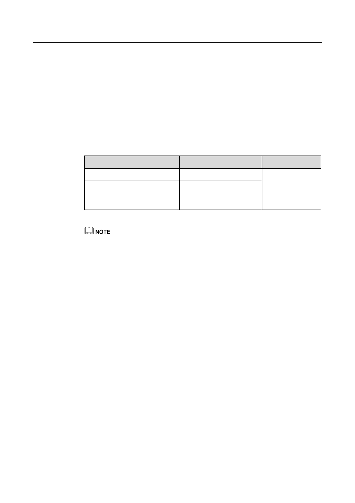
Model
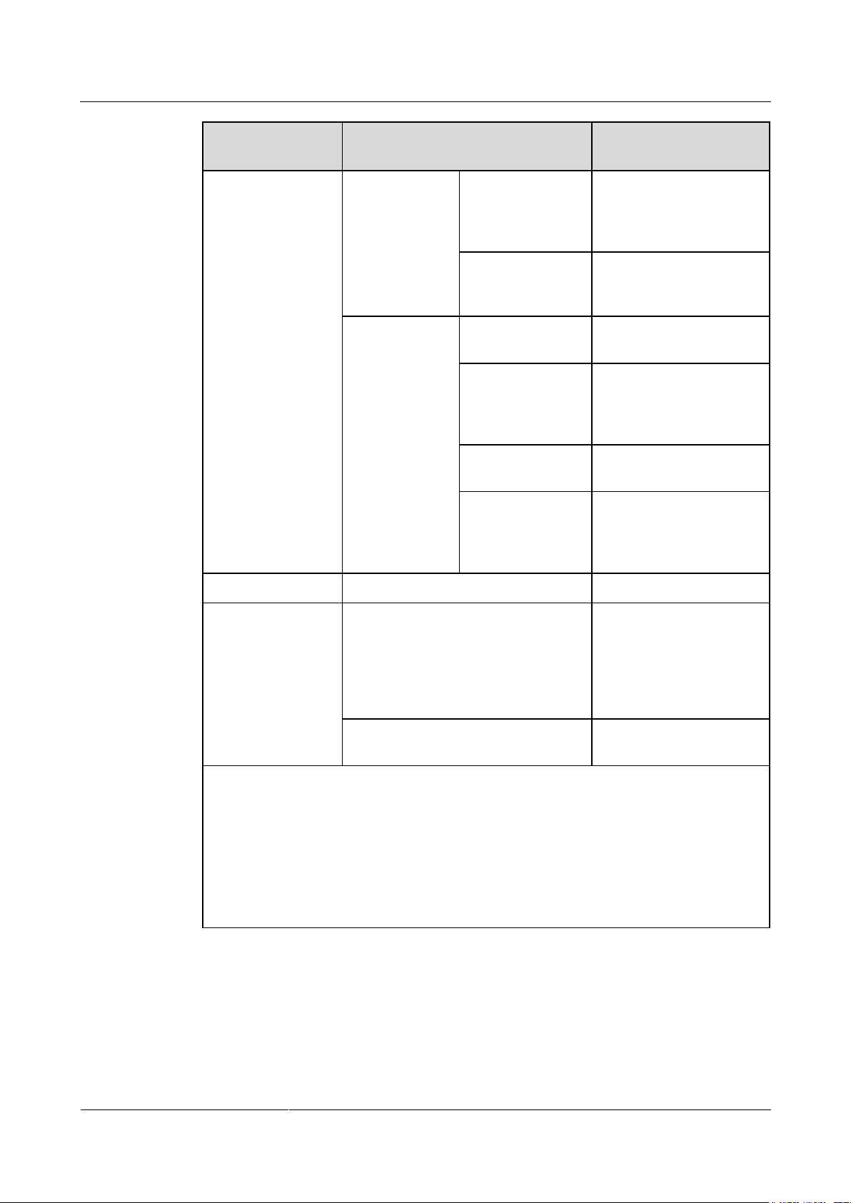
PLC Module Configured?
Remarks
SmartLogger2000-10-C
Yes
The built-in
Bluetooth module
supports both
Android APP and
iOS APP.
SmartLogger2000-11-C
No
− Supports connection to a third-party NMS over File Transfer Protocol (FTP).
− Sends electricity yield and alarms to users by emails.
Grid scheduling
− The SmartLogger supports various power grid scheduling modes and therefore can
− Implements rapid active power control and reactive power compensation for all the
Model Description
NMSs) over Modbus-TCP and IEC104. Huawei NMS features centralized O&M,
big data analytics, intelligent diagnosis, and mobile O&M.
meet the requirements of power grid companies in different countries.
SUN2000s connecting to the SmartLogger.
The SmartLogger2000-10-C is integrated with the PLC central coordinator (CCO) that can work
with the SUN2000 integrated with the PLC station (STA) to implement PLC networking over power
cables.
The SmartLogger2000-11-C is not integrated with the PLC CCO. If PLC networking with the
SUN2000 integrated with the PLC STA is required, connect a PLC CCO to the
SmartLogger2000-11-C.
This document describes the typical networking and cable connections by using the
SmartLogger2000-10-C as an example.
Page 14
SmartLogger2000-(10-C, 11-C)
User Manual
2 Product Overview
Issue Draft A (2017-02-15)
Huawei Proprietary and Confidential
Copyright © Huawei Technologies Co., Ltd.
6
2.2 Appearance
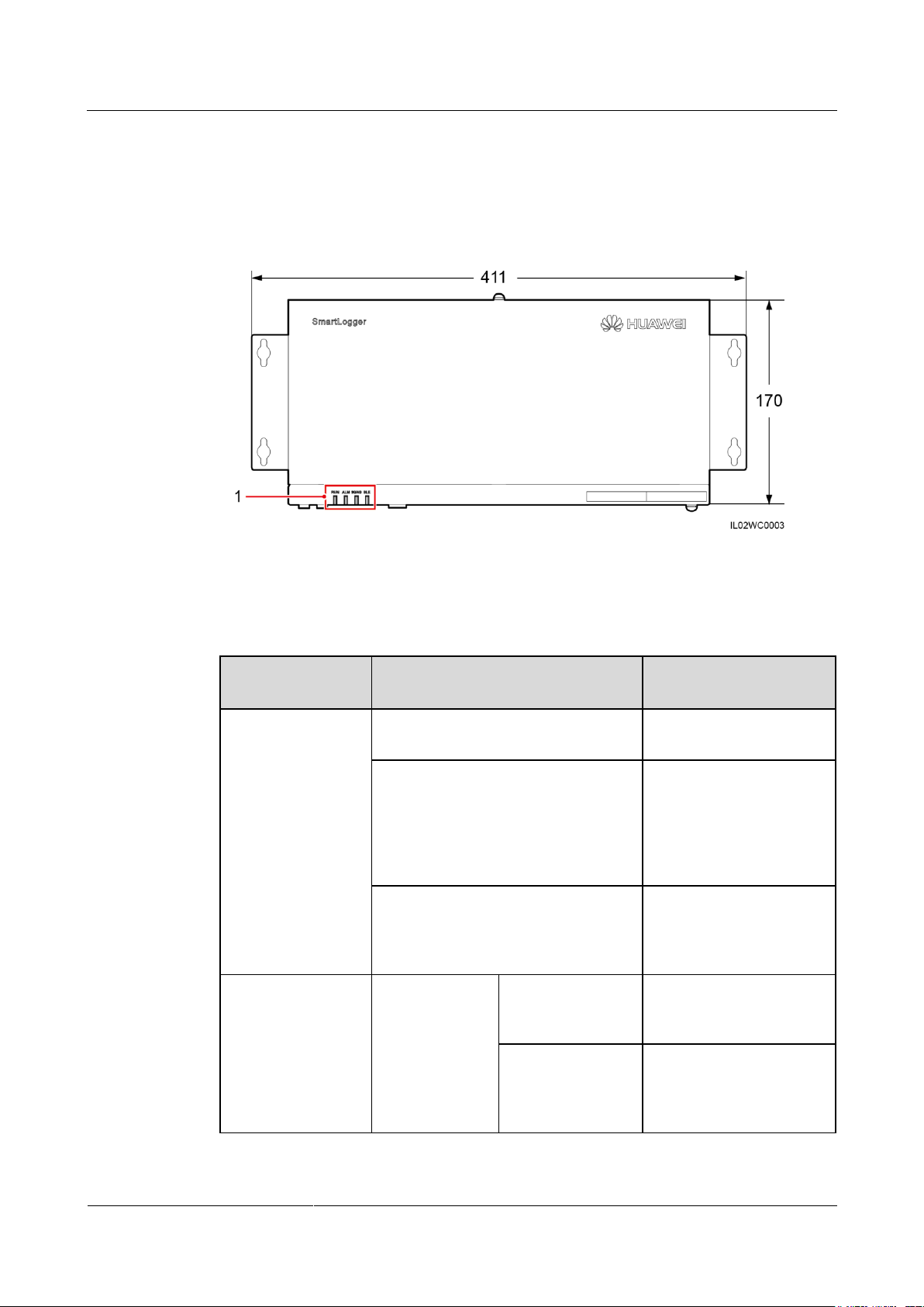
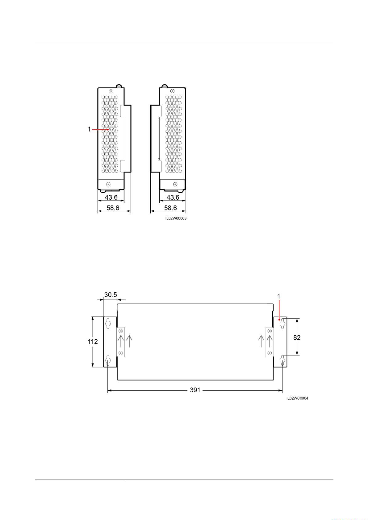
(1) Indicators
Indicator (Silk
Screen)
Status
Meaning
RUN indicator
Green off
The SmartLogger is not
powered on.
Blinking green at short intervals (on
for 0.125s and then off for 0.125s)
The SmartLogger and
NMS (Huawei NetEco or
a third-party NMS) are not
connected or the
communication between
them is interrupted.
Blinking green at long intervals (on
for 1s and then off for 1s)
The SmartLogger properly
communicates with the
NMS (Huawei NetEco or
a third-party NMS).
Alarm/maintenance
indicator (ALM)a
Alarm status
Red off
The SmartLogger and the
devices accessing it do not
generate any alarm.
Blinking red at
long intervals (on
for 1s and then off
for 4s)
The SmartLogger or the
devices accessing it
generate warnings.
Front View of the Shell
Figure 2-1 SmartLogger front view (unit: mm)
Table 2-1 Description of the LED indicators (from left to right)
Page 15
SmartLogger2000-(10-C, 11-C)
User Manual
2 Product Overview
Issue Draft A (2017-02-15)
Huawei Proprietary and Confidential
Copyright © Huawei Technologies Co., Ltd.
7
Indicator (Silk
Screen)
Status
Meaning
Blinking red at
short intervals (on
for 0.5s and then
off for 0.5s)
The SmartLogger or the
devices accessing it
generate minor alarms.
Steady red
The SmartLogger or the
devices accessing it
generate major alarms.
Maintenance
status
Green off
No local maintenance is
underwayb.
Blinking green at
long intervals (on
for 1s and then off
for 1s)
Local maintenance is in
progress.
Steady green
Local maintenance
succeeds.
Blinking green at
short intervals (on
for 0.125s and then
off for 0.125s)
Local maintenance fails.
3G/4G indicator
-
Reserved.
Bluetooth indicator
(BLE)
Green off
You have not logged in to
the APP or login failed.
The SmartLogger is not
connected to the APP or
the communication has
been interruptedc.
Blinking green at long intervals (on
for 1s and then off for 1s)
You have successfully
logged in to the APP.
a: If an alarm and local maintenance happen concurrently, the alarm/maintenance indicator
shows the near-end maintenance state first. After the USB flash drive is removed, the
indicator shows the alarm state.
b: Local maintenance refers to operations performed by connecting a USB flash drive to the
SmartLogger USB port, such as full data import and export using a USB flash drive.
c: After the communication between the SmartLogger and the APP fails, the disconnection
is normal if the green indicator goes off immediately, and is abnormal if the indicator goes
off after blinking slowly for 30s.
Page 16
SmartLogger2000-(10-C, 11-C)
User Manual
2 Product Overview
Issue Draft A (2017-02-15)
Huawei Proprietary and Confidential
Copyright © Huawei Technologies Co., Ltd.
8
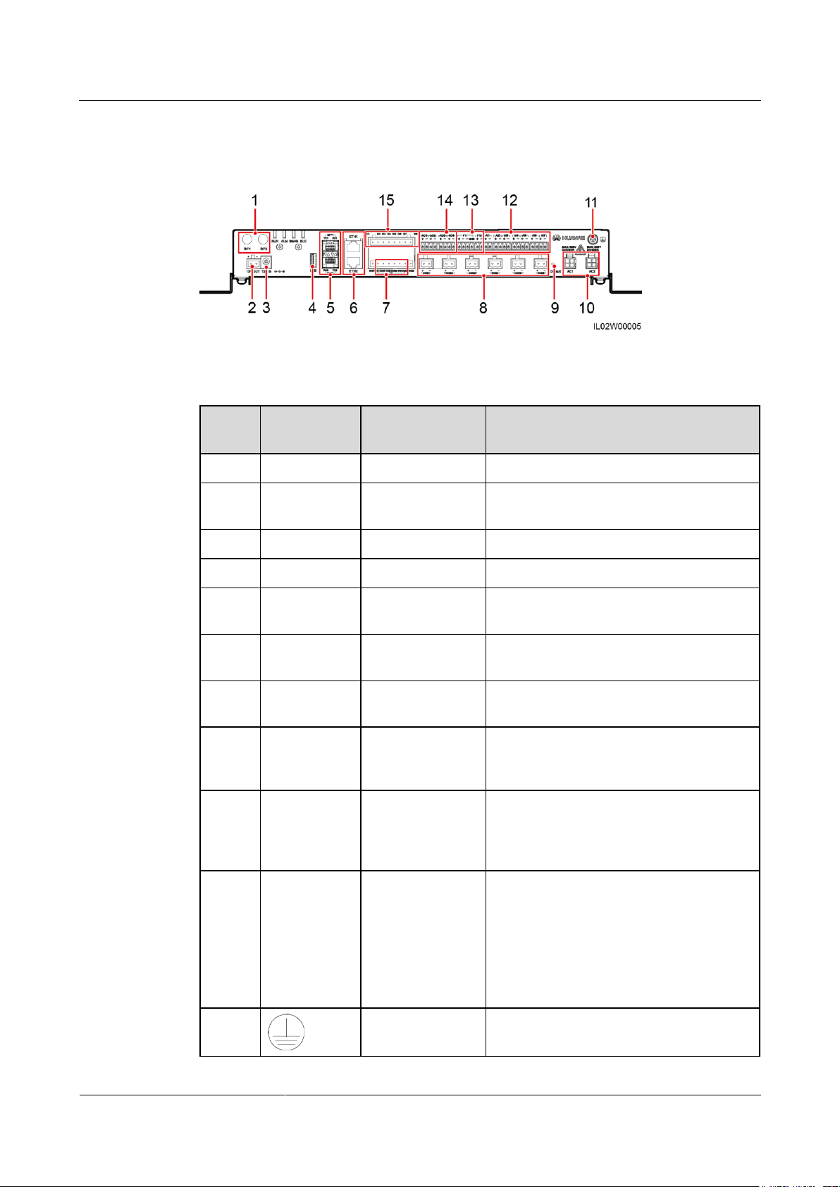
Side View of the Shell
(1) Heat dissipation hole
(1) Wall-mounting ears
Figure 2-2 SmartLogger side view (unit: mm)
Rear View of the Shell
Figure 2-3 SmartLogger rear view (unit: mm)
Page 17
SmartLogger2000-(10-C, 11-C)
User Manual
2 Product Overview
Issue Draft A (2017-02-15)
Huawei Proprietary and Confidential
Copyright © Huawei Technologies Co., Ltd.
9
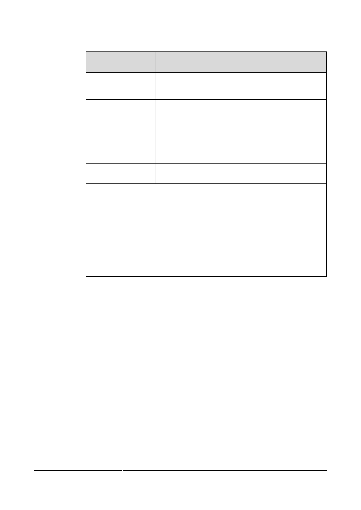
Bottom of the Shell
No.
Port (Silk
Screen)
Function
Description
1
RF1, RF2
Reserved
Reserved.
2
12V OUT
12 V DC output
Provides 12 V DC power supply with a
maximum current of 100 mA.
3
12V IN
12 V DC input
Connects to a power adapter.
4
USB
USB port
Connects a USB flash drive.
5
SFP1, SFP2
Ethernet optical
port
Connects to an ATB or another cascaded
SmartLogger.
6
ETH1, ETH2
Ethernet electrical
port
Connects to an Ethernet switch, router,
POE module, or PC.
7
DO
Digital parameter
output
Relay output.
8
COM1–COM
6
RS485
communication
Six RS485 ports that can be connected to
devices such as the SUN2000, box-type
transformer, power meter, or EMI.
9
Default
Default key
Resets and restarts the Bluetooth module or
resets the SmartLogger IP address to the
default IP addressa. The default IP address
is 192.168.0.10.
10
AC1, AC2
AC power cable
ports
SmartLogger2000-10-C: Connects to
the A/B/C three-phase input, and used
for PLC with the SUN2000 over AC
power cables. If PLC function is not
used, you do not have to connect cables
to these ports.
SmartLogger2000-11-C: left blank
11
External
grounding
N/A
Figure 2-4 Bottom view of the SmartLogger
Table 2-2 Port description
Page 18
SmartLogger2000-(10-C, 11-C)
User Manual
2 Product Overview
Issue Draft A (2017-02-15)
Huawei Proprietary and Confidential
Copyright © Huawei Technologies Co., Ltd.
10
No.
Port (Silk
Screen)
Function
Description
12
AI1–AI7
Analog input
AI1 supports 0–10 V voltage input
(passive); AI2–AI7 support 0–20 mA and
4–20 mA current input (passive).
13
PT1, PT2
Analog input
PT1 supports the connection to a
three-wire or two-wire PT100/PT1000
temperature sensor.
PT2 supports the connection to only a
two-wire PT100/PT1000 temperature
sensor.
13
AO1–AO4
Analog output
4–20 mA and 0–20 mA current output.
14
DI1–DI8
Digital parameter
input
Connects to a dry contact input.
a:
If the APP fails to connect to the SmartLogger or you have forgotten the IP address, you
can press the Default key to reset the Bluetooth module or restore the IP address to the
default IP address (192.168.0.10).
To reset and restart the Bluetooth module, press and hold down the Default key for
3–10s until the BLU indicator blinks at short intervals (0.125s on and 0.125s off) and all
other indicators are off, and then release the Default key.
To restore the IP address to the default IP address, press and hold down the Default key
for more than 10s until the RUN indicator blinks at short intervals (0.125s on and
0.125s off) and all other indicators are off, and then release the Default key. The
operation is valid within 5 minutes.
2.3 Nameplate Description
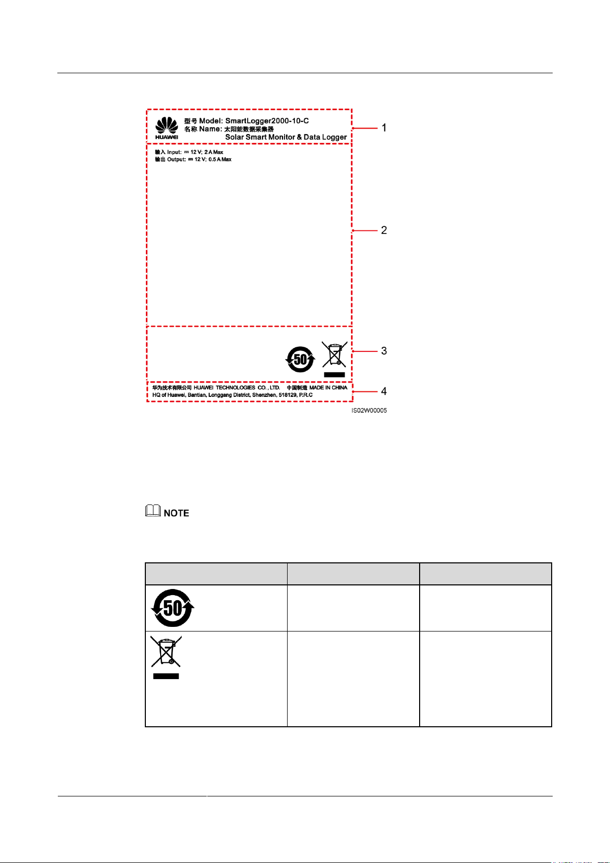
A nameplate is attached at the back of the SmartLogger. The content of the nameplate
includes the SmartLogger model, rated power specifications, and certification marks. Figure
2-5 shows the nameplate of the SmartLogger2000-10-C.
Page 19
SmartLogger2000-(10-C, 11-C)
User Manual
2 Product Overview
Issue Draft A (2017-02-15)
Huawei Proprietary and Confidential
Copyright © Huawei Technologies Co., Ltd.
11
Figure 2-5 Nameplate
(1) Trademark and product model
(2) Rated power specifications
(3) Compliance symbols
(4) Company name and place of
manufacture
Symbol
Name
Meaning
Environmentally friendly
use period (EFUP) label
This product does not
pollute the environment
during a specified period.
EU waste electrical and
electronic equipment
(WEEE) label
Do not dispose of the
SmartLogger as household
garbage. For details about
how to deal with the
undesirable SmartLogger,
refer to 10 SmartLogger
Disposal.
The nameplate figure is for reference only. The actual nameplate prevails.
Table 2-3 Compliance symbols
Page 20
SmartLogger2000-(10-C, 11-C)
User Manual
2 Product Overview
Issue Draft A (2017-02-15)
Huawei Proprietary and Confidential
Copyright © Huawei Technologies Co., Ltd.
12
2.4 Typical Networking Scenarios
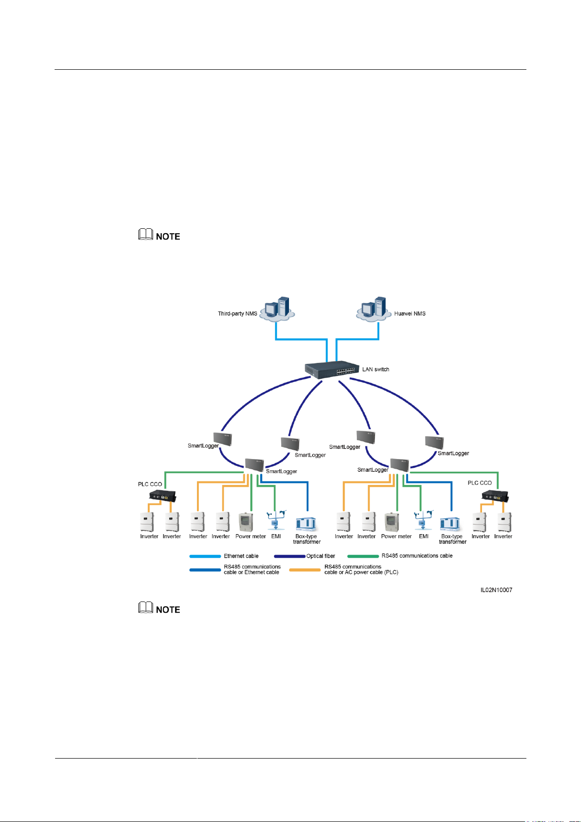
Fiber+RS485/PLC Networking
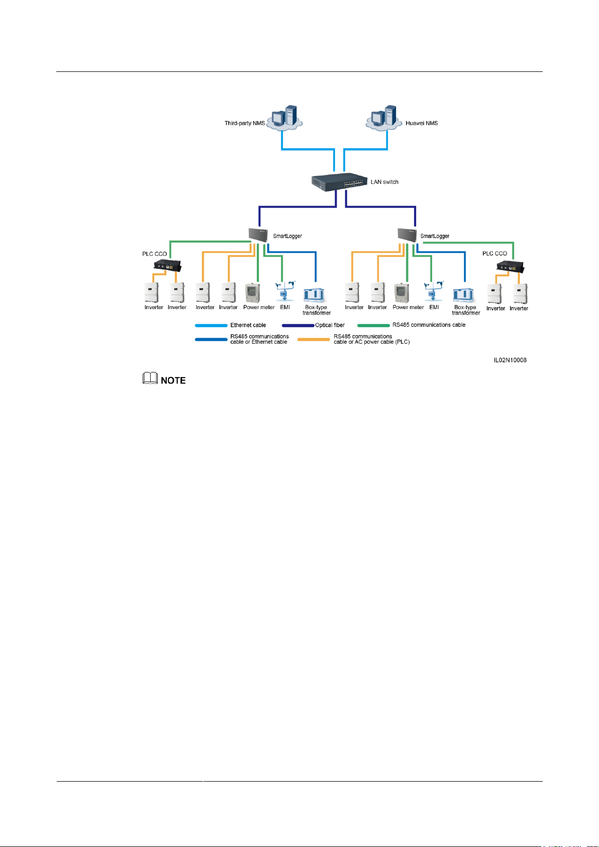
A fiber network is classified into a ring network and a star network, as shown in Figure 2-6
and Figure 2-7 respectively.
In the fiber networking, the SmartLogger connects to an inverter over an RS485
communications cable or an AC power cable, connects to a box-type transformer over an
RS485 communications cable or an Ethernet network cable, and connects to southbound
devices such as the EMI and power meter over RS485 communications cables.
The SmartLogger can work with the SUN2000 equipped with the PLC STA module over an embedded
or external PLC CCO module to implement PLC networking over power cables.
Figure 2-6 Fiber ring network diagram
The SmartLogger provides two 100M Ethernet optical ports to implement ring networking.
A maximum of 16 SmartLoggers can be connected to form a fiber ring network. Each SmartLogger
can connect to southbound devices such as the inverter, EMI, and power meter.
Multiple fiber ring networks can converge over an Ethernet switch or SmartLogger and then connect
to an NMS.
Page 21
SmartLogger2000-(10-C, 11-C)
User Manual
2 Product Overview
Issue Draft A (2017-02-15)
Huawei Proprietary and Confidential
Copyright © Huawei Technologies Co., Ltd.
13
Figure 2-7 Fiber star network diagram
Multiple SmartLoggers can converge over an Ethernet switch and then connect to an NMS.
The SmartLogger connects to the Ethernet switch over optical fibers with the maximum
communications distance of 12 km in between.
LTE+RS485/PLC Networking
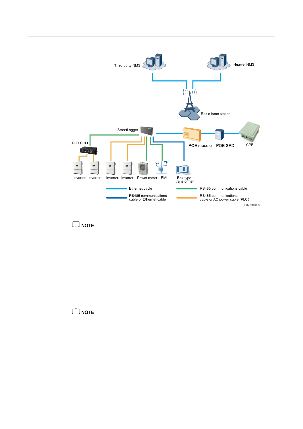
Figure 2-8 shows the LTE+RS485/PLC network diagram.
In the LTE wireless networking scenario, the SmartLogger connects to an inverter over an
RS485 communications cable or an AC power cable, connects to a box-type transformer over
an RS485 communications cable or an Ethernet network cable, connects to southbound
devices such as the EMI and power meter over RS485 communications cables, connects to a
customer premises equipment (CPE) over an Ethernet electrical port, and transmits
information collected from southbound devices to an NMS in wireless mode.
Page 22
SmartLogger2000-(10-C, 11-C)
User Manual
2 Product Overview
Issue Draft A (2017-02-15)
Huawei Proprietary and Confidential
Copyright © Huawei Technologies Co., Ltd.
14
Figure 2-8 LTE+RS485/PLC network diagram
The IP addresses for the SmartLogger, CPE, and monitoring device in the box-type transformer must
be in the same network segment.
The IP address planned for the SmartLogger needs to be imported to the third-party NMS for the
NMS to proactively connect to the SmartLogger.
The IP address planned for the box-type transformer needs to be imported to the third-party NMS for
the NMS to proactively connect to the box-type transformer.
2.5 System Wiring Diagram
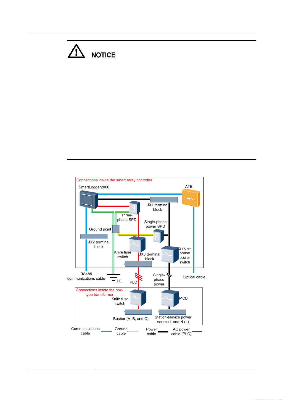
Scenario with a Smart Array Controller
Huawei smart array controller, also a communication box, is an outdoor cabinet that controls the
communication of the PV array in a PV plant. The cabinet can house the SmartLogger, ATB, POE
module, and POE SPD.
This document describes the application scenario where the SmartLogger is inside the smart array
controller SmartACU2000A-D-PLC.
Page 23
SmartLogger2000-(10-C, 11-C)
User Manual
2 Product Overview
Issue Draft A (2017-02-15)
Huawei Proprietary and Confidential
Copyright © Huawei Technologies Co., Ltd.
15
The general single-phase input power cable for the smart array controller needs to be
prepared by the customer. You are advised to use a two-core armor copper cable with an
operating voltage to the ground greater than or equal to 300 V and a cross-sectional area of
4 mm2 for each core wire.
The power cable from the miniature circuit breaker (MCB) to the station-service power
source needs to be prepared by the customer. You are advised to use a two-core armor
copper cable with an operating voltage to the ground greater than or equal to 300 V and a
cross-sectional area of 4 mm2 for each core wire.
The PLC three-phase input power cable for the smart array controller needs to be prepared
by the customer. You are advised to use a three-core armor copper cable with an operating
voltage greater than or equal to 1000 V and a cross-sectional area of 10 mm2 for each core
wire. Connect this cable only in the PLC networking scenario.
The cable from the busbar to the knife fuse switch needs to be prepared by the customer.
You are advised to use a three-core, multi-strand armor cable with an operating voltage to
the ground greater than or equal to 1000 V and a cross-sectional area of 10 mm2 for each
core wire. Connect this cable only in the PLC networking scenario.
Figure 2-9 Fiber+RS485/PLC
Page 24
SmartLogger2000-(10-C, 11-C)
User Manual
2 Product Overview
Issue Draft A (2017-02-15)
Huawei Proprietary and Confidential
Copyright © Huawei Technologies Co., Ltd.
16
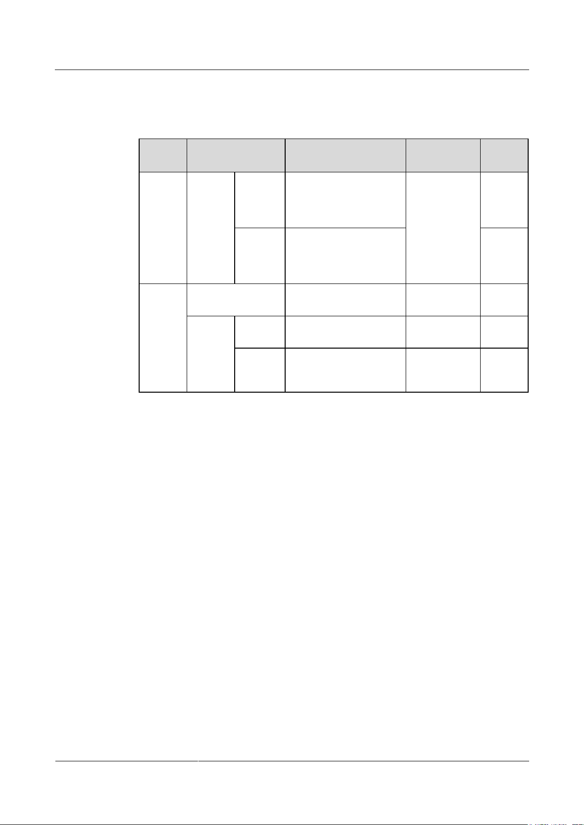
Table 2-4 lists the components required for the fiber+RS485/PLC networking mode in the
Locatio
n
Component
Recommended Model
or Specifications
Type
Quantit
y
Smart
array
controlle
r
Fitting
bag for
fiber
ring
switchin
g
Low-spe
ed
optical
module
FTLF1323P1BTR-HW
Can be
purchased
from Huawei
2
Optical
jumper
PLCLC5S-ST3P302-HW,
LC-LC-S2-L2,
3ECA1031LCLC002-01F, or LP-LP-2S-P-SM-002
8
Box-typ
e
transfor
mer
MCB
Rated current: 32 A;
number of poles: 2
Prepared by
the customer
1
Knife
switch
Fuse
Rated voltage ≥ 800 V;
rated current: 32 A
Prepared by
the customer
3
Knife
switch
box
Rated voltage ≥ 800 V;
rated current ≥ 32 A;
number of poles: 3
Prepared by
the customer
1
scenario with a smart array controller.
Table 2-4 Components required
Page 25
SmartLogger2000-(10-C, 11-C)
User Manual
2 Product Overview
Issue Draft A (2017-02-15)
Huawei Proprietary and Confidential
Copyright © Huawei Technologies Co., Ltd.
17
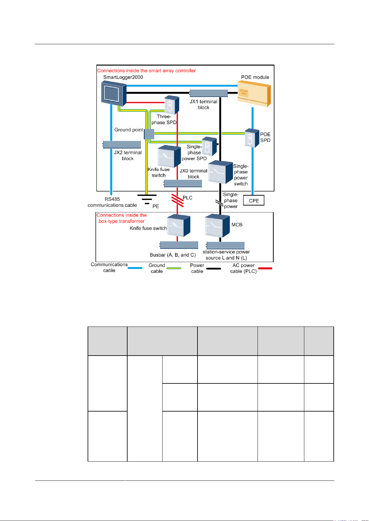
Figure 2-10 LTE+RS485/PLC
Location
Component
Recommended
Model or
Specifications
Type
Quanti
ty
Smart array
controller
POE and
CPE
fitting
bags
POE
module
N/A
Can be
purchased
from Huawei
1
POE SPD
N/A
Can be
purchased
from Huawei
1
Outside the
smart array
controller
and
box-type
transformer
CPE
N/A
Can be
purchased
from Huawei
1
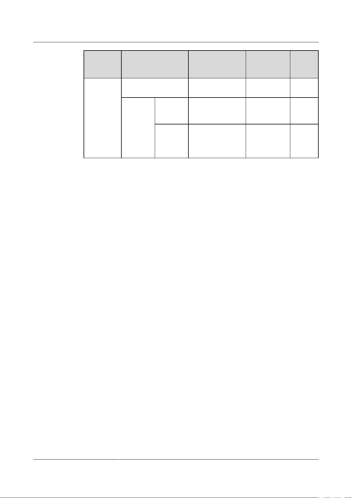
Table 2-5 lists the components required for the LTE+RS485/PLC networking mode in the
scenario with a smart array controller.
Table 2-5 Components required
Page 26
SmartLogger2000-(10-C, 11-C)
User Manual
2 Product Overview
Issue Draft A (2017-02-15)
Huawei Proprietary and Confidential
Copyright © Huawei Technologies Co., Ltd.
18
Location
Component
Recommended
Model or
Specifications
Type
Quanti
ty
Box-type
transformer
MCB
Rated current: 32 A;
number of poles: 2
Prepared by
the customer
1
Knife
switch
Fuse
Rated voltage ≥ 800
V; rated current: 32
A
Prepared by
the customer
3
Knife
switch box
Rated voltage ≥ 800
V; rated current ≥
32 A; number of
poles: 3
Prepared by
the customer
1
Scenario Without a Smart Array Controller
Page 27
SmartLogger2000-(10-C, 11-C)
User Manual
2 Product Overview
Issue Draft A (2017-02-15)
Huawei Proprietary and Confidential
Copyright © Huawei Technologies Co., Ltd.
19
Component
Recommended Model or
Specifications
Type
Quantity
SmartLogger
SmartLogger2000
Can be purchased
from Huawei
1
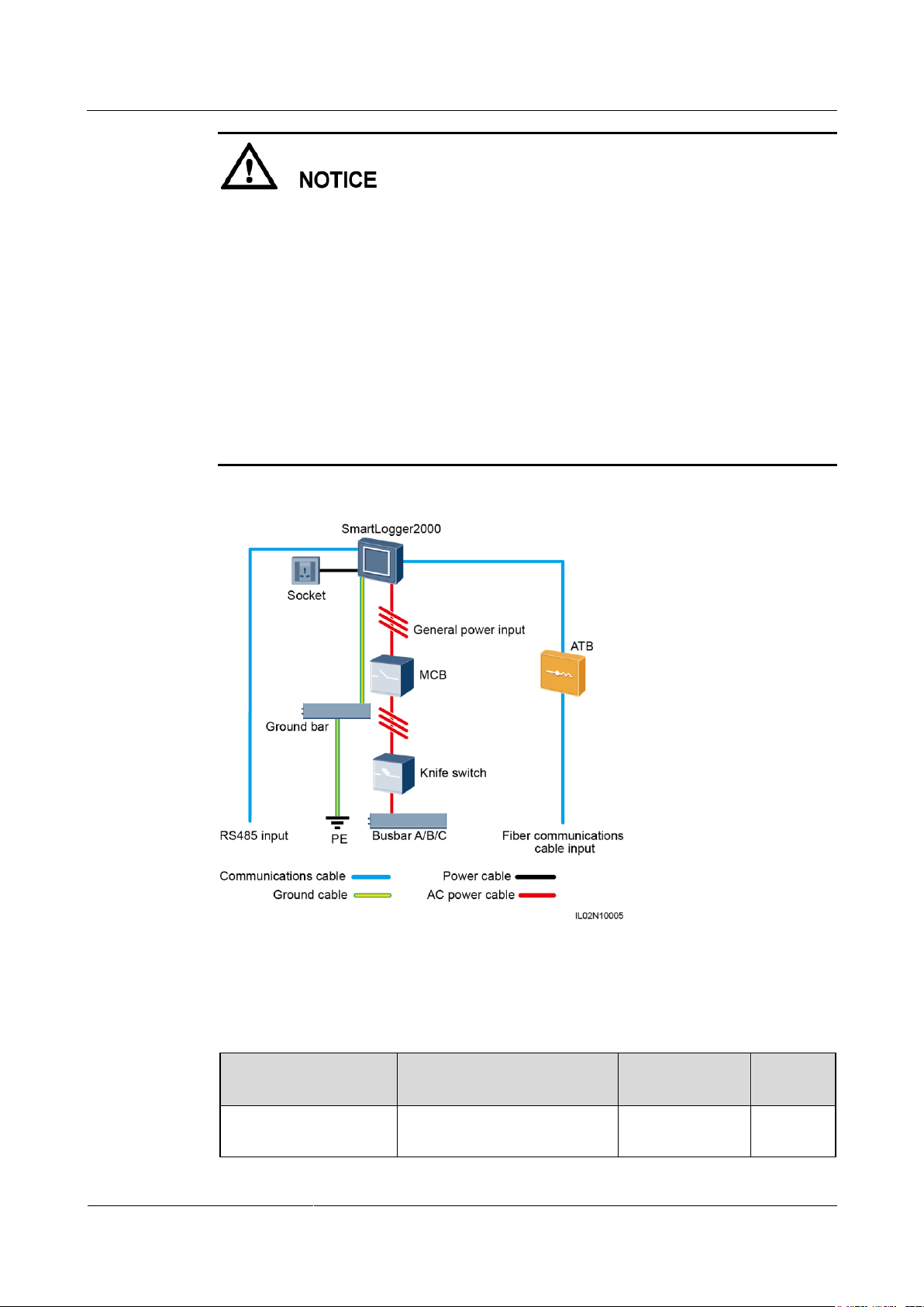
If the SmartLogger uses an AC power cable for communication, an MCB or a knife fuse
switch needs to be installed to prevent device damage in the case of short circuits.
If the SmartLogger communicates with the SUN2000 over an AC power cable, the cable
from the knife fuse switch to the MCB and the cable from the busbar to the knife fuse
switch both need to be prepared by yourself. You are advised to use a three-core armored
cable with the operating voltage to the ground greater than or equal to 1000 V and a
cross-sectional area of a single core wire being 10 mm2.
The SmartLogger can connect to the SUN2000 over an RS485 communications cable or
AC power cable. If RS485 is used, there is no need to connect an AC power cable between
the SmartLogger and the MCB in the scenario without a smart array controller.
The power cable delivered with the SmartLogger is 1 meter long, the power adapter cable
is 1.5 meters long, the network cable is 2.2 meters long, and the AC power cable is 1.5
meters long. Reserve the installation positions for components based on the cable lengths.
Figure 2-11 Fiber+RS485/PLC
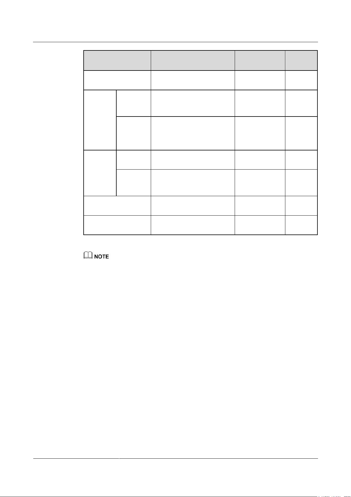
Table 2-6 lists the components required for the fiber+RS485/PLC networking mode in the
scenario without a smart array controller.
Table 2-6 Components required
Page 28
SmartLogger2000-(10-C, 11-C)
User Manual
2 Product Overview
Issue Draft A (2017-02-15)
Huawei Proprietary and Confidential
Copyright © Huawei Technologies Co., Ltd.
20
Component
Recommended Model or
Specifications
Type
Quantity
ATB
CT-GZF2PJ-8 or
CT-GPH-A-8
Can be purchased
from Huawei
1
Fitting
bag for
fiber ring
switching
Low-speed
optical
module
FTLF1323P1BTR-HW
Can be purchased
from Huawei
2
Optical
jumper
PLCLC5S-ST3P302-HW,
LC-LC-S2-L2,
3ECA1031LCLC002-01-F, or
LP-LP-2S-P-SM-002
Can be purchased
from Huawei
8
Knife
switch
Fuse
Rated voltage ≥ 800 V; rated
current: 32 A
Prepared by the
customer
3
Knife
switch box
Rated voltage ≥ 800 V; rated
current ≥ 32 A; number of
poles: 3
Prepared by the
customer
1
MCB
Rated voltage ≥ 800 V; rated
current ≥ 32 A
Prepared by the
customer
1
Socket
Matching with the power
adapter
Prepared by the
customer
1
Length of the cable used for connecting components depends on the survey result.
Page 29
SmartLogger2000-(10-C, 11-C)
User Manual
2 Product Overview
Issue Draft A (2017-02-15)
Huawei Proprietary and Confidential
Copyright © Huawei Technologies Co., Ltd.
21
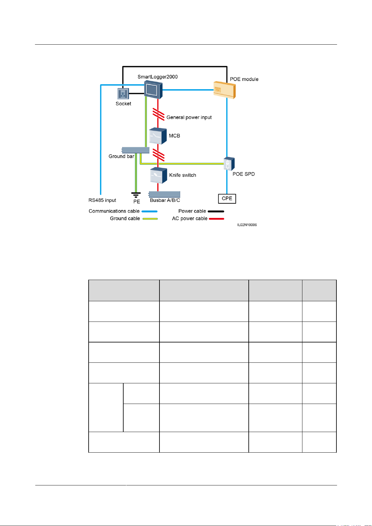
Figure 2-12 LTE+RS485/PLC
Component
Recommended Model or
Specifications
Type
Quantity
SmartLogger
SmartLogger2000
Can be purchased
from Huawei
1
POE module
POE35-54A or POE85-56A
Can be purchased
from Huawei
1
POE SPD
POE-2A
Can be purchased
from Huawei
1
CPE
EG860V2-C71
Can be purchased
from Huawei
1
Knife
switch
Fuse
Rated voltage ≥ 800 V; rated
current: 32 A
Prepared by the
customer
3
Knife
switch box
Rated voltage ≥ 800 V; rated
current ≥ 32 A; number of
poles: 3
Prepared by the
customer
1
MCB
Rated voltage ≥ 800 V; rated
current ≥ 32 A
Prepared by the
customer
1
Table 2-7 lists the components required for the LTE+RS485/PLC networking mode in the
scenario without a smart array controller.
Table 2-7 Components required
Page 30

SmartLogger2000-(10-C, 11-C)
User Manual
2 Product Overview
Issue Draft A (2017-02-15)
Huawei Proprietary and Confidential
Copyright © Huawei Technologies Co., Ltd.
22
Component
Recommended Model or
Specifications
Type
Quantity
Socket
Matching with the power
adapter
Prepared by the
customer
1
Length of the cable used for connecting components depends on the survey result.
Page 31

SmartLogger2000-(10-C, 11-C)
User Manual
3 Device Installation
Issue Draft A (2017-02-15)
Huawei Proprietary and Confidential
Copyright © Huawei Technologies Co., Ltd.
23
3.1 Precautions
Install the SmartLogger in an appropriate position and on a suitable surface.
3 Device Installation
Do not install the SmartLogger in areas with flammable or explosive materials.
Do not install the SmartLogger on flammable building materials.
3.2 Checking Before Installation
Checking the Outer Packing
Before unpacking the SmartLogger, check the outer packing for damage, such as holes and
cracks. If any damage is found, do not unpack the SmartLogger and contact the dealer
immediately.
Checking the Product and Accessories
After unpacking the SmartLogger, check that the product and accessories are intact and
complete, and free from any obvious damage. Contact the dealer if any damage is found or
any component is missing.
For details about the number of accessories delivered with the SmartLogger, see the Packing List in the
packing case.
Page 32
SmartLogger2000-(10-C, 11-C)
User Manual
3 Device Installation
Issue Draft A (2017-02-15)
Huawei Proprietary and Confidential
Copyright © Huawei Technologies Co., Ltd.
24
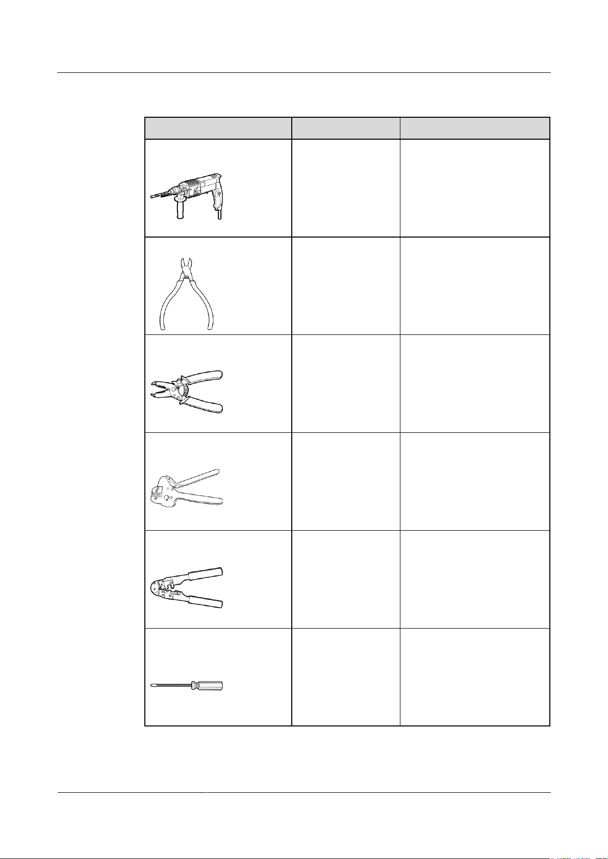
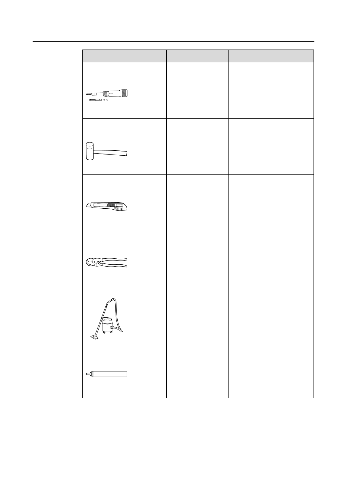
3.3 Tools
Tool
Model
Used To
Hammer drill
Drill bit (Ф6 mm)
Drill holes in the wall when the
SmartLogger is wall-mounted.
Diagonal pliers
-
Cut cable ties.
Wire stripper
-
Peel off cable jackets.
Crimping tool
H4TC0001
Manufacturer:
Amphenol
Crimp cables.
RJ45 crimping tool
-
Crimp RJ45 plug connectors for
communications cables.
Flat-head screwdriver
3x100
Tighten screws on the cable
terminal block.
Page 33
SmartLogger2000-(10-C, 11-C)
User Manual
3 Device Installation
Issue Draft A (2017-02-15)
Huawei Proprietary and Confidential
Copyright © Huawei Technologies Co., Ltd.
25
Tool
Model
Used To
Torque screwdriver
Phillips head: M4 and
ST3.5
Tighten screws during device
installation.
Rubber mallet
-
Hammer expansion sleeves into
holes.
Utility knife
-
Remove packing.
Wire clippers
-
Cut cables.
Vacuum cleaner
-
Clean up dust after holes are
drilled.
Marker
Diameter: ≤ 10 mm
Mark signs.
Page 34
SmartLogger2000-(10-C, 11-C)
User Manual
3 Device Installation
Issue Draft A (2017-02-15)
Huawei Proprietary and Confidential
Copyright © Huawei Technologies Co., Ltd.
26
Tool
Model
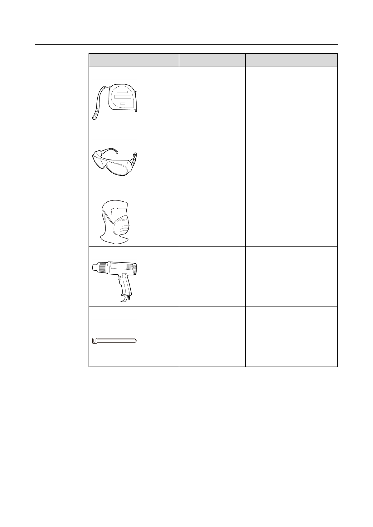
Used To
Measuring tape
-
Measure distances.
Safety goggles
-
Protect the operator's eyes from
dust during hole drilling.
Anti-dust respirator
-
Protect an operator from dust
inhalation during hole drilling.
Heat gun
-
Heat-shrink a tube.
Cable tie
-
Bind cables.
3.4 Determining the Installation Position
Comply with the following requirements when determining the installation position for the
SmartLogger:
The SmartLogger has a protection level of IP20. It cannot be installed outdoors.
The SmartLogger should be installed in a dry environment to protect it from water.
The ambient temperature should be within the range of –40°C to +60°C. Avoid exposing
the SmartLogger to direct sunlight.
Page 35
SmartLogger2000-(10-C, 11-C)
User Manual
3 Device Installation
Issue Draft A (2017-02-15)
Huawei Proprietary and Confidential
Copyright © Huawei Technologies Co., Ltd.
27
The communications distance must not exceed 1000 m for the RS485 port, and must not
exceed 100 m for the Ethernet port.
The SmartLogger should be installed at a proper height to facilitate operation and
maintenance.
Do not place the SmartLogger upside down; otherwise, dust will fall into ports at the
bottom of the SmartLogger, thereby reducing the service life.
The installation mode and position must be suitable for the SmartLogger weight (2.39 kg)
and dimensions with mounting ears (H x W x D: 411 mm x 170 mm x 58.6 mm).
If the SmartLogger is installed on a wall or along a guide rail, the area for connecting
cables should face downwards.
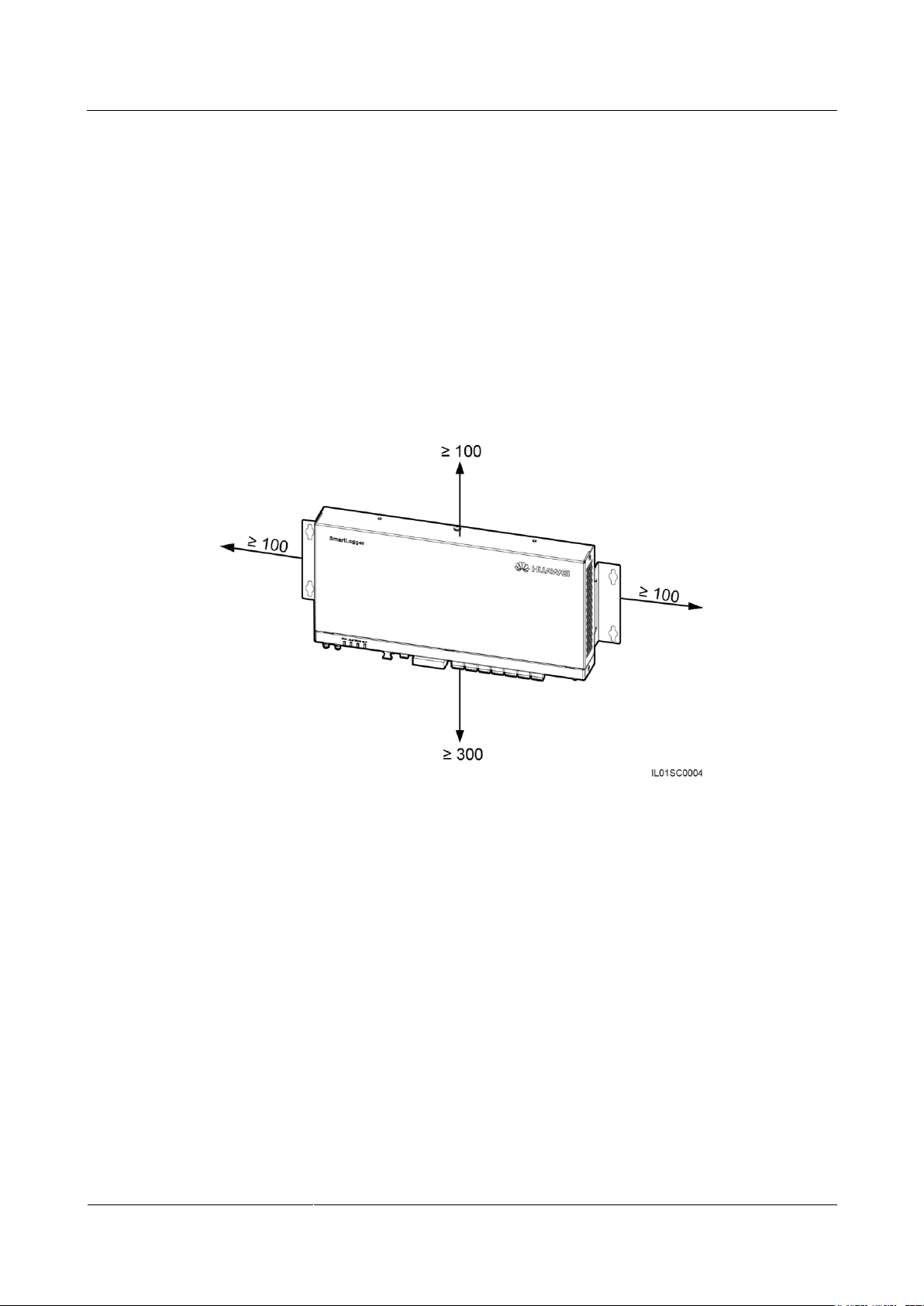
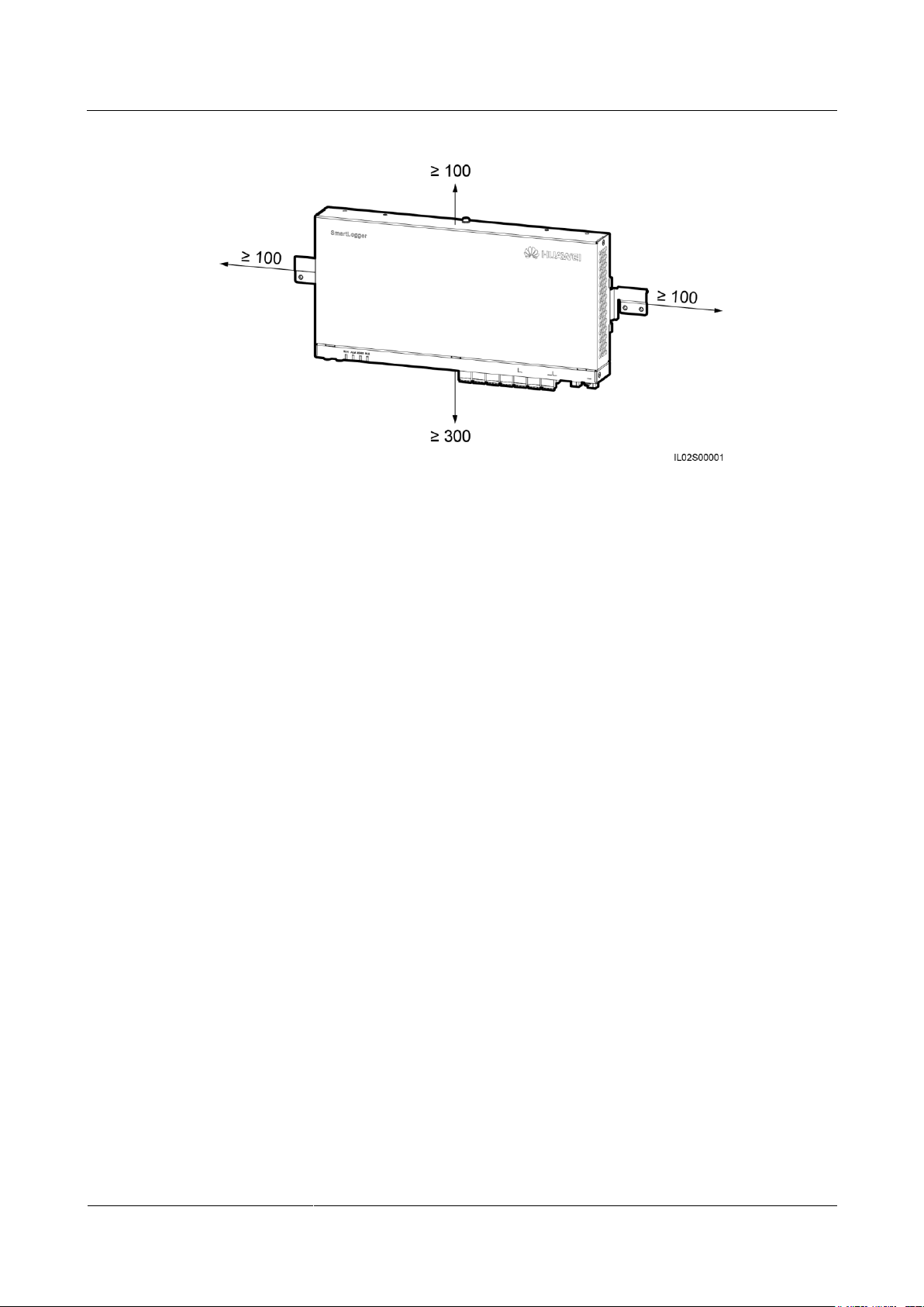
Figure 3-1 and Figure 3-2 show the minimum distance between the SmartLogger and
surrounding objects.
Figure 3-1 Minimum distance for wall mounting (unit: mm)
Page 36
SmartLogger2000-(10-C, 11-C)
User Manual
3 Device Installation
Issue Draft A (2017-02-15)
Huawei Proprietary and Confidential
Copyright © Huawei Technologies Co., Ltd.
28
Figure 3-2 Minimum distance for guide rail mounting (unit: mm)
3.5 Installing a SmartLogger
Context
In a scenario with a smart array controller, the SmartLogger is installed before delivery. In a
scenario without a smart array controller, the SmartLogger can be installed on a wall or along
a guide rail.
3.5.1 Installing a SmartLogger on a Wall
Context
Page 37
SmartLogger2000-(10-C, 11-C)
User Manual
3 Device Installation
Issue Draft A (2017-02-15)
Huawei Proprietary and Confidential
Copyright © Huawei Technologies Co., Ltd.
29
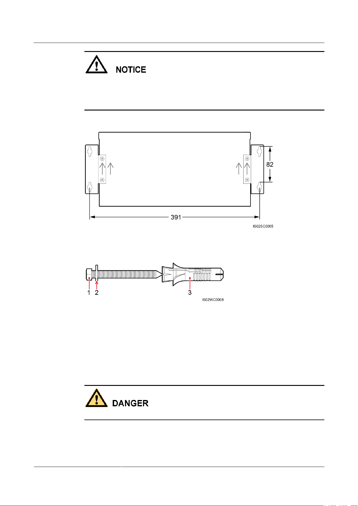
(1) ST3.5 tapping screw
(2) Washer
(3) Expansion sleeve
Choose a solid and smooth wall to ensure that the SmartLogger can be installed securely
on the wall.
Before hanging the SmartLogger on the screws, secure the expansion sleeves, washers,
and tapping screws into the wall.
Figure 3-3 Distance between the screw holes in the mounting ears for the SmartLogger (unit: mm)
Procedure
Step 1 Determine mounting holes based on the hole positions in the mounting ears, and mark the
Figure 3-4 Screw assembly for wall-mounted installation
mounting holes using a marker.
Avoid drilling holes in the water pipes and power cables buried in the wall.
Page 38
SmartLogger2000-(10-C, 11-C)
User Manual
3 Device Installation
Issue Draft A (2017-02-15)
Huawei Proprietary and Confidential
Copyright © Huawei Technologies Co., Ltd.
30
If you need to use a ladder to install the SmartLogger on a high position, keep balance to
protect yourself from falling down.
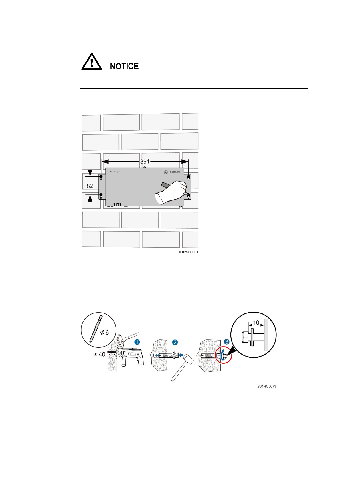
Figure 3-5 Hole positions and distance (unit: mm)
Step 2 Drill holes by using a hammer drill and install expansion sleeves, washers, and tapping
screws.
Figure 3-6 Drilling holes and installing expansion sleeves, washers, and tapping screws (unit:
mm)
1. Put a hammer drill with a Ф6 mm drill bit on a marked hole position vertically against
the wall and drill to a depth greater than or equal to 40 mm.
Page 39
SmartLogger2000-(10-C, 11-C)
User Manual
3 Device Installation
Issue Draft A (2017-02-15)
Huawei Proprietary and Confidential
Copyright © Huawei Technologies Co., Ltd.
31
To prevent dust inhalation or contact with eyes, the operator should wear an anti-dust
respirator and safety goggles when drilling holes.
Clean up any dust in and around the holes using a vacuum cleaner and measure the hole
distance. If the holes are inaccurately positioned, drill holes again.
2. Slightly tighten the expansion sleeves, vertically insert them into holes, and knock them
completely into the holes by using a rubber mallet.
3. Drive the tapping screws into the expansion sleeves, and reserve 10 mm outside of the
holes.
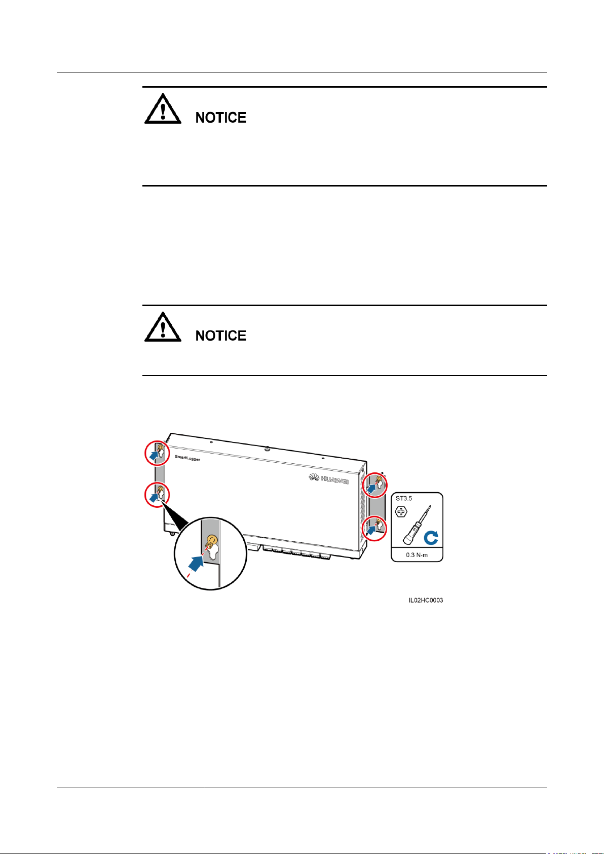
Step 3 Put the tapping screws through the SmartLogger mounting ears and washers into the
mounting holes in the wall.
When the SmartLogger is wall-mounted, ensure that the cable connection area faces
downwards for ease of cable connection and maintenance.
Step 4 Tighten the tapping screws using a torque screwdriver.
Figure 3-7 Tightening the tapping screws
----End
3.5.2 Installing a SmartLogger Along a Guide Rail
Context
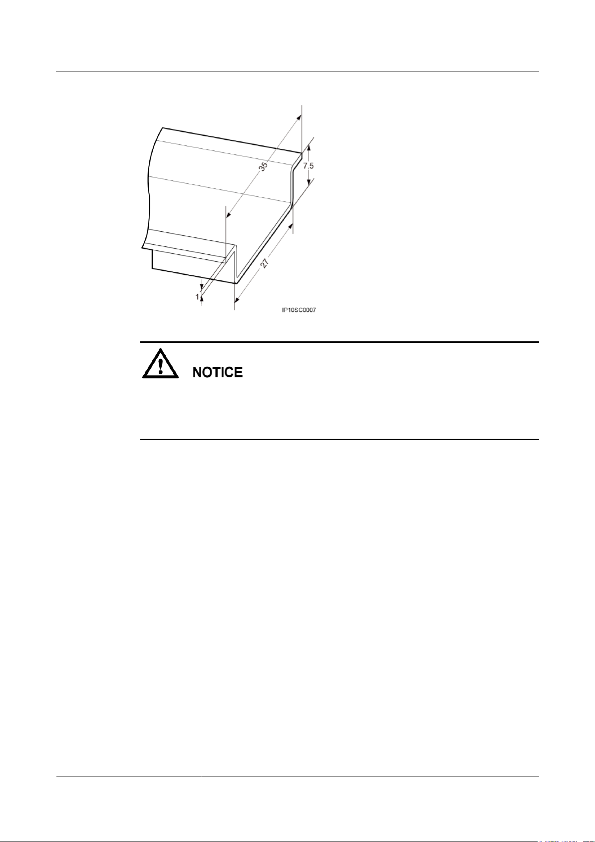
Huawei does not provide the SmartLogger guide rail. If you choose this installation mode,
prepare a 35 mm standard guide rail by yourself.
Page 40
SmartLogger2000-(10-C, 11-C)
User Manual
3 Device Installation
Issue Draft A (2017-02-15)
Huawei Proprietary and Confidential
Copyright © Huawei Technologies Co., Ltd.
32
Figure 3-8 Guide rail dimensions (unit: mm)
Procedure
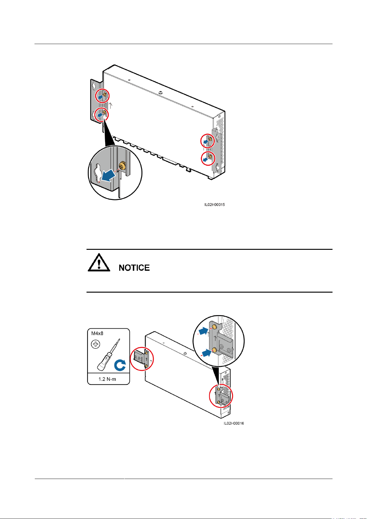
Step 1 Remove the mounting ears from the SmartLogger using a Phillips screwdriver.
Verify that the length of the guide rail is sufficient for securing the SmartLogger. The
recommended length is 450 mm or greater. If an RS485 signal SPD needs to be installed
on the guide rail, the recommended guide rail length is 600 mm or greater.
Ensure that the guide rail is secured before installing the SmartLogger.
Page 41
SmartLogger2000-(10-C, 11-C)
User Manual
3 Device Installation
Issue Draft A (2017-02-15)
Huawei Proprietary and Confidential
Copyright © Huawei Technologies Co., Ltd.
33
Figure 3-9 Removing mounting ears
Step 2 Secure the guide rail clamps using the screws that are removed from the mounting ears.
Install the guide rail clamps exactly as shown in the figure; otherwise, you may not be able to
mount the SmartLogger onto the guide rail.
Figure 3-10 Installing the guide rail clamps
Step 3 Mount the SmartLogger onto the guide rail.
Page 42
SmartLogger2000-(10-C, 11-C)
User Manual
3 Device Installation
Issue Draft A (2017-02-15)
Huawei Proprietary and Confidential
Copyright © Huawei Technologies Co., Ltd.
34
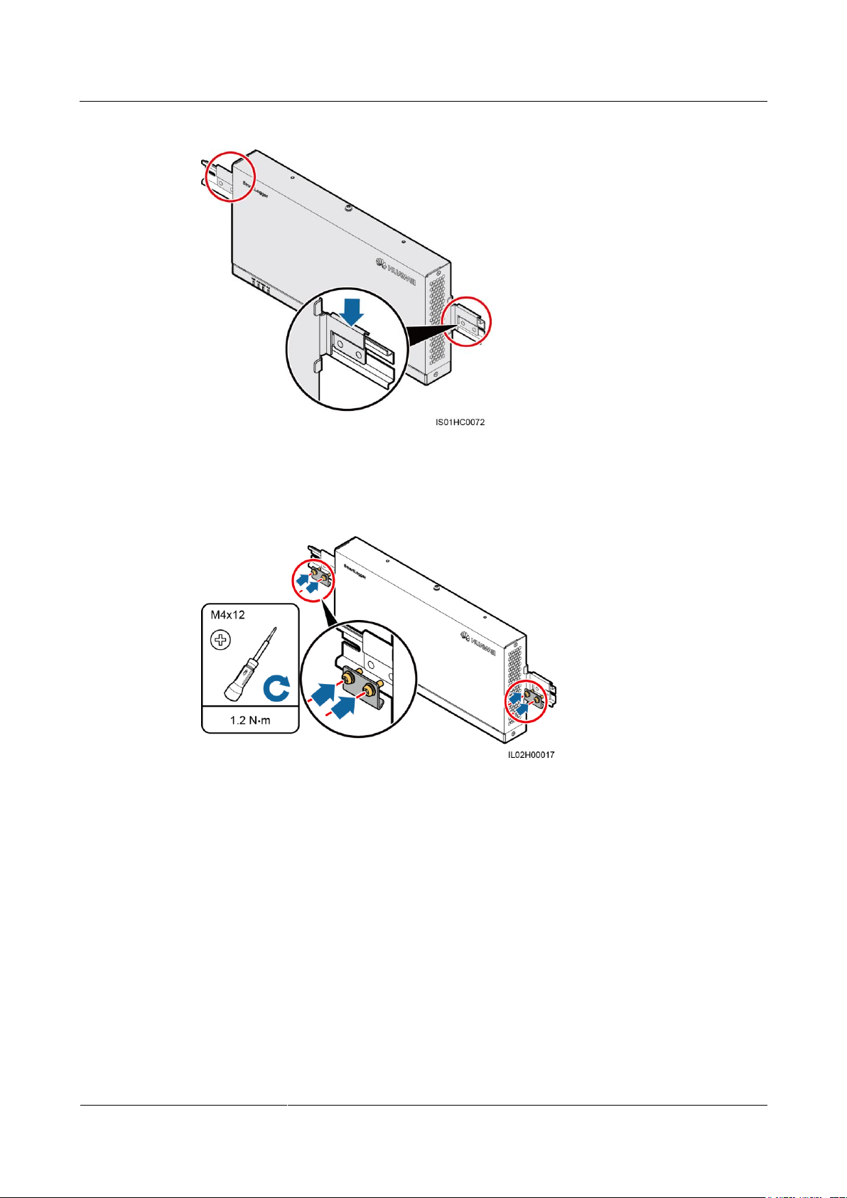
Figure 3-11 Mounting the SmartLogger onto the guide rail
Step 4 Install guide rail fasteners.
Figure 3-12 Installing guide rail fasteners
----End
Page 43

SmartLogger2000-(10-C, 11-C)
User Manual
4 Electrical Connection
Issue Draft A (2017-02-15)
Huawei Proprietary and Confidential
Copyright © Huawei Technologies Co., Ltd.
35
4.1 Precautions
This section describes how to connect the SmartLogger to inverters and other devices in the scenario
without a smart array controller.
In a scenario with a smart array controller, the SmartLogger is installed before delivery. Devices can
connect to the SmartLogger over RS485 communications cables or AC power cables. For detailed
operations, see the user manual for the appropriate smart array controller.
4 Electrical Connection
Ensure that all cables are connected securely.
The SmartLogger has no start key. Before the electrical connections for the SmartLogger
are complete, do not connect a power adapter to it.
4.2 Preparing an OT Terminal
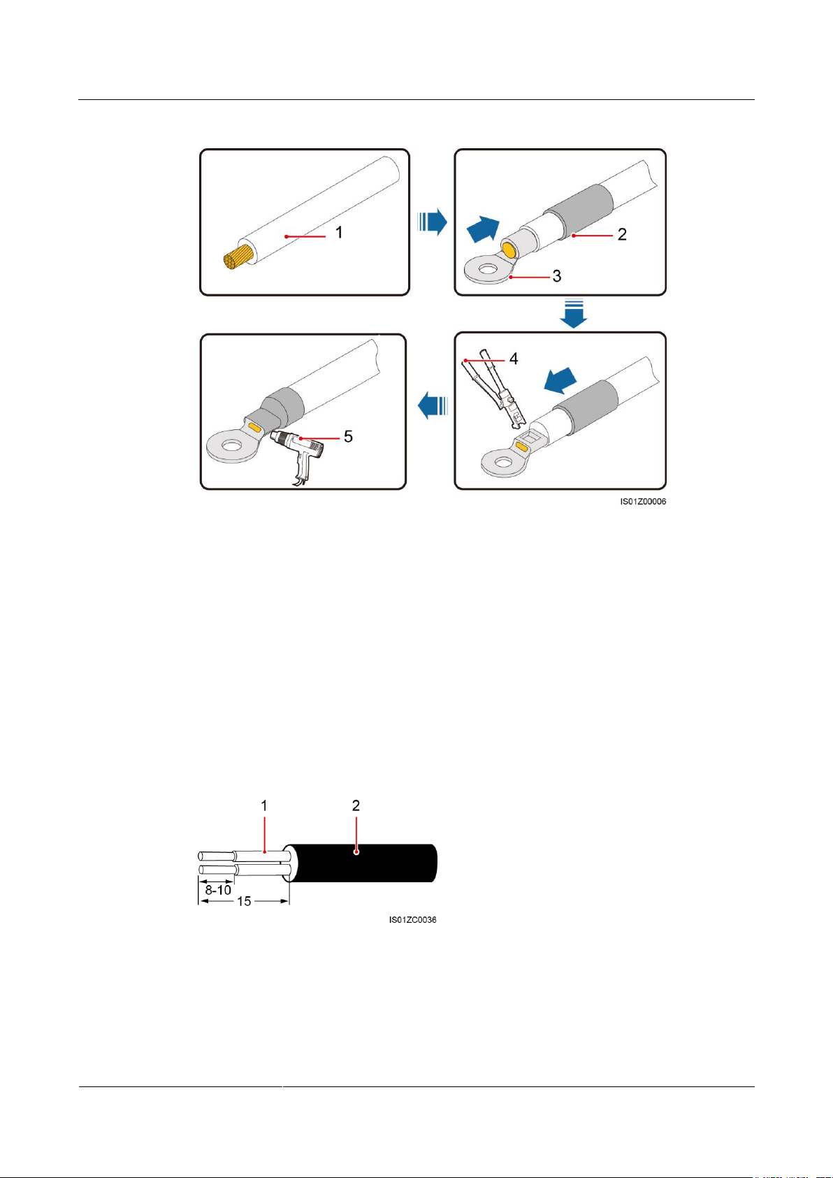
Figure 4-1 shows how to prepare an OT terminal.
Page 44
SmartLogger2000-(10-C, 11-C)
User Manual
4 Electrical Connection
Issue Draft A (2017-02-15)
Huawei Proprietary and Confidential
Copyright © Huawei Technologies Co., Ltd.
36
Figure 4-1 Preparing an OT terminal
(1) Cable
(2) Heat shrink tubing
(3) OT terminal
(4) Hydraulic pliers
(5) Heat gun
(1) Insulation layer
(2) Armored layer
4.3 Connecting Cables to the Terminal Block on the COM Port
Procedure
Step 1 Strip cables.
Figure 4-2 Stripping a cable (unit: mm)
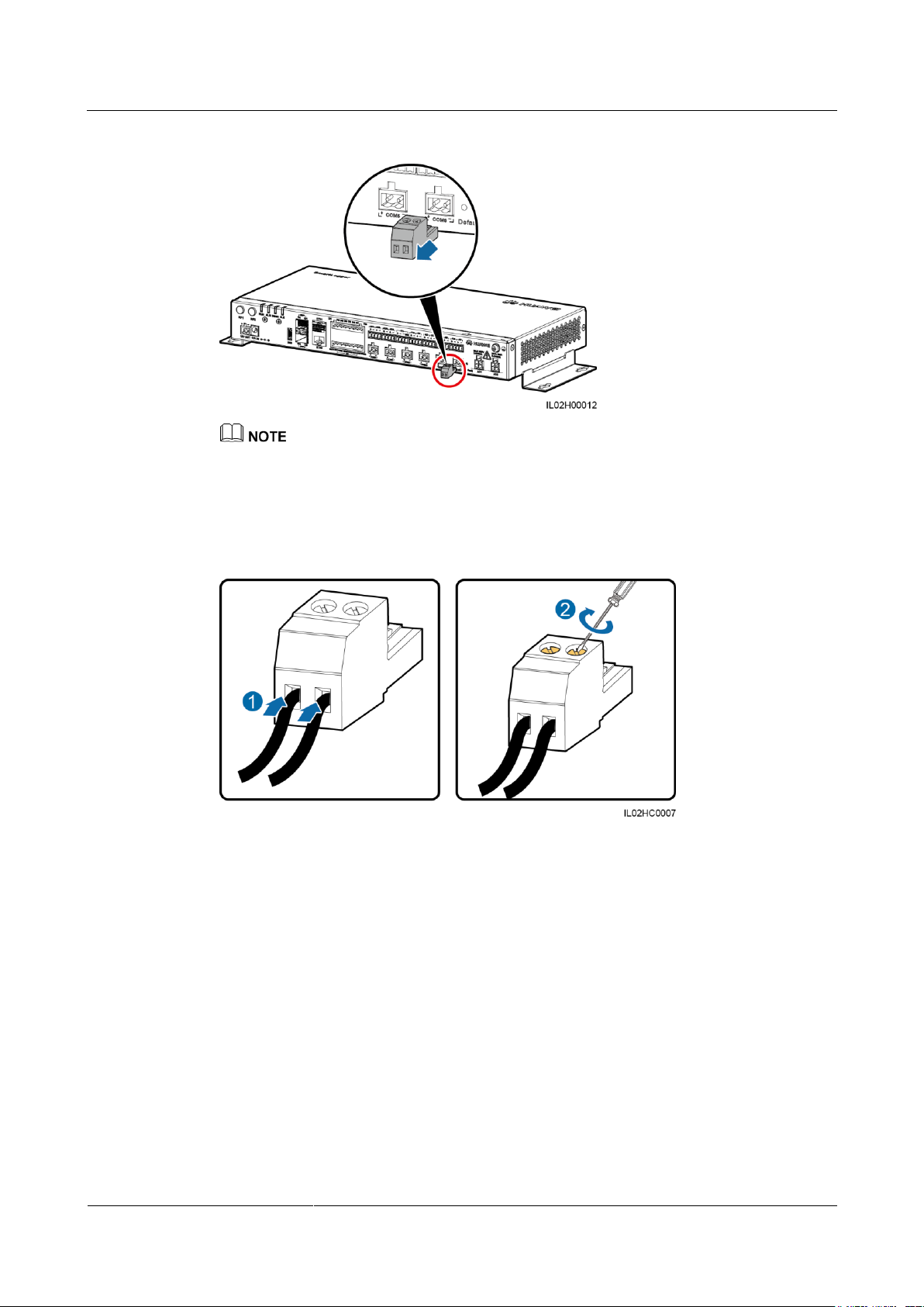
Step 2 Remove the terminal block from the COM port.
Page 45
SmartLogger2000-(10-C, 11-C)
User Manual
4 Electrical Connection
Issue Draft A (2017-02-15)
Huawei Proprietary and Confidential
Copyright © Huawei Technologies Co., Ltd.
37
Figure 4-3 Removing the terminal block
Use a flat-head screwdriver to remove the terminal block.
Step 3 Connect cables to the terminal block and secure the cables.
Figure 4-4 Connecting cables
Step 4 Insert the terminal block into the COM port.
----End
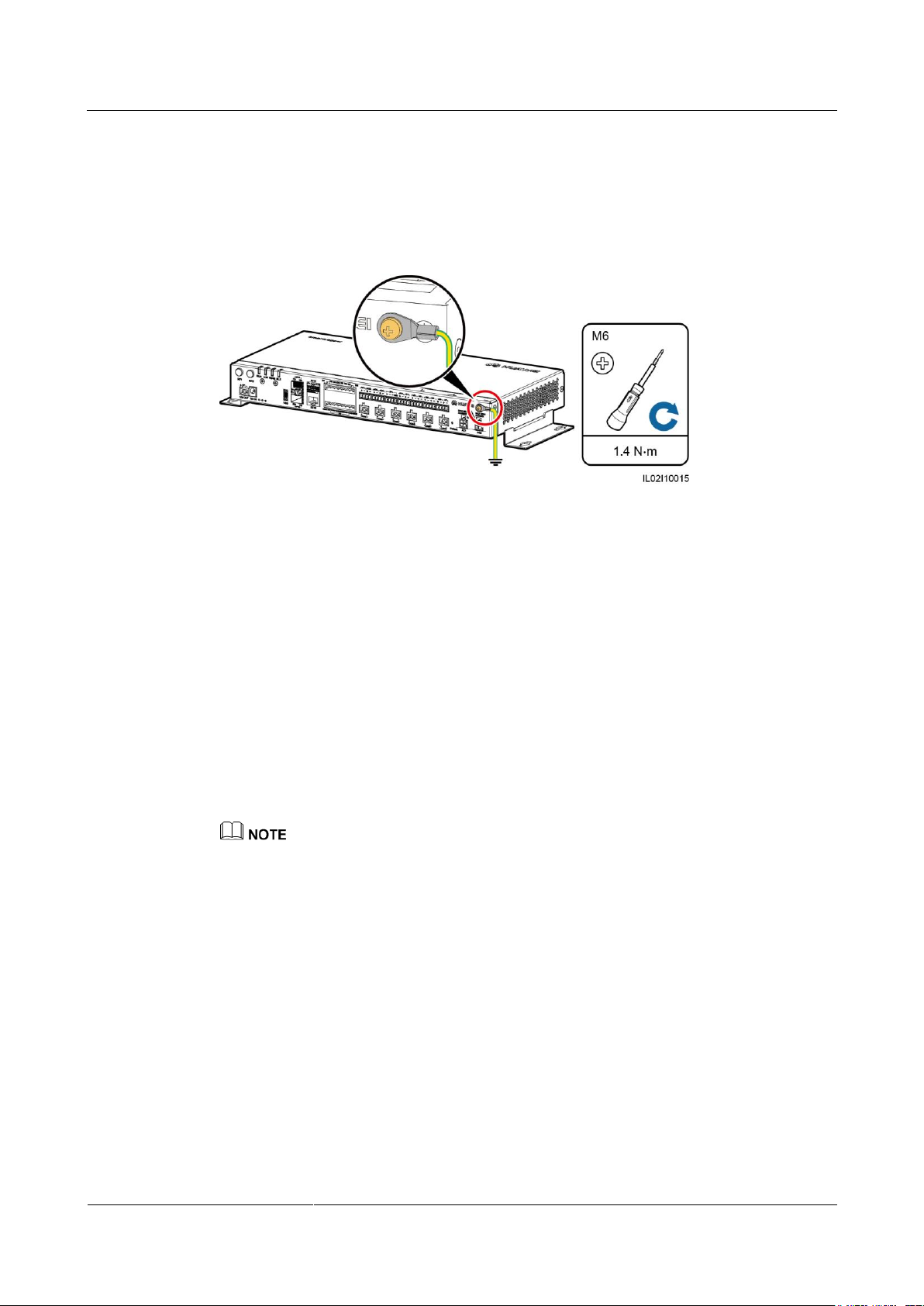
4.4 Connecting a PE Cable to the SmartLogger
Prerequisites
The PE cable and OT terminal are available.
Recommended PE cable: an outdoor copper-core cable with a cross sectional area of 4–6
mm2 or 12–10 AWG
OT terminal: M6
Page 46
SmartLogger2000-(10-C, 11-C)
User Manual
4 Electrical Connection
Issue Draft A (2017-02-15)
Huawei Proprietary and Confidential
Copyright © Huawei Technologies Co., Ltd.
38
Procedure
Step 1 Prepare an OT terminal by following the instructions in 4.2 Preparing an OT Terminal.
Step 2 Secure the PE cable using the ground screw.
Figure 4-5 Connecting the PE cable
----End
4.5 Connecting the SUN2000
4.5.1 Connection Description
The SmartLogger can be connected to the SUN2000 through an RS485 communications cable
or AC power cable. Communication modes for the SUN2000 with PLC and those without
PLC are different. Select an appropriate communication mode based on the actual situation.
For models with the PLC function, you can select either the PLC or RS485 communications
mode. For models without the PLC function, you can select only the RS485 communications
mode.
The RS485 and PLC communication modes are mutually exclusive.
If the RS485 communications mode is selected, do not connect an AC power cable to the PLC power
input port of the SmartLogger.
If PLC is used, do not connect an RS485 communications cable.
4.5.2 Connecting the SUN2000 Over RS485
Context
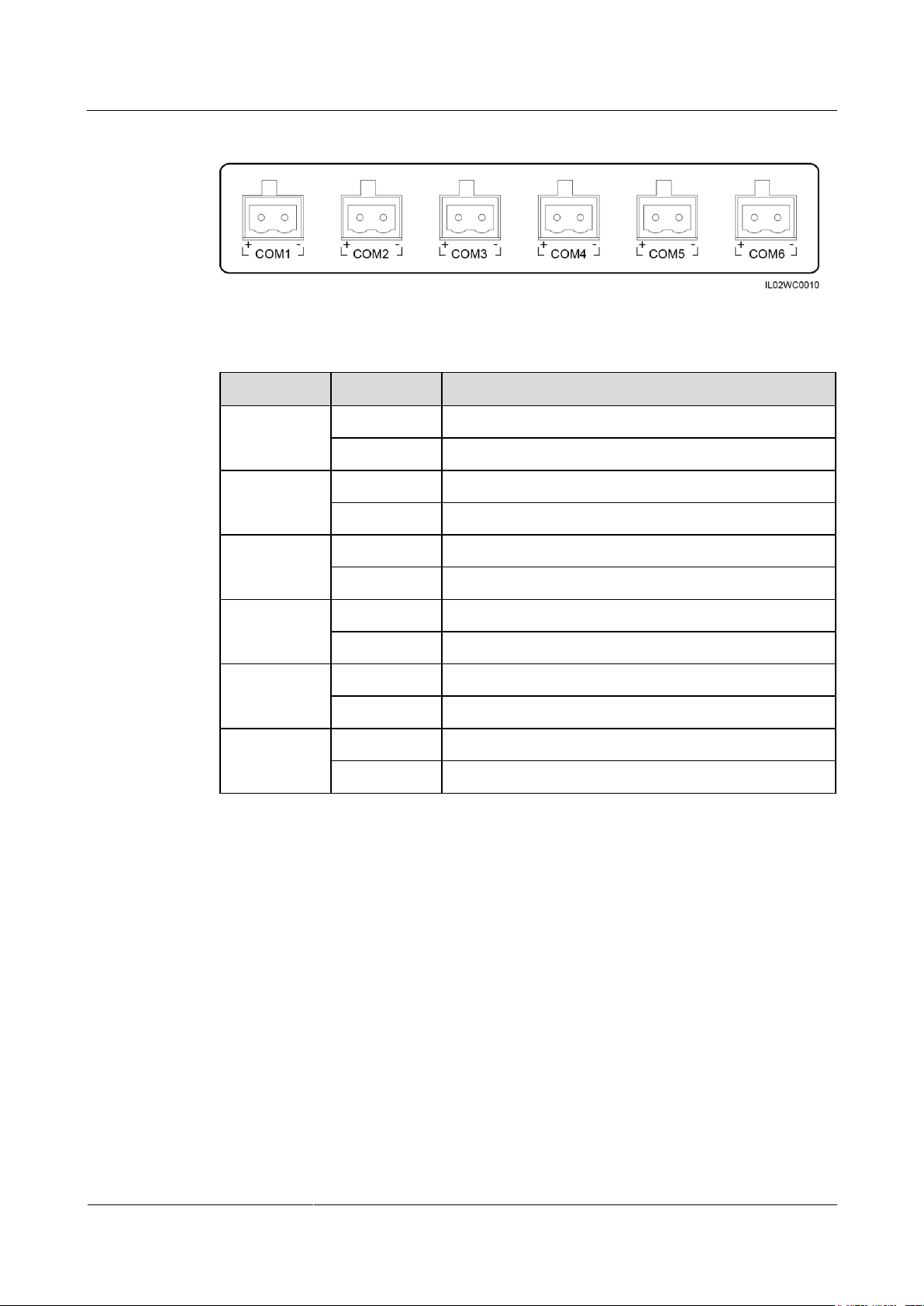
The SmartLogger provides six COM ports for RS485 communication, as shown in Figure 4-6.
Page 47
SmartLogger2000-(10-C, 11-C)
User Manual
4 Electrical Connection
Issue Draft A (2017-02-15)
Huawei Proprietary and Confidential
Copyright © Huawei Technologies Co., Ltd.
39
Figure 4-6 COM ports of the SmartLogger
Port
Identifier
Function
COM1
+
RS485A, RS485 differential signal+
-
RS485B, RS485 differential signal–
COM2
+
RS485A, RS485 differential signal+
-
RS485B, RS485 differential signal–
COM3
+
RS485A, RS485 differential signal+
-
RS485B, RS485 differential signal–
COM4
+
RS485A, RS485 differential signal+
-
RS485B, RS485 differential signal–
COM5
+
RS485A, RS485 differential signal+
-
RS485B, RS485 differential signal–
COM6
+
RS485A, RS485 differential signal+
-
RS485B, RS485 differential signal–
Table 4-1 COM port description
The RS485 terminal block or RJ45 port on the SUN2000 is used for RS485 communication.
There are two types of RS485 terminal blocks located in different models of SUN2000s.
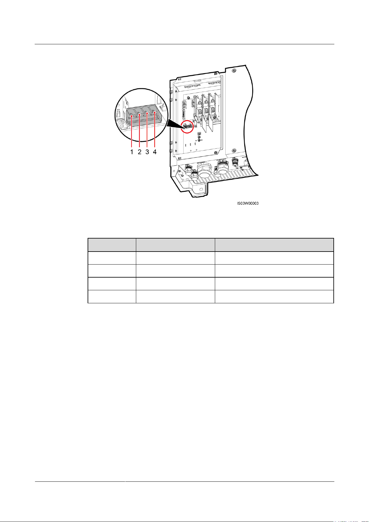
Terminal block connection
− Terminal block 1
Figure 4-7 shows the position of the terminal block in the SUN2000-50KTL. Table
4-2 describes the functions of the terminal block.
Page 48
SmartLogger2000-(10-C, 11-C)
User Manual
4 Electrical Connection
Issue Draft A (2017-02-15)
Huawei Proprietary and Confidential
Copyright © Huawei Technologies Co., Ltd.
40
No.
Port Definition
Function
1
RS485A IN
RS485A, RS485 differential signal+
2
RS485A OUT
RS485A, RS485 differential signal+
3
RS485B IN
RS485B, RS485 differential signal–
4
RS485B OUT
RS485B, RS485 differential signal–
Figure 4-7 Position of the terminal block in the SUN2000-50KTL
Table 4-2 Functions of the RS485 terminal block
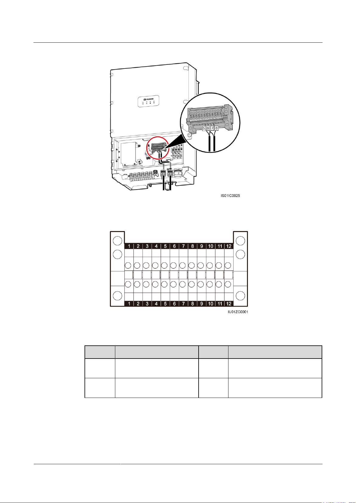
− Terminal block 2
Figure 4-8 shows the position of the terminal block in the SUN2000-33KTL/40KTL.
Table 4-3 describes the functions of the terminal block.
Page 49
SmartLogger2000-(10-C, 11-C)
User Manual
4 Electrical Connection
Issue Draft A (2017-02-15)
Huawei Proprietary and Confidential
Copyright © Huawei Technologies Co., Ltd.
41
No.
Function
No.
Function
5
RS485A (IN), RS485
differential signal+
6
RS485A (OUT), RS485
differential signal+
7
RS485B (IN), RS485
differential signal–
8
RS485B (OUT), RS485
differential signal–
Figure 4-8 Position of the terminal block in the SUN2000-33KTL/40KTL
Figure 4-9 Terminal block
Table 4-3 Functions of the RS485 terminal block
RJ45 port connection
The RJ45 port needs to be connected using an RJ45 connector, as shown in Figure 4-10.
Page 50
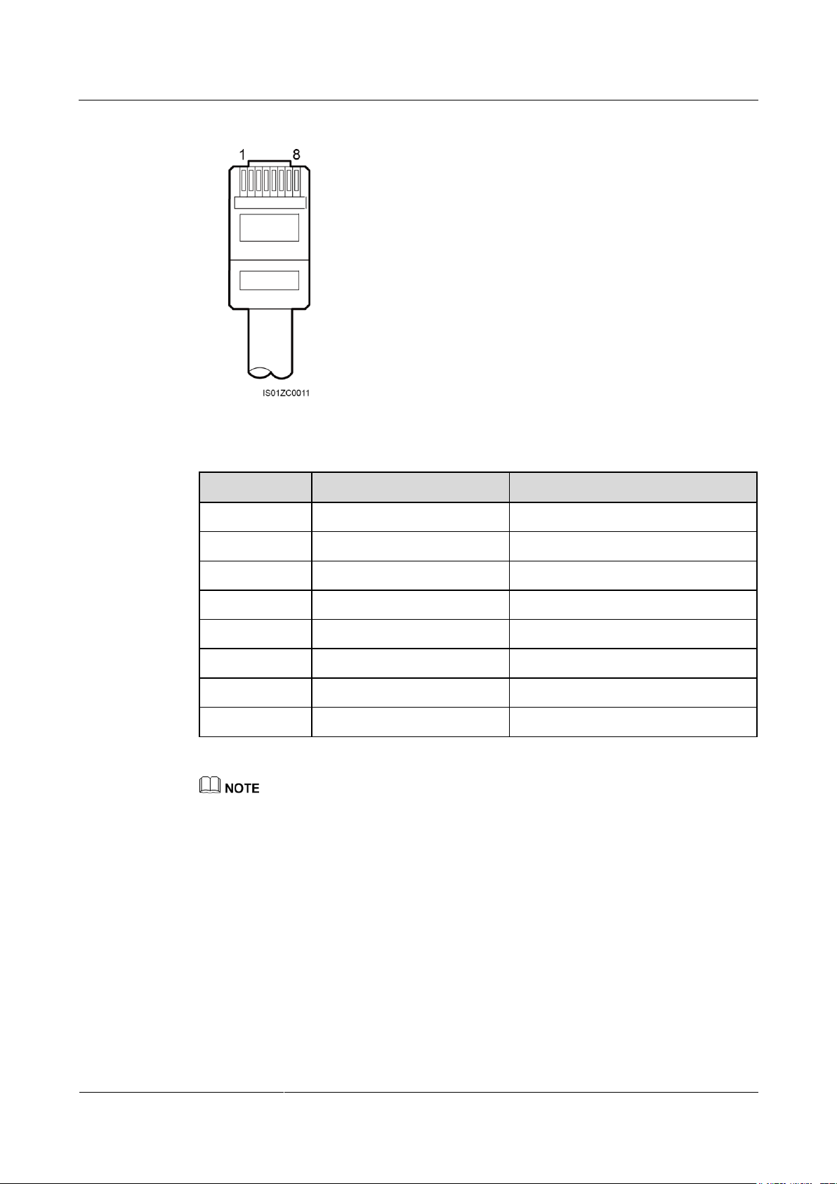
SmartLogger2000-(10-C, 11-C)
User Manual
4 Electrical Connection
Issue Draft A (2017-02-15)
Huawei Proprietary and Confidential
Copyright © Huawei Technologies Co., Ltd.
42
Figure 4-10 RS485 RJ45 connector of the SUN2000 (side view without the fastener)
No.
Color
Function
1
White-and-orange
RS485A, RS485 differential signal+
2
Orange
RS485B, RS485 differential signal–
3
White-and-green
N/A
4
Blue
RS485A, RS485 differential signal+
5
White-and-blue
RS485B, RS485 differential signal–
6
Green
N/A
7
White-and-brown
N/A
8
Brown
N/A
Table 4-4 Shielded network cable description
This section describes how to connect the SUN2000-50KTL to the SmartLogger through a terminal
block.
Figure 4-11 shows the connection between the SmartLogger and the SUN2000 over an RS485
communications cable.
Page 51
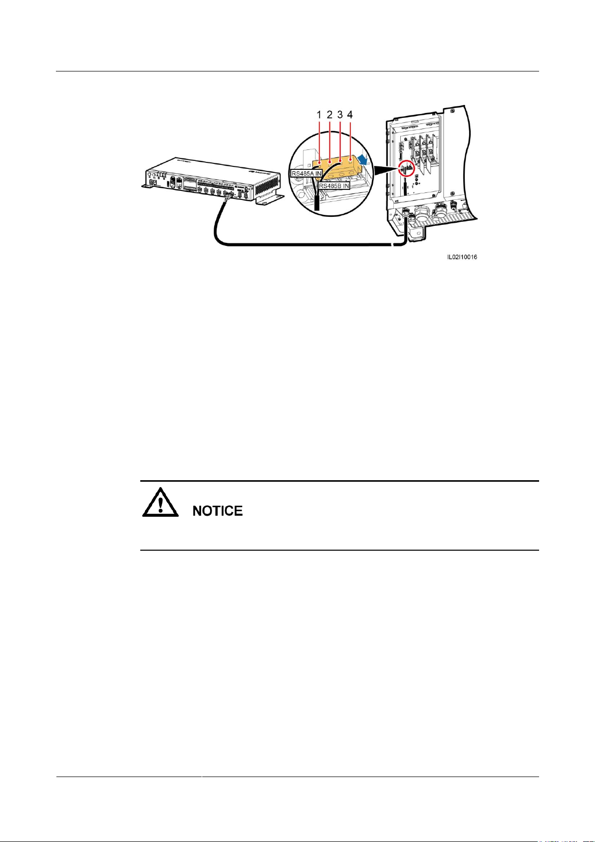
SmartLogger2000-(10-C, 11-C)
User Manual
4 Electrical Connection
Issue Draft A (2017-02-15)
Huawei Proprietary and Confidential
Copyright © Huawei Technologies Co., Ltd.
43
(1) RS485A IN
(2) RS485A OUT
(3) RS485B IN
(4) RS485B OUT
Procedure
Step 1 Prepare a cable with an appropriate length, strip a proper part of the insulation layer from one
Figure 4-11 Connecting the SmartLogger to the SUN2000
end, and connect the end to the SUN2000 terminal block.
You are advised to use a DJYP2VP2-22 2x2x1 PC cable or a communications cable with
a conductor cross-sectional area of 1 mm2 and a cable outer diameter of 14–18 mm.
For details about how to strip and connect the cable, see the SUN2000 user manual.
Step 2 Connect the other end of the cable to the COM port of the SmartLogger. For details, see 4.3
Connecting Cables to the Terminal Block on the COM Port.
When connecting the cable, ensure that the RS485A (IN) port and RS485B (IN) port on the
SUN2000 respectively connect to the COM+ port and COM– port on the SmartLogger.
Step 3 The Baud Rate settings for the SUN2000 and SmartLogger must be the same.
For details about the communications parameter settings for the SmartLogger, see 7.9.2.2
Setting RS485 Parameters or the SUN2000 App User Manual.
For details about the communications parameter settings for the SUN2000, see the
SUN2000 APP User Manual.
----End
Follow-up Procedure
Disconnection can be performed in reverse order.
Page 52
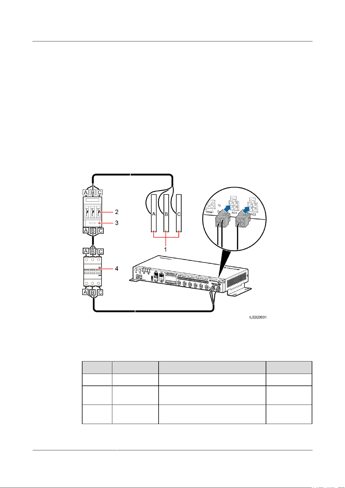
SmartLogger2000-(10-C, 11-C)
User Manual
4 Electrical Connection
Issue Draft A (2017-02-15)
Huawei Proprietary and Confidential
Copyright © Huawei Technologies Co., Ltd.
44
4.5.3 Connecting the SUN2000 Through AC Power Cables
No.
Component
Specifications
Quantity
1
Busbar A/B/C
N/A
1
2
Fuse
Rated voltage ≥ 800 V; rated current: 32
A
3
3
Knife fuse
switch box
Rated voltage ≥ 800 V; rated current ≥
32 A; number of poles: 3
1
Context
The SmartLogger is integrated with the PLC central coordinator (CCO) that can work with
the SUN2000 integrated with the PLC station (STA) to implement power line communication
(PLC) networking over power cables.
Procedure
Step 1 Connect one end of the delivered AC power cables to an MCB.
Step 2 Connect the other end of the cables to the AC1 and AC2 ports on the SmartLogger
respectively.
Figure 4-12 Connecting AC power cables to the SmartLogger
Table 4-5 describes the components shown in Figure 4-12.
Table 4-5 Components
Page 53
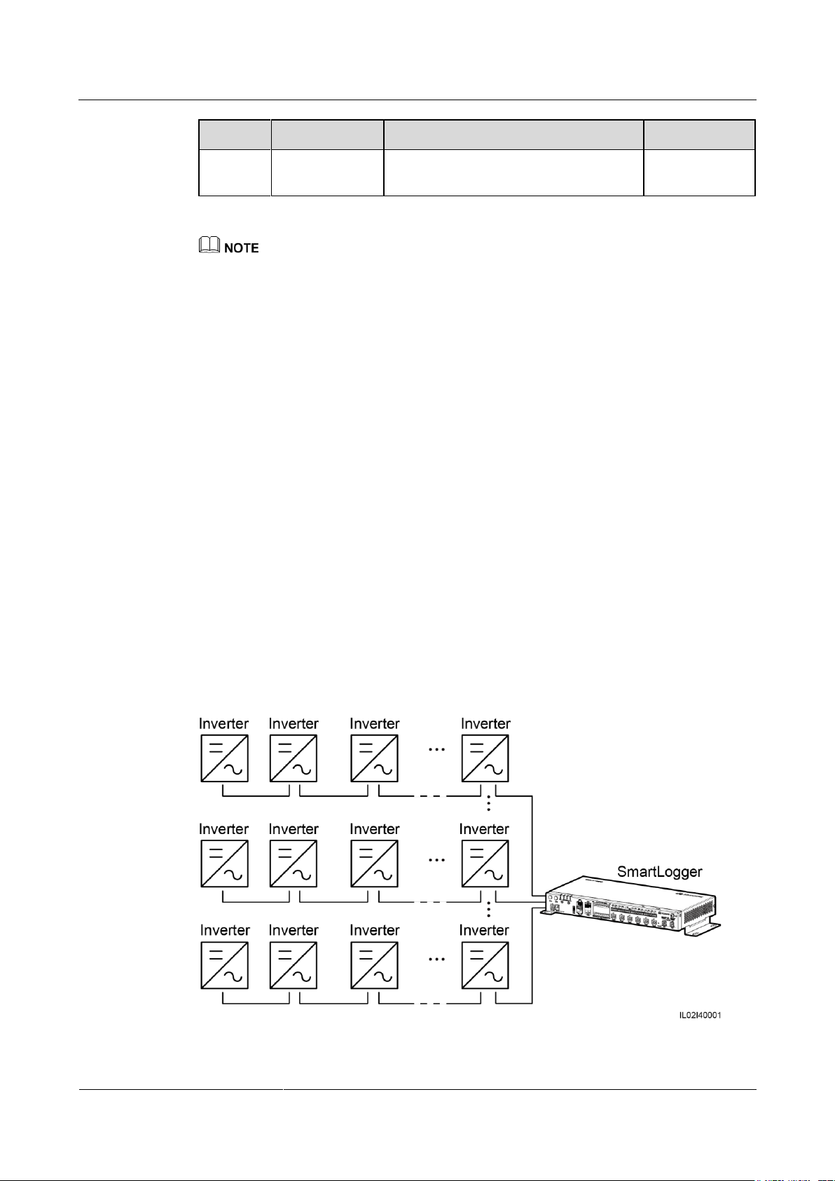
SmartLogger2000-(10-C, 11-C)
User Manual
4 Electrical Connection
Issue Draft A (2017-02-15)
Huawei Proprietary and Confidential
Copyright © Huawei Technologies Co., Ltd.
45
No.
Component
Specifications
Quantity
4
MCB
Rated voltage: ≥ 800 V; rated current: ≥
32 A
1
If the SmartLogger communicates with the SUN2000 through PLC, no RS485 communications
cable needs to be connected between them.
After connecting cables to the AC ports, log in to the embedded WebUI and enable the PLC function
in the SmartLogger. For details, see 7.10.7.1 Connecting Devices. 7.7.4.3 Networking Settings
describes how to configure PLC parameters for the SmartLogger.
The port used for PLC networking is RS485-0. The recommended Baud Rate for the port is 115200
bps, which can provide optimal communications performance.
----End
Follow-up Procedure
Disconnection can be performed in reverse order.
4.5.4 Connecting Multiple SUN2000s
The SmartLogger can connect to multiple SUN2000s through a daisy chain or AC power
cables.
Daisy Chain Connection
In the daisy chain connection mode, the RS485OUT of one SUN2000 is connected to the
RS485IN port of the next SUN2000, and the first SUN2000 is connected to the SmartLogger
as described in 4.5.2 Connecting the SUN2000 Over RS485.
Figure 4-13 Connecting the SmartLogger to multiple SUN2000s
Page 54
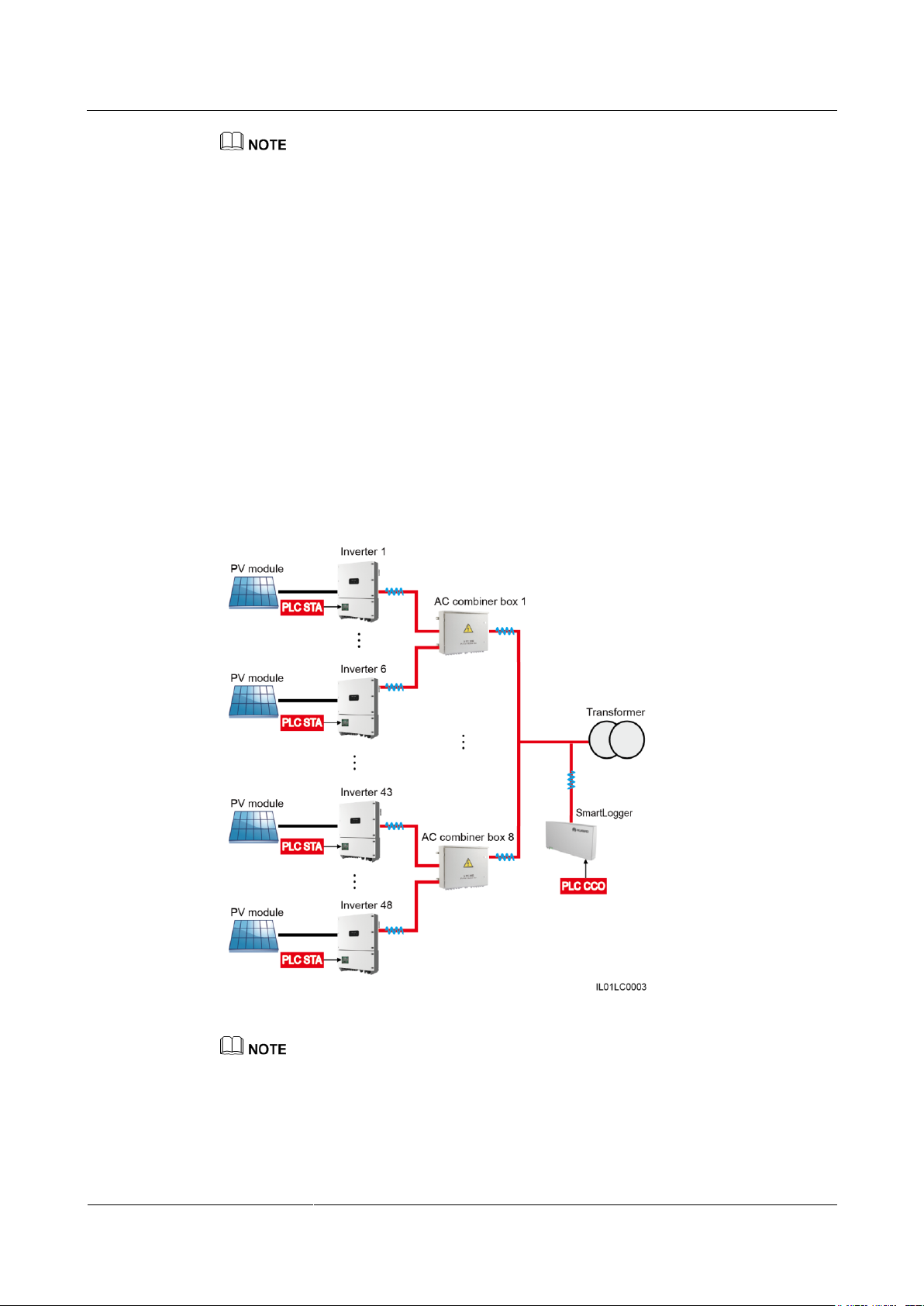
SmartLogger2000-(10-C, 11-C)
User Manual
4 Electrical Connection
Issue Draft A (2017-02-15)
Huawei Proprietary and Confidential
Copyright © Huawei Technologies Co., Ltd.
46
Each SmartLogger can connect to a maximum of 200 devices. You are advised to connect less than
30 devices to each RS485 route. Each SmartLogger can connect to a maximum of 150 SUN2000s.
If an EMI is to be connected, connect it at the end of the chain.
Set Build-out Resistor to Enable under Comm. Param. for the SUN2000 at the end of each daisy
chain. For details, see SUN2000 APP User Manual.
The IP addresses for all devices in the daisy chain should be within the searching segment set in the
SmartLogger and they must differ from each other. Otherwise, the communication would fail
between the devices and the SmartLogger.
You can perform the Auto Assign Address operation on the built-in WebUI of the SmartLogger. If
an RS485 address conflict is detected for SUN2000s, the SmartLogger automatically reassigns
addresses without the need for local address upgrade for the SUN2000s.
The values of Baud rate for all the devices in each daisy chain should stay consistent with the baud
rate of the SmartLogger.
AC Power Cable Connection
Figure 4-14 shows the method for connecting the SmartLogger to multiple SUN2000s over
AC power cables.
Figure 4-14 PLC networking
If the SmartLogger communicates with the SUN2000 over PLC, ensure that the SUN2000 with PLC
is used.
If the SmartLogger communicates with the SUN2000 over PLC, one SmartLogger can connect to a
maximum of 80 SUN2000s over the built-in PLC CCO. If the SmartLogger is also connected to an
external PLC CCO over the COM port, one SmartLogger can connect to a maximum of 150
SUN2000s.
Page 55
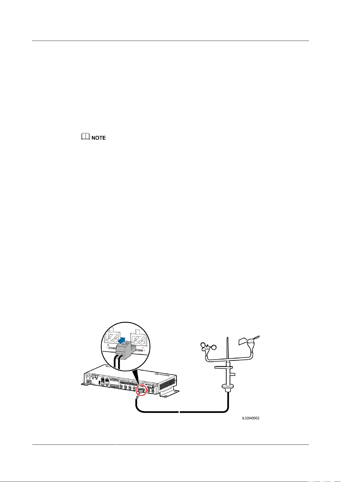
SmartLogger2000-(10-C, 11-C)
User Manual
4 Electrical Connection
Issue Draft A (2017-02-15)
Huawei Proprietary and Confidential
Copyright © Huawei Technologies Co., Ltd.
47
4.6 Connecting an EMI
4.6.1 Connection Description
There are two types of EMIs. One is a standard EMI that supports Modbus-RTU, and the
other is a split-type EMI that consists of various sensors.
The SmartLogger connects a standard or split-type EMI that supports Modbus-RTU over a
COM port, connects to a split-type EMI composed of current or voltage-type sensors over an
AI port, and connects to a PT100/PT1000 temperature sensor over a PT port. The connection
mode depends on site requirements.
The recommended connection methods are as follows:
Connect over a COM port if a COM or AI port is to be connected.
Connect a current-type AI port if an AI port is to be connected.
One SmartLogger can manage multiple EMIs or multiple groups of EMIs.
4.6.2 Connecting the SmartLogger to an EMI That Supports Standard Modbus-RTU
Context
Devices from different vendors may support different protocol specifications. To normally
obtain information from the connected EMI, correctly configure the protocol specifications on
the WebUI of the SmartLogger based on the protocol specifications delivered by the vendor.
For the definition of the RS485 communications cable for the EMI, see the delivered
operation guide.
The SmartLogger provides six RS485 communications ports. For the port descriptions, see
4.5.2 Connecting the SUN2000 Over RS485.
Figure 4-15 shows how to connect the SmartLogger to an EMI over an RS485
communications cable.
Figure 4-15 Connecting the SmartLogger to an EMI
Page 56

SmartLogger2000-(10-C, 11-C)
User Manual
4 Electrical Connection
Issue Draft A (2017-02-15)
Huawei Proprietary and Confidential
Copyright © Huawei Technologies Co., Ltd.
48
Procedure
Step 1 Connect one end of the cable delivered with the EMI to the RS485 port of the EMI.
Step 2 Connect the other end of the cable to the COM port of the SmartLogger. For details, see 4.3
Connecting Cables to the Terminal Block on the COM Port.
When connecting cables, ensure that the RS485+ and RS485- ports on the EMI respectively
connect to the COM+ and COM- ports on the SmartLogger.
The EMI cannot be automatically identified. After connecting cables, log in to the embedded WebUI
and manually add the EMI. For details, see 7.10.7.1 Connecting Devices. Set Device Type to EMI
and Comm.protocal to Modbus-RTU.
After adding an EMI, set its parameters. For details, see Connection over the COM Port in 7.7.5.2
Setting Running Parameters. The EMI model is Jingzhou Yangguang (PC-4), Handan (RYQ-3),
Kipp&Zonen SMPx or Lufft WSx-UMB.
If the SmartLogger needs to be connected to an EMI and multiple SUN2000s, connect the EMI at
the end of the daisy chain, and verify that the port connected to the EMI has a unique
communications address. For the daisy chain connection, see Daisy Chain Connection in 4.5.4
Connecting Multiple SUN2000s.
----End
Follow-up Procedure
Disconnection can be performed in reverse order.
4.6.3 Connecting the SmartLogger to a Split EMI
Connecting to an EMI over a COM Port
The EMI used in Europe and Southeast Asia is composed of sensors, whose signals need to be
converted into RS485 signals (Modbus-RTU) over an extra analog-to-digital converter before
the sensors are connected to the SmartLogger.
The analog-to-digital converter should provide an RS485 port and support the standard
Modbus-RTU protocol. This section describes the connection between the SmartLogger and a
split EMI through the ADAM4117 that functions as an analog-to-digital converter.
The SmartLogger provides six RS485 communications ports. For the port descriptions, see
4.5.2 Connecting the SUN2000 Over RS485.
Figure 4-16 shows how to connect the SmartLogger to a split EMI over an analog-to-digital
converter.
Page 57
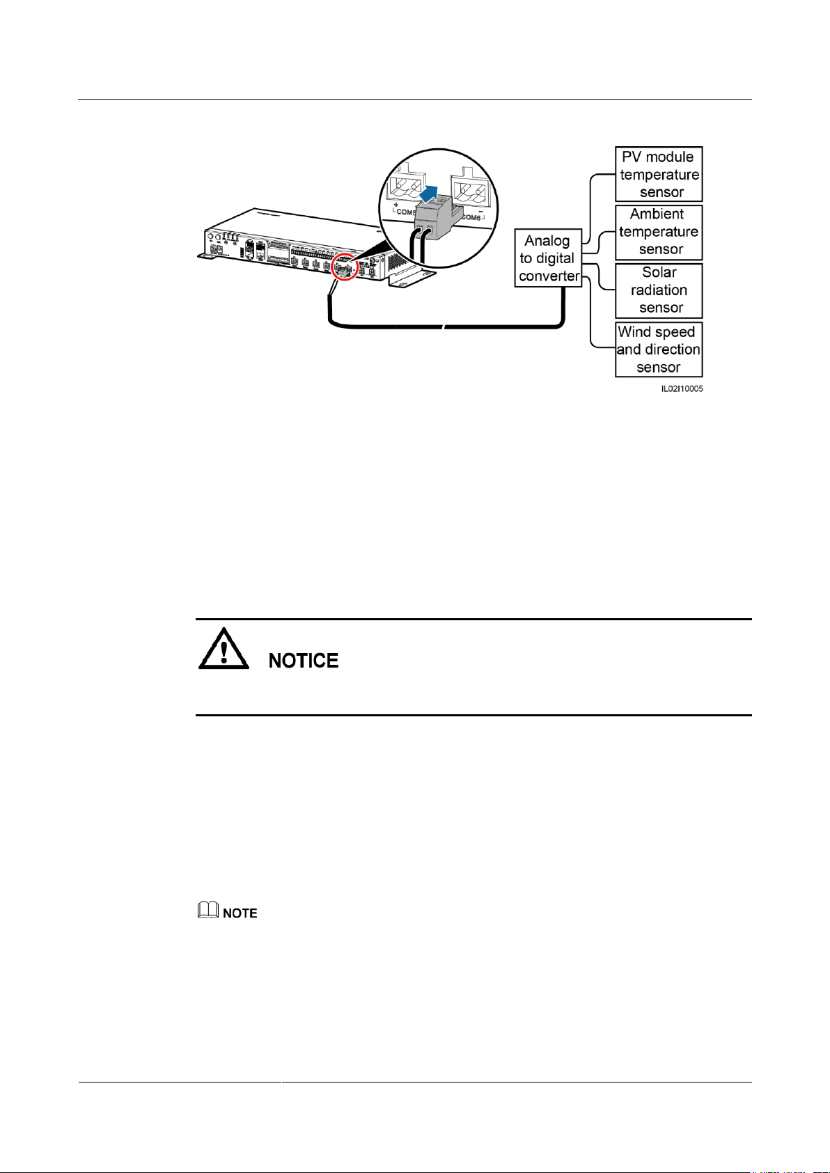
SmartLogger2000-(10-C, 11-C)
User Manual
4 Electrical Connection
Issue Draft A (2017-02-15)
Huawei Proprietary and Confidential
Copyright © Huawei Technologies Co., Ltd.
49
Figure 4-16 Connecting the SmartLogger to a split EMI (1)
Step 1 Prepare a cable with an appropriate length, strip a proper part of the insulation layer from one
end, and connect the end to the port on the analog-to-digital converter.
The DJYP2VP2-22 2x2x1 computer cable or a communications cable with a conductor
cross-sectional area of 1 mm2 and outer diameter of 14–18 mm is recommended.
For detailed operations, see the document delivered with the analog-to-digital converter.
Step 2 Connect the other end of the cable to the COM port of the SmartLogger. For details, see 4.3
Connecting Cables to the Terminal Block on the COM Port.
When connecting cables, ensure that the RS485+ and RS485– ports on the analog-to-digital
converter respectively connect to the COM+ and COM– ports on the SmartLogger.
Step 3 The Baud Rate settings for the analog-to-digital converter and SmartLogger must be the
same.
For SmartLogger communication parameter settings, see 7.9.2.2 Setting RS485
Parameters or the SUN2000 APP User Manual.
For details about the communications parameter configurations for the analog-to-digital
converter, see the delivered document.
Step 4 Connect each sensor to the analog-to-digital converter. For detailed operations, see the
documents delivered with the analog-to-digital converter or sensors.
The EMI cannot be automatically identified. After connecting cables, log in to the embedded WebUI
and manually add the EMI. For details, see 7.10.7.1 Connecting Devices. Set Device Type to EMI
and Comm.protocal to Modbus-RTU.
After adding an EMI, set its parameters. For details, see Connection over the COM Port in 7.7.5.2
Setting Running Parameters. The EMI model is Sensor(ADAM).
Page 58
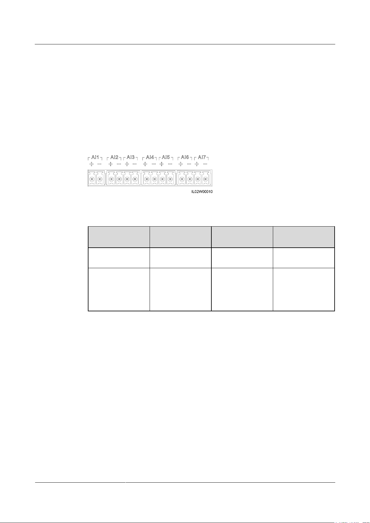
SmartLogger2000-(10-C, 11-C)
User Manual
4 Electrical Connection
Issue Draft A (2017-02-15)
Huawei Proprietary and Confidential
Copyright © Huawei Technologies Co., Ltd.
50
Port
Current/Voltage-T
ype
AI Signal Input
Range
Remarks
AI1
Voltage-type
0–10 V (passive)
Connects to a
voltage-type sensor.
AI2–AI7
Current-type
0–20 mA, 4–20 mA
(passive)
Connects to a
current-type sensor
that needs to be
energized
separately.
If the SmartLogger needs to be connected to an EMI and multiple SUN2000s, connect the EMI at
the end of the daisy chain, and verify that the port connected to the EMI has a unique
communications address. For the daisy chain connection, see Daisy Chain Connection in 4.5.4
Connecting Multiple SUN2000s.
----End
Connecting to an EMI over an AI Port
The EMI used in Europe and Southeast Asia is composed of sensors that need to connect to
the AI ports on the SmartLogger.
Figure 4-17 AI ports
Table 4-6 AI port definitions
Figure 4-18 shows how to connect the SmartLogger to a split EMI over an AI port.
Page 59
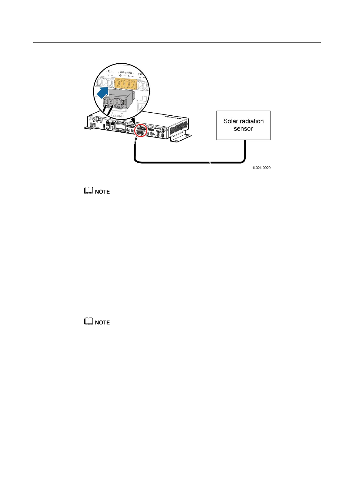
SmartLogger2000-(10-C, 11-C)
User Manual
4 Electrical Connection
Issue Draft A (2017-02-15)
Huawei Proprietary and Confidential
Copyright © Huawei Technologies Co., Ltd.
51
Figure 4-18 Connecting the SmartLogger to a split EMI (2)
One sensor connects to one AI port. Figure 4-18 shows only the connection between the solar
radiation sensor and the SmartLogger. Connections between other sensors and the SmartLogger are
the same.
For details about the cables and cable connection operations, see the documents delivered with the
sensors. The AI port on the SmartLogger is marked + and –. Connect cables correctly according to
the silk screens.
The EMI cannot be automatically identified. After connecting cables, log in to the embedded WebUI
and manually add the EMI. For details, see 7.10.7.1 Connecting Devices. Set Device Type to EMI
and Comm.protocal to AI.
After adding an EMI, set its parameters. For details, see Connection over the AI/PT Port in 7.7.5.2
Setting Running Parameters.
If the SmartLogger needs to be connected to an EMI and multiple SUN2000s, connect the EMI at
the end of the daisy chain, and verify that the port connected to the EMI has a unique
communications address. For the daisy chain connection, see Daisy Chain Connection in 4.5.4
Connecting Multiple SUN2000s.
Connecting to a PT100/PT1000 Temperature Sensor over the PT Port
The SmartLogger provides two PT ports. The PT1 port can connect to a three-wire or two-wire
temperature sensor, whereas the PT2 port can connect to only a two-wire PT100/PT1000
temperature sensor (PT100/PT1000 for short).
If the AI port has been connected to a temperature sensor, the PT port can be reserved.
If the PT1 port connects to a two-wire PT100/PT1000 temperature sensor, you need to short-circuit
the GND port to one – port using the delivered short-circuit cable.
For details about the cables and cable connection operations, see the documents delivered with the
PT100/PT1000. The PT port on the SmartLogger is marked + and –. Connect cables correctly
according to the silk screens.
The PT1 port is used as an example. Figure 4-19 and Figure 4-20 show how to connect the
SmartLogger to the PT100/PT1000.
Page 60
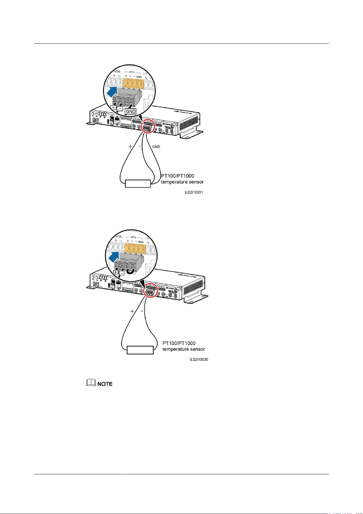
SmartLogger2000-(10-C, 11-C)
User Manual
4 Electrical Connection
Issue Draft A (2017-02-15)
Huawei Proprietary and Confidential
Copyright © Huawei Technologies Co., Ltd.
52
Figure 4-19 Connecting to a three-wire PT100/PT1000
Figure 4-20 Connecting to a two-wire PT100/PT1000
The EMI cannot be automatically identified. After connecting cables, log in to the embedded WebUI
and manually add the EMI. For details, see 7.10.7.1 Connecting Devices. Set Device Type to EMI
and Comm. protocol to AI.
After adding an EMI, set its parameters. For details, see Connection over the AI/PT Port in 7.7.5.2
Setting Running Parameters.
Page 61
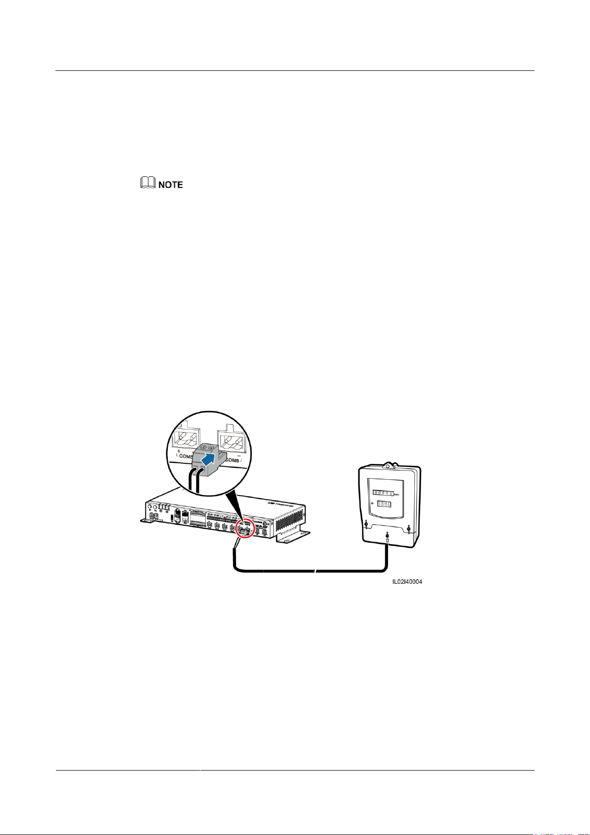
SmartLogger2000-(10-C, 11-C)
User Manual
4 Electrical Connection
Issue Draft A (2017-02-15)
Huawei Proprietary and Confidential
Copyright © Huawei Technologies Co., Ltd.
53
4.7 Connecting a Power Meter
Context
The SmartLogger can be connected to a power meter that supports the standard Modbus-RTU
or DL/T645 protocol.
The SmartLogger can be connected to and manage only one power meter that supports the
Modbus-RTU protocol.
The SmartLogger can be connected to and manage multiple power meters that support the DL/T645
protocol.
Devices from different vendors may support different protocol specifications. To obtain
information from the connected power meter, correctly configure the protocol specifications
on the WebUI of the SmartLogger based on the protocol specifications delivered by the
vendor.
For the definition of the RS485 communications cable for the power meter, see the delivered
operation guide.
The SmartLogger provides six RS485 communications ports. For the port descriptions, see
4.5.2 Connecting the SUN2000 Over RS485.
Procedure
Step 1 Connect one end of the cable delivered with the power meter to the RS485 port of the power
Figure 4-21 shows how to connect the SmartLogger to a power meter.
Figure 4-21 Connecting the SmartLogger to a power meter
meter.
Step 2 Connect the other end of the cable to the COM port of the SmartLogger. For details, see 4.3
Connecting Cables to the Terminal Block on the COM Port.
Page 62

SmartLogger2000-(10-C, 11-C)
User Manual
4 Electrical Connection
Issue Draft A (2017-02-15)
Huawei Proprietary and Confidential
Copyright © Huawei Technologies Co., Ltd.
54
When connecting cables, ensure that the RS485+ and RS485- ports on the power meter
respectively connect to the COM+ and COM- ports on the SmartLogger.
After connecting cables to the power meter that supports Modbus-RTU, log in to the embedded
WebUI and set parameters for Modbus Meter. For details, see 7.9.2.3 Setting Power Meter
Parameters.
Devices connected to a same COM port of the SmartLogger must support the same protocol. After
connecting cables, log in to the embedded WebUI and modify the COM port protocol. For details,
see 7.9.2.2 Setting RS485 Parameters.
A power meter cannot be detected automatically. You need to add this device manually. For details,
see 7.10.7.1 Connecting Devices. Set Device Type to Meter and Comm.protocal to the protocol
supported by the connected power meter.
After modifying the protocol for a DL/T645 power meter and adding it manually, log in to the
embedded WebUI to query and set parameters for DL/T645 Meter. For details, see 7.7.6 Power
Meter.
----End
Follow-up Procedure
Disconnection can be performed in reverse order.
4.8 Connecting a Box-type Transformer
Context
The SmartLogger can be connected to a box-type transformer over the RS485 and Ethernet
communication modes.
The SmartLogger provides two Ethernet electrical ports. A box-type transformer that supports Ethernet
communication can be connected to the SmartLogger through an Ethernet electrical port, and then to an
NMS through the northbound interface of the SmartLogger. In this connection mode, the IP addresses of
the SmartLogger and the box-type transformer must be in the same network segment.
This section describes how to connect a box-type transformer that supports the Modbus-RTU
or IEC103 protocol to the SmartLogger using the RS485 communication mode.
Devices from different vendors may support different protocol specifications. To obtain
information from the connected box-type transformer, correctly configure the protocol
specifications on the WebUI of the SmartLogger based on the protocol specifications
delivered by the vendor.
For the definition of the RS485 communications cable for the box-type transformer, see the
delivered operation guide.
The SmartLogger provides six RS485 communications ports. For the port descriptions, see
4.5.2 Connecting the SUN2000 Over RS485.
Figure 4-22 shows how to connect the SmartLogger to a box-type transformer over an RS485
communications cable.
Page 63
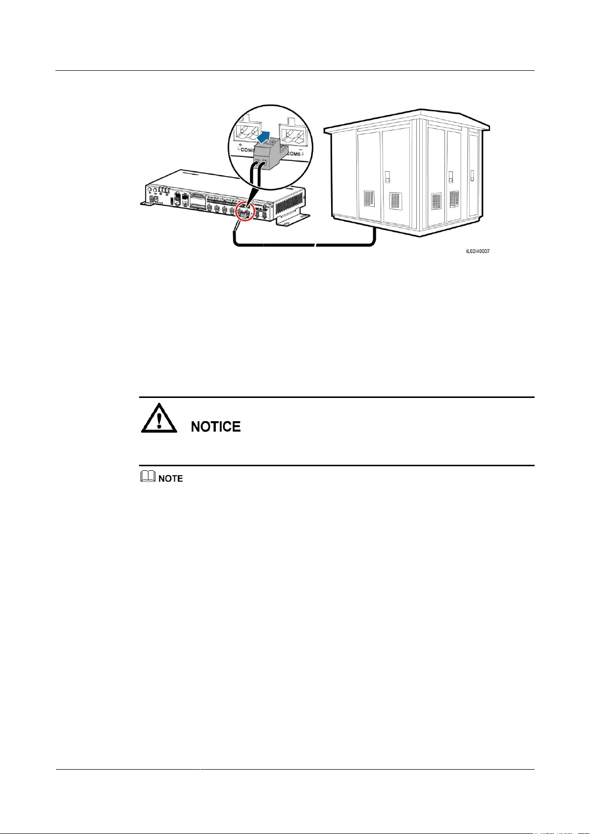
SmartLogger2000-(10-C, 11-C)
User Manual
4 Electrical Connection
Issue Draft A (2017-02-15)
Huawei Proprietary and Confidential
Copyright © Huawei Technologies Co., Ltd.
55
Procedure
Step 1 Connect one end of the cable delivered with the box-type transformer to the RS485 port of the
Step 2 Connect the other end of the cable to the COM port of the SmartLogger. For details, see 4.3
Figure 4-22 Connecting the SmartLogger to a box-type transformer
box-type transformer.
Connecting Cables to the Terminal Block on the COM Port.
When connecting cables, ensure that the RS485+ and RS485- ports on the box-type
transformer respectively connect to the COM+ and COM- ports on the SmartLogger.
Devices connected to a same COM port of the SmartLogger must support the same protocol.
After connecting cables, log in to the embedded WebUI and set parameters for Box-type
Transformer. For details, see 7.7.8 Custom Device.
----End
Follow-up Procedure
Disconnection can be performed in reverse order.
4.9 Connecting a PID Module
Context
The PID module is used to prevent PV module output power degradation due to the potential
induced degradation (PID) effect in a PV power system.
The SmartLogger can be connected to and manage only one PID module that supports the
Modbus-RTU protocol.
Page 64
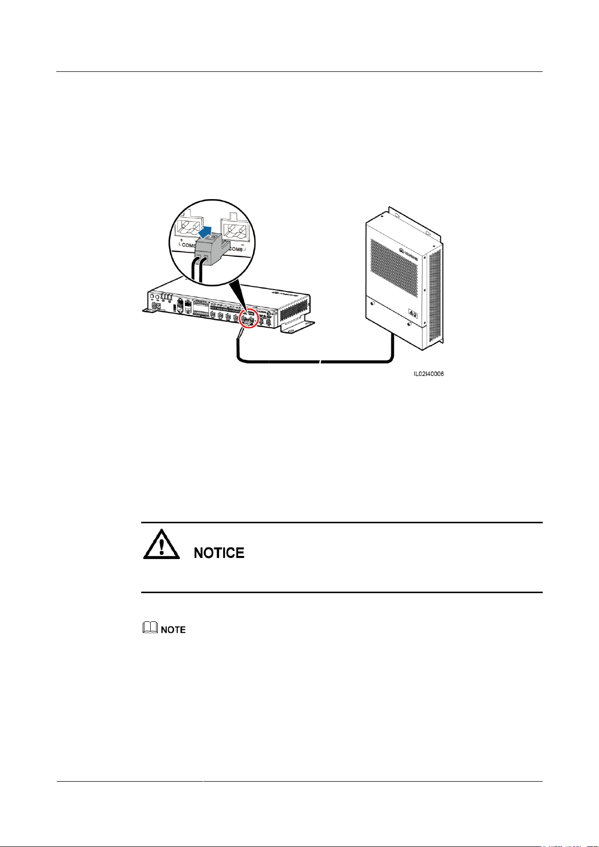
SmartLogger2000-(10-C, 11-C)
User Manual
4 Electrical Connection
Issue Draft A (2017-02-15)
Huawei Proprietary and Confidential
Copyright © Huawei Technologies Co., Ltd.
56
For the definition of the RS485 communications cable for the PID module, see the delivered
operation guide.
The SmartLogger provides six RS485 communications ports. For the port descriptions, see
4.5.2 Connecting the SUN2000 Over RS485.
Figure 4-23 shows how to connect the SmartLogger to a PID module.
Figure 4-23 Connecting the SmartLogger to a PID module
Procedure
Step 1 Connect one end of the cable delivered with the PID module to the RS485 port of the PID
Step 2 Connect the other end of the cable to the COM port of the SmartLogger. For details, see 4.3
Step 3 The Baud rate settings for the PID module and SmartLogger must be the same.
module.
Connecting Cables to the Terminal Block on the COM Port.
When connecting cables, ensure that the brown cable (RS485A) and black cable (RS485B) of
the PID module respectively connect to the COM+ and COM– ports on the SmartLogger.
The baud rates supported by the PID module include 4800 bit/s, 9600 bit/s, 19,200 bit/s, and 115,200
bit/s.
The PID module supports automatic address allocation. After connecting cables, log in to the
embedded WebUI and search for the PID module by clicking Auto. Search in 7.10.7.1 Connecting
Devices.
For details about PID parameter settings, see 7.7.7.2 Setting Running Parameters in 7.7.7 PID.
The default RS485 communications address of the PID module is 1. To change the RS485
communications address, log in to the embedded WebUI and click Auto Assign Address in 7.10.7.1
Connecting Devices.
Page 65
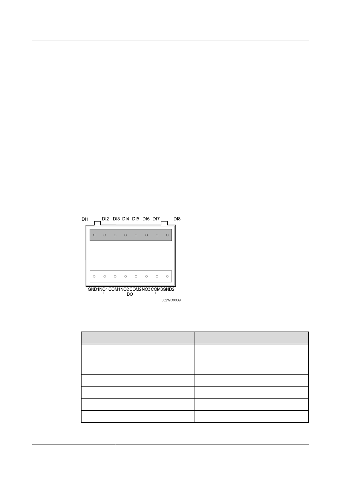
SmartLogger2000-(10-C, 11-C)
User Manual
4 Electrical Connection
Issue Draft A (2017-02-15)
Huawei Proprietary and Confidential
Copyright © Huawei Technologies Co., Ltd.
57
----End
Port
Function
GND1
Dry contact input common terminal 1, used
for active power derating for DI1–DI4
DI1
DI_1
DI2
DI_2
DI3
DI_3
DI4
DI_4
DI5
DI_5
Follow-up Procedure
Disconnection can be performed in reverse order.
4.10 Connecting a Ripple Control Receiver
Prerequisites
You have prepared two-core or multiple-core cables with a cross sectional area of 1.5 mm2
(recommended).
Context
In Germany and some European areas, a ripple control receiver is used to convert a power
grid dispatching signal to a dry contact signal. The dry contact is required for receiving the
power grid dispatching signal.
Figure 4-24 DI ports of the SmartLogger
Table 4-7 DI port description
Page 66
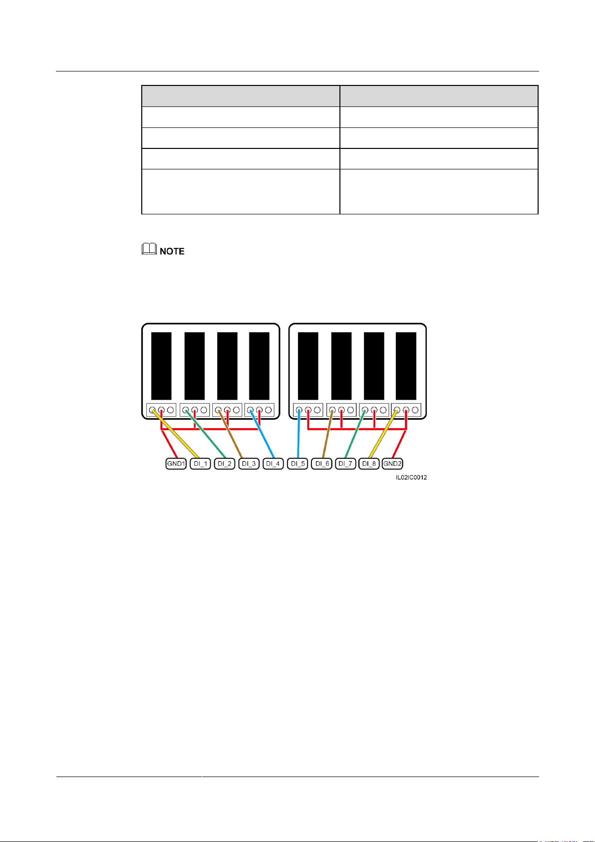
SmartLogger2000-(10-C, 11-C)
User Manual
4 Electrical Connection
Issue Draft A (2017-02-15)
Huawei Proprietary and Confidential
Copyright © Huawei Technologies Co., Ltd.
58
Port
Function
DI6
DI_6
DI7
DI_7
DI8
DI_8
GND2
Dry contact input common terminal 2, used
for reactive power compensation for
DI5–DI8
DI1–DI4 are used for active power derating, and DI5–DI8 are used for reactive power compensation.
Figure 4-25 shows how to connect the SmartLogger to a ripple control receiver.
Figure 4-25 Connecting a ripple control receiver
Procedure
Step 1 Connect one end of the cable to the ripple control receiver.
Step 2 Strip 8 mm of the insulation layer at the other end of the cable.
Step 3 Remove the terminal block from the DI port.
Page 67
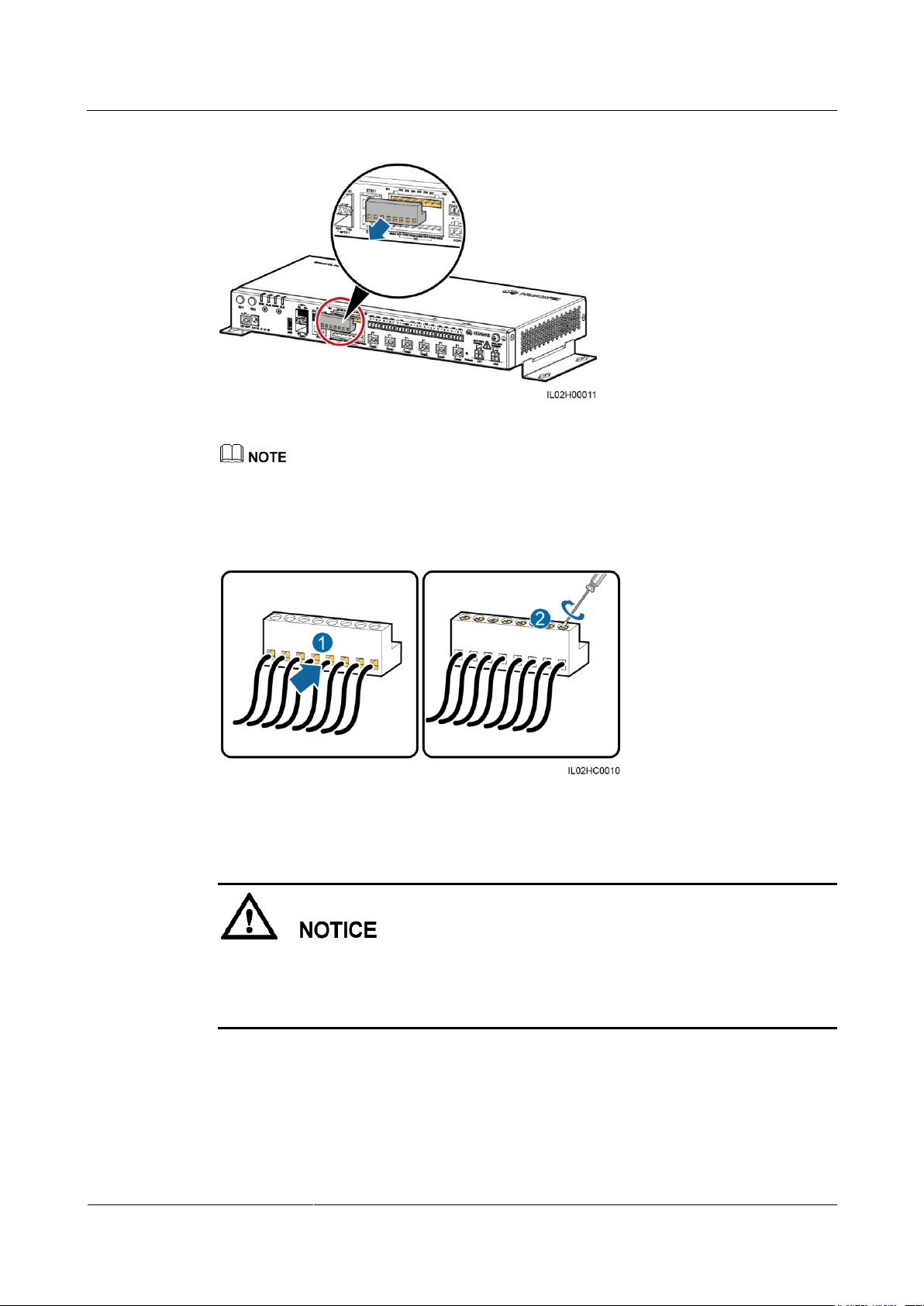
SmartLogger2000-(10-C, 11-C)
User Manual
4 Electrical Connection
Issue Draft A (2017-02-15)
Huawei Proprietary and Confidential
Copyright © Huawei Technologies Co., Ltd.
59
Figure 4-26 Removing the terminal block
Use a flat-head screwdriver to remove the terminal block.
Step 4 Connect cables to the terminal block and secure the cables.
Figure 4-27 Connecting cables
Step 5 Insert the terminal block into the DI port.
To enable the power grid dispatching function, you need to set the corresponding parameter
(for Active Power Control or Reactive Power Control) on the embedded WebUI after
connecting cables. For details, see 8.1.1 Active Power Control or 8.1.2 Reactive Power
Control.
----End
Follow-up Procedure
Disconnection can be performed in reverse order.
Page 68
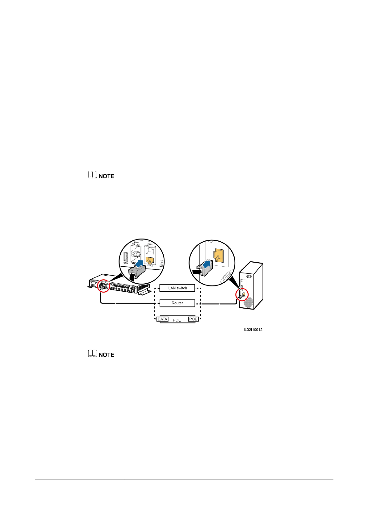
SmartLogger2000-(10-C, 11-C)
User Manual
4 Electrical Connection
Issue Draft A (2017-02-15)
Huawei Proprietary and Confidential
Copyright © Huawei Technologies Co., Ltd.
60
4.11 Connecting an Ethernet Network Cable
Context
The SmartLogger provides two Ethernet electrical ports, through which the SmartLogger
can connect to a third-party device.
The SmartLogger can be connected to an Ethernet switch, router, or POE module. It can
also be connected to the Ethernet electrical port of a PC directly or through a hub. Select
the device to be connected based on the actual networking scenario. For details on
typical scenarios, see 2.4 Typical Networking Scenarios.
Procedure
Step 1 Connect one end of the delivered network cable to the Ethernet electrical port of a device.
If the delivered cable is too short, pay attention to the following when preparing a cable:
Select a CAT 5E or higher-class shielded network cable.
The cable length should not exceed 100 m.
Step 2 Connect the other end of the network cable to ETH1 or ETH2 of the SmartLogger.
Figure 4-28 Connecting an Ethernet network cable
A POE module needs to be connected to the DATA port of the SmartLogger.
The default IP address of the SmartLogger is 192.168.0.10, the default subnet mask is 255.255.255.0,
and the default gateway is 192.168.0.1.
If the SmartLogger is connected to a PC directly or through a hub, set the IP addresses of the
SmartLogger and PC in the same network segment. For example, if the IP address of the
SmartLogger is 192.168.0.10, set the IP address of the PC to 192.168.0.11. The subnet mask and the
gateway of the PC should be consistent with those of the SmartLogger.
If the SmartLogger is connected to a PC through a networking device (such as a router), set the IP
addresses of the SmartLogger and networking device in the same network segment. Set the gateway
of the SmartLogger correctly so that it can communicate with the networking device.
To enable communication between the SmartLogger and the NetEco, set NetEco parameters
properly on the SmartLogger. For details, see 7.9.2.4 Setting NetEco Parameters.
----End
Page 69
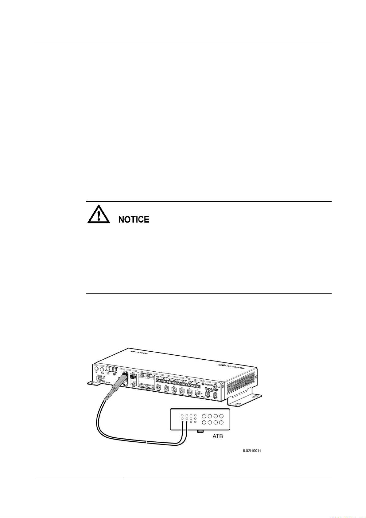
SmartLogger2000-(10-C, 11-C)
User Manual
4 Electrical Connection
Issue Draft A (2017-02-15)
Huawei Proprietary and Confidential
Copyright © Huawei Technologies Co., Ltd.
61
Follow-up Procedure
Disconnection can be performed in reverse order.
4.12 Connecting Fiber Jumpers
Context
The SmartLogger can be connected to devices such as an ATB through fiber jumpers. You can
select the devices to be connected based on the actual networking scenario. For details on
typical scenarios, see 2.4 Typical Networking Scenarios.
Procedure
Step 1 Insert the optical module into SFP1 or SFP2 of the SmartLogger.
An optical module is optional. A 100M optical module (eSFP, 1310 nm, and single mode)
with transmission distance of at least 15 km is recommended.
When inserting an optical module into the SFP1 port, verify that the side with a handle
faces upwards. When inserting an optical module into the SFP2 port, verify that the side
with a handle faces downwards.
The optical switch used for the central control room supports RSTP and STP. To ensure the
communication between the optical switch and the SmartLogger, the configured optical
module must have a transmission speed of 100 Mbit/s.
Step 2 Connect the two fiber jumpers delivered with the optical module to the ports on the optical
module.
Step 3 Connect the other end of the fiber jumper to the port on the ATB.
Figure 4-29 Connecting an ATB
Page 70
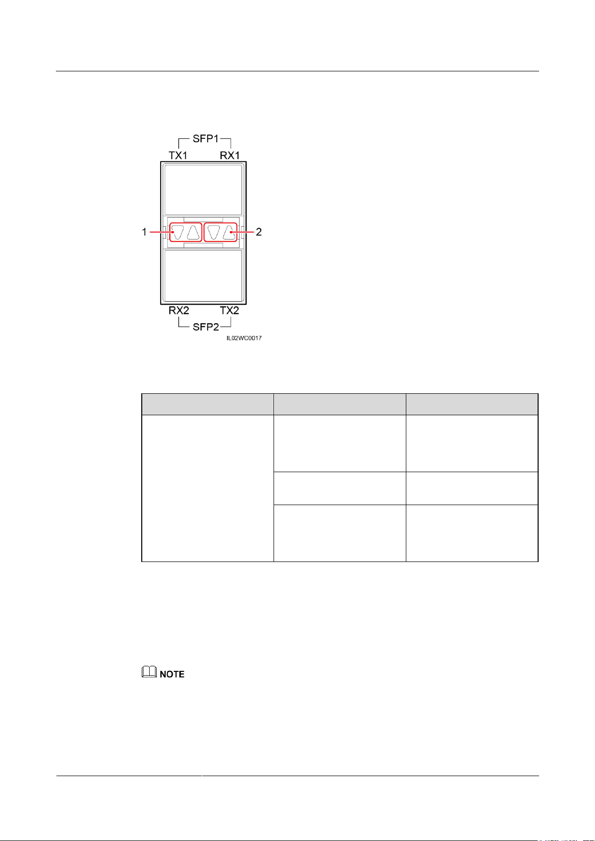
SmartLogger2000-(10-C, 11-C)
User Manual
4 Electrical Connection
Issue Draft A (2017-02-15)
Huawei Proprietary and Confidential
Copyright © Huawei Technologies Co., Ltd.
62
Step 4 Determine the operating status based on the Ethernet optical port indicators.
Indicator
Status
Meaning
(1) Upper port
(2) Lower port
Green steady on and
blinking yellow at short
intervals (0.1s on and 0.1s
off)
An optical module has been
inserted into the Ethernet
optical port.
Green steady on and yellow
off
A fiber link has been
successfully established.
Green steady on and
blinking yellow at long
intervals (0.1s on and 1.9s
off)
Optical fiber communication
is in progress.
Figure 4-30 Ethernet optical port indicators
Table 4-8 Ethernet optical port indicator description
----End
Follow-up Procedure
Disconnection can be performed in reverse order.
1.
When removing a fiber jumper, press down the clip first.
2.
When removing an optical module, press down the handle and pull the module outwards.
Page 71
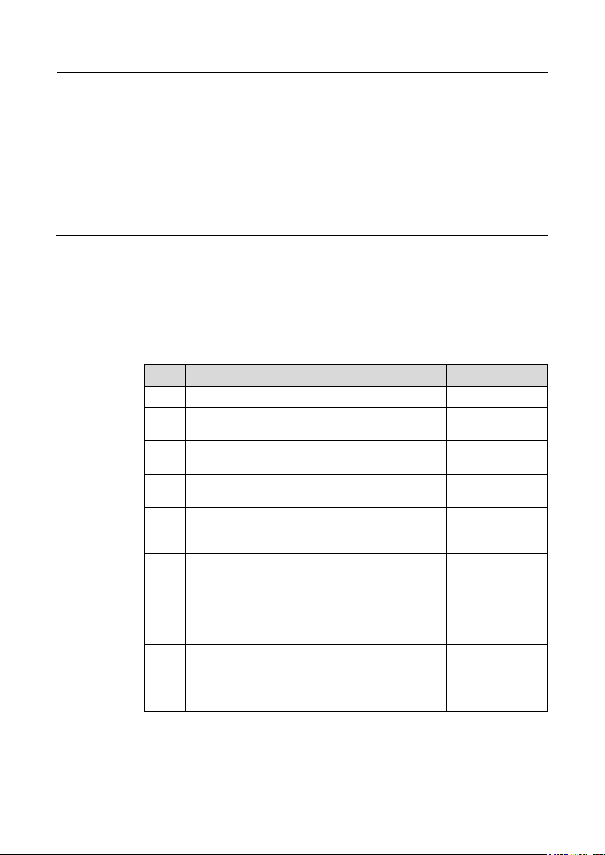
SmartLogger2000-(10-C, 11-C)
User Manual
5 System Operation
Issue Draft A (2017-02-15)
Huawei Proprietary and Confidential
Copyright © Huawei Technologies Co., Ltd.
63
5 System Operation
No.
Check That
Check Result
1
The SmartLogger is installed correctly and reliably.
□ Passed □ Failed
2
Ground cables of the SmartLogger are connected to
ground points securely and reliably.
□ Passed □ Failed
3
The cables between the SmartLogger and other devices
are connected securely and reliably.
□ Passed □ Failed
4
The RS485 communications cable is connected securely
and reliably.
□ Passed □ Failed
5
The AC power cable is securely and reliably connected to
the SmartLogger when the AC power cable is used for
communication.
□ Passed □ Failed
6
Ports that are not used (such as RF1, RF2, Ethernet
optical port, and Ethernet port) are protected by dustproof
plugs.
□ Passed □ Failed
7
Routing for the power cable and signal cable meets the
requirements for routing strong-current and weak-current
cables and complies with the cable routing plan.
□ Passed □ Failed
8
Cables are bound neatly, and cable ties are secured evenly
and properly in the same direction.
□ Passed □ Failed
9
There is no unnecessary adhesive tape or cable tie on
cables.
□ Passed □ Failed
5.1 Checking Before Power-On
To ensure that the SmartLogger can work properly after power-on, check the items listed in
Table 5-1 before powering on the SmartLogger.
Table 5-1 Items to be checked for the SmartLogger before power-on
Page 72
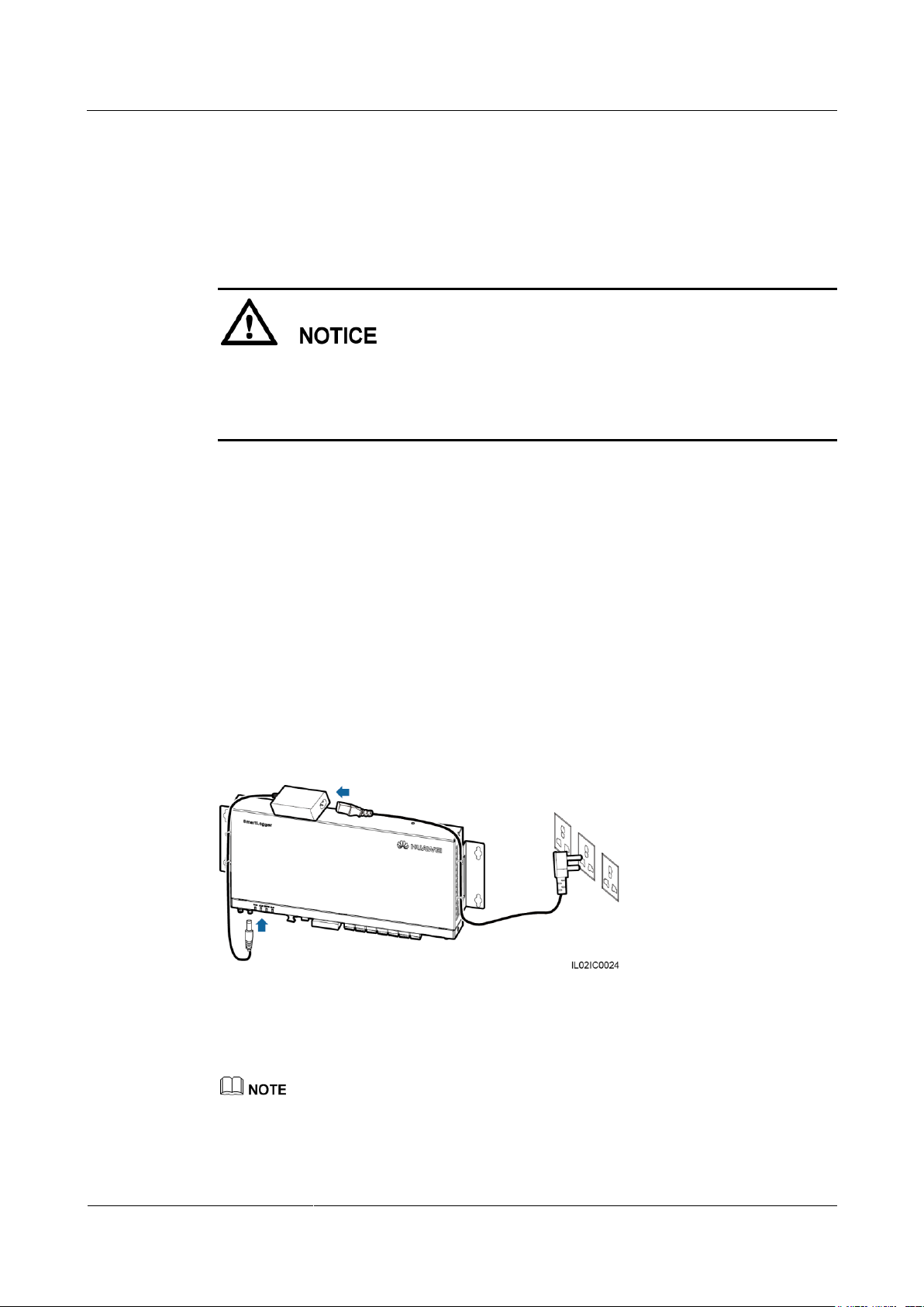
SmartLogger2000-(10-C, 11-C)
User Manual
5 System Operation
Issue Draft A (2017-02-15)
Huawei Proprietary and Confidential
Copyright © Huawei Technologies Co., Ltd.
64
5.2 System Power-On
Prerequisites
You have performed the operations described in 5.1 Checking Before Power-On.
When powering on the system, use the power adapter delivered with the product. The
rated input of the power adapter is 100–240 V AC, and 50 Hz or 60 Hz. If adapters of
other models are used, the equipment may be damaged.
Select an AC socket that matches the power adapter.
Context
In a scenario with a smart array controller, the SmartLogger is installed before delivery, and
the power cable is connected.
Procedure
Step 1 Insert the output terminal of the power adapter into the 12V IN port of the SmartLogger.
Step 2 Insert the power cable into the power adapter.
Step 3 Insert the power cable plug into an AC socket.
Step 4 Switch on the circuit breaker of the AC socket.
In a scenario without a smart array controller, place the power adapter on the top of the
SmartLogger and secure the power adapter using cable ties.
Figure 5-1 Connecting the power cable in a scenario without a smart array controller
Step 5 Switch on the upstream circuit breaker of the AC power cable.
Step 5 needs to be performed in the PLC networking scenario.
----End
Page 73

SmartLogger2000-(10-C, 11-C)
User Manual
6 Man-Machine Interaction
Issue Draft A (2017-02-15)
Huawei Proprietary and Confidential
Copyright © Huawei Technologies Co., Ltd.
65
6 Man-Machine Interaction
6.1 USB Flash Drive Operation
6.1.1 Exporting Data
Context
Procedure
It is recommended that you use a SanDisk, Netac, or Kingston USB flash drive to ensure
compatibility.
By exporting data, you can obtain active alarms, historical alarms, performance data,
exception takeover logs, commissioning logs, operation logs, fault information files, and
electronic labels.
Data can be exported in two methods. Select either method in practice.
Method 1
a. Insert the USB flash drive into the USB port at the bottom of the SmartLogger.
b. Log in to the app, and choose More > System Maintenance > Generate Local
Maint. Script on the main menu page. For details, see the SUN2000 APP User
Manual.
The generated boot script file is automatically saved in the root directory of the USB flash drive.
c. Remove the USB flash drive from the USB port at the bottom of the SmartLogger,
and insert the USB flash drive into the port again.
After the USB flash drive is connected again, the SmartLogger can automatically detect the boot script
file.
d. The SmartLogger automatically executes all commands specified in the boot script
file. View the LED indicator to determine the operating status.
Page 74
SmartLogger2000-(10-C, 11-C)
User Manual
6 Man-Machine Interaction
Issue Draft A (2017-02-15)
Huawei Proprietary and Confidential
Copyright © Huawei Technologies Co., Ltd.
66
Indicator (Silk Screen)
Status
Meaning
ALM
Green off
No local maintenance is in
progress.
Blinking green at long
intervals (1s on and 1s off)
Local maintenance is in
progress.
Green steady on
Local maintenance
succeeds.
Blinking green at short
intervals (0.125s on and
0.125s off)
Local maintenance fails.
Verify that the USB flash drive contains a boot script file; otherwise, the SmartLogger
cannot execute the operations.
If SmartLoggers have the same app login password, the boot script file generated by one
SmartLogger can be imported to other SmartLoggers by using a USB flash drive.
The initial app login password of the SmartLogger is 00000a. Change it upon the first
login.
Table 6-1 LED indicator description
Method 2
a. Insert the USB flash drive into the USB port at the bottom of the SmartLogger.
b. Log in to the app, and choose More > Device Logs on the main menu. For details,
see the SUN2000 APP User Manual.
c. The SmartLogger automatically executes commands. The LED indicator status
reflects the execution situation. For details, see the Table 6-1.
----End
6.1.2 Exporting All Files
Context
It is recommended that you use a SanDisk, Netac, or Kingston USB flash drive to ensure
compatibility.
If the SmartLogger needs to be replaced, you can export all the files before the replacement and then
import the files into the new SmartLogger to ensure data integrity.
After exporting all files, you can view information about the SmartLogger and devices connecting to
the SmartLogger.
Page 75
SmartLogger2000-(10-C, 11-C)
User Manual
6 Man-Machine Interaction
Issue Draft A (2017-02-15)
Huawei Proprietary and Confidential
Copyright © Huawei Technologies Co., Ltd.
67
Procedure
Indicator (Silk Screen)
Status
Meaning
ALM
Green off
No local maintenance is in
progress.
Blinking green at long
intervals (1s on and 1s off)
Local maintenance is in
progress.
Green steady on
Local maintenance
succeeds.
Blinking green at short
intervals (0.125s on and
0.125s off)
Local maintenance fails.
Step 1 Insert the USB flash drive into the USB port at the bottom of the SmartLogger.
Step 2 Log in to the app, and choose More > System Maintenance > Generate Local Maint.
Step 3 Remove the USB flash drive from the USB port at the bottom of the SmartLogger, and insert
Step 4 The SmartLogger automatically executes all commands specified in the boot script file. View
Script on the main menu page. For details, see the SUN2000 APP User Manual.
The generated boot script file is automatically saved in the root directory of the USB flash drive.
the USB flash drive into the port again.
After the USB flash drive is connected again, the SmartLogger can automatically detect the boot script
file.
the LED indicator to determine the operating status.
Verify that the USB flash drive contains a boot script file; otherwise, the SmartLogger
cannot execute the operations.
If SmartLoggers have the same app login password, the boot script file generated by one
SmartLogger can be imported to other SmartLoggers by using a USB flash drive.
The initial app login password of the SmartLogger is 00000a. Change it upon the first
login.
Table 6-2 LED indicator description
----End
Page 76
SmartLogger2000-(10-C, 11-C)
User Manual
6 Man-Machine Interaction
Issue Draft A (2017-02-15)
Huawei Proprietary and Confidential
Copyright © Huawei Technologies Co., Ltd.
68
6.1.3 Importing All Files
Indicator (Silk Screen)
Status
Meaning
ALM
Green off
No local maintenance is in
progress.
Blinking green at long
intervals (1s on and 1s off)
Local maintenance is in
progress.
Green steady on
Local maintenance
succeeds.
Prerequisites
A USB flash drive contains a boot script file and all exported files.
Context
It is recommended that you use a SanDisk, Netac, or Kingston USB flash drive to ensure
compatibility.
Procedure
Step 1 Insert the USB flash drive into the USB port at the bottom of the SmartLogger.
Step 2 Log in to the app, and choose More > System Maintenance > Generate Local Maint.
Script on the main menu page. For details, see the SUN2000 APP User Manual.
The generated boot script file will replace the script file generated when all files are exported in the USB
flash drive.
Step 3 The SmartLogger automatically executes all commands specified in the boot script file. View
the LED indicator to determine the operating status.
Verify that the USB flash drive contains a boot script file; otherwise, the SmartLogger
cannot execute the operations.
A boot script file generated in a SmartLogger can be imported into other SmartLoggers.
Ensure that app login password of a SmartLogger to which files are imported is consistent
with that of the SmartLogger which generates the boot script file. If the app login
passwords are inconsistent, you need to generate a new boot script file in the SmartLogger
to which files are imported.
The initial app login password of the SmartLogger is 00000a. Change it upon the first
login.
Table 6-3 LED indicator description
Page 77
SmartLogger2000-(10-C, 11-C)
User Manual
6 Man-Machine Interaction
Issue Draft A (2017-02-15)
Huawei Proprietary and Confidential
Copyright © Huawei Technologies Co., Ltd.
69
Indicator (Silk Screen)
Status
Meaning
Blinking green at short
intervals (0.125s on and
0.125s off)
Local maintenance fails.
Indicator (Silk Screen)
Status
Meaning
ALM
Green off
No local maintenance is in
progress.
Blinking green at long
intervals (1s on and 1s off)
Local maintenance is in
progress.
Green steady on
Local maintenance
succeeds.
----End
6.1.4 Upgrading the Application
Context
It is recommended that you use a SanDisk, Netac, or Kingston USB flash drive to ensure
compatibility.
Application software can be upgraded in two methods. Select either method in practice.
Procedure
Method 1
a. Log in to http://support.huawei.com/carrier/, browse or search for SmartLogger on
the Product Support tab page, and download the required upgrade package on the
Software tab page.
The upgrade package is named smartlogger2000.zip. Store the upgrade package in the root directory of
a USB flash drive, and do not decompress it.
b. Insert the USB flash drive into the USB port at the bottom of the SmartLogger.
c. Log in to the app, and choose More > System Maintenance > Generate Local
Maint. Script on the main menu page. For details, see the SUN2000 APP User
Manual.
d. Replace the boot script file in the upgrade package with the boot script file in the
USB flash drive.
The boot script file in the upgrade package is named logger_lmt_mgr_cmd.emap.
e. Insert the USB flash drive into the USB port at the bottom of the SmartLogger. The
SmartLogger automatically executes all commands specified in the boot script file.
View the LED indicator to determine the operating status.
Table 6-4 LED indicator description
Page 78
SmartLogger2000-(10-C, 11-C)
User Manual
6 Man-Machine Interaction
Issue Draft A (2017-02-15)
Huawei Proprietary and Confidential
Copyright © Huawei Technologies Co., Ltd.
70
Indicator (Silk Screen)
Status
Meaning
Blinking green at short
intervals (0.125s on and
0.125s off)
Local maintenance fails.
f. After upgrade is complete, the SmartLogger automatically restarts.
Method 2
a. Log in to http://support.huawei.com/carrier/, browse or search for SmartLogger on
the Product Support tab page, and download the required upgrade package on the
Software tab page.
The upgrade package is named smartlogger2000.zip. Store the upgrade package in the root directory of
a USB flash drive, and do not decompress it.
b. Insert the USB flash drive into the USB port at the bottom of the SmartLogger.
c. Log in to the app, and choose More > Device Update on the main menu. For
details, see the SUN2000 APP User Manual.
d. The SmartLogger automatically executes commands. The LED indicator status
reflects the execution situation. For details, see the Table 6-1.
e. After upgrade is complete, the SmartLogger automatically restarts.
----End
6.1.5 Upgrading the BSP
Context
It is recommended that you use a SanDisk, Netac, or Kingston USB flash drive to ensure
compatibility.
For details about how to upgrade the board support package (BSP), see SmartLogger Upgrade
Guide or contact Huawei technical support.
Procedure
Step 1 Log in to http://support.huawei.com/carrier/, browse or search for SmartLogger on the
Product Support tab page, and download the required upgrade package on the Software tab
page.
The upgrade package is named smartlogger2000_bsp.zip. Store the upgrade package in the root
directory of a USB flash drive, and do not decompress it.
Step 2 Insert the USB flash drive into the USB port at the bottom of the SmartLogger.
Page 79
SmartLogger2000-(10-C, 11-C)
User Manual
6 Man-Machine Interaction
Issue Draft A (2017-02-15)
Huawei Proprietary and Confidential
Copyright © Huawei Technologies Co., Ltd.
71
Step 3 Log in to the app, and choose More > System Maintenance > Generate Local Maint.
Indicator (Silk Screen)
Status
Meaning
ALM
Green off
No local maintenance is in
progress.
Blinking green at long
intervals (1s on and 1s off)
Local maintenance is in
progress.
Green steady on
Local maintenance
succeeds.
Blinking green at short
intervals (0.125s on and
0.125s off)
Local maintenance fails.
Script on the main menu page. For details, see the SUN2000 APP User Manual.
Step 4 Replace the boot script file in the upgrade package with the boot script file in the USB flash
drive.
The boot script file in the upgrade package is named logger_lmt_mgr_cmd.emap.
Step 5 Insert the USB flash drive into the USB port at the bottom of the SmartLogger. The
SmartLogger automatically executes all commands specified in the boot script file. View the
LED indicator to determine the operating status.
Table 6-5 LED indicator description
Step 6 After upgrade is complete, the SmartLogger automatically restarts.
----End
6.2 NMS Operation
Using the NMS, you can perform firmware upgrade and log export for the SmartLogger. For
details, see iManager NetEco 1000S User Manual.
6.3 App Operation
Using the app, you can perform real-time monitoring, alarm query, and device management
for the SmartLogger and southbound devices connecting to the SmartLogger. For details, see
SUN2000 APP User Manual.
Page 80

SmartLogger2000-(10-C, 11-C)
User Manual
7 WebUI
Issue Draft A (2017-02-15)
Huawei Proprietary and Confidential
Copyright © Huawei Technologies Co., Ltd.
72
7.1 Note
7 WebUI
The web software version corresponding to the WebUI snapshots in this document is
SmartLogger V200R001C30SPC103. The data on the WebUI snapshots is for reference
only.
When you log in to the WebUI with different identifications, parameters displayed on the
operation pages vary. This document describes the operation pages displayed after you log
in as Advanced User.
Configurable parameters vary depending on the device model and grid code. The actual
display prevails. The parameter list provided in this document includes all configurable
parameters.
The parameter names, value ranges, and default values are subject to change. The actual
display prevails.
The 1000 V and 1500 V SUN2000s have the maximum input voltages of 1000 V and 1500
V respectively. The 1100 V SUN2000 refers to the SUN2000 with the maximum input
voltage of 1100 V or the SUN2000-33KTL-US/36KTL-US/40KTL-US. The maximum
input voltage can be queried from the product nameplate or the appropriate user manual.
7.2 Preparations for Login
Operating Environment
The operating environment for the WebUI should meet the following requirements:
Operating system: Windows
Internet Explorer 8 to Internet Explorer 11, Firefox17–Firefox39, or
CHROME41–CHROME45 (Window 7)
Minimum resolution: 1024x768
Page 81

SmartLogger2000-(10-C, 11-C)
User Manual
7 WebUI
Issue Draft A (2017-02-15)
Huawei Proprietary and Confidential
Copyright © Huawei Technologies Co., Ltd.
73
For Internet Explorer 8, the recommended release is 8.0.7601.17514 or later.
For Internet Explorer 10, the compatible mode is recommended.
Setting the IP Address
Correctly set the IP address, subnet mask, and gateway for the SmartLogger, PC, and network
devices (when connected).
Setting the LAN
If the SmartLogger is connected to a local area network (LAN) and a proxy server has
been set, you need to cancel the proxy server settings.
If the SmartLogger is connected to the Internet and the PC is connected to the LAN, do not
cancel the proxy server settings.
Step 1 Open Internet Explorer.
Step 2 Choose Tools > Internet Options.
Step 3 Click the Connections tab and then click LAN settings.
Page 82
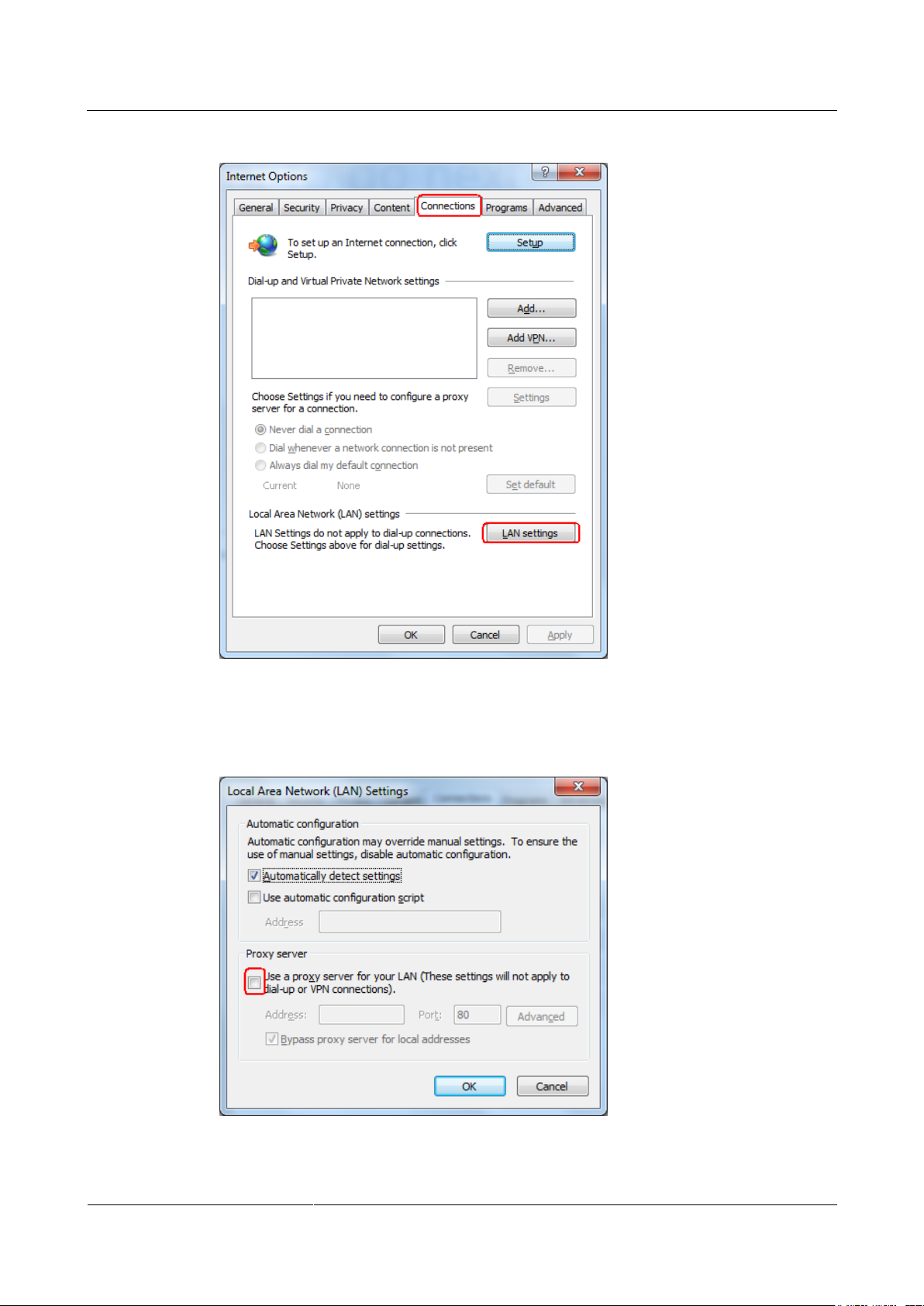
SmartLogger2000-(10-C, 11-C)
User Manual
7 WebUI
Issue Draft A (2017-02-15)
Huawei Proprietary and Confidential
Copyright © Huawei Technologies Co., Ltd.
74
Figure 7-1 LAN setting (1)
Step 4 Deselect User a proxy server for your LAN.
Figure 7-2 LAN setting (2)
Page 83
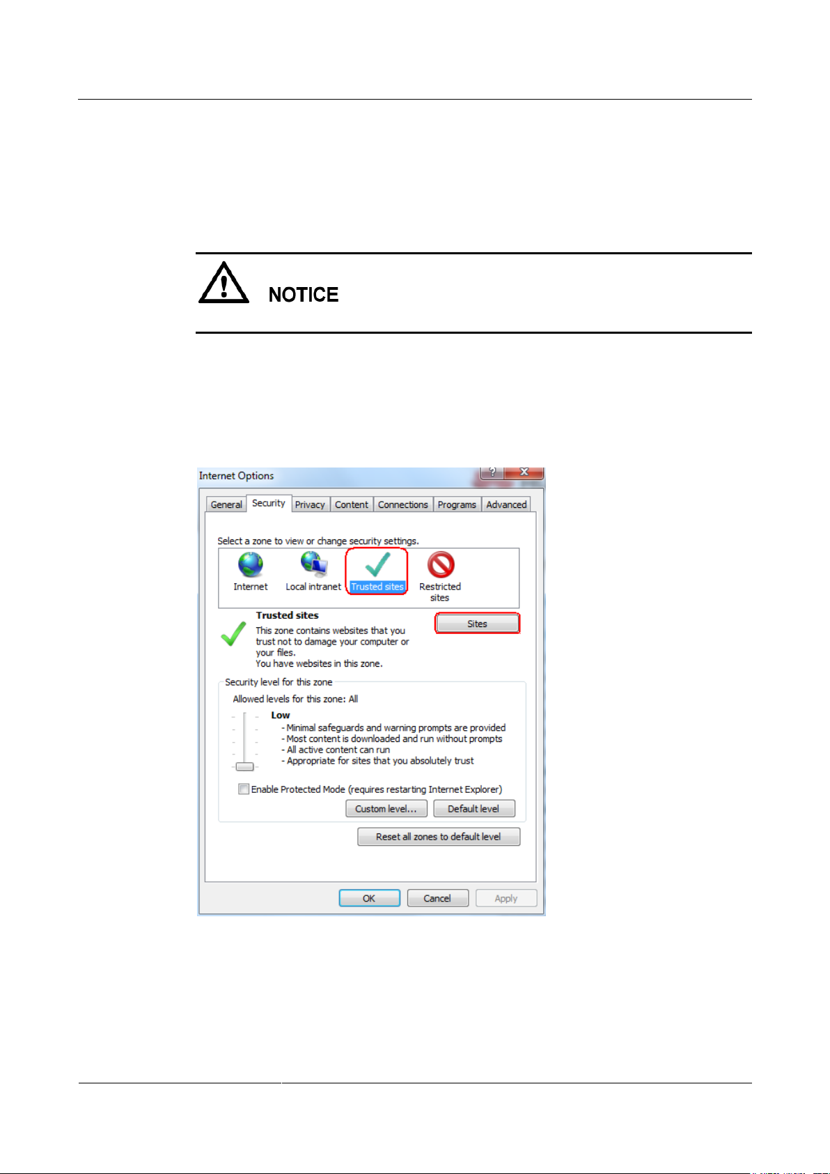
SmartLogger2000-(10-C, 11-C)
User Manual
7 WebUI
Issue Draft A (2017-02-15)
Huawei Proprietary and Confidential
Copyright © Huawei Technologies Co., Ltd.
75
Step 5 Click OK.
----End
Setting Internet Explorer Security
To export fault information and operation logs, you need to set the Internet Explorer security.
Step 1 Open Internet Explorer.
Step 2 Choose Tools > Internet Options.
Step 3 Click the Security tab and then click Sites in Trusted sites.
Figure 7-3 Internet Explorer security setting (1)
Step 4 Enter the website address of the WebUI (enter the default IP address 192.168.0.10 of the
SmartLogger for the first login), click Add, and then click Close.
Page 84
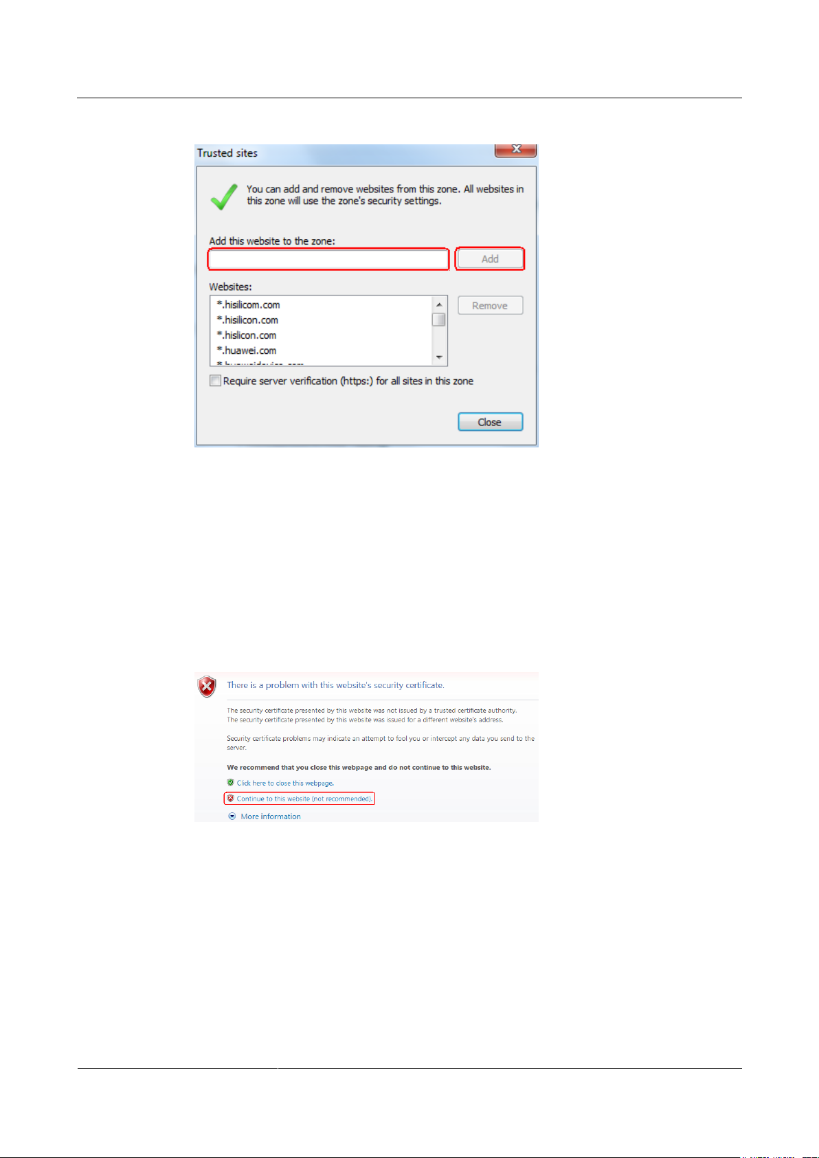
SmartLogger2000-(10-C, 11-C)
User Manual
7 WebUI
Issue Draft A (2017-02-15)
Huawei Proprietary and Confidential
Copyright © Huawei Technologies Co., Ltd.
76
Figure 7-4 Internet Explorer security setting (2)
Step 5 Set Security level for this zone to Medium or Low.
----End
Installing a Security Certificate
Step 1 If you log in to the WebUI for the first time, a message as shown in Figure 7-5 is displayed.
Click Continue to this website.
Figure 7-5 Installing a security certificate (1)
Step 2 Click Certificate Error on the right of the address bar and click View certificates.
Page 85
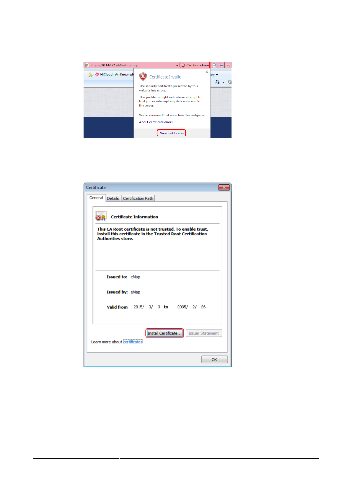
SmartLogger2000-(10-C, 11-C)
User Manual
7 WebUI
Issue Draft A (2017-02-15)
Huawei Proprietary and Confidential
Copyright © Huawei Technologies Co., Ltd.
77
Figure 7-6 Installing a security certificate (2)
Step 3 Click Install Certificate.
Figure 7-7 Installing a security certificate (3)
Step 4 Click Next.
Step 5 Click Place all certificates in the following store, and then click Browse.
Page 86
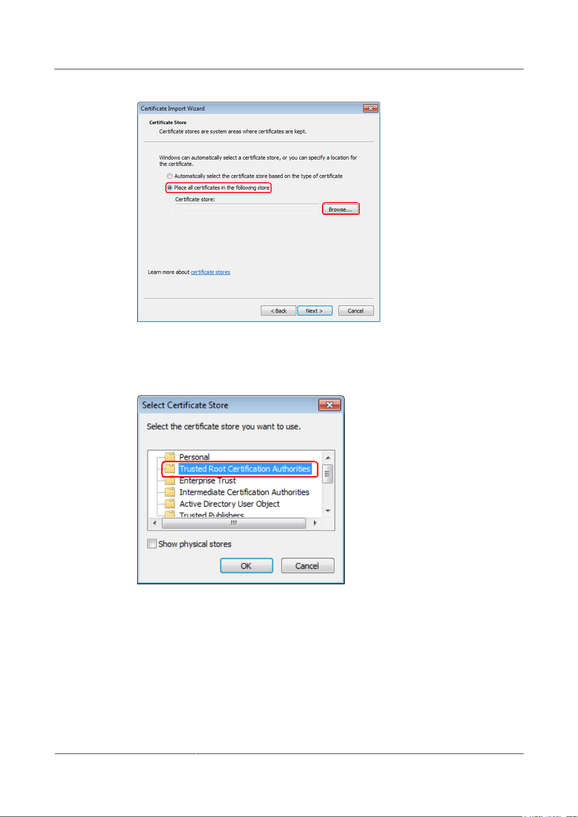
SmartLogger2000-(10-C, 11-C)
User Manual
7 WebUI
Issue Draft A (2017-02-15)
Huawei Proprietary and Confidential
Copyright © Huawei Technologies Co., Ltd.
78
Figure 7-8 Installing a security certificate (4)
Step 6 Select Trusted Root Certificate Authorities and click OK.
Figure 7-9 Installing a security certificate (5)
Step 7 Click Next.
Step 8 Click Finish. The Security Warning dialog box is displayed. Click Yes.
Page 87
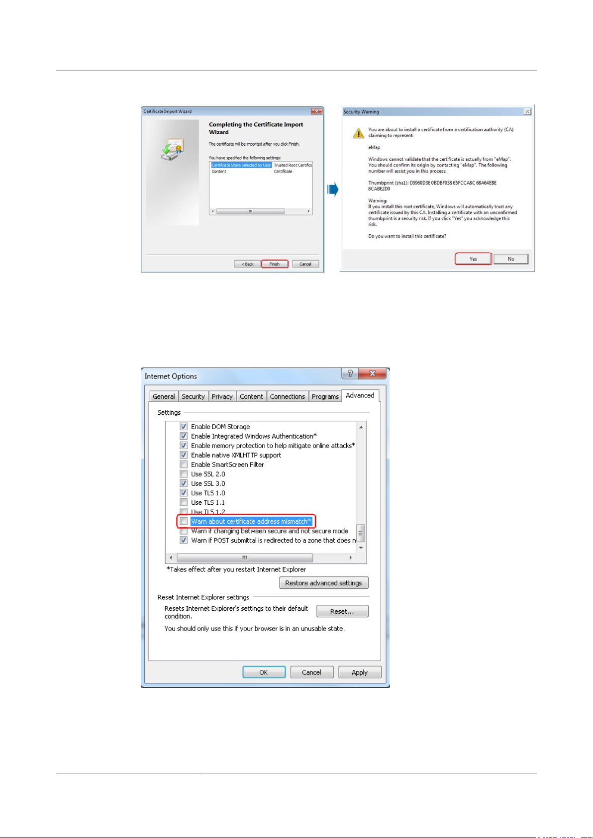
SmartLogger2000-(10-C, 11-C)
User Manual
7 WebUI
Issue Draft A (2017-02-15)
Huawei Proprietary and Confidential
Copyright © Huawei Technologies Co., Ltd.
79
Figure 7-10 Installing a security certificate (6)
Step 9 Choose Tools > Internet Options.
Step 10 Click the Advanced tab and deselect Warn about certificate address mismatch.
Figure 7-11 Installing a security certificate (7)
----End
Page 88
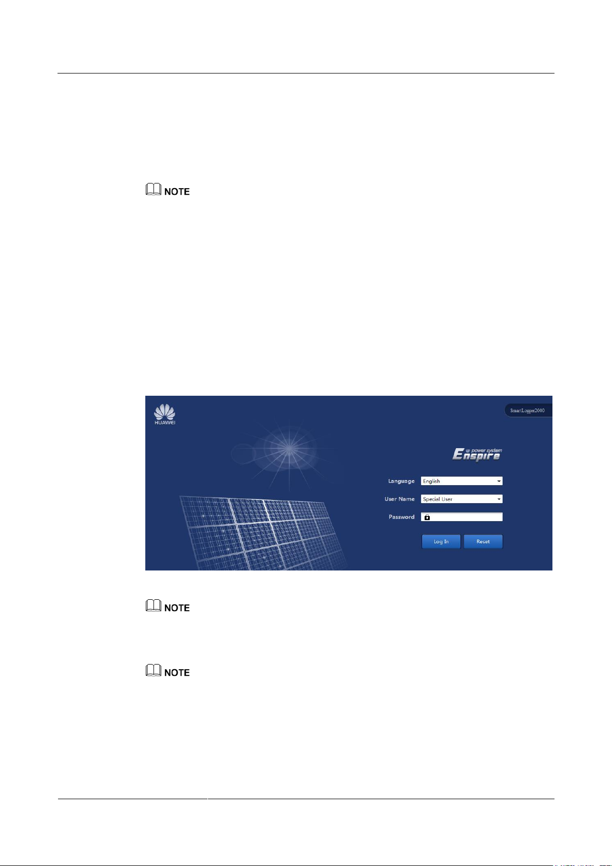
SmartLogger2000-(10-C, 11-C)
User Manual
7 WebUI
Issue Draft A (2017-02-15)
Huawei Proprietary and Confidential
Copyright © Huawei Technologies Co., Ltd.
80
7.3 Logging In to the WebUI
Context
The SmartLogger has been connected to a PC directly or over the Ethernet. For details, see
4.11 Connecting an Ethernet Network Cable.
The IP address of the SmartLogger can be obtained as follows:
When logging in to the app for the first time, obtain information including IP address from
Ethernet under Quick Settings.
When logging in to the APP subsequently, choose Settings > Comm. Param > Ethernet to view the
information.
To restore the IP address to the default IP address, press and hold down the Default key for more
than 10s until the RUN indicator blinks at short intervals (0.125s on and 0.125s off) and all other
indicators are off, and then release the Default key. The operation is valid within 5 minutes.
Procedure
Step 1 Enter https://XX.XX.XX.XX in the address box of the browser, and press Enter. The login
page is displayed.
Figure 7-12 Login page
XX.XX.XX.XX is the IP address for the SmartLogger. For example, the default IP address for the
SmartLogger is https://192.168.0.10.
Step 2 Set Language, User Name, and Password, and then click Log In.
The initial password is Changeme for system users Common User, Advanced User, and Special
User.
After the first login, change the initial password immediately to ensure account security.
If you enter wrong passwords for six consecutive times in 5 minutes, your account will be locked out.
You have to try again with the account 10 minutes later.
Page 89
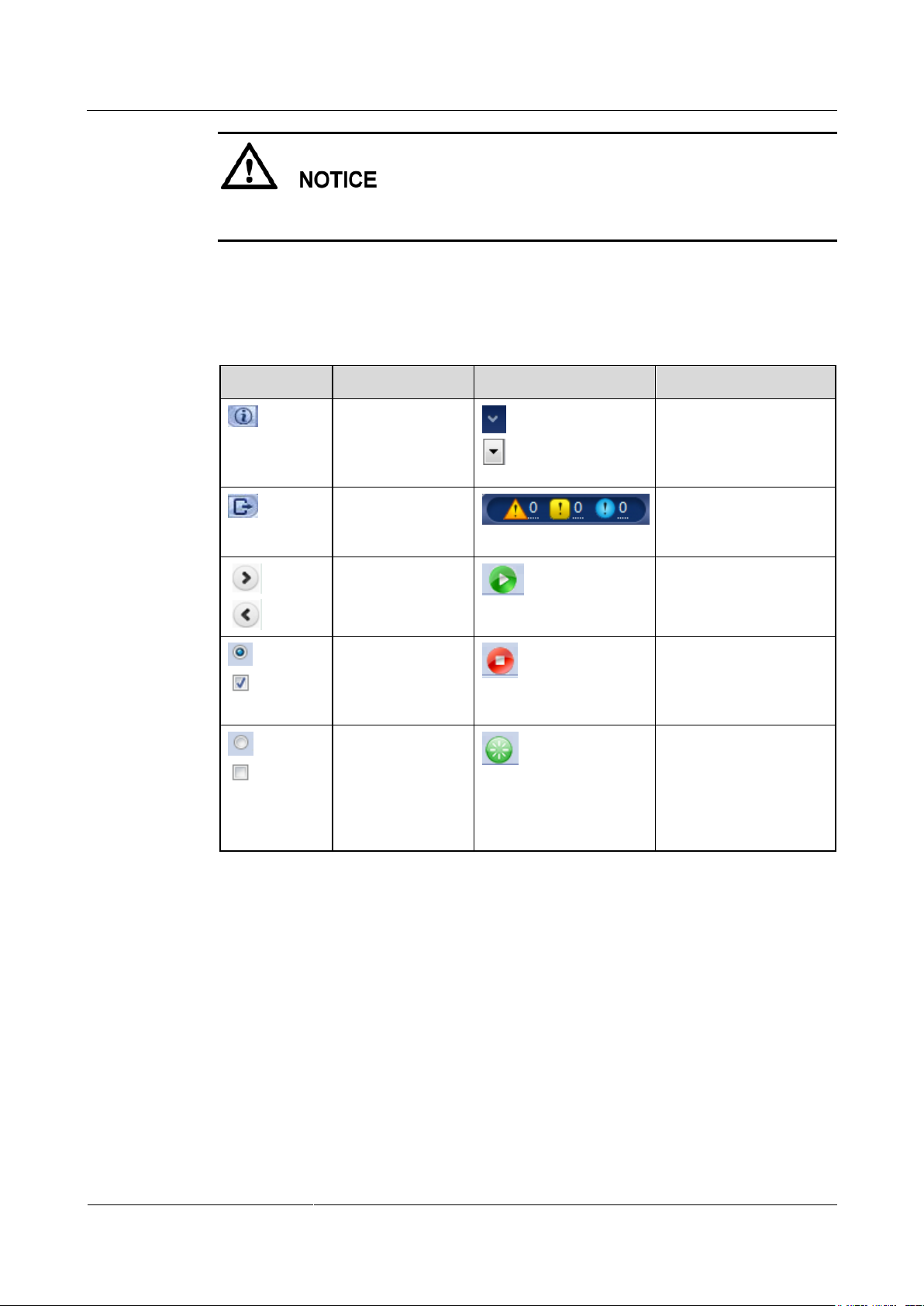
SmartLogger2000-(10-C, 11-C)
User Manual
7 WebUI
Issue Draft A (2017-02-15)
Huawei Proprietary and Confidential
Copyright © Huawei Technologies Co., Ltd.
81
If any page is blank or a menu cannot be accessed after you log in to the WebUI, clear the
Icon
Description
Icon
Description
Click the About
icon to query the
WebUI version
information.
Click the Drop-down
icon to select a
parameter or time.
Click the Exit icon
to log out.
Click the Alarm icon to
query major, minor, and
warning alarms.
Click the
Increase/Decrease
icon to adjust time.
Click the Start icon to
start the device.
The Select icon
indicates that a
parameter is
selected.
Click the Stop icon to
shut down the device.
The Select icon
indicates that a
parameter is not
selected. Click the
icon to select a
parameter.
Click the Reset icon to
reset the device.
cache, refresh the page, or log in again.
----End
7.4 Icon Description
Page 90
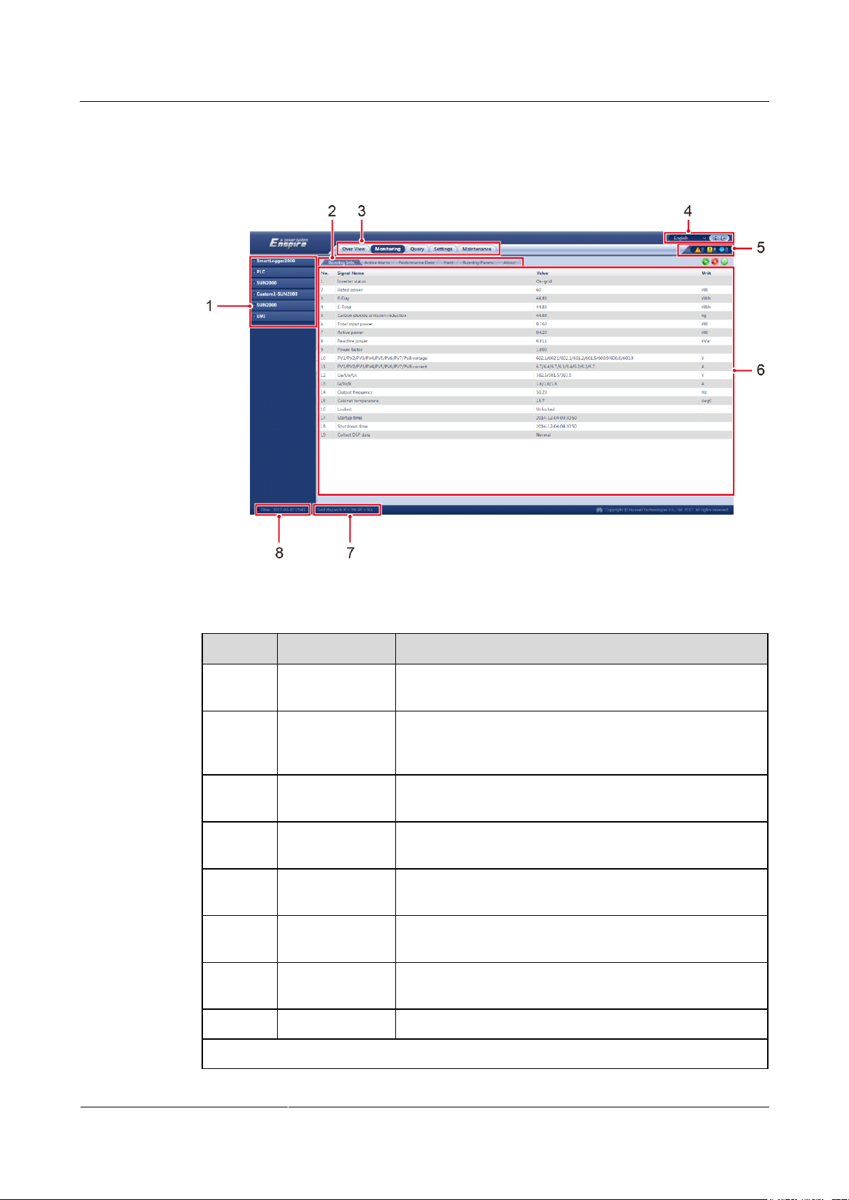
SmartLogger2000-(10-C, 11-C)
User Manual
7 WebUI
Issue Draft A (2017-02-15)
Huawei Proprietary and Confidential
Copyright © Huawei Technologies Co., Ltd.
82
7.5 WebUI Layout
No.
Function
Description
1
Secondary
navigation menu
Under the primary menu, choose a secondary menu to
select the device to be queried or the parameter to be set.
2
Tertiary
navigation
menua
Under the secondary menu, choose a tertiary menu to
access the query or setting screen.
3
Primary
navigation menu
Click the corresponding primary menu before you perform
any operation over the WebUI.
4
Display
language
Select the display language or choose to log out.
5
Alarm icon
Displays the severities and number of alarms in the system.
You can access the alarm page by clicking the number.
6
Details page
Displays the details of the queried information or
parameter settings.
7
Power grid
scheduling status
Displays the current power grid scheduling mode of the
system.
8
System time
Displays the current system time.
a: There are no tertiary navigation menus under certain secondary navigation menus.
Figure 7-13 WebUI layout
Table 7-1 WebUI layout description
Page 91
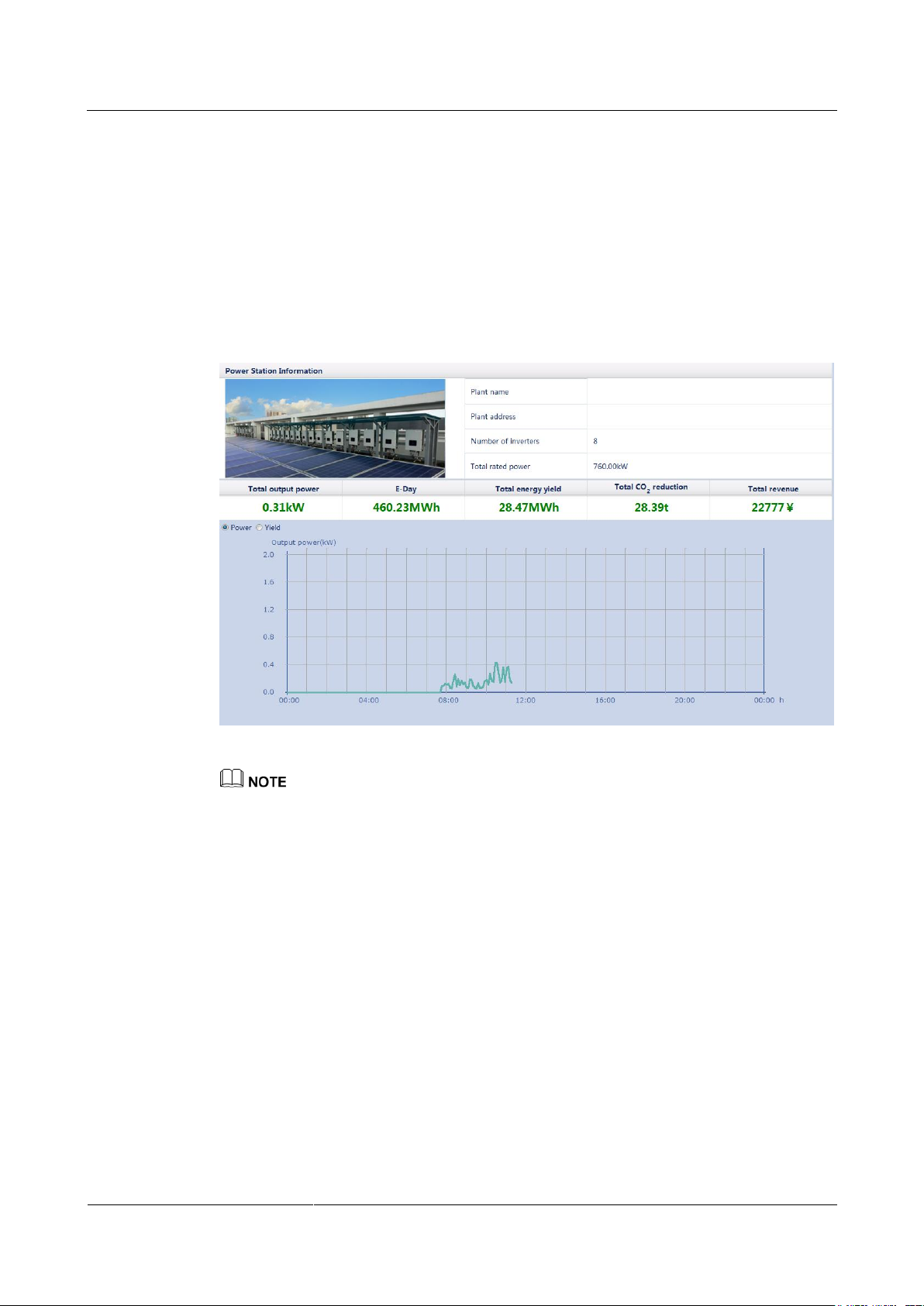
SmartLogger2000-(10-C, 11-C)
User Manual
7 WebUI
Issue Draft A (2017-02-15)
Huawei Proprietary and Confidential
Copyright © Huawei Technologies Co., Ltd.
83
7.6 Overview
7.6.1 Plant Running Information
Choose Over View > Plant Running Info. and query information on the displayed page.
Figure 7-14 Plant running information
The PV plant running information contains only the information about all the Huawei SUN2000s
connected to the SmartLogger.
7.6.2 Active Alarm
Choose Over View > Active Alarm and query alarms on the displayed page.
Page 92
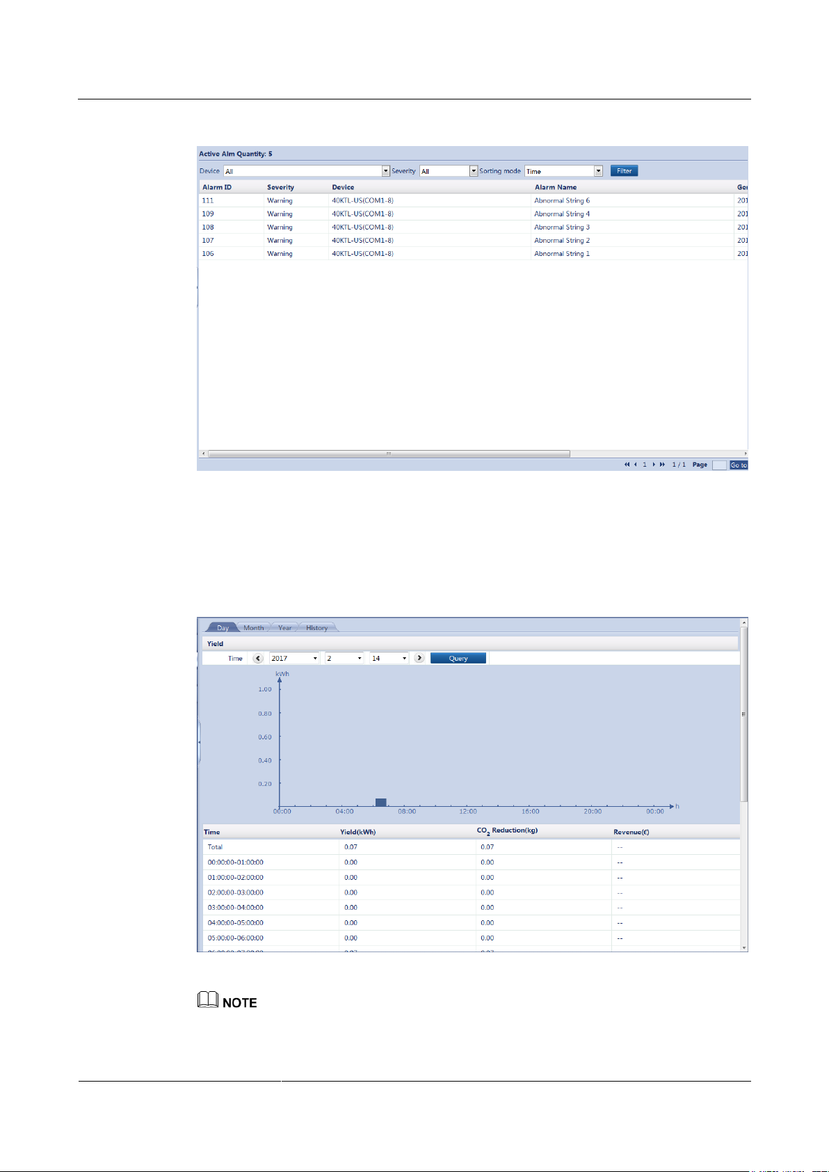
SmartLogger2000-(10-C, 11-C)
User Manual
7 WebUI
Issue Draft A (2017-02-15)
Huawei Proprietary and Confidential
Copyright © Huawei Technologies Co., Ltd.
84
Figure 7-15 Active alarm
7.6.3 Plant Yield
Choose Over View > Plant Yield and query energy yield data on the displayed page.
Figure 7-16 Plant yield
You can click a tab on the tertiary navigation menu to query the energy yield data of the specified
period.
Page 93
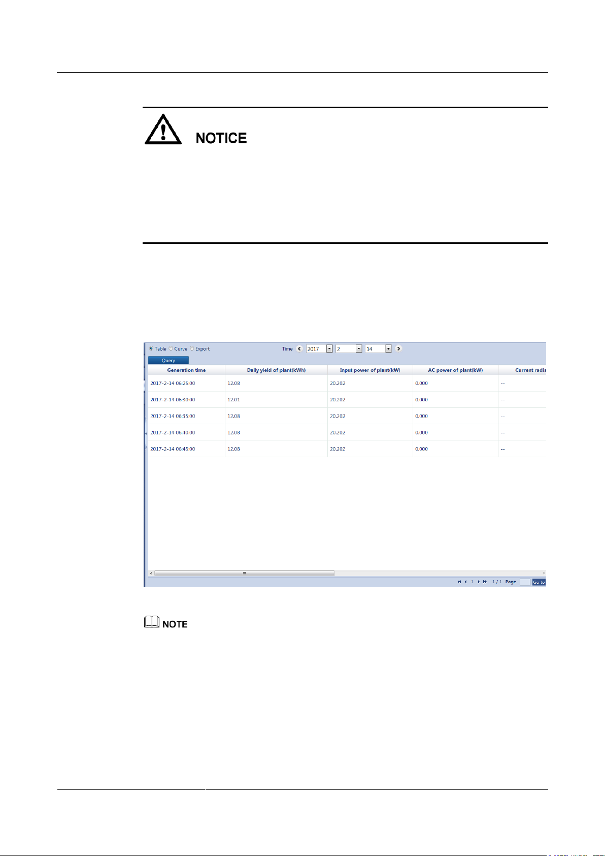
SmartLogger2000-(10-C, 11-C)
User Manual
7 WebUI
Issue Draft A (2017-02-15)
Huawei Proprietary and Confidential
Copyright © Huawei Technologies Co., Ltd.
85
The plant yield data displayed on the SmartLogger depends on the number of connected
SUN2000s.
Daily energy yield: Data of a maximum of 150 SUN2000s can be stored for one year.
Monthly energy yield: Data of a maximum of 150 SUN2000s can be stored for 10 years.
Yearly energy yield: Data of a maximum of 150 SUN2000s can be stored for 10 years.
Historical energy yield: Data of a maximum of 150 SUN2000s can be stored for 10 years.
7.6.4 Performance Data
Choose Over View > Performance Data and query related information on the displayed
page.
Figure 7-17 Performance data
You can click an option in the upper left corner of the page to display the data in the specified format
or export the data.
When changing the name of the exported file after data is exported, retain the extension .tar.gz.
Otherwise, the file will be unusable.
7.6.5 Device Running Information
Choose Over View > Device Running Info. and query device running information on the
displayed page.
Page 94
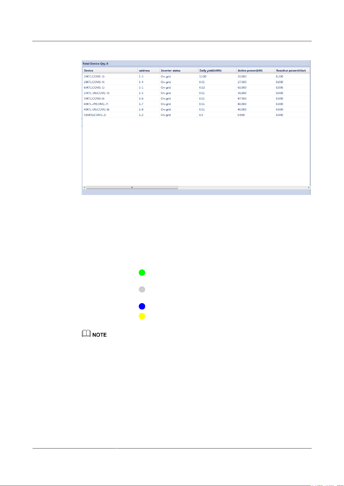
SmartLogger2000-(10-C, 11-C)
User Manual
7 WebUI
Issue Draft A (2017-02-15)
Huawei Proprietary and Confidential
Copyright © Huawei Technologies Co., Ltd.
86
Figure 7-18 Device running information
7.7 Device Monitoring
7.7.1 Querying Device Status
The indicator in front of the device name indicates the current status of a device.
If the indicator is , the SUN2000 is in the On-grid state, and the EMI, power meter,
slave SmartLogger, PLC module, or PID module is in the Online state.
If the indicator is , the SUN2000, EMI, power meter, slave SmartLogger, PLC
module, or PID module is in the Disconnection state.
If the indicator is , the SUN2000 is in the Loading state.
If the indicator is , the SUN2000 is in the Initializing, Power-Off, Idle, or any other
state in which it does not feed power to the power grid.
If a device is in the Disconnection state, its parameters cannot be set.
7.7.2 SmartLogger
7.7.2.1 Querying Master SmartLogger-Related Information
Choose Monitoring > Logger(Local) and query master SmartLogger-related information on
the displayed page.
Page 95
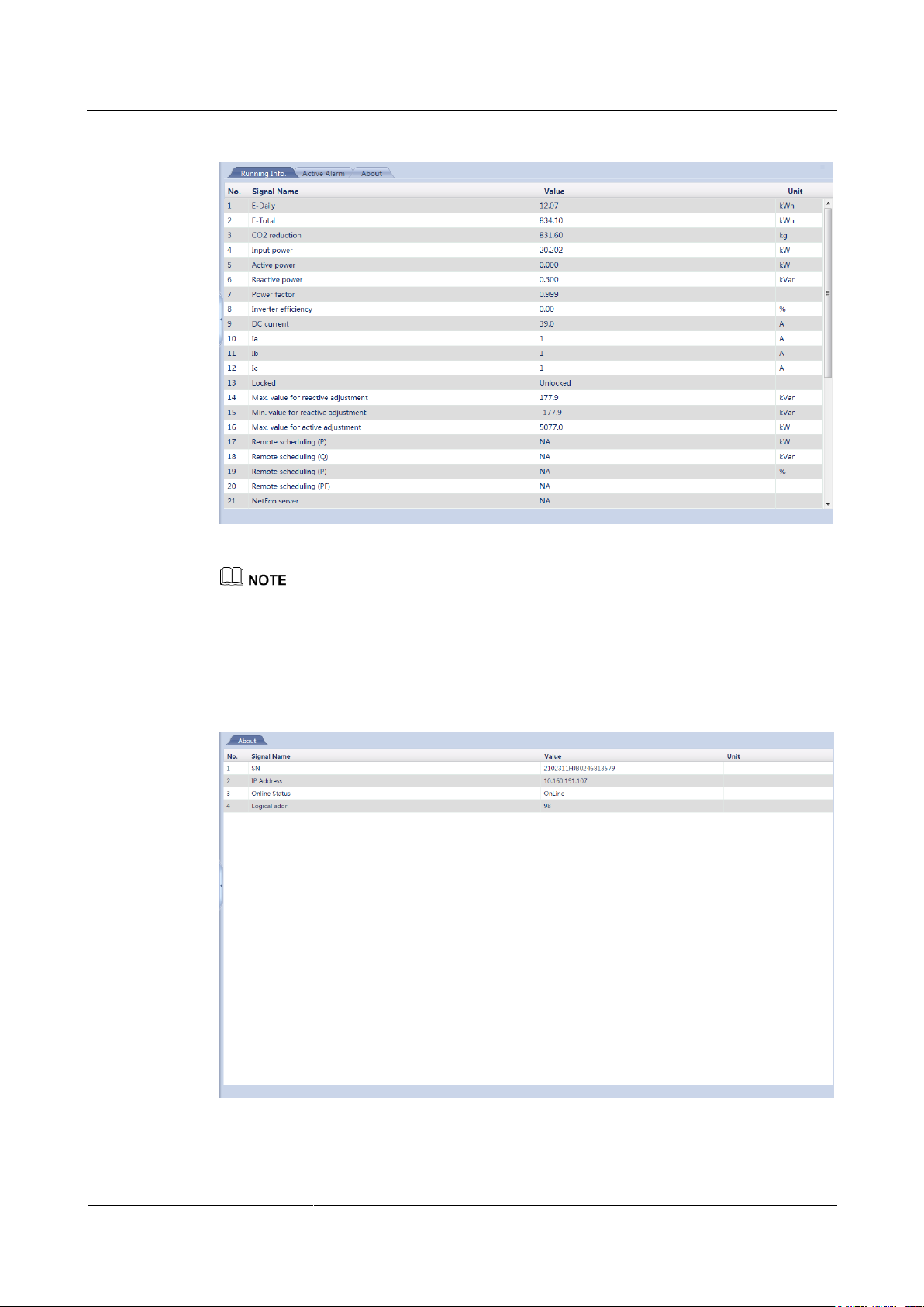
SmartLogger2000-(10-C, 11-C)
User Manual
7 WebUI
Issue Draft A (2017-02-15)
Huawei Proprietary and Confidential
Copyright © Huawei Technologies Co., Ltd.
87
Figure 7-19 Querying master SmartLogger-related information
You can click a tab on the tertiary navigation menu to query master SmartLogger-related information.
7.7.2.2 Querying Slave SmartLogger-Related Information
Select a slave SmartLogger on the Monitoring tab page to query its information.
Figure 7-20 Querying slave SmartLogger-related information
Page 96
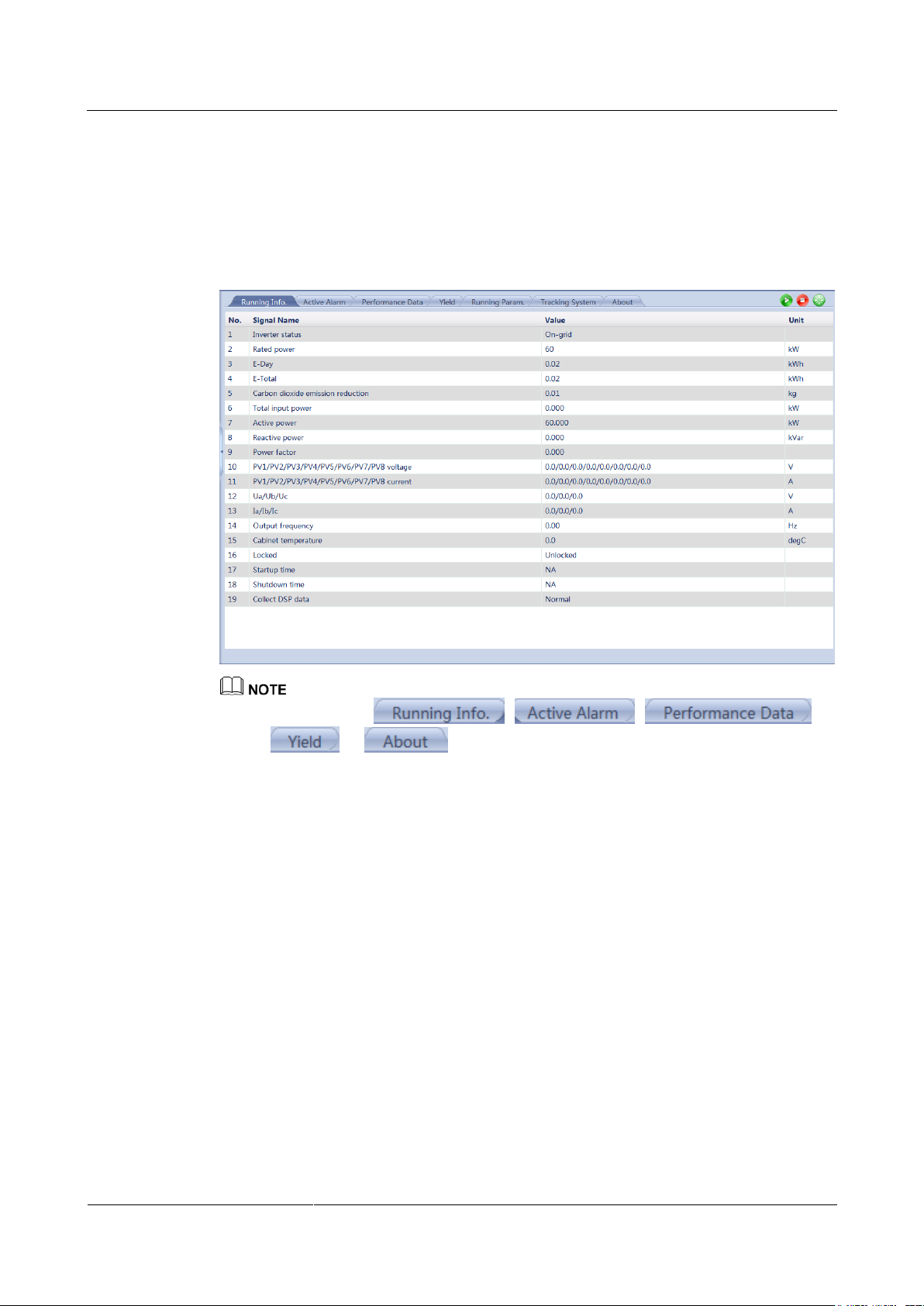
SmartLogger2000-(10-C, 11-C)
User Manual
7 WebUI
Issue Draft A (2017-02-15)
Huawei Proprietary and Confidential
Copyright © Huawei Technologies Co., Ltd.
88
7.7.3 SUN2000
7.7.3.1 Querying Related Information
Choose Monitoring > SUN2000 and query related information on the displayed page.
Figure 7-21 Querying SUN2000-related information
You can click the , , ,
or tab on the tertiary navigation menu to query SUN2000-related
information.
You can click the Start, Stop, or Reset icon to send the corresponding command to the SUN2000.
The login password is required if you need to send a command.
7.7.3.2 Setting Running Parameters (Advanced User)
Settings Page
Because of permission restriction, log in to the WebUI as an advanced user. Choose
Monitoring > SUN2000 > Running Param. to access the setting page.
Page 97
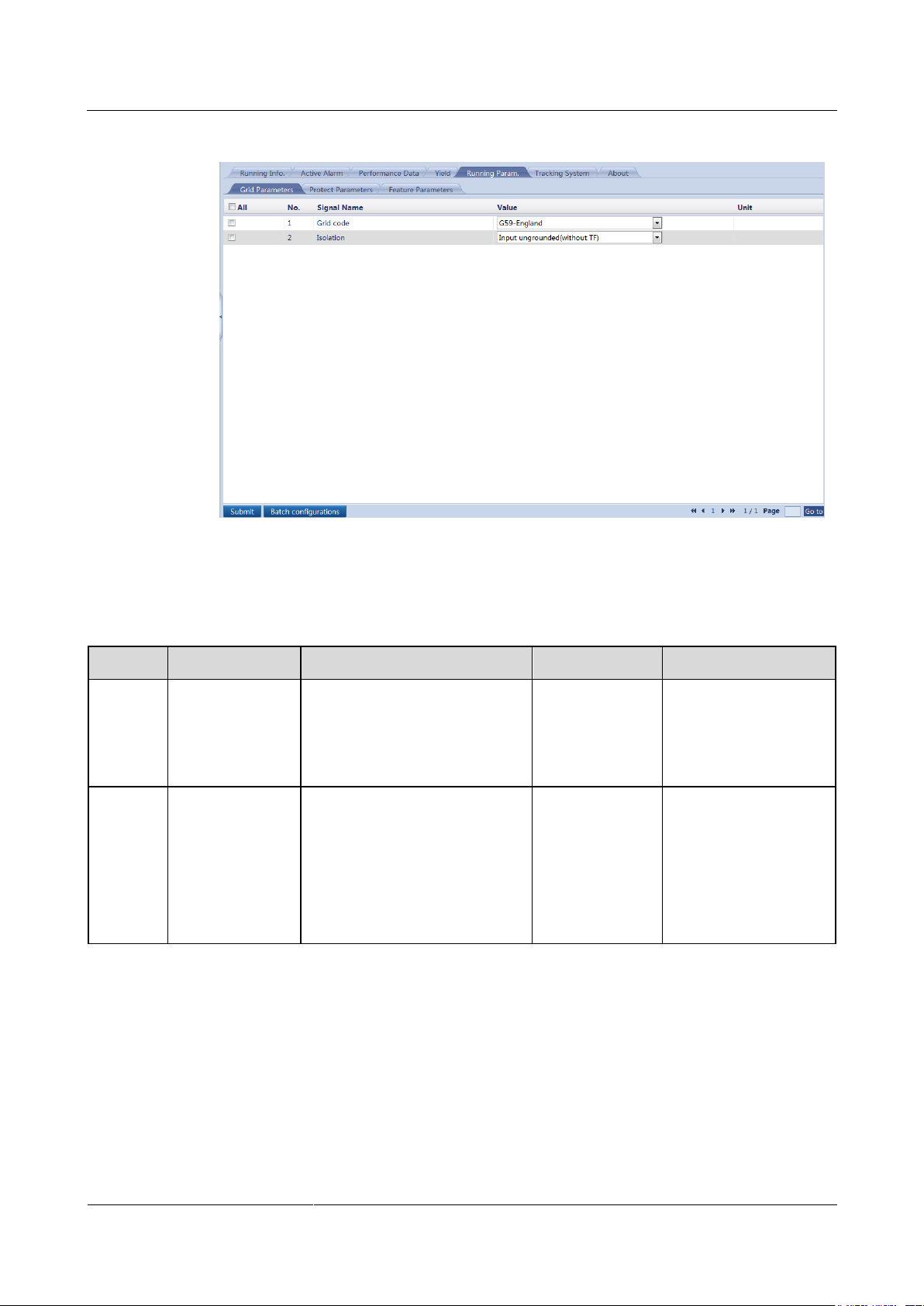
SmartLogger2000-(10-C, 11-C)
User Manual
7 WebUI
Issue Draft A (2017-02-15)
Huawei Proprietary and Confidential
Copyright © Huawei Technologies Co., Ltd.
89
Figure 7-22 Running Param. (advanced user)
No.
Parameter
Description
Default Value
Value Range
1
Grid code
Set this parameter based on the
grid code of the country or
region where the SUN2000 is
used and the SUN2000
application scenario.
The default
value varies with
the model. The
displayed value
prevails.
N/A
2
Isolation
Specifies the SUN2000 working
mode based on the grounding
status at the DC side and the
connection to the power grid.
The default
value varies
depending on the
grid code. The
displayed value
prevails.
Input grounded
(with a transformer)
Input ungrounded
(with no
transformer)
Input ungrounded
(with a transformer)
Grid Parameters
Table 7-2 Parameter description
Page 98
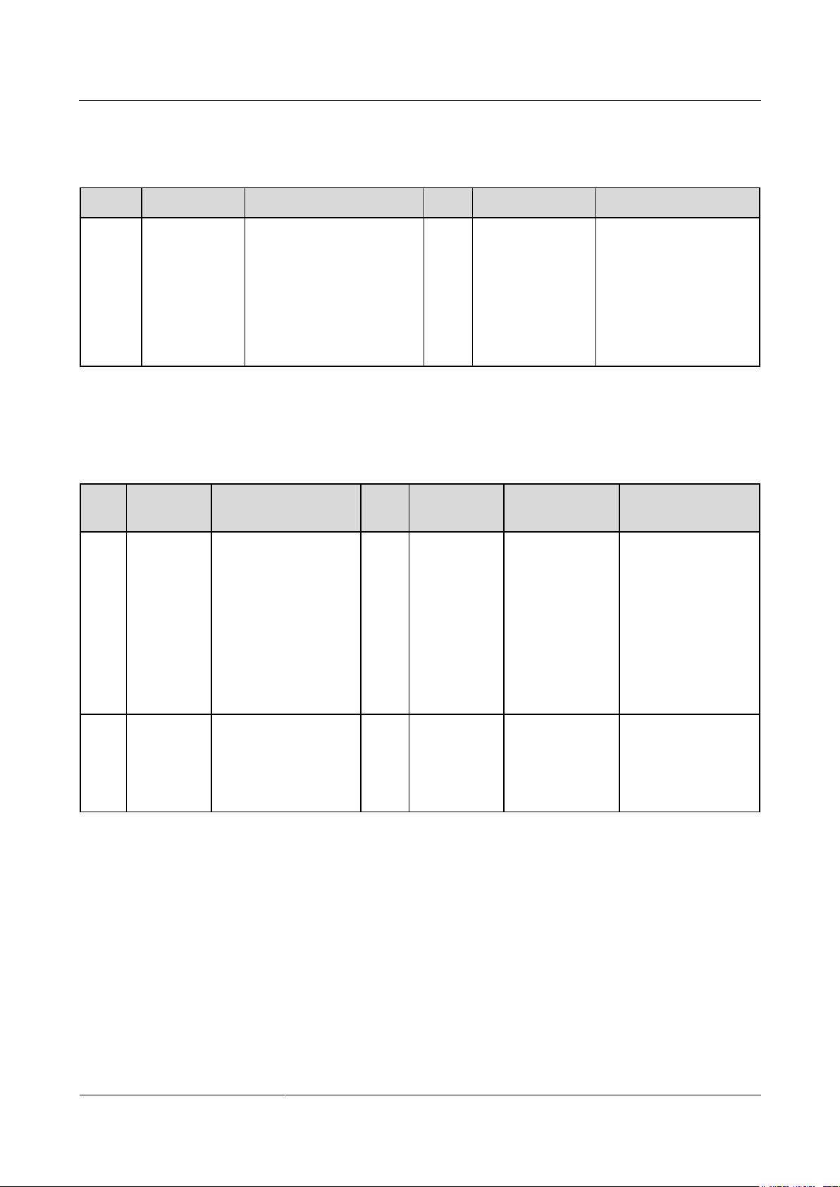
SmartLogger2000-(10-C, 11-C)
User Manual
7 WebUI
Issue Draft A (2017-02-15)
Huawei Proprietary and Confidential
Copyright © Huawei Technologies Co., Ltd.
90
Protection Parameters
No.
Parameter
Description
Unit
Default Value
Value Range
1
Insulation
resistance
protection
To ensure device safety,
the SUN2000 detects the
insulation resistance of the
input side to the ground
when it starts a self-check.
If the detected value is less
than the preset value, the
SUN2000 does not start.
MΩ
The default value
for a 1000 V
SUN2000 is 0.1,
and the default
value for 1100 V
and 1500 V
SUN2000s is
0.05.
The value range for a
1000 V SUN2000 is
[0.033, 1], and the value
range for 1100 V and
1500 V SUN2000s is
[0.033, 1.5].
No.
Parameter
Description
Unit
Default
Value
Value Range
Remarks
1
MPPT
multi-peak
scanning
When the SUN2000 is
used in scenarios
where PV strings are
obviously shaded,
enable this function.
Then the SUN2000
will perform MPPT
scanning at regular
intervals to locate the
maximum power.
N/A
Disable
Disable
Enable
The scanning
interval is set by
MPPT multi-peak
scanning interval.
2
MPPT
multi-peak
scanning
interval
Specifies the MPPT
multi-peak scanning
interval.
min
15
[5, 30]
This parameter is
displayed only when
MPPT multi-peak
scanning is set to
Enable.
Table 7-3 Parameter description
Feature Parameters
Table 7-4 Parameter description
Page 99

SmartLogger2000-(10-C, 11-C)
User Manual
7 WebUI
Issue Draft A (2017-02-15)
Huawei Proprietary and Confidential
Copyright © Huawei Technologies Co., Ltd.
91
No.
Parameter
Description
Unit
Default
Value
Value Range
Remarks
3
RCD
enhancing
RCD refers to the
residual current of the
SUN2000 to the
ground. To ensure
device security and
personal safety, RCD
should comply with
the standard. If an AC
switch with a residual
current detection
function is installed
outside the SUN2000,
this function should
be enabled to reduce
the residual current
generated during
SUN2000 running,
thereby preventing the
AC switch from
misoperations.
N/A
Disable
Disable
Enable
N/A
4
Reactive
power
output at
night
In some specific
application scenarios,
a power grid company
requires that the
SUN2000 can
perform reactive
power compensation
at night to ensure that
the power factor of
the local power grid
meets requirements.
N/A
Disable
Disable
Enable
This parameter is
configurable only
when Isolation is set
to Input
ungrounded (with
a transformer).
5
Strong
adaptabilit
y
If the value of power
grid short circuit
capacity/power plant
installed capacity is
less than 3 and the
power grid impedance
exceeds the upper
threshold, the power
grid quality will be
affected and the
SUN2000 may be
unable to run
properly. Set Strong
adaptability to
Enable.
N/A
Disable
Disable
Enable
N/A
Page 100

SmartLogger2000-(10-C, 11-C)
User Manual
7 WebUI
Issue Draft A (2017-02-15)
Huawei Proprietary and Confidential
Copyright © Huawei Technologies Co., Ltd.
92
No.
Parameter
Description
Unit
Default
Value
Value Range
Remarks
6
Power
quality
optimizatio
n mode
When the power grid
is in strong
adaptability mode, set
Power quality
optimization mode to
Enable to optimize
the output current
harmonic of the
SUN2000.
N/A
Disable
Disable
Enable
N/A
7
PV module
type
Specifies the type of
PV modules.
N/A
Crystalline
silicon
Crystalline
silicon
Film
CPV 1
CPV 2
If PV module
type is set to
Crystalline
silicon or Film,
the SUN2000
will run properly
and will not shut
down if PV
modules are
shaded.
If PV module
type is set to
CPV 1, the
SUN2000 can
restart quickly in
60 minutes if PV
modules are
shaded and the
input power
greatly
decreases.
If PV module
type is set to
CPV 2, the
SUN2000 can
restart quickly in
10 minutes if PV
modules are
shaded and the
input power
greatly
decreases.
 Loading...