

Huawei S6700-48-EI, S6720-30C-EI-24S-AC, S6720-54C-EI-48S-AC, S6700-EI, S6700-24-EI Hardware Description
...Page 1
S6700 Series Ethernet Switches
Hardware Description
Issue 12
Date 2015-07-31
HUAWEI TECHNOLOGIES CO., LTD.
Page 2

Copyright © Huawei Technologies Co., Ltd. 2015. All rights reserved.
No part of this document may be reproduced or transmitted in any form or by any means without prior written
consent of Huawei Technologies Co., Ltd.
Trademarks and Permissions
and other Huawei trademarks are trademarks of Huawei Technologies Co., Ltd.
All other trademarks and trade names mentioned in this document are the property of their respective holders.
Notice
The purchased products, services and features are stipulated by the contract made between Huawei and the
customer. All or part of the products, services and features described in this document may not be within the
purchase scope or the usage scope. Unless otherwise specified in the contract, all statements, information,
and recommendations in this document are provided "AS IS" without warranties, guarantees or representations
of any kind, either express or implied.
The information in this document is subject to change without notice. Every effort has been made in the
preparation of this document to ensure accuracy of the contents, but all statements, information, and
recommendations in this document do not constitute a warranty of any kind, express or implied.
Huawei Technologies Co., Ltd.
Address: Huawei Industrial Base
Bantian, Longgang
Shenzhen 518129
People's Republic of China
Website: http://e.huawei.com
Issue 12 (2015-07-31) Huawei Proprietary and Confidential
Copyright © Huawei Technologies Co., Ltd.
i
Page 3
S6700 Series Ethernet Switches
Hardware Description About This Document
About This Document
Intended Audience
This document provides an overall description of the S6700 hardware, helping you obtain
detailed information about each chassis, card, power module, fan module, cable, and optical
module.
This document is intended for:
l Network planning engineers
l Hardware installation engineers
l Commissioning engineers
l On-site maintenance engineers
l System maintenance engineers
Symbol Conventions
The symbols that may be found in this document are defined as follows.
Symbol Description
Indicates an imminently hazardous situation
which, if not avoided, will result in death or
serious injury.
Indicates a potentially hazardous situation
which, if not avoided, could result in death or
serious injury.
Indicates a potentially hazardous situation
which, if not avoided, may result in minor or
moderate injury.
Indicates a potentially hazardous situation
which, if not avoided, could result in
equipment damage, data loss, performance
deterioration, or unanticipated results.
NOTICE is used to address practices not
related to personal injury.
Issue 12 (2015-07-31) Huawei Proprietary and Confidential
Copyright © Huawei Technologies Co., Ltd.
ii
Page 4
NOTE
S6700 Series Ethernet Switches
Hardware Description
Symbol Description
Command Conventions
The command conventions that may be found in this document are defined as follows.
Convention Description
Boldface The keywords of a command line are in boldface.
Italic Command arguments are in italics.
About This Document
Calls attention to important information, best
practices and tips.
NOTE is used to address information not
related to personal injury, equipment damage,
and environment deterioration.
Declaration
This manual is only a reference for you to configure your devices. The contents in the manual,
such as web pages, command line syntax, and command outputs, are based on the device
conditions in the lab. The manual provides instructions for general scenarios, but do not cover
all usage scenarios of all product models. The contents in the manual may be different from your
actual device situations due to the differences in software versions, models, and configuration
files. The manual will not list every possible difference. You should configure your devices
according to actual situations.
[ ] Items (keywords or arguments) in brackets [ ] are optional.
{ x | y | ... } Optional items are grouped in braces and separated by
vertical bars. One item is selected.
[ x | y | ... ] Optional items are grouped in brackets and separated by
vertical bars. One item is selected or no item is selected.
{ x | y | ... }
[ x | y | ... ]
&<1-n> The parameter before the & sign can be repeated 1 to n times.
# A line starting with the # sign is comments.
*
*
Optional items are grouped in braces and separated by
vertical bars. A minimum of one item or a maximum of all
items can be selected.
Optional items are grouped in brackets and separated by
vertical bars. Several items or no item can be selected.
The specifications provided in this manual are tested in lab environment (for example, the tested
device has been installed with a certain type of boards or only one protocol is run on the device).
Issue 12 (2015-07-31) Huawei Proprietary and Confidential
Copyright © Huawei Technologies Co., Ltd.
iii
Page 5

S6700 Series Ethernet Switches
Hardware Description
Results may differ from the listed specifications when you attempt to obtain the maximum values
with multiple functions enabled on the device.
Change History
Changes between document issues are cumulative. The latest document issue contains all
changes made to previous issues.
Changes in Issue 12 (2015-07-31)
This version has the following updates:
The documentation is modified according to updates in product features.
Changes in Issue 11 (2015-07-17)
This version has the following updates:
About This Document
The documentation is modified according to updates in product features.
Changes in Issue 10 (2015-01-15)
This version has the following updates:
The following information is added:
l 1.8 Components Available in V200R005C02 Version
The following information is modified:
l 2.4.2 Appearance and Structure
l 6.8 Copper Cable
Changes in Issue 09 (2014-06-30)
This version has the following updates:
The following information is added:
l 1.7 Components Available in V200R005C01 Version
Changes in Issue 08 (2014-03-20)
This version has the following updates:
The documentation is modified according to updates in product features.
Changes in Issue 07 (2013-11-06)
This version has the following updates:
The following information is modified:
l 2.4.3 Indicator Description
Issue 12 (2015-07-31) Huawei Proprietary and Confidential
Copyright © Huawei Technologies Co., Ltd.
iv
Page 6

S6700 Series Ethernet Switches
Hardware Description About This Document
Changes in Issue 06 (2013-09-30)
This version has the following updates:
The following information is modified:
l 2.2 Naming Conventions
l 6.8 Copper Cable
Changes in Issue 05 (2013-07-25)
This version has the following updates:
The following information is modified:
l 7 Pluggable Modules for Interfaces
Changes in Issue 04 (2013-05-30)
This version has the following updates:
The documentation is modified according to updates in V200R003C00.
Changes in Issue 03 (2013-04-20)
This version has the following updates:
The following information is modified:
l 6 Cables
Changes in Issue 02 (2013-02-08)
This version has the following updates:
The documentation is modified according to updates in product features.
Changes in Issue 01 (2012-12-08)
Initial commercial release.
Issue 12 (2015-07-31) Huawei Proprietary and Confidential
Copyright © Huawei Technologies Co., Ltd.
v
Page 7

S6700 Series Ethernet Switches
Hardware Description
Contents
Contents
About This Document.....................................................................................................................ii
1 Version Support for Components..............................................................................................1
1.1 Components Available in V100R006C00 Version........................................................................................................2
1.2 Components Available in V200R001C00 Version........................................................................................................2
1.3 Components Available in V200R001C01 Version........................................................................................................3
1.4 Components Available in V200R002C00 Version........................................................................................................3
1.5 Components Available in V200R003C00 Version........................................................................................................4
1.6 Components Available in V200R005C00 Version........................................................................................................5
1.7 Components Available in V200R005C01 Version........................................................................................................5
1.8 Components Available in V200R005C02 Version........................................................................................................6
1.9 Components Available in V200R008C00 Version........................................................................................................7
2 Chassis.............................................................................................................................................9
2.1 Chassis Overview.........................................................................................................................................................10
2.2 Naming Conventions....................................................................................................................................................10
2.3 Port Numbering Conventions.......................................................................................................................................11
2.4 S6700-EI.......................................................................................................................................................................12
2.4.1 Version Mapping.......................................................................................................................................................12
2.4.2 Appearance and Structure..........................................................................................................................................12
2.4.3 Indicator Description.................................................................................................................................................15
2.4.4 Port Description.........................................................................................................................................................19
2.4.5 Power Supply.............................................................................................................................................................22
2.4.6 Heat Dissipation........................................................................................................................................................23
2.4.7 Specifications.............................................................................................................................................................24
2.5 S6720-EI.......................................................................................................................................................................26
2.5.1 Version Mapping.......................................................................................................................................................26
2.5.2 Appearance and Structure..........................................................................................................................................26
2.5.3 Indicator Description.................................................................................................................................................29
2.5.4 Port Description.........................................................................................................................................................36
2.5.5 Power Supply Configuration.....................................................................................................................................37
2.5.6 Heat Dissipation........................................................................................................................................................38
2.5.7 Specifications.............................................................................................................................................................39
Issue 12 (2015-07-31) Huawei Proprietary and Confidential
Copyright © Huawei Technologies Co., Ltd.
vi
Page 8

S6700 Series Ethernet Switches
Hardware Description
Contents
3 Power Modules............................................................................................................................42
3.1 350 W DC power module.............................................................................................................................................43
3.2 500 W DC Power Module............................................................................................................................................46
3.3 600 W AC Power Module............................................................................................................................................48
3.4 500 W AC Power Module............................................................................................................................................51
4 Fan Modules.................................................................................................................................54
4.1 CX7E1FANA Fan Module...........................................................................................................................................55
4.2 FAN-060B-B Fan Module............................................................................................................................................57
5 Cards..............................................................................................................................................59
5.1 Introduction..................................................................................................................................................................60
5.1.1 Card Classification....................................................................................................................................................60
5.2 ES5D21Q04Q01 (4-Port 40 Gig QSFP+ Rear Interface Card, Used in S6720-EI Series)..........................................60
5.2.1 Introduction...............................................................................................................................................................60
5.2.2 Version Mapping.......................................................................................................................................................61
5.2.3 Functions and Features..............................................................................................................................................61
5.2.4 Indicators and Ports...................................................................................................................................................61
5.2.5 Specifications.............................................................................................................................................................63
5.2.6 Ordering Information.................................................................................................................................................63
6 Cables.............................................................................................................................................64
6.1 Ground Cable................................................................................................................................................................65
6.2 Optical Fiber.................................................................................................................................................................66
6.3 Network Cable..............................................................................................................................................................73
6.4 DC Power Cable (OT and Cord End Terminals)..........................................................................................................75
6.5 DC Power Cable (Quick-Connect Cord End Terminal)...............................................................................................77
6.6 AC Power Cable...........................................................................................................................................................79
6.7 Console Cable...............................................................................................................................................................79
6.8 Copper Cable................................................................................................................................................................81
7 Pluggable Modules for Interfaces............................................................................................84
7.1 Important Notes About Using Optical Modules Certified for Huawei Switches.........................................................85
7.1.1 How to Identify Huawei-Certified Optical Modules.................................................................................................85
7.1.2 Risks of Using Non-Huawei-Certified Optical Modules..........................................................................................85
7.2 Understanding Optical Modules...................................................................................................................................86
7.2.1 What Is an Optical Module........................................................................................................................................86
7.2.2 Types of Optical Modules.........................................................................................................................................87
7.2.3 Parameter Description...............................................................................................................................................90
7.2.4 How to View Optical Module Parameters.................................................................................................................91
7.3 Understanding Copper Modules...................................................................................................................................92
7.4 Models and Parameters.................................................................................................................................................92
7.4.1 SFP/eSFP Modules....................................................................................................................................................92
7.4.2 SFP+ Modules...........................................................................................................................................................99
Issue 12 (2015-07-31) Huawei Proprietary and Confidential
Copyright © Huawei Technologies Co., Ltd.
vii
Page 9

S6700 Series Ethernet Switches
Hardware Description Contents
7.4.3 QSFP+ Modules......................................................................................................................................................103
Issue 12 (2015-07-31) Huawei Proprietary and Confidential
Copyright © Huawei Technologies Co., Ltd.
viii
Page 10

S6700 Series Ethernet Switches
Hardware Description 1 Version Support for Components
1 Version Support for Components
About This Chapter
NOTE
l The availability of device models and modules described in this document will be specified in product
change notices (PCNs). For details, contact the product manager of Huawei local office.
l The figures in this document are for reference only.
1.1 Components Available in V100R006C00 Version
1.2 Components Available in V200R001C00 Version
1.3 Components Available in V200R001C01 Version
1.4 Components Available in V200R002C00 Version
1.5 Components Available in V200R003C00 Version
1.6 Components Available in V200R005C00 Version
1.7 Components Available in V200R005C01 Version
1.8 Components Available in V200R005C02 Version
1.9 Components Available in V200R008C00 Version
Issue 12 (2015-07-31) Huawei Proprietary and Confidential
Copyright © Huawei Technologies Co., Ltd.
1
Page 11
S6700 Series Ethernet Switches
Hardware Description
1 Version Support for Components
1.1 Components Available in V100R006C00 Version
NOTE
Components marked with * are added in V100R006C00.
Available Models
Table 1-1 S6700 switch models available in V100R006C00
Series Model Maximum Number of Service Ports
S6700-EI
S6700-24-EI
S6700-48-EI
*
*
24 total:
24 10GE SFP+ optical ports (10GE/GE auto-sensing)
48 total:
48 10GE SFP+ optical ports (10GE/GE auto-sensing)
Available Power Modules
Table 1-2 S6700 power modules available in V100R006C00
Power
Module
Type
AC power
module
Power Module Power Description
W0PSA5000 500 W AC power module
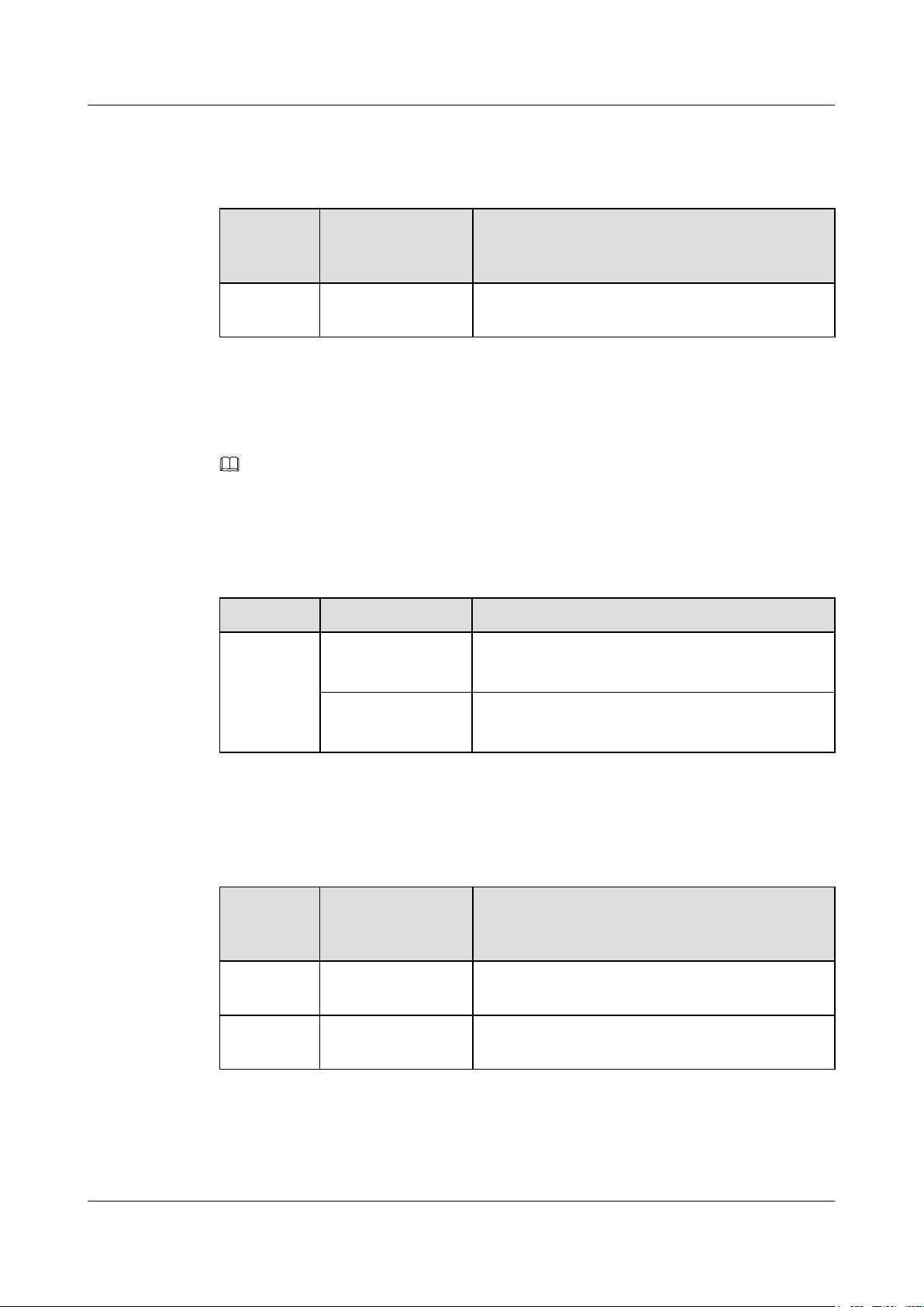
1.2 Components Available in V200R001C00 Version
Available Models
Table 1-3 S6700 switch models available in V200R001C00
Series Model Maximum Number of Service Ports
S6700-EI S6700-24-EI 24 total:
24 10GE SFP+ optical ports (10GE/GE auto-sensing)
S6700-48-EI 48 total:
48 10GE SFP+ optical ports (10GE/GE auto-sensing)
Issue 12 (2015-07-31) Huawei Proprietary and Confidential
Copyright © Huawei Technologies Co., Ltd.
2
Page 12
S6700 Series Ethernet Switches
Hardware Description
Available Power Modules
Table 1-4 S6700 power modules available in V200R001C00
1 Version Support for Components
Power
Module
Type
AC power
module
Power Module Power Description
W0PSA5000 500 W AC power module
1.3 Components Available in V200R001C01 Version
NOTE
Components marked with * are added in V200R001C01.
Available Models
Table 1-5 S6700 switch models available in V200R001C01
Series Model Maximum Number of Service Ports
S6700-EI S6700-24-EI 24 total:
24 10GE SFP+ optical ports (10GE/GE auto-sensing)
S6700-48-EI 48 total:
48 10GE SFP+ optical ports (10GE/GE auto-sensing)
Available Power Modules
Table 1-6 S6700 power modules available in V200R001C01
Power
Module
Type
AC power
module
DC power
module
Power Module Power Description
W0PSA5000 500 W AC power module
*
LS6W2PSD0500
500 W DC power module
1.4 Components Available in V200R002C00 Version
Issue 12 (2015-07-31) Huawei Proprietary and Confidential
Copyright © Huawei Technologies Co., Ltd.
3
Page 13
S6700 Series Ethernet Switches
Hardware Description
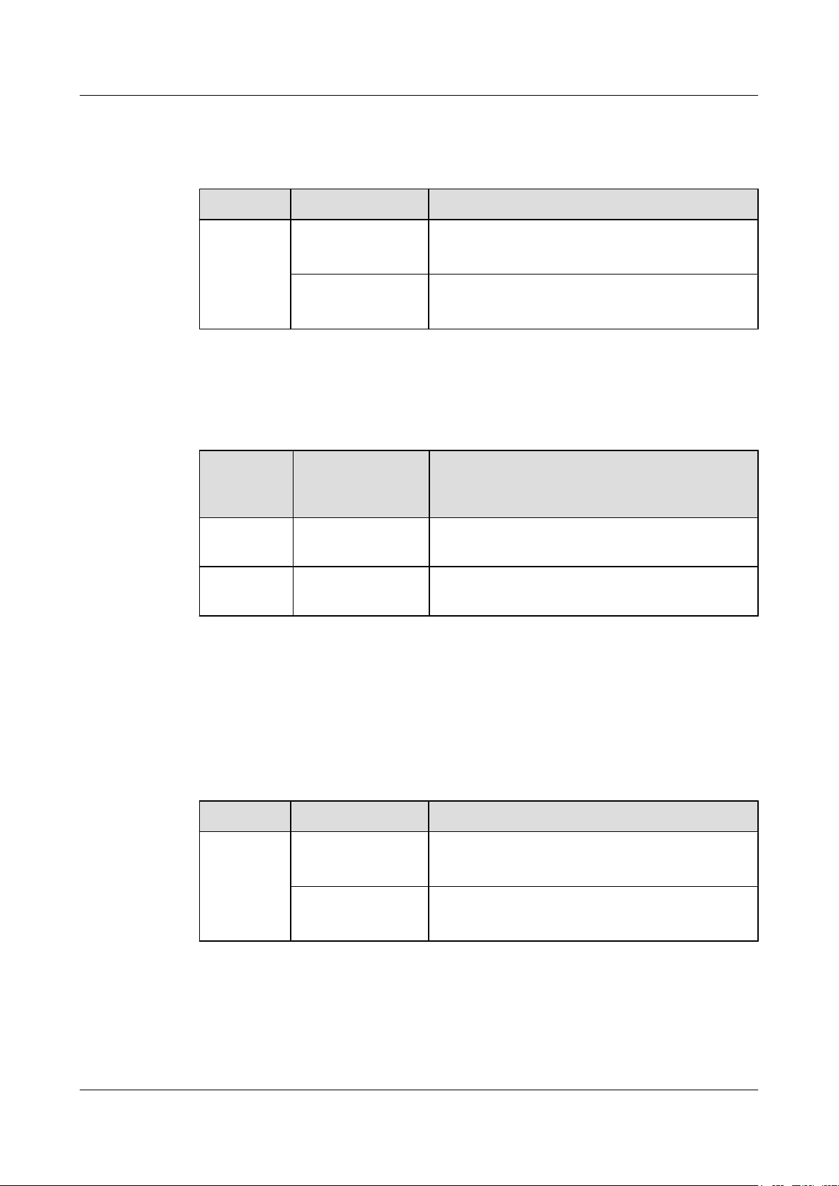
Available Models
Table 1-7 S6700 switch models available in V200R002C00
Series Model Maximum Number of Service Ports
S6700-EI S6700-24-EI 24 total:
Available Power Modules
Table 1-8 S6700 power modules available in V200R002C00
1 Version Support for Components
24 10GE SFP+ optical ports (10GE/GE auto-sensing)
S6700-48-EI 48 total:
48 10GE SFP+ optical ports (10GE/GE auto-sensing)
Power
Module
Type
AC power
module
DC power
module
Power Module Power Description
W0PSA5000 500 W AC power module
LS6W2PSD0500 500 W DC power module
1.5 Components Available in V200R003C00 Version
Available Models
Table 1-9 S6700 switch models available in V200R003C00
Series Model Maximum Number of Service Ports
S6700-EI S6700-24-EI 24 total:
24 10GE SFP+ optical ports (10GE/GE auto-sensing)
S6700-48-EI 48 total:
48 10GE SFP+ optical ports (10GE/GE auto-sensing)
Issue 12 (2015-07-31) Huawei Proprietary and Confidential
Copyright © Huawei Technologies Co., Ltd.
4
Page 14
S6700 Series Ethernet Switches
Hardware Description
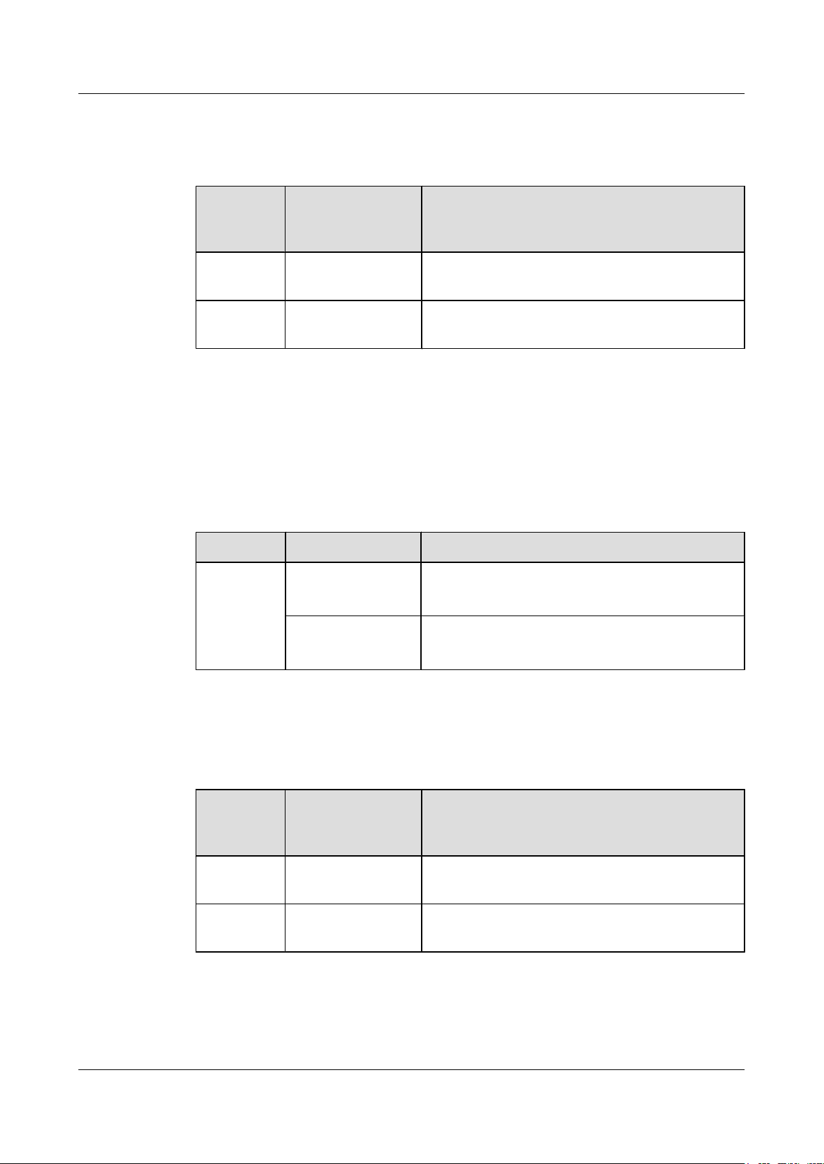
Available Power Modules
Table 1-10 S6700 power modules available in V200R003C00
1 Version Support for Components
Power
Module
Type
AC power
module
DC power
module
Power Module Power Description
W0PSA5000 500 W AC power module
LS6W2PSD0500 500 W DC power module
1.6 Components Available in V200R005C00 Version
Available Models
Table 1-11 S6700 switch models available in V200R005C00
Series Model Maximum Number of Service Ports
S6700-EI S6700-24-EI 24 total:
24 10GE SFP+ optical ports (10GE/GE auto-sensing)
S6700-48-EI 48 total:
48 10GE SFP+ optical ports (10GE/GE auto-sensing)
Available Power Modules
Table 1-12 S6700 power modules available in V200R005C00
Power
Module
Type
AC power
module
DC power
module
Power Module Description
W0PSA5000 500 W AC power module
LS6W2PSD0500 500 W DC power module
1.7 Components Available in V200R005C01 Version
Issue 12 (2015-07-31) Huawei Proprietary and Confidential
Copyright © Huawei Technologies Co., Ltd.
5
Page 15
S6700 Series Ethernet Switches
Hardware Description
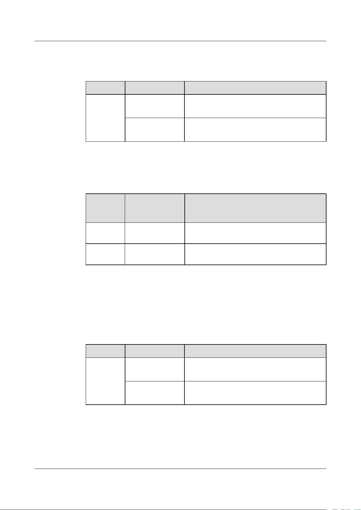
Available Models
Table 1-13 S6700 switch models available in V200R005C01
Series Model Maximum Number of Service Ports
S6700-EI S6700-24-EI 24 total:
Available Power Modules
Table 1-14 S6700 power modules available in V200R005C01
1 Version Support for Components
24 10GE SFP+ optical ports (10GE/GE auto-sensing)
S6700-48-EI 48 total:
48 10GE SFP+ optical ports (10GE/GE auto-sensing)
Power
Module
Type
AC power
module
DC power
module
Power Module Power Description
W0PSA5000 500 W AC power module
LS6W2PSD0500 500 W DC power module
1.8 Components Available in V200R005C02 Version
Available Models
Table 1-15 S6700 switch models available in V200R005C02
Series Model Maximum Number of Service Ports
S6700-EI S6700-24-EI 24 total:
24 10GE SFP+ optical ports (10GE/GE auto-sensing)
S6700-48-EI 48 total:
48 10GE SFP+ optical ports (10GE/GE auto-sensing)
Issue 12 (2015-07-31) Huawei Proprietary and Confidential
Copyright © Huawei Technologies Co., Ltd.
6
Page 16
S6700 Series Ethernet Switches
Hardware Description
Available Power Modules
Table 1-16 S6700 power modules available in V200R005C02
1 Version Support for Components
Power
Power Module Description
Module
Type
AC power
W0PSA5000 500 W AC power module
module
DC power
LS6W2PSD0500 500 W DC power module
module
1.9 Components Available in V200R008C00 Version
NOTE
The components marked * are the new components added to V200R008C00.
Chassis
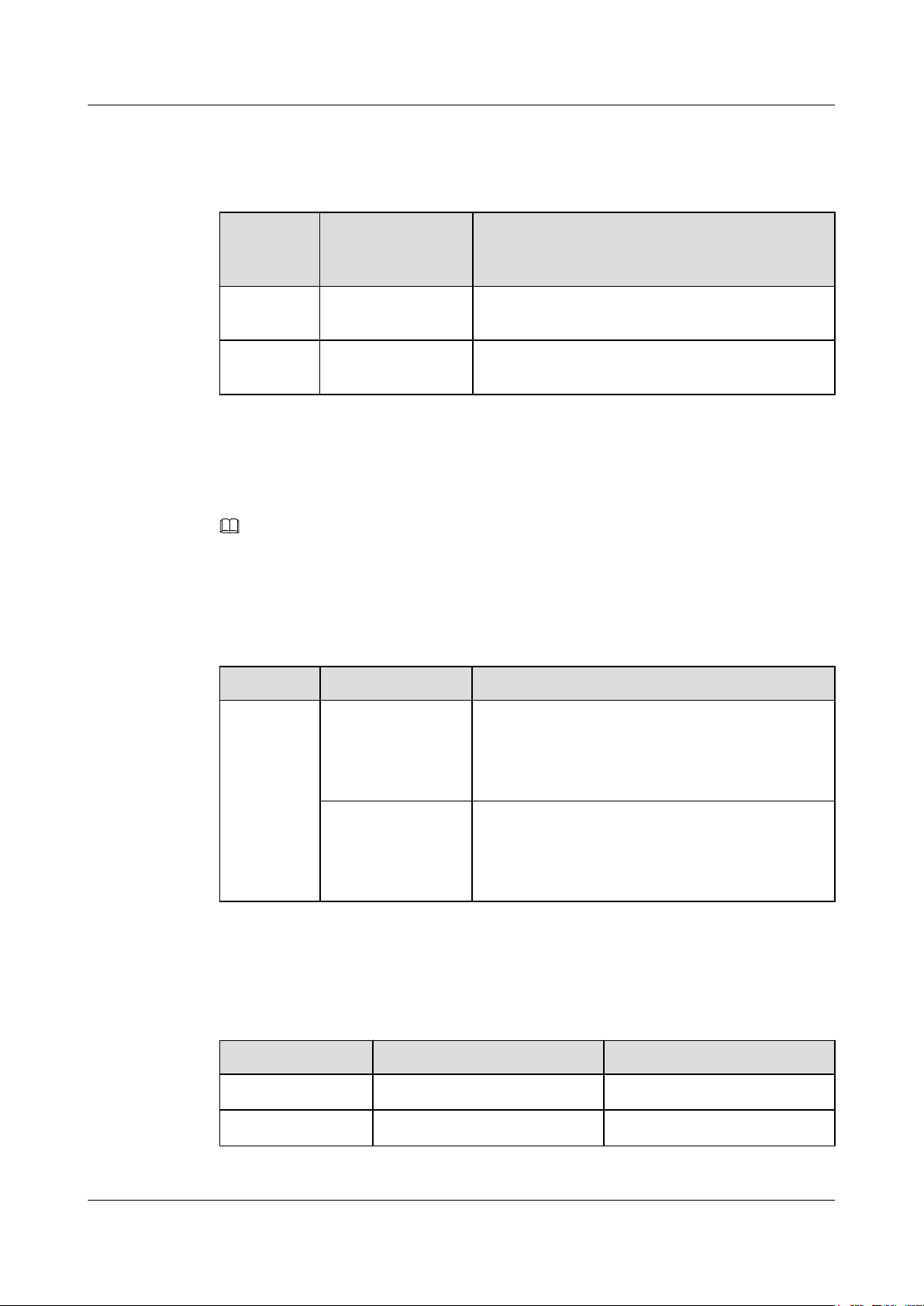
Table 1-17 S6700 switch models available in V200R008C00
Power Modules
Table 1-18 S6700 power modules available in V200R008C00
Series Model Maximum Number of Service Ports
S6720-EI S6720-30C-EI-24S-
*
AC
30 total:
24 10Gig SFP+ ports (10GE/GE auto-sensing), 2
40Gig QSFP+ ports, 4 40Gig QSFP+ ports on the rear
card
S6720-54C-EI-48S-
*
AC
54 total:
48 10Gig SFP+ ports (10GE/GE auto-sensing), 2
40Gig QSFP+ ports, 4 40Gig QSFP+ ports on the rear
card
Type Model Description
AC power module
DC power module
PAC-600WA-B
PDC-350WA-B
*
*
600 W AC power module
350 W DC power module
Issue 12 (2015-07-31) Huawei Proprietary and Confidential
Copyright © Huawei Technologies Co., Ltd.
7
Page 17

S6700 Series Ethernet Switches
Hardware Description 1 Version Support for Components
Cards
Table 1-19 S6700 cards available in V200R008C00
Type Model Description
Rear card
ES5D21Q04Q01
*
4-port 40 Gig QSFP+ interface
card, used in S6720-EI series
Issue 12 (2015-07-31) Huawei Proprietary and Confidential
Copyright © Huawei Technologies Co., Ltd.
8
Page 18

S6700 Series Ethernet Switches
Hardware Description 2 Chassis
2 Chassis
About This Chapter
2.1 Chassis Overview
2.2 Naming Conventions
2.3 Port Numbering Conventions
2.4 S6700-EI
2.5 S6720-EI
Issue 12 (2015-07-31) Huawei Proprietary and Confidential
Copyright © Huawei Technologies Co., Ltd.
9
Page 19
S6720-30C-EI-24S-AC
ABC D E F G H I
S6700 Series Ethernet Switches
Hardware Description 2 Chassis
2.1 Chassis Overview
The S6700 series Ethernet switches integrate the access and transmission functions to provide
reliable access/aggregation and high-quality transmission of services on enterprise networks.
The switches are built on an integrated hardware platform, and the hardware system consists of
the chassis, power module, fan module, extended cards, and Switch Control Unit (SCU).
The S6700 series are available in a variety of models for you to choose based on your network
requirements.
The S6700 series includes the S6700-EI and S6720-EI subseries, all of which are Layer 3
switches.
2.2 Naming Conventions
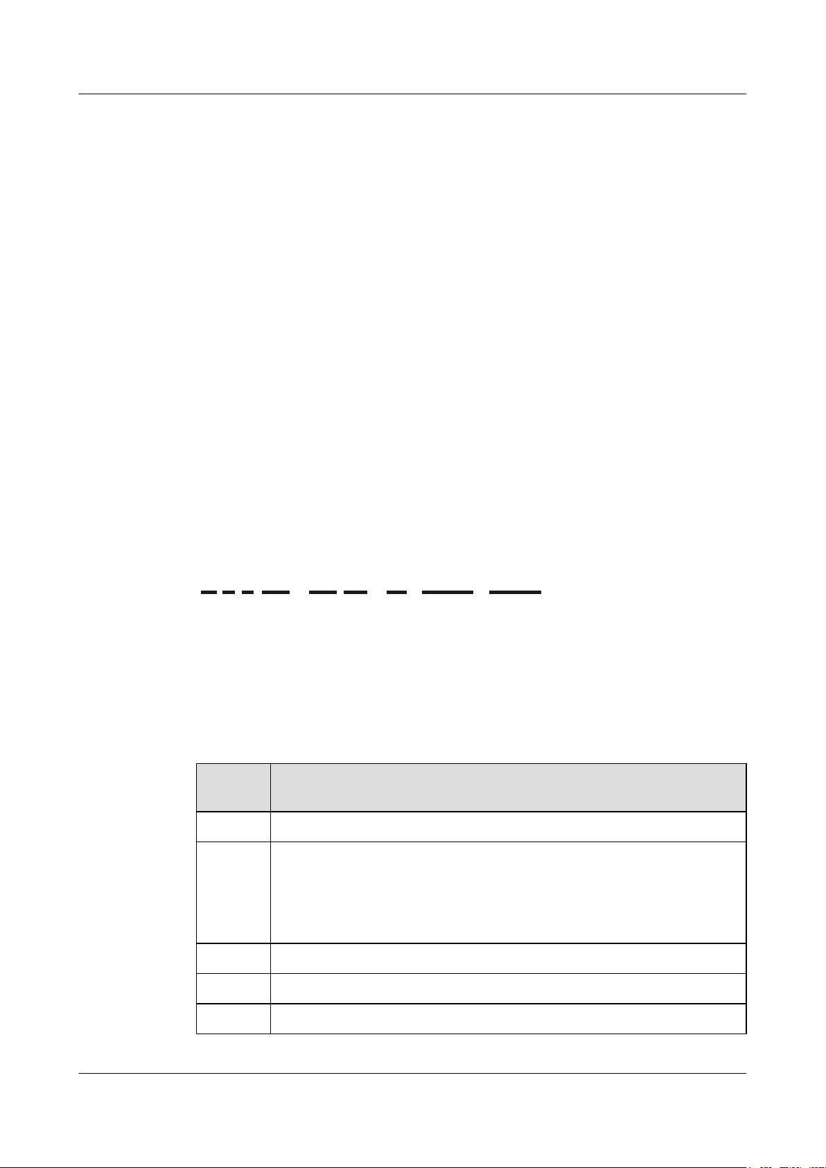
Figure 2-1 shows the switch naming conventions.
Figure 2-1 Switch naming conventions
Table 2-1 explains the switch naming conventions.
Table 2-1 Switch naming convention description
IdentifierDescription
A Switch
B
l 6: 10GE downlink ports
l 5: GE downlink ports
l 3: Layer 3 switch with 100M downlink ports
l 2: Layer 2 switch with 100M downlink ports
C 7: Enterprise series switch
D Product sub-series (such as 00 or 10)
E Maximum number of ports
Issue 12 (2015-07-31) Huawei Proprietary and Confidential
Copyright © Huawei Technologies Co., Ltd.
10
Page 20

S6700 Series Ethernet Switches
Hardware Description
IdentifierDescription
F Uplink port type:
G Device type
H Downlink port type:
2 Chassis
l C: The product supports extended cards and its uplink ports are provided by
an extended card or are fixed 40GE ports.
NOTE
If the product name does not contain this field, the switch has no uplink port.
l LI: lightweight version
l SI: standard version
l EI: enhanced version
l HI: high-level version, which supports high-performance operation,
administration, and maintenance (OAM) and built-in real-time clock (RTC)
l 24S: 24 downlink SFP+ optical ports
l 48S: 48 downlink SFP+ optical ports
I Power supply type:
l AC: switch using alternating current power supply
NOTE
S6720-EI models that support pluggable power modules are sold with AC power modules
(standard configuration), and their product names contain "-AC". However, the silkscreen
or nameplate on the chassis does not contain "-AC".
2.3 Port Numbering Conventions
Physical ports are numbered in the following way:
A single switch uses slot ID/subcard ID/port sequence number to identify physical ports.
l Slot ID: indicates the slot where the switch is located. The value is 0.
l Subcard ID: indicates the ID of a subcard.
l Port sequence number: indicates the sequence number of a port on the switch.
A stacked switch uses Stack ID/subcard ID/port sequence number to identify physical ports.
l Stack ID: indicates the ID of a stacked switch. The value ranges from 0 to 8.
l Subcard ID: indicates the ID of a subcard.
l Port sequence number: indicates the sequence number of a port on the switch.
Issue 12 (2015-07-31) Huawei Proprietary and Confidential
Copyright © Huawei Technologies Co., Ltd.
11
Page 21
1 3 5 7 9 11
2 4 6 8 10 12
2
1
111213
14
23
24
Quidway S6700 Series
CONSOLE
ETH
GREEN=SPEEDRED=STACK
LINK/ACT
PWR1
PWR2
SYS
MODE
STATUS STATUS
1
56 7 8 9 10
23 4
S6700 Series Ethernet Switches
Hardware Description
Table 2-2 Port numbering conventions
Port Numbering Diagram Description
2.4 S6700-EI
2.4.1 Version Mapping
2 Chassis
There are two rows of
service ports on the device.
These ports are numbered
from bottom to top and left
to right, starting from 1.
For example, the port on the
top left is numbered 0/0/2.
Table 2-3 lists the mapping between the S6700-EI chassis and software versions.
Table 2-3 Mapping between the S6700-EI chassis and software versions
Series Model Available Version
S6700-EI S6700-24-EI V100R006C00 to V200R005C02
S6700-48-EI V100R006C00 to V200R005C02
2.4.2 Appearance and Structure
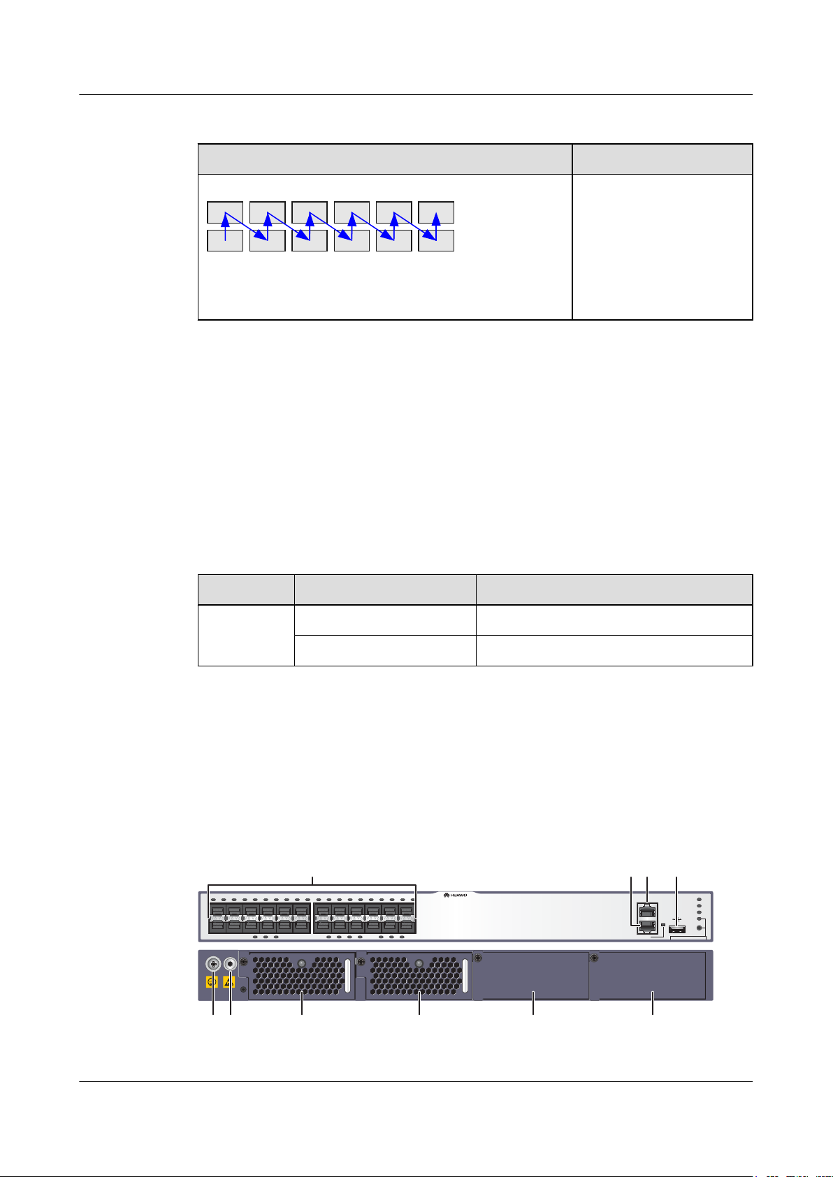
S6700-24-EI
Figure 2-2 Appearance of the S6700-24-EI
Issue 12 (2015-07-31) Huawei Proprietary and Confidential
Copyright © Huawei Technologies Co., Ltd.
12
Page 22

S6700 Series Ethernet Switches
Hardware Description 2 Chassis
1 Twenty-four 10GE SFP+ Ethernet
optical ports
Applicable modules and cables:
l GE optical module
l GE-CWDM optical module
l GE SFP copper module (applicable
in V200R001C01 and later versions)
l 10GE SFP+ optical module
l 10GE-CWDM optical module
(applicable in V200R005C00 and
later versions)
l 1 m or 3 m SFP+ copper cable
l 5 m SFP+ copper cable (applicable
in V200R005C02 version)
l 10 m SFP+ copper cable (applicable
in V200R001C00 and later versions)
l 3 m, 10 m AOC cables (applicable in
V200R003C00 and later versions)
One ETH management port
2
3 One console port 4 One USB port
5 Ground screw
NOTE
It is used with a ground cable.
7 Fan module slot 2
NOTE
Available fans: CX7E1FANA Fan Module
9 Power module slot 2
NOTE
Available power modules:
l 500 W AC Power Module
l 500 W DC Power Module
6 ESD jack
NOTE
When you install or maintain a switch, wear an
ESD wrist strap and insert the other end of the
ESD wrist strap into this ESD jack.
8 Fan module slot 1
NOTE
Available fans: CX7E1FANA Fan Module
10 Power module slot 1
NOTE
Available power modules:
l 500 W AC Power Module
l 500 W DC Power Module
Issue 12 (2015-07-31) Huawei Proprietary and Confidential
Copyright © Huawei Technologies Co., Ltd.
13
Page 23
2
1
111213
14
23
24
25
26
353637
38
47
48
Quidway S6700 Series
CONSOLE
ETH
GREEN=SPEEDRED=STACK
LINK/ACT
PWR1
PWR2
SYS
MODE
STATUS STATUS
1
56 7 8 9 10
23 4
S6700 Series Ethernet Switches
Hardware Description 2 Chassis
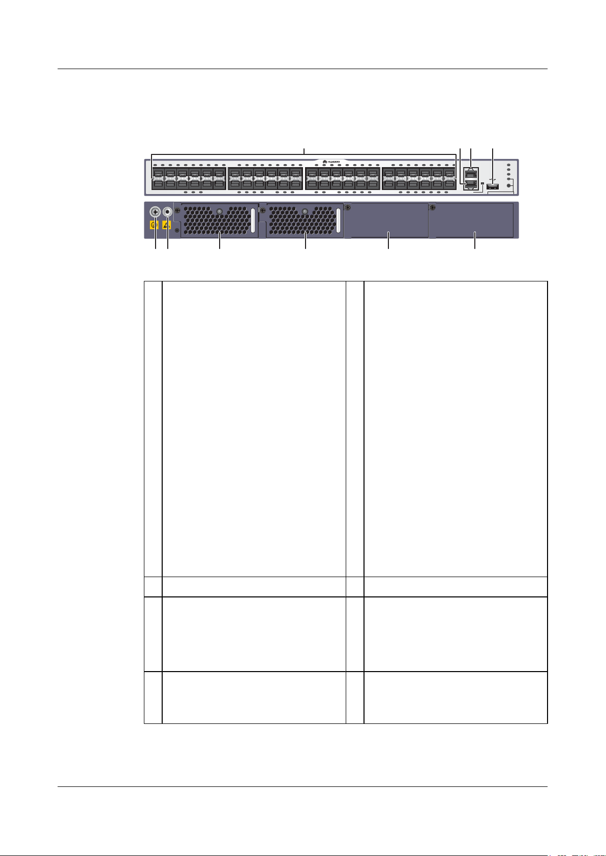
S6700-48-EI
Figure 2-3 Appearance of the S6700-48-EI
1 Forty-eight 10GE SFP+ Ethernet
optical ports
Applicable modules and cables:
l GE optical module
l GE-CWDM optical module
l GE SFP copper module (applicable
in V200R001C01 and later versions)
l 10GE SFP+ optical module
l 10GE-CWDM optical module
(applicable in V200R005C00 and
later versions)
l 1 m or 3 m SFP+ copper cable
l 5 m SFP+ copper cable (applicable
in V200R005C02 version)
l 10 m SFP+ copper cable (applicable
in V200R001C00 and later versions)
l 3 m, 10 m AOC cables (applicable in
V200R003C00 and later versions)
One ETH management port
2
3 One console port 4 One USB port
5 Ground screw
NOTE
It is used with a ground cable.
7 Fan module slot 2
NOTE
Available fans: CX7E1FANA Fan Module
Issue 12 (2015-07-31) Huawei Proprietary and Confidential
Copyright © Huawei Technologies Co., Ltd.
6 ESD jack
NOTE
When you install or maintain a switch, wear an
ESD wrist strap and insert the other end of the
ESD wrist strap into this ESD jack.
8 Fan module slot 1
NOTE
Available fans: CX7E1FANA Fan Module
14
Page 24
2
1
111213
14
23
24
Quidway S6700 Series
CONSOLE
ETH
GREEN=SPEEDRED=STACK
LINK/ACT
PWR1
PWR2
SYS
MODE
2
1
11
1
Quidway S6700 Series
6
CONSOLE
ETH
GREEN=SPEED RED=STACK
LINK/ACT
PWR1
PWR2
SYS
MODE
12
3
54
7
12
3
54
6
7
S6700 Series Ethernet Switches
Hardware Description 2 Chassis
9 Power module slot 2
NOTE
Available power modules:
l 500 W AC Power Module
l 500 W DC Power Module
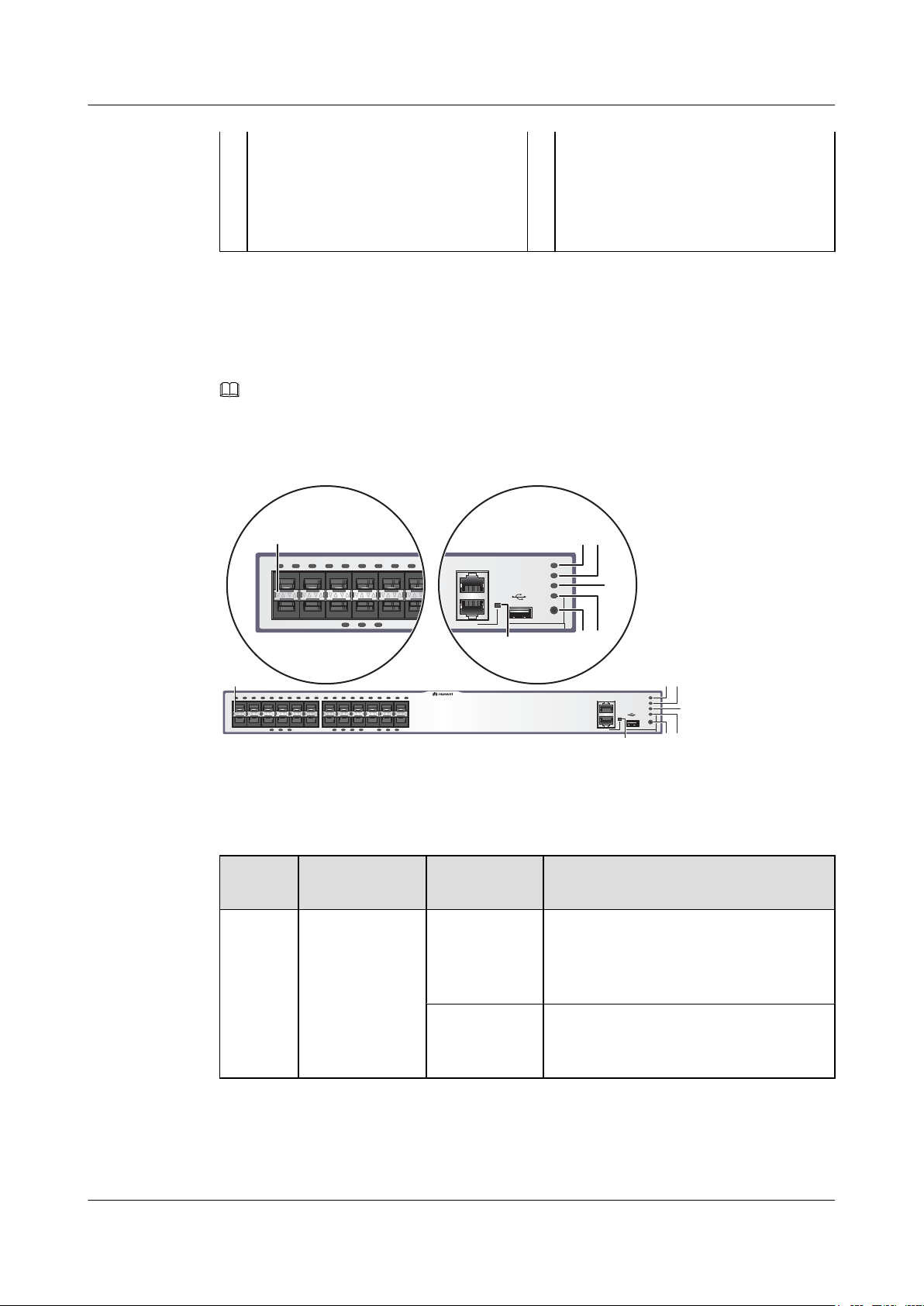
2.4.3 Indicator Description
S6700-24-EI
NOTE
Symbols and meanings of indicators on the S6700-48-EI are the same as those on the S6700-24-EI.
Figure 2-4 Indicators on the S6700-24-EI
10 Power module slot 1
NOTE
Available power modules:
l 500 W AC Power Module
l 500 W DC Power Module
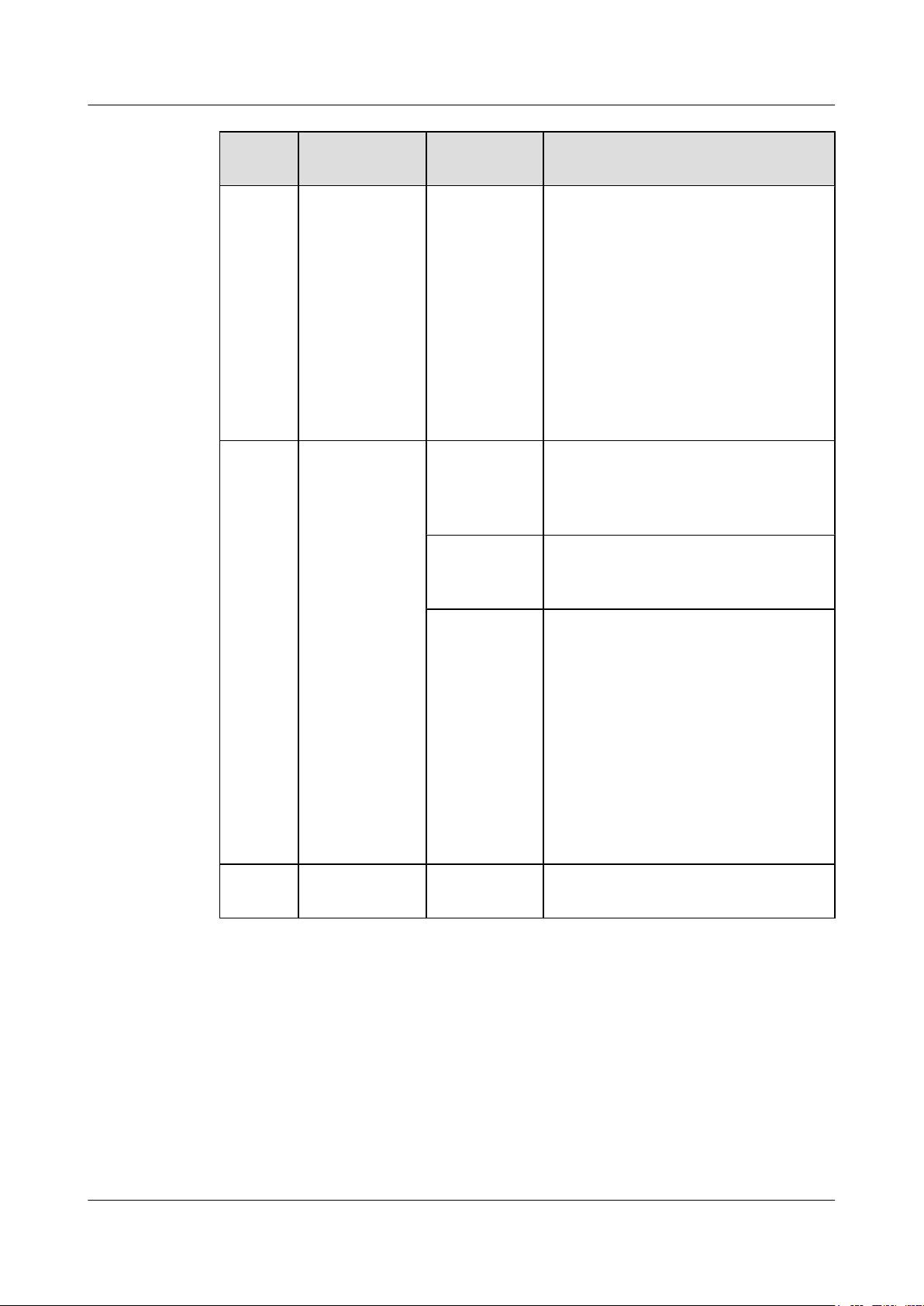
Table 2-4 Description of indicators on the switch
NumberIndicator/
Color Description
Button
1 PWR1: power
supply indicator
- Off: No power module is available in
power module slot 1, or the switch has only
one power module but the power module
does not work normally.
Green Steady on: A power module is installed in
power module slot 1 and is working
normally.
Issue 12 (2015-07-31) Huawei Proprietary and Confidential
Copyright © Huawei Technologies Co., Ltd.
15
Page 25
S6700 Series Ethernet Switches
Hardware Description 2 Chassis
NumberIndicator/
Button
2
PWR2: power
supply indicator
Color Description
Red Steady on: The switch has two power
modules installed. Any of the following
situations occurs in power module slot 1:
l A power module is available in this slot
but its power switch is in the OFF
position.
l A power module is available in this slot
but it is not connected to a power
source.
l The power module in power module
slot 1 fails.
- Off: No power module is available in
power module slot 2, or the switch has only
one power module but the power module
does not work normally.
Green Steady on: A power module is installed in
power module slot 2 and is working
normally.
Red Steady on: The switch has two power
modules installed. Any of the following
situations occurs in power module slot 2:
l A power module is available in this slot
but its power switch is in the OFF
position.
l A power module is available in this slot
but it is not connected to a power
source.
l The power module in power module
slot 2 fails.
3
SYS: system
- Off: The system is not running.
status indicator
Issue 12 (2015-07-31) Huawei Proprietary and Confidential
Copyright © Huawei Technologies Co., Ltd.
16
Page 26

S6700 Series Ethernet Switches
Hardware Description 2 Chassis
NumberIndicator/
Button
Color Description
Green Indicator states and meaning in V100R006
version:
l Steady on: The system is not operating
properly or is starting.
l Slow blinking: The system is operating
properly.
l Fast blinking: The system is copying
the system software and configuration
file from a USB flash drive.
Indicator states and meaning in V200R001
and later versions:
l Fast blinking: The system is starting or
is copying the system software and
configuration file from a USB flash
drive during a USB-based upgrade.
l Slow blinking: The system is running
normally.
Yellow
l Steady on: The system is performing
self-check during startup (only
applicable to V100R006).
4 MODE: mode
indicator
l Blinking: The system has been
successfully upgraded using a USB
flash drive and the switch has restarted.
You can remove the USB flash drive
from the switch.
Red
l Steady on: After registering, the system
does not operate properly, or a fan or
temperature alarm has been generated.
l Blinking: An error occurred during
USB-based upgrade and the system
failed to be upgraded after a USB flash
drive is inserted.
- Off: The service port indicators are in the
status mode (default). In the status mode,
the service port indicator shows the port
link or activity state.
Green Steady on: The service port indicators
show the port speed. After 45 seconds, the
service port indicators automatically
restore to the status mode.
Issue 12 (2015-07-31) Huawei Proprietary and Confidential
Copyright © Huawei Technologies Co., Ltd.
17
Page 27

S6700 Series Ethernet Switches
Hardware Description 2 Chassis
NumberIndicator/
Button
5 Mode switch
button
6
Service port
indicator
Color Description
Red Steady on: The service port indicators
show the stack ID of the switch. After 45
seconds, the service port indicators
automatically restore to the status mode.
-
l When you press this button once, the
mode indicator turns green and the
service port indicators show the speed
of each service port.
l When you press this button a second
time, the mode indicator turns red and
the service port indicators show the
stack status.
l When you press this button a third time,
the mode indicator turns off.
If you do not press the button within 45
seconds, the mode indicator restores to
status mode.
Meanings of service port indicators vary in different modes.
For details, see Table 2-5.
7 ETH indicator Green
l Off: No link is established on the port.
l Steady on: The port is connected.
l Blinking: The port is sending or
receiving data.
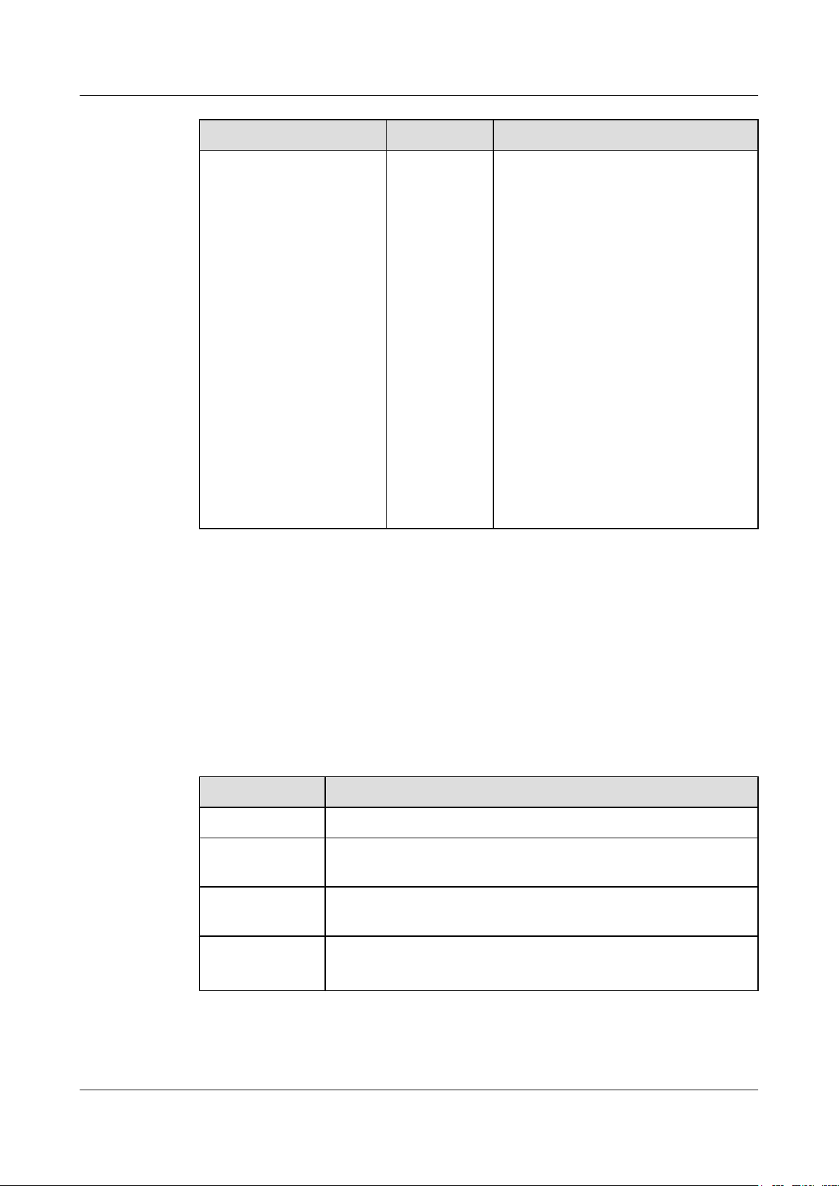
Table 2-5 Description of service port indicators in different modes
Display Mode Color Description
Status - Off: The port is not connected or has been
shut down.
Green Steady on: The port is connected.
Yellow Blinking: The interface is sending or
receiving data.
Speed Green and
yellow
l Off: The port is not connected or has
been shut down.
l Both steady on: The port is operating at
a speed of 1000 Mbit/s.
l Both blinking: The port is operating at
Issue 12 (2015-07-31) Huawei Proprietary and Confidential
Copyright © Huawei Technologies Co., Ltd.
a speed of 10 Gbit/s.
18
Page 28
S6700 Series Ethernet Switches
Hardware Description
Display Mode Color Description
2 Chassis
Stack Green and
yellow
l Off: Port indicators do not show the
stack ID of the switch.
l If both indicators are steady on, the
switch is not a master switch:
– If the indicator of a port is steady on,
the number of this port is the stack
ID of the switch.
– If the first nine port indicators of the
switch are steady on, the stack ID of
the switch is 0.
l If both indicators are blinking, the
switch is a master switch:
– If the indicator of a port is blinking,
the number of this port is the stack
ID of the switch.
– If the first nine port indicators of the
switch are blinking, the stack ID of
the switch is 0.
2.4.4 Port Description
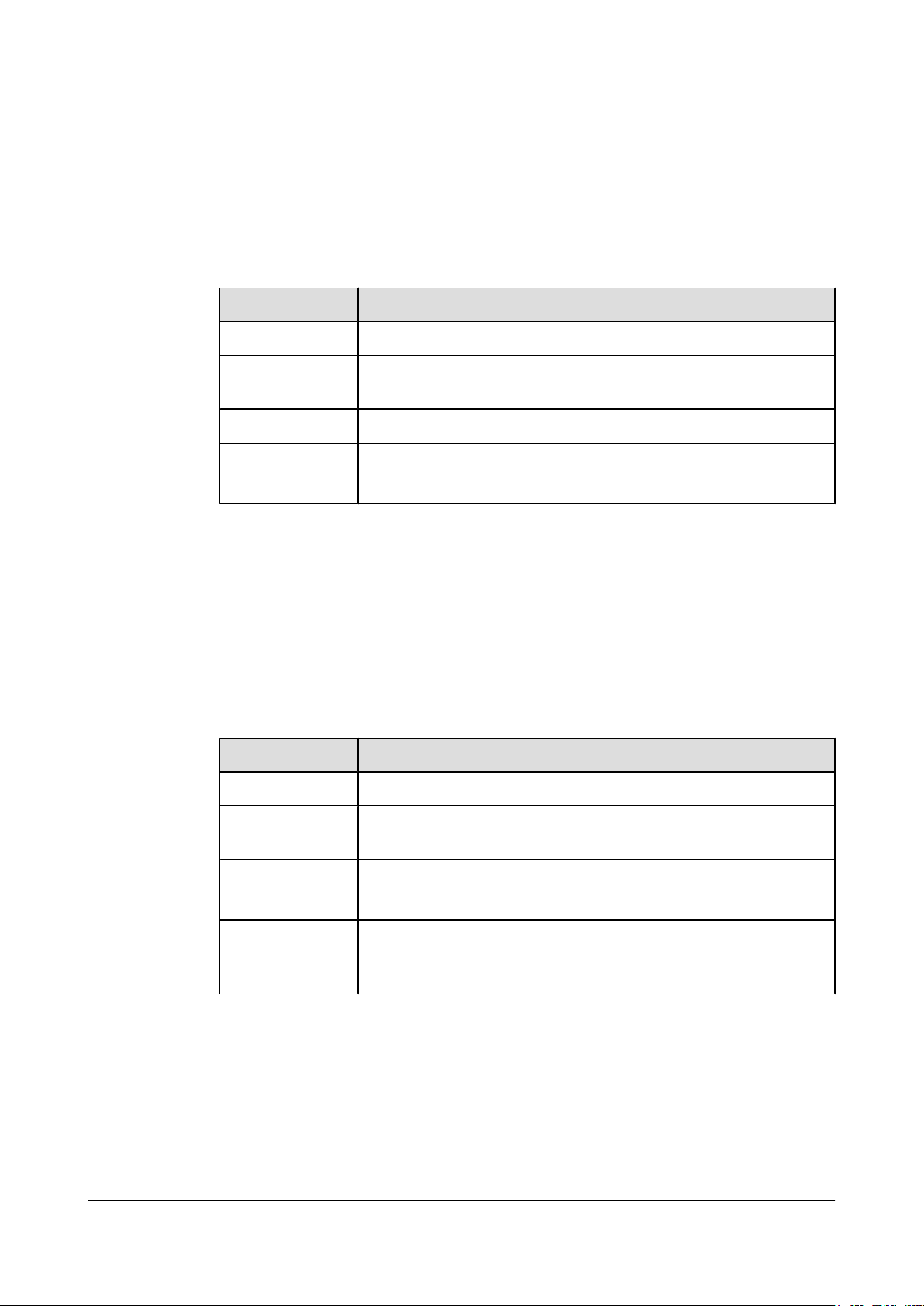
10GE SFP+ Ethernet Optical Port
A 10GE SFP+ Ethernet optical port supports auto-sensing to 1000 Mbit/s. It receives and sends
service data at 1 Gbit/s or 10 Gbit/s. Table 2-6 describes the attributes of a 10GE SFP+ Ethernet
optical port.
Table 2-6 Attributes of a 10GE SFP+ Ethernet optical port
Attribute Description
Connector type LC/PC
Optical port
attributes
Standards
compliance
Working mode GE/10GE auto-sensing
Depend on the optical module used (see 7.4.1 SFP/eSFP Modules and
7.4.2 SFP+ Modules)
IEEE802.3ae
Full duplex
Issue 12 (2015-07-31) Huawei Proprietary and Confidential
Copyright © Huawei Technologies Co., Ltd.
19
Page 29
S6700 Series Ethernet Switches
Hardware Description
Console Port
The console port is connected to a console for on-site configuration. The port must use a console
cable. The console port is used when a switch is powered on for the first time. Table 2-7 describes
the attributes of the console port.
Table 2-7 Attributes of a console port
Attribute Description
Connector type RJ45
2 Chassis
Standards
compliance
Working mode Duplex Universal Asynchronous Receiver/Transmitter (UART)
Baud rate 9600 bit/s, 19200 bit/s, 38400 bit/s, 57600 bit/s, or 115200 bit/s
ETH Management Port
You can connect a switch to a configuration terminal or network management workstation
through the ETH management port to configure the switch locally or remotely. The port must
use a network cable. For details on how to use the ETH management port, see the Configuration
Guide - Basic Configurations. Table 2-8 describes the attributes of an ETH management port.
Table 2-8 Attributes of an ETH management port
Attribute Description
Connector type RJ45
RS-232
Default value: 9600 bit/s
Standards
compliance
Working mode 10/100 Mbit/s auto-sensing
Maximum
transmission
distance
IEEE802.3
Full duplex
100 m
USB Port
The USB port can have a USB flash drive connected to upgrade the switch, or transfer
configuration files or other files. The USB flash drive used on a switch must comply with USB
1.1 and support the Linux operating system. Table 2-9 lists the USB flash drives applicable to
a switch.
Issue 12 (2015-07-31) Huawei Proprietary and Confidential
Copyright © Huawei Technologies Co., Ltd.
20
Page 30
S6700 Series Ethernet Switches
Hardware Description 2 Chassis
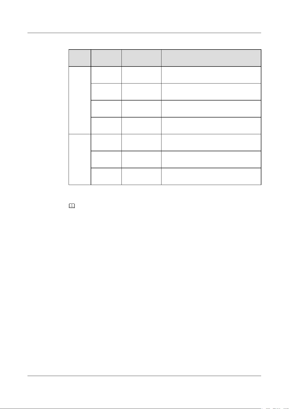
Table 2-9 USB flash drives applicable to a switch
CapacityVendor Model Remarks
4 GB Netac U208 You can buy Netac USB 4 GB flash drives from
Huawei or other vendors.
SanDisk Cruzer Blade Huawei does not offer this USB flash drive, and
you must buy it from other vendors.
JTAG port
HewlettPackard
v218G Huawei does not offer this USB flash drive, and
you must buy it from other vendors.
PNY M1 Huawei does not offer this USB flash drive, and
you must buy it from other vendors.
8 GB Netac U208 Huawei does not offer this USB flash drive, and
you must buy it from other vendors.
HewlettPackard
v225w Huawei does not offer this USB flash drive, and
you must buy it from other vendors.
STEC SLUFD8GU2TUIHuawei does not offer this USB flash drive, and
you must buy it from other vendors.
NOTE
Huawei is not responsible for maintenance service of USB flash drives purchased from other vendors.
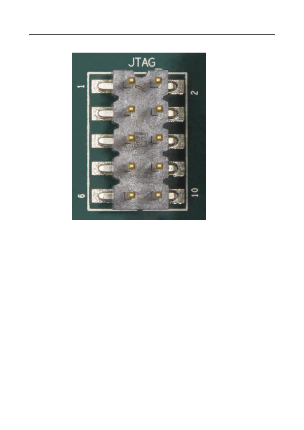
Figure 2-5 shows the JTAG port. The JTAG port is an internal port of the switch and is used to
check and diagnose equipment faults.
Issue 12 (2015-07-31) Huawei Proprietary and Confidential
Copyright © Huawei Technologies Co., Ltd.
21
Page 31
S6700 Series Ethernet Switches
Hardware Description
Figure 2-5 JTAG port
2 Chassis
2.4.5 Power Supply
Power Supply Configuration
On a S6700-EI switch, one or two power modules can be configured.
When two power modules are used, they work in 1+1 backup mode to provide power for the
device. In the versions earlier than V200R005C00, the AC and DC power modules cannot be
configured on the same device, while in V200R005C00 and later versions, they can be
configured on the same device.
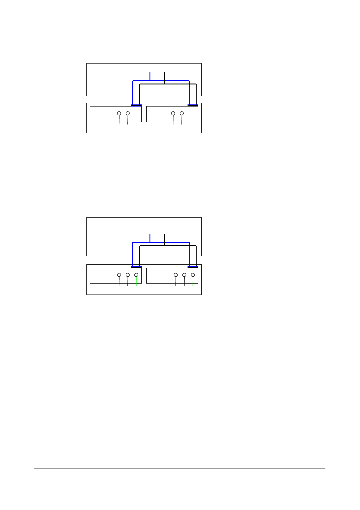
Figure 2-6 shows the power supply connections of dual DC power modules. After DC power
is transmitted to the PWR module, the PWR module provides -53 V output voltage, and the
motherboard provides power for the entire device.
Issue 12 (2015-07-31) Huawei Proprietary and Confidential
Copyright © Huawei Technologies Co., Ltd.
22
Page 32
PWR2
NEG RTN
Motherboard
GND-53V
PWR1
NEG RTN
PWR2
L N
Motherboard
GND-53V
PGND
PWR1
L N PGND
S6700 Series Ethernet Switches
Hardware Description 2 Chassis
Figure 2-6 Power supply connections of dual DC power modules
NEG: Negative cable RTN: Positive cable GND: -53 V reference ground
Figure 2-7 shows the power supply connections of dual AC power modules. After AC power
is transmitted to the PWR module, the PWR module provides -53 V output voltage, and the
motherboard provides power for the entire device.
Figure 2-7 Power supply connections of dual AC power modules
L: Live wire
N: Neutral wire PGND: Protective ground wire GND: -53 V reference ground
2.4.6 Heat Dissipation
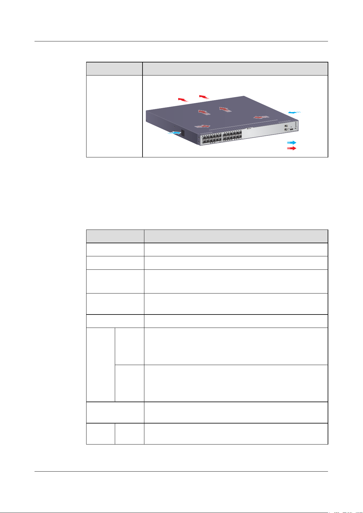
Table 2-10 describes the heat dissipation methods of the S6700-EI.
Issue 12 (2015-07-31) Huawei Proprietary and Confidential
Copyright © Huawei Technologies Co., Ltd.
23
Page 33
PWR1
PWR2
SYS
MODE
GREEN=SPEED RED=STACK
LINK/ACT
CONSOLE
ETH
Quidway S6700 Series
Cold air
Hot air
S6700 Series Ethernet Switches
Hardware Description 2 Chassis
Table 2-10 S6700-EI heat dissipation method
Model Heat Dissipation Method
l S6700-24-EI
l S6700-48-EI
2.4.7 Specifications
Table 2-11 lists specifications of the S6700-EI.
Table 2-11 Specifications of the S6700-EI
Item Description
Memory (RAM) 512 MB
Forcible heat dissipation
The air flows in from the left and right and flows out from the rear.
Flash 64 MB
Mean time between
failures (MTBF)
Mean time to repair
l S6700-24-EI: 34.54 years
l S6700-48-EI: 33.76 years
2 hours
(MTTR)
Availability > 0.99999
Surge
protecti
on
Service
port
protectio
-
n
Power
supply
l AC: ±2 kV in differential mode; ±4 kV in common mode
l DC: ±1 kV in differential mode; ±2 kV in common mode
protectio
n
Dimensions (W x D
442.0 mm x 420.0 mm x 43.6 mm
x H)
Weight Fully
≤ 8.5 kg
loaded
Issue 12 (2015-07-31) Huawei Proprietary and Confidential
Copyright © Huawei Technologies Co., Ltd.
24
Page 34
S6700 Series Ethernet Switches
Hardware Description 2 Chassis
Item Description
Empty
≤ 5 kg
loaded
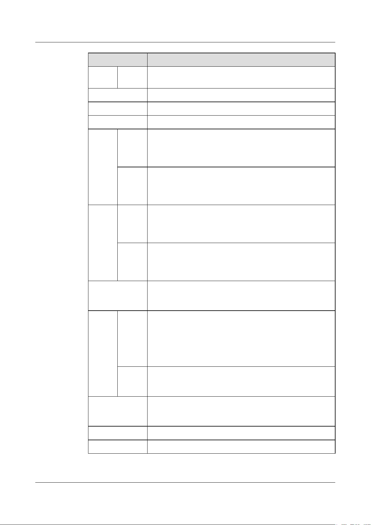
Stack port 10GE SFP+ port (A maximum of eight 10GE SFP+ ports is supported.)
RPS Not supported
PoE Not supported
Input
DC
voltage
Rated
input
voltage
-48 V DC to -60 V DC
range
Maximu
-38.4 V DC to -72 V DC
m
voltage
range
Input
AC
voltage
Rated
input
voltage
100 V AC to 240 V AC, 50/60 Hz
range
Maximu
90 V AC to 264 V AC, 47 Hz to 63 Hz
m
voltage
range
Maximum power
(100% throughput,
l S6700-24-EI: 153.6 W
l S6700-48-EI: 240 W
full speed of fans)
Temper
ature
Operatin
g
temperat
ure
Storage
-5°C to +50°C (at 0 m to 1800 m altitude)
NOTE
l If using SFP+ optical modules of 40 km or longer transmission distances,
the operating temperature of S6700-EI is between -5°C and 45°C.
l When the altitude is between 1800 m and 5000 m, the highest operating
temperature reduces 1°C every time the altitude increases 220 m.
-40°C to +70°C
temperat
ure
Noise under normal
Less than 55 dBA
temperature (27°C,
sound power)
Relative humidity 5% RH to 95% RH, noncondensing
Operating altitude 0 m to 5000 m
Issue 12 (2015-07-31) Huawei Proprietary and Confidential
Copyright © Huawei Technologies Co., Ltd.
25
Page 35
CARD FAN
PWR2 PWR1
STATUS
FAN-060B-B
S6720-30C-EI-24S
12
1234567891011 12
13 14 15 16 17 18 19 20 21 22 23 24
CONSOLE
ETH
MODE
HUAWEI
STCK
SPED
STAT
SYS
PWR1
PWR2
1234
67
8 9 10 11
5
S6700 Series Ethernet Switches
Hardware Description 2 Chassis
Item Description
Certification
2.5 S6720-EI
2.5.1 Version Mapping
Table 2-12 lists the mapping between the S6720-EI series switches and software versions.
Table 2-12 Mappings between the S6720-EI series switches and software versions
Series Model Available Version
S6720-EI S6720-30C-EI-24S-AC V200R008C00 and later versions
l EMC certification
l Safety certification
l Manufacturing certification
S6720-54C-EI-48S-AC V200R008C00 and later versions
2.5.2 Appearance and Structure
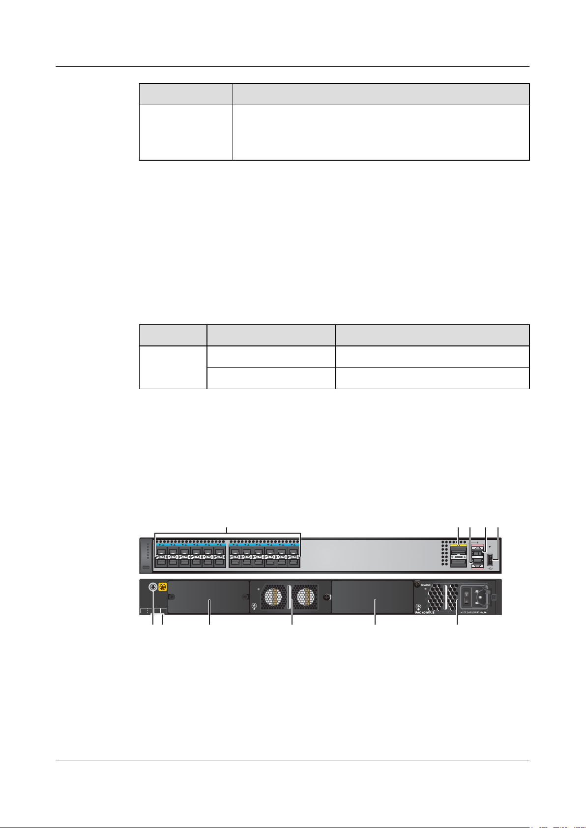
S6720-30C-EI-24S-AC
Figure 2-8 Appearance of the S6720-30C-EI-24S-AC
Issue 12 (2015-07-31) Huawei Proprietary and Confidential
Copyright © Huawei Technologies Co., Ltd.
26
Page 36

S6700 Series Ethernet Switches
Hardware Description 2 Chassis
1 Twenty-four 10GE SFP+ Ethernet
Two 40GE QSFP+ optical ports
2
optical ports
Applicable modules and cables:
Applicable modules and cables:
l GE optical module
l GE-CWDM optical module
l GE-DWDM optical module
l GE copper module (only work at
1000 Mbit/s)
l 10GE SFP+ optical module
(OSXD22N00 not supported)
l QSFP+ optical module
l 1 m, 3 m, 5 m QSFP+ high-speed
copper cables (QSFP+ to QSFP+)
l 1 m, 3 m, 5 m QSFP+ high-speed
copper cables (QSFP+ to 4*SFP+)
NOTE
A 40GE QSFP+ optical port can be split into
four 10GE ports.
l 10GE-CWDM optical module
l 1 m, 3 m, 5 m, 10 m SFP+ high-speed
copper cables
l 3 m, 10 m AOC cables
One ETH management port 4 One console port
3
NOTE
It is used with a console cable. The console
cable is not delivered with the switch and needs
to be separately purchased if needed.
5 One USB port 6 Ground screw
NOTE
It is used with a ground cable.
7 Equipment serial number (ESN) label
NOTE
You can draw it out to view the ESN and MAC
address of the switch.
9 Fan module slot
NOTE
Applicable fan module:
FAN-060B-B fan module
11 Power module slot 1
NOTE
l 350 W DC power module
l 600 W AC power module
8 Extended card slot
Applicable card:
l ES5D21Q04Q01
10 Power module slot 2
NOTE
l 350 W DC power module
l 600 W AC power module
- -
Issue 12 (2015-07-31) Huawei Proprietary and Confidential
Copyright © Huawei Technologies Co., Ltd.
27
Page 37
S6720-54C-EI-48S
12
1234567891011 12
13 14 15 16 17 18 19 20 21 22 23 24 25 26 27 28 29 30 31 32 33 34 35 36 37 38 39 40 41 42 43 44 45 46 47 48
CONSOLE
ETH
MODE
HUAWEI
STCK
SPED
STAT
SYS
PWR1
PWR2
CARD FAN
PWR2 PWR1
STATUS
FAN-060B-B
1234
67
8 9 10 11
5
S6700 Series Ethernet Switches
Hardware Description 2 Chassis
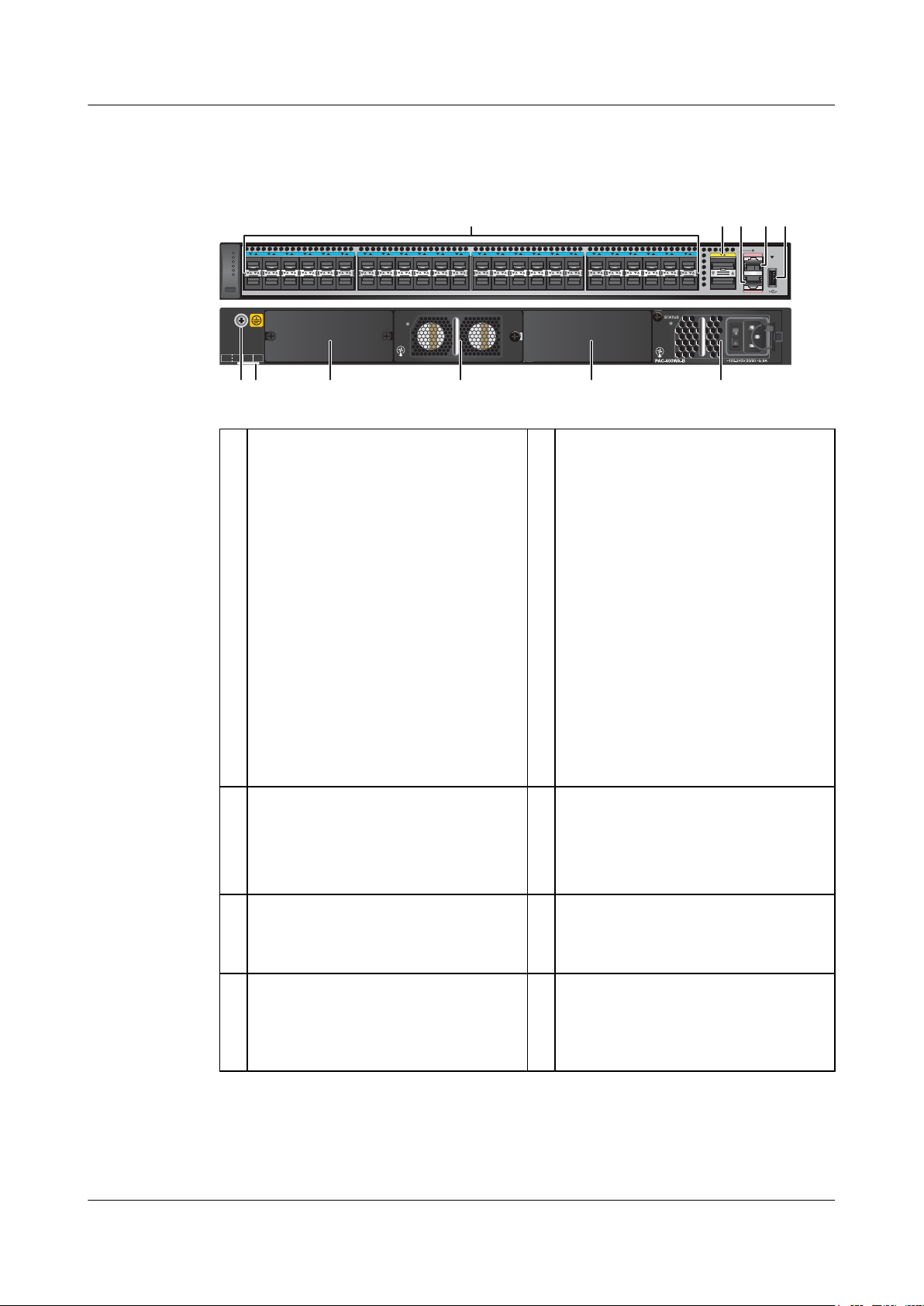
S6720-54C-EI-48S-AC
Figure 2-9 Appearance of the S6720-54C-EI-48S-AC
1 Forty-eight 10GE SFP+ Ethernet
Two 40GE QSFP+ optical ports
2
optical ports
Applicable modules and cables:
Applicable modules and cables:
l GE optical module
l GE-CWDM optical module
l GE-DWDM optical module
l GE copper module (only work at
1000 Mbit/s)
l 10GE SFP+ optical module
(OSXD22N00 and SFP-10G-ZR not
l QSFP+ optical module
l 1 m, 3 m, 5 m QSFP+ high-speed
copper cables (QSFP+ to QSFP+)
l 1 m, 3 m, 5 m QSFP+ high-speed
copper cables (QSFP+ to 4*SFP+)
NOTE
A 40GE QSFP+ optical port can be split into
four 10GE ports.
supported)
l 1 m, 3 m, 5 m, 10 m SFP+ high-speed
copper cables
l 3 m, 10 m AOC cables
One ETH management port 4 One console port
3
NOTE
It is used with a console cable. The console
cable is not delivered with the switch and needs
to be separately purchased if needed.
5 One USB port 6 Ground screw
NOTE
7 Equipment serial number (ESN) label
NOTE
You can draw it out to view the ESN and MAC
address of the switch.
Issue 12 (2015-07-31) Huawei Proprietary and Confidential
Copyright © Huawei Technologies Co., Ltd.
8 Extended card slot
Applicable card:
l ES5D21Q04Q01
It is used with a ground cable.
28
Page 38
S6700 Series Ethernet Switches
Hardware Description 2 Chassis
2.5.3
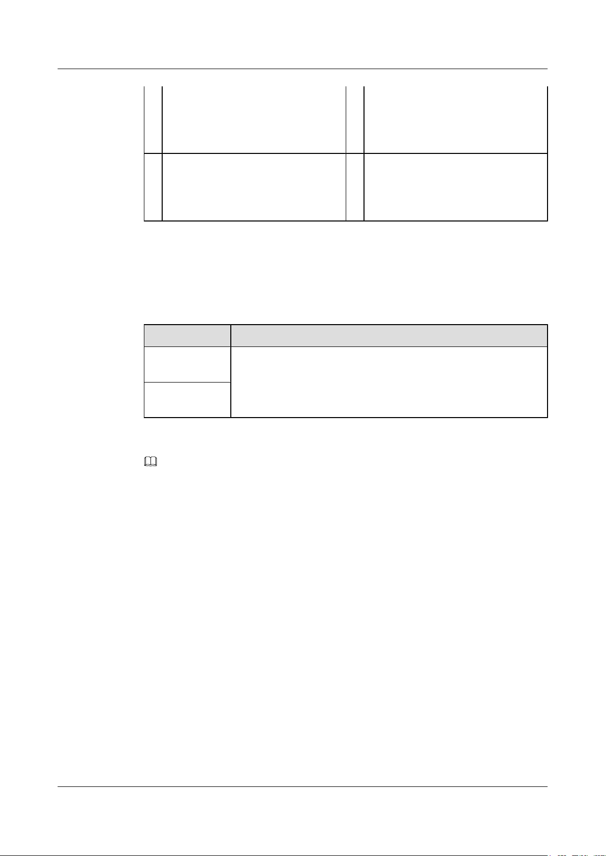
9 Fan module slot
NOTE
Applicable fan module:
FAN-060B-B fan module
11 Power module slot 1
NOTE
l 350 W DC power module
l 600 W AC power module
Indicator Description
Table 2-13 is a quick reference table for indicators of S6720-EI switches.
Table 2-13 S6720-EI indicator quick reference table
Switch Model Indicator Description
S6720-30CEI-24S-AC
S6720-54CEI-48S-AC
Symbols and meanings of indicators on the S6720-54C-EI-48S-AC are
the same as those on the S6720-30C-EI-24S-AC. S6720-30C-EI-24S-
AC is used as an example here.
10 Power module slot 2
NOTE
l 350 W DC power module
l 600 W AC power module
- -
NOTE
Hold down this button for 6 seconds and release it to start the web initial login mode. Either of the following
situations will occur:
l If the switch has no configuration file, the system attempts to enter the web initial login mode. In this
mode, the status of mode indicators is as follows:
l If the system enters the web initial login mode successfully, all mode indicators turn green and
stay on for a maximum of 10 minutes.
l If the system fails to enter the initial login mode, all mode indicators fast blink for 10 seconds
and then restore to the default states.
l If the switch has a configuration file, the system cannot enter the web initial login mode. In this case,
all mode indicators fast blink for 10 seconds, and then return to the default states.
Issue 12 (2015-07-31) Huawei Proprietary and Confidential
Copyright © Huawei Technologies Co., Ltd.
29
Page 39
S6720-30C-EI-24S
12
1234567891011 12
13 14 15 16 17 18 19 20 21 22 23 24
CONSOLE
ETH
MODE
HUAWEI
STCK
SPED
STAT
SYS
PWR1
PWR2
S6720-30C-EI-24S
12345
MODE
HUAWEI
STCK
SPED
STAT
SYS
PWR1
PWR2
1723
654
8
8
12
CONSOLE
ETH
91110
1
9
10 11
7
23
65
4
8
8
S6700 Series Ethernet Switches
Hardware Description 2 Chassis
S6720-30C-EI-24S-AC
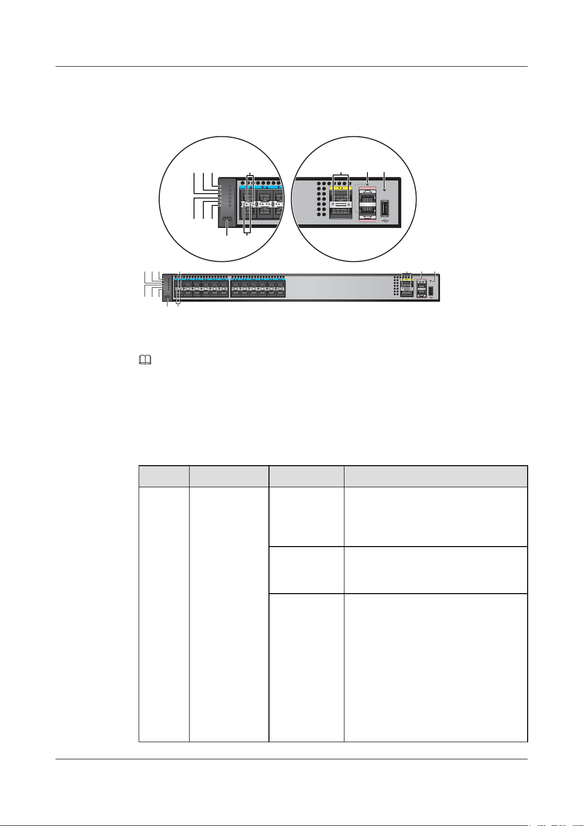
Figure 2-10 Indicators on the S6720-30C-EI-24S-AC
NOTE
The S6720-EI series switches provide a command that can turn on the fault indicators to help field
maintenance personnel find a faulty switch.
The SYS indicator and mode indicators (STAT, SPED, and STCK) are used as fault indicators. When an
S6720-EI switch is faulty, you can run the command to turn on the fault indicators. Then the SYS indicator
and mode indicators fast blink red to help field maintenance personnel quickly find the faulty switch.
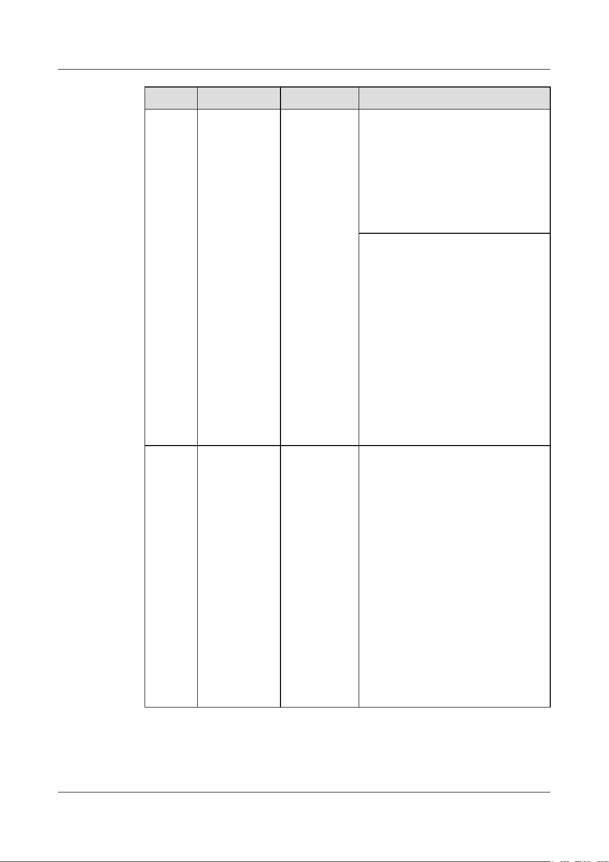
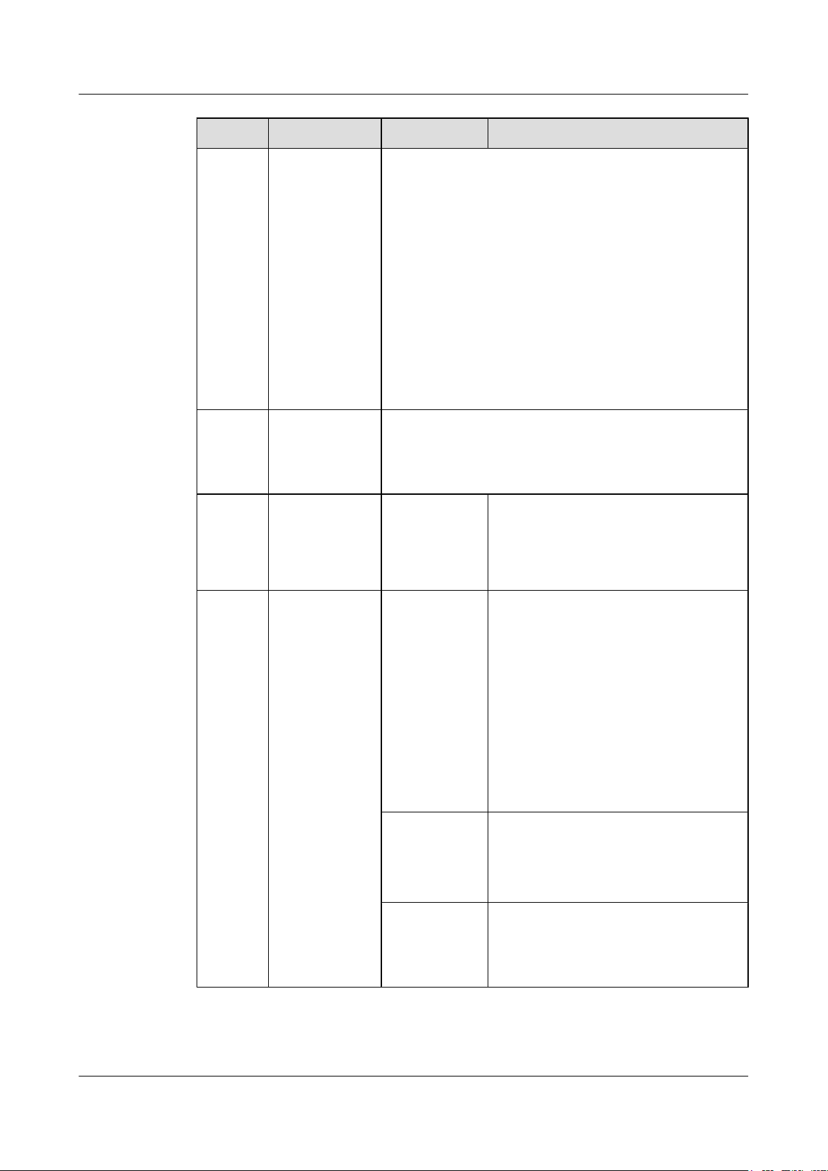
Table 2-14 Description of indicators on the switch
No. Indicator Color Description
1 PWR1: power
module indicator
- Off: No power module is available in
power module slot 1, or the switch has only
one power module but the power module
does not work normally.
Green Steady on: A power module is installed in
power module slot 1 and is working
normally.
Yellow Steady on: The switch has two power
modules installed. Any of the following
situations occurs in power module slot 1:
l A power module is available in this slot
but its power switch is in OFF position.
l A power module is available in this slot
but it is not connected to a power
source.
l The power module in this slot has
failed.
Copyright © Huawei Technologies Co., Ltd.
30
Issue 12 (2015-07-31) Huawei Proprietary and Confidential
Page 40

S6700 Series Ethernet Switches
Hardware Description 2 Chassis
No. Indicator Color Description
2 PWR2: power
module indicator
3
SYS: system
status indicator
- Off: No power module is available in
power module slot 2, or the switch has only
one power module but the power module
does not work normally.
Green Steady on: A power module is installed in
power module slot 2 and is working
normally.
Yellow Steady on: The switch has two power
modules installed. Any of the following
situations occurs in power module slot 2:
l A power module is available in this slot
but its power switch is in OFF position.
l A power module is available in this slot
but it is not connected to a power
source.
l The power module in this slot has
failed.
- Off: The system is not running.
Green
l Fast blinking: The system is starting.
4 STAT: status
indicator
5 SPED: speed
indicator
l Slow blinking: The system is running
normally.
Red Steady on: The system does not work
normally after registration, or a fan alarm
or temperature alarm has been generated.
Green
l Off: The status mode is not selected.
l Steady on: The status mode (default
mode) is selected, and service port
indicators show the link connection
states and link activity on ports.
Green
l Off: The speed mode is not selected.
l Steady on: The speed mode is selected.
In this mode, service port indicators
show port speeds. After 45 seconds, the
service port indicators automatically
restore to the status mode.
Issue 12 (2015-07-31) Huawei Proprietary and Confidential
Copyright © Huawei Technologies Co., Ltd.
31
Page 41
S6700 Series Ethernet Switches
Hardware Description 2 Chassis
No. Indicator Color Description
6 STCK: stack
indicator
Green If you are not changing the indicator mode
(default state):
l Off: The switch is the standby or slave
switch in a stack or a standalone switch
with the stacking function disabled.
l Blinking: The switch is the master
switch in a stack or a standalone switch
with the stacking function enabled.
If you are changing the indicator mode:
l Off: The stack mode is not selected.
l Steady on: The stack mode is selected.
The switch is a standby or slave switch
in a stack, and the service port
indicators show the stack ID of the
switch.
l Blinking: The switch is the master
switch in a stack or a standalone switch,
and the service port indicators show the
stack ID of the master switch.
After 45 seconds, the service port
indicators automatically restore to the
status mode.
7
MODE: mode
switch button
-
l When you press this button once, the
service port indicators change to the
speed mode and show the speed of each
service port.
l When you press the button a second
time, the service port indicators change
to the stack mode and show the stack
ID of the local switch.
l When you press the button a third time,
the service port indicators restore to the
default mode, and the STAT indicator
turns green.
If you do not press the MODE button
within 45 seconds, the service port
indicators restore to the default mode. In
this case, the STAT indicator is steady
green, the SPED indicator is off, and the
STCK indicator is off or blinking green.
Issue 12 (2015-07-31) Huawei Proprietary and Confidential
Copyright © Huawei Technologies Co., Ltd.
32
Page 42
S6700 Series Ethernet Switches
Hardware Description 2 Chassis
No. Indicator Color Description
8 10GE service
port indicator
(two indicators
for each port)
NOTE
Arrowheads
show the
positions of
ports. A down
arrowhead
indicates a port at
the bottom, and
an up arrowhead
indicates a port at
the top.
9 40GE service
port indicator
(one indicator
for each port)
10 ETH port
indicator
Meanings of service port indicators vary in different modes.
For details, see Table 2-15.
Meanings of service port indicators vary in different modes.
For details, see Table 2-16.
Green
l Off: The ETH port is not connected.
l Steady on: The ETH port is connected.
l Blinking: The ETH port is sending or
receiving data.
11 USB-based
deployment
indicator
- Off:
l No USB flash drive is connected to the
switch.
l The USB port is damaged.
l The indicator is damaged.
l The USB flash drive does not have any
configuration file and cannot be used
for deployment.
l The switch has been upgraded using the
USB flash drive and is restarting.
Green
l Steady on: A USB-based deployment
has been completed.
l Blinking: The system is reading data
from a USB flash drive.
Yellow Steady on: The switch has copied all the
required files and completed the file check.
The USB flash drive can be removed from
the switch.
Issue 12 (2015-07-31) Huawei Proprietary and Confidential
Copyright © Huawei Technologies Co., Ltd.
33
Page 43
S6700 Series Ethernet Switches
Hardware Description 2 Chassis
No. Indicator Color Description
Red Blinking: An error has occurred when the
system is executing the configuration file
or reading data from the USB flash drive.
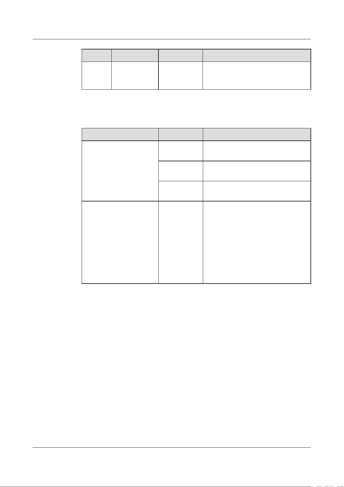
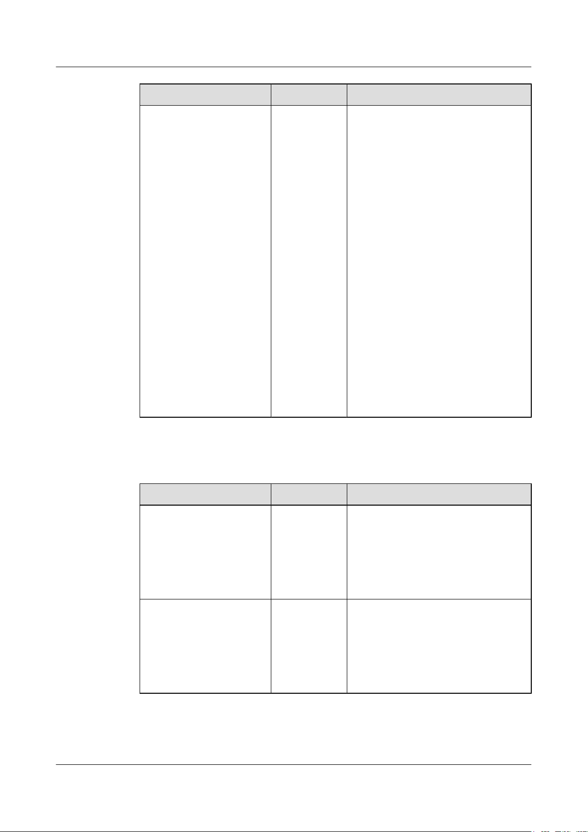
Table 2-15 Description of 10GE service port indicators in different modes (two indicators for
each port)
Mode Color Description
Status - Off: The port is not connected or has been
shut down.
Green Steady on: A link has been established on
the port.
Yellow Blinking: The port is sending or receiving
data.
Speed Green and
yellow
l Off: The port is not connected or has
been shut down.
l Both steady on:
1000M/10GE port: The port is
operating at 1000 Mbit/s.
l Green indicator steady on and yellow
indicator blinking:
1000M/10GE port: The port is
operating at 10 Gbit/s.
Issue 12 (2015-07-31) Huawei Proprietary and Confidential
Copyright © Huawei Technologies Co., Ltd.
34
Page 44
S6700 Series Ethernet Switches
Hardware Description
Mode Color Description
2 Chassis
Stack Green and
yellow
l Off: Port indicators do not show the
stack member ID of the switch.
l Both steady on:
The switch is not the master switch in
a stack.
– If the indicators of a service port are
steady on, the number of the service
port is the stack ID of the switch.
– If indicators of the first nine ports
are steady on, the stack ID of the
switch is 0.
l Green indicator steady on and yellow
indicator blinking:
The switch is the master switch in a
stack.
– If the indicators of a service port are
blinking, the number of the service
port is the stack ID of the switch.
– If indicators of the first nine ports
are blinking, the stack ID of the
switch is 0.
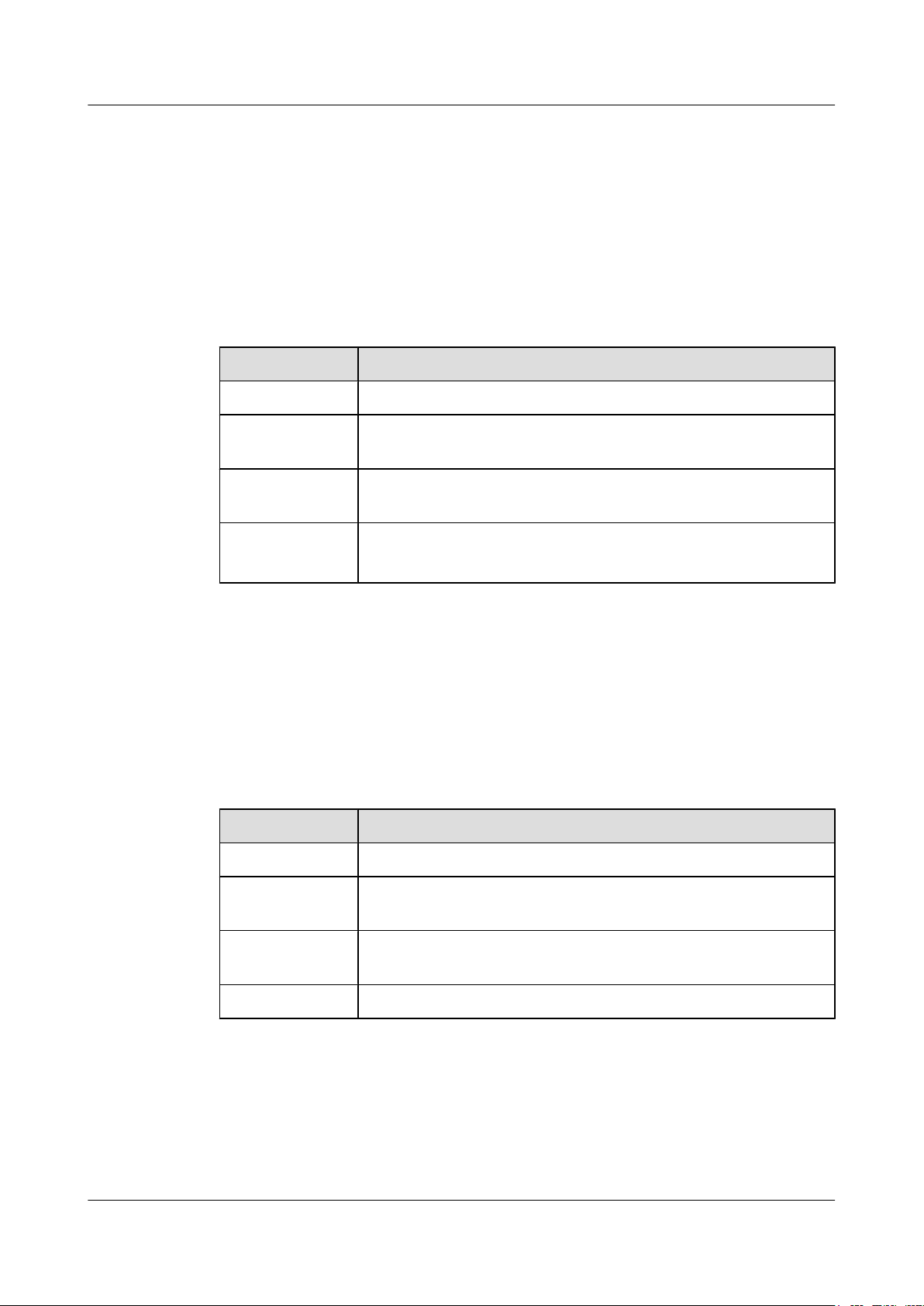
Table 2-16 Description of 40GE service port indicators in different modes (one indicator for
each port)
Display Mode Color Description
Status Green
l Off: The port is not connected or has
been shut down.
l Steady on: A link has been established
on the port.
l Blinking: The port is sending or
receiving data.
Speed Green
l Off: The port is not connected or has
been shut down.
l Steady on: The port is operating at 10
Gbit/s.
l Blinking: The port is operating at 40
Gbit/s.
Issue 12 (2015-07-31) Huawei Proprietary and Confidential
Copyright © Huawei Technologies Co., Ltd.
35
Page 45
S6700 Series Ethernet Switches
Hardware Description
2.5.4 Port Description
10GE SFP+ Ethernet Optical Port
A 10GE SFP+ Ethernet optical port supports auto-sensing to 1000 Mbit/s. It sends and receives
service data at 1000 Mbit/s or 10 Gbit/s. Table 2-17 describes the attributes of a 10GE SFP+
Ethernet optical port.
Table 2-17 Attributes of a 10GE SFP+ Ethernet optical port
Attribute Description
Connector type LC/PC
2 Chassis
Optical port
attributes
Standards
compliance
Working mode GE/10GE auto-sensing
Depend on the optical module used (see SFP/eSFP Modules and SFP
+ Modules)
IEEE802.3ae
Full-duplex
40GE QSFP+ Ethernet Optical Port
A 40GE QSFP+ optical port sends and receives service traffic at 40 Gbit/s and can be split into
four 10GE ports. After a split, 40GE QSFP+ optical port needs to be connected to a remote
device using a 1-to-4 QSFP+ fiber (with matching optical modules) or a 1-to-4 QSFP+ copper
cable. Table 2-18 describes the attributes of a 40GE QSFP+ optical port.
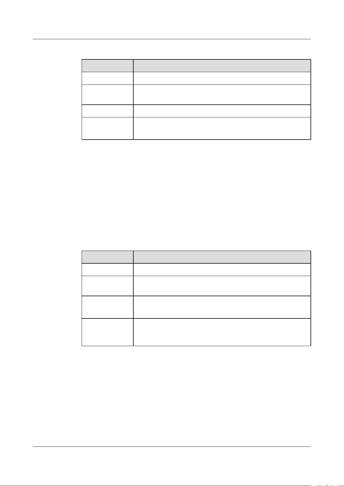
Table 2-18 Attributes of a 40GE QSFP+ optical port
Attribute Description
Connector type MPO/LC
Optical port
attributes
Standards
compliance
Working mode Full-duplex
Depend on the optical module used (see QSFP+ Modules)
IEEE802.3ba
Console Port
The console port is connected to a console for on-site configuration. The port must use a console
cable. The console port is used when a switch is powered on for the first time. For details about
the attributes of a console port, see Table 2-19.
Issue 12 (2015-07-31) Huawei Proprietary and Confidential
Copyright © Huawei Technologies Co., Ltd.
36
Page 46
S6700 Series Ethernet Switches
Hardware Description
Table 2-19 Attributes of a console port
Attribute Description
Connector type RJ45
2 Chassis
Standards
compliance
Working mode Duplex Universal Asynchronous Receiver/Transmitter (UART)
Baud rate 9600 bit/s, 19200 bit/s, 38400 bit/s, 57600 bit/s, or 115200 bit/s
ETH Management Port
You can connect a switch to a configuration terminal or network management workstation
through the ETH management port to configure the switch locally or remotely. The port must
use a network cable. You can choose to download the software package through the ETH
management port in the BootLoad menu. File transfer through the ETH management port is
faster than transfer through the console port. For details on how to use the ETH management
port, see the Configuration Guide - Basic Configurations. Table 2-20 describes the attributes
of an ETH management port.
Table 2-20 Attributes of an ETH management port
Attribute Description
RS-232
Default value: 9600 bit/s
Connector type RJ45
Standards
compliance
Working mode 10/100 Mbit/s auto-sensing
Maximum
transmission
distance
IEEE802.3
Full duplex
100 m
USB Port
The USB port can have a USB flash drive connected to upgrade the switch, or transfer
configuration files or other files. The USB flash drive used on an S6720-EI switch must support
USB 1.1 or USB 2.0 and be compatible with the Linux operating system.
2.5.5 Power Supply Configuration
Issue 12 (2015-07-31) Huawei Proprietary and Confidential
Copyright © Huawei Technologies Co., Ltd.
37
Page 47
PWR2
NEG RTN
Motherboard
GND12V
PWR1
NEG RTN
PWR2
L N
Motherboard
GND12V
PGND
PWR1
L N PGND
S6700 Series Ethernet Switches
Hardware Description
S6720-EI Power Supply Configuration
An S6720-EI switch can have one or two power modules installed.
When a switch has two power modules installed, the two power modules work in 1+1 redundancy
mode. AC and DC power modules can be used together in the same switch.
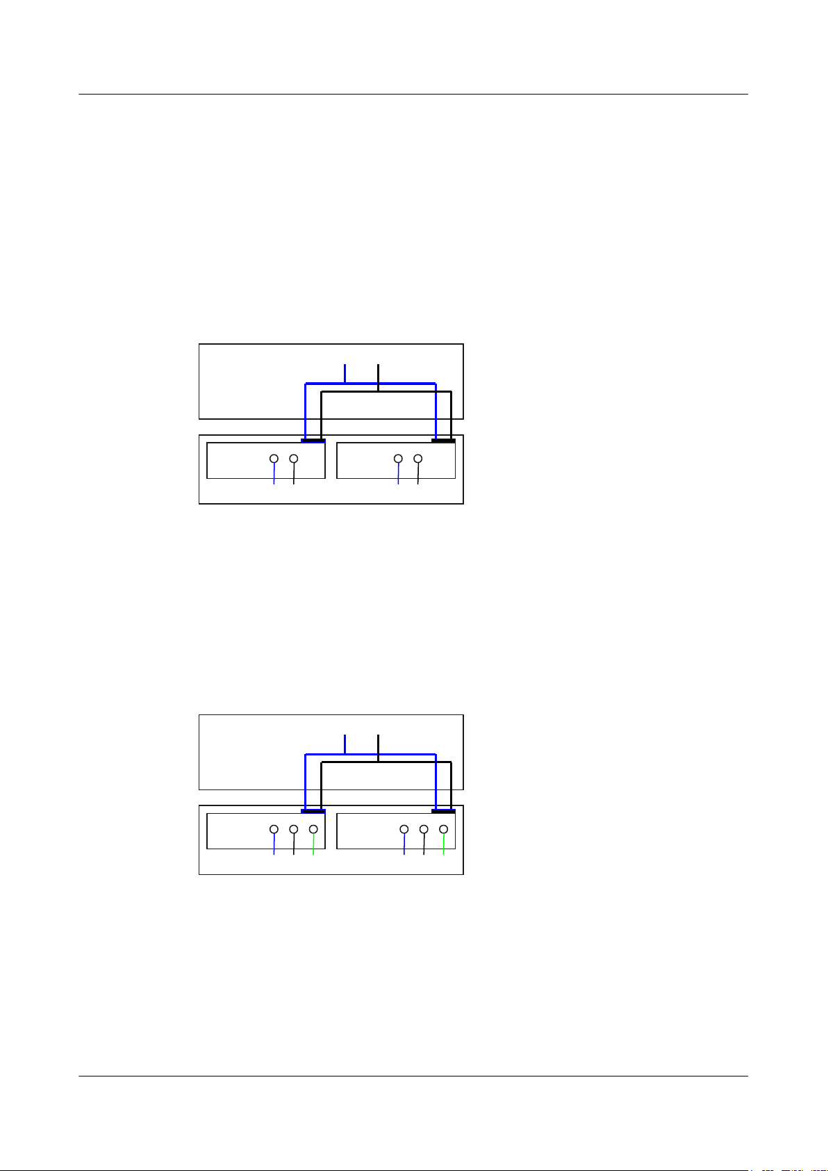
Figure 2-11 shows the power supply connections of dual DC power modules. After DC power
is transmitted to the PWR module, the PWR module provides 12 V output voltage, and the
motherboard provides power for the entire device.
Figure 2-11 Power supply connections of dual DC power modules
2 Chassis
NEG: Negative cable
RTN: Positive cable GND: 12 V reference ground
Figure 2-12 shows the power supply connections of dual non-PoE AC power modules. After
AC power is transmitted to the PWR module, the PWR module provides 12 V output voltage,
and the motherboard provides power for the entire device.
Figure 2-12 Power supply connections of dual non-PoE AC power modules
L: Live wire
N: Neutral wire PGND: Protective ground wire GND: 12 V reference ground
2.5.6 Heat Dissipation
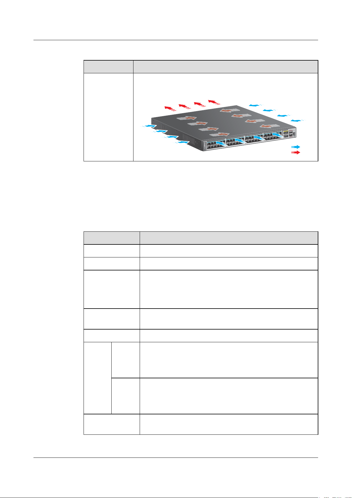
Table 2-21 lists the heat dissipation method of the S6720-EI series switches.
Issue 12 (2015-07-31) Huawei Proprietary and Confidential
Copyright © Huawei Technologies Co., Ltd.
38
Page 48
1
2
3
4
5
6
7
8
9
10
11
12
13
14
15
16
17
18
19
20
21
22
23
24
25
26
27
28
29
30
31
32
33
34
35
36
37
38
39
40
41
42
43
44
45
46
47
48
MODE
S6720-54C-EI-48S
1
2
CONSOLE
ETH
Cold air
Hot air
S6700 Series Ethernet Switches
Hardware Description 2 Chassis
Table 2-21 S6720-EI heat dissipation method
Model Heat Dissipation Method
l S6720-30C-
EI-24S-AC
l S6720-54C-
EI-48S-AC
2.5.7 Specifications
Table 2-22 lists specifications of the S6720-EI series switches.
Table 2-22 Specifications of the S6720-EI series switches
Item Description
Memory (RAM) 2 GB
Forcible heat dissipation
The air flows in from the left, right, and front, and flows out from the rear
panel.
Flash 240 MB
Mean time between
failures (MTBF)
l S6720-30C-EI-24S-AC: 80.60 years without card; 70.79 years
when a 4x40GE QSFP+ card is configured
l S6720-54C-EI-48S-AC: 79.39 years without card; 69.86 years
when a 4x40GE QSFP+ card is configured
Mean time to repair
2 hours
(MTTR)
Availability > 0.99999
Surge
protecti
on
Service
port
protectio
-
n
Power
supply
l AC models: ±6 kV in differential mode; ±6 kV in common mode
l DC models: ±1 kV in differential mode; ±2 kV in common mode
protectio
n
Dimensions (W x D
442.0 mm x 420.0 mm x 43.6 mm
x H)
Issue 12 (2015-07-31) Huawei Proprietary and Confidential
Copyright © Huawei Technologies Co., Ltd.
39
Page 49
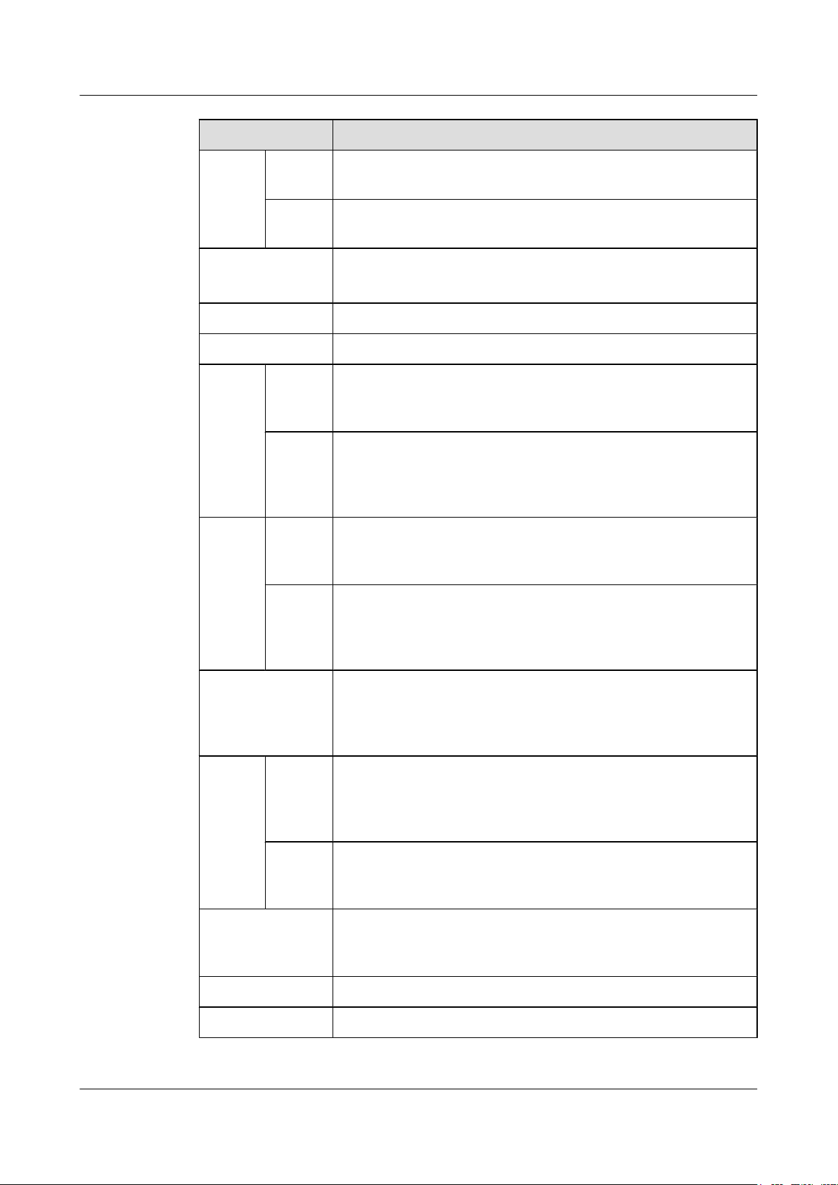
S6700 Series Ethernet Switches
Hardware Description 2 Chassis
Item Description
Weight Fully
≤ 12 kg
loaded
Empty
≤ 8 kg
chassis
Stack port
l Any 10GE SFP+ ports (a maximum of 16 physical ports)
l Any 40GE QSFP+ ports (a maximum of 6 physical ports)
RPS Not supported
PoE Not supported
DC
input
voltage
Rated
voltage
range
Maximu
-48 V DC to -60 V DC
-38.4 V DC to -72 V DC
m
voltage
range
AC
input
voltage
Rated
voltage
range
100 V AC to 240 V AC, 50/60 Hz
Maximu
90 V AC to 264 V AC, 47 Hz to 63 Hz
m
voltage
range
Maximum power
consumption (100%
l S6720-30C-EI-24S-AC: 233.7 W
l S6720-54C-EI-48S-AC: 296.1 W
throughput, full
speed of fans)
Temper
ature
Operatin
g
temperat
ure
Storage
0°C-45°C (at altitude of 0-1800 m)
NOTE
When the altitude is between 1800 m and 5000 m, the operating temperature
reduces by 1°C every time the altitude increases by 220 m.
-40°C to +70°C
temperat
ure
Noise under normal
Less than 72.1 dBA
temperature (27°C,
sound power)
Relative humidity 5% RH to 95% RH, noncondensing
Operating altitude 0 m to 5000 m
Issue 12 (2015-07-31) Huawei Proprietary and Confidential
Copyright © Huawei Technologies Co., Ltd.
40
Page 50

S6700 Series Ethernet Switches
Hardware Description 2 Chassis
Item Description
Certification
l EMC certification
l Safety certification
l Manufacturing certification
Issue 12 (2015-07-31) Huawei Proprietary and Confidential
Copyright © Huawei Technologies Co., Ltd.
41
Page 51

S6700 Series Ethernet Switches
Hardware Description
About This Chapter
3 Power Modules
3 Power Modules
NOTICE
l All power modules are hot swappable, but it is highly recommended that you power off a
switch before removing or installing a power module in the switch to protect personal and
equipment safety.
l Before replacing a power module in a switch, make sure that the switch can be powered by
the other power module after the power module is removed. Otherwise, services on the
switches will be interrupted by a power failure when the power module is removed.
l Before powering off a switch, shut down all of its power supply units.
l The S6720-EI can use 350 W DC and 600 W AC power modules together. Other models do
not allow power modules of different power values to be used in the same chassis.
3.1 350 W DC power module
3.2 500 W DC Power Module
3.3 600 W AC Power Module
3.4 500 W AC Power Module
Issue 12 (2015-07-31) Huawei Proprietary and Confidential
Copyright © Huawei Technologies Co., Ltd.
42
Page 52
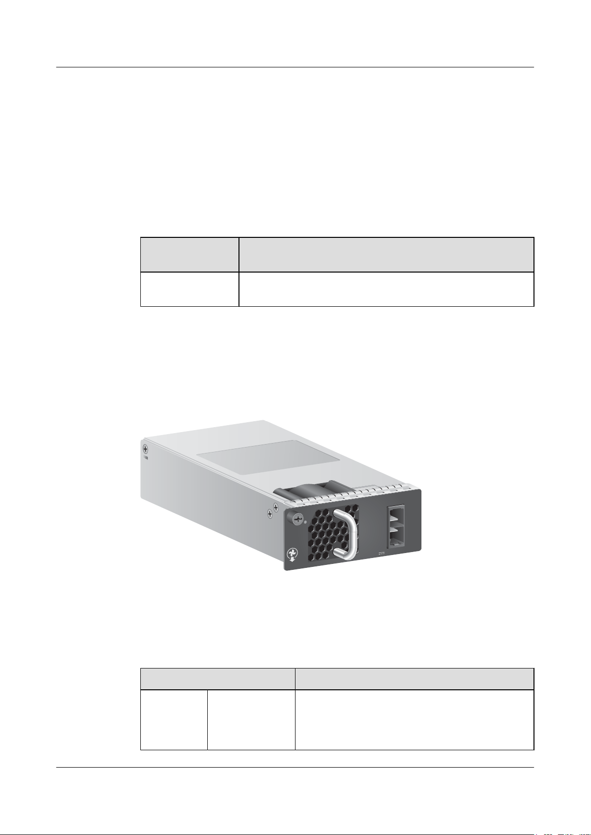
PDC-350WA-B
-48 -60V ; 11A
RTN(+)
NEG(-)
STATUS
S6700 Series Ethernet Switches
Hardware Description 3 Power Modules
3.1 350 W DC power module
Product Support
Table 3-1 lists the switch chassis matching a 350 W DC power module.
Table 3-1 Switch chassis matching a 350 W DC power module
Appearance
Power Module
Product Support
Name
PDC-350WA-B Supported only in the S6720-30C-EI-24S-AC and S6720-54C-
EI-48S-AC
Figure 3-1 shows the appearance of a 350 W DC power module.
Figure 3-1 Appearance of a 350 W DC power module
Function
Table 3-2 describes the functions of a 350 W DC power module.
Table 3-2 Functions of a 350 W DC power module
Function Description
Input
protection
Issue 12 (2015-07-31) Huawei Proprietary and Confidential
Input
undervoltage
protection
In this protection state, the power module stops
supplying power. When the input voltage restores to the
normal range, the power module automatically resumes
power supply.
Copyright © Huawei Technologies Co., Ltd.
43
Page 53
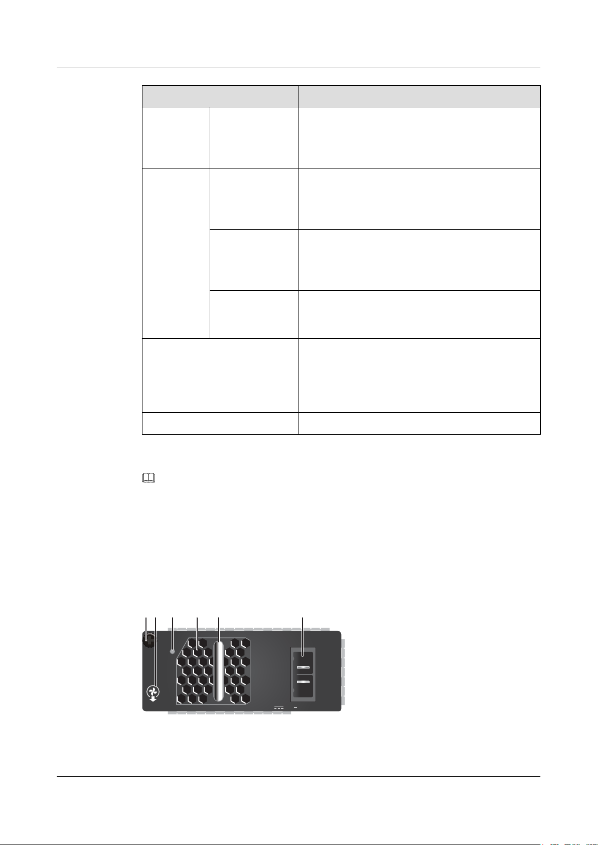
-48 -60V ; 11A
RTN(+)
NEG(-)
STATUS
PDC-350WA-B
2 314 5 6
S6700 Series Ethernet Switches
Hardware Description 3 Power Modules
Function Description
Input overcurrent
protection
In this protection state, the power module stops
supplying power and cannot automatically resume
power supply when the input current restores to the
normal range.
Output
protection
Output
overvoltage
protection
In this protection state, the power module stops
supplying power intermittently. When the system
recovers from output overvoltage, the power module
automatically resumes power supply.
Output
overcurrent
protection
In this protection state, the power module supplies
power intermittently. When the output current is within
a range, the power module automatically resumes power
supply.
Output shortcircuit protection
In this protection state, the power module supplies
power intermittently. When the short circuit is removed,
the power module automatically resumes power supply.
Overtemperature protection When the temperature of the power module exceeds a
specified threshold, the power module stops supplying
power. When the temperature falls into the normal
range, the power module automatically resumes power
supply.
Panel
Hot swap Supported
NOTE
When a power module enters overtemperature protection state, take measures to lower the ambient
temperature. The power module can automatically resume power supply when the temperature falls within
the normal range.
Figure 3-2 shows the panel of a 350 W DC power module.
Figure 3-2 Panel of a 350 W DC power module
Issue 12 (2015-07-31) Huawei Proprietary and Confidential
44
Copyright © Huawei Technologies Co., Ltd.
Page 54
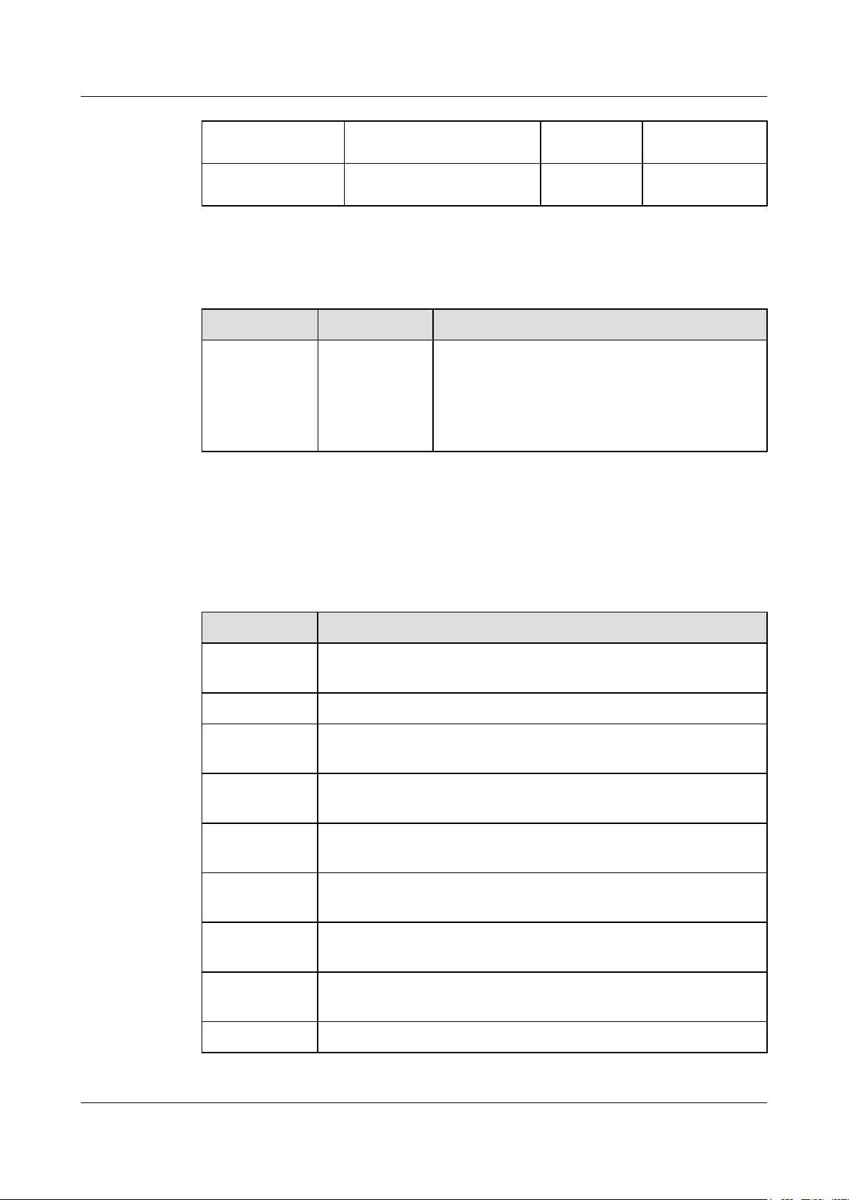
S6700 Series Ethernet Switches
Hardware Description
1. Captive screw 2. Airflow flag (air out) 3. Indicator 4. Fan air vent
3 Power Modules
Specifications
5. Handle 6. DC power socket
- -
Table 3-3 describes the indicator on the 350 W DC power module panel.
Table 3-3 Description of the indicator on the 350 W DC power module panel
Indicator Color Description
STATUS:
running status
indicator
Green
l Off: The power input is abnormal (for example, no
input, overvoltage, or undervoltage) or the power
output is abnormal (for example, overvoltage,
overcurrent, short-circuit, or overtemperature).
l Steady on: The power module is working normally.
Table 3-4 describes technical specifications of a 350 W DC power module.
Table 3-4 Specifications of a 350 W DC power module
Item Description
Dimensions (W
100 mm x 205 mm x 40 mm
x D x H)
Weight 0.72 kg
Rated input
-48 V DC to -60 V DC
voltage range
Maximum input
-38.4 V DC to -72 V DC
voltage
Maximum input
11 A
current
Maximum
29.17 A
output current
Rated output
12 V
voltage
Rated output
350 W
power
Part number 02310PQN
Issue 12 (2015-07-31) Huawei Proprietary and Confidential
Copyright © Huawei Technologies Co., Ltd.
45
Page 55
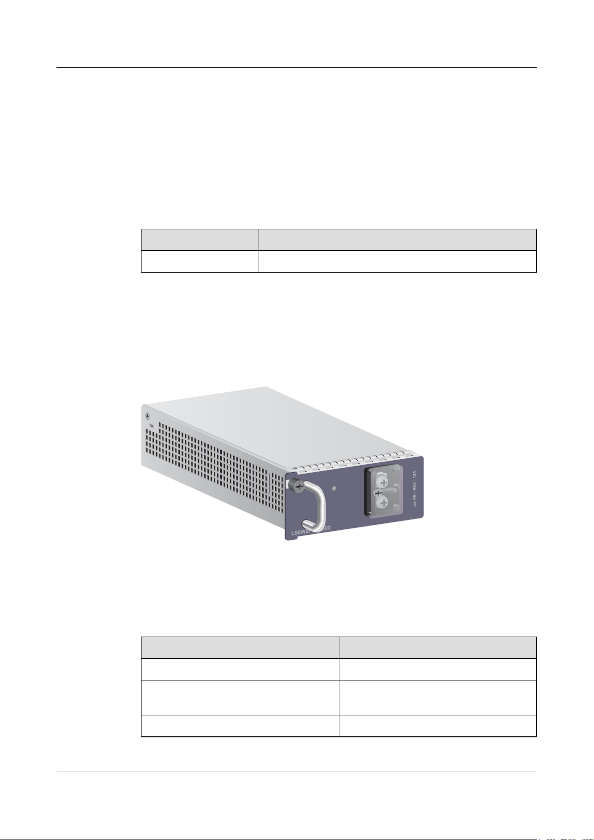
STATUS
NEG(-) RTN(+)
S6700 Series Ethernet Switches
Hardware Description
3.2 500 W DC Power Module
Version Mapping
Table 3-5 lists the switch chassis and software versions matching a 500 W DC power module.
Table 3-5 Switch chassis and software versions matching a 500 W DC power module
Power Module Name Product Support
LS6W2PSD0500 Supported only in the S6700-24-EI and S6700-48-EI
Appearance
3 Power Modules
Function
Figure 3-3 shows the appearance of a 500 W DC power module.
Figure 3-3 Appearance of the 500 W DC power module
Table 3-6 describes the functions of a 500 W DC power module.
Table 3-6 Functions of a 500 W DC power module
Function Description
Input protection Input power detection is provided.
Output protection Output overcurrent and short-circuit
protection is provided.
Surge protection -
Issue 12 (2015-07-31) Huawei Proprietary and Confidential
Copyright © Huawei Technologies Co., Ltd.
46
Page 56
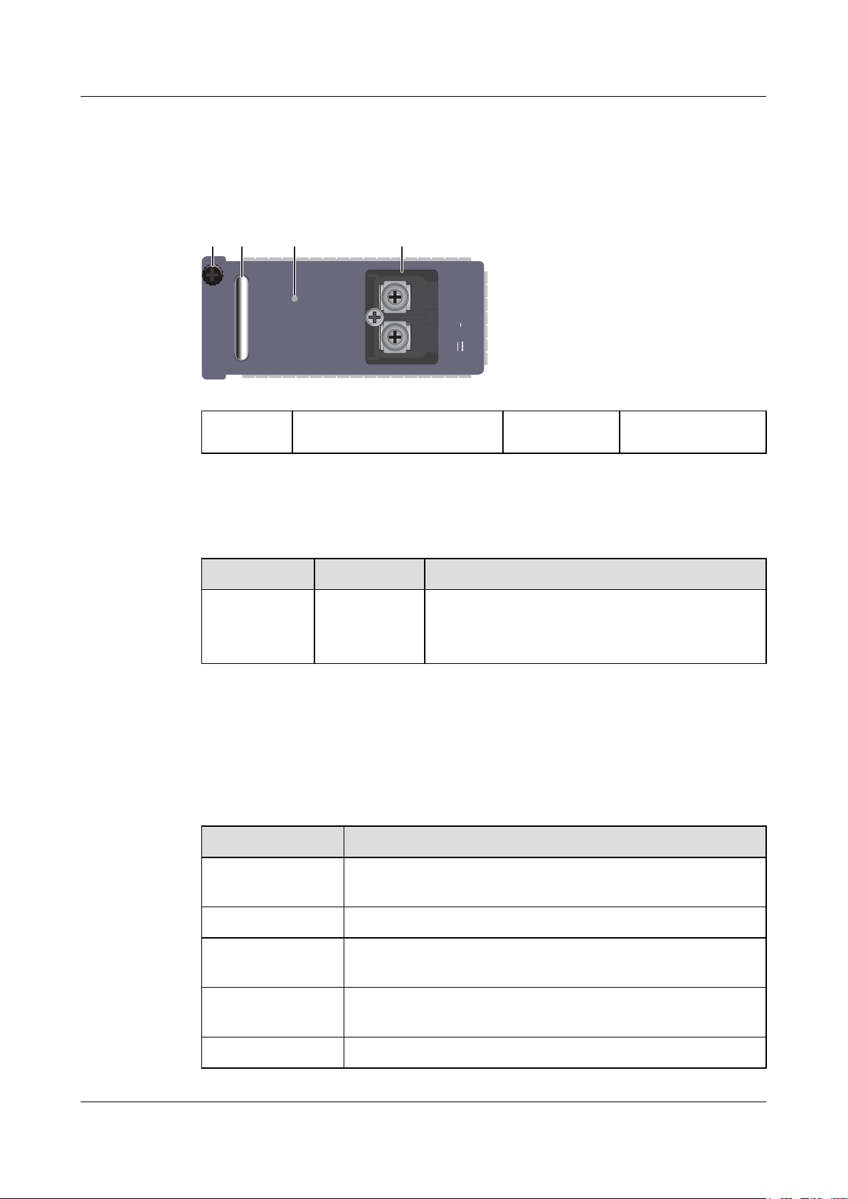
STATUS
LS6W2PSD0500
NEG(-) RTN(+)
-48 -60V ; 13A
14 2 3
S6700 Series Ethernet Switches
Hardware Description 3 Power Modules
Panel Description
Figure 3-4 shows the panel of a 500 W DC power module.
Figure 3-4 Panel of a 500 W DC power module
1. Handle 2. Power status indicator 3. DC socket 4. Captive screw
Specifications
Table 3-7 describes indicators on a 500 W DC power module panel.
Table 3-7 Description of indicators on a 500 W DC power module panel
Indicator Color Description
STATUS Green
l Off: No DC power input is provided.
l Steady on: The DC input power is in the normal
range.
Table 3-8 describes technical specifications of a 500 W DC power module.
Table 3-8 Technical specifications of a 500 W DC power module
Item Description
Dimensions (W x D xH)100 mm x 205 mm x 40 mm
Issue 12 (2015-07-31) Huawei Proprietary and Confidential
Weight 1 kg
Rated input voltage
-48 V DC to -60 V DC
range
Maximum input
-38.4 V DC to -72 V DC
voltage range
Input current 13 A
Copyright © Huawei Technologies Co., Ltd.
47
Page 57
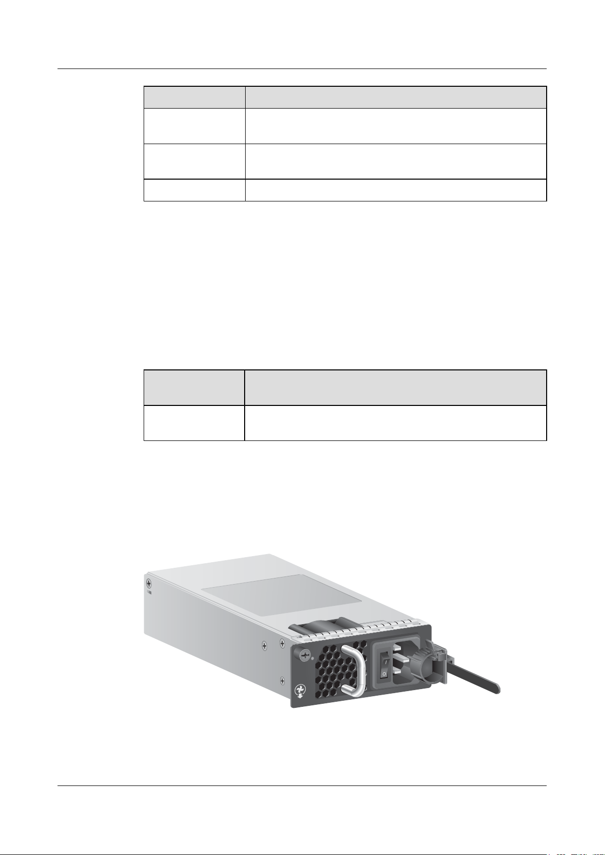
PAC-600WA-B
STATUS
~100-240V;50/60 Hz;9A
S6700 Series Ethernet Switches
Hardware Description
Item Description
3 Power Modules
Maximum output
13 A
current
Maximum output
500 W
power
Part number 02310JWV
3.3 600 W AC Power Module
Product Support
Table 3-9 lists the switch chassis matching a 600 W AC power module.
Table 3-9 Switch chassis matching a 600 W AC power module
Power Module
Name
Product Support
Appearance
PAC-600WA-B Supported only in the S6720-30C-EI-24S-AC and S6720-54C-
EI-48S-AC
Figure 3-5 shows the appearance of a 600 W AC power module.
Figure 3-5 Appearance of a 600 W AC power module
Function
Table 3-10 describes the functions of a 600 W AC power module.
Issue 12 (2015-07-31) Huawei Proprietary and Confidential
Copyright © Huawei Technologies Co., Ltd.
48
Page 58
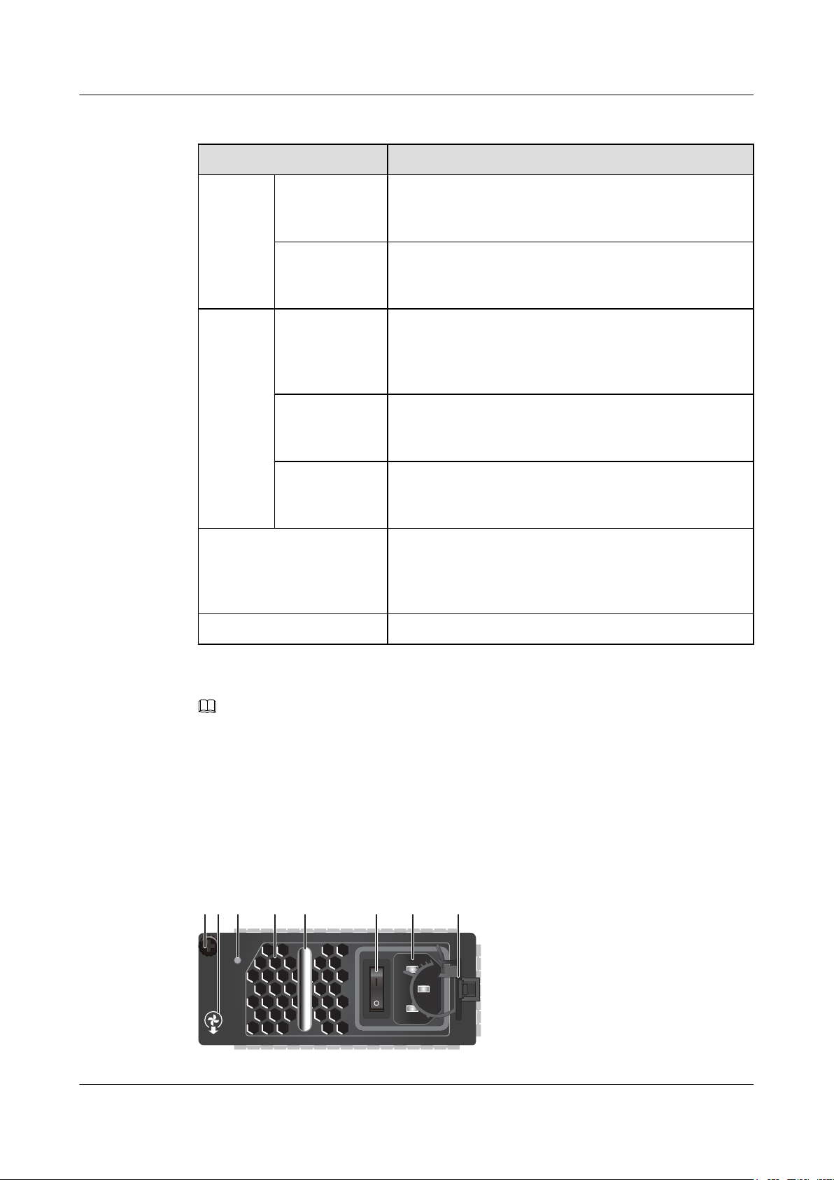
~100-240V;50/60 Hz;9A
STATUS
PAC-600WA-B
213 4 5 6 7 8
S6700 Series Ethernet Switches
Hardware Description
Table 3-10 Functions of a 600 W AC power module
Function Description
3 Power Modules
Input
protection
Output
protection
Input
undervoltage
protection
Input
overcurrent
protection
Output
overvoltage
protection
In this protection state, the power module stops supplying
power. When the input voltage restores to the normal range,
the power module automatically resumes power supply.
In this protection state, the power module stops supplying
power and cannot automatically resume power supply when
the input current restores to the normal range.
In this protection state, the power module stops supplying
power intermittently. When the system recovers from output
overvoltage, the power module automatically resumes power
supply.
Output
overcurrent
protection
Output shortcircuit
protection
In this protection state, the power module supplies power
intermittently. When the output current is within a range, the
power module automatically resumes power supply.
In this protection state, the power module supplies power
intermittently. When the short circuit is removed, the power
module automatically resumes power supply.
Overtemperature protection When the temperature of the power module exceeds a
specified threshold, the power module stops supplying
power. When the temperature falls into the normal range, the
power module automatically resumes power supply.
Panel
Hot swap Supported
NOTE
When a power module enters overtemperature protection state, take measures to lower the ambient
temperature. The power module can automatically resume power supply when the temperature falls within
the normal range.
Figure 3-6 shows the panel of a 600 W AC power module.
Figure 3-6 Panel of a 600 W AC power module
Issue 12 (2015-07-31) Huawei Proprietary and Confidential
49
Copyright © Huawei Technologies Co., Ltd.
Page 59
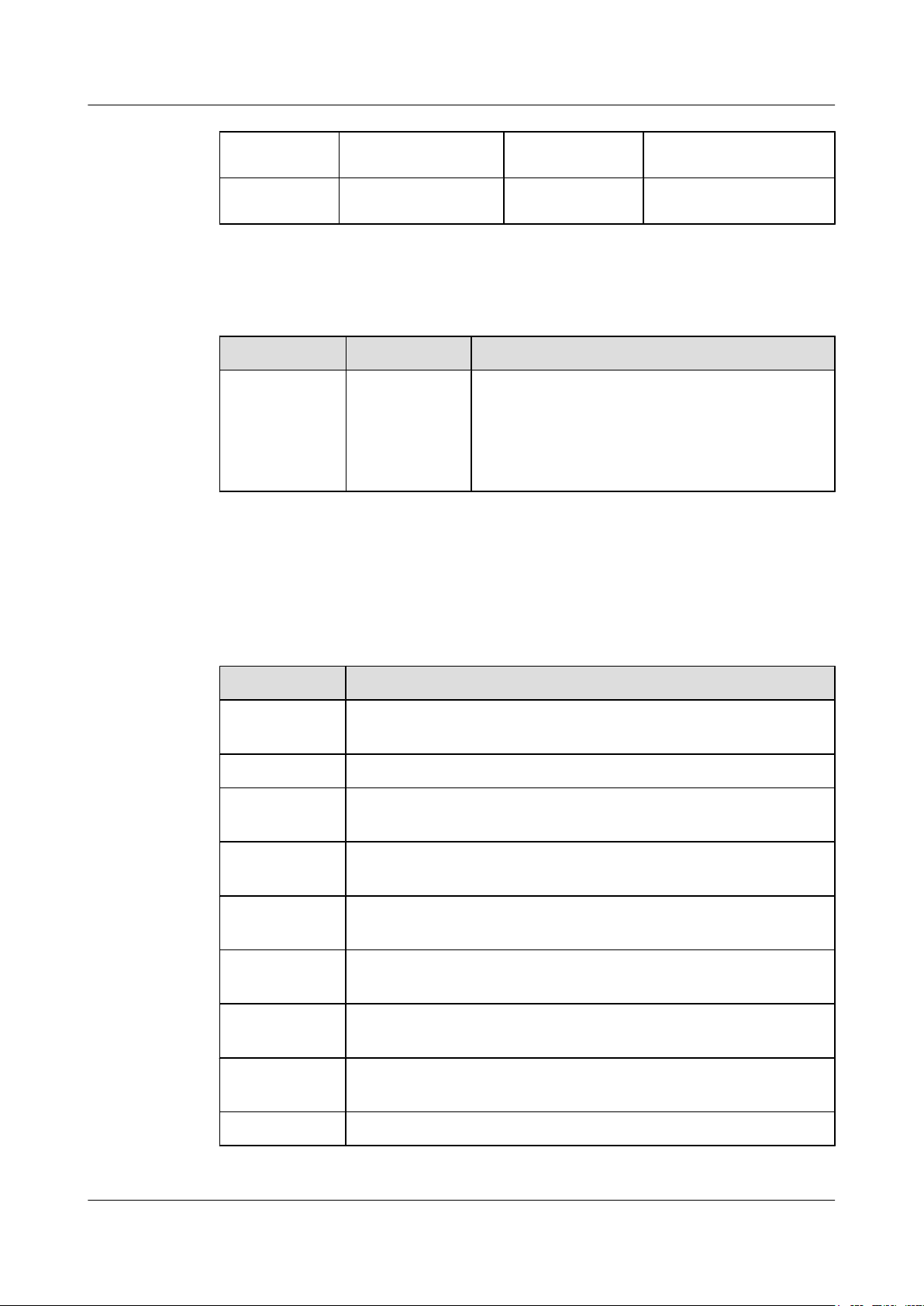
S6700 Series Ethernet Switches
Hardware Description
1. Captive screw 2. Airflow flag (air out) 3. Indicator 4. Fan air vent
5. Handle 6. Power switch 7. AC power socket 8. AC terminal locking latch
Table 3-11 describes the indicator on the 600 W AC power module panel.
Table 3-11 Description of the indicator on the 600 W AC power module panel
Indicator Color Description
3 Power Modules
Specifications
STATUS:
running status
indicator
Green
l Off: The power input is abnormal (for example, no
input, overvoltage, or undervoltage) or the power
output is abnormal (for example, overvoltage,
overcurrent, short-circuit, or overtemperature).
l Steady on: The power module is working normally.
Table 3-12 lists specifications of a 600 W AC power module.
Table 3-12 Specifications of a 600 W AC power module
Item Description
Dimensions (W
100 mm x 205 mm x 40 mm
x D x H)
Weight 1 kg
Rated input
100 V AC to 240 V AC, 50/60 Hz
voltage range
Maximum input
90 V AC to 290 V AC, 45 Hz to 65 Hz
voltage
Maximum input
9 A
current
Maximum
50 A
output current
Rated output
12 V
voltage
Rated output
600 W
power
Part number 02310PMH
Issue 12 (2015-07-31) Huawei Proprietary and Confidential
Copyright © Huawei Technologies Co., Ltd.
50
Page 60
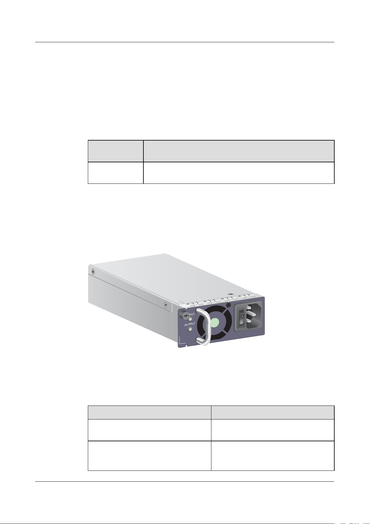
100-240Vac 50/60Hz 7-3.5A
S6700 Series Ethernet Switches
Hardware Description 3 Power Modules
3.4 500 W AC Power Module
Product Support
Table 3-13 lists the switch chassis matching a 500 W AC power modules.
Table 3-13 Switch chassis matching a 500 W AC power module
Appearance
Power Module
Name
W0PSA5000
(purplish grey)
Figure 3-7 shows the appearance of a W0PSA5000.
Figure 3-7 Appearance of a 500 W AC power module (W0PSA5000)
Product Support
Supported only in the S6700-24-EI and S6700-48-EI
Function
Table 3-14 describes the functions of a 500 W AC power module.
Table 3-14 Functions of a 500 W AC power module
Function Description
Input protection Input overcurrent and undervoltage
protection is provided.
Output protection Output undervoltage, overvoltage,
overcurrent, and short-circuit protection is
provided.
Issue 12 (2015-07-31) Huawei Proprietary and Confidential
Copyright © Huawei Technologies Co., Ltd.
51
Page 61
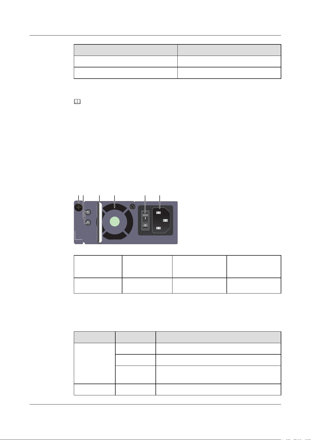
INPUT
OUTPUT
100-240Vac 50/60Hz 7-3.5A
21 3 4 56
S6700 Series Ethernet Switches
Hardware Description 3 Power Modules
Function Description
Overtemperature protection -
Surge protection -
NOTE
When a power module enters overtemperature protection state, take measures to lower the ambient
temperature. The power module can automatically resume power supply when the temperature falls within
the normal range.
The 500 W AC power supply on the S6700-EI is a PoE power supply. However, it can only be used as a
system power supply on the S6700-EI and cannot provide PoE function.
Panel Description
Figure 3-8 shows the panel of a W0PSA5000.
Figure 3-8 Panel of a 500 W AC power module (W0PSA5000)
1. Power status
2. Handle 3. Fan 4. Switch
indicator
5. AC power socket 6. Captive screw
- -
Table 3-15 describes indicators on a 500 W AC power module panel.
Table 3-15 Description of indicators on a 500 W AC power module panel
Indicator Color Description
INPUT - Off: The power module receives no input power.
Green Steady on: The AC input power is in the normal range.
Red Steady on: The AC input power is out of range, for
example, undervoltage or overvoltage.
OUTPUT - Off: The power module has no output power.
Issue 12 (2015-07-31) Huawei Proprietary and Confidential
Copyright © Huawei Technologies Co., Ltd.
52
Page 62
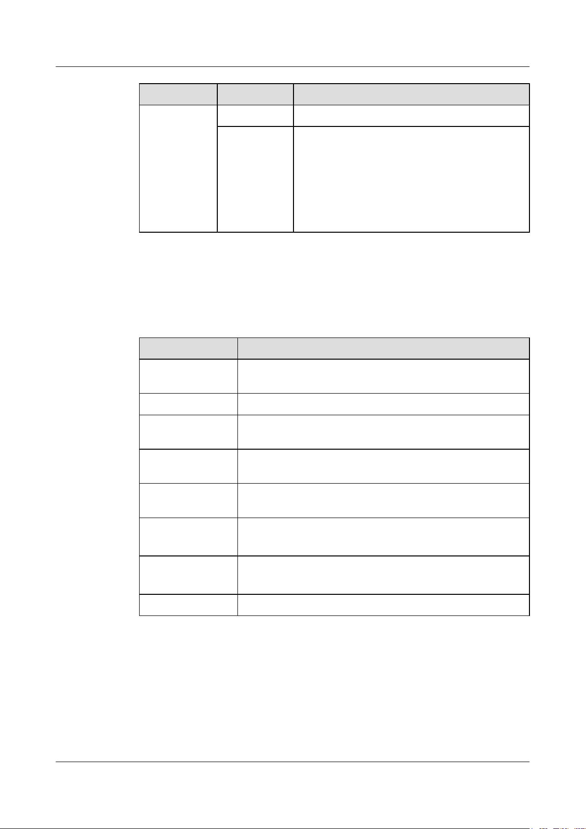
S6700 Series Ethernet Switches
Hardware Description 3 Power Modules
Indicator Color Description
Green Steady on: The AC output power is in the normal range.
Red Steady on: The power output is out of range.
l Abnormal power fan operation
l Output overvoltage
l Output overcurrent
l Short circuit
l Overtemperature
Specifications
Table 3-16 describes technical specifications of a 500 W AC power module.
Table 3-16 Technical specifications of a 500 W AC power module
Item Description
Dimensions (W x D xH)100 mm x 205 mm x 40 mm
Weight 1.06 kg
Rated input voltage
range
Maximum input
voltage range
Maximum input
current
Maximum output
current
Maximum output
power
Part number 02130879
100 V AC to 240 V AC, 50/60 Hz
90 V AC to 264 V AC, 47 Hz to 63 Hz
7 A to 3.5 A
l +12 V: 10 A
l -53.5 V: 7.11 A
l +12 V: 120 W
l -53.5 V: 380 W
Issue 12 (2015-07-31) Huawei Proprietary and Confidential
Copyright © Huawei Technologies Co., Ltd.
53
Page 63

S6700 Series Ethernet Switches
Hardware Description 4 Fan Modules
4 Fan Modules
About This Chapter
4.1 CX7E1FANA Fan Module
4.2 FAN-060B-B Fan Module
Issue 12 (2015-07-31) Huawei Proprietary and Confidential
Copyright © Huawei Technologies Co., Ltd.
54
Page 64
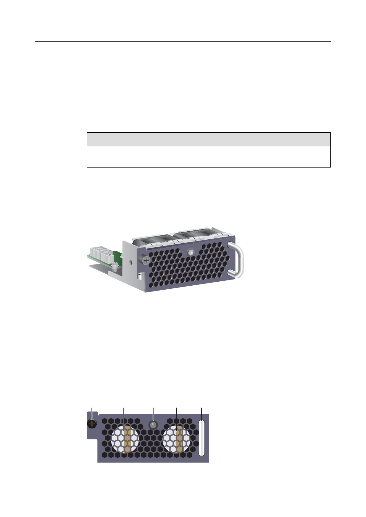
STATUS
STATUS
14 4 32
S6700 Series Ethernet Switches
Hardware Description
4.1 CX7E1FANA Fan Module
Product Support
Table 4-1 lists the switch chassis matching a CX7E1FANA fan module.
Table 4-1 Switch chassis matching a CX7E1FANA fan module
Fan Module Name Product Support
4 Fan Modules
Appearance
Function
CX7E1FANA fan
module
Figure 4-1 shows the appearance of a CX7E1FANA fan module.
Figure 4-1 Appearance of a CX7E1FANA fan module
Supported only in the S6700-24-EI and S6700-48-EI
Panel Description
Issue 12 (2015-07-31) Huawei Proprietary and Confidential
A CX7E1FANA fan module has two fans to cool the chassis. A CX7E1FANA fan module is
hot swappable.
Figure 4-2 shows the panel of a CX7E1FANA fan module.
Figure 4-2 Panel of a CX7E1FANA fan module
55
Copyright © Huawei Technologies Co., Ltd.
Page 65
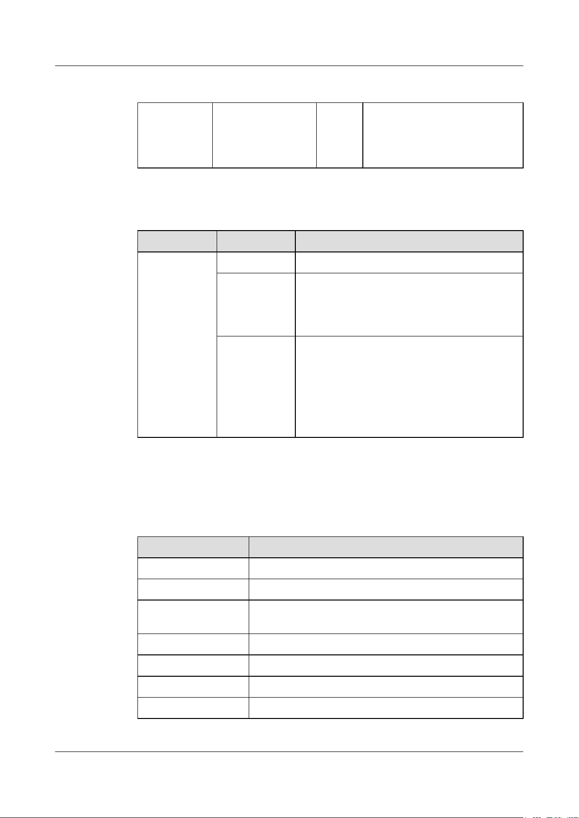
S6700 Series Ethernet Switches
Hardware Description
1. Captive screw 2. Fan module indicator 3. Handle 4. Two fans
Table 4-2 shows indicators on the CX7E1FANA fan module panel.
Table 4-2 Description of indicators on the CX7E1FANA fan module panel
Indicator Color Description
STATUS Off The fan module is not running.
4 Fan Modules
NOTE
Air is exhausted from air vents on the
panel.
Specifications
Green
l Slow blinking: The fan module is working properly
and its communication is normal.
l Fast blinking: The fan module is working properly
but its communication is abnormal.
Red
l Steady on: The fan module has a hardware fault
and needs to be replaced.
l Slow blinking: An alarm has been generated and
needs to be handled. Common causes of this alarm
include errors of dual in-line package (DIP)
switches, short-circuit, fan blades blocked, and
other fan module faults.
Table 4-3 describes technical specifications of a CX7E1FANA fan module.
Table 4-3 Technical specifications of a CX7E1FANA fan module
Item Description
Dimensions (W x D x H) 103 mm x 99.2 mm x 39.6 mm
Weight 250±20 g
Maximum power
12 W
consumption
Maximum wind pressure 375 Pa
Maximum wind rate 40 CFM
Operating voltage range 12 V DC
Part number 02351651
Issue 12 (2015-07-31) Huawei Proprietary and Confidential
Copyright © Huawei Technologies Co., Ltd.
56
Page 66
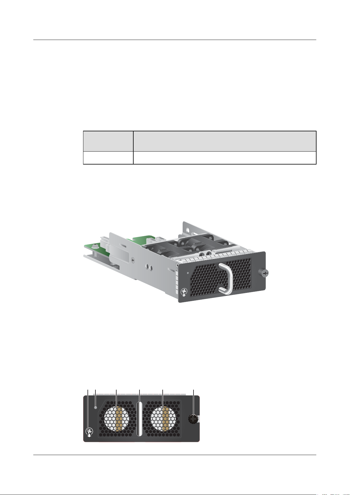
STATUS
FAN-060B-B
STATUS
FAN-060B-B
52 13 44
S6700 Series Ethernet Switches
Hardware Description
4.2 FAN-060B-B Fan Module
Version Mapping
Table 4-4 lists the switch chassis matching a FAN-060B-B fan module.
Table 4-4 Switch chassis matching a FAN-060B-B fan module
4 Fan Modules
Appearance
Fan Module
Product Support
Name
FAN-060B-B S6720-30C-EI-24S-AC and S6720-54C-EI-48S-AC
Figure 4-3 shows the appearance of a FAN-060B-B fan module.
Figure 4-3 Appearance of a FAN-060B-B fan module
Function
A FAN-060B-B fan module has two fans to cool the chassis. It is hot swappable.
Panel
Figure 4-4 shows the panel of a FAN-060B-B fan module.
Figure 4-4 Panel of a FAN-060B-B fan module
Issue 12 (2015-07-31) Huawei Proprietary and Confidential
Copyright © Huawei Technologies Co., Ltd.
57
Page 67
S6700 Series Ethernet Switches
Hardware Description 4 Fan Modules
1. Captive screw 2. Indicator 3. Handle 4. Two fans 5. Airflow flag (air out)
Table 4-5 describes the indicator on the FAN-060B-B fan module panel.
Table 4-5 Description of the indicator on the FAN-060B-B fan module panel
Indicator Color Meaning
Specifications
STATUS:
running status
indicator
Table 4-6 describes technical specifications of a FAN-060B-B fan module.
Table 4-6 Technical specifications of a FAN-060B-B fan module
Item Description
Dimension
s (W x D x
H)
Number of
fans
Off The fan module is not running.
Green Slow blinking: Fans are working properly.
Red Steady on: The fan module has a hardware fault and
must be replaced.
100 mm x 220 mm x 40 mm
2
Weight 0.4 kg
Maximum
power
consumpti
on
Maximum
fan speed
Maximum
wind rate
Part
number
Issue 12 (2015-07-31) Huawei Proprietary and Confidential
32.6 W
19000±10% rounds per minute (RPM)
64 cubic feet per minute (CFM)
02350DNQ
Copyright © Huawei Technologies Co., Ltd.
58
Page 68

S6700 Series Ethernet Switches
Hardware Description 5 Cards
5 Cards
About This Chapter
5.1 Introduction
5.2 ES5D21Q04Q01 (4-Port 40 Gig QSFP+ Rear Interface Card, Used in S6720-EI Series)
Issue 12 (2015-07-31) Huawei Proprietary and Confidential
Copyright © Huawei Technologies Co., Ltd.
59
Page 69
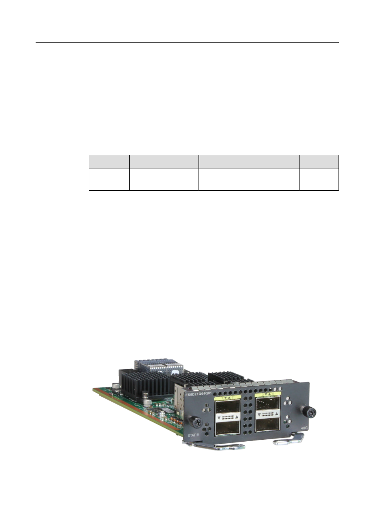
S6700 Series Ethernet Switches
Hardware Description
5.1 Introduction
5.1.1 Card Classification
Table 5-1 lists the card supported by the S6720-EI series switches.
Table 5-1 Card supported by the S6720-EI series switches
Card Type Card Name Card Description Hot Swap
5 Cards
Rear card ES5D21Q04Q01 4-port 40 Gig QSFP+ interface card
(used in S6720-EI)
Supported
5.2 ES5D21Q04Q01 (4-Port 40 Gig QSFP+ Rear Interface Card, Used in S6720-EI Series)
5.2.1 Introduction
The ES5D21Q04Q01 provides four 40GE QSFP+ optical ports to implement data access and
line-speed switching.
The ES5D21Q04Q01 can be installed in the rear card slot on the S6720-EI chassis.
Figure 5-1 shows the appearance of the ES5D21Q04Q01.
Figure 5-1 Appearance of the ES5D21Q04Q01
Issue 12 (2015-07-31) Huawei Proprietary and Confidential
Copyright © Huawei Technologies Co., Ltd.
60
Page 70
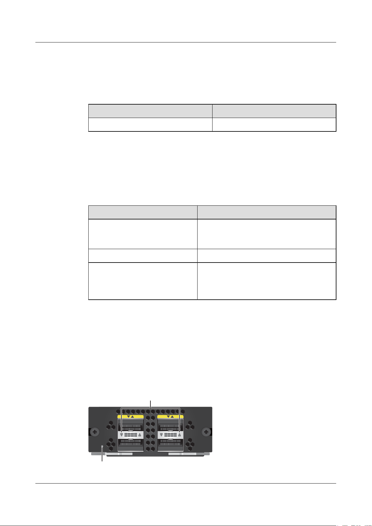
ES5D21Q04Q01
40G
STAT
12 34
1
2
S6700 Series Ethernet Switches
Hardware Description
5.2.2 Version Mapping
Table 5-2 lists the mapping between the ES5D21Q04Q01 and software versions.
Table 5-2 Mappings between the ES5D21Q04Q01 and software versions
Card Name Software Version
ES5D21Q04Q01 V200R008C00 and later versions
5.2.3 Functions and Features
Table 5-3 describes functions and features of the ES5D21Q04Q01.
Table 5-3 Functions and features of the ES5D21Q04Q01
5 Cards
Function and Feature Description
Basic functions Provides four 40GE QSFP+ optical ports to
Hot swap Supported
Service port stacking Ports on the card can be used as stack ports.
5.2.4 Indicators and Ports
Indicator Description
Figure 5-2 shows indicators on the ES5D21Q04Q01.
Figure 5-2 Indicators on the ES5D21Q04Q01
implement data access and line-speed switching.
Each 40GE port can be split into four 10GE ports.
NOTE
A 40GE port cannot be used as a stack port after it is split
into four 10GE ports.
Issue 12 (2015-07-31) Huawei Proprietary and Confidential
Copyright © Huawei Technologies Co., Ltd.
61
Page 71
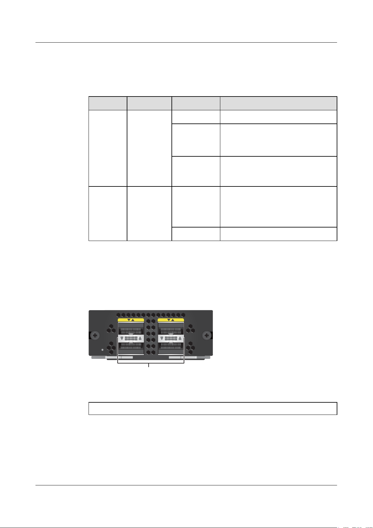
ES5D21Q04Q01
STAT
12 34
40G
1
S6700 Series Ethernet Switches
Hardware Description
Table 5-4 describes indicators on the ES5D21Q04Q01.
Table 5-4 Description of indicators on the ES5D21Q04Q01
Number Indicator Color Description
1 STAT Off The system software is not running.
5 Cards
Port Description
Figure 5-3 shows the ports on the ES5D21Q04Q01.
Figure 5-3 Ports on the ES5D21Q04Q01
Green
Red A fault that affects services has occurred.
2 ACT/LINK Green
Off No link is established on the port.
l Fast blinking: The system is starting.
l Slow blinking: The system is running
normally.
The fault cannot be rectified automatically
and requires manual intervention.
l Steady on: A link has been established
on the port.
l Blinking: The port is transmitting or
receiving data.
1. Four 40GE QSFP+ optical ports
40GE QSFP+ optical port
A 40GE QSFP+ optical port sends and receives service traffic at 40 Gbit/s and can be split into
four 10GE ports. After a split, 40GE QSFP+ optical port needs to be connected to a remote
device using a 1-to-4 QSFP+ fiber (with matching optical modules) or a 1-to-4 QSFP+ copper
cable. Table 5-5 lists the attributes of a 40GE QSFP+ optical port.
Issue 12 (2015-07-31) Huawei Proprietary and Confidential
Copyright © Huawei Technologies Co., Ltd.
62
Page 72
S6700 Series Ethernet Switches
Hardware Description 5 Cards
NOTE
All the optical ports on the ES5D21Q04Q01 support only QSFP+ optical modules and QSFP+ copper
cables.
Table 5-5 Attributes of a QSFP+ optical port
Attribute Description
Connector type LC/MPO
Optical port attributes Depend on the optical module used (see 7.4.3
QSFP+ Modules)
Standards compliance IEEE 802.3ba
5.2.5 Specifications
Table 5-6 lists specifications of the ES5D21Q04Q01.
Table 5-6 Specifications of the ES5D21Q04Q01
Item Description
Physical
specifications
Environment
parameters
l Dimensions (W x D x H): 100 mm x 208 mm x 40 mm
l Weight: 0.5 kg
l Maximum power consumption: 18.83 W
l Operating temperature: 0°C to 45°C
l Relative humidity: 5% RH to 95% RH
l Storage temperature: -40°C to +70°C
5.2.6 Ordering Information
Card ordering information is subject to updates with product version upgrades. The ordering
information provided in this manual is for reference only. To obtain latest ordering information,
contain Huawei switch distributors or Huawei local office.
Table 5-7 provides ES5D21Q04Q01 ordering information.
Table 5-7 ES5D21Q04Q01 ordering information
Card Description Card Name Part Number
4-port 40 Gig QSFP+
interface card
Issue 12 (2015-07-31) Huawei Proprietary and Confidential
Copyright © Huawei Technologies Co., Ltd.
ES5D21Q04Q01 03022RRP
63
Page 73

S6700 Series Ethernet Switches
Hardware Description 6 Cables
6 Cables
About This Chapter
6.1 Ground Cable
6.2 Optical Fiber
6.3 Network Cable
6.4 DC Power Cable (OT and Cord End Terminals)
6.5 DC Power Cable (Quick-Connect Cord End Terminal)
6.6 AC Power Cable
6.7 Console Cable
6.8 Copper Cable
Issue 12 (2015-07-31) Huawei Proprietary and Confidential
Copyright © Huawei Technologies Co., Ltd.
64
Page 74
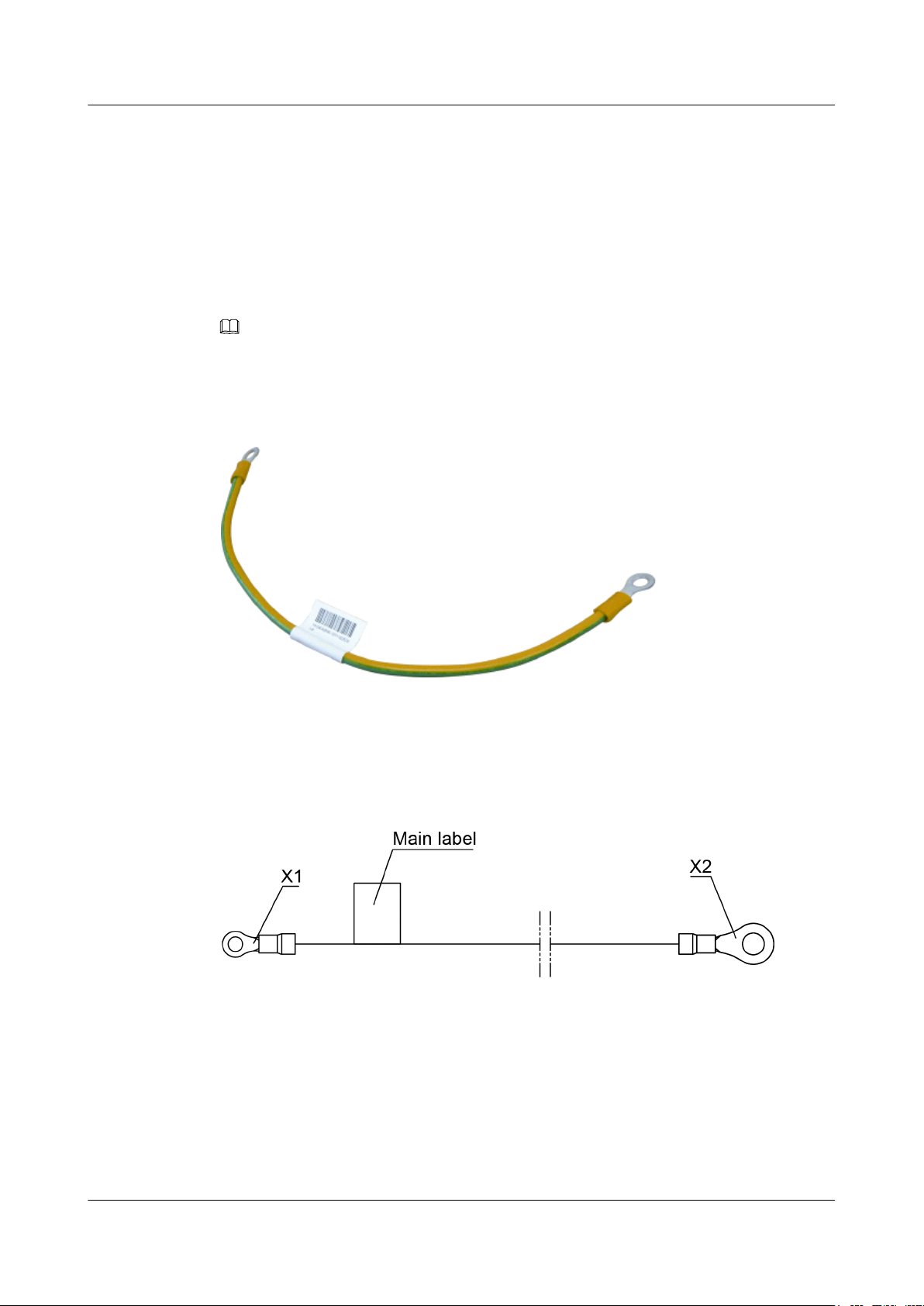
S6700 Series Ethernet Switches
Hardware Description
6.1 Ground Cable
Appearance and Structure
Figure 6-1 shows the appearance of a typical ground cable.
NOTE
Other types of ground cables are similar to the example shown in the figure, except for their cross-sectional
area, size of the cable lugs, and cable length.
Figure 6-1 Appearance of a ground cable
6 Cables
Figure 6-2 shows the structure of a ground cable.
Figure 6-2 Structure of a ground cable
Pin Assignments
Table 6-1 lists the pin assignments of a ground cable.
Issue 12 (2015-07-31) Huawei Proprietary and Confidential
Copyright © Huawei Technologies Co., Ltd.
65
Page 75
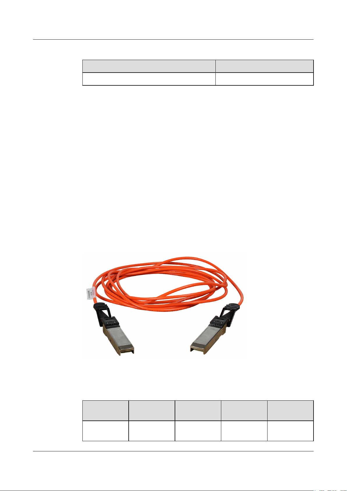
S6700 Series Ethernet Switches
Hardware Description 6 Cables
Table 6-1 Pin assignments of a ground cable
X1 X2
OT-4 OT-6
Connection
A ground cable grounds a device to protect it from lightning and electromagnetic interference.
A ground cable is connected to a chassis in the following way:
l The OT-4 naked crimping connector connects to the ground point on the chassis.
l The OT-6 naked crimping connector connects to the ground point on the cabinet.
6.2 Optical Fiber
Active Optical Cable
An active optical cable (AOC) is an optical fiber with optical modules at both ends, making it
easy to use. Figure 6-3 shows the appearance of an AOC cable.
Figure 6-3 Appearance of an AOC cable
Table 6-2 lists models and attributes of AOC cables.
Table 6-2 Attributes of AOC cables
Model Length Bend Radius Connector
SFP-10GAOC3M
Issue 12 (2015-07-31) Huawei Proprietary and Confidential
3 m 30 mm SFP+ 0°C to 70°C
Copyright © Huawei Technologies Co., Ltd.
Type
Operating
Temperature
66
Page 76
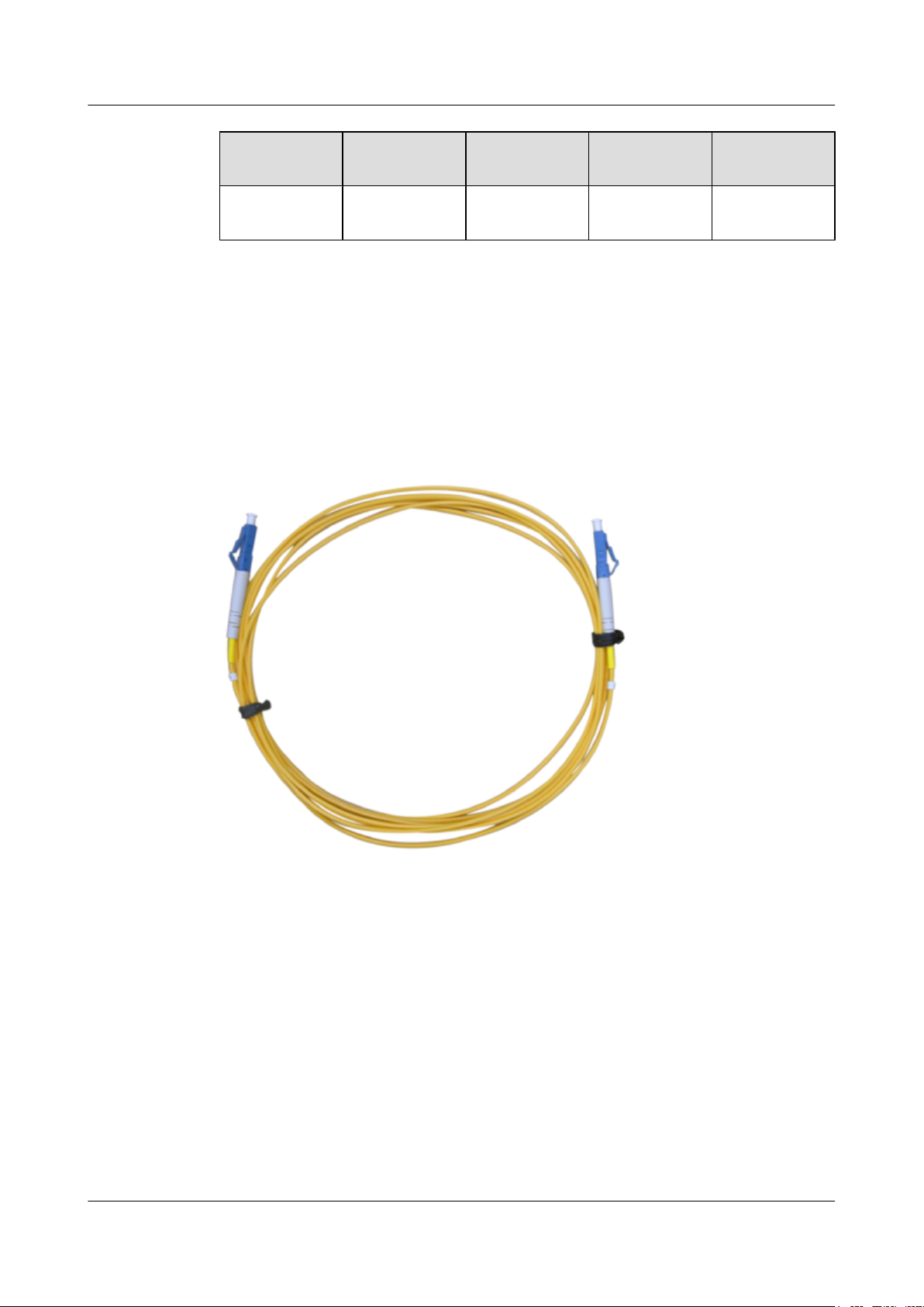
S6700 Series Ethernet Switches
Hardware Description 6 Cables
Fiber Jumper
Model Length Bend Radius Connector
Type
SFP-10GAOC10M
A fiber jumper consists of a length of a single fiber or multiple fibers with optical connectors at
both ends. The fiber jumper is a fiber patch cable that connects an optical module to a fiber
terminal box.
Figure 6-4 shows the appearance of a single-mode LC/PC fiber jumper.
Figure 6-4 Appearance of a single-mode LC/PC fiber jumper
10 m 30 mm
Operating
Temperature
Figure 6-5 shows the appearance of a multimode LC/PC fiber jumper.
Issue 12 (2015-07-31) Huawei Proprietary and Confidential
Copyright © Huawei Technologies Co., Ltd.
67
Page 77
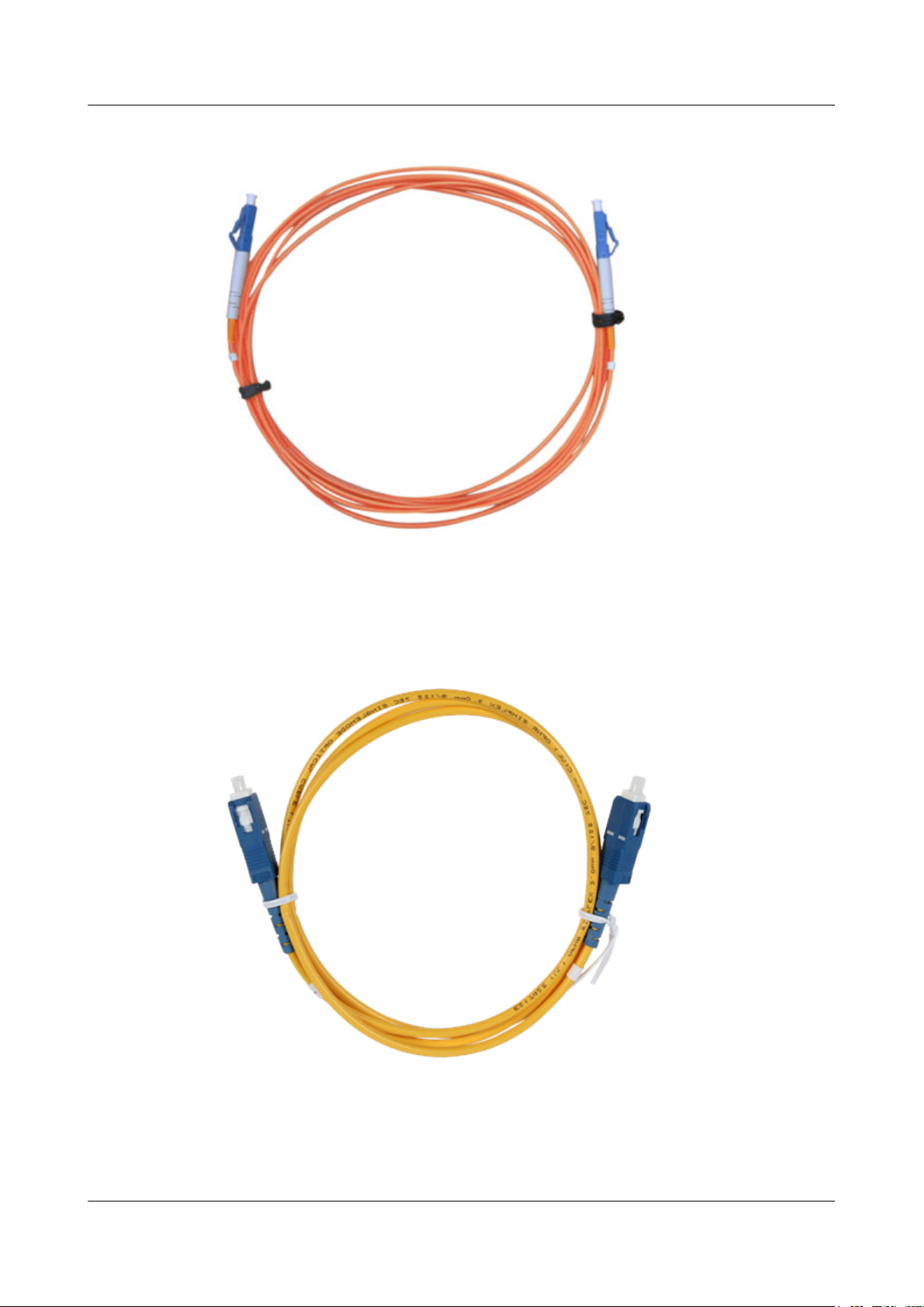
S6700 Series Ethernet Switches
Hardware Description
Figure 6-5 Appearance of a multimode LC/PC fiber jumper
6 Cables
Figure 6-6 shows the appearance of a single-mode SC/PC fiber jumper.
Figure 6-6 Appearance of a single-mode SC/PC fiber jumper
Figure 6-7 shows the appearance of an MPO-MPO fiber jumper.
Issue 12 (2015-07-31) Huawei Proprietary and Confidential
Copyright © Huawei Technologies Co., Ltd.
68
Page 78
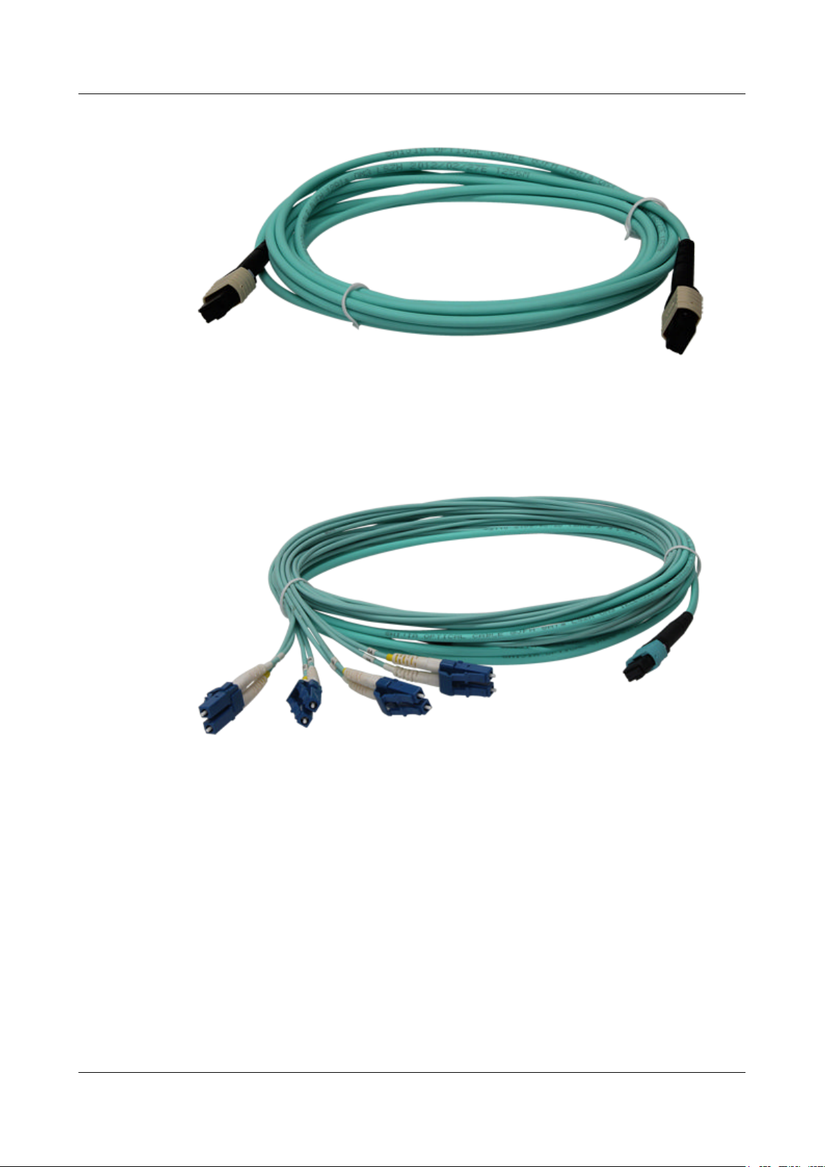
S6700 Series Ethernet Switches
Hardware Description
Figure 6-7 Appearance of an MPO-MPO fiber jumper
Figure 6-8 shows an MPO-4*DLC fiber jumper.
6 Cables
Figure 6-8 MPO-4*DLC fiber jumper
Select fiber jumpers according to the following rules:
1. Determine the length of fiber jumpers based on the actual cabling distance.
2. Determine the fiber type based on the optical module type.
l Use a multimode fiber jumper for a multimode optical module.
l Use a single-mode fiber jumper for a single-mode optical module.
3. Determine the optical connector type based on the interface type.
Ensure that the optical connector at each end of a fiber jumper is the same type as the
interface to which it will be connected.
Figure 6-9 shows the structure of an MPO-MPO fiber jumper.
Issue 12 (2015-07-31) Huawei Proprietary and Confidential
Copyright © Huawei Technologies Co., Ltd.
69
Page 79
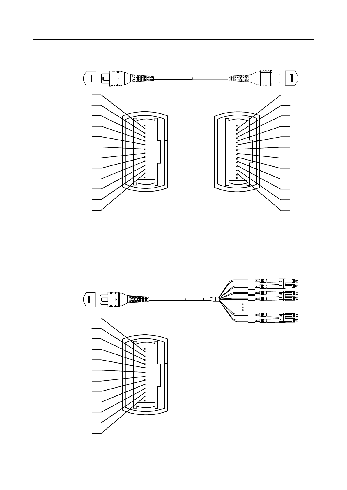
X1X2
1
2
3
4
5
6
7
8
9
10
11
12
12
11
10
9
8
7
6
5
4
3
2
1
X1
X2
1
2
3
4
5
6
7
8
9
10
11
12
1A
1B
2A
2B
4A
4B
S6700 Series Ethernet Switches
Hardware Description 6 Cables
Figure 6-9 Structure of an MPO-MPO fiber jumper
Figure 6-10 shows the structure of an MPO-4*DLC fiber jumper.
Figure 6-10 Structure of an MPO-4*DLC fiber jumper
Issue 12 (2015-07-31) Huawei Proprietary and Confidential
Copyright © Huawei Technologies Co., Ltd.
70
Page 80
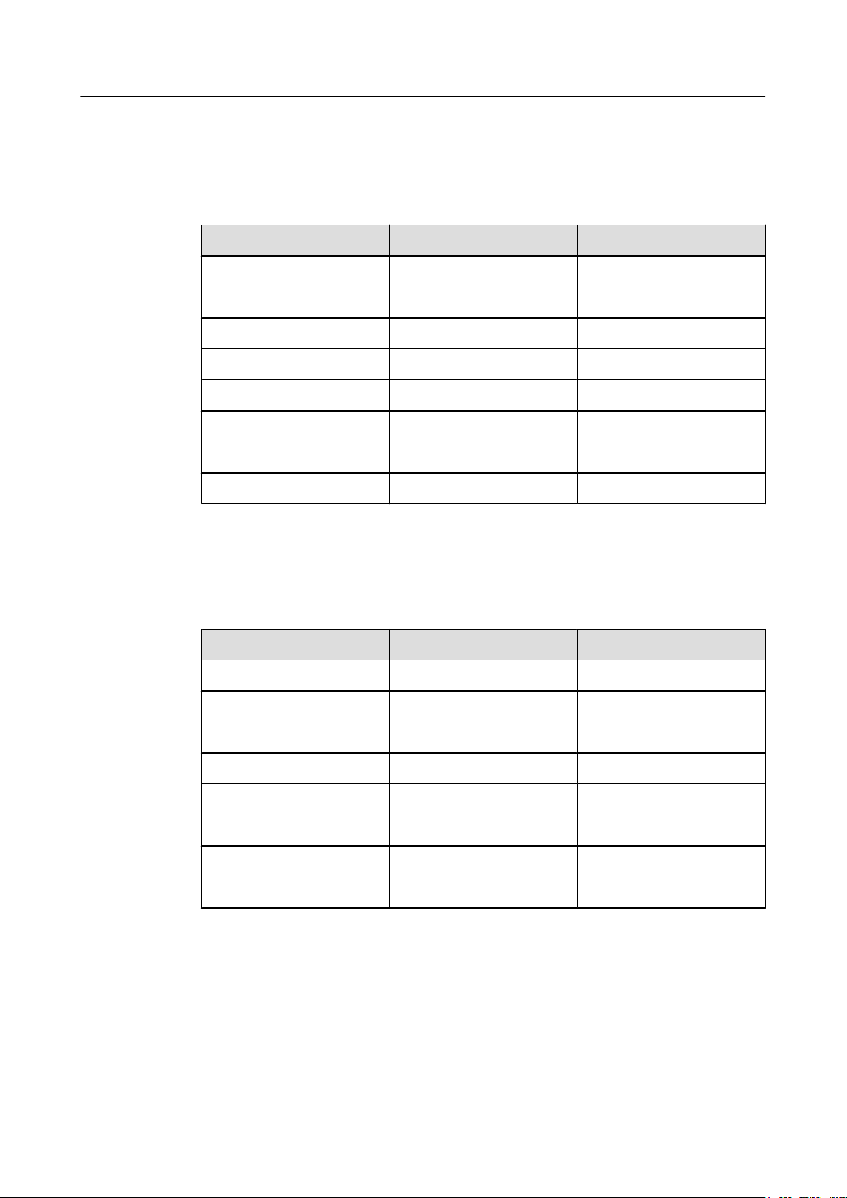
S6700 Series Ethernet Switches
Hardware Description
Table 6-3 describes the pin assignments of an MPO-MPO fiber jumper.
Table 6-3 Pin assignments of an MPO-MPO fiber jumper
Connector Type Wire Color X1 Pin
1 Blue 1
2 Orange 2
3 Green 3
4 Brown 4
9 Gray 9
10 White 10
11 Red 11
6 Cables
12 Black 12
Table 6-4 lists the pin assignments of an MPO-4*DLC fiber jumper.
Table 6-4 Pin assignments of an MPO-4*DLC fiber jumper
X2 Pin Wire Color X1 Pin
1 Blue 1A
2 Orange 2A
3 Green 3A
4 Brown 4A
9 Gray 4B
10 White 3B
11 Red 2B
12 Black 1B
Fiber Pigtail
A fiber pigtail is an optical fiber that has an optical connector on one end and a length of exposed
fiber at the other end. The exposed fiber can be fused to another optical fiber. Fiber pigtails are
commonly used to connect optical fibers to optical fiber modules in fiber terminal boxes.
(Couplers and jumpers are also used.) Figure 6-11 shows the structure of a fiber pigtail.
Issue 12 (2015-07-31) Huawei Proprietary and Confidential
Copyright © Huawei Technologies Co., Ltd.
71
Page 81
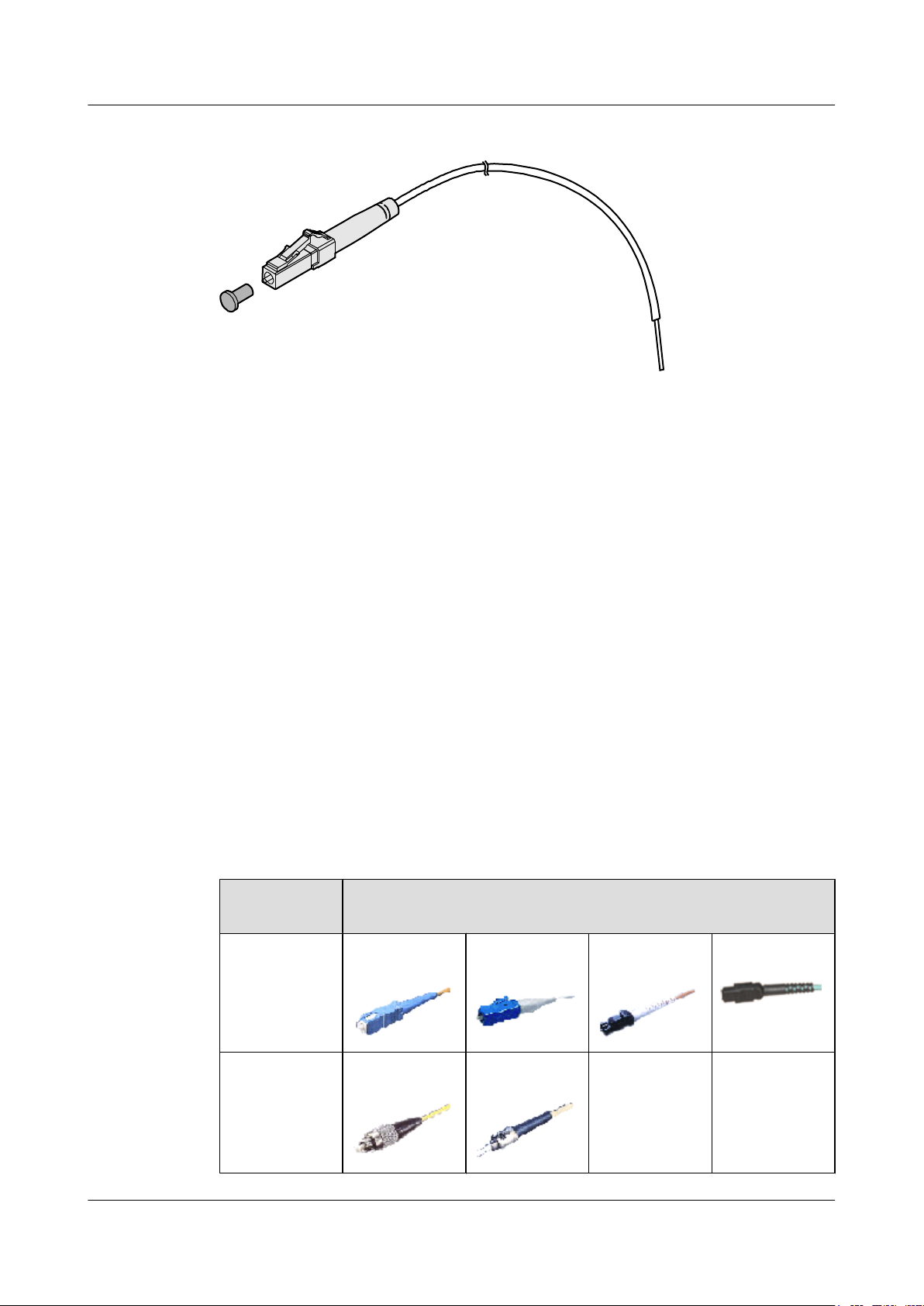
S6700 Series Ethernet Switches
Hardware Description 6 Cables
Figure 6-11 Structure of a fiber pigtail
Fiber pigtails are classified into single-mode and multimode fiber pigtails and are used for shortdistance connections.
Optical Fiber, Optical Connector, and Fiber Adapter
Optical Fibers
Optical fibers are classified into single-mode fibers and multimode fibers.
l Single-mode fibers have a diameter of 5-10 μm and transmit laser light in one mode with
a specified wavelength. These fibers support a wide frequency band and a high transmission
capacity, so they are used for long-distance transmission. Most single-mode fibers are
yellow, as shown in Figure 6-4.
l Multimode fibers have a diameter of 50 μm or 62.5 μm and transmit laser light in multiple
modes with a specified wavelength. These fibers have a lower transmission capacity than
single-mode fibers and are used for short-distance transmission. Model dispersion occurs
during transmission over multimode fibers. Most multimode fibers are orange, as shown
in Figure 6-5.
Optical Connector
Optical connectors are used to connect optical fibers of the same type. Table 6-5 lists common
optical connectors.
Table 6-5 Common optical connectors
Connector
Type
Square
connector
Optical Connector
SC/PC
connector
LC/PC
connector
MTRJ/PC
connector
MPO connector
Round
connector
Issue 12 (2015-07-31) Huawei Proprietary and Confidential
FC/PC
connector
Copyright © Huawei Technologies Co., Ltd.
ST/PC
connector
- -
72
Page 82

S6700 Series Ethernet Switches
Hardware Description
NOTICE
When connecting or removing a square connector, align the connector with the optical interface
and do not rotate the fiber. Pay attention to the following points:
l To connect a fiber, align the head of the fiber jumper with the optical interface and insert the
optical fiber into the interface gently.
l To remove a fiber, press the latch on the connector and pull the fiber out.
Fiber Adapter
A fiber adapter (also called a flange) is a fiber connection component. Fiber adapters are widely
used in optical distribution frames (ODF), fiber transmission equipment, or optical instruments.
6.3 Network Cable
6 Cables
Types of Network Cables
A network cable connects a maintenance terminal to the console port on the main control board
for local or remote maintenance.
Network cables are classified into straight-through cables and crossover cables.
l Straight-through cable: The twisted pairs in the RJ45 connectors at both ends are crimped
in the same sequence. A straight-through cable connects two devices of different types, for
example, a PC and a switch.
l Crossover cable: The twisted pairs in the RJ45 connectors at two ends are crimped in
different sequences. A crossover cable connects two devices or interfaces of the same type,
for example, two PCs.
Huawei switches support both straight-through and crossover cables and their ports are adaptive
to the cable types.
Appearance and Structure
NOTE
l Generally, a network cable is a standard unshielded network cable that uses RJ45 connectors.
l The appearances of the straight-through cable and the crossover cable are the same.
Figure 6-12 shows the appearance of a network cable.
Issue 12 (2015-07-31) Huawei Proprietary and Confidential
Copyright © Huawei Technologies Co., Ltd.
73
Page 83
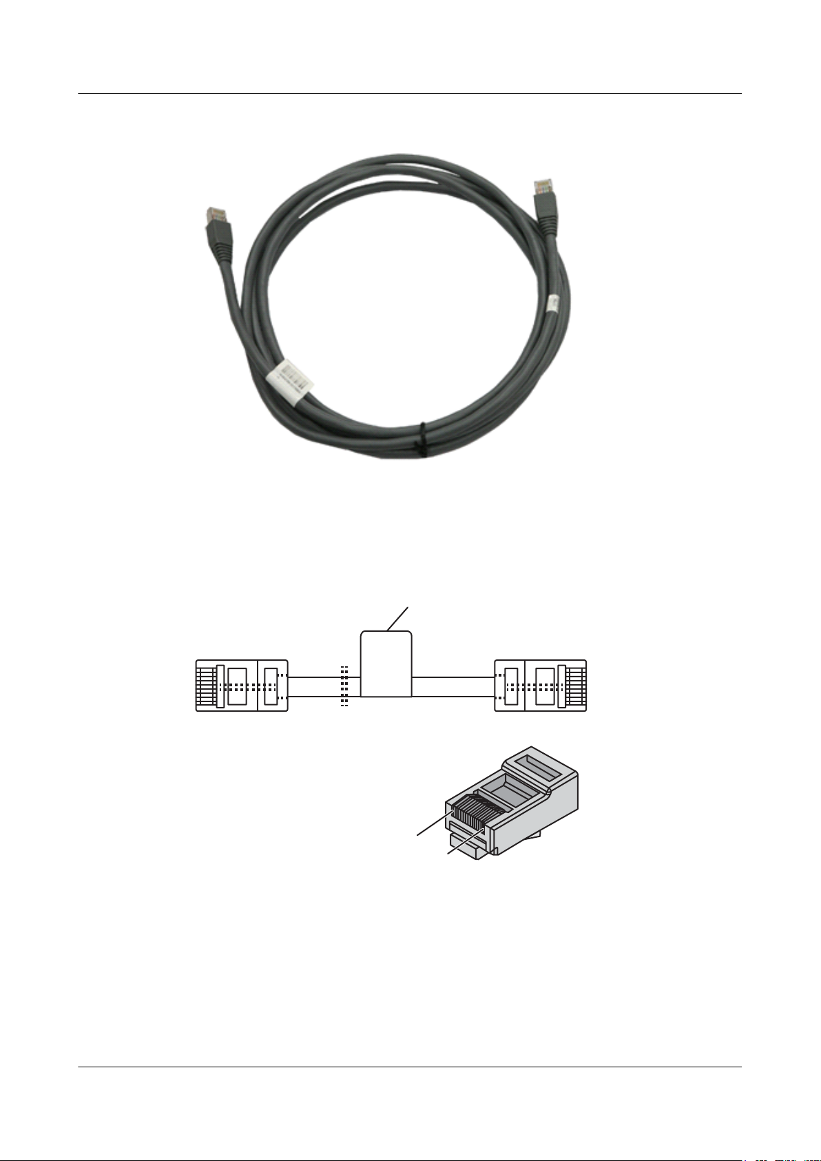
X1
8
1
Main label
X2
S6700 Series Ethernet Switches
Hardware Description
Figure 6-12 Appearance of a network cable
6 Cables
Figure 6-13 shows the structure of a network cable.
Figure 6-13 Structure of a network cable
Pin Assignments
Table 6-6 shows the pin assignments of a straight-through cable.
Issue 12 (2015-07-31) Huawei Proprietary and Confidential
Copyright © Huawei Technologies Co., Ltd.
74
Page 84
S6700 Series Ethernet Switches
Hardware Description
Table 6-6 Pin assignments of a straight-through cable
X1 Pin Wire Color X2 Pin
1 White and orange 1
2 Orange 2
3 White and green 3
4 Blue 4
5 White and blue 5
6 Green 6
7 White and brown 7
8 Brown 8
6 Cables
Table 6-7 shows the pin assignments of a crossover cable.
Table 6-7 Pin assignments of a crossover cable
X1 Pin Wire Color X2 Pin
1 White and orange 3
2 Orange 6
3 White and green 1
4 Blue 4
5 White and blue 5
6 Green 2
7 White and brown 7
8 Brown 8
NOTE
To achieve the best electrical transmission performance, ensure that the wires connected to pins 1 and 2 and to
pins 3 and 6 are twisted pairs.
6.4 DC Power Cable (OT and Cord End Terminals)
Issue 12 (2015-07-31) Huawei Proprietary and Confidential
Copyright © Huawei Technologies Co., Ltd.
75
Page 85
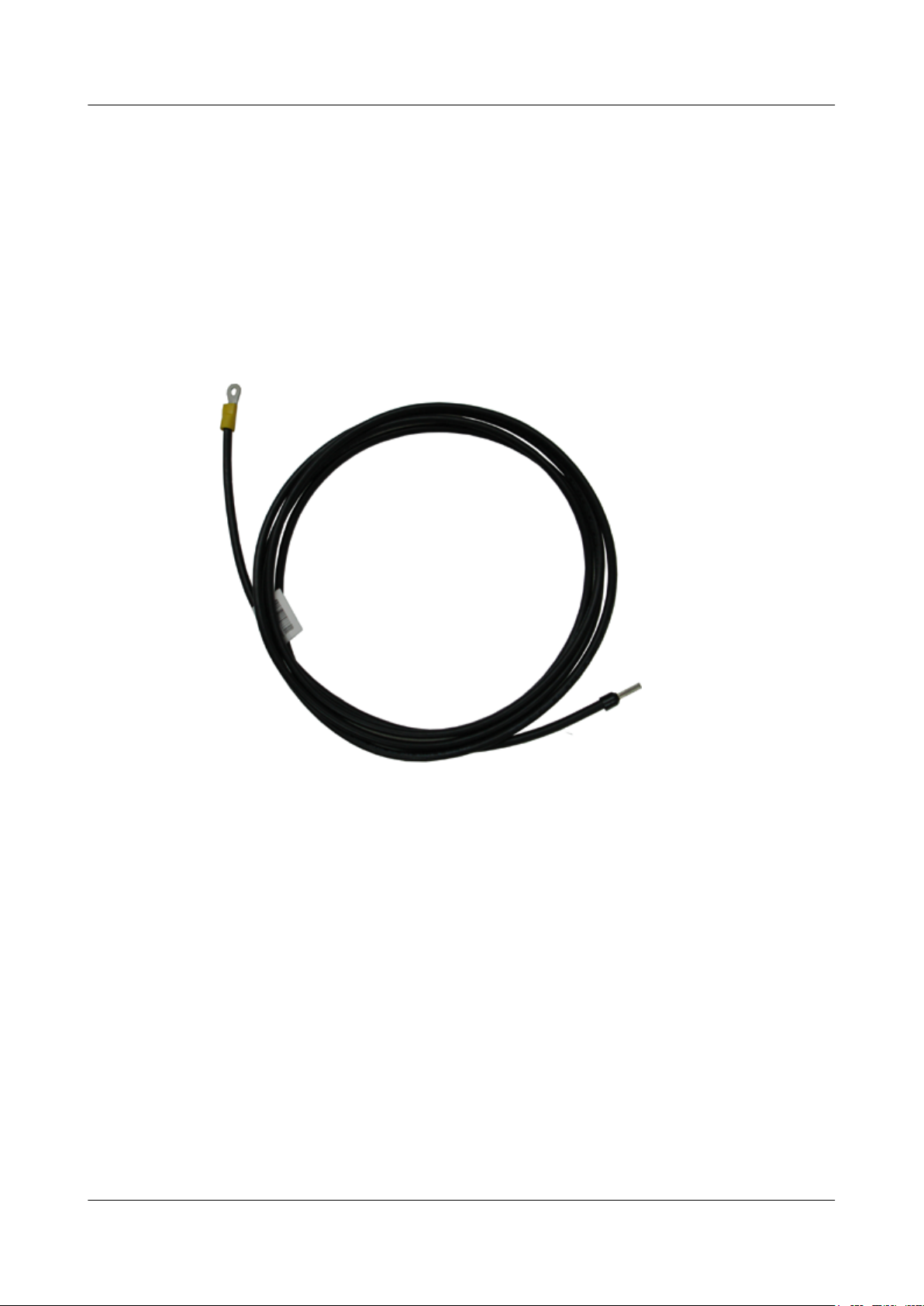
S6700 Series Ethernet Switches
Hardware Description 6 Cables
Types of DC Power Cables
DC power cables include a -48 V power return cable and a -48 V power cable. The -48 V power
return cable is connected to a terminal marked RTN (+), and the -48 V power cable is connected
to a terminal marked NEG (–).
Appearance and Structure
Figure 6-14 and Figure 6-15 show the appearance and structure of the 48 V power return cable
and -48 V power cable.
Figure 6-14 Appearance of a -48 V power return cable
Issue 12 (2015-07-31) Huawei Proprietary and Confidential
Copyright © Huawei Technologies Co., Ltd.
76
Page 86
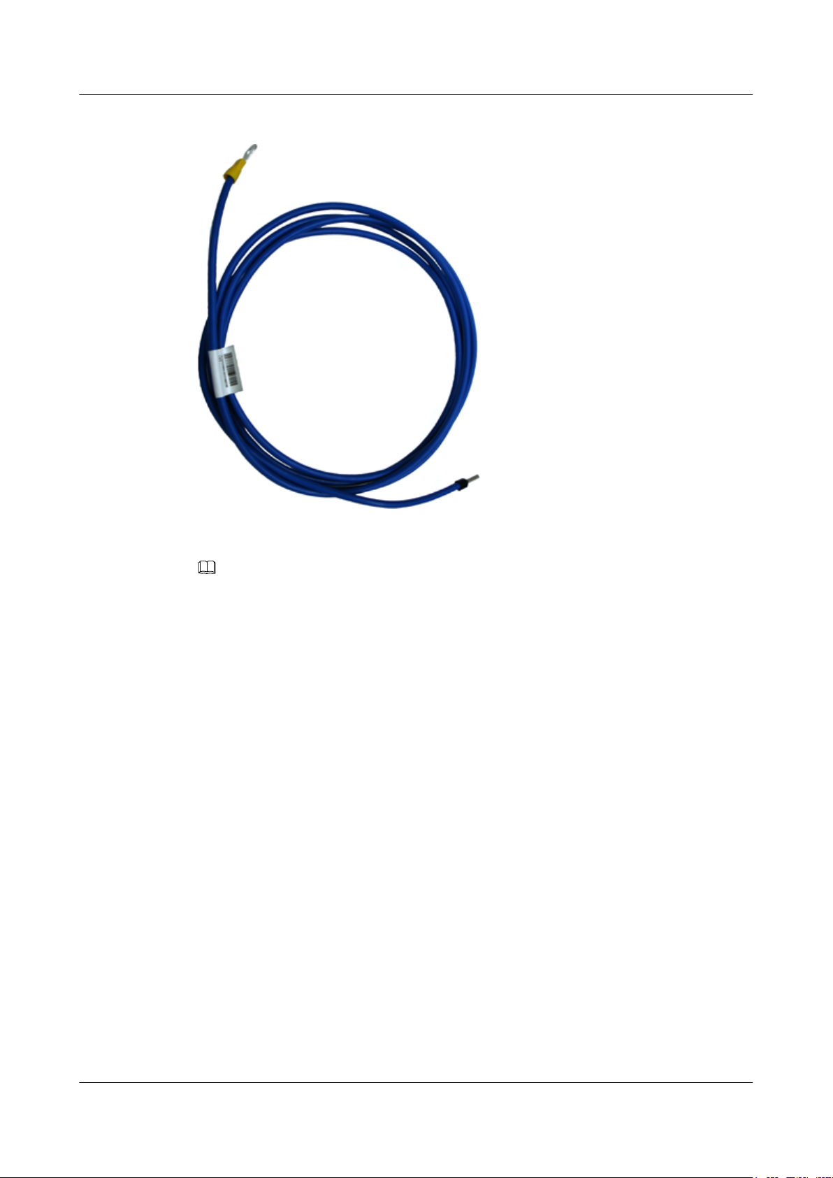
S6700 Series Ethernet Switches
Hardware Description
Figure 6-15 Appearance of a -48 V power cable
6 Cables
NOTE
A -48 V power return cable is black and is connected to the RTN(+) terminal of the DC power supply. A
-48 V power cable is blue and is connected to the NEG(-) terminal of the DC power supply.
Connection
A DC power cable is connected to a DC power module with OT terminals as follows:
l The OT terminal is connected to the input port on the DC power module of the device.
l The cord end terminal is connected to an external power module.
6.5 DC Power Cable (Quick-Connect Cord End Terminal)
Appearance and Structure
Figure 6-16 shows the appearance of a DC power cable.
Issue 12 (2015-07-31) Huawei Proprietary and Confidential
Copyright © Huawei Technologies Co., Ltd.
77
Page 87
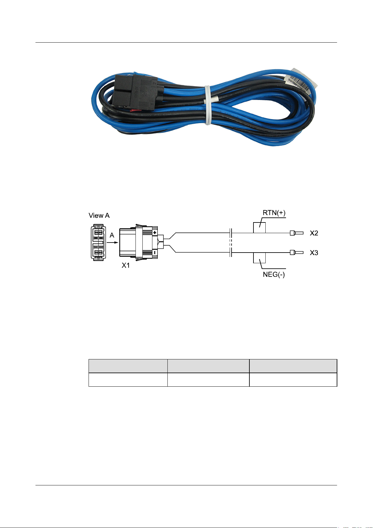
S6700 Series Ethernet Switches
Hardware Description
Figure 6-16 Appearance of a DC power cable
Figure 6-17 shows the structure of a DC power cable.
Figure 6-17 Structure of a DC power cable
6 Cables
Pin Assignments
Table 6-8 lists the pin assignments of a DC power cable.
Table 6-8 Pin assignments of a DC power cable
X1 X2 X3
2 female Cord end terminal 4^2 grey Cord end terminal 4^2 grey
Connection
A DC power cable (with quick-connect and cord end terminals) is connected a DC power module
with a quick-connect socket as follows:
l The X1 connector is connected to the power socket on the DC power module.
l The X2/X3 cord end terminal is connected to an external power module.
Issue 12 (2015-07-31) Huawei Proprietary and Confidential
Copyright © Huawei Technologies Co., Ltd.
78
Page 88
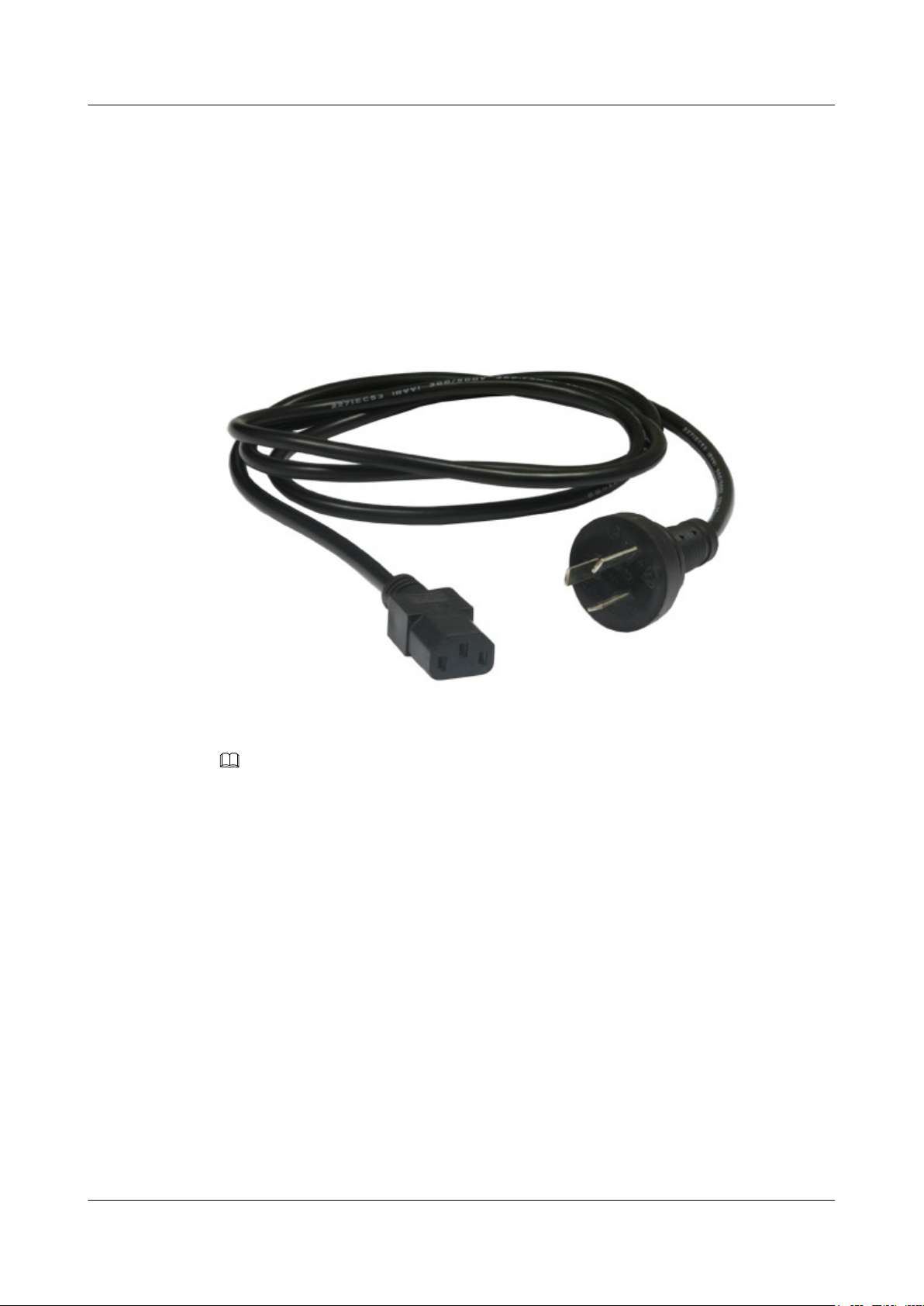
S6700 Series Ethernet Switches
Hardware Description
6.6 AC Power Cable
Appearance and Structure
Figure 6-18 shows the appearance of an AC power cable.
Figure 6-18 AC power cable
6 Cables
NOTE
The AC power cables used in different countries and regions may have different specifications. Figure
6-18 shows the AC power cable complying with China's national standard. The power cable and plug
delivered with the chassis can only be used on this chassis, and cannot be used on other devices.
Connection
An AC power cable connects to the following:
l An AC power input port on the device
l The mains supply
6.7 Console Cable
Appearance and Structure
Figure 6-19 and Figure 6-20 show the appearance and structure of a console cable.
Issue 12 (2015-07-31) Huawei Proprietary and Confidential
Copyright © Huawei Technologies Co., Ltd.
79
Page 89
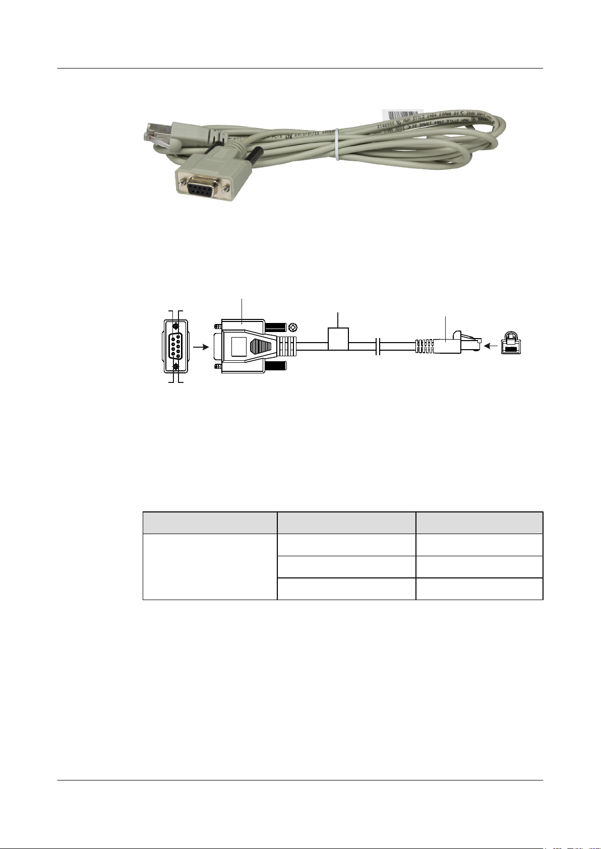
X1
Pos.1
Pos.9
Pos.6
Pos.5
X2
1 8
Serial port connector
(8-pin, RJ-45)
D-type connector
(9-pin, female)
Label
S6700 Series Ethernet Switches
Hardware Description
Figure 6-19 Appearance of a console cable
Figure 6-20 Structure of a console cable
6 Cables
Pin Assignments
Table 6-9 lists the pin assignments of console cable connectors.
Table 6-9 Pin assignments of console cable connectors
Connector X1 (DB9) X2 (RJ45)
Pin assignment 2 3
Connection
A console cable connects the console port of the device to the serial port of an operation terminal
to transmit configuration data. A shielded cable or an unshielded cable can be used according
to the onsite situation.
3 6
5 5
A console cable connects the device and terminal as follows:
Issue 12 (2015-07-31) Huawei Proprietary and Confidential
l The 8-pin RJ45 connector is inserted into the console port of the device.
l The DB9 connector is inserted into the terminal serial port.
Copyright © Huawei Technologies Co., Ltd.
80
Page 90
S6700 Series Ethernet Switches
Hardware Description
6.8 Copper Cable
Types of Copper Cables
Table 6-10 shows the types of copper cables.
Table 6-10 Types of copper cables
6 Cables
Model Length Electrical
attribute
SFP-10GCU1M
SFP-10GCU3M
SFP-10GCU5M
SFP-10GAC10M
QSFP-40GCU1M
QSFP-40GCU3M
QSFP-40GCU5M
QSFP-4SFP10
G-CU1M
1 m Passive 25 mm SFP+
3 m Passive 25 mm SFP+
5 m Passive 30 mm SFP+
10 m Active 25 mm SFP+
1 m Passive 55 mm QSFP+
3 m Passive 60.5 mm QSFP+
5 m Passive 67 mm QSFP+
1 m Passive 25 mm QSFP+ to
Bend Radius Connector
Type
4*SFP+
QSFP-4SFP10
G-CU3M
QSFP-4SFP10
G-CU5M
3 m Passive 25 mm QSFP+ to
5 m Passive 50 mm QSFP+ to
NOTICE
The two ends of a copper cable must be covered by electrostatic discharge (ESD) caps.
When used for data transmission between service ports, copper cables can only connect switches
of the same subseries, and cannot be used between switches of different subseries or between
Huawei and non-Huawei switches.
Issue 12 (2015-07-31) Huawei Proprietary and Confidential
Copyright © Huawei Technologies Co., Ltd.
4*SFP+
4*SFP+
81
Page 91
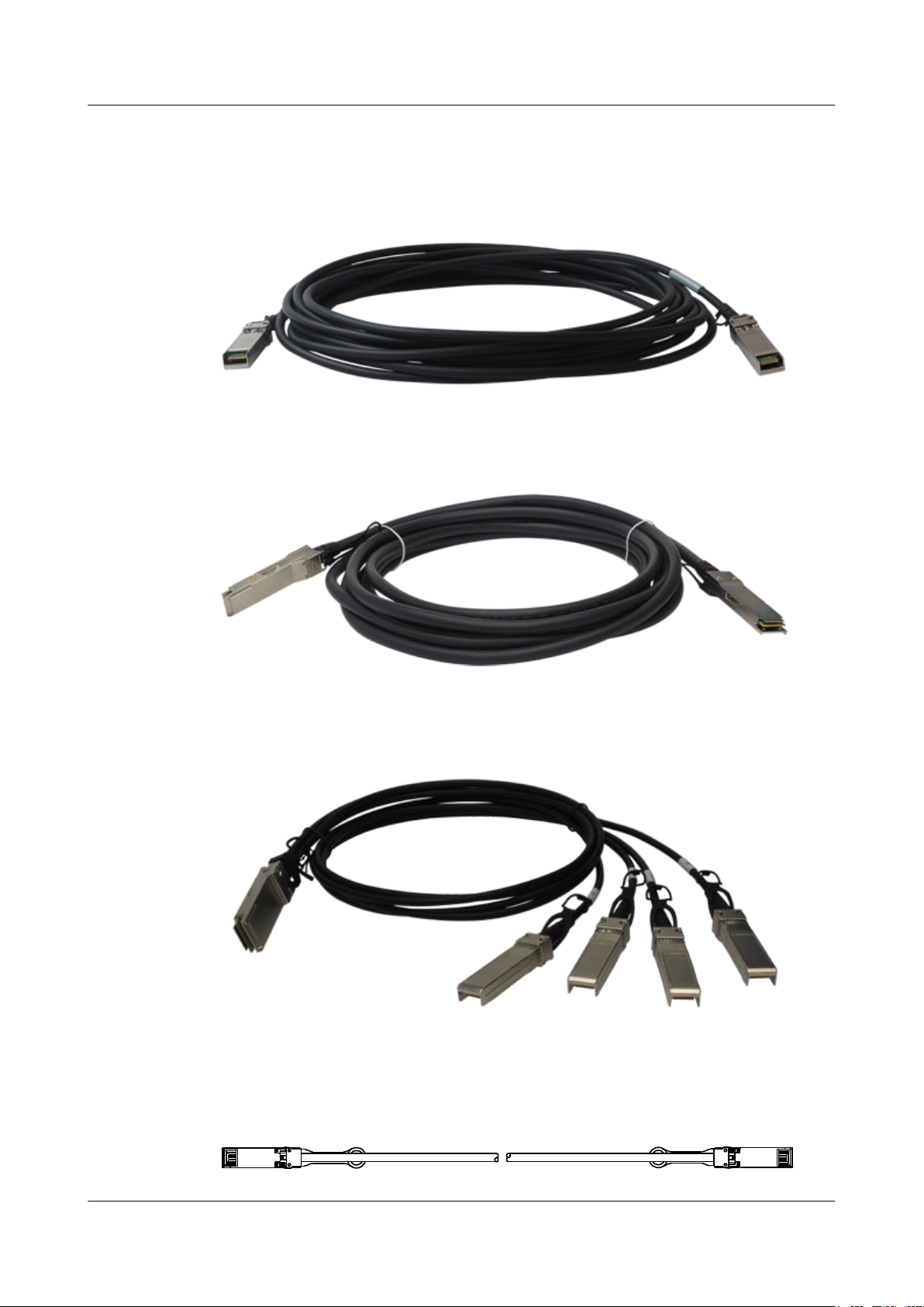
X1X2
S6700 Series Ethernet Switches
Hardware Description
Appearance and Structure
Figure 6-21 shows the appearance of an SFP/SFP+ copper cable.
Figure 6-21 Appearance of an SFP/SFP+ copper cable
Figure 6-22 shows the appearance of a QSFP+ copper cable.
Figure 6-22 Appearance of a QSFP+ copper cable
6 Cables
Figure 6-23 shows the appearance of a QSFP+ to 4*SFP+ copper cable.
Figure 6-23 Appearance of a QSFP+ to 4*SFP+ copper cable
Figure 6-24 shows the structure of an SFP/SFP+ copper cable.
Figure 6-24 Structure of an SFP/SFP+ copper cable
Issue 12 (2015-07-31) Huawei Proprietary and Confidential
Copyright © Huawei Technologies Co., Ltd.
82
Page 92
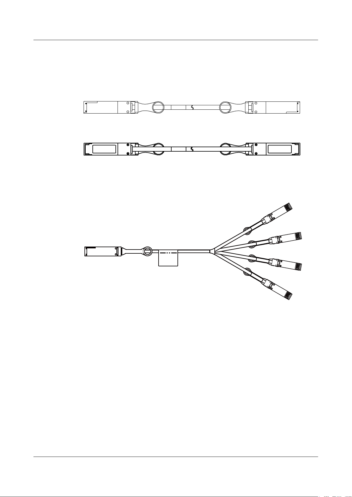
X1 X2
X1X2
X1
X2
A
B
D
C
S6700 Series Ethernet Switches
Hardware Description
Figure 6-25 shows the structure of a QSFP+ copper cable.
Figure 6-25 Structure of a QSFP+ copper cable
Front view:
Rear view:
Figure 6-26 shows the structure of a QSFP+ to 4*SFP+ copper cable.
Figure 6-26 Structure of a QSFP+ to 4*SFP+ copper cable
6 Cables
Stack Description
In addition to data transmission, copper cables can be used for stack connection.
Before setting up a stack, familiarize yourself with the device-supported stack connection modes
and software and hardware requirements. For details, see "Determining the Stack Connection
Mode and Software and Hardware Requirements" under "Typical Stack Configuration" in the
Typical Configuration Examples.
Issue 12 (2015-07-31) Huawei Proprietary and Confidential
Copyright © Huawei Technologies Co., Ltd.
83
Page 93

S6700 Series Ethernet Switches
Hardware Description 7 Pluggable Modules for Interfaces
7 Pluggable Modules for Interfaces
About This Chapter
7.1 Important Notes About Using Optical Modules Certified for Huawei Switches
7.2 Understanding Optical Modules
7.3 Understanding Copper Modules
7.4 Models and Parameters
Issue 12 (2015-07-31) Huawei Proprietary and Confidential
Copyright © Huawei Technologies Co., Ltd.
84
Page 94
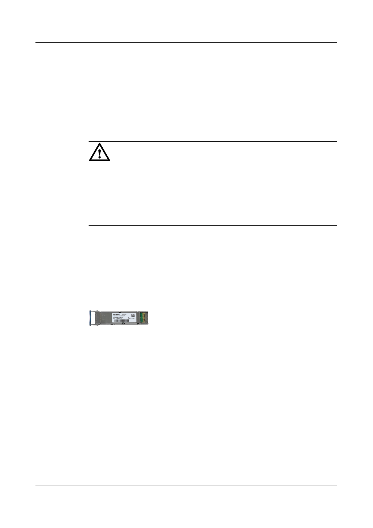
S6700 Series Ethernet Switches
Hardware Description
7 Pluggable Modules for Interfaces
7.1 Important Notes About Using Optical Modules Certified for Huawei Switches
7.1.1 How to Identify Huawei-Certified Optical Modules
NOTICE
l Huawei switches must use Huawei-certified optical modules. Non-Huawei-certified optical
modules cannot ensure transmission reliability and may affect service stability. Huawei is
not liable for any problem caused by the use of non-Huawei-certified optical modules and
will not fix such problems.
l The methods provided here are only for reference. To confirm whether optical modules you
use have been certified by Huawei, contact Huawei Technical Assistant Center (TAC).
If the optical modules you use are delivered after July 1, 2013, use either of the following methods
to determine whether they have been certified by Huawei.
Method 1: Check for "HUAWEI" on the Label
If an optical module has been certified by Huawei, its label contains "HAUWEI", as shown in
Figure 7-1.
Figure 7-1 "HUAWEI" on the label of a Huawei-certified optical module
Method 2: Run the display transceiver Command
If an optical module meets the following conditions, it has been certified by Huawei. Otherwise,
the optical module is not a Huawei-certified one.
l In the display elabel command output, the Manufactured field displays a date later than
2013-07-01.
l In the display version command output, the display version is V200R001C00 or later.
l In the display transceiver command output, the Manufacturing Date field displays a date
later than 2013-07-01, and the Vendor Name field displays HUAWEI.
7.1.2 Risks of Using Non-Huawei-Certified Optical Modules
During certification of optical modules for Huawei switches, Huawei completes comprehensive
functionality verification to ensure quality of optical modules. The verified items include optical
module plug/unplug, transmit optical power, receive optical power, signal transmission quality,
Issue 12 (2015-07-31) Huawei Proprietary and Confidential
Copyright © Huawei Technologies Co., Ltd.
85
Page 95

S6700 Series Ethernet Switches
Hardware Description
data reading, error tolerance, compatibility, electromagnetic compatibility (EMC), and
environmental parameters.
Non-Huawei-certified optical modules may cause the following problems:
l Non-standard structure and size cause failures to install optical modules on adjacent optical
interfaces.
Structures or sizes of some non-Huawei-certified optical modules do not comply with the
Multi-Source Agreement (MSA). When such an optical module is installed on an optical
interface, the size of this optical module hinders optical module installation on adjacent
optical interfaces.
l Data bus defects cause suspension of a switch's data bus.
Some non-Huawei-certified optical modules have defects in data bus designs. Using such
an optical module on a switch causes suspension of the connected data bus on the switch.
As a result, data on the suspended bus cannot be read.
l Improper edge connector size damages electronic devices of optical interfaces.
If a non-Huawei-certified optical module with improper edge connector size is used on an
optical interface, electronic devices of the optical interface will be damaged by short
circuits.
7 Pluggable Modules for Interfaces
l Unnormalized temperature monitoring causes incorrect alarms.
The temperature monitoring systems of some non-Huawei-certified optical modules do not
comply with industry standards and report temperature values higher than the real
temperature. When such optical modules are used on a switch, the system will report
incorrect temperature alarms.
l Improper register settings cause errors or failures in reading parameters or diagnostic
information.
Some non-Huawei-certified optical modules have improper register values on page A0,
which can cause errors or failures when the system attempts to read parameters or diagnostic
information from a data bus.
l Some non-Huawei-certified optical modules are not designed in compliance with EMC
standards and have low anti-interference capability. Additionally, they bring
electromagnetic interference to nearby devices.
l The operating temperature ranges of non-Huawei-certified optical modules cannot meet
service requirements. When they are used under relatively high temperature, the optical
power decreases, resulting in service interruption.
7.2 Understanding Optical Modules
7.2.1 What Is an Optical Module
On an optical network, a sender needs to convert electrical signals into optical signals before
sending them to a receiver, and the receiver needs to convert received optical signals into
electrical signals. An optical module is a component that completes electrical/optical conversion
on an optical network. Figure 7-2 shows the structure of an optical module.
Issue 12 (2015-07-31) Huawei Proprietary and Confidential
Copyright © Huawei Technologies Co., Ltd.
86
Page 96
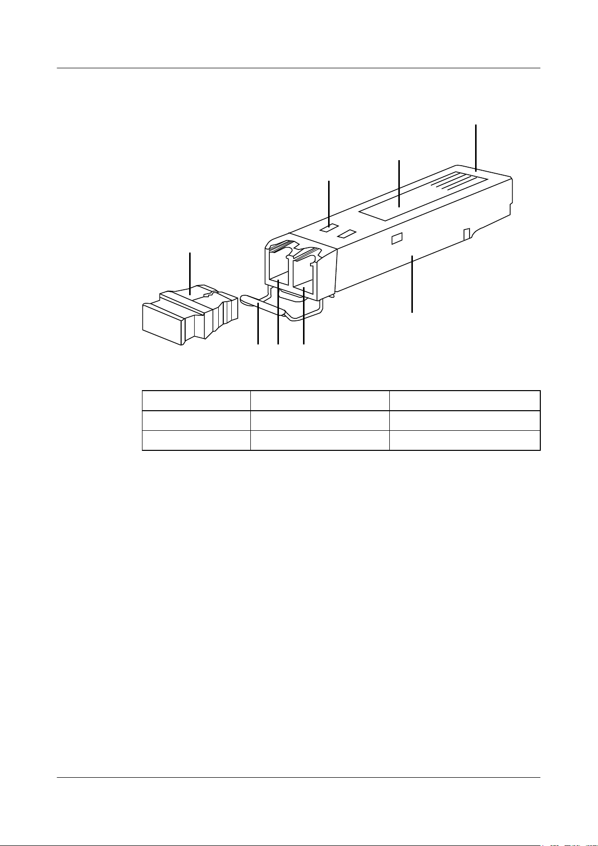
1 3 2
4
5
8
7
6
S6700 Series Ethernet Switches
Hardware Description
Figure 7-2 Structure of an optical module
7 Pluggable Modules for Interfaces
1. Handle 2. Receiver 3. Transmitter
4. Shell 5. Label 6. Dust plug
7. Spring 8. Connector -
7.2.2 Types of Optical Modules
Optical modules are available in various types to meet diversified requirements.
l Classified by transmission rates
Depending on transmission rates, optical modules are classified into 40GE, 10GE and GE
optical modules.
l Classified by encapsulation types
The higher transmission rate an optical module provides, the more complex structure it has.
Optical modules are encapsulated in different modes to provide different structures. Huawei
switches support optical modules of the following encapsulation types: QSFP+, SFP, eSFP,
and SFP+.
– SFP: small form-factor pluggable. SFP optical modules support LC fiber connectors
and are hot swappable.
– eSFP: enhanced small form-factor pluggable. An eSFP module is an SFP module that
supports monitoring of voltage, temperature, bias current, transmit optical power, and
Issue 12 (2015-07-31) Huawei Proprietary and Confidential
receive optical power. Therefore, eSFP is also called SFP sometimes.
– SFP+: small form-factor pluggable plus, SFP with a higher rate. SFP+ optical modules
are more sensitive to electromagnetic interference (EMI) because they have a higher
Copyright © Huawei Technologies Co., Ltd.
87
Page 97
S6700 Series Ethernet Switches
Hardware Description 7 Pluggable Modules for Interfaces
rate. To reduce EMI, SFP+ optical modules have more springs than SFP optical modules
and the cages for SFP+ modules on a card are tighter.
– QSFP+: quad small form-factor pluggable. QSFP+ optical modules support MPO fiber
connectors and are larger than SFP+ optical modules.
l Classified by physical layer standards
Different physical layer standards are defined to allow data transmission in different modes.
Therefore, different types of optical modules are produced to comply with these standards.
The Standard column of Table 7-1 lists the physical layer standards.
l Classified by modes
Optical fibers are classified into single-mode and multimode fibers. Therefore, optical
modules are also classified into single-mode and multimode modules to support different
optical fibers.
– Single-mode optical modules are used with single-mode fibers. Single-mode fibers
support a wide band and large transmission capacity, and are used for long-distance
transmission.
– Multimode optical modules are used with multimode fibers. Multimode fibers have
lower transmission performance than single-mode fibers because of modal dispersion,
but their costs are also lower. They are used for small-capacity, short-distance
transmission.
Table 7-1 provides optical module classification based on different factors.
Table 7-1 Optical module classification
Encapsul
Rate Standard Description
ation
Type
eSFP GE 1000BASE-SX (IEEE
802.3z)
Uses one single-mode fiber for
bidirectional transmission at 1 Gbit/s
over a distance within 1 km.
1000base-LX/LH (IEEE
802.3ah)
Uses one Rx single-mode fiber and
one Tx single-mode fiber to transmit
data at 1 Gbit/s over a distance within
40 km.
1000base-ZX (IEEE
802.3)
Uses one Rx single-mode fiber and
one Tx single-mode fiber to transmit
data at 1 Gbit/s over a distance within
100 km.
1000base-BX (IEEE
802.3ah)
Uses one single-mode fiber for
bidirectional transmission at 1 Gbit/s
over a distance within 80 km.
CWDM (IEEE 802.3) Coarse wavelength division
Issue 12 (2015-07-31) Huawei Proprietary and Confidential
Copyright © Huawei Technologies Co., Ltd.
multiplexing, which uses one singlemode fiber to transmit signals on
multiple channels. It transmits data at
1 Gbit/s over a distance within 80 km.
88
Page 98

S6700 Series Ethernet Switches
Hardware Description 7 Pluggable Modules for Interfaces
Encapsul
Rate Standard Description
ation
Type
DWDM (IEEE 802.3) Dense wavelength division
SFP+ 10GE 10Gbase-USR (IEEE
802.3)
10Gbase-BX (IEEE
802.3)
10GBASE-iLR Uses one Rx multimode fiber and one
multiplexing, which uses one singlemode fiber to transmit signals on
multiple channels. It transmits data at
1 Gbit/s over a distance within 120
km.
Uses one Rx multimode fiber and one
Tx multimode fiber to transmit data at
10 Gbit/s over a distance within 100
m.
Uses one single-mode fiber for
bidirectional transmission at 10 Gbit/
s over a distance within 10 km.
Tx multimode fiber to transmit data at
10 Gbit/s over a distance within 1.4
km.
SFP+ 10GE 10GBASE-SR (IEEE
802.3ae)
10GBASE-LR (IEEE
802.3ae)
10GBASE-ER (IEEE
802.3ae)
10Gbase-ZR (IEEE
802.3)
QSFP+ 40GE 40Gbase-SR4 (IEEE
802.3ba)
Uses one Rx multimode fiber and one
Tx multimode fiber to transmit data at
10 Gbit/s over a distance within 400
m.
Uses one Rx single-mode fiber and
one Tx single-mode fiber to transmit
data at 10 Gbit/s over a distance within
10 km.
Uses one Rx single-mode fiber and
one Tx single-mode fiber to transmit
data at 10 Gbit/s over a distance within
40 km.
Uses one Rx single-mode fiber and
one Tx single-mode fiber to transmit
data at 10 Gbit/s over a distance within
80 km.
Uses one Rx multimode fiber and one
Tx multimode fiber to transmit data at
40 Gbit/s over a distance within 150
m.
40Gbase-LR4 (IEEE
802.3ba)
Issue 12 (2015-07-31) Huawei Proprietary and Confidential
Copyright © Huawei Technologies Co., Ltd.
Uses one Rx single-mode fiber and
one Tx single-mode fiber to transmit
data at 40 Gbit/s over a distance within
10 km.
89
Page 99
S6700 Series Ethernet Switches
Hardware Description 7 Pluggable Modules for Interfaces
Encapsul
Rate Standard Description
ation
Type
7.2.3 Parameter Description
40GBASE-ER4 (IEEE
802.3ba)
40Gbase-iSR4 (IEEE
802.3ba)
40Gbase-eSR4 (IEEE
802.3ba)
Uses one Rx single-mode fiber and
one Tx single-mode fiber to transmit
data at 40 Gbit/s over a distance within
40 km.
Uses one Rx multimode fiber and one
Tx multimode fiber to transmit data at
40 Gbit/s over a distance within 150
m.
Uses one Rx multimode fiber and one
Tx multimode fiber to transmit data at
40 Gbit/s over a distance within 400
m.
Transmit optical power
Output optical power of an optical module when it is working properly. When two optical
modules are connected, the transmit optical power of one end must be within the range
of receive optical power on the other end.
Receive optical power Average input optical power that the receiver of an optical module can receive within a
range of bit error rate (BER = 10
-12
). The upper limit of this parameter is the overload
optical power and the lower limit is the maximum receiver sensitivity. When two optical
modules are connected, the receive optical power on one end determines the range of
transmit optical power on the other end.
Maximum receiver
sensitivity
Minimum average input optical power that the receiver of an optical module can receive
within a range of bit error rate (BER = 10
-12
). When two optical modules are connected,
the maximum receiver sensitivity on one end determines the minimum value of transmit
optical power on the other end.
Overload optical power Maximum average input optical power that the receiver of an optical module can receive
within a range of bit error rate (BER = 10
-12
). When two optical modules are connected,
the overload optical power on one end determines the maximum transmit optical power
on the other end.
Extinction ratio Minimum ratio of the average optical power with signals transmitted against the average
optical power without signals transmitted in complete modulation mode. The extinction
ratio indicates the capability of an optical module to identify signal 0 and signal 1. This
parameter is a quality indicator for optical modules. Optical modules with a large
extinction ratio may not have good quality. Qualified optical modules should have an
extinction ratio complying with IEEE 802.3.
Issue 12 (2015-07-31) Huawei Proprietary and Confidential
Copyright © Huawei Technologies Co., Ltd.
90
Page 100

S6700 Series Ethernet Switches
Hardware Description
Fiber mode Mode of optical fibers defined based on core diameters and features of optical fibers.
Optical fibers are classified into single-mode and multimode fibers. Generally,
multimode fibers have large core diameters and severe dispersion, so they are used to
transmit optical signals over short distances. Single-mode fibers have smaller diameters
and small dispersion, so they can transmit optical signals over long distances.
Modal bandwidth Bandwidth measured at a point with transmit power several dB lower than that of the
point with the peak center wavelength. Modal bandwidth reflects spectrum
characteristics of multimode fibers. The higher modal bandwidth a multimode fiber has,
the longer transmission distance the fiber supports.
Fiber diameter Diameter of the core of a fiber. According to international standards for optical fibers,
the diameter of a multimode fiber is 62.5 um or 50 um, and the diameter of a singlemode fiber is 9 um. Select optical fibers with diameters supported by the optical modules.
Fiber class Optical signals with different wavelengths have their best working windows in different
optical fibers. To help efficiently adjust wavelengths or dispersion features of optical
fibers and change their refractive indexes, the following fiber classes are defined:
multimode fiber (G.651), common single-mode fiber (G.652), shifted dispersion fiber
(G.653), and non-zero shifted dispersion fiber (G.655). G.651 and G.652 are commonly
used fiber classes. Optical fibers of higher classes support longer transmission distances.
When selecting optical fibers for optical modules, determine the classes of fibers based
on the required transmission distances.
7 Pluggable Modules for Interfaces
Connector type Type of the interface on an optical module to accommodate a fiber. Commonly used
connector types are LC (applicable to all the SFP, SFP+, and XFP modules), SC, and
MPO (applicable to 150 m QSFP+ and CXP modules). Select optical fibers with
connectors supported the optical modules.
Transmission distance Maximum distance over which optical signals can transmit. Optical signals sent from
different types of sources can transmit over different distances due to negative effects of
optical fibers, such as dispersion and attenuation. When connecting optical interfaces,
select optical modules and fibers based on the maximum signal transmission distance.
Interface rate Maximum rate of electrical signals that an optical component can transmit without bit
errors. The interface rates defined in Ethernet standards include 125 Mbit/s, 1.25 Gbit/
s, 10.3125 Gbit/s, and 41.25 Gbit/s. When connecting optical interfaces, select optical
modules and fibers based on the maximum signal transmission rate.
Center wavelength Wavelength measured at the midpoint of the half-amplitude line in the transmit spectrum.
Two connected optical modules must have the same center wavelength.
MSA Multi-Source Agreement, a non-profit organization jointly established by optical module
manufacturers. This agreement defines the structure and dimensions of optical
transceivers by referring to Optical Internetworking Forum (OIF) and International
Telecommunication Union (ITU) standards.
7.2.4 How to View Optical Module Parameters
Issue 12 (2015-07-31) Huawei Proprietary and Confidential
Copyright © Huawei Technologies Co., Ltd.
91
 Loading...