

Huawei RH2288 V3 User Manual

RH2288 V3 Server
V100R003
User Guide
Issue 32
Date 2019-03-28
HUAWEI TECHNOLOGIES CO., LTD.

Copyright © Huawei Technologies Co., Ltd. 2019. All rights reserved.
No part of this document may be reproduced or transmitted in any form or by any means without prior written
consent of Huawei Technologies Co., Ltd.
Trademarks and Permissions
and other Huawei trademarks are trademarks of Huawei Technologies Co., Ltd.
All other trademarks and trade names mentioned in this document are the property of their respective
holders.
Notice
The purchased products, services and features are stipulated by the contract made between Huawei and the
customer. All or part of the products, services and features described in this document may not be within the
purchase scope or the usage scope. Unless otherwise specified in the contract, all statements, information,
and recommendations in this document are provided "AS IS" without warranties, guarantees or
representations of any kind, either express or implied.
The information in this document is subject to change without notice. Every effort has been made in the
preparation of this document to ensure accuracy of the contents, but all statements, information, and
recommendations in this document do not constitute a warranty of any kind, express or implied.
Huawei Technologies Co., Ltd.
Address: Huawei Industrial Base
Bantian, Longgang
Shenzhen 518129
People's Republic of China
Website: http://e.huawei.com
Issue 32 (2019-03-28) Copyright © Huawei Technologies Co., Ltd. i
RH2288 V3 Server
User Guide
Purpose
About This Document
About This Document
This document describes the appearance, features, and specifications of the RH2288 V3 and
explains how to install and remove the server and its parts, power on and off, configure, and
troubleshoot the server.
Read this document before operating the RH2288 V3.
Intended Audience
This document is intended for:
l Technical support engineers
l Maintenance engineers
Symbol Conventions
The symbols that may be found in this document are defined as follows.
Symbol
Description
Indicates an imminently hazardous situation which, if
not avoided, will result in death or serious injury.
Indicates a potentially hazardous situation which, if not
avoided, could result in death or serious injury.
Indicates a potentially hazardous situation which, if not
avoided, may result in minor or moderate injury.
Indicates a potentially hazardous situation which, if not
avoided, could result in equipment damage, data loss,
performance deterioration, or unanticipated results.
NOTICE is used to address practices not related to
personal injury.
Issue 32 (2019-03-28) Copyright © Huawei Technologies Co., Ltd. ii
RH2288 V3 Server
User Guide
Symbol Description
Change History
Changes between document issues are cumulative. The latest document issue contains all
changes made in previous issues.
About This Document
Calls attention to important information, best practices
and tips.
NOTE is used to address information not related to
personal injury, equipment damage, and environment
deterioration.
Issue
32 2019-03-28 Deleted the LCD description.
31 2018-11-19 Optimized the flexible NIC indicator description. For
30 2018-10-19 Added the list of components where the sensors are
29 2018-09-17 Added the description about the information that will
28 2018-08-17 Added the procedure for removing a holding rail. For
27 2018-07-12 Added procedures for removing and installing an SD
26 2018-05-29 Changed LOM and NIC to flexible NIC.
Date Description
details, see 2.4 Indicators and Buttons.
located. For details, see 11.3 Sensor List.
be lost after mainboard replacement and needs to be
configured again after the mainboard is replaced.
Added the link for importing and exporting the BMC
configuration file to sections 7.42 Installing the
Mainboard and 7.41 Removing the Mainboard.
details, see 3.6 Removing the Server.
card and related precautions. For details, see 7.49
Removing an SD Card Board and 7.50 Installing an
SD Card Board.
25 2018-05-10 Modified fan module removal and installation
procedures. For details, see 7.15 Removing a Fan
Module and 7.16 Installing a Fan Module.
Issue 32 (2019-03-28) Copyright © Huawei Technologies Co., Ltd. iii
RH2288 V3 Server
User Guide
About This Document
Issue Date Description
24 2018-04-10 Modified RAID controller card supercapacitor
removal and installation procedures. For details, see
7.33 Removing the Supercapacitor (Screw-in RAID
Controller Card), 7.34 Removing the
Supercapacitor (PCIe Plug-in RAID Controller
Card), 7.35 Installing the Supercapacitor (Screw-in
RAID Controller Card), and 7.36 Installing the
Supercapacitor (PCIe Plug-in RAID Controller
Card).
23 2018-02-22 Added the description about how to import and export
the iBMC/BIOS configuration information after the
mainboard is replaced. For details, see 7.41
Removing the Mainboard and 7.42 Installing the
Mainboard.
22 2018-01-15 Added the locations of dual SD cards. For details, see
7.47 Removing an SD Card.
Added the description about the left and right
mounting ears. For details, see 2.2 Appearance.
Added 750 W Titanium PSU indicator states and their
meanings. For details, see 2.4 Indicators and
Buttons.
21 2017-12-12 Modified server installation environment
requirements. For details, see 3.2 Installation
Environment.
Added fan module numbers. For details, see 7.15
Removing a Fan Module.
20 2017-10-26 Added the description about SD cards and dual-SD
module. For details, see 2.5 Physical Structure.
19 2017-09-26 Changed optional chip types. For details, see 2.7
Internal Cabling.
18 2017-08-15 Optimized chapters about parts replacement. For
details, see 7 Replacing Parts.
17 2017-07-20 Added the description about 128 GB DIMMs. For
details, see 2.5 Physical Structure and 2.11 Product
Specifications.
16 2017-06-20 Added internal cable BOMs. For details, see 2.7
Internal Cabling.
15 2017-05-10 Modified the mainboard layout description. For
details, see 2.6 Mainboard Layout.
14 2017-04-05 Modified front bezel description. For details, see 7.3
(Optional) Removing the Front Bezel and 7.4
(Optional) Installing the Front Bezel.
Issue 32 (2019-03-28) Copyright © Huawei Technologies Co., Ltd. iv
RH2288 V3 Server
User Guide
About This Document
Issue Date Description
13 2017-03-03 Modified the configuration description. For details,
see 2.1 Introduction.
12 2017-01-24 Added description about replacing the front bezel
during hard disk replacement. For details, see 7.5
Removing a Hard Disk and 7.6 Installing a Hard
Disk.
11 2016-11-29 Added information about CPU installation tool. For
details, see 7.37 Removing a CPU and 7.38
Installing a CPU.
Modified the indicator status description of the NVMe
PCIe SSD installation. For details, see 7.8 Installing
an NVMe PCIe SSD.
10 2016-10-10 Modified the disk installation direction for servers that
support 8 x 2.5-inch, 24 x 2.5-inch, or 25 x 2.5-inch
hard disks. For details, see 2.2 Appearance.
09 2016-07-30 Added security description. For details, see 1 Safety
Instructions.
Added the description of the Software and
Configuration Utility. For details, see 6 Software and
Configuration Utility.
08 2016-03-30 Added the procedures for removing and installing an
NVMe PCIe SSD. For details, see 7.7 Removing an
NVMe PCIe SSD and 7.8 Installing an NVMe PCIe
SSD.
Added the procedures for removing and installing an
M.2 SATA SSD card. For details, see 7.61 Removing
an M.2 SATA SSD Card and 7.62 Installing an M.2
SATA SSD Card.
07 2015-11-06 Modified the mainboard layout description. For
details, see 2.6 Mainboard Layout.
06 2015-10-15 Added the procedure for operating the front bezel. For
details, see 7.3 (Optional) Removing the Front
Bezel and 7.4 (Optional) Installing the Front Bezel.
Added internal cabling. For details, see 2.7 Internal
Cabling.
05 2015-06-10 Added the procedure for removing the RH2288 V3
installed on the holding rails. For details, see 7.11
Removing the Chassis Cover.
04 2015-03-27 Added product specifications. For details, see 2.11
Product Specifications.
03 2014-12-30 Modified the product name.
Issue 32 (2019-03-28) Copyright © Huawei Technologies Co., Ltd. v

RH2288 V3 Server
User Guide
About This Document
Issue Date Description
02 2014-12-10 Added the guide rail requirements on the chassis. For
details, see 2.12 Physical Specifications.
01 2014-08-30 This issue is the first official release.
Issue 32 (2019-03-28) Copyright © Huawei Technologies Co., Ltd. vi

RH2288 V3 Server
User Guide Contents
Contents
About This Document.....................................................................................................................ii
1 Safety Instructions.........................................................................................................................1
2 Overview......................................................................................................................................... 5
2.1 Introduction.................................................................................................................................................................... 5
2.2 Appearance..................................................................................................................................................................... 8
2.3 Ports.............................................................................................................................................................................. 17
2.4 Indicators and Buttons.................................................................................................................................................. 18
2.5 Physical Structure......................................................................................................................................................... 25
2.6 Mainboard Layout........................................................................................................................................................ 32
2.7 Internal Cabling............................................................................................................................................................ 34
2.7.1 Internal Cabling for an M.2 SSD Riser Card.............................................................................................................34
2.7.2 Internal Cabling for 8-Disk Configuration 1............................................................................................................. 37
2.7.3 Internal Cabling for 8-Disk Configuration 2............................................................................................................. 38
2.7.4 Internal Cabling for 12-Disk Configuration.............................................................................................................. 40
2.7.5 Internal Cabling for 24-Disk Configuration.............................................................................................................. 45
2.7.6 Internal Cabling for 25-Disk Configuration.............................................................................................................. 50
2.8 Logical Structure.......................................................................................................................................................... 51
2.9 RAS Features................................................................................................................................................................52
2.10 Software and Hardware Compatibility....................................................................................................................... 54
2.11 Technical Specifications............................................................................................................................................. 55
2.12 Physical and Environmental Specifications............................................................................................................... 60
3 Installing and Removing the Server........................................................................................ 63
3.1 Installation Overview................................................................................................................................................... 63
3.2 Installation Environment.............................................................................................................................................. 64
3.2.1 Space and Airflow Requirements.............................................................................................................................. 64
3.2.2 Temperature and Humidity Requirements................................................................................................................. 65
3.2.3 Cabinet Requirements................................................................................................................................................65
3.3 Unpacking the Chassis..................................................................................................................................................66
3.4 Installing the Server......................................................................................................................................................66
3.4.1 Installing the Server on L-Shaped Guide Rails......................................................................................................... 67
3.4.2 Installing the Server on Adjustable Guide Rails....................................................................................................... 69
3.4.3 Installing the Server on Holding Rails...................................................................................................................... 71
Issue 32 (2019-03-28) Copyright © Huawei Technologies Co., Ltd. vii

RH2288 V3 Server
User Guide Contents
3.5 Connecting External Cables......................................................................................................................................... 77
3.5.1 Connecting Cables to a Mouse, Keyboard, and VGA Port....................................................................................... 77
3.5.2 Connecting a Network Cable.....................................................................................................................................78
3.5.3 Connecting a Cable to a 10GE Port...........................................................................................................................80
3.5.4 Connecting a 56G IB Cable.......................................................................................................................................83
3.5.5 Connecting a USB Device.........................................................................................................................................85
3.5.6 Connecting a Serial Cable......................................................................................................................................... 85
3.5.7 Connecting a Power Cable........................................................................................................................................ 86
3.5.8 Laying Out Cables..................................................................................................................................................... 89
3.5.9 Verifying Cable Connections.....................................................................................................................................90
3.6 Removing the Server.................................................................................................................................................... 90
3.6.1 Removing the Server and L-Shaped Guide Rails......................................................................................................90
3.6.2 Removing a Server and Adjustable Guide Rail.........................................................................................................92
3.6.3 Removing the Server and Holding Rails................................................................................................................... 93
4 Powering On and Off the Server..............................................................................................97
4.1 Powering On the Server................................................................................................................................................97
4.2 Powering Off the Server............................................................................................................................................... 99
5 Configuring the RH2288 V3.................................................................................................... 101
5.1 Default Information.................................................................................................................................................... 101
5.2 Configuration Process.................................................................................................................................................102
5.3 Checking the RH2288 V3...........................................................................................................................................103
5.4 Configuring RAID......................................................................................................................................................107
5.5 Configuring the BIOS.................................................................................................................................................108
5.6 Changing an iBMC User Password............................................................................................................................ 116
5.7 Setting the Management Network Port IP Address....................................................................................................117
5.8 Installing an OS.......................................................................................................................................................... 121
5.9 (Optional) Configuring the Boot from iSCSI Function for an SP230 flexible NIC...................................................121
6 Software and Configuration Utility.......................................................................................122
6.1 BIOS........................................................................................................................................................................... 122
6.2 iBMC.......................................................................................................................................................................... 123
6.3 Upgrading Software....................................................................................................................................................123
7 Replacing Parts...........................................................................................................................127
7.1 Replaceable Parts........................................................................................................................................................129
7.2 Tool Preparations........................................................................................................................................................ 130
7.3 (Optional) Removing the Front Bezel........................................................................................................................ 130
7.4 (Optional) Installing the Front Bezel..........................................................................................................................132
7.5 Removing a Hard Disk............................................................................................................................................... 135
7.6 Installing a Hard Disk.................................................................................................................................................137
7.7 Removing an NVMe PCIe SSD................................................................................................................................. 138
7.8 Installing an NVMe PCIe SSD...................................................................................................................................138
7.9 Removing a PSU........................................................................................................................................................ 138
Issue 32 (2019-03-28) Copyright © Huawei Technologies Co., Ltd. viii

RH2288 V3 Server
User Guide Contents
7.9.1 Removing an AC PSU.............................................................................................................................................138
7.9.2 Removing a DC PSU...............................................................................................................................................140
7.10 Installing a PSU........................................................................................................................................................ 142
7.10.1 Installing an AC PSU............................................................................................................................................ 142
7.10.2 Installing a DC PSU.............................................................................................................................................. 144
7.11 Removing the Chassis Cover....................................................................................................................................146
7.12 Installing the Chassis Cover..................................................................................................................................... 147
7.13 Removing the Air Duct.............................................................................................................................................149
7.14 Installing the Air Duct.............................................................................................................................................. 150
7.15 Removing a Fan Module.......................................................................................................................................... 152
7.16 Installing a Fan Module............................................................................................................................................154
7.17 Removing an Internal Cable..................................................................................................................................... 156
7.18 Installing an Internal Cable.......................................................................................................................................157
7.19 Removing the Riser Card......................................................................................................................................... 159
7.20 Installing a Riser Card.............................................................................................................................................. 160
7.21 Removing a PCIe Card............................................................................................................................................. 162
7.21.1 Removing a PCIe Card from a Riser Card............................................................................................................ 162
7.21.2 Removing a PCIe Card from the Mainboard.........................................................................................................164
7.22 Installing a PCIe Card...............................................................................................................................................165
7.22.1 Installing a PCIe Card on the Riser Card.............................................................................................................. 165
7.22.2 Installing a PCIe Card on the Mainboard.............................................................................................................. 166
7.23 Removing the DVD Drive........................................................................................................................................167
7.24 Installing the DVD Drive......................................................................................................................................... 172
7.25 Removing the Internal USB Flash Drive..................................................................................................................175
7.26 Installing the Internal USB Flash Drive................................................................................................................... 176
7.27 Removing the System Battery.................................................................................................................................. 177
7.28 Installing the System Battery....................................................................................................................................178
7.29 Removing the Screw-in RAID Controller Card....................................................................................................... 180
7.30 Installing the Screw-in RAID Controller Card.........................................................................................................181
7.31 Removing the PCIe Plug-in RAID Controller Card.................................................................................................183
7.32 Installing the PCIe Plug-in RAID Controller Card.................................................................................................. 183
7.33 Removing the Supercapacitor (Screw-in RAID Controller Card)............................................................................184
7.34 Removing the Supercapacitor (PCIe Plug-in RAID Controller Card)..................................................................... 187
7.35 Installing the Supercapacitor (Screw-in RAID Controller Card)............................................................................. 189
7.36 Installing the Supercapacitor (PCIe Plug-in RAID Controller Card).......................................................................191
7.37 Removing a CPU...................................................................................................................................................... 194
7.38 Installing a CPU........................................................................................................................................................198
7.39 Removing a DIMM.................................................................................................................................................. 204
7.40 Installing a DIMM.................................................................................................................................................... 205
7.41 Removing the Mainboard......................................................................................................................................... 208
7.42 Installing the Mainboard...........................................................................................................................................213
7.43 Removing the Flexible NIC......................................................................................................................................217
Issue 32 (2019-03-28) Copyright © Huawei Technologies Co., Ltd. ix

RH2288 V3 Server
User Guide Contents
7.44 Installing the Flexible NIC....................................................................................................................................... 218
7.45 Removing a SATADOM...........................................................................................................................................220
7.46 Installing a SATADOM............................................................................................................................................ 221
7.47 Removing an SD Card..............................................................................................................................................223
7.48 Installing an SD Card............................................................................................................................................... 227
7.49 Removing an SD Card Board................................................................................................................................... 231
7.50 Installing an SD Card Board.....................................................................................................................................232
7.51 Removing the Front Disk Backplane........................................................................................................................234
7.52 Installing the Front Disk Backplane......................................................................................................................... 235
7.53 Removing the Rear Disk Backplane.........................................................................................................................237
7.54 Installing the Rear Disk Backplane.......................................................................................................................... 238
7.55 Removing the VGA Board....................................................................................................................................... 241
7.56 Installing the VGA Board.........................................................................................................................................245
7.57 Removing the PSU Backplane................................................................................................................................. 250
7.58 Installing the PSU Backplane................................................................................................................................... 251
7.59 Removing the Left Mounting Ear.............................................................................................................................252
7.60 Installing the Left Mounting Ear.............................................................................................................................. 255
7.61 Removing the Right Mounting Ear.......................................................................................................................... 256
7.62 Installing the Right Mounting Ear............................................................................................................................ 259
7.63 Removing an M.2 SATA SSD Card......................................................................................................................... 261
7.64 Installing an M.2 SATA SSD Card...........................................................................................................................262
8 Troubleshooting........................................................................................................................ 265
9 Common Operations.................................................................................................................266
9.1 Querying the IP Address of the Management Network Port......................................................................................266
9.2 Logging In to the iBMC WebUI................................................................................................................................. 268
9.3 Logging In to the iBMC CLI......................................................................................................................................270
9.4 Logging In to the Server Using the Independent Remote Console............................................................................ 273
9.5 Logging In to the Server over a Serial Port Using PuTTY........................................................................................ 279
9.6 Logging In to the Server over a Network Port Using PuTTY....................................................................................281
9.7 Opening the Remote Virtual Console.........................................................................................................................283
9.8 Querying the Mapping Between NVMe PCIe SSD Drive Letters, Slot IDs, and Bus IDs in Linux......................... 285
9.9 Erasing Storage Media Data....................................................................................................................................... 287
10 Obtaining Help........................................................................................................................ 293
10.1 Collecting Fault Information.................................................................................................................................... 293
10.2 Preparing for Debugging.......................................................................................................................................... 293
10.3 Using Product Documentation..................................................................................................................................293
10.4 Obtaining Technical Support.................................................................................................................................... 294
11 Appendix...................................................................................................................................295
11.1 Glossary.................................................................................................................................................................... 295
11.2 Acronyms and Abbreviations................................................................................................................................... 296
Issue 32 (2019-03-28) Copyright © Huawei Technologies Co., Ltd. x

RH2288 V3 Server
User Guide Contents
11.3 Sensor List................................................................................................................................................................ 299
Issue 32 (2019-03-28) Copyright © Huawei Technologies Co., Ltd. xi
RH2288 V3 Server
User Guide
General Instructions
l Comply with all local laws and regulations when installing the hardware. These Safety
Instructions are only a supplement.
l Observe the instructions that accompany all "DANGER", "WARNING", "CAUTION",
and "NOTE" symbols in this document. Follow them in conjunction with these Safety
Instructions.
l Observe all safety instructions provided on the device labels when installing hardware.
Follow them in conjunction with these Safety Instructions.
l Only personnel (such as electricians and forklift operators) who are certified by the local
government or official organizations are allowed to perform hardware installation.
l The product is a Class A device. Take protective measures against radio interference
before operating the device in residential areas.
1 Safety Instructions
1 Safety Instructions
Personal Safety
l Ensure that only personnel authorized by Huawei install hardware.
l In case of any problems that may cause injury to personnel or damage to devices,
immediately stop operations and report the problems to a project supervisor and take
corrective measures.
l Do not move devices or install cabinets and power cables in hazardous weather
conditions.
l For lifting or carrying hardware, ensure load limits and manpower provisions conform to
legal specifications.
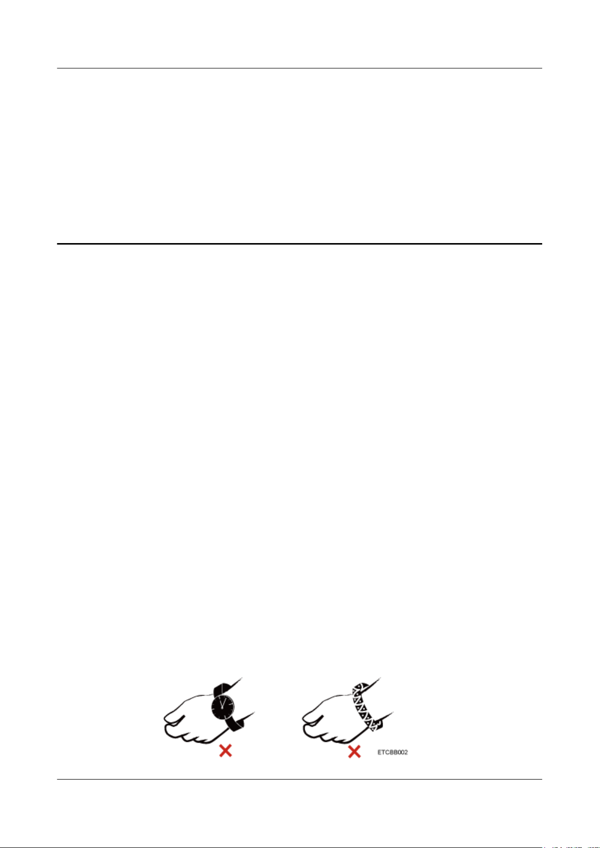
l Remove electricity-conductive materials such as watches and jewelry, as shown in
Figure 1-1.
Figure 1-1 Removing easily-conductive objects
Issue 32 (2019-03-28) Copyright © Huawei Technologies Co., Ltd. 1
RH2288 V3 Server
User Guide
1 Safety Instructions
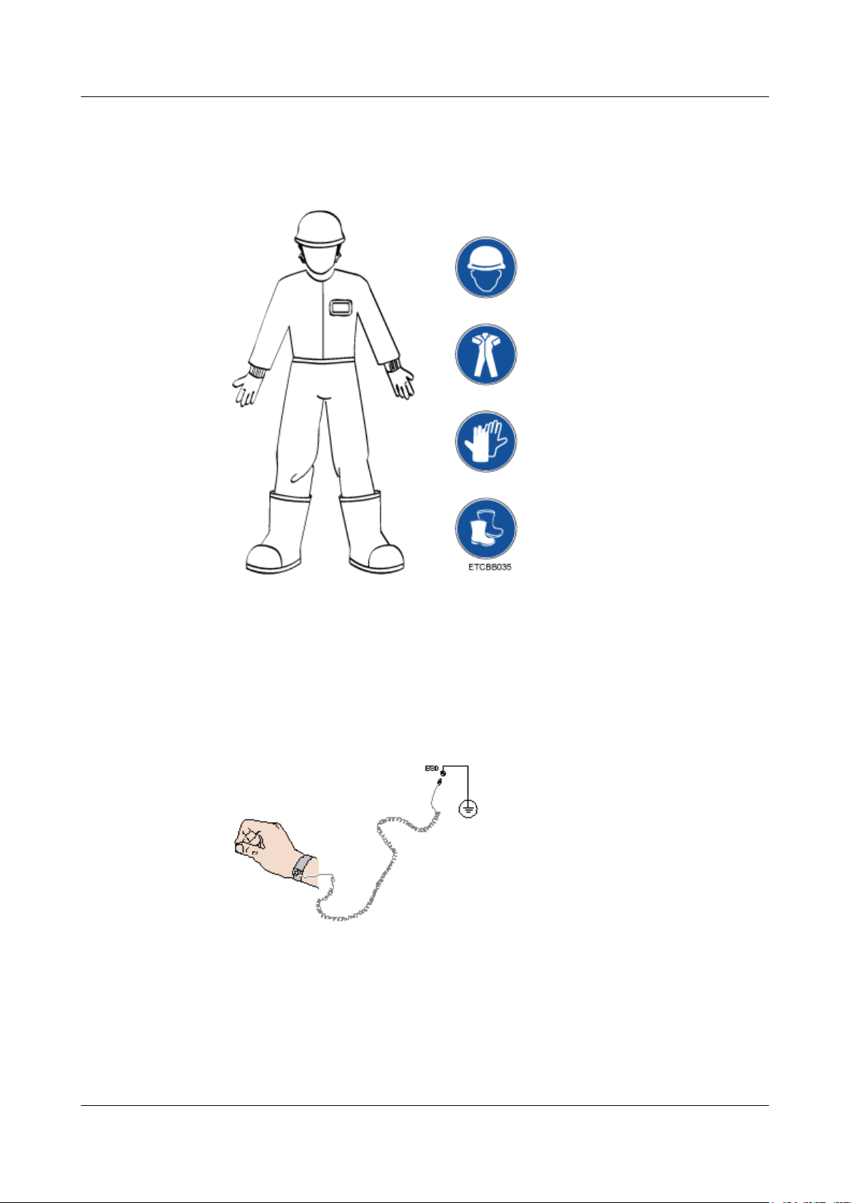
l Wear clean protective gloves, ESD clothing, a protective hat, and protective shoes, as
shown in Figure 1-2.
Figure 1-2 Protective clothing
Figure 1-3 shows how to wear an ESD wrist strap.
1. Put on the ESD wrist strap.
2. Fasten the buckle and ensure that the ESD wrist strap is in good contact with your skin.
3. Insert the ground terminal of the ESD wrist strap into the jack on the grounded cabinet or
chassis.
Figure 1-3 Wearing an ESD wrist strap
l Exercise caution when using tools to prevent injuries.
l If the position for installing the device is higher than your shoulders, use a stacker to lift
the device to prevent it from falling on top of you.
l High-voltage power supply provides power for device operation. Do not touch high-
voltage cables directly or through conductive materials. This may cause danger of
electrocution.
Issue 32 (2019-03-28) Copyright © Huawei Technologies Co., Ltd. 2

RH2288 V3 Server
User Guide
l Before powering on a device, ground it to prevent injuries.
l Do not use the ladder unsupervised. Have someone else hold the ladder steady to prevent
accidents.
l Do not view the open optical port directly when installing, testing, or replacing optical
cables to prevent laser radiation from injuring your eyes.
Transportation Precautions
Contact the manufacturer for precautions before attempting transportation.
l The logistics company engaged to transport the equipment must be reliable and comply
with international standards for transporting electronics. Ensure that the equipment being
transported is kept upright and avoid collision, damp conditions, corrosion, package
damage, and pollution.
l Transport the equipment in its original packaging.
l Package fragile parts such as optical modules, PCIe SSDs, and GPUs separately from
bulky items such as chassis.
l Power off all equipment before transportation. Do not transport hazardous materials.
1 Safety Instructions
Capacity Expansion Precautions
l Use only genuine components that can be queried in the Huawei Server Compatibility
Checker.
l Only maintenance engineers authorized by Huawei are allowed to expand capacity.
Avoid physical damage caused by electrostatic discharge, collision, and scratches.
l Before expanding capacity, back up data and isolate the equipment from the network to
prevent data loss, service interruption, and network loops.
l After expanding capacity, upgrade software to prevent software incompatibility with new
components.
Equipment Safety
l To ensure equipment and human safety, use the recommended power cables.
l Power cables can be used only for dedicated devices, and they cannot be used for any
other devices.
l Before touching devices, wear ESD clothing and gloves to avoid electrostatic damage.
l When moving devices, hold the handles or bottom of devices instead of the handles of
the installed modules (for example, a PSU, fan module, hard disk, or board).
l Exercise caution when using tools to avoid equipment damage.
l Connect the power cables to different power distribution units (PDUs) so that the PDUs
can supply power to the device in active/standby mode. This improves power supply
reliability.
l Before powering on a device, ground it to prevent device damage.
Issue 32 (2019-03-28) Copyright © Huawei Technologies Co., Ltd. 3
RH2288 V3 Server
User Guide
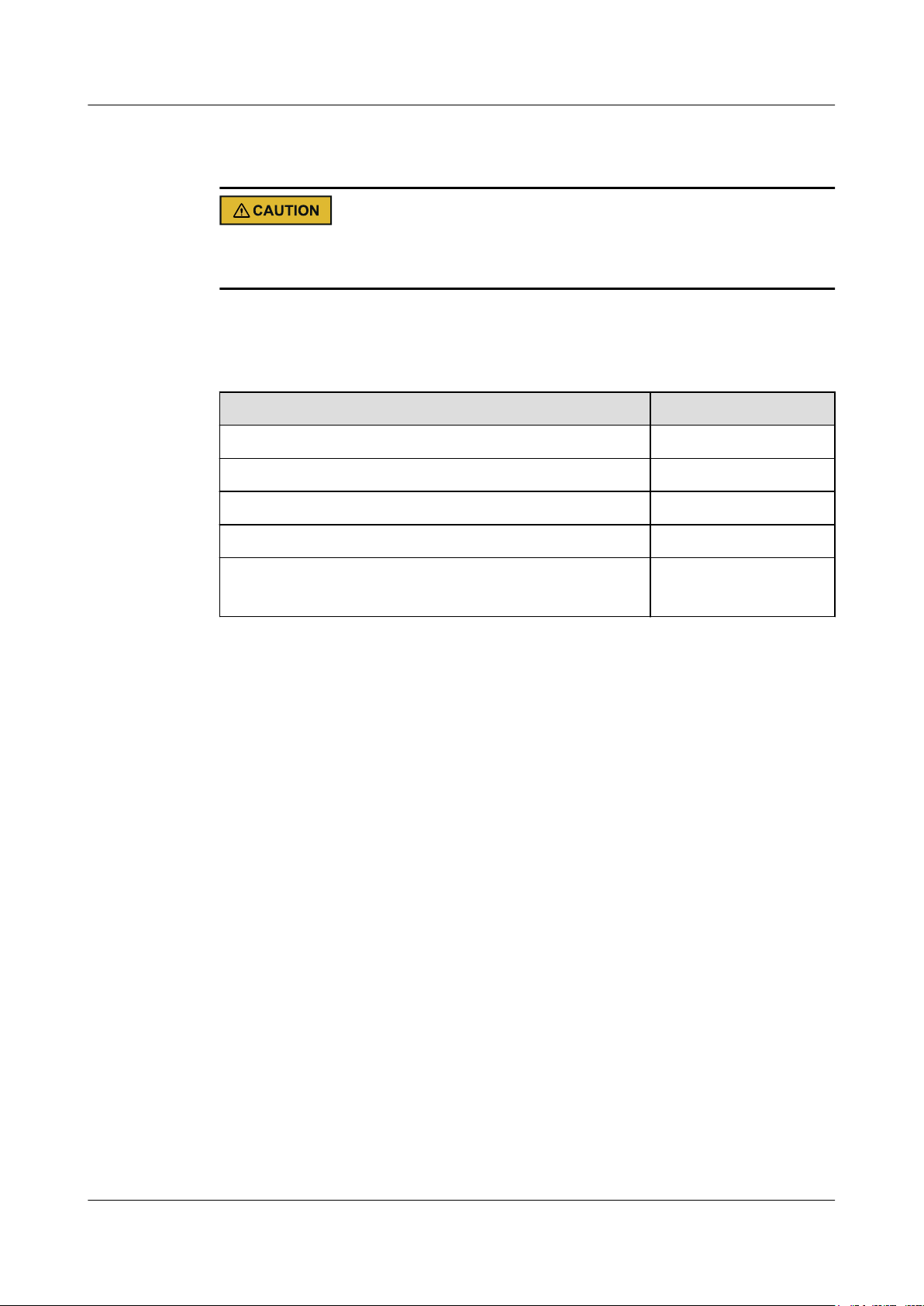
Maximum Load Carried by a Single Person
Comply with local regulations on the maximum load per person. The instructions on device
labels and in this document are for reference only.
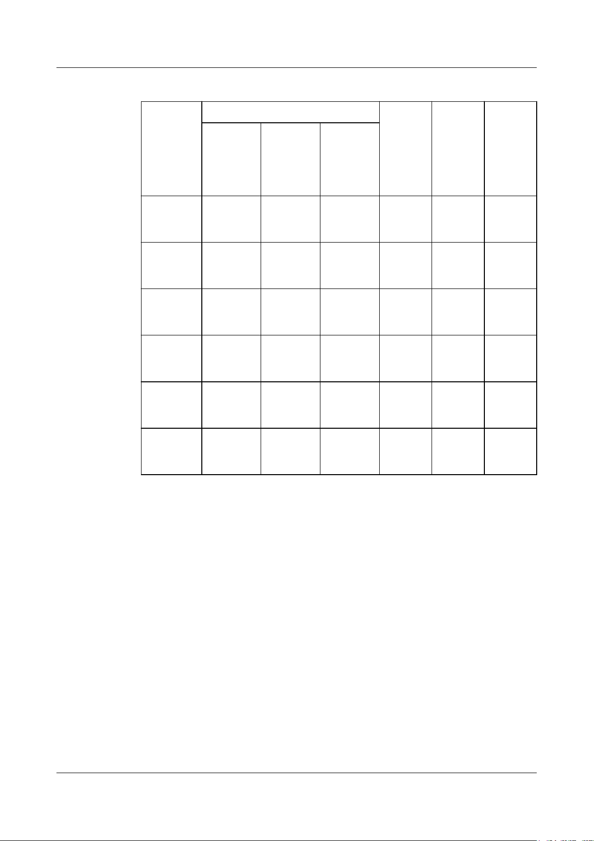
Table 1-1 lists the maximum weight each person is permitted to carry stipulated by related
organizations.
Table 1-1 Maximum handling weight
1 Safety Instructions
Organization
European Committee for Standardization (CEN) 25/55.13
International Organization for Standardization (ISO) 25/55.13
National Institute for Occupational Safety and Health (NIOSH) 23/50.72
Health and Safety Executive (HSE) 25/55.13
General Administration of Quality Supervision, Inspection and
Quarantine of the People's Republic of China (AQSIQ)
Weight (kg/lb)
l Male: 15/33.01
l Female: 10/22.05
Issue 32 (2019-03-28) Copyright © Huawei Technologies Co., Ltd. 4

RH2288 V3 Server
User Guide
About This Chapter
This section describes the features of the RH2288 V3.
2.1 Introduction
2 Overview
2 Overview
2.2 Appearance
2.3 Ports
2.4 Indicators and Buttons
2.5 Physical Structure
2.6 Mainboard Layout
2.7 Internal Cabling
2.8 Logical Structure
2.9 RAS Features
2.10 Software and Hardware Compatibility
2.11 Technical Specifications
2.12 Physical and Environmental Specifications
2.1 Introduction
The RH2288 V3 (marked as H22M-03 on the nameplate) is a 2U dual-socket rack server
launched by Huawei to meet customer requirements for the Internet, Internet data center
(IDC), cloud computing, enterprise market applications, and telecom service applications.
The RH2288 V3 features high-performance computing, large storage capacity, low power
consumption, and high scalability and reliability. It supports virtualization, and is easy to
manage and deploy. It is ideal for virtualization, basic enterprise applications, telecom
services, and storage services such as distributed storage, data mining, electronic albums, and
videos.
Table 2-1 describes the configurations of the RH2288 V3.
Issue 32 (2019-03-28) Copyright © Huawei Technologies Co., Ltd. 5
RH2288 V3 Server
User Guide
2 Overview
Table 2-1 RH2288 V3 configurations
ConfigurationMaximum Number of Front Disks Maximu
m
8-disk
Total Maximum
Number of
Common
[1][4]
Disks
[2]
8
8 - - 1 No
Maximum
Number of
NVMe
PCIe
[3][4]
SSDs
Number
of Rear
Common
[1]
Disks
configurati
on 1
8-disk
8 8 - - 1 Yes
configurati
on 2
12-disk
12 12 - 4 1 No
configurati
on 1
12-disk
configurati
12 12 (slots
0–11)
4 (slots
8–11)
- 1 No
on 2
24-disk
24
[2]
24 - configurati
on
Maximu
m
Number
of RAID
Controlle
r Cards
3
[7]
[5]
Support
for PCH
Configur
[6][7]
ation
No
25-disk
configurati
on
25
[2]
25 - 3 1 No
Issue 32 (2019-03-28) Copyright © Huawei Technologies Co., Ltd. 6
RH2288 V3 Server
User Guide
2 Overview
NOTE
2.5-inch or 3.5-inch indicates the size of a disk bay. A 2.5-inch disk bay can house a 2.5-inch disk, and a
3.5-inch disk bay can house a 2.5-inch or 3.5-inch disk.
[1]
l
: Common disks include SAS or SATA HDDs with 2.5-inch or 3.5-inch disk bays and SAS or
SATA SSDs with 2.5-inch disk bays.
[2]
l
: The front disk bays of 8-disk configuration 1, 24-disk configuration, and 25-disk
configuration can only be 2.5-inch.
[3]
l
: When NVMe PCIe SDDs are configured, related hardware, such as disk backplanes and riser
cards must be configured.
[4]
l
: Number of installed front disks = Number of installed front common disks + Number of installed
front NVMe PCIe SSDs.
The number of installed front disks on a server cannot be greater than the maximum number of front
disks. For example, 12-disk configuration 2 supports a maximum of 12 front disks. If four front
NVMe PCIe SSDs are installed, only a maximum of eight front common disks can be installed.
[5]
l
: For 24-disk configuration, a RAID controller card needs to be configured for every eight disks.
[6]
l
: The server where disks are connected through the Intel chipset (PCH) supports SATA disks only,
an optional SoftRAID license, and SoftRAID 0, 1, and 5. The server with SoftRAID configuration
does not support installation of a virtualization OS. If you have any doubts about the disk
configuration, contact your local Huawei sales representatives.
[7]
l
: Disks can be managed by the RAID controller card or the PCH. You can select only one of the
two management modes.
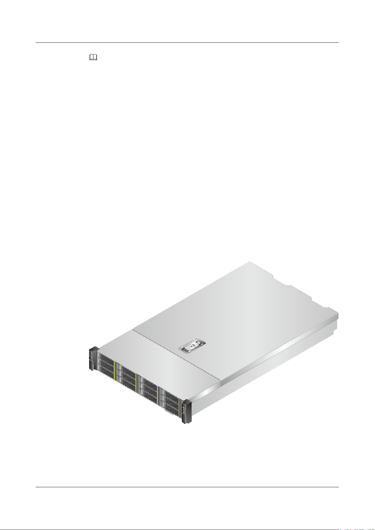
Figure 2-1 shows an RH2288 V3 with 12 disks.
Figure 2-1 RH2288 V3 with 12 disks
Issue 32 (2019-03-28) Copyright © Huawei Technologies Co., Ltd. 7
RH2288 V3 Server
User Guide
2.2 Appearance
Front Panel
Figure 2-2 shows the front panel of an RH2288 V3 with eight 2.5-inch hard disks.
Figure 2-2 Front panel of an RH2288 V3 with eight 2.5-inch hard disks
2 Overview
1 Fault diagnosis LED 2 Health indicator
3 UID button/indicator 4 Power button/indicator
5 Right mounting ear 6 VGA port
7 NMI button 8 Label plate with an ESN label
9 Built-in DVD drive 10 Hard disks (numbered 0 to 7 from left
to right)
11 USB 2.0 port 12 Left mounting ear
13 Network port link status indicators
(numbered 1 to 4 from top to bottom)
15 Hard disk activity indicator - -
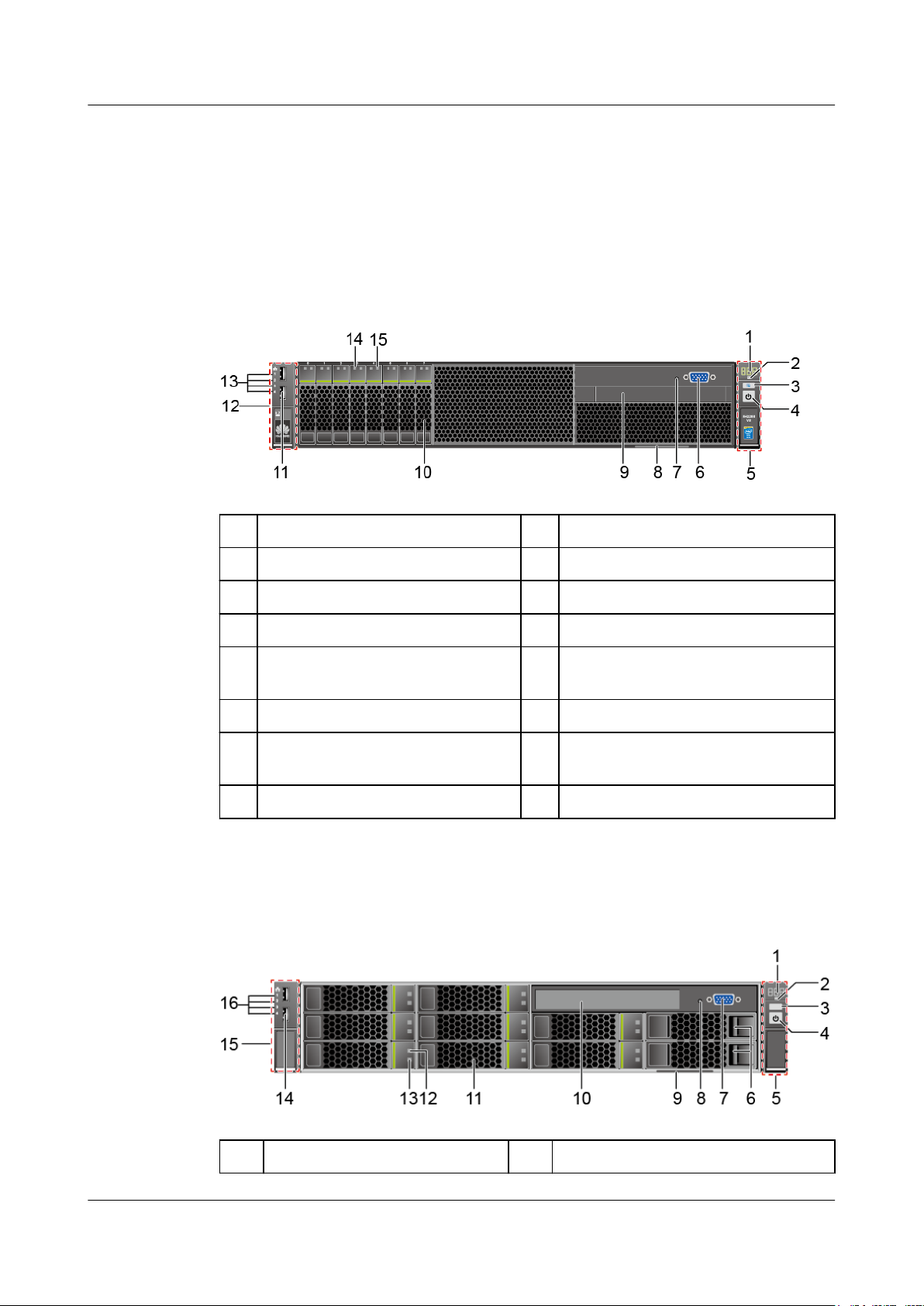
Figure 2-3 shows the front panel of an RH2288 V3 with eight 3.5-inch hard disks.
Figure 2-3 Front panel of an RH2288 V3 with eight 3.5-inch hard disks
14 Hard disk fault indicator
1
Fault diagnosis LED 2 Health indicator
Issue 32 (2019-03-28) Copyright © Huawei Technologies Co., Ltd. 8
RH2288 V3 Server
User Guide
2 Overview
3 UID button/indicator 4 Power button/indicator
5 Right mounting ear 6 Filler modules
NOTE
Do not install hard disks in the two slots.
7 VGA port 8 NMI button
9 Label plate with an ESN label 10 Built-in DVD drive
11 Hard disks (numbered 0 to 7 from
12 Hard disk fault indicator
top to bottom and from left to
right)
13 Hard disk activity indicator 14 USB 2.0 port
15 Left mounting ear 16 Network port link status indicators
(numbered 1 to 4 from top to bottom)
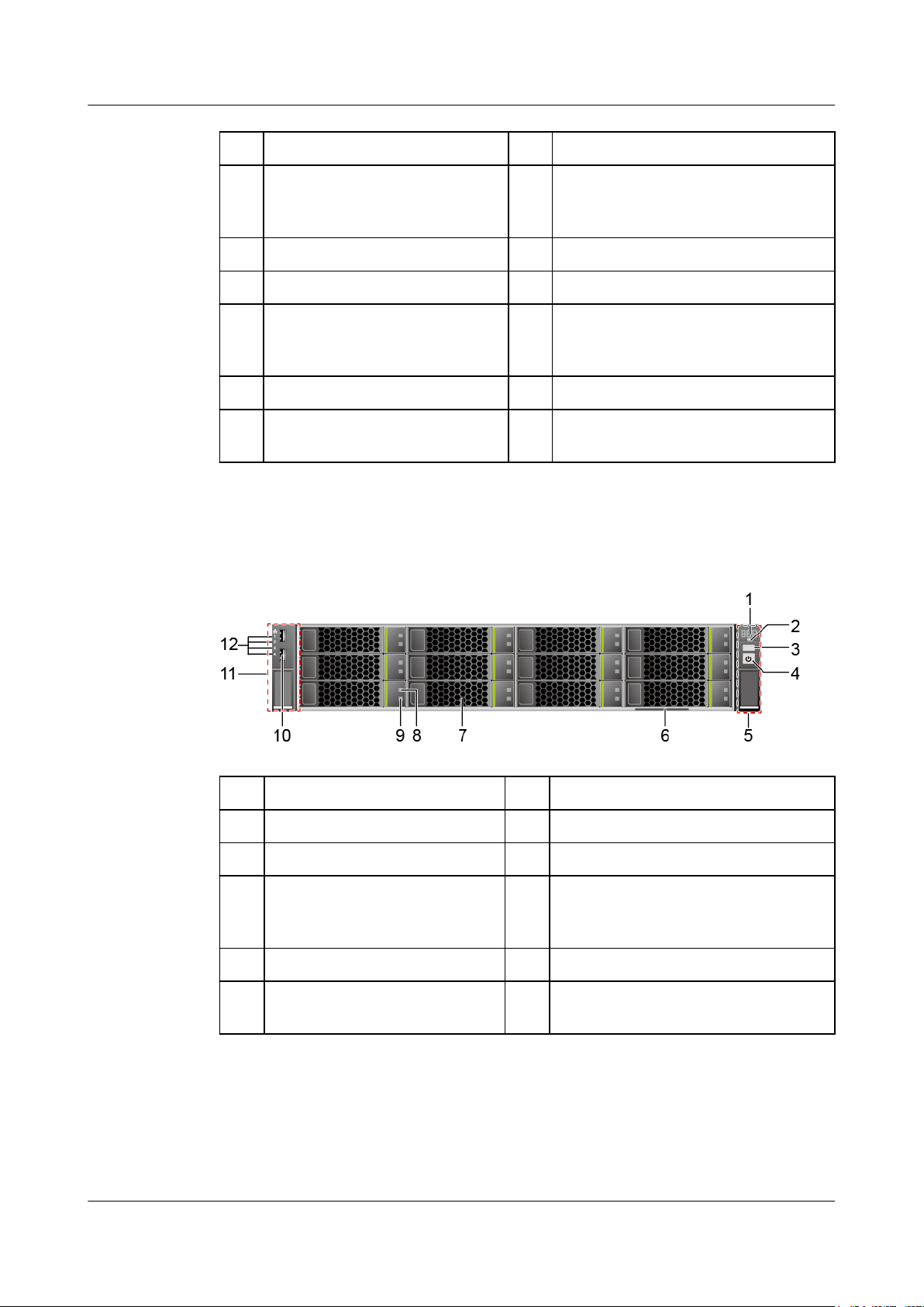
Figure 2-4 shows the front panel of an RH2288 V3 with twelve 3.5-inch hard disks.
Figure 2-4 Front panel of an RH2288 V3 with twelve 3.5-inch hard disks
1
Fault diagnosis LED 2 Health indicator
3 UID button/indicator 4 Power button/indicator
5 Right mounting ear 6 Label plate with an ESN label
7 Hard disks (numbered 0 to 11
8 Hard disk fault indicator
from top to bottom and from left
to right)
9 Hard disk activity indicator 10 USB 2.0 port
11 Left mounting ear 12 Network port link status indicators
(numbered 1 to 4 from top to bottom)
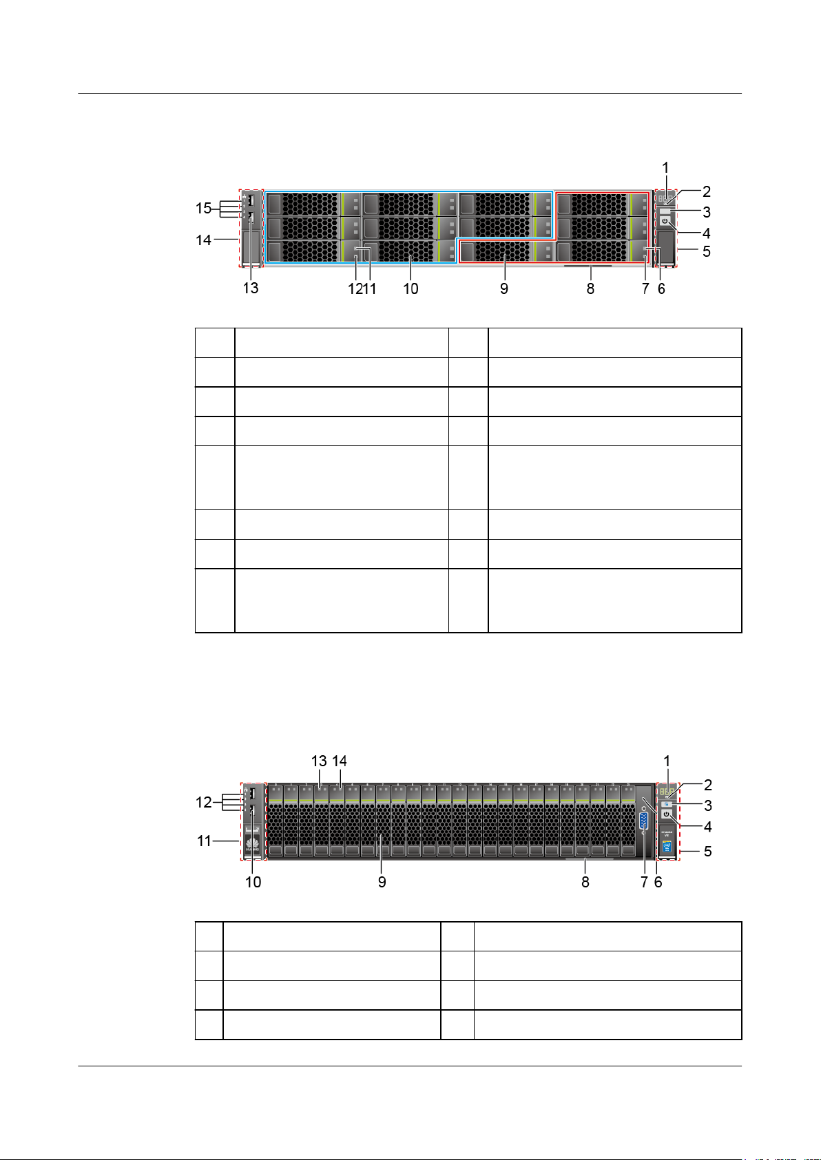
Figure 2-5 shows the front panel of an RH2288 V3 with twelve 3.5-inch hard disks, including
four NVMe PCIe SSDs.
Issue 32 (2019-03-28) Copyright © Huawei Technologies Co., Ltd. 9
RH2288 V3 Server
User Guide
2 Overview
Figure 2-5 Front panel of an RH2288 V3 with twelve 3.5-inch hard disks, including four
NVMe PCIe SSDs
1 Fault diagnosis LED 2 Health indicator
3 UID button/indicator 4 Power button/indicator
5 Right mounting ear 6 NVMe PCIe SSD yellow indicator
7 NVMe PCIe SSD green indicator 8 Label plate with an ESN label
9 NVMe PCIe SSDs (numbered 8
to 11 from left to right and from
10 Hard disks (numbered 0 to 7 from top to
bottom and from left to right)
top to bottom)
11 Hard disk fault indicator 12 Hard disk activity indicator
13 USB 2.0 port 14 Left mounting ear
15 Network port link status
- indicators (numbered 1 to 4 from
top to bottom)
Figure 2-6 shows the front panel of an RH2288 V3 with twenty-four 2.5-inch hard disks.
Figure 2-6 Front panel of an RH2288 V3 with twenty-four 2.5-inch hard disks
1
Fault diagnosis LED 2 Health indicator
3 UID button/indicator 4 Power button/indicator
5 Right mounting ear 6 NMI button
7 VGA port 8 Label plate with an ESN label
Issue 32 (2019-03-28) Copyright © Huawei Technologies Co., Ltd. 10
RH2288 V3 Server
User Guide
2 Overview
9 Hard disks (numbered 0 to 23
from left to right)
11Left mounting ear 12 Network port link status indicators
13Hard disk fault indicator 14 Hard disk activity indicator
Figure 2-7 shows the front panel of an RH2288 V3 with twenty-five 2.5-inch hard disks.
Figure 2-7 Front panel of an RH2288 V3 with twenty-five 2.5-inch hard disks
10 USB 2.0 port
(numbered 1 to 4 from top to bottom)
Rear Panel
1 Fault diagnosis LED 2 Health indicator
3 UID button/indicator 4 Power button/indicator
5 Right mounting ear 6 Label plate with an ESN label
7 Hard disks (numbered 0 to 24
from left to right)
9 Left mounting ear 10 Network port link status indicators
11Hard disk fault indicator 12 Hard disk activity indicator
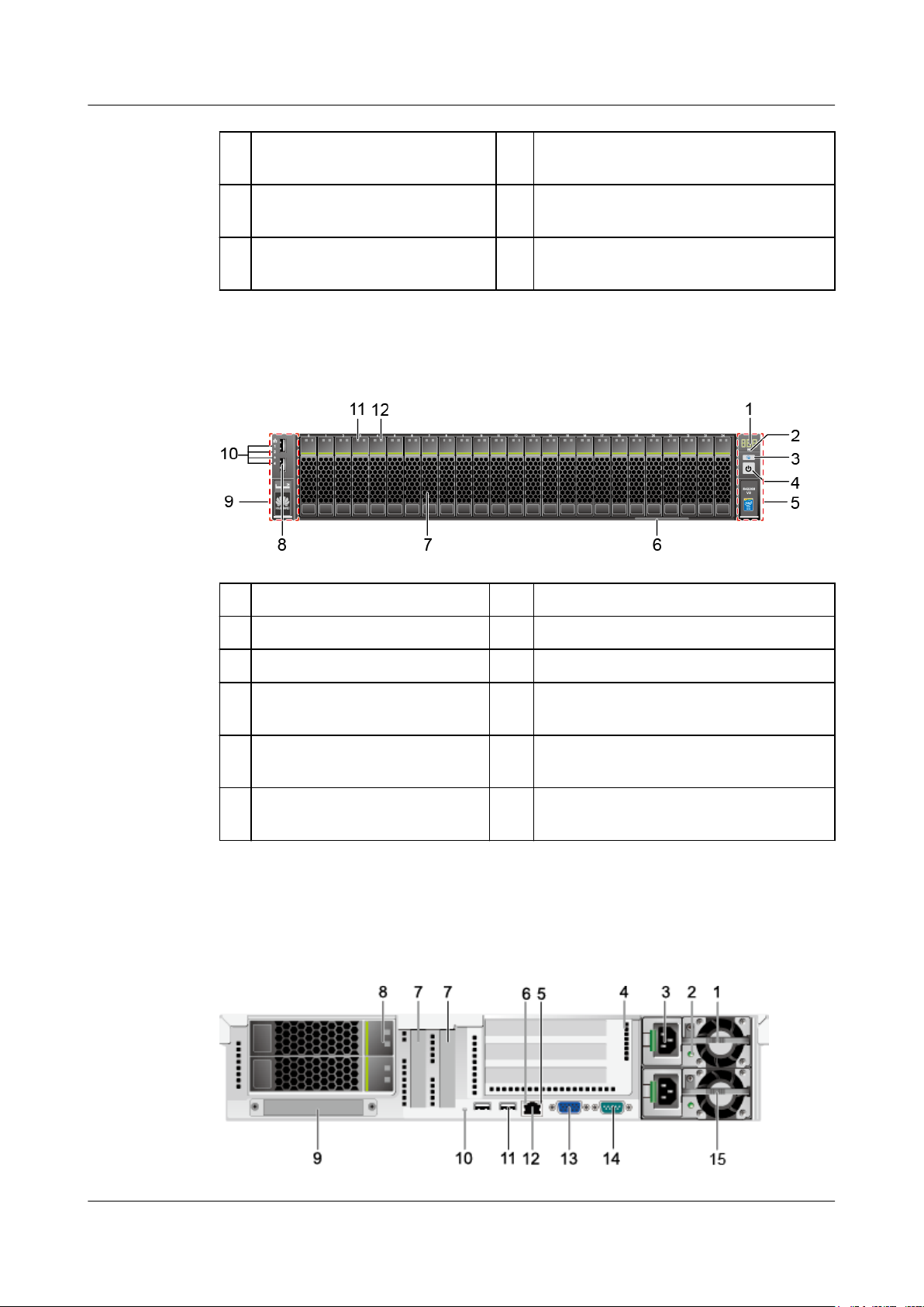
Figure 2-8 shows the rear panel of the RH2288 V3.
Figure 2-8 Rear panel of the RH2288 V3
8 USB 2.0 port
(numbered 1 to 4 from top to bottom)
Issue 32 (2019-03-28) Copyright © Huawei Technologies Co., Ltd. 11

RH2288 V3 Server
User Guide
2 Overview
1 PSU 1 2 PSU indicator
3 Power socket for a PSU 4 I/O module (providing slots 6 to 8 from
top to bottom) or NVMe PCIe SSD
adapter (corresponding to CPU 2,
providing slots 6 and 7 from top to
bottom)
5 Connection status indicator 6 Data transmission status indicator
7 Onboard PCIe slots (numbered
8 Hard disk
4 and 5 from left to right)
9 LAN on motherboard (flexible
10 UID indicator
NIC)
11 USB 3.0 port 12 Management network port
13 VGA port 14 Serial port
15 PSU 2 - -
NOTE
l Item 4 can be equipped with riser cards or rear 2.5-inch or 3.5-inch hard disks. Item 8 can be
equipped with 2.5-inch and 3.5-inch hard disks (2.5-inch and 3.5-inch hard disks can be configured
together).
l If the server is equipped with a front drive backplane connecting twelve 3.5-inch hard disks, you can
install a maximum of four 3.5-inch or 2.5-inch hard disks at the rear. Both items 8 and 4 can be
equipped with two 2.5-inch and 3.5-inch hard disks.
l If the server is equipped with a front drive backplane connecting twenty-five 2.5-inch hard disks,
you can install a maximum of three 3.5-inch or 2.5-inch hard disks at the rear. Item 8 can be
equipped with two hard disks, and item 4 can be equipped with only one hard disk in the upper slot.
l If item 8 is equipped with two hard disks, the disks are numbered A0 and B0 from top to bottom. If
item 4 is equipped with two hard disks, the disks are numbered A1 and B1 from top to bottom.
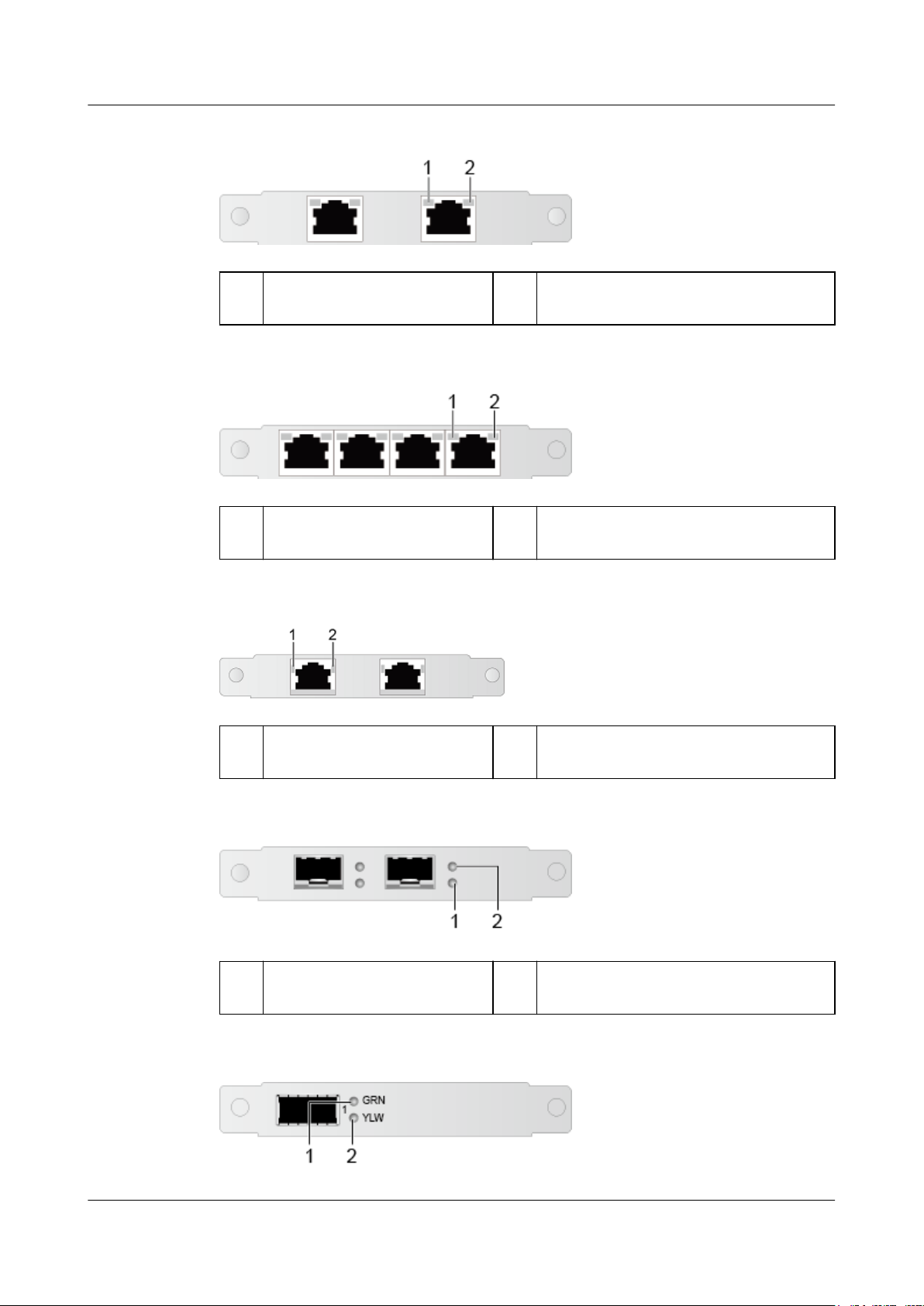
Flexible NICs
The RH2288 V3 supports the following models of flexible NICs:
l SM211: provides two GE electrical ports.
l SM210/SM212: provides four GE electrical ports.
l SM233: provides two 10GE electrical ports.
l SM231: provides two 10GE optical ports.
l SM252: provides one 56G IB optical port.
l SM251: provides two 56G IB optical ports.
NOTE
Use the Huawei Server Compatibility Checker to check flexible NICs supported by the server.
The following figures show flexible NIC ports and indicators.
Issue 32 (2019-03-28) Copyright © Huawei Technologies Co., Ltd. 12
RH2288 V3 Server
User Guide
2 Overview
Figure 2-9 SM211 ports and indicators
1 Data transmission status
2 Connection status indicator
indicator
Figure 2-10 SM210 or SM212 ports and indicators
1 Data transmission status
2 Connection status indicator
indicator
Figure 2-11 SM233 ports and indicators
1
Transmission rate indicator 2 Connection status indicator/Data
Figure 2-12 SM231 ports and indicators
1
Data transmission status
indicator
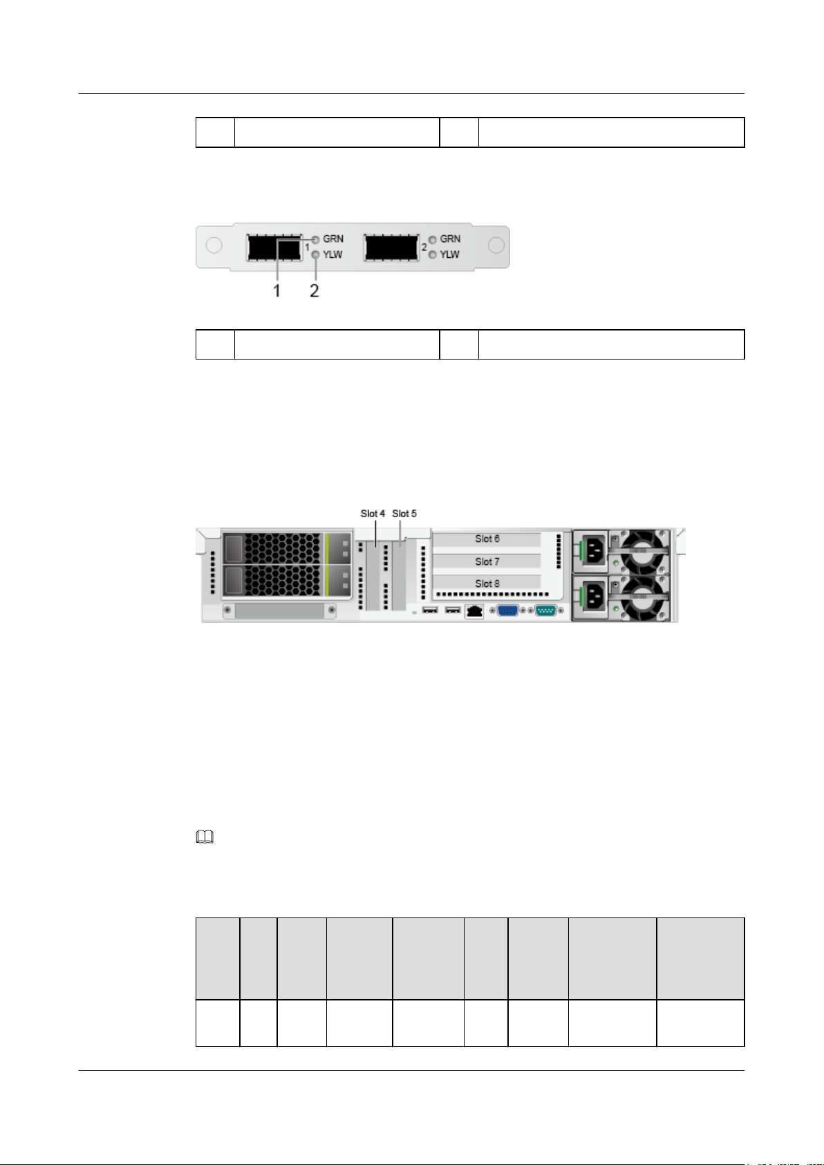
Figure 2-13 SM252 port and indicators
transmission status indicator
2 Connection status indicator
Issue 32 (2019-03-28) Copyright © Huawei Technologies Co., Ltd. 13
RH2288 V3 Server
User Guide
1 Connection status indicator 2 Data transmission status indicator
Figure 2-14 SM251 ports and indicators
1 Connection status indicator 2 Data transmission status indicator
PCIe Slot Layout
Figure 2-15 shows the PCIe slot layout of the RH2288 V3.
2 Overview
PCIe Devices
Figure 2-15 PCIe slot layout
The I/O module provides slots 6 to 8.
The I/O module supports 2-slot PCIe riser module or 3-slot PCIe riser module, but three slots
are always displayed on the panel. For a 2-slot PCIe riser module, slot 8 is unavailable.
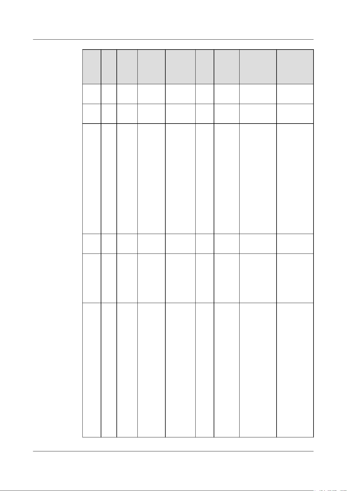
Table 2-2 describes the mapping between PCIe devices and CPUs, and the PCIe
specifications of the RH2288 V3.
NOTE
The PCIe devices mapping to a vacant CPU socket are unavailable.
Table 2-2 PCIe device description
PCI
e
Dev
ice
Slot4CP
Issue 32 (2019-03-28) Copyright © Huawei Technologies Co., Ltd. 14
CPUPCIe
Stan
dard
PCIe
U 1
3.0
Connec
tor
Width
Bus
Width
Port
Nu
mbe
r
Root
Port
(B/D/F
)
Device
(B/D/F)
Slot Size
x8 x8 Port3A00/03/0 04/00/0 Half-height
half-length
RH2288 V3 Server
User Guide
2 Overview
PCI
CPUPCIe
e
Dev
ice
Slot5CP
U 1
Slot6CP
U 2
Slot7CP
U 2
Stan
dard
PCIe
3.0
PCIe
3.0
PCIe
3.0
Connec
tor
Width
Bus
Width
Port
Nu
mbe
r
Root
Port
(B/D/F
)
Device
(B/D/F)
Slot Size
x8 x8 Port3C00/03/2 05/00/0 Half-height
half-length
x16 x8 Port1A80/01/0 81/00/0 Full-height
full-length
l 2-
slot
PCIe
riser
mod
ule:
x16
l 3-
slot
PCIe
riser
l 2-slot
PCIe
riser
modu
le:
x16
l 3-slot
PCIe
riser
modu
le: x8
Port2A80/02/0 82/00/0 Full-height
full-length
mod
ule:
x8
Slot8CP
U 2
RAI
D
CP
U 1
cont
rolle
r
card
Flex
ible
CP
U 1
NIC
PCIe
3.0
PCIe
3.0
PCIe
3.0
x8 x8 Port2C80/02/2 83/00/0 Full-height
half-length
x8 x8 Port1A00/01/0 01/00/0 —
x8 x8 Port2A00/02/0 A flexible
—
NIC with
four
network
ports is used
as an
example.
The four
network
port
numbers are
as follows:
l 02/00/0
l 02/00/1
l 02/00/2
l 02/00/3
Issue 32 (2019-03-28) Copyright © Huawei Technologies Co., Ltd. 15
RH2288 V3 Server
User Guide
2 Overview
PCI
e
Dev
ice
Note 1: B/D/F stands for Bus/Device/Function Number.
Note 2: Root Port (B/D/F) indicates the bus number of a CPU internal PCIe root port.
Device (B/D/F) indicates the bus number (displayed on the OS) of an onboard or external
PCIe port.
Note 3: The PCIe slots that support full-height full-length PCIe cards are backward
compatible with full-height half-length or half-height half-length PCIe cards.
Note 4: The PCIe slots with the bus width of PCIe x16 are backward compatible with PCIe
x8, PCIe x4, and PCIe x1 cards.
Note 5: All slots support PCIe cards of up to 75 W. The power of a PCIe card varies
depending on its model. Use the Huawei Server Compatibility Checker to check
supported PCIe cards. For PCIe cards not listed in the Huawei Server Compatibility
Checker, contact your local Huawei sales personnel.
Note 6: This table lists the default values of B/D/F. If thePCIe sockets are not fully
populated or a PCIe card with a PCI bridge is configured, the values of B/D/F may differ.
Note 7: For a server with NVMe PCIe SSDs, a 2-slot riser module must be installed on the
I/O module and an NVMe PCIe SSD adapter can be installed only in slot 7.
CPUPCIe
Stan
dard
Connec
tor
Width
Bus
Width
Port
Nu
mbe
r
Root
Port
(B/D/F
)
Device
(B/D/F)
Slot Size
PCIe GPU Configuration Guidelines
A GPU must be installed on a PCIe riser module.
l A 2-slot PCIe riser module supports one single-slot or dual-slot PCIe x16 GPU, which is
installed in slot 7.
l A 3-slot PCIe riser module does not support any GPU.
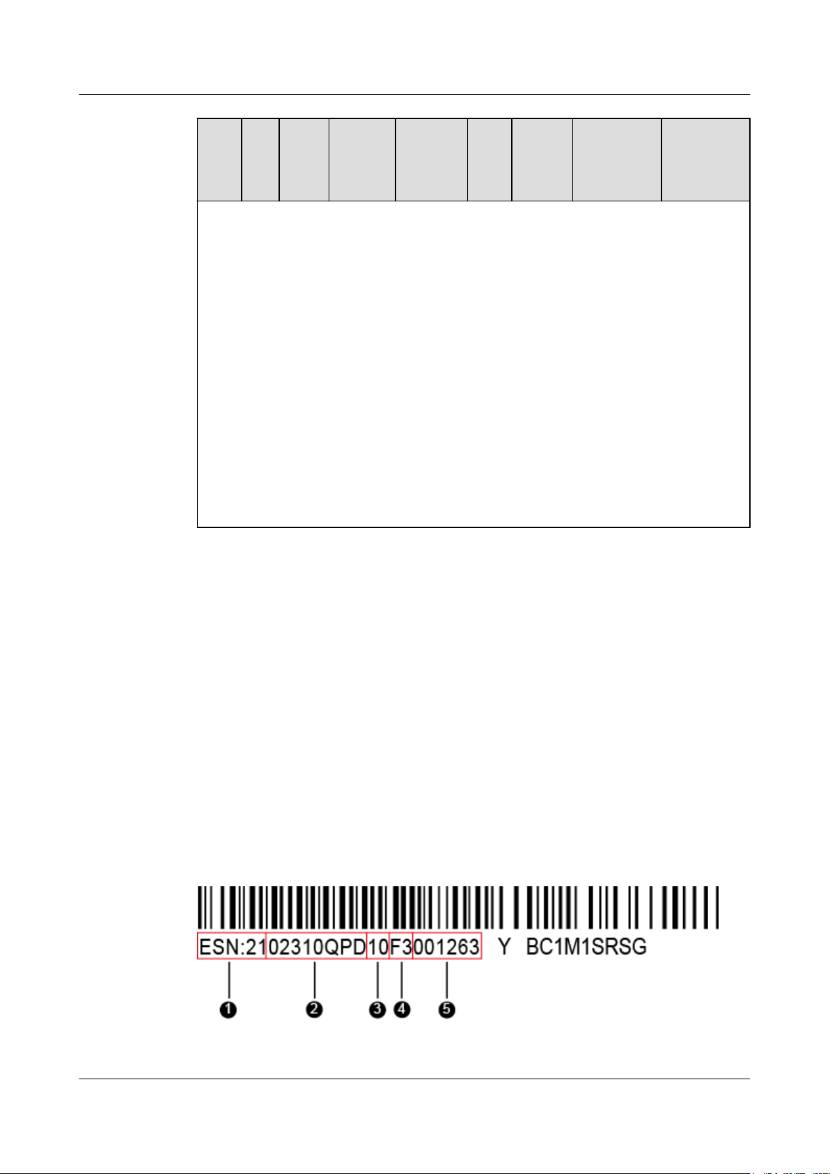
ESNs
An Equipment Serial Number (ESN) is a string that uniquely identifies a server. An ESN is
required when you apply for technical support from Huawei.
Figure 2-16 shows the ESN format by using the example 2102310QPD10F3001263.
Figure 2-16 ESN example
Issue 32 (2019-03-28) Copyright © Huawei Technologies Co., Ltd. 16
RH2288 V3 Server
User Guide
2.3 Ports
2 Overview
No. Description
1 Indicates the ESN ID.
2 Indicates the material identification code
(eight characters).
3 Indicates the vendor code (two characters).
4 Indicates the year and month (two
characters).
5 Indicates the serial number (six characters).
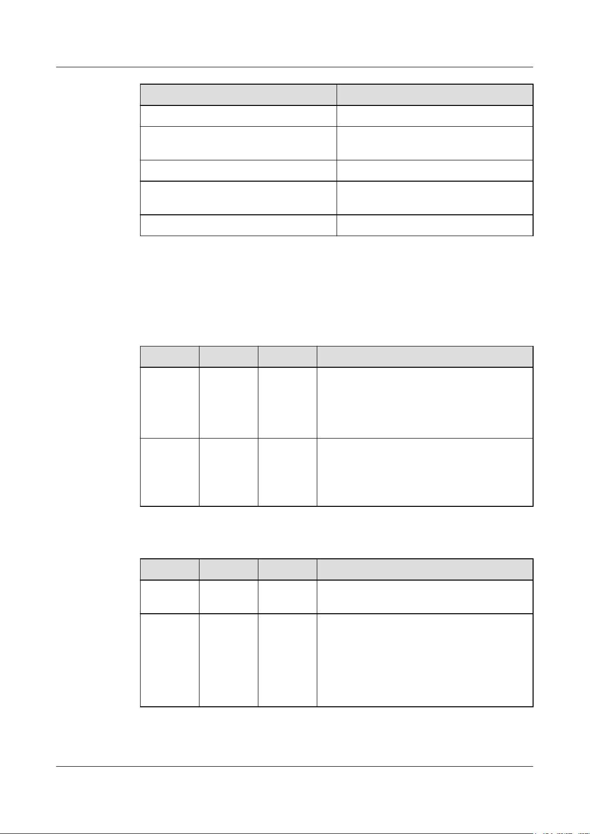
Table 2-3 and Table 2-4 describe the external ports on the RH2288 V3.
Table 2-3 Ports on the front panel
Port
Video
graphics
Type Quantity Description
DB15 1 The VGA port is used to connect a terminal,
such as a monitor or KVM.
array
(VGA)
port
USB port USB 2.0 2 The USB ports are connected to USB devices.
NOTE
Before connecting to an external USB device, check
that the USB device operates properly. A server may
fail if it is connected to an abnormal USB device.
Table 2-4 Ports on the rear panel
Port
Type Quantity Description
VGA port DB15 1 The VGA port is used to connect a terminal,
such as a monitor or KVM.
USB port USB 3.0 2 The USB ports are connected to USB devices.
NOTE
Before connecting to an external USB device, check
that the USB device operates properly. A server may
fail if it is connected to an abnormal USB device.
USB 3.0 is disabled by default. You can enable it on
the BIOS as required.
Issue 32 (2019-03-28) Copyright © Huawei Technologies Co., Ltd. 17
RH2288 V3 Server
User Guide
2 Overview
Port Type Quantity Description
Manageme
nt network
Ethernet
port
port
(Mgmt)
Serial port DB9 1 Three-pin serial port. The default baud rate is
Network
- - The port types and quantity vary according to the
port
2.4 Indicators and Buttons
Front Panel
You can observe the indicators to determine the status of the RH2288 V3.
1 The 1000 Mbit/s Ethernet port is used to manage
the server.
115200 bits/s.
The serial port is used as the system serial port
by default. You can set it as the iBMC serial port
by using the iBMC command. The port is used
for debugging.
flexible NIC configured.
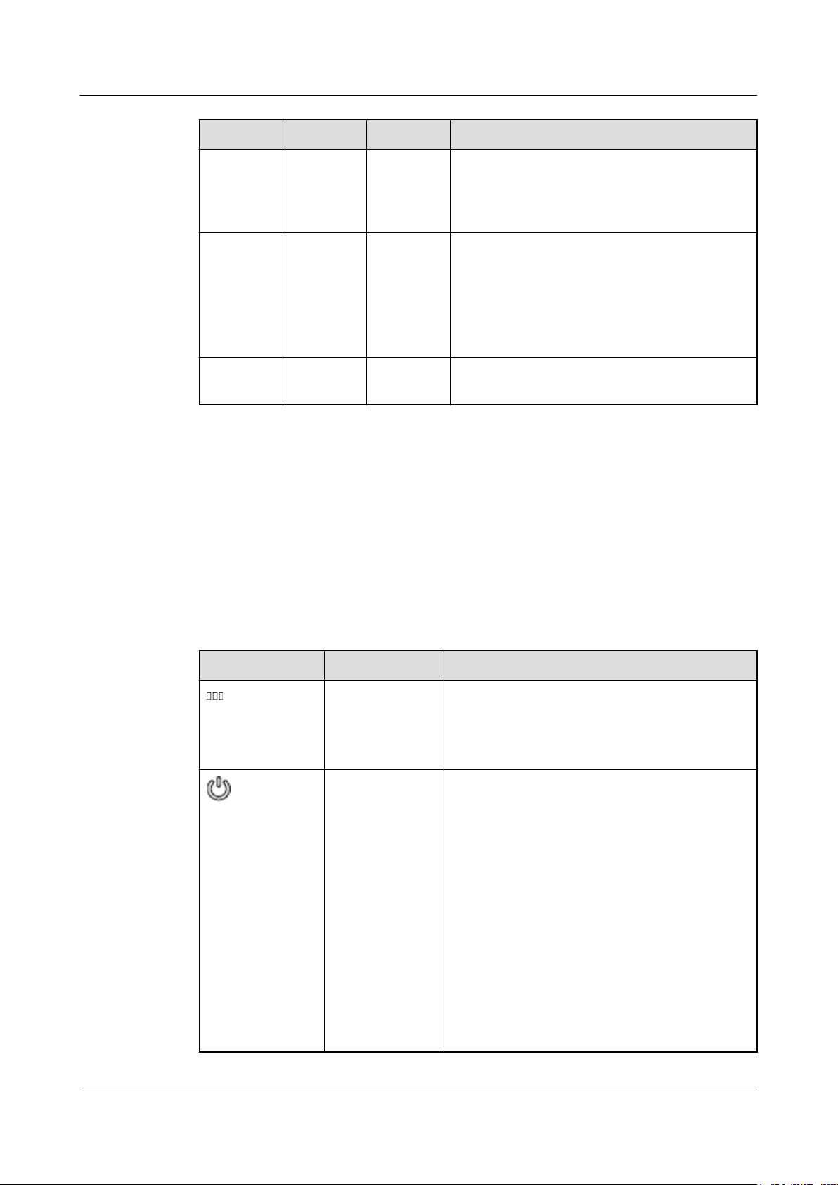
Table 2-6 describes the indicators and buttons on the RH2288 V3 front panel.
Table 2-5 Indicators and buttons on the front panel
Silkscreen
Meaning State Description
Fault diagnosis
LED
l ---: The server is operating properly.
l Error code: A fault occurs in server hardware.
For details about error codes, see Huawei
Rack Server Alarm Handling (iBMC).
Power button/
indicator
l Off: The server is not connected to a power
source.
l Blinking yellow: The iBMC is starting.
l Steady yellow: The server is ready to power
on.
l Steady green: The system is properly powered
on.
NOTE
l When the server is powered on, you can press this
button to shut down the OS.
l When the server is powered on, you can hold down
this button for 6 seconds to power off the server.
l When the server is ready to power on, you can press
this button to start the server.
Issue 32 (2019-03-28) Copyright © Huawei Technologies Co., Ltd. 18
 Loading...