

Huawei Quidway Eudemon 200 Installation Manual

Chapter 1 Overview 1-1.........................................................................................
1.1 Introduction to the Eudemon200 Firewall 1-1...............................................
1.2 Product Structure 1-3...................................................................................
1.3 System Parameters 1-5................................................................................
1.4 Introduction to General Modules 1-6............................................................
1.4.1 RPU 1-6...............................................................................................
1.4.2 PWR 1-9...............................................................................................
1.4.3 FAN 1-11................................................................................................
1.4.4 Interface Module 1-12............................................................................
Chapter 2 Installation Preparation 2-1.................................................................
2.1 Site Inspection 2-1........................................................................................
2.1.1 Equipment Room Environment 2-1......................................................
2.1.2 ESD Protection 2-1..............................................................................
2.1.3 Electromagnetic Environment 2-2........................................................
2.1.4 Lightning Protection 2-2.......................................................................
2.1.5 Workbench 2-3.....................................................................................
2.2 Safety Recommendations 2-3......................................................................
2.3 Checking Eudemon200 and Accessories 2-3...............................................
2.4 Installation Tools, Meters and Equipment 2-5..............................................
Chapter 3 Installation 3-1......................................................................................
3.1 Installation Flow 3-1......................................................................................
3.2 Mount a Eudemon200 to a Specified Place 3-2...........................................
3.2.1 Mounting a Eudemon200 into the Rack 3-2.........................................
3.2.2 Mount a Eudemon200 onto the Workbench 3-3..................................
3.3 Connect the PGND 3-3.................................................................................
3.4 Connect Power Cable 3-4............................................................................
3.4.1 Connect AC Power Cable 3-4..............................................................
3.4.2 Connect DC-Input Power Cable 3-5.....................................................
3.5 Connect the Console Terminal 3-7...............................................................
3.6 Connect the Eudemon200 to LAN 3-8..........................................................
3.7 Connect the Eudemon200 to WAN 3-9........................................................
3.8 Verify Installation 3-11....................................................................................
Chapter 4 Boot and Configuration 4-1.................................................................
4.1 Boot the Eudemon200 4-1............................................................................
4.1.1 Establish Configuration Environment 4-1.............................................
4.1.2 Power on the Eudemon200 4-4...........................................................
4.1.3 Startup Process 4-5.............................................................................
4.2 Configuration Fundamentals 4-7..................................................................

4.2.1 Basic Configuration Procedure 4-7......................................................
4.2.2 Command Line Interface 4-8................................................................
4.2.3 Slot Arrangement and Interface Numbering Rules 4-9........................
4.3 Software Maintenance 4-9............................................................................
Chapter 5 Hardware Maintenance 5-1..................................................................
5.1 Tools Required 5-1.......................................................................................
5.2 Power Module Removal and Installation 5-1................................................
5.2.1 Remove a Power Module 5-1...............................................................
5.2.2 Install a Power Module 5-2...................................................................
5.3 Fan Removal and Installation 5-2.................................................................
5.3.1 Remove a Fan 5-2...............................................................................
5.3.2 Install a Fan 5-3...................................................................................
5.4 RPU Removal and Installation 5-4...............................................................
5.4.1 Remove an RPU 5-4............................................................................
5.4.2 Install an RPU 5-4................................................................................
5.5 Replace an SDRAM 5-4...............................................................................
Chapter 6 Troubleshooting 6-1.............................................................................
6.1 Troubleshooting of the Power System 6-1...................................................
6.2 Troubleshooting of the Configuration System 6-1........................................
6.3 Troubleshooting of Application Software Upgrade 6-2.................................
Chapter 7 Interface Module 7-1.............................................................................
7.1 Interface Module Category 7-1.....................................................................
7.2 Remove and Install Interface Module 7-1.....................................................
7.3 Troubleshooting 7-2......................................................................................
7.4 1FE/2FE 7-3.................................................................................................
7.4.1 Introduction 7-3....................................................................................
7.4.2 Interface Attributes 7-3.........................................................................
7.4.3 Panel and Interface LED 7-4................................................................
7.4.4 Interface Cable 7-4...............................................................................
7.4.5 Connect Interface Cable 7-5................................................................
7.5 1MFX/1SFX 7-5............................................................................................
7.5.1 Introduction 7-5....................................................................................
7.5.2 Interface Attributes 7-6.........................................................................
7.5.3 Panel and Interface LED 7-7................................................................
7.5.4 Interface Optical Fiber 7-7....................................................................
7.5.5 Connect Interface Optical Fiber 7-8.....................................................
7.6 4E1 7-9.........................................................................................................
7.6.1 Introduction 7-9....................................................................................
7.6.2 Interface Attributes 7-9.........................................................................

7.6.3 Panel and Interface LED 7-10................................................................
7.6.4 Interface Cable of 4E1 7-10...................................................................
7.6.5 Internal DIP Switch 7-12........................................................................
7.6.6 Connect Interface Cable 7-13................................................................
7.7 4T1 7-14.........................................................................................................
7.7.1 Introduction 7-14....................................................................................
7.7.2 Interface Attributes 7-14.........................................................................
7.7.3 Panel and Interface LED 7-15................................................................
7.7.4 Interface Cable 7-15...............................................................................
7.7.5 Connect Interface Cable 7-16................................................................
7.8 1ATM-OC3MM /1ATM-OC3SM/1ATM-OC3SML 7-17...................................
7.8.1 Introduction 7-17....................................................................................
7.8.2 Interface Attributes 7-18.........................................................................
7.8.3 Panel and Interface LED 7-18................................................................
7.8.4 Interface Optical Fiber 7-19....................................................................
7.8.5 Connecting Interface Optical Fiber 7-20................................................
Appendix A Specifications of Interface Cables A-1............................................
A.1 Console Cable A-1.......................................................................................
A.2 AUX Cable A-1.............................................................................................
A.3 Ethernet Cable Pinouts A-2..........................................................................
A.3.1 RJ45 Connector A-2.............................................................................
A.3.2 Category 5 Twisted Pair A-2................................................................
A.3.3 Ethernet Cable Pinouts A-3..................................................................
A.4 E1 Cable and 4E1 Conversion Cable A-4....................................................
A.5 T1 Cable A-6................................................................................................

HUAWEI
Quidway Eudemon 200 Firewall
Installation Manual

Quidway Eudemon 200 Firewall
Installation Manual
Manual Version
T2-080477-20040323-C-1.01
BOM
31040977
Huawei Technologies Co., Ltd. provides customers with comprehensive technical support
and service. If you purchase the products from the sales agent of Huawei Technologies Co.,
Ltd., please contact our sales agent. If you purchase the products from Huawei
Technologies Co., Ltd. directly, Please feel free to contact our local office, customer care
center or company headquarters.
Huawei Technologies Co., Ltd.
Ad dress: Administration Building, Huawei Technologies Co., Ltd.,
Bantian, Longgang District, Shenzhen, P. R. China
Postal Code: 518129
Website: http://www.huawei.com

Copyright © 2004 Huawei Technologies Co., Ltd.
All Rights Reserved
No part of this manual may be reproduced or transmitted in any form or by any
means without prior written consent of Huawei Technologies Co., Ltd.
Trademarks
, HUAWEI, C&C08, EAST8000, HONET, , ViewPoint, INtess, ETS, DMC,
TELLIN, InfoLink, Netkey, Quidway, SYNLOCK, Radium,
M900/M1800,
TELESIGHT, Quidview, Musa, Airbridge, Tellwin, Inmedia, VRP, DOPRA, iTELLIN,
HUAWEI OptiX, C&C08
iNET, NETENGINE, OptiX, iSite, U-SYS, iMUSE, OpenEye,
Lansway, SmartAX, infoX, TopEng are trademarks of Huawei Technologies Co.,
Ltd.
All other trademarks mentioned in this manual are the property of their respective
holders.
Notice
The information in this manual is subject to change without notice. Every effort has
been made in the preparation of this manual to ensure accuracy of the contents, but
all statements, information, and recommendations in this manual do not constitute
the warranty of any kind, express or implied.

About This Manual
Release Notes
The product corresponding to this manual is Quidway Eudemon 200 Firewall.
Related Manuals
The following manuals provide more information about Quidway Eudemon 200 Firewall
VRP3.20.
Manual Content
Quidway Eudemon 200 Firewall
Installation Manual
It provides information for the installation of Eudemon200
Firewall, boot and configuration, software and hardware
maintenance, troubleshooting and monitoring.
Quidway Eudemon Series Firewall
Operation Manual
It introduces the information about Eudemon Series
firewalls such as getting started, system management,
security defense, VPN and QoS. In addition, it also provides
the operation guide for the network interconnection.
Quidway Eudemon Series Firewall
Command Manual
It provides the commands of Eudemon Series firewalls such
as management, security defense, upper layer service and
network interconnection.
Organization of the Manual
In Quidway Eudemon200 Firewall Installation Manual, the chapters are arranged as
follows:
• Chapter 1 Overview
Introduces briefly the structure and hardware specification of Eudemon 200
• Chapter 2 Installation Preparation
Covers the safety advice, site requirements and tools for installation.
• Chapter 3 Installation
Detailes installation of Eudemon 200, connection of various cables.
• Chapter 4 Boot and Configuration

Describes the boot and configuration essentials of Eudemon 200 simple application of
command lines, list of interface configuration modes and introduction to names and
sequences of interfaces.
• Chapter 5 Hardware Maintenance
Gives the hardware maintenance, including replacement of power module, blower
module and various boards of Eudemon 200.
• Chapter 6 Troubleshooting
Introduces the common fault diagnosis and troubleshooting of Eudemon 200.
• Chapter 7 Interface Module
Deals with the structure, profile, function, interface, indicator and connection cables of
various network interface modules of Eudemon 200.
• Appendix
Describes the internal connection of related cables.
Intended Readers
The manual is intended for the following readers:
z Network engineers
z Network administrators
z Customers who are familiar with network fundamentals
Conventions
This document uses the following conventions:
I. General conventions
Convention Description
Arial Normal paragraphs are in Arial.
Arial Narrow Warnings, Cautions, Notes and Tips are in Arial Narrow.
Boldface Headings are in Boldface.
Courier New
Terminal Display is in Courier New.

II. Command conventions
Convention Description
boldface font Command keywords (which must be input unchanged) are in boldface.
italic font Command arguments for which you supply values are in italics.
[ ] Elements in square brackets [ ] are optional.
!
A line starting with an exclamation mark is comments.
III. Symbols
Eye-catching symbols are also used in this document to highlight the points worthy of
special attention during the operation. They are defined as follows:
Caution, Warning: Means reader be extremely careful during the operation.
Note: Means a complementary description.
Environmental Protection
This product has been designed to comply with the requirements on environmental
protection. For the proper storage, use and disposal of this product, national laws and
regulations must be observed.

Installation Manual
Quidway Eudemon 200 Firewall Table of Contents
i
Table of Contents
Chapter 1 Overview ....................................................................................................................... 1-1
1.1 Brief Introduction to Eudemon200 ..................................................................................... 1-1
1.2 Product Structure ............................................................................................................... 1-3
1.3 System parameter ............................................................................................................. 1-5
1.4 Introduction to General Modules........................................................................................ 1-5
1.4.1 RPU......................................................................................................................... 1-6
1.4.2 PWR ........................................................................................................................ 1-8
1.4.3 FAN .......................................................................................................................1-10
1.4.4 Interface Module ................................................................................................... 1-11
Chapter 2 Installation Preparation............................................................................................... 2-1
2.1 Site Inspection ................................................................................................................... 2-1
2.1.1 Equipment Room Environment ............................................................................... 2-1
2.1.2 ESD Protection........................................................................................................ 2-1
2.1.3 Electromagnetic Environment ................................................................................. 2-2
2.1.4 Lightning Protection ................................................................................................ 2-2
2.1.5 Workbench.............................................................................................................. 2-3
2.2 Safety Recommendations.................................................................................................. 2-3
2.3 Checking Eudemon200 and Accessories.......................................................................... 2-3
2.4 Installation Tools, Meters and Equipment ......................................................................... 2-5
Chapter 3 Installation .................................................................................................................... 3-1
3.1 Installation Flow ................................................................................................................. 3-1
3.2 Mount a Eudemon200 to a Specified Place ...................................................................... 3-2
3.2.1 Mounting a Eudemon200 into the Rack .................................................................. 3-2
3.2.2 Mount a Eudemon200 onto the Workbench ........................................................... 3-3
3.3 Connect the PGND ............................................................................................................3-3
3.4 Connect Power Cable ........................................................................................................ 3-4
3.4.1 Connect AC Power Cable ....................................................................................... 3-4
3.4.2 Connect DC-Input Power Cable.............................................................................. 3-5
3.5 Connect the Console Terminal .......................................................................................... 3-7
3.6 Connect the Eudemon200 to LAN..................................................................................... 3-8
3.7 Connect the Eudemon200 to WAN ................................................................................... 3-9
3.8 Verify Installation ............................................................................................................. 3-11
Chapter 4 Boot and Configuration............................................................................................... 4-1
4.1 Boot the Eudemon200 ....................................................................................................... 4-1
4.1.1 Establish Configuration Environment...................................................................... 4-1
4.1.2 Power on the Eudemon200..................................................................................... 4-4

Installation Manual
Quidway Eudemon 200 Firewall Table of Contents
ii
4.1.3 Startup Process....................................................................................................... 4-5
4.2 Configuration Fundamentals.............................................................................................. 4-7
4.2.1 Basic Configuration Procedure ............................................................................... 4-7
4.2.2 Command Line Interface......................................................................................... 4-8
4.2.3 Slot Arrangement and Interface Numbering Rules ................................................. 4-9
4.3 Software Maintenance ....................................................................................................... 4-9
Chapter 5 Hardware Maintenance................................................................................................ 5-1
5.1 Prepare Tools .................................................................................................................... 5-1
5.2 Power Module Removal and Installation ........................................................................... 5-1
5.2.1 Remove a Power Module........................................................................................ 5-1
5.2.2 Install a Power Module............................................................................................ 5-2
5.3 Fan Removal and Installation ............................................................................................ 5-2
5.3.1 Remove a Fan......................................................................................................... 5-2
5.3.2 Install a Fan.............................................................................................................5-3
5.4 RPU Removal and Installation........................................................................................... 5-3
5.4.1 Remove an RPU ..................................................................................................... 5-3
5.4.2 Install an RPU ......................................................................................................... 5-4
5.5 Replace SDRAM................................................................................................................ 5-4
Chapter 6 Troubleshooting .......................................................................................................... 6-1
6.1 Troubleshooting of the Power System............................................................................... 6-1
6.2 Troubleshooting of the Configuration System ................................................................... 6-1
6.3 Troubleshooting of Application Software Upgrade ............................................................ 6-2
Chapter 7 Interface Module .......................................................................................................... 7-1
7.1 Interface Module Category ................................................................................................ 7-1
7.2 Remove and Install Interface Module ................................................................................ 7-1
7.3 Troubleshooting ................................................................................................................. 7-2
7.4 1FE/2FE............................................................................................................................. 7-3
7.4.1 Introduction..............................................................................................................7-3
7.4.2 Interface Attributes .................................................................................................. 7-3
7.4.3 Panel and Interface LED......................................................................................... 7-4
7.4.4 Interface Cable ........................................................................................................ 7-4
7.4.5 Connect Interface Cable ......................................................................................... 7-5
7.5 1MFX/1SFX ....................................................................................................................... 7-5
7.5.1 Introduction..............................................................................................................7-5
7.5.2 Interface Attributes .................................................................................................. 7-6
7.5.3 Panel and Interface LED......................................................................................... 7-7
7.5.4 Interface Optical Fiber............................................................................................. 7-7
7.5.5 Connect Interface Optical Fiber .............................................................................. 7-8
7.6 4E1..................................................................................................................................... 7-9
7.6.1 Introduction..............................................................................................................7-9
7.6.2 Interface Attributes .................................................................................................. 7-9

Installation Manual
Quidway Eudemon 200 Firewall Table of Contents
iii
7.6.3 Panel and Interface LED....................................................................................... 7-10
7.6.4 Interface Cable of 4E1 .......................................................................................... 7-10
7.6.5 Internal DIP Switch................................................................................................ 7-12
7.6.6 Connect Interface Cable ....................................................................................... 7-13
7.7 4T1................................................................................................................................... 7-14
7.7.1 Introduction............................................................................................................ 7-14
7.7.2 Interface Attributes ................................................................................................ 7-14
7.7.3 Panel and Interface LED....................................................................................... 7-15
7.7.4 Interface Cable ...................................................................................................... 7-15
7.7.5 Connect Interface Cable ....................................................................................... 7-16
7.8 1ATM-OC3MM/1ATM-OC3SM/1ATM-OC3SML ............................................................. 7-17
7.8.1 Introduction............................................................................................................ 7-17
7.8.2 Interface Attributes ................................................................................................ 7-18
7.8.3 Panel and Interface LED....................................................................................... 7-18
7.8.4 Interface Optical Fiber........................................................................................... 7-19
7.8.5 Connecting Interface Optical Fiber ....................................................................... 7-20
Appendix A Specifications of Interface Cables..........................................................................A-1
A.1 Console Cable ................................................................................................................... A-1
A.2 AUX Cable.........................................................................................................................A-1
A.3 Ethernet Cable Pinouts .....................................................................................................A-2
A.3.1 RJ45 Connector ...................................................................................................... A-2
A.3.2 Category 5 Twisted Pair ......................................................................................... A-2
A.3.3 Ethernet Cable Pinouts........................................................................................... A-3
A.4 E1 Cable and 4E1 Conversion Cable ............................................................................... A-4
A.5 T1 Cable ............................................................................................................................ A-6

Installation Manual
Quidway Eudemon200 Firewall Chapter 1 Overview
1-1
Chapter 1 Overview
1.1 Introduction to the Eudemon200 Firewall
The Eudemon200 firewall, as a new-generation high-speed firewall independently
developed by Huawei, provides a cost-effective solution to small- and medium-sized
Intranet network security. The chassis of the Eudemon200 firewall is equipped with
console interface, AUX interface and two fixed 10/100M Ethernet interfaces.
Furthermore, a user can log in to the device through AUX interface to check faults and
modify configurations. The Eudemon200 firewall supports AC and DC power input
modes, and its power module, fan module and multi-functional module are
hot-swappable. In addition, it supports two-way power supply and redundant standby
for power supply.
The Eudemon200 firewall adopts an integrated software and hardware platform. Based
on its special and real-time operating system, a user can flexibly set a security area.
The user can not only set as the predefined trust zone, untrust zone or DMZ
(demilitarized zone), but also can customize the areas at other security levels. If the
data is delivered between two interfaces at different security levels, the security check
function of the Eudemon200 firewall will be activated.
Following describes the features of the Eudemon200 firewall.
I. Powerful attack defense capability
The Eudemon200 firewall provides a powerful attack defense mechanism to defend
multiple attacks such as DoS (Denial of Service), scan and snoop. Based on such a
defense mechanism, the Eudemon200 firewall can protect the internal network from
illegal attack.
II. IDS cooperation
With a powerful attack defense capability, the Eudemon200 firewall can network with
the professional IDS (Intrusion Detective System). Since the IDS device contains the
complete attack information, the internetworking will provide a more reliable safeguard
for the network.
III. Enhanced packet filtering
The Eudemon200 firewall supports high-speed ACL (Access Control List) searching,
malicious host filtering based on blacklist, and MAC address and IP address binding,

Installation Manual
Quidway Eudemon200 Firewall Chapter 1 Overview
1-2
and also supports packet filtering based on Application Specific Packet Filter (ASPF),
such as channel and state inspection based on the TCP/UDP protocol, Java Blocking
protection and ActiveX Blocking protection and Port-To-Application mapping.
IV. Dual-system hot standby
The Eudemon200 firewall can uniformly manage the status of various Virtual Route
Redundancy Protocol (VRRP) backup groups through the VRRP Group Management
Protocol (VGMP) to provide two backup methods: active/standby backup and load
sharing, thus implementing the management of status consistency. In addition, the
Eudemon200 firewall provides the dual-system hot standby functionality. In this case,
two Eudemon200 firewalls can perform real-time and batch backup of configuration
command and connection state information, thus ensuring a smooth switching between
firewalls.
V. Traffic monitoring
Traffic monitoring allows the Eudemon200 firewall to monitor the data traffic and
connection status of the system, and take appropriate measures when it discovers the
abnormality, so as to effectively prevent the network from being attacked by the
malicious users. The Eudemon200 firewall supports multiple traffic monitoring, such as
basic session monitoring, committed access rate, ISPKeeper function and real-time
traffic statistics.
VI. Facile and flexible maintenance management
The Eudemon200 firewall provides a graphical management interface, which facilitates
the local centralized maintenance management. In addition, the Eudemon200 firewall
also provides the local and remote maintenance through the console port, Modem
dial-up and Telnet.
VII. Supporting multiple working modes
The Eudemon200 firewall supports multiple working modes such as routing,
transparent or composite mode.
VIII. NAT application
NAT(Network Address Translation) is to translate the address of the private network
into the address of the public network. The Eudemon200 firewall can serve as an
“internal server”, and it supports multiple NAT ALG (Application Layer Gateway)
applications.

Installation Manual
Quidway Eudemon200 Firewall Chapter 1 Overview
1-3
IX. Secure VPN application
The Eudemon200 firewall not only supports IPSec VPN (Virtual Private Network)
application that provides users with reliable transmission channel, but also it can build
secure L2TP VPN, GRE VPN and L2TP over IPSec VPN.
X. Detailed and uniform log
The Eudemon200 firewall can create the flow-based information table for all data flows
passing the firewall through. It outputs the log in binary or Syslog (text) mode, so as to
provide the complete and uniform log information. The Eudemon200 firewall provides
such statistics as NAT log, ASPF traffic log, attack defense log, traffic monitoring log,
and blacklist log.
XI. Reliable product design
1) Global design
The Eudemon200 firewall is designed according to the national standards in China,
North America, Europe, Australia and Japan, meeting their EMC and safety certification
and network access requirements. Besides, the Eudemon200 firewall is designed in
accordance with the UL, CE and FCC standards, meeting the safety certification
requirements in China, Europe and North America.
2) Hot swappable dual power supplies (1 + 1 hot standby)
The Eudemon200 firewall uses dual power supply modules (1+1 backup), and supports
hot swap and AC/DC input. If needed, you can configure 1 or 2 power supply boards.
The two power supply modules support hot standby and hot swap. And power
switching does not affect the system running.
3) Hot swappable interface cards and fans
The Eudemon200 firewall is designed according to the requirements of the
carrier-class product. All service interface cards and fans support hot swap, so as to
ensure the reliable network devices.
1.2 Product Structure
The Eudemon200 firewall consists of an integrated chassis with boards placed
horizontally, power module, fan module and boards. The dimensions of the chassis are
436.2mm × 420mm × 130.5mm (width × depth × height). It can be mounted in a 19”
standard cabinet.
Installation Manual
Quidway Eudemon200 Firewall Chapter 1 Overview
1-4
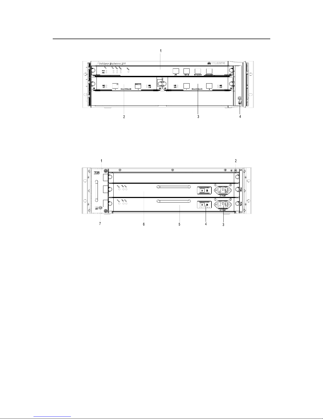
1. RPU Slot0 2. Interface Module Slot1
3. Interface Module Slot2 4. ESD-preventive wrist strap jack
Figure 1-1 Front panel of the Eudemon200 firewall
1. Fan module 2. Grounding screw 3. AC power interface
4. Power switch 5. Power supply unit 2 (PWR2) 6. PWR1
7. ESD-preventive wrist strap port
Figure 1-2 Rear panel of the Eudemon200 firewall
The Eudemon200 firewall has three slots on the front panel, with slot 0 for the RPU and
slots 1 and 2 for interface modules.
Two power supply units (PSU), working in 1+1 backup mode can be horizontally
installed in the Eudemon200 firewall from the rear of the chassis. Both the AC-input
PSU and the DC-input PSU are available, and you may make selection as needed. The
fan module is located at the left rear. The PSU and fan module are both hot swappable.
At the bottom left of the rear panel is an ESD-preventive wrist strap port and at the top
right is a grounding screw.

Installation Manual
Quidway Eudemon200 Firewall Chapter 1 Overview
1-5
1.3 System Parameters
Table 1-1 System parameters of the Eudemon200 firewall
Item Description
Extended slot
2
Fixed interface
2 10/100Mbps Ethernet ports
1 AUX port
1 console port
CPU
PowerPC750 733MHz
Boot ROM 512KB
SDRAM 256MB (may be extended to 512MB)
NVRAM 512KB
Flash memory 32MB
Dimensions (W x D x H)
436.2mm x 420mm x 130.5mm
Weight 20kg
AC: 100V - 240V; 50/60Hz
Input voltage
DC: -48V - -60V
Max. power
150W
Short term
-5°C–50°C
Operating
temperature
Long term
0°C–40°C
Short term
5%–95% (non-condensing)
Relative
humidity
Long term
5%–85% (non-condensing)
Note:
SDRAM (Synchronous Dynamic Random Access Memory) is also known as the memory that stores the
communication data between the system and CPU.
NVRAM (Non-Volatile Random Access Memory) stores the abnormal alarm information
Flash memory functions as the major file storage medium to store application program files, abnormal
information, and configuration files.
BootROM stores the boot program file.
100 - 240V is a standard fluctuating range of AC power supply, but the actual fluctuating range can be 90
to 264 V.
-48 - -60V is a standard fluctuating range of DC power supply, but the actual fluctuating range can be -36
to -72V.

Installation Manual
Quidway Eudemon200 Firewall Chapter 1 Overview
1-6
1.4 Introduction to General Modules
The general modules of the Eudemon200 firewall include RPU, PSU (PWR), FAN, and
interface module, which will be described in the following subsections.
1.4.1 RPU
I. Functions
As the core component of the Eudemon200 firewall, RPU functions primarily to process
protocols, forward low-speed packets, control interfaces, and detect faults. The state
monitoring information, such as the operation states of FAN, PWR, and system can be
shown directly through the LEDs on the RPU, or reported to the Daemon for the
monitoring on the network management system. In addition, the RPU also provides the
hardware reset button RESET.
Following are the functions of the RPU.
1) Processes routing protocols
It achieves the processing of various protocols in Eudemon200 firewall software.
2) Processes the transmission and reception of interface module packet
3) Manages interface status
It implements console interface, AUX interface and fixed Ethernet interface
management, packet transmitted and received processing, and interface working
status indication.
4) Monitors power supply system status
The Eudemon200 has two power modules. RPU can initiatively query and obtain the
abnormal information about power module to implement log and alarm indication.
5) Monitors fan status
Fan is a device that ensures the normal running of the system. Abnormal information
about fan can be obtained based on an interruption alarm signal or initiative query by
CPU. CPU can perform the relevant processing based on the abnormal information
and conduct temperature control and speed adjustment.
6) Monitors system temperature
There is one temperature sensor near the CPU and another near the temperature
control module. When the system is powered on, CPU will pre-set some parameters
such as alarm point for overtemperature and control mode. When measured value on
each temperature sensor is over-high or fan is faulty, the system will send an
interruption signal to CPU. Then CPU generates alarms and controls fan speed,
meanwhile, CPU reads information such as system temperature value, fan status.
Installation Manual
Quidway Eudemon200 Firewall Chapter 1 Overview
1-7
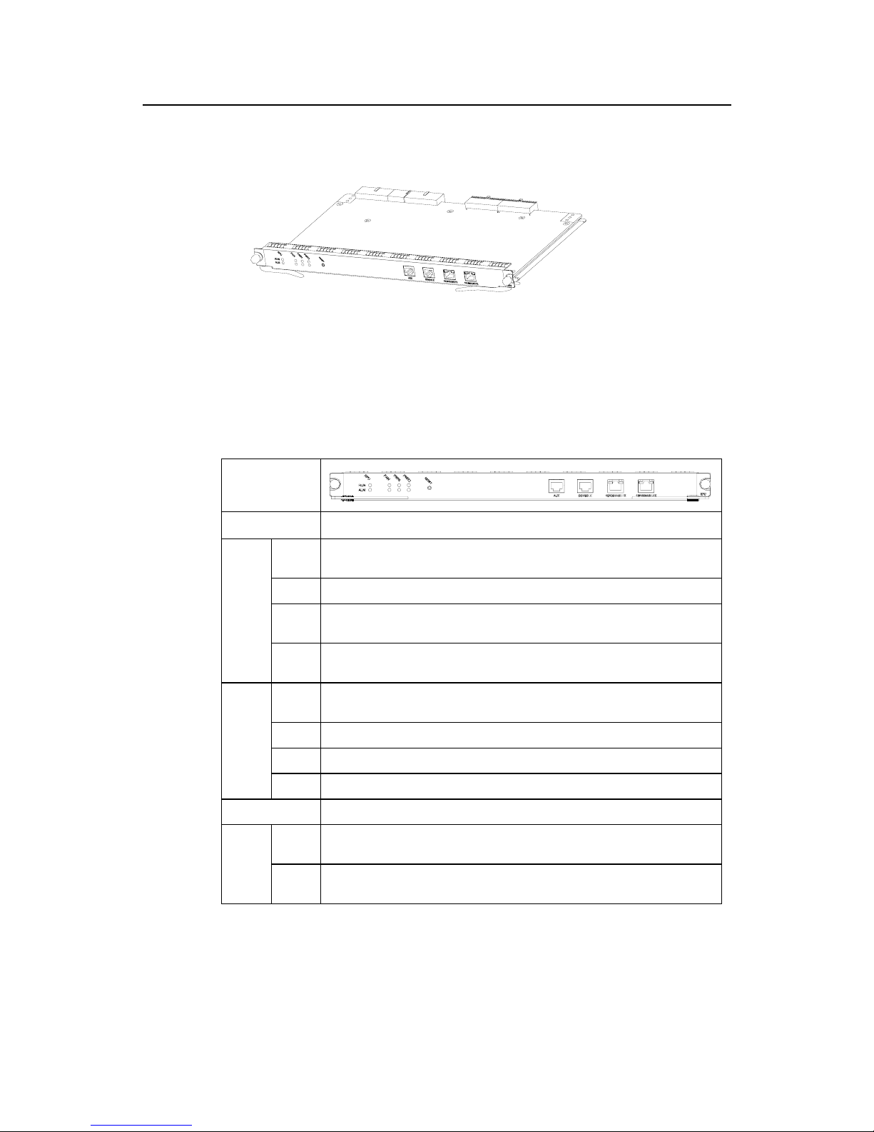
II. Appearance
Figure 1-3 RPU
III. LED and button
Table 1-2 RPU front panel, LED and button description
Front panel
LED and button Description
RPU
System operation LED. Blinking means the CPU is in normal operation, constant ON or
OFF means the CPU has failed.
FAN FAN operation LED. Constant ON means the FAN is operating normally.
PWR1 PWR1 operation LED. Constant ON means PWR1 is operating normally, and constant
OFF means PWR1 is no in place or has failed.
RUN
(green)
PWR2 PWR2 operation LED. Constant ON means PWR2 is operating normally, and constant
OFF means PWR2 is no in place or has failed.
RPU System failure LED. ON means CPU has received an alarm signal for PWR or FAN(due to
overheating, for example).
FAN FAN failure LED. ON means the FAN is no in place or its rotation is obstructed.
PWR1 PWR1 failure LED. ON means PWR1 has failed.
ALM
(red)
PWR2 PWR2 failure LED. ON means PWR2 has failed.
RESET RPU hardware reset button.
LINK
(green)
OFF means the link is not connected and ON means the link is connected.
10/100
Base-T
X LED
ACT
(yellow)
OFF means no data is being transceived on the interface and blinking means data is
being transceived.
IV. Interface
1) Console interface

Installation Manual
Quidway Eudemon200 Firewall Chapter 1 Overview
1-8
Table 1-3 Console interface attributes
Attribute Description
Connector
RJ-45
Interface standard
EIA/TIA-232
Baud rate
9600bps - 115200bps
9600bps by default
Supported service
Connect to the ASCII terminal
Connect to the serial interface of the local PC and run terminal emulation program on the
PC
Command Line Interface (CLI)
2) AUX interface
Table 1-4 AUX interface attributes
Attribute Description
Connector RJ-45
Interface standard EIA/TIA-232
Baud rate 300 ~ 115200bps
Supported service
Modem dialup
Backup
Serve as console port, when the console port fails.
Supported protocol PPP
3) Ethernet interface
The RPU provides two 10/100Base-TX Ethernet ports on its panel (Ethernet 0/0/0 at
left and Ethernet 0/0/1 at right). Their attributes are listed in the following table.

Installation Manual
Quidway Eudemon200 Firewall Chapter 1 Overview
1-9
Table 1-5 Ethernet interface attributes
Attribute Description
Connector
RJ-45
Interface type
MDI
Supported frame
format
Ethernet_II
Ethernet_SNAP
IEEE 802.2
IEEE 802.3
Operating mode
10M/100Mbps auto-sensing
Full duplex/Half-duplex
Supported network
protocol
IP
1.4.2 PWR
I. Functions
The power supply system of the Eudemon200 firewall comprises two PWRs. In normal
situations, the two PWRs (either supplying DC or AC power) function in a redundant
way. The input interruption or failure of a PWR will not affect the operation of another
PWR, and the operating PWR will supply all the power required by the system.
The Eudemon200 firewall provides two types of PWRs, i.e., AC-input PWR and
DC-input PWR, both providing the output power of 350W. AC-input PWR module uses
PSR350-A power supply, and each power module provides an output power of 350W.
The two-way outputs are combined on the backplane. DC-input PWR module uses
PSR350-D power supply, and each power module also provides an output power of
350W. The two-way outputs are also combined on the backplane. Power cable uses
D-type 3PIN -48V feeder cable. PWR has the functions of overcurrent protection and
overvoltage protection.
You can connect the PWR to the backplane by inserting it from the rear of the
Eudemon200 chassis. It is hot swappable and its switchover will not affect the ongoing
system operation.
Installation Manual
Quidway Eudemon200 Firewall Chapter 1 Overview
1-10
Note:
If you want to install a Eudemon200 in a communication equipment room, you should make sure that the
power distribution cabinet can provide the lightning protection box or arrester against the current of 20KA
and above.
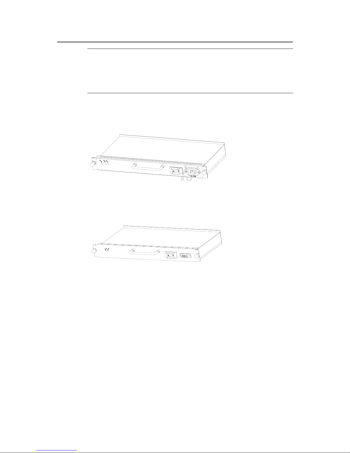
II. Appearance
Figure 1-4 AC PWR
Figure 1-5 DC PWR
Installation Manual
Quidway Eudemon200 Firewall Chapter 1 Overview
1-11
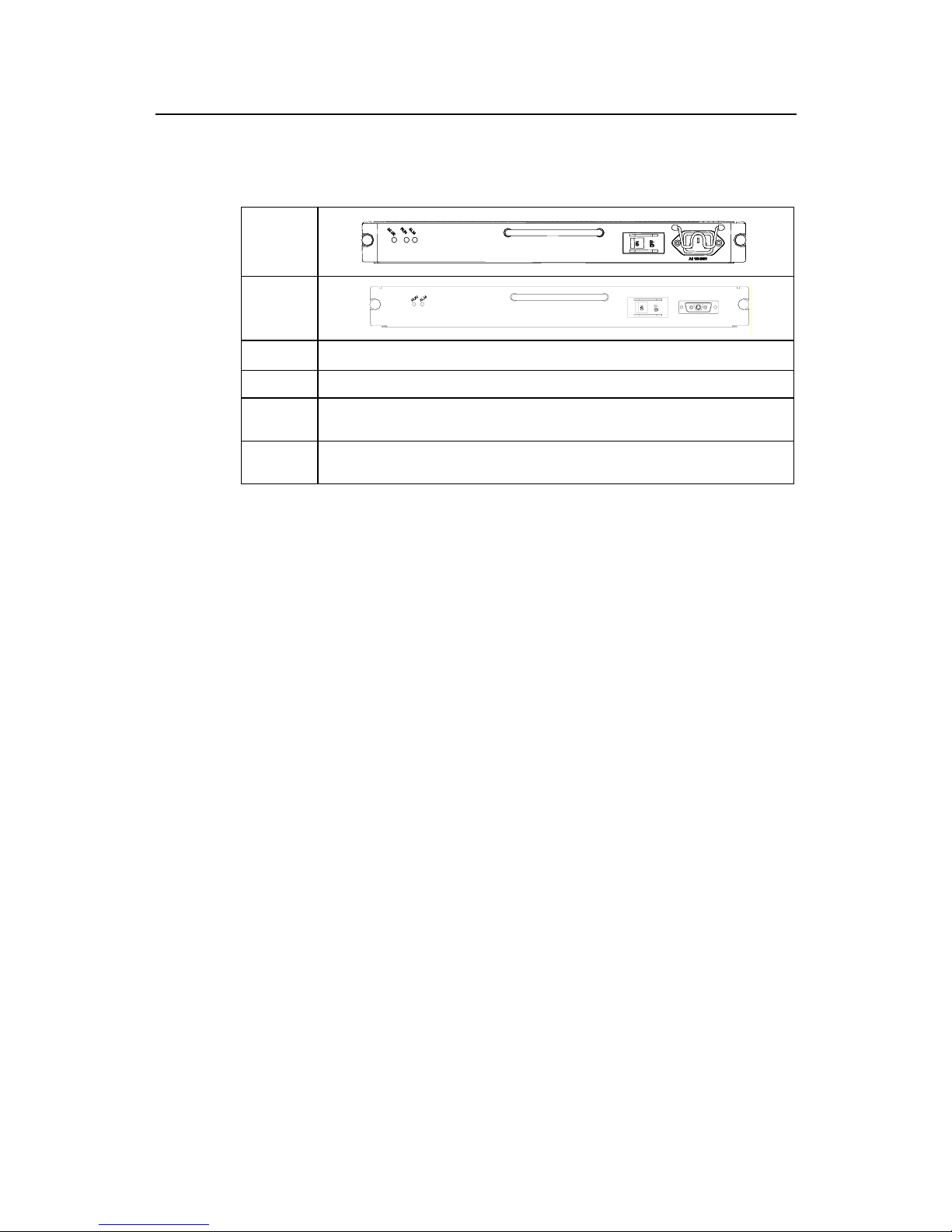
III. Front Panel and LED
Table 1-6 PWR front panel and LED description
AC Front
panel
DC Front
panel
LED Description
ALM (red) PWR failure LED. ON means PWR is not in place or has failed.
RUN (green)
PWR operation LED. Constant ON means PWR is operating normally, and OFF means PWR has
failed.
AC OK (red)
PWR input LED (only for AC PWR). Constant ON means the normal voltage (90- 264V) is
inputting, and OFF means the voltage input is not normal.
1.4.3 FAN
I. Functions
The Eudemon200 firewall is configured with six fans that are separated into three
groups. When all these fans are working normally, the operating temperature of the
system can be maintained in the range of 0 to 55
o
C. As the failure of a fan will not affect
the operation of other fans, the system will still be able to operate in the normal
temperature. The rotating speed of the fans is controlled by the RPU and is in the range
of 50% to 100%. The FAN controller uses two parameters, i.e., low-temperature
threshold and high-temperature threshold to control the rotation speed of the fans, with
the former corresponding to 100% rotating speed and the latter corresponding to 50%
rotating speed. The system will send out rotation stop alarm signals in case any fan fails.
The alarm and state LEDs of FAN are located on the RPU front panel.
II. Appearance
Figure 1-6 shows the FAN appearance.

Installation Manual
Quidway Eudemon200 Firewall Chapter 1 Overview
1-12
Figure 1-6 FAN
1.4.4 Interface Module
z 1-port 10Base-T/100Base-TX Fast Ethernet (FE) interface card (1FE)
z 2-port 10Base-T/100Base-TX FE interface card (2FE)
z 1-port 100Base-FX Ethernet multi-mode fiber interface card (1MFX)
z 1-port 100Base-FX Ethernet single-mode fiber interface card (1SFX)
z 4-port channelized T1 interface card (4T1)
z 4-port channelized E1 interface card (4E1)
z 1-port ATM 155M multi-mode fiber interface card (1ATM-OC3MM)
z 1-port ATM 155M single-mode fiber interface card (1ATM-OC3SM)
z 1-port ATM 155M single-mode long-distance fiber interface card
(1ATM-OC3SML)
For more information about interface modules, refer to “Chapter 8 Interface Module”.

Installation Manual
Quidway Eudemon 200 Firewall Chapter 2 Installation Preparation
2-1
Chapter 2 Installation Preparation
2.1 Site Inspection
To ensure the proper working of the Eudemon200 firewall and prolong their service life,
the installation site should meet the requirements described in the following
subsections.
2.1.1 Equipment Room Environment
To ensure normal operation and prolong the service life of the equipment, the
equipment room must maintain appropriate temperature and humidity and cleanness.
Table 2-1 Requirements for equipment room environment
Item Requirement (index)
Maximum
diameter (µm)
0.05 1 3 5
Particle
Maximum
density
(particles/m
3
)
1.4×10
7
7×10⁵ 2.4×10⁵ 1.3×10⁵
Gas SO2H2SCI2HCl HF NH3 O3 NO
2
Average (mg/m3) 0.3 0.1 0.1 0.1 0.01 1.0 0.05 0.5
Cleanness
Gas
Maximum
(mg/m
3
)
1.0 0.5 0.3 0.5 0.03 3.0 0.1 1.0
Long-term operation Short-term operation
Temperatur
es
0°C-40°C -5°C -50°C
Temperatu
re &
humidity
Humidity 5%-85% 5%-95%
Note: Short-term operation means that the continuous working time does not exceed 72 hours and the accumulated time per
year not exceed 15 days. The temperature and humidity value is measured in the environment that no protecting boards are
installed in front of or behind the rack, and it is taken 1.5 meters above the floor and 0.4 meters in front of the rack.
2.1.2 ESD Protection
Despite careful considerations have been taken in preventing ESD in the design of the
equipment, excessive static electricity may bring enormous damage to the card circuits
and even the entire equipment.

Installation Manual
Quidway Eudemon 200 Firewall Chapter 2 Installation Preparation
2-2
On the communication network connected to the equipment, the static electricity is
primarily introduced from the outside electrical fields, such as the outdoor high-voltage
power cable and lightning, and from the inside system, such as indoor environment,
floor material and the equipment frame. To avoid the damage caused by the static
electricity, you should ensure that:
z The equipment is well connected to earth.
z The equipment room is dust-proof.
z Keep adequate temperature and humidity.
z Wear the ESD-preventive wrist strap and clothes when contacting the circuit
board.
z Place the removed circuit board upward on the ESD-preventive workbench, or into
a static shielded bag.
z Hold the circuit board by the outer edge when observing or moving it, so as to
avoid direct contact with the elements on it.
2.1.3 Electromagnetic Environment
All interference sources, no matter from the outside of the equipment or the application
system, or from the inside, will influence the equipment negatively in the conduction
patterns of capacitance coupling, inductance coupling, electromagnetic wave radiation,
and common impedance (including grounding system) coupling. To prevent the
interference, you should:
z Take effective measures against electricity network interference with the power
supply system.
z Do not use the working ground of the equipment together with the grounding or
lightning protection grounding device of the power equipment. Separate them as
far as possible.
z Keep the equipment far away from strong power wireless launchers, radar
launchers and high frequency and high-current equipment.
z Use electromagnetic shielding if necessary.
2.1.4 Lightning Protection
Despite careful considerations have been taken in lightning protection in the design of
the equipments and measures have been adopted, excessive-degree of lightning may
still damage the equipments. To achieve the best lightning protection effect, you are
recommended to:
z Keep the grounding wire of the PGND of the chassis in good contact with the earth
ground.
z Keep the grounding terminal of the AC power socket in good contact with the earth
ground.

Installation Manual
Quidway Eudemon 200 Firewall Chapter 2 Installation Preparation
2-3
z Add a lightning arrester for power supply onto the front end of the power input in
order to protect the power supply from lightning strikes in a more effective way.
z Add a special lightning protection facility at the input end of the signal cables in
order to protect the signal cables led to the outdoors, such as ISDN cable, and
E1/T1 cable, from lightning strikes in a more effective way.
2.1.5 Workbench
Following are the rules that you should observe when installing the equipment:
z Leave enough clearance at the air intake vents and air exhausting vents to ensure
adequate ventilation of the equipment chassis.
z Make sure that the workbench has a good ventilation system.
z Make sure that the workbench is stable enough and can support the weight of the
equipment and the installation accessories.
z Make sure that the workbench has been well-grounded.
2.2 Safety Recommendations
When reading this manual, you should pay adequate attention to the following symbol
and the contents beneath it.
Caution appears throughout this manual in procedures that, if performed
incorrectly, might harm you or damage the Eudemon200 firewall equipment.
When installing or working on a equipment, you are recommended to:
z Keep the equipment far away from the heat sources and water/liquid.
z Make sure that the equipment has been correctly grounded.
z Wear ESD-preventive wrist strap in the installation and maintenance, make sure
that the strap has good skin-contact.
z Do not hot swap the RPU of the equipment.
z Do not plug/unplug cables if there is electricity.
z Connect the cables to the ports appropriate to them. Above all, do not insert the
ISDN cable into a serial port.
z Use laser cautions. Do not directly stare into the radiation aperture of the laser or
the fiber connector connected to it.
z Adopt Uninterrupted Power Supply (UPS).
2.3 Checking Eudemon200 and Accessories
After having confirmed that the installation conditions comply with the requirements,
please open the packing cases of the equipment and check that the equipment and the
 Loading...