

Huawei Quidway AR 46, Quidway AR 46-20, Quidway AR 46-40, Quidway AR 46-80 Installation Manual
Page 1

Chapter 1 Router Overview 1-1.............................................................................
1.1 Introduction 1-1.............................................................................................
1.2 Router Model and Structure 1-3...................................................................
1.2.1 AR 46-20 1-3........................................................................................
1.2.2 AR 46-40 1-4........................................................................................
1.2.3 AR 46-80 1-5........................................................................................
1.3 System description 1-7.................................................................................
1.4 Introduction to General Modules 1-7............................................................
1.4.1 RPU 1-8...............................................................................................
1.4.2 PWR 1-10...............................................................................................
1.4.3 FAN 1-12................................................................................................
1.4.4 FIC 1-13.................................................................................................
Chapter 2 Installation Preparation 2-1.................................................................
2.1 General Site Requirements 2-1....................................................................
2.1.1 Temperature/Humidity Requirements 2-1............................................
2.1.2 Cleanliness Requirements 2-1.............................................................
2.1.3 ESD Preventive Requirements 2-2......................................................
2.1.4 Electromagnetic Environment Requirements 2-3.................................
2.1.5 Lightning Protection Requirements 2-3................................................
2.1.6 Check Workbench 2-3..........................................................................
2.2 Safety Recommendations 2-4......................................................................
2.3 Check Router and Accessories 2-4..............................................................
2.4 Installation Tools and Meters and Equipment 2-5........................................
Chapter 3 Router Installation 3-1..........................................................................
3.1 Router Installation Flow 3-1..........................................................................
3.2 Install Cabinet 3-2.........................................................................................
3.3 Mount Router to a Specified Place 3-2.........................................................
3.3.1 Rack Mount Router 3-2........................................................................
3.3.2 Bench-Mount Router 3-3......................................................................
3.4 Install the General Modules 3-3....................................................................
3.5 Connect the PGND 3-3.................................................................................
3.6 Connect Power Cord 3-4..............................................................................
3.6.1 Connect AC Power Cord 3-5................................................................
3.6.2 Connect DC Power Cord 3-5...............................................................
3.7 Connect the Console Terminal 3-7...............................................................
3.8 Connect Router to LAN 3-8..........................................................................
3.9 Connect Router to WAN 3-9.........................................................................
3.9.1 Connect the AUX Port to Modem 3-9...................................................
3.10 Verify Installation 3-10..................................................................................
Page 2

Chapter 4 Booting and Configuration 4-1............................................................
4.1 Boot a Router 4-1.........................................................................................
4.1.1 Establish Configuration Environment 4-1.............................................
4.1.2 Power on the Router 4-4......................................................................
4.1.3 Startup Process 4-5.............................................................................
4.2 Router Configuration Fundamentals 4-8......................................................
4.2.1 Basic Configuration Procedure 4-8......................................................
4.2.2 Command Line Interface 4-9................................................................
4.2.3 Slot Arrangement and Interface Numbering Rules 4-9........................
Chapter 5 Software Maintenance 5-1...................................................................
5.1 Overview 5-1................................................................................................
5.2 Boot Menu 5-1..............................................................................................
5.2.1 Boot Sub-menu 5-2..............................................................................
5.2.2 Boot Main Menu 5-3.............................................................................
5.3 Upgrading Program Files Using Xmodem Protocol 5-8................................
5.3.1 Upgrading Boot ROM Program 5-8......................................................
5.3.2 Upgrading application program 5-10......................................................
5.4 Upgrading Application Program via Ethernet Port 5-11..................................
5.5 Dealing with Missing of Router Password 5-13..............................................
Chapter 6 Hardware Maintenance 6-1..................................................................
6.1 Prepare Tools 6-1.........................................................................................
6.2 Power Module Removal and Installation 6-1................................................
6.2.1 Remove a Power Module 6-1...............................................................
6.2.2 Install a Power Module 6-2...................................................................
6.3 Fan Removal and Installation 6-2.................................................................
6.3.1 Remove a Fan 6-2...............................................................................
6.3.2 Install a Fan 6-3...................................................................................
6.4 RPU Removal and Installation 6-3...............................................................
6.4.1 Remove an RPU 6-3............................................................................
6.4.2 Install an RPU 6-4................................................................................
6.5 Replace SDRAM 6-4....................................................................................
Chapter 7 Troubleshooting 7-1.............................................................................
7.1 Troubleshooting of the Power System 7-1...................................................
7.2 Troubleshooting of the Configuration System 7-1........................................
7.3 Troubleshooting of Application Software Upgrade 7-2.................................
Chapter 8 FIC 8-1...................................................................................................
8.1 FIC Categories 8-1.......................................................................................
8.2 Remove and Install FIC 8-3..........................................................................
Page 3

8.3 Troubleshooting 8-4......................................................................................
8.4 RT-FIC-1FE/RT-FIC-2FE 8-4.......................................................................
8.4.1 Introduction 8-4....................................................................................
8.4.2 Interface Attributes 8-4.........................................................................
8.4.3 Panel and Interface LED 8-5................................................................
8.4.4 Interface Cable 8-5...............................................................................
8.4.5 Connect Interface Cable 8-6................................................................
8.5 RT-FIC-1MFX/RT-FIC-1SFX 8-7..................................................................
8.5.1 Introduction 8-7....................................................................................
8.5.2 Interface Attributes 8-7.........................................................................
8.5.3 Panel and Interface LED 8-8................................................................
8.5.4 Interface Optical Fiber 8-8....................................................................
8.5.5 Connect Interface Optical Fiber 8-9.....................................................
8.6 RT-FIC-1GE 8-10...........................................................................................
8.6.1 Introduction 8-10....................................................................................
8.6.2 Interface Attributes 8-10.........................................................................
8.6.3 Panel and Interface LEDs 8-11..............................................................
8.6.4 Interface Cable 8-11...............................................................................
8.6.5 Connecting Interface Cable 8-12...........................................................
8.7 RT-FIC-2SAE/RT-FIC-4SAE/RT-FIC-8SAE 8-12...........................................
8.7.1 Introduction 8-12....................................................................................
8.7.2 Interface Attributes 8-13.........................................................................
8.7.3 Panel and Interface LEDs 8-14..............................................................
8.7.4 Interface Cable 8-15...............................................................................
8.7.5 Connecting the Interface Cable 8-18.....................................................
8.8 RT-FIC-8ASE/ RT-FIC-16ASE 8-19...............................................................
8.8.1 Introduction 8-19....................................................................................
8.8.2 Interface Attributes 8-19.........................................................................
8.8.3 Panel and Interface LEDs 8-20..............................................................
8.8.4 Interface Cable 8-20...............................................................................
8.8.5 Connecting the Interface Cable 8-21.....................................................
8.9 RT-FIC-6AM/RT-FIC-12AM 8-22....................................................................
8.9.1 Introduction 8-22....................................................................................
8.9.2 Interface Attributes 8-22.........................................................................
8.9.3 Panel and Interface LED 8-22................................................................
8.9.4 Interface Cable 8-23...............................................................................
8.9.5 Connect Interface Cable 8-23................................................................
8.10 RT-FIC-1E1/RT-FIC-2E1/RT-FIC-4E1 and
RT-FIC-1E1-F/RT-FIC-2E1-F/RT-FIC-4E1-F 8-24...............................................
8.10.1 Introduction 8-24..................................................................................
8.10.2 Interface Attributes 8-24.......................................................................
Page 4

8.10.3 Panel and Interface LED 8-25..............................................................
8.10.4 Interface Cable 8-27.............................................................................
8.10.5 Internal DIP Switch 8-30......................................................................
8.10.6 Connect Interface Cable 8-31..............................................................
8.11 RT-FIC-1T1/RT-FIC-2T1/RT-FIC-4T1 and
RT-FIC-1T1-F/RT-FIC-2T1-F/RT-FIC-4T1-F 8-34................................................
8.11.1 Introduction 8-34..................................................................................
8.11.2 Interface Attributes 8-34.......................................................................
8.11.3 Panel and Interface LED 8-34..............................................................
8.11.4 Interface Cable 8-36.............................................................................
8.11.5 Connect Interface Cable 8-36..............................................................
8.12 RT-FIC-1CE3 8-37.......................................................................................
8.12.1 Introduction 8-37..................................................................................
8.12.2 Interface Attributes 8-38.......................................................................
8.12.3 Panel and Interface LED 8-38..............................................................
8.12.4 Interface Cable 8-39.............................................................................
8.12.5 Connect Interface Cable 8-39..............................................................
8.13 RT-FIC-1CT3 8-40........................................................................................
8.13.1 Introduction 8-40..................................................................................
8.13.2 Interface Attributes 8-40.......................................................................
8.13.3 Panel and Interface LED 8-40..............................................................
8.13.4 Interface Cable 8-41.............................................................................
8.14 RT-FIC-4BS 8-41..........................................................................................
8.14.1 Introduction 8-41..................................................................................
8.14.2 Interface Attributes 8-41.......................................................................
8.14.3 Internal DIP Switch 8-42......................................................................
8.14.4 Panel and Interface LED 8-43..............................................................
8.14.5 Interface Cable 8-43.............................................................................
8.14.6 Connect Interface Cable 8-44..............................................................
8.15 RT-FIC-1AE3 8-44........................................................................................
8.15.1 Introduction 8-44..................................................................................
8.15.2 Interface Attributes 8-45.......................................................................
8.15.3 Panel and Interface LEDs 8-45............................................................
8.15.4 Interface Cable 8-46.............................................................................
8.15.5 Connecting Interface Cable 8-46.........................................................
8.16 RT-FIC-1AT3 8-47........................................................................................
8.16.1 Introduction 8-47..................................................................................
8.16.2 Interface Attributes 8-47.......................................................................
8.16.3 Panel and Interface LEDs 8-48............................................................
8.16.4 Interface Cable 8-48.............................................................................
8.16.5 Connecting Interface Cable 8-48.........................................................
Page 5

8.17 RT-FIC-1ATM-25M 8-49...............................................................................
8.17.1 Introduction 8-49..................................................................................
8.17.2 Interface Attributes 8-50.......................................................................
8.17.3 Panel and Interface LEDs 8-50............................................................
8.17.4 Interface Cable 8-50.............................................................................
8.17.5 Connecting Interface Cable 8-51.........................................................
8.18 RT-FIC-1ATM-OC3MM /RT-FIC-1ATM-OC3SM/RT-FIC-1A
TM-OC3SML 8-52................................................................................................
8.18.1 Introduction 8-52..................................................................................
8.18.2 Interface Attributes 8-53.......................................................................
8.18.3 Panel and Interface LED 8-53..............................................................
8.18.4 Interface Optical Fiber 8-54..................................................................
8.19 RT-FIC-1ADSL/RT-FIC-2ADSL 8-55............................................................
8.19.1 Introduction 8-55..................................................................................
8.19.2 Interface Attributes 8-56.......................................................................
8.19.3 Panel and Interface LED 8-56..............................................................
8.19.4 Interface Cable 8-57.............................................................................
8.19.5 Connect Interface Cable 8-57..............................................................
8.20 RT-FIC-1ADSL-I/2ADSL-I 8-58....................................................................
8.20.1 Introduction 8-58..................................................................................
8.20.2 Interface Attributes 8-58.......................................................................
8.20.3 Panel and Interface LEDs 8-59............................................................
8.20.4 Interface Cable 8-59.............................................................................
8.20.5 Connecting Interface Cable 8-59.........................................................
8.21 RT-FIC-1G.SHDSL/2G.SHDSL/4G.SHDSL 8-60.........................................
8.21.1 Introduction 8-60..................................................................................
8.21.2 Interface Attributes 8-60.......................................................................
8.21.3 Panel and Interface LEDs 8-61............................................................
8.21.4 Interface Cable 8-61.............................................................................
8.21.5 Connecting Interface Cable 8-61.........................................................
8.22 RT-FIC-2FXS/RT-FIC-2FXO and RT-FIC-4FXS/RT-FIC-4FXO 8-62...........
8.22.1 Introduction 8-62..................................................................................
8.22.2 Interface Attributes 8-62.......................................................................
8.22.3 Panel and Interface LED 8-63..............................................................
8.22.4 Interface Cable 8-63.............................................................................
8.22.5 Connect Interface Cable 8-64..............................................................
8.23 RT-FIC-E1VI 8-64.........................................................................................
8.23.1 Introduction 8-64..................................................................................
8.23.2 Interface Attributes 8-65.......................................................................
8.23.3 Panel and Interface LED 8-65..............................................................
8.23.4 Interface Cable 8-66.............................................................................
Page 6

8.23.5 Connect Interface Cable 8-66..............................................................
8.24 RT-FIC-T1VI 8-68.........................................................................................
8.24.1 Introduction 8-68..................................................................................
8.24.2 Interface Attributes 8-68.......................................................................
8.24.3 Panel and Interface LED 8-68..............................................................
8.24.4 Interface Cable 8-69.............................................................................
8.24.5 Connect Interface Cable 8-69..............................................................
Appendix A Installation of B68 Cabinet A-1.........................................................
A.1 Installation Requirement and Brief Procedure A-1.......................................
A.1.1 Spatial Planning Requirement A-1.......................................................
A.1.2 Brief Installation Procedure A-2...........................................................
A.2 Cabinet Installation on the Cement Floor A-3...............................................
A.2.1 The Composition of Integrated Pressure Plate A-3..............................
A.2.2 Installation Flow A-4.............................................................................
A.2.3 Cabinet Positioning A-5........................................................................
A.2.4 Cabinet Leveling A-8............................................................................
A.2.5 Combined cabinet connection A-9.......................................................
A.2.6 Cabinet fixing A-11.................................................................................
A.2.7 Insulation test A-13................................................................................
A.3 Cabinet Installation on Antistatic Floor A-14...................................................
A.3.1 Brief Introduction to Rack A-15..............................................................
A.3.2 Brief Introduction to Slide Rail A-17.......................................................
A.3.3 Installation Flow A-17.............................................................................
A.3.4 Rack positioning A-18............................................................................
A.3.5 Rack installation A-21............................................................................
A.3.6 Install slide rail A-23...............................................................................
A.3.7 Install Supporting Accessories of Antistatic Floor A-26..........................
A.3.8 Cabinet Leveling A-27............................................................................
A.3.9 Combined cabinet connection A-29.......................................................
A.3.10 Fixing the Cabinet A-31........................................................................
A.3.11 Insulation test A-33..............................................................................
A.3.12 Restoring the Floor A-34......................................................................
Page 7

HUAWEI
Quidway AR 46 Series Routers
Installation Manual
Page 8

Quidway AR 46 Series Routers
Installation Manual
Manual Version
T2-080466-20040318-C-1.01
BOM
31040866
Huawei Technologies Co., Ltd. provides customers with comprehensive technical support
and service. If you purchase the products from the sales agent of Huawei Technologies Co.,
Ltd., please contact our sales agent. If you purchase the products from Huawei
Technologies Co., Ltd. directly, Please feel free to contact our local office, customer care
center or company headquarters.
Huawei Technologies Co., Ltd.
Ad dress: Administration Building, Huawei Technologies Co., Ltd.,
Bantian, Longgang District, Shenzhen, P. R. China
Postal Code: 518129
Website: http://www.huawei.com
Page 9

Copyright © 2004 Huawei Technologies Co., Ltd.
All Rights Reserved
No part of this manual may be reproduced or transmitted in any form or by any
means without prior written consent of Huawei Technologies Co., Ltd.
Trademarks
, HUAWEI, C&C08, EAST8000, HONET, , ViewPoint, INtess, ETS, DMC,
TELLIN, InfoLink, Netkey, Quidway, SYNLOCK, Radium,
M900/M1800,
TELESIGHT, Quidview, Musa, Airbridge, Tellwin, Inmedia, VRP, DOPRA, iTELLIN,
HUAWEI OptiX, C&C08
iNET, NETENGINE, OptiX, iSite, U-SYS, iMUSE, OpenEye,
Lansway, SmartAX, infoX, TopEng are trademarks of Huawei Technologies Co.,
Ltd.
All other trademarks mentioned in this manual are the property of their respective
holders.
Notice
The information in this manual is subject to change without notice. Every effort has
been made in the preparation of this manual to ensure accuracy of the contents, but
all statements, information, and recommendations in this manual do not constitute
the warranty of any kind, express or implied.
Page 10

About This Manual
Version
The product corresponding to the manual is Quidway AR 46-20/46-40/46-80 Router.
Related Manuals
The following manuals provide more information about the Quidway AR 46 Series
Routers.
Manual Content
Low-End-and-Mid-Range Series Routers
Cable Manual
The manual introduces the connection of pins of all the cables
related to the low-end and middle-range routers.
VRP3 Operation Manual
The manual is a guide for the user to use VRP3.3 to perform the
operations correctly. It is organized into the parts of getting started,
system management, interface, link layer protocol, network
protocol, routing protocol, multicast protocol security, VPN,
reliability, QoS, MPLS and dial-up, as well as abbreviations used
in the manual.
VRP3 Command Manual
The manual gives the user a detailed description of the operating
commands in VRP3.3. It is organized into the parts of getting
started, system management, interface, link layer protocol,
network protocol, routing protocol, multicast protocol, security,
VPN, reliability, QoS, MPLS and dial-up, as well as a command
index.
Organization of the Manual
Quidway AR 46 Series Routers Installation Manual is organized as follows:
Chapter 1 Router Overview This chapter briefly introduces the models of Quidway
AR 46 Series Routers and the supported modules, as well as the features of the
routers.
Chapter 2 Installation Preparation This chapter describes the requirements on
installation site, the safety recommendations before and during installation, and the
required tools.
Chapter 3 Router Installation This chapter covers the procedure for installing
Quidway AR 46 Series Routers, power cord connection, AUX cable connection,
Console cable connection and Ethernet cable connection.
Page 11

Chapter 4 Booting and Configuration This chapter helps you get familiar with the
basic knowledge of how to boot and configure Quidway AR 46 Series Routers,
including startup of router, power-on, and initialization of system files, etc.
Chapter 5 Software Maintenance This chapter introduces how to maintain Boot
ROM menu and software of Quidway AR 46 Series Routers.
Chapter 6 Hardware Maintenance This chapter introduces how to replace the power
module, fan, main control board and SDRAM of Quidway AR 46 Series Routers.
Chapter 7 Troubleshooting This chapter describes some problems that may arise
and how to solve them.
Chapter 8 FIC This chapter introduces Flexible Interface Card (FIC) of Quidway AR 46
Series Routers from the aspects of appearance, panel and LED, installation of FICs,
and connection of interface cable, etc.
Chapter 9 Appendix This appendix introduces the installation of B68 cabinet.
Intended Readers
The manual is intended for the following readers:
z Network engineers
z Network administrators
z Customers who are familiar with network fundamentals
Conventions
This manual uses the following conventions:
I. General conventions
Convention Description
Arial
Normal paragraphs are in Arial.
Arial Narrow Warnings, Cautions, Notes and Tips are in Arial Narrow.
Boldface Headings are in Boldface.
Courier New
Terminal Display is in Courier New.
Page 12

II. GUI conventions
Convention Description
< > Button names are inside angle brackets. For example, click <OK> button.
[ ]
Window names, menu items, data table and field names are inside square
brackets. For example, pop up the [New User] window.
/
Multi-level menus are separated by forward slashes. For example,
[File/Create/Folder].
III. Keyboard operation
Format Description
<Key>
Press the key with the key name inside angle brackets. For example, <Enter>,
<Tab>, <Backspace>, or <A>.
<Key1+Key2>
Press the keys concurrently. For example, <Ctrl+Alt+A> means the three keys
should be pressed concurrently.
<Key1, Key2>
Press the keys in turn. For example, <Alt, A> means the two keys should be
pressed in turn.
IV. Symbols
Eye-catching symbols are also used in the manual to highlight the points worthy of
special attention during the operation. They are defined as follows:
Caution: Means reader be extremely careful during the operation.
Note: Means a complementary description.
Environmental Protection
This product has been designed to comply with the requirements on environmental
protection. For the proper storage, use and disposal of this product, national laws and
regulations must be observed.
Page 13

Installation Manual
Quidway AR 46 Series Routers Table of Contents
i
Table of Contents
Chapter 1 Router Overview .......................................................................................................... 1-1
1.1 Introduction ........................................................................................................................ 1-1
1.2 Router Model and Structure............................................................................................... 1-3
1.2.1 AR 46-20 ................................................................................................................. 1-3
1.2.2 AR 46-40 ................................................................................................................. 1-4
1.2.3 AR 46-80 ................................................................................................................. 1-5
1.3 System description ............................................................................................................ 1-7
1.4 Introduction to General Modules........................................................................................ 1-7
1.4.1 RPU......................................................................................................................... 1-8
1.4.2 PWR ...................................................................................................................... 1-10
1.4.3 FAN .......................................................................................................................1-12
1.4.4 FIC......................................................................................................................... 1-13
Chapter 2 Installation Preparation............................................................................................... 2-1
2.1 General Site Requirements ............................................................................................... 2-1
2.1.1 Temperature/Humidity Requirements ..................................................................... 2-1
2.1.2 Cleanliness Requirements ...................................................................................... 2-1
2.1.3 ESD Preventive Requirements ............................................................................... 2-2
2.1.4 Electromagnetic Environment Requirements.......................................................... 2-3
2.1.5 Lightning Protection Requirements......................................................................... 2-3
2.1.6 Check Workbench................................................................................................... 2-3
2.2 Safety Recommendations.................................................................................................. 2-4
2.3 Check Router and Accessories ......................................................................................... 2-4
2.4 Installation Tools and Meters and Equipment ................................................................... 2-5
Chapter 3 Router Installation ....................................................................................................... 3-1
3.1 Router Installation Flow ..................................................................................................... 3-1
3.2 Install Cabinet .................................................................................................................... 3-2
3.3 Mount Router to a Specified Place .................................................................................... 3-2
3.3.1 Rack Mount Router ................................................................................................. 3-2
3.3.2 Bench-Mount Router ............................................................................................... 3-3
3.4 Install the General Modules ............................................................................................... 3-3
3.5 Connect the PGND ............................................................................................................3-3
3.6 Connect Power Cord ......................................................................................................... 3-4
3.6.1 Connect AC Power Cord......................................................................................... 3-5
3.6.2 Connect DC Power Cord......................................................................................... 3-5
3.7 Connect the Console Terminal .......................................................................................... 3-7
3.8 Connect Router to LAN...................................................................................................... 3-8
3.9 Connect Router to WAN .................................................................................................... 3-9
Page 14

Installation Manual
Quidway AR 46 Series Routers Table of Contents
ii
3.9.1 Connect the AUX Port to Modem............................................................................ 3-9
3.10 Verify Installation ........................................................................................................... 3-10
Chapter 4 Booting and Configuration ......................................................................................... 4-1
4.1 Boot a Router..................................................................................................................... 4-1
4.1.1 Establish Configuration Environment...................................................................... 4-1
4.1.2 Power on the Router ............................................................................................... 4-4
4.1.3 Startup Process....................................................................................................... 4-5
4.2 Router Configuration Fundamentals.................................................................................. 4-8
4.2.1 Basic Configuration Procedure ............................................................................... 4-8
4.2.2 Command Line Interface......................................................................................... 4-9
4.2.3 Slot Arrangement and Interface Numbering Rules ................................................. 4-9
Chapter 5 Software Maintenance................................................................................................. 5-1
5.1 Overview ............................................................................................................................ 5-1
5.2 Boot Menu.......................................................................................................................... 5-1
5.2.1 Boot Sub-menu ....................................................................................................... 5-2
5.2.2 Boot Main Menu ...................................................................................................... 5-3
5.3 Upgrading Program Files Using Xmodem Protocol........................................................... 5-8
5.3.1 Upgrading Boot ROM Program ............................................................................... 5-8
5.3.2 Upgrading application program............................................................................. 5-10
5.4 Upgrading Application Program via Ethernet Port........................................................... 5-11
5.5 Dealing with Missing of Router Password ....................................................................... 5-13
Chapter 6 Hardware Maintenance................................................................................................ 6-1
6.1 Prepare Tools .................................................................................................................... 6-1
6.2 Power Module Removal and Installation ........................................................................... 6-1
6.2.1 Remove a Power Module........................................................................................ 6-1
6.2.2 Install a Power Module............................................................................................ 6-2
6.3 Fan Removal and Installation ............................................................................................ 6-2
6.3.1 Remove a Fan......................................................................................................... 6-2
6.3.2 Install a Fan.............................................................................................................6-3
6.4 RPU Removal and Installation........................................................................................... 6-3
6.4.1 Remove an RPU ..................................................................................................... 6-3
6.4.2 Install an RPU ......................................................................................................... 6-4
6.5 Replace SDRAM................................................................................................................ 6-4
Chapter 7 Troubleshooting .......................................................................................................... 7-1
7.1 Troubleshooting of the Power System............................................................................... 7-1
7.2 Troubleshooting of the Configuration System ................................................................... 7-1
7.3 Troubleshooting of Application Software Upgrade ............................................................ 7-2
Chapter 8 FIC ................................................................................................................................. 8-1
8.1 FIC Categories................................................................................................................... 8-1
8.2 Remove and Install FIC ..................................................................................................... 8-3
8.3 Troubleshooting ................................................................................................................. 8-4
Page 15

Installation Manual
Quidway AR 46 Series Routers Table of Contents
iii
8.4 RT-FIC-1FE/RT-FIC-2FE................................................................................................... 8-4
8.4.1 Introduction..............................................................................................................8-4
8.4.2 Interface Attributes .................................................................................................. 8-4
8.4.3 Panel and Interface LED ......................................................................................... 8-5
8.4.4 Interface Cable........................................................................................................ 8-5
8.4.5 Connect Interface Cable ......................................................................................... 8-6
8.5 RT-FIC-1MFX/RT-FIC-1SFX ............................................................................................. 8-7
8.5.1 Introduction..............................................................................................................8-7
8.5.2 Interface Attributes .................................................................................................. 8-7
8.5.3 Panel and Interface LED ......................................................................................... 8-8
8.5.4 Interface Optical Fiber............................................................................................. 8-8
8.5.5 Connect Interface Optical Fiber .............................................................................. 8-9
8.6 RT-FIC-1GE..................................................................................................................... 8-10
8.6.1 Introduction............................................................................................................ 8-10
8.6.2 Interface Attributes ................................................................................................ 8-10
8.6.3 Panel and Interface LEDs ..................................................................................... 8-11
8.6.4 Interface Cable...................................................................................................... 8-11
8.6.5 Connecting Interface Cable................................................................................... 8-12
8.7 RT-FIC-2SAE/ RT-FIC-4SAE/ RT-FIC-8SAE .................................................................. 8-12
8.7.1 Introduction............................................................................................................ 8-12
8.7.2 Interface Attributes ................................................................................................ 8-13
8.7.3 Panel and Interface LEDs ..................................................................................... 8-14
8.7.4 Interface Cable...................................................................................................... 8-15
8.7.5 Connecting the Interface Cable............................................................................. 8-18
8.8 RT-FIC-8ASE/ RT-FIC-16ASE ........................................................................................ 8-19
8.8.1 Introduction............................................................................................................ 8-19
8.8.2 Interface Attributes ................................................................................................ 8-19
8.8.3 Panel and Interface LEDs ..................................................................................... 8-20
8.8.4 Interface Cable...................................................................................................... 8-20
8.8.5 Connecting the Interface Cable............................................................................. 8-21
8.9 RT-FIC-6AM/RT-FIC-12AM ............................................................................................. 8-22
8.9.1 Introduction............................................................................................................ 8-22
8.9.2 Interface Attributes ................................................................................................ 8-22
8.9.3 Panel and Interface LED ....................................................................................... 8-22
8.9.4 Interface Cable...................................................................................................... 8-23
8.9.5 Connect Interface Cable ....................................................................................... 8-23
8.10 RT-FIC-1E1/RT-FIC-2E1/RT-FIC-4E1 and RT-FIC-1E1-F/RT-FIC-2E1-F/RT-FIC-4E1-F8-24
8.10.1 Introduction.......................................................................................................... 8-24
8.10.2 Interface Attributes .............................................................................................. 8-24
8.10.3 Panel and Interface LED ..................................................................................... 8-25
8.10.4 Interface Cable.................................................................................................... 8-27
8.10.5 Internal DIP Switch.............................................................................................. 8-30
Page 16

Installation Manual
Quidway AR 46 Series Routers Table of Contents
iv
8.10.6 Connect Interface Cable ..................................................................................... 8-31
8.11 RT-FIC-1T1/RT-FIC-2T1/RT-FIC-4T1 and RT-FIC-1T1-F/RT-FIC-2T1-F/RT-FIC-4T1-F8-34
8.11.1 Introduction.......................................................................................................... 8-34
8.11.2 Interface Attributes .............................................................................................. 8-34
8.11.3 Panel and Interface LED ..................................................................................... 8-34
8.11.4 Interface Cable.................................................................................................... 8-36
8.11.5 Connect Interface Cable ..................................................................................... 8-36
8.12 RT-FIC-1CE3................................................................................................................. 8-37
8.12.1 Introduction.......................................................................................................... 8-37
8.12.2 Interface Attributes .............................................................................................. 8-38
8.12.3 Panel and Interface LED ..................................................................................... 8-38
8.12.4 Interface Cable.................................................................................................... 8-39
8.12.5 Connect Interface Cable ..................................................................................... 8-39
8.13 RT-FIC-1CT3 ................................................................................................................. 8-40
8.13.1 Introduction.......................................................................................................... 8-40
8.13.2 Interface Attributes .............................................................................................. 8-40
8.13.3 Panel and Interface LED ..................................................................................... 8-40
8.13.4 Interface Cable.................................................................................................... 8-41
8.14 RT-FIC-4BS ................................................................................................................... 8-41
8.14.1 Introduction.......................................................................................................... 8-41
8.14.2 Interface Attributes .............................................................................................. 8-41
8.14.3 Internal DIP Switch.............................................................................................. 8-42
8.14.4 Panel and Interface LED ..................................................................................... 8-43
8.14.5 Interface Cable.................................................................................................... 8-43
8.14.6 Connect Interface Cable ..................................................................................... 8-44
8.15 RT-FIC-1AE3 ................................................................................................................. 8-44
8.15.1 Introduction.......................................................................................................... 8-44
8.15.2 Interface Attributes .............................................................................................. 8-45
8.15.3 Panel and Interface LEDs ................................................................................... 8-45
8.15.4 Interface Cable.................................................................................................... 8-46
8.15.5 Connecting Interface Cable................................................................................. 8-46
8.16 RT-FIC-1AT3 ................................................................................................................. 8-47
8.16.1 Introduction.......................................................................................................... 8-47
8.16.2 Interface Attributes .............................................................................................. 8-47
8.16.3 Panel and Interface LEDs ................................................................................... 8-48
8.16.4 Interface Cable.................................................................................................... 8-48
8.16.5 Connecting Interface Cable................................................................................. 8-48
8.17 RT-FIC-1ATM-25M ........................................................................................................ 8-49
8.17.1 Introduction.......................................................................................................... 8-49
8.17.2 Interface Attributes .............................................................................................. 8-50
8.17.3 Panel and Interface LEDs ................................................................................... 8-50
8.17.4 Interface Cable.................................................................................................... 8-50
Page 17

Installation Manual
Quidway AR 46 Series Routers Table of Contents
v
8.17.5 Connecting Interface Cable................................................................................. 8-51
8.18 RT-FIC-1ATM-OC3MM/RT-FIC-1ATM-OC3SM/RT-FIC-1ATM-OC3SML ................... 8-52
8.18.1 Introduction.......................................................................................................... 8-52
8.18.2 Interface Attributes .............................................................................................. 8-53
8.18.3 Panel and Interface LED ..................................................................................... 8-53
8.18.4 Interface Optical Fiber......................................................................................... 8-54
8.19 RT-FIC-1ADSL/RT-FIC-2ADSL..................................................................................... 8-55
8.19.1 Introduction.......................................................................................................... 8-55
8.19.2 Interface Attributes .............................................................................................. 8-56
8.19.3 Panel and Interface LED ..................................................................................... 8-56
8.19.4 Interface Cable.................................................................................................... 8-57
8.19.5 Connect Interface Cable ..................................................................................... 8-57
8.20 RT-FIC-1ADSL-I/2ADSL-I.............................................................................................. 8-58
8.20.1 Introduction.......................................................................................................... 8-58
8.20.2 Interface Attributes .............................................................................................. 8-58
8.20.3 Panel and Interface LEDs ................................................................................... 8-58
8.20.4 Interface Cable.................................................................................................... 8-59
8.20.5 Connecting Interface Cable................................................................................. 8-59
8.21 RT-FIC-1G.SHDSL/2G.SHDSL/4G.SHDSL .................................................................. 8-60
8.21.1 Introduction.......................................................................................................... 8-60
8.21.2 Interface Attributes .............................................................................................. 8-60
8.21.3 Panel and Interface LEDs ................................................................................... 8-61
8.21.4 Interface Cable.................................................................................................... 8-61
8.21.5 Connecting Interface Cable................................................................................. 8-61
8.22 RT-FIC-2FXS/RT-FIC-2FXO and RT-FIC-4FXS/RT-FIC-4FXO.................................... 8-62
8.22.1 Introduction.......................................................................................................... 8-62
8.22.2 Interface Attributes .............................................................................................. 8-62
8.22.3 Panel and Interface LED ..................................................................................... 8-63
8.22.4 Interface Cable.................................................................................................... 8-63
8.22.5 Connect Interface Cable ..................................................................................... 8-64
8.23 RT-FIC-E1VI .................................................................................................................. 8-64
8.23.1 Introduction.......................................................................................................... 8-64
8.23.2 Interface Attributes .............................................................................................. 8-65
8.23.3 Panel and Interface LED ..................................................................................... 8-65
8.23.4 Interface Cable.................................................................................................... 8-66
8.23.5 Connect Interface Cable ..................................................................................... 8-66
8.24 RT-FIC-T1VI .................................................................................................................. 8-68
8.24.1 Introduction.......................................................................................................... 8-68
8.24.2 Interface Attributes .............................................................................................. 8-68
8.24.3 Panel and Interface LED ..................................................................................... 8-68
8.24.4 Interface Cable.................................................................................................... 8-69
8.24.5 Connect Interface Cable ..................................................................................... 8-69
Page 18

Installation Manual
Quidway AR 46 Series Routers Table of Contents
vi
Appendix A Installation of B68 Cabinet ......................................................................................A-1
A.1 Installation Requirement and Brief Procedure ..................................................................A-1
A.1.1 Spatial Planning Requirement ................................................................................ A-1
A.1.2 Brief Installation Procedure..................................................................................... A-2
A.2 Cabinet Installation on the Cement Floor..........................................................................A-3
A.2.1 The Composition of Integrated Pressure Plate....................................................... A-3
A.2.2 Installation Flow ...................................................................................................... A-4
A.2.3 Cabinet Positioning.................................................................................................A-5
A.2.4 Cabinet Leveling .....................................................................................................A-8
A.2.5 Combined cabinet connection ................................................................................A-9
A.2.6 Cabinet fixing ........................................................................................................ A-11
A.2.7 Insulation test........................................................................................................ A-13
A.3 Cabinet Installation on Antistatic Floor............................................................................A-14
A.3.1 Brief Introduction to Rack .....................................................................................A-15
A.3.2 Brief Introduction to Slide Rail ..............................................................................A-17
A.3.3 Installation Flow ....................................................................................................A-17
A.3.4 Rack positioning....................................................................................................A-18
A.3.5 Rack installation.................................................................................................... A-21
A.3.6 Install slide rail ......................................................................................................A-23
A.3.7 Install Supporting Accessories of Antistatic Floor.................................................A-26
A.3.8 Cabinet Leveling ...................................................................................................A-27
A.3.9 Combined cabinet connection ..............................................................................A-29
A.3.10 Fixing the Cabinet...............................................................................................A-31
A.3.11 Insulation test...................................................................................................... A-33
A.3.12 Restoring the Floor .............................................................................................A-34
Page 19

Installation Manual
Quidway AR 46 Series Routers Chapter 1 Router Overview
1-1
Chapter 1 Router Overview
1.1 Introduction
Quidway AR 46 Series Routers are next generation high-performance edge routers
that are developed by Huawei Technologies Co., Ltd (hereinafter referred to as Huawei
Technologies). Compared with the traditional Low-and-Mid-Range Routers of Huawei
Technologies, they allow of higher forwarding performance and a broader service
range. Quidway AR 46 Series Routers offer a more perfect hardware design,
supporting Flexible Interface Cards (FICs), hot swappable Power Supply Unit (PSU),
and 1+1 power backup. Along with NE Series Routers, AR 46 Series can provide a
complete solution for service providers and enterprise networking.
Following are the main features of AR 46 Series Routers.
I. Abundant FIC options
Tens of FICs are available for Quidway AR 46 Series Routers. Therefore, the user is
allowed of great flexibility in card selection and can save the network investment by
selecting the needed FICs in a proper quantity.
II. Provision of Ethernet access solution
The electrical and fiber (multi-mode and single-mode) FE FICs available for the Router
support PPPoE and PPPoEoA that can offer the Authentication, Authorization, and
Accounting (AAA) services for Ethernet access, hence satisfying the requirements of
government offices and enterprises in broadband access.
III. Provision of ATM and DSL solution
Digital Subscriber Line (DSL) is a simple but highly efficient broadband technology that
achieves great data transmission capacity over the existing copper wiring by using the
digital code modulation technology. The ADSL and G.HSDSL cards available for AR 46
Series Routers allow the medium-to-small-sized enterprises to access the Digital
Subscriber Line Access Multiplexer (DSLAM) equipment via Public Switched
Telephone Network (PSTN) and then the Internet.
Asynchronous Transfer Mode (ATM) transmits, multiplexes, and switches information
in cells. AR 46 Series Routers provide 25Mbps, 155Mbps, E3, and T3 ATM cards,
supporting ATM Adaption Layer Type 5 (AAL5) and offering the traffic services like
Constant Bit Rate (CBR), Variable Bit Rate (VBR) and Unspecified Bit Rate (UBR).
Page 20

Installation Manual
Quidway AR 46 Series Routers Chapter 1 Router Overview
1-2
Hence, such routers are well-suited to the high-speed data service and the
transmission of large packets, hence implementing the interconnection between the
medium-and-small-sized enterprise networks and the ATM networks.
IV. Provision of MPLS solution
Multiprotocol Label Switching (MPLS), a combination of IP and ATM technologies,
replaces the IP header with a short and length-fixed label as traffic identifier, based on
which each router makes the forwarding decision. Thus, it provides faster forwarding
speed, gets support from IP routed protocols and control protocols, and hence meet the
requirements that various new applications put on the network. MPLS VPN is a VPN
technology that implements the interconnection of private networks via Label Switched
Paths (LSPs). As LSP is a tunnel across the public network on its own, MPLS has an
intrinsic advantage in terms of VPN implementation. AR 46 Series Routers usually act
as Label Edge Routers (LERs) to connect an MPLS domain with non-MPLS domain or
connect MPLS domains of different service providers, implementing service
classification, label distribution, encapsulation, and multi-label peel-off.
V. Data security and reliability
z Support NAT. Besides some basic functions, the NAT available for AR 46 can limit
concurrent connections to a single user, and thus alleviate the negative impact
caused by malicious resources occupation without compromising the normal
network applications. NAT of AR 46 also provides the ALG (Application Layer
Gateway) function to FTP and ICMP.
z Support the authentication protocols such as PAP, CHAP, data RADIUS, and
VoIP RADIUS.
z Implement packet filter and firewall for preventing the intrusion from an external
networks.
z Support VPN (including GRE, L2TP, and MPLS) and provide IPSec, and IKE,
hence ensuring the security of the private networks in an Internet environment.
z Support the Backup Center and Virtual Router Redundancy Protocol (VRRP)
technologies, enhancing the robustness and reliability of the network by providing
a backup scheme in case of communication line or device failures. So far, backup
center supports backup load sharing.
z Support hot swap of fans, interface cards, and power module to ensure high
reliability.
VI. Online software upgrading
You are allowed to upgrade the application programs and Boot ROM programs, and
add new features and functions on line as needed.
Page 21
Installation Manual
Quidway AR 46 Series Routers Chapter 1 Router Overview
1-3
VII. Abundant fault isolation methods
z You are available with the means to monitor the states of system configurations,
system service channels, and system resources, as well as fault indication via
console and network management host. In addition, logging function is provided
for recording and outputting the abnormal information.
z You are allowed to monitor the FIC running state and make the judgment by
observing the LEDs on FIC panels.
z You are also provided with the functions of in-service system test, out-of-service
system test. In addition, loopback test and hardware key module self-test are
allowed.
VIII. Regulatory compliance
AR 46 Series Routers are designed taking into full consideration the regulations and
standards of China, North America, Europe, Europe, Australia, and Japan in EMC,
safety, network access, and some other aspects.
1.2 Router Model and Structure
Quidway AR 46 Series Routers include Quidway AR 46-20, 46-40, and 46-80. These
three models are similar in chassis structure and layout. All of them use the
mid-backplane allowing front and rear card insertion and can be mounted in 19-inch
standard racks. The following subsections will give you more details about these three
models.
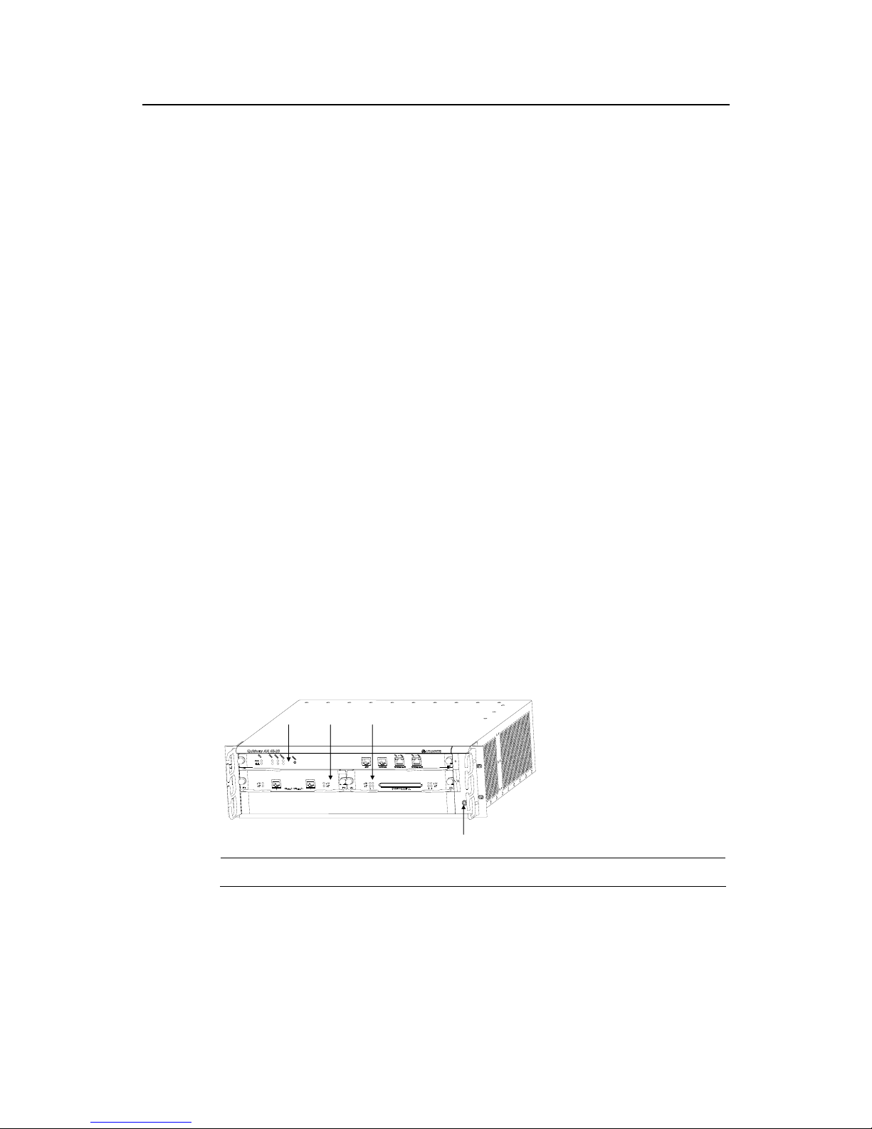
1.2.1 AR 46-20
(1)
(2) (3)
(4)
1) Main control unit (RPU) Slot0 2) FIC Slot1
3) FIC Slot2 4) ESD-preventive wrist strap port
Figure 1-1 Front panel of AR 46-20
Page 22
Installation Manual
Quidway AR 46 Series Routers Chapter 1 Router Overview
1-4
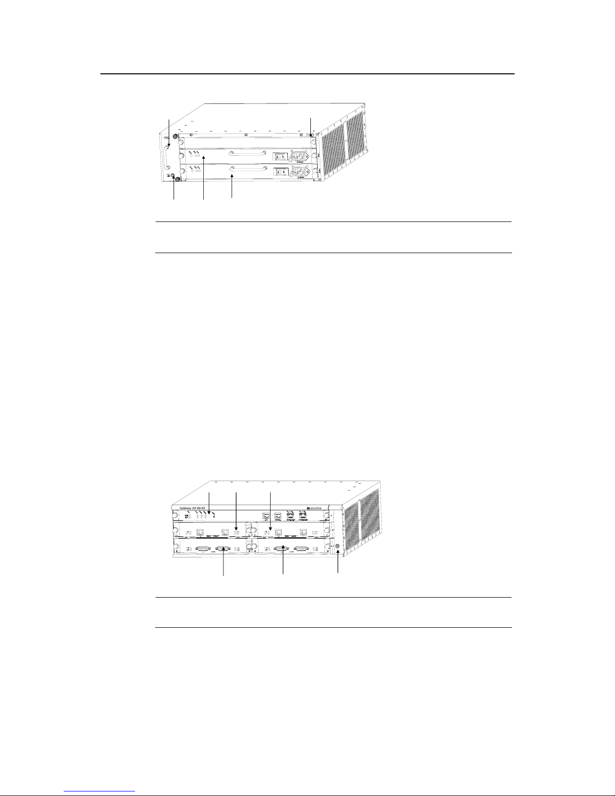
(1) (2)
(3)
(4)
(5)
1) Fan module 2) Grounding screw
3) ESD-preventive wrist strap port 4) Power supply unit (PSU) 1 (PWR1)
5) PWR2
Figure 1-2 Rear panel of AR 46-20
AR46-20 has three slots on the front panel, with slot 0 for the main control unit and slots
1 and 2 for FICs. At the bottom right of the front panel is an ESD-preventive wrist strap
port.
Two PSUs, working in 1+1 backup mode can be horizontally installed in AR 46-20 from
the rear of the chassis. The PSUs can be the ones providing DC or AC power supplies,
and you may make selection as needed. The fan module is located at the left rear. Both
PSU and fan module are hot swappable. At the bottom left of the rear panel is an
ESD-preventive wrist strap port and at the top right is a grounding screw.
1.2.2 AR 46-40
(1) (2) (3)
(6)
(4) (5)
1) RPU Slot0 2) FIC Slot1
3) FIC Slot2 4) FIC Slot3
5) FIC Slot4
6) ESD-preventive wrist strap port
Figure 1-3 Front panel of AR 46-40
Page 23
Installation Manual
Quidway AR 46 Series Routers Chapter 1 Router Overview
1-5
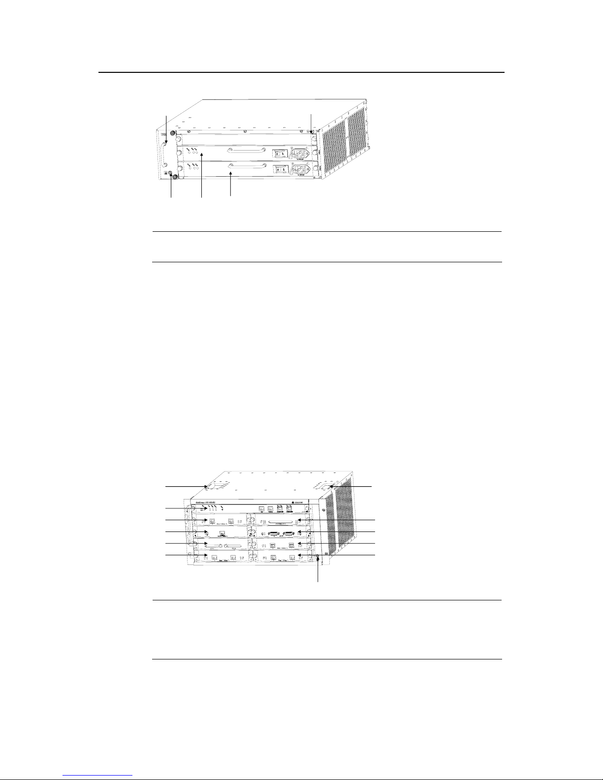
(1) (2)
(3)
(4)
(5)
1) Fan module 2) Grounding screw
3) ESD-preventive wrist strap port 4) Power supply unit (PSU) 1 (PWR1)
5) PWR2
Figure 1-4 Rear panel of AR 46-40
AR46-40 has five slots on the front panel, with slot 0 for the main control unit and slots
1 through 4 for FICs. At the bottom right of the front panel is an ESD-preventive wrist
strap port.
Two PSUs, working in 1+1 backup mode, can be horizontally installed in AR 46-40 from
the rear of the chassis. The PSUs can be the ones providing DC or AC power supplies,
and you may make selection as needed. The fan module is located at the left rear. Both
PSU and fan module are hot swappable. At the bottom left of the rear panel is an
ESD-preventive wrist strap port and at the top right is a grounding screw.
1.2.3 AR 46-80
(1)
(2)
(4)
(3)
(7)
(1)
(5)
(6)
(9)
(8)
(10)
(11)
1) Holes for holding chassis
2) RPU Slot0
3) FIC Slot1 4) FIC Slot2
5) FIC Slot3 6) FIC Slot4
7) FIC Slot5 8) FIC Slot6
9) FIC Slot7 10) FIC Slot8
11) ESD-preventive wrist strap port
Figure 1-5 Front panel of AR 46-80
Page 24
Installation Manual
Quidway AR 46 Series Routers Chapter 1 Router Overview
1-6
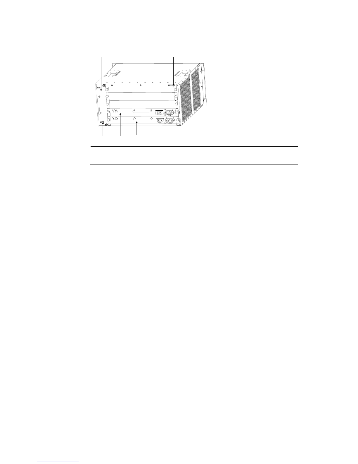
(1) (2)
(3)
(4)
(5)
1) Fan module 2) Grounding screw
3) ESD-preventive wrist strap port 4) PWR1
5) PWR2
Figure 1-6 Rear panel of AR 46-80
AR46-80 has nine slots on the front panel, with slot 0 for the main control unit and slots
1 through 8 for FICs. At the bottom right of the front panel is an ESD-preventive wrist
strap port.
Two PSUs, working in 1+1 backup mode, can be horizontally installed in AR 46-80 from
the rear of the chassis. The PSUs can be the ones providing DC or AC power supplies,
and you may make selection as needed. The fan module is located at the left rear. Both
PSU and fan module are hot swappable. At the bottom left of the rear panel is an
ESD-preventive wrist strap port and at the top right is a grounding screw.
Page 25
Installation Manual
Quidway AR 46 Series Routers Chapter 1 Router Overview
1-7
1.3 System description
Table 1-1 System description of AR 46-20/ 46-40/ 46-80
Item
AR 46-20
description
AR 46-40
description
AR 46-80 description
FIC slot
2 4 8
Fixed interface
2 10/100Mbps
Ethernet ports
1 AUX port
1 console port
2 10/100Mbps
Ethernet ports
1 AUX port
1 console port
2 10/100Mbps Ethernet ports
1 AUX port
1 console port
Processor
733MHz
Boot ROM 1024KB
SDRAM
Default: 256MB
Max: 512MB
NVRAM 512KB
Flash 32MB
Dimensions (W x D x H)
436.2 mm x 420 mm x
130.5 mm
436.2 mm x 420 mm x
130.5 mm
436.2 mm x 420 mm x 219.5
mm
Weight 28kg 18.7kg 18kg
AC
Rated voltage: 100-240V a.c.; 50/60Hz
Max. voltage: 90-264V a.c.; 50/60Hz
Max. current: 4.0A/2.0A/2.0A (AR 46-80/ 46-40/ 46-20)
Input voltage
DC
Rated voltage: -48- -60V d.c.
Max. voltage: -36- -72V d.c.
Max. current: 9.0A/5.0A/4.0A(AR 46-80/ 46-40/46-20)
Max. power 213W 126W 86W
Operating temperature 0 ~ 40oC
Relative humidity 10 ~ 90% (non-condensing)
Note:
SDRAM (Synchronous Dynamic Random Access Memory) is also known as the memory that stores the
communication data between the system and CPU.
NVRAM (Non-Volatile Random Access Memory) stores the abnormal alarm information
Flash memory functions as the major file storage medium to store application program files, abnormal
information, and configuration files.
Boot ROM stores the boot program file.
1.4 Introduction to General Modules
The general modules of AR 46 Series Routers include RPU, PSU (PWR), FAN, and
FICs, which will be described in the following subsections.
Page 26
Installation Manual
Quidway AR 46 Series Routers Chapter 1 Router Overview
1-8
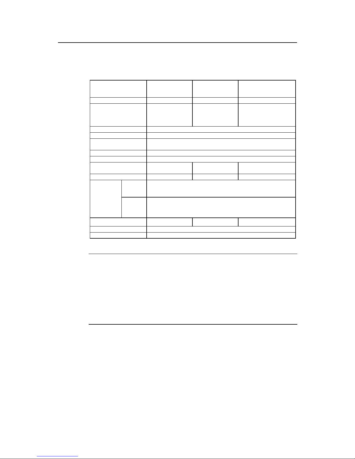
1.4.1 RPU
I. Functions
As the core of routers, RPU functions primarily to process protocols, forward low-speed
packets, control interfaces, and detect faults. The state monitoring information, such as
the operation states of FAN, PWR, and system can be shown directly via the LEDs on
the RPU, or reported to the Daemon for the monitoring on the network management
system. In addition, RPU also provides the hardware reset button RESET.
Following are the functions of RPU.
II. Appearance
Figure 1-7 RPU
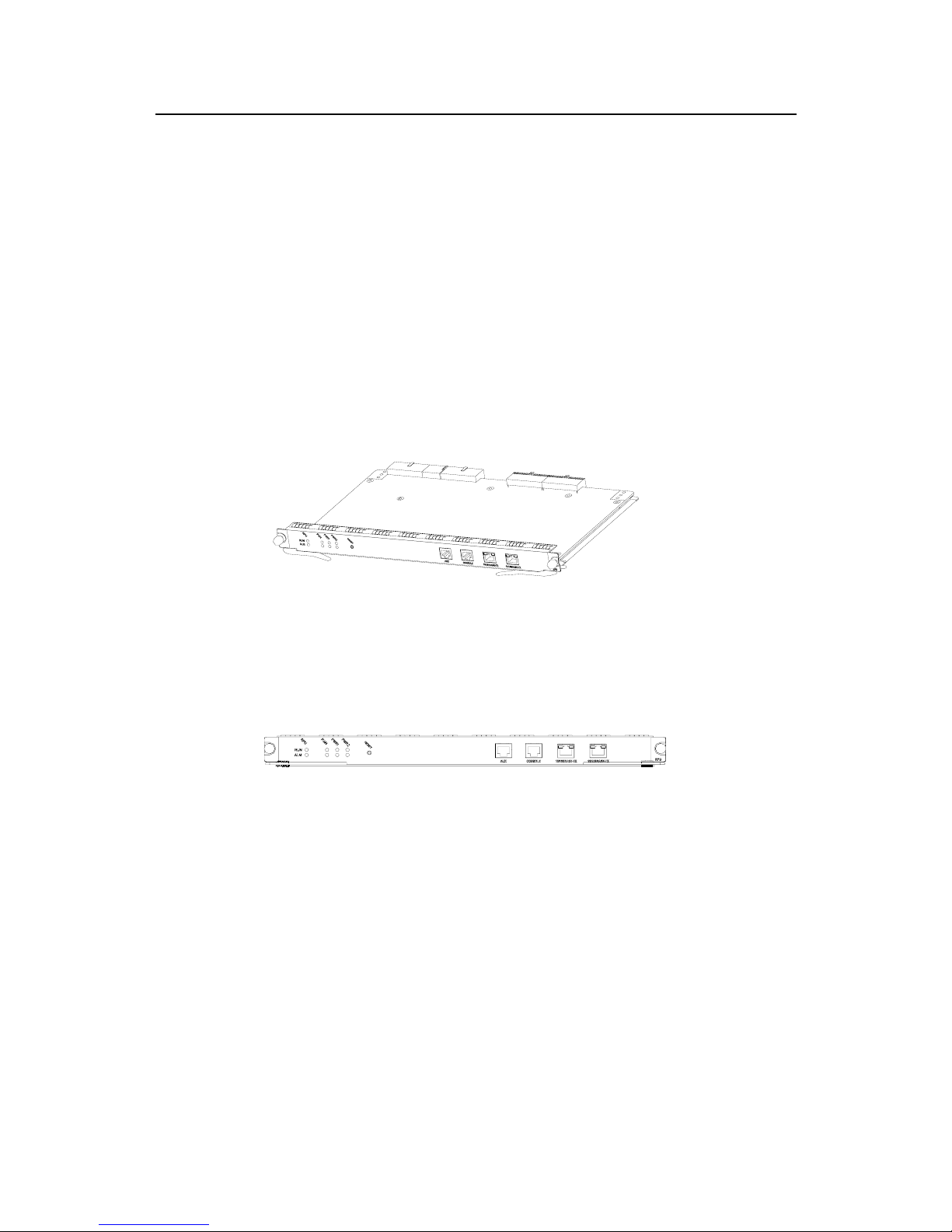
III. LED and button
Figure 1-8 Front panel of RPU
Page 27

Installation Manual
Quidway AR 46 Series Routers Chapter 1 Router Overview
1-9
Table 1-2 RPU LED and button description
LED and button Description
RPU
System operation LED. Blinking means the CPU is in normal operation,
constant ON or OFF means the CPU has failed.
FAN
FAN operation LED. Constant ON means the FAN is operating normally.
PWR1 PWR1 operation LED. Constant ON means PWR1 is operating normally,
and constant OFF means PWR1 is no in place or has failed.
RUN
(green)
PWR2 PWR2 operation LED. Constant ON means PWR2 is operating normally,
and constant OFF means PWR2 is no in place or has failed.
RPU System failure LED. ON means CPU has received an alarm signal for PWR
or FAN(due to overheating, for example).
FAN FAN failure LED. ON means the FAN is no in place or its rotation is
obstructed.
PWR1 PWR1 failure LED. ON means PWR1 has failed.
ALM (red)
PWR2 PWR2 failure LED. ON means PWR2 has failed.
RESET RPU hardware reset button.
LINK (green)
OFF means the link is not connected and ON means the link is connected.10/100BA
SE-TX
LED
ACT (yellow)
OFF means no data is being transceived on the interface and blinking
means data is being transceived.
IV. Interface
1) Console interface
Table 1-3 Console interface attributes
Attribute Description
Connector
RJ45
Interface standard
RS232
Baud rate
9600bps ~ 115200bps
9600bps by default
Supported service
Connect to the ASCII terminal
Connect to the serial interface of the local PC and run terminal emulation program on the
PC
Command Line Interface (CLI)
2) AUX interface
Table 1-4 AUX interface attributes
Attribute Description
Connector RJ45
Interface standard RS232
Baud rate 300 ~ 115200bps
Supported service
Modem dialup
Backup
3) Ethernet interface
Page 28

Installation Manual
Quidway AR 46 Series Routers Chapter 1 Router Overview
1-10
The RPU provides two 10/100Base-TX Ethernet ports on its panel (Ethernet 0/0/0 at
left and Ethernet 0/0/1 at right). Their attributes are listed in the following table.
Table 1-5 Ethernet interface attributes
Attribute Description
Connector
RJ45
Interface type
MDI
Supported frame
format
Ethernet_II
Ethernet_SNAP
Operating mode
10M/100Mbps auto-sensing
Full duplex/Half-duplex
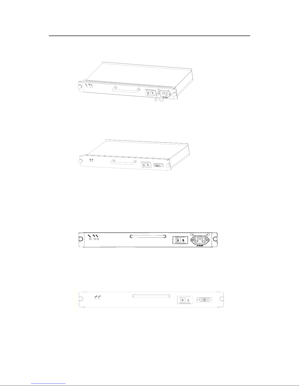
1.4.2 PWR
I. Functions
The power supply system of Quidway AR 46 Series Routers can work in either
single-power or dual-power mode. In dual-power mode, the two PWRs (either
supplying DC or AC power) function in a redundant way (that is, loading sharing mode).
The input interruption or failure of a PWR will not affect the operation of another PWR,
and this operating PWR will provide all the power required by the system.
Quidway AR 46 Series Routers provide two types of PWRs, i.e., AC PWR and DC
PWR, both providing the output power of 350W. PWR has the functions of overcurrent
protection and overvoltage protection.
You can connect the PWR to the backplane by inserting it from the rear of router
chassis. It is hot swappable and its switchover will not affect the ongoing system
operation.
Note:
If you want to install an AR 46 Series Router in a communication equipment room, you should make sure
that the power distribution cabinet can provide the lightning protection box or arrester against the current of
20KA and above.
Page 29
Installation Manual
Quidway AR 46 Series Routers Chapter 1 Router Overview
1-11
II. Appearance
Figure 1-9 AC PWR
Figure 1-10 DC PWR
III. LED
The following figure illustrates the front panel of AC PWR.
Figure 1-11 Front panel of AC PWR.
The following figure illustrates the front panel of DC PWR.
Figure 1-12 Front panel of DC PWR.
Page 30
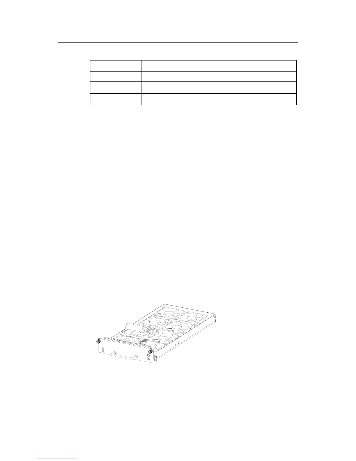
Installation Manual
Quidway AR 46 Series Routers Chapter 1 Router Overview
1-12
Table 1-6 PWR LED description
LED Description
ALM (red)
PWR failure LED. ON means PWR is not in place or has failed.
RUN (green)
PWR operation LED. Constant ON means PWR is operating normally, and OFF
means PWR has failed.
AC/DC OK (red)
PWR input LED (only for AC PWR). Constant ON means the normal voltage (85 ~
264V) is inputting, and OFF means the voltage input is not normal.
1.4.3 FAN
I. Functions
AR 46-20 and AR 46-40 are configured with six fans that are separated into three
groups, and AR 46-80 is configured with eight fans that are separated into four groups.
The two fans in a group are working in a redundant way. When all these fans are
working normally, the operating temperature of the system can be maintained in the
range of 0 to 55oC. As the failure of a fan will not affect the operation of other fans, the
system will still be able to operate in the normal temperature. The rotating speed of the
fans is controlled by the RPU and is in the range of 50% to 100%. The FAN controller
uses two parameters, i.e., low-temperature threshold and high-temperature threshold
to control the rotation speed of the fans, with the former corresponding to 100% rotating
speed and the latter corresponding to 50% rotating speed. The system will send out
rotation stop alarm signals in case any fan fails. The alarm and state LEDs of FAN are
located on the RPU front panel.
II. Appearance
The following figure shows the FAN appearance, taking AR 46-80 as an example.
Figure 1-13 FAN (AR 46-80)
Page 31

Installation Manual
Quidway AR 46 Series Routers Chapter 1 Router Overview
1-13
1.4.4 FIC
I. Ethernet interface cards
1-port 10 /100Base-TX Fast Ethernet (FE) interface card (RT-FIC-1FE)
2-port 10/100Base-TX FE interface card (RT-FIC-1FE)
1-port 10/100Base-FX Ethernet multi-mode fiber interface card (RT-FIC-1MFX)
1-port 10/100Base-FX Ethernet single-mode fiber interface card (RT-FIC-1SFX)
1-port 10/100/1000Base-FX Gigabitethernet single-mode fiber interface card (RT-FIC)
II. WAN interface cards
2-port enhanced multiprotocol sync/async serial interface card (RT-FIC-2SAE)
4-port enhanced multiprotocol sync/async serial interface card (RT-FIC-4SAE)
8-port enhanced multiprotocol sync/async serial interface card (RT-FIC-8SAE)
4-port ISDN BRI S/T interface card (RT-FIC-4BS)
8-port enhanced asynchronous serial interface card (RT-FIC-8ASE)
16-port enhanced asynchronous serial interface card (RT-FIC-16ASE)
1-port channelized T1/PRI interface card (RT-FIC-1T1)
2-port channelized T1/PRI interface card (RT-FIC-2T1)
4-port channelized T1/PRI interface card (RT-FIC-4T1)
1-port fractional T1 interface card (RT-FIC-1T1-F)
2-port fractional T1 interface card (RT-FIC-2T1-F)
4-port fractional T1 interface card (RT-FIC-4T1-F)
1-port channelized E1/PRI interface card (RT-FIC-1E1)
2-port channelized E1/PRI interface card (RT-FIC-2E1)
4-port channelized E1/PRI interface card (RT-FIC-4E1)
1-port fractional E1 interface card (RT-FIC-1E1-F)
2-port fractional E1 interface card (RT-FIC-2E1-F)
4-port fractional E1 interface card (RT-FIC-4E1-F)
1-port channelized T3 interface card (RT-FIC-1CT3)
Page 32

Installation Manual
Quidway AR 46 Series Routers Chapter 1 Router Overview
1-14
1-port channelized E3 interface card (RT-FIC-1CE3)
1-port 34Mbps ATM-E3 interface card (RT-FIC-1AE3)
1-port 44Mbps ATM-T3 interface card (RT-FIC-1AT3)
1-port 25Mbps ATM interface card (RT-FIC-1ATM-25M)
1-port ATM 155M multi-mode fiber interface card (RT-FIC-1ATM-OC3MM)
1-port ATM 155M single-mode fiber interface card (RT-FIC-1ATM-OC3SM)
1-port ATM 155M single-mode long-distance fiber interface card
(RT-FIC-1ATM-OC3SML)
1-port ADSL over PSTN interface card (RT-FIC-1ADSL)
2-port ADSL over PSTN interface card (RT-FIC-2ADSL)
1-port ADSL over ISDN interface card (RT-FIC-1ADSL-I)
2-port ADSL over ISDN interface card (RT-FIC-2ADSL-I)
1-port G.SHDSL interface card (RT-FIC-1G.SHDSL)
2-port G.SHDSL interface card (RT-FIC-2G.SHDSL)
4-port G.SHDSL interface card (RT-FIC-4G.SHDSL)
III. Voice interface cards
2-port voice subscriber circuit interface card (RT-FIC-2FXS)
2-port voice AT0 analog trunk interface card (RT-FIC-2FXO)
4-port voice subscriber circuit interface card (RT-FIC-4FXS)
4-port voice AT0 analog trunk interface card (RT-FIC-4FXO)
1-port E1 voice interface card (RT-FIC-E1VI)
1-port T1 voice interface card (RT-FIC-T1VI)
For more information about FICs, refer to “Chapter 8 FIC”.
Page 33

Installation Manual
Quidway AR 46 Series Routers Chapter 2 Installation Preparation
2-1
Chapter 2 Installation Preparation
2.1 General Site Requirements
AR 46 Series Routers are intended for indoor use. To ensure the proper working of the
routers and prolong their service life, the installation site should meet the requirements
described in the following subsections.
2.1.1 Temperature/Humidity Requirements
To ensure normal operation and prolong the service life of the Router, the equipment
room must maintain adequate temperature and humidity. Long-lasting high moisture is
prone to degrade the performance of the insulating material, which may result in
electric leakage, leading to metal erosion. If the equipment room is very dry, however,
the insulating shim will contract, leading to loosening of the fastening screws. Apart
from that, static electricity will be produced, which damages the Complementary
Metal-Oxide-Semiconductor (CMOS) circuit on the Router. If the equipment is always
very hot, the aging process of insulating materials will be accelerated, which will affect
the reliability of the Router and even the operational lifetime.
The following table lists the requirements of AR 46 Series Routers in temperature and
humidity.
Table 2-1 Temperature/Humidity requirements in the equipment room
Temperature Relative humidity
0oC to 40oC
10% to 90%
Note:
The values of the operating temperature and humidity in a router equipment refers to the values measured
at the position 1.5m above the floor and 0.4m ahead of the router rack, given there are no protective
boards in front or at the back of the router rack.
2.1.2 Cleanliness Requirements
Dust is harmful to the safe operation of the Router. Dust on the chassis may result in
static absorption, thus causing poor contact of the metal connection components or
Page 34

Installation Manual
Quidway AR 46 Series Routers Chapter 2 Installation Preparation
2-2
points. Especially under the condition of low indoor humidity, the dust is easier to be
absorbed, which not only shortens the operational lifetime of the equipment, but also
results in communication failure.
There should not be explosive, conductive, magnetic and corrosive dust in the
equipment room where Quidway AR 46 Series Routers are located, and the dust
concentration should meet the following requirements:
Table 2-2 Limitation on dust content in equipment room
Mechanical active material Unit Content
Dust particle particle/m³
≤3 x 10⁴
(No visible dust on desk in three
days)
Note: Dust particle Diameter ≥ 5µm
Besides the dust specifications, the equipment room of the Router should also meet the
rigorous requirements for the content of salt, acid and sulfide. These harmful gases
could accelerate the metal erosion and the aging process of some parts. The specific
limits of these harmful gases are given in the following table.
Table 2-3 Harmful gas limits in an equipment room
Gas Max. (mg/m3)
SO
2
0.2
H2S
0.006
NH
3
0.05
Cl
2
0.01
2.1.3 ESD Preventive Requirements
Despite careful considerations have been taken in preventing ESD in the design of the
Router, excessive static electricity may bring enormous damage to the card circuits and
even the entire Router.
On the communication network connected to the Router, the static electricity is
primarily introduced from the outside electrical fields, such as the outdoor high-voltage
power cable and lightning, and from the inside system, such as indoor environment,
floor material and the equipment frame. To avoid the damage caused by the static
electricity, you should ensure that:
z The equipment is well connected to earth.
z The equipment room is dust-proof.
z Keep adequate temperature and humidity.
z Wear the ESD-preventive wrist strap and clothes when contacting the circuit
board.
Page 35

Installation Manual
Quidway AR 46 Series Routers Chapter 2 Installation Preparation
2-3
z Place the removed circuit board upward on the ESD-preventive workbench, or into
a static shielded bag.
z Hold the circuit board by the outer edge when observing or moving it, so as to
avoid direct contact with the elements on it.
2.1.4 Electromagnetic Environment Requirements
All interference sources, no matter from the outside of the Router or the application
system, or from the inside, will influence the Router negatively in the conduction
patterns of capacitance coupling, inductance coupling, electromagnetic wave radiation,
and common impedance (including grounding system) coupling. To prevent the
interference, you should:
z Take effective measures against electricity net interference with the power supply
system.
z Do not use the working ground of the Router together with the grounding or
lightning protection grounding device of the power equipment. Separate them as
far as possible.
z Keep the Router far away from strong power wireless launchers, radar launchers
and high frequency and high-current equipment.
z Use electromagnetic shielding if necessary.
2.1.5 Lightning Protection Requirements
Despite careful considerations have been taken in lightning protection in the design of
the Routers and measures have been adopted, excessive-degree of lightning may still
damage the Routers. To achieve the best lightning protection effect, you are
recommended to:
z Keep the grounding wire of the PGND of the chassis in good contact with the earth
ground.
z Keep the grounding terminal of the AC power socket in good contact with the earth
ground.
z Add a lightning arrester for power supply onto the front end of the power input in
order to protect the power supply from lightning strikes in a more effective way.
z Add a special lightning protection facility at the input end of the signal cables in
order to protect the signal cables led to the outdoors, such as ISDN cable,
telephone cable, and E1/T1 cable, from lightning strikes in a more effective way.
2.1.6 Check Workbench
Following are the rules that you should observe when installing the Router:
z Leave enough clearance at the air intake vents and air exhausting vents to ensure
adequate ventilation of the router chassis.
Page 36

Installation Manual
Quidway AR 46 Series Routers Chapter 2 Installation Preparation
2-4
z Make sure that the workbench has a good ventilation system.
z Make sure that the workbench is stable enough and can support the weight of the
Router and the installation accessories.
z Make sure that the workbench has been well-grounded.
2.2 Safety Recommendations
When reading this manual, you should pay adequate attention to the following symbol
and the contents beneath it.
Caution
appears throughout this manual in procedures that, if performed incorrectly, might harm you or damage
the Router.
When installing or working on a Router, you are recommended to:
z Keep the Router far away from the heat sources and water/liquid.
z Make sure that the Router has been correctly grounded.
z Wear ESD-preventive wrist strap in the installation and maintenance, making sure
that the strap have good skin-contact.
z Do not hot swap the main control unit of the Router.
z Connect the cables to the ports appropriate to them. Above all, do not insert the
telephone cable (including the ISDN cable) into a serial port.
z Use laser cautions. Do not directly stare into the radiation aperture of the laser or
the fiber connector connected to it.
z Adopt Uninterrupted Power Supply (UPS).
2.3 Check Router and Accessories
After having confirmed that the installation conditions comply with the requirements,
please open the packing cases of the Router and check that the Router and the
accessories are completely consistent with the Purchase Contract. The following table
lists the parts and accessories that are essential to make an AR 46 Router function.
Page 37

Installation Manual
Quidway AR 46 Series Routers Chapter 2 Installation Preparation
2-5
Table 2-4 AR 46 Series Routers and accessories
Item Name Quantity Note
1
AR 46-20/4640/4680
mainframe
1 set
Router mainframe
2 Main control unit
1 PCS
-
3
PSU (AC or DC)
1/2 PCS To achieve redundancy, you must equip two PSUs.
4 Fan
1 -
5
FIC
0~2/4/8
You are available with abundant FIC options, but you can
equip AR 46-20 with only two pieces, AR46-40 with four,
and AR 46-80 with eight at maximum. You must specify
the ordered FIC type and quantity when place an order.
6 PGND wire
1 PCS
-
7 Console cable
1 PCS
-
8 Technology documentation 1 SET
Include printed documentation (Installation Manual for the
Router) and CD-ROM documentation.
9 Installation mechanical part 1 SET
-
10 Product package
1 SET
Include foam shockproof material, an external package
and plastic bags.
11 External cable suite
1 SET
Optional cables, including Ethernet cable, AUX cable,
synchronous/asynchronous serial cable, E1 cable, optical
cable, etc. You must specify the cable type and quantity
when placing the order. Otherwise, they will not be
provided.
Caution:
B68 cabinet is not included in the installation accessories, so you need to order it separately.
Please contact your agent if you have any question or problem.
2.4 Installation Tools and Meters and Equipment
1) Tool
z ESD-preventive wrist strap
z Static shielding bag
2) Cable
z Grounding wire and power cord
z Console cable
z Optional cables
3) Meter and equipment
z HUB or LAN Switch
z CSU/DSU (Channel Service Unit/Data Service Unit) or other DCE equipment
z Console terminal (it could be a common PC)
z Equipment related to the selected FICs
Page 38

Installation Manual
Quidway AR 46 Series Routers Chapter 2 Installation Preparation
2-6
z Multimeter
Caution:
AR 46 Series is not equipped with any installation tools, meters, or devices, and the user has to prepare
them.
Page 39

Installation Manual
Quidway AR 46 Series Routers Chapter 3 Router Installation
3-1
Chapter 3 Router Installation
3.1 Router Installation Flow
Mount the cabinet(optional)
Install PWR and FAN
Install RPU
Connect the PGND wire
Connect the power
cord
Connect the Router
to the console terminal
Verify installation
Power on the Router
Start
Normal?
Install FIC
Connect the Router to lAN
Connect the Router to WAN
Venify installation
End
Troubleshooting
Tum off the power swrtch
YES
NO
Mount the Router to
the specified location
Figure 3-1 Installation flow of AR 46 Series Routers
Caution:
Before installing a router, make sure that:
1) You have read Chapter 2 Installation Preparation carefully.
2) The requirements described in Chapter 2 Installation Preparation have been met.
Page 40

Installation Manual
Quidway AR 46 Series Routers Chapter 3 Router Installation
3-2
3.2 Install Cabinet
AR 46 Series Routers can be mounted in B68 cabinet provided by Huawei
Technologies. For details about B68 cabinet installation, refer to “Appendix B B68
Cabinet Installation”.
If you mount a router in a cabinet provided by some other manufacturer or do not mount
it in a cabinet at all, you can skip this part.
3.3 Mount Router to a Specified Place
3.3.1 Rack Mount Router
AR 46 Series Routers are designed to fit the 19-inch standard rack. The following table
describes their dimensions.
Table 3-1 AR 46 Series Router dimensions
Model Dimensions (mm)
AR 46-20 (W x D x H)
436.2 x 420 x 130.5
AR 46-40 (W x D x H) 436.2 x 420 x 130.5
AR 46-80 (W x D x H) 436.2 x 420 x 219.5
Take the following steps to mount a Router.
Step 1: Confirmation before mounting.
Ensure the rack has been well fixed. The installation position for the Router has been
well arranged and there is no obstacle inside the rack or around. Ensure the router is
ready for installation and has been carried to a place near the rack and convenient for
moving.
Step 2: Fix the mounting brackets (attached with a fixed cabling rack) onto both sides of
the chassis with a Phillips screwdriver. (Skip this step, if you do not fix the router on the
rack.)
Step 3: Lift the Router a little higher than the shelf or guides in the rack and put the
Router on the shelf/guides and push it into the rack. (Since AR 46-80 Router is rather
heavy, it needs two people to carry from both sides.)
Step 4: Fix the Router in the rack by fixing the mounting brackets with the proper pan
head screws and make sure the router is level and stable. (Skip this step, if you do not
fix the router on the rack.)
Page 41

Installation Manual
Quidway AR 46 Series Routers Chapter 3 Router Installation
3-3
(1)
(3)
(1)
(2)
(2)
1) Mounting screws 2) Mounting brackets (carrying cabling racks)
3) Guides
Figure 3-2 Mount a Router on a rack
3.3.2 Bench-Mount Router
In most cases, 19-inch standard rack is not available. People mount the routers on
clean bench more often. This mounting method is simple. Please pay attention to the
following items:
z Keep the workbench stable and well grounded.
z Leave the clearance of 10cm around the Router for heat dissipation.
z Never put heavy things on the Router.
3.4 Install the General Modules
The tasks of general module installation include the installations of RPU, PWR, and
various FICs. For the installation procedures of RPU, PWR, and FAN, refer to “Chapter
6 Router Hardware Maintenance”. For the installation procedures of FIC, refer to
“Chapter 8 FIC”.
3.5 Connect the PGND
Warning:
The normal connection of PGND wire for the Router is the essential safeguard against the lightning shocks
and interference. Therefore, you must first correctly connect the PGND wire when installing and using the
Router.
Page 42

Installation Manual
Quidway AR 46 Series Routers Chapter 3 Router Installation
3-4
AR 46 Series Routers provide a separate PGND screw. You must securely connect the
PGND to the ground, ensuring the faradism and leakage power to be channeled into
the earth ground. Thus, the anti-EMI capability of the entire Router can be significantly
improved. The PGND also provides protection against the high voltage of lightning
shocks caused by external network lines like E1/T1 line and ISDN/PSTN line.
The PGND screw is located at top right-rear of the chassis and identified by a
grounding mark, as shown in the following figure:
(1)
1) Grounding screw
Figure 3-3 PGND grounding screw of Router
Connect the ground screw to the earth ground using a PGND cable, requiring a
grounding resistance less than 5-ohm. If you install the Router in a 19-inch standard
rack, you must also ground the rack.
Warning:
You must well ground the operating router (that is, securely connect the PGND in case the unreliable
grounding results in damages on the Router and even the peer equipment in the lightning activity period.
3.6 Connect Power Cord
AR 46 Series Routers have AC-powered and DC-powered models. You can make your
selection as needed. These models have the same features and functions, except for
PWR type.
Page 43

Installation Manual
Quidway AR 46 Series Routers Chapter 3 Router Installation
3-5
3.6.1 Connect AC Power Cord
I. AC power supply
AC power input range: 100 to 240V, 50/60Hz AC.
The following figure shows the power socket of an AC-input Router.
(1)
(2) (3)
1) Cable-retention clip 2) Power switch
3) AC input
Figure 3-4 Partial appearance of AC power socket
II. Recommended AC power socket
The user is recommended to use a 3-line single-phase power socket with a grounding
terminal, which should be reliably connected to the ground in the building. Normally, the
grounding terminal of the power supply system in a building was buried in the ground
during the construction and cabling. The user must make sure that the power supply for
the building has been well grounded before connecting the AC power cord.
III. Connect AC Power Cord
Step 1: Check that the PGND wire has been correctly connected to the ground.
Step 2: Insert one end of the power cord accompanying the Router into the power
socket on the Router’s rear panel, fix the cable onto the cable-retention clip with a cable
strap, and connect the other end of the cable to the AC outlet that provides power
supply.
Step 3: Check that the POWER LED on the front panel of the Router is ON, which
means the power cord connection is correct.
3.6.2 Connect DC Power Cord
I. DC power supply
DC power input range: -48 to -60V DC
Page 44

Installation Manual
Quidway AR 46 Series Routers Chapter 3 Router Installation
3-6
The following figure shows the power socket of a DC-input Router.
(1)
(2)
1) Power switch 2) DC input
Figure 3-5 Partial appearance of DC power socket
II. Connect DC Power Cord
Figure 3-6 DC power cord
Table 3-2 DC power cord pinouts
-48 power supply side Router side
X2 (blue -48V lead)
X1.A1
X3 (black BGND lead)
X1.A3
Step 1: Check that the PGND wire has been correctly connected to the ground.
Step 2: Connect one end of the DC power cord to the power socket on the rear panel of
the router chassis and the other end to the –48V DC power supply.
Warning:
In case of wrong connection, carefully read the label on the DC power cord before making connection.
Step 3: Check that the POWER LED on the front panel of the Router is ON, which
means the power cord connection is correct.
Page 45

Installation Manual
Quidway AR 46 Series Routers Chapter 3 Router Installation
3-7
3.7 Connect the Console Terminal
I. Introduction to console port
Each AR 46 Series Router provides an RS232-comliant asynchronous serial console
port (CON), through which the user can configure the Router. For the console interface
attributes, refer to the section “1.5.1 RPU”.
II. Console cable
Console cable is an 8-core shielded cable. At one end of the cable is a crimped RJ45
connector that is to be plugged into the console port of the Router. At the other end of
the cable are a DB9 (female) connector and a DB25 (female) connector. You can plug
either of them into the serial port on the console terminal as needed.
The following figure illustrates the console cable.
Figure 3-7 Console cable
III. Connect console cable
Before you can configure the Router at the console terminal, connect the console cable
in the following steps:
Step 1: Select a console terminal. Console terminal can be a standard ASCII terminal
possessing an RS232 serial port, or a regular PC, but the latter is often used.
Step 2: Connect the cable. Power off the Router and console terminal, and connect the
RS232 serial port to the console port on the RPU via a console cable.
Power on the Router after verifying the installation. If the Router is working normally,
the system will display the router boot information on the console terminal. For more
information about that, refer to “Chapter 4 Booting and Configuration”.
Page 46

Installation Manual
Quidway AR 46 Series Routers Chapter 3 Router Installation
3-8
3.8 Connect Router to LAN
I. Introduction to Ethernet interface
AR 46 Series Routers provide the fixed 100BASE-TX FE interface. For details of its
attributes, refer to the section “1.5.1 RPU".
II. Ethernet cable
100BASE-TX Ethernet interface usually adopts the category 5 twisted-pair for
connection, as shown in the following figure.
Figure 3-8 Ethernet cable
Ethernet cables fit into two categories, i.e., straight-through cables and crossover
cables.
z Straight-through cable: The wire sequences of the twisted pairs crimped in the
RJ45 connectors at both ends are the same. It is used for connecting a terminal
device (e.g., PC and router) to a HUB or LAN Switch. The cables delivered with
the router are straight-through cables.
z Crossover cable: The wire sequences of the twisted pairs crimped in the RJ45
connectors at both ends are different. It is used for connecting two terminal
devices (e.g., PC and router). Users can make it as needed.
Note:
When preparing network cables, please use shielded twisted-pair (STP) cables so long they are available
for the sake of electromagnetic compatibility.
III. Connect Ethernet cable
Page 47

Installation Manual
Quidway AR 46 Series Routers Chapter 3 Router Installation
3-9
Caution:
1) You must connect a cable to the interface with the appropriate mark. Misplugging is prone to impair the
interface card and even damage the router mainframe.
2) When connecting to a LAN Switch, insert the cable to the 10/100BASE-T port identified by MDIX.
Follow these steps to connect an Ethernet cable, to the 10/100BASE-TX port on the
RPU for example.
Step 1: Use a crossover cable to connect the Router to a PC or another Router by
connecting one end of the cable to the Ethernet port on the Router and the other end to
the PC or the peer router. Use a straight-through cable to connect the Router to a HUB
or LAN Switch by connecting one end of the cable to the Ethernet port on the Router
and the other end to the HUB or the LAN Switch.
Step 2: View the LED of 10/100BASE-TX port. If the link has been connected, the green
LED will light.
3.9 Connect Router to WAN
AR 46 Series Routers provide various WAN interfaces and the one provided by the
RPU is AUX interface, the connection of which will be described in details in the coming
subsections. For the connection of the WAN interface on an FIC, refer to the relevant
contents in “Chapter 8 FIC”.
3.9.1 Connect the AUX Port to Modem
I. Introduction to AUX interface
AUX is an RS232-compliant asynchronous serial interface that can provide backup for
a WAN interface. Usually, it functions to provide dial connection. In case of console
failure, AUX can function as a console interface. For the AUX interface attributes, refer
to the section “1.5.1 RPU”.
II. AUX cable
AUX cable is an 8-core shielded cable. At one end of the cable is an RJ45 connector
that can be plugged into the console port of the Router. At the other end are DB9 (male)
connector and DB25 (male) connector. You can plug either of them into the serial port
of modem as needed. The following figure illustrates the AUX cable.
Page 48

Installation Manual
Quidway AR 46 Series Routers Chapter 3 Router Installation
3-10
Figure 3-9 AUX cable
III. Connect the AUX cable
Follow these steps to connect the AUX cable.
Step 1: Insert the RJ45 connector of the cable into the AUX port on the RPU.
Step 2: Insert the DB25 or DB9 connector into the serial port of the analog modem.
AUX port is usually used for remote configuration or dial-up backup. Therefore, you
need to connect the local modem to the remote modem via PSTN and then to the
remote equipment. For the configuration procedures, refer to VRP Operation Manual.
3.10 Verify Installation
During router installation, you must verify the installation each time you power on the
Router, making sure that
z Enough clearance has reserved around the Router for adequate dissipation and
the cabinet is stable enough.
z The correct power supply is used.
z The connection of the PGND wire of the Router is correct and secure.
z The connections with other devices, such as the console terminal, are correct.
Note:
It is very important for you to check the router installation, as the secure connection, well grounding, and
use of the correct power supply are essential to the normal operation of the Router.
Page 49

Installation Manual
Quidway AR 46 Series Routers Chapter 4 Booting and Configuration
4-1
Chapter 4 Booting and Configuration
4.1 Boot a Router
4.1.1 Establish Configuration Environment
When configuring a router for the first time, you can only use Console port or AUX port.
This section introduces the local and remote configuration environment establishment
for your reference
I. Connect the Router to a configuration terminal
To set up the local configuration environment, RJ45 connector of the console cable
needs to be connected to the console port on the Router, and DB25 connector or DB9
connector to the serial interface of a PC, as shown in Figure 4-1.
RS232 serial port
C ons ole cab le
Console port
Quidway AR46-20
PC
RS232 serial port
C ons ole cab le
Console port
Quidway AR46-20
PC
Figure 4-1 Local configuration through CON port
II. Set the parameters of configuration terminal
Step 1: Start the configuration terminal and set up a new connection
If the configuration is performed through a PC, the terminal emulation program (such as
Terminal of Windows3.1 and HyperTerminal of Windows95/98/NT) should be run in the
PC to set up a new connection. As shown in Figure 4-2, enter a name for the new
connection and press <OK> button.
Page 50

Installation Manual
Quidway AR 46 Series Routers Chapter 4 Booting and Configuration
4-2
Figure 4-2 New connection
Step 2: Set terminal parameters
Parameters of the HyperTerminal of Windows98 are set as follows:
z Select a connection port. While implementing the local configuration, select the
serial interface to be connected in the Connect Using box, as shown in Figure 4-3.
Please notice that the selected serial interface should be consistent with the actual
serial interface connected by the console cable.
Page 51

Installation Manual
Quidway AR 46 Series Routers Chapter 4 Booting and Configuration
4-3
Figure 4-3 Setting the connection port in the local configuration
z Setting serial interface parameter. As shown in Figure 4-4, in the properties dialog
box of the serial interface, the parameters are set as follows: Baud rate 9600, Data
bits 8, Parity check None, Stop bits 1, and Flow control None. Click the <OK>
button to return to the HyperTerminal interface.
Figure 4-4 Setting serial interface parameters
Page 52

Installation Manual
Quidway AR 46 Series Routers Chapter 4 Booting and Configuration
4-4
z Set HyperTerminal properties. Select [Property/Settings] on the HyperTerminal
and enter the property setting window, shown as Figure 4-5. Select VT100 or auto
detection as terminal simulation type, press [Ok] and return to the HyperTerminal
window.
Figure 4-5 Setting terminal type
4.1.2 Power on the Router
I. Check before power-on
Perform the following check items before powering on a router:
z Whether the power cord and ground wire are correctly connected.
z Whether the voltage of the power supply complies with the requirement of the
Router.
z Whether the console cable is correctly connected, whether the PC or terminal for
configuration is started, and whether the settings are done.
Page 53

Installation Manual
Quidway AR 46 Series Routers Chapter 4 Booting and Configuration
4-5
Warning:
Before switching on the power, locate the power switch in the equipment room, so that, in case of an
electrical accident, power can be quickly turned off.
II. Power on the Router
Turn on the power switch of the Router.
III. Check/Operate after power-on
After powering on the Router, check
z Whether the LEDs on the front panel are normal.
For the meaning of indicators under normal operation, see the description in Section
1.5 Versatile Module.
z Whether the configuration terminal display is normal.For the local configuration,
the booting interface displays on the configuration terminal after the Router is
powered on (refer to “Section 4.1.3 Booting Process” in this manual).
When booting (POST) is done, press <Enter>. After the command line prompts
<Quidway>, you can start configuration.
4.1.3 Startup Process
I. Self-test on SDRAM
During the process of powering on the router or resetting the router, the configuration
terminal yields the following output first:
Do you want to go on checking sdram? Yes or not(Y/N)
This information asks if you want to check the SDRAM. If you press <N>, the system
will skip the SDRAM checking.
Page 54

Installation Manual
Quidway AR 46 Series Routers Chapter 4 Booting and Configuration
4-6
Note:
SDRAM checking is the responsibility of testing personnel and consumes a lot of time. Generally, it is
skipped. Normally, it takes 8 seconds to check 32M memory, so on and so forth. (About 2 seconds) after
the prompt appears, press <y> to start SDRAM checking. If the SDRAM is normal, the system yields the
following output:
test SDRAM...OK
If you press no key during 5 seconds after that, the system responds the default setting (N/n) and exits
from SDRAM self-test.
II. Display system information
And then, the following information displays on the screen:
Starting...
*******************************************************
* *
* Switching Routing Platform 8060 Bootrom, Ver 1.07 *
* *
*******************************************************
Copyright(C) 2001-2005 by HUAWEI TECHNOLOGIES CO.,LTD.
Creation date: Jul 14 2003, 10:54:22
CPU type : IBM750FX-DD2.2
CPU L2 Cache : 512KB
CPU Clock Speed : 625MHz
BUS Clock Speed : 125MHz
Memory Size : 256MB
Press Ctrl+B to enter Boot Menu... 0
If you press <Ctrl+B> within 4 seconds, the system will enter Boot menu. Boot menu
mainly provides application downloading and executing. For details about Boot menu,
refer to Chapter 5.
If you do not press<Ctrl+B>, the system will take the next step.
Page 55

Installation Manual
Quidway AR 46 Series Routers Chapter 4 Booting and Configuration
4-7
Note:
The system provides Boot ROM master system automatic updating function. Before executing an
application, if it finds the Boot ROM master system version is different from that recorded in the Boot ROM
chip, it will automatically update the Boot ROM master system and reset it. The following information will
display:
Update Bootrom...done!
system will reboot...
III. Select booting device and download applications
If you do not press<Ctrl+B>, the Boot ROM program will automatically select a booting
device according to the configuration of a user and read the application files from the
corresponding device into SDRAM. If a user configures to boot with Flash, the terminal
screen will yield the following information:
Auto-booting...
Booting From Flash...
The Boot File is < flash:/8060.bin >
IV. Decompress Application
If the application files read into the SDRAM pass the checking, they will be
decompressed. And the terminal screen displays the following information:
Begin
Decompressing ............................................................
Packet Decompress is completed !
V. Initialize the system
After decompression, the Boot ROM program ends and the depressed application will
be executed. The terminal screen displays the following information:
Booting...
Be Sure The Baudrate Be Set To 9600bps!
Be Sure The Baudrate Be Set To 9600bps!
GT64260 Version->[B].
usrRoot() end
leave BSP
root begin...
Init 28F128...
Begin to start the system, please waiting ......
... ...
... ...
Page 56

Installation Manual
Quidway AR 46 Series Routers Chapter 4 Booting and Configuration
4-8
line Con 0 is available.
Press ENTER to get started.
The above information indicates the system initialization is done and the router
operates normally. You can press <Enter> to enter the command line and start
configuring the router. After you press <Enter>, the terminal screen displays the
following information:
<Quidway>
4.2 Router Configuration Fundamentals
4.2.1 Basic Configuration Procedure
In general, the configuration steps are as follows:
Step 1: Before configuring a Router, the networking requirements have to be made
specific and detail. They include networking purpose, the role of the Router in the
network, the division of subnets, the type of the WAN and transmission medium, the
network security policy and reliability.
Step 2: Based on the above requirements, draw a clear and detail networking diagram.
Step 3: Configure the WAN interface of the Router. Firstly, configure the physical
operating parameters (such as synchronous/asynchronous serial interface, baud rate
and synchronous clock) of the interface according to the transmission medium of the
WAN. For the dial-up interface, you need to configure DCC parameters for it. Secondly,
configure the link layer protocol encapsulated on the interface and the related operating
parameters according to the type of the WAN.
Step 4: Configure the IP addresses or IPX network number of all the interfaces of the
Router according to the division of the subnets.
Step 5: Configure the routes. If it is necessary to enable the dynamic routing protocol,
configure the related operating parameters of the protocol.
Step 6: If there is any special security requirement, perform the security configuration
for the Router.
Step 7: If there is any special reliability requirement, perform the reliability configuration
for the Router.
Refer to VRP3 Operation Manual for detailed introduction of the protocols or function
configuration the Router.
Page 57

Installation Manual
Quidway AR 46 Series Routers Chapter 4 Booting and Configuration
4-9
4.2.2 Command Line Interface
I. Characteristics of the command line interface
The command line interfaces provided by Quidway AR 46 Series Routers include a
series of configuration commands, through which a user can configure and manage the
router. The command line interface has the following features:
z Performs the local configuration through CON port.
z Performs the local or remote configuration through the Telnet command, which
can be used to directly log on and manage other Routers.
z Users can enter <?> at any time to get online help.
z Provide prompt and help information for user’s convenience.
z Provide network diagnostic tools, such as Tracet and Ping, to quickly diagnose the
availability of the network.
z Provide all kinds of detailed debugging information to diagnose network faults.
z The command line interpreter adopts fuzzy search for the keywords of the
command. Any conflict-free keyword will be interpreted. For example, for the
display command, you can just enter <dis>.
II. Command line interface
Quidway AR 46 Series Router command line interface provides a rich set of
configuration commands, which are grouped in system view. A group corresponds a
view (see VRP3 Operation Manual for details). You can switch between different views
through commands. Normally, only some specific commands can be executed in a
certain view, although some common commands (such as ping, display
current-configuration, and interface) can be used in every view.
4.2.3 Slot Arrangement and Interface Numbering Rules
Quidway AR 46 Router supports various interfaces, such as CON port, AUX port,
Ethernet port, (synchronous/asynchronous) Serial port, Asynchronous port, and voice
port (FXO/FXS). The interfaces are configured in the order of sequence number.
1) Slot arrangement
Figure 4-6 AR 46-20 Router slot arrangement
Page 58

Installation Manual
Quidway AR 46 Series Routers Chapter 4 Booting and Configuration
4-10
Figure 4-7 AR 46-40 Router slot arrangement
Figure 4-8 AR 46-80 Router slot arrangement
2) Interface numbering rule
AR 46 interfaces are numbered in three dimensions. The rules are as follows:
z The interfaces are numbered in the interface-type X/Y/Z format, in which, interface
specifies the interface type (as serial, asynchronous, ethernet or ATM, etc.), X
specifies the slot number, Y specifies the pinch board number (or is fixed as 0
when there is no pinch board), and Z specifies the interface sequence number.
z As shown in the above figure, different interfaces of an interface module share the
same slot number X.
z For every interface, Y starts from 0 and Z indicates the interface sequence (from
left to right) on the interface module.
z For example, 1FE and 2FE modules are installed in SLOT1 and SLOT2 of AR
46-20 Router respectively. The Ethernet ports are arranged as follows:
z Fixed Ethernet ports are Ethernet 0/0/0 and Ethernet 0/0/1;
z Ethernet port of 1FE module is Ethernet 1/0/0;
z Ethernet ports of 2FE module are Ethernet 2/0/0 and Ethernet 2/0/1.
Page 59

Installation Manual
Quidway AR 46 Series Routers Chapter 4 Booting and Configuration
4-11
Every interface is configured in special view. For details, refer to VRP3 Operation
Manual Volume I (V3.X).
Page 60

Installation Manual
Quidway AR 46 Series Routers Chapter 5 Software Maintenance
5-1
Chapter 5 Software Maintenance
5.1 Overview
The files managed by the Router are of 3 types:
z Boot ROM program files
z Application program files
z Configuration files
The maintenance of the Router involves mainly the three aforementioned types of files.
Only the software maintenance functions listed in Boot menu, for example upgrading of
Boot ROM files and application files, are discussed here. For details about other
functions, see VRP3 Operation Manual.
Caution:
Upgrade the Router software sensibly and in a proper way. It is recommended to upgrade the software
under the guidance of the technical support personnel.
5.2 Boot Menu
Boot main menu and Boot sub-menu will be used during the maintenance of the router
software. Boot sub-menu can upgrade and start Boot ROM program. While Boot main
menu upgrades and starts application program.
Build up a configuration environment according to the section 4.1, and then boot the
Router. The following information will be displayed on the terminal screen:
Do you want to go on checking sdram? Yes or not(Y/N)
Enter <N> and the following information will be displayed on the terminal screen:
Press CTRL+A to Stop AutoBoot!
Starting...
Press <Ctrl+A> in five seconds after “Starting...” pops up, then the system enters Boot
sub-menu.
Page 61

Installation Manual
Quidway AR 46 Series Routers Chapter 5 Software Maintenance
5-2
Note:
1) In order to access the Boot sub-menu, you shall press <Ctrl+A> within five seconds after the information
“starting…” appears. Otherwise the system will directly enter Boot main menu if no error is found in system
checks.
2) If you do not press <Ctrl+A> as required, then the system will check the code for Boot main system
when Boot sub-system starts. If errors are found in checks or caused by other faults during checks, the
system may enter Boot sub-system. Otherwise, it directly enters Boot main system.
5.2.1 Boot Sub-menu
The following information will be displayed on the terminal screen when the system
enters Boot sub-system successfully.
============<SMALL-BOOTROM MENU(Ver 1.07)>=============
| <1> Modify Serial Interface Parameter |
| <2> Update LargeBootrom |
| <3> Boot main system |
===========================================================
Enter your choice(1-3):
I. Modifying serial port parameters
Step 1: Enter <1> in Boot sub-system and the system will begin to change baudrate of
the serial port on RPU card, as will reduce the time to load necessary files. The system
prompts the following information:
========================<BAUDRATE SET>=========================
|Note: Change The HyperTerminal's Baudrate Accordingly. |
|-----------------------<BaudrateAvaliable>------------------ |
| <1> 9600(Default) |
| <2> 19200 |
| <3> 38400 |
| <4> 57600 |
| <5> 115200 |
================================================================
Enter Your Choice(1-5):
The information indicates you to choose desired baudrate. By default, the baudrate is
9600 bps. Step 2: Select a target item and press <Enter>. When you select <5>, the
system prompts
Enter your choice(1-5): 5
Change The BaudRate On PC Side First!
Page 62

Installation Manual
Quidway AR 46 Series Routers Chapter 5 Software Maintenance
5-3
Step 3: Select [File/Attributes] at HyperTerminal in the configuration PC and press
<Configuration> in the dialog box. In the dialog box, change the baudrate to a desired
value and press <OK>. Suppose the baudrate here is 38400. See 4.1.1 2 Setting
parameters for configuration PC for details.
Step 4: Disconnect the system and resume dialup, to make the new parameter take
effect.
The Current BaudRate is 115200
Note:
You should reset the HyperTerminal baudrate to the default value 9600bps when upgrading Boot ROM by
changing rate downloading files, to prevent that no output information is prompted on the terminal screen
after sytem startup or system restart.
II. Upgrading Boot main system (LargeBootrom) through serial port
Enter <2> in Boot sub-system and choose to upgrade Boot main system via Xmodem.
See 5.3.1 Upgrading Boot Main System, for more details.
III. Starting Boot main system
Enter <3> in Boot sub-system and the system will then copy the files in Boot main
system into SDRAM. It will also decompress and start the files. Then the system will
start Boot main menu.
5.2.2 Boot Main Menu
The following is prompted on the terminal screen after the system enters Boot main
system.
*******************************************************
* *
* Switching Routing Platform 8060 Bootrom, Ver 1.07 *
* *
*******************************************************
Copyright(C) 2001-2005 by HUAWEI TECHNOLOGIES CO.,LTD.
Creation date: Jul 14 2003, 10:54:22
CPU type : IBM750FX-DD2.2
CPU L2 Cache : 512KB
CPU Clock Speed : 625MHz
BUS Clock Speed : 125MHz
Page 63

Installation Manual
Quidway AR 46 Series Routers Chapter 5 Software Maintenance
5-4
Memory Size : 256MB
Press Ctrl+B to enter Boot Menu... 0
If you press <Ctrl+B> at this time, the system will enter Boot main menu.
Note:
Press <Ctrl+B> in four seconds after startup to enter Boot main menu. Otherwise the system will start host
program in default mode.
The system will first prompt the following information for you to enter Boot ROM
password:
password:
If the password (the initial password 8060) is correct, the system shows the main menu
as listed in the following. If you enter incorrect password for three times consecutively,
the system will restarts.
MAIN MENU
=====================<MAIN-BOOTROM MENU>=======================
| <1> Boot With Default Mode |
| <2> Boot From Flash |
| <3> Enter Serial SubMenu |
| <4> Enter Ethernet SubMenu |
| <5> Modify Flash Ddescription Area |
| <6> Modify Bootrom Password |
| <7> Reboot
===============================================================
Enter your choice(1-7): _
Note:
To set Flash description area, enter <5> when the system starts for the first time.
If you use Flash for the first time and reading or writing Flash is required, Flash will be formatted first. Then
the following informatio will be prompted:
Formatting Flash, please waiting several minutes...done
I. Starting host program in default mode
Enter <1> in Boot main menu and the system will first read Flash description area to get
start flag (from Flash or from hardware disk) and start file names. Then it downloads
Page 64

Installation Manual
Quidway AR 46 Series Routers Chapter 5 Software Maintenance
5-5
host program files to memory according to start flag and start file names. The system
decompresses and starts the files, and the terminal will display:
Boot With Default Mode
Booting From Flash...
The Boot File is < flash:/8060.bin >
Note:
The system will restart when errors occur in Flash description area data or start files. In this case, please
enter Boot main menu to modify Flash description area data or to download start files. Currently the AR 46
only supports starting Boot main menu from Flash.
II. Starting application program from Flash
Enter <2> in Boot main menu and the system will first read Flash description area to get
Flash start file names. Then it downloads host program files to memory according to
start file names. The system decompresses and starts the files. The following
information is prompted on the terminal screen:
Booting from Flash
Decompress Image..................................OK!
Starting at ...
III. Entering seial port sub-menu
Enter <2> in Boot main menu and the system will enter serial port sub-menu. The
following information is shown on the terminal screen:
Boot From Serial Port
======================<SERIAL SUB-MENU>========================
| <1> Download Program To SDRAM And Run |
| <2> Download Program To Flash |
| <3> Change Boot Parameter |
| <4> Exit To Main Menu |
===============================================================
Enter your choice(1-4): _
1) Downloading via serial port application files to memory and starting them
Enter <1> in serial port sub-menu and the system will download via serial port
application files from the configuration PC to memory using Xmodem protocol. It then
decompresses them and runs start file upon skipping to program ingress. Refer to
Page 65

Installation Manual
Quidway AR 46 Series Routers Chapter 5 Software Maintenance
5-6
5.2.1 II. Upgrading Boot main system (LargeBootrom) through serial port, for loading
details.
2) Downloading via serial port application files to Flash
Enter <2> in serial port sub-menu and the system will download via serial port
application files to Flash using Xmodem protocol.
3) Modifying serial port parameters
Enter <3> in serial port sub-menu to modify baudrate of the serial port on RPU card.
The following information is displayed:
========================<BAUDRATE SET>=======================
|Note: Change The HyperTerminal's Baudrate Accordingly. |
|-------------------<BaudrateAvaliable>-----------------------|
| <1> 9600(Default) |
| <2> 19200 |
| <3> 38400 |
| <4> 57600 |
| <5> 115200 |
===============================================================
Enter Your Choice(1-5):
The information indicates you to choose desired baudrate. By default, the baudrate is
9600 bps. Select a target item and press <Enter>. When you select <5>, the system
prompts
Enter your choice(1-5): 5
Change The BaudRate On PC Side First!
Change baudrate of the configuration PC according to the prompts. Disconnect the
system and resume dialup, to make the new parameter take effect. See 5.2.1 I.
Modifying serial port parameters, for more details.
4) Returning to Boot main menu
Enter <4> in serial port sub-menu to return to Boot main menu.
IV. Entering Ethernet port sub-menu
Enter <4> in Boot main menu to turn to Ethernet port sub-menu. The following
information is displayed:
=======================<NETWORK SUB-MENU>======================
| <1> Download Program To SDRAM And Run |
| <2> Download Program To Flash |
| <3> Change Boot Parameter |
| <4> Exit To Main Menu |
| <Be Sure To Modify Parameter Before Downloading! > |
===============================================================
Enter your choice(1-4):
Page 66

Installation Manual
Quidway AR 46 Series Routers Chapter 5 Software Maintenance
5-7
1) Downloading via Ethernet port application files to memory and starting them
Enter <1> in Ethernet port sub-menu and the system will download via Ethernet port
application files from the host to memory. It then decompresses them and runs start file
upon skipping to program ingress.
2) Downloading via Ethernet port application files to Flash
Enter <2> in Ethernet port sub-menu and the system will download via Ethernet port
application files from the host to Flash.
3) Modifying Ethernet port parameters
Enter <3> in Ethernet port sub-menu to modify baudrate of the Ethernet port. The
following information is displayed:
'.' = clear field; '-' = go to previous field; ^D = quit
boot device : wancom0 ←Ethernet device name
processor number : 0
host name : host
file name : c:/share/vxWorks←Host file name
inet on ethernet (e) : 192.168.0.90 ←IP address of the
Ethernet port on main control card
inet on backplane (b) :
host inet (h) : 192.168.0.91 ←Host IP address
gateway inet (g) :
user (u) : taotao ←FTP username
ftp password (pw) (blank = use rsh) : taotao ←FTP user password
flags (f) : 0x0(FTP)/0x80(TFTP) ←File transfer type
target name (tn) :
startup script (s) :
other (o) :
4) Returning to Boot main menu
Enter <4> in Ethernet port sub-menu to return to Boot main menu.
V. Modifying Flash description area
Enter <5> in Boot main menu and the system will read Flash description area data first.
When data errors occur in Flash description area, the system prompts “data error in
Flash description area!” and “data error in Flash description backup area!” Modify the
parameters one by one when they are listed.
The following information is shown on the terminal screen:
FlashFileName=flash:/system.bin, modify the file name if needed.
Please input correctly, e.g.: system.bin
At this time you ought to enter Flash start file name. After you press <Enter>, the
system will write the new data into Flash description area. Then the following
information is displayed:
Page 67

Installation Manual
Quidway AR 46 Series Routers Chapter 5 Software Maintenance
5-8
Writing Flash...done
Note:
If you do not want to modify the parameters, just press <Enter>. Then the information “Writing
Flash...done” will not be prompted.
VI. Modifying Boot BOM password
Enter <6> in Boot main menu and the following information will be displayed:
old password: ←Enter the old password
New password: ←Enter a new password
Verify: ←Acknowledge the new password
Write password to Flash...OK
Note:
If you enter the old password in error or enter inconsistent password in acknowledgement, password
modification will fail. The system then exits from this operation.
VII. Rebooting the system
Enter <7> in Boot main menu to reboot the system. The following information is
displayed on the terminal screen.
Rebooting...
5.3 Upgrading Program Files Using Xmodem Protocol
5.3.1 Upgrading Boot ROM Program
Detailed procedures:
Step 1: Connect the configuration PC according to Figure 4-1.
Step 2: Start the router and press <Ctrl+A> in five seconds when the system prompts
"Starting…" to enter Boot sub-menu.
Step 3: Change the baudrate of the serial port on RPU card to increase loading rate.
See 5.2.1 I. Modifying serial port parameters for more details.
Page 68

Installation Manual
Quidway AR 46 Series Routers Chapter 5 Software Maintenance
5-9
Note:
By default, the baudrate of RPU serial port is 9600bps. Skip this step if you do not want to modify it.
Remember to reset the baudrate to 9600bps when file transfer is completed, if you have changed the
baudrate.
Step 4: Enter <2> in Boot sub-menu and the system will first download program files
from the configuration PC to memory using Xmodem protocol. The system begins to
upgrade Boot Rom program if no error is found in system checks. The following
information is shown on the terminal screen:
Please Select File.
XMODEM downloading ...CC
Step 5: Select [Transfer/Send files] in HyperTerminal when the above information pops
up.
In [Send files] dialog box, select <Protocol> as Xmodem and enter program path and
files name in <File name>. Then press <Send>. If the configuration PC is not ready yet,
press <Ctrl+X> to exit from loading program files.
Figure 5-1 Setting parameters
Step 6: The system prompts the following information after you press <Send>:
Page 69

Installation Manual
Quidway AR 46 Series Routers Chapter 5 Software Maintenance
5-10
Figure 5-2 Loading program files using Xmodem
When the loading is completed, the system prompts
XMODEM downloading ...CC download successfully!
Update Bootrom...done!
Note:
Upgrading may fail if errorous files are downloaded. Excluding the time to download program files, it takes
10 seconds to upgrade Boot ROM program.
5.3.2 Upgrading application program
Downloading application files via serial port is easy but at low rate.
Detailed procedures:
Step 1: Connect the configuration PC according to Figure 4-1.
Step 2: Change the baudrate of the serial port on RPU card to increase loading rate.
See 5.2.1 I. Modifying serial port parameters, for more details.
Page 70

Installation Manual
Quidway AR 46 Series Routers Chapter 5 Software Maintenance
5-11
Note:
By default, the baudrate of RPU serial port is 9600bps. Skip this step if you do not want to modify it.
Remember to reset the baudrate to 9600bps when file transfer is completed, if you have changed the
baudrate.
Step 3: Start the router and enter Boot main system. Press <Ctrl+B> when the system
prompts “Press Ctrl+B to enter Boot Menu... 3”. Input correct password and enter Boot
main menu.
Step 4: Select <3> in Boot main menu to enter serial port sub-menu.
Step 5: In serial port sub-menu, select <1> to download application files and run them.
Or select <2> to download application files to Flash.
Step 6: Select application files and Xmodem protocol in [Transfer/Send files] in
HyperTerminal. See Step 5 in section 5.3.1 Upgrading Boot ROM Program.
Step 7: Send files. See Step 6 in section 5.3.1 Upgrading Boot ROM Program.
Step 8: If you have selected downloading application files to Flash, you need to return
to Boot main menu after the system writes application files into Flash and select <2> to
start the router from Flash.
5.4 Upgrading Application Program via Ethernet Port
Through Ethernet port, you can upgrade application program at high rate using FTP or
TFTP, but you need to prepare FTP Server or TFTP Server. Detailed procedures are as
follows:
I. Building up upgrade environment
LAN/WAN
PC(FTP/TFTP Server)Quidway AR46-20
(FTP/TFTP Client)
Figure 5-3 Building up FTP/TFTP upgrade environment
Step 1: Connect Ethernet port 0/0/0 in RPU card to a PC with cross-over cable.
Caution:
Only Ethernet port 0/0/0 can be used in upgrading.
Page 71

Installation Manual
Quidway AR 46 Series Routers Chapter 5 Software Maintenance
5-12
Step 2: Connect the console port of Router to an external console terminal (can be the
external PC connected to an Ethernet interface), and configure the HyperTerminal with
the reference of “II. Setting the parameters of PC and terminal” contained in the section
4.1.1.
Step 3: Copy the target application files to the designated directory and configure IP
address for the PC Ethernet port.
II. Runing TFTP Server or FTP Server
Start TFTP server or FTP Server and set a path for the target files. For FTP Server, you
should also set username and password.
Note:
FTP Server or TFTP Server is not attached with Quidway series routers, so you have to buy it separately
and install it by youself.
III. Configuring the Router
Step 1: Start the router and press <Ctrl+B> to enter Boot main menu.
See 5.2.2 Boot Main Menu for more details.
Select <4> in Boot main menu to enter Ethernet port sub-menu.
Select <3> in Ethernet port sub-menu to set Ethernet port parameters.
z For TFTP upgrade mode, you should set the following parameters:
file name: The file name to be downloaded
inet on ethernet (e): The IP address for the downloading port in the router, which is
user-defined and should not be in conflict with other device addresses in the network.
host inet (h): The IP address of TFTP Server
flags (f): Enter 0x80 for TFTP mode.
z For FTP upgrade mode, you should set the following parameters:
file name: The file name to be downloaded
inet on ethernet (e): The IP address for the downloading port in the router, which is
user-defined and should not be in conflict with other device addresses in the network.
host inet (h): The IP address of FTP Server
user (u): username, which should be consistent with that at FTP Server.
ftp password (pw) (blank = use rsh); password, which should be consistent with that at
FTP Server.
flags (f): Enter 0x0 for TFTP mode.
Page 72

Installation Manual
Quidway AR 46 Series Routers Chapter 5 Software Maintenance
5-13
Note:
FTP username and password in Boot main menu should be consistent with those at FTP Server.
Step 4: Select <1> in Ethernet port sub-menu to download application files and start
them. Or Select <2> in Ethernet port sub-menu to download application files to Flash.
The following information is shown on the terminal screen:
Attached TCP/IP interface to wancom0.
Loading... done
writing Flash................................Done
Step 5: Select <4> in Ethernet port sub-menu to return to Boot main menu. Select <1>
in it to run the new files. Till now the upgrading ends.
5.5 Dealing with Missing of Router Password
If you forget about Boot ROM password or user password, please turn to technical
support personnel for help. They will assist you start the routers and set new
passwords.
Page 73

Installation Manual
Quidway AR 46 Series Routers Chapter 6 Hardware Maintenance
6-1
Chapter 6 Hardware Maintenance
Caution:
1) On a mounting screw of Quidway AR 46 series router chassis, there is an anti-dismantle seal of Huawei
Technologies Co., Ltd. The seal must be kept intact before the sales agent performs maintenance on the
switch. If necessary, a user can open the chassis only if he contacts the local agent for permission or
follows the related rules. Otherwise, he will bear responsibility for possible damages
2) Replace the hardware of Router sensibly and in a proper way under the guidance of the technical
support personnel.
3) Remember to wear ESD-preventive wrist strap and make it well contact with your skin.
4) For the device to operate normally, use the SDRAM provided by Huawei Technologies Co, Ltd. only.
6.1 Prepare Tools
z ESD-preventive wrist strap and ESD-preventive glove
z Static shielding bag
6.2 Power Module Removal and Installation
AR 46 Series Routers support 1+1 redundant power system. The power modules are
hot-swappable.
6.2.1 Remove a Power Module
Step 1: Remove the power cord connected to the power module to be removed and
loosen the two captive screws in the top panel of the module.
Step 2: Hold the handle of the module and gently pull the module out along the guides.
Caution:
If no power module has been installed, install the blank filler panel to keep air going and heat dissipation
and prevent dust entering.
Page 74

Installation Manual
Quidway AR 46 Series Routers Chapter 6 Hardware Maintenance
6-2
Figure 6-1 Power module removal
6.2.2 Install a Power Module
Step 1: Hold the handle of the power module panel, slowly push the module into the
chassis along the guides until it well touches the rear power panel inside the power slot
of the chassis.
Step 2: Fasten the two captive screws in the power module panel.
Step 3: Check if the power switch on the panel is ON.
Step 4: Plug one end of the power cord shipped with the chassis into the socket in the
power module and connect the other end to the power supply.
Step 5: Check if the power status indicator on the RPU is normal.
6.3 Fan Removal and Installation
The fan is hot-swappable and used for exhausting air to cool the cards. The fan is
installed vertically to the right side inside the integrated chassis.
6.3.1 Remove a Fan
Step 1: Loosen the two captive screws of a fan.
Step 2: One hand holds the handle attached to the front of the fan and pull part of it out,
while the other hand holds the bottom of the fan.
Step 3: Pull the whole fan out after it completely stops rotating.
Page 75

Installation Manual
Quidway AR 46 Series Routers Chapter 6 Hardware Maintenance
6-3
Caution:
1) The fan is rather long, and therefore use one hand to hold the bottom of the fan while the other hand
holds the handle attached to the front of the fan and pull it out slowly.
2) When you pull out the fan, the fan is powered off. However, it may still rotate for a while for the sake of
inertia. Be careful and do not put your finger into the rotating fan.
Figure 6-2 Fan removal
6.3.2 Install a Fan
Step 1: Hold the handle attached to the front of the fan with one hand and hold the
bottom with the other hand. Slowly insert the fan into the chassis along the guides until
it well touches the rear panel.
Step 2: Fasten the captive screws of the fan.
Step 3: Check if the fan status indicator on the RPU is normal.
6.4 RPU Removal and Installation
6.4.1 Remove an RPU
Step 1: Power off the switch. (If there are two power modules installed, turn both of
them off.
Step 2: Loosen the captive screws at both sides of the RPU.
Step 3: Pull the handles at both side of the RPU outward and gently pull the RPU out
along the guides until the whole card is separated from the chassis.
Page 76

Installation Manual
Quidway AR 46 Series Routers Chapter 6 Hardware Maintenance
6-4
Figure 6-3 RPU removal
6.4.2 Install an RPU
Step 1: Power off the switch. (If there are two power modules installed, turn both of
them off.
Step 2: Align the corners of the far edge with the guides in RPU slot and push the RPU
inside the router. At the same time, push the handles at both side of the RPU inward
until it well touches the RPU panel. (At this time, the corner between the RPU handle
and its panel cannot be smaller.)
Step 3: Fasten the captive screws and fix the RPU on the router.
Step 3: Check if the fan status indicator on the RPU is normal after powering on the
switch.
6.5 Replace SDRAM
This section mainly introduces how to replace SDRAM. See the following flow.
Page 77

Installation Manual
Quidway AR 46 Series Routers Chapter 6 Hardware Maintenance
6-5
End
Remove the RPU
Locate the SDRAM
on the RPU
Remove the SDRAM
Install a new SDRAM
Install the RPU
Prepare tools
Start
End
Remove the RPU
Locate the SDRAM
on the RPU
Remove the SDRAM
Install a new SDRAM
Install the RPU
Prepare tools
Start
Figure 6-4 SDRAM maintenance flow
SDRAM is a component of Router’s mainboard, which can be upgraded and replaced
as needed. In general, it needs to be upgraded in the following situations:
z The SDRAM capacity needs to be increased when the user upgrades the
application program.
z The SDRAM capacity needs to be increased because the route table is too large
to be maintained by the Router or other applications consume large memory.
z The existing SDRAM is damaged.
Caution:
1) Do not touch the component on the surface of the SDRAM with bare hand. You can only take it at the
non-conductive edge. You can only hold it by the non-conductive edge of the SDRAM, because the
SDRAM is prone to the electrostatic damage due to improper operations.
2) It feels hard while removing the SDRAM, but do not overexert during the operation.
I. Remove an RPU
SDRAM is located on the RPU. Before replacing SDRAM, remove the RPU (following
the way introduced in Section 6.4 RPU Removal and Installation and make sure of the
SDRAM location.
Page 78

Installation Manual
Quidway AR 46 Series Routers Chapter 6 Hardware Maintenance
6-6
II. Remove the SDRAM
Step 1: Press outward, the locking clips at both side of the SDRAM slot with an
appropriate force, and the SDRAM will spring out from the slot.
(1)
(1)
(1) Spring clip
Figure 6-5 SDRAM removal and installation
Step 2: Take the non-conductive edge of the SDRAM between thumb and index finger
and pull it out from the slot. Put the SDRAM into an anti-static bag to avoid ESD
damage.
III. Install an SDRAM
Step 1: Take out a new SDRAM. Hold the SDRAM by its top non-conductive edge and
put it into an SDRAM slot in correct direction.
Step 2: Exercise adequate pressure on the SDRAM and press it into the slot, and press
the locking clip at both sides of the slot. When the force is appropriate, the locking clips
will shut and the bumps at both ends of the clip will fit into the semicircular position
holes at both sides of the SDRAM.
IV. Install RPU
For RPU installation method, refer to section 6.4 RPU Removal and Installation
Page 79

Installation Manual
Quidway AR 46 Series Routers Chapter 7 Troubleshooting
7-1
Chapter 7 Troubleshooting
7.1 Troubleshooting of the Power System
1) Fault
POWER RUN LED is OFF or blinks.
2) Troubleshooting
Please check:
z Whether the power switch of the Router is turned on.
z Whether the power supply switch is turned on.
z Whether the power cord of the Router is properly connected.
z Whether the power supply meets the requirement of the Router. If DC power is
used, please check the AC/DC OK LED. Steady on means the input voltage is
normal (85-264V), off means the input voltage is abnormal.
7.2 Troubleshooting of the Configuration System
After the Power-On Self-Test (POST) of the Router, if the system operates normally, the
start-up information should be displayed on the console terminal; if the configuration
system has some fault, the terminal may display nothing or only illegible characters.
I. Troubleshooting of “nothing being displayed on the terminal”
1) Fault
After the Power-On Self-Test (POST) of the Router, the terminal does not display any
information.
2) Troubleshooting
Step 1: please check:
z Whether the power system is normal.
z Whether the console cable is connected correctly.
Step 2: If there's nothing wrong after all the items above have been checked, it is likely
that there is something wrong with the console cable or the terminal (e.g., the
HyperTerminal) parameters. Please check the cable or the parameters.
II. Troubleshooting of “displaying illegible characters on the terminal”
1) Fault
Page 80

Installation Manual
Quidway AR 46 Series Routers Chapter 7 Troubleshooting
7-2
After the Power-On Self-Test (POST) of the Router, the console terminal displays
illegible characters.
2) Troubleshooting
Please verify whether the terminal (e.g., the HyperTerminal) parameter settings are as
follows:
Baud: 9600
Data bits: 8
Stop bit: 1
Parity: None
Flow control: None
Terminal emulation: VT100
If the parameter settings do not match the above values, please modify the
configuration.
7.3 Troubleshooting of Application Software Upgrade
I. Fault 1
1) Fault
Start the Router, upgrade the VRP software with the TFTP approach, and the system
displays the following prompt:
DownLoad Program To Flash Through Net Port
boot device : ErrDev
unit number : 0
processor number : 0
file name : AR46.bin
inet on ethernet (e) : 1.1.1.1
host inet (h) : 1.1.1.2
user (u) : user
ftp password (pw) : password
flags (f) : 0x80
Loading... Loading Failed
2) Troubleshooting
The fault occurs due to the wrong boot device 'ErrDev' using a wrong application. To
solve the problem, just change “ErrDev” to “wancom” which is the application upgrade
device of AR 46 Router.
Page 81

Installation Manual
Quidway AR 46 Series Routers Chapter 7 Troubleshooting
7-3
II. Fault 2
1) Fault
Start the Router, upgrade the application software with the TFTP approach, and the
following information is displayed:
DownLoad Program To Flash Through Net Port
boot device : wancom
unit number : 0
processor number : 0
file name : AR46.bin
inet on ethernet (e) : 1.1.1.1
host inet (h) : 1.1.1.2
user (u) : user
ftp password (pw) : password
flags (f) : 0x80
Attached TCP/IP interface to wancom0.
Subnet Mask: 0xffffffc0
Attaching network interface lo0... done.
Loading... Error code 2: Access violation
tftpGet: Error occurred while transferring the file.
A bad file or twisted pair doesn't link correctly!Loading Failed
2) Troubleshooting
The problem occurs because the file to be downloaded does not exist or the network
cable is not connected properly. To solve the problem, confirm that the file to be
downloaded is under the TFTP root directory and the cable is connected properly.
III. Fault 3
1) Fault
Start the Router, upgrade the VRP software with the TFTP approach, and the system
displays the following prompt:
DownLoad Program To Flash Through Net Port
boot device : wancom
unit number : 0
processor number : 0
file name : AR46.bin
inet on ethernet (e) : 1.1.1.1
host inet (h) : 1.1.1.3
Page 82

Installation Manual
Quidway AR 46 Series Routers Chapter 7 Troubleshooting
7-4
user (u) : user
ftp password (pw) : password
flags (f) : 0x80
Attached TCP/IP interface to wancom0.
Attaching network interface lo0... done.
Loading... tftpGet: Error occurred while transferring the file.
A bad file or twisted pair doesn't link correctly!Loading Failed
2) Troubleshooting
The problem occurs because the IP address of the computer is not correctly configured.
To solve the problem, make a correct configuration of the IP address.
IV. Fault 4
1) Fault
Start the Router, upgrade the VRP software with the TFTP approach, and the system
displays the following prompt:
DownLoad Program To Flash Through Net Port
boot device : wancom
unit number : 0
processor number : 0
file name : AR46.bin
inet on ethernet (e) : 1.1.1.1
host inet (h) : 1.1.1.2
user (u) : user
ftp password (pw) : password
flags (f) : 0x80
Loading... Done
1000 Bytes Downloaded.Crc Error!
2) Troubleshooting
The problem occurs because the downloaded file is not the application of AR46 Router.
To solve the problem, specify a correct application.
Page 83

Installation Manual
Quidway AR 46 Series Routers Chapter 7 Troubleshooting
7-5
Note:
You can find bar code labels containting the information of product and maintenance on the router chassis
and FIC. If you want to have the device maintained, please feed the bar code of the faulty device to the
agent.
Page 84

Installation Manual
Quidway AR 46 Series Routers Chapter 8 FIC
8-1
Chapter 8 FIC
8.1 FIC Categories
Following are the FICs available for AR 46 Series Routers.
Ethernet interface cards
1-port 10Base-TX/100Base-TX Fast Ethernet (FE) interface card (RT-FIC-1FE)
2-port 10Base-TX/100Base-TX FE interface card (RT-FIC-1FE)
1-port 100Base-FX Ethernet multi-mode fiber interface card (RT-FIC-1MFX)
1-port 100Base-FX Ethernet single-mode fiber interface card (RT-FIC-1SFX)
1-port 10/100/1000Base-FX Gigabitethernet single-mode fiber interface card (RT-FIC)
WAN interface cards
2-port enhanced multiprotocol sync/async serial interface card (RT-FIC-2SAE)
4-port enhanced multiprotocol sync/async serial interface card (RT-FIC-4SAE)
8-port enhanced multiprotocol sync/async serial interface card (RT-FIC-8SAE)
4-port ISDN BRI S/T interface card (RT-FIC-4BS)
8-port enhanced asynchronous serial interface card (RT-FIC-8ASE)
16-port enhanced asynchronous serial interface card (RT-FIC-16ASE)
6-port analog modem interface card (RT-FIC-6AM)
12-port analog modem interface card (RT-FIC-12AM)
1-port channelized T1/PRI interface card (RT-FIC-1T1)
2-port channelized T1/PRI interface card (RT-FIC-2T1)
4-port channelized T1/PRI interface card (RT-FIC-4T1)
1-port fractional T1 interface card (RT-FIC-1T1-F)
2-port fractional T1 interface card (RT-FIC-2T1-F)
4-port fractional T1 interface card (RT-FIC-4T1-F)
1-port channelized E1/PRI interface card (RT-FIC-1E1)
2-port channelized E1/PRI interface card (RT-FIC-2E1)
Page 85

Installation Manual
Quidway AR 46 Series Routers Chapter 8 FIC
8-2
4-port channelized E1/PRI interface card (RT-FIC-4E1)
1-port fractional E1 interface card (RT-FIC-1E1-F)
2-port fractional E1 interface card (RT-FIC-2E1-F)
4-port fractional E1 interface card (RT-FIC-4E1-F)
1-port channelized T3 interface card (RT-FIC-1CT3)
1-port channelized E3 interface card (RT-FIC-1CE3)
1-port 34Mbps ATM-E3 interface card (RT-FIC-1AE3)
1-port 44Mbps ATM-T3 interface card (RT-FIC-1AT3)
1-port 25Mbps ATM interface card (RT-FIC-1ATM-25M)
1-port ATM 155M multi-mode fiber interface card (RT-FIC-1ATM-OC3MM)
1-port ATM 155M single-mode fiber interface card (RT-FIC-1ATM-OC3SM)
1-port ATM 155M single-mode long-distance fiber interface card
(RT-FIC-1ATM-OC3SML)
1-port ADSL over PSTN interface card (RT-FIC-1ADSL)
2-port ADSL over PSTN interface card (RT-FIC-2ADSL)
1-port ADSL over ISDN interface card (RT-FIC-1ADSL-I)
2-port ADSL over ISDN interface card (RT-FIC-2ADSL-I)
1-port G.SHDSL interface card (RT-FIC-1G.SHDSL)
2-port G.SHDSL interface card (RT-FIC-2G.SHDSL)
4-port G.SHDSL interface card (RT-FIC-4G.SHDSL)
Voice interface cards
2-port voice subscriber circuit interface card (RT-FIC-2FXS)
2-port voice AT0 analog trunk interface card (RT-FIC-2FXO)
4-port voice subscriber circuit interface card (RT-FIC-4FXS)
4-port voice AT0 analog trunk interface card (RT-FIC-4FXO)
1-port E1 voice interface card (RT-FIC-E1VI)
1-port T1 voice interface card (RT-FIC-T1VI)
Page 86

Installation Manual
Quidway AR 46 Series Routers Chapter 8 FIC
8-3
8.2 Remove and Install FIC
Caution:
1) The shielding fingers on the front panel of FIC achieve special electromagnetic shielding effect for the
whole Router. Please ensure their integrity when uninstalling or replacing an FIC and never damage them.
2) If you do not want to install a new FIC after removing the old one, install a blank filter panel to keep off
the dust and ensure the adequate ventilation of the Router.
3) Quidway AR 46 Series Routers support on-line removal. Thus, you can remove or install FICs when the
router is running without shutting down the power supply and removing the power cable. But you must first
execute the remove slot command before removing FICs, otherwise, some unknown errors might occur.
However, you do not need to execute the undo remove slot command when you reinstall the removed
FICs.
4) If you unintentionally execute the remove slot command, you can cancel that operation by using the
undo remove slot command.
Before installing the FICs, please read Chapter 2 Installation Preparations carefully.
I. Installation tools
ESD-preventive wrist strap
II. Remove FIC
Step 1: Place the Router with the front panel forward.
Step 2: Remove the cables connected to the FIC.
Step 3: Loosen the captive screws at both sides of the FIC.
Step 4: Pull the ejector levers at both sides of the FIC outward, pull the FIC out of the
slot along the guides until disengaging it totally from the slot.
III. Install FIC
Step 1: Place the Router with the front panel forward.
Step 2: Align the remote edge of the FIC with the slot edge, push it into the slot, pull the
ejector levers inward until it presses against the FIC panel (the angles thus formed
between the FIC panel and the levers are the minimum angles).
Step 3: Fix the FIC in the chassis by fastening the captive screws.
Repeat these steps to install all the other FICs.
Page 87

Installation Manual
Quidway AR 46 Series Routers Chapter 8 FIC
8-4
8.3 Troubleshooting
The FICs available for AR 46 provide the LEDs on their panels so that the users can
determine whether the installation of an FIC is correct by viewing the LED state.
1) Generally, you can locate the problem by performing the following operations if an
FIC is not working normally.
Check the interface cables, making sure that you have used the correct cables.
View the LEDs on the FIC panel, ensuring that the FIC is working normally.
Executing the configured display command, ensuring that the interface has
accepted the configuration and is working normally.
2) If anomalies occur due to the OIR of FIC without executing the remove slot
command, you can perform the following operation.
Restart the router (sometimes the router automatically restarts), and check if the
problem has been solved.
8.4 RT-FIC-1FE/RT-FIC-2FE
8.4.1 Introduction
The FE interface cards, RT-FIC-1FE and RT-FIC-2FE, available for AR 46 are primarily
used for the communications between the Router and LAN(s).
Following are the differences between RT-FIC-1FE and RT-FIC-2FE.
RT-FIC-1FE provides one 10/100Mbps RJ45 Ethernet interface.
RT-FIC-2FE provides two 10/100Mbps RJ45 Ethernet interfaces.
The RT-FIC-FE cards support:
The transmission distance of 100 meters if the category-5 twisted pairs are used.
The operation at the speeds of 100Mbps and 10Mbps, and autosensing.
Full duplex and half-duplex, with the former one in common use.
8.4.2 Interface Attributes
The following table describes the interface attributes of RT-FIC-1FE and RT-FIC-2FE.
Table 8-1 RT-FIC-1FE/RT-FIC-2FE interface attributes
Description
Attribute
RT-FIC-1FE RT-FIC-2FE
Connector RJ45
Connector number
1 2
Cable Standard Ethernet cable
Page 88

Installation Manual
Quidway AR 46 Series Routers Chapter 8 FIC
8-5
Description
Attribute
RT-FIC-1FE RT-FIC-2FE
Operating mode
Full duplex/Half-duplex
10M/100Mbps auto-sensing
Supported frame format
Ethernet_II
Ethernet_SNAP
8.4.3 Panel and Interface LED
The following figure illustrates an RT-FIC-1FE panel.
Figure 8-1 RT-FIC-1FE panel
The following figure illustrates an RT-FIC-2FE panel.
Figure 8-2 RT-FIC-2FE panel
The following table describes the LEDs on the RT-FIC-1FE/RT-FIC-2FE panel.
Table 8-2 LED description of RT-FIC-1FE /RT-FIC-2FE
LINK OFF means the link is not connected and ON means the link is connected.
ACTIVE
OFF means no data is being transceived on the interface and blinking means data is being
transceived.
8.4.4 Interface Cable
I. Ethernet cable
As shown in the following figure, Ethernet cable of RT-FIC-FE cards is a category-5
twisted pair with RJ45 connectors. Pins 1 and 2 of the interface are at the transmitting
terminal, and Pins 3 and 6 are at the receiving terminal.
Page 89

Installation Manual
Quidway AR 46 Series Routers Chapter 8 FIC
8-6
Figure 8-3 Ethernet cable
II. Make Ethernet cable
Ethernet cable uses the category-5 twisted pair composed of eight cores that are
identified and grouped by their insulation layer colors. Usually a unicolor wire and the
white/unicolor wire for it are in pairs. But sometimes, color dots are used to indicate
which wires belong in pairs.
Ethernet cables fit into two categories, i.e., straight-through cables and crossover
cables.
Straight-through cable: The sequences of the twisted pairs crimped in the RJ45
connectors at both ends are the same. It is used for connecting a terminal device
(e.g., PC and router) to a HUB or LAN Switch. The cables delivered with the router
are straight-through cables.
Crossover cable: The wire sequences of the twisted pairs crimped in the RJ45
connectors at both ends are different. It is used for connecting two terminal
devices (e.g., PC and router).Users can make it as needed.
Note:
1) When preparing network cables, please use shielded twisted-pair (STP) cables so long they are
available for the sake of electromagnetic compatibility.
2) The interface cables in the standard configuration of RT-FIC-FE cards are straight-through cables.
8.4.5 Connect Interface Cable
Step 1: If the Ethernet cable is a straight-through cable, plug one end of the cable into
an Ethernet port on the RT-FIC-FE card, and another end to a HUB or LAN Switch.
Step 2: Power on the Router and check the status of the LINK LED on the RT-FIC-FE
panel. ON means that the link has been connected and OFF means that the link is not
connected. In the latter case, check the line.
Page 90

Installation Manual
Quidway AR 46 Series Routers Chapter 8 FIC
8-7
Caution:
You must connect a cable to the interface with the appropriate mark. Misplugging is prone to impair the
interface card and even damage the router mainframe.
8.5 RT-FIC-1MFX/RT-FIC-1SFX
8.5.1 Introduction
RT-FIC-1MFX provides one 100Mbps Ethernet multi-mode fiber interface.
RT-FIC-1SFX provides one 100Mbps Ethernet single mode fiber interface.
The high reliability and sound transmission quality intrinsic to optical fibers enable
RT-FIC-1MFX and RT-FIC-1SFX to easily accomplish the communications between
the Router and a LAN. The interface can work in megabit full-duplex mode.
Note:
In terms of transmission mode, optical fibers fall into multi-mode optical fiber and single-mode optical fiber.
1) Single-mode optical fiber has very thin core, and transmits only in single mode on a given wavelength. It
features wide band and large transmission capacity.
2) Multi-mode optical fiber can make the transmission in multiple modes on a given wavelength. In
multi-mode, lights of different modes are transmitted at different speeds, resulting in phase distortion and
hence limiting the transmission band. In terms of fiber core size, there are two types of multi-mode optical
fibers, i.e., 62.5µm and 50µm, which are acceptable transmission media in ISO/IEC 11801 standard.
8.5.2 Interface Attributes
The following table describes the interface attributes of RT-FIC-1MFX and
RT-FIC-1SFX.
Table 8-3 RT-FIC-1MFX/RT-FIC-1SFX interface attributes
Description
Attribute
RT-FIC-1SFX RT-FIC-1MFX
Connector SC
Connector number 1
Optical fiber mode Single-mode Multi-mode
Page 91

Installation Manual
Quidway AR 46 Series Routers Chapter 8 FIC
8-8
Description
Attribute
RT-FIC-1SFX RT-FIC-1MFX
Max. transmission distance 15km 2km
Central wavelength 1310nm (1261~1360nm) 1315nm (1270~1360nm)
Min. -15dBm -20dBm Transmitting
optical power
Max. -8dBm -14dBm
Min. -31dBm -31dBm Receiving
sensitivity
Max. -8dBm -14dBm
Operating mode
Full duplex
100Mbps
Supported frame format
Ethernet_II
Ethernet_SNAP
8.5.3 Panel and Interface LED
Figure 8-4 RT-FIC-1MFX panel
Figure 8-5 RT-FIC-1SFX panel
The following table describes the LEDs on the card panel.
Table 8-4 LED description of RT-FIC-1MFX/RT-FIC-1SFX
LINK OFF means Rx link is disconnected, and ON means Rx link has been connected.
ACTIVE
OFF means no data is being transceived on the interface and blinking means data is being
transceived.
8.5.4 Interface Optical Fiber
RT-FIC-1MFX should be connected to multi-mode optical fiber and RT-FIC-1SFX to
single-mode optical fiber. The optical interfaces of both cards are SC optical
receptacles, so the optical fibers with SC connector should be selected.
Page 92

Installation Manual
Quidway AR 46 Series Routers Chapter 8 FIC
8-9
Figure 8-6 Appearance of SC optical fiber connector
Note:
Optical fiber connector is defined by ITU recommendations as the passive component used to stably but
not permanently connect two or more optical fibers. Optical fiber connectors are the passive components
indispensable to the optical fiber communications system in the sense that they make it possible to
perform the pluggable connections between optical channels.
There are many types of optical fiber connectors, such as:
1) FC: Round-shape threaded optical fiber connector
2) ST: Round-shape plug-in optical fiber connector
3) SC: Square optical fiber connector
4) MT-RJ: Square transceiving optical fiber connector
Note:
The two types of optical fibers are optional, and you need to select the desired fibers when purchasing
RT-FIC-1MFX and RT-FIC-1SFX, otherwise, they are not provided.
8.5.5 Connect Interface Optical Fiber
Caution:
When connecting optical fiber, please note:
1) Do not bend optical fiber with excessive stress. The bend radius should be no less than 10 cm.
2) Ensure that the Tx terminal and the Rx terminal of the interface are connected correctly.
3) Keep the sectional surface of optical fiber clean and free from dust.
Page 93

Installation Manual
Quidway AR 46 Series Routers Chapter 8 FIC
8-10
Warning:
Laser Danger! Do not observe the optical fiber connector connected with the laser in case the invisible
laser radiation harms your eyes.
Step 1: Find the Rx optical port and Tx optical ports on RT-FIC-1MFX/RT-FIC-1SFX.
Insert one end of an optical fiber into the Rx optical port of RT-FIC-1MFX/RT-FIC-1SFX,
and the other end into the Tx optical port of the peer device; insert one end of another
optical fiber into the Tx optical port of RT-FIC-1MFX/RT-FIC-1SFX, and the other end
into the Rx optical port of the peer device.
Step 2: Power on the Router and check the status of the LINK LED on the
RT-FIC-1MFX/RT-FIC-1SFX panel. ON means the Rx link has been connected and
OFF means the Rx link is not connected. In the latter case, check the line.
8.6 RT-FIC-1GE
8.6.1 Introduction
RT-FIC-1GE represents 1-port 10Base-T/100Base-T/1000Base-TX Ethernet interface
cards. GE is the acronym of Gigabit Ethernet. RT-FIC-GE mainly functions to complete
the communication between router and LAN.
RT-FIC-GE supports the following features.
Transmission distance of up to 100 meters using category 5 twisted-pair cables.
Operating speeds of 1000Mbps, 100Mbps, and 10Mbps, as well as auto-sensing.
Full-duplex mode.
The following figure shows the appearance of RT-FIC-1GE.
Figure 8-7 Appearance of RT-FIC-1GE
8.6.2 Interface Attributes
The interface attributes of RT-FIC-1GE are listed in the following table:
Page 94

Installation Manual
Quidway AR 46 Series Routers Chapter 8 FIC
8-11
Table 8-5 Interface attributes of RT-FIC-1GE
Attribute Description
Connector RJ45
Number of connectors 1
Interface type MDI/MDIX
Interface standard 802.3, 802.3u, and 802.3ab
Cable type Ethernet cable
Operating mode
10/100/1000Mbps auto-sensing
Full-duplex
8.6.3 Panel and Interface LEDs
The following figure shows the panel of RT-FIC-1GE.
Figure 8-8 Panel of RT-FIC-1GE
The following table lists the meanings of the LEDs on the panel of RT-FIC-1GE.
Table 8-6 Meanings of LEDs of RT-FIC-1GE
LINK OFF means the link is not connected. ON means the link is connected.
ACT OFF means no data is being transceived. Blinking means data is being transceived.
8.6.4 Interface Cable
RT-FIC-1GE uses both crossover cables and straight-through cables for connection.
Figure 8-9 Ethernet cable
Page 95

Installation Manual
Quidway AR 46 Series Routers Chapter 8 FIC
8-12
8.6.5 Connecting Interface Cable
Step 1: Plug one end of the connection cable to the Ethernet interface of the router and
connect the other end to the peer device.
Step 2: Power on the router and check the status of the LINK LED on the panel. ON
means the link is connected. OFF means the link is disconnected. Check the line in the
latter case.
8.7 RT-FIC-2SAE/ RT-FIC-4SAE/ RT-FIC-8SAE
8.7.1 Introduction
RT-FIC-2SAE/ RT-FIC-4SAE/ RT-FIC-8SAE stands for 2-/4-/8-port enhanced
high-speed sync/async serial interface card. The cards functions mainly to transmit,
receive, and process the data on the synchronous/asynchronous serial interface. They
support both synchronous and asynchronous modes. In the former case, they support
the DTE/DCE mode.
I. Introduction to DTE and DCE
An RT-FIC-SA card is usually connected to an external modem for the dialing purpose.
In this case, an appropriate baud rate must be set.
The synchronous serial interface can work in either DTE or DCE mode. Two devices
directly connected should work as DTE and DCE respectively. The DCE device
provides the synchronization clock and specifies communication rate, and the DTE
device accepts the synchronization clock and communicates at the specified rate.
The Router normally works as a DTE. To know whether the specific equipment
connected with the Router is DTE or DCE, please refer to the manual shipped with the
equipment.
II. Speed and transmission distance of synchronous/asynchronous serial
interface
In different operating modes, the synchronous/asynchronous serial interface supports
different electric signal specifications and baud rates. In addition, the maximum signal
transmission distance not only depends on the specified baud rate but also the
selected cable. The following table shows how the cable type, baud rate, and the
maximum signal transmission distance related to each other.
Page 96

Installation Manual
Quidway AR 46 Series Routers Chapter 8 FIC
8-13
Table 8-7 Speed and transmission distance of V.24 (RS232)/V.35/RS449/X.21/RS530 cable
V.24 (RS232) V.35/RS449/X.21/RS530
Baud rate (bps)
Max. transmission
distance (m)
Baud rate (bps) Max. transmission distance (m)
2400 60 2400 1250
4800 60 4800 625
9600 30 9600 312
19200 30 19200 156
38400 20 38400 78
64000 20 56000 60
115200 10 64000 50
- - 2048000 30
Note:
When a V.24 cable is used, the baud rate of the RT-FIC-SA in synchronous mode shall not exceed 64
Kbps.
8.7.2 Interface Attributes
The interface attributes of RT-FIC-SAE are listed in the following table:
Table 8-8 Interface attributes of RT-FIC-2SAE/ RT-FIC-4SAE/ RT-FIC-8SAE
Description
Attribute
Synchronous Asynchronous
Connector DB-28
Number of connectors
2 (RT-FIC-2SAE)
4 (RT-FIC-4SAE)
8 (RT-FIC-8SAE)
V.24
V.35, RS449, X.21,
RS530
Interface standard and
operating mode
DTE, DCE DTE DCE
RS232
Minimum baud rate(bps) 1200 1200 300
Maximum baud
rate(bps)
64k 4.096M 2.048M 115.2
Page 97

Installation Manual
Quidway AR 46 Series Routers Chapter 8 FIC
8-14
Description
Attribute
Synchronous Asynchronous
Cable
V.24 (RS232) DTE cable
V.24 (RS232) DCE cable
V.35 DTE cable
V.35 DCE cable
X.21 DTE cable
X.21 DCE cable
RS449 DTE cable
RS449 DCE cable
RS530 DTE cable
RS530 DCE cable
Services supported
1) DDN leased line
2) Terminal access service
1) Dialup through Modem
2) Backup
3) Async leased line
4) Dumb terminal access
8.7.3 Panel and Interface LEDs
The front panel of RT-FIC-2SAE is shown as follows:
Figure 8-10 RT-FIC-2SAE front panel
The front panel of RT-FIC-4SAE is shown as follows:
Figure 8-11 RT-FIC-4SAE front panel
The meanings of the LEDs on RT-FIC-2SAE/ RT-FIC-4SAE are given in the following
table:
Page 98

Installation Manual
Quidway AR 46 Series Routers Chapter 8 FIC
8-15
Table 8-9 Meanings of LEDs of RT-FIC-2SAE / RT-FIC-4SAE
LINK OFF means the link is not connected. ON means the link is connected.
ACT
OFF means no data is being transceived. Blinking means data is being
transceived.
The front panel of RT-FIC-8SAE is shown as follows:
Figure 8-12 RT-FIC-8SAE front panel
On RT-FIC-8SAE, each link corresponds to a LED. ON means the link is connected.
Blinking means data is being transceived.
8.7.4 Interface Cable
RT-FIC-SAE uses sync/async serial interface cable with DB28 connector.
Before connecting to RT-FIC-2SA, confirm the line properties. There are ten optional
cables depending on different line properties:
V.24 (RS232) DTE cable: DB25 (male) connector at the network end
V.24 (RS232) DCE cable: DB25 (female) connector at the network end
V.35 DTE cable: 34PIN (male) connector at the network end
V.35 DCE cable: 34PIN (female) connector at the network end
X.21 DTE cable: DB15 (male) connector at the network end
X.21 DCE cable: DB15 (female) connector at the network end
RS449 DTE cable: DB37 (male) connector at the network end
RS449 DCE cable: DB37 (female) connector at the network end
RS530 DTE cable: DB25 (male) connector at the network end
RS530 DCE cable: DB25 (female) connector at the network end
One end of the cables is connected to the router side via the DB-28 connector, and the
connection of the other end of the cables varies with the network side to which it is
connected.
V.24 DTE cable
Page 99

Installation Manual
Quidway AR 46 Series Routers Chapter 8 FIC
8-16
Figure 8-13 V24 DTE cable
V.24 DCE cable
Figure 8-14 V.24 DCE cable
V.35 DTE cable
Figure 8-15 V.35 DTE cable
V.35 DCE cable
Figure 8-16 V.35 DCE cable
X.21 DTE cable
Page 100

Installation Manual
Quidway AR 46 Series Routers Chapter 8 FIC
8-17
Figure 8-17 X.21 DTE cable
X.21 DCE cable
Figure 8-18 X.21 DCE cable
RS449 DTE cable
Figure 8-19 RS449 DTE cable
RS449 DCE cable
Figure 8-20 RS449 DCE cable
RS530 DTE cable
 Loading...