

Page 1

Airbridge BTS3606E&3606AE
System Commissioning Guide Contents
Contents
1 Commissioning Preparations ..................................................................................................1-1
1.1 BTS Equipment.............................................................................................................................................1-2
1.2 Tools for Commissioning ..............................................................................................................................1-2
1.3 Personnel.......................................................................................................................................................1-2
1.4 Site Information ............................................................................................................................................1-2
1.5 Data Configuration Files ...............................................................................................................................1-3
2 Commissioning Modes.............................................................................................................2-1
2.1 Local Commissioning ...................................................................................................................................2-2
2.1.1 Local Commissioning in Telnet Mode.................................................................................................2-2
2.1.2 Reverse Maintenance...........................................................................................................................2-2
2.1.3 Local Commissioning Tasks................................................................................................................2-2
2.2 Remote Commissioning................................................................................................................................2-2
2.2.1 Remote Commissiong on the LMT System .........................................................................................2-2
2.2.2 Remote Commissioning in Telnet Mode..............................................................................................2-3
2.2.3 Remote Commissioning Tasks.............................................................................................................2-3
3 Commissioning Process............................................................................................................3-1
3.1 Commissioning Flowchart ............................................................................................................................3-2
3.2 BTS Startup Process......................................................................................................................................3-3
3.2.1 BTS Startup Flowchart.........................................................................................................................3-3
3.2.2 Description of the BTS Startup Process...............................................................................................3-4
3.3 Starting Local Maintenance...........................................................................................................................3-7
3.3.1 Configuring the WS .............................................................................................................................3-7
3.3.2 Locally Logging In to the BTS in Telnet Mode .................................................................................3-10
3.3.3 Configuring the IP Address and Routing Information of the BTS.....................................................3-11
3.3.4 Starting the LMT................................................................................................................................3-12
3.3.5 Remotely Logging In to the BTS in Telnet Mode.............................................................................. 3-13
3.3.6 Performing the BSS Reverse Maintenance ........................................................................................3-14
3.3.7 Loading the BTS Software Locally....................................................................................................3-15
3.3.8 Loading the BTS Software Remotely ................................................................................................3-17
3.4 O&M Test.................................................................................................................................................... 3-18
3.4.1 Querying Basic Information of the BTS............................................................................................3-18
Issue 02 (2006-10-10) Huawei Technologies Proprietary i
Page 2

Airbridge BTS3606E&3606AE
Contents
3.4.2 Querying BTS Board Version ............................................................................................................ 3-18
3.4.3 Verifying the Software Version ..........................................................................................................3-18
3.4.4 Querying Availability of BTS Cells ...................................................................................................3-19
3.4.5 Querying Active Alarms of the BTS ..................................................................................................3-19
3.4.6 Querying the Configuration Data of the BTS .................................................................................... 3-19
3.4.7 Verifying the Consistency of the Configuration Data Between the BTS and the BSC Interface.......3-20
3.4.8 Querying the Status of the BTS Links ............................................................................................... 3-20
3.5 RF Performance Test ...................................................................................................................................3-20
3.5.1 Forward Power Test ...........................................................................................................................3-21
3.5.2 Forward Power Test Analysis.............................................................................................................3-23
3.5.3 Reverse RSSI Test..............................................................................................................................3-25
3.5.4 Reverse RSSI Test Analysis...............................................................................................................3-26
3.6 Service Function Test ..................................................................................................................................3-27
3.6.1 Location Update Test .........................................................................................................................3-28
3.6.2 BTS Coverage Test ............................................................................................................................3-28
3.6.3 MS Call Test.......................................................................................................................................3-28
3.6.4 Handoff Test....................................................................................................................................... 3-29
3.6.5 Short Message Service Test ...............................................................................................................3-29
3.6.6 Mobile-Originated Packet Data Call Test ..........................................................................................3-30
3.6.7 Mobile-Terminated Packet Data Call Test .........................................................................................3-30
System Commissioning Guide
4 Troubleshooting.........................................................................................................................4-1
4.1 Overview of Troubleshooting........................................................................................................................4-2
4.2 Board Alarms ................................................................................................................................................4-2
4.2.1 Alarm Description ................................................................................................................................ 4-2
4.2.2 Alarm Handling....................................................................................................................................4-2
4.3 Room Environment Alarms........................................................................................................................... 4-3
4.3.1 Alarm Description ................................................................................................................................ 4-3
4.3.2 Alarm Handling....................................................................................................................................4-3
ii Huawei Technologies Proprietary Issue 02 (2006-10-10)
Page 3

Airbridge BTS3606E&3606AE
System Commissioning Guide Figures
Figures
Figure 3-1 BTS system commissioning flowchart .............................................................................................3-2
Figure 3-2 BTS startup flowchart.......................................................................................................................3-3
Figure 3-3 Local connection properties..............................................................................................................3-8
Figure 3-4 Internet protocol (TCP/IP) properties...............................................................................................3-9
Figure 3-5 IP address of the WS used for local commissioning .......................................................................3-10
Figure 3-6 Connection between the WS and the BCKM.................................................................................. 3-11
Figure 3-7 User login dialog box......................................................................................................................3-13
Figure 3-8 Connection for forward power test.................................................................................................3-22
Figure 3-9 Connection for reverse RSSI test of the BTS .................................................................................3-25
Issue 02 (2006-10-10) Huawei Technologies Proprietary iii
Page 4

Page 5

Airbridge BTS3606E&3606AE
System Commissioning Guide Tables
Tables
Table 1-1 Tools for BTS commissioning ............................................................................................................1-2
Table 3-1 Symptom of board initialization .........................................................................................................3-4
Table 3-2 Indicator status during the OML setup ...............................................................................................3-6
Table 3-3 Indicator status when the BTS downloads data configuration files....................................................3-7
Table 3-4 Parameter associated with the forward power test............................................................................3-23
Table 3-5 Parameters associated with the reverse RSSI test.............................................................................3-26
Table 3-6 Conditions for testing the packet data downlink rate of a user.........................................................3-30
Table 4-1 Handling board alarms........................................................................................................................4-2
Issue 02 (2006-10-10) Huawei Technologies Proprietary v
Page 6

Page 7

Airbridge BTS3606E&3606AE
System Commissioning Guide 1 Commissioning Preparations
1
About This Chapter
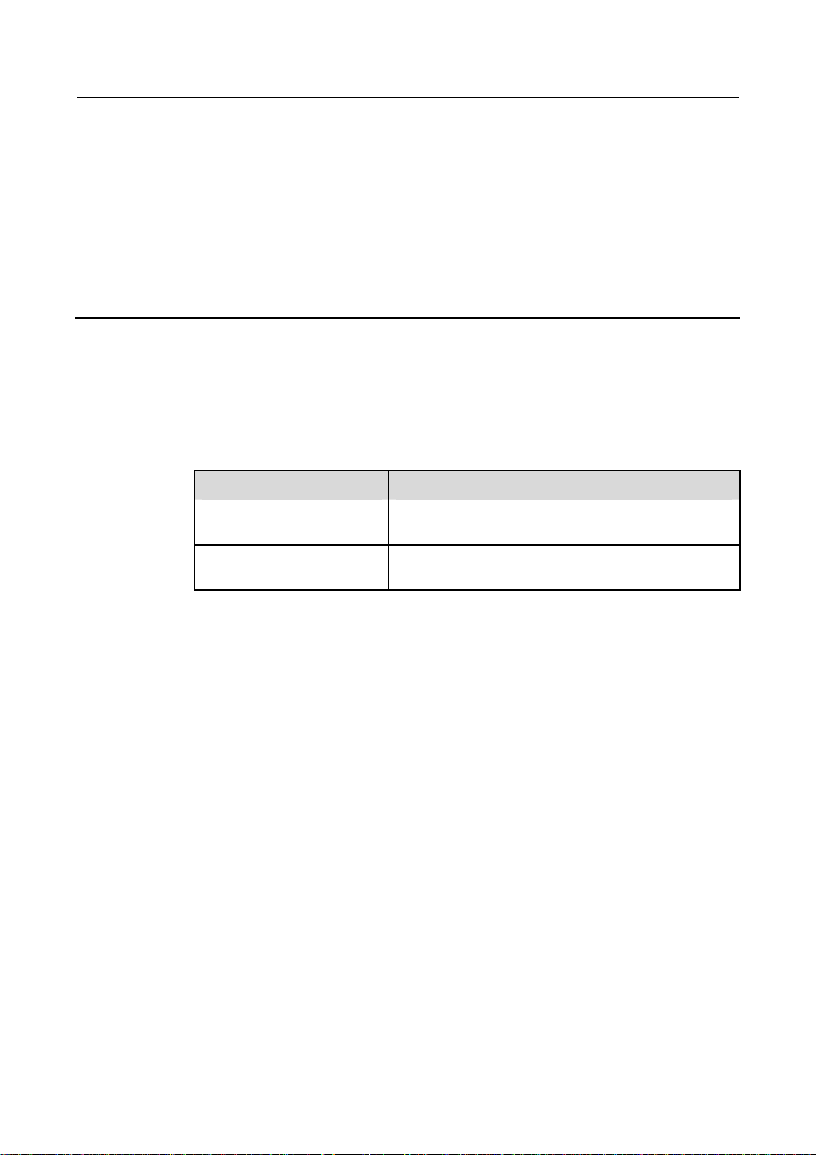
The following table lists the contents of this chapter.
Title Description
1.1 BTS Equipment Describes the BTS equipment to be verified before
1.2 Tools for Commissioning Describes the tools involved in commissioning.
1.3 Personnel Describes the personnel required for commissioning.
1.4 Site Information Describes the site information to be collected before
1.5 Data Configuration Files Described the requirements for data configuration files.
Commissioning Preparations
commissioning.
commissioning.
Issue 02 (2006-10-10) Huawei Technologies Proprietary 1-1
Page 8

1 Commissioning Preparations
1.1 BTS Equipment
Before commissioning, ensure that:
z
The cabinet and its components are installed correctly.
z
The antenna system is installed and connected.
z
The transmission equipment is connected.
z
The BTS O&M software and operational software are installed.
z
The power system is installed.
z
The equipment for monitoring the equipment room environment is installed. (optional)
1.2 Tools for Commissioning
Table 1-1 lists the tools for BTS commissioning.
Airbridge BTS3606E&3606AE
System Commissioning Guide
Table 1-1 Tools for BTS commissioning
Tool Quantity Remark
CDMA MS Two Mandatory
Qualcomm CAIT or a BLUEROSE One Mandatory
RS NRT-Z44 power meter One Optional
SiteMaster 331A One Mandatory
30 dB low-power coaxial attenuator One Optional
20 dB low-power coaxial attenuator Two Optional
DIN-male to N-female adapter One Optional
1.3 Personnel
Huawei technical support engineers and the engineers representing the customers complete
the system commissioning together. The customer representative should sign the acceptance
list after the commissioning is complete.
1.4 Site Information
To facilitate the preparation of commissioning tools and commissioning schemes, collect the
following basic information before you start the commissioning of the BTS:
z
BTS ID
1-2 Huawei Technologies Proprietary Issue 02 (2006-10-10)
Page 9

Airbridge BTS3606E&3606AE
System Commissioning Guide 1 Commissioning Preparations
z
IP address for O&M
z
PN code
z
Service type
1.5 Data Configuration Files
After making the data configuration files, the system commissioning personnel copies them
into the workstation (WS). The system commissioning personnel must ensure that each data
configuration file is named in the format of BTSXXX.txt.
The names of the configuration files are in the format of BTSXXX.txt. "XXX" stands for the BTS ID.
This part must be three digits long. If the BTS ID has fewer than three digits, zeroes are added on the
ID’s left to make up three digits.
The commissioning personnel can check the configuration data in the files and the site
information. Pay special attention to the data of the Abis interfaces.
Issue 02 (2006-10-10) Huawei Technologies Proprietary 1-3
Page 10

Page 11
Airbridge BTS3606E&3606AE
System Commissioning Guide 2 Commissioning Modes
About This Chapter
The following table lists the contents of this chapter.
Title Description
2.1 Local Commissioning Describes typical operation tasks and classification of the
2.2 Remote Commissioning Describes typical operation tasks and classification of the
2
BTS local commissioning.
BTS remote commissioning.
Commissioning Modes
Issue 02 (2006-10-10) Huawei Technologies Proprietary 2-1
Page 12

2 Commissioning Modes
2.1 Local Commissioning
The local commissioning is performed at the BTS site for the commissioning of the
BTS3606E/3606AE or for the commissioning of the BSS. For the latter purpose, the
coordination of the BSC is required.
The local commissioning includes local commissioning in Telnet mode and reverse
maintenance.
2.1.1 Local Commissioning in Telnet Mode
In the case of local commissioning in Telnet mode, you can connect the WS to the BCKM by
using a crossover Ethernet cable and then log in to the BTS. In this mode, you can use
commands to perform BTS commissioning.
2.1.2 Reverse Maintenance
In the case of reverse maintenance, you can connect a BSC LMT to the BCKM by using a
crossover Ethernet cable and then use this LMT to log in to the BAM of the BSC. In reverse
maintenance mode, you can maintain the entire BSS system from a BTS site.
Airbridge BTS3606E&3606AE
System Commissioning Guide
2.1.3 Local Commissioning Tasks
The operation tasks related to the local commissioning are as follows:
z
Configuring the WS
z
Locally Logging In to the BTS in Telnet Mode
z
Configuring the IP Address and Routing Information of the BTS
z
Loading the BTS Software Locally
z
Performing the BSS Reverse Maintenance
z
O&M Test
z
RF Performance Test
z
Service Function Test
For detailed steps of each operation task, see 3.3 "Starting Local Maintenance"
2.2 Remote Commissioning
By using maintenance tools, you can commission the entire BSS system remotely with the
coordination of the BSC.
The remote commissioning includes the remote commissioning on LMT system and the
remote commissioning in Telnet mode.
2.2.1 Remote Commissiong on the LMT System
In the case of the remote commissioning on the LMT, you can input a command for
commissioning on the LMT. This command is processed by the BAM server and is then sent
to the BTS for response. The BAM server records the operation results, such as successful,
2-2 Huawei Technologies Proprietary Issue 02 (2006-10-10)
Page 13

Airbridge BTS3606E&3606AE
System Commissioning Guide 2 Commissioning Modes
failed, timeout, and abnormal, and then sends the result to the LMT. In such a case, you can
know the operation result.
2.2.2 Remote Commissioning in Telnet Mode
In the case of remote commissioning in Telnet mode, you can log in to the BTS by using
Telnet software. The commissioning for the BTS3606E/3606AE is performed with the
coordination of the BSC.
2.2.3 Remote Commissioning Tasks
The operation tasks related to the remote commissioning are as follows:
z
Configuring the WS
z
Starting the LMT
z
Remotely Logging In to the BTS in Telnet Mode
z
Loading the BTS Software Remotely
z
O&M Test
z
RF Performance Test
z
Service Function Test
For detailed steps of each operation task, see 3.3 "Starting Local Maintenance".
Issue 02 (2006-10-10) Huawei Technologies Proprietary 2-3
Page 14

Page 15

Airbridge BTS3606E&3606AE
System Commissioning Guide 3 Commissioning Process
About This Chapter
The following table lists the contents of this chapter.
Title Description
3.1 Commissioning Flowchart Describes the BTS commissioning process and
3.2 BTS Startup Process Describes the general procedure for starting the BTS.
3.3 Starting Local Maintenance Describes the procedure for starting local
3.5 O&M Test Describes the procedure of O&M commissioning.
3.6 RF Performance Test Describes the procedure of the commissioning of the
3
Commissioning Process
operation tasks in terms of flowchart.
maintenance.
RF specifications.
3.6 Service Function Test Describes the procedure of service function
commissioning
Issue 02 (2006-10-10) Huawei Technologies Proprietary 3-1
Page 16

3 Commissioning Process
3.1 Commissioning Flowchart
Figure 3-1 shows the flowchart for BTS commissioning.
Figure 3-1 BTS system commissioning flowchart
Airbridge BTS3606E&3606AE
System Commissioning Guide
Start
Configuring the WS
Logging In to the BTS in
Telnet Mode
Configuring the IP
Address and Routeing
Information of the BTS
Starting the LMT
Logging In to the BTS
Remotely in Telnet Mode
Performing the BSS
Reverse Maintenance
Loading the BTS Software
Locally
Loading the BTS Software
Remotely
Location Update Test
BTS Coverage Test
BTS Startup Process
Starting Local
Maintenance
O&M Test
RF Performance Test
Querying Basic Information of t he
BTS
Querying BTS Board Version
Verifying the Software Version
Querying Availability of BTS Cells
Active Alarms of the BTS Querying
Querying the Configuration Data of
the BTS
Verifying the Consistency Between
the BTS and the Configuration
Data of the BSC Interface
Querying the Status of the BTS
Links
Forward Power Test
Reverse RSSI Test
MS Call Test
Handoff Test
Short Message Service
Test
Mobile-Originated Packet
Data Call Test
Mobile-Terminated Packet
Data Call Test
Service Function Test
End
3-2 Huawei Technologies Proprietary Issue 02 (2006-10-10)
Page 17

Airbridge BTS3606E&3606AE
System Commissioning Guide 3 Commissioning Process
3.2 BTS Startup Process
This section describes the process of the BTS startup.
3.2.1 BTS Startup Flowchart
Figure 3-2 shows the flowchart for BTS startup.
Figure 3-2 BTS startup flowchart
Start
Initialize boards
Set up OML
Download and activate
configuration files
Set up signaling links
Set cell information
Search for satellites
Set up traffic links
End
Issue 02 (2006-10-10) Huawei Technologies Proprietary 3-3
Page 18

3 Commissioning Process
z
For the descriptions of board indicators or module indicators, see the
Base Station Hardware Reference or the Airbridge BTS3606AE CDMA Base Station Hardware
Reference.
z
For the detailed information of BTS alarms, see the online help and the
BTS3606E&3606AE CDMA Base Station Site Maintenance Guide
of the alarm management system.
z
For the troubleshooting related to BTS startup, see the
Station Site Maintenance Guide
Airbridge BTS3606E&3606AE CDMA Base
.
3.2.2 Description of the BTS Startup Process
This section details the steps shown in Figure 3-2.
Board Initialization
After the BTS is powered on, the BOOT software of each board transfers the board software
from the Flash memory to the RAM. After the board self-test and initialization, the
communication link between the boards is set up.
If the board initialization fails, the board resets.
Airbridge BTS3606E&3606AE
System Commissioning Guide
Airbridge BTS3606E CDMA
Airbridge
or the detailed alarm description
Table 3-1 describes the symptom of board initialization.
Table 3-1 Symptom of board initialization
Observation
Method
Through indicators
of the BTS
On the service
maintenance system
Setting Up the OML
After the self-test, the baseband boards set up the OML with the BSC. Setting up the OML
from the BTS to the BSC is the prerequisite for configuring the BTS at the far end.
Description
During the power-on and initialization process of the BCKM and
the BCIM, the RUN indicator flashes fast at 4 Hz.
Before the operation and maintenance link (OML) is set up, the
ACT indicator on the BCKM flashes fast at 4 Hz.
The frequency at which the ALM indicator flashes varies with the
alarm level.
The BTS is in the link interruption state.
The physical bearer between the BTS and the BSC can be E1/T1 or FE. These bears can be
used to transmit ATM cells and IP packets.
The BTS supports the following three modes for setting up OMLs:
z
Setting up the OML in ATM over E1/T1 mode
z
Setting up the OML in IP over E1/T1 mode
z
Setting up the OML in IP over FE mode
3-4 Huawei Technologies Proprietary Issue 02 (2006-10-10)
Page 19

Airbridge BTS3606E&3606AE
System Commissioning Guide 3 Commissioning Process
z
If the OML cannot be set up during the BTS startup, the BTS restarts five minutes later. If the OML
is interrupted when the BTS is processing services, the BTS sets up the OML repeatedly but the BTS
do not restart.
z
Before querying the status of the CTRM/OMTR, ensure that the status of the CCPM/CECM is
normal.
The following details three modes for setting up OMLs.
The process of setting up the OML in ATM over E1/T1 mode is as follows:
Step 1 When the BTS is started, the BCKM sends a BOOTP request to the CMUX of the BSC.
Step 2 The CMUX writes into the BOOTP frame the information of the transmission channel and
transfers the information to the BAM.
This information is used as the address parameters of the client BTS and is called BOOTP
information.
Step 3 After receiving the BOOTP request, the BAM obtains the BTS ID according to the BOOTP
information (execute the command ADD BTSBTPINFO to map the BTS ID to the BOOTP
information).
Step 4 The BAM obtains the maintenance IP address of the BTS according to the BTS ID (execute
the command ADD BTS to map the BTS ID to the maintenance IP address).
Step 5 The BAM writes the maintenance IP address into the BOOTP response frame and sends the
frame to the BTS.
Step 6 After obtaining the maintenance IP address, the BTS sends a request for setting up a TCP link
to the BAM.
Step 7 The BAM receives this request and sets up the OML from the BTS to the BAM.
----End
In the case of setting up the OML through the E1/T1 link in the IP transmission mode, after
two BOOTP requests, the BTS obtains the IP address of the BCIM, routing information, and
maintenance IP address of the BTS.
For the details of the BOOT requests of the BCKM, see the description of setting up the OML
in ATM over E1/T1 mode in 3.2.2 "Description of the BTS Startup Process."
The process of setting up the OML in IP over E1/T1 mode is as follows:
Step 1 When the BTS is started, the BCIM sends the PPP setup request to the BSC. After obtaining
the PPP IP address, the BTS sets up a PPP connection with the BSC.
Step 2 The BCIM sends a BOOTP request to the CBPE of the BSC.
Step 3 After receiving the BOOTP request, the CBPE obtains the IP address and routing information
of the BCIM from the BOOTP transmission channel.
Step 4 The CBPE writes the maintenance IP address of the BCIM into the BOOTP response frame
and sends it to the BCIM.
Step 5 The BCKM sends the BOOTP request to the BSC and obtains the maintenance IP address of
the BTS.
Step 6 After obtaining the maintenance IP address, the BTS sends a request for setting up a TCP link
to the BAM.
Issue 02 (2006-10-10) Huawei Technologies Proprietary 3-5
Page 20

3 Commissioning Process
Step 7 The BAM receives this request and sets up the OML from the BTS to the BAM.
----End
In the case of setting up the OML in IP over FE mode, the IP address of the BCIM and the
O&M IP address of the BTS cannot be obtained through the BOOTP if the BTS starts for the
first time. You must configure them at the BTS side.
The process of setting up the OML in IP over FE mode is as follows:
Step 1 Execute the command SET CBTSBCIMIP to set the IP address of the BCIM.
Step 2 Execute the command ADD CBTSFEPORT to set the FE port on the BCIM.
Step 3 Execute the command ADD CBTSIPROUTE to set the BTS routing information.
Step 4 Execute the command SET CBTSOAMIP to set an IP address of the BTS O&M.
Step 5 The BTS sends a request for setting up an OML with the BSC.
Step 6 The BAM receives the request and sets up an OML from the BTS to the BSC.
----End
Airbridge BTS3606E&3606AE
System Commissioning Guide
Table 3-2 lists the indicator status during the OML setup.
Table 3-2 Indicator status during the OML setup
Observation Method Description
Through the indicators of
the BTS
On service maintenance
system
After the OML is set up normally, the ACT indicators of the
BCKM and BCIM are ON.
After the OML is set up normally, you can view the running
status of the BCKM and the BCIM on the equipment panel.
Searching Satellites
After being initialized, the BCKM searches the satellite to obtain stable and reliable clock
signals for the BTS. If satellite searching fails, the ACT indicator of the BCKM flashes slowly.
At the same time, the CCPM or the CECM restarts repeatedly. If the standby BCKM is
configured and it can search satellite normally, the standby BCKM switches over to the active
one.
Downloading and Activating Data Configuration Files
The BTS downloads and activates the data configuration files from the BAM first. If the
software version of the board is not consistent with that of the BAM and the switch of
auto-download is on, the BTS downloads the board software automatically.
If the OML setup fails and the data configuration files are saved in the Flash memory of the
BCKM, the BTS directly activates the data configuration files in the Flash memory.
3-6 Huawei Technologies Proprietary Issue 02 (2006-10-10)
Page 21

Airbridge BTS3606E&3606AE
System Commissioning Guide 3 Commissioning Process
Table 3-3 lists the indicator status when the BTS downloads data configuration files.
Table 3-3 Indicator status when the BTS downloads data configuration files
Observation
Method
Through the
indicators of the
BTS
At the service
maintenance system
Observing the
correlated alarm
Setting Up Traffic Links
After the BTS obtains a stable clock signal, the CCPM or the CECM sets up the Abis traffic
link through the BCIM according to the configuration parameter obtained from the operation
& maintenance unit (OMU). Then the CCPM or the CECM exchanges traffic data with the
BSC.
Setting Up Signaling Links
After the configuration, the BCKM sets up the Abis signaling link to communicate with the
BSC through the BCIM according to the configuration parameter obtained from the OMU.
Description
The board resets. After the boards run normally, the ACT indicator
switches on.
After the configuration, you can view the running status of all the
boards on the equipment panel.
The alarm related to link interruption is generated.
When the Abis signaling link is interrupted, the BTS resets automatically 10 minutes later.
Setting Up Cells
After the Abis signaling link is set up, the BCKM reports the BTS resource configuration state
to the BSC and requests logical configuration.
After the BSC sends the cell configuration data to the BCKM, the BTS configures the carrier
properties, sets up the common channel, and updates the overhead message. After that, the
MS is allowed to access the network and make a call.
3.3 Starting Local Maintenance
This section describes the process of starting local maintenance.
3.3.1 Configuring the WS
Task Description
Configure the IP address of the WS which is used for commissioning.
Issue 02 (2006-10-10) Huawei Technologies Proprietary 3-7
Page 22

3 Commissioning Process
Prerequisites
To configure the WS, ensure that:
z
The WS is installed with the Windows operating system.
z
The network adapter of the WS works normally.
Operation Procedure
The WS mentioned in the procedure is installed with Windows XP.
To configure the IP address of the WS, do as follows:
Step 1 Choose Start > Control Panel.
Step 2 Double-click Network Connections.
The Network and Dial-up Connections interface is displayed.
Step 3 Right-click Local Connection and choose Properties.
The Local Connection Properties dialog box is displayed, as shown in Figure 3-3.
Airbridge BTS3606E&3606AE
System Commissioning Guide
Figure 3-3 Local connection properties
3-8 Huawei Technologies Proprietary Issue 02 (2006-10-10)
Page 23

Airbridge BTS3606E&3606AE
System Commissioning Guide 3 Commissioning Process
Step 4 Choose Internet Protocol (TCP/IP) and click Properties.
The Internet Protocol (TCP/IP) Properties dialog box is displayed, as shown in Figure 3-4.
Figure 3-4 Internet protocol (TCP/IP) properties
Step 5 In the General tab, choose Use the following IP address and set the IP address according to
the following requirement.
z
If the WS is used for local commissioning, the IP address must be in the same segment as
the IP address (172.16.16.16 by default) of the local operation and maintenance. The
mask of the subnet must be set to 255.255.0.0. The IP address of the gateway is not set
by default.
Issue 02 (2006-10-10) Huawei Technologies Proprietary 3-9
Page 24

3 Commissioning Process
Figure 3-5 shows the IP address of the WS used for local commissioning.
Figure 3-5 IP address of the WS used for local commissioning
Airbridge BTS3606E&3606AE
System Commissioning Guide
z
If the WS is used for remote commissioning, the IP address is set according to the
requirement of the local network to which the WS belongs.
Step 6 Click OK.
----End
3.3.2 Locally Logging In to the BTS in Telnet Mode
Task Description
Log in to the BTS locally by using the Telnet software.
Prerequisites
To configure the WS, ensure that the WS is in the same TCP/IP network as the BCKM.
Operation Procedure
To log in to the BTS in Telnet mode locally, do as follows:
3-10 Huawei Technologies Proprietary Issue 02 (2006-10-10)
Page 25

Airbridge BTS3606E&3606AE
System Commissioning Guide 3 Commissioning Process
Step 1 Use a crossover Ethernet cable to connect the Ethernet port of the WS and that of the BCKM.
Figure 3-6 shows the connection between the WS and the BCKM.
Figure 3-6 Connection between the WS and the BCKM
Network
port
Crossover
Ethernet cable
BCKM
BTS
Step 2 Click Start > Run.
Step 3 In the Run dialog box, execute the command cmd.
The Command window is displayed.
Step 4 In the Command window, execute the command Ping xxx.xxx.xxx.xxx to verify the
connectivity between the WS and the BTS.
Step 5 If the connection proves to be successful, execute the command Telnet xxx.xxx.xxx.xxx to
log in to the BTS.
The IP address of the BCKM Ethernet port is 172.16.16.16 by default.
If the computer fails to access the BCKM, the possible causes are as follows:
z
The crossover Ethernet cable is faulty.
z
The IP address of the WS is wrong.
----End
3.3.3 Configuring the IP Address and Routing Information of the
BTS
You need to carry out this task only when the BTS uses an FE link to bear the IP connection and when
the BTS is started for the first time.
Task Description
Configure the IP address and routing information of the BTS that uses IP over FE
transmission.
Prerequisites
z
The WS is in the same TCP/IP network as the BCKM.
z
The communication between the WS and the BCKM is normal.
Issue 02 (2006-10-10) Huawei Technologies Proprietary 3-11
Page 26

3 Commissioning Process
z
The BTS is configured with the QC54BCIM.
Operation Procedure
To configure the IP address and routing information of the BTS locally, do as follows:
Step 1 Log in to the BTS locally. See 3.3.2 "Locally Logging In to the BTS in Telnet Mode" for
details.
Step 2 Set the IP address of the BCIM by executing the command SET CBTSBCIMIP.
Step 3 Set the IP address of the FE port of the BCIM by executing the command ADD
CBTSFEPORT.
Step 4 Set the routing information of the BTS by executing the command ADD CBTSIPROUTE.
Step 5 Set the IP address of the BTS O&M by executing the command SET CBTSOAMIP.
----End
3.3.4 Starting the LMT
Airbridge BTS3606E&3606AE
System Commissioning Guide
This section describes how to start the LMT.
Task Description
Log in to the BAM through the LMT.
Prerequisites
Before starting the LMT, ensure that:
z
The BAM server is operational.
z
The LMT is installed with the O&M software.
z
The network connection between the LMT and the BAM is normal.
z
The user name, password, and related authorities of the WS have been defined in the
BAM.
Operation Procedure
To start the LMT, do as follows:
Step 1 Select Start > All Programs > iManager M2000 > LocalWS.
The Local NE Management System dialog box is displayed.
Step 2 Click Configure to add the IP address of the BAM.
Step 3 Select the BAM to be logged in to and click OK.
The system starts the service maintenance system automatically and the User Login dialog
box is displayed.
Step 4 Type in the valid user name and password, as shown in Figure 3-7.
3-12 Huawei Technologies Proprietary Issue 02 (2006-10-10)
Page 27

Airbridge BTS3606E&3606AE
System Commissioning Guide 3 Commissioning Process
Figure 3-7 User login dialog box
Step 5 Click OK.
If the login fails, the system reports the login failure.
----End
3.3.5 Remotely Logging In to the BTS in Telnet Mode
Task Description
Log in to a BTS remotely in Telnet mode.
Prerequisites
Before logging in to the BTS remotely in Telnet mode, ensure that:
z
The WS and the BAM are in the same TCP/IP network.
z
The communication between the WS and the BAM is normal.
Operation Procedure
The Telnet software mentioned in this procedure is based on Windows XP system. The operation
procedure is different if the Telnet software is based on other operating systems.
To log in to the BTS remotely in Telnet mode, do as follows:
Issue 02 (2006-10-10) Huawei Technologies Proprietary 3-13
Page 28

3 Commissioning Process
Step 1 On the service maintenance system, execute the command STR BTSTELPROXY to start the
Telnet proxy for the BTS to be maintained.
The duration of the Telnet proxy is defined in this step. If this duration expires, the Telnet proxy stops.
Step 2 In the Run dialog box, execute the command Telnet hostname port to connect to the BCKM.
The Telnet window is displayed.
The
Step 3 After the BCKM is connected, log in to the BTS by using the following user name and
password:
z
z
Step 4 After successful login, execute the command opnday to enable predictive text input for
commands and execute commands in the Telnet window to maintain the BTS.
Step 5 Close the Telnet window.
hostname
is the IP address of the BAM. The
User name: system
Initial password: system
Airbridge BTS3606E&3606AE
System Commissioning Guide
port
is the port number set in the first step.
Step 6 On the service maintenance system, execute the command STP BTSTELPROXY to stop the
Telnet proxy.
----End
3.3.6 Performing the BSS Reverse Maintenance
Task Description
By using the reverse maintenance function, you can maintain the entire BSS system at the
BTS side.
Prerequisites
Before performing the BSS reverse maintenance, ensure that:
z
The WS and the BAM are in the same TCP/IP network.
z
The communication between the WS and the BAM is normal.
z
The OML between the BTS and the BAM is set up.
3-14 Huawei Technologies Proprietary Issue 02 (2006-10-10)
Page 29

Airbridge BTS3606E&3606AE
System Commissioning Guide 3 Commissioning Process
z
To connect the WS and the BCKM, connect a crossover Ethernet cable to the Ethernet
ports on the WS and the BCKM. The IP address of the WS and that of the BCKM Ethernet
interface must be in the same network segment.
z
By default, the IP address of the BCKM Ethernet interface is 172.16.16.16 and the mask is
255.255.0.0.
Procedure Description
To perform the BSS reverse maintenance, do as follows:
Step 1 Execute the command STR CBTSRVSMNT to start the reverse maintenance function.
Step 2 At the WS of the BAM side, add the WS and set the command authority for the WS of the
BCKM side by using the LMT.
When adding the WS, you must set the parameter
IP address
to the IP address of the BTS maintenance.
Step 3 At the WS of the BCKM side, run the local NE management system or independent LMT
software to log in to the BTS.
For the login to the BTS, the IP address of the BAM must be the IP address (172.16.16.16) of the
BCKM Ethernet port rather than the real IP address of the BAM.
Step 4 Use the LMT software to maintain the BSS system.
Step 5 Execute the command STP CBTSRVSMNT to stop the inverse maintenance function.
Step 6 Exit the LMT software.
----End
3.3.7 Loading the BTS Software Locally
Task Description
Load the configuration files and board software into the BTS from the WS connected with the
BCKM.
Prerequisites
Before loading the BTS software locally, ensure that:
z
The IP address of the WS and the IP address of the BCKM are in the same network
segment.
z
The Ethernet port of the WS and that of the BCKM is connected by crossover Ethernet
cables.
Issue 02 (2006-10-10) Huawei Technologies Proprietary 3-15
Page 30

3 Commissioning Process
z
The loading of the BTS software does not affect the service.
z
The service is affected if you activate the BTS software.
z
When using the FTP to load software, you can load only one software module by
executing one command.
Operation Procedure
Step 1 Execute the command FTP ipaddress to log in to the BTS by using the following user name
and password:
z
User name: system
z
Initial password: system
Step 2 Execute the command PUT File.Path File.Name to download the specified software to the
BTS.
To load fil e bckm3606.bzp stored in drive D, execute the command PUT D:\bckm3606.bzp.
Airbridge BTS3606E&3606AE
System Commissioning Guide
Step 3 After the loading is successful, execute the command LI ACT Boardname.Type to activate
the specified software.
To activate the CPU software of the BCKM, execute the command LI ACT bckm.cpu.
You can obtain the help information by executing the command
LI ACT?.
z
The loading sequence is: CMTR/OMTR→CCPM/CECM→BCIM→BCKM.
z
For the loading of each board, you must load the FPGA before loading the CPU software.
z
To minimize the impact on service provision, you can load all the BTS software and then
activate the software in order when the traffic is low.
Step 4 Execute the command DSP CBTSBRDVER to check whether the activation is successful.
Step 5 If the activation is successful, repeat the steps 2 and 3 to activate all the BTS software.
----End
3-16 Huawei Technologies Proprietary Issue 02 (2006-10-10)
Page 31

Airbridge BTS3606E&3606AE
System Commissioning Guide 3 Commissioning Process
3.3.8 Loading the BTS Software Remotely
Task Description
Load the configuration files and BTS running software into the BTS from the LMT.
Prerequisites
Before starting the LMT, ensure that:
z
The BAM server is operational.
z
The WS is installed with the LMT software.
z
The communication between the WS and the BAM is normal.
Operation Procedure
Step 1 Put the configuration files and BTS running software to the following directories:
z
Configuration files: \cdma2000\BTSLoad\cfg (by default)
z
BTS software: \cdma2000\BTSLoad\BTS3606 (by default)
Step 2 Log in to the BAM by using the LMT.
For details, see 3.3.4 "Starting the LMT."
Step 3 Execute the following commands to load BTS software.
z
Execute the command DLD CBTSSW to load only or load and activate the specified
BTS running software or configuration files.
z
Execute the command DLD CBTSALLSW to load only or load and activate all the
running software or configuration files of the specified BTS.
z
The loading of the BTS software does not affect the service.
z
The service is affected if you activate the BTS software.
Step 4 After the loading is successful, exit the LMT.
----End
Issue 02 (2006-10-10) Huawei Technologies Proprietary 3-17
Page 32

3 Commissioning Process
3.4 O&M Test
Unless otherwise specified, carry out the following tasks at the BAM side.
Before the O&M test, ensure that the CCPM/CECM and the CMTR/OMTR works normally.
3.4.1 Querying Basic Information of the BTS
To query the basic information of the BTS, do as follows:
Step 1 Enter the following command:
LST BSCBTSINF
Airbridge BTS3606E&3606AE
System Commissioning Guide
Step 2 Click
Step 3 Specify the values of the parameters.
For example: LST BSCBTSINF: BTSID=1;
Step 4 Click
----End
or press Enter.
or press F9 to execute the command.
3.4.2 Querying BTS Board Version
To query the BTS board version, do as follows:
Step 1 Enter the following command:
DSP CBTSBRDVER
Step 2 Click
Step 3 Specify the values of the parameters.
For example: DSP CBTSBRDVER: BTSNAME="BTS", BTSID=1, BRDTP=BCKM,
BRDID=0;
Step 4 Click
or press Enter.
or press F9 to execute the command.
----End
3.4.3 Verifying the Software Version
The command
software version of the BTS boards and the BAM version.
To verify the software version, do as follows:
3-18 Huawei Technologies Proprietary Issue 02 (2006-10-10)
CHK CBTSSWVER
is used only for verifying the consistency between the running
Page 33

Airbridge BTS3606E&3606AE
System Commissioning Guide 3 Commissioning Process
Step 1 Enter the following command:
CHK CBTSSWVER
Step 2 Click
Step 3 Specify the values of the parameters.
For example: CHK CBTSSWVER: BTSID=1;
For the detailed explanation of the parameters, see the online help.
Step 4 Click
----End
or press Enter.
or press F9 to execute the command.
3.4.4 Querying Availability of BTS Cells
To query the availability of BTS cells, do as follows:
Step 1 Enter the command DSP RES.
Step 2 Click
Step 3 Specify the values of the parameters. For detailed explanation of the parameters, see the
online help.
For example: DSP RES:;
Step 4 Click
or press Enter.
or press F9 to execute the command.
----End
3.4.5 Querying Active Alarms of the BTS
To query the active alarms of the BTS, do as follows:
Step 1 Enter the command LST ALMFE.
Step 2 Click
Step 3 Specify the values of the parameters.
For detailed explanation of the parameters, see the online help.
For example: LST ALMFE: CNT=20; (CNT is the returned record number.)
Step 4 Click
----End
or press Enter.
or press F9 to execute the command.
3.4.6 Querying the Configuration Data of the BTS
To query the configuration data of the BTS, do as follows:
Step 1 Execute the command DSP CBTSCFG to query the configuration data of the BTS.
Step 2 Click
Issue 02 (2006-10-10) Huawei Technologies Proprietary 3-19
or press Enter.
Page 34

3 Commissioning Process
Step 3 Specify the values of the parameters.
For detailed explanation of the parameters, see the online help.
For example: DSP CBTSCFG : BTSNAME="BTS", BTSID=1, CFGID=CBTSINFO;
Airbridge BTS3606E&3606AE
System Commissioning Guide
Step 4 Click
----End
or press F9 to execute the command.
3.4.7 Verifying the Consistency of the Configuration Data
Between the BTS and the BSC Interface
To verify the consistency of the configuration data between the BTS and the BSC interface,
do as follows:
Step 1 Enter the command CHK CBTSIFCFG.
Step 2 Click
Step 3 Specify the values of the parameters.
For detailed explanation of the parameters, see the online help.
For example: CHK CBTSIFCFG: BTSID=1, CFGINFO=ALL;
Step 4 Click
----End
or press Enter.
or press F9 to execute the command.
3.4.8 Querying the Status of the BTS Links
To query the status of the BTS links, do as follows:
Step 1 Enter the command DSP CBTSLNKSTAT.
Step 2 Click
Step 3 Specify the values of the parameters.
For detailed explanation of the parameters, see the online help.
For example: DSP CBTSLNKSTAT: BTSID=1, BRDID=0;
Step 4 Click
----End
or press Enter.
or press F9 to execute the command.
3.5 RF Performance Test
The RF performance test consists of:
z
Forward power test
z
Reverse RSSI test
3-20 Huawei Technologies Proprietary Issue 02 (2006-10-10)
Page 35

Airbridge BTS3606E&3606AE
System Commissioning Guide 3 Commissioning Process
When the BTS3606E/BTS3606AE uses the multi-carrier transceiver, the CMTR/OMTR and
CMPA/OMPA need about five minutes to perform self adaptation after software loading.
During this period, the index of transmit signals cannot satisfy the rated requirement and the
adjacent channels are affected.
3.5.1 Forward Power Test
This section describes how to conduct a forward power test. It also describes the precautions
you must take before conducting a forward power test.
Precautions
Pay attention to the following points when conducting a forward power test:
z
The fan box must be installed to ensure the normal operation of the power amplifier.
z
Power unit is 0.1 dBm.
z
Ensure that the coupling port without the connection lines is connected to a matching
load to avoid generating internal interference and external radiation.
z
Consider RF cable loss (it is related to the texture and thickness of the RF cable) when
analyzing the test result. In general, the loss of one-meter cable is 0.5 dB, and that of
two-meter cable is 1 dB.
z
Before the power test, stop all services. The TRM restarts after the test is complete.
z
Connect the power meter to the TX/RX-TEST port using an RF coaxial cable and then
perform the power test.
z
Take the cable loss and the coupling degree of the TX/RXM-TEST port into account.
The coupling degree of the TX/RX-TEST port is available in the model information of
this port. It is generally 30 dB.
z
If a high-precision power meter is used, carry out the test on the antenna port and test
port. If a low-precision power meter is used, carry out the test on the antenna port.
Test Procedure
The test procedure is as follows:
Step 1 Connect the cables.
Figure 3-8 shows the connection for forward power test when configuring a CDDU.
Issue 02 (2006-10-10) Huawei Technologies Proprietary 3-21
Page 36

3 Commissioning Process
Figure 3-8 Connection for forward power test
Airbridge BTS3606E&3606AE
System Commissioning Guide
TX2/RX2-ANT
TX2/RX2
CDDU
TX1/RX1-ANT
TX1/RX1 - TEST
BTS
cabinet top
Power
meter
TEST
-
Antenna
Step 2 In the Windows operating system of the LMT, select Start > Run, type Telnet
xxx.xxx.xxx.xxx in the Run dialog box, and then press Enter to start Telnet.
For the near end Telnet, the default IP address of the Ethernet port is 172.16.16.16.
Step 3 Start the power test for the BTS transmitting at full power.
For example, for the 450A carrier, execute the following commands:
HW CBTS>str trmpowertst:brdid=2,chid=0,channo=210
Are you sure?(Y or N)y
Ok
HW CBTS>str trmpowertst:brdid=2,chid=1,channo=160
Are you sure?(Y or N)y
Ok
HW CBTS>str trmpowertst:brdid=2,chid=2,channo=260
Are you sure?(Y or N)y
Ok
z
"chid" is the ID of a carrier provided by the TRM. The IDs of the carriers provided by the
CMTR/OMTR are 0, 1, and 2.
z
"channo" is the center frequency of the carrier.
z
You must test the powers of the three carriers of the CMTR/OMTR at the same time.
Step 4 After preheating the BTS for ten minutes, check the output power that is displayed on the
power meter and record the value.
Step 5 Analyze the test result.
See section 3.5.2 "Forward Power Test Analysis."
If the result is abnormal, handle the situation according to section 3.5.2 "Forward Power Test
Analysis."
3-22 Huawei Technologies Proprietary Issue 02 (2006-10-10)
Page 37

Airbridge BTS3606E&3606AE
System Commissioning Guide 3 Commissioning Process
Step 6 If the result is normal, conduct forward power interface tracing and compare the test result
with the power test result.
For example, to trace the CMTR or OMTR configured in slot 2, execute the following
commands:
HW CBTS>str infotrace
<(brdtp=?bckm_omu/bckm_sig/bckm_clk/bcim/ccpm/trm), mandatory >trm
<(brdid=?),mandatory >2
<(item=?),optional>"power"
ok
Step 7 Stop forward power interface tracing.
For example, to stop tracing the CMTR or OMTR configured in slot 2, execute the following
commands:
HW CBTS>stp infotrace
<(brdtp=?bckm_omu/bckm_sig/bckm_clk/bcim/ccpm/trm), mandatory >trm
<(brdid=?),mandatory >2
<(item=?),optional>"power"
ok
Step 8 Repeat steps 1 to 5 to test other CMTRs or OMTRs.
Step 9 Stop the power test as follows:
HW CBTS>stp trmpowertst
<(brdid=?),mandatory >2
<(chid=?),mandatory >1
ok
----End
3.5.2 Forward Power Test Analysis
This section provides the parameters and analysis of forward power test results.
Troubleshooting methods are also provided for abnormal test results.
Parameter Description
Table 3-4 describes the parameters associated with the forward power test.
Table 3-4 Parameter associated with the forward power test
Parameter Description
Base band power Set by the CSM5000 or CSM5500 of the CCPM or CECM
Digital power Digital power
Attenuation Attenuation
Digital power sum Sum of digital power
HPA Output power Output power of the high power amplifier
HPA Input power Input power of the high power amplifier
Issue 02 (2006-10-10) Huawei Technologies Proprietary 3-23
Page 38

3 Commissioning Process
Parameter Description
Obs chan power Channel power in the feedback
Obs gain adjust Gain adjustment in the feedback
Obs gain Identical Channel gain identical adjustment in the feedback
IF gain adjust Adjustment of the intermediate frequency gain
RF gain adjust Adjustment of the radio frequency gain
DDU gain adjust Adjustment of the DDU gain
PD RMS Error Adjust value of pre-distortion
DAC Input Power Power before conversion
RF Forward Power The power of the RF signal output port
Example of Test Result
Airbridge BTS3606E&3606AE
System Commissioning Guide
This example shows the full power output of the BTS3606E or BTS3606AE when the CMTR
or OMTR is used to provide three carriers.
TRM2:
Base band power: carrier0 = ***, carrier1 = ***, carrier2 = ***
Digital power : carrier0 = ***, carrier1 = ***, carrier2 = ***
Attenuation : carrier0 = ***, carrier1 = ***, carrier2 = ***
Digital power sum = ***., HPA Output power = ***, HPA Input power = ***
Obs chan power = ***, Obs gain adjust = ***, Obs gain Identical = ***
IF gain adjust = ***, RF gain adjust = ***, DDU gain adjust = ***
PD RMS Error = ***, DAC Input Power = ***, RF Forward Power = ***
Analysis of Test Result
The analysis of the test result is described as follows:
z
The normal output power (Digital power) for a carrier is 43 dBm ! 1 dB (that is, 20 W !
1 dB).
z
If the test result displayed on the power meter is out of normal range, compare it with the
result of interface tracing.
Troubleshooting
Some common troubleshooting methods are as follows:
z
If the test result displayed on the power meter is out of normal range, start interface
tracing to check the values of the parameters Base band power, Digital power, and
HPA Output power.
z
In theory, if the value of the parameter Base band power is not normal, the values of
Digital power and HPA Output power are also not normal. In such a case, check if the
BTS gain is set correctly. If BTS gain is correct, analyze the CCPM performance and
CECM performance by querying BTS configuration and checking the
CSM5000/CSM5500/CSM6800.
3-24 Huawei Technologies Proprietary Issue 02 (2006-10-10)
Page 39

Airbridge BTS3606E&3606AE
System Commissioning Guide 3 Commissioning Process
z
If Base band power is normal, but Digital power is not normal, the values of HPA
Output power must be not normal in theory. In such a case, check the CMTR or OMTR
to locate the fault. For example, insert and remove it, or replace it.
z
If only HPA Output power is not normal, check the installation of CMPA or OMPA and
its connection with the CMTR or OMTR.
z
If all the parameter values reported in the interface tracing are normal, do as follows:
−
Check the connections between the CMPA/OMPA and the CDDU/IDFU/ODFU.
−
Check the antenna system and ports on the top of the cabinet for errors.
3.5.3 Reverse RSSI Test
The RSSI test includes the local RSSI test and the remote RSSI test.
In the case of the remote RSSI test, you can perform the reverse RSSI test by:
z
Selecting Resource Monitoring > RSSI Monitoring, or
z
Logging in to the BTS in Telnet mode.
In the case of local RSSI test, you can connect the WS to the BCKM by using a crossover
Ethernet cable and then log in to the BTS in Telnet mode. In this mode, you can use
commands to perform BTS commissioning.
Precautions
Test Procedure
Step 1 Connect the cables as shown in Figure 3-9.
This section describes how to conduct reverse RSSI tests in the local RSSI test. It also
describes the precautions you must take when conducting the tests.
Note the following points before conducting the forward power test:
z
You can choose not to install RF fans; however, to ensure zero transmission power, you
have to connect the antenna with the CDDU/CDFU.
z
The unit for the average and peak values of RSSI is 0.1 dBm.
z
Check whether the coupling port without connection lines is connected to a matching
load to avoid generating internal interference and external radiation.
The test procedure is as follows:
Figure 3-9 Connection for reverse RSSI test of the BTS
Network
port
BCKM
BTS
Crossover cable
Issue 02 (2006-10-10) Huawei Technologies Proprietary 3-25
Page 40

3 Commissioning Process
Step 2 In the Windows operating system of the LMT, select Start > Run.
Step 3 In the Run dialog box, type in Telnet xxx.xxx.xxx.xxx, and then press Enter to run the
Telnet program.
Step 4 Check the BTS configuration, and ensure that the data configuration complies with the actual
cable connection of the RF subrack.
Step 5 Start reverse RSSI test.
For example, to trace the CMTR or OMTR configured in slot 1, execute the following
commands:
HW CBTS>str infotrace
<(brdtp=?bckm_omu/bckm_sig/bckm_clk/bcim/ccpm/trm), mandatory >trm
<(brdid=?),mandatory >1
<(item=?),optional>"rssi"
Ok
Step 6 Record test results.
Step 7 Stop the reverse RSSI test as follows:
HW CBTS>stp infotrace
<(brdtp=?bckm_omu/bckm_sig/bckm_clk/bcim/ccpm/trm), mandatory >trm
<(brdid=?),mandatory >1
<(item=?),optional>"rssi"
Ok
Airbridge BTS3606E&3606AE
System Commissioning Guide
You can also stop the RSSI test by restarting the Telnet program.
----End
3.5.4 Reverse RSSI Test Analysis
This section provides the parameters, examples, and analysis of reverse RSSI test results.
Troubleshooting methods for abnormal test results are also provided.
Parameter Description
Table 3-5 describes the parameters associated with the reverse RSSI test.
Table 3-5 Parameters associated with the reverse RSSI test
Parameter Description
Main Avg Main RSSI average value
Main Peak Main RSSI peak
Main Ratio The main ratio is more than the main RSSI average value
Divs Avg Diversity RSSI average value
Divs Peak Diversity RSSI peak
Divs Ratio Diversity ratio is larger than average value
3-26 Huawei Technologies Proprietary Issue 02 (2006-10-10)
Page 41

Airbridge BTS3606E&3606AE
System Commissioning Guide 3 Commissioning Process
Parameter Description
Revs pwr Reverse power
RF AGC gain AGC gain of radio frequency
Example of Test Result
The following shows the RSSI value of the CMTR or OMTR configured in slot 2:
HW CBTS>str infotrace : brdtp=trm,brdid=2,item="rssi"
Ok
Carrier0 RSSI: Main Avg = -115.5, Main Peak = -114.3, Main Ratio = 0%
Carrier0 RSSI: Divs Avg = -109.8, Divs Peak = -108.7, Divs Ratio = 0%
Carrier1 RSSI: Main Avg = -115.9, Main Peak = -114.4, Main Ratio = 0%
Carrier1 RSSI: Divs Avg = -109.8, Divs Peak = -108.8, Divs Ratio = 0%
Carrier2 RSSI: Main Avg = -116.4, Main Peak = -114.4, Main Ratio = 0%
Carrier2 RSSI: Divs Avg = -109.8, Divs Peak = -108.8 Divs Ratio = 0%
Revs pwr: Main = -83.3, Divs = -97.1; RF AGC gain: Main = 0.0, Divs = 0.0
Analysis of Test Result
z
If the main RSSI average value (Main Avg) ranges from –100.0 dBm to –108.0 dBm, the
main receive channel is normal.
z
If the diversity RSSI average value (Divs Avg) ranges from –100.0 dBm to –108.0 dBm,
the diversity receive channel is normal.
z
In the case of empty load, the average value of RSSI ranges from –105.0 dBm to –112.0
dBm.
z
The average value difference between the main RSSI and diversity RSSI must be from 2
dB to 3 dB.
Troubleshooting
If the measured RSSI value is too small, check the connections of:
z
Antenna and feeder
z
Ports on top of the cabinet
z
CDDU or IDFU/ODFU
z
RF subrack
If the RSSI value is too large, check if there is an interference source nearby.
3.6 Service Function Test
The service function test help verify BTS services and functions.
They comprise:
z
Location update test
z
BTS coverage test
Issue 02 (2006-10-10) Huawei Technologies Proprietary 3-27
Page 42

3 Commissioning Process
z
MS call test
z
Handoff test
z
Short message service test
z
Mobile-originated packet data call test
z
Mobile-terminated packet data call test
3.6.1 Location Update Test
The test procedure is as follows:
Step 1 Define a test MS in the HLR.
Step 2 Ensure that the network data is correctly configured.
Step 3 Switch on the MS.
Step 4 Start the Abis interface tracing on the BAM by using the LMT.
Step 5 Observe the signaling on the Abis interface and check if either of the following cases occurs:
z
The network side accepts the location update.
z
The network side rejects the location update request.
Airbridge BTS3606E&3606AE
System Commissioning Guide
----End
3.6.2 BTS Coverage Test
The test procedure is as follows:
Step 1 Define a test CDMA MS in the HLR.
Step 2 Select a proper road to carry out a drive test in the BTS coverage area.
Step 3 Record test data, including:
z
Tested BTS
z
Coverage area
z
Sector
z
Distance
z
Signal strength and voice quality
Step 4 Check that the test result conforms to the requirements of engineering design documents.
----End
3.6.3 MS Call Test
The test procedure is as follows:
Step 1 Register two test MSs in the HLR.
Step 2 Power on the two MSs so that they connect to the network and they switch to idle mode.
Step 3 Carry out the following call tests.
z
Make a call from one MS to the other and hook on after the conversation.
3-28 Huawei Technologies Proprietary Issue 02 (2006-10-10)
Page 43

Airbridge BTS3606E&3606AE
System Commissioning Guide 3 Commissioning Process
z
Make a call from one MS to a PSTN subscriber and hook on after the conversation.
z
Make a call from a PSTN subscriber to one MS and hook on after the conversation.
Step 4 Check that all calls are successful.
Step 5 Check that the calls are normal and voice quality is good.
----End
3.6.4 Handoff Test
z
Soft handoff refers to a handoff between different cells operating at the same frequency. Softer
handoff refers to a handoff between different sectors operating at the same frequency and in the
same cell.
z
One cell may contain one or more sectors. This test is relevant when multiple sectors are planned.
The test procedure is as follows:
Step 1 Register two test CDMA MSs in the HLR.
Step 2 Power on the two MSs so that they are attached to the network and they switch to idle mode.
Step 3 Make a call in one sector to set up the conversation between the two MSs.
Step 4 Maintain the call and move one MS to the destination sector.
Step 5 Check that :
z
The call is maintained and stable.
z
Voice quality is good.
----End
3.6.5 Short Message Service Test
Ensure that the network is configured with a message center (MC).
The test procedure is as follows:
Step 1 Register two test MSs in the HLR.
Step 2 Power on the two MSs so that they are attached to the network and they switch to idle mode.
Step 3 Send a short message from MS A to MS B.
Step 4 Check that:
z
MS A displays a prompt that the short message is sent successfully.
z
The message can be queried on the MC.
z
MS B receives the message and displays the messages correctly.
----End
Issue 02 (2006-10-10) Huawei Technologies Proprietary 3-29
Page 44

3 Commissioning Process
3.6.6 Mobile-Originated Packet Data Call Test
Ensure that the system uses dynamic rate allocation.
The test procedure is as follows:
Step 1 Register a test MS in the HLR.
Step 2 Prepare a BlueRose and keep an FTP server ready.
Step 3 Set up a connection between the test MS and the FTP server using the BlueRose and then
initiate an FTP uploading process.
Step 4 Observe the signaling messages and the state transition of the MS on BlueRose.
Step 5 Check the channel setup between the MS and the sector.
z
If the packet data service is unavailable after you log in to the FTP server, infer that the
MS is in dormant mode. If the packet data service is available, infer that the MS is in
active mode.
z
After an FCH is set up, the BTS sends ESCAM messages repeatedly and performs SCH
set-up or SCH extension repeatedly.
Airbridge BTS3606E&3606AE
System Commissioning Guide
----End
3.6.7 Mobile-Terminated Packet Data Call Test
z
Ensure that the system uses dynamic rate allocation.
z
There are various test conditions listed in test steps. You can select some of them and perform the
test according to site conditions.
The test procedure is as follows:
Step 1 Register a test MS in the HLR.
Step 2 Prepare a BlueRose and keep an FTP server ready.
Step 3 Set up a connection between the test MS and the FTP server using the BlueRose and then
initiate an FTP uploading process.
Step 4 Test the downlink rate of a user under the conditions listed in Table 3-6.
Table 3-6 lists the conditions for testing the packet data downlink rate of a user.
Table 3-6 Conditions for testing the packet data downlink rate of a user
No. Status of
Adjacent
Cell
Status of
Destination
Sector
Status of MS Distance from the
MS to the BTS
1 Not loaded Not loaded Static Short
2 Not loaded Not loaded Static Long
3 Not loaded Not loaded Moving at 15 km/h,
Long
30 km/h, and 70 km/h
3-30 Huawei Technologies Proprietary Issue 02 (2006-10-10)
Page 45

Airbridge BTS3606E&3606AE
System Commissioning Guide 3 Commissioning Process
No. Status of
Adjacent
Cell
Status of
Destination
Sector
Status of MS Distance from the
4 100% loaded 50% loaded Static Short
5 100% loaded 50% loaded Static Long
6 100% loaded 50% loaded Moving at 15 km/h,
30 km/h, and 70 km/h
7 100% loaded 50% loaded Moving at 15 km/h,
30 km/h, and 70 km/h
Step 5 Check that the downlink rate of data services is stable.
----End
MS to the BTS
Short
Long
Issue 02 (2006-10-10) Huawei Technologies Proprietary 3-31
Page 46

Page 47

Airbridge BTS3606E&3606AE
System Commissioning Guide 4 Troubleshooting
About This Chapter
The following table lists the contents of this chapter.
Title Description
4.1 Overview of
Troubleshooting
4.2 Board Alarms Describes the types of board alarms and their handing
4.3 Room Environment
Alarms
4
Briefs the troubleshooting during the BTS commissioning.
methods.
Describes the alarms related to the BTS equipment room
environment and their handing methods.
Troubleshooting
Issue 02 (2006-10-10) Huawei Technologies Proprietary 4-1
Page 48

4 Troubleshooting
4.1 Overview of Troubleshooting
The service commissioning includes the commissioning for the BSS, MSC/VLR, HLR, AUC,
and the interfaces with the PSTN and internet. You must locate the fault by specific analysis.
You can know the working status of the BTS by judging:
z
Whether the MS can access to the network.
z
Whether the MS can set up the traffic links.
4.2 Board Alarms
This section describes the types of board alarms and their handing methods.
4.2.1 Alarm Description
The board faults that occur during the operation of BTS are reported to the OMU in the form
of logs and alarms. The OMU records and processes the faults, and then reports them to the
OMC.
Airbridge BTS3606E&3606AE
System Commissioning Guide
The different types of board alarms are as follows:
z
Public alarms such as T8206 related alarm, self-test failure alarm, TTP link alarm, and
temperature alarm
z
BCKM alarms such as software PLL unlocked alarm, clock alarm, and Abis signaling
link interruption alarm
z
CECM/CCPM alarms such as FPGA self-test failure alarm, 50fc PLL unlocked alarm,
CSM5000 chip alarm, and message queue alarm
z
CMTR/OMTR alarms such as PLL unlocked alarm, receive path input overload alarm,
board temperature alarm, forward digital power too high alarm, DAGC alarm, FPGA
alarm, EPLD alarm, RF PLL unlocked alarm, sector VSWR alarm, fan failure alarm,
HPAU alarm, and LNA failure alarm
4.2.2 Alarm Handling
When a fault occurs or when a fault alarm is cleared, the board reports alarm messages to the
OMU. The OMU determines the availability of the board according to the alarm severity.
Table 4-1 describes how to handle different types of board alarms.
Table 4-1 Handling board alarms
To Handle Take the Following Action
Clock alarms or PLL unlocked alarms Check that:
z
Related clock modules and the clock output
are normal.
z
The clock is in the locked state.
4-2 Huawei Technologies Proprietary Issue 02 (2006-10-10)
Page 49

Airbridge BTS3606E&3606AE
System Commissioning Guide 4 Troubleshooting
To Handle Take the Following Action
Power supply alarms, such as high
voltage alarms, low voltage alarms,
power failure alarms, and power fan
failure alarms
Board environment alarms such as
board temperature alarms
Other alarms, such as the alarms caused
by board hardware faults and software
operation errors
4.3 Room Environment Alarms
This section describes the alarms related to the BTS3606E equipment room environment and
their handing methods.
4.3.1 Alarm Description
Check that:
z
The PSU works normally.
z
The mains supply is normal.
Check that:
z
The board is normal.
z
Environmental conditions are normal.
Handle according to the suggestions provided
by the system.
Room environment alarms are collected by an environment alarm chest (EAC) connected
with the BTS3606E. Such alarms include the fire alarm, smoke alarm, access control alarm,
water alarm, temperature alarm, humidity alarm, and air-conditioner alarm.
4.3.2 Alarm Handling
The process for handling an environment alarm is as follows:
Step 1 Upon receiving an environment alarm, the OMU starts the related external devices, such as
air-conditioners, fire extinguishers, smoke removers, and dehumidifiers.
Step 2 The OMU reports alarm messages to the OMC.
Step 3 The OMC displays the alarm on terminals so that maintenance engineers can take actions to
clear the alarms.
----End
Issue 02 (2006-10-10) Huawei Technologies Proprietary 4-3
 Loading...