

Page 1

DBS3900 LampSite
Installation Guide
Issue 07
Date 2015-12-30
HUAWEI TECHNOLOGIES CO., LTD.
Page 2

Copyright © Huawei Technologies Co., Ltd. 2015. All rights reserved.
No part of this document may be reproduced or transmitted in any form or by any means without prior written
consent of Huawei Technologies Co., Ltd.
Trademarks and Permissions
and other Huawei trademarks are trademarks of Huawei Technologies Co., Ltd.
All other trademarks and trade names mentioned in this document are the property of their respective
holders.
Notice
The purchased products, services and features are stipulated by the contract made between Huawei and the
customer. All or part of the products, services and features described in this document may not be within the
purchase scope or the usage scope. Unless otherwise specified in the contract, all statements, information,
and recommendations in this document are provided "AS IS" without warranties, guarantees or
representations of any kind, either express or implied.
The information in this document is subject to change without notice. Every effort has been made in the
preparation of this document to ensure accuracy of the contents, but all statements, information, and
recommendations in this document do not constitute a warranty of any kind, express or implied.
Huawei Technologies Co., Ltd.
Address: Huawei Industrial Base
Bantian, Longgang
Shenzhen 518129
People's Republic of China
Website: http://www.huawei.com
Email: support@huawei.com
Issue 07 (2015-12-30) Huawei Proprietary and Confidential
Copyright © Huawei Technologies Co., Ltd.
i
Page 3
DBS3900 LampSite
Installation Guide
Overview
About This Document
About This Document
This document describes how to install the modules and cables for the BBU, DCU3900,
RHUB3908, pRRU3901, pRRU3902, pRRU3907, and pRRU3911. It also provides checklists
for hardware installation.
NOTE
l Unless otherwise specified, BBU in this document refers to BBU3900 and BBU3910.
l DCU3900 in this document refers to DCU.
l RHUB3908 in this document refers to RHUB.
l Unless otherwise specified, pRRU in this document refers to pRRU3901, pRRU3902, pRRU3907, and
pRRU3911.
Product Version
The following table lists the product version related to this document.
Product Name
DBS3900 LampSite
Intended Audience
This document is intended for:
l BTS installation personnel
Solution Version Product Version
l SRAN10.1 and later versions
l RAN17.1 and later versions
l eRAN8.1 and later versions
l eRAN TDD 8.1 and later
versions
V100R010C10 and later
versions
Issue 07 (2015-12-30) Huawei Proprietary and Confidential
Copyright © Huawei Technologies Co., Ltd.
ii
Page 4

DBS3900 LampSite
Installation Guide Contents
Contents
About This Document.....................................................................................................................ii
1 Changes in DBS3900 LampSite Installation Guide................................................................1
2 Installation Preparations..............................................................................................................5
2.1 Reference Documents.....................................................................................................................................................6
2.2 Preparing Tools and Instruments.................................................................................................................................... 6
2.3 Requirements for Installation Personnel.........................................................................................................................7
3 Unpacking and Checking............................................................................................................ 8
4 Installing a BBU...........................................................................................................................10
5 Installing a DCU.......................................................................................................................... 11
6 Installing an RHUB.....................................................................................................................12
6.1 Information About the Installation............................................................................................................................... 13
6.1.1 Installation Scenarios.................................................................................................................................................13
6.1.2 Installation Clearance Requirements......................................................................................................................... 18
6.1.3 Installation Environment........................................................................................................................................... 20
6.2 Installation Process....................................................................................................................................................... 22
6.3 Installing an RHUB...................................................................................................................................................... 23
6.3.1 Installing an RHUB in a 19-Inch Cabinet or Rack....................................................................................................23
6.3.2 Installing an RHUB in a 19-Inch Shelf..................................................................................................................... 26
6.3.3 Installing an RHUB on a Wall................................................................................................................................... 29
6.4 Installing RHUB Cables............................................................................................................................................... 33
6.4.1 Requirements for Cable Layout.................................................................................................................................33
6.4.2 Cable List...................................................................................................................................................................36
6.4.3 Cable Connections.....................................................................................................................................................38
6.4.4 Cable Installation Process..........................................................................................................................................39
6.4.5 Installing PGND Cable..............................................................................................................................................40
6.4.6 Installing Ethernet Cable........................................................................................................................................... 42
6.4.7 Installing CRPI Optical Cables..................................................................................................................................45
6.4.8 Installing Alarm Cable (Optional).............................................................................................................................47
6.4.9 Installing Power Cable...............................................................................................................................................48
6.5 Checking the RHUB Hardware Installation................................................................................................................. 49
6.6 Power-on Check on an RHUB......................................................................................................................................51
Issue 07 (2015-12-30) Huawei Proprietary and Confidential
Copyright © Huawei Technologies Co., Ltd.
iii
Page 5

DBS3900 LampSite
Installation Guide Contents
7 Installing a pRRU3901................................................................................................................ 53
7.1 Information About the Installation............................................................................................................................... 54
7.1.1 Product Family.......................................................................................................................................................... 54
7.1.2 Installation Scenario.................................................................................................................................................. 55
7.1.3 Space Requirements.................................................................................................................................................. 59
7.1.4 Installation Environment Requirements.................................................................................................................... 60
7.2 Obtaining the MAC Address (Optional) ..................................................................................................................... 61
7.3 Installation Process....................................................................................................................................................... 61
7.4 Installing a pRRU3901................................................................................................................................................. 62
7.4.1 pRRU3901 Mounting Kits.........................................................................................................................................63
7.4.2 Installing a pRRU3901 on a Wall.............................................................................................................................. 64
7.4.3 Installing a pRRU3901 on a Ceiling..........................................................................................................................67
7.4.4 Installing a pRRU3901 on a Pole.............................................................................................................................. 70
7.4.5 Installing a pRRU3901 on a Plate............................................................................................................................. 72
7.4.6 Installing a pRRU3901 on a Keel..............................................................................................................................75
7.4.7 Installing the Cabinet.................................................................................................................................................78
7.5 Installing pRRU3901 Cables........................................................................................................................................ 85
7.5.1 Requirements for Cable Layout.................................................................................................................................85
7.5.2 pRRU3901 Cable List............................................................................................................................................... 87
7.5.3 Cable Connections (Indoor).......................................................................................................................................88
7.5.4 Cable Connections (Outdoor)....................................................................................................................................91
7.5.5 Cable Connections (LTE TDD)................................................................................................................................. 92
7.5.6 pRRU3901 cable installation process........................................................................................................................94
7.5.7 Installing an Ethernet Cable...................................................................................................................................... 94
7.5.8 Installing an RF jumpers (Optional)..........................................................................................................................96
7.6 Checking the pRRU3901 Hardware Installation.......................................................................................................... 98
7.7 Powering on the pRRU3901.......................................................................................................................................100
8 Installing a pRRU3902 or pRRU3911.....................................................................................101
8.1 Information About the Installation............................................................................................................................. 102
8.1.1 Product Family........................................................................................................................................................ 102
8.1.2 Installation Scenario................................................................................................................................................ 104
8.1.3 Space Requirements................................................................................................................................................ 108
8.1.4 Installation Environment Requirements.................................................................................................................. 109
8.2 Installation Process..................................................................................................................................................... 110
8.3 Installing a pRRU3902 or pRRU3911........................................................................................................................110
8.3.1 Mounting Kits.......................................................................................................................................................... 111
8.3.2 Installing a pRRU3902 or pRRU3911 on a Wall.....................................................................................................112
8.3.3 Installing a pRRU3902 or pRRU3911 on a Ceiling................................................................................................ 115
8.3.4 Installing a pRRU3902 or pRRU3911 on a Plate.................................................................................................... 119
8.3.5 Installing a pRRU3902 or pRRU3911 on a Keel.................................................................................................... 126
8.3.6 Installing a pRRU3902 or pRRU3911 on Steel Hangers........................................................................................ 129
8.3.7 Installing the Cabinet...............................................................................................................................................133
Issue 07 (2015-12-30) Huawei Proprietary and Confidential
Copyright © Huawei Technologies Co., Ltd.
iv
Page 6

DBS3900 LampSite
Installation Guide Contents
8.4 Installing pRRU3902 or pRRU3911 Cables...............................................................................................................137
8.4.1 Requirements for Cable Layout...............................................................................................................................137
8.4.2 Cable List.................................................................................................................................................................138
8.4.3 Cable Connections...................................................................................................................................................140
8.4.4 Cable Installation Process........................................................................................................................................144
8.4.5 Installing a pRRU3902 Ethernet Cable................................................................................................................... 144
8.4.6 Installing a pRRU3911 Ethernet Cable................................................................................................................... 146
8.4.7 Installing a pRRU3902 RF Jumper (Optional)........................................................................................................148
8.4.8 Installing a pRRU3911 RF Jumper (Optional)........................................................................................................150
8.5 (Optional) Installing a Combiner................................................................................................................................152
8.6 Checking the pRRU Hardware Installation................................................................................................................ 154
8.7 Powering on the pRRU...............................................................................................................................................155
9 Installing a pRRU3907.............................................................................................................. 157
9.1 Information About the Installation............................................................................................................................. 158
9.1.1 pRRU3907 Product Family..................................................................................................................................... 158
9.1.2 Constraints and Limitations.....................................................................................................................................158
9.1.3 Installation Clearance and Space Requirements......................................................................................................161
9.1.4 Installation Environment Requirements.................................................................................................................. 163
9.2 Installation Process..................................................................................................................................................... 164
9.3 Installing a pRRU3907............................................................................................................................................... 164
9.3.1 pRRU3907 Mounting Kits.......................................................................................................................................165
9.3.2 Installing a pRRU3907 on a Wall............................................................................................................................ 166
9.3.3 Installing a pRRU3907 on a Pole............................................................................................................................ 170
9.4 Installing pRRU3907 Cables...................................................................................................................................... 172
9.4.1 Cabling Requirements............................................................................................................................................. 172
9.4.2 pRRU3907 Cable List............................................................................................................................................. 174
9.4.3 pRRU3907 Cable Connections................................................................................................................................175
9.4.4 pRRU3907 cable installation process......................................................................................................................175
9.4.5 Installing a PGND Cable......................................................................................................................................... 176
9.4.6 Installing an RF Jumper...........................................................................................................................................177
9.4.7 Opening the Cover Plate of a pRRU3907 Cabling Cavity...................................................................................... 181
9.4.8 Installing an Ethernet Cable.................................................................................................................................... 182
9.4.9 Closing the Cover Plate of a pRRU3907 Cabling Cavity....................................................................................... 184
9.5 Checking the pRRU3907 Hardware Installation........................................................................................................ 185
9.6 Powering on the pRRU3907.......................................................................................................................................187
10 (Optional) Installing the PoE Surge Protector and Cables..............................................189
11 (Optional) Installing the RF Surge Protector and Cables................................................191
12 (Optional) Installing the Extender....................................................................................... 193
13 (Optional) Installing the Cabinet and Cabinet Cables.................................................... 197
13.1 Installation Clearance Requirements........................................................................................................................ 198
Issue 07 (2015-12-30) Huawei Proprietary and Confidential
Copyright © Huawei Technologies Co., Ltd.
v
Page 7

DBS3900 LampSite
Installation Guide Contents
13.2 Mounting Bracket and Attachment Plate..................................................................................................................198
13.2.1 Mounting Bracket.................................................................................................................................................. 198
13.2.2 Attachment Plate....................................................................................................................................................199
13.3 Installing a Cabinet...................................................................................................................................................200
13.3.1 Installing the Cabinet on a Wall.............................................................................................................................200
13.3.2 Installing the Cabinet on a Pole.............................................................................................................................205
13.3.3 Installing the Cabinet on U-steel........................................................................................................................... 207
13.3.4 Installing the Cabinet on Angle Steel.................................................................................................................... 211
13.3.5 Installing the Cabinet on Metal Grid..................................................................................................................... 214
13.3.6 Installing the Cabinet on the Floor........................................................................................................................ 219
13.4 Installing Cabinet Cables..........................................................................................................................................223
13.4.1 Cable Connections.................................................................................................................................................223
13.4.2 Installing a PGND Cable for the Cabinet.............................................................................................................. 226
14 Appendix...................................................................................................................................228
14.1 MAC Collection Template........................................................................................................................................229
14.2 Assembling a Shielded RJ45 Connector and an Ethernet Cable.............................................................................. 229
14.3 DBS3900 LampSite Engineering Label................................................................................................................... 233
14.4 Attaching an L-Shaped Label................................................................................................................................... 236
14.5 Attaching a Sign Plate Label.................................................................................................................................... 237
Index................................................................................................................................................240
Issue 07 (2015-12-30) Huawei Proprietary and Confidential
Copyright © Huawei Technologies Co., Ltd.
vi
Page 8
DBS3900 LampSite
Installation Guide
1 Changes in DBS3900 LampSite Installation Guide
1 Changes in DBS3900 LampSite Installation
Guide
This chapter describes the changes in the DBS3900 LampSite Installation Guide.
07 (2015-12-30)
06 (2015-10-30)
This is the seventh commercial release.
Compared with 06 (2015-10-30), this issue incorporates the following new topics:
l 8.4.6 Installing a pRRU3911 Ethernet Cable
l 10 (Optional) Installing the PoE Surge Protector and Cables
l 11 (Optional) Installing the RF Surge Protector and Cables
l 13 (Optional) Installing the Cabinet and Cabinet Cables
Compared with 06 (2015-10-30), this issue incorporates the following changes:
Content
Entire document Added the information about pRRU3911
Compared with 06 (2015-10-30), no information is deleted.
Change Description
and the cabinet used in the outside scenario.
This is the sixth commercial release.
Compared with 05 (2015-08-30), this issue includes the following new topics:
l 9 Installing a pRRU3907
Compared with 05 (2015-08-30), no information is changed.
Compared with 05 (2015-08-30), no information is deleted.
Issue 07 (2015-12-30) Huawei Proprietary and Confidential
Copyright © Huawei Technologies Co., Ltd.
1
Page 9
DBS3900 LampSite
Installation Guide
05 (2015-08-30)
04 (2015-07-30)
1 Changes in DBS3900 LampSite Installation Guide
This is the fifth commercial release.
Compared with 04 (2015-07-30), no information is added.
Compared with 04 (2015-07-30), this issue incorporates the following changes
Content Change Description
6.4.7 Installing CRPI Optical Cables Added the descriptions about the CPRI
optical fiber connection in sharing BBUs
with Macro Networks scenario.
Compared with 04 (2015-07-30), no information is deleted.
This is the fourth commercial release.
03 (2015-06-30)
Compared with 03 (2015-06-30), no information is added.
Compared with 03 (2015-06-30), this issue incorporates the following changes.
Content
Entire document Added the RHUB that has no electrical
Compared with 03 (2015-06-30), no information is deleted.
This is the third commercial release.
Compared with 02 (2015-05-08), this issue includes the following new topics:
l 5 Installing a DCU
Compared with 02 (2015-05-08), this issue incorporates the following changes:
Content
Entire document Added the descriptions about the DCU.
Change Description
transmission port.
Change Description
Compared with 02 (2015-05-08), no information is deleted.
02 (2015-05-08)
This is the second commercial release.
Compared with 01 (2015-03-23), no information is added.
Issue 07 (2015-12-30) Huawei Proprietary and Confidential
Copyright © Huawei Technologies Co., Ltd.
2
Page 10
DBS3900 LampSite
Installation Guide
1 Changes in DBS3900 LampSite Installation Guide
Compared with 01 (2015-03-23), this issue incorporates the following changes:
Content Change Description
6.4.9 Installing Power Cable Modified the RHUB configurations of
upper-level circuit breakers.
8.1.2 Installation Scenario Deleted the minimum space requirements of
the pRRU3901.
8.1.3 Space Requirements Deleted the minimum space requirements of
the pRRU3902.
01 (2015-03-23)
8.3.2 Installing a pRRU3902 or
pRRU3911 on a Wall
8.3.3 Installing a pRRU3902 or
pRRU3911 on a Ceiling
8.3.4 Installing a pRRU3902 or
pRRU3911 on a Plate
8.3.5 Installing a pRRU3902 or
pRRU3911 on a Keel
Compared with 01 (2015-03-23), no information is deleted.
This is the first commercial release.
Compared with draft B (2015-02-10), this issue includes the following new topics:
l 8 Installing a pRRU3902 or pRRU3911
Compared with draft B (2015-02-10), this issue incorporates the following changes:
Added the step about locking the protection
screw of pRRU3902.
Content
Entire document Added the descriptions about the
Compared with draft B (2015-02-10), no information is deleted.
Change Description
pRRU3902.
Draft B (2015-02-10)
This is a draft release.
Compared with draft A (2015-01-15), no information is added.
Compared with draft A (2015-01-15), this issue incorporates the following change:
Issue 07 (2015-12-30) Huawei Proprietary and Confidential
Copyright © Huawei Technologies Co., Ltd.
3
Page 11
DBS3900 LampSite
Installation Guide
Content Change Description
6.1.1 Installation Scenarios Added the descriptions about the RHUB
Compared with draft A (2015-01-15), no information is deleted.
Draft A (2015-01-15)
This is a draft release.
Compared with Issue 08 (2014-12-30) of V100R009C00, no information is added.
Compared with Issue 08 (2014-12-30) of V100R009C00, this issue incorporates the following
change:
1 Changes in DBS3900 LampSite Installation Guide
panel must not face upwards.
Content
Change Description
Entire document The base station in the LampSite solution is
renamed DBS3900 LampSite.
Compared with Issue 08 (2014-12-30) of V100R009C00, no information is deleted.
Issue 07 (2015-12-30) Huawei Proprietary and Confidential
Copyright © Huawei Technologies Co., Ltd.
4
Page 12

DBS3900 LampSite
Installation Guide
About This Chapter
Before starting the installation, you must obtain the required reference documents, tools, and
instruments, and familiarize yourself with the skills required.
2 Installation Preparations
2 Installation Preparations
2.1 Reference Documents
Before the installation, you must read the following documents:
2.2 Preparing Tools and Instruments
This section describes the tools and instruments that must be prepared before the installation.
2.3 Requirements for Installation Personnel
This section describes requirements for installation engineers. They must be qualified and
trained, and familiar with correct operation methods and safety precautions before performing
any operations.
Issue 07 (2015-12-30) Huawei Proprietary and Confidential
Copyright © Huawei Technologies Co., Ltd.
5
Page 13
DBS3900 LampSite
Installation Guide
2.1 Reference Documents
Before the installation, you must read the following documents:
l DBS3900 LampSite Hardware Description
l Installation Reference
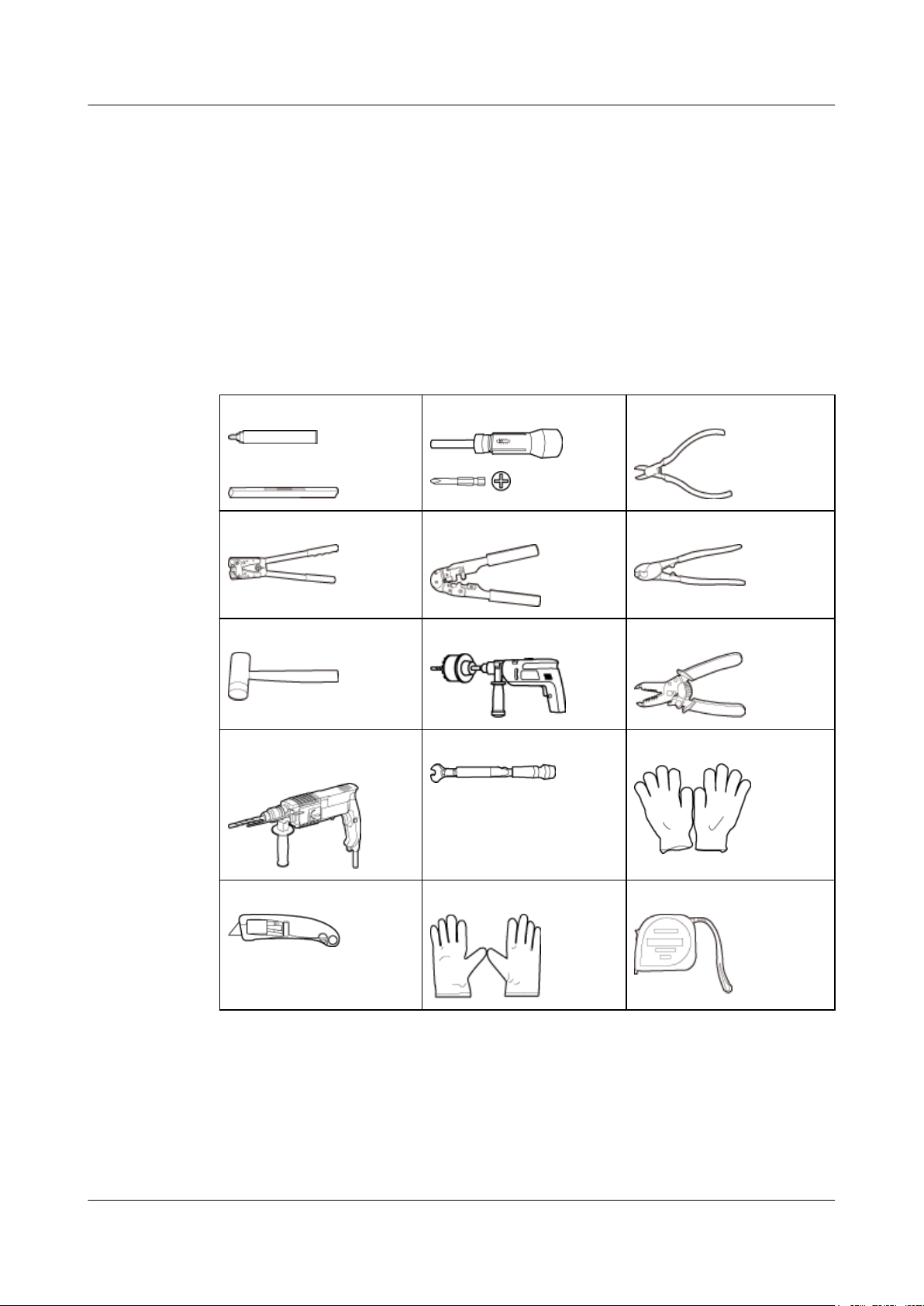
2.2 Preparing Tools and Instruments
This section describes the tools and instruments that must be prepared before the installation.
2 Installation Preparations
Marker
Level
Power cable crimping tool RJ11 crimping tool Cable cutter
Rubber mallet Crown saw (Ø60) Wire stripper
Hammer drill (Ø6, Ø8 and
Ø12)
Torque screwdriver
(M4 to M6)
Torque wrench (Ø10 mm) Protective gloves
Diagonal pliers
Guarded blade utility knife ESD gloves Long measuring tape
Issue 07 (2015-12-30) Huawei Proprietary and Confidential
Copyright © Huawei Technologies Co., Ltd.
6
Page 14
DBS3900 LampSite
Installation Guide
2 Installation Preparations
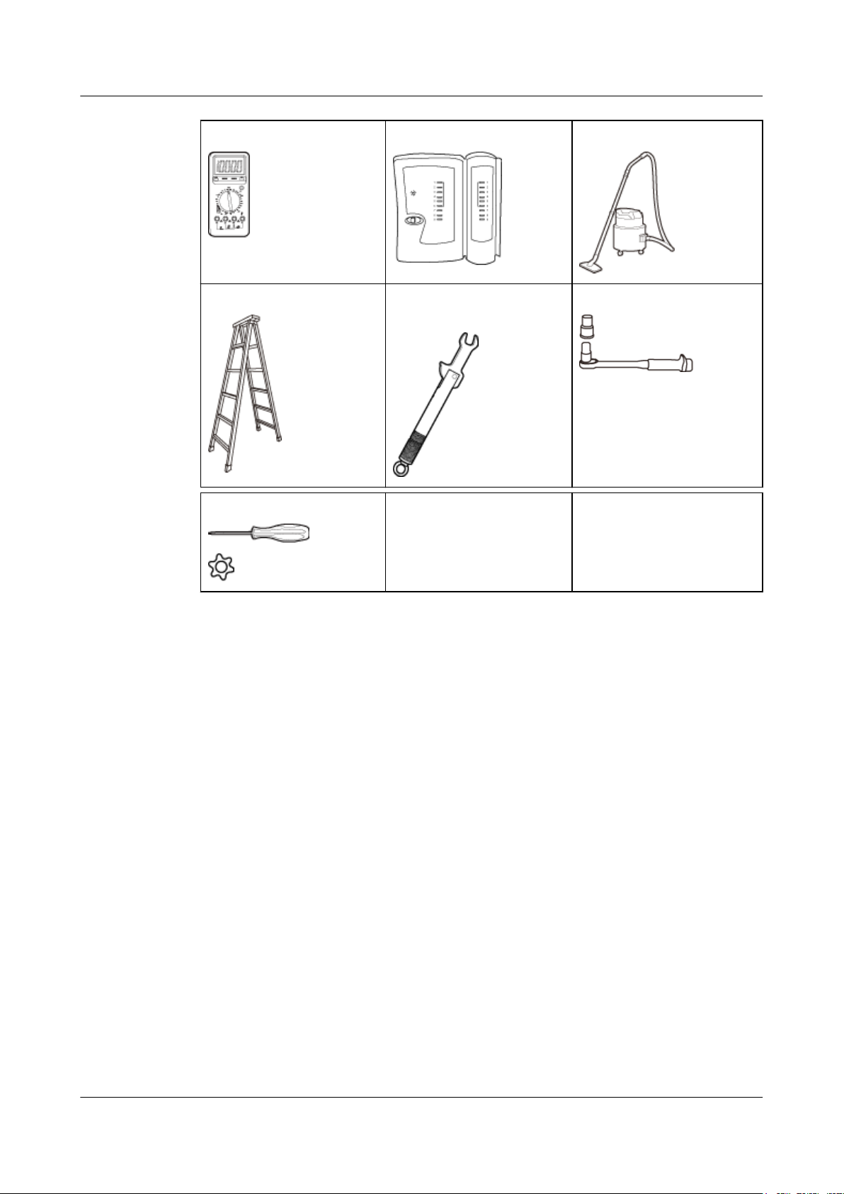
Multimeter Network cable tester Vacuum cleaner
Ladder Torque wrench for SMA
connector
Hole screwdriver (T20) – -
2.3 Requirements for Installation Personnel
This section describes requirements for installation engineers. They must be qualified and
trained, and familiar with correct operation methods and safety precautions before performing
any operations.
Socket wrench (M6)
Before the installation, pay attention to the following items:
l Technical engineers must take Huawei training and be familiar with proper installation
and operation methods.
l The number of installation personnel depends on the engineering schedule and
installation environment. Generally, three to five persons are required. Generally, only
three to five onsite personnel are necessary.
Issue 07 (2015-12-30) Huawei Proprietary and Confidential
Copyright © Huawei Technologies Co., Ltd.
7
Page 15
DBS3900 LampSite
Installation Guide
Context
3 Unpacking and Checking
3 Unpacking and Checking
This section describes how to unpack and check the delivered equipment to ensure that the
materials are complete and intact.
Procedure
Step 1 Count the total number of the shipments.
NOTE
The following lists important notes when you are transporting, lifting, or installing the equipment or
components:
l Protect them from colliding with doors, walls, shelves, or other objects.
l Wear clean gloves and do not touch them with bare hands, sweat-soaked gloves, or dirty gloves.
NOTICE
You must power on the RHUB or pRRU within 7 days after it is unpacked.
If...
The total number of the components is
consistent with that recorded in the
packing lists on all packing boxes
Then...
Go to Step 2.
The total number of the components is
inconsistent with that recorded in the
packing lists on all packing boxes
Step 2 Check the exterior of each packing box.
Issue 07 (2015-12-30) Huawei Proprietary and Confidential
Copyright © Huawei Technologies Co., Ltd.
Report the problems and causes to the local
Huawei office.
8
Page 16
DBS3900 LampSite
Installation Guide
Step 3 Check the type and quantity of the equipment in the boxes according to the packing list.
3 Unpacking and Checking
If... Then...
The exterior of each packing box is intact Go to Step 3.
It is damaged or soaked Report the problems and causes to the local
Huawei office.
The collision label is red Do not unpack the packing box and claim for
compensation from the transportation
company.
If...
The type and number are consistent with
the packing list on each packing list
There is any shortage, wrong delivery, or
damaged equipment
Then...
Sign the Packing List with the operator.
Report the problems and causes to the local
Huawei office.
NOTICE
Perform the following operations to protect the components from any damages and help find
out the cause of any damage in future: 1. Store the unpacked equipment and packing materials
indoors. 2. Take photos of the storeroom, rusted or eroded equipment, packing box, and
packing materials. 3. File the photos.
----End
Issue 07 (2015-12-30) Huawei Proprietary and Confidential
Copyright © Huawei Technologies Co., Ltd.
9
Page 17

DBS3900 LampSite
Installation Guide
4 Installing a BBU
4 Installing a BBU
This chapter describes the process of installing a BBU.
For details about the installation of the BBU, see DBS3900 Installation Guide.
Issue 07 (2015-12-30) Huawei Proprietary and Confidential
Copyright © Huawei Technologies Co., Ltd.
10
Page 18

DBS3900 LampSite
Installation Guide
5 Installing a DCU
5 Installing a DCU
This chapter describes the process of installing a DCU.
For details about the installation of the DCU, see DCU3900 Installation Guide.
Issue 07 (2015-12-30) Huawei Proprietary and Confidential
Copyright © Huawei Technologies Co., Ltd.
11
Page 19

DBS3900 LampSite
Installation Guide
About This Chapter
This chapter describes the process of installing an RHUB. RHUBs are classified into those
with electrical transmission ports and those with no electrical transmission ports. Unless
otherwise specified, this document uses the RHUBs with no electrical transmission ports as an
example.
6 Installing an RHUB
6 Installing an RHUB
6.1 Information About the Installation
This section describes the information to be learnt before RHUB installation, including the
RHUB installation scenarios, clearance, and installation environment.
6.2 Installation Process
The RHUB installation involves installing an RHUB module, installing RHUB cables,
checking the RHUB hardware installation, and powering on the RHUB.
6.3 Installing an RHUB
An RHUB can be installed in a cabinet, rack, shelf, or on a wall.
6.4 Installing RHUB Cables
This section describes how to install cables for an RHUB.
6.5 Checking the RHUB Hardware Installation
After an RHUB is installed, check the installation of hardware including the devices and
related cables.
6.6 Power-on Check on an RHUB
This section describes the power-on check on the RHUB after the RHUB hardware is
installed and checked.
Issue 07 (2015-12-30) Huawei Proprietary and Confidential
Copyright © Huawei Technologies Co., Ltd.
12
Page 20
DBS3900 LampSite
Installation Guide
6.1 Information About the Installation
This section describes the information to be learnt before RHUB installation, including the
RHUB installation scenarios, clearance, and installation environment.
6.1.1 Installation Scenarios
An RHUB can be installed in a 19-inch cabinet, rack, shelf, or on a wall.
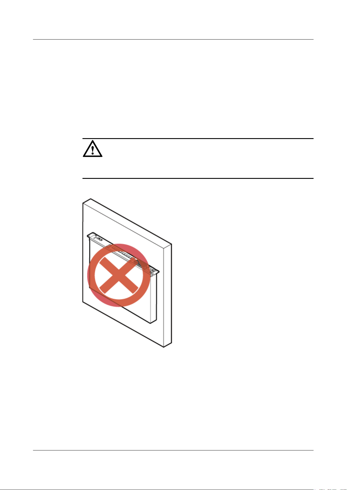
NOTICE
To prevent the RHUB from water drops, the RHUB panel must not face upwards (shown in
Figure 6-1) in any installation scenarios.
Figure 6-1 Improper installation mode
6 Installing an RHUB
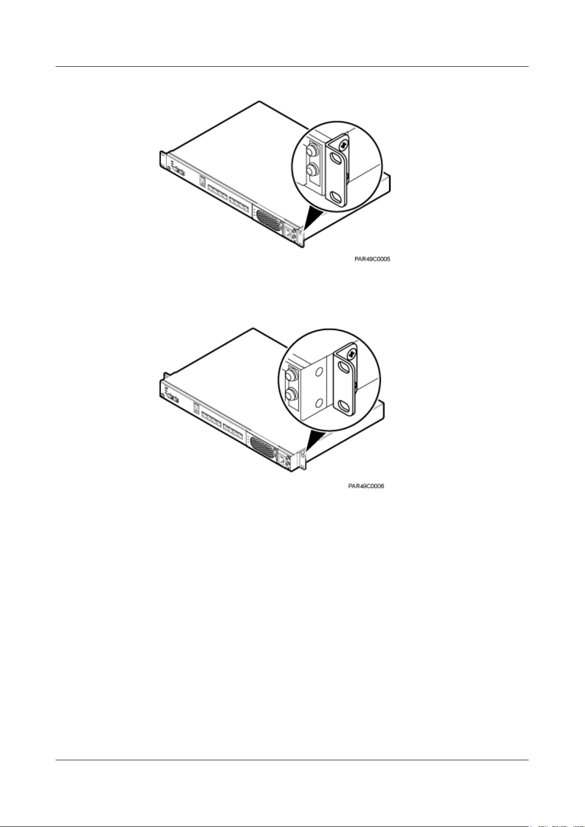
The RHUB mounting ears are installed in standard mode or reverse mode. The reverse mode
is used by default. The two installation modes are defined as follows:
l In standard mode, the front of the mounting ear is aligned with the RHUB panel, as
shown in Figure 6-2.
Issue 07 (2015-12-30) Huawei Proprietary and Confidential
Copyright © Huawei Technologies Co., Ltd.
13
Page 21
DBS3900 LampSite
Installation Guide
6 Installing an RHUB
Figure 6-2 Installing mounting ears in standard mode
l In reverse mode, the front of the mounting ear is 31 mm away from the RHUB panel, as
shown in Figure 6-3.
Figure 6-3 Installing mounting ears in reverse mode
Installing an RHUB in a 19-Inch Cabinet or Rack
Installing an RHUB in a 19-inch cabinet or rack: Secure the mounting ear to the mounting
bracket by using M6 screws.
l If there are no other modules installed in the 1 U space near the RHUB, install the
RHUB directly. Otherwise, remove the modules before installing the RHUB.
l Before installation, you need to check the installation mode supported by the rack and
adjust the position of the mounting ear.
Figure 6-4 and Figure 6-5 show RHUBs installed in a cabinet or rack, respectively.
Issue 07 (2015-12-30) Huawei Proprietary and Confidential
Copyright © Huawei Technologies Co., Ltd.
14
Page 22
DBS3900 LampSite
Installation Guide
6 Installing an RHUB
Figure 6-4 Installing an RHUB in a 19-inch cabinet or rack in standard mode
Figure 6-5 Installing an RHUB in a 19-inch cabinet in reverse mode
Installing an RHUB in a 19-Inch Shelf
When an RHUB is installed in a 19-inch shelf, the shelf must be installed on a wall. One shelf
can house multiple RHUBs with 1 U space between two RHUBs.
Figure 6-6 and Figure 6-7 show RHUBs installed in a 19-inch shelf.
Issue 07 (2015-12-30) Huawei Proprietary and Confidential
Copyright © Huawei Technologies Co., Ltd.
15
Page 23
DBS3900 LampSite
Installation Guide
6 Installing an RHUB
Figure 6-6 RHUB installed in a 19-inch shelf in standard mode
Issue 07 (2015-12-30) Huawei Proprietary and Confidential
Copyright © Huawei Technologies Co., Ltd.
16
Page 24
DBS3900 LampSite
Installation Guide
6 Installing an RHUB
Figure 6-7 RHUB installed in a 19-inch shelf in reverse mode
Installing an RHUB on a Wall
An RHUB can be installed on a wall.
The wall on which an RHUB is installed must meet the following requirements:
l When a single RHUB is installed, the wall must have a capacity of bearing at least four
times the weight of the RHUB.
l Expansion bolts must be tightened to 10 N·m (88.507 bf·in.) to ensure the bolts work
properly and the wall remains intact without cracks in it.
Figure 6-8 shows an RHUB installed on a wall.
Issue 07 (2015-12-30) Huawei Proprietary and Confidential
Copyright © Huawei Technologies Co., Ltd.
17
Page 25
DBS3900 LampSite
Installation Guide
6 Installing an RHUB
Figure 6-8 RHUB installed on a wall
6.1.2 Installation Clearance Requirements
When an RHUB is installed in a 19-inch cabinet, rack, shelf, or on a wall, a minimum
clearance is required for easy cabling and operation and maintenance. A recommended
installation clearance is provided based on experience.
NOTICE
l Do not install or place inflammable materials above or under an RHUB.
l A clearance of 350 mm must be reserved in front of the air intake vent of the fan of the
power supply unit (PSU) for maintenance.
Figure 6-9 shows the installation clearance for the RHUB installed in a 19-inch cabinet, rack,
or shelf.
Issue 07 (2015-12-30) Huawei Proprietary and Confidential
Copyright © Huawei Technologies Co., Ltd.
18
Page 26
DBS3900 LampSite
Installation Guide
6 Installing an RHUB
Figure 6-9 Installation clearance for an RHUB installed in a 19-inch cabinet, rack, or shelf
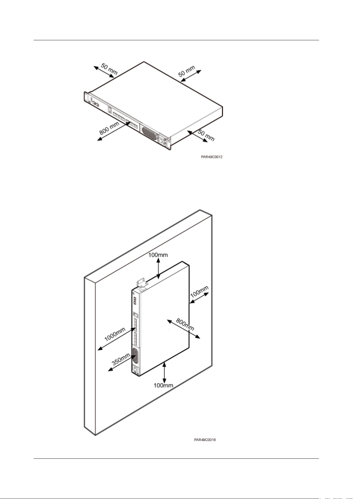
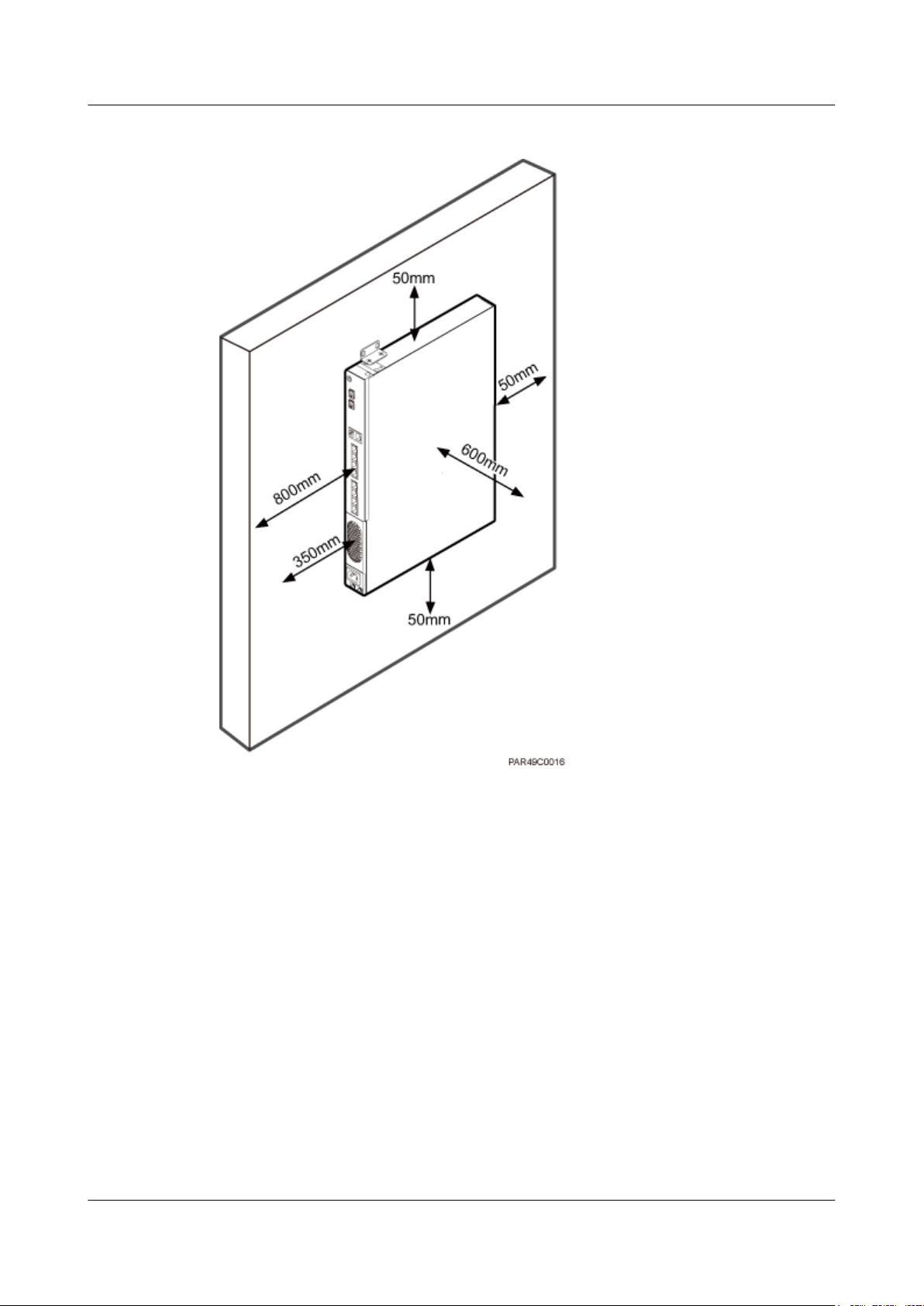
Figure 6-10 and Figure 6-11 shows the recommended and minimum installation clearance
respectively when the RHUB is installed on a wall.
Figure 6-10 Recommended installation clearance for a wall-mounted RHUB (unit: mm)
Issue 07 (2015-12-30) Huawei Proprietary and Confidential
Copyright © Huawei Technologies Co., Ltd.
19
Page 27
DBS3900 LampSite
Installation Guide
6 Installing an RHUB
Figure 6-11 Minimum installation clearance for a wall-mounted RHUB (unit: mm)
6.1.3 Installation Environment
The installation environment of an RHUB involves the running environment specifications
for the RHUB and other specifications.
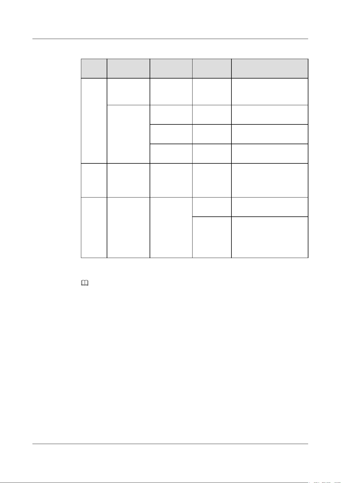
RHUB Running Environment Specifications
Table 6-1 shows the environment specifications for the RHUB installed indoors.
l The temperature and humidity of the installation position must ensure normal operation.
A cool and ventilated place is recommended.
l The heat dissipation holes on the RHUB cannot be blocked.
Issue 07 (2015-12-30) Huawei Proprietary and Confidential
Copyright © Huawei Technologies Co., Ltd.
20
Page 28
DBS3900 LampSite
Installation Guide
6 Installing an RHUB
Table 6-1 RHUB environment specifications
Specifi
cations
Operati
ng
tempera
Installation
Scenario
Installed on a
wall or in a 19inch rack.
RHUB
Condition Remarks
Quantity
N/A -5°C to
+50°C
ture
Installed in a
shelf.
1 -5°C to
+45°C
2 -5°C to
+43°C
3 -5°C to
+40°C
Relativ
e
Installed in all
scenarios.
N/A 5% RH to
95% RH
humidit
y
Altitude N/A N/A -60 m to
+1800 m
1800 m to
4000 m
N/A
N/A
N/A
N/A
N/A
Works properly.
Above the 1800 m altitude,
the maximum operating
temperature decreases by
1°C each time the altitude
increases by 220 m.
NOTE
Installing more than one RHUB, 1 U space is required between two RHUBs.
Other Running Environment Specifications
l The RHUB cannot be installed at an air outlet of the heat dissipation box of an air
conditioner or other heat-generating appliances.
l The RHUB cannot be installed near a strong heat source.
l The RHUB cannot be installed in a position with water dripping, such as outdoor
equipment of air conditioners, pipe, and leaking or dripping roofs.
l The installation position must be far from rains. If the RHUB is installed on a wall, there
must be no window on either side of the wall.
l The installation position must be far away from high voltage, highly corrosive devices,
flammable or explosive substances, and electromagnetic interference such as power
stations, high-voltage substations, and wired TV towers.
l The RHUB must be installed in a dry, ventilating, and dust-proof place.
l If the RHUB is installed in parking areas or basements, the installation position must be
well-ventilated.
Issue 07 (2015-12-30) Huawei Proprietary and Confidential
Copyright © Huawei Technologies Co., Ltd.
21
Page 29
DBS3900 LampSite
Installation Guide
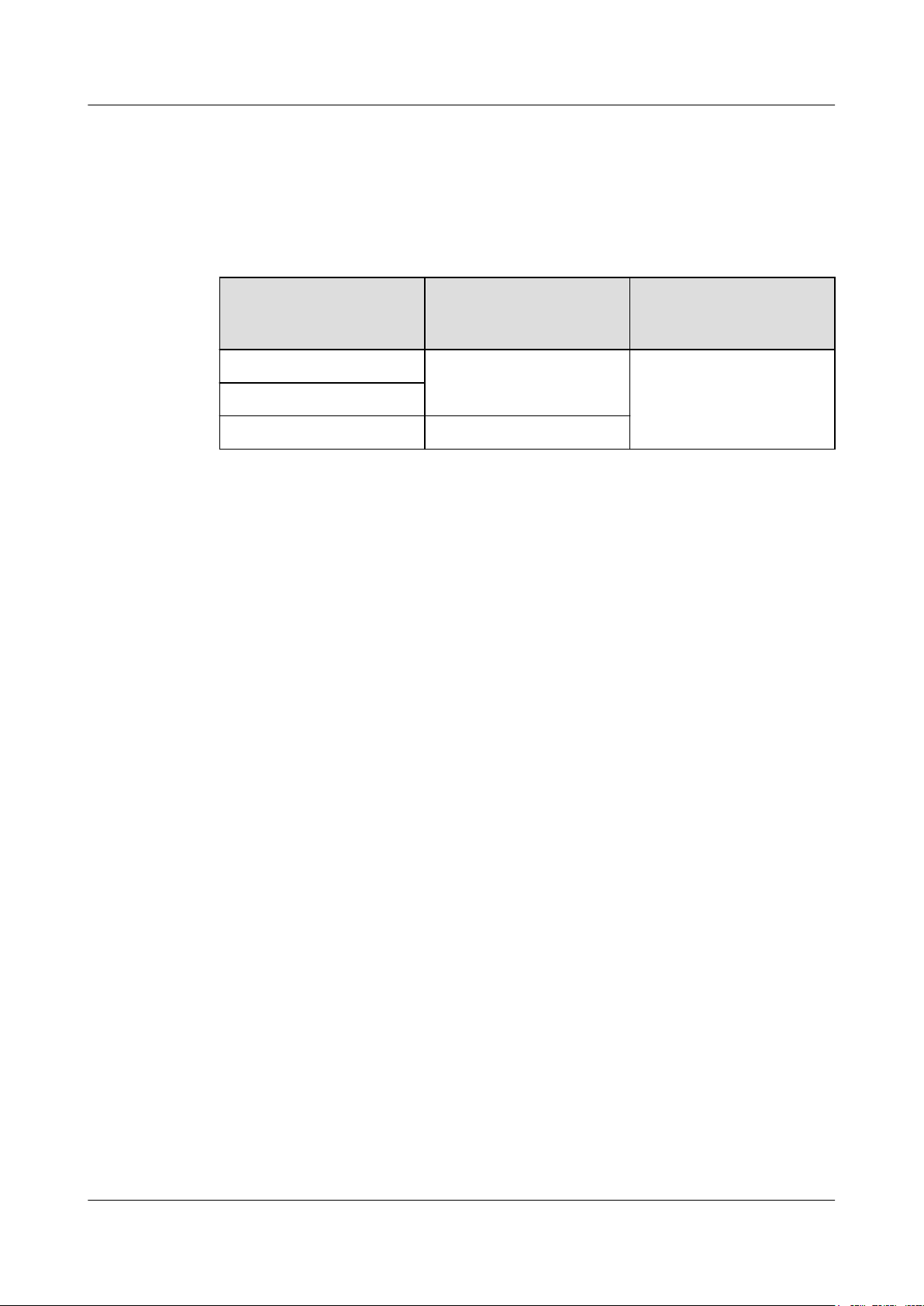
Requirements for the Upper-level Circuit Breaker
Type C upper-level AC circuit breakers or slow-blow fuses must be used for power cables.
The maximum current must not exceed 16 A. Table 6-2 describes the recommended
specifications.
Table 6-2 Circuit breaker specifications for power cables
6 Installing an RHUB
Power Supply
220 V AC single-phase ≥ 6 A
110 V AC dual-live-wire
110 V AC single-phase ≥ 12 A
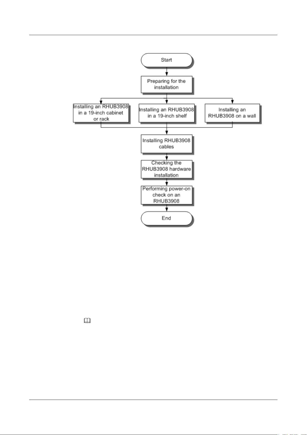
6.2 Installation Process
The RHUB installation involves installing an RHUB module, installing RHUB cables,
checking the RHUB hardware installation, and powering on the RHUB.
Figure 6-12 shows the RHUB installation process.
Upper-level AC Circuit
Breaker (For a single
RHUB)
Cross-Sectional Area of
the Input Power Cable
1.5 mm
2
Issue 07 (2015-12-30) Huawei Proprietary and Confidential
Copyright © Huawei Technologies Co., Ltd.
22
Page 30
DBS3900 LampSite
Installation Guide
6 Installing an RHUB
Figure 6-12 RHUB installation process
6.3 Installing an RHUB
An RHUB can be installed in a cabinet, rack, shelf, or on a wall.
6.3.1 Installing an RHUB in a 19-Inch Cabinet or Rack
This section describes how to install an RHUB in a 19-inch cabinet.
Procedure
l The following describes how to install an RHUB with mounting ears in reverse mode:
NOTE
If necessary, request one more person for assistance.
a. With one hand holding it, align the mounting holes with the installation holes,
slowly push the RHUB into the required position in the cabinet, as shown in Figure
6-13.
Issue 07 (2015-12-30) Huawei Proprietary and Confidential
Copyright © Huawei Technologies Co., Ltd.
23
Page 31

DBS3900 LampSite
Installation Guide
6 Installing an RHUB
Figure 6-13 Pushing an RHUB into a cabinet
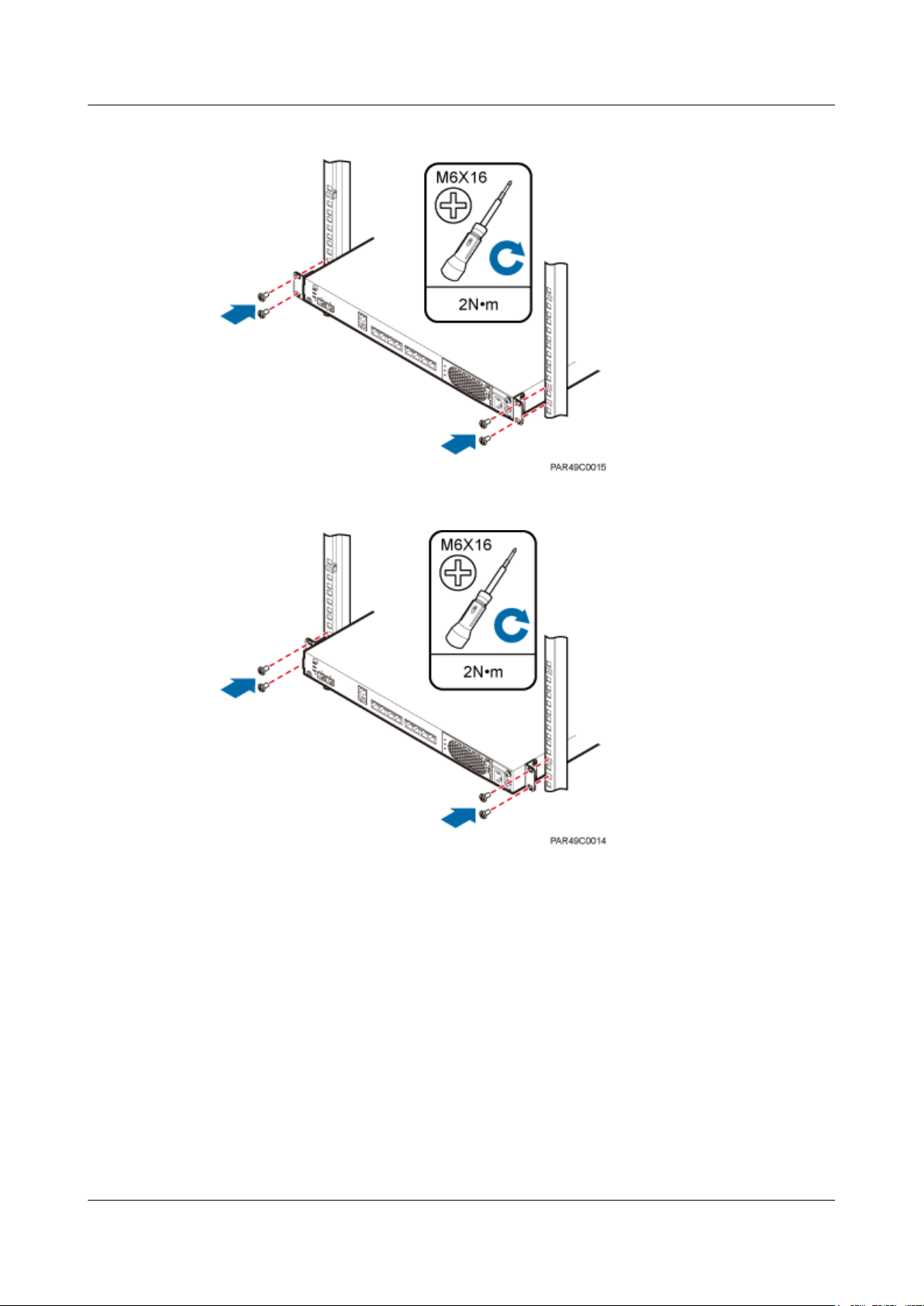
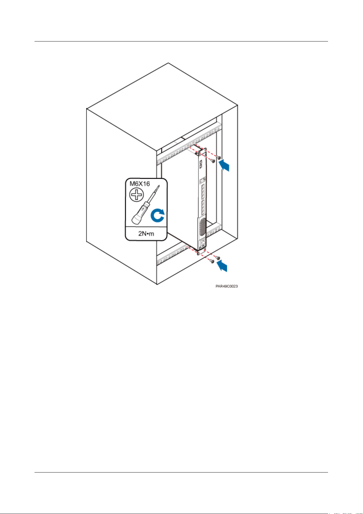
b. Use a torque screwdriver or Phillips screwdriver to tighten the four M6×16 screws
with a torque of 2 N•m, as shown in Figure 6-14.
Figure 6-14 Tightening screws
l The following describes how to install an RHUB with mounting ears aligned with the
RHUB panel:
NOTE
If necessary, request one more person for assistance.
a. Remove the mounting ears on both sides of the RHUB by removing the four M4×8
screws, as shown in Figure 6-15.
Issue 07 (2015-12-30) Huawei Proprietary and Confidential
Copyright © Huawei Technologies Co., Ltd.
24
Page 32

DBS3900 LampSite
Installation Guide
6 Installing an RHUB
Figure 6-15 Removing mounting ears and screws
b. Use a torque screwdriver or Phillips screwdriver to tighten the four M4×8 screws
with a torque of 1.4 N•m to install the removed mounting ears again, as shown in
Figure 6-16. The mounting ears must be aligned with the RHUB panel.
Figure 6-16 Installing mounting ears in standard mode
c. With one hand holding it, align the mounting holes with the installation holes,
slowly push the RHUB into the required position in the cabinet, as shown in Figure
6-17.
Issue 07 (2015-12-30) Huawei Proprietary and Confidential
Copyright © Huawei Technologies Co., Ltd.
25
Page 33

DBS3900 LampSite
Installation Guide
6 Installing an RHUB
Figure 6-17 Pushing an RHUB into a cabinet
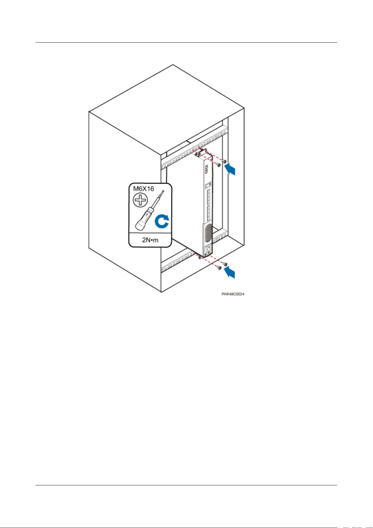
d. Use a torque screwdriver or Phillips screwdriver to tighten the four M6×16 screws
with a torque of 2 N•m, as shown in Figure 6-18.
Figure 6-18 Tightening screws
----End
6.3.2 Installing an RHUB in a 19-Inch Shelf
If a shelf houses more than one RHUB, 1 U space is required between two RHUBs. The PSU
must be installed at the bottom of the cabinet.
Procedure
l The following describes how to install an RHUB with mounting ears installed in reverse
mode:
NOTE
If necessary, request one more person for assistance.
Issue 07 (2015-12-30) Huawei Proprietary and Confidential
Copyright © Huawei Technologies Co., Ltd.
26
Page 34

DBS3900 LampSite
Installation Guide
6 Installing an RHUB
a. With one hand holding it, align the mounting holes with the installation holes,
slowly push the RHUB into the required position in the shelf.
b. Use a torque screwdriver or Phillips screwdriver to tighten the four M6×16 screws
with a torque of 2 N•m, as shown in Figure 6-19.
Figure 6-19 Tightening screws
l The following describes how to install an RHUB with mounting ears installed in
standard mode:
NOTE
If necessary, request one more person for assistance.
a. Remove the mounting ears on both sides of the RHUB by removing the four M4×8
screws, as shown in Figure 6-20.
Issue 07 (2015-12-30) Huawei Proprietary and Confidential
Copyright © Huawei Technologies Co., Ltd.
27
Page 35

DBS3900 LampSite
Installation Guide
6 Installing an RHUB
Figure 6-20 Removing mounting ears and screws
b. Use a torque screwdriver or Phillips screwdriver to tighten the four M4×8 screws
with a torque of 1.4 N•m to install the removed mounting ears again, as shown in
Figure 6-21. The mounting ears must be aligned with the RHUB panel.
Figure 6-21 Installing mounting ears in standard mode
c. With one hand holding it, align the mounting holes with the installation holes,
slowly push the RHUB into the required position in the cabinet, as shown in .
d. Use a torque screwdriver or Phillips screwdriver to tighten the four M6×16 screws
with a torque of 2 N•m, as shown in Figure 6-22.
Issue 07 (2015-12-30) Huawei Proprietary and Confidential
Copyright © Huawei Technologies Co., Ltd.
28
Page 36

DBS3900 LampSite
Installation Guide
6 Installing an RHUB
Figure 6-22 Tightening screws
----End
6.3.3 Installing an RHUB on a Wall
An RHUB can be installed on a wall.
Procedure
Step 1 The mounting ears are installed in reverse mode by default. Before installing an RHUB on a
wall, modify the installation mode of the mounting ears on the RHUB.
l Use a torque screwdriver or Phillips screwdriver to remove the mounting ears on both
sides of the RHUB by removing the four M4×8 screws, as shown in Figure 6-23.
Issue 07 (2015-12-30) Huawei Proprietary and Confidential
Copyright © Huawei Technologies Co., Ltd.
29
Page 37

DBS3900 LampSite
Installation Guide
6 Installing an RHUB
Figure 6-23 Removing screws and mounting ears
l Rotate the mounting ears 90 degrees clockwise, and use a torque screwdriver or Phillips
screwdriver to secure the mounting ear with a torque of 1.4 N•m, as shown in Figure
6-24.
Figure 6-24 Installing mounting ears and screws
Step 2 Determine the position on the wall for installing the RHUB based on the requirements in the
engineering blueprint and 6.1.2 Installation Clearance Requirements. Place the RHUB to
the position to be installed against the wall, and then mark the four anchor points where the
mounting ear screws are fastened using a marker, as shown in Figure 6-25.
Issue 07 (2015-12-30) Huawei Proprietary and Confidential
Copyright © Huawei Technologies Co., Ltd.
30
Page 38

DBS3900 LampSite
Installation Guide
6 Installing an RHUB
Figure 6-25 Anchor points for installing an RHUB on a wall
(1) Level (2) RHUB (3) Wall
CAUTION
To prevent inhalation or eye contact with dust, take adequate preventive measures when
drilling holes.
Step 3 Drill holes at the anchor point and install expansion bolts, as shown in Figure 6-26.
Issue 07 (2015-12-30) Huawei Proprietary and Confidential
Copyright © Huawei Technologies Co., Ltd.
31
Page 39

DBS3900 LampSite
Installation Guide
6 Installing an RHUB
Figure 6-26 Drilling holes and installing expansion bolts
(1) M6×60
expansion bolt
(2) Nut (3) Spring washer (4) Flat washer (5) Extension tub
1. Use a hammer drill with bit 8 to drill holes with a diameter of 8 mm and a depth of 45
mm to 50 mm at the marked anchor points. All the holes have the same depth.
2. Use a vacuum cleaner to clear the dust inside and around each hole. If the distance
between two holes is incorrect, mark and drill holes again.
3. Partially tighten an expansion bolt and place it vertically into each hole.
4. Use a rubber mallet to hit the expansion bolt until the entire expansion sleeve is in the
hole.
5. Remove the M6×60 bolt, nut, spring washer, and flat washer from each expansion bolt in
sequence.
NOTICE
After removing an expansion bolt, ensure that the top of the expansion sleeve is level
with the wall. If it is not level, the RHUB cannot be installed on the concrete floor
evenly and securely.
Step 4 Align the mounting holes with the four M6×60 expansion bolts. Install spring washer 6 and
flat washer 6 in sequence on each M6×60 expansion bolt, insert the bolts to each expansion
tub, and then use a torque wrench or socket wrench to tighten the four M6×60 bolts with a
torque of 5 N•m to secure the RHUB to the wall, as shown in Figure 6-27.
Issue 07 (2015-12-30) Huawei Proprietary and Confidential
Copyright © Huawei Technologies Co., Ltd.
32
Page 40

DBS3900 LampSite
Installation Guide
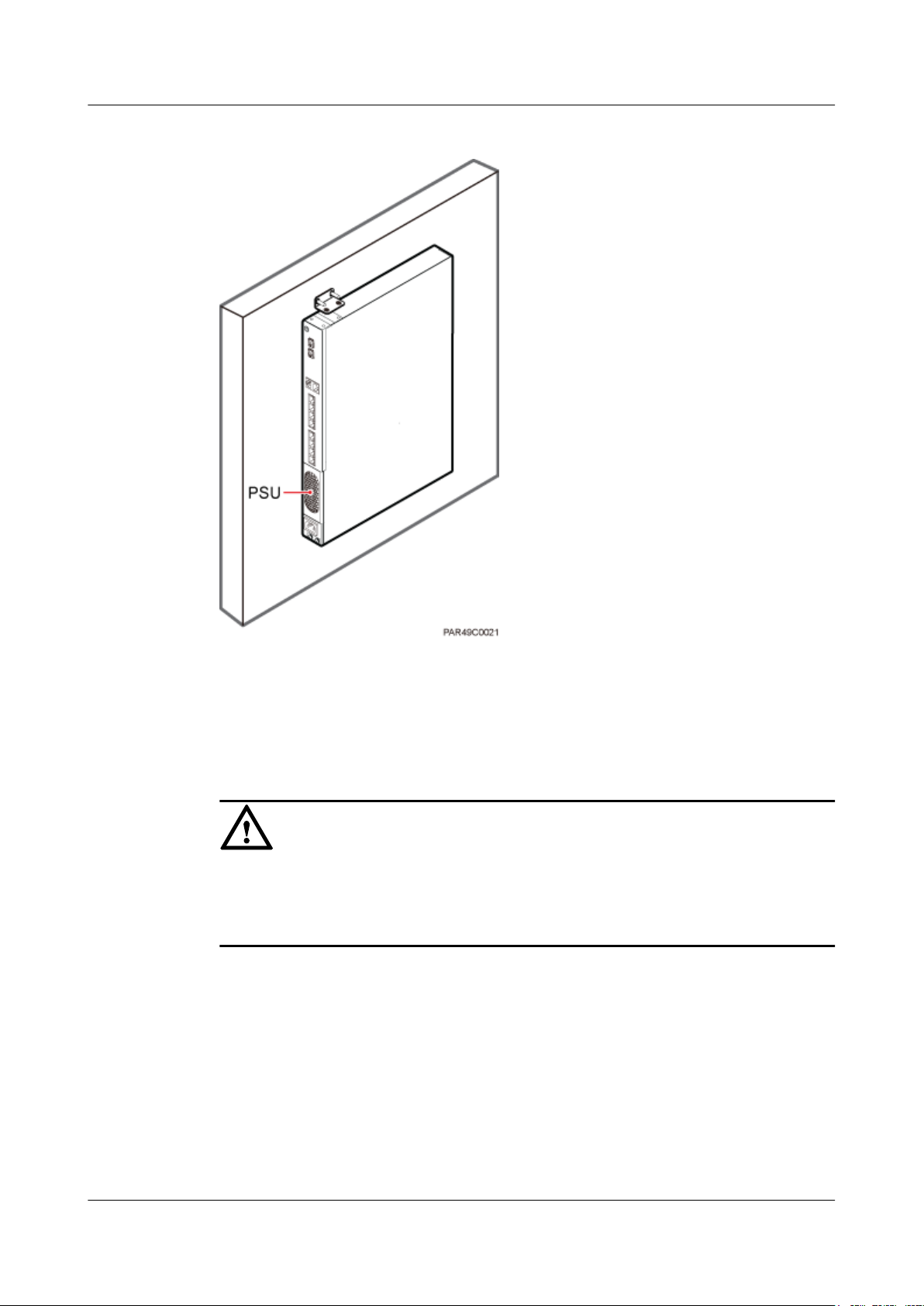
6 Installing an RHUB
Figure 6-27 Installing an RHUB on a wall
NOTE
As shown in the preceding figure, when the RHUB is placed against the wall, ensure that the RHUB
panel is vertical to the ground and the PSU is on the lower part of the RHUB panel.
----End
6.4 Installing RHUB Cables
This section describes how to install cables for an RHUB.
6.4.1 Requirements for Cable Layout
Cables must be routed according to the specified cabling requirements to prevent signal
interference.
NOTE
If a cable listed below is not required, skip the requirements for routing the cable.
General Requirements for Cable Layout
National Standards
Issue 07 (2015-12-30) Huawei Proprietary and Confidential
Copyright © Huawei Technologies Co., Ltd.
33
Page 41

DBS3900 LampSite
Installation Guide
6 Installing an RHUB
l Code for Engineering Design of Generic Cabling System for Building and Campus (GB
50311-2007)
l Code for Engineering Acceptance of Generic Cabling System for Building and Campus
(GB50312-2007).
l Security Protection Engineering Technology Specifications (GB 50348-2004)
l Code for Construction and Acceptance of the Electronic Information System Room (GB
50462-2008)
l Code for Quality Acceptance of the Intelligent Building Engineering (GB 50339-2003)
l Code for Quality Acceptance of Electric Engineering Construction in Building (GB
50303-2002)
l Technical Specification for Construction and Acceptance of Telecommunication Conduit
Engineering (GB 50374-2006)
International Standards
l Generic Cabling for Customer Premises (ISO/IEC 11801)
l Commercial Building Telecommunications Cabling Standard (EIA/TIA 568)
l Commercial Building Standard for Telecommunication Pathways and Spaces (EIA/TIA
569)
l Administration Standard for Commercial Telecommunications Infrastructure (EIA/TIA
606)
l Grounding and Bonding Requirements for Telecommunications in Commercial
Buildings (EIA/TIA 607)
l Generic Cabling Systems for Information Technology (EN 50173)
l Cabling Installation for Information Technology (EN 50174)
Bending radius
l The bending radius of a power cable or a protection ground (PGND) cable is at least five
times the diameter of the cable.
l The bending radius of an optical cable is at least 20 times the diameter of the optical
cable, and the minimum bending radius of the branch at each end of the optical cable is
30 mm.
l The bending radius of the signal cable must be at least five times the diameter of the
cable.
Cable Binding
l Cables of the same type are bound together.
l Different types of cables must be separately routed with a minimum spacing of 30 mm
and cannot be entangled or crossed.
l The cables are bound tightly and neatly and the cable sheath is intact.
l The cable ties face the same direction and all cable ties bound at similar positions must
be in a straight line.
l The extra length of each indoor cable tie must be cut off. A slack of 5 mm is reserved for
each outdoor cable tie. All cut surfaces have no sharp edges.
l Labels or nameplates are attached to both ends, joints, or turns of cables after they are
installed.
Safety
Issue 07 (2015-12-30) Huawei Proprietary and Confidential
Copyright © Huawei Technologies Co., Ltd.
34
Page 42

DBS3900 LampSite
Installation Guide
l The steel pipe or fire-resistant rigid polyvinyl chloride pipe should be used for the cable
duct or for routing cables. The cross-sectional usage of the cable duct should be 30% to
50% and that of the pipe for routing cables should be 25% to 30%.
l Cables are placed away from sharp objects or wall burrs. If these positions are inevitable,
protection pipes are required for the cables.
l Cables are routed away from heat sources, or heat-insulation materials are added
between cables and heat sources.
l Cables are routed away the cooling vents of the RHUB.
l A clearance is reserved at turns of a cable or the position close to a device, facilitating
cable and device maintenance. The recommended clearance is about 0.1 m.
Requirements for Special Cables
Ethernet Cable
l A maximum of 100 Ethernet cables can be bundled if no PVC pipes are used. If pipes are
used, a maximum of 24 Ethernet cables can be led through a pipe. In this case, ensure
that 1/3 space inside the pipes must be vacant.
l The point at which an Ethernet cable is bundled must be spaced 400 mm or less from the
Ethernet port on an RHUB.
l For the RHUB used in the elevator engine room on the rooftop, generator set for the
subway engine, and equipment room with central air conditioning, Ethernet cables must
be led through metallic conduits that are reliably grounded at both ends.
6 Installing an RHUB
Power cable
l Positions for routing power cables meet requirements of the engineering design.
l Cables are routed only by qualified and trained personnel before all preparations are
made.
l Cables are routed in an untangled and orderly fashion.
PGND cable
l PGND cables are buried in the ground or routed indoors. They cannot be routed
overhead before they are routed into the equipment room.
l Outer conductors of coaxial cables and both ends of the shield layers on shielded cables
are in proper electrical contact with the metal surface of the equipment to which they are
connected.
l PGND cables and signal cables are installed in an untangled and orderly fashion. A
certain distance is reserved between them to prevent interference from each other.
l Fuses or switches are not allowed on PGND cables.
l Other devices cannot be used for electrical connections of PGND cables.
l All the metal parts in the equipment are reliably connected to the ground terminal.
Optical cable
l Cables are routed in an untangled and orderly fashion.
l Optical fibers cannot be bound at turns.
l Optical fibers cannot be stretched with too much force or stepped on, and they are far
away from sharp objects. Heavy objects cannot be placed on optical cables.
l When optical cables are routed, the extra length of the cables is coiled around special
devices, such as a fiber coiler.
Issue 07 (2015-12-30) Huawei Proprietary and Confidential
Copyright © Huawei Technologies Co., Ltd.
35
Page 43

DBS3900 LampSite
Installation Guide
l Even strength is applied when optical cables are coiled and optical cables cannot be bent
l Vacant optical connectors are covered with dust-proof caps.
l Fiber optic cables cannot be squeezed by the cabinet door when routed through the
l If optical cables need to be routed on the tower platform, the optical cables are routed
l If optical cables need to be routed close to a device on the tower, the optical cables are
l If the optical cable close to a device on the tower is too long, the optical cables are
6.4.2 Cable List
This section describes the connector types and connections of the RHUB cables.
Table 6-3 lists RHUB cables.
6 Installing an RHUB
in a forcible manner.
cabinet.
along the inner side of the guard rail and the distance between the guard rail and the
cable is the shortest one.
secured to the guard rail or pole with cable clips and the device cannot be far away from
the position for securing the optical cables.
wrapped and secured to the tower.
Table 6-3 RHUB cable list
Cable
One End The Other End
Connector Connected
PGND cable OT terminal
(M4, 6 mm
[0.009 in.2])
Power
Supply Cable
CPRI Optical
C13 female
connector
DLC connector CPRI port on
Fiber
Connector Connected to...
to...
Ground screws
2
on the RHUB
AC power
input socket on
OT terminal
(M6, 6 mm
[0.009 in.2])
2
Ground terminal
on the external
ground bar
3-pin connector External power
input socket
the RHUB
DLC connector CPRI0 or CPRI1
the LBBP,
WBBP or
port on the
RHUB
UBBP in the
BBU
CPRI port on
the LBBP,
DLC connector CPRI port on the
DCU
WBBP or
UBBP in the
BBU
CPRI port on
the DCU
Issue 07 (2015-12-30) Huawei Proprietary and Confidential
Copyright © Huawei Technologies Co., Ltd.
CPRI0 or CPRI1
port on the
RHUB
36
Page 44

DBS3900 LampSite
Installation Guide
6 Installing an RHUB
Cable One End The Other End
Ethernet
Cable
Connector Connected
to...
CPRI0 or
CPRI1 port on
the RHUB
CPRI port on
the LBBP,
WBBP or
UBBP in the
BBU
CPRI port on
the DCU
CPRI0 or
CPRI1 port on
the RHUB
RJ45 connector CPRI_E0~CP
RI_E7 port on
the RHUB
RJ45 connector CPRI_E0~CP
RI_E7 port on
the RHUB
Connector Connected to...
DLC connector CPRI0 or CPRI1
port on the
RHUB
FC connector,
ODF
SC connector, or
LC connector
RJ45 connector CPRI_E0~CPRI_
E1 port on the
pRRU
RJ45 connector Protect port on
the PoE surge
protector 2
(Optional)
Alarm Cable
RJ45 connector Surge port on
the PoE surge
protector 2
RJ45 connector Protect port on
the PoE surge
protector 1
RJ45 connector EXT_ALM
port on the
RHUB
RJ45 connector Surge port on the
PoE surge
protector 1
RJ45 connector CPRI_E0~CPRI_
E1 port on the
pRRU3902
Bare end Alarm signal port
of the monitored
equipment
Issue 07 (2015-12-30) Huawei Proprietary and Confidential
Copyright © Huawei Technologies Co., Ltd.
37
Page 45

DBS3900 LampSite
Installation Guide
NOTE
l If one end of the CPRI cable is connected to the DLC connector, the other end connects the BBU,
DCU or RHUB through the DLC connector. If one end of the CPRI cable is connected to the ODF
adapter, the other end connects the BBU or RHUB through a connector corresponding to the adapter.
The connectors include the FC connector, SC connector, and LC connector.
l The Extender can be used to lengthen the distance between the RHUB and the pRRU connected
using the Ethernet cable. If the Extender is used, the Ethernet cable is divided into two parts, one
between the RHUB and the Extender and the other between the Extender and the pRRU.
l
l When the RHUB and the pRRU connected using the Ethernet cable. If the Extender is used,
l In the indoor scenario, the Ethernet cable is divided into two parts, one between the RHUB
and the Extender and the other between the Extender and the pRRU.
l In the outdoor scenario (only pRRU3901 and pRRU3902) , the Ethernet cable is divided into
two parts, one among RHUB-PoE surge protector 2- PoE surge protector 3-Extender and the
other among the Extender- PoE surge protector 4- PoE surge protector 1-pRRU.
6.4.3 Cable Connections
This section describes the cable connections for an RHUB.
6 Installing an RHUB
Figure 6-28, Figure 6-29 shows the cable connections for an RHUB. The port of ETH are
reserved.
Figure 6-28 Cable connections for an RHUB (indoor)
(1) CPRI optical cable (2) Alarm cable (3) Ethernet cable
(4) Power cable (5) PGND cable -
NOTE
The Extender can be used to lengthen the distance between the RHUB and the pRRU connected using
the Ethernet cable. If the Extender is used, the Ethernet cable is divided into two parts, one between the
RHUB and the Extender and the other between the Extender and the pRRU.
Issue 07 (2015-12-30) Huawei Proprietary and Confidential
Copyright © Huawei Technologies Co., Ltd.
38
Page 46

DBS3900 LampSite
Installation Guide
6 Installing an RHUB
Figure 6-29 Cable connections for an RHUB (outdoor)
(1) CPRI optical cable (2) Alarm cable (3) Ethernet cable
(4) Power cable (5) PGND cable -
NOTE
The Extender can be used to lengthen the distance between the RHUB and the pRRU connected using
the Ethernet cable. If the Extender is used, the Ethernet cable is divided into two parts, one between the
RHUB and the Extender and the other between the Extender and the pRRU.
6.4.4 Cable Installation Process
This section describes the process of installing RHUB cables.
Figure 6-30 shows the RHUB cable installation process.
Issue 07 (2015-12-30) Huawei Proprietary and Confidential
Copyright © Huawei Technologies Co., Ltd.
39
Page 47

DBS3900 LampSite
Installation Guide
6 Installing an RHUB
Figure 6-30 RHUB cable installation process
6.4.5 Installing PGND Cable
An RHUB PGND cable ensures proper grounding of an RHUB.
Prerequisites
The OT terminals at both ends of the PGND cable are prepared.
Context
The yellow and green or green PGND cable is a single cable. The cross-sectional area of the
PGND cable is 6 mm2 (0.009 in.2). Both ends of the cable are OT terminals, as shown in
Figure 1.
Figure 6-31 Exterior of a PGND cable
2
(1) OT terminal (6 mm
[0.009 in.2], M4) (2) OT terminal (6 mm2 [0.009 in.2], M6)
Issue 07 (2015-12-30) Huawei Proprietary and Confidential
Copyright © Huawei Technologies Co., Ltd.
40
Page 48

DBS3900 LampSite
Installation Guide
6 Installing an RHUB
NOTE
l If the PGND cable is provided by the customer, a copper-core cable with a minimum cross-sectional
area of 6 mm2 (0.009 in.2) or 10 AWG is recommended.
l The OT terminals at both ends of the PGND cable are assembled at the site.
l The M6 OT terminal has the default size. You can replace it with another OT terminal of the
expected size based on the site requirement.
NOTICE
l Ensure proper grounding of the RHUB using a PGND cable.
l When installing the PGND cable, tightly press the OT terminal in the correct direction, as
shown in Figure 6-32.
Figure 6-32 Correct direction of an OT terminal for the PGND cable
Procedure
Step 1 Route the PGND cable by referring to 6.4.1 Requirements for Cable Layout.
Step 2 Use a torque screwdriver or Phillips screwdriver to secure the M4 OT terminal at one end of
the PGND cable to the ground screw on the RHUB panel with a torque of 1.4 N•m. If the OT
terminal is a one-hole OT terminal, connect it to the ground screw on the lower part of the
RHUB panel, as shown in Figure 6-33.
Issue 07 (2015-12-30) Huawei Proprietary and Confidential
Copyright © Huawei Technologies Co., Ltd.
41
Page 49

DBS3900 LampSite
Installation Guide
Step 3 Use a torque screwdriver or Phillips screwdriver to secure the M8 OT terminal at one end of
6 Installing an RHUB
Figure 6-33 Installing an RHUB PGND cable
the PGND cable to the wiring terminal on the ground bar at the site with a torque of 1.4 N•m.
----End
Follow-up Procedure
1. Route the cable, and then use a cable tie to bind the cable. For details, see 6.4.1
Requirements for Cable Layout.
2. Label the installed cable. For details, see section 14.4 Attaching an L-Shaped Label.
6.4.6 Installing Ethernet Cable
This section describes how to install an Ethernet cable.
Prerequisites
l The Ethernet cable must be of Category 5e (enhanced) or higher. In addition, its cross-
sectional area must be 24 AWG or larger and frame spread rating must be CM or higher.
l The Ethernet cables can be straight-through cables or crossover cables.
l With the internal PoE module providing power, the maximum length of an Ethernet
cable is 100 m. With the Extender, the distance of the pRRU and RHUB can be extended
by the Extender up to a total distance of 200 m.
l Ethernet cables are not delivered, and they must be prepared onsite. You need to use a
network cable tester to test the Ethernet cable connection.
Context
The Ethernet cable has the following functions:
l Provides power supply for the pRRU when connected to the CPRI_E0 port on the
pRRU.
l Transmits CPRI signals between an RHUB and a pRRU.
For details about the cable connections in the different scenarios, see 6.4.3 Cable
Connections. The Ethernet cable connections between RHUB and pRRUs are the same. The
Issue 07 (2015-12-30) Huawei Proprietary and Confidential
Copyright © Huawei Technologies Co., Ltd.
42
Page 50

DBS3900 LampSite
Installation Guide
Procedure
Step 1 Make the Ethernet cables.
6 Installing an RHUB
following section describes the connections between RHUB-Extender-pRRU3901 as an
example.
In the outdoor scenario, PoE surge protector is needed to provide surge protection for the
Ethernet ports. For details about the installation of PoE surge protector, see 10 (Optional)
Installing the PoE Surge Protector and Cables.
1. Assemble an RJ45 connector and an Ethernet cable by following instructions in
Assembling the Unshielded RJ45 Connector and the Ethernet Cable of Installation
Reference.
NOTE
Follow pin assignment instructions described in section Ethernet Cable in DBS3900 LampSite
Hardware Description to assemble the unshielded RJ45 connector and the Ethernet cable. Otherwise,
the transmission signal quality deteriorates and CPRI links may be disconnected.
2. Check whether the made RJ45 connector is qualified by following instructions in
Checking the Appearance of Metal Contact Strips.
3. To complete the assembly of the other end, repeat Step 1.1 and Step 1.2.
4. Check whether the touch points on the connectors at both ends are normally conducted
and well contacted and whether the connections are correct by following instructions in
Testing the Connection of Assembled Cables of Installation Reference.
Step 2 Connect the RJ45 connector at the other end of the Ethernet cable to any port ranging from
CPRI_E0 to CPRI_E7 on the RHUB panel based on the engineering design.
Step 3 Optional: Connect the RJ45 connector at the other end of the Ethernet cable to the output
port of the Extender. Then, connect the RJ45 connector at one end of another Ethernet cable
to the input port of the Extender.
If the Extender is used, the Ethernet cable is divided into two parts, one between the RHUB
and the Extender and the other between the Extender and the pRRU.
Step 4 Remove the dustproof cap of the CPRI_E0 port on the pRRU.
Step 5 Connect the RJ45 connector at one end of the Ethernet cable to the CPRI_E0 port on the
pRRU panel, as shown in Figure 6-34, Figure 6-35.
Figure 6-34 Install an Ethernet cable between an RHUB and a pRRU3901
(1) Ethernet cable (2) CPRI_E0 port on the pRRU3901
Issue 07 (2015-12-30) Huawei Proprietary and Confidential
Copyright © Huawei Technologies Co., Ltd.
43
Page 51

DBS3900 LampSite
Installation Guide
6 Installing an RHUB
Figure 6-35 Install an Ethernet cable between an RHUB and a pRRU3902 or pRRU3911
(1) Ethernet cable (2) CPRI_E0 port on the pRRU3902
Figure 6-36 Install an Ethernet cable between an RHUB and a pRRU3907
(1) Ethernet cable (2) CPRI_E0 port on the pRRU
Issue 07 (2015-12-30) Huawei Proprietary and Confidential
Copyright © Huawei Technologies Co., Ltd.
44
Page 52

DBS3900 LampSite
Installation Guide
----End
Follow-up Procedure
1. Route the cable, and then use a cable tie to bind the cable. For details, see 6.4.1
Requirements for Cable Layout.
2. Label the installed cable. For details, see section 14.4 Attaching an L-Shaped Label.
6.4.7 Installing CRPI Optical Cables
Optical fibers can be used to interconnect BBU and RHUBs, or cascade RHUBs.
Context
l Multi-mode optical modules for CPRI ports are labeled MM and each has a black or gray
puller.
l Single-mode optical modules are labeled SM and each has a blue puller.
6 Installing an RHUB
Procedure
Step 1 Install an optical module, as shown in Figure 6-37 and Figure 6-38.
l For details about the connection of CPRI optical cables, see CPRI Topology in
DBS3900 LampSite Technical Description.
l An optical module to be installed must match the rate of its corresponding port.
NOTE
The performance of an optical module that is exposed to the air for more than 20 minutes may be abnormal.
Therefore, you must insert a fiber optic cable into an unpacked optical module within 20 minutes.
1. Remove the dust-proof cap from the CPRI port on the RHUB panel.
2. Remove the dust-proof cap on the optical module.
3. Lower the puller of the optical module.
4. Insert the optical module into the CPRI port on the RHUB, DCU, BBU or ODF.
5. Raise the puller of the optical module.
Figure 6-37 Removing the dust-proof cap from a port
Issue 07 (2015-12-30) Huawei Proprietary and Confidential
Copyright © Huawei Technologies Co., Ltd.
45
Page 53

DBS3900 LampSite
Installation Guide
6 Installing an RHUB
Figure 6-38 Installing an optical module
Step 2
Install a CPRI optical cable, as shown in Figure 6-39.
1. Remove the dust-proof cap from the optical cable connector.
2. Install the optical cables by referring to Table 6-4.
Table 6-4 CPRI optical cable connections
One End
The Other End
ConnectorConnected to Connector Connected to
DLC
connecto
BBU/LBBP&WBBP/CPRI
port
DLC connector CPRI0 or CPRI1 port on
the RHUB
r
BBU/LBBP&WBBP/CPRI
DLC connector CPRI port on the DCU
port
CPRI port on the DCU CPRI0 or CPRI1 port on
the RHUB
CPRI0 or CPRI1 port on the
RHUB
BBU/LBBP&WBBP/CPRI
port
DLC connector CPRI0 or CPRI1 port on
the RHUB
FC, SC, or LC
ODF
connector
CPRI port on the DCU
CPRI0 or CPRI1 port on the
RHUB
NOTE
l In sharing BBUs with Macro Networks scenario, RHUBs share only main control boards with with
RF modules on macro base stations, not baseband processing units.
l If one end of the CPRI cable is connected to the DLC connector, the other end connects the BBU or
RHUB through the DLC connector. If one end of the CPRI cable is connected to the ODF adapter,
the other end connects the BBU/DCU or RHUB through a connector corresponding to the adapter.
The connectors include the FC connector, SC connector, and LC connector.
l When connecting the CPRI cable to the TX and RX ports of the optical module through connectors
in a cross manner, ensure that one end of a core of the CPRI cable is connected to the TX port and
the other end is connected to the RX port. Figure 6-39 shows how to install a CPRI optical cable for
connecting the BBU and RHUBs.
Issue 07 (2015-12-30) Huawei Proprietary and Confidential
Copyright © Huawei Technologies Co., Ltd.
46
Page 54

DBS3900 LampSite
Installation Guide
6 Installing an RHUB
Figure 6-39 Installing an CRPI optical cable
----End
Follow-up Procedure
1. Route the cable, and then use a cable tie to bind the cable. For details, see 6.4.1
Requirements for Cable Layout.
2. Label the installed cable. For details, see section 14.4 Attaching an L-Shaped Label.
6.4.8 Installing Alarm Cable (Optional)
An RHUB alarm cable transmits dry node alarm signals.
Prerequisites
Connectors for an alarm cable are prepared.
Context
Figure 6-40 shows the exterior of an RHUB alarm cable. 6.4.2 Cable List shows the
installation position on both ends of the RHUB cable.
Figure 6-40 RHUB alarm cable
Procedure
Step 1 Connect the RJ45 connector on one end of the alarm cable to the EXT_ALM port on the
RHUB.
Issue 07 (2015-12-30) Huawei Proprietary and Confidential
Copyright © Huawei Technologies Co., Ltd.
47
Page 55

DBS3900 LampSite
Installation Guide
Step 2 Connect the other end of the alarm cable to the alarm cable port on the device to be
monitored.
----End
Follow-up Procedure
1. Route the cable, and then use a cable tie to bind the cable. For details, see 6.4.1
Requirements for Cable Layout.
2. Label the installed cable. For details, see section 14.4 Attaching an L-Shaped Label.
6.4.9 Installing Power Cable
The RHUB power cable provides 110 V AC/220 V AC power supply for the RHUB.
Context
Table 6-5 lists the recommended configurations of upper-level circuit breakers and power
cables for a RHUB.
6 Installing an RHUB
Procedure
Step 1 Route the power cable by referring to 6.4.1 Requirements for Cable Layout.
Step 2 Connect the power connector on the X1 end to the AC power input port on the RHUB panel,
Step 3 Connect the power connector on the X2 end to the external power supply port, as shown in
Table 6-5 Configurations of upper-level circuit breakers and power cables
Power Supply
220 V AC single-phase ≥ 6 A
110 V AC single-phase ≥ 10 A
as shown in Figure 6-41.
Figure 6-41.
Upper-level AC Circuit
Breaker (For a single
RHUB)
Cross-Sectional Area of
the Input Power Cable
2
1 mm
1.25 mm
2
Issue 07 (2015-12-30) Huawei Proprietary and Confidential
Copyright © Huawei Technologies Co., Ltd.
48
Page 56

DBS3900 LampSite
Installation Guide
6 Installing an RHUB
Figure 6-41 Installing an RHUB power cable
----End
Follow-up Procedure
1. Route the cable, and then use a cable tie to bind the cable. For details, see 6.4.1
Requirements for Cable Layout.
2. Label the installed cable. For details, see section 14.4 Attaching an L-Shaped Label.
6.5 Checking the RHUB Hardware Installation
After an RHUB is installed, check the installation of hardware including the devices and
related cables.
Table 6-6 lists the hardware installation checking items.
Table 6-6 Hardware installation checking list
No.
1 The position for each device conforms to the engineering design and meets the
2 Ensure that the RHUB is properly installed.
Item
space requirement.
3 The surface of the RHUB is neat and clean. The external paint is intact. The
labels, tags, and nameplates are correct, legible, and complete.
Table 6-7 lists the checking list of the power cable and PGND cable connections.
Issue 07 (2015-12-30) Huawei Proprietary and Confidential
Copyright © Huawei Technologies Co., Ltd.
49
Page 57

DBS3900 LampSite
Installation Guide
6 Installing an RHUB
Table 6-7 Checklist for power cable and PGND cable connections
No. Item
1 The power cables and PGND cables comply with the requirements of local
regulations.
2 The power cables or the PGND cables are not inversely connected or short-
circuited.
3 The power cables and PGND cables are bound separately from other cables.
4 Labels are attached to both ends of the power cables, PGND cables, optical
fibers, and Ethernet cables.
5 The power cables and PGND cables are intact.
6 The power cables and PGND cables have no weld nugget.
7 No breaking device such as a switch or fuse lies in the electric connection of
the grounding system.
8 The redundant part of PGND cable is stripped off.
9 The lugs at both ends of the power cable or PGND cable are securely soldered
or crimped.
10 The flat washers and spring washers are fixed securely and closely at all the
wiring terminals.
11 The work GND cable and PGND cable of the BTS share a group of grounding
conductors with the lightning and GND cables of the building.
Table 6-8 lists the check items of the signal cable connection.
Table 6-8 Checklist for the signal cable connection
No.
Item
1 The connectors of the signal cables must securely connected.
2 The connectors of the signal cables are intact.
3 The signal cables are intact.
4 The cable ties are evenly spaced. The signal cables are bound neatly with cable
ties to proper tightness, and arranged at even intervals in the same direction.
5 The extra length of the cable ties is cut and removed. The cut surfaces of the
indoor cables are smooth and have no sharp edges.
6 The cable layout facilitates maintenance and expansion.
7 Correct and clear labels are attached to both ends of the signal cables.
Issue 07 (2015-12-30) Huawei Proprietary and Confidential
Copyright © Huawei Technologies Co., Ltd.
50
Page 58

DBS3900 LampSite
Installation Guide
6 Installing an RHUB
No. Item
8 The distance between the bundled fiber tails and the RHUB panel is less than
70 mm.
Table 6-9 lists the checking items for other cable connections.
Table 6-9 Checklist for other cable connections
No.
1 The connectors of the other cables must securely connected.
2 Labels on the cables are legible and bound based on the engineering
3 Positions for routing the cables must meet requirements of the engineering
Item
requirements. The cables must be bound tightly and neatly. The sheaths of the
cables must not be damaged.
design.
6.6 Power-on Check on an RHUB
This section describes the power-on check on the RHUB after the RHUB hardware is
installed and checked.
Context
After the RHUB and pRRUs are installed and connected to each other, power on them no
matter whether the BBU is installed.
DANGER
Power-on check involves high-voltage operation. Be cautious when conducting the power-on
check. Any direct contact with the input voltage or indirect contact through damp objects
might endanger your life.
Procedure
Step 1 Measure the RHUB earth resistance.
If...
The RHUB earth resistance is less than
10 ohms
The RHUB earth resistance is equal to
or larger than 10 ohms
Issue 07 (2015-12-30) Huawei Proprietary and Confidential
Copyright © Huawei Technologies Co., Ltd.
Then...
Go to Step 2.
Find out the cause and ensure that the resistance
meets requirement. Then, go to Step 2.
51
Page 59

DBS3900 LampSite
Installation Guide
Step 2 Measure the voltage of the RHUB.
6 Installing an RHUB
If... Then...
The external power supply ranges from
Go to Step 3.
100 V AC to 240 V AC
The external power supply does not
range from 100 V AC to 240 V AC
Find out the cause and ensure that the resistance
meets requirement. Then, go to Step 3.
Step 3 Power on the RHUB. Wait 3 to 5 minutes, check the status of the RUN indicator of the RHUB
after the RHUB runs properly.
If the Status of
It Indicates that... Then...
the RUN
Indicator...
Steady on The power supply is
normal while the board
Power off the RHUB, and power on it again
after rectifying the board fault.
is faulty.
Steady off There is no power input
or the board is faulty.
Power off the RHUB, and check the power
input again. Rectify the board faulty and
power on the RHUB again if the power
input is normal.
On for 1s and off
for 1s
The devices work
properly.
End the operation.
On for 0.125s
and off for 0.125s
The board software is
being uploaded.
Power off the RHUB if the uploading is not
finished in 5 minutes, and check whether
the configuration file is correct. Power on
the RHUB again after the fault is rectified.
NOTE
If an RHUB is not connected to any BBU, the RHUB is considered normally powered on when any indicator
on the RHUB is on.
----End
Issue 07 (2015-12-30) Huawei Proprietary and Confidential
Copyright © Huawei Technologies Co., Ltd.
52
Page 60

DBS3900 LampSite
Installation Guide
About This Chapter
This chapter describes the pRRU3901 installation process. The pRRU3901 can have two
transmission ports (plus PWR port) or three transmission ports (plus PWR port or no PWR
port). Unless otherwise specified, this document uses the pRRU3901 with three transmission
ports plus no PWR port as an example.
7 Installing a pRRU3901
7 Installing a pRRU3901
7.1 Information About the Installation
This section describes the information that you must be familiar with before installing a
pRRU3901, including the pRRU3901 product family, installation scenarios, installation space
and environment requirements.
7.2 Obtaining the MAC Address (Optional)
Before installing a pRRU3901, record the media access control (MAC) address, which will be
used during pRRU3901 commissioning. This section applies only when a pRRU3901 with
three transmission ports is configured with a Wi-Fi daughter board.
7.3 Installation Process
This section describes the pRRU3901 installation process, which involves installing a
pRRU3901, and cables, checking the pRRU3901 hardware installation, and powering on the
pRRU3901.
7.4 Installing a pRRU3901
This section describes the pRRU3901 installation process. A pRRU3901 can be installed on a
wall, ceiling, indoor metal pole, or standard keel, but not on an aluminum panel or a nonstandard keel.
7.5 Installing pRRU3901 Cables
This section describes the procedure of installing the pRRU3901 cables.
7.6 Checking the pRRU3901 Hardware Installation
pRRU3901 hardware installation checking includes hardware and cable installation checking.
7.7 Powering on the pRRU3901
This section describes the power-on check on the pRRU3901 after the pRRU3901 hardware is
installed and checked.
Issue 07 (2015-12-30) Huawei Proprietary and Confidential
Copyright © Huawei Technologies Co., Ltd.
53
Page 61
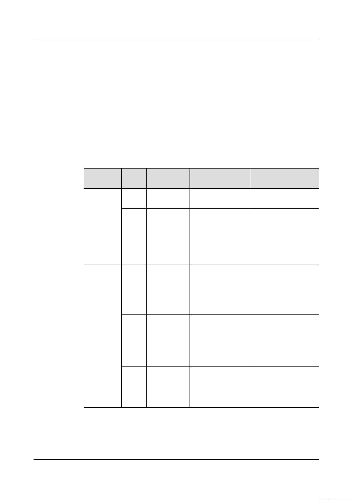
DBS3900 LampSite
Installation Guide
7.1 Information About the Installation
This section describes the information that you must be familiar with before installing a
pRRU3901, including the pRRU3901 product family, installation scenarios, installation space
and environment requirements.
7.1.1 Product Family
This chapter describes the configurations and functions of the pRRU3901 components.
Table 7-1 lists the pRRU3901 product family.
Table 7-1 pRRU3901 product family
7 Installing a pRRU3901
Category
Main
equipment
Auxiliary
device
Equip
ment
pRRU
Optional or
Mandatory
Mandatory 1 Processes the radio
3901
Extern
Optional 2 Provides external
al
antenn
a
Mounti
Mandatory 1 Supports the pRRU3901
ng kits
CabinetOptional
Quantity Function
frequency signals.
antennas for the
pRRU3901.
NOTE
Configure two external
antennas for each RF
daughter board.
installation on a wall,
pole, ceiling, or keel.
The mounting kits vary
with the pRRU3901
installation mode.
l None and one
Extender is
needed
Install the pRRU3901
and Extender in the
outdoor scenario.
l Yes and two
Extenders are
needed
ExtenderOptional 1 or 2
NOTE
The quantity depends
on the number of
Ethernet cables in use.
Issue 07 (2015-12-30) Huawei Proprietary and Confidential
Copyright © Huawei Technologies Co., Ltd.
Extends the distance
between the pRRU3901
and RHUB.
54
Page 62

DBS3900 LampSite
Installation Guide
7.1.2 Installation Scenario
The pRRU3901 can be installed on a wall, ceiling, pole, or keel. The following table describes
the installation in different scenarios.
Installing a pRRU3901 on a wall
NOTE
l The pRRU3901 must keep a minimum of 0.5 m away from the power equipment with interference,
and keep a minimum of 2 m away from the source with radiation.
l The pRRU3901 must keep away from a metal wall to avoid the impact on the antenna performance.
When a pRRU3901 is installed on a wall, installation modes vary with the quality of wall, as
shown in Table 7-2.
Table 7-2 Wall-mounted suggestion
7 Installing a pRRU3901
Installation
Mode
Installing the
pRRU3901 on
a wall by
drilling holes
For details, see
7.4.2
Installing a
pRRU3901 on
a Wall.
Installing the
pRRU on a
wall using a V
clamp through
an attachment
plate
For details, see
7.4.5
Installing a
pRRU3901 on
a Plate.
Requirements Mounting Brackets Installation
Diagram
l The wall can
bear a load at
least four times
the weight of a
pRRU3901.
l The screws must
1. Plate
2. Screw (M6X50)
3. Plastic expansion
sleeve
4. Flat washer
be tightened with
a torque of 10
N·m. This
ensures the
screws work
properly and the
wall remains
intact without
cracks in it.
l The wall can
bear a load at
least four times
the weight of a
1. Plate
2. V clamp
3. Bolt (M6X80)
pRRU3901.
l The thickness of
the wall is less
than 80 mm.
Issue 07 (2015-12-30) Huawei Proprietary and Confidential
Copyright © Huawei Technologies Co., Ltd.
55
Page 63

DBS3900 LampSite
Installation Guide
7 Installing a pRRU3901
Installation
Requirements Mounting Brackets Installation
Mode
Installing the
pRRU3901 on
a wall using a
plate on a
metal wall
The wall cannot bear
a load at least four
times the weight of
the pRRU. For
example, EPS walls,
MDF walls, or walls
cannot be drilled.
Installing a pRRU3901 on a ceiling
When a pRRU3901 is installed on a ceiling, installation modes vary with the quality of the
ceiling, as shown in Table 7-3.
Table 7-3 Ceiling-mounted suggestion
Installation
Mode
Requirements Mounting Brackets Installation
Diagram
The plate is prepared by
customers.
Diagram
Installing the
pRRU3901 on
a ceiling by
drilling holes
For details, see
7.4.3
Installing a
pRRU3901 on
a Ceiling.
l The ceiling, such
as a concrete
ceiling, can bear
a load at least
four times the
weight of the
pRRU3901.
l The screws must
be tightened with
a torque of 10
N·m. This
ensures the
screws work
properly and the
ceiling remains
intact without
cracks in it.
1. Plate
2. Screw (M6X50)
3. Plastic expansion
sleeve
4. Flat washer
Issue 07 (2015-12-30) Huawei Proprietary and Confidential
Copyright © Huawei Technologies Co., Ltd.
56
Page 64

DBS3900 LampSite
Installation Guide
7 Installing a pRRU3901
Installation
Mode
Installing the
pRRU3901 on
a ceiling using
a V clamp
through an
attachment
plate
For details, see
7.4.5
Installing a
pRRU3901 on
a Plate.
Installing the
pRRU3901 on
a pole
For details, see
7.4.4
Installing a
pRRU3901 on
a Pole.
Requirements Mounting Brackets Installation
Diagram
l The ceiling, such
as a concrete
ceiling, can bear
a load at least
1. Plate
2. V clamp
3. Bolt (M6X80)
four times the
weight of the
pRRU3901.
l The thickness of
the ceiling is less
than 80 mm.
A pole under the
ceiling can bear a
For details, see Table
7-4.
For details, see Table
7-4.
load at least four
times the weight of
the pRRU3901.
Installing the
pRRU3901 on
a keel
For details, see
7.4.6
A keel under the
ceiling can bear a
load at least four
times the weight of
the pRRU3901.
Installing a
pRRU3901 on
a Keel.
Installing the pRRU3901 on a pole
When a pRRU3901 is installed on a pole, installation modes vary with the diameter of the
pole, as shown in Table 7-4.
For details, see Table
7-5.
For details, see Table
7-5.
Issue 07 (2015-12-30) Huawei Proprietary and Confidential
Copyright © Huawei Technologies Co., Ltd.
57
Page 65

DBS3900 LampSite
Installation Guide
7 Installing a pRRU3901
Table 7-4 Pole-mounted suggestion
Installation
Mode
Installing the
pRRU3901 on
a pole
For details, see
7.4.4
Installing a
pRRU3901 on
a Pole.
Requirements Mounting Brackets Installation
Diagram
The diameter of the
pole ranges from 30
mm to 70 mm.
The diameter of the
pole ranges from 70
mm to 110 mm.
1. Plate
2. V clamp
3. Bolt (M6X80)
1. Plate
2. Hose clamp, which is
prepared by the
customer
Installing the pRRU3901 on a keel
The pRRU3901 can be installed on a keel of U-shape, T-shape, or H-shape. For the keels of
other shapes, they are determined based on the onsite requirements.
Table 7-5 Keel-mounted installation suggestion
Installation
Mode
Installing the
pRRU3901 on
a keel
For details, see
7.4.6
Installing a
pRRU3901 on
a Keel.
Requirements Mounting Brackets Installation
The keel is in Ushape, T-shape, Hshape, or other
shapes.
pRRU3901 cabinet
Diagram
1. Plate
2. V clamp
3. Bolt (M6X80)
shows the pRRU
installed on a Ushaped keel.
In the outdoor scenario, pRRU3901 should be installed in the cabinet.
Issue 07 (2015-12-30) Huawei Proprietary and Confidential
Copyright © Huawei Technologies Co., Ltd.
58
Page 66

DBS3900 LampSite
Installation Guide
7 Installing a pRRU3901
Table 7-6 Cabinet installation suggestion
Installation
RequirementsMounting Brackets Installation Diagram
Mode
Installing the
cabinet
For details,
see7.4.7
Installing the
Remove the
housing before
installing a
pRRU3901 in
the cabinet.
Cabinet
7.1.3 Space Requirements
This chapter describes the space requirements of the pRRU3901.
When the pRRU3901 is installed on a wall, ceiling, pole or keel, the minimum space is
required for easy cabling and O&M. Based on the engineering practice, the recommendation
for the installation space is provided.
1. Plate
NOTE
During installation, a minimum clearance of 2 m must be reserved between the pRRU3901 working on
the 2.6 GHz band and the Wi-Fi module if they need to process services concurrently.
Figure 7-1 shows the recommended space requirements of the pRRU3901.
Figure 7-1 Recommended space requirements of the pRRU3901
The recommended space for installing a single pRRU3901 is described as follows:
Issue 07 (2015-12-30) Huawei Proprietary and Confidential
Copyright © Huawei Technologies Co., Ltd.
59
Page 67

DBS3900 LampSite
Installation Guide
l At least 300 mm above the pRRU3901 is reserved for maintenance.
l At least 300 mm under the pRRU3901 is reserved for cabling.
l At least 300 mm on the left of the pRRU3901 is reserved for maintenance.
l At least 300 mm on the right of the pRRU3901 is reserved for maintenance.
l At least 400 mm in front of the pRRU3901 is reserved for maintenance
l At least 40 mm on the back of the pRRU3901 is reserved for ventilation.
In the outdoor scenario, there is no space requirement for the pRRU3901 installing in the
cabinet.
7.1.4 Installation Environment Requirements
The installation environment of a pRRU3901 involves the running environment specifications
for the pRRU3901 and other specifications.
Running Environment Specifications
Table 7-7 shows the environment specifications for the pRRU3901 installed indoors.
7 Installing a pRRU3901
Table 7-7 pRRU3901 environment specifications
Specificat
ions
Operating
temperatur
e
Relative
humidity
Altitude - 60 m to + 1800 m Works properly.
Condition Remarks
l Indoor: - 5 °C to + 40 °C
l Outdoor: - 20 °C to + 40 °C
5% RH to 95% RH -
1800 m to 4000 m Above the 1800 m altitude, the
Other Running Environment Specifications
l The pRRU3901 cannot be installed at an air outlet of the heat dissipation box of an air
conditioner or other heat-generating appliances.
l The pRRU3901 cannot be installed near a strong heat source.
l The pRRU3901 cannot be installed in a position with water dripping, such as outdoor
equipment of air conditioners, pipe, and leaking or dripping roofs.
l The installation position must be far from rains. If the pRRU3901 is installed on a wall,
there must be no window on either side of the wall.
l The installation position must be far away from high voltage, highly corrosive devices,
flammable or explosive substances, and electromagnetic interference such as power
stations, high-voltage substations, and wired TV towers.
-
maximum operating temperature
decreases by 1 °C each time the
altitude increases by 220 m.
Issue 07 (2015-12-30) Huawei Proprietary and Confidential
Copyright © Huawei Technologies Co., Ltd.
60
Page 68

DBS3900 LampSite
Installation Guide
l The pRRU3901 must be installed in a dry, ventilating, and dust-proof place.
l If the pRRU3901 is installed in parking areas or basements, the installation position must
be well-ventilated.
7.2 Obtaining the MAC Address (Optional)
Before installing a pRRU3901, record the media access control (MAC) address, which will be
used during pRRU3901 commissioning. This section applies only when a pRRU3901 with
three transmission ports is configured with a Wi-Fi daughter board.
Context
The MAC address indicates the IP address through which a device can be reached.
Procedure
Step 1 Remove the backup WIFI MAC label from the front housing of the pRRU3901 and keep
them secure, as shown in Figure 7-2.
7 Installing a pRRU3901
NOTE
l Do not remove the WIFI MAC label on the side of the pRRU3901 housing.
l Before removing the backup WIFI MAC label, photograph it.
Figure 7-2 Removing backup WIFI MAC label
Step 2 Save the MAC according to 14.1 MAC Collection Template, and report it to the pRRU3901
commissioning personnel.
----End
7.3 Installation Process
This section describes the pRRU3901 installation process, which involves installing a
pRRU3901, and cables, checking the pRRU3901 hardware installation, and powering on the
pRRU3901.
Figure 7-3 shows the pRRU3901 installation process.
Issue 07 (2015-12-30) Huawei Proprietary and Confidential
Copyright © Huawei Technologies Co., Ltd.
61
Page 69

DBS3900 LampSite
Installation Guide
7 Installing a pRRU3901
Figure 7-3 pRRU3901 installation process
7.4 Installing a pRRU3901
This section describes the pRRU3901 installation process. A pRRU3901 can be installed on a
wall, ceiling, indoor metal pole, or standard keel, but not on an aluminum panel or a nonstandard keel.
NOTE
Note the following when installing the pRRU3901:
l The pRRU3901 cannot be grounded. If the pRRU3901 is grounded but the RHUB connected to this
pRRU3901 is not, the pRRU3901 may fail to be powered on.
l A minimum distance of 50 cm must be reserved between the pRRU3901 and the incandescent lamp.
l The installation spacing between the pRRU3901 and the temperature sensor must be greater than 50
cm.
l It is good practice to install the pRRU3901 on materials that can tolerate a temperature higher than
65°C and have an ignition point higher than 70°C.
Issue 07 (2015-12-30) Huawei Proprietary and Confidential
Copyright © Huawei Technologies Co., Ltd.
62
Page 70

DBS3900 LampSite
Installation Guide
7.4.1 pRRU3901 Mounting Kits
This section describes the pRRU3901 mounting kits.
Figure 7-4 shows the exterior of the pRRU3901 mounting kits.
Figure 7-4 pRRU3901 mounting kits
7 Installing a pRRU3901
(1) V clamp (2) Mounting bracket (3) Screw (M6x50)
(4) Plastic expansion sleeve (5) Bolt (M6x80) (6) Flat washer
The following figure shows the specifications of the mounting bracket.
Figure 7-5 Mounting bracket specifications
Issue 07 (2015-12-30) Huawei Proprietary and Confidential
Copyright © Huawei Technologies Co., Ltd.
63
Page 71

DBS3900 LampSite
Installation Guide
7.4.2 Installing a pRRU3901 on a Wall
This section describes how to install a pRRU3901 on an indoor wall. If a wall indoors has
adequate load bearing capacity and installation space, it is good practice to install the
pRRU3901 on the wall. If the wall does not have adequate load bearing capacity, choose an
installation mode based on site requirements.
Context
NOTICE
This section describes only the wall-mounted installation in which mounting kits are directly
installed on the wall without auxiliary devices. The procedure for other wall-mounted
installation modes is similar.
Procedure
7 Installing a pRRU3901
Step 1 Determine the position for installing the pRRU3901 based on the construction blueprint and
the clearance requirements.
NOTE
For details about the clearance requirements, see 7.1.3 Space Requirements.
Step 2 Place the mounting bracket in the installation position against the wall. Then, level the
mounting bracket and use a marker to mark two anchor points. See Figure 7-6.
Figure 7-6 Anchor points on the pRRU3901 mounting bracket (unit: mm)
(1) Wall (2) Mounting bracket (3) Anchor point
Issue 07 (2015-12-30) Huawei Proprietary and Confidential
Copyright © Huawei Technologies Co., Ltd.
64
Page 72

DBS3900 LampSite
Installation Guide
Step 3 Use a hammer drill with φ8 bore to drill holes at the marked anchor points, as shown in
7 Installing a pRRU3901
CAUTION
To prevent inhalation or eye contact with dust, take adequate preventive measures when
drilling holes.
Figure 7-7. Use a vacuum cleaner to clean the dust inside and around the holes and measure
the distance between them. If they are inaccurately positioned, re-measure and re-drill the
holes. Then, use a rubber mallet to hit a plastic expansion sleeve into each hole.
Figure 7-7 Drilling holes and installing expansion bolts
Step 4 Lead the M6x50 screws through the washers, and then through the drilling holes on the
mounting bracket to the plastic expansion sleeves, and torque the screws to 5 N•m, as shown
in Figure 7-8.
Issue 07 (2015-12-30) Huawei Proprietary and Confidential
Copyright © Huawei Technologies Co., Ltd.
65
Page 73

DBS3900 LampSite
Installation Guide
7 Installing a pRRU3901
Figure 7-8 Installing the mounting bracket
NOTE
If the screws cannot be tightened using a Phillips screwdriver, use a hex key or an electric screwdriver to
assist the installation.
Step 5 Fit the four hooks of the pRRU3901 into the mounting holes on the mounting bracket and
then press the pRRU3901 downwards until a click is heard. See Figure 7-9.
NOTE
It is good practice to perform the installation from the side view to promptly align the hooks with the
mounting holes.
Issue 07 (2015-12-30) Huawei Proprietary and Confidential
Copyright © Huawei Technologies Co., Ltd.
66
Page 74

DBS3900 LampSite
Installation Guide
7 Installing a pRRU3901
Figure 7-9 Installing the pRRU3901 on a wall
----End
7.4.3 Installing a pRRU3901 on a Ceiling
This section describes how to install a pRRU3901 on the ceiling, such as the concrete ceiling,
when the ceiling has adequate load bearing capacity and installation space.
Context
NOTICE
If the pRRU3901 is installed on a ceiling, the temperature of the ceiling may increase by a
maximum of 30 degrees. Therefore, whether a pRRU3901 can be installed on a ceiling
depends on the ceiling material.
Procedure
Step 1 Determine the position for installing the pRRU3901 based on the construction blueprint and
the clearance requirements.
Issue 07 (2015-12-30) Huawei Proprietary and Confidential
Copyright © Huawei Technologies Co., Ltd.
67
Page 75

DBS3900 LampSite
Installation Guide
Step 2 Place the mounting bracket in the installation position against the ceiling. Then, level the
7 Installing a pRRU3901
NOTE
For details about the clearance requirements, see 7.1.3 Space Requirements.
mounting bracket and use a marker to mark two anchor points. See Figure 7-10.
Figure 7-10 Anchor points on the pRRU3901 mounting bracket (unit: mm)
(1) Ceiling (2) Mounting bracket (3) Anchor point
CAUTION
To prevent inhalation or eye contact with dust, take adequate preventive measures when
drilling holes.
Step 3 Use a hammer drill with φ8 bore to drill holes at the marked anchor points, as shown in
Figure 7-11. Use a vacuum cleaner to clean the dust inside and around the holes and measure
the distance between them. If they are inaccurately positioned, re-measure and re-drill the
holes. Then, use a rubber mallet to hit a plastic expansion sleeve into each hole.
Issue 07 (2015-12-30) Huawei Proprietary and Confidential
Copyright © Huawei Technologies Co., Ltd.
68
Page 76

DBS3900 LampSite
Installation Guide
Step 4 Lead the M6x50 screws through the washers, and then through the drilling holes on the
7 Installing a pRRU3901
Figure 7-11 Drilling holes and installing expansion bolts
mounting bracket to the plastic expansion sleeves, and use a torque screwdriver to torque the
screws to 5 N•m, as shown in Figure 7-12.
Figure 7-12 Installing the mounting bracket
NOTE
If the screws cannot be tightened using a Phillips screwdriver, use a hex key or an electric screwdriver to
assist the installation.
Step 5 Fit the four hooks of the pRRU3901 into the mounting holes on the mounting bracket and
then press the pRRU3901 downwards until a click is heard. See Figure 7-13.
NOTE
It is good practice to perform the installation from the side view to promptly align the hooks with the
mounting holes.
Issue 07 (2015-12-30) Huawei Proprietary and Confidential
Copyright © Huawei Technologies Co., Ltd.
69
Page 77

DBS3900 LampSite
Installation Guide
7 Installing a pRRU3901
Figure 7-13 Installing a pRRU3901 on a ceiling
----End
7.4.4 Installing a pRRU3901 on a Pole
This section describes how to install a pRRU3901 on a metal pole indoors.
Procedure
Step 1 Determine the position for installing the pRRU3901 based on the construction blueprint and
the clearance requirements.
NOTE
For details about the clearance requirements, see 7.1.3 Space Requirements.
Step 2 If the diameter of the pole ranges from 30 mm to 70 mm, use the delivered V clamp,
mounting bracket, and bolts to install the pRRU3901 on the pole. Lead the M6x80 bolts
through the mounting bracket, and torque the bolts to 5 N•m, as shown in Figure 7-14.
Issue 07 (2015-12-30) Huawei Proprietary and Confidential
Copyright © Huawei Technologies Co., Ltd.
70
Page 78

DBS3900 LampSite
Installation Guide
7 Installing a pRRU3901
Figure 7-14 Securing the pRRU3901 mounting bracket on the metal pole
If the diameter of the pole is greater than 70 mm, use the hose clamp to install the mounting
bracket on the pole. The hose clamp is prepared by customers. Torque the bolts to 5 N•m, as
shown in Figure 7-15.
Figure 7-15 Securing the pRRU3901 mounting bracket on the metal pole
Issue 07 (2015-12-30) Huawei Proprietary and Confidential
Copyright © Huawei Technologies Co., Ltd.
71
Page 79

DBS3900 LampSite
Installation Guide
Step 3 Fit the four hooks of the pRRU3901 into the mounting holes on the mounting bracket and
7 Installing a pRRU3901
then press the pRRU3901 downwards until a click is heard. See Figure 7-16.
NOTE
It is good practice to perform the installation from the side view to promptly align the hooks with the
mounting holes.
Figure 7-16 Installing a pRRU3901 on a pole
----End
7.4.5 Installing a pRRU3901 on a Plate
This section describes how to install a pRRU3901 on a plate. If a suspended ceiling plate has
adequate load bearing capacity and installation space, the pRRU3901 can be installed on the
plate. However, it is good practice not to install a pRRU3901 on an aluminum plate.
Procedure
Step 1 Determine the position for installing the pRRU3901 based on the construction blueprint and
the clearance requirements.
NOTE
For details about the clearance requirements, see 7.1.3 Space Requirements.
Step 2 Place the mounting bracket in the installation position against the wall. Then, level the
mounting bracket and use a marker to mark two anchor points. See Figure 7-17.
Issue 07 (2015-12-30) Huawei Proprietary and Confidential
Copyright © Huawei Technologies Co., Ltd.
72
Page 80

DBS3900 LampSite
Installation Guide
7 Installing a pRRU3901
Figure 7-17 Anchor points on the pRRU3901 mounting bracket (unit: mm)
(1) Plate (2) Mounting bracket (3) Anchor point
CAUTION
To prevent inhalation or eye contact with dust, take adequate preventive measures when
drilling holes.
Step 3 Use a hammer drill with φ8 bore to drill holes at the anchor points.
Step 4 Lead the M6x80 bolts through the mounting bracket and the ceiling plate, and use a torque
screwdriver to torque the bolts to 5 N•m, as shown in Figure 7-18.
Issue 07 (2015-12-30) Huawei Proprietary and Confidential
Copyright © Huawei Technologies Co., Ltd.
73
Page 81

DBS3900 LampSite
Installation Guide
7 Installing a pRRU3901
Figure 7-18 Installing the pRRU3901 mounting bracket
Step 5 Fit the four hooks of the pRRU3901 into the mounting holes on the mounting bracket and
then press the pRRU3901 downwards until a click is heard. See Figure 7-19.
NOTE
It is good practice to perform the installation from the side view to promptly align the hooks with the
mounting holes.
Issue 07 (2015-12-30) Huawei Proprietary and Confidential
Copyright © Huawei Technologies Co., Ltd.
74
Page 82

DBS3900 LampSite
Installation Guide
7 Installing a pRRU3901
Figure 7-19 Installing a pRRU3901 on a plate
----End
7.4.6 Installing a pRRU3901 on a Keel
This section describes how to install a pRRU3901 on a keel. If a suspended ceiling plate
cannot bear the pRRU3901, the pRRU3901 can be installed on the keel on the ceiling.
Context
Before installing the pRRU3901 on a keel, ensure that the keel is strong enough to bear the
pRRU3901.
l The mounting bracket of the pRRU3901 can be installed on the keel of the following
specifications: GBT 11981-2008, JIS A6517-2002, and ASTM C635 C635M-2007. The
installation mode depends on onsite requirements because there are various keels.
l This section describes the procedure of installing a pRRU3901 on the keel of JIS
standard used in Japan. The procedure of installing a pRRU3901 on other keels is the
same as that of installing a pRRU3901 on the keel of JIS standard.
Procedure
Step 1 Determine the position for installing the pRRU3901 based on the construction blueprint and
the clearance requirements.
NOTE
For details about the clearance requirements, see 7.1.3 Space Requirements.
Step 2 Place the V clamp across the keel, and use a marker to mark the projective positions of the
mounting holes on the suspended ceiling plate, as shown in Figure 7-20.
Issue 07 (2015-12-30) Huawei Proprietary and Confidential
Copyright © Huawei Technologies Co., Ltd.
75
Page 83
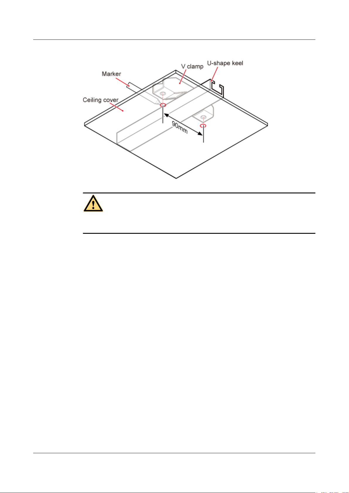
DBS3900 LampSite
Installation Guide
7 Installing a pRRU3901
Figure 7-20 Anchor points on the suspended ceiling plate (unit: mm)
CAUTION
To prevent inhalation or eye contact with dust, take adequate preventive measures when
drilling holes.
Step 3 Use a hammer drill to drill holes at the anchor points. You are advised to use the hammer drill
with Ф12 bore.
Step 4 Lead the M6x80 bolts through the mounting bracket and the suspended ceiling plate. Use a
torque screwdriver to torque the bolts to 5 N•m, as shown in Figure 7-21.
Issue 07 (2015-12-30) Huawei Proprietary and Confidential
Copyright © Huawei Technologies Co., Ltd.
76
Page 84

DBS3900 LampSite
Installation Guide
7 Installing a pRRU3901
Figure 7-21 Installing the pRRU3901 mounting bracket
Step 5 Fit the four hooks of the pRRU3901 into the mounting holes on the mounting bracket and
then press the pRRU3901 downwards until a click is heard. See Figure 7-22.
NOTE
It is good practice to perform the installation from the side view to promptly align the hooks with the
mounting holes.
Issue 07 (2015-12-30) Huawei Proprietary and Confidential
Copyright © Huawei Technologies Co., Ltd.
77
Page 85

DBS3900 LampSite
Installation Guide
7 Installing a pRRU3901
Figure 7-22 Installing a pRRU3901 on a keel
----End
7.4.7 Installing the Cabinet
In the outdoor scenario, the pRRU3901 should be installed in the cabinet firstly.
Context
l When installed in the cabinet, the housing of pRRU3901 should be removed.
l An RF surge protector provides surge protection for the RF ports on pRRU3902, and a
PoE surge protector provides surge protection for the CPRI ports.
l One pRRU3901 with internal antenna need to be configured with one or two PoE surge
protectors.
l One pRRU3901 with external antenna need to be configured with one PoE surge
protector, or two RF surge protectors when one RF daughter board is configured, or four
RF surge protectors when two RF daughter boards are configured.
Procedure
Step 1 Remove the housing on the top and at the bottom of pRRU3901, as shown in Figure 7-23.
Issue 07 (2015-12-30) Huawei Proprietary and Confidential
Copyright © Huawei Technologies Co., Ltd.
78
Page 86

DBS3900 LampSite
Installation Guide
7 Installing a pRRU3901
Figure 7-23 Removing the housing of pRRU3901
1. Use the M4 Phillips screwdriver to loosen the Phillips screw on the pRRU housing.
Wrench and remove the housing from the installation position of the Phillips screw hole,
as shown in Figure 7-24.
Figure 7-24 Removing the pRRU housing
Issue 07 (2015-12-30) Huawei Proprietary and Confidential
Copyright © Huawei Technologies Co., Ltd.
79
Page 87

DBS3900 LampSite
Installation Guide
7 Installing a pRRU3901
NOTE
– The pRRU housing and the RF daughter board can be secured using either Phillips screws or
protection screws, requiring the same installation operations. This section uses Phillips screws
as an example to describe the installation operations.
– Keep the Phillips screw secure for future use.
2. Use the M4 Phillips screwdriver to loosen the Phillips screws on the RF daughter board,
as shown in Figure 7-25.
Figure 7-25 Loosen the Phillips screws
3. Use the left hand to hold the RF daughter board and the right hand to hold the right
handle of the RF daughter board to remove the RF daughter board and put it into an ESD
box or bag, as shown in Figure 7-26.
Issue 07 (2015-12-30) Huawei Proprietary and Confidential
Copyright © Huawei Technologies Co., Ltd.
80
Page 88

DBS3900 LampSite
Installation Guide
7 Installing a pRRU3901
Figure 7-26 Removing the RF daughter board in slot1
4. Use an M3 Phillips screwdriver to loosen the two fastening screws of the light pipe, and
remove the light pipe, as shown in Figure 7-27.
Figure 7-27 Removing the light pipe
5. Use the M3 Phillips screwdriver to loosen the four fastening screws of the pDock mother
board, and remove the pDock mother board, as shown in Figure 7-28.
Issue 07 (2015-12-30) Huawei Proprietary and Confidential
Copyright © Huawei Technologies Co., Ltd.
81
Page 89

DBS3900 LampSite
Installation Guide
7 Installing a pRRU3901
Figure 7-28 Removing the pDock mother board
6. Install the RF daughter boards in slots S1, and use the M4 Phillips screwdriver to tighten
the two fastening screws always carried on each daughter board to 1.4 N•m, as shown in
Figure 7-29.
Figure 7-29 Installing the RF daughter boards
NOTICE
The installation positions of the RF daughter boards must be consistent before and after
the replacement.
Issue 07 (2015-12-30) Huawei Proprietary and Confidential
Copyright © Huawei Technologies Co., Ltd.
82
Page 90

DBS3900 LampSite
Installation Guide
Step 2 Install the plate onto the cabinet, as shown in Figure 7-30.
7 Installing a pRRU3901
Figure 7-30 Installing the plate onto the cabinet
Issue 07 (2015-12-30) Huawei Proprietary and Confidential
Copyright © Huawei Technologies Co., Ltd.
83
Page 91

DBS3900 LampSite
Installation Guide
7 Installing a pRRU3901
NOTICE
Make sure all the cables are installed before installing the plate. For details about installing
the cables of pRRU3901, see Figure 7-31.
Figure 7-31 Installing the pRRU3901 cables
(1) RF Jumper (2) CPRI_E0 port (3) Ethernet Cable
Step 3 Fit the four hooks on pRRU3901 into the hooks on the mounting bracket, and then push
pRRU3901 down against the mounting bracket until a click is heard, as shown in Figure
7-32.
Issue 07 (2015-12-30) Huawei Proprietary and Confidential
Copyright © Huawei Technologies Co., Ltd.
84
Page 92

DBS3900 LampSite
Installation Guide
7 Installing a pRRU3901
Figure 7-32 Installing a pRRU3901 into the cabinet
----End
7.5 Installing pRRU3901 Cables
This section describes the procedure of installing the pRRU3901 cables.
7.5.1 Requirements for Cable Layout
Cables must be routed according to the specified cabling requirements to prevent signal
interference.
NOTE
If certain cables listed below are not required, skip the requirements for routing these cables.
General Requirements for Cable Layout
National Standards
l Code for Engineering Design of Generic Cabling System for Building and Campus (GB
50311-2007)
l Code for Engineering Acceptance of Generic Cabling System for Building and Campus
(GB50312-2007).
l Security Protection Engineering Technology Specifications (GB 50348-2004)
l Code for Construction and Acceptance of the Electronic Information System Room (GB
50462-2008)
l Code for Quality Acceptance of the Intelligent Building Engineering (GB 50339-2003)
l Code for Quality Acceptance of Electric Engineering Construction in Building (GB
50303-2002)
Issue 07 (2015-12-30) Huawei Proprietary and Confidential
Copyright © Huawei Technologies Co., Ltd.
85
Page 93

DBS3900 LampSite
Installation Guide
7 Installing a pRRU3901
l Technical Specification for Construction and Acceptance of Telecommunication Conduit
Engineering (GB 50374-2006)
International Standards
l Generic Cabling for Customer Premises (ISO/IEC 11801)
l Commercial Building Telecommunications Cabling Standard (EIA/TIA 568)
l Commercial Building Standard for Telecommunication Pathways and Spaces (EIA/TIA
569)
l Administration Standard for Commercial Telecommunications Infrastructure (EIA/TIA
606)
l Grounding and Bonding Requirements for Telecommunications in Commercial
Buildings (EIA/TIA 607)
l Generic Cabling Systems for Information Technology (EN 50173)
l Cabling Installation for Information Technology (EN 50174)
Bending radius
l The bending radius of a 1/4'' jumper, a 1/2'' softer jumper, and a 1/2'' common jumper
must be longer than 35 mm, 50 mm, and 127 mm, respectively.
l The bending radius of a power cable is at least three times the diameter of the cable.
l The bending radius of a signal cable must be at least five times of the diameter of the
cable.
Cable binding
l Cables of the same type are bound together.
l Different types of cables must be separately routed with a minimum spacing of 30 mm
and cannot be entangled.
l The cables are bound tightly and neatly and the sheaths of the cables is intact.
l The cable ties face the same direction and all cable ties bound at similar positions must
be in a straight line.
l The extra length of each indoor cable tie must be cut off. A slack of 5 mm is reserved for
each outdoor cable tie before the extra length is cut off. All cut surfaces are without
sharp edges.
l Labels or nameplates are attached to both ends, joints, or turns of cables after they are
installed.
Safety
l The steel pipe or fire-resistant rigid polyvinyl chloride pipe should be used for the cable
duct or for routing cables. The cross-sectional usage of the cable duct should be 30% to
50% and that of the pipe for routing cables should be 25% to 30%.
l Cables are placed away from sharp objects or wall burrs. If these positions are inevitable,
protection pipes are required for the cables.
l Cables are routed away from heat sources, or heat-insulation materials are added
between cables and heat sources.
l A clearance is reserved at turns of a cable or the position close to a device, facilitating
cable and device maintenance. The recommended clearance is about 0.1 m.
Requirements for Special Cables
Ethernet Cable
Issue 07 (2015-12-30) Huawei Proprietary and Confidential
Copyright © Huawei Technologies Co., Ltd.
86
Page 94
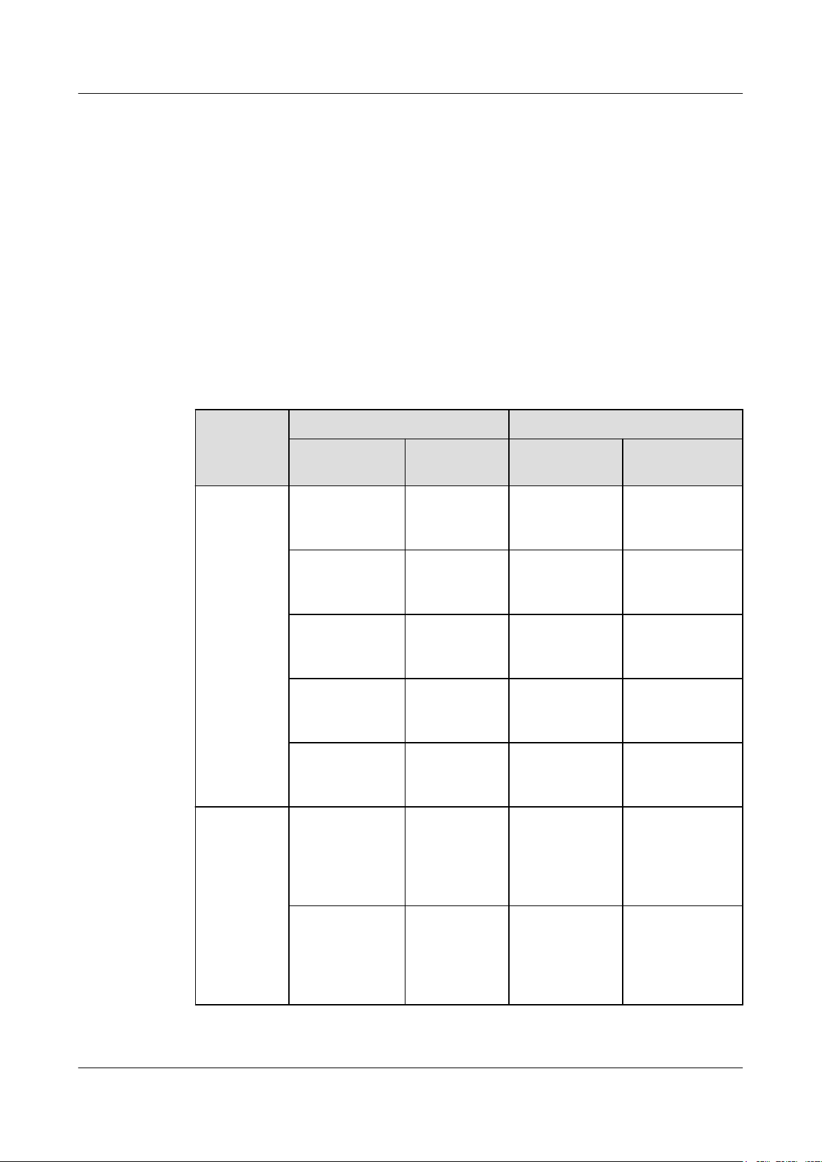
DBS3900 LampSite
Installation Guide
l A maximum of 100 Ethernet cables can be bundled if no PVC pipes are used. If pipes are
used, a maximum of 24 Ethernet cables can be led through a pipe. In this case, ensure
that 1/3 space inside the pipes must be vacant.
l The point at which an Ethernet cable is bundled must be spaced 400 mm or less from the
Ethernet port on a pRRU.
l For the pRRU3901 used in the elevator engine room on the rooftop, generator set for the
subway engine, and equipment room with central air conditioning, Ethernet cables must
be led through metallic conduits that are reliably grounded at both ends.
7.5.2 pRRU3901 Cable List
This section describes pRRU3901 cable connections.
Table 7-8 lists pRRU3901 cables.
Table 7-8 List of pRRU3901 cables
7 Installing a pRRU3901
Cable
Ethernet
Cable
(Optional)
RF Jumper
One End The Other End
Connector Connected
to ...
RJ45 connector CPRI_E0~CP
RI_E7 port on
RHUB
RJ45 connector Transmission
port on Access
Control(AC)
RJ45 connector CPRI_E0~CP
RI_E7 port on
RHUB
RJ45 connector Surge port on
PoE surge
protector 2
RJ45 connector Protect port on
PoE surge
protector 1
SMA straight
male connector
External
antenna
TX/RX RF
port on
pRRU3901
Connector Connected to ...
RJ45 connector CPRI_E0~CPRI_
RJ45 connector GE port on
RJ45 connector Protect port on
RJ45 connector Surge port on
RJ45 connector CPRI_E0~CPRI_
Based on the
port model of
the antenna
system.
E1 port on
pRRU3901
pRRU3901
PoE surge
protector 2
PoE surge
protector 1
E1 port on
pRRU3901
Antenna system
SMA straight
male connector
Issue 07 (2015-12-30) Huawei Proprietary and Confidential
Copyright © Huawei Technologies Co., Ltd.
External
antenna
TX/RX RF
port on
pRRU3901
SMA straight
male connector
Protect port on
RF surge
protector
87
Page 95

DBS3900 LampSite
Installation Guide
7 Installing a pRRU3901
Cable One End The Other End
Connector Connected
SMA straight
male connector
NOTE
When the RHUB and the pRRU3901 connected using the Ethernet cable. If the Extender is used,
l In the indoor scenario, the Ethernet cable is divided into two parts, one between the RHUB and the
Extender and the other between the Extender and the pRRU3901.
l In the outdoor scenario, the Ethernet cable is divided into two parts, one among RHUB-PoE surge
protector 2- PoE surge protector 3-Extender and the other among the Extender- PoE surge
protector 4- PoE surge protector 1-pRRU3901.
7.5.3 Cable Connections (Indoor)
This section describes the cable connections for a single pRRU3901 and multiple pRRU3901s
in UMTS, LTE FDD, UMTS+LTE FDD, LTE FDD+LTE FDD mode.
Before installing the pRRU3901 cables, you must be aware of the following information:
l The pRRU3901 can obtain power supply through the power over Ethernet (PoE).
l For external antennas corresponding to RF daughter board 1, the TX port and RX port
are ANT0 and ANT1, respectively. For external antennas corresponding to RF daughter
board 2, the TX port and RX port are ANT2 and ANT3, respectively. For external
antennas corresponding to RF daughter board 3, the TX port and RX port are ANT4 and
ANT5, respectively.
l The external antenna system is optional, and the pRRU3901 jumpers are not delivered.
By default, the pRRU3901s are configured with built-in antennas. If the external antenna
system is connected, the antenna system automatically switches to the external one. One
end of the pRRU3901 RF jumper is the SMA male connector, which is connected to the
external antenna TX/RX RF port on the pRRU3901. The other end of the pRRU3901 RF
jumper is the type N male connector, which is connected to the antenna system. For the
standard of the pRRU3901 RF jumper, see (Optional) RF Jumper of the DBS3900
LampSite Hardware Description.
to ...
Surge port on
RF surge
protector
Connector Connected to ...
Based on the
Antenna system
port model of
the antenna
system.
Figure 7-33 shows the cable connection when the pRRU3901 is configured with only one RF
Daughter Board.
Issue 07 (2015-12-30) Huawei Proprietary and Confidential
Copyright © Huawei Technologies Co., Ltd.
88
Page 96

DBS3900 LampSite
Installation Guide
7 Installing a pRRU3901
Figure 7-33 pRRU3901 cable connection (1)
(1) Ethernet cable (2) RF jumper
NOTE
l The Extender can be used to lengthen the distance between the RHUB and the pRRU3901 connected
using the Ethernet cable. If the Extender is used, the Ethernet cable is divided into two parts, one
between the RHUB and the Extender and the other between the Extender and the pRRU3901.
l When two Ethernet cables are used to transmit CPRI signals, connect one end of the cables to the
CPRI_E0 and CPRI_E1 ports on the pRRU panel and the other end to any two ports of CPRI_E0 to
CPRI_E7 on the RHUB panel. On the RHUB panel, CPRI_E0 and CPRI_E1, CPRI_E2 and
CPRI_E3, CPRI_E4 and CPRI_E5, and CPRI_E6 and CPRI_E7 are used in pairs. CPRI_E0 on the
pRRU panel connects to the even-numbered CPRI port (for example, CPRI_E0, CPRI_E2,
CPRI_E4, or CPRI_E6) on the RHUB panel, and CPRI_E1 on the pRRU panel connects to the oddnumbered CPRI port (for example, CPRI_E1, CPRI_E3, CPRI_E5, or CPRI_E7). This document
describes signal transmission using one Ethernet cable as an example.
Figure 7-34 shows the cable connection when the pRRU3901 is configured with two RF
Daughter Boards.
Issue 07 (2015-12-30) Huawei Proprietary and Confidential
Copyright © Huawei Technologies Co., Ltd.
89
Page 97

DBS3900 LampSite
Installation Guide
7 Installing a pRRU3901
Figure 7-34 pRRU3901 cable connection (2)
(1) Ethernet cable (2) RF jumper
NOTE
l The Extender can be used to lengthen the distance between the RHUB and the pRRU3901 connected
using the Ethernet cable. If the Extender is used, the Ethernet cable is divided into two parts, one
between the RHUB and the Extender and the other between the Extender and the pRRU3901.
l When two Ethernet cables are used to transmit CPRI signals, connect one end of the cables to the
CPRI_E0 and CPRI_E1 ports on the pRRU panel and the other end to any two ports of CPRI_E0 to
CPRI_E7 on the RHUB panel. On the RHUB panel, CPRI_E0 and CPRI_E1, CPRI_E2 and
CPRI_E3, CPRI_E4 and CPRI_E5, and CPRI_E6 and CPRI_E7 are used in pairs. CPRI_E0 on the
pRRU panel connects to the even-numbered CPRI port (for example, CPRI_E0, CPRI_E2,
CPRI_E4, or CPRI_E6) on the RHUB panel, and CPRI_E1 on the pRRU panel connects to the oddnumbered CPRI port (for example, CPRI_E1, CPRI_E3, CPRI_E5, or CPRI_E7). This document
describes signal transmission using one Ethernet cable as an example.
Figure 7-34 shows the cable connection when the pRRU3901 is configured with two RF
Daughter Boards and one Wi-Fi daughter board.
Issue 07 (2015-12-30) Huawei Proprietary and Confidential
Copyright © Huawei Technologies Co., Ltd.
90
Page 98
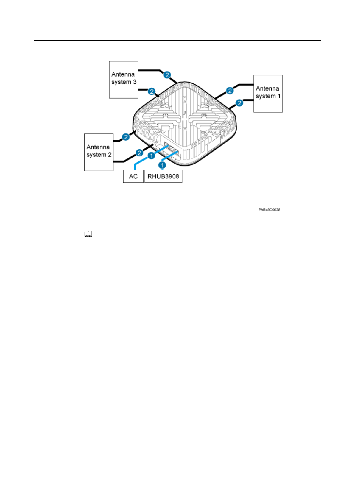
DBS3900 LampSite
Installation Guide
7 Installing a pRRU3901
Figure 7-35 pRRU3901 cable connection (3)
(1) Ethernet cable (2) RF jumper
NOTE
l The Extender can be used to lengthen the distance between the RHUB and the pRRU3901 connected
using the Ethernet cable. If the Extender is used, the Ethernet cable is divided into two parts, one
between the RHUB and the Extender and the other between the Extender and the pRRU3901.
l When two Ethernet cables are used to transmit CPRI signals, connect one end of the cables to the
CPRI_E0 and CPRI_E1 ports on the pRRU panel and the other end to any two ports of CPRI_E0 to
CPRI_E7 on the RHUB panel. On the RHUB panel, CPRI_E0 and CPRI_E1, CPRI_E2 and
CPRI_E3, CPRI_E4 and CPRI_E5, and CPRI_E6 and CPRI_E7 are used in pairs. CPRI_E0 on the
pRRU panel connects to the even-numbered CPRI port (for example, CPRI_E0, CPRI_E2,
CPRI_E4, or CPRI_E6) on the RHUB panel, and CPRI_E1 on the pRRU panel connects to the oddnumbered CPRI port (for example, CPRI_E1, CPRI_E3, CPRI_E5, or CPRI_E7). This document
describes signal transmission using one Ethernet cable as an example.
7.5.4 Cable Connections (Outdoor)
This section describes the cable connections for a pRRU3901 installed outside.
Before installing the pRRU3901 cables, you must be aware of the following information:
l The pRRU3901 can obtain power supply through the power over Ethernet (PoE).
l For external antennas corresponding to RF daughter board 1, the TX port and RX port
are ANT0 and ANT1, respectively. For external antennas corresponding to RF daughter
board 2, the TX port and RX port are ANT2 and ANT3, respectively. For external
antennas corresponding to RF daughter board 3, the TX port and RX port are ANT4 and
ANT5, respectively.
l The external antenna system is optional, and the pRRU3901 jumpers are not delivered.
By default, the pRRU3901s are configured with built-in antennas. If the external antenna
system is connected, the antenna system automatically switches to the external one. One
end of the pRRU3901 RF jumper is the SMA male connector, which is connected to the
external antenna TX/RX RF port on the pRRU3901. The other end of the pRRU3901 RF
Issue 07 (2015-12-30) Huawei Proprietary and Confidential
Copyright © Huawei Technologies Co., Ltd.
91
Page 99

DBS3900 LampSite
Installation Guide
7 Installing a pRRU3901
jumper is the type N male connector, which is connected to the antenna system. For the
standard of the pRRU3901 RF jumper, see (Optional) RF Jumper of the DBS3900
LampSite Hardware Description.
pRRU3901 can be configured with one RF daughter board, or two RF daughter boards, or two
RF daughter boards and one WiFi daughter board. Figure 7-36 shows the cable connection
when the pRRU3901 is configured with only one RF Daughter Board in the outside scenario.
Figure 7-36 pRRU3901 cable connection
(1) PoE surge protector 1 (2) pRRU3901 (3) RF surge protector
NOTE
l When two Ethernet cables are used to transmit CPRI signals, connect one end of the cables to the
CPRI_E0 and CPRI_E1 ports on the pRRU panel and the other end to any two ports of CPRI_E0 to
CPRI_E7 on the RHUB panel. On the RHUB panel, CPRI_E0 and CPRI_E1, CPRI_E2 and
CPRI_E3, CPRI_E4 and CPRI_E5, and CPRI_E6 and CPRI_E7 are used in pairs. CPRI_E0 on the
pRRU panel connects to the even-numbered CPRI port (for example, CPRI_E0, CPRI_E2,
CPRI_E4, or CPRI_E6) on the RHUB panel, and CPRI_E1 on the pRRU panel connects to the oddnumbered CPRI port (for example, CPRI_E1, CPRI_E3, CPRI_E5, or CPRI_E7). This document
describes signal transmission using one Ethernet cable as an example.
l The Extender can be used to lengthen the distance between the RHUB and the pRRU3901 connected
using the Ethernet cable. If the Extender is used, the Ethernet cable is divided into two parts, one
among the RHUB, PoE surge protector 2, PoE surge protector 3, Extender and the other among
Extender, PoE surge protector 4, PoE surge protector 1, pRRU3901.
l For details about installation of the PoE surge protector and cables, see 10 (Optional) Installing the
PoE Surge Protector and Cables.
l For details about installation of the RF surge protector and cables, see 11 (Optional) Installing the
RF Surge Protector and Cables.
7.5.5 Cable Connections (LTE TDD)
This section describes the cable connections for a single pRRU3901 and multiple pRRU3901s
in LTE TDD mode.
Before installing the pRRU3901 cables, you must be aware of the following information:
Issue 07 (2015-12-30) Huawei Proprietary and Confidential
Copyright © Huawei Technologies Co., Ltd.
92
Page 100

DBS3900 LampSite
Installation Guide
7 Installing a pRRU3901
l The pRRU3901 can obtain power supply through the power over Ethernet (PoE).
l For external antennas corresponding to RF daughter board 1, the TX port and RX port
are ANT0 and ANT1, respectively. For external antennas corresponding to RF daughter
board 2, the TX port and RX port are ANT2 and ANT3, respectively. For external
antennas corresponding to RF daughter board 3, the TX port and RX port are ANT4 and
ANT5, respectively.
l The external antenna system is optional, and the pRRU3901 jumpers are not delivered.
By default, the pRRU3901s are configured with built-in antennas. If the external antenna
system is connected, the antenna system automatically switches to the external one. One
end of the pRRU3901 RF jumper is the SMA male connector, which is connected to the
external antenna TX/RX RF port on the pRRU3901. The other end of the pRRU3901 RF
jumper is the type N male connector, which is connected to the antenna system. For the
standard of the pRRU3901 RF jumper, please see (Optional) RF Jumper of the DBS3900
LampSite Hardware Description.
Figure 7-37 shows the cable connection when the pRRU3901 is configured with only one RF
Daughter Board.
Figure 7-37 pRRU3901 cable connection (1)
(1) Ethernet cable (2) RF jumper
NOTE
The Extender can be used to lengthen the distance between the RHUB and the pRRU connected using
the Ethernet cable. If the Extender is used, the Ethernet cable is divided into two parts, one between the
RHUB and the Extender and the other between the Extender and the pRRU.
Figure 7-38 shows the cable connection when the pRRU3901 is configured with one RF
Daughter Boards and one Wi-Fi daughter board.
Issue 07 (2015-12-30) Huawei Proprietary and Confidential
Copyright © Huawei Technologies Co., Ltd.
93
 Loading...