

Huawei PowerCube 500 PC500-300H1, PowerCube 500 PC500-300G1 Quick Manual
PowerCube 500 V200R001C10 Quick Guide
Lithium
Battery
Indicator
Color
Status
Meaning
Run
indicator
(RUN)
Green
Off
The lithium battery has no power input
or is faulty.
Steady on
The lithium battery is powered on.
Blinking
slowly
(0.5 Hz)
The lithium battery is communicating
properly with upstream monitoring
equipment.
Blinking
fast (4 Hz)
The lithium battery fails to
communicate with upstream
monitoring equipment.
Alarm
indicator
(ALM)
Red
Off
There is no alarm.
Steady on
The lithium battery has generated a
fault alarm and needs to be replaced.
Blinking
slowly
(0.5 Hz)
The lithium battery has generated a
protection alarm, which can be cleared.
Function
Module
Indicator
Color
Status
Meaning
Run
indicator
Green
Off
The function module has no power input
or is faulty.
Blinking
slowly
(0.5 Hz)
The function module is communicating
properly with upstream monitoring
equipment.
Blinking
fast (4
Hz)
The function module fails to
communicate with upstream monitoring
equipment.
Alarm
indicator
Yellow
Off
There is no alarm.
Blinking
slowly
The function module has generated an
alarm, which can be cleared.
Steady
on
The function module has generated an
AC power failure or PV array fault alarm,
which can be cleared.
Fault
indicator
Red
Off
The function module is normal.
Blinking
slowly
The function module has an external
fault, which can be cleared.
Steady
on
The function module has an internal fault,
which cannot be cleared.
NOTE
(PC500-300H1, PC500-300G1)
Issue: 03
Date: 2018-03-22
Copyright © Huawei Technologies Co., Ltd. 2018. All rights reserved.
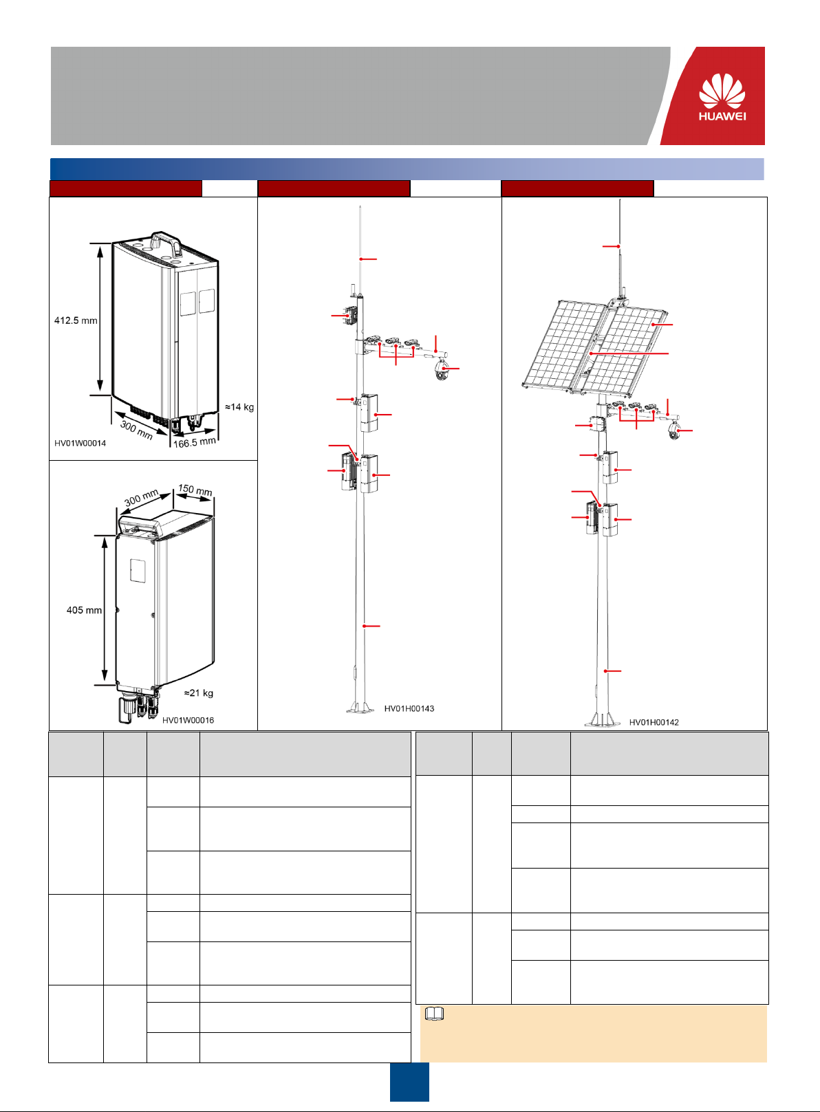
Overview
1
Appearance Grid Hybrid Scenario Solar Hybrid Scenario
Function module: PC500-300H1,
PC500-300G1
PMP
microwave
Lightning rod
Lightning rod
Cantilever
PV modules
Lithium battery: CBM20E-N14A1
Pole
mounting kit
Pole
mounting kit
Function
module
Bullet
cameras
Lithium battery
Lithium battery
Pole
Dome
camera
PMP
microwave
Pole
mounting kit
Pole
mounting kit
Function
module
Cantilever
Bullet
cameras
Lithium battery
Lithium battery
Pole
PV module
support
Dome camera
The three indicators are steady on when the power unit of the
function module is upgrading. They return to normal status after the
upgrade is complete.
1
2
NOTE
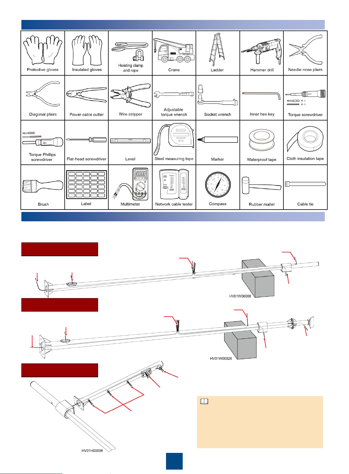
Tools
Routing Cables Through the Pole
3
1. Place the pole on a wooden case or a similar object.
2. Route a pull wire.
3. Route cables.
Routing Cables Through
the Grid Hybrid Pole
Mains AC cable
and optical fiber
Module
ground cable
Mains AC cable, module ground
cable, optical fiber, camera cable,
and PMP microwave cables
Routing Cables Through
the Solar Hybrid Pole
Mains AC
cable and
optical fiber
Module
ground cable
Mains AC cable, module
ground cable, optical fiber,
camera cable, PMP microwave
cables, and PV cable
Routing Cables Through
the Cantilever
Camera
ground cable
PMP microwave cables
Camera signal cable,
power cable, and
alarm cable
PMP microwave cables
PV DC input cable
Camera signal cable,
power cable, and
alarm cable
Dome camera signal cable,
power cable, alarm cable, and
ground cable
Bullet camera signal
cable, power cable,
and ground cable
2
PMP microwave cables can be used only in scenarios
where the PMP microwave is adopted.
The cables routed from the pole cable hole have a
length of 1.5 m reserved. The cables routed from the
cantilever cable hole have a length of 0.5 m reserved.
The object where the pole is placed should be able to
bear a load above 700 kg.
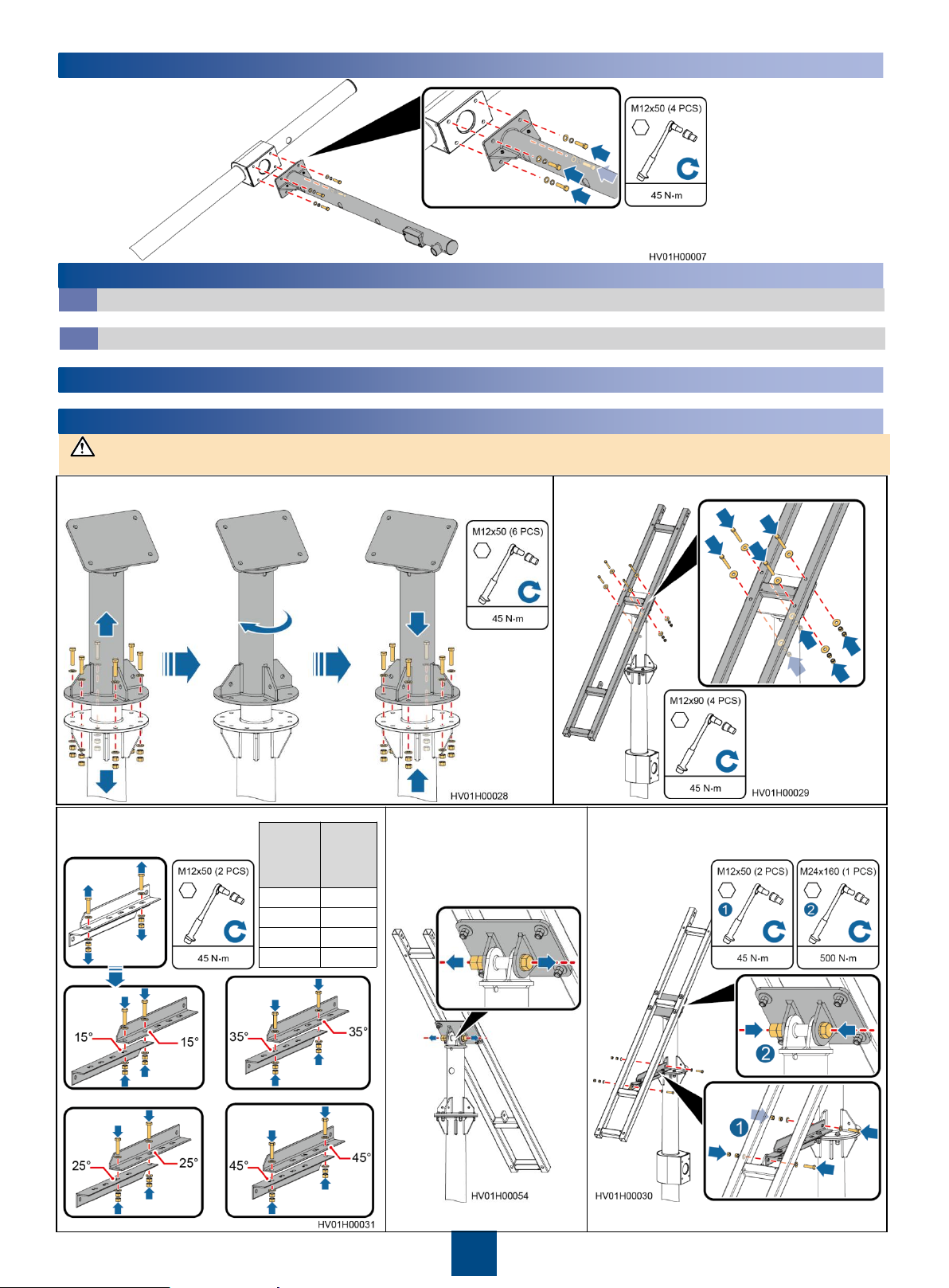
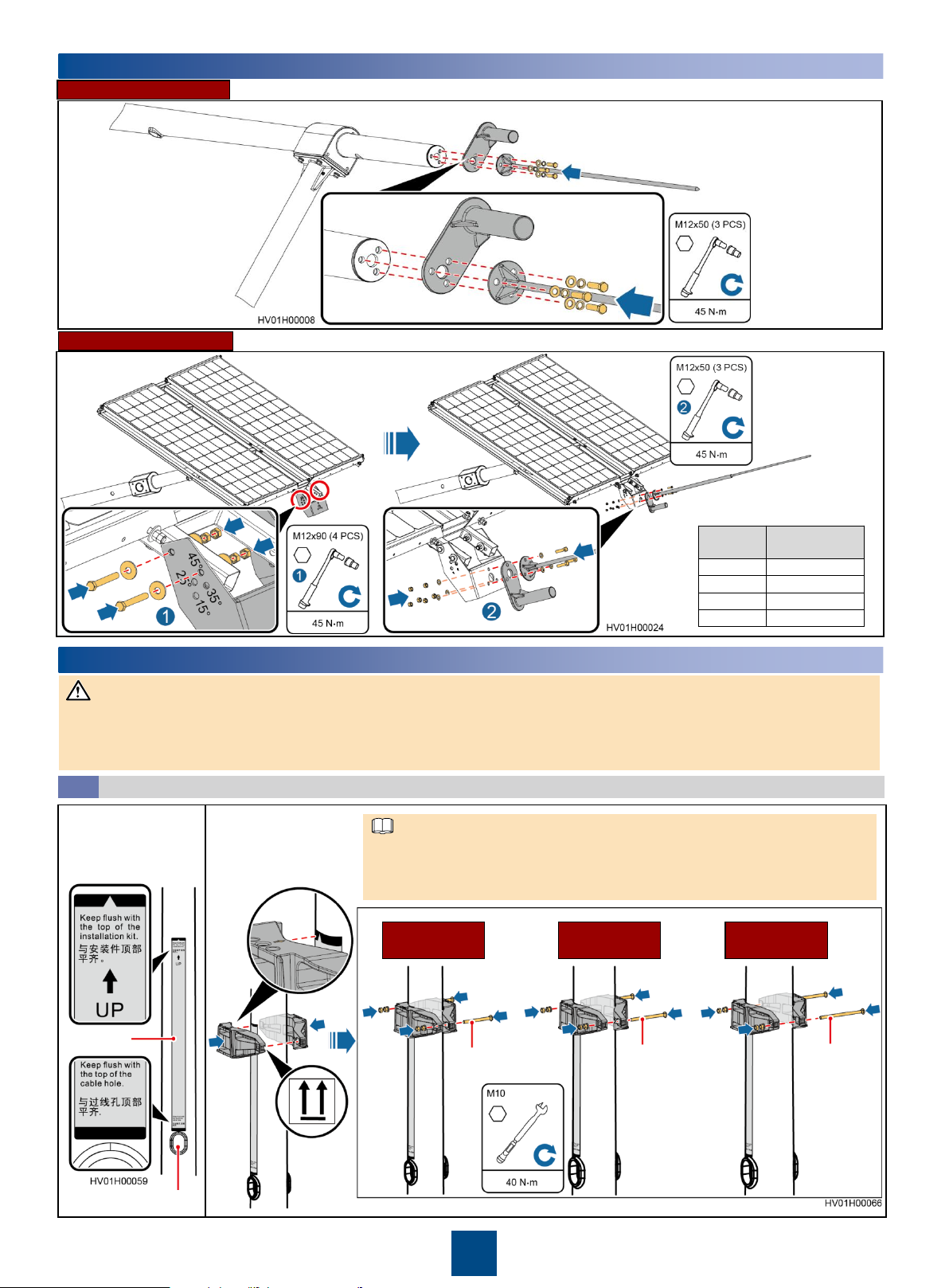
Installing a Cantilever
NOTICE
Site
Latitude
PV
Module
Tilt
Angle
0–15°
15°
16–25°
25°
26–30°
35°
31–45°
45°
4
Installing Cameras and Cables
5
Installing Cameras
5.1
For the camera installation method, see the camera document.
Installing Camera Cables
5.2
For the cable connections at the camera side, see the camera document. Reserve the other ends of cables.
(Optional) Installing the PMP Microwave
6
For the PMP microwave installation method, see the PMP microwave product document.
Installing PV Modules and Cables (Solar Hybrid Scenario)
7
In the northern hemisphere, PV modules face due south. In the southern hemisphere, PV modules face due north.
1. Remove the connective kit, adjust the PV module direction based on the
PV module direction principles, and then reinstall the connective kit.
2. Install the PV module support.
3. Adjust the tilt angle of the PV
module support based on the
site latitude.
or
or
or
4. Loosen the bolt at the
base of the PV module
support.
3
5. Install the angle adjustment bracket and
tighten the bolt at the base of the PV module
support.
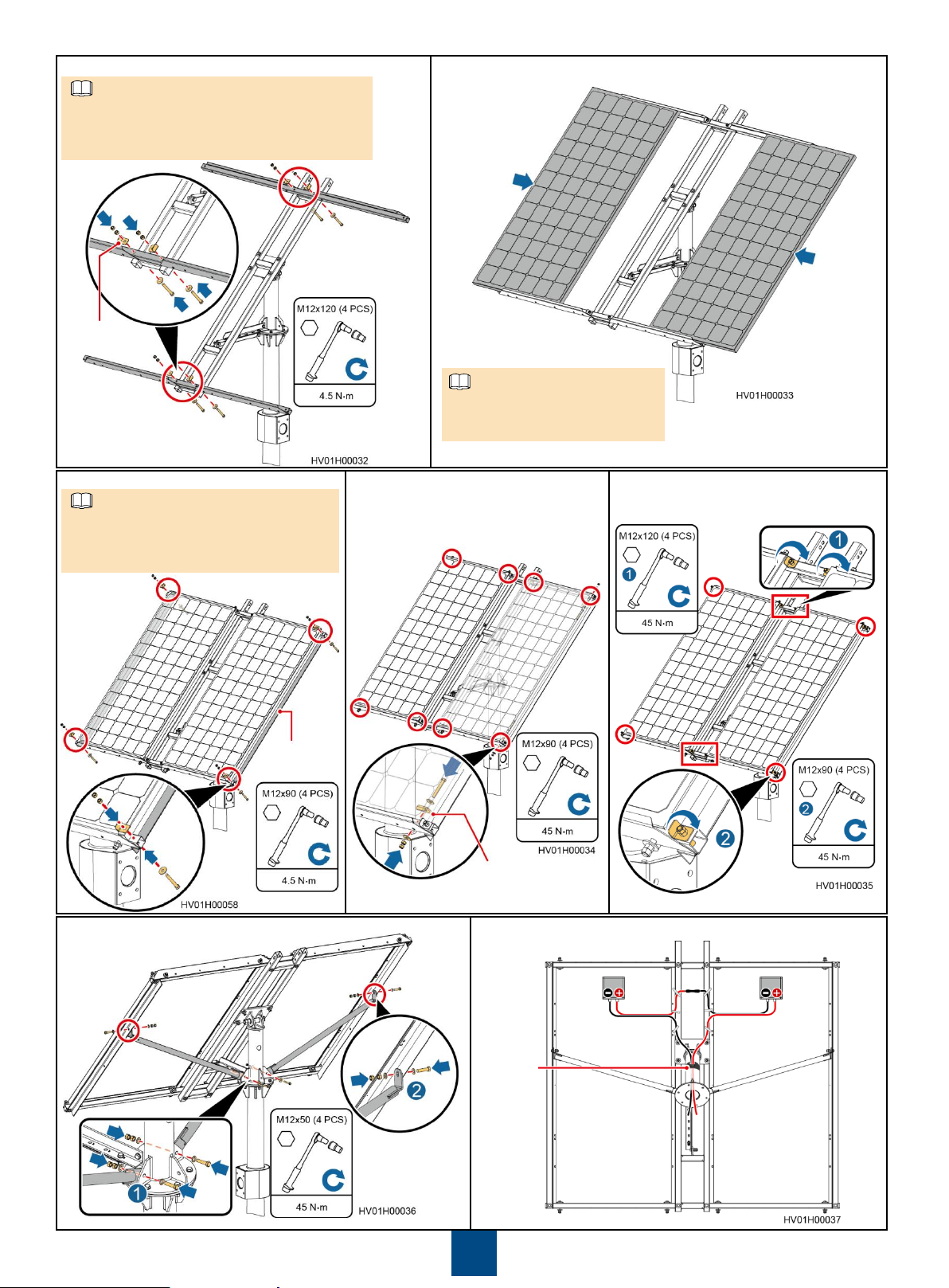
6. Install horizontal beams.
NOTE
NOTE
NOTE
Keep the slots of horizontal beams facing
inwards for installing PV modules.
Partially tighten the bolts so that PV modules
can be adjusted during installation.
Spacing shim
7. Install two PV modules.
Ensure that the junction boxes on the
rear of PV modules are positioned
consistently.
8. Install raking strut beams for the PV modules.
9. Install spacing shims for the
PV modules.
Ensure that the openings of the raking
strut beams face outwards.
Partially tighten the bolts to prevent the
PV modules from sliding.
Raking
strut beam
Spacing shim
11.Install raking struts for the PV modules. 12.Install PV cables.
10.Tighten the bolts at the horizontal
beams and raking strut beams.
Adhesive
tape
4
Installing an Antenna Fastener and Lightning Rod
Site
Latitude
Lightning Rod
Tilt Angle
0–15°
15°
16–25°
25°
26–30°
35°
31–45°
45°
NOTICE
NOTE
8
Grid Hybrid Scenario
Solar Hybrid Scenario
Adjust the tilt angle of the lightning
rod based on the site latitude.
Installing the Function Module and Lithium Battery
9
Wear gloves during installation.
Do not place a module with its bottom against the ground.
Never install a module with power on. Ensure that the angle between a module and the line vertical to the ground is within 10 degrees.
The paint on the module exterior should be intact. If paint has flaked off, repaint the area to avoid corrosion.
Installing the Function Module and Lithium Battery on a Pole
9.1
1. Use a positioning
sticker to mark the
installation position for
the pole mounting kit.
Positioning
sticker
2. Install the pole
mounting kit.
Ensure that the arrow on the top of the pole mounting kit points exactly to the middle
point on the top of the positioning sticker.
There are three types of bolts available for installing the pole mounting kit. Choose
the appropriate type of bolts based on the pole diameter.
Pole Diameter
(105–140 mm)
Bolt (120 mm)
Pole Diameter
(140–175 mm)
Bolt (160 mm)
Pole Diameter
(175–210 mm)
Bolt
(190 mm)
Cable hole
5
 Loading...