

S7-PRO Maintenance Manual (Basic Version V2.1)
INTERNAL
2012-07-20
Huawei Proprietary and Confidential
Copyright © Huawei Technologies Co., Ltd.
Page 1 of 97
Mediapad Maintenance Manual (Basic Version V2.1)
Huawei Technologies Co., Ltd.
All Rights Reserved

S7-PRO Maintenance Manual (Basic Version V2.1)
INTERNAL
2012-07-20
Huawei Proprietary and Confidential
Copyright © Huawei Technologies Co., Ltd.
Page 2 of 97
Contents
1 Product Introduction .................................................................................................................... 4
1.1 Appearance ....................................................................................................................................................... 4
1.2 S7 PRO Models ................................................................................................................................................ 4
1.3 Product Specifications ...................................................................................................................................... 4
2 Maintenance Instructions ............................................................................................................ 6
2.1 Application Scope ............................................................................................................................................ 6
2.2 Maintenance Precautions .................................................................................................................................. 6
2.3 Maintenance Information ................................................................................................................................. 6
3 Exploded View Drawing ............................................................................................................. 7
4 Components on the Main Board ................................................................................................ 8
4.1 Diagram of Components on the Mediapad Main Board ................................................................................... 8
4.2 BOM List ......................................................................................................................................................... 9
5 Software Upgrade ....................................................................................................................... 14
5.1 Preparation ..................................................................................................................................................... 14
5.2 Upgrade Using the Micro SD Card ................................................................................................................ 14
5.2.1 Upgrade Process .................................................................................................................................... 14
5.2.2 Troubleshooting .................................................................................................................................... 15
5.3 Upgrade Using the USB ................................................................................................................................. 16
5.3.1 Entering the USB Upgrade Mode ......................................................................................................... 16
5.3.2 Installing the USB Device Driver ......................................................................................................... 16
5.3.3 Programming Using the QPST Software .............................................................................................. 19
5.3.4 Troubleshooting .................................................................................................................................... 24
5.4 Viewing the Software Version ........................................................................................................................ 26
6 Maintenance Tools ...................................................................................................................... 26
7 Disassembly Procedures ............................................................................................................ 28
8 Assembly Procedures ................................................................................................................. 33
9 Troubleshooting for Common Failures .................................................................................. 37
9.1 Principle ......................................................................................................................................................... 37
9.2 Power-on Failure ............................................................................................................................................ 40
9.2.1 Power-on Failure — High Current ........................................................................................................ 47

S7-PRO Maintenance Manual (Basic Version V2.1)
INTERNAL
2012-07-20
Huawei Proprietary and Confidential
Copyright © Huawei Technologies Co., Ltd.
Page 3 of 97
9.2.2 Power-on Failure — Low Current ........................................................................................................ 50
9.3 Charge Failure ................................................................................................................................................ 51
9.4 Failure to Identify SIM Card ................................................................ ................................ .......................... 52
9.5 Failure to Identify SD Card ............................................................................................................................ 54
9.6 Display Failure ............................................................................................................................................... 58
9.7 Touchscreen Failure ....................................................................................................................................... 60
9.8 Audio Failure .................................................................................................................................................. 61
9.8.1 Speaker Failure ..................................................................................................................................... 61
9.8.2 Headset Failure ..................................................................................................................................... 63
9.9 Camera Failure ............................................................................................................................................... 63
9.10 Vibration Failure .......................................................................................................................................... 64
9.11 RF Failure ..................................................................................................................................................... 65
9.12 Maintenance Procedures for Transmit Failure.............................................................................................. 69
9.12.1 WCMDA2100 Transmit Calibration Failure ....................................................................................... 69
9.12.2 WCMDA1900 Transmit Calibration Failure ....................................................................................... 70
9.12.3 AWS Transmit Calibration Failure ...................................................................................................... 71
9.12.4 WCMDA850 Transmit Calibration Failure ......................................................................................... 72
9.12.5 WCMDA900 Transmit Calibration Failure ......................................................................................... 73
9.12.6 GSM HB Transmit Calibration Failure ............................................................................................... 74
9.12.7 GSM LB Transmit Calibration Failure................................................................................................ 75
9.13 Maintenance Procedures for Receiving Failure............................................................................................ 76
9.13.1 Maintenance Procedures for WCDMA Receiving Failure .................................................................. 76
9.13.2 Maintenance Procedures for GSM Receive Failure ................................................................ ............ 77
9.14 GPS Failure .................................................................................................................................................. 78
9.15 Wi-Fi/BT Failure .......................................................................................................................................... 80
10 Diagram of Soldered Connections on PCB and BGA Chip .............................................. 82
11 Function Test .............................................................................................................................. 82
11.1 MMI Test ...................................................................................................................................................... 82
11.2 Voice Call Test .............................................................................................................................................. 96
S7-PRO Maintenance Manual (Basic Version V2.1)
INTERNAL
2012-07-20
Huawei Proprietary and Confidential
Copyright © Huawei Technologies Co., Ltd.
Page 4 of 97
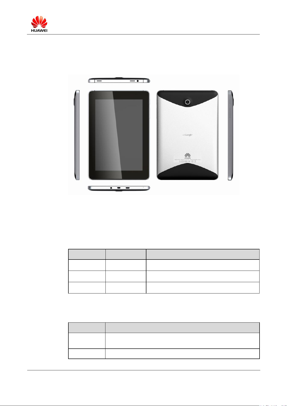
1 Product Introduction
Model
Specification
Standard and Frequency Band
S7-301u
UMTS 900
UMTS 900 MHz/2100 MHz
S7-302u
UMTS 850
UMTS 850 MHz/1900 MHz/2100 MHz
S7-303u
UMTS AWS
UMTS 1900 MHz/2100 MHz/AWS
Item
Description
Dimensions (H
x W x D)
190 mm x 124 mm x 10.5 mm
Weight
About 390 g
1.1 Appearance
1.2 S7 PRO Models
The following table lists the S7-PRO models and related descriptions.
The MediaPad has several models. The following table lists the differences between these
models.
1.3 Product Specifications
S7-PRO Maintenance Manual (Basic Version V2.1)
INTERNAL
2012-07-20
Huawei Proprietary and Confidential
Copyright © Huawei Technologies Co., Ltd.
Page 5 of 97
Item
Description
Power supply
Input: 100–240 V AC, 50 Hz/60 Hz
Output: 5 V DC, 2.0 A
Antenna
Built-in antenna
Technical
standards
3GPP FDD Release 6
WCDMA 900/2100 MHz & HSDPA 14.4 Mbit/s & GSM/GPRS/EDGE
850/900/1800/1900 MHz
S7-PRO-301u
frequency band
850 MHz (CLR): 824 MHz-849 MHz/869 MHz-894 MHz
(uplink/downlink)
900 MHz (GSM): 880 MHz-915 MHz/925 MHz-960 MHz
(uplink/downlink)
1900 MHz (PCS): 1850–1910 MHz/1930–1990 MHz (uplink/downlink)
2100 MHz (IMT): 1920–1980 MHz/2110–2170 MHz (uplink/downlink)
AWS: 1710–1755 MHz/2110–2155 MHz (uplink/downlink)
Battery
Li-ion battery
3.7 V, 4100 mAh
Video playback time: about 6 hours
Standby time: about 369 hours
Interface
3.5 mm TRRS stereo headset interface
MicroSD card slot: compatible with an SDHC card of a maximum
capacity of 32 GB
USB port: Micro USB 2.0
HDMI: HDMI 1.3b type D
SIM card slot
Display screen
Type: IPS LCD, Glare
Size: 7 inches
Resolution: WXGA (1280x800 pixels), 217 ppi
Visual angles: upward 89°/downward 89°/leftward 89°/rightward 89°
Colors: 16,000,000 colors
Contrast: 800:1
Brightness: 400 cd/m2 (maximum)
Touchscreen
7-inch captive touchscreen
Camera
Front camera: 1.3 megapixels, rear camera: 5 megapixels, autofocus
S7-PRO Maintenance Manual (Basic Version V2.1)
INTERNAL
2012-07-20
Huawei Proprietary and Confidential
Copyright © Huawei Technologies Co., Ltd.
Page 6 of 97
Item
Description
GPS
Qualcomm GPS
Bluetooth (BT)
Standard: 2.1 + EDR
Configuration: A2DP, HFP, HSP, and PBAP
Wi-Fi
Standards: IEEE 802.11b/g/n, WEP, WPA, and WPA2
Working frequency band: 2.4 GHz
Working
environment
Working temperature: –10°C to +45°C (14°F to 113°F)
Storage temperature: –40°C to +70°C (–40°F to 158°F)
Humidity: 5% to 95% RH (non-condensing)
Electrostatic discharging is the major cause for the damage of sensitive electronic
components. Each service site should attach great importance to the electrostatic
discharging and strictly observe the antistatic measures described in this manual.
2 Maintenance Instructions
2.1 Application Scope
This document provides instructions for the maintenance of Huawei products by technical
personnel at service sites authorized by Huawei. This manual is Huawei proprietary and is
only permitted to be used by authorized service sites or companies. Although every effort has
been made to ensure the accuracy, mistakes may still be found. If you find any error or have
any suggestions, contact our customer service personnel.
2.2 Maintenance Precautions
Only qualified technicians are allowed to perform maintenance and calibration.
Always wear ESD wrist straps during operation and conduct the maintenance in an ESD
room.
Ensure that all components, screws, and insulators are properly installed after
maintenance and calibration. Ensure that all cables are properly connected.
Ensure that the soldering complies with environmental requirements and is lead-free.
2.3 Maintenance Information
To obtain related product and maintenance information, visit
http://www.huaweidevice.com/cn/technicaIndex.do
S7-PRO Maintenance Manual (Basic Version V2.1)
INTERNAL
2012-07-20
Huawei Proprietary and Confidential
Copyright © Huawei Technologies Co., Ltd.
Page 7 of 97
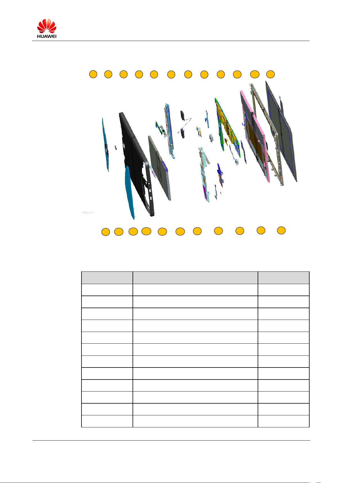
3 Exploded View Drawing
1
13
2 3
4
5
6
14
15
16
7
8
9 10
11 12
17
18
19
20 21
22 23
No.
Description
Quantity
1
Rear camera lens
1
2
Cover B assembly
1
3
POGO PIN
1
4
Diversity antenna support
1
5
Speaker
1
6
Rear camera
1
7
Headset connector
1 8 Speaker FPC
1 9 Main board
1
10
LCD
1
11
Cover A assembly
1
12
TP
1
The exploded view shows the phone structure only and cannot be regarded as a reference for
applying for spare parts.
S7-PRO Maintenance Manual (Basic Version V2.1)
INTERNAL
2012-07-20
Huawei Proprietary and Confidential
Copyright © Huawei Technologies Co., Ltd.
Page 8 of 97
No.
Description
Quantity
13
Left decorative cover
1
14
Right decorative cover
1
15
Side buttons
1
16
Battery
1
17
Wi-Fi antenna support
1
18
MIC-FPC
1
19
MIC
1
20
SUB FPC
1
21
Front camera
1
22
DC-JACK
1
23
SUB-PCB-FPC
1
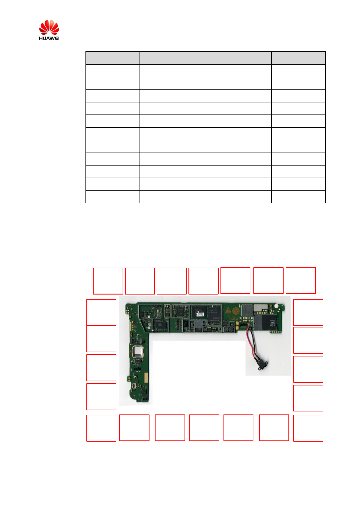
J48 battery socket
Failure symptom:
power-on failure
with no DC
inserted
U7 power supply
control IC
(PM8058)
Failure symptom:
power-on failure
and other failures
U12 NAND Flash-
EMMC-WLAN
Failure symptom:
WLAN failure
U34 CPU
(MSM8260)
Failure symptom:
power-on failure,
RF failure, and
other failures
J10 touchscreen
connector
Failure symptom:
nothing happens
when you touch the
screen
U48 charger IC
Failure symptom:
battery charging
fails
J24 SIM card
socket
Failure symptom:
SIM registration
fails
U36 touchscreen
and speaker driver
IC
Failure symptom:
touchscreen and
speaker failure
U1 LCD
management IC
Failure symptom:
display failure
U2 power
management IC
(PM8901)
Failure symptom:
power-on failure
and other failures
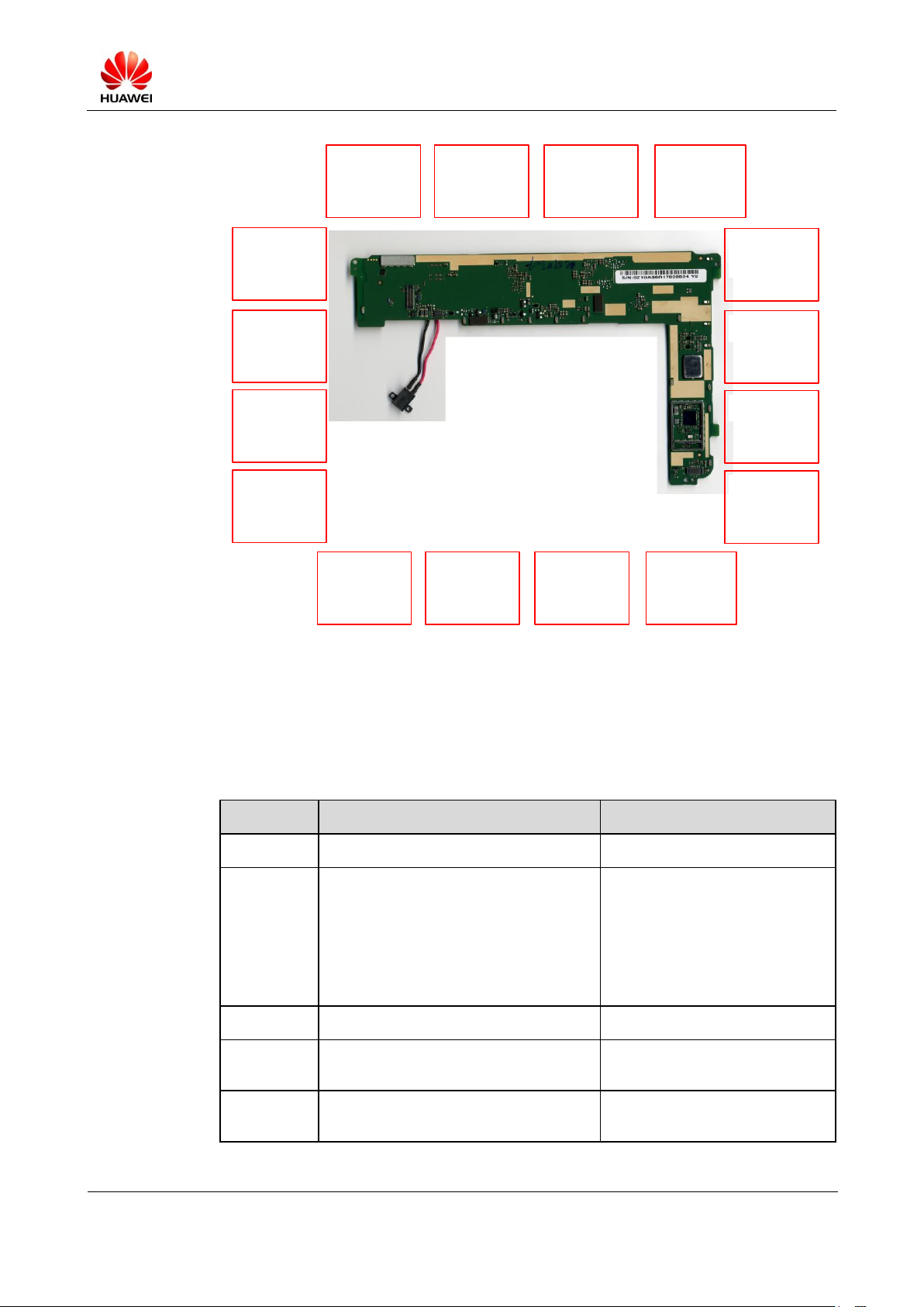
U20/22/24/25 RF
power module
Failure symptom:
abnormal RF
transmitter power
U47 RF power
module
Failure symptom:
RF failure
U23 RF modem
Failure symptom:
RF failure
J21 speaker FPC
connector
Failure symptom:
no voice
U33 RF signaling
regulating sensor
Failure symptom:
RF failure
J2 rear camera
connector
Failure symptom:
rear camera failure
U40 LCD
management IC
Failure symptom:
display failure
J31 Headset
connector
Failure symptom:
no voice
J12 connector for
power-on and voice
buttons
Failure symptom:
failure to power on
and adjust the voice
U6 6D sensor with
accelerometer and
compass
Failure symptom:
accelerometer and
compass failure
LCD-FPC
connector
Failure symptom:
display failure
U17 voltage-level
transformer IC
Failure symptom:
display failure
U7 power supply
control IC
(PM8058)
Failure symptom:
power-on failure
and other failures
U12 NAND FlashEMMC-WLAN
Failure symptom:
WLAN failure
U34 CPU
(MSM8260)
Failure symptom:
power-on failure,
RF failure, and
other failures
J10 touchscreen
connector
Failure symptom:
nothing happens
when you touch the
screen
U48 charger IC
Failure symptom:
battery charging
fails
J24 SIM card
socket
Failure symptom:
SIM registration
fails
U36 touchscreen
and speaker driver
IC
Failure symptom:
touchscreen and
speaker failure
U1 LCD
management IC
Failure symptom:
display failure
U2 power
management IC
(PM8901)
Failure symptom:
power-on failure
and other failures
U20/22/24/25 RF
power module
Failure symptom:
abnormal RF
transmitter power
U47 RF power
module
Failure symptom:
RF failure
U23 RF modem
Failure symptom:
RF failure
J21 speaker FPC
connector
Failure symptom:
no sound
U33 RF signal
regulating sensor
Failure symptom:
RF failure
J2 rear camera
connector
Failure symptom:
rear camera failure
U40 LCD
management IC
Failure symptom:
display failure
J31 Headset
connector
Failure symptom:
no sound
J12 connector for
power-on and
sound
Failure symptom:
failure to power on
and adjust the
sound
U6 6D sensor with
accelerometer and
compass
Failure symptom:
accelerometer and
compass failure
LCD-FPC
connector
Failure symptom:
display failure
U17 level shifter IC
Failure symptom:
display failure
4 Components on the Main Board
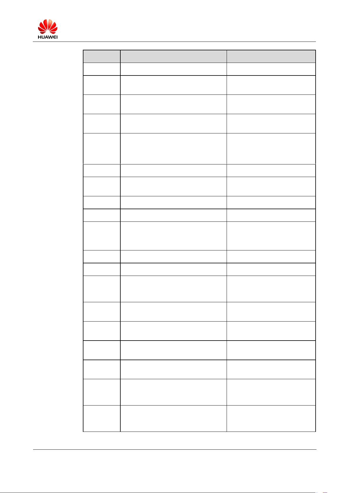
4.1 Diagram of Components on the Mediapad Main Board
S7-PRO Maintenance Manual (Basic Version V2.1)
INTERNAL
2012-07-20
Huawei Proprietary and Confidential
Copyright © Huawei Technologies Co., Ltd.
Page 9 of 97
U4 voltage-level translator
for RF power amplifier
control signal
Failure symptom: RF
failure
U13 RF switch
Failure symptom: RF
failure
U3 RF low noise amplifier
Failure symptom: RF
failure
U19 voltage-level
transformer IC for
touchscreen signal
Failure symptom:
touchscreen failure
J8 auxiliary board FPC
connector for USB/HDMI/
SD card
Failure symptom: USB/
HDMI/SD card failure
U10 voltage-level
transformer IC
Failure symptom:
coulometer failure
U1001 current limiting IC
Failure symptom: USBHOST faults
U37 coulometer
Failure symptom:
coulometer failure
U16 voltage-level
transformer IC for
touchscreen signal
Failure symptom:
touchscreen failure
U15 speaker power
amplifier
Failure symptom: no sound
U14 speaker power
amplifier
Failure symptom: no sound
U11 BT/Wi-Fi driver IC
Failure symptom: BT/Wi-Fi
failure
. U18 coulometer I2C
voltage-level transformer IC
Failure symptom:
coulometer failure
U9 voltage-level
transformer IC for
touchscreen I2C signal
Failure symptom:
touchscreen failure
U35 touchscreen power
management IC
Failure symptom:
touchscreen failure
J6 front camera connector
Failure symptom: front
camera failure
BOM
Description
Location
15010248
Schottky diode-30 V-0.2 A-0.5 V
D1
15040238
Transient voltage suppression diode-6
V-14 V-10 W-12 A
D10, D1002, D1003, D1004,
D1005, D1006, D1007, D1100,
D13, D17,
D18, D19, D2, D23, D24, D25,
D26,
D27, D3, D5, D6, D9
15010235
Schottky diode-40 V-0.5 A-0.425 V
D12
14240309
IO connector-female-5pin-WTB
connector-SMT
J1
14240181
BTB connector-female-24-0.4 mm-1
mm-SMT
J2, J6
4.2 BOM List
The following table is provided for reference only and is subject to change without notice.
The latest component list is available on corresponding Huawei system. If you have any
questions, contact the local technical personnel
S7-PRO Maintenance Manual (Basic Version V2.1)
INTERNAL
2012-07-20
Huawei Proprietary and Confidential
Copyright © Huawei Technologies Co., Ltd.
Page 10 of 97
BOM
Description
Location
14240004
RF connector-straight-female-SMT
J19, J3, J4
51621274
Main antenna SMT spring
J13, J14, J15, J20, J23, J27, J30,
J32, J5
14240210
BTB connector-female-40Pin-0.4
mm-0.9 mm
J8, J9
14240199
BTB connector-female-10pin-0.4
mm-0.9 mm
J10, J12, J21
51621023
Ground spring
J11, J25, J26, J28, J29, J33,
J34, J35, J36, J37, J38, J39, J40,
J41, J42, J43, J44, J45, J46, J48
14240301
Card connector-SIM card socket
J24
14240283
FPC connector-11-0.3 mm-0.1 mm-0.6
mm
J31
15060228
MOSFET-P-channel
Q1, Q17, Q2, Q9
15050014
NPN transistor
Q22, Q5
15060153
MOSFET-N-channel
Q1000, Q1001, Q1101, Q1102,
Q1103,
Q1104, Q1105, Q1206, Q19
39110582
Power Driver-Boost DCDC
U1
39200270
Power management IC-PM8901
U2
47090034
RF low noise
amplifier-869-894/1930-1990/2110-217
0 MHz
U3
36020366
CMOS-4BIT bidirectional voltage-level
translator with auto direction sensing
U17, U19, U4
38140016
Semiconductor sensor-6-axis sensor
with accelerometer and compass
U6
39200177
Dedicated power management chip of
Qualcomm MSM7x30 series (PM8058)
U7
40020131
DDR2 DRAM-8Gb LPDDR2-800
MHz-32 bit
U8
36020395
CMOS-4BIT bidirectional voltage-level
translator with auto direction
sensing-I2C bus
U10, U16, U18, U9
39200222
Chip with the combination of single
band 2.4GHz WLAN, Bluetooth 2.1, and
FM-BCM4329
U11

S7-PRO Maintenance Manual (Basic Version V2.1)
INTERNAL
2012-07-20
Huawei Proprietary and Confidential
Copyright © Huawei Technologies Co., Ltd.
Page 11 of 97
BOM
Description
Location
47140045
RF switch-0.5–2.5 GHz
U13
39080077
Audio power amplifier
U14, U15
13080038
Duplexer-RX: 2110–2170 MHz/TX:
1920–1980 MHz
U20
13080060
Duplexer-TX: 824–849 MHz/RX:
869–894 MHz
U21
47100280
Power module-1920–1980 MHz
U22
39200249
WCMDA/GSM radio transceiver
(QTR8615)
U23
47100289
Power module-1850-1910 MHz
U24
47100360
RF power module-1710-1785 MHz
U25
13080072
Duplexer-RX: 2110–2155 MHz/TX:
1710–1755 MHz
U31
38140022
Semiconductor-capacitive sensor
U33
39200289
Digital base band processor-1.2
GHz-MSM8260
U34
39110548
LDO-3.3 V
U35
39110567
Switching regulators-2.0–5.5 V
U36
39070073
Power management IC-0.3–2.75
V-battery coulometer
U37
43140104
Connector controller-LCD Drive IC
U40
13080082
Duplexer-RX: 1930–1990 MHz/TX:
1850–1910 MHz
U41
47090042
RF low noise amplifier-0.5–3 GHz
U42
47140049
RF switch-0.5–3.0 GHz
U43
47140054
RF switch-600–2700 M
U46
47100307
RF power module-824–849 MHz,
880–915 MHz, 1710–1785 MHz,
1850–1910 MHz
U47
39070085
Battery management IC-4.1–16
V-DC-DC charging chip
U48
39070055
Battery management IC-2.5–6.5
V-average current limiting-percentage
(10%)-DRV
U1001
12020141
Crystal oscillator-19.2 MHz
X1
S7-PRO Maintenance Manual (Basic Version V2.1)
INTERNAL
2012-07-20
Huawei Proprietary and Confidential
Copyright © Huawei Technologies Co., Ltd.
Page 12 of 97
BOM
Description
Location
12020171
Crystal oscillator-27 MHz
X2
12020125
Crystal oscillator-0.032768 MHz
X3
12020168
Crystal oscillator-37.4 MHz
X4
13010262
SAW filter-2140 MHz
Z1
13010177
SAW filter-1960 MHz
Z3
13010175
SAW filter-1732.5 MHz
Z4
13010265
SAW filter-1574.42 MHz/1605.89 MHz
Z5
07040064
Varistor-8 V-4 V-30
V-SMT-0405-ESD+EMI noise filter
Z10, Z9
13030052
Ceramics filter-2450 MHz
Z11
07040072
ESD_EMI Filter-14 V-30 pF-800–3000
MHz
Z12
13010131
Sound filter-1960 MHz
Z16
13010148
Sound filter-2140 MHz
Z17
13080106
Duplexer-1565–1607 MHz/2400–2500
MHz
Z18
13010264
SAW filter-1590.16 MHz
Z22
40060318
NAND flash-16 GB eMMC V4.4-52
MHz
U12
03021CNP
Interface
board-MediaPad-HIDS7PIA-with TF
slot, type D HDMI, and micro USB
connector
15040238
Transient voltage suppression diode-6
V-14 V-10 W-12 A
D21, D5, D9
15040264
Transient voltage suppression diode-5.5
V-15 V-1 A
D10, D7
15040293
Transient voltage suppression diode-6
V-15 V-15 W-1.5 A
D19, D20
14240243
Card connector-micro SD receptacle
J2
14240272
IO
connector-micro_B-female-5pin-bend-S
MT
J3
14240268
IO connector-micro HDMI-19-D type
J4
14240199
BTB connector-female-10pin-0.4
mm-0.9 mm
J6
S7-PRO Maintenance Manual (Basic Version V2.1)
INTERNAL
2012-07-20
Huawei Proprietary and Confidential
Copyright © Huawei Technologies Co., Ltd.
Page 13 of 97
BOM
Description
Location
14240210
BTB connector-female-40Pin-0.4
mm-0.9 mm
J8
10040059
Common mode EMI filter-20 V DC/280
mA-0805
T1
07040064
Varistor-8 V-4 V-30
V-SMT-0405-ESD+EMI noise filter
Z1
03021CNQ
Speaker
board-MediaPad-HIDS7PSK-1x1
14240200
BTB connector-male-10Pin-0.4 mm-0.9
mm
J1
03021CNW
LED board-MediaPad-HIDS7PFR-1x1
14240200
BTB connector-male-10Pin-0.4 mm-0.9
mm
J3
03021CPB
Key board-S7-301u-HIDS7PKA-1x1
14240200
BTB connector-male-10Pin-0.4 mm-0.9
mm
J1
38140014
Semiconductor sensor-ambient light
sensor
U1
03021CPF
BTB board-MediaPad-HIDS7PFI
14240221
BTB connector-male-40Pin-0.4 mm-0.9
mm
J1, J5
03021DTK
BTB to ZIF FPC bridge
board-MediaPad-HIDS7PFL
14240221
BTB connector-male-40Pin-0.4 mm-0.9
mm
J1
32050018
Vibrator-column
22020058
Speaker
22050048
Microphone
23040205
LCD module-single display
23060061
Camera module group-CMOS-1.3 M-FF
23060062
Camera module group-CMOS-5 M-AF
14240276
IO connector-DC JACK
14240340
Headset connector
27160803
Main antenna-S7-303u-(sensor FPC)
SAA
S7-PRO Maintenance Manual (Basic Version V2.1)
INTERNAL
2012-07-20
Huawei Proprietary and Confidential
Copyright © Huawei Technologies Co., Ltd.
Page 14 of 97
BOM
Description
Location
23070113
Touchscreen-S7 PRO CTP with AF
27160802
Main antenna
S7-303 u-1710–2170 MHz/824–894
MHz
27160804
GPS WIFI antenna
S7-30 3u-1565–1620 MHz/2400–2500
MHz
27160805
Diversity antenna-S7-303 u-1910–2170
MHz
Item
Contents
Remarks
Preparation
Battery
At least two bars on the battery level
indicator
Micro SD card
More than 512 M
USB cable
BOM: 97065432
PC
Windows 2000, Windows XP
File
S7-30Xu V100R001C002B027T01
(not the final version)
This version is only for reference.
Download the latest version for
upgrade (the upgrade using USB).
Tool
eMMC Software Download
For upgrade using the USB
Upgrade
method
Using the Micro SD card
Using the USB
5 Software Upgrade
5.1 Preparation
5.2 Upgrade Using the Micro SD Card
5.2.1 Upgrade Process
Step 1 Delete the information in the Micro SD card or format the SD card.
Step 2 Create a folder named dload in the root directory of the Micro SD card, and copy the upgrade
file to dload.
S7-PRO Maintenance Manual (Basic Version V2.1)
INTERNAL
2012-07-20
Huawei Proprietary and Confidential
Copyright © Huawei Technologies Co., Ltd.
Page 15 of 97
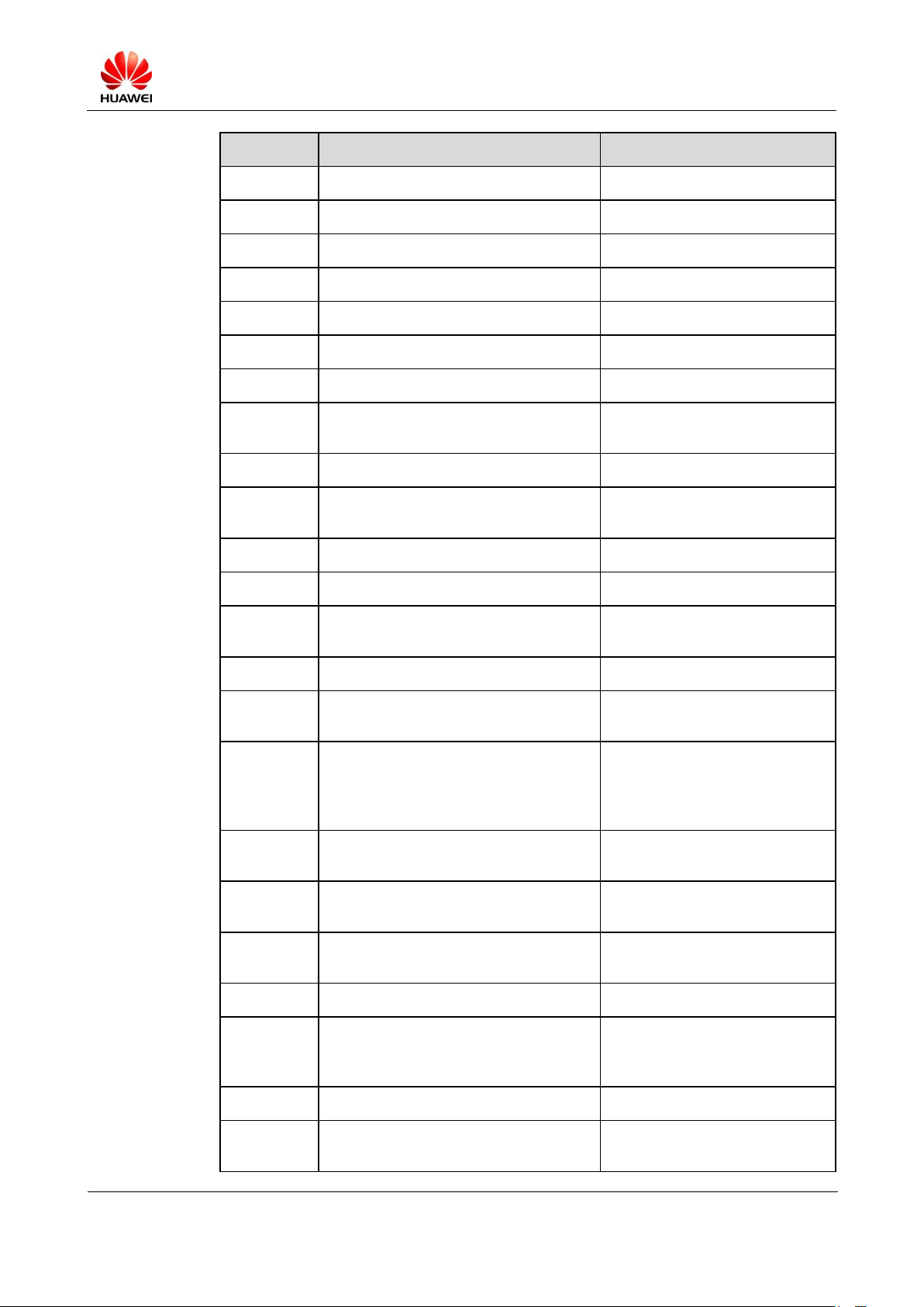
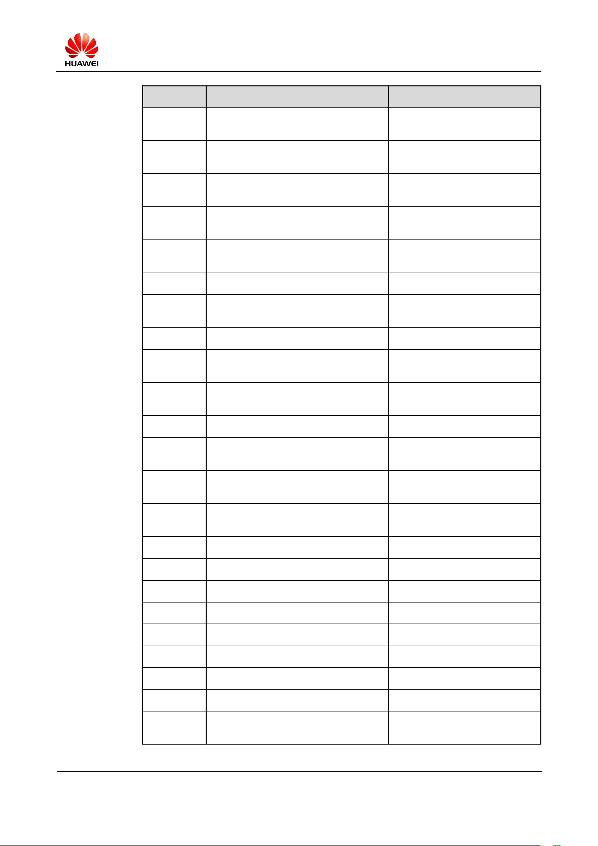
Step 3 Ensure that the board is powered off, and that the battery is fully charged or connected to a
Upgrade
State
Upgrade of the Device
Upgrade of the Board
Upgrading.
The LED indicator blinks at the
frequency of 1 Hz.
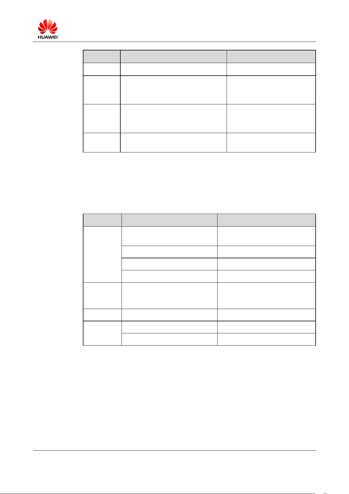
Upgrade
succeeded.
The LED indicator stays on.
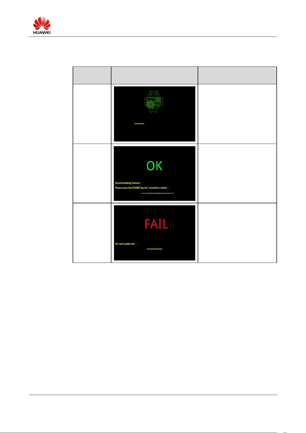
Upgrade
failed.
The LED indicator blinks at the
frequency of 4 Hz.
charger. Insert the Micro SD card into the board, and the upgrade will be performed
automatically after the board is powered on.
Step 4 When the upgrade is completed, remove the SD card and press and hold the POWER button
to restart the device.
5.2.2 Troubleshooting
During the update using the SD card, if the device presents a flash screen indicating the
upgrade failure, check for any mis-operation or incorrect upgrade version. You can remove
the SD card and try it again or change the SD card.
Method to check whether the SD card is damaged:
Because the size of the upgrade package of some version is large, try to open the compressed
upgrade package that is copied to the SD card to check for damage. Remove and plug the SD
card before you open the compressed upgrade package. If you open the compressed upgrade
package directly, the opened package may be a cache on the PC. Alternatively, you can check
the reliable storage capacity of the SD card with the MyDiskTest (an SD card check tool) to
ensure that the size of the upgrade package does not exceed the storage capacity of the SD
card. For more information, see the appendix of this chapter.
S7-PRO Maintenance Manual (Basic Version V2.1)
INTERNAL
2012-07-20
Huawei Proprietary and Confidential
Copyright © Huawei Technologies Co., Ltd.
Page 16 of 97
5.3 Upgrade Using the USB
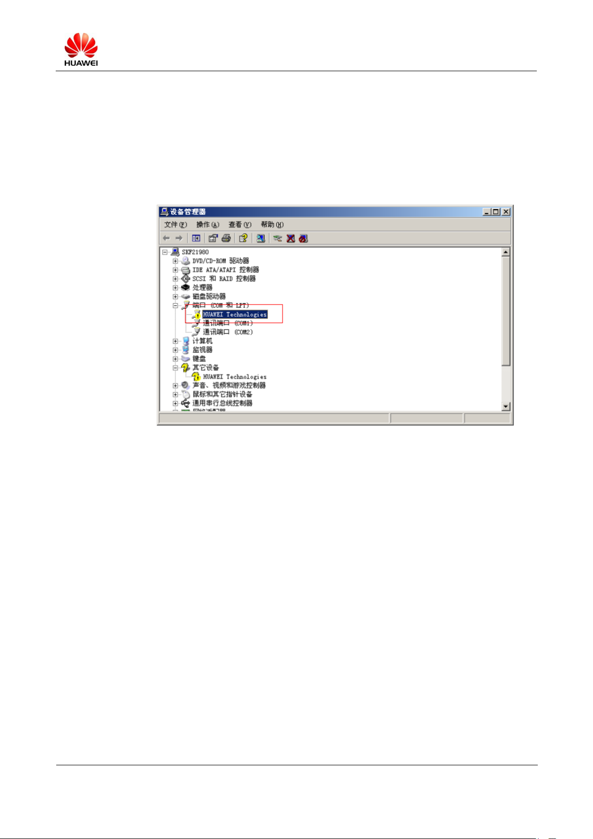
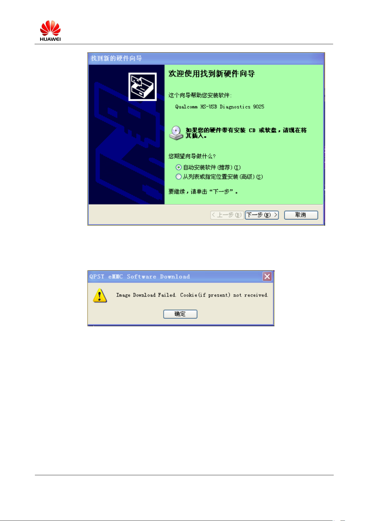
5.3.1 Entering the USB Upgrade Mode
When the system is powered on, quickly press the VOLUME_UP button and the
VOLUME_DOWN button. If it is the first time for your PC to connect the USB, the message
"Found New Hardware" will be displayed, which indicates that the system has entered the
USB upgrade mode successfully, as shown in the following figure.
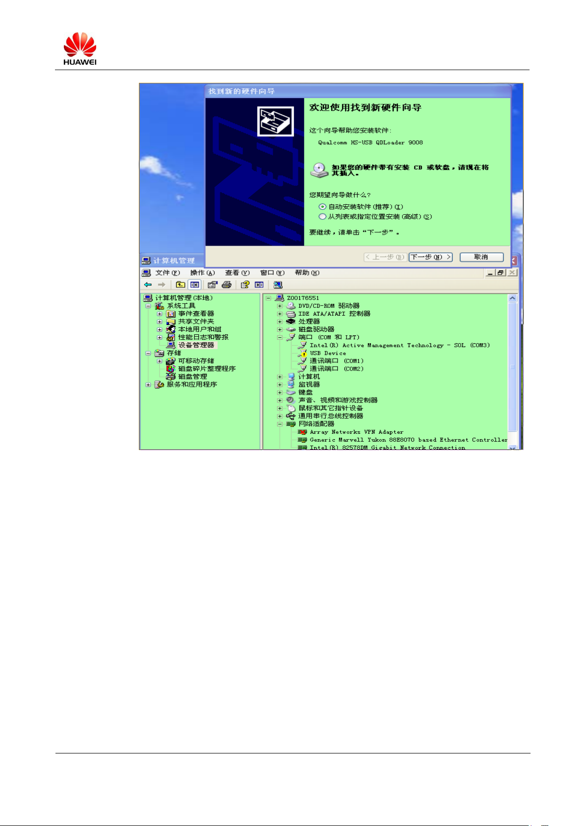
5.3.2 Installing the USB Device Driver
If the driver has not been installed before, you must install the driver on the PC before the
update using the USB.
Step 1 When the MediaPad is connected, it enters into the Emergency Download mode, and a
window is displayed, showing the port Qualcomm HS-USB QDLoader 9008. If the port
driver has not been installed before, a message for installing the driver will be displayed.
S7-PRO Maintenance Manual (Basic Version V2.1)
INTERNAL
2012-07-20
Huawei Proprietary and Confidential
Copyright © Huawei Technologies Co., Ltd.
Page 17 of 97
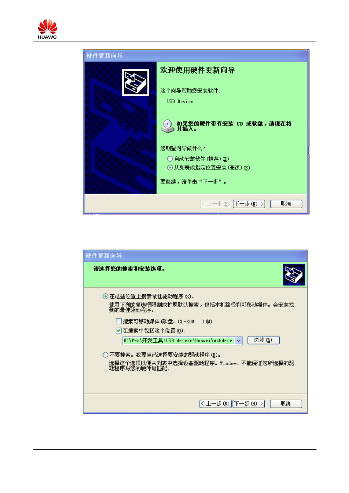
Step 2 Select Choose the install from a list or specific location (Advanced). Then click Next.
S7-PRO Maintenance Manual (Basic Version V2.1)
INTERNAL
2012-07-20
Huawei Proprietary and Confidential
Copyright © Huawei Technologies Co., Ltd.
Page 18 of 97
Step 3 Click Browse in the window displayed to select the USB driver to be installed, as shown in
the following figure. Then click Next.
S7-PRO Maintenance Manual (Basic Version V2.1)
INTERNAL
2012-07-20
Huawei Proprietary and Confidential
Copyright © Huawei Technologies Co., Ltd.
Page 19 of 97
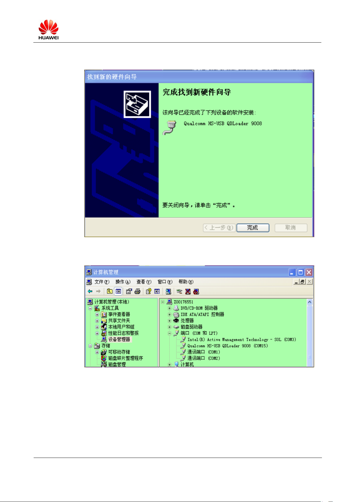
Step 4 If the corresponding file is found, the window indicating successful installation will be
displayed, as shown in the following figure.
Step 5 The USB port (COM15) is shown in the Device Manager window.
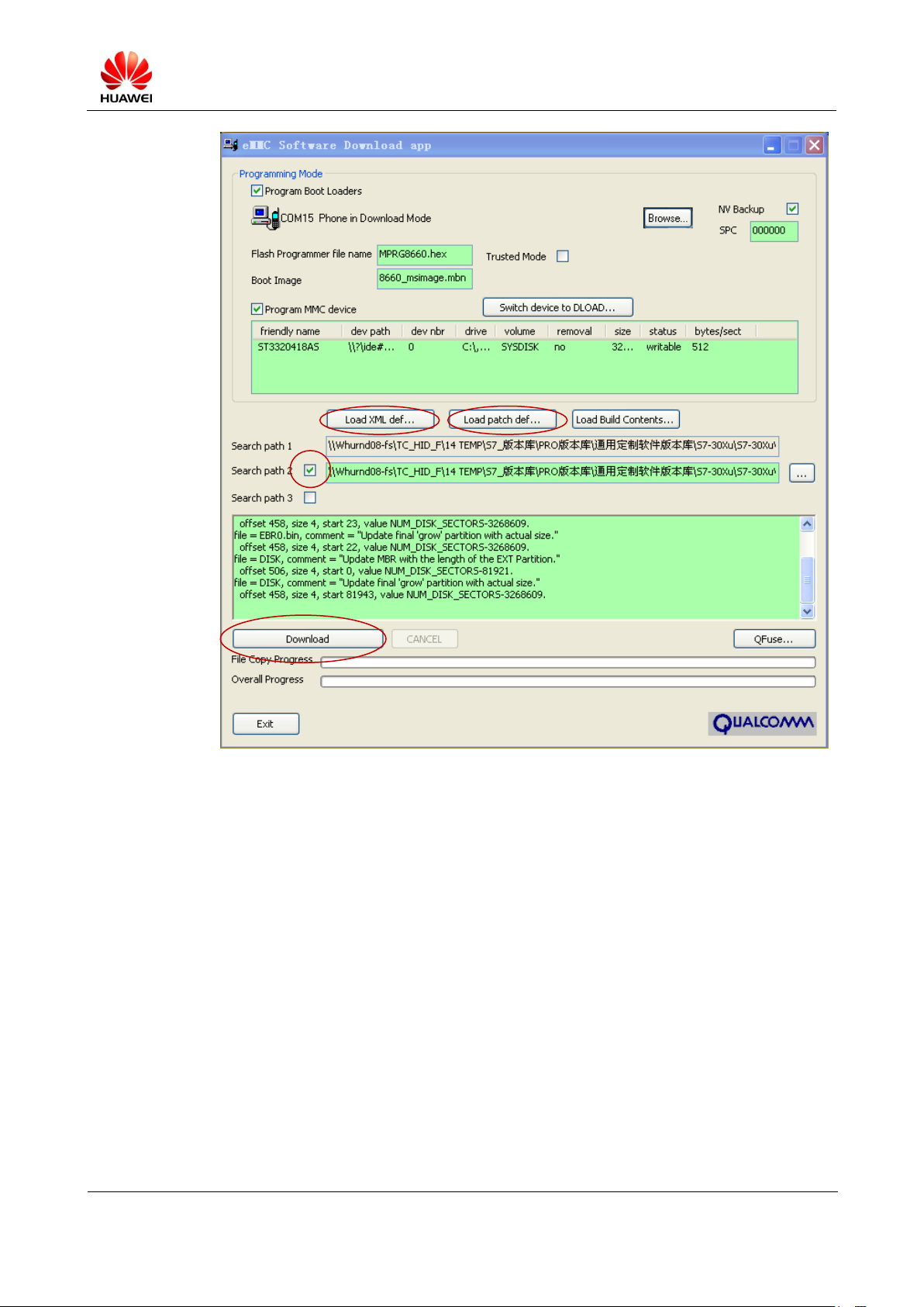
5.3.3 Programming Using the QPST Software
If the QPST software has been installed, run the eMMC Software Download tool and do as
follows:
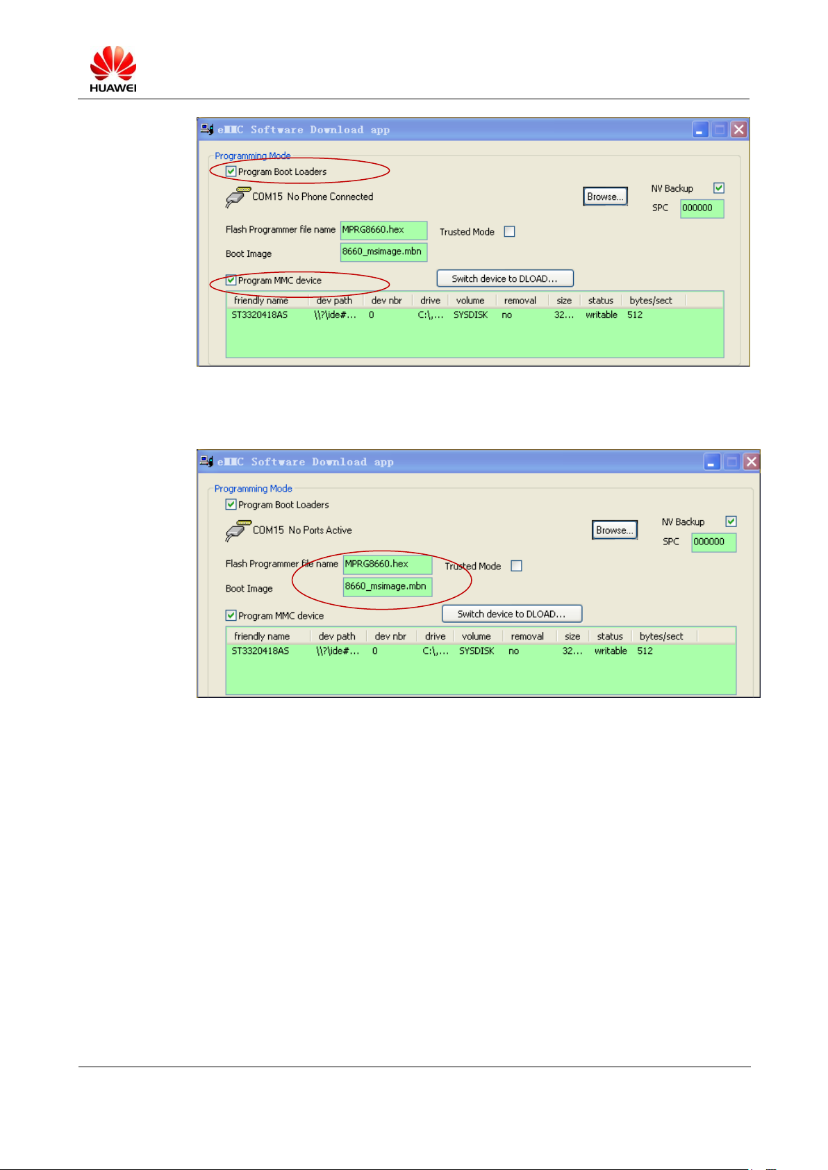
Step 1 Ensure that you select Program Boot Loaders and Program MMC device.
S7-PRO Maintenance Manual (Basic Version V2.1)
INTERNAL
2012-07-20
Huawei Proprietary and Confidential
Copyright © Huawei Technologies Co., Ltd.
Page 20 of 97
Step1
Step 2
Step 2 Set Flash Programmer file name to MPRG8660.hex, and set Boot Image to
8660_msimage.mbn.
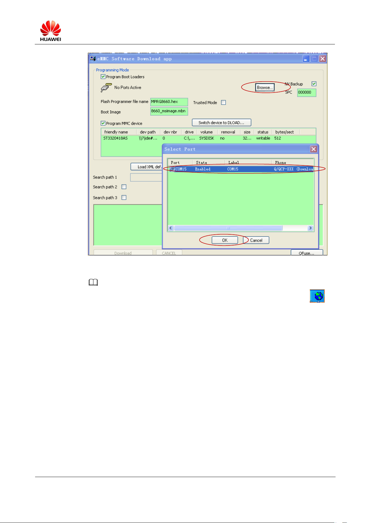
Step 3 Click Browse. In the Select Port window, check whether the value of Phone is Q/QCP-XXX
(Download) (COM15), and whether the port is consistent with that shown in the Device
Manager window. Then click OK.
S7-PRO Maintenance Manual (Basic Version V2.1)
INTERNAL
2012-07-20
Huawei Proprietary and Confidential
Copyright © Huawei Technologies Co., Ltd.
Page 21 of 97
NOTE
Step3
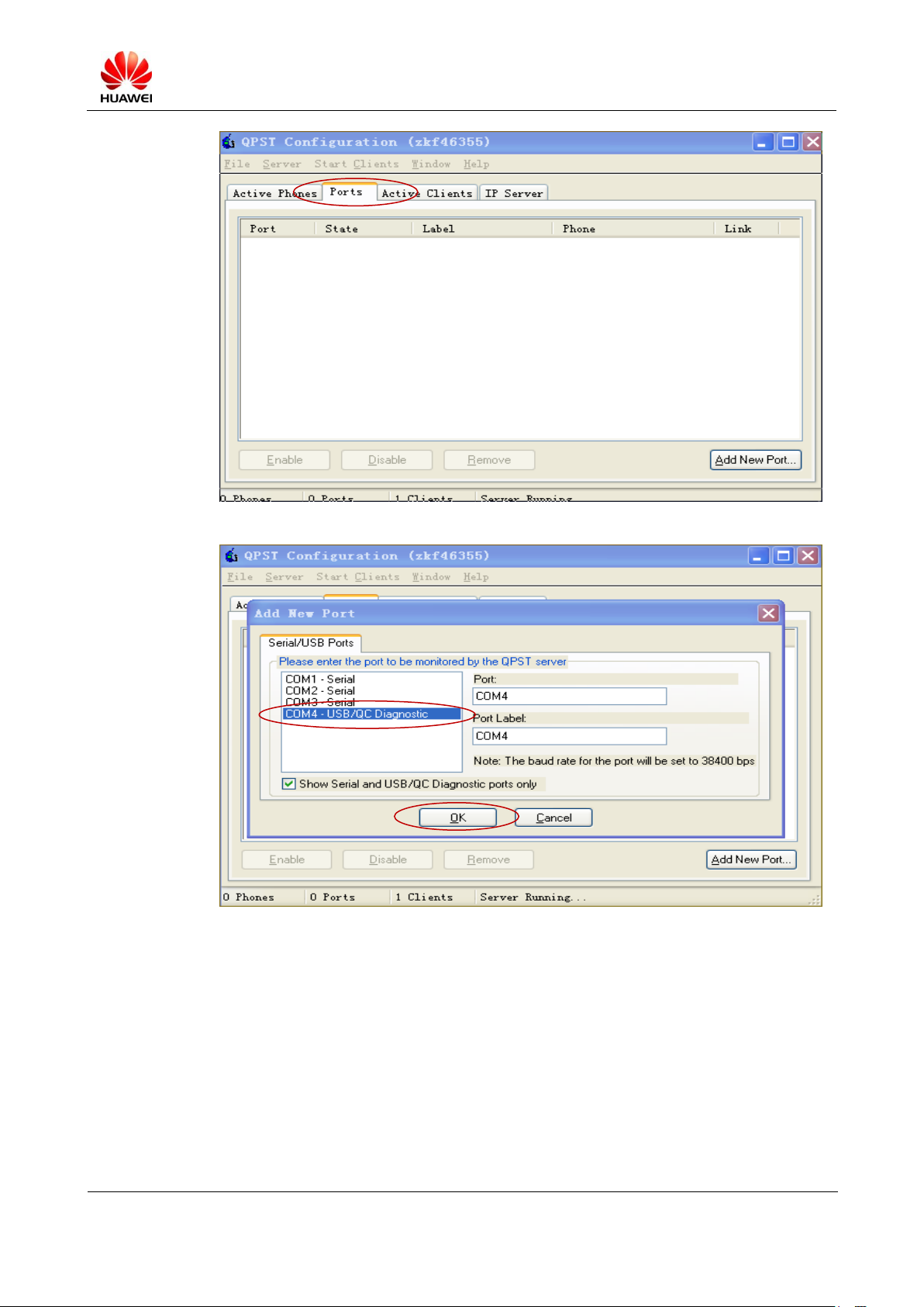
If the Q/QCP-XXX (Download) port is not found in the Select Port window, right-click the
icon in the taskbar on the lower right corner to display the QPST Configuration window. In the
displayed window, click Ports, and click Add New Port. In the Add New Port window displayed,
select corresponding USB/QC Diagnostic port. Double-click the selected port to add it to Port on the
right. Then click OK.
S7-PRO Maintenance Manual (Basic Version V2.1)
INTERNAL
2012-07-20
Huawei Proprietary and Confidential
Copyright © Huawei Technologies Co., Ltd.
Page 22 of 97
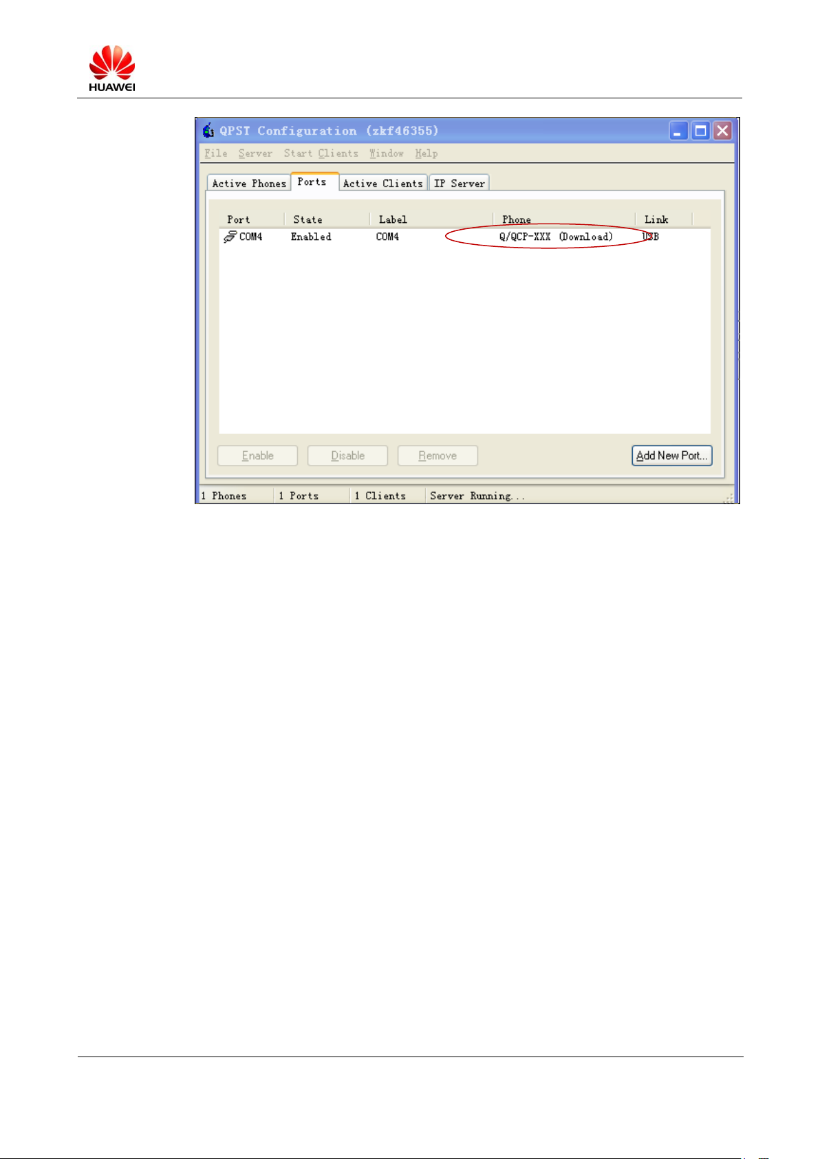
The following window is displayed (if the port is available, the Q/QCP-XXX (Download) is
displayed).
S7-PRO Maintenance Manual (Basic Version V2.1)
INTERNAL
2012-07-20
Huawei Proprietary and Confidential
Copyright © Huawei Technologies Co., Ltd.
Page 23 of 97
Step 4 Click Load XML def, and open the modem folder in the upgrade package in the displayed
box. Then select rawprogram0.xml in the modem folder. If the file is successfully opened,
the save path of rawprogram0.xml will be displayed in Seach path1.
Step 5 Click Load patch def, and open the modem folder in the upgrade package in the displayed
box. Then select patch0.xml in the modem folder (this step is mandatory; otherwise, the
MediaPad startup will fail).
Step 6 Select Search path2, and click the icon for browsing. Then select the apps folder in the
upgrade package in the Seach Path Folder window.
Step 7 When all preceding steps are completed, the Download button will become clickable. Then
click Download.
S7-PRO Maintenance Manual (Basic Version V2.1)
INTERNAL
2012-07-20
Huawei Proprietary and Confidential
Copyright © Huawei Technologies Co., Ltd.
Page 24 of 97
Step 4
Step 5
Step 6
Step 7
Step 8 After the upgrade is completed, press and hold the Power button for more than 10 seconds to
re-start the MediaPad.
5.3.4 Troubleshooting
Click Download, if the following dialog box for installing the driver is displayed, as shown in
the following figure. You can ignore it, because you may enter the trusted mode that requires
no driver (USB MassStorage port is used in the trusted mode).
S7-PRO Maintenance Manual (Basic Version V2.1)
INTERNAL
2012-07-20
Huawei Proprietary and Confidential
Copyright © Huawei Technologies Co., Ltd.
Page 25 of 97
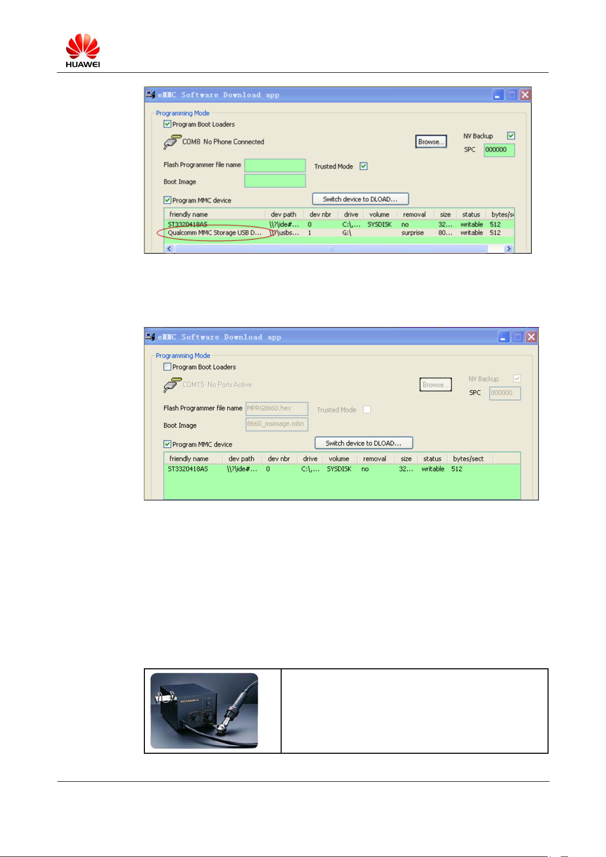
Step 1 In this mode, the message "Remote devices wait for time out" will be displayed occasionally,
or the message "Image Download Failed. Cookie (if present) not received" will be displayed
during restart.
In these cases, you may repeat the preceding steps. If the download fails, restart the MediaPad
and connect it to the PC to check whether the upgrade is conducted in the trusted mode using
the QPST software (that is, the Qualcomm MMC Storage USB Device is displayed). Then
perform the upgrade using the USB according to the steps for upgrade in the trusted mode.
S7-PRO Maintenance Manual (Basic Version V2.1)
INTERNAL
2012-07-20
Huawei Proprietary and Confidential
Copyright © Huawei Technologies Co., Ltd.
Page 26 of 97
Name: constant-temperature hot air gun
Purpose: heat components
Step 2 If the message "Phone is not in download mode" is displayed, you may not uncheck Program
Boot Loaders (mandatory for upgrade in the trusted mode). Then uncheck Program Boot
Loaders as shown in the following figure.
Click Scan&&Download, if the message "port open" is displayed, check whether the driver
is properly installed, and whether DBAdapter Reserved Interface port functions well.
5.4 Viewing the Software Version
In the standby state, choose Settings > About phone to view the information about the
software version.
6 Maintenance Tools

S7-PRO Maintenance Manual (Basic Version V2.1)
INTERNAL
2012-07-20
Huawei Proprietary and Confidential
Copyright © Huawei Technologies Co., Ltd.
Page 27 of 97
Name: constant-temperature hot air gun
Purpose: heat components
Name: soldering iron
Purpose: soldering during maintenance
Name: DC power
Purpose: supply power
Name: soldering
Purpose: secure the main board.
Name: lead-free solder wire
Purpose: soldering
Name: digital multimeter
Purpose: measurement during maintenance
Name: tool kit
Purpose: assemble and disassemble the device
S7-PRO Maintenance Manual (Basic Version V2.1)
INTERNAL
2012-07-20
Huawei Proprietary and Confidential
Copyright © Huawei Technologies Co., Ltd.
Page 28 of 97
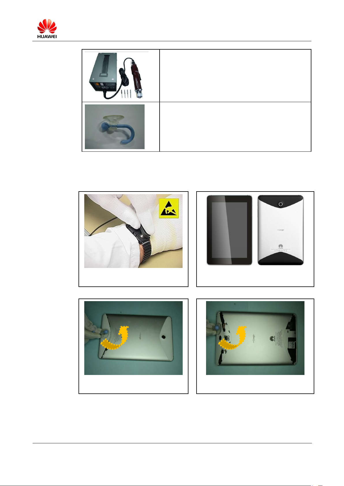
Name: electric screwdriver
Purpose: fasten and remove screws.
Name: small sucker (diameter: about 25 mm)
Purpose: remove the upper decorative cover.
1.
Ensure that the ESD wrist strap is
properly grounded.
2.
Disassembly procedures are as shown
below.
3.
Remove the lower decorative cover
with the sucker.
4.
Remove the upper decorative cover with
the sucker.
7 Disassembly Procedures
S7-PRO Maintenance Manual (Basic Version V2.1)
INTERNAL
2012-07-20
Huawei Proprietary and Confidential
Copyright © Huawei Technologies Co., Ltd.
Page 29 of 97
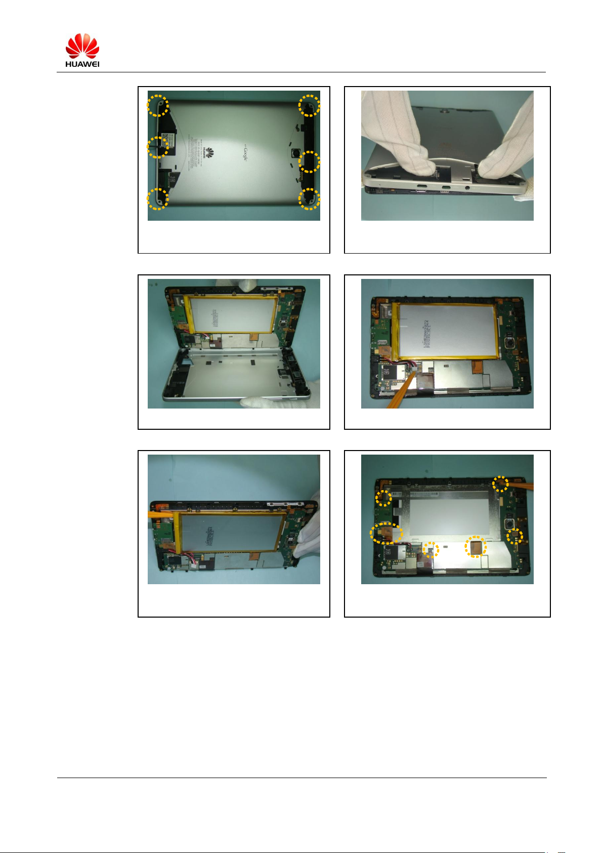
5.
Remove the six screws on the rear
cover.
6.
Unlock the rear cover.
7.
Disassemble the rear cover.
8.
Loosen the BTB connector of the battery.
9.
Take out the glued battery.
10.
Loosen the BTB connector marked in the
picture.
S7-PRO Maintenance Manual (Basic Version V2.1)
INTERNAL
2012-07-20
Huawei Proprietary and Confidential
Copyright © Huawei Technologies Co., Ltd.
Page 30 of 97
11.
Remove the 5-megapixel camera.
12.
Loosen the BTB connector of the headset.
13.
Remove the JACK FPC of the headset.
14.
Remove the screws marked in the picture.
15.
Remove the connector of the headset.
16.
Remove the auxiliary board.

S7-PRO Maintenance Manual (Basic Version V2.1)
INTERNAL
2012-07-20
Huawei Proprietary and Confidential
Copyright © Huawei Technologies Co., Ltd.
Page 31 of 97
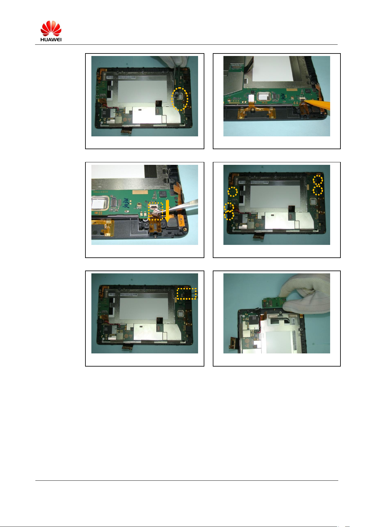
17.
Remove the three screws on the main
board.
18.
Remove the conductive fabric between
the main board and the LCD support.
19.
Remove the main board.
20.
Remove the FPCs marked in the picture.
21.
Remove the seven screws securing the
LCD.
22.
Remove the LCD from other cover A
assembly.

S7-PRO Maintenance Manual (Basic Version V2.1)
INTERNAL
2012-07-20
Huawei Proprietary and Confidential
Copyright © Huawei Technologies Co., Ltd.
Page 32 of 97
23.
Place the protective film on the LCD.
24.
Place the protective film on the lens.
25.
Remove the speaker on the rear cover.
26.
Remove the vibrator on the rear cover.
27.
Remove the front camera.

S7-PRO Maintenance Manual (Basic Version V2.1)
INTERNAL
2012-07-20
Huawei Proprietary and Confidential
Copyright © Huawei Technologies Co., Ltd.
Page 33 of 97
8 Assembly Procedures
1.
Ensure that the ESD wrist strap is
properly grounded.
2.
Remove the protective film on the lens.
3.
Remove the protective film on the LCD.
4.
Install the LCD.
5.
Tighten the screws marked in the picture
to secure the LCD.
6.
Place FPCs at the positions marked in the
picture.

S7-PRO Maintenance Manual (Basic Version V2.1)
INTERNAL
2012-07-20
Huawei Proprietary and Confidential
Copyright © Huawei Technologies Co., Ltd.
Page 34 of 97
7.
Install the front camera to the main
board.
8.
Install the main board.
9.
Place the conductive fabric at the
position marked in the picture.
10.
Tighten the screws marked in the picture
to secure the main board.
11.
Install the auxiliary board.
12.
Install the connector of the headset.

S7-PRO Maintenance Manual (Basic Version V2.1)
INTERNAL
2012-07-20
Huawei Proprietary and Confidential
Copyright © Huawei Technologies Co., Ltd.
Page 35 of 97
13.
Tighten the screws marked in the
picture.
14.
Install the FPC for the connector of the
headset.
15.
Secure the BTB connector of the
headset.
16.
Install the rear camera.
17.
Secure the BTB connectors marked in
the picture.
18.
Install the battery.

S7-PRO Maintenance Manual (Basic Version V2.1)
INTERNAL
2012-07-20
Huawei Proprietary and Confidential
Copyright © Huawei Technologies Co., Ltd.
Page 36 of 97
19.
Secure the connector of the battery.
20.
Install the vibrator.
21.
Install the speakers.
Note:
The springs of them must face each other.
22.
Install the rear cover.
23.
Secure the front cover and rear cover.
24.
Tighten the screws on the rear cover.

S7-PRO Maintenance Manual (Basic Version V2.1)
INTERNAL
2012-07-20
Huawei Proprietary and Confidential
Copyright © Huawei Technologies Co., Ltd.
Page 37 of 97
25.
Install the lower decorative cover.
26.
Install the upper decorative cover.
9 Troubleshooting for Common Failures
9.1 Principle
The S7 Pro, customized for home and mobile users, provides high-speed radio interface
(WCDMA, WIFI) for access to the Broadband Metropolitan Area Network (BMAN), and
HDMI to support various multimedia formats. The S7 Pro supports multimedia, games, GPS,
IM, audio, and data communication to provide satisfactory entertainment and communication
services to home and mobile users. The S7 Pro uses a single board to control the device, and
process the graph, image, and baseband signal.
The key components of Mediapad include: processor MSM8260, RF transceiver QTR8615,
PMU PM8058 and PM8901, power management IC MAX8903, WLAN/BT module
BCM4329, and RGB to LVDS 8-bit transceiver.
The MSM8260 is Qualcomm's new generation processor, and mainly includes the following
sub-processors:
Apps processing: two Scorpion cores, with combined L2 (512 kB) cache running at up to 1.2
GHz
Applications DSP: QDSP6 processor (565 MHz)
Modem μP: ARM1136™ + L2 cache (256 kB) at up to 384 MHz
Modem DSP: QDSP4 processor (to 147 MHz)
Resource power manager: ARM7 (54 MHz)
Sensor peripheral subsystem (SPSS): ARM7 (64 MHz)
Characteristics of the chip:

S7-PRO Maintenance Manual (Basic Version V2.1)
INTERNAL
2012-07-20
Huawei Proprietary and Confidential
Copyright © Huawei Technologies Co., Ltd.
Page 38 of 97
For baseband processing, it supports the UMTS (WCDMA), HSPA+, and
GSM/GPRS/EDGE.
The AP processing speed o is up to 1.2 GHz; the 256 MHz ARM1136 P modem processor and
the 122 MHz QDSP4 DSP are used.
For storage, it supports the LPDDR2 SDRAM (Pro Via EBI1), NAND flash, OneNAND, and
NOR flash.
ISM — 32-bit LPDDR2 SDRAM up to 333 MHz (64 MB) for multimedia
EBI1 support — 32-bit LPDDR2 SDRAM up to 266 MHz (512 MB as a minimum)
SD support — eMMC NAND flash (The versions of eMMC BOOT and eMMC on the board
must be version 4.4 or later versions).
Camera connectors: Qcamera™ Feature
Rear camera (via 4-lane MIPI_CSI) — support the CMOS and CCD sensors; 16 megapixel as
a maximum.
Front camera (via 2-lane MIPI_CSI) — support the CMOS and CCD sensors; 12 megapixel
as a maximum; maximum resolution: WSXGA 1440 x 900; supports up to three displays.
Primary: 4-lane MIPI_DSI – up to 24-bit WSXGA (1440 x 900); refresh rate up to 60 Hz
Secondary: RGB interface – up to WSXGA (1440 x 900); refresh rate up to 60 Hz
Tertiary: EBI2 interface – up to 400 x 240, non-active refresh
Color depth: 24 bits per pixel (bpp)
Audio/video (A/V) output
---»Composite video plus line audio for NTSC/PAL TVs
---»S -video plus line audio for NTSC/PAL TVs
---»High Definition Multimedia Interface (HDMI) Ver. 1.3
---»Integrated HDMI Tx core and HDMI PHY
---»1080p with a refresh rate of 60 Hz; 24-bit RGB color
---» Up to 8-channel audio for 7.1 surround sound
--»Dolby® Digital Plus, Dolby True-HD, and DTS-HD Master
Video decoding (Windows Mobile and Linux) supports the following:
Program source: 30 fps at 1080p (H.264/MPEG2/MPEG4/DivX/VC-1), 30 fps at D1
(H.263)
Video source: 30 fps at 1080p (H.264/MPEG2/MPEG4/DivX/VC-1), 30 fps at D1
(H.263)
Video calling: 15 fps at QCIF (MPEG4/H.263)
Audio codec via the QTR8615 or QTR9215 device
External interfaces:
---»UART ports, UIM ports, I2C ports, and SPI ports (master only);
---»USB interfaces: HS USB 2.0 OTG with built-in USB PHY, FS USB (without built-in
USB PHY), and USB-UICC

S7-PRO Maintenance Manual (Basic Version V2.1)
INTERNAL
2012-07-20
Huawei Proprietary and Confidential
Copyright © Huawei Technologies Co., Ltd.
Page 39 of 97
---»Secure digital interfaces: up to five ports, MMC and SD cards, eMMC NAND flash,
UBM and WLAN, and SD/eMMC boot
---»I2S interfaces: up to 18 multiple I2S channels over five interfaces
---»PCM: for Bluetooth
---»TSIF: up to two ports
---»NFC: with external NFC device
The MSM8260 functional block diagram is shown in the following figures.

S7-PRO Maintenance Manual (Basic Version V2.1)
INTERNAL
2012-07-20
Huawei Proprietary and Confidential
Copyright © Huawei Technologies Co., Ltd.
Page 40 of 97
9.2 Power-on Failure
The following three conditions must be met to power the PRO on:
1. Press and hold the Power button for two seconds with the battery in place.
2. Connect the 5 V DC regulated power supply to the DC power interface with the battery
in place. The device is powered on, and charging begins.
3. Connect the 5 V DC regulated power supply to the DC power interface with the battery
not in place. The device is powered on and starts to run.
Connect the DC adapter to the power-on circuits.

S7-PRO Maintenance Manual (Basic Version V2.1)
INTERNAL
2012-07-20
Huawei Proprietary and Confidential
Copyright © Huawei Technologies Co., Ltd.
Page 41 of 97
Power_key circuit:

S7-PRO Maintenance Manual (Basic Version V2.1)
INTERNAL
2012-07-20
Huawei Proprietary and Confidential
Copyright © Huawei Technologies Co., Ltd.
Page 42 of 97
NOTE
Mediapad power-on sequence:
Standard sequence:
VREG_S0A--->VREG_S1A--->VREG_S3A--->VREG_S2A--->VREG_L0A--->VREG_L21
A--->VREG_L7A--->VREG_L13A--->VREG_L16A--->VREG_L5A--->VREG_L6A--->VR
EG_S0B--->VREG_S3B--->VREG_L3B--->VREG_L11A--->--->TP_3V3--->VREG_L4B
1. VDD_MEM (internal memory)
2. VDD_C1 (digital core circuits)
3. VDD_ISM1 and VDD_P3 (ISM 1.8 V power and most pad circuits/peripheral I/Os
respectively)
4. VDD_A3 (1.3 V RF, GPS ADC)
5. VDD_A2 (MIPI-DSI display)
6. VDD_A1, VDD_PXO, and VDD_MXO (PLLs, PXO, and MXO crystal power
respectively)
7. VDD_USBPHY_1P8 (1.8 V USB supply)
8. VDD_A5 (DACs and BBRx)
9. VDD_A4; VDD_A4_GPLL and VDD_A4_HFPLL (HDMI and MIPI-CSI; PLLs)
10. VDD_P2 (2.85 V SD card)
11. VDD_USBPHY_3P3 (3.3 V USB supply)
12. VDD_SC1 (1.1 V Scorpion core 1 – optional)
1. The core voltage (VDD_C1) needs to be powered up before the pad circuits
(VDD_PX) are powered up, so that internal circuits can take control of the I/Os and
pads.
2. If pad voltages are powered up first, the output drivers may be stuck in unknown
states, and may cause high leakage current until VDD_C1 is powered on.
3. The pad voltages must precede the analog voltages (VDD_AX), because the SSBIs
are initialized to the default state before VDD_AX is powered up (analog circuits are
controlled by SSBI).
4. VDD_QDSP, VDD_SC1, and VDD_SC2 (QDSP and Scorpion core circuits) can be
powered up by the software after the MSM device has completed the boot process.
5. Other non-critical supplies are included in the power-up sequence. Any other desired
supplies can be powered up by software after the sequence is completed.
6. Each domain needs to reach the 90% value before the next domain starts ramping up.
For example, when VDD_C1 reaches 90% of the specified value, the VDD_P3 supply
can start ramping up.

S7-PRO Maintenance Manual (Basic Version V2.1)
INTERNAL
2012-07-20
Huawei Proprietary and Confidential
Copyright © Huawei Technologies Co., Ltd.
Page 43 of 97
NOTE
NOTE
VDD_QFUSE_PRG must be powered down before any of the pad power supplies are powered down
The VDD_QFUSE_PRG pin should be connected to a 1.8 V power supply only for blowing fuses;
otherwise, this pin must be grounded and never be left floating.
The kernel system power-on waveform is shown in the following figure.

S7-PRO Maintenance Manual (Basic Version V2.1)
INTERNAL
2012-07-20
Huawei Proprietary and Confidential
Copyright © Huawei Technologies Co., Ltd.
Page 44 of 97
Voltage:

S7-PRO Maintenance Manual (Basic Version V2.1)
INTERNAL
2012-07-20
Huawei Proprietary and Confidential
Copyright © Huawei Technologies Co., Ltd.
Page 45 of 97
Type/Name
Default
Conditions
Programmable
Range
Operating
Range
Intended Use
SMPS – Buck
S0 (1.5 A) 2 3
S1 (1.5 A)
S2 (1.5 A)
S3 (1.5 A)
S4 (1.5 A)
On, 1.100 V
On, 1.100 V
Off, 1.350 V
On, 1.800 V
Off, 2.200 V
0.375 to 3.05 V
0.375 to 3.05 V
0.375 to 3.05 V
0.375 to 3.05 V
0.375 to 3.05 V
0.500 to 1.350 V
0.500 to 1.350 V
0.500 to 1.500 V
1.700 to 1.900 V
2.100 to 2.400 V
Processor core #1
Processor core #2 (if available)
Low-voltage RF circuits
Digital pads and EBI
High-voltage RF circuits
Linear – 300 mA
L1 (NMOS)
L2 (PMOS)
L5 (PMOS)
L8 (PMOS)
L9 (PMOS)
L10 (PMOS)
L13 (PMOS)
L14 (PMOS)
L15 (PMOS)
L16 (PMOS)
L22 (NMOS)
L23 (NMOS)
On, 1.350 V
Off
On, 2.850 V
Off, 2.200 V
Off, 2.100 V
Off, 2.600 V
Off, 2.900 V
Off, 2.850 V
Off, 2.850 V
Off, 1.800 V
Off, 1.200 V
Off, 1.200 V
0.75 to 1.525 V
1.5 to 3.3 V
1.5 to 3.3 V
1.5 to 3.3 V
1.5 to 3.3 V
1.5 to 3.3 V
1.5 to 3.3 V
1.5 to 3.3 V
1.5 to 3.3 V
1.5 to 3.3 V
0.75 to 1.525 V
0.75 to 1.525 V
1.100 to 1.450 V
2.500 to 3.3 V
2.750 to 3.3 V
1.500 to 3.3 V
1.500 to 3.3 V
1.500 to 3.3 V
1.500 to 3.3 V
1.500 to 3.3 V
1.500 to 3.3 V
1.500 to 3.3 V
1.000 to 1.400 V
1.000 to 1.400 V
DDR2 core (EBI1), HSIC, digital
I/Os
Digital pads; Tx DAC; XO digital
outputs
SDIO
Analog and RF circuits; S-video;
combo DAC
Analog baseband circuits; S-video
DAC
UBM analog; MDDI; NCP
WLAN PA
RF front-end circuits
LCD
Multimedia controls
General-purpose
General-purpose
Linear – 150 mA
L0 (NMOS)
L3 (PMOS)
L11 (PMOS)
L12 (PMOS)
L17 (PMOS)
L18 (PMOS)
L19 (PMOS)
L20 (PMOS)
L21 (NMOS)
L24 (NMOS)
L25 (NMOS)
On, 1.200 V
Off
Off, 2.800 V
Off, 2.900 V
Off, 2.200 V
Off, 2.200 V
Off, 2.500 V
Off, 1.500 V
On, 1.100 V
Off, 1.300 V
Off, 1.300 V
0.75 to 1.525 V
1.5 to 3.3 V
1.5 to 3.3 V
1.5 to 3.3 V
1.5 to 3.3 V
1.5 to 3.3 V
1.5 to 3.3 V
1.5 to 3.3 V
0.75 to 1.525 V
0.75 to 1.525 V
0.75 to 1.525 V
1.100 to 1.300 V
1.700 to 3.3 V
1.500 to 3.3 V
1.500 to 3.3 V
1.500 to 3.3 V
2.100 to 3.3 V
1.500 to 3.3 V
1.500 to 3.3 V
1.000 to 1.400 V
1.000 to 1.400 V
1.000 to 1.400 V
DDR2; digital I/Os; HDMI; UBM
digital
UIM/UICC
Camera analog
NFC; RF front-end circuits
General-purpose
ADCs (XO, HK, TS, UBM)
WLAN analog
MDDI; multimedia controls
MPLL circuits
General-purpose
General-purpose
Linear – 50 mA
L4 (PMOS)4
L6 (PMOS)
L7 (PMOS)
On, 2.850 V
On, 3.075 V
On, 1.800 V
1.5 to 3.3 V
1.5 to 3.6 V
1.5 to 3.3 V
2.750 to 3.3 V
2.950 to 3.6 V
1.750 to 3.3 V
XO circuits and sine wave output
buffers
USB PHY; HDMI
USB PHY; RF XO circuits; PA
DAC; Q-fuse

S7-PRO Maintenance Manual (Basic Version V2.1)
INTERNAL
2012-07-20
Huawei Proprietary and Confidential
Copyright © Huawei Technologies Co., Ltd.
Page 46 of 97
Type/Name
Default
Conditions
Programmable
Range
Operating
Range
Intended Use
Low-voltage
Switches
LVS0 (100 mA)
LVS1 (100 mA)
Off, 1.800 V
Off, 1.800 V
Not applicable
Not applicable
Not applicable
Not applicable
Camera
Sensors, HDMI
NCP (200 mA)
Off, –1.800 V
–1.700 to –1.900
V
–1.700 to –1.900 V
Headset circuits

S7-PRO Maintenance Manual (Basic Version V2.1)
INTERNAL
2012-07-20
Huawei Proprietary and Confidential
Copyright © Huawei Technologies Co., Ltd.
Page 47 of 97
9.2.1 Power-on Failure — High Current
Analysis: Adjust the DC regulated power supply to 5 V/3 A, and connect it to the PRO_DC
interface for power-on. When the device is powered on, the current exceeds 500 mA. In this
case, the power-on failure is usually caused by improper SMT or IC damage. For the
maintenance procedures, see Figure 9-1, Figure 9-2, and Figure 9-3.

S7-PRO Maintenance Manual (Basic Version V2.1)
INTERNAL
2012-07-20
Huawei Proprietary and Confidential
Copyright © Huawei Technologies Co., Ltd.
Page 48 of 97
Power-on fails due to high
current
Switch off the power and check
whether short circuit occurs in
C665 and C624
Check whether short circuit
occurs in the C418/C419/C420/
C423/C424
Check whether short circuit
occurs in C442, C435, C444, and
C445
Replace U2
Yes
No
No
No
Replace U48
Replace U7
Replace U2
Yes
Yes

S7-PRO Maintenance Manual (Basic Version V2.1)
INTERNAL
2012-07-20
Huawei Proprietary and Confidential
Copyright © Huawei Technologies Co., Ltd.
Page 49 of 97
Figure 9-1

S7-PRO Maintenance Manual (Basic Version V2.1)
INTERNAL
2012-07-20
Huawei Proprietary and Confidential
Copyright © Huawei Technologies Co., Ltd.
Page 50 of 97
Figure 9-2
Figure 9-3
9.2.2 Power-on Failure — Low Current
Analysis: Adjust the DC regulated power supply to 5 V/3 A, and connect it to the PRO_DC
interface for power-on. When the device is powered on, the current is below 70 mA. In this
case, the power-on failure is usually caused by improper eMMC programming or SMT. For
the maintenance procedures, see Figure 9-1, Figure 9-2, and Figure 9-3.

S7-PRO Maintenance Manual (Basic Version V2.1)
INTERNAL
2012-07-20
Huawei Proprietary and Confidential
Copyright © Huawei Technologies Co., Ltd.
Page 51 of 97
Power-on fails due to low current
Check the U48 output and
measure whether the voltage
difference between C665 and
C624 is 4.2 V
Check the U7 output and measure
whether the voltage difference
between C418 and C419 is 1.8 V
Perform eMMC programming
again (U12)
No
Yes
Yes
Replace U48
Replace U7No
9.3 Charge Failure
The Mediapad charging management circuits are shown in the following figure.
Principle: The DC regulated power supply provides the 5 V/3 A power supply to the DC-DC
circuits in the MAX8903, and MAX8903 and the power is output through VBAT and
VPH_PWR respectively.
Analysis: The U48 manages the charging of S7 Pro. For the maintenance procedures upon
charge failure, see the Appendix 1 (diagram of PRO components).

S7-PRO Maintenance Manual (Basic Version V2.1)
INTERNAL
2012-07-20
Huawei Proprietary and Confidential
Copyright © Huawei Technologies Co., Ltd.
Page 52 of 97
Charging fails
Check whether the voltage
difference among D3, D20, C747,
C486, and C108 is 5 V
Measure the R4 voltage
difference and check for improper
SMT
Solder R4
No
Yes
Yes
Replace D3, D20, C747,
C486, and C108
Replace U48No
9.4 Failure to Identify SIM Card
Diagram of the circuits:
The SIM_CD indicates the PIN of the SIM card and is used for identifying the SIM card.
When the SIM card is inserted, the voltage of SIM_CD changes from a high level to a low
level.
Remark: For the maintenance procedures, see Appendix 1 (diagram of PRO components).
Perform the eMMC programming again (U12).

S7-PRO Maintenance Manual (Basic Version V2.1)
INTERNAL
2012-07-20
Huawei Proprietary and Confidential
Copyright © Huawei Technologies Co., Ltd.
Page 53 of 97
SIM card identification fails.
Check whether the device
enters the airplane mode when
it is powered on
Check whether the voltage of
C591 ranges from 1.8 V to 3.3 V
Perform the eMMC programming
again (U12)
Yes
No
No
Set the device to non-
airplane mode
Replace Z12Yes

S7-PRO Maintenance Manual (Basic Version V2.1)
INTERNAL
2012-07-20
Huawei Proprietary and Confidential
Copyright © Huawei Technologies Co., Ltd.
Page 54 of 97
9.5 Failure to Identify SD Card
Diagram of the circuits:

S7-PRO Maintenance Manual (Basic Version V2.1)
INTERNAL
2012-07-20
Huawei Proprietary and Confidential
Copyright © Huawei Technologies Co., Ltd.
Page 55 of 97
The SDC3_CARA_CD indicates PIN of the SD card and is used for identifying the SD card.
When the SD card is inserted, the voltage of SDC3_CARA_CD changes from a high level to
a low level. The MSM8260 determines that the SD card is available. Then call the SD card
driver to access the SD card.

S7-PRO Maintenance Manual (Basic Version V2.1)
INTERNAL
2012-07-20
Huawei Proprietary and Confidential
Copyright © Huawei Technologies Co., Ltd.
Page 56 of 97

S7-PRO Maintenance Manual (Basic Version V2.1)
INTERNAL
2012-07-20
Huawei Proprietary and Confidential
Copyright © Huawei Technologies Co., Ltd.
Page 57 of 97
SD card identification fails
Check whether the voltage of
C514 on the main board
(PCB) is 2.85 V
Check whether the voltage of R4
on the auxiliary board is 2.85 V
Repair the auxiliary board
No
Yes
Yes
Replace U7
Replace the FPC connecting the
main board PCB and auxiliary
board PCB
No
Check whether short circuit to
ground occurs in R10, R9, R12,
R13, and R8 on the auxiliary
PCB
Yes
Replace the SD card socketNo

S7-PRO Maintenance Manual (Basic Version V2.1)
INTERNAL
2012-07-20
Huawei Proprietary and Confidential
Copyright © Huawei Technologies Co., Ltd.
Page 58 of 97
9.6 Display Failure
LCD driver circuits:
LCD backlight driver circuits:

S7-PRO Maintenance Manual (Basic Version V2.1)
INTERNAL
2012-07-20
Huawei Proprietary and Confidential
Copyright © Huawei Technologies Co., Ltd.
Page 59 of 97
Principles:
SN75LVDS83BZQLR is used as the RGB to LVDS transmitter for T1, having the following
characteristics:
LVDS display SerDes interfaces directly to LCD display panels with integrated LVDS
1.8 V up to 3.3 V tolerant data inputs to connect directly to low-power, low-voltage
application and graphic processors
Transfer rate up to 135 Mpps (mega pixel per second); pixel clock frequency range: 10
MHz to 135 MHz
Operates from a single 3.3 V supply and 170 mW (typ.) at 75 MHz
28 data channels plus clock in low-voltage TTL to 4 data channels plus clock out
low-voltage differential
Consumes less than 1 mW when disabled
The block diagram of SN75LVDS83BZQLR is shown in the following figure.
Remark 1: Although the backlight can be turned on, no image is displayed. See the following
chart for maintenance procedures.

S7-PRO Maintenance Manual (Basic Version V2.1)
INTERNAL
2012-07-20
Huawei Proprietary and Confidential
Copyright © Huawei Technologies Co., Ltd.
Page 60 of 97
Display failure (no image) occurs
Check whether short circuit occurs in U40 Yes
No
Replace U40
Replace the LCD
Display failure occurs (the
backlight cannot be turned on)
Check whether short circuit
occurs in U1
Check whether short circuit
occurs in Q22
Yes
No
No
Replace U1
Replace Q22Yes
Check whether J9 shows any
insufficient or staggered soldering
No
Repair J9Yes
Replace the LCD
Remark 2: The backlight cannot be turned on. See the following chart for maintenance
procedures.
9.7 Touchscreen Failure
Diagram of circuits:

S7-PRO Maintenance Manual (Basic Version V2.1)
INTERNAL
2012-07-20
Huawei Proprietary and Confidential
Copyright © Huawei Technologies Co., Ltd.
Page 61 of 97
Touchscreen failure occurs
Check whether short circuit occurs in U1000
Check whether short circuit occurs in U35
Yes
No
No
Replace U1000
Replace U35Yes
Check whether short circuit occurs in U19
No
Replace U19Yes
Replace the TP (touchscreen)
Principle: The Mediapad power-on system loads the touchscreen driver through the I2C port.
See the following chart for maintenance procedures.
9.8 Audio Failure
9.8.1 Speaker Failure
Diagram of circuits:

S7-PRO Maintenance Manual (Basic Version V2.1)
INTERNAL
2012-07-20
Huawei Proprietary and Confidential
Copyright © Huawei Technologies Co., Ltd.
Page 62 of 97
Speaker failure occurs
Check whether short circuit
occurs in U14 and U15
Check whether short circuit
occurs in SKP
Yes
No
No
Replace U14 and U15
Replace the SPKYes
Replace the SPK-FPC
In the case of no sound from the speaker, check for sound output after the S7 Pro is connected
to the TV through the HDMI. If there is sound, repair the device according to the following
chart.

S7-PRO Maintenance Manual (Basic Version V2.1)
INTERNAL
2012-07-20
Huawei Proprietary and Confidential
Copyright © Huawei Technologies Co., Ltd.
Page 63 of 97
9.8.2 Headset Failure
Diagram of circuits:
Upon a headset failure, check whether the headset interface is properly assembled. If the
problem persists, replace the headset jack.
9.9 Camera Failure
Diagram of circuits:
The S7 Pro camera transmits signals through the MIPI. The red part indicates the power
supply circuit of the camera.
See the following chart for maintenance procedures.

S7-PRO Maintenance Manual (Basic Version V2.1)
INTERNAL
2012-07-20
Huawei Proprietary and Confidential
Copyright © Huawei Technologies Co., Ltd.
Page 64 of 97
Camera failure occurs
Check whether the voltage of C246
and C247 is 1.8 V, and whether the
voltage of C248 and 249 is 2.8 V
Visually check for any improper SMT
in J2 and J6
No
Yes
Yes
Replace U7
Repair J2 and J6No
Replace the camera
9.10 Vibration Failure
Diagram of circuits:
Principle: The motor controls the vibration based on the differential pressure of the input PIN.

S7-PRO Maintenance Manual (Basic Version V2.1)
INTERNAL
2012-07-20
Huawei Proprietary and Confidential
Copyright © Huawei Technologies Co., Ltd.
Page 65 of 97
Vibration failure occurs
The motor becomes faulty No
Yes
Replace the motor PFC
Replace the motor
9.11 RF Failure
Figure 9-4 Block diagram of QTR8615 RF

S7-PRO Maintenance Manual (Basic Version V2.1)
INTERNAL
2012-07-20
Huawei Proprietary and Confidential
Copyright © Huawei Technologies Co., Ltd.
Page 66 of 97
As shown in the block diagram, the transmitter includes high frequency, intermediate
frequency, and low frequency channels. The IQ signal is transmitted to the built-in power
amplifier through the up-converter. The AGC is used to control the power output, and the
AGC circuit includes a power detector to achieve a transmit power control range greater than
85 dB. The output radio frequency signal is sent to the front-end module, and transmitted by
the antenna to QTR8615. After the signal is amplified in the internal LNA, it is
down-converted to I/Q baseband signal.
The device supports WCDMA that uses the frequency band of 5 MHz and GSM that uses the
frequency band of 4 MHz.
Figure 9-5 Diagram of circuits of the RF antenna switch
The red part indicates that the signal is transmitted into the antenna switch (U46) through the
transmit channel, and the blue part indicates that the signal is transmitted out of U46 through
the receive channel.
Figure 9-6 Diagram of circuits of WCDMA2100 RF channels
The red part indicates the transmit channel, and the blue part indicates the receive channel.
Both the transmit channel and the receive channel are connected to the antenna switch
through the duplexer (U20).

S7-PRO Maintenance Manual (Basic Version V2.1)
INTERNAL
2012-07-20
Huawei Proprietary and Confidential
Copyright © Huawei Technologies Co., Ltd.
Page 67 of 97
Figure 9-7 Diagram of circuits of WCDMA1900 RF channels
The red part indicates the transmit channel, and the blue part indicates the receive channel.
Both the transmit channel and the receive channel are connected to the antenna switch
through the duplexer (U41).
Figure 9-8 Diagram of circuits of WCDMA AWS RF channels
The red part indicates the transmit channel, and the blue part indicates the receive channel.
Both the transmit channel and the receive channel are connected to the antenna switch
through the duplexer (U31).
Figure 9-9 Diagram of circuits of WCDMA850 RF channels

S7-PRO Maintenance Manual (Basic Version V2.1)
INTERNAL
2012-07-20
Huawei Proprietary and Confidential
Copyright © Huawei Technologies Co., Ltd.
Page 68 of 97
The red part indicates the transmit channel, and the blue part indicates the receive channel.
Both the transmit channel and the receive channel are connected to the antenna switch
through the duplexer (U21).
Figure 9-10 Diagram of circuits of WCDMA900 RF channels
The red part indicates the transmit channel, and the blue part indicates the receive channel.
Both the transmit channel and the receive channel are connected to the antenna switch
through the duplexer (U32).
Figure 9-11 Diagram of circuits of GSM transmit channels
The green part indicates the GSM HB channel, and the blue part indicates the GSM LB
channel.

S7-PRO Maintenance Manual (Basic Version V2.1)
INTERNAL
2012-07-20
Huawei Proprietary and Confidential
Copyright © Huawei Technologies Co., Ltd.
Page 69 of 97
9.12 Maintenance Procedures for Transmit Failure
Y
Check the input power of QTR8615
End
Check whether the 19.2
MHz crystal (X1) is
normal
Power on the
board
Maintenance procedures
No
No
No
No
No
No
Check whether QTR8615 can
output the signal TX_IMT
normally
Check whether the power
supply for QTR8615 (U23) is
normal
Check whether the power output
of the power amplifier (U22) is
within the specified range
Check whether the duplexer
(U20) works normally
Check whether the antenna
switch (U46) works normally
Replace QTR8615 (U23)
Check the input signal, output signal, and
power supply. If any exception is found,
replace the power amplifier (U22)
Replace the duplexer (U20)
Check the input signal, output signal,
logic control signal, and power supply.
If any exception is found, replace U46
Replace X1
Yes
Yes
Yes
Yes
Yes
Yes
9.12.1 WCMDA2100 Transmit Calibration Failure

S7-PRO Maintenance Manual (Basic Version V2.1)
INTERNAL
2012-07-20
Huawei Proprietary and Confidential
Copyright © Huawei Technologies Co., Ltd.
Page 70 of 97
9.12.2 WCMDA1900 Transmit Calibration Failure
Y
Check the input power of QTR8615
End
Check whether the 19.2
MHz crystal (X1) is
normal
Power on the
board
Maintenance procedures
No
No
No
No
No
No
Check whether QTR8615 can
output the signal TX_PCS
normally
Check whether the power
supply for QTR8615 (U23) is
normal
Check whether the power output
of the power amplifier (U24) is
within the specified range
Check whether the duplexer
(U41) works normally
Check whether the antenna
switch (U46) works normally
Replace QTR8615 (U23)
Check the input signal, output signal, and
power supply. If any exception is found,
replace the power amplifier (U24)
Replace the duplexer (U41)
Check the input signal, output signal,
logic control signal, and power supply.
If any exception is found, replace U46
Replace X1
Yes
Yes
Yes
Yes
Yes
Yes

S7-PRO Maintenance Manual (Basic Version V2.1)
INTERNAL
2012-07-20
Huawei Proprietary and Confidential
Copyright © Huawei Technologies Co., Ltd.
Page 71 of 97
9.12.3 AWS Transmit Calibration Failure
Y
Check the input power of QTR8615
End
Check whether the 19.2
MHz crystal (X1) is
normal
Power on the
board
Maintenance procedures
No
No
No
No
No
No
Check whether QTR8615 can
output the signal TX_PCS
normally
Check whether the power
supply for QTR8615 (U23) is
normal
Check whether the power output
of the power amplifier (U25) is
within the specified range
Check whether the duplexer
(U31) works normally
Check whether the antenna
switch (U46) works normally
Replace QTR8615 (U23)
Check the input signal, output signal, and
power supply. If any exception is found,
replace the power amplifier (U25)
Replace the duplexer (U31)
Check the input signal, output signal,
logic control signal, and power supply.
If any exception is found, replace U46
Replace X1
Yes
Yes
Yes
Yes
Yes
Yes

S7-PRO Maintenance Manual (Basic Version V2.1)
INTERNAL
2012-07-20
Huawei Proprietary and Confidential
Copyright © Huawei Technologies Co., Ltd.
Page 72 of 97
9.12.4 WCMDA850 Transmit Calibration Failure
Y
Check the input power of QTR8615
End
Check whether the 19.2
MHz crystal (X1) is
normal
Power on the
board
Maintenance procedures
No
No
No
No
No
No
Check whether QTR8615 can
output the signal TX_850
normally
Check whether the power
supply for QTR8615 (U23) is
normal
Check whether the power output
of the power amplifier (U44) is
within the specified range
Check whether the duplexer
(U21) works normally
Check whether the antenna
switch (U46) works normally
Replace QTR8615 (U23)
Check the input signal, output signal, and
power supply. If any exception is found,
replace the power amplifier (U44)
Replace the duplexer (U21)
Check the input signal, output signal,
logic control signal, and power supply.
If any exception is found, replace U46
Replace X1
Yes
Yes
Yes
Yes
Yes
Yes

S7-PRO Maintenance Manual (Basic Version V2.1)
INTERNAL
2012-07-20
Huawei Proprietary and Confidential
Copyright © Huawei Technologies Co., Ltd.
Page 73 of 97
9.12.5 WCMDA900 Transmit Calibration Failure
Y
Check the input power of QTR8615
End
Check whether the 19.2
MHz crystal (X1) is
normal
Power on the
board
Maintenance procedures
No
No
No
No
No
No
Check whether QTR8615 can
output the signal TX_U900
normally
Check whether the power
supply for QTR8615 (U23) is
normal
Check whether the power
output of the power amplifier
(U29) is within the specified
Check whether the antenna
switch (U46) works normally
Check whether the antenna
switch (U46) works normally
Replace QTR8615 (U23)
Check the input signal, output signal, and
power supply. If any exception is found,
replace the power amplifier (U29)
Replace the duplexer (U32)
Check the input signal, output signal,
logic control signal, and power supply.
If any exception is found, replace U46
Replace X1
Yes
Yes
Yes
Yes
Yes
Yes

S7-PRO Maintenance Manual (Basic Version V2.1)
INTERNAL
2012-07-20
Huawei Proprietary and Confidential
Copyright © Huawei Technologies Co., Ltd.
Page 74 of 97
9.12.6 GSM HB Transmit Calibration Failure
Y
Check the input power of QTR8615
End
No
Check whether the
power supply for
QTR8615 (U23)
Replace X1
Replace QTR8615 (U23)
Check the input signal, output signal, and
power supply. If any exception is found,
replace the power amplifier (U47)
No
Yes
Check whether QTR8615
can output the signal
TX_GSM_LB normally
Check whether the
19.2 MHz crystal
(X1) is normal
Check whether the
TX_DCS1800_PCS19 power
output of the power amplifier (U47)
No
Yes
No
Power on the
board
Yes
Check whether the antenna switch
(U46) works normally
Check the input signal, output signal,
logic control signal, and power
supply. If any exception is found,
replace U46
Maintenance procedures
Yes
Yes
No

S7-PRO Maintenance Manual (Basic Version V2.1)
INTERNAL
2012-07-20
Huawei Proprietary and Confidential
Copyright © Huawei Technologies Co., Ltd.
Page 75 of 97
9.12.7 GSM LB Transmit Calibration Failure
Y
Check the input power of QTR8615
End
No
Check whether the power
supply for QTR8615
(U23) is normal
Replace X1
Replace QTR8615 (U23)
Check the input signal, output signal, and
power supply. If any exception is found,
replace the power amplifier (U47)
No
Yes
Check whether QTR8615
can output the signal
TX_GSM_LB normally
Check whether the
19.2 MHz crystal
(X1) is normal
Check whether the
TX_GSM850_EGSM9 power
output of the power amplifier (U47)
No
Yes
No
Power on the
board
Yes
Check whether the antenna
switch (U46) works normally
Check the input signal, output signal,
logic control signal, and power
supply. If any exception is found,
replace U46
Maintenance procedures
Yes
Yes
No

S7-PRO Maintenance Manual (Basic Version V2.1)
INTERNAL
2012-07-20
Huawei Proprietary and Confidential
Copyright © Huawei Technologies Co., Ltd.
Page 76 of 97
9.13 Maintenance Procedures for Receiving Failure
Yes
No
Y
Replace U20, U41 U31, U21, and U32
Check the input signal, output signal,
logic control signal, and power supply.
If any exception is found, replace U46
Check whether the antenna switch
(U46) and the WCDMA receive
channel work normally
No
Y
No
Check the power supply for U23. If any
exception is found, replace U23
Check whether the input and
output signals of duplexers
(U20, U41, U31, U21, and
U32) are normal
Power the board
on
End
Yes
Check whether
QTR8615 (U23) works
normally
Maintenance procedures
Yes
9.13.1 Maintenance Procedures for WCDMA Receiving Failure

S7-PRO Maintenance Manual (Basic Version V2.1)
INTERNAL
2012-07-20
Huawei Proprietary and Confidential
Copyright © Huawei Technologies Co., Ltd.
Page 77 of 97
9.13.2 Maintenance Procedures for GSM Receive Failure
Yes
No
Y
Replace U21
Check the input signal, output signal,
logic control signal, and power supply.
If any exception is found, replace U46
Check whether the antenna switch
(U46) and the GSM receive channel
work normally
No
Y
No
Check the power supply for U23. If any
exception is found, replace U23
Check whether the input and
output signals of duplexers
(U21) (GSM850) are normal
Power the board
on
End
Yes
Check whether
QTR8615 (U23) works
normally
Maintenance procedures
Yes

S7-PRO Maintenance Manual (Basic Version V2.1)
INTERNAL
2012-07-20
Huawei Proprietary and Confidential
Copyright © Huawei Technologies Co., Ltd.
Page 78 of 97
9.14 GPS Failure
Figure 9-12 Diagram of GPS front end circuit
The area in red indicates the SAW filter and LANchannel, and the area in blue indicates the
commonly used duplexer for Wi-Fi.

S7-PRO Maintenance Manual (Basic Version V2.1)
INTERNAL
2012-07-20
Huawei Proprietary and Confidential
Copyright © Huawei Technologies Co., Ltd.
Page 79 of 97
Y
Replace Z18
End
Check whether the 19.2
MHz crystal (X1) is
normal
Power on the
board
Maintenance procedures
No
No
No
No
No
No
Check whether Z22 pin 4 can
receive the GPS signal
normally
Check whether Z18 pin 4 can
receive the GPS signal
normally
Check whether the LNA U44
works normally
Check whether Z5 pin 3 and
pin 4 can receive the GPS
signal normally
Check whether QTR8615
(U23) works normally
Replace Z22
Check the input signal, output signal,
logic control signal, and power supply. If
any exception is found, replace U44
Replace Z5
Check the power supply for
U23. If any exception is found,
replace U23
Replace X1
Yes
Yes
Yes
Yes
Yes
Yes

S7-PRO Maintenance Manual (Basic Version V2.1)
INTERNAL
2012-07-20
Huawei Proprietary and Confidential
Copyright © Huawei Technologies Co., Ltd.
Page 80 of 97
9.15 Wi-Fi/BT Failure
Figure 9-13 Diagram of circuits channel
Use the 1P3T switch to choose the channel for Wi-Fi and BT channel. The Broadcom
BCM4329 chip is used.

S7-PRO Maintenance Manual (Basic Version V2.1)
INTERNAL
2012-07-20
Huawei Proprietary and Confidential
Copyright © Huawei Technologies Co., Ltd.
Page 81 of 97
Y
End
No
Check whether the power
output signals TX_WLBG
and TX_BT of U11are
normal
Replace X4
Replace Z11
No
Yes
Check whether U43 pin
1 can output power
signal normally
Whether the 37.4
MHz crystal (X4)
is normal
Check whether Z11 pin 1
can output power signal
normally
No
Yes
No
Power on the
board
Yes
Check whether Z18 pin 3 can
output power signal normally
Replace Z18
Maintenance procedures
Yes
Yes
No
Check the power supply for U11. If any
exception is found, replace U11
Check the power supply and control
signals of U43. If any exception is
found, replace U43

S7-PRO Maintenance Manual (Basic Version V2.1)
INTERNAL
2012-07-20
Huawei Proprietary and Confidential
Copyright © Huawei Technologies Co., Ltd.
Page 82 of 97
10 Diagram of Soldered Connections on PCB
and BGA Chip
11 Function Test
11.1 MMI Test
Run the Calculator application, enter ()()2846579()(), and select Testing.
Click MMI Test to start the MMI test.

S7-PRO Maintenance Manual (Basic Version V2.1)
INTERNAL
2012-07-20
Huawei Proprietary and Confidential
Copyright © Huawei Technologies Co., Ltd.
Page 83 of 97
Step 1 SD card test
Test the Micro-SD card: If the Micro-SD card is inserted, the message "SD card exists" is
displayed; otherwise, the message "No SD card" is displayed. Click Success to proceed.
Step 2 SIM card test
Test the SIM card: If the SIM card is inserted, the message "SIM card exists" is displayed;
otherwise, the message "No SIM card" is displayed. Click Success to proceed.

S7-PRO Maintenance Manual (Basic Version V2.1)
INTERNAL
2012-07-20
Huawei Proprietary and Confidential
Copyright © Huawei Technologies Co., Ltd.
Page 84 of 97
Step 3 Keypad test
Press a key. If the keypad is functional, the icon will turn gray. Click Success to proceed.
Step 4 Gravity sensor test
According to the icons on the screen, tilt the device in different directions. After a few
seconds, the symbol "√" is displayed, indicating that the test succeeded. Click Success to
proceed.

S7-PRO Maintenance Manual (Basic Version V2.1)
INTERNAL
2012-07-20
Huawei Proprietary and Confidential
Copyright © Huawei Technologies Co., Ltd.
Page 85 of 97
Step 5 Touchscreen test
Touch blue parts on the screen. If the blue parts turn red, the test succeeded. Click Success to
proceed.
Step 6 LCD test
If the device displays white, black, black-white strips, and colorful strips in sequence, the test
succeeded. Click Success to proceed.

S7-PRO Maintenance Manual (Basic Version V2.1)
INTERNAL
2012-07-20
Huawei Proprietary and Confidential
Copyright © Huawei Technologies Co., Ltd.
Page 86 of 97

S7-PRO Maintenance Manual (Basic Version V2.1)
INTERNAL
2012-07-20
Huawei Proprietary and Confidential
Copyright © Huawei Technologies Co., Ltd.
Page 87 of 97
Step 7 Number test
The device will complete the test automatically. Click Success to proceed.

S7-PRO Maintenance Manual (Basic Version V2.1)
INTERNAL
2012-07-20
Huawei Proprietary and Confidential
Copyright © Huawei Technologies Co., Ltd.
Page 88 of 97
Step 8 LCD backlight test
The device will complete the backlight test automatically. Click Success to proceed.
Step 9 Speaker test
If you can hear sound from the top and bottom speakers, the test succeeded. Click Success to
proceed.

S7-PRO Maintenance Manual (Basic Version V2.1)
INTERNAL
2012-07-20
Huawei Proprietary and Confidential
Copyright © Huawei Technologies Co., Ltd.
Page 89 of 97
Step 10 Headset test
Plug in or pull out the headset. If the color of the icon changes, the test succeeded. Click
Success to proceed.

S7-PRO Maintenance Manual (Basic Version V2.1)
INTERNAL
2012-07-20
Huawei Proprietary and Confidential
Copyright © Huawei Technologies Co., Ltd.
Page 90 of 97
Step 11 Camera test
After the test is started, the device displays the real scene to be captured by camera, indicating
that the test succeeded. Click Success to proceed.
Step 12 Bluetooth test
When nearby Bluetooth devices searched after the Bluetooth function is activated are
displayed on the screen, the test succeeded. Click Success to proceed.

S7-PRO Maintenance Manual (Basic Version V2.1)
INTERNAL
2012-07-20
Huawei Proprietary and Confidential
Copyright © Huawei Technologies Co., Ltd.
Page 91 of 97
Step 13 Wi-Fi test
When nearby Wi-Fi signals found after the Wi-Fi function is enabled are displayed on the
screen, the test succeeded. Click Success to proceed.
Step 14 Headset speaker test
If you can hear sound from both the left channel and the right channel, the test succeeded.
Click Success to proceed.

S7-PRO Maintenance Manual (Basic Version V2.1)
INTERNAL
2012-07-20
Huawei Proprietary and Confidential
Copyright © Huawei Technologies Co., Ltd.
Page 92 of 97
Step 15 Compass test
The device will complete the compass test automatically. Click Success to proceed.

S7-PRO Maintenance Manual (Basic Version V2.1)
INTERNAL
2012-07-20
Huawei Proprietary and Confidential
Copyright © Huawei Technologies Co., Ltd.
Page 93 of 97
Step 16 Built-in microphone test
Switch between Record and Play. The sound will enter into the microphone and travel out
from the speaker. Click Success to proceed.

S7-PRO Maintenance Manual (Basic Version V2.1)
INTERNAL
2012-07-20
Huawei Proprietary and Confidential
Copyright © Huawei Technologies Co., Ltd.
Page 94 of 97
Step 17 Coulometer test
The device will complete the coulometer test automatically. Click Success to proceed.
Step 18 Motor test
After the test is started, the motor will vibrate automatically. Click Success to proceed.

S7-PRO Maintenance Manual (Basic Version V2.1)
INTERNAL
2012-07-20
Huawei Proprietary and Confidential
Copyright © Huawei Technologies Co., Ltd.
Page 95 of 97
Step 19 USB-HOST test
The device will complete the USB-HOST test automatically. The message "USB-HOST test
success" is displayed when the test is completed. Click Success to proceed.
Step 20 HDMI test
The device will complete the HDMI test automatically. If there is image and sound from the
TV, the test succeeded. Click Success.

S7-PRO Maintenance Manual (Basic Version V2.1)
INTERNAL
2012-07-20
Huawei Proprietary and Confidential
Copyright © Huawei Technologies Co., Ltd.
Page 96 of 97
Step 21 Displaying test results
When all tests are completed, the results are displayed on the screen. Press the Home key to
exit.
11.2 Voice Call Test
Step 1 Insert a functional SIM card, and press and hold the Power button to power on the device.

S7-PRO Maintenance Manual (Basic Version V2.1)
INTERNAL
2012-07-20
Huawei Proprietary and Confidential
Copyright © Huawei Technologies Co., Ltd.
Page 97 of 97
Step 2 Check the signal strength after the device is connected to the local network. You can compare
it with a functional phone.
Step 3 Call a fixed-line number to test the voice quality during the call.
Step 4 If no problem is found during the test, end the test.
 Loading...