

Huawei MediaPad 7 Lite, S7-931U Maintenance Manual
MediaPad 7 Lite Maintenance Manual
INTERNAL
2012-10-08
Huawei Confidential
Page 1 of 82
Prepared by
Documentation team of the Product
Development Unit
Date
2012-09-04
Reviewed by
Technical support platform of the
Product Development Unit
Date
2012-09-04
Approved by
Service representative platform of
the Product Development Unit
Date
2012-09-04
MediaPad 7 Lite Maintenance Manual
V1.0
Huawei Technologies Co., Ltd.
All rights reserved
MediaPad 7 Lite Maintenance Manual
INTERNAL
2012-10-08
Huawei Confidential
Page 2 of 82
Change History
Date
Revision Version
Change Reason
Changed Section
Change
Description
Author
2012-09-04
V1.0

MediaPad 7 Lite Maintenance Manual
INTERNAL
2012-10-08
Huawei Confidential
Page 3 of 82
Contents
1 Product Overview ......................................................................................................................... 5
1.1 Appearance ....................................................................................................................................................... 5
1.2 Product Models ................................................................................................................................................ 5
1.3 Product Features ............................................................................................................................................... 6
2 Maintenance Instructions ............................................................................................................ 8
2.1 Applicable Scope .............................................................................................................................................. 8
2.2 Precautions ................................................................................................................................ ....................... 9
2.3 Obtaining Product and Maintenance Information ............................................................................................ 9
3 Explosive View Drawing ........................................................................................................... 10
4 PCBA Components ..................................................................................................................... 11
4.1 Components on the PCBA ............................................................................................................................. 11
4.2 BOM List ....................................................................................................................................................... 12
5 Software Upgrade ....................................................................................................................... 16
5.1 Upgrade Environment .................................................................................................................................... 16
5.2 Upgrade Using a microSD Card ..................................................................................................................... 16
5.2.1 Copying the Upgrade File from the Computer ...................................................................................... 16
5.3 Upgrade Process ............................................................................................................................................. 17
5.4 Troubleshooting .............................................................................................................................................. 18
6 Upgrading Using the USB ......................................................................................................... 19
6.1 Entering USB Upgrade Mode ........................................................................................................................ 19
6.2 Installing the Driver ....................................................................................................................................... 19
6.3 Batch Firmware Upgrade ............................................................................................................................... 22
7 Maintenance Tools ...................................................................................................................... 24
8 Disassembly Procedure .............................................................................................................. 26
9 Troubleshooting for Common Failures .................................................................................. 35
9.1 Principle ......................................................................................................................................................... 35
9.2 Startup Failure ................................................................................................................................................ 37
9.2.1 Startup Failure Due to High Current ..................................................................................................... 37
9.2.2 Startup Failure Due to Low Current ................................................................................................ ...... 40
9.3 Charge Failure ................................................................................................................................................ 41

MediaPad 7 Lite Maintenance Manual
INTERNAL
2012-10-08
Huawei Confidential
Page 4 of 82
9.4 Failure to Identify the SIM Card .................................................................................................................... 42
9.5 Failure to Identify the MicroSD Card ............................................................................................................ 43
9.6 Display Failure ............................................................................................................................................... 44
9.6.1 Display Failure ...................................................................................................................................... 45
9.7 Touchscreen Failure ....................................................................................................................................... 46
9.8 Speaker Failure ............................................................................................................................................... 47
9.9 Headset Failure ............................................................................................................................................... 49
9.10 Network Camera Failure .............................................................................................................................. 49
9.11 Vibration Failure ........................................................................................................................................... 50
9.12 Wi-Fi Failure ................................................................................................................................................ 51
9.13 Bluetooth Failure .......................................................................................................................................... 52
9.14 GPS Failure .................................................................................................................................................. 53
9.15 Position of the SH1931UT in MediaPad 7 Lite ............................................................................................ 55
10 Solder Points on the PCB and BGA Chip............................................................................. 61
11 Function Tests ............................................................................................................................ 63
11.1 Preparations ................................................................................................................................ .................. 63
11.2 Delivery Software (Customized Software) Entering the MMI Test Mode ................................................... 63
11.3 Production Software Entering the MMI Test Mode ..................................................................................... 64
11.4 MMI Test ...................................................................................................................................................... 65
MediaPad 7 Lite Maintenance Manual
INTERNAL
2012-10-08
Huawei Confidential
Page 5 of 82
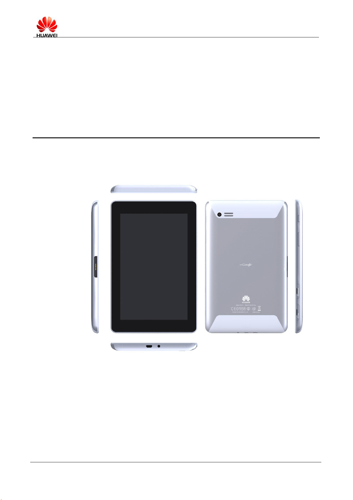
1.1 Appearance
1 Product Overview
1.2 Product Models
MediaPad 7 Lite has multiple models. The following table describes the main functional
differences of these models.

MediaPad 7 Lite Maintenance Manual
INTERNAL
2012-10-08
Huawei Confidential
Page 6 of 82
Model
Description
Difference
S7-931w
Wi-Fi Only
8G NAND FLASH
S7-931wA
Wi-Fi Only
4G NAND FLASH
S7-931wD
Wi-Fi Only
8G NAND FLASH with Dock
Dimensions (H × W × D)
11 mm x 194 mm × 120 mm
Weight
About 370 g (including the battery)
Screen
Type: IPS-LCD, Glare
Size: 7-inch
Resolution: WSVGA (1024 x 600 pixels)
Viewing angle: 80° (up)/80° (down)/80° (left)/80° (right)
Color: 16 million colors
Contrast: 800:1
Brightness: 350 cd/m2 (maximum)
LVDS interface
1.3 Product Features
7-inch capacitive multi-touch screen
Technologies for mobile network interfaces: GSM/GPRS/EDGE and UMTS/HSDPA
Multi-tab web page browser
High definition (HD) multimedia play
Android ICS 4.0
7-inch Wide Screen Video Graphics Array (WSVGA) In-Plane Switching (IPS)
(1024x600) HD multi-touch screen
Cortex A8 1.2GHz CPU
Rear network camera with 3.2 megapixels
Full HD play
GPS/A-GPS
4100 mAh battery
Wi-Fi 802.11b/g/n

MediaPad 7 Lite Maintenance Manual
INTERNAL
2012-10-08
Huawei Confidential
Page 7 of 82
Wi-Fi
Single band: 2.4 GHz 802.11 b/g/n; dual-band: 2.4 GHz/5GHz 802.11 a/b/g/n, WEP,
WPA, and WPA2
Working band: 2.4 GHz/5 GHz
Conducted power:
IEEE 802.11b: ≤ 18 dBm (*)
IEEE 802.11g: ≤ 16 dBm (*)
IEEE 802.11n: ≤ 14 dBm@MCS7 (*)
* The maximum power depends on the country code.
Conducted sensitivity:
IEEE 802.11b: –85 dBm@11 Mbit/s
IEEE 802.11g: –71 dBm@54 Mbit/s
IEEE 802.11n: –68 dBm@ MCS7
Bluetooth
Standard compliance: Bluetooth 3.0, 2.1 + EDR compatible
Transmit power: 6 dBm, Power Class 1.5
Litefile: A2DP, AVRCP, FTP, HSP, OPP, HID, PAN
Key and indicator
Power key
Volume adjustment key
Interface, sensor, and audio configuration
3.5 mm stereo headset interface
MicroSD card slot: compatible with the SDHC card, supporting the maximum memory
of 32 GB
USB interface: micro USB 2.0 MHL-compliant interface
SIM card slot
Built-in gravity sensor
Built-in actuator motor
Built-in loudspeaker and microphone
GPS
GPS/A-GPS
Processor
RK2918 ARM Cortex-A8 1.2GHz
Memory
RAM: 1 GB
Flash: 8 GB (standard), supporting 16 GB and 4 GB
MicroSD card: up to 32 GB

MediaPad 7 Lite Maintenance Manual
INTERNAL
2012-10-08
Huawei Confidential
Page 8 of 82
Network camera
Front network camera: CMOS, 300,000 pixels, fixed focal length, VGA
Rear network camera: CMOS, 3.2 megapixels, fixed focal length
Operating system
Linux 2.6.35
Android ICS 4.0
2 Maintenance Instructions
2.1 Applicable Scope
This document provides repair instructions for technicians at service centers authorized by
Huawei. Being Huawei proprietary, this document is accessible only for authorized service
centers and companies. Although every effort was made to ensure the accuracy of this

MediaPad 7 Lite Maintenance Manual
INTERNAL
2012-10-08
Huawei Confidential
Page 9 of 82
document, errors may still exist. If you find any errors or have any suggestions, please contact
Huawei's customer service.
2.2 Precautions
Maintenance and calibration operations are performed only by qualified technicians.
All maintenance and calibration operations are performed in antistatic rooms with
antistatic wrist straps correctly worn.
All components, screws, and insulators are correctly installed and all cables are correctly
connected after maintenance and calibration, and that all cables and wires are installed
and connected correctly.
Soldering is lead-free and compliant with the environmental protection requirements.
ESD is the main cause of damage to electrostatic-sensitive components. Each ASC must
exercise caution to avoid ESD damage and comply with the ESD protection requirements in
this manual.
2.3 Obtaining Product and Maintenance Information
To obtain product and maintenance information, visit Huawei website at:
http://www.huaweidevice.com/cn/technicaIndex.do.
MediaPad 7 Lite Maintenance Manual
INTERNAL
2012-10-08
Huawei Confidential
Page 10 of 82
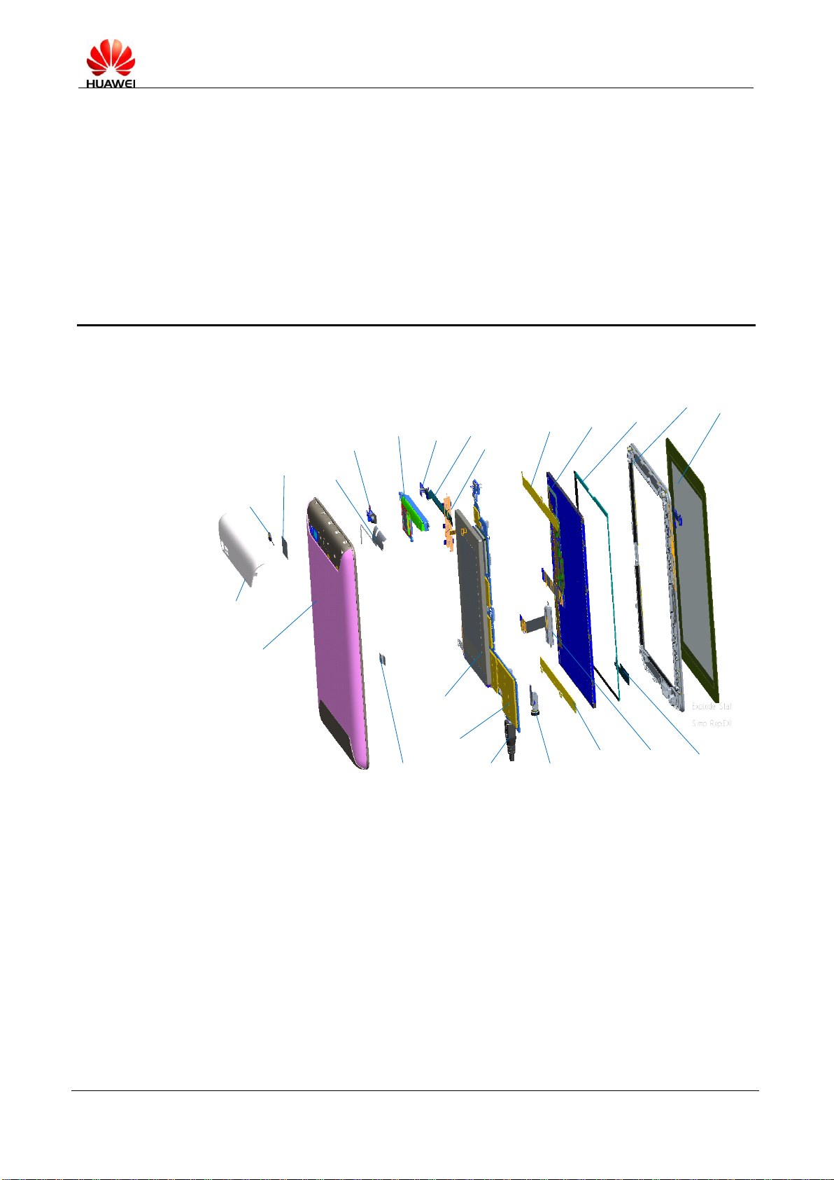
3 Explosive View Drawing
Mechanical exploded view
Decorating part
of the rear coverl
Protective glass of
the network camera
Mechanical label
Rear cover
assembly
Battery connector
tablet
Diversity
antenna
Front network
camera
Audio box
Side key
support
Battery
Main control
board
Headset socket
LCD tablet
LCD tablet
LCD tablet
POGOPIN
LCD
LCD foam
Antenna
Front cover
assembly
TP
Rear
network
camera
Antenna
USB
PCBA
MediaPad 7 Lite Maintenance Manual
INTERNAL
2012-10-08
Huawei Confidential
Page 11 of 82
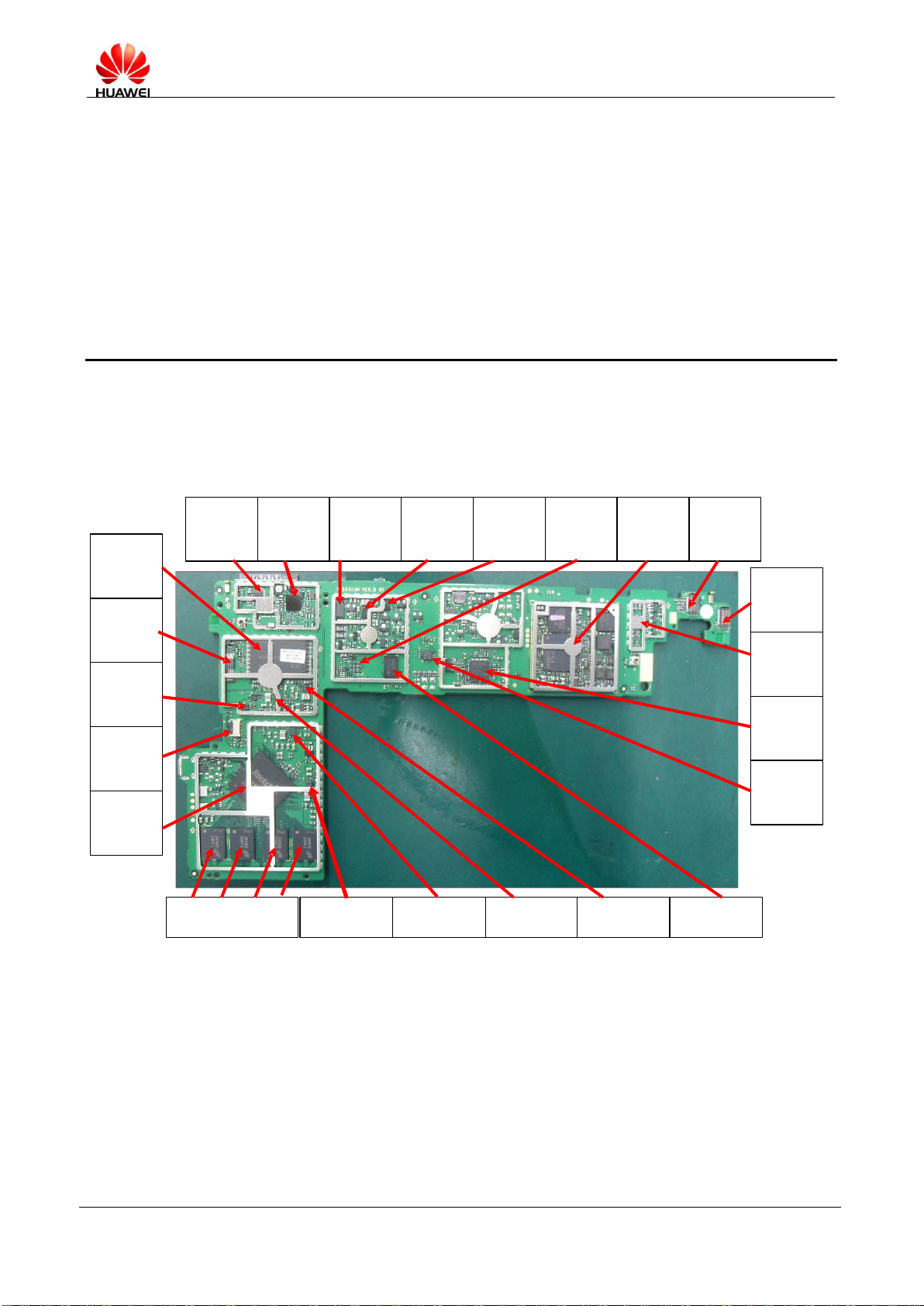
4 PCBA Components
U2101
Wi-Fi/BT driver
chip
U2301
GPS driver
chip
U1800
Coulometer
U1801
Charge IC
U1500
Level
conversion for
the microSD
card
U1401
RGB-to-MHL
driver chip
U2401
MU509
module
J1200
Connector of
the rear
network
camera
J1102
Connector of
the front
network
camera
U1700
Audio PA
U1600
Audio
decoding
U1900
Gravity
induction
U6001
IC for
switching
between a
27M clock and
a 32K clock
U 6000(RTC)
J1600
ZIF connector
of the headset
U1302
Nandflash
U4 CPU
U500 U5001,U5002,U5003
DDR3*4
U9001
Supplying power for
the DDR3, with 1.5
V output voltage
U9002
Supplying power for
the CPU, with 1.2 V
output voltage
U9000
Supplying power for
the IO, with 1.8 V
output voltage
U9003
Output voltage: 3 V
U1301
Converting RGB
into LVDS
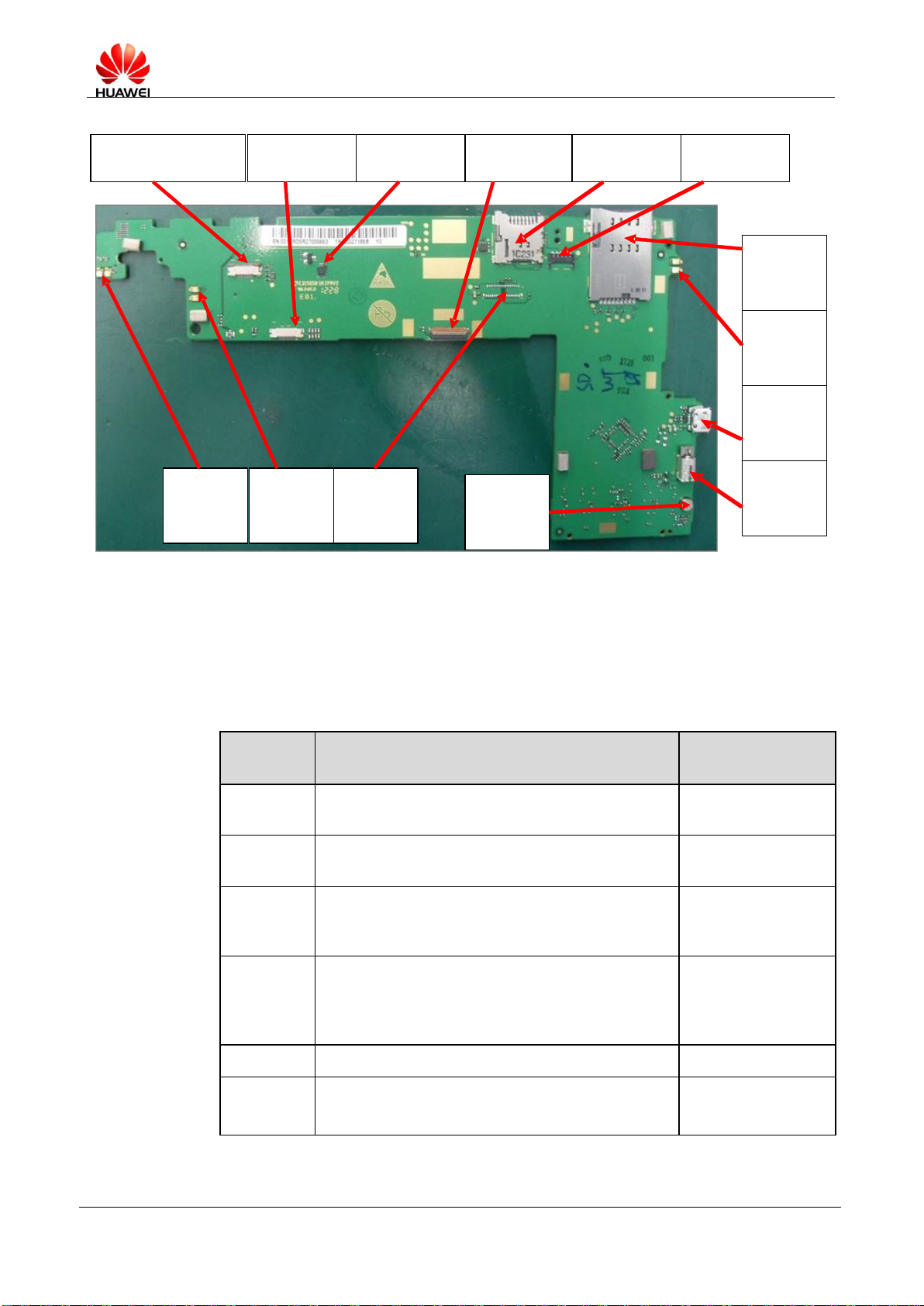
4.1 Components on the PCBA
MediaPad 7 Lite Maintenance Manual
INTERNAL
2012-10-08
Huawei Confidential
Page 12 of 82
J1701 and
J1700
Speaker
spring
J2500,J2501
3G antenna
spring
J1502
Connector of voltage and
volume keys
J1301
Touchscreen
connector
RESET IC
J1300
LCD connector
J1503
MicroSD card
holder
J1500
SIM card
holder
J2101/J2102
Wi-Fi/BT
antenna
spring
J1801
Battery
connector
J1802
USB
connector
U1703
Motor
MIC1700
Microphone
receiver
J1501 POP
PIN
connector
Part
Number
Description
Place
14240181
BTB Connector,Fmale,24Pin,0.4mm,SMT,Mating
Height 1.0mm,Terminal Dedicated
J1102, J1200
14090083
Soft Print Board
Connector,33Pin,0.3mm,0.3mm,0mm
J1300
14090042
Flexible Printed circuit Connector, 9 PIN, 0.5mm,
0.5mm, Angle,Single Row,PCB Welding
Type/SMT/Upside Contact,Mobile Dedicated
J1301, J1502
14240249
Card Connecter,MicroSD
Receptacle,8pin,PUSH-PUSH,1.1mm,Without
Lock,Without Hold Peg,1.45mm,Terminal
Dedicated
J1503
14240283
PC Connector,11,0.3mm,0.1mm,0.6mm
J1600
51621274
DKBA8.382.0615,Main Antenna SMT
Spring,C5600
J1700, J1701, J2101,
J2102, J2402, J2403
4.2 BOM List
(For your reference only. The latest BOM information can be downloaded in the system of
Huawei)

MediaPad 7 Lite Maintenance Manual
INTERNAL
2012-10-08
Huawei Confidential
Page 13 of 82
Part
Number
Description
Place
14240309
IO Connector,Female,5pin,WTB
Connector,SMT,Terminal Dedicated
J1801
14240272
IO Connector,Micro_B-Female,5pin,Side Plugging
Type,SMT,Terminal Dedicated
J1802
14240004
Coaxial Connector,RF
Switch,Straight,Female,SMT,Terminal Dedicated
J2100, J2400
14240433
RF Connector,Coaxial
Connector,50ohm,Straight,male,SMT,W.FL2,Termi
nal Dedicated
J2401
12070038
Temperature Compensated
Oscillator,26MHz,+/-1.5ppm(max),+1.8V,+/-0.5pp
m(max),-40degC,85degC,Terminal Dedicated
TCXO2300
39200455
Terminal Baseband process IC,Digital Base Band
Processor-1.2GHz-RK2918,1.2/1.8/2.6/2.5/3.3V,TF
BGA512,Terminal Dedicated
U4
39110682
LDO,2.5V,2%(Max),0.3A,SOT23-5,Terminal
dedicated
U1000
39110548
LDO,3.3V,2%,0.15A,SC70-5,Terminal Dedicated
U1001, U1300
39110490
Voltage Regulator,1.2V LDO
Regulator,2%,0.15A,SOT-23-5A,Terminal
Dedicated ,BT
U1002
39110471
Voltage
Regulator,2.85,3%,0.15A,SOT-23-5,Terminal
Dedicated (from39110307)
U1200
43140104
Interface Controller,RGB to LVDS,1.8/3.3V,
Terminal Dedicated
U1301
40060386
NAND Flash, 8GB(x8bit)
MLC,40MHz,8192KB,3.3V,TSOP48(Pb-Free),Medi
aPad 7 Lite Dedicate,Terminal Dedicated
U1302
36020411
CMOS,8BIT Level Shifter With Automatic
Direction Sensing,SDIO Bus
Application,WCSP20,7ns,50mA,CMOS,CMOS,25n
S,Terminal Dedicated,117C/W
U1500
36020401
CMOS,2BIT-1.8V/3.3V Level
Shifter ,GFN8(Pb-free),1.5ns,14mA,CMOS,Open
drain,Terminal Dedicated
U1501, U6002
43110077
AUDIO Chip,QFN,CODEC,Support I2S,PCM
Interface,ACE,Terminal Dedicated
U1600
MediaPad 7 Lite Maintenance Manual
INTERNAL
2012-10-08
Huawei Confidential
Page 14 of 82
Part
Number
Description
Place
39080127
Operation Amplifier,Audio Power
Amplifier,2.5V~5.5V,Differencial,Micro SMD
9pin(BGA Pb-Free),Terminal Dedicated
U1700
39110709
Power Driver,2A Boost DCDC,QFN10,Terminal
Dedicated
U1702
32050033
Vibrator,Cylindrical,3.0V,0.11A,11000rpm,9.5mm*
4.5mm*4.85mm,SMT, SANYO, 28.5ohm,Terminal
Dedicated
U1703
39070073
0.3~2.75V,Battery Gauge,SON,Terminal Dedicated
U1800
39070117
Battery Management IC, 4.2V,18V,Charger with
separate Power Path Control,WCSP,SMT,Terminal
Dedicated
U1801
38140064
Semiconductor
Sensor,Accelerometer,LGA,3axis,Terminal
Dedicated
U1900
39070145
Voltage Monitor,2.7V, Delay Reset
Chip,0.9V-6V,SOT23-3,Terminal Dedicated
U2000
47140049
RF Switch,0.5~3.0
GHz,SP3T,0.45dB,1.22,20dB,TSON,200~260V(HB
M),Terminal Dedicated
U2100
39210010
Terminal Baseband process IC,Single Band 2.4GHz
WLAN/Bluetooth 2.1/FM Single
chip-BCM4330,2.3~5.5V,WLBGA133(Pb-free)
U2101
39210036
Terminal Baseband Peripheral IC,GPS
Receiver,support
GLONESS,2.3~5.5V-WLBGA42(Pb-free),Terminal
Dedicated
U2300
47090053
RF LNA,1575MHz,14dB min.,1.6dB
max.,SOT886,Terminal Dedicated
U2301
36020366
CMOS,4BIT Level Shifter With Automatic
Direction
Sensing,WLCSP(Pb-free),7.4ns,50mA,CMOS,CMO
S,Terminal Dedicated
U2400
51078365
MU509-b,HSDPA/WCDMA 2100/900
EDGE/GPRS/GSM Four Band,China Hubei Open
Market,Module,Media Pad
U2401
40020189
DDR3 DRAM,2Gb
DDR3,1600MHz,8bit,1.5V,FBGA78,Terminal
Dedicated
U5000, U5001,
U5002, U5003
39130135
RTC,Real Time Clock,TSSOP8, Terminal Dedicated
U6000
MediaPad 7 Lite Maintenance Manual
INTERNAL
2012-10-08
Huawei Confidential
Page 15 of 82
Part
Number
Description
Place
38020033
Analog Switch,Single Channel
Bidirectional,1.65-5.5V,7~50ohm,250MHz,SC-70,S
C-88
U6001
36020336
LVCMOS,Unbuffer Single Inverter
Gate,SC-70,9.0ns,4.0mA,CMOS,CMOS
U6003
39110566
Switching Regulators,1~4V,1.5A,SMT,Terminal
Dedicated
U9000, U9001,
U9002, U9003
36020382
CMOS,Power on reset,MLP-8 2 x 2x
0.8mm-,0.5mm
Pitch,300ns,0.5mA,COMS,COMS,3ns
U9004
12020216
Crystal,37.4MHz,10pF/8.3pF/9pF,+/-10ppm,80ohm,
2016,Terminal Dedicated
X2100
12020125
Crystal,0.032768MHz,12.5pF+/-30ppm,60/80kohm,
3.2*1.5 SMD,Terminal Dedicate,ELOM,TS16949
X6000
12020171
Crystal Oscillator,27MHz,12pF,20 ppm,50ohm,3225
X6001
12020151
Crystal,24.000MHz,12pf,+/-v30ppm,50ohm,HCX-3
SB,Terminal Dedicated
X6002
MediaPad 7 Lite Maintenance Manual
INTERNAL
2012-10-08
Huawei Confidential
Page 16 of 82
5.1 Upgrade Environment
Item
Description
Remarks
Upgrade
environment
MicroSD card
> 512 MB
USB cable
Part Number: 97065432
Computer
Upgrade file
MediaPad 7 Lite
S7-931u
V100R001C001B010
This version is for your reference only.
Download the latest version for upgrade.
Update tool
RKBatchTool.exe
Upgrade
method
Using a microSD card
Using a USB cable
5 Software Upgrade
5.2 Upgrade Using a microSD Card
5.2.1 Copying the Upgrade File from the Computer
1. Check the current upgrade environment.
Ensure that the microSD card can be read and written.
2. Obtain the upgrade package.
Copy the dload directory to the microSD card.
3. Ensure that the battery charge level is sufficient or charge the battery during the upgrade
process.
MediaPad 7 Lite Maintenance Manual
INTERNAL
2012-10-08
Huawei Confidential
Page 17 of 82
5.3 Upgrade Process
1. Copy the dload directory to the root directory of the microSD card.
2. Check that the microSD card is not damaged.
If the upgrade package is large, remove and reinsert the microSD card, and then open the
package immediately after you copy the dload folder to the microSD card to ensure that
the microSD card is not damaged. If you directly open the upgrade packet in ZIP format
without removing and then reinserting the microSD card, you might only open the ZIP
package structure stored on the computer instead of the ZIP package on the microSD
card.
You can also use MyDiskTest to check the available storage space of the microSD card.
The size of the copied upgrade package must be smaller than this space.
3. Ensure that MediaPad 7 Lite is powered off.
4. Insert the microSD card into the MediaPad 7 Lite.
5. The microSD card is automatically upgraded after MediaPad 7 Lite is powered on.
Ensure that the available battery charge level exceeds 30%; otherwise, connect a USB
power supply.
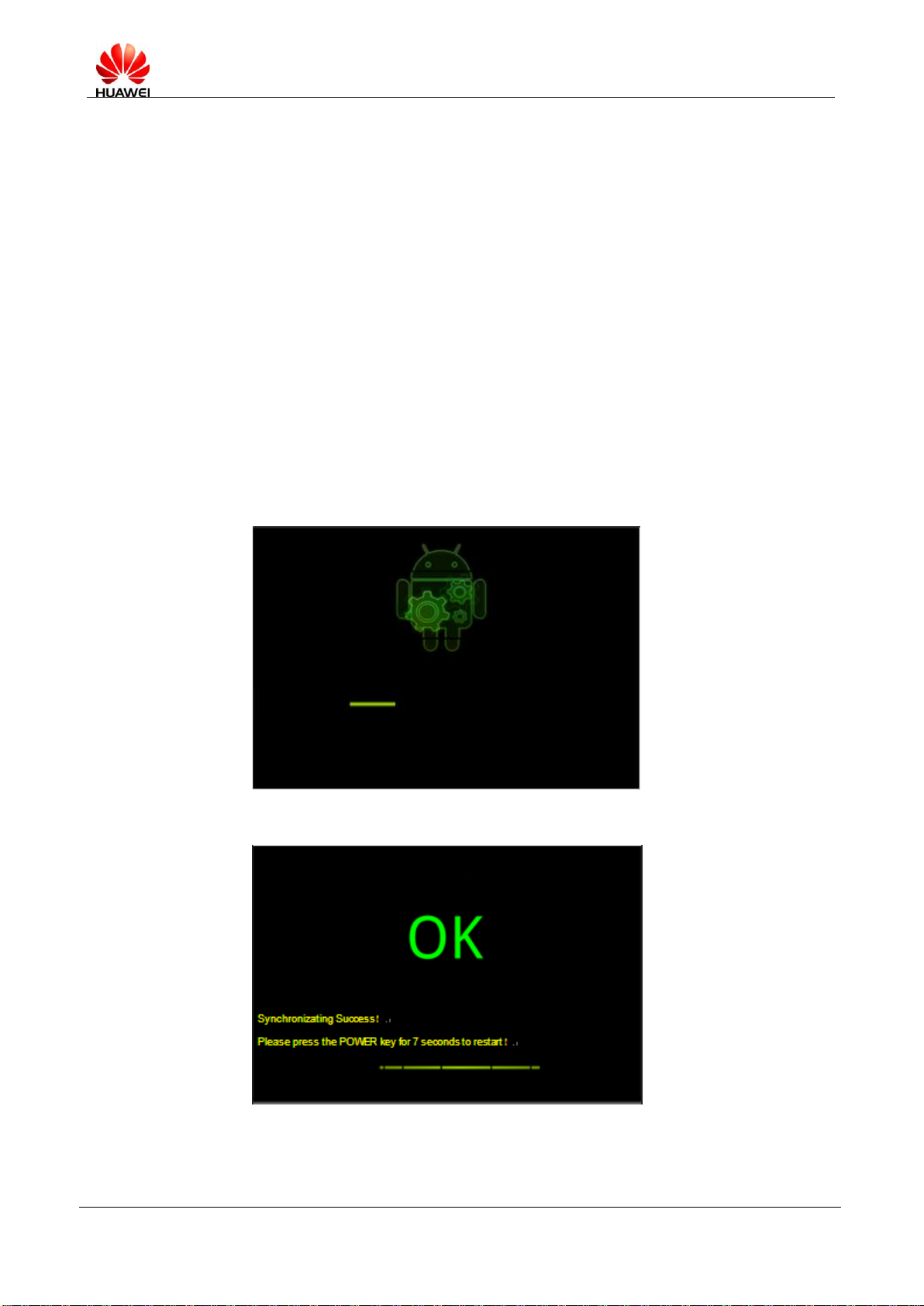
6. During the upgrade, the screen shown in the following figure is displayed.
7. When the upgrade succeeds, the screen shown in the following figure is displayed.
When the upgrade fails, the screen shown in the following figure is displayed.

MediaPad 7 Lite Maintenance Manual
INTERNAL
2012-10-08
Huawei Confidential
Page 18 of 82
8. After the upgrade, remove the microSD card. MediaPad 7 Lite automatically restarts.
5.4 Troubleshooting
Failure 1
A message is displayed on the screen during the upgrade, indicating that the upgrade
failed. In this case, check whether improper operations are performed. Then remove the
microSD card and install it again, or replace the microSD card and try upgrading the
software again.
Failure 2
If a failure occurs at the beginning of the upgrade process, check whether the upgrade
version is correct and whether MediaPad 7 Lite or microSD card is damaged.
MediaPad 7 Lite Maintenance Manual
INTERNAL
2012-10-08
Huawei Confidential
Page 19 of 82
6 Upgrading Using the USB
6.1 Entering USB Upgrade Mode
If MediaPad 7 Lite is connected to the computer for the first time, Found New Device is
displayed, indicating that the system has entered USB upgrade mode.
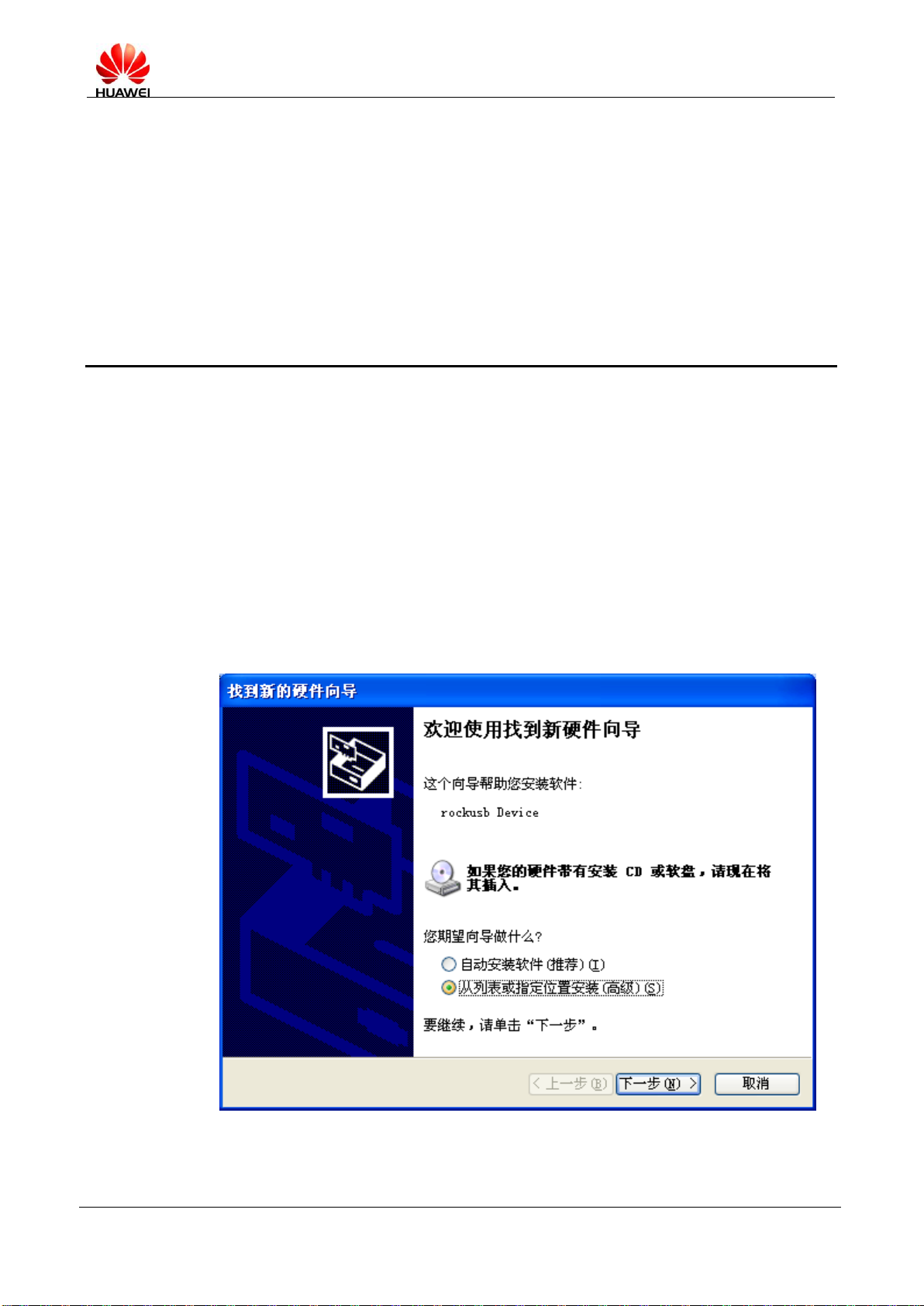
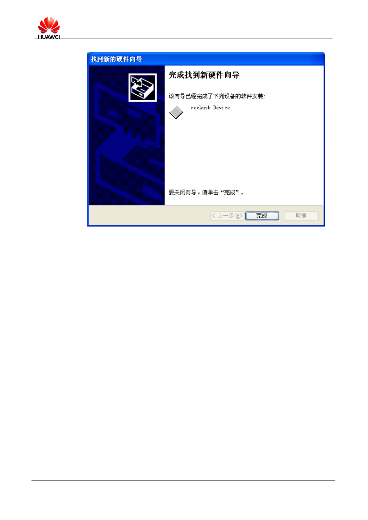
6.2 Installing the Driver
Before upgrading the firmware, close the player. Press the volume down key (-) and connect
MediaPad 7 Lite to the USB port of the PC. If you install the driver for the first time, the
window shown in the following figure is displayed.
Choose to install the driver from the list or the specified position and click Next.
MediaPad 7 Lite Maintenance Manual
INTERNAL
2012-10-08
Huawei Confidential
Page 20 of 82
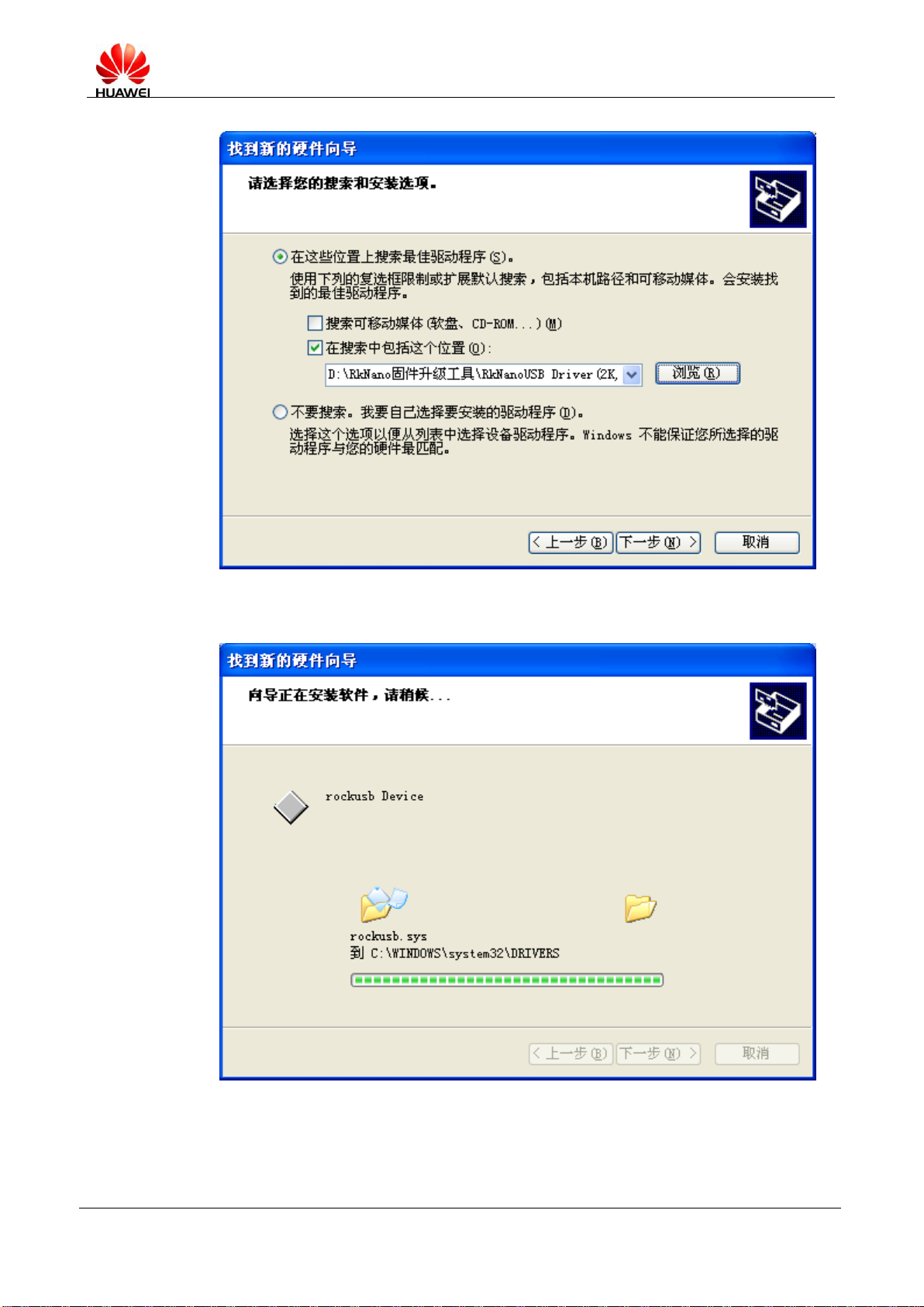
Select the rockusb.sys file under the driver folder.
MediaPad 7 Lite Maintenance Manual
INTERNAL
2012-10-08
Huawei Confidential
Page 21 of 82
Up to now, the driver of the USB device is installed.
MediaPad 7 Lite Maintenance Manual
INTERNAL
2012-10-08
Huawei Confidential
Page 22 of 82
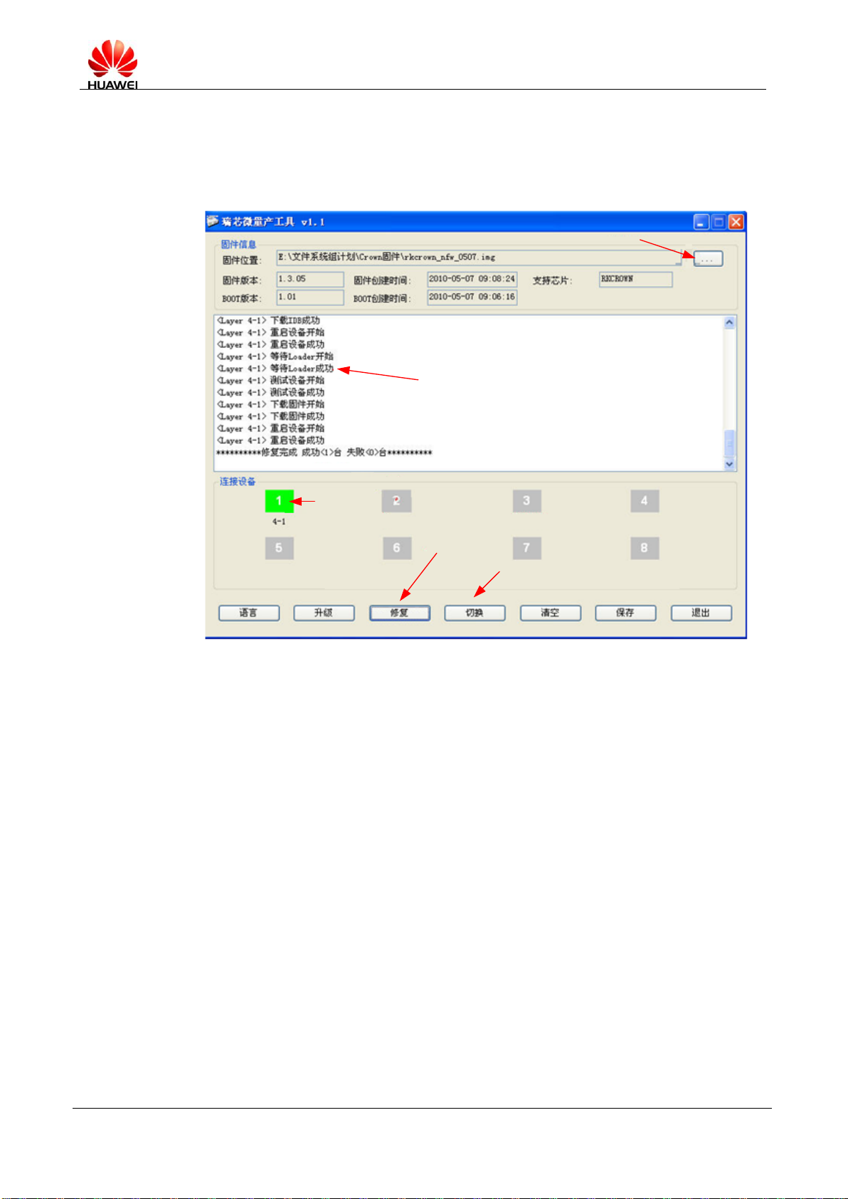
6.3 Batch Firmware Upgrade
Select the firmware.
Upgrade result
Device status:
Blue: The device is in the maskrom state.
Green: The device is in the loader state.
Pink: The device is in the MSC state.
Red: The operation failed.
Erase Flash memory and
then perform upgrade.
In the MSC state, perform switching
before upgrade or repair.
Main window
Procedure
1. Insert MediaPad 7 Lite and enable it to enter the upgrade mode (as shown in the
preceding main window).
2. Select firmware.
3. Ensure that MediaPad 7 Lite is in the Rockusb state (Maskrom or Loader state).
4. Upgrade or repair MediaPad 7 Lite.

MediaPad 7 Lite Maintenance Manual
INTERNAL
2012-10-08
Huawei Confidential
Page 23 of 82
Precautions
Perform batch upgrade on the hub. A maximum of four pieces of MediaPad 7 Lite can be
upgraded at the same time.
Restart the batch upgrade program after modifying the configuration file.
Do not start other upgrade programs when running RKBatchTool.exe.
MediaPad 7 Lite Maintenance Manual
INTERNAL
2012-10-08
Huawei Confidential
Page 24 of 82
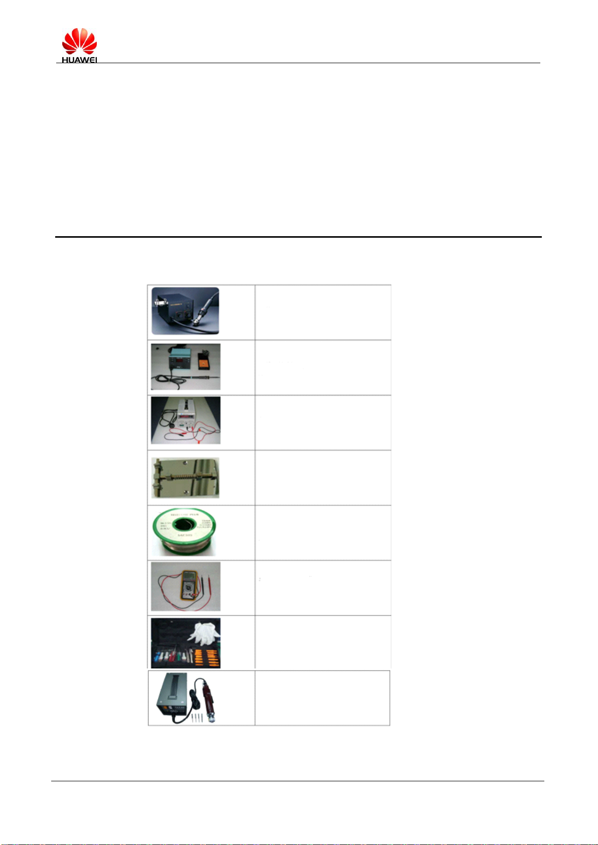
7 Maintenance Tools
Name: constanttemperature heat gun
Usage: to heat
components
Name: soldering iron
Usage: to maintain and
solder components
Name: DC power supply
Usage: to supply DC
current
Name: soldering table
Usage: to secure the
PCBA
Name: lead-free solder wire
Usage: for soldering
Name: digital multimeter
Usage: to measure during
repair
Name: toolkit
Usage: to assemble and
disassemble
components
Name: electric screwdriver
Usage: to fasten and
remove screws
MediaPad 7 Lite Maintenance Manual
INTERNAL
2012-10-08
Huawei Confidential
Page 25 of 82
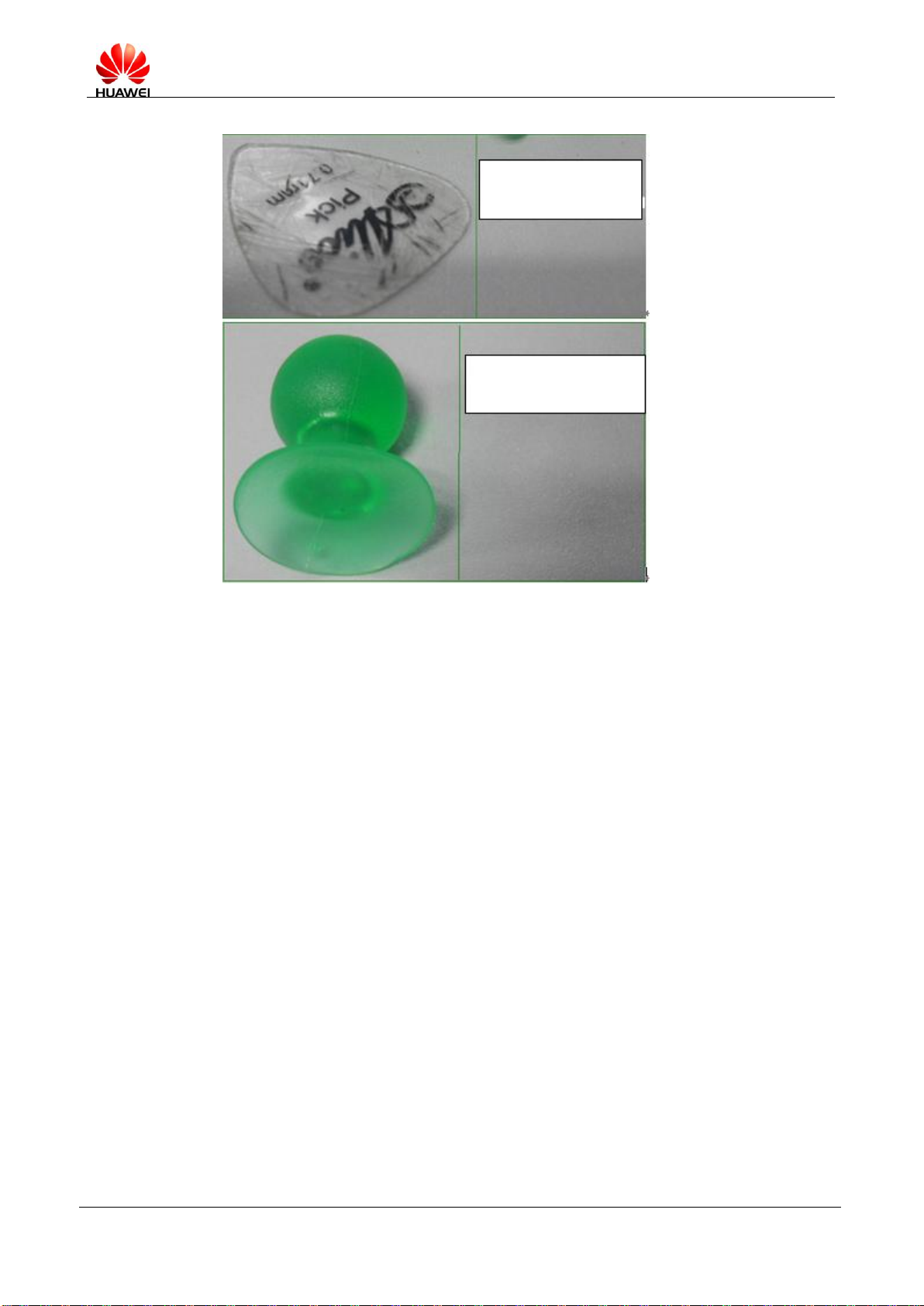
Name: guitar pick
Usage: to disassemble
MediaPad 7 Lite
Name: air suction ball
Usage: to disassemble
MediaPad 7 Lite
 Loading...