

Page 1

FusionServer Pro CH121 V5 Compute Node
V100R005
User Guide
Issue 06
Date 2019-08-10
HUAWEI TECHNOLOGIES CO., LTD.
Page 2

Copyright © Huawei Technologies Co., Ltd. 2019. All rights reserved.
No part of this document may be reproduced or transmitted in any form or by any means without prior written
consent of Huawei Technologies Co., Ltd.
Trademarks and Permissions
and other Huawei trademarks are trademarks of Huawei Technologies Co., Ltd.
All other trademarks and trade names mentioned in this document are the property of their respective
holders.
Notice
The purchased products, services and features are stipulated by the contract made between Huawei and the
customer. All or part of the products, services and features described in this document may not be within the
purchase scope or the usage scope. Unless otherwise specified in the contract, all statements, information,
and recommendations in this document are provided "AS IS" without warranties, guarantees or
representations of any kind, either express or implied.
The information in this document is subject to change without notice. Every effort has been made in the
preparation of this document to ensure accuracy of the contents, but all statements, information, and
recommendations in this document do not constitute a warranty of any kind, express or implied.
Huawei Technologies Co., Ltd.
Address: Huawei Industrial Base
Bantian, Longgang
Shenzhen 518129
People's Republic of China
Website: http://e.huawei.com
Issue 06 (2019-08-10) Copyright © Huawei Technologies Co., Ltd. i
Page 3

FusionServer Pro CH121 V5 Compute Node
User Guide
Purpose
This document describes the CH121 V5 compute node (CH121 V5) in terms of its
components, common operations, basic configuration, hardware installation, troubleshooting,
software and configuration utilities, electrostatic discharge (ESD) prevention, and product
specifications.
About This Document
About This Document
Intended Audience
This document is intended for:
l Enterprise administrators
l Enterprise end users
Symbol Conventions
The symbols that may be found in this document are defined as follows:
Symbol
Description
Indicates an imminently hazardous situation which, if not
avoided, will result in death or serious injury.
Indicates a potentially hazardous situation which, if not
avoided, could result in death or serious injury.
Indicates a potentially hazardous situation which, if not
avoided, may result in minor or moderate injury.
Indicates a potentially hazardous situation which, if not
avoided, could result in equipment damage, data loss,
performance deterioration, or unanticipated results.
NOTICE is used to address practices not related to personal
injury.
Issue 06 (2019-08-10) Copyright © Huawei Technologies Co., Ltd. ii
Page 4

FusionServer Pro CH121 V5 Compute Node
User Guide
Symbol Description
Change History
About This Document
Calls attention to important information, best practices and
tips.
NOTE is used to address information not related to personal
injury, equipment damage, and environment deterioration.
Issue
06 2019-08-10
05 2018-12-04
04 2018-10-22
03 2018-05-14
02 2017-12-28
01 2017-10-12
Date Description
l Added the support for Cascade Lake processors.
l Modified information about memory
compatibility.
l Modified technical specifications.
l Added procedure for installing an M.2 FRU.
l Added procedure for installing the supercapacitor.
l Added procedure for installing an NVMe drive.
l Added procedure for installing the BIOS battery.
l Added information about the Avago SAS3408 and
Avago SAS3004 iMR RAID controller cards.
l Modified the memory module installation
guidelines.
l This issue is the first official release.
Issue 06 (2019-08-10) Copyright © Huawei Technologies Co., Ltd. iii
Page 5

FusionServer Pro CH121 V5 Compute Node
User Guide Contents
Contents
About This Document.....................................................................................................................ii
1 Overview......................................................................................................................................... 1
1.1 Overview........................................................................................................................................................................ 1
1.2 Physical Structure........................................................................................................................................................... 3
1.3 Logical Structure ........................................................................................................................................................... 4
2 Hardware Description.................................................................................................................. 5
2.1 Front Panel......................................................................................................................................................................5
2.1.1 Appearance.................................................................................................................................................................. 5
2.1.2 Indicators and Buttons................................................................................................................................................. 6
2.1.3 Ports............................................................................................................................................................................. 8
2.1.4 Installation Positions....................................................................................................................................................8
2.2 Processor.........................................................................................................................................................................9
2.3 Memory........................................................................................................................................................................ 10
2.3.1 Memory Identifier......................................................................................................................................................10
2.3.2 Memory Subsystem Architecture.............................................................................................................................. 11
2.3.3 Memory Compatibility.............................................................................................................................................. 12
2.3.4 Memory Installation Guidelines................................................................................................................................ 15
2.3.5 Memory Installation Positions...................................................................................................................................15
2.3.6 Memory Protection Technologies.............................................................................................................................. 17
2.4 Storage.......................................................................................................................................................................... 17
2.4.1 Drive Configurations................................................................................................................................................. 17
2.4.2 Drive Numbering.......................................................................................................................................................17
2.4.3 Drive Indicators......................................................................................................................................................... 18
2.4.4 RAID Controller Card............................................................................................................................................... 20
2.5 Network........................................................................................................................................................................ 20
2.5.1 LOMs.........................................................................................................................................................................20
2.6 I/O Expansion............................................................................................................................................................... 21
2.6.1 PCIe Cards.................................................................................................................................................................21
2.6.2 PCIe Slot Description................................................................................................................................................ 22
2.7 Boards...........................................................................................................................................................................23
2.7.1 Mainboard..................................................................................................................................................................23
3 Basic Operations.......................................................................................................................... 25
Issue 06 (2019-08-10) Copyright © Huawei Technologies Co., Ltd. iv
Page 6

FusionServer Pro CH121 V5 Compute Node
User Guide Contents
3.1 Power-Off Procedure....................................................................................................................................................26
3.2 Power-On Procedure.....................................................................................................................................................27
3.3 Removing a CH121 V5................................................................................................................................................ 28
3.4 Installing a CH121 V5..................................................................................................................................................31
3.5 Removing the Cover.....................................................................................................................................................35
3.6 Installing the Cover...................................................................................................................................................... 35
3.7 Removing the Air Ducts............................................................................................................................................... 36
3.8 Installing the Air Duct.................................................................................................................................................. 37
3.9 Removing the PCIe Card Panel.................................................................................................................................... 39
3.10 Installing the PCIe Card Panel....................................................................................................................................40
3.11 Removing a PCIe Card............................................................................................................................................... 41
3.12 Installing a PCIe Card.................................................................................................................................................43
3.13 Removing a SAS/SATA Drive....................................................................................................................................46
3.14 Installing a SAS/SATA Drive.....................................................................................................................................47
3.15 Removing an NVMe Drive.........................................................................................................................................49
3.16 Installing an NVMe Drive ......................................................................................................................................... 62
4 Installation and Configuration................................................................................................. 71
4.1 Installation Environment Requirements....................................................................................................................... 71
4.1.1 Space and Airflow Requirements.............................................................................................................................. 71
4.1.2 Temperature and Humidity Requirements................................................................................................................. 71
4.1.3 Cabinet Requirements................................................................................................................................................72
4.2 Hardware Installation................................................................................................................................................... 72
4.2.1 Installation Overview................................................................................................................................................ 72
4.2.2 Unpacking the Compute Node.................................................................................................................................. 73
4.2.3 Installing Optional Parts............................................................................................................................................ 74
4.2.4 Installing the Compute Node.....................................................................................................................................75
4.2.5 Connecting to Network..............................................................................................................................................75
4.3 Initial Configuration..................................................................................................................................................... 75
4.3.1 Default Information................................................................................................................................................... 75
4.3.2 Configuration Overview............................................................................................................................................ 77
4.3.3 Changing Initial Passwords....................................................................................................................................... 78
4.3.3.1 Changing the Initial Password of the Default iBMC User..................................................................................... 78
4.3.4 Checking the Compute Node.....................................................................................................................................80
4.3.5 Setting the iBMC IP Address.................................................................................................................................... 82
4.3.6 Configuring RAID.....................................................................................................................................................83
4.3.7 Configuring the BIOS................................................................................................................................................83
4.3.7.1 Entering the BIOS.................................................................................................................................................. 84
4.3.7.1.1 Entering the BIOS (Skylake)...............................................................................................................................84
4.3.7.1.2 Entering the BIOS (Cascade Lake)..................................................................................................................... 86
4.3.7.2 Setting the System Boot Sequence......................................................................................................................... 88
4.3.7.3 Setting PXE for a NIC............................................................................................................................................ 89
4.3.7.4 Setting the BIOS Password.....................................................................................................................................90
Issue 06 (2019-08-10) Copyright © Huawei Technologies Co., Ltd. v
Page 7

FusionServer Pro CH121 V5 Compute Node
User Guide Contents
4.3.7.5 Selecting a Language..............................................................................................................................................90
4.3.7.6 Restarting the Compute Node.................................................................................................................................91
4.3.8 Installing an OS......................................................................................................................................................... 91
5 Optional Part Installation.......................................................................................................... 93
5.1 Precautions....................................................................................................................................................................93
5.2 Optional Parts............................................................................................................................................................... 93
5.2.1 Installing an M.2 FRU............................................................................................................................................... 93
5.2.2 Installing the Screw-in RAID Controller Card..........................................................................................................95
5.2.3 Installing the Avago SAS3004iMR PCIe RAID Control Card................................................................................. 97
5.2.4 Installing an M.2 FRU on the Avago SAS3004iMR PCIe RAID Controller Card................................................... 98
5.2.5 Installing the Supercapacitor..................................................................................................................................... 98
5.2.6 Installing a Mezzanine Card.................................................................................................................................... 101
5.2.7 Installing a Processor...............................................................................................................................................103
5.2.8 Installing a Memory Module................................................................................................................................... 110
5.2.9 Installing the TPM................................................................................................................................................... 113
6 Software and Hardware Compatibility.................................................................................115
7 Troubleshooting........................................................................................................................ 116
8 Software and Configuration Utilities....................................................................................117
8.1 Upgrading the System.................................................................................................................................................117
8.2 MM910....................................................................................................................................................................... 118
8.3 iBMC.......................................................................................................................................................................... 119
8.4 BIOS........................................................................................................................................................................... 120
8.5 FusionServer Tools uMate.......................................................................................................................................... 121
9 Safety Information.................................................................................................................... 123
9.1 Safety Instructions...................................................................................................................................................... 123
9.2 Maintenance and Warranty......................................................................................................................................... 126
10 ESD.............................................................................................................................................127
10.1 Preventing Electrostatic Discharge ..........................................................................................................................127
10.2 Grounding Methods to Prevent Electrostatic Discharge.......................................................................................... 127
11 Product Specifications............................................................................................................ 129
11.1 Technical Specifications........................................................................................................................................... 129
11.2 Environmental Specifications...................................................................................................................................132
11.3 Physical Specifications............................................................................................................................................. 133
12 Common Operations...............................................................................................................134
12.1 Querying the iBMC IP Address................................................................................................................................134
12.2 Logging In to the iBMC WebUI............................................................................................................................... 135
12.3 Logging In to the MM910 WebUI............................................................................................................................ 139
12.4 Collecting Log Information on the MM910 WebUI.................................................................................................144
12.5 Logging In to a Compute Node Using MM910 SOL...............................................................................................145
Issue 06 (2019-08-10) Copyright © Huawei Technologies Co., Ltd. vi
Page 8

FusionServer Pro CH121 V5 Compute Node
User Guide Contents
12.6 Managing the E9000 Server Using the Local KVM................................................................................................ 146
12.6.1 Logging In to the MM910 CLI..............................................................................................................................146
12.6.2 Logging In to the Operating System of a Compute Node..................................................................................... 147
12.6.3 Mounting the DVD Drive to a Compute Node......................................................................................................148
12.6.4 Logging In to a Compute Node or a Switch Module over SOL............................................................................149
12.7 Logging In to the Desktop of a Server..................................................................................................................... 151
12.7.1 Using the Remote Virtual Console........................................................................................................................151
12.7.1.1 iBMC.................................................................................................................................................................. 151
12.7.1.2 MM910............................................................................................................................................................... 154
12.7.2 Using the Independent Remote Console............................................................................................................... 155
12.7.2.1 Windows.............................................................................................................................................................155
12.7.2.2 Ubuntu................................................................................................................................................................ 157
12.7.2.3 macOS................................................................................................................................................................ 159
12.8 Logging In to the CLI...............................................................................................................................................161
12.8.1 Logging In to the CLI Using PuTTY over a Network Port...................................................................................161
12.9 VMD Management................................................................................................................................................... 163
12.9.1 Enabling VMD...................................................................................................................................................... 163
12.9.2 Disabling VMD..................................................................................................................................................... 164
12.10 Clearing Data from a Storage Device.....................................................................................................................164
A More Information..................................................................................................................... 167
A.1 Technical Support...................................................................................................................................................... 167
A.2 Product Information...................................................................................................................................................168
A.3 Product Configuration Resources.............................................................................................................................. 168
A.4 Maintenance Tools..................................................................................................................................................... 169
B Appendix.................................................................................................................................... 170
B.1 Product SN................................................................................................................................................................. 170
B.2 RAS Features............................................................................................................................................................. 171
Issue 06 (2019-08-10) Copyright © Huawei Technologies Co., Ltd. vii
Page 9

FusionServer Pro CH121 V5 Compute Node
User Guide
1.1 Overview
1.2 Physical Structure
1.3 Logical Structure
1 Overview
1 Overview
1.1 Overview
The CH121 V5 is a half-width compute node powered by Intel® Xeon® Scalable processors.
It delivers supreme computing power, large memory capacity, and outstanding scalability.
The CH121 V5 provides dense computing capability and an ultra-large memory. It is
optimized for virtualization, cloud computing, high-performance computing, and computeintensive enterprise applications.
The CH121 V5 compute nodes are installed in an E9000 chassis and are centrally managed by
the management module.
Issue 06 (2019-08-10) Copyright © Huawei Technologies Co., Ltd. 1
Page 10

FusionServer Pro CH121 V5 Compute Node
User Guide
Figure 1-1 CH121 V5
1 Overview
Issue 06 (2019-08-10) Copyright © Huawei Technologies Co., Ltd. 2
Page 11

FusionServer Pro CH121 V5 Compute Node
User Guide
1.2 Physical Structure
Figure 1-2 CH121 V5 physical structure
1 Overview
1 (Optional) HHHL PCIe riser
2 (Optional) HHHL PCIe card
module
3 (Optional) M.2 SSDs 4 (Optional) USB flash drive
5 (Optional) TPM 6 Screw-in RAID controller
card
7 (Optional) Supercapacitor 8 Heat sinks
9 Mainboard 10
11
Drives
a
12
(Optional) M.2 FRUs
(Optional) M.2 adapter
b
b
13 Drive cage 14 Processors
15 Mezzanine card 16 BIOS battery
17 Memory modules - -
Issue 06 (2019-08-10) Copyright © Huawei Technologies Co., Ltd. 3
Page 12

FusionServer Pro CH121 V5 Compute Node
User Guide
l a: The drive slots support 2.5-inch SAS/SATA/NVMe drives and M.2 modules and
mixed configuration of them.
l b: An M.2 module is a 2.5-inch drive module that consists of one M.2 adapter and two
M.2 FRUs.
1.3 Logical Structure
Figure 1-3 CH121 V5 logical structure
1 Overview
l The server supports one or two Intel® Xeon® Scalable processors.
l The server supports up to 24 memory modules.
l The CPUs (processors) interconnect with each other through two UPI links at a speed of
up to 10.4 GT/s.
l The mezzanine cards connect to the processors through PCIe buses to provide service
ports.
l The Platform Controller Hub (PCH) has a built-in MAC chip and provides two 10 Gbit/s
ports.
l The storage module, consisting of a RAID controller card and a drive backplane,
connects to the CPUs through PCIe buses.
l The BMC provides device management functions, such as compute node power control,
slot number acquisition, PSU detection, and KVM over IP.
Issue 06 (2019-08-10) Copyright © Huawei Technologies Co., Ltd. 4
Page 13

FusionServer Pro CH121 V5 Compute Node
User Guide
2.1 Front Panel
2.2 Processor
2.3 Memory
2 Hardware Description
2 Hardware Description
2.4 Storage
2.5 Network
2.6 I/O Expansion
2.7 Boards
2.1 Front Panel
2.1.1 Appearance
Figure 2-1 Front view (with an M.2 module)
Issue 06 (2019-08-10) Copyright © Huawei Technologies Co., Ltd. 5
Page 14

FusionServer Pro CH121 V5 Compute Node
User Guide
2 Hardware Description
1 Slide-out label plate (with an
SN label)
3 Ejector release button 4 Ejector lever
5
7 M.2 FRU 8 M.2 adapter
9
l a: The drive slots support 2.5-inch SAS/SATA/NVMe drives and M.2 modules and
mixed configuration of them.
l b: An M.2 module is a 2.5-inch drive module that consists of one M.2 adapter and two
M.2 FRUs.
2.5" drive
M.2 module
a
2.1.2 Indicators and Buttons
Positions
Figure 2-2 Indicators and buttons on the front panel
2 PCIe panel
6 Model
b
- -
1
3 Health status indicator - -
Issue 06 (2019-08-10) Copyright © Huawei Technologies Co., Ltd. 6
Power button/indicator 2 UID button/indicator
Page 15

FusionServer Pro CH121 V5 Compute Node
User Guide
Description
Table 2-1 Indicators and buttons on the front panel
2 Hardware Description
Silkscreen Indicator/
Button
Power button/
indicator
UID UID button/
indicator
Description
Power indicator:
l Off: The device is not powered on.
l Steady yellow: The device is powered on.
l Blinking yellow: The power button is locked. The
power button is locked when the iBMC is starting.
l Steady green: The device is ready to power on.
Power button:
l When the device is powered on, you can press this
button to gracefully shut down the OS.
l When the device is powered on, holding down this
button for 6 seconds will forcibly power off the
device.
l When the power indicator is steady green, you can
press this button to power on the device.
The UID button/indicator helps identify and locate a
device.
UID indicator:
l Off: The device is not being located.
l Blinking blue: The device has been located and is
differentiated from other devices that have also
been located.
l Steady blue: The device is being located.
UID button:
l You can turn on or off the UID indicator by
pressing the UID button or by using the iBMC or
MM910 CLI or WebUI.
l You can press this button to turn on or off the UID
indicator.
l You can press and hold down this button for 4 to 6
seconds to reset the iBMC.
HLY Health status
indicator
Issue 06 (2019-08-10) Copyright © Huawei Technologies Co., Ltd. 7
l Off: The device is powered off or is faulty.
l Blinking red at 1 Hz: A major alarm has been
generated for the device.
l Blinking red at 5 Hz: A critical alarm has been
generated for the device, or the device is not
securely installed.
l Steady green: The device is operating properly.
Page 16

FusionServer Pro CH121 V5 Compute Node
User Guide
2.1.3 Ports
Port Positions
Figure 2-3 Ports on the front panel
2 Hardware Description
1 USB 3.0 ports 2 -
Port Description
Port
USB port USB 3.0 2 Used to connect to a USB device.
Type Quantity Description
2.1.4 Installation Positions
The CH121 V5 is installed in a half-width slot in the front of the E9000 chassis. An E9000
chassis can house a maximum of 16 CH121 V5 compute nodes.
NOTICE
Before connecting an external USB
device, check that the USB device
functions properly. The server may
operate abnormally if an abnormal
USB device is connected.
Issue 06 (2019-08-10) Copyright © Huawei Technologies Co., Ltd. 8
Page 17

FusionServer Pro CH121 V5 Compute Node
User Guide
Figure 2-4 Installation positions
2 Hardware Description
2.2 Processor
l The server supports one or two processors.
l If only one processor is required, install it in socket CPU1.
l The same model of processors must be used in a server.
l Contact your local Huawei sales representative or use the Intelligent Computing
Compatibility Checker to determine the components to be used.
Issue 06 (2019-08-10) Copyright © Huawei Technologies Co., Ltd. 9
Page 18

FusionServer Pro CH121 V5 Compute Node
User Guide
Figure 2-5 Processor positions
2 Hardware Description
2.3 Memory
2.3.1 Memory Identifier
You can determine the memory module properties based on the label attached to the memory
module.
Figure 2-6 Memory identifier
Issue 06 (2019-08-10) Copyright © Huawei Technologies Co., Ltd. 10
Page 19

FusionServer Pro CH121 V5 Compute Node
User Guide
callout Description Definition
2 Hardware Description
1 Capacity of the memory module.
2 Number of ranks of the memory
module.
3 Data width on the DRAM.
4 Type of the memory interface.
5 Maximum memory speed.
l 8 GB
l 16 GB
l 32 GB
l 64 GB
l 128 GB
l 1R: single-rank
l 2R: dual-rank
l 4R: quad-rank
l 8R: octal-rank
l X4: 4-bit
l X8: 8-bit
l PC3: DDR3
l PC4: DDR4
l 2133 MT/S
l 2400 MT/S
l 2666 MT/S
l 2933 MT/S
6 Column Access Strobe (CAS)
latency.
7 DIMM type.
2.3.2 Memory Subsystem Architecture
The CH121 V5 provides 24 memory slots. Each processor integrates six memory channels.
Install the memory modules in the primary memory channels first. If the primary memory
channel is not populated, the memory modules in secondary memory channels cannot be used.
Table 2-2 Memory channels
CPU
CPU 1 1A (primary) DIMM000(1A1)
Memory Channel Memory Slot
1A DIMM001(1A2)
1B (primary) DIMM010(1B1)
l P: 15
l T: 17
l R: RDIMM
l L: LRDIMM
1B DIMM011(1B2)
Issue 06 (2019-08-10) Copyright © Huawei Technologies Co., Ltd. 11
Page 20

FusionServer Pro CH121 V5 Compute Node
User Guide
CPU Memory Channel Memory Slot
CPU 2 2A (primary) DIMM100(2A1)
2 Hardware Description
1C (primary) DIMM020(1C1)
1C DIMM021(1C2)
1D (primary) DIMM030(1D1)
1D DIMM031(1D2)
1E (primary) DIMM040(1E1)
1E DIMM041(1E2)
1F (primary) DIMM050(1F1)
1F DIMM051(1F2)
2A DIMM101(2A2)
2B (primary) DIMM110(2B1)
2.3.3 Memory Compatibility
Observe the following rules when configuring DDR4 memory modules:
2B DIMM111(2B2)
2C (primary) DIMM120(2C1)
2C DIMM121(2C2)
2D (primary) DIMM130(2D1)
2D DIMM131(2D2)
2E (primary) DIMM140(2E1)
2E DIMM141(2E2)
2F (primary) DIMM150(2F1)
2F DIMM151(2F2)
Issue 06 (2019-08-10) Copyright © Huawei Technologies Co., Ltd. 12
Page 21

FusionServer Pro CH121 V5 Compute Node
User Guide
l A server must use the same model of DDR4 memory modules, and all the memory
modules operate at the same speed, which is the smallest value of:
l Memory speed supported by a processor
l Maximum operating speed of a memory module
l The DDR4 memory modules of different types (RDIMM and LRDIMM) cannot be used
together.
l Contact your local Huawei sales representative or use the Intelligent Computing
Compatibility Checker to determine the components to be used.
l The memory can be used with Intel® Xeon® Scalable Skylake and Cascade Lake
processors. The maximum memory capacity supported varies depending on the
processor model.
– Skylake processors
n M processors: 1.5 TB/socket
n Other processors: 768 GB/socket
2 Hardware Description
– Cascade Lake processors
n L processors: 4.5 TB/socket
n M processors: 2 TB/socket
n Other processors: 1 TB/socket
l The total memory capacity is the sum of the capacity of all DDR4 memory modules.
The total memory capacity cannot exceed the maximum memory capacity supported by
the CPUs.
l Use the Intelligent Computing Compatibility Checker to determine the capacity type
of a single memory module.
l The maximum number of memory modules supported by a server varies depending on
the CPU type, memory type, rank quantity, and operating voltage.
NOTE
Each memory channel supports a maximum of 8 ranks. The number of memory modules
supported by each channel varies depending on the number of ranks supported by each channel:
Number of memory modules supported by each channel ≤ Number of ranks supported by each
memory channel/Number of ranks supported by each memory module
l A memory channel supports more than eight ranks for LRDIMMs.
NOTE
A quad-rank LRDIMM generates the same electrical load as a single-rank RDIMM on a memory
bus.
l DDR4 memory modules of different specifications (capacity, bit width, rank, and height)
can be used together for capacity expansion purposes. However, the memory Reliability,
Availability, and Serviceability (RAS) features may be affected.
Issue 06 (2019-08-10) Copyright © Huawei Technologies Co., Ltd. 13
Page 22

FusionServer Pro CH121 V5 Compute Node
User Guide
Observe the following rules when you need to use different types of memory modules in
a compute node:
– RDIMMs and LRDIMMs cannot be used together.
– Do not use 128 GB memory modules together with memory modules of other
capacities.
– If memory modules with different rank quantities need to be installed in the same
channel, install the memory modules with more ranks in slots farther away from the
CPU.
For example, install the dual-rank memory module in slot 1A1 and the single-rank
memory module in slot 1A2.
– Memory modules of different speeds can be mixed in any way. However, the
memory speed is the lowest speed of the memory modules configured.
– RAS features, such as memory mirroring, single device data correction (SDDC),
SDDC+1, and double device data correction (DDDC), are not supported if x4 and
x8 memory modules are used together.
Table 2-3 DDR4 memory specifications
2 Hardware Description
Parameter
Specifications
Rank Single rank Dual rank Quad rank Octal rank
Rated speed (MT/s)
2933
a
2933
a
2666 2666
Operating voltage (V) 1.2 1.2 1.2 1.2
Maximum number of DDR4
memory modules in a node
Maximum capacity per
24 24 24
b
16 32 64 128
24
c
DDR4 memory module
(GB)
Maximum DDR4 memory
384 768 1536
3072
c
capacity of the node (GB)
Maximum
operating
speed
(MT/s)
One DDR4
memory
module per
channel
Two DDR4
a
2933
2666 2666 2666 2666
2933
a
2666 2666
memory
modules per
channel
Issue 06 (2019-08-10) Copyright © Huawei Technologies Co., Ltd. 14
Page 23

FusionServer Pro CH121 V5 Compute Node
User Guide
Parameter Specifications
l a: If the Cascade Lake processor is used, the rated speed and maximum operating speed
of the RDIMM can reach 2933 MT/s. If the Skylake processor is used, the rated speed
and maximum operating speed of a DDR4 memory module can reach 2666 MT/s only.
l b: The maximum number of DDR4 memory modules is based on dual-processor
configuration. The value is halved for a server with only one processor.
l c: The maximum DDR4 memory capacity varies depending on the processor type. The
value listed in this table is based on the assumption that twenty-four 128 GB DDR4
memory modules are configured.
2.3.4 Memory Installation Guidelines
l Observe the following when configuring DDR4 memory modules:
– Install memory modules only when corresponding processors are installed.
– Do not install LRDIMMs and RDIMMs in the same server.
– Install filler memory modules in vacant slots.
l Observe the following when configuring DDR4 memory modules in specific operating
mode:
– Memory sparing mode
n Comply with the general installation guidelines.
n Each memory channel must have a valid online spare configuration.
n The channels can have different online spare configurations.
n Each populated channel must have a spare rank.
– Memory mirroring mode
n Comply with the general installation guidelines.
n Install memory modules for channels 1 and 2 or channels 3 and 4. The
memory modules installed must be identical in size and organization.
n For a multi-processor configuration, each processor must have a valid memory
mirroring configuration.
– Memory scrubbing mode
n Comply with the general installation guidelines.
2 Hardware Description
2.3.5 Memory Installation Positions
A CH121 V5 supports a maximum of 24 DDR4 memory modules. Balanced memory
configuration is recommended for optimal memory performance.
Issue 06 (2019-08-10) Copyright © Huawei Technologies Co., Ltd. 15
Page 24

FusionServer Pro CH121 V5 Compute Node
User Guide
Figure 2-7 Memory slots
Figure 2-8 DDR4 memory installation guidelines (1 processor)
2 Hardware Description
Figure 2-9 DDR4 memory installation guidelines (2 processors)
Issue 06 (2019-08-10) Copyright © Huawei Technologies Co., Ltd. 16
Page 25

FusionServer Pro CH121 V5 Compute Node
User Guide
2.3.6 Memory Protection Technologies
The following memory protection technologies are supported:
l ECC
l Full mirroring
l Address range mirroring
l Rank sparing mode
l Faulty DIMM isolation
l Memory thermal throttling
l Memory address parity protection
l Adaptive double device data correction (ADDDC)
l Memory demand/patrol scrubbing
l Data scrambling
l ADDDC+1
2 Hardware Description
2.4 Storage
2.4.1 Drive Configurations
Table 2-4 Drive configurations
Configuration
Front drives
l a: Only 2.5-inch drives fit into the front slots.
l b: Mixed configuration of M.2 modules and SAS/SATA/NVMe drives is supported.
l Contact your local Huawei sales representative or use the Intelligent Computing
Compatibility Checker to determine the components to be used.
a
Maximum Drives Drive Management
Mode
b
2
l Slots 0 and 2 support
SAS/SATA/NVMe
drives.
l M.2 FRUs can be
installed only in slots 0
to 3.
1 x RAID controller card
2.4.2 Drive Numbering
l SAS/SATA/NVMe drives
Issue 06 (2019-08-10) Copyright © Huawei Technologies Co., Ltd. 17
Page 26

FusionServer Pro CH121 V5 Compute Node
User Guide
Figure 2-10 Drive numbering
l M.2 FRU
Figure 2-11 Drive numbering
2 Hardware Description
2.4.3 Drive Indicators
SAS/SATA Drive Indicators
Figure 2-12 SAS/SATA drive indicators
Table 2-5 Description of SAS/SATA drive indicators
Green Indicator
Steady on Off The drive is in position.
Blinking at 4 Hz Off Data is being read or written normally, or
Steady on Blinking at 1 Hz The drive is being located.
Blinking at 1 Hz Blinking at 1 Hz The data on the secondary drive is being
Yellow Indicator Description
data on the primary drive is being rebuilt.
rebuilt.
Off Steady on A member drive in the RAID array is
removed.
Steady on Steady on The drive is faulty.
Issue 06 (2019-08-10) Copyright © Huawei Technologies Co., Ltd. 18
Page 27

FusionServer Pro CH121 V5 Compute Node
User Guide
M.2 FRU Indicators
Figure 2-13 M.2 FRU indicators
Table 2-6 M.2 FRU indicator description
2 Hardware Description
Indicator
M.2 FRU fault indicator
M.2 FRU activity
indicator
NVMe SSD Indicators
Figure 2-14 NVMe SSD indicators
Description
l Off: The M.2 FRU is running properly.
l Blinking yellow: The M.2 FRU is being located, or RAID
is being rebuilt.
l Steady yellow: The M.2 FRU is faulty or not detected.
l Off: The M.2 FRU is not in position or is faulty.
l Blinking green: Data is being read, written, or
synchronized.
l Steady green: The M.2 FRU is inactive.
l If the VMD function is enabled and the latest Intel RSTe driver is installed, NVMe SSDs
support surprise hot swap.
Table 2-7 NVMe SSD indicators (VMD enabled)
Green Indicator
Off Off The NVMe SSD cannot be detected.
Steady green Off The NVMe SSD is working properly.
Blinking green at 2HzOff Data is being read from or written to the
Off Blinking yellow at
Issue 06 (2019-08-10) Copyright © Huawei Technologies Co., Ltd. 19
Yellow Indicator Description
NVMe SSD.
The NVMe SSD is being located.
2 Hz
Page 28

FusionServer Pro CH121 V5 Compute Node
User Guide
Green Indicator Yellow Indicator Description
2 Hardware Description
Off Blinking yellow at
8 Hz
Steady green/Off Steady yellow The NVMe SSD is faulty.
l If the VMD function is disabled, NVMe SSDs support only orderly hot swap.
Table 2-8 NVMe SSD indicators (VMD disabled)
Green Indicator
Off Off The NVMe SSD cannot be detected.
Steady green Off The NVMe SSD is working properly.
Blinking green at 2HzOff Data is being read from or written to the
Off Blinking yellow at
Off Blinking yellow at
Steady green/Off Steady yellow The NVMe SSD is faulty.
Yellow Indicator Description
2 Hz
0.5 Hz
The data on the secondary NVMe drive is
being rebuilt.
NVMe SSD.
The NVMe SSD is being located or hotswapped.
The hot removal process is complete, and
the NVMe SSD is removable.
2.4.4 RAID Controller Card
The RAID controller card supports RAID configuration, RAID level migration, and drive
roaming.
l Contact your local Huawei sales representative or use the Intelligent Computing
Compatibility Checker to determine the components to be used.
Table 2-9 RAID levels supported by the CH121 V5
RAID
Level
RAID 0 Low High High 2 100%
RAID 1 High Low Low 2 50%
Reliability Read
2.5 Network
Performan
ce
Write
Performan
ce
Minimum
Number of
Drives
Drive
Utilization
2.5.1 LOMs
The LOM is a network interface module (X722) integrated in the PCH. It can be connected to
an I/O module (switch module). The LOM provides two 10GE network ports for connecting
Issue 06 (2019-08-10) Copyright © Huawei Technologies Co., Ltd. 20
Page 29

FusionServer Pro CH121 V5 Compute Node
User Guide
to the Base network ports of the switch modules in slots 2X and 3X. The LOM supports Wake
on LAN (WOL) and PXE functions.
Figure 2-15 Connections between the LOM and I/O modules
2 Hardware Description
NOTE
l In addition to the LOM, the compute node connects to the Fabric ports of the switch modules
through the network ports on mezzanine cards.
l Powering off the compute node forcibly will make the WOL function of the LOM ports invalid.
l If flow control is enabled for a LOM port, the switch module connected to the LOM port must also
have flow control enabled.
Table 2-10 I/O modules supported by the LOM
I/O Module
CX916 2X/3X √ -
CX920 2X/3X √ -
I/O Module
Slot
1E/4E × The LOM cannot communicate
1E/4E × The LOM cannot communicate
LOM Remarks
with the I/O modules in slots 1E
and 4E.
with the I/O modules in slots 1E
and 4E.
2.6 I/O Expansion
2.6.1 PCIe Cards
l The server supports a range of PCIe cards to provide diverse expandability and ease of
peripheral connections.
Issue 06 (2019-08-10) Copyright © Huawei Technologies Co., Ltd. 21
Page 30

FusionServer Pro CH121 V5 Compute Node
User Guide
l Contact your local Huawei sales representative or use the Intelligent Computing
Compatibility Checker to determine the components to be used.
2.6.2 PCIe Slot Description
NOTE
The PCIe slots mapping to a vacant CPU socket are unavailable.
Table 2-11 PCIe slot description
2 Hardware Description
PCIe
Slot
RAID
control
Displ
ay on
BMC
\ CPU 1 PCIe
CPU PCIe
Stand
ards
3.0
ler
card
LOM \ CPU 1 PCIe
3.0
Mezz1 \ CPU 1 PCIe
3.0
Conne
ctor
Width
Bus
Width
Port
No.
Ro
ot
Por
t
(B/
D/
F)
x8 x8 Port1A 17:
00.
00
x8 x8 Port1C 17:
02.
00
x16 or
two x8
x16 or
two x8
Port2A
or
(Port2
A+Port
2C)
3a:
00.
0
3a:
02.
0
De
vic
e
(B/
D/F
)
18:0
0.00
1c:
00.0
0
3b:
00.0
3c:
00.0
Slot
Size
-
-
-
Mezz2 \ CPU 2 PCIe
3.0
PCIe
Riser1
PCIe
riser
CPU 1 PCIe
3.0
card 1
NVMe
SSD0
disk 0 CPU 2 PCIe
3.0
x16 or
two x8
x16 or
two x8
Port2A
or
(Port
2A
+Port2
C)
ae:
00.
0
ae:
02.
0
x16 x16 Port3A 5d:
00.
0
x4 x4 Port1C 85:
02.
af:
00.0
b0:0
0.0
5e:
00.0
86:0
0.0
-
HHHL
2.5"
drive
00
NVMe
SSD2
disk 2 CPU 2 PCIe
3.0
x4 x4 Port1D 85:
03.
87:0
0.0
2.5"
drive
00
Issue 06 (2019-08-10) Copyright © Huawei Technologies Co., Ltd. 22
Page 31
FusionServer Pro CH121 V5 Compute Node
User Guide
2 Hardware Description
PCIe
Slot
l The B/D/F (Bus/Device/Function Number) is the default value when the server is fully
configured with PCIe devices. The value may differ if the server is not fully configured
with PCIe devices or if a PCIe card with a PCI bridge is configured.
l Root Port (B/D/F) indicates the B/D/F of an internal PCIe root port of the processor.
l Device (B/D/F) indicates the B/D/F (displayed on the OS) of an onboard or extended
PCIe device.
2.7 Boards
2.7.1 Mainboard
Displ
ay on
BMC
CPU PCIe
Stand
ards
Conne
ctor
Width
Bus
Width
Port
No.
Ro
ot
Por
t
(B/
D/
F)
De
vic
e
(B/
D/F
)
Slot
Size
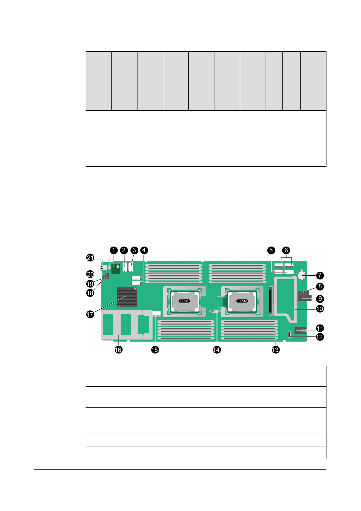
Figure 2-16 CH121 V5 mainboard
1
3 PCIe riser module connector
5 Mezzanine card 2 connector 6 Mezzanine card 1 connector
TPM connector 2 PCIe riser module connector
(PCIe 3.0 x16)
4 RAID controller card
(x8)
connectors
7 BIOS battery 8 Positioning sleeve
9 Backplane signal connector 10 Mezzanine card bracket
11 Power connector 12 SoftRAID key connector
Issue 06 (2019-08-10) Copyright © Huawei Technologies Co., Ltd. 23
Page 32

FusionServer Pro CH121 V5 Compute Node
User Guide
13 Memory slots 14 CPU 2 OPA sideband signal
15 Drive backplane connector 16 Drive cage
17 PCH 18 HLY indicator
19 UID button/indicator 20 Power button/indicator
21 USB 3.0 ports - -
2 Hardware Description
port
Issue 06 (2019-08-10) Copyright © Huawei Technologies Co., Ltd. 24
Page 33

FusionServer Pro CH121 V5 Compute Node
User Guide
3.1 Power-Off Procedure
3.2 Power-On Procedure
3.3 Removing a CH121 V5
3 Basic Operations
3 Basic Operations
3.4 Installing a CH121 V5
3.5 Removing the Cover
3.6 Installing the Cover
3.7 Removing the Air Ducts
3.8 Installing the Air Duct
3.9 Removing the PCIe Card Panel
3.10 Installing the PCIe Card Panel
3.11 Removing a PCIe Card
3.12 Installing a PCIe Card
3.13 Removing a SAS/SATA Drive
3.14 Installing a SAS/SATA Drive
3.15 Removing an NVMe Drive
3.16 Installing an NVMe Drive
Issue 06 (2019-08-10) Copyright © Huawei Technologies Co., Ltd. 25
Page 34

FusionServer Pro CH121 V5 Compute Node
User Guide
3.1 Power-Off Procedure
NOTE
l Powering off a compute node will interrupt all services and programs running on it. Therefore,
before powering off a compute node, ensure that all services and programs have been stopped or
migrated to other compute nodes.
l The "power-off" mentioned here is an operation performed to change the compute node to the
standby state (the power indicator is steady yellow).
l After a compute node is powered off forcibly, wait for more than 10 seconds for the compute node to
power off completely. Do not power on the compute node again before it is completely powered off.
l Forced power-off may damage user programs or unsaved data. Exercise caution when performing
this operation.
The compute node can be powered off in any of the following ways:
l Power off the chassis.
The compute node will be powered off along with the chassis.
l Press the power button on the compute node front panel to power off the compute node
gracefully.
For details, see 2.1.2 Indicators and Buttons.
l Hold down the power button on the compute node front panel for six seconds to power
off the compute node forcibly.
For details, see 2.1.2 Indicators and Buttons.
l Use the MM910 WebUI.
For details, see MM910 Management Module V100R001 User Guide.
l On the MM910 CLI, run the following command:
powerstate
For details, see MM910 Management Module V100R001 Command Reference.
3 Basic Operations
The following describes how to power off a compute node using the MM910 WebUI.
Procedure
Step 1 Back up service data of the compute node.
Step 2 Log in to the MM910 WebUI.
For details, see 12.3 Logging In to the MM910 WebUI.
Step 3 On the HMM WebUI, choose PSUs&FANs.
The PSUs&Fans page is displayed.
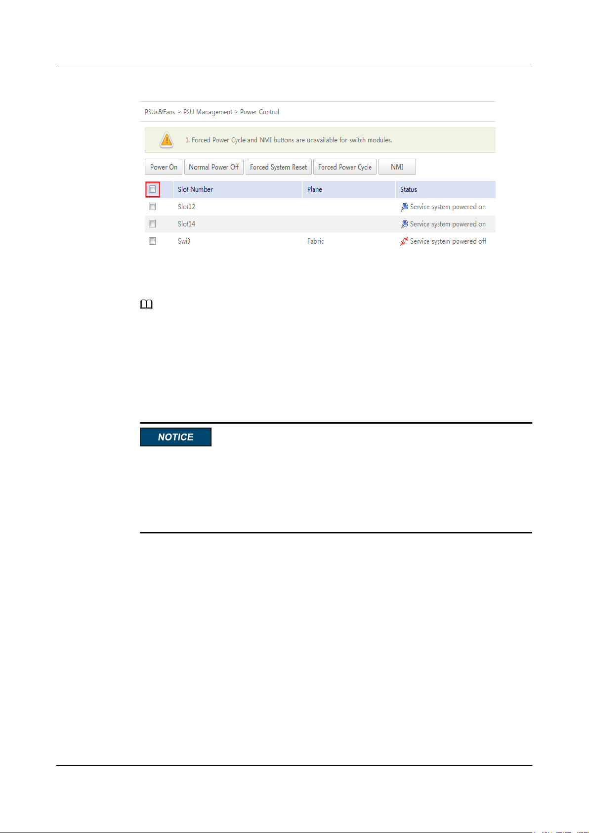
Step 4 Choose PSU Management > Power Control from the navigation tree.
Issue 06 (2019-08-10) Copyright © Huawei Technologies Co., Ltd. 26
Page 35
FusionServer Pro CH121 V5 Compute Node
User Guide
Figure 3-1 Power Control
Step 5 Select the compute node to be powered off, and click Normal Power Off.
The selected compute node will be powered off.
NOTE
To power off all compute nodes at a time, select the check box in the header row and click Normal
Power Off.
3 Basic Operations
----End
3.2 Power-On Procedure
l Before powering on a compute node, ensure that the PSUs are switched off, all cables are
connected correctly, and the power supply voltage meets service requirements.
l During the power-on process, do not remove and insert drives or disconnect and connect
network cables or Console port cables.
l If a compute node is powered off, wait for at least one minute before powering it on again.
The compute node can be powered on in any of the following ways:
l If the compute node is installed but the chassis is not yet powered on, power on the
chassis.
The compute node will be powered on along with the chassis.
l If the chassis is powered on but the compute node is not installed, install the compute
node.
The compute node will be automatically powered on after it is installed.
l If the chassis is powered on but the compute node is not running properly, hold the
power button the front panel for six seconds to power off the compute node forcibly, and
then press the power button to power it on.
l If the chassis is powered on and the compute node is in standby state (the power
indicator is steady yellow), you can use any of the following methods to power on the
compute node:
– Use the MM910 WebUI.
Issue 06 (2019-08-10) Copyright © Huawei Technologies Co., Ltd. 27
Page 36
FusionServer Pro CH121 V5 Compute Node
User Guide
For details, see MM910 Management Module V100R001 User Guide.
– On the MM910 CLI, run the following command:
powerstate
For details, see MM910 Management Module V100R001 Command Reference.
The following describes how to power on a compute node using the MM910 WebUI.
Procedure
Step 1 Check that the chassis is installed, the power cables are correctly connected, and the PSUs and
fan modules are in position.
Step 2 Log in to the MM910 WebUI.
For details, see 12.3 Logging In to the MM910 WebUI.
Step 3 On the HMM WebUI, choose PSUs&FANs.
The PSUs&Fans page is displayed.
3 Basic Operations
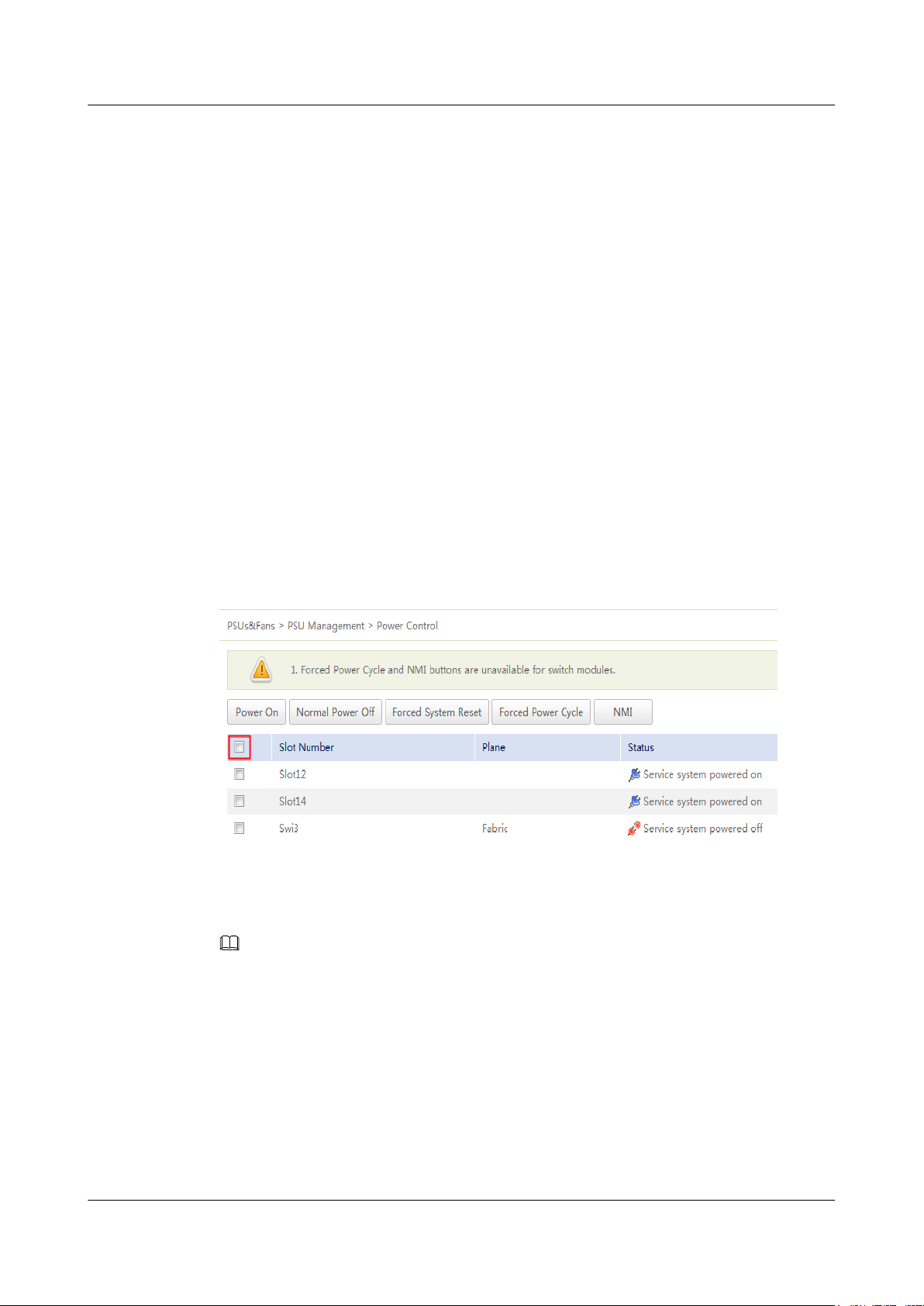
Step 4 Choose PSU Management > Power Control from the navigation tree.
Figure 3-2 Power Control
Step 5 Select the compute node to be powered on, and click Power On.
The selected compute node will be powered on.
NOTE
To power on all compute nodes at a time, select the check box in the header row and click Power On.
----End
3.3 Removing a CH121 V5
Procedure
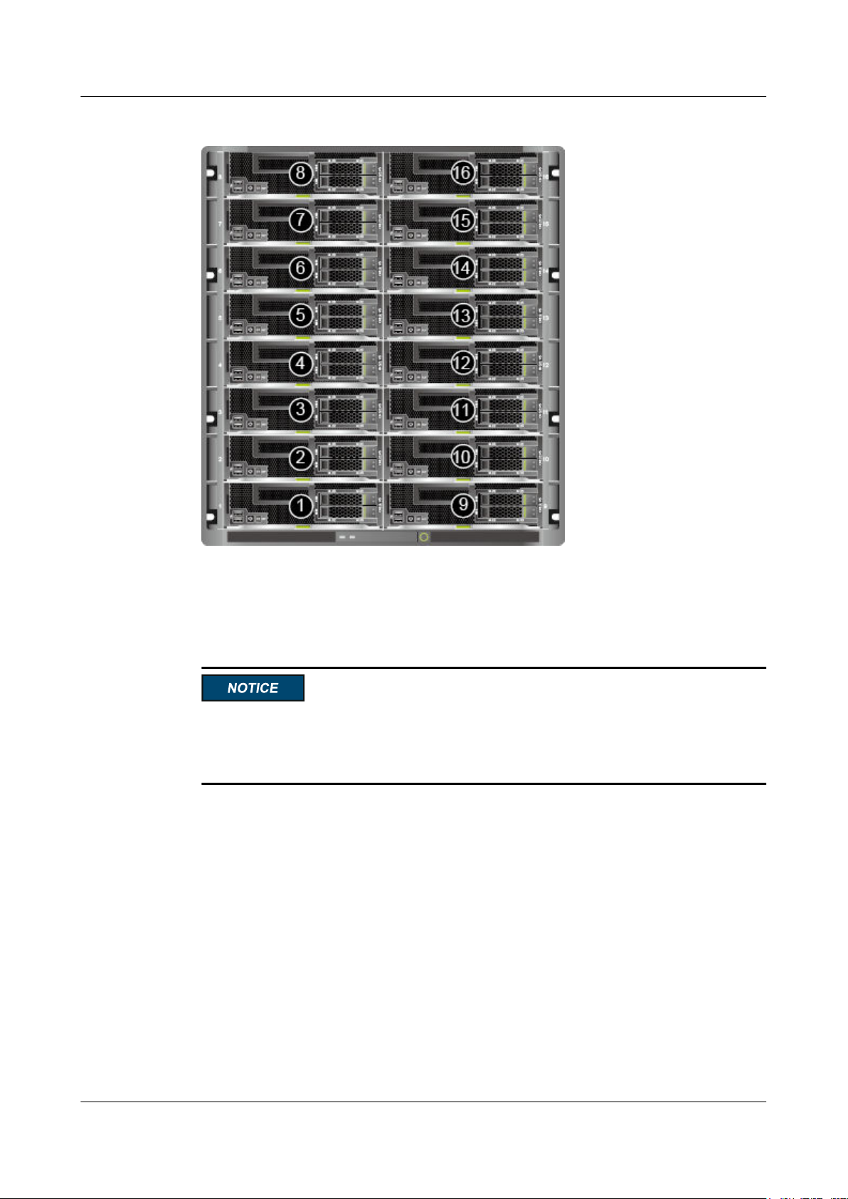
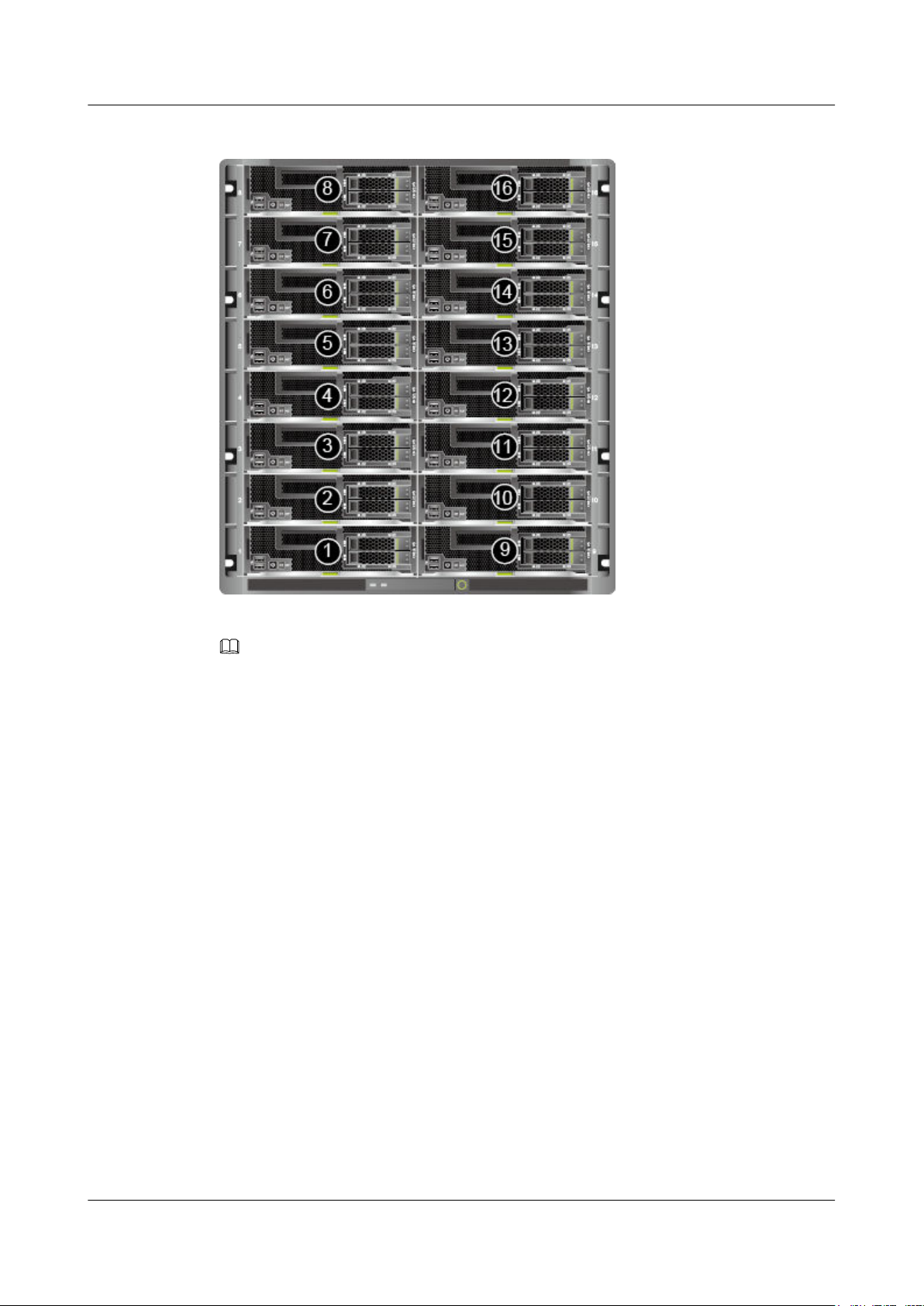
Step 1 Determine the position of the compute node in the chassis.
Issue 06 (2019-08-10) Copyright © Huawei Technologies Co., Ltd. 28
Page 37
FusionServer Pro CH121 V5 Compute Node
User Guide
Figure 3-3 Positions and slot numbers of the CH121 V5 compute nodes
3 Basic Operations
Step 2 Power off the compute node.
For details, see 3.1 Power-Off Procedure.
Step 3 Remove the compute node.
l When removing a device, wear protective gloves to avoid burns.
l To prevent device damage or personal injury, hold the bottom of the device with both
hands when removing it.
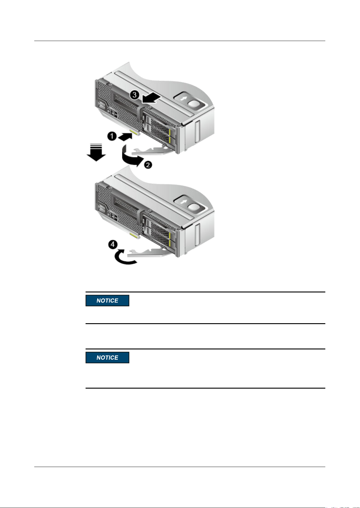
1. Press the ejector release button on the compute node. See (1) in Figure 3-4.
2. Fully open the ejector lever. See (2) in Figure 3-4.
3. Holding the ejector lever, pull the compute node out of the chassis horizontally. See (3)
in Figure 3-4.
4. Close the ejector lever. See (4) in Figure 3-4.
Issue 06 (2019-08-10) Copyright © Huawei Technologies Co., Ltd. 29
Page 38
FusionServer Pro CH121 V5 Compute Node
User Guide
Figure 3-4 Removing a compute node
3 Basic Operations
Step 4 Place the removed compute node in an ESD bag.
Place only one compute node in an ESD bag.
Step 5 Install filler panels.
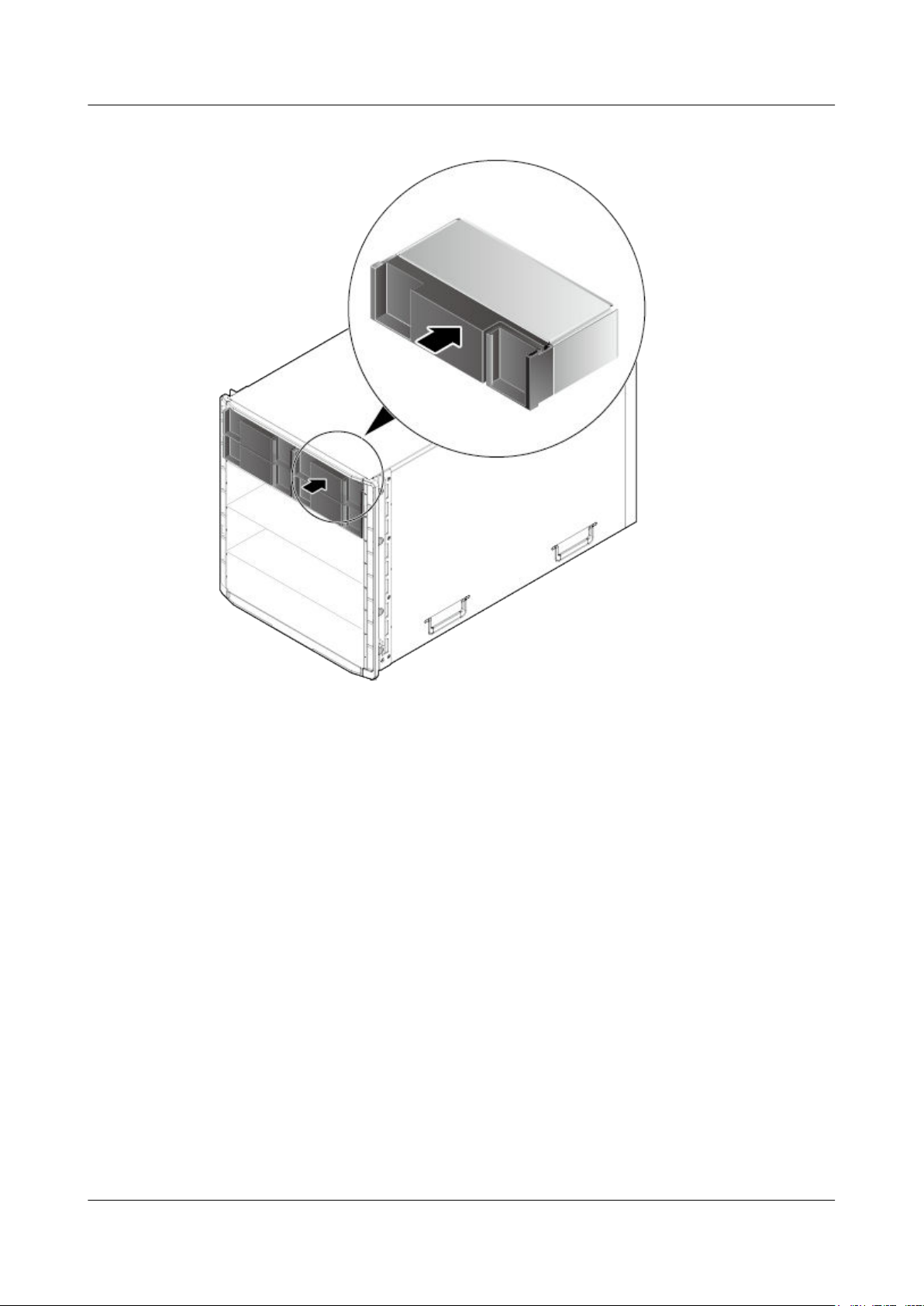
Install filler panels in vacant slots. Otherwise, the ventilation, heat dissipation,
electromagnetic shielding, and dustproof effects of the chassis will be affected.
Insert the filler panel into the chassis horizontally until it clicks into place.
Issue 06 (2019-08-10) Copyright © Huawei Technologies Co., Ltd. 30
Page 39
FusionServer Pro CH121 V5 Compute Node
User Guide
Figure 3-5 Installing a filler panel
3 Basic Operations
----End
3.4 Installing a CH121 V5
Procedure
Step 1 Determine the position of the compute node in the chassis.
Issue 06 (2019-08-10) Copyright © Huawei Technologies Co., Ltd. 31
Page 40
FusionServer Pro CH121 V5 Compute Node
User Guide
Figure 3-6 Positions and slot numbers of the CH121 V5 compute nodes
3 Basic Operations
Step 2 Remove filler panels.
NOTE
Perform this operation only when filler panels are installed.
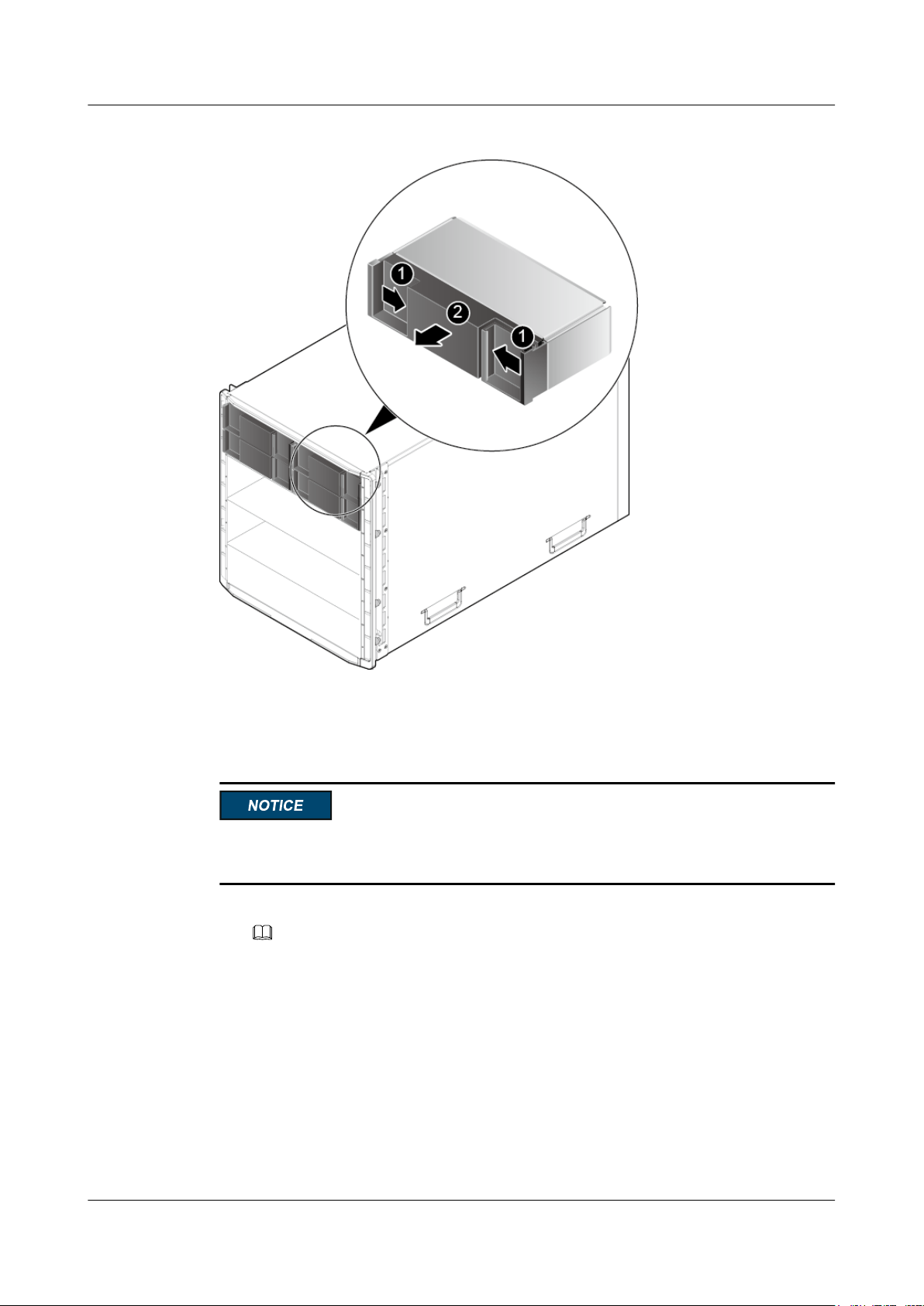
1. Press and hold the groove inward on the filler panel to release the filler panel. See (1) in
Figure 3-7.
2. Remove the filler panel from the chassis. See (1) in Figure 3-7.
Issue 06 (2019-08-10) Copyright © Huawei Technologies Co., Ltd. 32
Page 41
FusionServer Pro CH121 V5 Compute Node
User Guide
Figure 3-7 Removing a filler panel
3 Basic Operations
3. Place the removed filler panel in an accessory recycle bin.
Step 3 Install the compute node.
To prevent device damage or personal injury, hold the bottom of the device with both hands
when installing it.
1. Install a partition board.
NOTE
Install a partition board between two half-width compute nodes. Perform this operation only when
no partition board is installed between two half-width compute nodes.
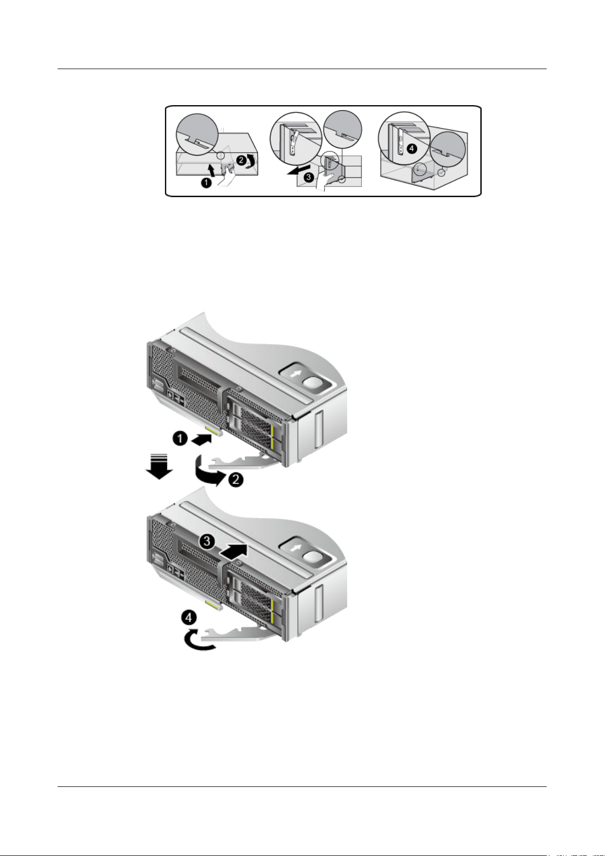
a. Tilt the partition board to the chassis, insert it into the installation holes, and make it
upright. See (1) and (2) in Figure 3-8.
b. Pull the partition board outwards. See (3) and (4) in Figure 3-8.
The partition board is properly installed when you hear a click.
Issue 06 (2019-08-10) Copyright © Huawei Technologies Co., Ltd. 33
Page 42
FusionServer Pro CH121 V5 Compute Node
User Guide
Figure 3-8 Installing a partition board
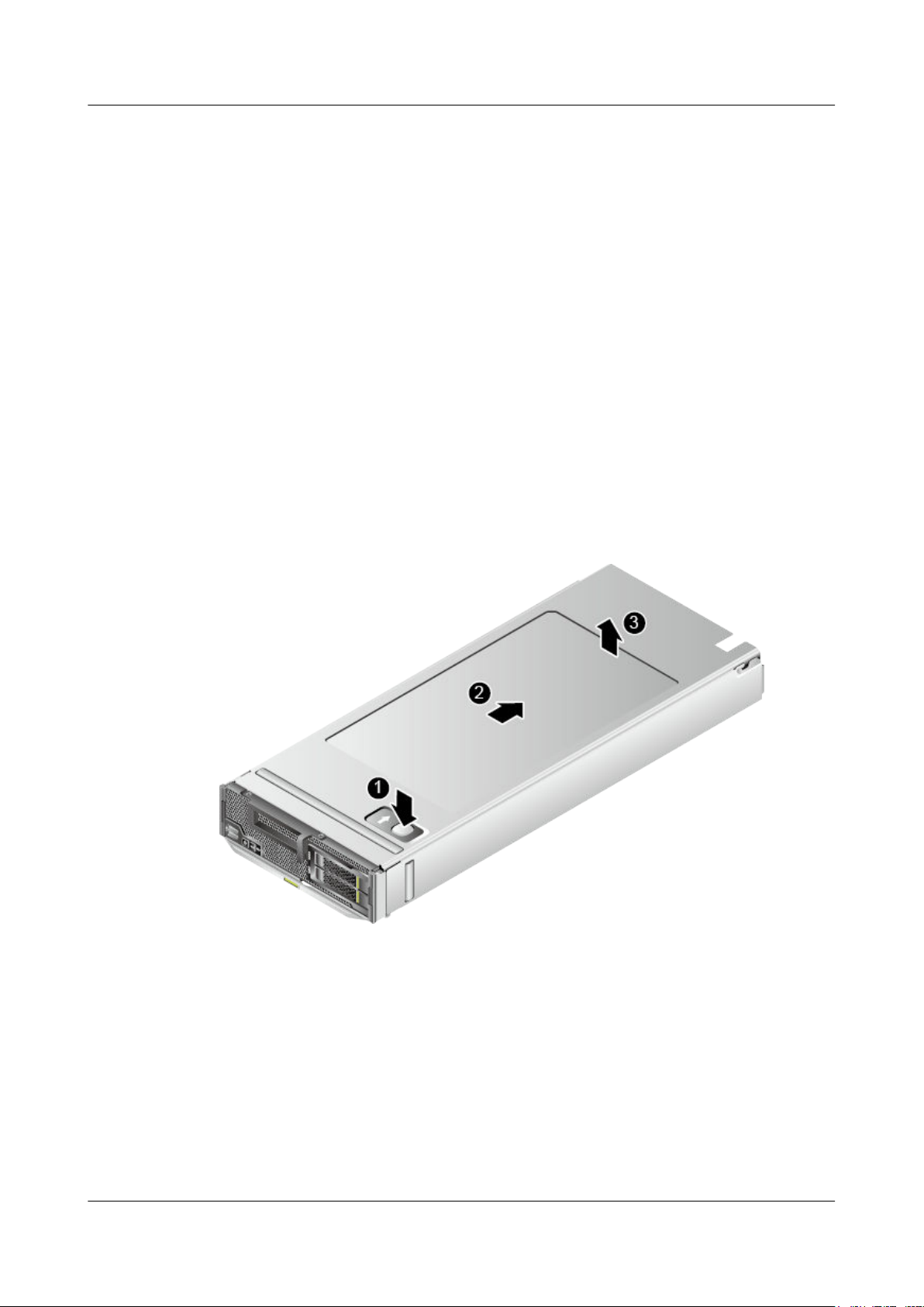
2. Press the ejector release button on the compute node. See (1) in Figure 3-9.
3. Fully open the ejector lever. See (2) in Figure 3-9.
4. Slide the compute node into the chassis horizontally. See (3) in Figure 3-9.
5. Close the ejector lever. See (4) in Figure 3-9.
Figure 3-9 Installing a compute node
3 Basic Operations
Step 4 Power on the compute node.
For details, see 3.2 Power-On Procedure.
Step 5 Check indicator status.
For details, see 2.1.2 Indicators and Buttons.
----End
Issue 06 (2019-08-10) Copyright © Huawei Technologies Co., Ltd. 34
Page 43
FusionServer Pro CH121 V5 Compute Node
User Guide
3.5 Removing the Cover
Procedure
Step 1 Power off the compute node.
For details, see 3.1 Power-Off Procedure.
Step 2 Remove the compute node.
For details, see 3.3 Removing a CH121 V5.
Step 3 Place the compute node on the ESD workstation.
Step 4 Remove the cover.
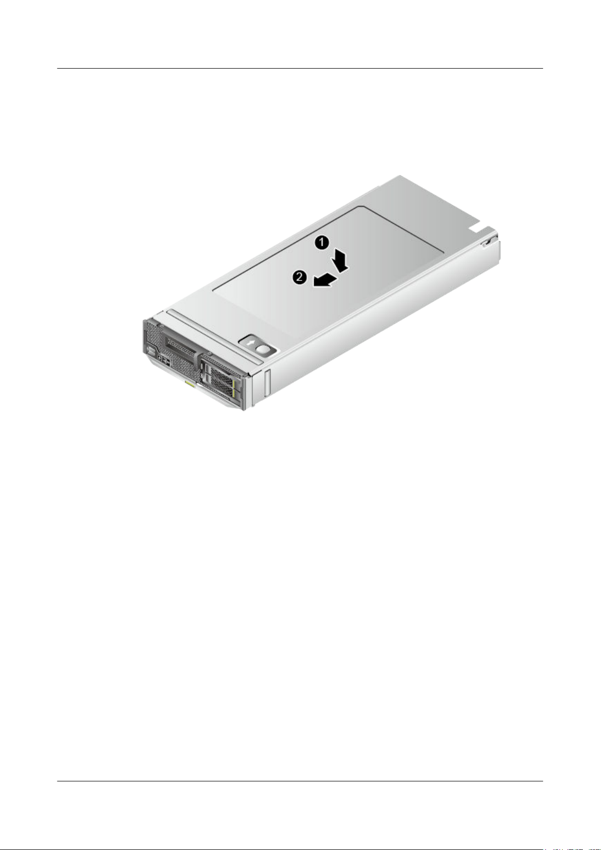
1. Press the button on the cover and push the cover backwards as far as it will go. See (1)
and (2) in Figure 3-10.
2. Lift the chassis cover. See (3) in Figure 3-10.
3 Basic Operations
Figure 3-10 Removing the cover
----End
3.6 Installing the Cover
Procedure
Step 1 Place the compute node on the ESD workstation.
Step 2 Take the spare part out of its ESD bag.
Step 3 Install the cover.
Issue 06 (2019-08-10) Copyright © Huawei Technologies Co., Ltd. 35
Page 44
FusionServer Pro CH121 V5 Compute Node
User Guide
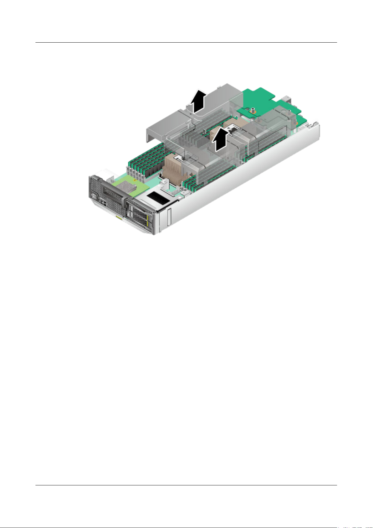
1. Aligning the notches on the cover with the nail heads on the chassis base, vertically place
the cover onto the compute node. See (1) in Figure 3-11.
2. Push the cover towards the front panel of the compute node until the cover clicks into
place. See (2) in Figure 3-11.
Figure 3-11 Installing the cover
3 Basic Operations
Step 4 Install the compute node.
For details, see 3.4 Installing a CH121 V5.
Step 5 Power on the compute node.
For details, see 3.2 Power-On Procedure.
----End
3.7 Removing the Air Ducts
Procedure
Step 1 Power off the compute node.
For details, see 3.1 Power-Off Procedure.
Step 2 Remove the compute node.
For details, see 3.3 Removing a CH121 V5.
Step 3 Place the compute node on the ESD workstation.
Step 4 Remove the cover.
For details, see 3.5 Removing the Cover.
Step 5 Determine the position of the air duct.
Issue 06 (2019-08-10) Copyright © Huawei Technologies Co., Ltd. 36
Page 45
FusionServer Pro CH121 V5 Compute Node
User Guide
Step 6 Lift the left and right air ducts.
Figure 3-12 Removing the air ducts
3 Basic Operations
Step 7 Place the removed component in an ESD bag.
----End
3.8 Installing the Air Duct
Procedure
Step 1 Power off the compute node.
For details, see 3.1 Power-Off Procedure.
Step 2 Remove the compute node.
For details, see 3.3 Removing a CH121 V5.
Step 3 Place the compute node on the ESD workstation.
Step 4 Remove the cover.
For details, see 3.5 Removing the Cover.
Step 5 Take the spare part out of its ESD bag.
Step 6 Determine the position of the air duct.
Step 7 Check whether a PCIe card is installed.
l If yes, go to Step 8.
l If no, go to Step 9.
Step 8 Transform the air duct.
Issue 06 (2019-08-10) Copyright © Huawei Technologies Co., Ltd. 37
Page 46
FusionServer Pro CH121 V5 Compute Node
User Guide
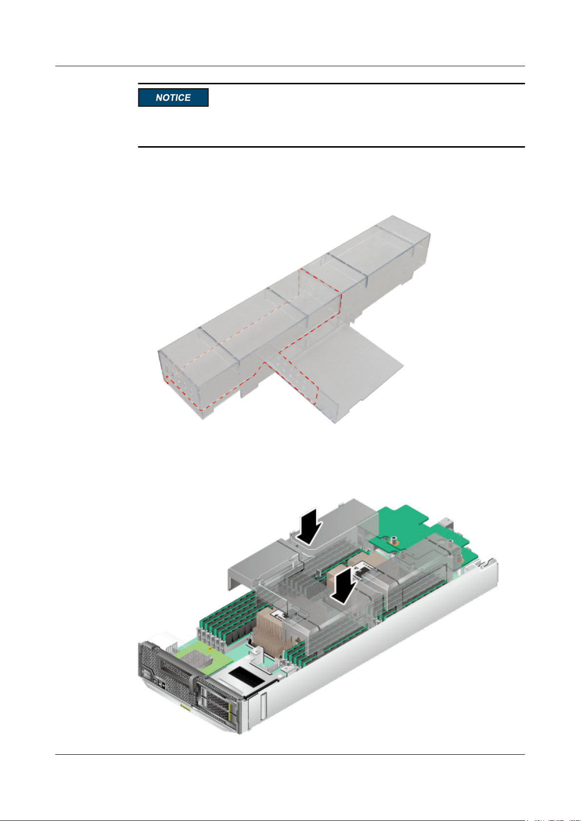
A transformed air duct cannot be used in compute nodes without PCIe cards any more. Please
exercise caution.
Split the left air duct along the dotted line.
Figure 3-13 Transforming the air duct
3 Basic Operations
Step 9 Align the right air duct with the right DIMMs, align the left air duct with the left DIMMs and
heat sinks, and vertically place the air ducts downwards.
Figure 3-14 Installing the air duct
Issue 06 (2019-08-10) Copyright © Huawei Technologies Co., Ltd. 38
Page 47
FusionServer Pro CH121 V5 Compute Node
User Guide
Step 10 Install the cover.
For details, see 3.6 Installing the Cover.
Step 11 Install the compute node.
For details, see 3.4 Installing a CH121 V5.
Step 12 Power on the compute node.
For details, see 3.2 Power-On Procedure.
----End
3.9 Removing the PCIe Card Panel
Procedure
Step 1 Power off the compute node.
For details, see 3.1 Power-Off Procedure.
3 Basic Operations
Step 2 Remove the compute node.
For details, see 3.3 Removing a CH121 V5.
Step 3 Place the compute node on the ESD workstation.
Step 4 Remove the cover.
For details, see 3.5 Removing the Cover.
Step 5 Determine the position of the PCIe card panel.
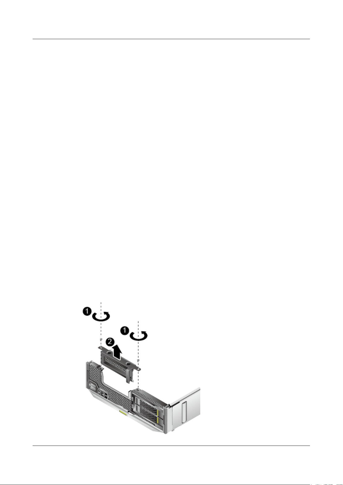
Step 6 Loosen the two screws that secure the PCIe card panel and lift the PCIe card panel vertically.
See (1) and (2) in Figure 3-15.
Figure 3-15 Removing a PCIe card panel
Issue 06 (2019-08-10) Copyright © Huawei Technologies Co., Ltd. 39
Page 48

FusionServer Pro CH121 V5 Compute Node
User Guide
Step 7 Place the removed component in an ESD bag.
----End
3.10 Installing the PCIe Card Panel
Procedure
Step 1 Power off the compute node.
For details, see 3.1 Power-Off Procedure.
Step 2 Remove the compute node.
For details, see 3.3 Removing a CH121 V5.
Step 3 Place the compute node on the ESD workstation.
Step 4 Remove the cover.
For details, see 3.5 Removing the Cover.
3 Basic Operations
Step 5 Check whether a PCIe card is installed.
l If yes, go to Step 6.
l If no, go to Step 7.
Step 6 Remove the PCIe card.
For details, see 3.11 Removing a PCIe Card.
Step 7 Take the spare part out of its ESD bag.
Step 8 Determine the position of the PCIe card panel.
Step 9 Install the PCIe card panel.
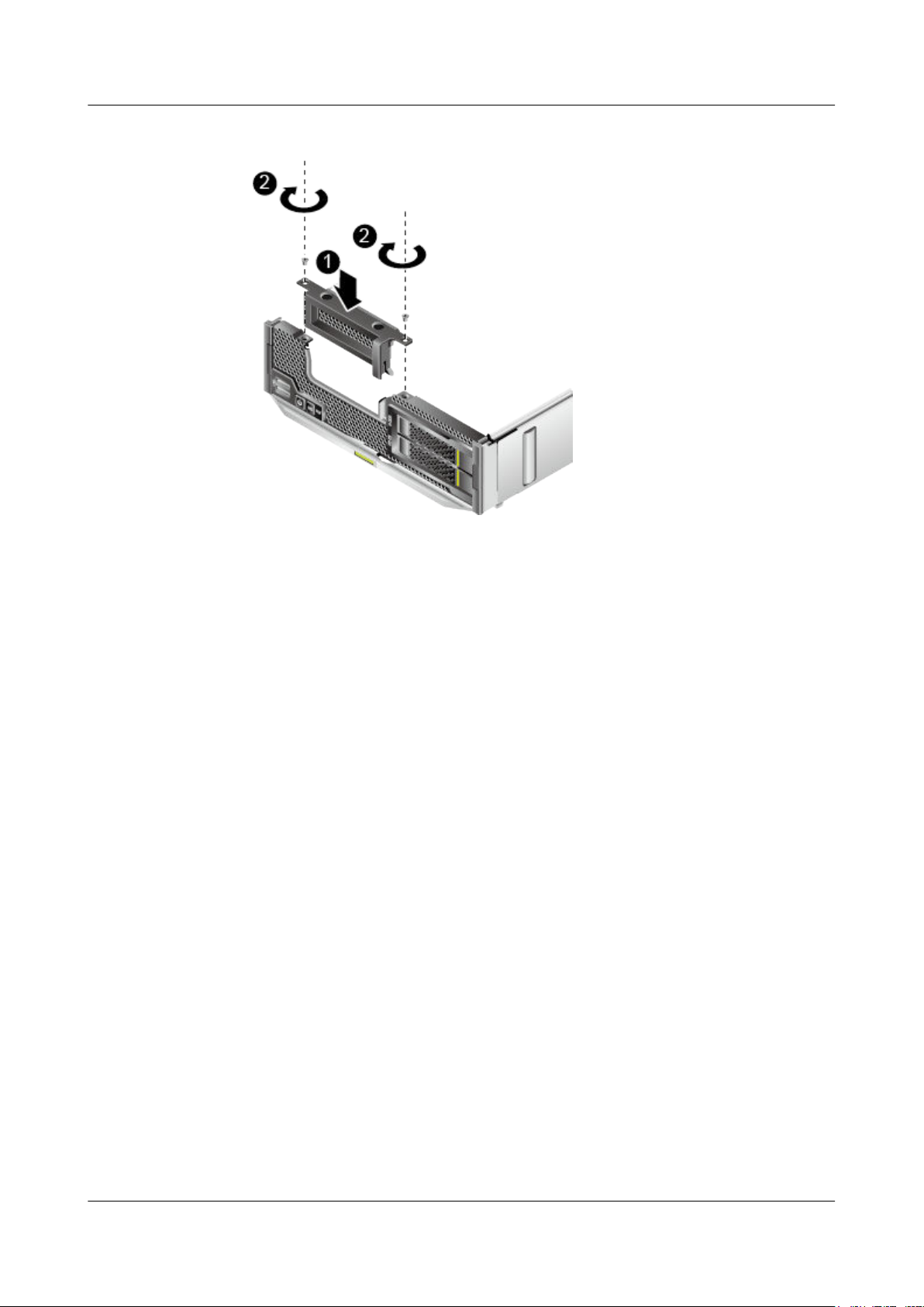
1. Vertically slide the PCIe card panel into the slot, and align the screw holes on the PCIe
card panel with those on the pane. See (1) in Figure 3-16.
2. Tighten the two screws to secure the PCIe card panel. See (2) in Figure 3-16.
Issue 06 (2019-08-10) Copyright © Huawei Technologies Co., Ltd. 40
Page 49
FusionServer Pro CH121 V5 Compute Node
User Guide
Figure 3-16 Installing a PCIe card panel
3 Basic Operations
Step 10 Install the cover.
For details, see 3.6 Installing the Cover.
Step 11 Install the compute node.
For details, see 3.4 Installing a CH121 V5.
Step 12 Power on the compute node.
For details, see 3.2 Power-On Procedure.
----End
3.11 Removing a PCIe Card
Procedure
Step 1 Power off the compute node.
For details, see 3.1 Power-Off Procedure.
Step 2 Remove the compute node.
For details, see 3.3 Removing a CH121 V5.
Step 3 Place the compute node on the ESD workstation.
Step 4 Remove the cover.
For details, see 3.5 Removing the Cover.
Step 5 Remove the air duct.
For details, see 3.7 Removing the Air Ducts.
Issue 06 (2019-08-10) Copyright © Huawei Technologies Co., Ltd. 41
Page 50
FusionServer Pro CH121 V5 Compute Node
User Guide
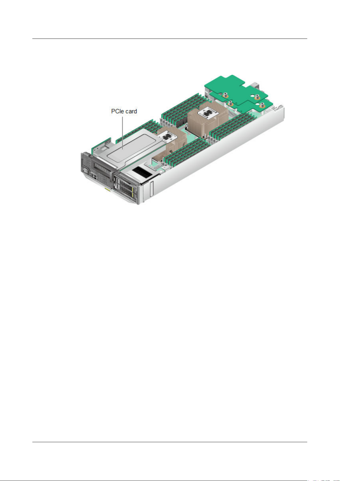
Step 6 Determine the position of the PCIe card.
Figure 3-17 Position of the PCIe card
3 Basic Operations
Step 7 Remove the PCIe card.
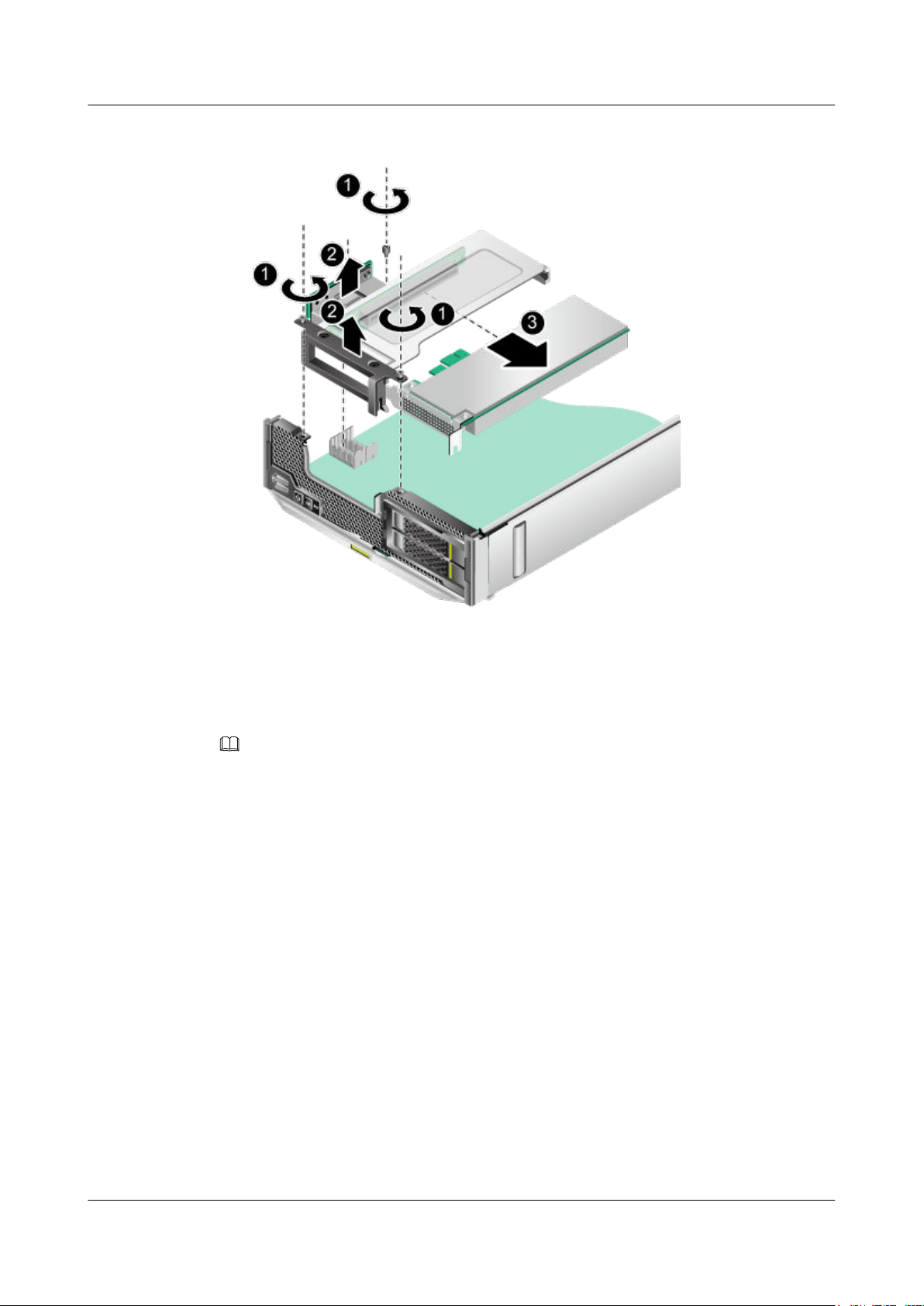
1. Loosen the three screws that secure the PCIe card bracket, and vertically lift the PCIe
card bracket. See (1) and (2) in Figure 3-18.
2. Remove the PCIe card from the PCIe card bracket in the arrow direction. See (3) in
Figure 3-18.
Issue 06 (2019-08-10) Copyright © Huawei Technologies Co., Ltd. 42
Page 51
FusionServer Pro CH121 V5 Compute Node
User Guide
Figure 3-18 Removing a PCIe card
3 Basic Operations
Step 8 Place the removed component in an ESD bag.
Step 9 Install the PCIe card front panel.
For details, see 3.10 Installing the PCIe Card Panel.
NOTE
Perform this operation only when a PCIe card is not installed immediately.
----End
3.12 Installing a PCIe Card
Procedure
Step 1 Power off the compute node.
For details, see 3.1 Power-Off Procedure.
Step 2 Remove the compute node.
For details, see 3.3 Removing a CH121 V5.
Step 3 Place the compute node on the ESD workstation.
Step 4 Remove the cover.
For details, see 3.5 Removing the Cover.
Issue 06 (2019-08-10) Copyright © Huawei Technologies Co., Ltd. 43
Page 52

FusionServer Pro CH121 V5 Compute Node
User Guide
Step 5 Remove the air duct.
For details, see 3.7 Removing the Air Ducts.
Step 6 Remove the PCIe card front panel.
For details, see 3.9 Removing the PCIe Card Panel.
Step 7 Take the spare part out of its ESD bag.
Step 8 Determine the position of the PCIe card.
Figure 3-19 Position of the PCIe card
3 Basic Operations
Step 9 Install the PCIe card.
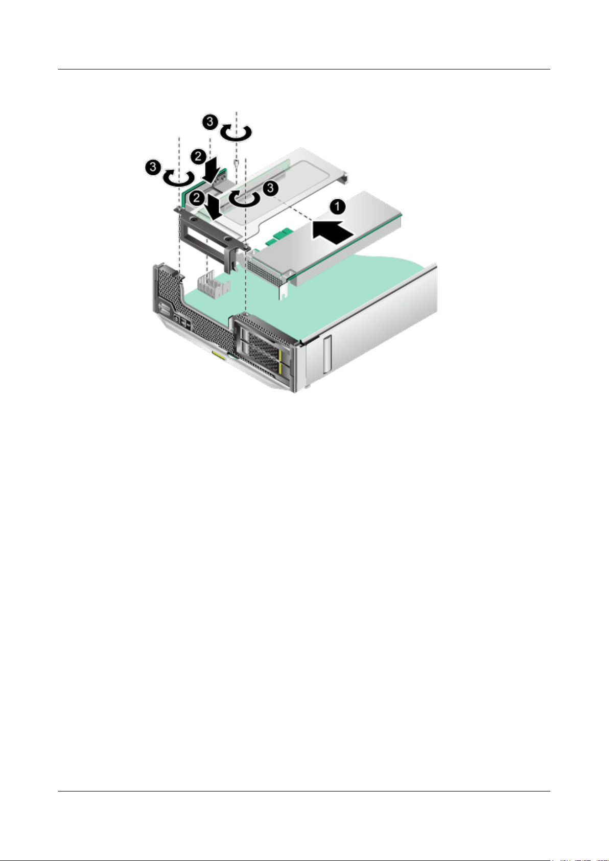
1. Slide the PCIe card into the PCIe card bracket as far as it will go and ensure that the edge
of the PCIe card is flush with the PCIe card bracket. See (1) in Figure 3-20.
2. Install the PCIe card bracket. Ensure that the PCIe card connectors align with the
connectors on the mainboard and the screw holes on the PCIe card filler panel align with
the screw holes on the front panel. See (2) in Figure 3-20.
3. Tighten the three screws to secure the PCIe card bracket. See (3) in Figure 3-20.
Issue 06 (2019-08-10) Copyright © Huawei Technologies Co., Ltd. 44
Page 53
FusionServer Pro CH121 V5 Compute Node
User Guide
Figure 3-20 Installing a PCIe card
3 Basic Operations
Step 10 Install the air duct.
For details, see 3.8 Installing the Air Duct.
Step 11 Install the cover.
For details, see 3.6 Installing the Cover.
Step 12 Install the compute node.
For details, see 3.4 Installing a CH121 V5.
Step 13 Power on the compute node.
For details, see 3.2 Power-On Procedure.
----End
Issue 06 (2019-08-10) Copyright © Huawei Technologies Co., Ltd. 45
Page 54
FusionServer Pro CH121 V5 Compute Node
User Guide
3.13 Removing a SAS/SATA Drive
NOTE
l The SATA or SAS drives support hot swap.
l If the drive to be removed has no operating system installed, you can remove it without
powering off the compute node.
l If the drive to be removed has the operating system installed and is in a RAID array with
redundancy, you can remove it without powering off the compute node.
l If the drive to be removed has the operating system installed but it is not in a RAID array or it
is in a RAID array without redundancy (for example, RAID 0), power off the compute node
before removing it.
l The SAS/SATA drives support RAID configuration.
l If the drive to be removed is not in a RAID array or is in a RAID array without redundancy
(for example, RAID 0), back up the data on the drive before removing it.
l If the drive to be removed is in a RAID array with redundancy, you do not need to back up
data before removing it.
3 Basic Operations
Procedure
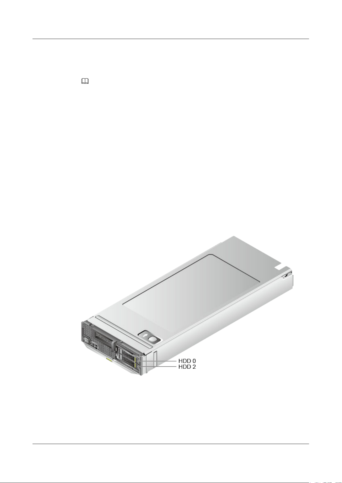
Step 1 Determine the slot and position of the drive.
Figure 3-21 Positions of drives
Step 2 Check the running status of the drive by observing its indicators.
For details, see SAS/SATA Drive Indicators.
Step 3 Determine whether the drive needs to be removed.
l If yes, go to Step 4.
l If no, rectify the drive fault.
Issue 06 (2019-08-10) Copyright © Huawei Technologies Co., Ltd. 46
Page 55
FusionServer Pro CH121 V5 Compute Node
User Guide
Step 4 Remove the drive.
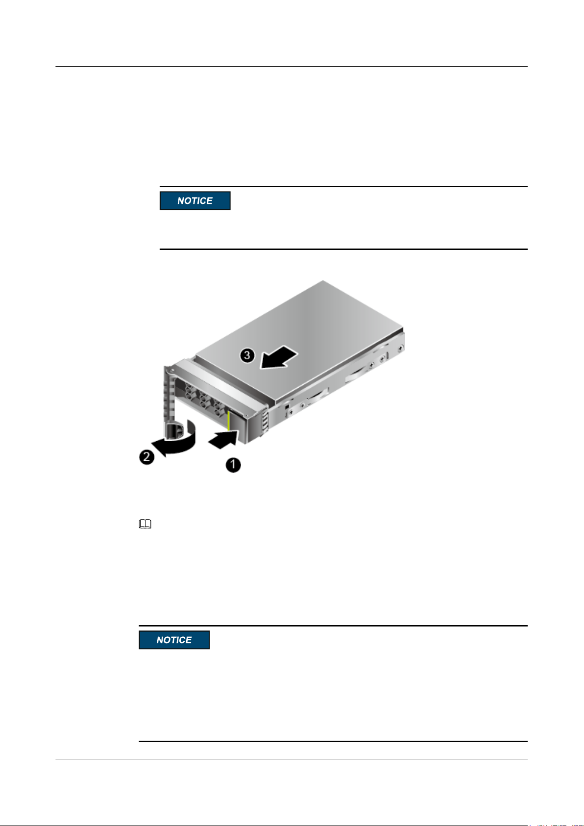
1. Press the ejector release button on the drive panel to release the ejector lever. See (1) in
Figure 3-22.
2. Open the drive ejector lever completely. See (2) in Figure 3-22.
3. Holding the ejector lever of the drive, pull out the drive for about 3 cm (1.18 in.). Wait
for at least 30 seconds and remove the drive from the server. See (3) in Figure 3-22.
Do not insert or remove drives frequently. If a drive is frequently removed and installed
in an interval shorter than 30 seconds, there are risks that the drive cannot be identified.
Figure 3-22 Removing a drive
3 Basic Operations
Step 5 Place the removed component in an ESD bag.
Step 6 Install a drive filler.
NOTE
Perform this operation only when a drive is not installed immediately.
----End
3.14 Installing a SAS/SATA Drive
l The SATA or SAS drives support hot swap. After a faulty drive is disconnected from its
backplane, wait 30 seconds before removing it. The alarm will not be cleared immediately
after a new drive is installed. It will be cleared after the RAID array rebuild is complete.
Do not frequently hot-swap a drive to prevent new alarms.
l To prevent damage caused by insufficient heat dissipation and high temperature, install
components or filler panels.
Issue 06 (2019-08-10) Copyright © Huawei Technologies Co., Ltd. 47
Page 56
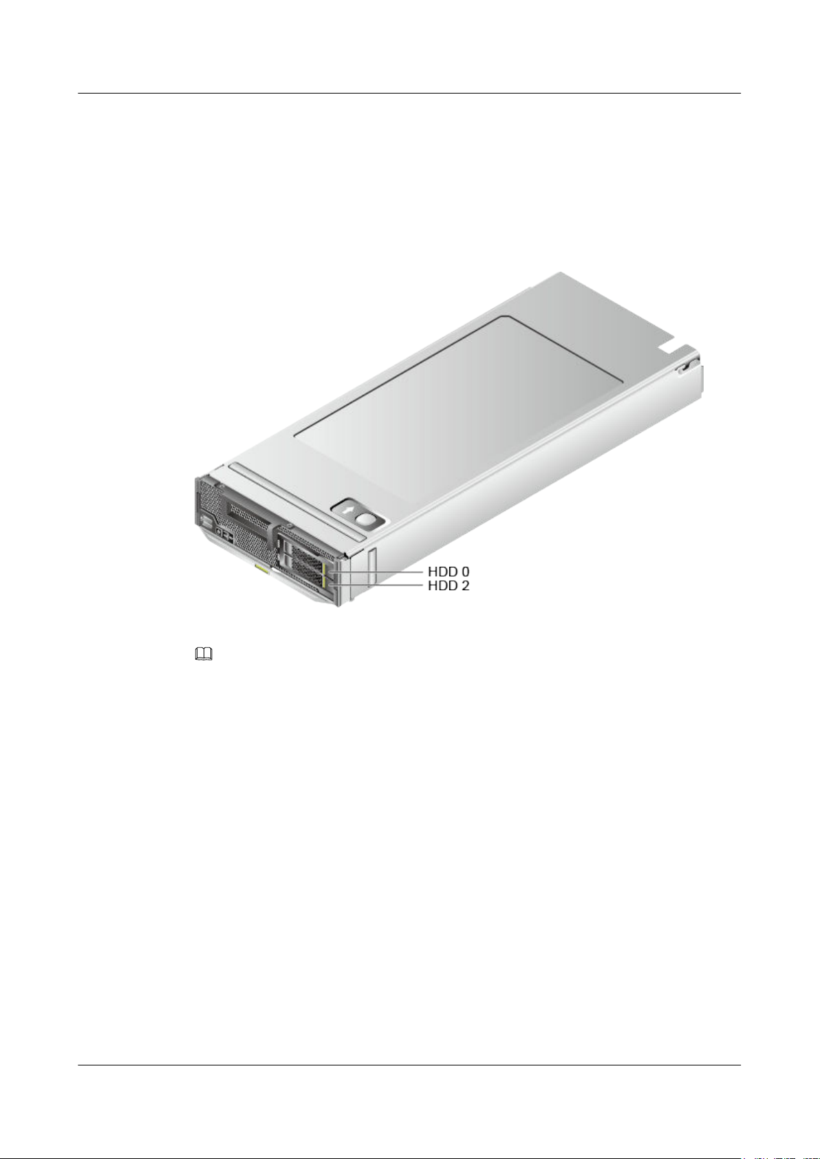
FusionServer Pro CH121 V5 Compute Node
User Guide
Procedure
Step 1 Take the spare part out of its ESD bag.
Step 2 Determine the slot and position of the drive.
For details, see 2.4.1 Drive Configurations and 2.4.2 Drive Numbering.
Figure 3-23 Positions of drives
3 Basic Operations
Step 3 Remove the drive filler.
NOTE
Perform this operation only when a drive filler is installed.
Step 4 Install a drive.
1. Fully open the ejector lever and push the drive into the slot as far as it will go. See (1) in
Figure 3-24.
2. Ensure that the ejector lever is fastened to the chassis beam, and then close it to
completely insert the drive into the slot. See (2) in Figure 3-24.
Issue 06 (2019-08-10) Copyright © Huawei Technologies Co., Ltd. 48
Page 57
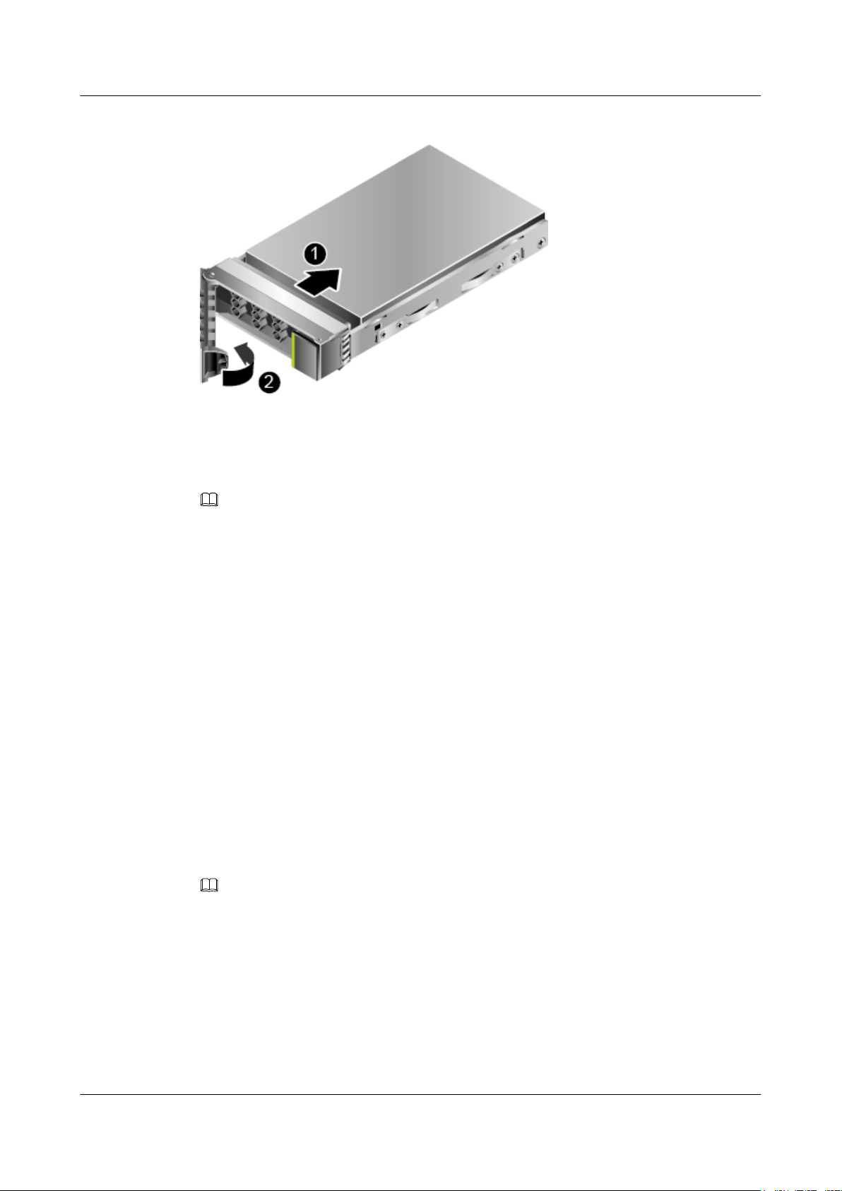
FusionServer Pro CH121 V5 Compute Node
User Guide
Figure 3-24 Installing a drive
Step 5 Check the running status of the drive by observing its indicators.
For details, see SAS/SATA Drive Indicators.
Step 6 Restore the drive data.
3 Basic Operations
NOTE
Perform this operation only when you replace a drive.
For details, see Troubleshooting > Hard Drive Fault in Huawei V5 Server RAID
Controller Card User Guide.
----End
3.15 Removing an NVMe Drive
l If the VMD function is enabled and the latest Intel RSTe driver is installed, the NVMe
drives support surprise hot swap.
– For details about how to enable the VMD function, see 12.9.1 Enabling VMD.
– Install the Intel RSTe driver. For details, see Huawei V5 Server RAID Controller
Card User Guide.
l If the VMD function is disabled, the NVMe drives support only orderly hot swap.
For details about how to disable the VMD function, see 12.9.2 Disabling VMD.
Procedure (VMD Enabled)
NOTE
l Use the Intelligent Computing Compatibility Checker to obtain information about the operating
systems supported by the VMD function.
l Before removing an NVMe drive:
l Stop accessing the NVMe drive.
l Back up date of the NVMe drive to prevent data loss.
l Remove the NVMe drives one by one. Remove the next NVMe drive only after the previous one is
removed completely.
l If the OS is RHEL 7.3 and the VMD function is enabled, the OS kernel 3.10.0-514.el7.x86_64 must
be used for surprise hot swap of NVMe drives. Otherwise, the operating system may restart.
Issue 06 (2019-08-10) Copyright © Huawei Technologies Co., Ltd. 49
Page 58
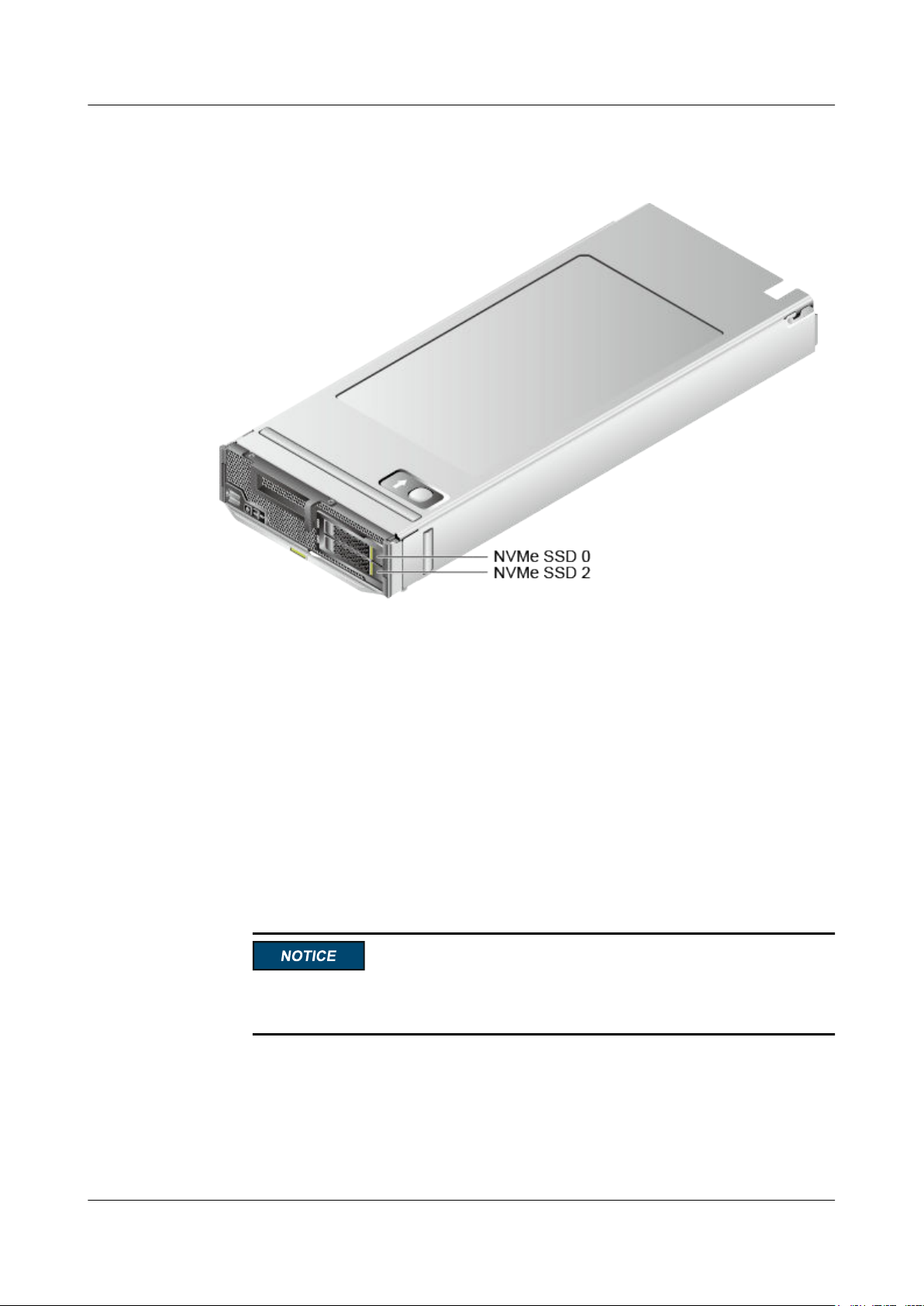
FusionServer Pro CH121 V5 Compute Node
User Guide
Step 1 Determine the slot and position of the drive.
Figure 3-25 Positions of drives
3 Basic Operations
Step 2 Check the running status of the drive by observing its indicators.
For details, see NVMe SSD Indicators.
Step 3 Determine whether the drive needs to be removed.
l If yes, go to Step 4.
l If no, rectify the drive fault.
Step 4 Remove the drive.
1. Press the ejector release button on the drive panel to release the ejector lever. See (1) in
Figure 3-26.
2. Open the drive ejector lever completely. See (2) in Figure 3-26.
3. Holding the ejector lever of the drive, pull out the drive for about 3 cm (1.18 in.). Wait
for at least 30 seconds and remove the drive from the server. See (3) in Figure 3-26.
Do not insert or remove drives frequently. If a drive is frequently removed and installed
in an interval shorter than 30 seconds, there are risks that the drive cannot be identified.
Issue 06 (2019-08-10) Copyright © Huawei Technologies Co., Ltd. 50
Page 59
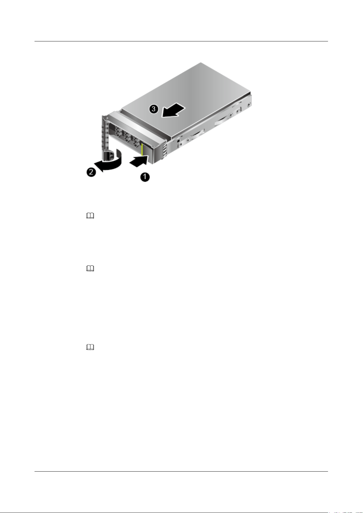
FusionServer Pro CH121 V5 Compute Node
User Guide
Figure 3-26 Removing a drive
Step 5 Place the removed component in an ESD bag.
Step 6 Install a drive filler.
3 Basic Operations
NOTE
Perform this operation only when a drive is not installed immediately.
----End
Procedure (VMD Disabled)
NOTE
l Before removing an NVMe drive:
l Stop accessing the NVMe drive.
l Back up date of the NVMe drive to prevent data loss.
l Remove the NVMe drives one by one. Remove the next NVMe drive only after the previous one is
removed completely.
l Run command to uninstall the drive driver.
Windows OS
NOTE
l Use the Intelligent Computing Compatibility Checker to obtain information about the Windows
operating systems supported.
l The following uses Windows Server 2012 R2 as an example.
Step 1 Determine the slot and position of the drive.
Issue 06 (2019-08-10) Copyright © Huawei Technologies Co., Ltd. 51
Page 60
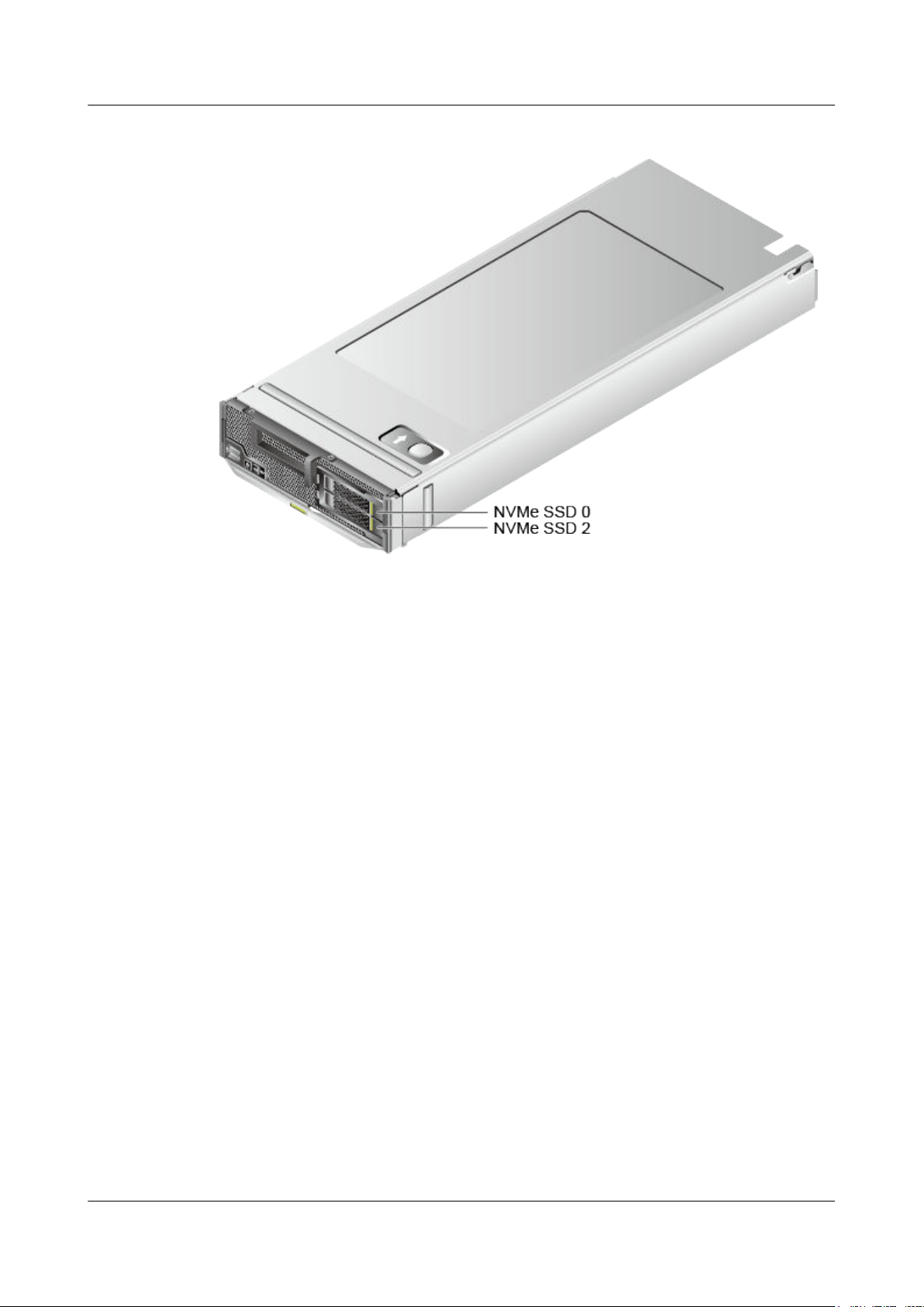
FusionServer Pro CH121 V5 Compute Node
User Guide
Figure 3-27 Positions of drives
3 Basic Operations
Step 2 Check the running status of the drive by observing its indicators.
For details, see NVMe SSD Indicators.
Step 3 Determine whether the drive needs to be removed.
l If yes, go to Step 4.
l If no, rectify the drive fault.
Step 4 Query the mapping between slot IDs and drive letters of NVMe drives.
1. Choose Server Manager > Computer Management > Disk Management.
2. Right-click a drive and choose Properties from the shortcut menu. In the displayed
dialog box, view the slot ID of the drive.
3. Determine whether the drive is an NVMe drive based on the slot ID. If yes, record its
drive letter, as shown in Figure 3-28.
Determine the physical slot of the drive based on the slot ID. Table 3-1 lists the mapping
between the slot IDs and physical slot numbers.
Issue 06 (2019-08-10) Copyright © Huawei Technologies Co., Ltd. 52
Page 61
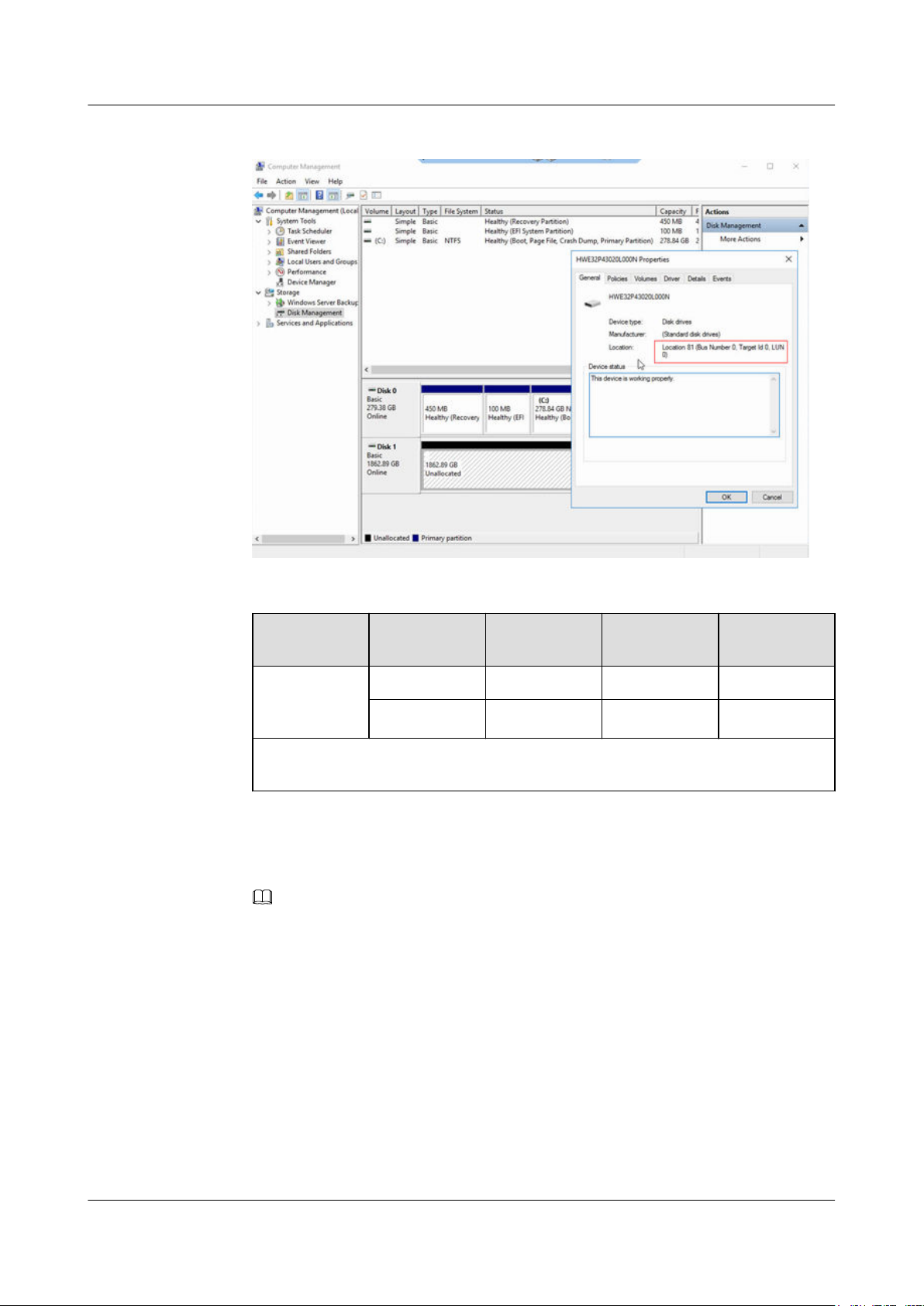
FusionServer Pro CH121 V5 Compute Node
User Guide
Figure 3-28 Mapping between the slot ID and NVMe drive letter
3 Basic Operations
Table 3-1 Mapping between physical slot numbers, B/D/F, and slot IDs
Configuratio
n
24 x 2.5"
Physical Slot
No.
Root Port
(B/D/F)
Device
(B/D/F)
Slot ID
Slot0 85:02.0 86:00.0 80
NVMe drive
configuration
Slot2 85:03.0 87:00.0 81
The Device (B/D/F) values vary depending on the setting of the VMD function. The
values in this table are based on the assumption that the VMD function is disabled.
4. The following uses Huawei NVMe drive as an example to describe how to install the
NVMe driver hiodriver and NVMe tool NVMe Toolbox. The NVMe Toolbox can be
used to query NVMe drive information, upgrade the firmware, and perform hot swap.
NOTE
After installing ES3000 V5 NVMe drives, install the toolkit required by the OS to manage the
drives. The ES3000 V5 tool is incompatible with the built-in NVMe driver of the Windows OS.
Therefore, ensure that you have installed Huawei NVMe driver before using the tool. You can
obtain the tool package from the official Huawei website. For details, see Huawei ES3000 V5
SSD Upgrade Guide.
Step 5 In the program(x86)\hioadm directory of drive C, run NVMe Toolbox 4.0 to view the NVMe
drives in running.
Issue 06 (2019-08-10) Copyright © Huawei Technologies Co., Ltd. 53
Page 62
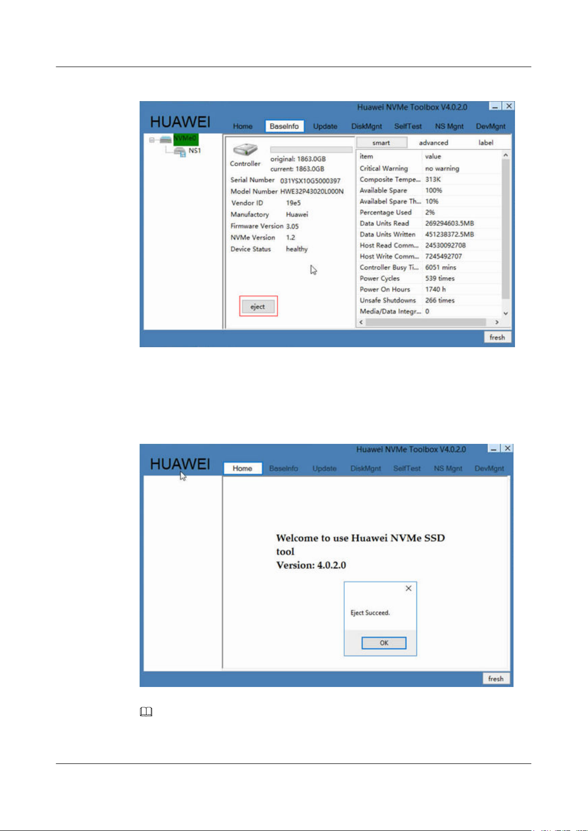
FusionServer Pro CH121 V5 Compute Node
User Guide
Figure 3-29 Viewing running NVMe SSDs
3 Basic Operations
Step 6 Select the NVMe drive to be removed.
Step 7 Click eject.
After the drive is removed, "Eject Succeed" will be displayed.
Figure 3-30 Success message
NOTE
If a failure message is displayed indicating that the NVMe drive is being accessed, stop the related
services and click eject again.
Issue 06 (2019-08-10) Copyright © Huawei Technologies Co., Ltd. 54
Page 63
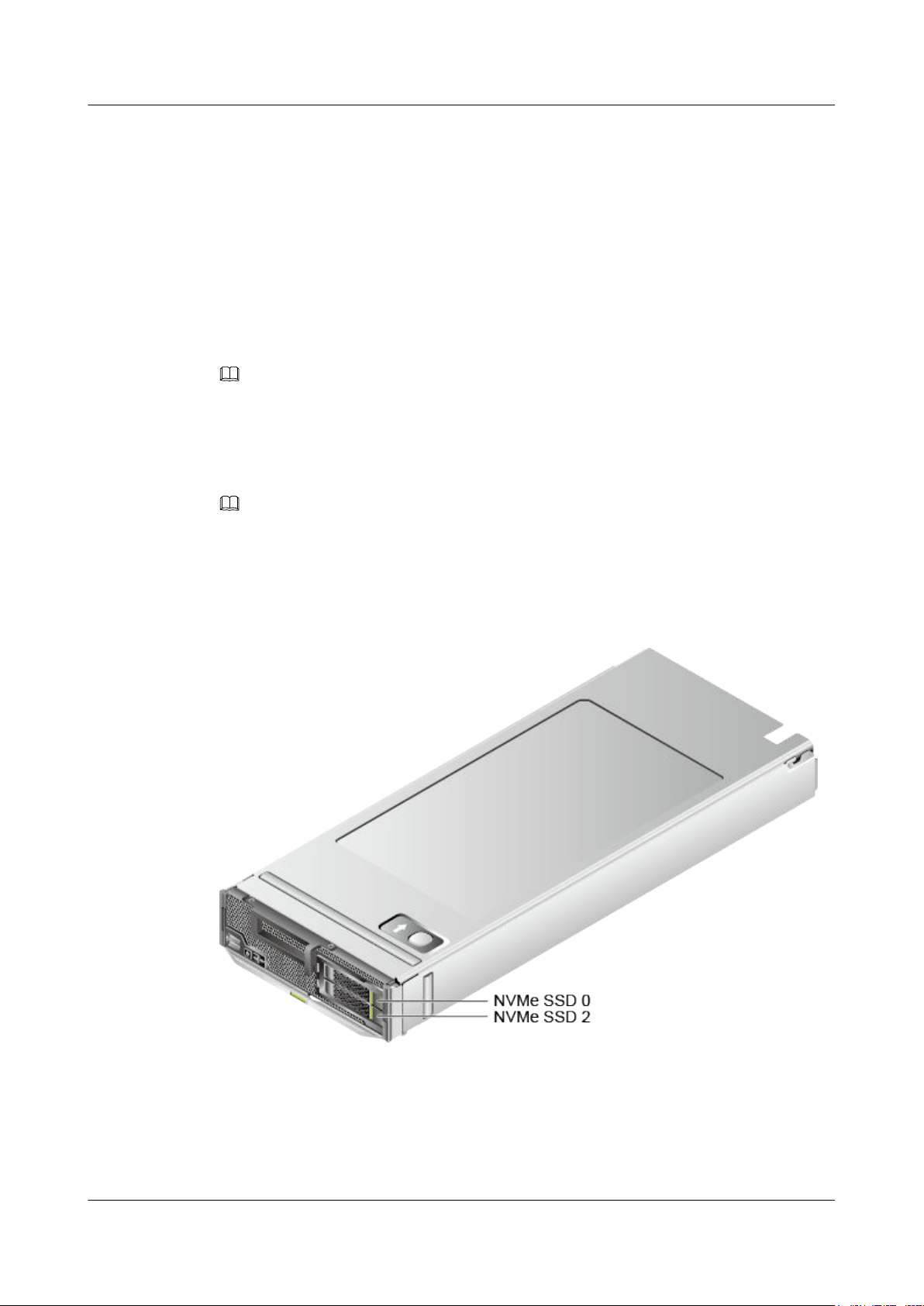
FusionServer Pro CH121 V5 Compute Node
User Guide
Step 8 Click OK.
Step 9 Observe the indicator status of the NVMe drive. If the green indicator is off and the yellow
indicator blinks at 0.5 Hz, remove the NVMe drive slowly.
For details about the drive indicator status, see NVMe SSD Indicators.
For details about how to manually remove an NVMe drive, see 3.13 Removing a SAS/SATA
Drive.
Step 10 Place the removed component in an ESD bag.
Step 11 Install a drive filler.
NOTE
Perform this operation only when a drive is not installed immediately.
----End
Linux OS
NOTE
3 Basic Operations
Use the Intelligent Computing Compatibility Checker to obtain information about the Linux
operating systems supported.
Step 1 Determine the slot and position of the drive.
Figure 3-31 Positions of drives
Step 2 Check the running status of the drive by observing its indicators.
For details, see NVMe SSD Indicators.
Step 3 Determine whether the drive needs to be removed.
l If yes, go to Step 4.
Issue 06 (2019-08-10) Copyright © Huawei Technologies Co., Ltd. 55
Page 64
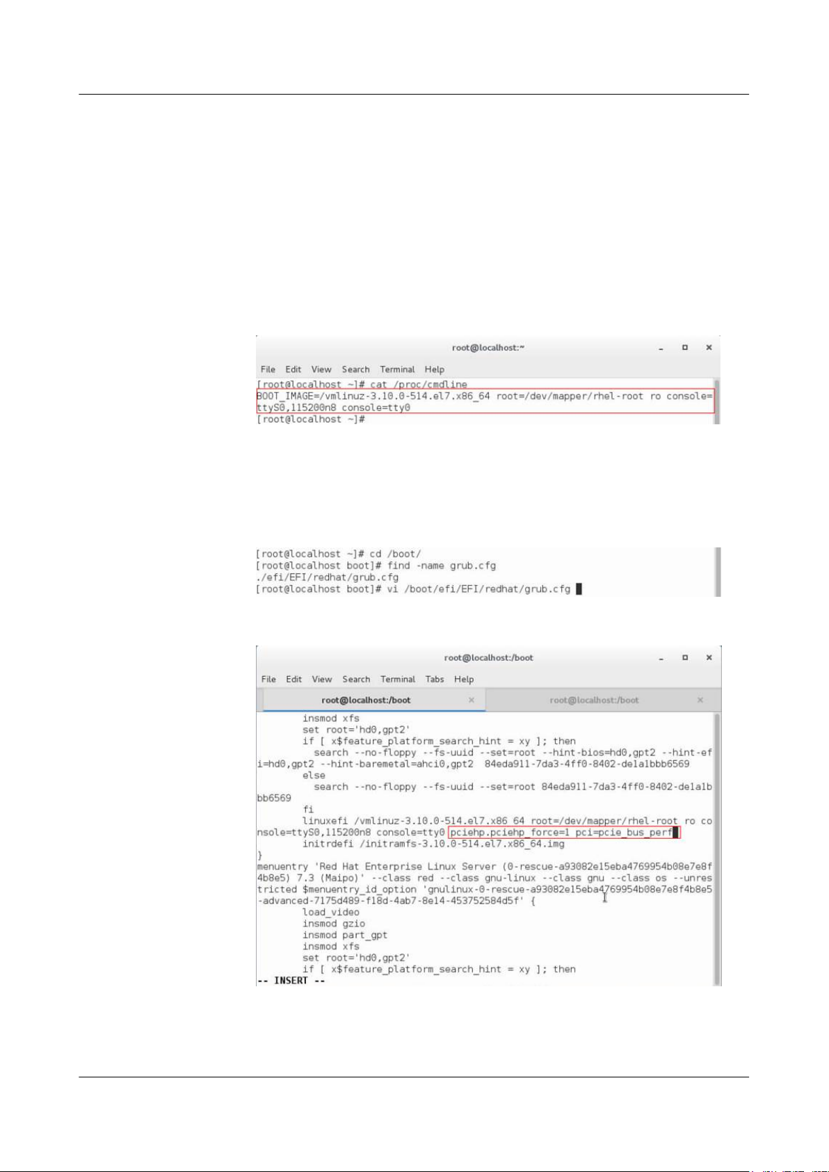
FusionServer Pro CH121 V5 Compute Node
User Guide
l If no, rectify the drive fault.
Step 4 Configure kernel parameters.
Log in to the OS, and open /boot/efi/EFI/redhat/grub.cfg (if the OS is installed in UEFI
mode) or /boot/grub2/grub.cfg (if the OS is installed in legacy mode).
l If RHEL 7.3 is installed in UEFI mode:
a. Run the cat /proc/cmdline command. If the command output does not contain
"pciehp.pciehp_force=1 pci=pcie_bus_perf", you need to configure kernel
parameters.
Figure 3-32 Opening the configuration file
b. Run the vi/boot/efi/EFI/redhat/grub.cfg command. In the command output, find
the sentence that is displayed after the cat/proc/cmdline command is executed in
Step 4.a, and add a space and then "pciehp.pciehp_force=1 pci=pcie_bus_perf" at
the end of the sentence. Do not add the content in a new line.
3 Basic Operations
Figure 3-33 Configuring kernel parameters (1)
Figure 3-34 Configuring kernel parameters (2)
c. Save the file and restart the compute node.
d. Run the cat /proc/cmdline command. If the command output contains
"pciehp.pciehp_force=1 pci=pcie_bus_perf", the kernel is configured successfully.
Issue 06 (2019-08-10) Copyright © Huawei Technologies Co., Ltd. 56
Page 65
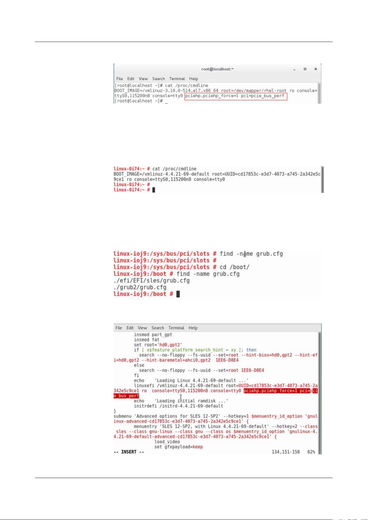
FusionServer Pro CH121 V5 Compute Node
User Guide
Figure 3-35 Checking the configuration
l If SUSE 12.2 is installed in UEFI:
a. Run the cat /proc/cmdline command. If the command output does not contain
"pciehp.pciehp_force=1 pci=pcie_bus_perf", you need to configure kernel
parameters.
Figure 3-36 Opening the configuration file
b. Run the vi /boot/efi/EFI/sles/grub.cfg command. In the command output, find the
sentence that is displayed after the cat/proc/cmdline command is executed in Step
4.a, and add a space and then "pciehp.pciehp_force=1 pci=pcie_bus_perf" at the
end of the sentence. Do not add the content in a new line.
3 Basic Operations
Figure 3-37 Configuring kernel parameters (1)
Figure 3-38 Configuring kernel parameters (2)
c. Save the file and restart the compute node.
Issue 06 (2019-08-10) Copyright © Huawei Technologies Co., Ltd. 57
Page 66
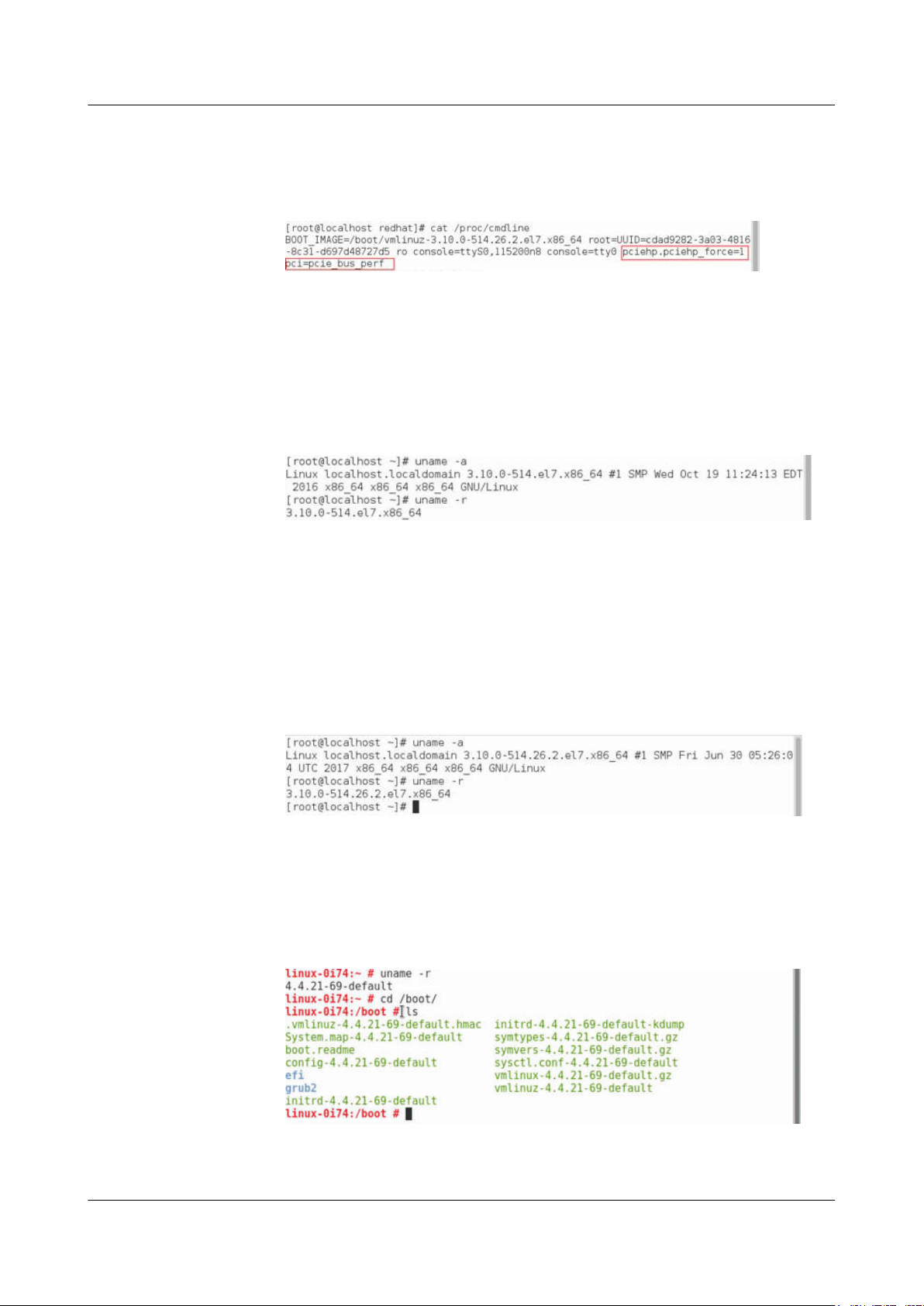
FusionServer Pro CH121 V5 Compute Node
User Guide
d. Run the cat /proc/cmdline command. If the command output contains
"pciehp.pciehp_force=1 pci=pcie_bus_perf", the kernel is configured successfully.
Figure 3-39 Checking the configuration
Step 5 Upgrade the OS kernel.
l Example 1: RHEL 7.3
Upgrade the kernel of RHEL 7.3 to kernel-3.10.0-514.26.2.e17.x86_64 or later to
support orderly hot swap of NVMe drives.
a. Run the uname -r command to check the current kernel version.
Figure 3-40 Kernel version
3 Basic Operations
b. Log in to the official Red Hat website to download the kernel upgrade package
(kernel-3.10.0-514.26.2.e17.x86_64.rpm for example).
c. Run the rpm -ivh kernel-3.10.0-514.26.2.e17.x86_64.rpm command to upload the
upgrade package to the OS for installation.
d. Restart the OS after the installation is complete.
e. Run the uname -r command. If 3.10.0-514.26.2.el7.x86_64 is displayed, the kernel
is upgraded successfully.
Figure 3-41 Checking the kernel version
l Example 2: SUSE 12.2
Upgrade the kernel of SUSE 12.2 to kernel-default-4.4.74-92.32.1.x86_64 or later to
support orderly hot swap of NVMe drives.
a. Run the uname -r command to check the current kernel version.
Figure 3-42 Kernel version
b. Log in to the official SUSE website to download the kernel upgrade package
(kernel-3.10.0-514.26.2.e17.x86_64 for example).
Issue 06 (2019-08-10) Copyright © Huawei Technologies Co., Ltd. 58
Page 67
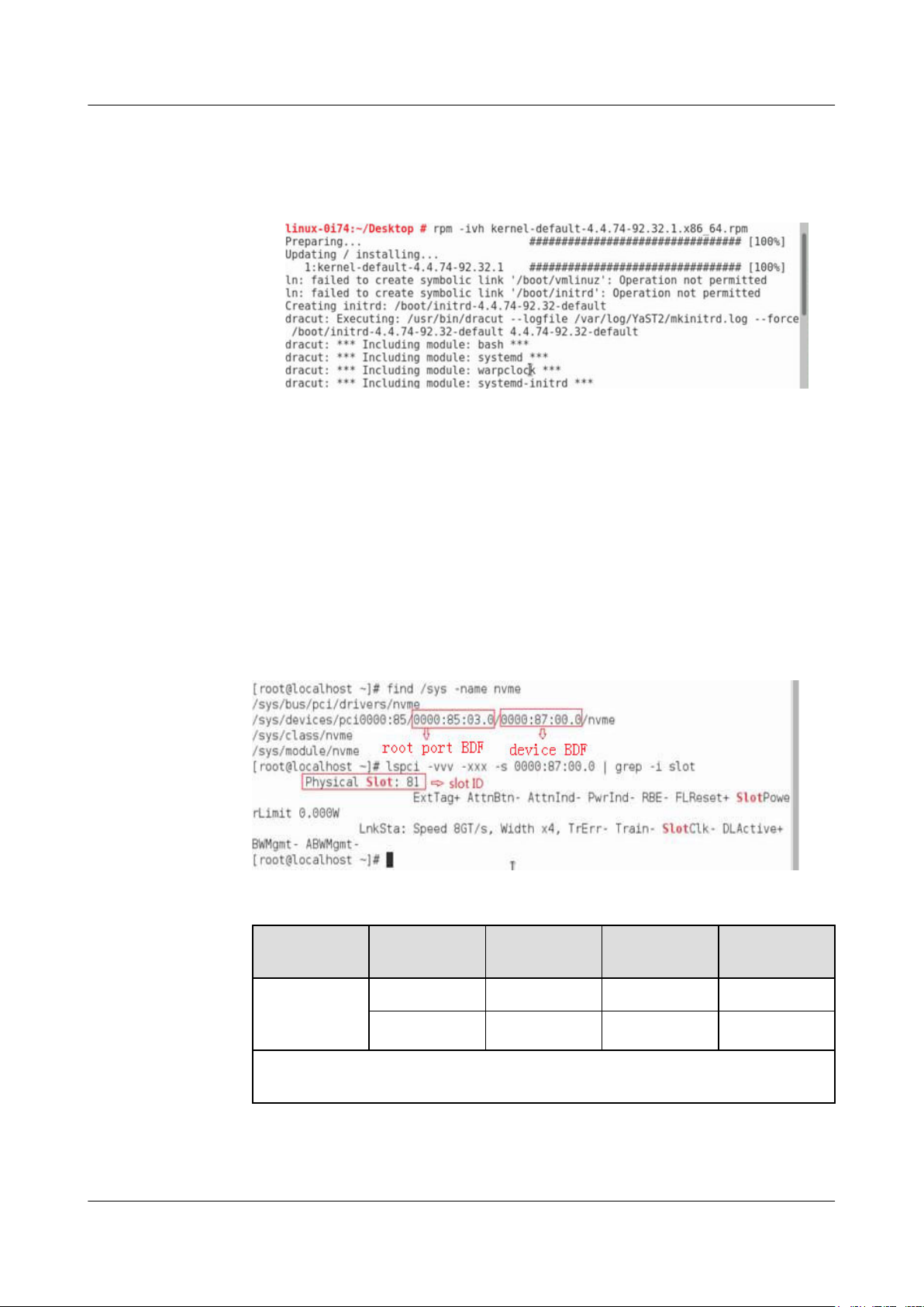
FusionServer Pro CH121 V5 Compute Node
User Guide
c. Run the rpm -ivh kernel-default-4.4.74-92.32.1.x86_64.rpm command to upload
the upgrade package to the OS for installation.
Figure 3-43 Installing the upgrade package
d. Restart the OS after the installation is complete.
e. Run the uname -r command to check the kernel version.
If it is still the original kernel version, change the version in the grub.cfg file.
Step 6 Perform an orderly hot swap of an NVMe drive.
1. Obtain the slot number, B/D/F, and slot ID of the NVMe drive in the OS.
Generally, the slot number is the same as that marked on the compute node panel. If they
are inconsistent:
– Run find /sys -name nvme0n1 to query the bus number of the SSD device.
– Run lspci -vvv -xxx -s <B/D/F> |grep -i slot to query the slot No.
3 Basic Operations
Figure 3-44 Querying the slot No., B/D/F, and slot ID
Table 3-2 Mapping between physical slot numbers, B/D/F, and slot IDs
Configuratio
n
2 x 2.5"
Physical Slot
No.
Root Port
(B/D/F)
Device
(B/D/F)
Slot ID
Slot0 85:02.0 86:00.0 80
NVMe drive
configuration
Slot2 85:03.0 87:00.0 81
The Device (B/D/F) values vary depending on the setting of the VMD function. The
values in this table are based on the assumption that the VMD function is disabled.
2. Change the value of the a8 register. Otherwise, NVMe drives do not support orderly hot
swap.
Issue 06 (2019-08-10) Copyright © Huawei Technologies Co., Ltd. 59
Page 68
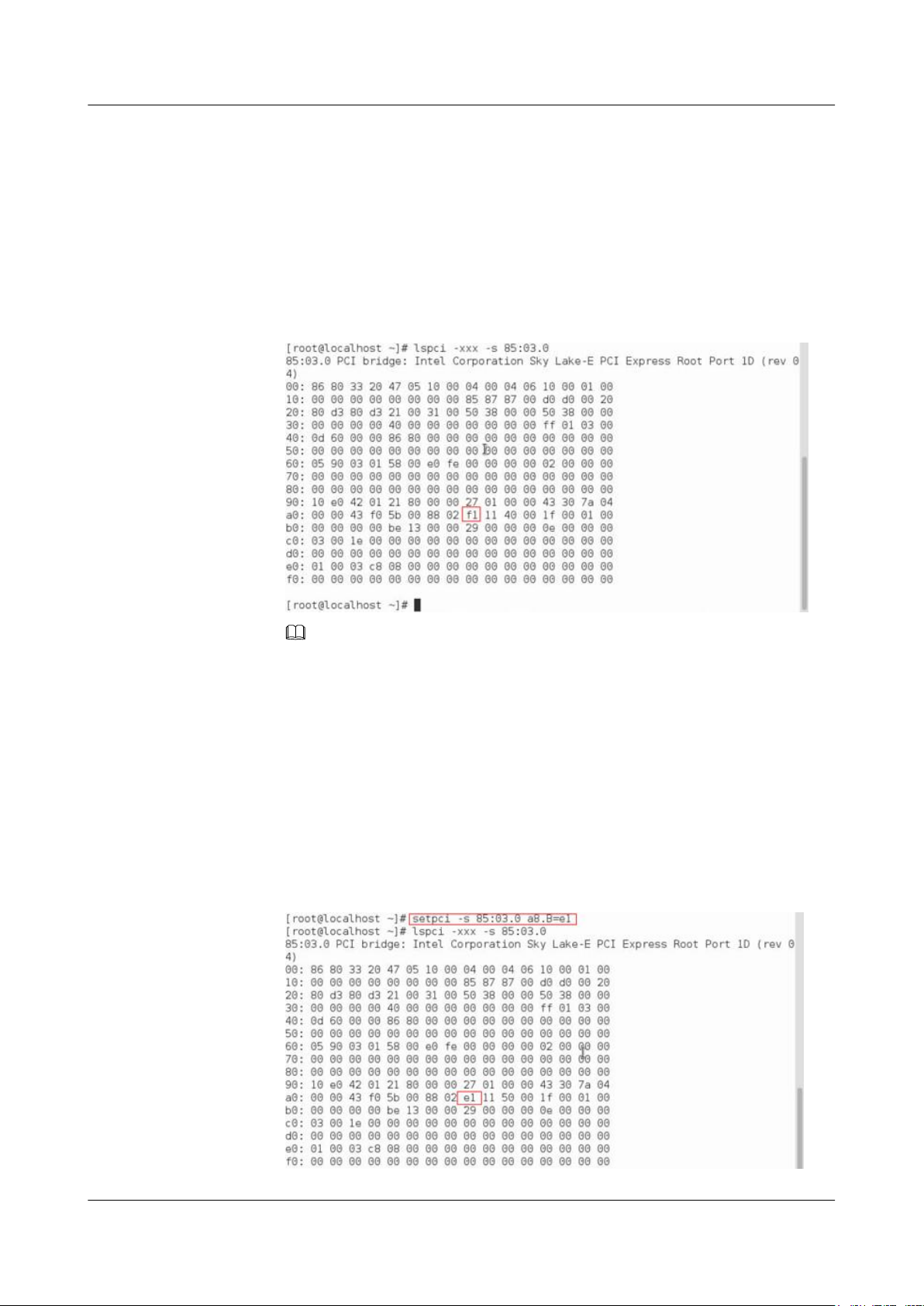
FusionServer Pro CH121 V5 Compute Node
User Guide
a. Run the following command to record the original a8 register value (the PCI data in
column 9 of row a0):
lspci -xxx -s <B/D/F>
<B/D/F>: indicates the root port (B/D/F) of the NVMe drive. For details about the
B/D/F information, see Table 3-2.
For example, if the drive No. is 2, run the following command:
lspci -xxx -s 85:03.0
Figure 3-45 Querying the original register value
3 Basic Operations
NOTE
If the default a8 register value is not f1, contact Huawei technical support.
b. Change the value of the a8 register to e1.
setpci -s <B/D/F> a8.B=e1
<B/D/F>: indicates the root port (B/D/F) of the NVMe drive. For details about the
B/D/F information, see Table 3-2.
c. Run the following command to check the modification result:
lspci -xxx -s <B/D/F>
<B/D/F>: indicates the root port (B/D/F) of the NVMe drive. For details about the
B/D/F information, see Table 3-2.
Figure 3-46 Querying the new register value of drive 2 (example)
Issue 06 (2019-08-10) Copyright © Huawei Technologies Co., Ltd. 60
Page 69
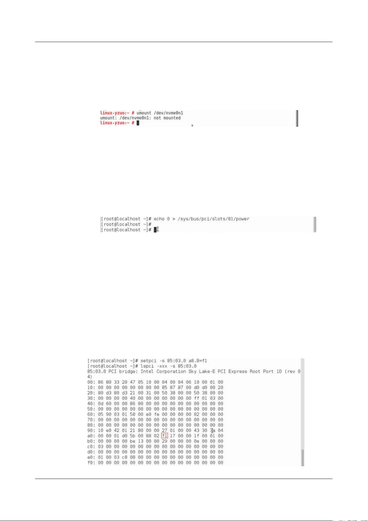
FusionServer Pro CH121 V5 Compute Node
User Guide
3. Stop accessing the NVMe drive.
Stop I/O operations on the NVMe drive to be removed and unmount any file systems
mounted to the drive. If the drive is used by the mdadm utility, you also need to set the
drive to the fail state.
Run the following command:
umount /dev/NVMe drive letter
4. Run the following command to safely remove the drive:
echo n > /sys/bus/pci/slots/Slot ID/power
– In the command, the value of n can be 0 or 1. The value 0 indicates unloading a
drive, and the value 1 indicates loading a drive. You can load a drive only before the
unloaded drive is removed.
– Slot ID: see Table 3-2.
For example, to orderly hot remove the NVMe drive in slot 2, run the following
command:
echo 0 > /sys/bus/pci/slots/81/power
3 Basic Operations
5. Observe the indicator status of the NVMe drive. If the green indicator is off and the
yellow indicator blinks at 0.5 Hz, remove the NVMe drive slowly.
For details about the drive indicator status, see NVMe SSD Indicators.
For details about how to manually remove an NVMe drive, see 3.13 Removing a SAS/
SATA Drive.
6. Place the removed component in an ESD bag.
Step 7 Run the following command to restore the value of the a8 register to the original value:
setpci -s <B/D/F> a8.B=Original a8 register value
<B/D/F>: indicates the root port (B/D/F) of the NVMe drive. For details about the B/D/F
information, see Table 3-2.
Figure 3-47 Resetting the value of the a8 register of drive 2 (example)
Issue 06 (2019-08-10) Copyright © Huawei Technologies Co., Ltd. 61
Page 70

FusionServer Pro CH121 V5 Compute Node
User Guide
NOTE
If the value of the register is not restored to the original one, the orderly hot insertion of the NVMe
drives may be abnormal.
Step 8 Install a drive filler.
NOTE
Perform this operation only when a drive is not installed immediately.
----End
3.16 Installing an NVMe Drive
l If the VMD function is enabled and the latest Intel RSTe driver is installed, the NVMe
drives support surprise hot swap.
– For details about how to enable the VMD function, see 12.9.1 Enabling VMD.
– Install the Intel RSTe driver. For details, see Huawei V5 Server RAID Controller
Card User Guide.
l If the VMD function is disabled, the NVMe drives support only orderly hot swap.
For details about how to disable the VMD function, see 12.9.2 Disabling VMD.
3 Basic Operations
Procedure (VMD Enabled)
NOTE
l Use the Intelligent Computing Compatibility Checker to obtain information about the operating
systems supported by the VMD function.
l Install the NVMe drives one by one. Install the next NVMe drive only after the previous one is
installed completely.
l If the OS is RHEL 7.3 and the VMD function is enabled, the OS kernel 3.10.0-514.el7.x86_64 must
be used for surprise hot swap of NVMe drives. Otherwise, the operating system may restart.
l If the VMD function is enabled, the RHEL 7.3 graphical installation interface cannot be accessed.
You can use a USB flash drive to access the RHEL 7.3 graphical installation interface. For details,
see Installing RHEL 7.3 on an NVMe SSD.
Step 1 Take the spare part out of its ESD bag.
Step 2 Determine the slot and position of the drive.
Issue 06 (2019-08-10) Copyright © Huawei Technologies Co., Ltd. 62
Page 71
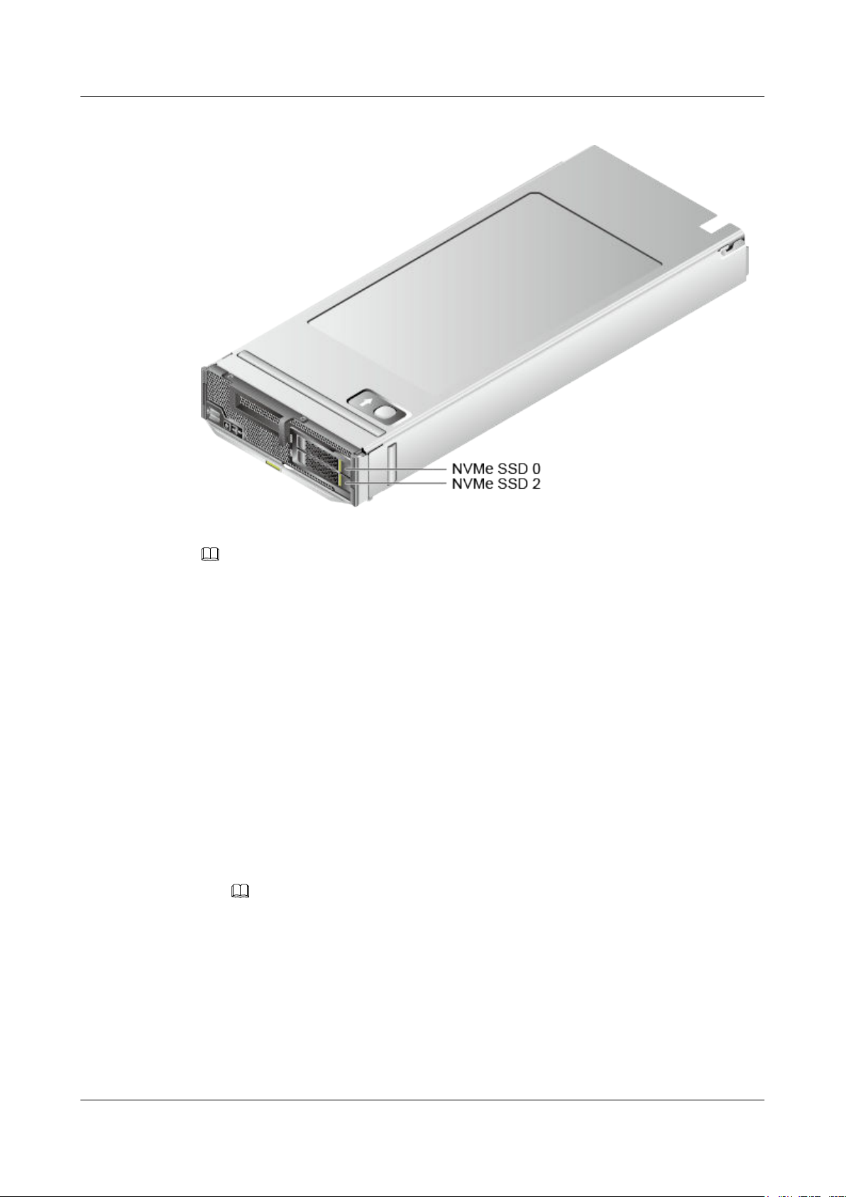
FusionServer Pro CH121 V5 Compute Node
User Guide
Figure 3-48 Positions of drives
3 Basic Operations
Step 3 Remove the drive filler.
NOTE
Perform this operation only when a drive filler is installed.
Step 4 Install the driver for NVMe drives.
l Install drivers for Intel series NVMe drives.
To ensure the stable running of NVMe drives, the following OSs are supported:
– The NVMe driver of the latest version must be installed for the Windows operating
system. For details about how to install the driver on the Windows OS, see Intel
NVMe Install Guide_330547-003.pdf obtained after the driver package is
decompressed.
– For Linux, you are advised to use Linux versions listed on the compatibility list.
Certain Linux OSs do not support the NVMe feature. You need to download the
NVMe driver from the official Intel website for such Linux OSs. For details about
how to install the driver on the Linux OS, see
Intel_Linux_NVMe_Guide_330602-002.pdf obtained after the driver package is
decompressed.
Driver download link: https://downloadcenter.intel.com/download/28718?v=t
NOTE
– Download the NVMe driver of the latest version.
– If no such driver is available, use the latest drive driver provided by the OS.
l Install drivers for Huawei series NVMe drives.
To ensure the stable running of NVMe drives, the following OSs are supported:
– The NVMe driver of the latest version must be installed for the Windows operating
system.
– Install the driver of the ES3000 V5 for a Linux OS. To enable hot swap, upgrade
the OS kernel.
Issue 06 (2019-08-10) Copyright © Huawei Technologies Co., Ltd. 63
Page 72

FusionServer Pro CH121 V5 Compute Node
User Guide
Driver download link: https://support.huawei.com/enterprise/en/servers/es3000-v5-
pid-22936194/software
For details about how to install the driver, see ES3000 V5 NVMe PCIe SSD User
Guide.
NOTE
– It is recommended that you install the latest driver.
– If Huawei NVMe driver is installed on a server using both Intel NVMe drives and Huawei
NVMe drives, the server cannot identify the Intel NVMe drives.
Step 5 Install NVMe drives.
NOTE
l The NVMe drive power-on duration varies with the NVMe drives.
l For details about how to install an OS on an NVMe drive, see Huawei Server OS Installation
Guide.
l Use the Intelligent Computing Compatibility Checker to obtain information about the OSs
supported by the NVMe drives with VMD enabled.
l Windows
a. Slowly insert the NVMe drive into the slot.
For details, see 3.14 Installing a SAS/SATA Drive.
b. Observe the drive indicators. If the green indicator is steady on and the yellow
indicator is off, the NVMe drive is detected and working properly.
For details, see NVMe SSD Indicators.
c. Check the status of the newly installed NVMe drive in the system.
n If the drive status is normal, no further action is required.
n If the newly installed NVMe drive cannot be identified, perform Step 5.d to
Step 5.e.
d. Go to Device Manager and scan for hardware changes.
e. Check the NVMe drive status on the OS.
l Linux
3 Basic Operations
a. Slowly insert the NVMe drive into the slot.
For details, see 3.14 Installing a SAS/SATA Drive.
b. Observe the drive indicators. If the green indicator is steady on and the yellow
indicator is off, the NVMe drive is detected and working properly.
For details, see NVMe SSD Indicators.
c. Check the status of the newly installed NVMe drive in the system.
Step 6 Log in to the iBMC WebUI, and check whether the new component is normal.
For details, see FusionServer Pro E9000 Server iBMC User Guide.
----End
Procedure (VMD Disabled)
Step 1 Take the spare part out of its ESD bag.
Step 2 Determine the slot and position of the drive.
Issue 06 (2019-08-10) Copyright © Huawei Technologies Co., Ltd. 64
Page 73
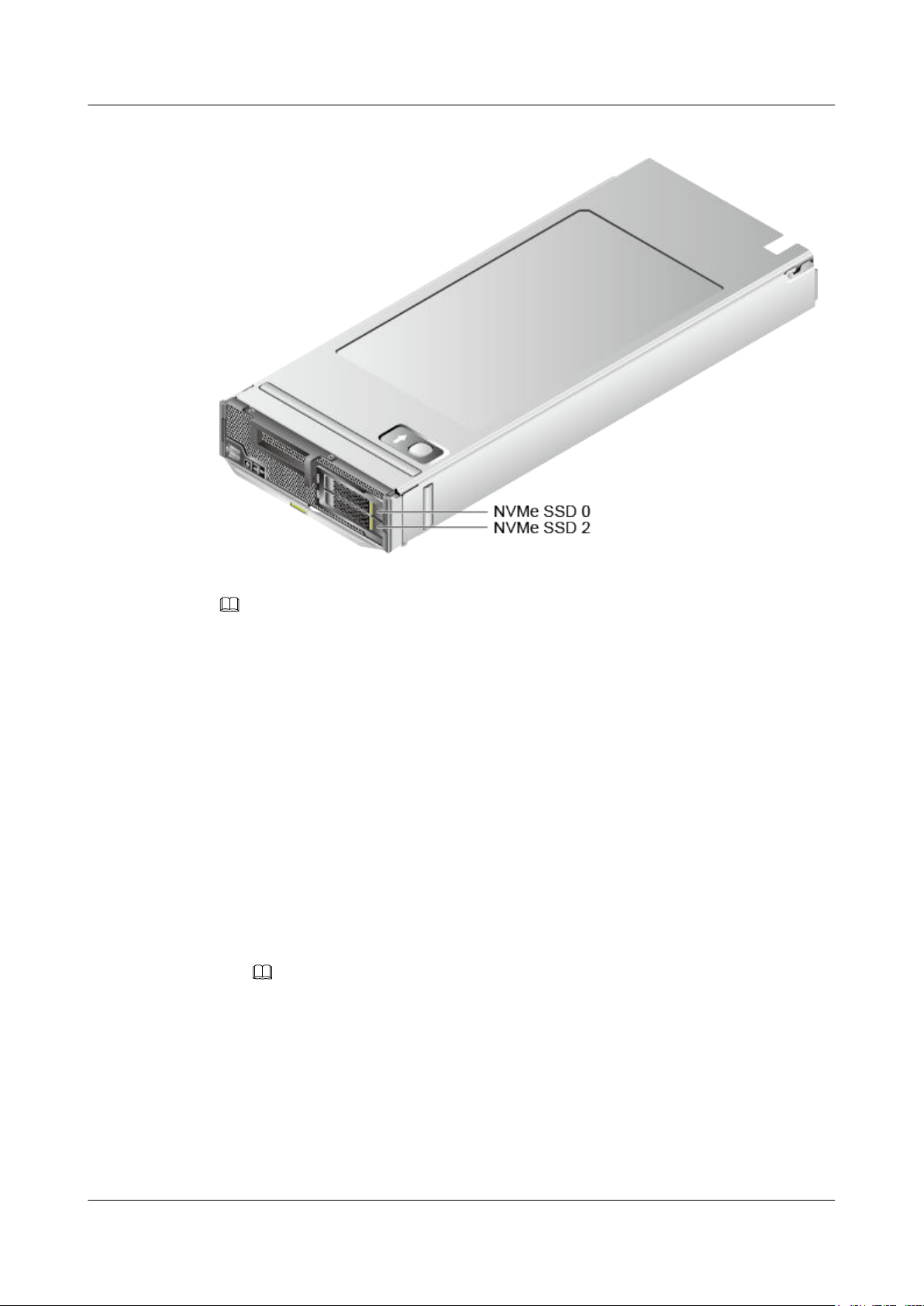
FusionServer Pro CH121 V5 Compute Node
User Guide
Figure 3-49 Positions of drives
3 Basic Operations
Step 3 Remove the drive filler.
NOTE
Perform this operation only when a drive filler is installed.
Step 4 Install the driver for NVMe drives.
l Install drivers for Intel series NVMe drives.
To ensure the stable running of NVMe drives, the following OSs are supported:
– The NVMe driver of the latest version must be installed for the Windows operating
system. For details about how to install the driver on the Windows OS, see Intel
NVMe Install Guide_330547-003.pdf obtained after the driver package is
decompressed.
– For Linux, you are advised to use Linux versions listed on the compatibility list.
Certain Linux OSs do not support the NVMe feature. You need to download the
NVMe driver from the official Intel website for such Linux OSs. For details about
how to install the driver on the Linux OS, see
Intel_Linux_NVMe_Guide_330602-002.pdf obtained after the driver package is
decompressed.
Driver download link: https://downloadcenter.intel.com/download/28718?v=t
NOTE
– Download the NVMe driver of the latest version.
– If no such driver is available, use the latest drive driver provided by the OS.
l Install drivers for Huawei series NVMe drives.
To ensure the stable running of NVMe drives, the following OSs are supported:
– The NVMe driver of the latest version must be installed for the Windows operating
system.
– Install the driver of the ES3000 V5 for a Linux OS. To enable hot swap, upgrade
the OS kernel.
Issue 06 (2019-08-10) Copyright © Huawei Technologies Co., Ltd. 65
Page 74

FusionServer Pro CH121 V5 Compute Node
User Guide
Driver download link: https://support.huawei.com/enterprise/en/servers/es3000-v5-
pid-22936194/software
For details about how to install the driver, see ES3000 V5 NVMe PCIe SSD User
Guide.
NOTE
– It is recommended that you install the latest driver.
– If Huawei NVMe driver is installed on a server using both Intel NVMe drives and Huawei
NVMe drives, the server cannot identify the Intel NVMe drives.
Step 5 Install NVMe drives.
NOTE
l When replacing an NVMe drive, install a new NVMe drive 30 seconds after the old one is removed.
l The NVMe drive power-on duration varies with the NVMe drives.
l Use the Intelligent Computing Compatibility Checker to obtain information about the OSs
supported by the NVMe drives with VMD disabled.
l Windows
a. Slowly insert the NVMe drive into the slot.
For details, see 3.14 Installing a SAS/SATA Drive.
b. Observe the drive indicators. If the green indicator is steady on and the yellow
indicator is off, the NVMe drive is detected and working properly.
For details, see NVMe SSD Indicators.
c. Check the status of the newly installed NVMe drive in the system.
n If the drive status is normal, no further action is required.
n If the newly installed NVMe drive cannot be identified, perform Step 5.d to
Step 5.e.
d. Go to Device Manager and scan for hardware changes.
e. Check the NVMe drive status on the OS.
l Linux
3 Basic Operations
a. Configure kernel parameters.
Log in to the OS, and open /boot/efi/EFI/redhat/grub.cfg (if the OS is installed in
UEFI mode) or /boot/grub2/grub.cfg (if the OS is installed in legacy mode).
n If RHEL 7.3 is installed in UEFI mode:
1) Run the cat /proc/cmdline command. If the command output does not
contain "pciehp.pciehp_force=1 pci=pcie_bus_perf", you need to
configure kernel parameters.
Figure 3-50 Opening the configuration file
2) Run the vi/boot/efi/EFI/redhat/grub.cfg command. In the command
output, find the sentence that is displayed after the cat/proc/cmdline
command is executed in Step 5.a.1), and add a space and then
Issue 06 (2019-08-10) Copyright © Huawei Technologies Co., Ltd. 66
Page 75
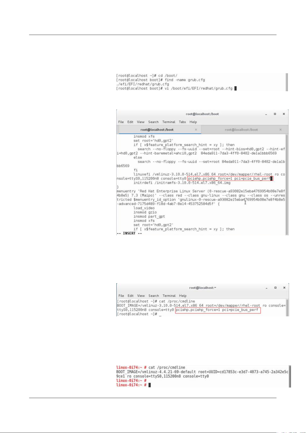
FusionServer Pro CH121 V5 Compute Node
User Guide
"pciehp.pciehp_force=1 pci=pcie_bus_perf" at the end of the sentence.
Do not add the content in a new line.
Figure 3-51 Configuring kernel parameters (1)
Figure 3-52 Configuring kernel parameters (2)
3 Basic Operations
3) Save the file and restart the compute node.
4) Run the cat /proc/cmdline command. If the command output contains
"pciehp.pciehp_force=1 pci=pcie_bus_perf", the kernel is configured
successfully.
Figure 3-53 Checking the configuration
n If SUSE 12.2 is installed in UEFI:
1) Run the cat /proc/cmdline command. If the command output does not
contain "pciehp.pciehp_force=1 pci=pcie_bus_perf", you need to
configure kernel parameters.
Figure 3-54 Opening the configuration file
Issue 06 (2019-08-10) Copyright © Huawei Technologies Co., Ltd. 67
Page 76
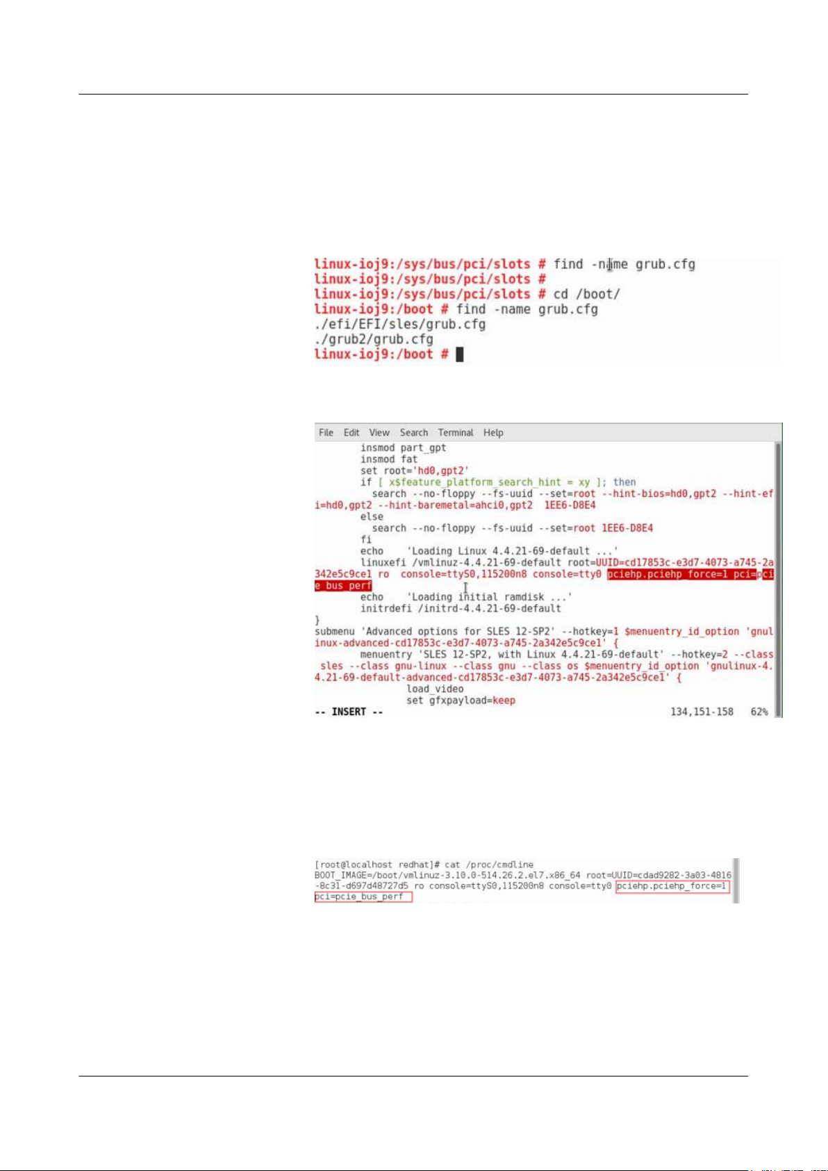
FusionServer Pro CH121 V5 Compute Node
User Guide
2) Run the vi /boot/efi/EFI/sles/grub.cfg command. In the command
output, find the sentence that is displayed after the cat/proc/cmdline
command is executed in Step 5.a.1), and add a space and then
"pciehp.pciehp_force=1 pci=pcie_bus_perf" at the end of the sentence.
Do not add the content in a new line.
Figure 3-55 Configuring kernel parameters (1)
Figure 3-56 Configuring kernel parameters (2)
3 Basic Operations
3) Save the file and restart the compute node.
4) Run the cat /proc/cmdline command. If the command output contains
"pciehp.pciehp_force=1 pci=pcie_bus_perf", the kernel is configured
successfully.
Figure 3-57 Checking the configuration
b. Upgrade the OS kernel.
n Example 1: RHEL 7.3
Upgrade the kernel of RHEL 7.3 to kernel-3.10.0-514.26.2.e17.x86_64 or
later to support orderly hot swap of NVMe drives.
1) Run the uname -r command to check the current kernel version.
Issue 06 (2019-08-10) Copyright © Huawei Technologies Co., Ltd. 68
Page 77
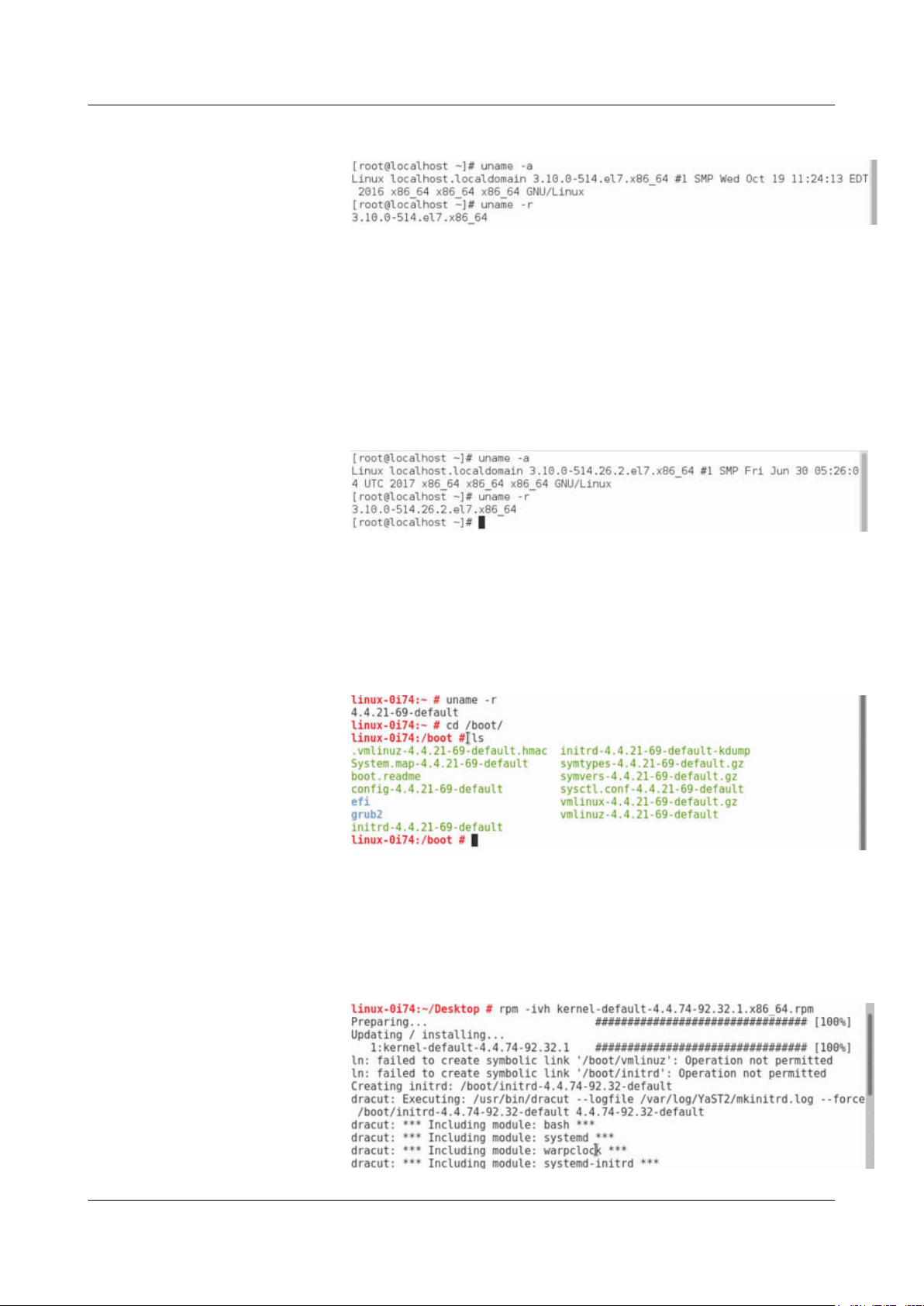
FusionServer Pro CH121 V5 Compute Node
User Guide
Figure 3-58 Kernel version
2) Log in to the official Red Hat website to download the kernel upgrade
package (kernel-3.10.0-514.26.2.e17.x86_64.rpm for example).
3) Run the rpm -ivh kernel-3.10.0-514.26.2.e17.x86_64.rpm command to
upload the upgrade package to the OS for installation.
4) Restart the OS after the installation is complete.
5) Run the uname -r command. If 3.10.0-514.26.2.el7.x86_64 is displayed,
the kernel is upgraded successfully.
Figure 3-59 Checking the kernel version
3 Basic Operations
n Example 2: SUSE 12.2
Upgrade the kernel of SUSE 12.2 to kernel-default-4.4.74-92.32.1.x86_64 or
later to support orderly hot swap of NVMe drives.
1) Run the uname -r command to check the current kernel version.
Figure 3-60 Kernel version
2) Log in to the official SUSE website to download the kernel upgrade
package (kernel-3.10.0-514.26.2.e17.x86_64 for example).
3) Run the rpm -ivh kernel-default-4.4.74-92.32.1.x86_64.rpm command
to upload the upgrade package to the OS for installation.
Figure 3-61 Installing the upgrade package
Issue 06 (2019-08-10) Copyright © Huawei Technologies Co., Ltd. 69
Page 78

FusionServer Pro CH121 V5 Compute Node
User Guide
4) Restart the OS after the installation is complete.
5) Run the uname -r command to check the kernel version.
If it is still the original kernel version, change the version in the grub.cfg
file.
c. Slowly insert the NVMe drive into the slot.
For details, see 3.14 Installing a SAS/SATA Drive.
d. Observe the drive indicators. If the green indicator is steady on and the yellow
indicator is off, the NVMe drive is detected and working properly.
For details, see NVMe SSD Indicators.
e. Check the status of the newly installed NVMe drive in the system.
Step 6 Log in to the iBMC WebUI, and check whether the new component is normal.
For details, see FusionServer Pro E9000 Server iBMC User Guide.
Step 7 Determine whether to install the OS on the NVMe drive.
l If yes, go to Step 8.
l If no, no further action is required.
3 Basic Operations
Step 8 Install an OS on the NVMe drive.
NOTE
l When installing a supported OS on an NVMe drive, load the NVMe driver for the system to enable
the NVMe drives to be identified by the OS. Then, proceed with the OS installation.
l Only the UEFI mode supports OS installation on an NVMe drive.
1. Set the UEFI mode.
a. Press Del upon server startup to access the BIOS.
b. Open the boot configuration screen and set Boot Type to UEFI Boot Type.
c. Press F10 to save the setting and exit.
2. Install Windows Server 2012 (example) on an NVMe drive.
a. Install the OS.
If the NVMe drive cannot be detected when the system scans for the target
installation device, mount the NVMe driver file by using the virtual DVD drive or
floppy disk drive (FDD) on the server management WebUI.
b. Download the NVMe driver for Windows Server 2012, and create an ISO or IMG
file.
c. Load the NVMe driver on the installation UI. After the NVMe drive is detected,
proceed with the OS installation.
----End
Issue 06 (2019-08-10) Copyright © Huawei Technologies Co., Ltd. 70
Page 79

FusionServer Pro CH121 V5 Compute Node
User Guide
4 Installation and Configuration
4.1 Installation Environment Requirements
4.2 Hardware Installation
4.3 Initial Configuration
4 Installation and Configuration
4.1 Installation Environment Requirements
4.1.1 Space and Airflow Requirements
To allow for servicing and adequate airflow, observe the following space and airflow
requirements:
l Install the server in an access-restricted area.
l Keep the area in which the server is located clean and tidy.
l To facilitate heat dissipation and maintenance, keep a clearance of 800 mm (31.50 in.)
between walls and the front and rear doors of the cabinet.
l Do not block the air intake vents. Otherwise, air intaking and heat dissipation will be
affected.
l The air conditioning system in the equipment room provides enough wind to ensure
proper heat dissipation of all components.
4.1.2 Temperature and Humidity Requirements
To ensure continued safe and reliable equipment operation, install or position the system in a
well-ventilated, climate-controlled environment.
l Use temperature control devices all year long in any climates.
l In dry and humid areas, maintain ambient humidity within range with humidifiers and
dehumidifiers respectively.
Issue 06 (2019-08-10) Copyright © Huawei Technologies Co., Ltd. 71
Page 80
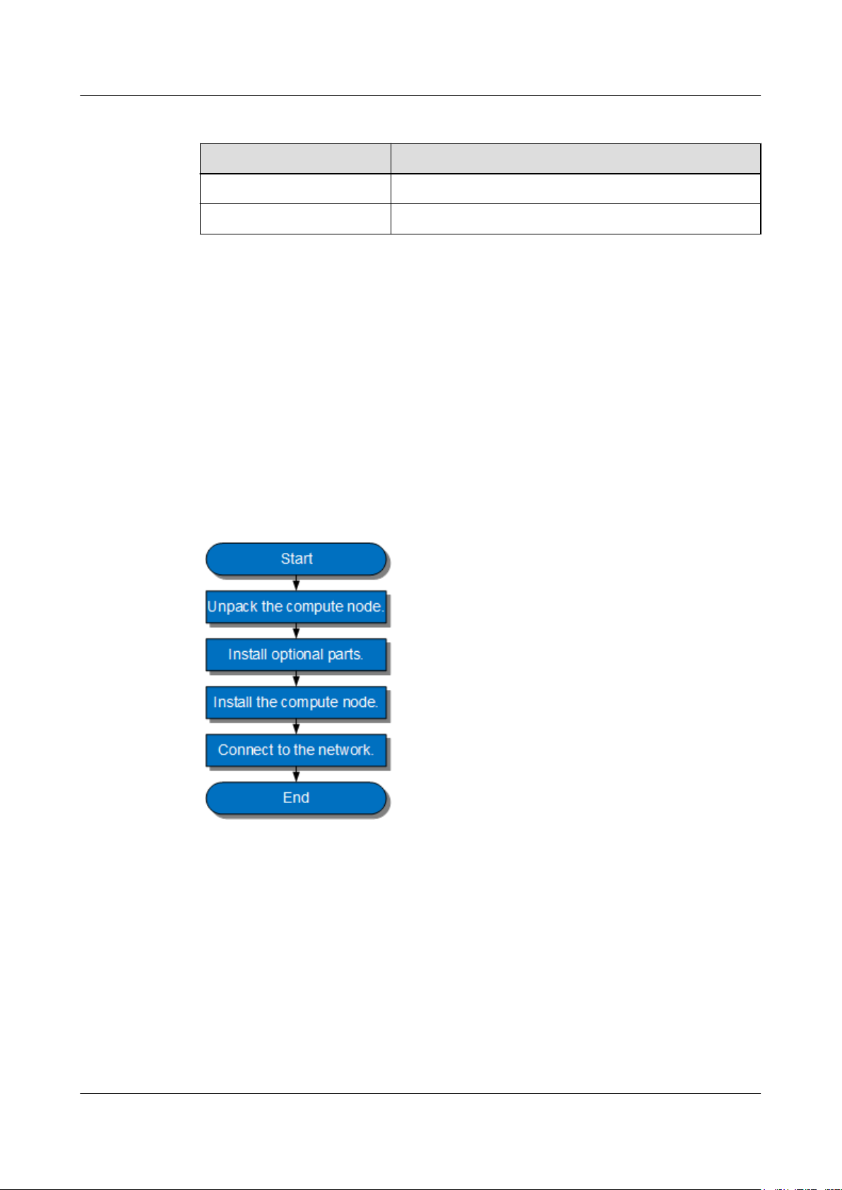
FusionServer Pro CH121 V5 Compute Node
User Guide
Table 4-1 Temperature and humidity requirements in the equipment room
Item Description
Temperature 5ºC to 35ºC (41ºF to 95ºF)
Humidity 8% RH to 90% RH (non-condensing)
4.1.3 Cabinet Requirements
l A general 19-inch cabinet with a depth of more than 1000 mm (39.37 in.) which
complies with the International Electrotechnical Commission 297 (IEC 297) standard.
l Air filters installed on cabinet doors.
4.2 Hardware Installation
4 Installation and Configuration
4.2.1 Installation Overview
Figure 4-1 Installation process
l Properly ground the server before installation to avoid damage to electronic components
from electrostatic discharge. Improper grounding may cause electrostatic discharge.
For details about how to prevent electrostatic discharge, see 10.1 Preventing
Electrostatic Discharge .
l Before installing multiple components, read the installation instructions for all the
components and identify similar actions to simply the installation process.
Use the Intelligent Computing Compatibility Checker to obtain information about the
components supported.
Issue 06 (2019-08-10) Copyright © Huawei Technologies Co., Ltd. 72
Page 81
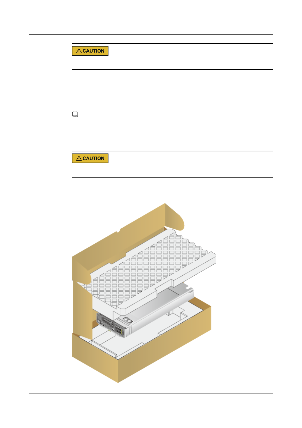
FusionServer Pro CH121 V5 Compute Node
User Guide
Wait until overheating devices have cooled down before touching them to avoid injury.
4.2.2 Unpacking the Compute Node
Procedure
Step 1 Check whether the packing case and seals are in good conditions.
NOTE
If the packing case is soaked or deformed, or the seals or pressure-sensitive adhesive tapes are not intact,
fill in the Cargo Problem Feedback Form.
Step 2 Use a box cutter to open the packing case.
Exercise caution with the box cutter to avoid injury to your hands or damage to devices.
4 Installation and Configuration
Step 3 Unpack the packing case.
Figure 4-2 Unpacking the packing case
Issue 06 (2019-08-10) Copyright © Huawei Technologies Co., Ltd. 73
Page 82
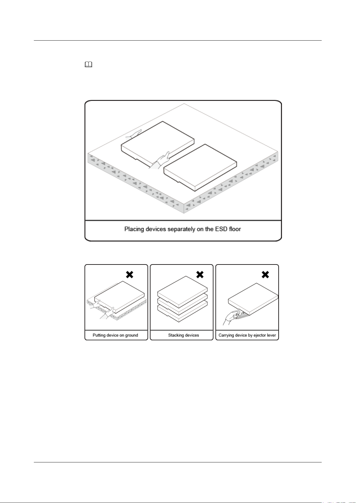
FusionServer Pro CH121 V5 Compute Node
User Guide
Step 4 Take the compute nodes out of the ESD bags and place them separately on the ESD floor.
NOTE
Take out the compute node only before you install it immediately.
Figure 4-3 Proper operation
4 Installation and Configuration
Figure 4-4 Improper operations
----End
4.2.3 Installing Optional Parts
Before installing and configuring a compute node, you need to install all optional parts
required, such as extra CPUs, drives, and mezzanine cards.
Procedure
Step 1 Install the optional parts for the CH121 V5.
For details, see 5.2 Optional Parts.
----End
Issue 06 (2019-08-10) Copyright © Huawei Technologies Co., Ltd. 74
Page 83
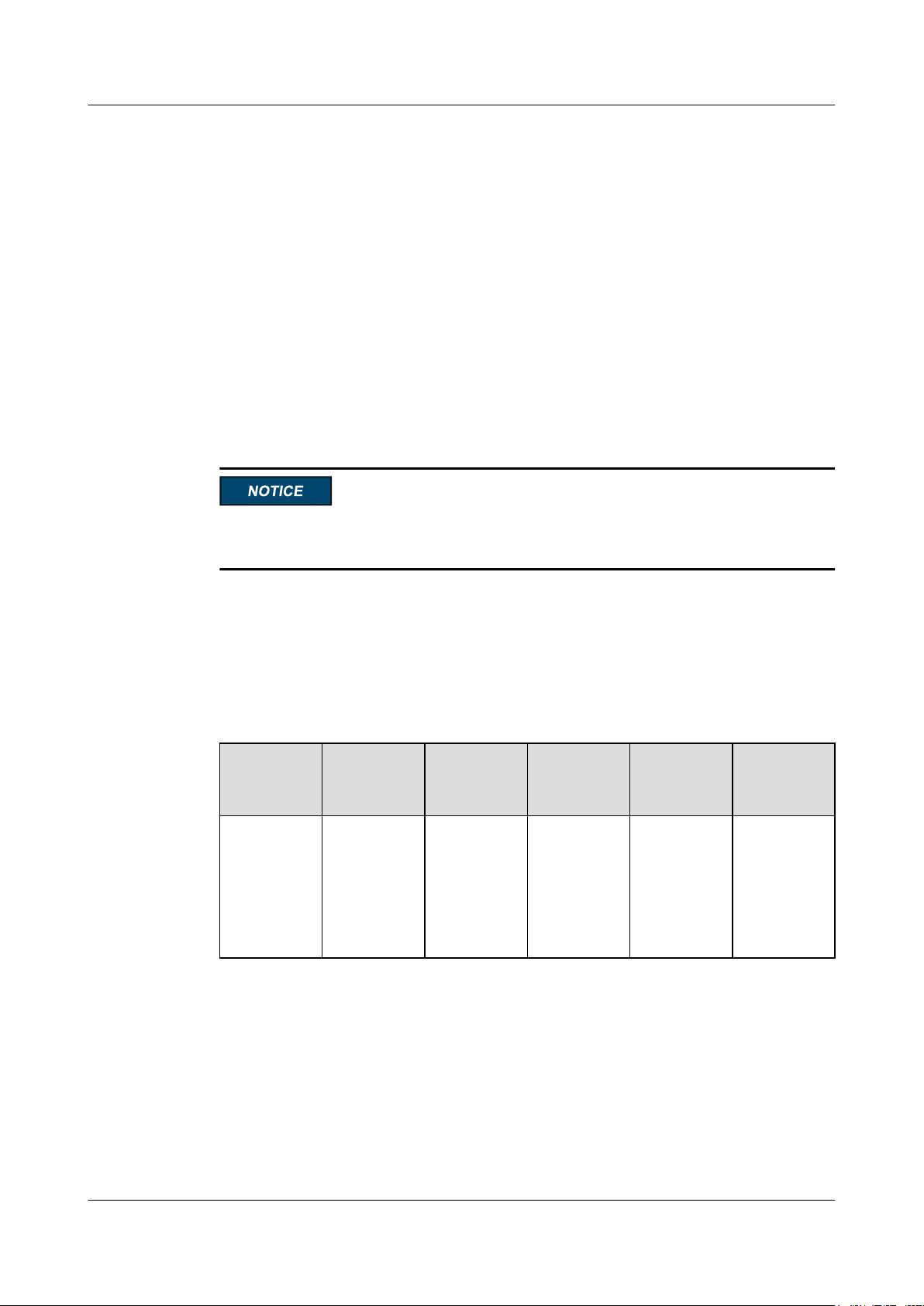
FusionServer Pro CH121 V5 Compute Node
User Guide
4.2.4 Installing the Compute Node
Procedure
Step 1 Install the CH121 V5.
For details, see 3.4 Installing a CH121 V5.
----End
4.2.5 Connecting to Network
To connect the E9000 to the network, install switch modules for signal management between
the compute node and external network.
For details about the switch module, see the user guide of the switch module you use.
4 Installation and Configuration
The NIC configured for the compute node must match the switch module configured for the
chassis. Otherwise, the network connection may fail.
4.3 Initial Configuration
4.3.1 Default Information
Table 4-2 Default information
User Name
AdministratorAn iBMC
User
Descriptio
n
user
NOTE
iBMC does
not have a
default IP
address.
Default
Password
Admin@9000Administrati
User Type User Status Login
ve User
Method
Enabled Remote and
local login
Issue 06 (2019-08-10) Copyright © Huawei Technologies Co., Ltd. 75
Page 84

FusionServer Pro CH121 V5 Compute Node
User Guide
4 Installation and Configuration
User Name User
Descriptio
n
- A user that
logs in to UBoot over a
serial port.
No user
name is
used. This
applies to all
compute
nodes.
- A user that
logs in to the
basic input/
output
(BIOS)
Setup menu
over a serial
port or
KVM (
Keyboard
Video and
Mouse).
No user
name is
used. This
applies to all
compute
nodes.
Default
User Type User Status Login
Password
Admin@9000Administrati
ve User
Admin@9000Administrati
ve User
Method
Enabled Local login
Enabled Remote and
local login
AdministratorA user of the
Secure Shell
Admin@9000Administrati
ve User
Enabled Remote and
local login
Daemon
(SSHD).
The SSH
protocol
allows a user
to remotely
log in to the
host
execution
program,
implementin
g secure
management
for the host.
Issue 06 (2019-08-10) Copyright © Huawei Technologies Co., Ltd. 76
Page 85
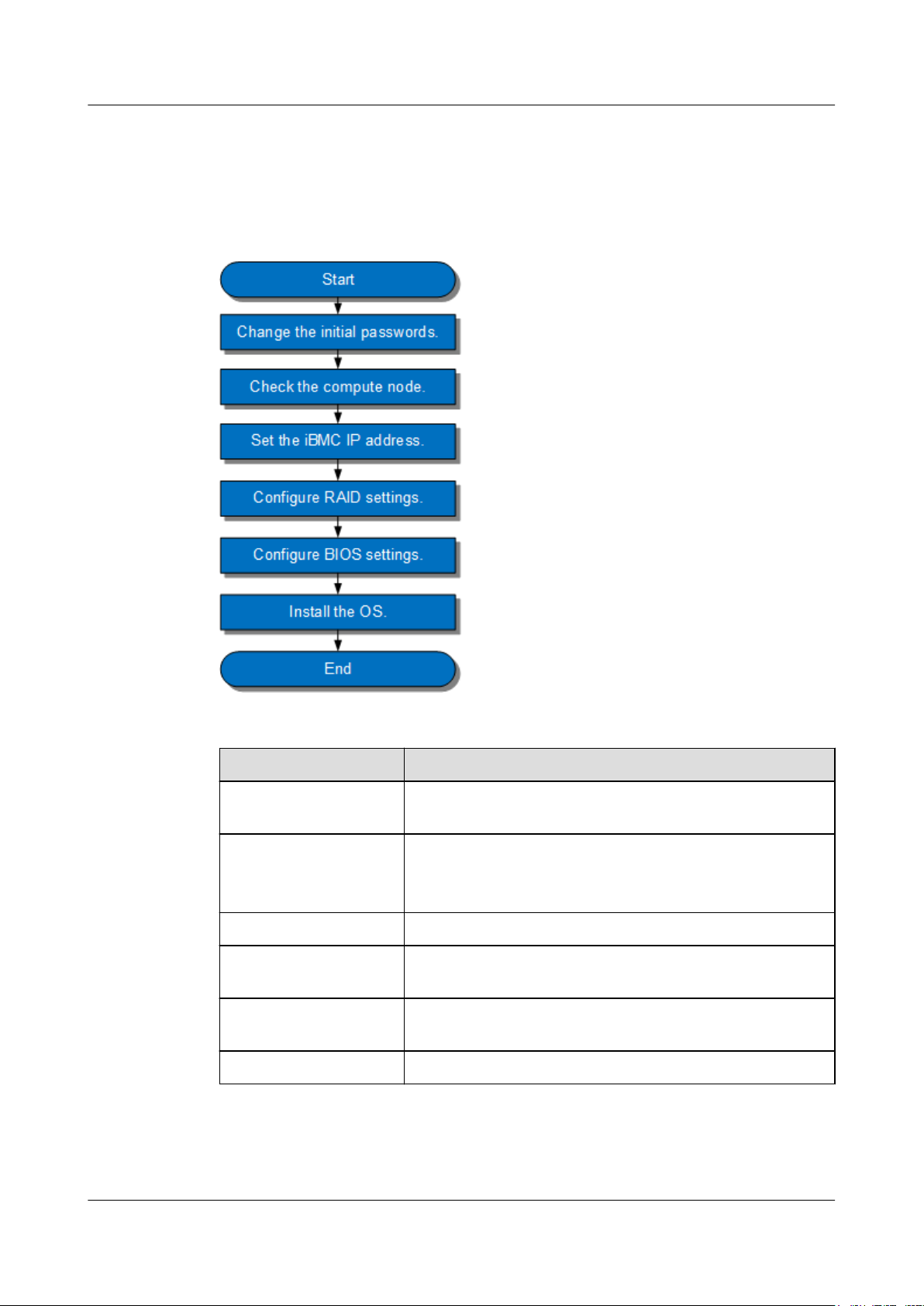
FusionServer Pro CH121 V5 Compute Node
User Guide
4.3.2 Configuration Overview
Configuration Process
Figure 4-5 Initial configuration process
4 Installation and Configuration
Table 4-3 Process description
Step
Change the initial
passwords
Check the compute node
Set the iBMC IP address Set an iBMC IP address for the compute node
Configure RAID Configure the corresponding RAID array based on service
Configure the BIOS Configure the BIOS of the compute node, including the boot
Install the OS Install an OS for the compute node
Description
Initial password of the default iBMC user
l Ensure that the compute node version meets site
requirements.
l Ensure that no alarm is generated for the compute node.
scenarios.
mode, NIC PXE function, and BIOS password
Issue 06 (2019-08-10) Copyright © Huawei Technologies Co., Ltd. 77
Page 86

FusionServer Pro CH121 V5 Compute Node
User Guide
4 Installation and Configuration
Documents
l Configure the iBMC. The configuration method varies depending on the iBMC version.
For details, see FusionServer Pro E9000 Server iBMC User Guide.
l Configure RAID settings. For details, see Huawei V5 Server RAID Controller Card
User Guide.
l Configure BIOS settings. For details, see Huawei Server Purley Platform BIOS
Parameter Reference.
l Install the operating system. For details, see Huawei Server OS Installation Guide.
l Handle alarms. For details, see FusionServer Pro E9000 Server V100R001 HMM
Alarm Handling.
l Rectify faults. For details, see Huawei Servers Troubleshooting.
4.3.3 Changing Initial Passwords
4.3.3.1 Changing the Initial Password of the Default iBMC User
Scenarios
This section describes how to change the initial password of the default iBMC user on the
iBMC WebUI.
You can change the initial password of the default iBMC user on:
l MM910 WebUI
For details, see MM910 Management Module V100R001 User Guide.
l MM910 CLI
For details, see MM910 Management Module V100R001 Command Reference.
l iBMC WebUI
For details, see FusionServer Pro E9000 Server iBMC User Guide.
l iBMC CLI
For details, see FusionServer Pro E9000 Server iBMC User Guide.
NOTE
l The default user name of the iBMC is Administrator, and the default password is Admin@9000.
l For security purposes, change the initial password upon the first login and change the password
periodically.
l You are advised to use a password that meets complexity requirements or to enable the password
complexity check function.
l The password complexity check function is enabled by default.
Procedure
Step 1 Log in to the MM910 WebUI.
For details, see 12.3 Logging In to the MM910 WebUI.
Step 2 On the HMM Web page, choose System Management.
The System Management page is displayed.
Issue 06 (2019-08-10) Copyright © Huawei Technologies Co., Ltd. 78
Page 87
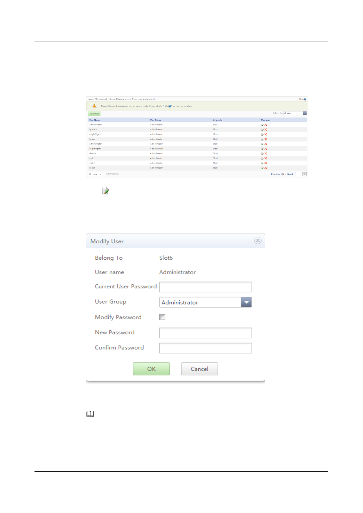
FusionServer Pro CH121 V5 Compute Node
User Guide
Step 3 In the navigation tree, choose Account Management > Node User Management.
The Node User Management page is displayed.
Figure 4-6 Node User Management page
Step 4 Click on the right of the compute node in the specific slot.
4 Installation and Configuration
The Modify User dialog box is displayed.
Figure 4-7 Modify User dialog box
Step 5 Enter the current password, select Modify Password, and enter a new password in New
Password and Confirm Password.
NOTE
l The default user name of the iBMC is Administrator, and the default password is Admin@9000.
l This user is the default iBMC user, who belongs to the administrator group. This user has permission
to access all iBMC resources and perform all operations.
Step 6 Click OK.
Issue 06 (2019-08-10) Copyright © Huawei Technologies Co., Ltd. 79
Page 88
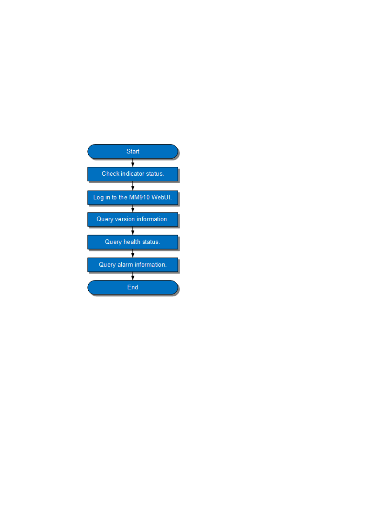
FusionServer Pro CH121 V5 Compute Node
User Guide
The initial password of the iBMC is changed.
----End
4.3.4 Checking the Compute Node
Process
Check the compute node by performing the following operations:
Figure 4-8 Check process
4 Installation and Configuration
Procedure
Step 1 Check the indicators on the panels and ensure that the device is working properly.
For details, see 2.1.2 Indicators and Buttons.
Step 2 Log in to the MM910 WebUI.
For details, see 12.3 Logging In to the MM910 WebUI.
Step 3 Query version information.
1. On the menu bar, choose Chassis Information.
2. Click the compute node in the specific slot and choose Version Information to query
the version information of the compute node.
Issue 06 (2019-08-10) Copyright © Huawei Technologies Co., Ltd. 80
Page 89
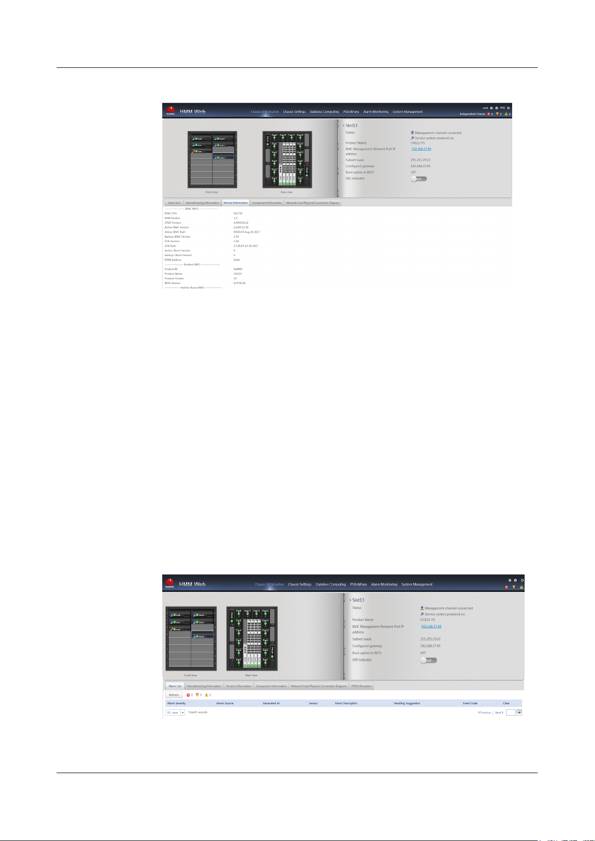
FusionServer Pro CH121 V5 Compute Node
User Guide
Figure 4-9 Querying version information
Pay attention to the following information:
– CPLD Version: CPLD version of the compute node
– Active iBMC Version: version of the iBMC in the active work space of the
compute node
– Backup iBMC Version: version of the iBMC in the standby work space of the
compute node
3. Check whether the versions meet site requirements.
– If yes, go to Step 4.
– If no, go to Step 3.4.
4. Upgrade the iBMC, BIOS, or CPLD.
For details, see E9000 Server V100R001 Upgrade Guide.
4 Installation and Configuration
Step 4 Query health status.
Step 5 Query alarm information.
1. Click the compute node in the specific slot and choose Alarm List.
Figure 4-10 Querying alarm information
2. Check whether any alarm is generated.
– If yes, handle the alarms.
Issue 06 (2019-08-10) Copyright © Huawei Technologies Co., Ltd. 81
Page 90

FusionServer Pro CH121 V5 Compute Node
User Guide
For details, see FusionServer Pro E9000 Server V100R001 HMM Alarm
Handling.
– If no, no further action is required.
----End
4.3.5 Setting the iBMC IP Address
Scenarios
This section describes how to set the iBMC IP address on the MM910 WebUI.
You can set the iBMC IP address on:
l BIOS
l MM910 WebUI
For details, see MM910 Management Module V100R001 User Guide.
l MM910 CLI
4 Installation and Configuration
For details, see MM910 Management Module V100R001 Command Reference.
l iBMC WebUI
For details, see FusionServer Pro E9000 Server iBMC User Guide.
l iBMC CLI
Run the following command: ipmcset -d ipaddr
For details, see FusionServer Pro E9000 Server iBMC User Guide.
Procedure (on the MM910 WebUI)
Step 1 Log in to the MM910 WebUI.
For details, see 12.3 Logging In to the MM910 WebUI.
Step 2 Set the iBMC IP address
To avoid conflicts with the network segment of the chassis management plane, the iBMC IP
address of the compute node cannot be configured in the 172.31.xx.xx network segment. If
you need to configure the iBMC IP address, change the IP addresses of the HMM and
compute node in the network segment of the chassis management plane. For details, see
section "Querying and Setting a Network Segment for the Chassis Management Plane
(subnet)" in MM910 Management Module V100R001 Command Reference.
1. On the HMM Web page, choose Chassis Settings.
The Chassis Settings page is displayed.
2. In the navigation tree, choose Network Settings > Node.
Issue 06 (2019-08-10) Copyright © Huawei Technologies Co., Ltd. 82
Page 91

FusionServer Pro CH121 V5 Compute Node
User Guide
Figure 4-11 Setting an IP address for the management network port
3. Click Edit.
Edit the iBMC IP address of the compute node in a specific slot.
4. Click Save.
The iBMC IP address is set.
----End
4 Installation and Configuration
4.3.6 Configuring RAID
The CH121 V5 supports multiple types of RAID controller cards.
l Use Intelligent Computing Compatibility Checker to obtain information about the
compatible RAID controller cards.
l The configuration method varies depending on the RAID controller card model. For
details, see Huawei V5 Server RAID Controller Card User Guide.
4.3.7 Configuring the BIOS
Scenarios
This section describes how to configure the BIOS of the compute node.
To configure the BIOS, perform the following operations:
l Set the system boot sequence
l Set PXE for a NIC
l Set the BIOS password
l Select a language
For details about other configurations, see Huawei Server Purley Platform BIOS
Parameter Reference.
Issue 06 (2019-08-10) Copyright © Huawei Technologies Co., Ltd. 83
Page 92
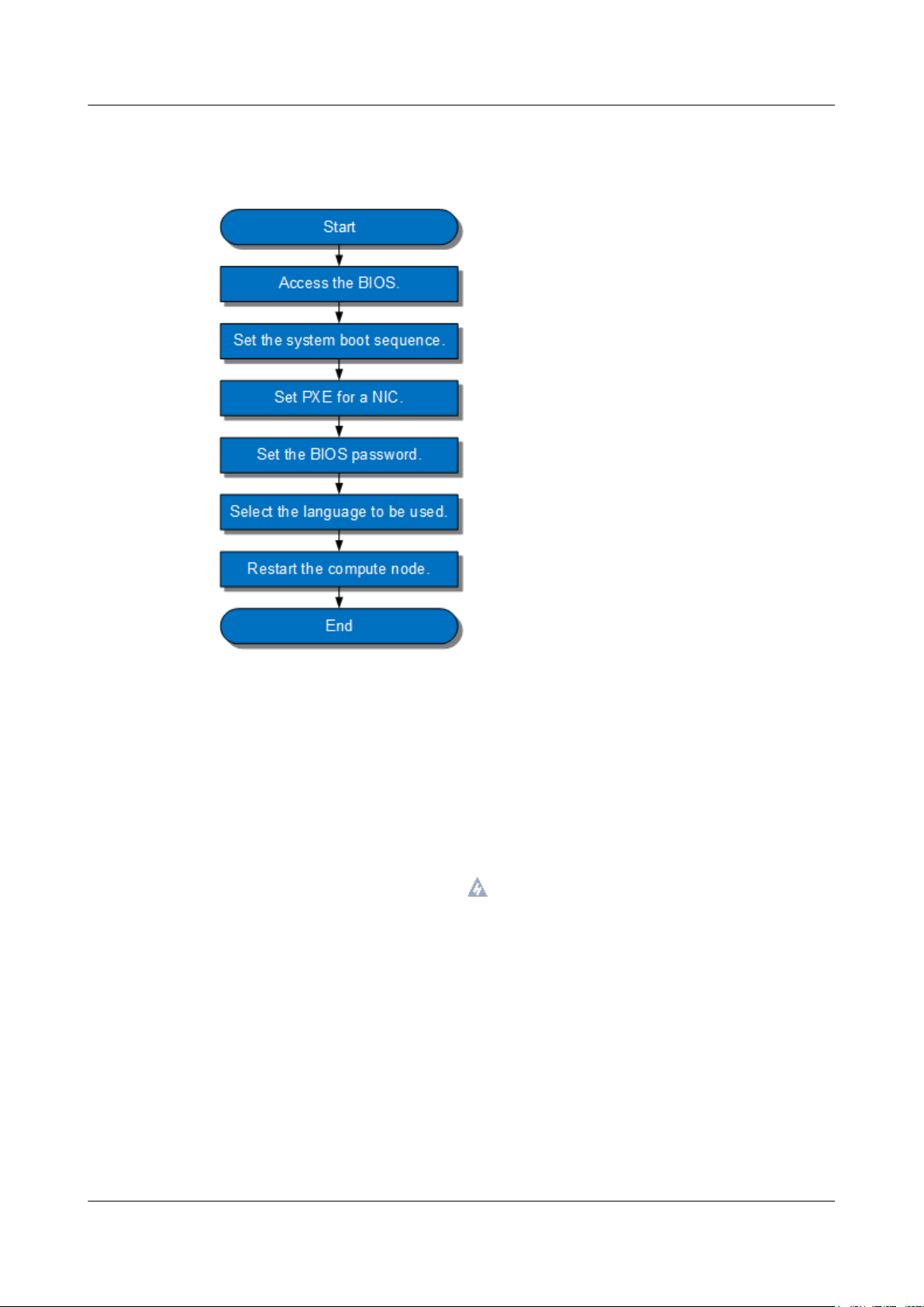
FusionServer Pro CH121 V5 Compute Node
User Guide
Process
Figure 4-12 Process for configuring the BIOS
4 Installation and Configuration
4.3.7.1 Entering the BIOS
4.3.7.1.1 Entering the BIOS (Skylake)
Procedure
Step 1 Log in to the desktop of the compute node.
For details, see 12.7 Logging In to the Desktop of a Server.
Step 2 On the Remote Virtual Console, click on the menu bar.
Step 3 Select Reset or Forced System Reset.
"Are you sure to perform this operation?" is displayed.
Step 4 Click Yes.
The compute node is restarted.
Step 5 During the restart, press Delete or F4 when the information shown in Figure 4-13 is
displayed.
Issue 06 (2019-08-10) Copyright © Huawei Technologies Co., Ltd. 84
Page 93
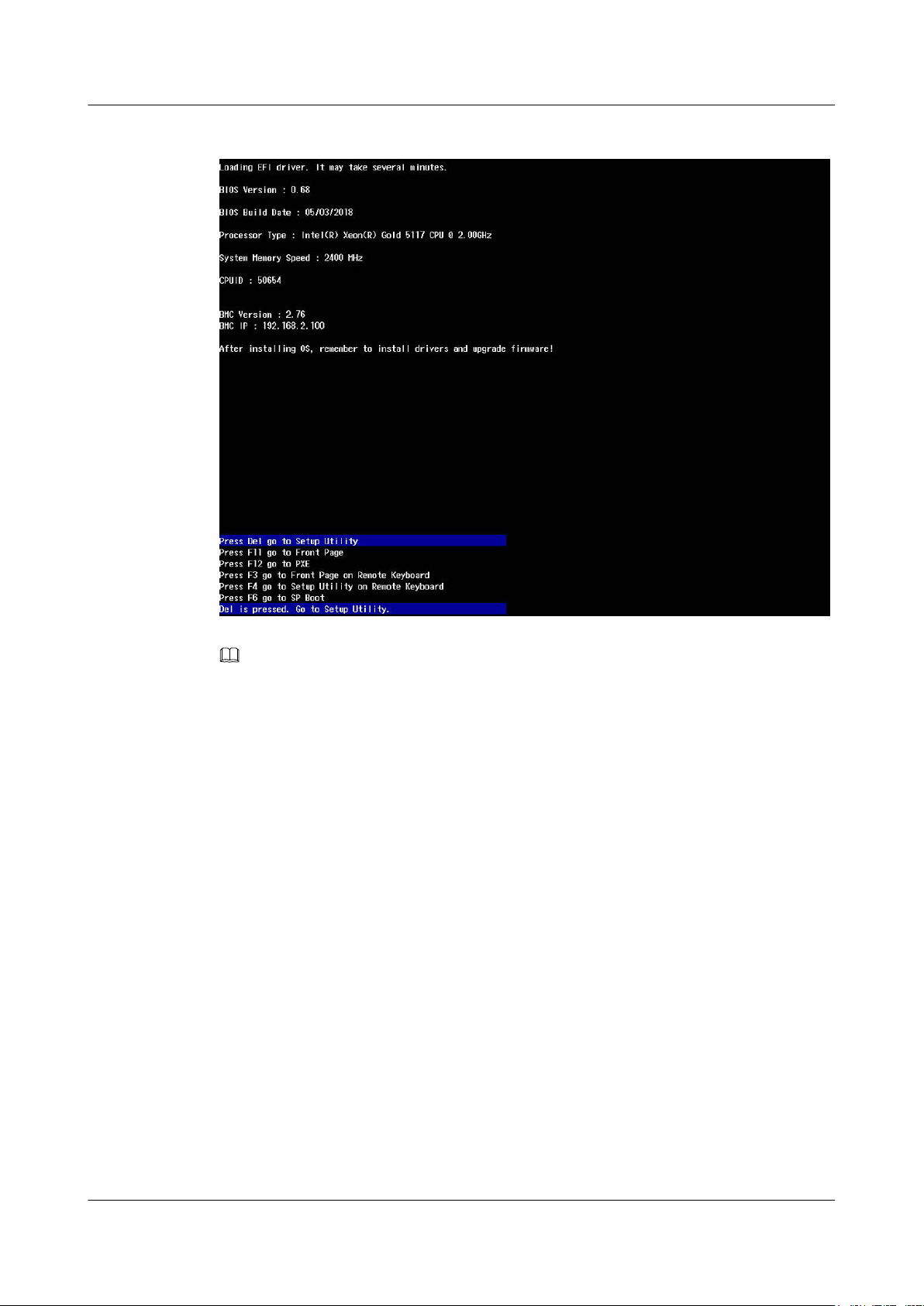
FusionServer Pro CH121 V5 Compute Node
User Guide
Figure 4-13 BIOS startup screen
4 Installation and Configuration
NOTE
l To go to the BIOS front page, press F11 or F3.
l To boot from the network, press F12. Enter the password in the displayed dialog box.
l To access the Smart Provisioning GUI, press F6.
The screen for entering the BIOS password is displayed.
Issue 06 (2019-08-10) Copyright © Huawei Technologies Co., Ltd. 85
Page 94
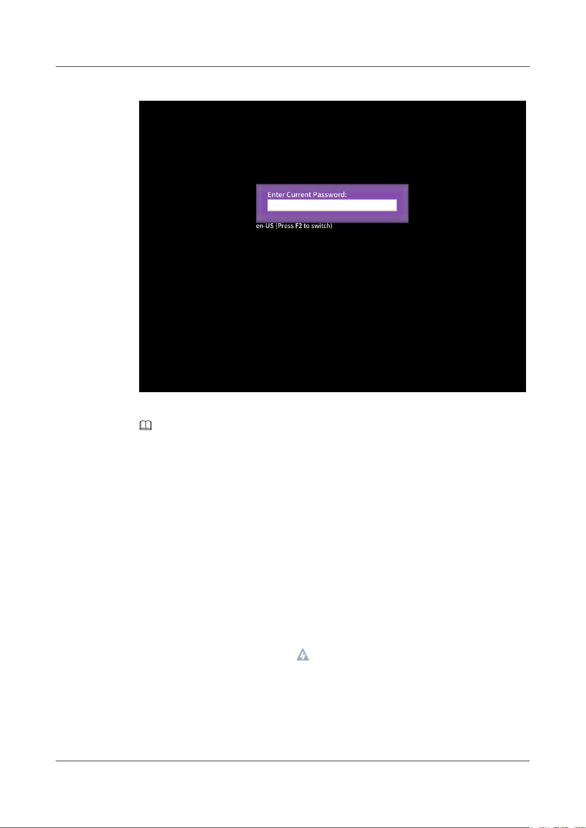
FusionServer Pro CH121 V5 Compute Node
User Guide
Figure 4-14 Entering the BIOS password
4 Installation and Configuration
Step 6 Enter the BIOS password.
NOTE
l The default BIOS password is Admin@9000.
l Press F2 to alternate between the English (US), French, and Japanese keyboards.
l For security purposes, change the administrator password periodically.
l The system will be locked if an incorrect password is entered three consecutive times. You can
restart the compute node to unlock it.
The Main screen of the Setup Utility program is displayed.
----End
4.3.7.1.2 Entering the BIOS (Cascade Lake)
Procedure
Step 1 Log in to the desktop of the compute node.
For details, see 12.7 Logging In to the Desktop of a Server.
Step 2 On the Remote Virtual Console, click
Step 3 Select Reset or Forced System Reset.
on the menu bar.
"Are you sure to perform this operation?" is displayed.
Step 4 Click Yes.
The compute node is restarted.
Issue 06 (2019-08-10) Copyright © Huawei Technologies Co., Ltd. 86
Page 95
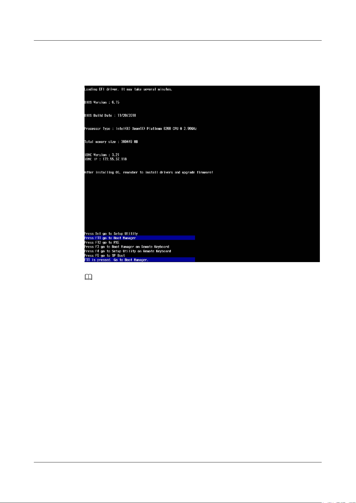
FusionServer Pro CH121 V5 Compute Node
User Guide
Step 5 During the restart, press Delete or F4 when the information shown in Figure 4-15 is
displayed.
Figure 4-15 BIOS startup screen
4 Installation and Configuration
NOTE
l To go to the Boot Manager screen, press F11 pr F3.
l To boot from the network, press F12.
l To access the Smart Provisioning GUI, press F6.
The screen for entering the BIOS password is displayed.
Issue 06 (2019-08-10) Copyright © Huawei Technologies Co., Ltd. 87
Page 96
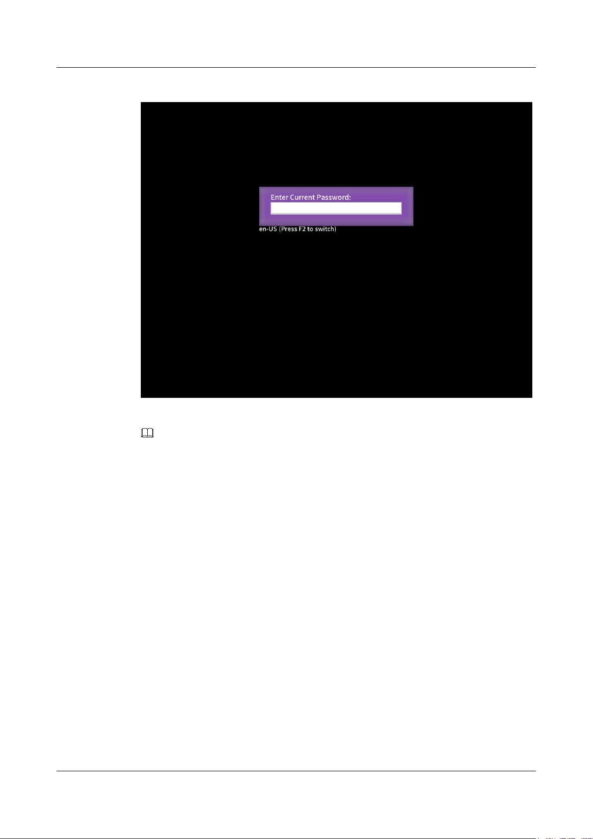
FusionServer Pro CH121 V5 Compute Node
User Guide
Figure 4-16 Entering the BIOS password
4 Installation and Configuration
Step 6 Enter the BIOS password.
NOTE
l The default BIOS password is Admin@9000.
l Press F2 to alternate between the English (US), French, and Japanese keyboards.
l Use the mouse to open the on-screen keyboard and enter the password.
l For security purposes, change the administrator password periodically.
l The system will be locked if an incorrect password is entered three consecutive times. You can
restart the compute node to unlock it.
The Setup Utility program is started.
Step 7 Select BIOS Configuration by pressing arrow keys.
The Main screen is displayed.
----End
4.3.7.2 Setting the System Boot Sequence
If multiple boot devices are configured for the compute node, you can set the system boot
sequence on the BIOS.
Procedure
Step 1 On the BIOS main screen, choose Boot.
The Boot screen is displayed.
Issue 06 (2019-08-10) Copyright © Huawei Technologies Co., Ltd. 88
Page 97

FusionServer Pro CH121 V5 Compute Node
User Guide
Step 2 Select Boot Type and press Enter.
The Boot Type dialog box is displayed.
Step 3 Select Legacy Boot or UEFI Boot, and then press Enter.
NOTE
l The default boot mode is UEFI.
l For some OSs, if the capacity of the drive or RAID array for installing the OS is greater than 2 TB,
use the UEFI boot mode. For details, see the release notes of the OS.
l If the OS is installed on an NVMe drive, the boot mode must be the UEFI boot.
l The UEFI boot mode supports more boot devices than the legacy boot mode. The UEFI boot mode
is recommended if a compute node is configured with multiple boot devices. If the legacy mode is
set, some devices may fail to boot. If the legacy mode has to be set, disable serial port redirection or
NIC PXE based on service requirements so that the OS can start. For details, see sections "Setting
PXE for a NIC" and "Setting Serial Port Redirection" in Huawei Server Purley Platform BIOS
Parameter Reference.
Step 4 Select Boot Sequence and press Enter.
The Boot Sequence screen is displayed.
4 Installation and Configuration
NOTE
The default boot sequence is Hard Disk Drive > DVD-ROM Drive > PXE > Others.
Step 5 Select the target boot device and press F5 or F6 to change the boot order.
l Press F5 to move a boot option down.
l Press F6 to move a boot option up.
NOTE
The server boots in the order specified on this screen.
----End
4.3.7.3 Setting PXE for a NIC
If a compute node is configured with multiple NICs, you can set the PXE function for the
NICs on the BIOS.
NOTE
If multiple boot devices of the same type are configured for a compute node, you can set the system boot
sequence on the BIOS. For details about how to set the boot device, see Huawei Server Purley
Platform BIOS Parameter Reference.
Procedure
Step 1 On the BIOS main screen, choose Advanced.
The Advanced screen is displayed.
Step 2 Select PXE Configuration and press Enter.
The PXE Configuration screen is displayed.
Issue 06 (2019-08-10) Copyright © Huawei Technologies Co., Ltd. 89
Page 98

FusionServer Pro CH121 V5 Compute Node
User Guide
NOTE
MAC information of two network ports can be displayed on the PXE screen. PXE setting is not
supported. The PXE function is enabled for the two network ports by default.
----End
4.3.7.4 Setting the BIOS Password
For security purposes, change the administrator password upon the first login.
NOTE
l The password complexity check function is enabled by default.
l You are advised to use a password that meets complexity requirements or to enable the password
complexity check function.
l For security purposes, change the administrator password periodically.
Procedure
Step 1 On the BIOS main screen, choose Security.
4 Installation and Configuration
The Security screen is displayed.
Step 2 Select Manage Supervisor Password and press Enter.
The Manage Supervisor Password screen is displayed.
Step 3 Change the BIOS password.
NOTE
l The current password of the system administrator is required before you change the password. The
system will be locked if an incorrect password is entered three consecutive times. You can unlock
the system by restarting it.
l The default BIOS password is Admin@9000.
l The requirements for setting the administrator password are as follows:
– The password must be a string of 8 to 16 characters and contain special characters (including
spaces) and at least two types of uppercase letters, lowercase letters, and digits.
– The previous five passwords cannot be reused as a new password.
– After the administrator password is set, the Delete Supervisor Password parameter is
displayed, which can be used to clear the administrator password.
– If Simple Password is set to Enabled, the system does not verify the password complexity,
but the password length must be 8 to 16 digits.
----End
4.3.7.5 Selecting a Language
Procedure
Step 1 On the BIOS main screen, choose Main.
The Main screen is displayed.
Step 2 Select Language and press Enter.
The Language screen is displayed.
Issue 06 (2019-08-10) Copyright © Huawei Technologies Co., Ltd. 90
Page 99
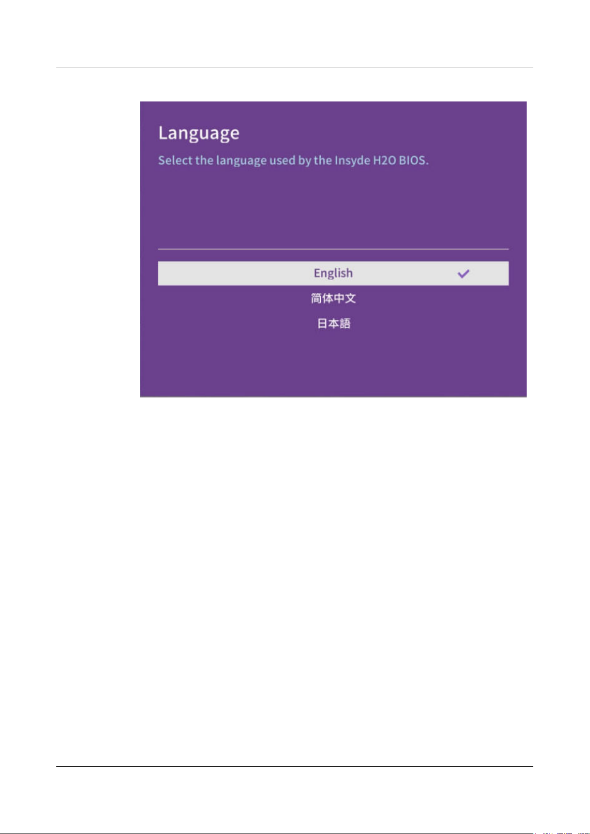
FusionServer Pro CH121 V5 Compute Node
User Guide
Figure 4-17 Selecting a language
4 Installation and Configuration
Step 3 Select the language to be used and press Enter.
The target language is set for the GUI.
----End
4.3.7.6 Restarting the Compute Node
After the settings, you need to restart the compute node for the settings to take effect.
Procedure
Step 1 On the BIOS, press F10.
The Save Changes&Exit dialog box is displayed.
Step 2 Select Yes and press Enter.
Settings are saved and the BIOS is exited. The compute node automatically restarts for the
settings to take effect.
----End
4.3.8 Installing an OS
The CH121 V5 supports multiple types of OSs.
l Use Intelligent Computing Compatibility Checker to obtain information about the
compatible operating systems.
Issue 06 (2019-08-10) Copyright © Huawei Technologies Co., Ltd. 91
Page 100

FusionServer Pro CH121 V5 Compute Node
User Guide
l The installation method varies with the operating system. For details, see Huawei
Server OS Installation Guide.
4 Installation and Configuration
Issue 06 (2019-08-10) Copyright © Huawei Technologies Co., Ltd. 92
 Loading...