

Page 1

ECC800 Data Center Controller
V100R001C40
User Manual
Issue
02
Date
2019-02-28
HUAWEI TECHNOLOGIES CO., LTD.
Page 2

Issue 02 (2019-02-28)
Copyright © Huawei Technologies Co., Ltd.
i
Copyright © Huawei Technologies Co., Ltd. 2019. All rights reserved.
No part of this document may be reproduced or transmitted in any form or by any means without prior
written consent of Huawei Technologies Co., Ltd.
Trademarks and Permissions
and other Huawei trademarks are trademarks of Huawei Technologies Co., Ltd.
All other trademarks and trade names mentioned in this document are the property of their respective
holders.
Notice
The purchased products, services and features are stipulated by the contract made between Huawei and
the customer. All or part of the products, services and features described in this document may not be
within the purchase scope or the usage scope. Unless otherwise specified in the contract, all statements,
information, and recommendations in this document are provided "AS IS" without warranties, guarantees or
representations of any kind, either express or implied.
The information in this document is subject to change without notice. Every effort has been made in the
preparation of this document to ensure accuracy of the contents, but all statements, information, and
recommendations in this document do not constitute a warranty of any kind, express or implied.
Huawei Technologies Co., Ltd.
Address:
Huawei Industrial Base
Bantian, Longgang
Shenzhen 518129
People's Republic of China
Website:
http://e.huawei.com
Page 3

ECC800 Data Center Controller
User Manual
About This Document
Issue 02 (2019-02-28)
Copyright © Huawei Technologies Co., Ltd.
ii
Purpose
Symbol
Description
Indicates an imminently hazardous situation which, if not avoided, will
result in serious injury or death.
Indicates a potentially hazardous situation which, if not avoided, could
result in serious injury or death.
Indicates a potentially hazardous situation which, if not avoided, may
result in minor or moderate injury.
About This Document
This document describes the ECC800 data center controller (including the ECC800e) in terms
of features, devices, user interfaces (UIs), and power-on commissioning, as well as frequently
asked questions (FAQ) and troubleshooting measures.
This document describes all the functions of the ECC800. Certain functions are implemented
by hardware such as the UPS and PDU, and may be unavailable if the hardware is not
connected to the ECC800.
The figures provided in this document are for reference only.
The software version is ECC800 V100R001C40SPC200.
Intended Audience
This document is intended for:
Sales engineers
Technical support engineers
Maintenance engineers
Symbol Conventions
The symbols that may be found in this document are defined as follows.
Page 4

ECC800 Data Center Controller
User Manual
About This Document
Issue 02 (2019-02-28)
Copyright © Huawei Technologies Co., Ltd.
iii
Symbol
Description
Indicates a potentially hazardous situation which, if not avoided, could
result in equipment damage, data loss, performance deterioration, or
unanticipated results.
NOTICE is used to address practices not related to personal injury.
Calls attention to important information, best practices and tips.
NOTE is used to address information not related to personal injury,
equipment damage, and environment deterioration.
Change History
Changes between document issues are cumulative. The latest document issue contains all
updates made in previous issues.
Issue 02 (2019-02-28)
Added information about USB ports.
Updated some MDU screenshots.
Updated the air conditioner name to smart cooling product.
Issue 01 (2017-10-13)
This issue is used for first office application (FOA).
Change points:
Optimized the scenario-based commissioning description for certain components.
Added some FAQ.
Issue Draft A (2017-02-15)
This issue is used for first application.
Page 5

ECC800 Data Center Controller
User Manual
Contents
Issue 02 (2019-02-28)
Copyright © Huawei Technologies Co., Ltd.
iv
Contents
About This Document ............................................................................................................ ii
1 Safety Precautions ................................................................................................................. 1
2 Overview ................................................................................................................................ 3
2.1 Positioning ............................................................................................................................................................................. 3
2.2 Application Scenarios ........................................................................................................................................................... 4
2.2.1 ECC800 system network diagram (FusionModule5000) ................................................................................................ 4
2.2.2 ECC800 system network diagram (FusionModule2000) ................................................................................................ 4
2.2.3 ECC800 system network diagram (FusionModule1000) ................................................................................................ 5
2.2.4 ECC800 system network diagram (FusionModule800) .................................................................................................. 6
2.2.5 ECC800e system network diagram (FusionModule500) ................................................................................................ 7
2.3 Features.................................................................................................................................................................................. 8
3 Device Description ................................................................................................................ 9
3.1 ECC800 ................................................................................................................................................................................. 9
3.2 ECC800e ............................................................................................................................................................................. 19
3.3 Southbound Device Introduction ....................................................................................................................................... 22
3.3.1 Rack Environment Unit ................................................................................................................................................... 22
3.3.2 Smart ETH Gateway........................................................................................................................................................ 24
3.3.3 General Input Unit ........................................................................................................................................................... 26
3.3.4 Power Distribution Unit .................................................................................................................................................. 28
3.3.5 Access Control System .................................................................................................................................................... 30
3.3.5.1 Aisle or Room Access Control System ....................................................................................................................... 30
3.3.5.1.1 Access Actuator ......................................................................................................................................................... 30
3.3.5.1.2 Fingerprint and Card Reader with a Keypad ........................................................................................................... 35
3.3.5.1.3 Fingerprint and Card Reader..................................................................................................................................... 36
3.3.5.1.4 Card Reader with a Keypad ...................................................................................................................................... 38
3.3.5.1.5 Magnetic Lock ........................................................................................................................................................... 39
3.3.5.2 Cabinet Access Control System ................................................................................................................................... 39
3.3.6 AC Actuator...................................................................................................................................................................... 41
3.3.7 Skylight Actuator ............................................................................................................................................................. 44
3.3.8 Multi-Functional Sensor .................................................................................................................................................. 46
3.3.9 Smoke Detector................................................................................................................................................................ 49
3.3.10 Temperature Sensor ....................................................................................................................................................... 49
Page 6

ECC800 Data Center Controller
User Manual
Contents
Issue 02 (2019-02-28)
Copyright © Huawei Technologies Co., Ltd.
v
3.3.11 Alarm Beacon................................................................................................................................................................. 50
3.3.12 Water Sensor .................................................................................................................................................................. 51
3.3.12.1 WLDS600 Water Sensor ............................................................................................................................................ 51
3.3.12.2 WLDS900 Water Sensor ............................................................................................................................................ 52
3.3.12.3 Electrode Water Sensor .............................................................................................................................................. 53
3.3.13 WiFi Converter .............................................................................................................................................................. 54
3.3.14 WiFi Module .................................................................................................................................................................. 56
3.3.15 ETH Converter............................................................................................................................................................... 57
3.3.16 Pad .................................................................................................................................................................................. 59
3.3.17 T/H Sensor ..................................................................................................................................................................... 61
3.3.17.1 T/H sensor (BOM number:33010346) ...................................................................................................................... 61
3.3.17.2 T/H Sensor (BOM number:02310NBS).................................................................................................................... 62
3.3.18 Infrared Remote Control Module ................................................................................................................................. 64
3.3.19 SMS Module .................................................................................................................................................................. 64
3.3.20 Intelligent Battery Monitoring System ......................................................................................................................... 65
3.3.20.1 CIM ............................................................................................................................................................................. 66
3.3.20.2 BIM ............................................................................................................................................................................. 76
4 UI Description ..................................................................................................................... 79
4.1 WebUI Introduction ............................................................................................................................................................ 79
4.1.1 Preparations and WebUI Login ....................................................................................................................................... 79
4.1.2 WebUI ............................................................................................................................................................................... 82
4.2 APP Introduction ................................................................................................................................................................. 84
4.2.1 Connecting to a WiFi Network ....................................................................................................................................... 84
4.2.2 Preparations and App Login ............................................................................................................................................ 86
4.2.3 Mobile Phone App ........................................................................................................................................................... 88
4.2.4 Pad App ............................................................................................................................................................................ 89
5 Power-On Commissioning ................................................................................................. 91
5.1 Setting the Date and Time .................................................................................................................................................. 91
5.2 Checking the System Type and Setting the Smart Module Name ................................................................................... 92
5.3 Setting and Adding Devices ............................................................................................................................................... 93
5.3.1 Setting Integrated UPS Parameters................................................................................................................................. 93
5.3.2 Setting and Adding a UPS2000-G .................................................................................................................................. 93
5.3.3 Setting and Adding a UPS5000-E................................................................................................................................... 95
5.3.4 Adding and Setting a SUNRISE-SCU-20K ................................................................................................................... 97
5.3.5 Setting NetCol5000-C030 Parameters (over Modbus TCP) ......................................................................................... 98
5.3.6 Setting and Adding a NetCol5000-C030 (over Modbus RTU)..................................................................................... 99
5.3.7 Setting the NetCol5000-A025 or NetCol5000-A010 Parameters(over MAC-Modbus)...........................................100
5.3.8 Setting and Adding a NetCol5000-A035 (over Modbus RTU) ..................................................................................101
5.3.9 Setting and Adding a PDU8000 or integrated PDU (over Modbus-TCP) .................................................................102
5.3.10 Setting and Adding a PDU8000 (over Modbus-RTU) ..............................................................................................102
5.3.11 Setting and Adding a PDU2000-M(C) .......................................................................................................................104
Page 7

ECC800 Data Center Controller
User Manual
Contents
Issue 02 (2019-02-28)
Copyright © Huawei Technologies Co., Ltd.
vi
5.3.12 Setting Parameters for the Smart Busway..................................................................................................................105
5.3.13 Setting and Adding an ATS .........................................................................................................................................107
5.3.14 Setting and Adding a PMAC625 AC Meter ...............................................................................................................108
5.3.15 Setting and Adding a PMAC615 AC Meter ............................................................................................................... 110
5.3.16 Setting and Adding a PDC DC Meter ........................................................................................................................ 111
5.3.17 Setting and Adding an Independent Deployment AI/DI Unit ................................................................................... 112
5.3.18 Setting and Adding an Smart Cooling Product .......................................................................................................... 114
5.3.19 Setting and Adding a 48 V DC Power Supply Device .............................................................................................. 115
5.3.20 Setting and Adding an AC or DC Meter .................................................................................................................... 116
5.3.21 Setting and Adding a Hydrogen Detection System ................................................................................................... 117
5.3.22 Adding a Networked Device ....................................................................................................................................... 119
5.4 Creating a Smart Module Plan View ...............................................................................................................................120
5.5 Setting Alarm Notification by Email and SMS...............................................................................................................122
5.6 Commissioning the AC Actuator (Wireless Networking) ..............................................................................................123
5.7 Commissioning Sensors ...................................................................................................................................................125
5.7.1 Commissioning a Multi-functional Sensor ..................................................................................................................125
5.7.2 Commissioning a Smoke Sensor ..................................................................................................................................127
5.7.2.1 Commissioning a Smoke Sensor (connected to the AI/DI port on the ECC800) ...................................................127
5.7.2.2 Commissioning a Smoke Sensor (Connected to the AI/DI port on the skylight actuator) ....................................128
5.7.3 Commissioning a Water Sensor ....................................................................................................................................129
5.7.3.1 Commissioning a WLDS900 water sensor ...............................................................................................................129
5.7.3.2 Commissioning a WLDS600 Water Sensor ..............................................................................................................129
5.7.3.3 Commissioning a Electrode water sensor .................................................................................................................131
5.7.4 Commissioning a Temperature Sensor .........................................................................................................................131
5.7.4.1 Commissioning a Temperature Sensor (Connected to the AI/DI port on the ECC800) ........................................131
5.7.4.2 Commissioning a Temperature Sensor (Connected to the NTC port on the rack environment unit) ...................132
5.7.5 Commissioning a T/H Sensor .......................................................................................................................................132
5.7.5.1 Commissioning a T/H Sensor (BOM number:33010346) .......................................................................................132
5.7.5.2 Commissioning a T/H Sensor (BOM number:02310NBS) .....................................................................................134
5.7.6 Commissioning a Door Status Sensor ..........................................................................................................................136
5.7.6.1 Commissioning a Door Status Sensor (Connected to the AI/DI port on the independent deployment AI/DI unit)
..................................................................................................................................................................................................136
5.7.6.2 Commissioning a Door Status Sensor (Connected to the AI/DI port on the rack environment unit) ...................136
5.7.7 Commissioning an Access Control Device and a Cabinet Electronic Lock ..............................................................137
5.7.8 Commissioning the Exit Button, Emergency Button, and Magnetic Lock ................................................................141
5.7.9 Commissioning an Emergency Door Release Button .................................................................................................142
5.8 Commissioning CIMs and BIMs .....................................................................................................................................143
5.9 Commissioning the Cameras and VCN500 (Smart ETH Gateway Networking Scenario) .........................................144
5.9.1 Configuring the VCN500 ..............................................................................................................................................145
5.9.2 Commissioning IPC6325 Cameras ...............................................................................................................................147
5.9.3 Adding a Camera on the VCN ......................................................................................................................................150
5.9.4 Setting and Viewing Videos on the ECC800 WebUI ..................................................................................................151
Page 8

ECC800 Data Center Controller
User Manual
Contents
Issue 02 (2019-02-28)
Copyright © Huawei Technologies Co., Ltd.
vii
5.9.5 Commissioning IPC6325 Camera (SD Card Configured) ..........................................................................................152
5.10 Commissioning Cameras and a VCN (LAN Switch Networking Scenario) ..............................................................154
5.10.1 Configuring the VCN500 ............................................................................................................................................155
5.10.2 Commissioning IPC6325 Cameras.............................................................................................................................157
5.10.3 Adding a Camera on the VCN500 ..............................................................................................................................159
5.10.4 Commissioning IPC6325 Camera (SD Card Configured) ........................................................................................160
5.11 Setting ECC800 Cascading ............................................................................................................................................164
6 Remote Management ........................................................................................................ 165
6.1 NetEco Management ........................................................................................................................................................165
6.1.1 Connecting the Communications Cable .......................................................................................................................165
6.1.2 Setting NetEco Parameters............................................................................................................................................165
6.1.3 Creating an ECC800 on the NetEco .............................................................................................................................166
6.2 Third-party NMS Management (over SNMP) ................................................................................................................167
6.2.1 Connecting the Communications Cable .......................................................................................................................167
6.2.2 Setting SNMP Management Parameters ......................................................................................................................168
7 Feature Description ........................................................................................................... 170
7.1 PLC Function ....................................................................................................................................................................170
7.1.1 PLC Introduction ...........................................................................................................................................................170
7.1.2 PLC Configuration Examples .......................................................................................................................................171
7.2 Linking Alarms with an Alarm Beacon ...........................................................................................................................174
7.2.1 Linking the Smoke Alarm with the Alarm Beacon......................................................................................................174
7.2.2 Linking the AI/DI Alarm with the Alarm Beacon .......................................................................................................174
7.3 Fire Linkage ......................................................................................................................................................................175
7.4 Linking the Emergency Fan .............................................................................................................................................176
7.5 Battery Shallow Discharge Test .......................................................................................................................................176
7.6 Control Management of the Infrared Remote Control Module .....................................................................................178
7.6.1 Connecting the Communications Cable .......................................................................................................................178
7.6.2 Setting and Adding an Infrared Remote Control Module ...........................................................................................178
7.6.3 Control Function of an Infrared Remote Control Module ..........................................................................................179
7.7 (Optional) iCooling Function ...........................................................................................................................................181
7.8 PUE Configuration Management.....................................................................................................................................183
7.8.1 Configuring PUE Standard Mode .................................................................................................................................183
7.8.2 Configuring PUE User-defined Mode ..........................................................................................................................185
8 Maintenance ....................................................................................................................... 188
8.1 Routine Maintenance ........................................................................................................................................................188
8.2 Common Faults and Troubleshooting..............................................................................................................................189
8.3 Component Replacement .................................................................................................................................................191
8.3.1 Replacing an ECC800 Main Control Module..............................................................................................................192
8.3.2 Replacing a PSU ............................................................................................................................................................193
8.3.3 Replacing ECC800 Antennas ........................................................................................................................................194
8.3.4 Replacing a SIM Card and Micro SD Card .................................................................................................................195
Page 9

ECC800 Data Center Controller
User Manual
Contents
Issue 02 (2019-02-28)
Copyright © Huawei Technologies Co., Ltd.
viii
9 FAQ ..................................................................................................................................... 197
9.1 WebUI Operations ............................................................................................................................................................197
9.1.1 How Can I View Version Information? ........................................................................................................................197
9.1.2 How to Manage WebUI Users? ....................................................................................................................................197
9.1.3 How to Restore Factory Settings? ................................................................................................................................198
9.1.4 How to Install a Network Security Certificate? ...........................................................................................................199
9.1.5 How Can I Install a Device Access Certificate? ..........................................................................................................200
9.1.6 How Can I Change the ECC800 IP Address on the WebUI? ......................................................................................201
9.1.7 How to Set Parameters for Alarm Enable, Severity, and Loudspeaker? ....................................................................201
9.1.8 How Can I View Real-Time Monitoring Data, Active Alarms, Historical Alarms, Access Event, and Operation
Logs? ........................................................................................................................................................................................202
9.1.9 How Can I View Performance Data? ...........................................................................................................................202
9.1.10 How Can I Export Historical Data and Device Data? ...............................................................................................202
9.1.11 How Can I Export or Import a Configuration File? ..................................................................................................203
9.1.12 How Can I Export Fault Information? .......................................................................................................................204
9.1.13 How Can I Synchronize Device Parameters? ............................................................................................................204
9.1.14 How to Associate an Alarm with a DO Output? ........................................................................................................205
9.1.15 How to Associate an Alarm Severity with a DO Output? .........................................................................................206
9.1.16 How Can I Handle DO Association Failure? .............................................................................................................206
9.1.17 What Do I Do If the ECC800 WebUI Display Language Changes from Chinese to English During Use? ..........207
9.1.18 How Can I Rectify Camera Access Restriction? .......................................................................................................207
9.1.19 How Should I Add the Devices Accessed Through a Smart ETH Gateway over Modbus-TCP to the ECC800
WebUI? ....................................................................................................................................................................................208
9.1.20 How Should I Add the Devices Accessed Through a Smart ETH Gateway over Modbus-MAC to the ECC800
WebUI? ....................................................................................................................................................................................209
9.1.21 How Should I Add Devices Accessed Through the ETH Converter to the ECC800 WebUI .................................210
9.1.22 How Should I Add Devices Accessed Through the ECC800 COM Port to the ECC800 WebUI .......................... 211
9.1.23 How Should I Add Devices Accessed Through the ECC800 AI/DI Port to the ECC800 WebUI ..........................213
9.1.24 How Should I Open Doors Remotely over the ECC800 WebUI ..............................................................................214
9.1.25 How Should I Turn On or Off Aisle Lights in the Smart Module over the ECC800 WebUI? ...............................215
9.1.26 How Should I Opening Skylights Remotely over the ECC800 WebUI? .................................................................216
9.1.27 How Should I Turn On or Off Smart Cooling Products over the ECC800 WebUI? ...............................................217
9.1.28 How Should I Open the Cabinet Electronic Lock over the ECC800 WebUI ..........................................................218
9.1.29 How Should I Modify Device Names over the ECC800 WebUI .............................................................................219
9.2 APP Operations .................................................................................................................................................................220
9.2.1 How to View Real-time Data? ......................................................................................................................................220
9.2.2 How Can I Export and Import Data? ............................................................................................................................220
9.2.3 How Can I Synchronize Device Parameters? ..............................................................................................................221
9.2.4 How Can I Handle App Login Failure?........................................................................................................................221
A Devices Connected to the ECC800 .................................................................................. 223
B Acronyms and Abbreviations .......................................................................................... 226
Page 10

ECC800 Data Center Controller
User Manual
1 Safety Precautions
Issue 02 (2019-02-28)
Copyright © Huawei Technologies Co., Ltd.
1
General Safety
1 Safety Precautions
Ensure that the product is used in environments that meet its design specifications to
avoid causing malfunctions or damaging components and voiding the warranty.
Personnel who plan to install or maintain Huawei equipment must receive a thorough
training, understand all necessary safety precautions, and be able to correctly perform all
operations.
Comply with local laws and regulations. The safety instructions in this manual are only
supplements to local laws and regulations.
Do not operate the product or handle cables during thunderstorms.
Before using the product, remove any conductors such as jewelry or watches.
Use insulated tools for all operations that involve electrical connections.
Follow specified procedures during installation and maintenance.
Before handling a conductor surface or terminal, measure the contact point voltage with
a multimeter, and ensure that the contact point has no voltage or the voltage is within the
allowed range.
Performing maintenance or locating faults may interrupt power to the loads if batteries
are not connected or the battery reserve is insufficient.
Before laying out power cables which have been stored in a temperature lower than 0°C,
move the power cables to an environment with room temperature and store them in the
environment for at least 24 hours.
Perform routine maintenance; replace faulty components at the earliest.
Electrical Safety
Grounding requirements
− When installing a device, install the ground cable first. When uninstalling a device,
− Before operating a device, ensure that the device is properly grounded.
AC and DC power
remove the ground cable at the very end.
Page 11

ECC800 Data Center Controller
User Manual
1 Safety Precautions
Issue 02 (2019-02-28)
Copyright © Huawei Technologies Co., Ltd.
2
The power system is powered by high-voltage power sources. Direct or indirect contact
(through damp objects) with high-voltage power sources may result in serious injury or
death.
Non-standard and improper operations may result in fire and electric shocks.
Before making electrical connections, turn off the protection switch on the upstream
device to cut the power supply.
Before connecting the AC power supply, ensure that electrical connections are complete.
Before connecting cables to loads or battery cables, check cable and terminal polarities
to avoid reverse connections.
Electrostatic discharge (ESD)
− To prevent electrostatic-sensitive components from being damaged by static from
human bodies, wear a grounded electrostatic discharge (ESD) wrist strap or ESD
gloves when touching circuit boards.
− When holding a board, hold its edge without touching any components, especially
chips.
− Package boards with ESD packaging materials before storing or transporting them.
Cable Layout
Mechanical Safety
Do not drill holes into a cabinet without permission. Non-standard drilling may affect the
electromagnetic shielding of the cabinet and damage interior cables. Metal shavings from
drilling may short-circuit circuit boards if they enter the cabinet.
Cables must be routed so that a sufficient distance exists between the cables and the DC
busbar, shunt, and fuse. This prevents damage to the insulation layer of the cables.
Signal cables must be bound separately from strong-current cables and high-voltage
cables.
Cables prepared by the customer must have the fire resistance capability.
Drilling holes
Before drilling holes into a cabinet, remove interior cables.
Wear goggles and protective gloves when drilling holes.
After drilling, clean up metal shavings immediately.
Moving heavy objects
− Be cautious to avoid injury when moving heavy objects.
− Wear protective gloves when moving sharp objects.
Page 12
ECC800 Data Center Controller
User Manual
2 Overview
Issue 02 (2019-02-28)
Copyright © Huawei Technologies Co., Ltd.
3
2.1 Positioning
The ECC800 is an intelligent data center environment and device management system which
features flexible layout, easy maintenance, and high reliability. The ECC800 is the core
component for the smart module local management. It adopts the PoE bus for expansion, and
allows all intelligent monitoring devices to be flexibly laid out so that it can manage the
devices in the smart module.
2 Overview
The ECC800 applies to the FusionModule5000, FusionModule2000, FusionModule1000, and
FusionModule800.
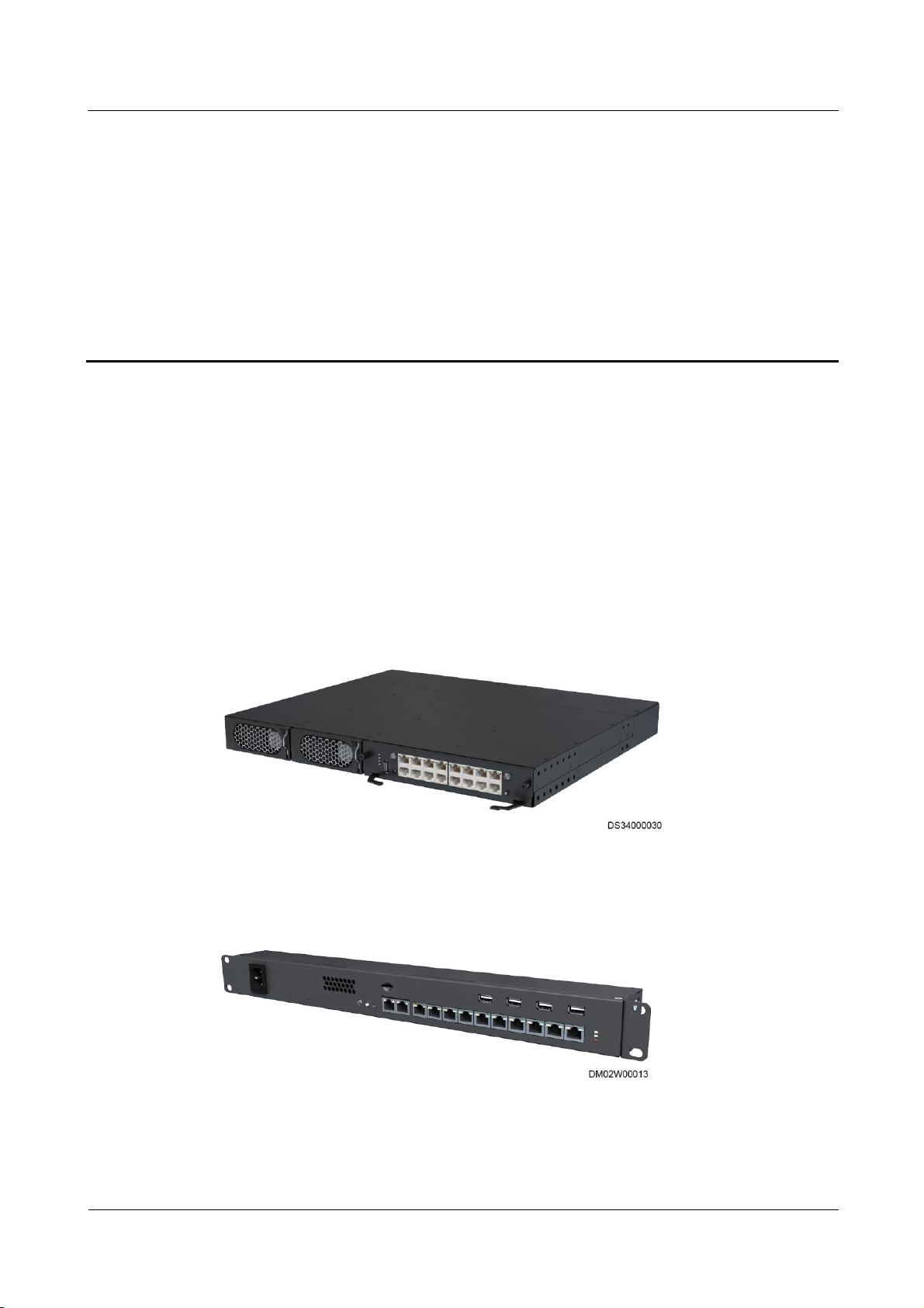
Figure 2-1 ECC800 appearance
The ECC800e is a lightweight ECC800, and only applies to the FusionModule500.
Figure 2-2 ECC800e appearance
Page 13

ECC800 Data Center Controller
User Manual
2 Overview
Issue 02 (2019-02-28)
Copyright © Huawei Technologies Co., Ltd.
4
2.2 Application Scenarios
2.2.1 ECC800 system network diagram (FusionModule5000)
The system network diagram uses FusionModule5000 V100R001C02 as an example.
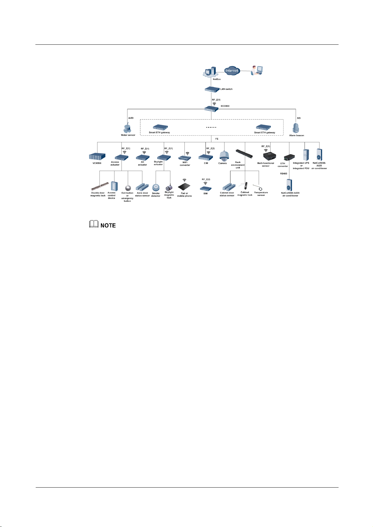
Figure 2-3 ECC800 system network diagram (FusionModule5000)
The new main way consists of general input units and power distribution units. It integrates the
smart ETH gateway and power distribution functions.
In the figure, RF_Z indicates wireless networking. RF_Z(1) devices can communicate with the
ECC800 in wireless mode. The RF_Z(2) BIM and CIM communicate with each other in wireless
mode. RF_Z(1) and RF_Z(2) devices use different protocols and are isolated from each other.
Wireless communication is automatically established after the access actuator, skylight actuator, and
multi-functional sensor successfully connect to and communicate with the ECC800 through PoE.
2.2.2 ECC800 system network diagram (FusionModule2000)
The system network diagram uses FusionModule2000 V500R002C01 as an example.
Page 14
ECC800 Data Center Controller
User Manual
2 Overview
Issue 02 (2019-02-28)
Copyright © Huawei Technologies Co., Ltd.
5
Figure 2-4 ECC800 system network diagram (FusionModule2000)
In the figure, RF_Z indicates wireless networking. RF_Z(1) devices can communicate with the
ECC800 in wireless mode. The RF_Z(2) BIM and CIM communicate with each other in wireless
mode. RF_Z(1) and RF_Z(2) devices use different protocols and are isolated from each other.
Wireless communication is automatically established after the access actuator, skylight actuator, and
multi-functional sensor successfully connect to and communicate with the ECC800 through PoE.
2.2.3 ECC800 system network diagram (FusionModule1000)
The system network diagram uses FusionModule1000 V200R003C00 as an example.
Page 15

ECC800 Data Center Controller
User Manual
2 Overview
Issue 02 (2019-02-28)
Copyright © Huawei Technologies Co., Ltd.
6
Figure 2-5 ECC800 system network diagram (FusionModule1000)
In the figure, RF_Z indicates wireless networking. RF_Z(1) devices can communicate with the
ECC800 in wireless mode. The RF_Z(2) BIM and CIM communicate with each other in wireless
mode. RF_Z(1) and RF_Z(2) devices use different protocols and are isolated from each other.
Wireless communication is automatically established after the access actuator, skylight actuator, and
multi-functional sensor successfully connect to and communicate with the ECC800 through PoE.
2.2.4 ECC800 system network diagram (FusionModule800)
The system network diagram uses FusionModule800 V100R001C01 as an example.
Page 16

ECC800 Data Center Controller
User Manual
2 Overview
Issue 02 (2019-02-28)
Copyright © Huawei Technologies Co., Ltd.
7
Figure 2-6 ECC800 system network diagram (FusionModule800)
In the figure, RF_Z indicates wireless networking. The RF_Z BIM and CIM communicate with each
other in wireless mode.
2.2.5 ECC800e system network diagram (FusionModule500)
The system network diagram uses FusionModule500 V100R001 as an example.
Figure 2-7 ECC800e system network diagram (FusionModule500)
Page 17

ECC800 Data Center Controller
User Manual
2 Overview
Issue 02 (2019-02-28)
Copyright © Huawei Technologies Co., Ltd.
8
2.3 Features
Efficient
− Supports access of wireless devices and provides backup routes, reducing cable
layout workload and enhancing reliability.
− Supports access right management in terms of the access card, password, and
fingerprint, providing high availability.
− Supports alarm notification by SMS and email, enabling remote maintenance.
− Supports cabinet-level magnetic locks, door status sensor, and temperature
monitoring, providing high security.
− Supports power supply and communication over the power over Ethernet (PoE) bus,
providing rich bandwidth resources and simplifying deployment.
− Supports remote upgrade, fault information export, and configuration parameter
synchronization.
− Connects to room-level access control devices and cameras.
− Cascades a maximum of three ECC800s; displays the active alarms and power
usage effectiveness (PUE) data of cascaded ECC800s on the WebUI of one
ECC800.
− Collects smart module PUE statistics and displays the statistics on a dashboard and
in curves. Users can query the power consumption of the smart module in real time.
− Supports intelligent iCooling management which allows changes in the cabinet
temperature and power consumption to cause intelligent adjustment and control for
the smart cooling product, thereby achieving energy conservation and emission
reduction. (Only FusionModule2000 supports the function.)
Simple
− Supports local WiFi hotspots. After you install the WiFi module at the USB port on
the ECC, you can connect to the ECC using the app on the mobile phone or tablet
computer to view the basic information about the smart module, such as layout,
resources, energy efficiency, environment, and alarms. This increases usability.
− Supports query of device information in real time using the pad app or mobile
phone app, facilitating operation and maintenance.
− Supports connection of monitoring devices to the PoE bus in plug-and-play mode
for auto-discovery and auto-registration requiring no configuration. This feature
enables fast delivery and higher maintainability.
Reliable
− Supports intelligent linkage management which allows customization of linkage
logic, achieving intelligent operation and maintenance.
− Supports dual power inputs, providing high reliability.
− Supports intelligent battery monitoring management, which allows monitoring of
individual cell voltage and internal resistance for discovery of failed cells.
− Supports interworking with the NetEco, supports the SNMP protocol, allowing
centralized management in various scenarios.
Page 18

ECC800 Data Center Controller
User Manual
3 Device Description
Issue 02 (2019-02-28)
Copyright © Huawei Technologies Co., Ltd.
9
3.1 ECC800
(1) PSU 1
(2) PSU 2
(3) Status indicator
(4) 3G/4G antenna port
Manufacturer: Guangdong
Shenglu Telecommunication Tech.
Co., Ltd.
Model: SL10802U
(5) FE ports
(WAN_1–WAN_2 and
LAN_1–LAN_2)
(6) AI/DI_1–6 sensor
input port
(7) RF_Z antenna port
Manufacturer: Guangdong
Shenglu Telecommunication Tech.
Co., Ltd.
Model: SL15334H
(8) SW button
(9) DO_1–2 dry contact
output
(10) RS485 port (COM1–4/12V)
(11) Default button
(12) USB port
(13) ECC800 main control module
The ECC800 consists of power supply units (PSUs) and an ECC800 main control module and
monitors the equipment and environment in the smart module.
Figure 3-1 ECC800 (front view)
3 Device Description
Page 19
ECC800 Data Center Controller
User Manual
3 Device Description
Issue 02 (2019-02-28)
Copyright © Huawei Technologies Co., Ltd.
10
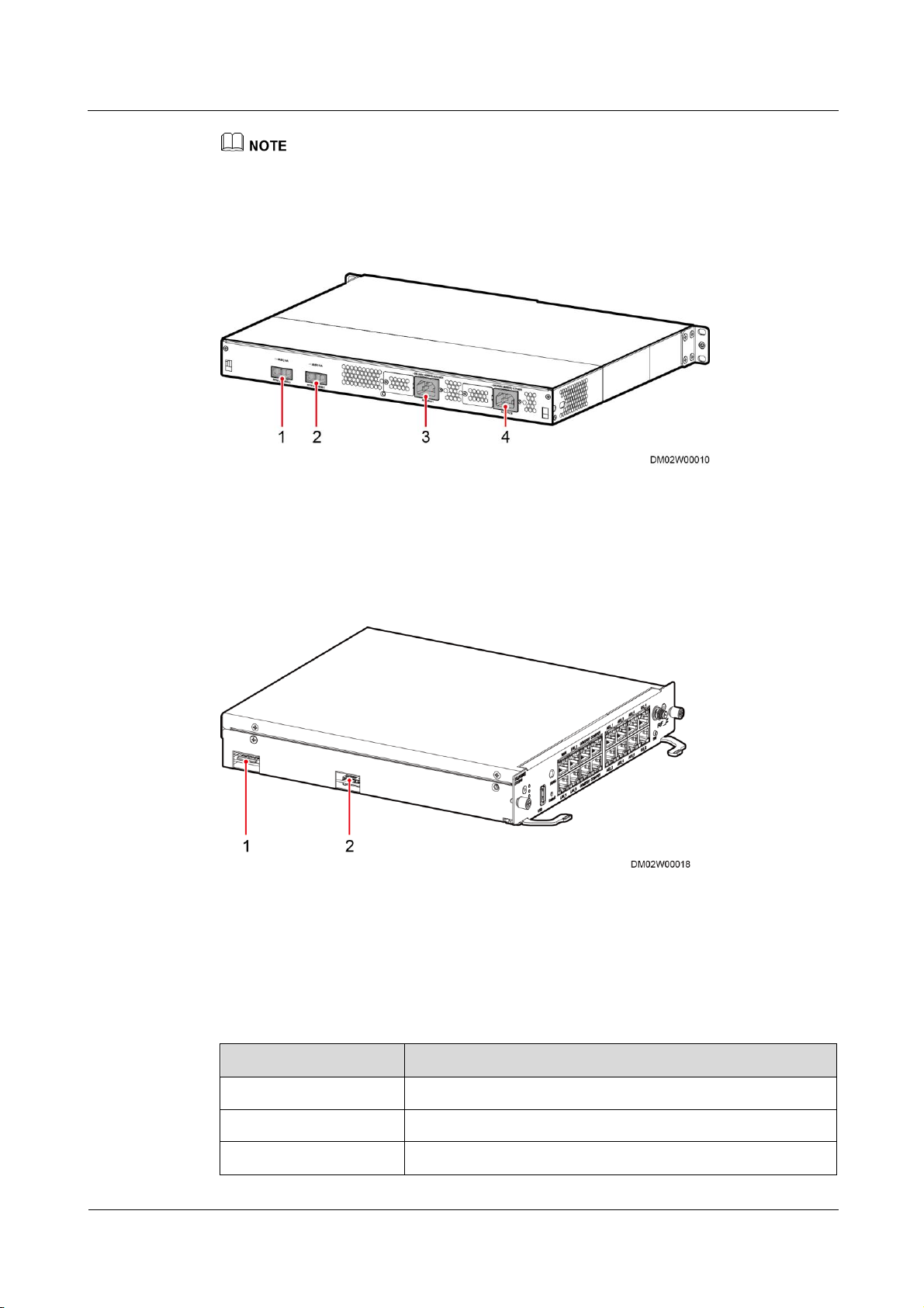
(1) 53.5 V DC_OUT1
(2) 53.5 V DC_OUT2
(3) AC_INPUT1
(4) AC_INPUT2
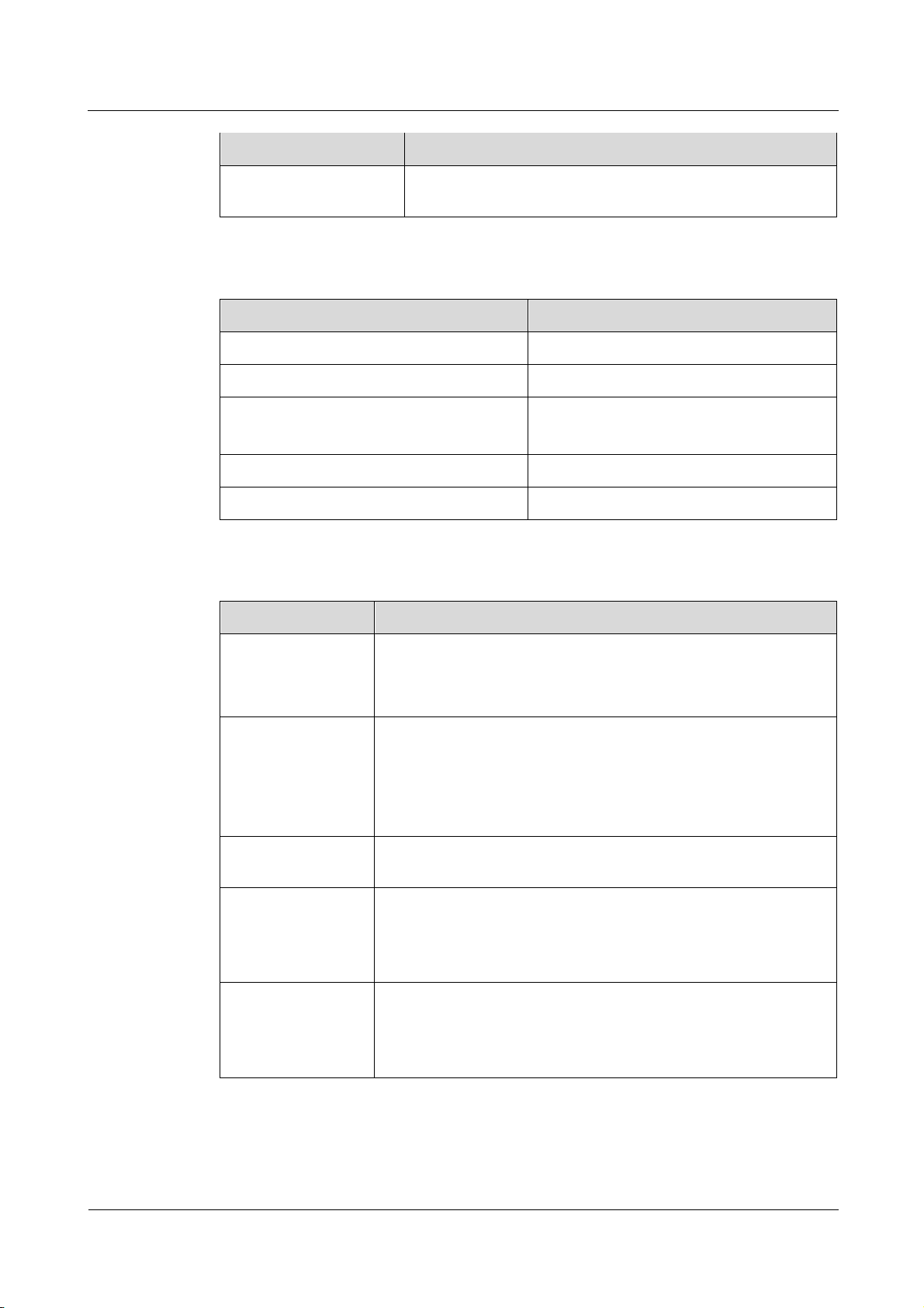
(1) SIM card slot
(2) Micro-SD card slot
Item
Specifications
Working temperature
–20°C to +50°C
Storage temperature
–40°C to +70°C
Relative humidity
5%–95% RH (non-condensing)
The ECC800 shown in the figure is fully configured with PSUs. PSUs 1 and 2 are optional depending on
the application scenario.
Figure 3-2 ECC800 (rear view)
Figure 3-3 ECC800 main control module (side view)
ECC800 Specifications
Table 3-1 ECC800 environmental specifications
Page 20
ECC800 Data Center Controller
User Manual
3 Device Description
Issue 02 (2019-02-28)
Copyright © Huawei Technologies Co., Ltd.
11
Item
Specifications
Altitude
0–4000 m (When the altitude is between 3000 m and 4000 m,
the temperature decreases by 1°C for each additional 200 m.)
Item
Specifications
Dimensions (L x W x H)
442 mm x 330 mm x 43.6 mm
Color
Black
Installation
Installed in a standard 1 U cabinet
Installed in a 19-inch rack
Environmental protection
RoHS5
Mean time between failures (MTBF)
500,000 hours
Item
Specifications
Power input
Supports two AC inputs
Rated voltage: 200–240 V AC/100–120 V AC
Rated frequency: 50 Hz/60 Hz
Power output
Output voltage: 42–58 V DC (rated voltage: 53.5 V DC)
Output power of two power supplies: 2000 W (176–300 V AC);
940 W (linear derating at 85–175 V AC)
Output power of a single power supply: 1000 W (176–300 V
AC); 470 W (linear derating at 85–175 V AC)
FE port expansion
Supports two WAN ports, two LAN ports, and 10/100M
communications rate
RS485 serial port
expansion
Supports four RS485 ports with the default communications rate
of 9600 bit/s.
Each port provides 12 V DC power with the rated current of 450
mA.
AI/DI expansion
(RJ45)
Supports six AI/DI ports to connect to smoke sensors, water
sensors, and temperature sensors.
Each port provides 12 V DC power with the rated current of 85
mA.
Table 3-2 ECC800 structural specifications
Table 3-3 ECC800 technical specifications
Page 21

ECC800 Data Center Controller
User Manual
3 Device Description
Issue 02 (2019-02-28)
Copyright © Huawei Technologies Co., Ltd.
12
Item
Specifications
DO expansion
(RJ45)
Two DO ports. Each port supports passive and active DO.
Supports passive (dry contact) DO ports with contact point
capacity of 20 W, maximum withstand voltage of 60 V DC, and
rated current of 500 mA.
Supports active DO ports with the output voltage of 12 V DC
and output current of 450 mA.
Wireless
communication
Supports wireless communication that complies with
IEEE802.15.4.
3G (optional)
Supports 3G (WCDMA) communication and is compatible with 2G
(GSM) communication. A standard SIM card slot is provided.
NOTE
The prerequisite for using a SIM card is that the site has signal coverage.
Supports only SMS but not data services.
USB After installing the WiFi module, connect the WiFi module to
the ECC using the app on the mobile phone or tablet computer
to view the basic information about the smart module, such as
layout, resources, energy efficiency, environment, and alarms.
Insert a USB flash drive to export historical data, device data,
fault information, and configuration files, and import or export
the device configuration data and historical data.
Button SW: wireless network pairing button
Default: restores the default IP address
Model Name
Specifications
ECC800
RF_Z operation frequency
2405 MHz–2480 MHz
RF_Z E.I.R.P.Power (Max.)
5 dBm
3G/4G Operation Frequency
WCDMA BAND: 850
MHz–2100 MHz
GSM: 850 MHz–1900 MHz
3G/4G E.I.R.P.Power
(Max.)
36 dBm
Driver version
V100
Table 3-4 ECC800 RF parameters
Page 22

ECC800 Data Center Controller
User Manual
3 Device Description
Issue 02 (2019-02-28)
Copyright © Huawei Technologies Co., Ltd.
13
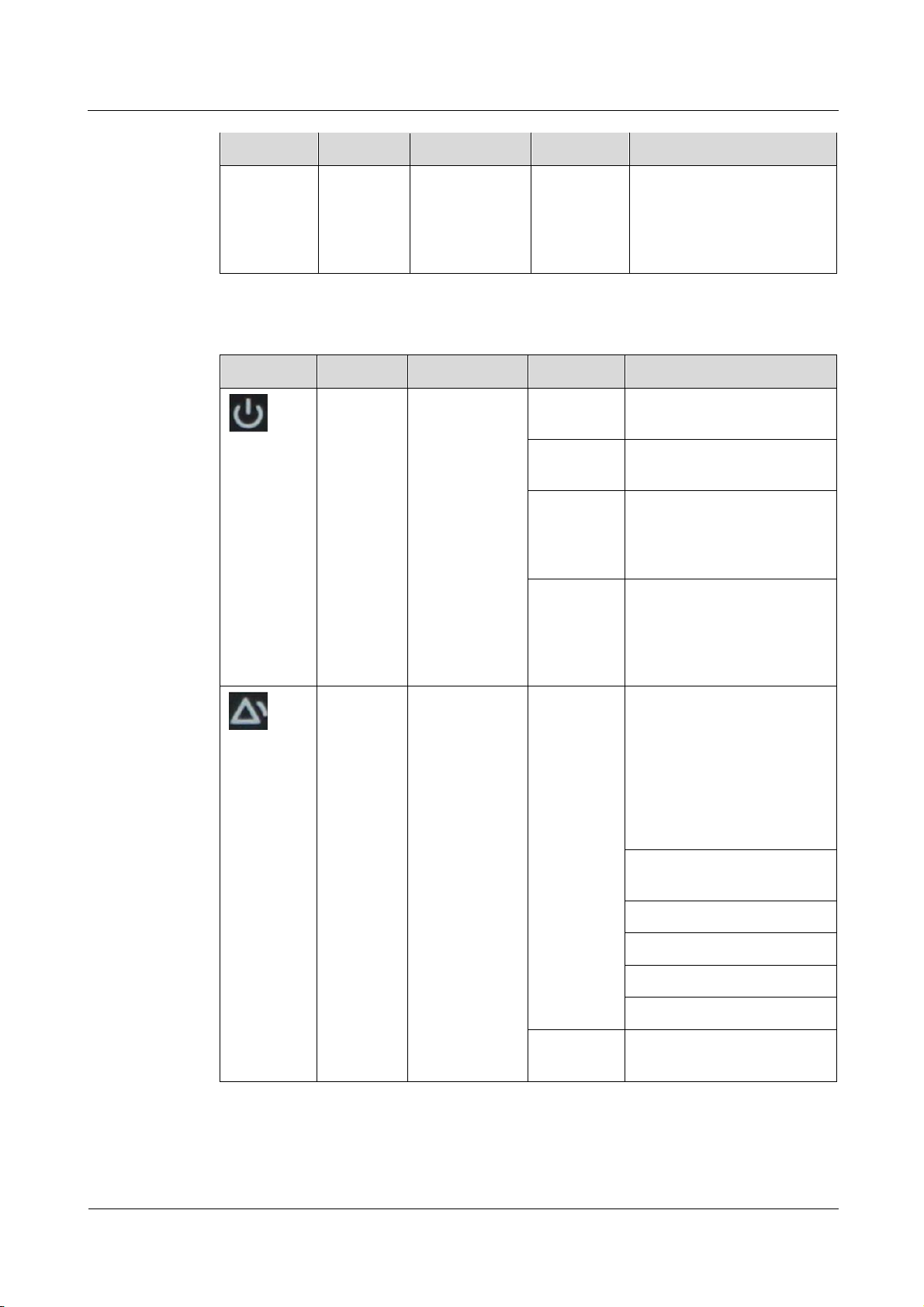
Indicators
Indicator
Color
Name
Status
Description
RUN
Green
Running status
indicator
Steady on
The power supply is normal,
the program is being loaded,
or WiFi WPS is pairing.
Off
The power supply is
abnormal.
Blinking at
long
intervals
The software runs properly
(the indicator blinks at 0.5
Hz, on for 1s and then off
for 1s) or the ECC800
registers with the NetEco
successfully.
Blinking at
short
intervals
The ECC800 does not
register with the NetEco (the
indicator blinks at 4 Hz, on
for 0.125s and then off for
0.125s).
ALM
Red
Alarm indicator
Steady on
A system failure alarm is
generated.
Off
The system is normal.
3G
Green
3G status
indicator
Steady on
The 3G module is powered
on.
Off
The 3G module stops
running, or no 3G module is
configured.
Blinking at
long
intervals
The 3G module succeeds in
dial-up (the indicator blinks
at 0.5 Hz, on for 1s and then
off for 1s).
Blinking at
short
intervals
The 3G module registers
with the operator network
successfully (the indicator
blinks at 4 Hz, on for 0.125s
and then off for 0.125s).
RF_Z
Green
Communication
status indicator
Steady on
No network parameters
exist, or a network is to be
created.
Blinking at
long
intervals
A network is set up, and no
node access is allowed (the
indicator blinks at 0.5 Hz, on
for 1s and then off for 1s).
Table 3-5 Indicators on the ECC800 main control module
Page 23
ECC800 Data Center Controller
User Manual
3 Device Description
Issue 02 (2019-02-28)
Copyright © Huawei Technologies Co., Ltd.
14
Indicator
Color
Name
Status
Description
Blinking at
super short
intervals
A network is set up, and
node access is allowed (the
indicator blinks at 10 Hz, on
for 0.05s and then off for
0.05s).
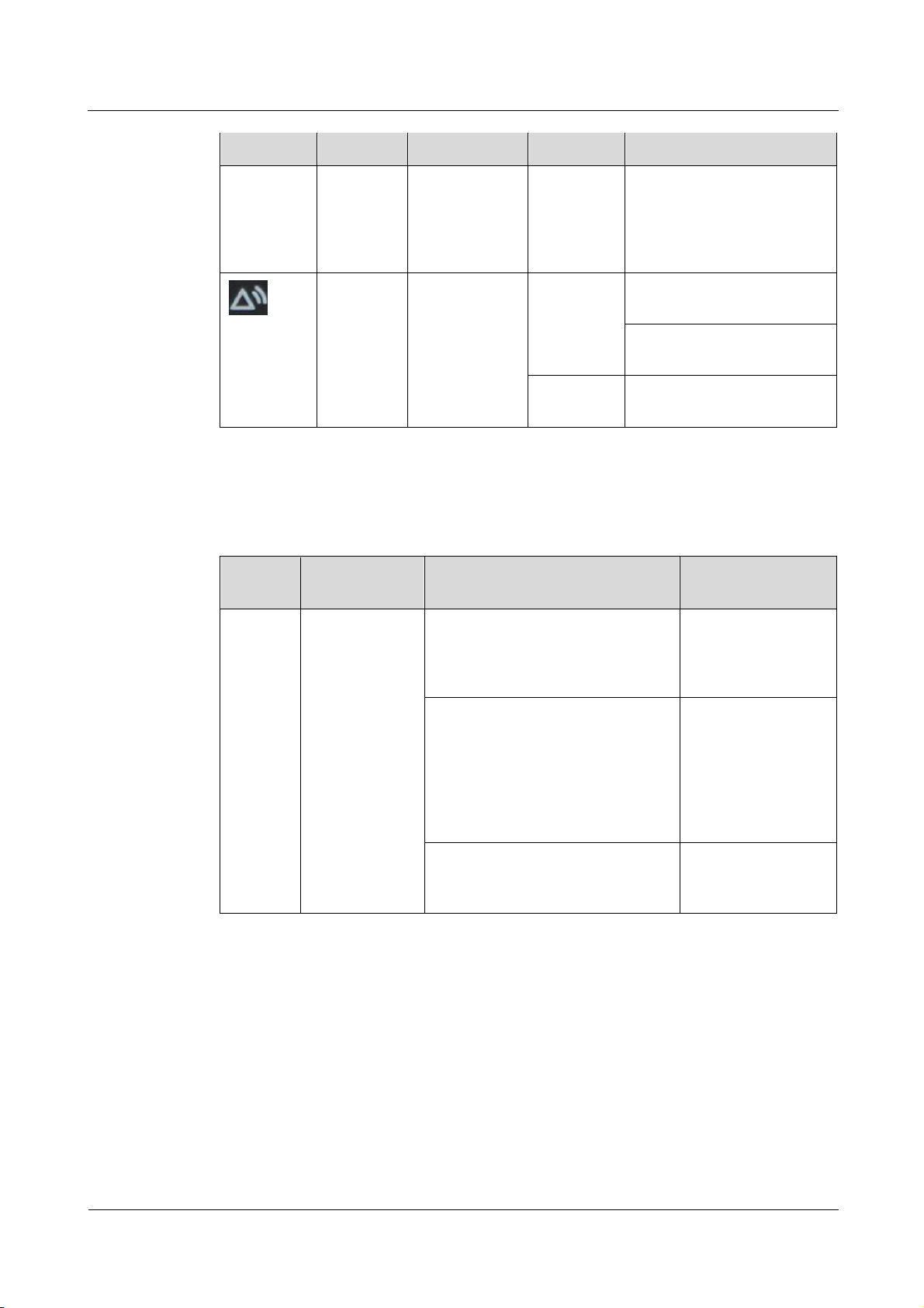
Indicator
Color
Name
Status
Description
Green
Power indicator
Steady on
The converter has a power
input.
Off
The converter has no power
input or is faulty.
Blinking at
long
intervals
The converter is being
queried (the indicator blinks
at 0.5 Hz, on for 1s and then
off for 1s).
Blinking at
short
intervals
The converter application
program is being loaded (the
indicator blinks at 4 Hz, on
for 0.125s and then off for
0.125s).
Yellow
Alarm indicator
Steady on
The converter generates a
forewarning indicating that
power will be limited due to
ambient overtemperature, or
generates a protection
shutdown alarm due to
ambient overtemperature or
undertemperature.
Power input overvoltage or
undervoltage protection
Reverse DC input connection
Slight current imbalance
Output overvoltage
Hibernation
Off
The converter generates no
protection alarms.
Table 3-6 PSU indicator description
Page 24
ECC800 Data Center Controller
User Manual
3 Device Description
Issue 02 (2019-02-28)
Copyright © Huawei Technologies Co., Ltd.
15
Indicator
Color
Name
Status
Description
Blinking at
long
intervals
The communication between
the converter and the outside
is interrupted (the indicator
blinks at 0.5 Hz, on for 1s
and then off for 1s).
Red
Fault indicator
Steady on
The converter locks out due
to output overvoltage.
The converter delivers no
output due to internal faults.
Off
The converter is working
properly.
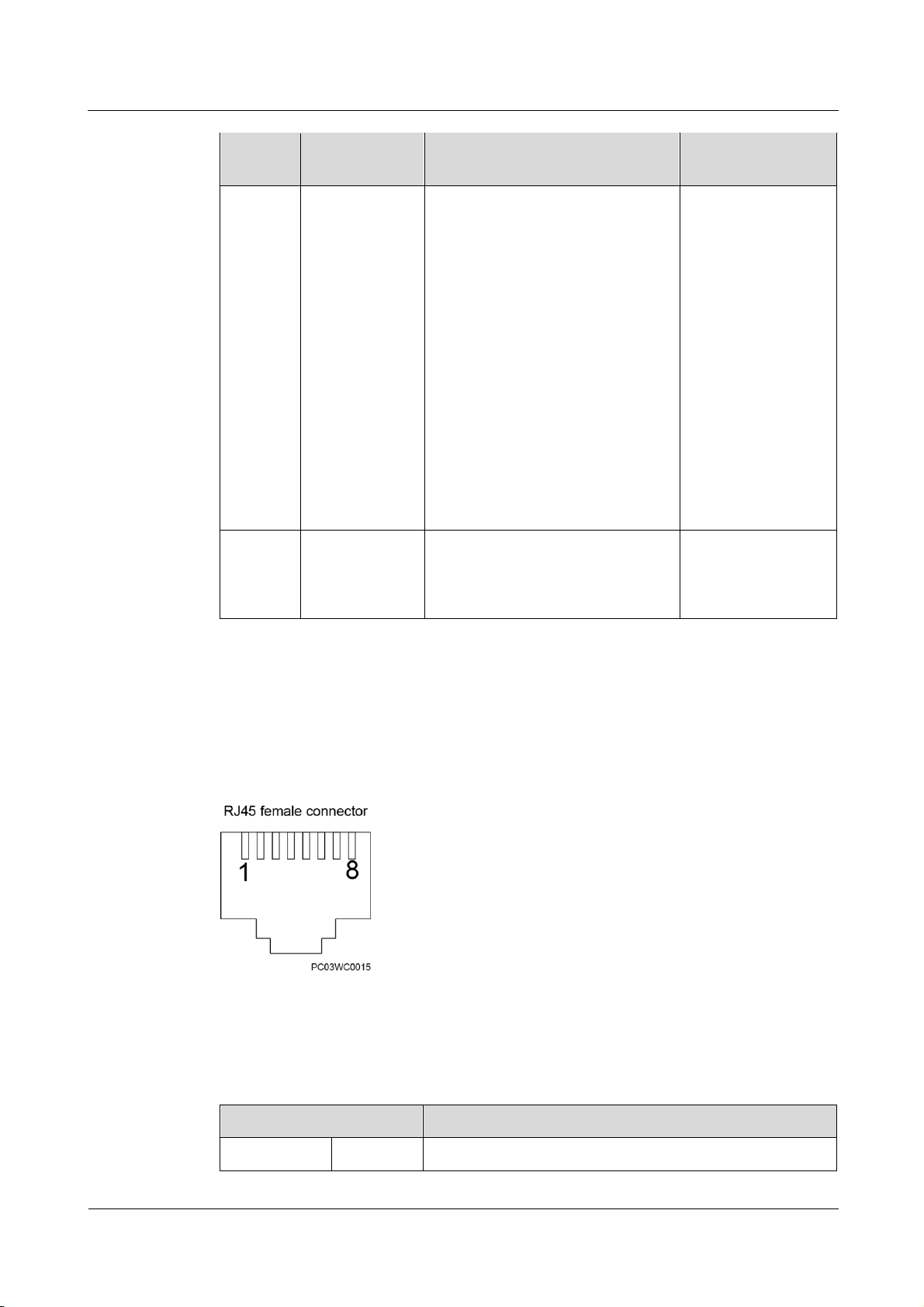
Button
Name
Function
Description
Operation Description
Indicator Status
SW
Wireless
network RF_Z
(802.15.4)
pairing
In non-wireless network (802.15.4)
pairing mode, press and hold down
the button for 1.2s to 5s to enter the
wireless network pairing mode.
The RF_Z indicator
is blinking at super
short intervals.
In wireless network (802.15.4)
pairing mode, press and hold down
the button for 1.2s to 5s to exit the
pairing mode; or the system
automatically exits the pairing mode
after 30 minutes without pressing
the button.
The RF_Z indicator
is blinking at long
intervals.
Press and hold down the button for
more than 6s to clear network
parameters.
The RF_Z indicator
is on.
Wireless Network Pairing (SW) and IP Address Reset (Default) Buttons
Table 3-7 Wireless network pairing and IP address reset buttons
Page 25
ECC800 Data Center Controller
User Manual
3 Device Description
Issue 02 (2019-02-28)
Copyright © Huawei Technologies Co., Ltd.
16
Button
Name
Function
Description
Operation Description
Indicator Status
WiFi pairing
button
NOTE
This function is
supported only
in a scenario
where the WiFi
converter is
configured.
In non-WiFi pairing mode, press the
button for less than 1.2s to enter the
WiFi pairing mode.
When the system
enters the pairing
mode, the RUN
indicator is
steady on.
After pairing
succeeds, the
RUN indicator
blinks just as
before WiFi
pairing.
If pairing does
not succeed in 3
minutes, the RUN
indicator blinks
just as before
WiFi pairing.
Default
IP address reset
Press and hold down the button for
3s. Then the IP address for the
ECC800 WAN_1 port will restore
to the default address 192.168.1.10.
None
Item
Description
Pin sequence
Pin 1
TX+
Communications Ports
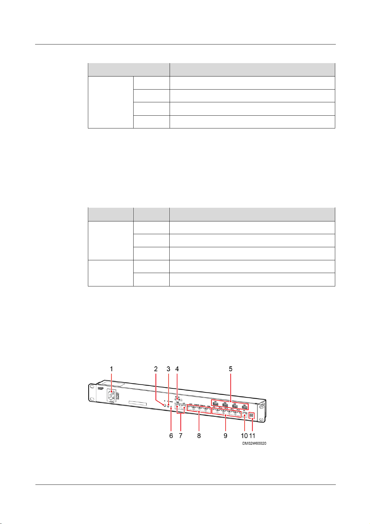
The ECC800 provides the following communications ports. Figure 3-4 shows the pins of the
RJ45 port.
Figure 3-4 RJ45 port pins
There are four FE ports, that is, two WAN ports (WAN_1 and WAN_2) and two LAN ports
(LAN_1 and LAN_2). Table 3-8 provides the FE port pin definitions.
Table 3-8 FE port pin definitions
Page 26

ECC800 Data Center Controller
User Manual
3 Device Description
Issue 02 (2019-02-28)
Copyright © Huawei Technologies Co., Ltd.
17
Item
Description
Pin 2
TX-
Pin 3
RX+
Pin 4
N/A
Pin 5
N/A
Pin 6
RX-
Pin 7
N/A
Pin 8
N/A
Indicator
Green
indicator
Linked, steady on
Yellow
indicator
ACT data communication, blinking
Item
Description
Pin sequence
Pin 1
RS485+
Pin 2
RS485–
Pin 3
12 V DC_OUT
Pin 4
RS485+
Pin 5
RS485–
Pin 6
N/A
Pin 7
N/A
Pin 8
GND
Indicator
Green
indicator
Power output indicator
Steady on: The 12 V DC output is normal.
Off: No 12 V DC output is provided.
There are four RS485 ports (COM1/12V–COM4/12V). Table 3-9 provides the RS485 port pin
definitions.
Table 3-9 RS485 port pin definitions
There are six AI/DI dry contact inputs (AI/DI_1–6). Table 3-10 provides the AI/DI port pin
definitions.
Pins 1, 2, 4, and 5 identify sensor types.
Pin 3 and Pin 8 are power output ports.
Page 27

ECC800 Data Center Controller
User Manual
3 Device Description
Issue 02 (2019-02-28)
Copyright © Huawei Technologies Co., Ltd.
18
Item
Description
Pin sequence
Pin 1
Type_1
Pin 2
Type_2
Pin 3
12 V DC
Pin 4
Type_3
Pin 5
Type_4
Pin 6
DI-
Pin 7
DI+
Pin 8
GND
Indicator
Green
indicator
Power output indicator
Steady on: The 12 V DC output is normal.
Off: No 12 V DC output is provided.
Item
Description
Pin sequence
Pin 1
N/A
Pin 2
N/A
Pin 3
12 V DC_OUT
Pin 4
N/A
Pin 5
N/A
Pin 6
DO_NO
Pin 7
DO_COM
Pin 8
GND
Indicator
Green
indicator
Power output indicator
Steady on: The 12 V DC output is normal.
Off: No 12 V DC output is provided.
Pin 6 and Pin 7 collect sensor data. Pin 7 can detect current type sensors (4–20 mA). Pin 6 and Pin 7
can detect the output status of passive dry contact type sensors. Pin 3 and Pin 7 can detect
temperature sensors.
Table 3-10 AI/DI port pin definitions
There are two DO dry contact outputs (DO_1 and DO_2). Table 3-11 provides the DO port
pin definitions.
Table 3-11 DO port pin definitions
Page 28
ECC800 Data Center Controller
User Manual
3 Device Description
Issue 02 (2019-02-28)
Copyright © Huawei Technologies Co., Ltd.
19
Item
Description
Pin sequence
Pin 1
5 V
Pin 2
DM
Pin 3
DP
Pin 4
GND
Power Ports
Port Type
Pin
Description
AC
Pin 1
L
Pin 2
PE
Pin 3
N
DC
Pin 1
48V+
Pin 2
48VGND
(1) Power input
(2) Infrared receiver (IR)
(3) SW button
Table 3-12 USB port pin definitions
The ECC800 provides four power ports, including two AC input ports (AC_INPUT1 and
AC_INPUT2) and two DC output ports (DC_OUTPUT1 and DC_OUTPUT2). Table 3-13
provides the power port pin definitions.
Table 3-13 Power port pin definitions
3.2 ECC800e
The ECC800e monitors the equipment and environment inside the smart module.
Figure 3-5 ECC800e appearance
Page 29

ECC800 Data Center Controller
User Manual
3 Device Description
Issue 02 (2019-02-28)
Copyright © Huawei Technologies Co., Ltd.
20
socket
(4) Port for installing
a micro SD card
(5) USB (USB1–USB4) port
(6) Default button
(7) FE port (WAN
port and LAN port)
(8) RS485 port (COM1,
COM2–3/12V) and CAN port
(COM4)
(9) AI/DI_1–5 sensor input
ports
(10) DO dry contact
(11) Status indicator
Item
Specification
Power Input
Supports one AC input.
Rated operating voltage: 100-240 V AC.
Rated operating frequency: 50 Hz/60 Hz.
Input current: MAX 0.5 A.
FE port expansion
Supports one WAN port, one LAN port, with the 10/100M
communications rate.
RS485 serial port
expansion
Reserves three RS485 ports with the default communications
rate of 9600 bit/s.
COM2–3 ports providing 12 V DC power with the rated current
of 450 mA.
NOTE
The Pin 1, Pin 2, Pin 4, and Pin 5 in the COM4 port provide the RS485
signal. These four pins are shared with the COM3 port.
The Pin 7 and Pin 8 in the COM4 port provide the CAN signal.
AI/DI expansion
(RJ45)
Supports five AI/DI ports to connect to smoke sensors, water
sensors, and temperature sensors.
Each port provides 12 V DC power with the rated current of 85
mA.
DO expansion
(RJ45)
One DO port supports passive and active DO.
Supports passive (dry contact) DO port with contact point
capacity of 20 W, maximum withstand voltage of 60 V DC, and
rated current of 0.5 A.
Supports active DO port with the output voltage of 12 V DC and
output current of 450 mA.
Table 3-14 Technical specifications
Page 30

ECC800 Data Center Controller
User Manual
3 Device Description
Issue 02 (2019-02-28)
Copyright © Huawei Technologies Co., Ltd.
21
Item
Specification
USB After installing the WiFi module, connect the WiFi module to
the ECC using the app on the mobile phone or tablet computer
to view the basic information about the smart module, such as
layout, resources, energy efficiency, environment, and alarms.
Insert the SMS module. When an alarm is reported, the ECC can
send information to the user through the 3G module.
Insert a USB flash drive to export historical data, device data,
fault information, and configuration files, and import or export
the device configuration data and historical data.
Buttons
SW: wireless network pairing button.
Default: button of restoring the default IP address.
Indicator
Color
Name
Status
Description
RUN
Green
Module running
status indicator
Steady on
The power supply is normal,
the program is being loaded,
or WiFi WPS is pairing.
Off
The power supply is
abnormal.
Blinking
at long
intervals
The software runs properly
(the indicator blinks at 0.5
Hz, on for 1s and then off
for 1s) or the ECC800e
registers with the NetEco
successfully.
Blinking
at short
intervals
The ECC800e does not
register with the NetEco (the
indicator blinks at 4 Hz, on
for 0.125s and then off for
0.125s).
ALM
Red
Alarm indicator
Steady on
A system failure alarm is
generated.
Off
The system is normal.
PWR
Green
Power indicator
Steady on
The power supply for the
system is normal.
Off
The power supply for the
system is abnormal.
Table 3-15 Indicators on the ECC800e main control module
Page 31
ECC800 Data Center Controller
User Manual
3 Device Description
Issue 02 (2019-02-28)
Copyright © Huawei Technologies Co., Ltd.
22
Table 3-16 Wireless network pairing and IP address reset buttons
Name
Function Description
Operation Description
SW
Reserved
N/A
Default
IP address reset
Press and hold down the
button for 3s. Then the IP
address for the ECC800e
WAN port will restore to the
default address
192.168.1.10.
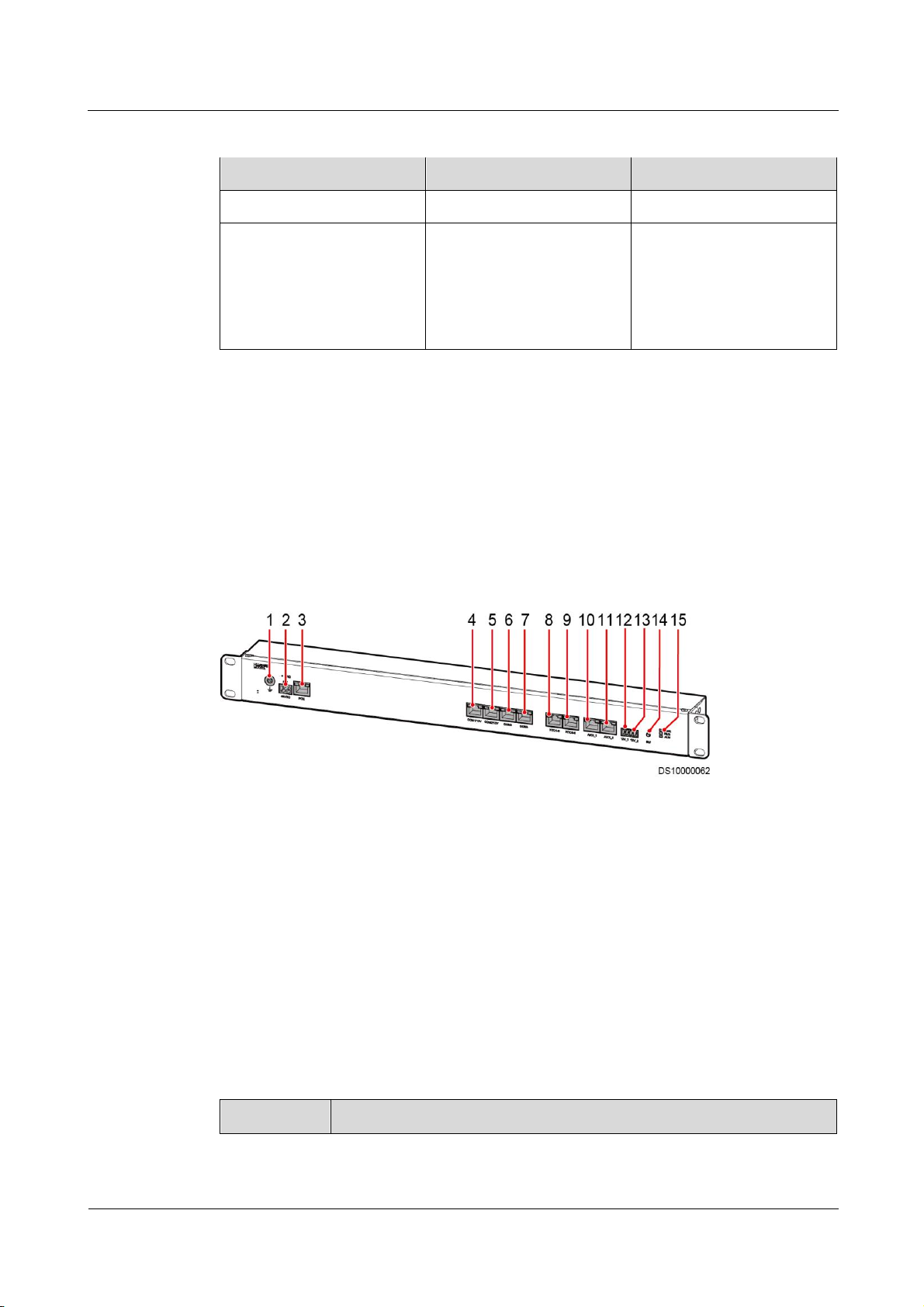
(1) Ground port
(2) 48 V DC power input
port
(3) PoE port
(4) COM1/12V
port
(5) COM2/12V
port
(6) COM3 port
(7) COM4 port
(8) NTC1-3
(9) NTC4-6
(10) AI/DI_1 port
(11) AI/DI_2 port
(12) 12V_1 port
(13) 12V_2 port
(14) BLINK button
(15) Status
indicator
Item
Specifications
3.3 Southbound Device Introduction
3.3.1 Rack Environment Unit
The rack environment unit collects and controls the environmental data of IT cabinets in the
smart module.
Specifications
Figure 3-6 Rack environment unit
Table 3-17 Technical specifications for the rack environment unit
Page 32

ECC800 Data Center Controller
User Manual
3 Device Description
Issue 02 (2019-02-28)
Copyright © Huawei Technologies Co., Ltd.
23
Item
Specifications
Power input
DC input: Terminal, with input voltage of 36–60 V DC
PoE input: One PoE port that complies with IEEE802.3at.
12 V power
output
Two 12 V DC power outputs with the rated output current of 250 mA
PoE port
FE communication with the rate of 10/100M
RS485 serial
port
expansion
Four RS485 ports with the default communications rate of 9600 bit/s
Among the four RS485 ports, two support 12 V DC, 400 mA power
output.
The other two are isolated, with the default communications rate of
9600 bit/s, and do not support power output.
AI/DI input
Two active 12 V DC, 200 mA AI/DI input ports
Temperature
sensor port
Provides two RJ45 ports to connect to six temperature sensors, each RJ45
port connecting to three temperature sensors.
BLINK
button
Provides a BLINK function.
Indicator
Color
Name
Status
Description
PWR
Green
Power input
status
indicator
Steady on
The power input is normal.
Off
There is no power input.
RUN
Green
Module
running
status
indicator
Off
The power is abnormal or
the board program is
loading.
Blinking at
long
intervals
The software runs properly
(the indicator blinks at 0.5
Hz, on for 1s and then off
for 1s).
Blinking at
short
intervals
PoE communication fails
(the indicator blinks at 4 Hz,
on for 0.125s and then off
for 0.125s).
Indicators
Table 3-18 lists the structural specifications for the rack environment unit.
Table 3-18 Indicator description
Page 33
ECC800 Data Center Controller
User Manual
3 Device Description
Issue 02 (2019-02-28)
Copyright © Huawei Technologies Co., Ltd.
24
Indicator
Color
Name
Status
Description
Blinking
The indicator blinks at super
short intervals for 0.5s
(blinking at 10 Hz, on for
0.05s and then off for 0.05s)
and then turns off for 0.5s.
The cycle lasts for 10s.
ALM
Red
Alarm
indicator
Steady on
A system failure alarm is
generated.
Off
No system alarm is
generated.
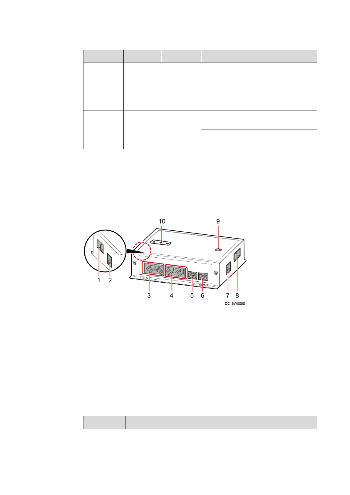
(1) PWR_IN
cascading power port
(2) FE_1 cascading
signal port
(3) PoE_1–2 ports
(4) PoE_3–4 ports
(5) 48V_OUT1
power output port
(6) 48V_OUT2
power output port
(7) FE_2
cascading signal
port
(8) PWR_OUT
cascading power port
(9) BLINK button
(10) Status indicator
Item
Specifications
3.3.2 Smart ETH Gateway
A smart ETH gateway allows the extension of the 53.5 V DC power supply and FE
communication for the ECC800 and can be flexibly deployed in a smart module.
Figure 3-7 Smart ETH gateway
Specifications
Table 3-19 Technical specifications for a smart ETH gateway
Page 34

ECC800 Data Center Controller
User Manual
3 Device Description
Issue 02 (2019-02-28)
Copyright © Huawei Technologies Co., Ltd.
25
Item
Specifications
Power input
PWR_IN D-type power input terminal, for power cascading, input voltage
range: 45–55 V DC
Power output
PWR_OUT D-type power output terminal, for power cascading, output
voltage range: 45–55 V DC
48V_OUT1 and 48V_OUT2, terminal, output voltage range: 45–55 V
DC
FE port
Two FE ports, RJ45 terminal with an indicator, 10/100M communication
rate, for the cascading between smart ETH gateways and the
communication with the upper computer
PoE port
Four PoE ports, RJ45 terminal with an indicator, 10/100M
communications rate, complying with IEEE802.3at
BLINK
button
If you press the BLINK button, the RUN indicator blinks intermittently at
super short intervals (blinking at super short intervals for 0.5s and then off
for 0.5s) for 10 seconds.
Indicator
Color
Name
Status
Description
PWR
Green
Power input
status indicator
Steady on
The power input is normal.
Off
There is no power input.
RUN
Green
Module
running status
indicator
Off
The power supply is
abnormal.
Blinking at
long
intervals
The smart ETH gateway
successfully registers with
the ECC800 and the software
runs properly (the indicator
blinks at 0.5 Hz, on for 1s
and then off for 1s).
Blinking at
short
intervals
The smart ETH gateway does
not register with the ECC800
(the indicator blinks at 4 Hz,
on for 0.125s and then off for
0.125s).
Blinking
The indicator blinks at super
short intervals for 0.5s
(blinking at 10 Hz, on for
0.05s and then off for 0.05s)
and then turns off for 0.5s.
The cycle lasts for 10s.
Indicators
Table 3-20 Indicators on a smart ETH gateway
Page 35
ECC800 Data Center Controller
User Manual
3 Device Description
Issue 02 (2019-02-28)
Copyright © Huawei Technologies Co., Ltd.
26
Indicator
Color
Name
Status
Description
ALM
Red
Alarm
indicator
Steady on
A system failure alarm is
generated.
Off
No system alarm is
generated.
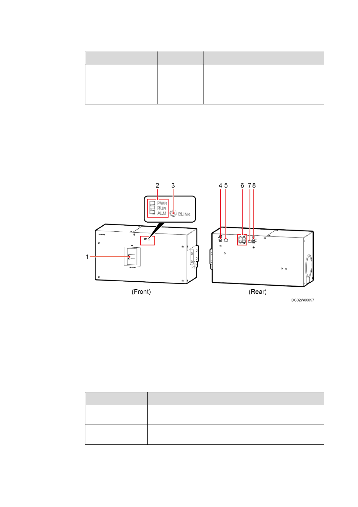
(1) QF circuit
breaker
(2) Status indicator
(3) BLINK button
(4) PWR_OUT
cascading power
port
(5) FE2 cascading
signal port
(6) PoE1–4 ports
(7) FE1 cascading
signal port
(8) PWR_IN
cascading power
port
Item
Specifications
Power input
PWR_IN power input terminal, for power cascading, input voltage
range: 45–55 V DC.
Power output
PWR_OUT power output terminal, for power cascading, output
voltage range: 45–55 V DC.
3.3.3 General Input Unit
The general input unit integrates the smart ETH gateway and power distribution functions. It
provides external power ports for the bus system to collect, count, and report input electrical
parameters.
Figure 3-8 General input unit
Table 3-21 Technical specifications of the general input unit
Page 36

ECC800 Data Center Controller
User Manual
3 Device Description
Issue 02 (2019-02-28)
Copyright © Huawei Technologies Co., Ltd.
27
Item
Specifications
FE port
Two FE ports, RJ45 terminal with an indicator, 10/100M
communications rate, for cascading between the general input unit
and the power distribution unit and for communication with the
upstream device.
PoE port
Four PoE ports, RJ45 terminal with an indicator, 10/100M
communications rate, 45–55 V DC power output.
BLINK button
If you press the BLINK button, the RUN indicator blinks
intermittently at super short intervals (blinking at super short
intervals for 0.5s and then off for 0.5s) for 10s.
Indicator
Color
Name
Status
Description
PWR
Green
Power input
status indicator
Steady on
The power input is
normal.
Off
There is no power
input.
RUN
Green
Module running
status indicator
Off
The power input is
abnormal.
Blinking at long
intervals
The general input unit
has successfully
registered with the
ECC800 and the
software runs properly
(blinking at 0.5 Hz, on
for 1s and then off for
1s).
Blinking at short
intervals
The general input unit
has failed to register
with the ECC800
(blinking at 4 Hz, on
for 0.125s and then off
for 0.125s).
Blinking
The indicator blinks at
super short intervals
(blinking at 10 Hz, on
for 0.05s and then off
for 0.05s) for 0.5s, and
then turns off for 0.5s.
The cycle lasts for
10s.
ALM
Red
Alarm indicator
Steady on
A system failure alarm
is generated.
Table 3-22 Indicators on the general input unit
Page 37
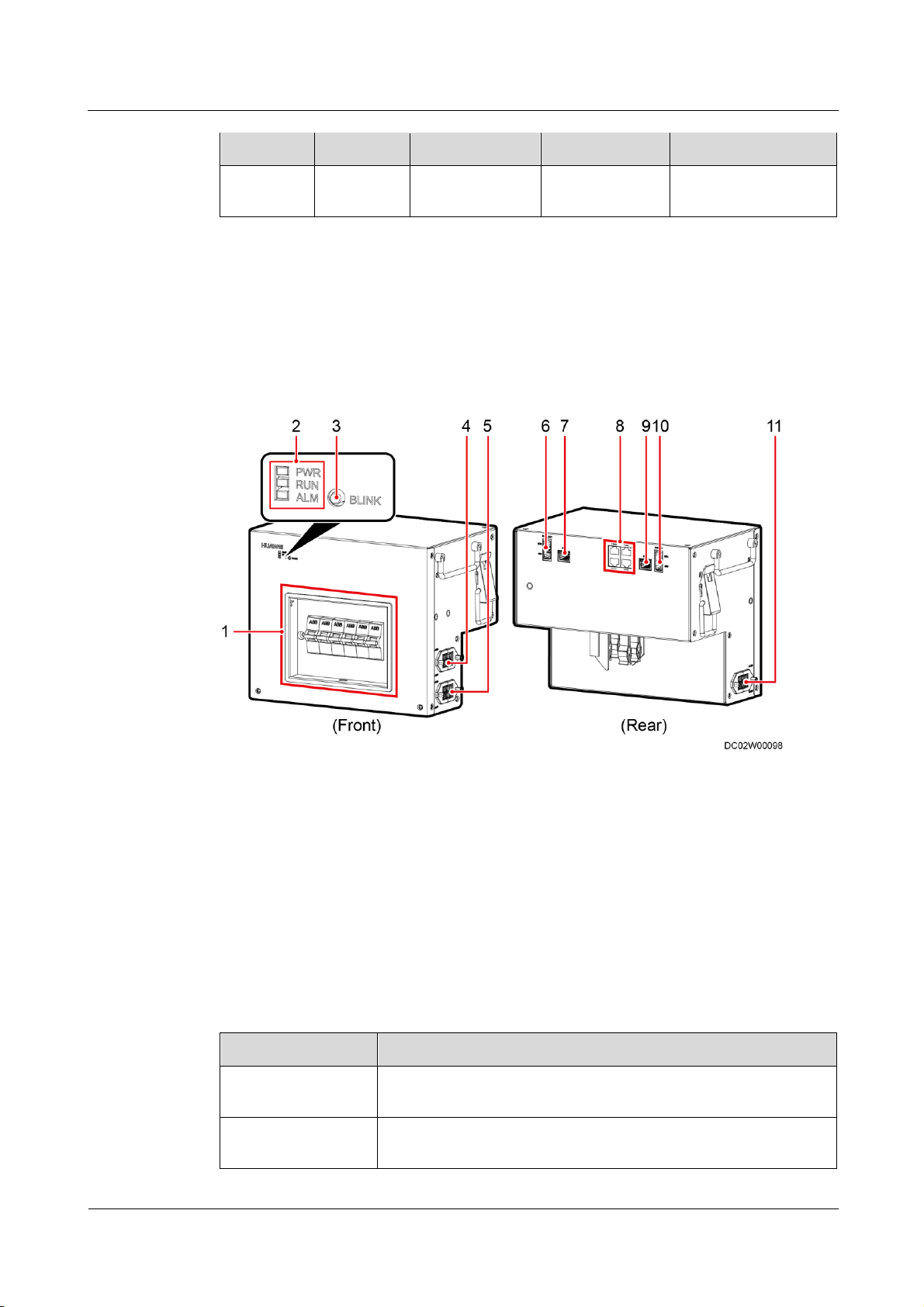
ECC800 Data Center Controller
User Manual
3 Device Description
Issue 02 (2019-02-28)
Copyright © Huawei Technologies Co., Ltd.
28
Indicator
Color
Name
Status
Description
Off
No system alarm is
generated.
(1) QF1–6 circuit
breakers
(2) Status indicator
(3) BLINK button
(4) AC output
terminal
(5) AC output
terminal
(6) PWR_OUT
cascading power
port
(7) FE2 (Fast
Ethernet) cascading
signal port
(8) PoE1–4 ports
(9) FE1 cascading
signal port
(10) PWR_IN
cascading power
port
(11) AC output
terminal
Item
Specifications
Power input
PWR_IN power input terminal, for power cascading, input voltage
range: 45–55 V DC
Power output
PWR_OUT power output terminal, for power cascading, output
voltage range: 45–55 V DC
3.3.4 Power Distribution Unit
The power distribution unit integrates the smart ETH gateway and power distribution
functions. It provides external power ports for the bus system to collect, count, and report
output electrical parameters.
Figure 3-9 Power distribution unit
Table 3-23 Technical specifications of the power distribution unit
Page 38

ECC800 Data Center Controller
User Manual
3 Device Description
Issue 02 (2019-02-28)
Copyright © Huawei Technologies Co., Ltd.
29
Item
Specifications
FE port
Two FE ports, RJ45 terminal with an indicator, 10/100M
communications rate, for cascading between power distribution
units and between the power distribution unit and general input unit
PoE port
Four PoE ports, RJ45 terminal with an indicator, 10/100M
communications rate, 45–55 V DC power output
BLINK button
If you press the BLINK button, the RUN indicator blinks
intermittently at super short intervals (blinking at super short
intervals for 0.5s and then off for 0.5s) for 10s.
Indicator
Color
Name
Status
Description
PWR
Green
Power input
status indicator
Steady on
The power input is normal.
Off
There is no power input.
RUN
Green
Module
running status
indicator
Off
The power input is
abnormal.
Blinking at long
intervals
The power distribution unit
has successfully registered
with the ECC800 and the
software runs properly (the
indicator blinks at 0.5 Hz,
on for 1s and then off for
1s).
Blinking at
short intervals
The power distribution unit
has failed to register with
the ECC800 (the indicator
blinking at 4 Hz, on for
0.125s and then off for
0.125s).
Blinking
The indicator blinks at super
short intervals (blinking at
10 Hz, on for 0.05s and then
off for 0.05s) for 0.5s, and
then turns off for 0.5s. The
cycle lasts for 10s.
ALM
Red
Alarm
indicator
Steady on
A system failure alarm is
generated.
Off
No system alarm is
generated.
Table 3-24 Indicators on the power distribution unit
Page 39
ECC800 Data Center Controller
User Manual
3 Device Description
Issue 02 (2019-02-28)
Copyright © Huawei Technologies Co., Ltd.
30
3.3.5 Access Control System
Item
Specifications
Chip model
S50
Chip name
Mifare 1K (S50) card
Chip type
Philips Mifare 1 IC S50
Operating frequency
3.56 MHz
Read/write distance
1–3 cm
The access control system applies to the equipment room, aisle containment, and cabinet
doors.
3.3.5.1 Aisle or Room Access Control System
The access control system collects and monitors data about the access of devices and
personnel to ensure access security.
Diverse access control devices such as the fingerprint and card reader with a keypad,
fingerprint and card reader, and card reader with a keypad are supported. Note that the
communication distance between an access control device and an access actuator should be
less than or equal to 5 meters.
If the IC cards used by the access control device need to be purchased, the IC card chip specifications
are as follows.
Table 3-25 IC card chip specifications
The emergency button or emergency door release button is used to open a door in
emergencies.
The emergency button can disconnect the power supply to the lock and therefore unlock
the door in case of emergency.
In case of emergency, break the glass of the emergency door release button to disconnect
the power supply to the lock and therefore unlock the door.
3.3.5.1.1 Access Actuator
The access actuator is the control component for the aisle door in a smart module. It connects
to the ECC800 controller over FE port, wireless networking (802.15.4). It opens the magnetic
lock by detecting the card swiping information of the card reader, door open button
information, and fire linkage information. It has access right management, access event record,
and alarm record functions.
Page 40
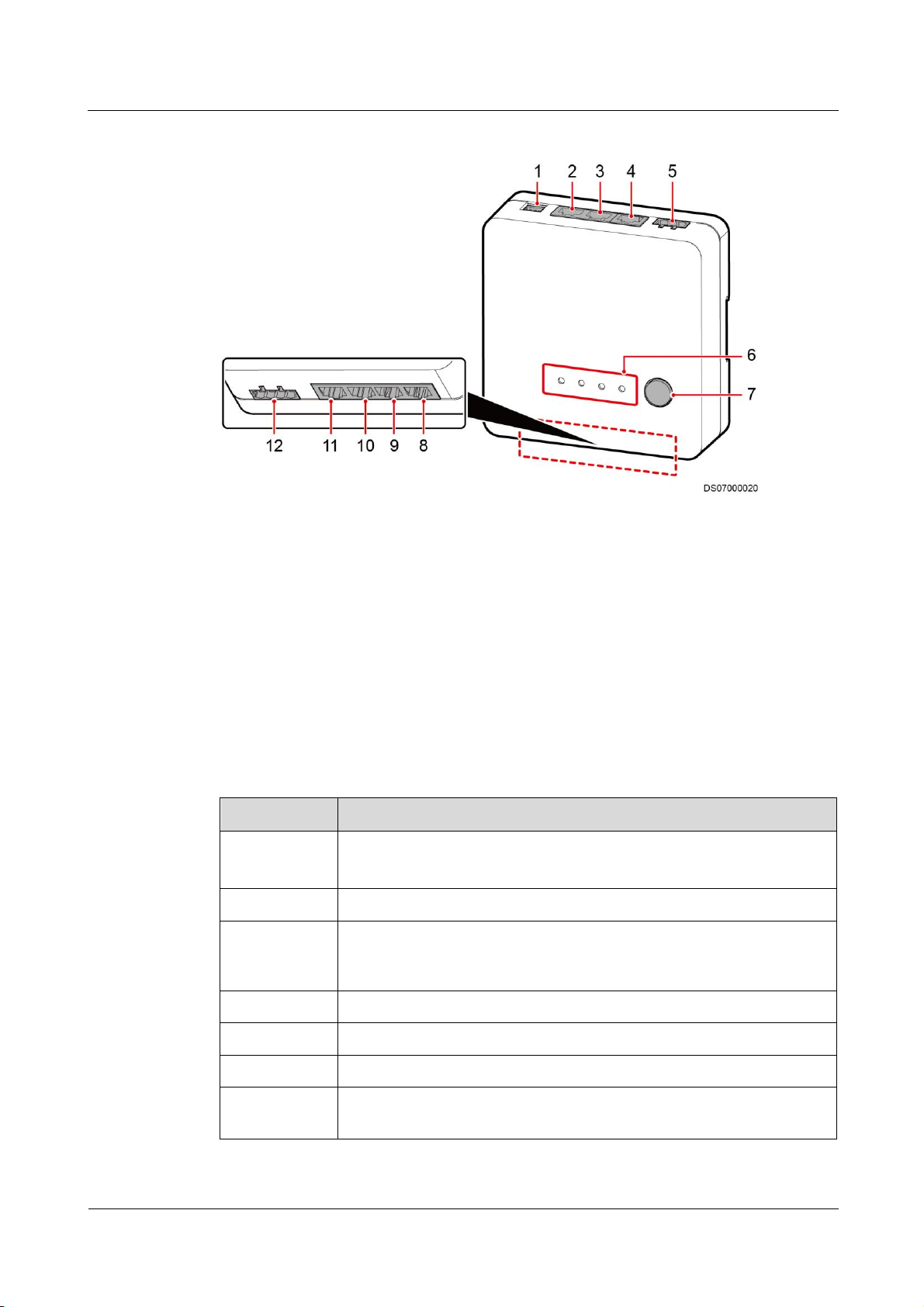
ECC800 Data Center Controller
User Manual
3 Device Description
Issue 02 (2019-02-28)
Copyright © Huawei Technologies Co., Ltd.
31
Figure 3-10 Access actuator
(1) 48 V power port
(2) PoE port
(3) RS485 port COM2
(4) RS485 port COM1
(5) Address DIP switch
(6) Status indicator
(7) BLINK button
(8) WG_2 Wiegand
interface
(9) WG_1 Wiegand interface
(10) AI/DI_2 dry
contact
(11) AI/DI_1 dry
contact
(12) LOCK/GND/GATE/GND/door
status or magnetic lock port
Item
Specifications
Power input
DC input: Terminal, with input voltage of 36–60 V DC
PoE input: One PoE port that complies with IEEE802.3at.
PoE port
FE communication, 10/100M communications rate
Wireless
communicatio
n
One wireless communication port that complies with IEEE802.15.4,
mutual backup with FE communication
AI/DI port
Two AI/DI ports, can connect to the fire alarm and exit button
DO output
One 12 V DC power output that controls magnetic locks, terminal
DI input
One DI input port for connecting to the door status switch
RS485 serial
port expansion
Two RS485 ports (one route) with the default communications rate of
9600 bit/s, physical port cascading supported (reserved function)
Specifications
Table 3-26 Access actuator technical specifications
Page 41

ECC800 Data Center Controller
User Manual
3 Device Description
Issue 02 (2019-02-28)
Copyright © Huawei Technologies Co., Ltd.
32
Item
Specifications
Wiegand
interface
Two Wiegand interfaces, 12 V DC card reader operating power output;
two routes of card readers can operate at the same time.
BLINK button
Press the button for less than 1 second to start blinking.
Hold down the button for 1–5 seconds to search for a network and
start networking.
Hold down the button for more than 6 seconds to clear network
parameters.
Address DIP
switch
4-pin address DIP switch
E-label
Supported
Indicators
Indicator
Color
Name
Status
PWR
Green
Power input status
indicator
Steady on: The power
input is normal.
Off: There is no
power input.
Table 3-27 Access actuator indicator description
Page 42

ECC800 Data Center Controller
User Manual
3 Device Description
Issue 02 (2019-02-28)
Copyright © Huawei Technologies Co., Ltd.
33
Indicator
Color
Name
Status
RUN
Green
Communication status
indicator
Off: The power is
abnormal or the
board program is
loading.
Blinking at long
intervals: The access
actuator successfully
registers with the
ECC800 and the
software runs
properly (the
indicator blinks at 0.5
Hz, on for 1s and
then off for 1s).
Blinking at short
intervals: The
communication is
disconnected or the
access actuator fails
to register with the
ECC800 (the
indicator blinks at 4
Hz, on for 0.125s and
then off for 0.125s).
Blinking: The
indicator blinks at
super short intervals
for 0.5s (blinking at
10 Hz, on for 0.05s
and then off for
0.05s) and then turns
off for 0.5s. The
cycle lasts for 10s.
ALM
Red
Alarm indicator
Steady on: A system
failure alarm is
generated.
Off: No system alarm
is generated.
Page 43

ECC800 Data Center Controller
User Manual
3 Device Description
Issue 02 (2019-02-28)
Copyright © Huawei Technologies Co., Ltd.
34
Indicator
Color
Name
Status
RF_Z
Green
Wireless
communication status
indicator
Steady on: No
network parameters
exist, or a network is
to be created.
Blinking at long
intervals: A network
is set up, and no node
access is allowed (the
indicator blinks at 0.5
Hz, on for 1s and
then off for 1s).
Blinking at super
short intervals: A
network is set up, and
node access is
allowed (the indicator
blinks at 10 Hz, on
for 0.05s and then off
for 0.05s).
Blinking
intermittently at super
short intervals: The
access actuator is
searching for a
network (the
indicator blinks at
super short intervals
for 0.5s and then
turns off for 0.5s).
Item
Description
LOCK/GND
(control
magnetic
locks) pin
sequence
LOCK
12V_OUT
GND
GND
GATE/GND
(door status)
pin sequence
GATE
DI1
GND
GND
Communications Ports
The access actuator provides one DO port (LOCK/GND) and one DI port (GATE/GND).
Table 3-28 lists the LOCK/GND/GATE/GND port pin definitions.
Table 3-28 LOCK/GND/GATE/GND port pin definitions
Page 44
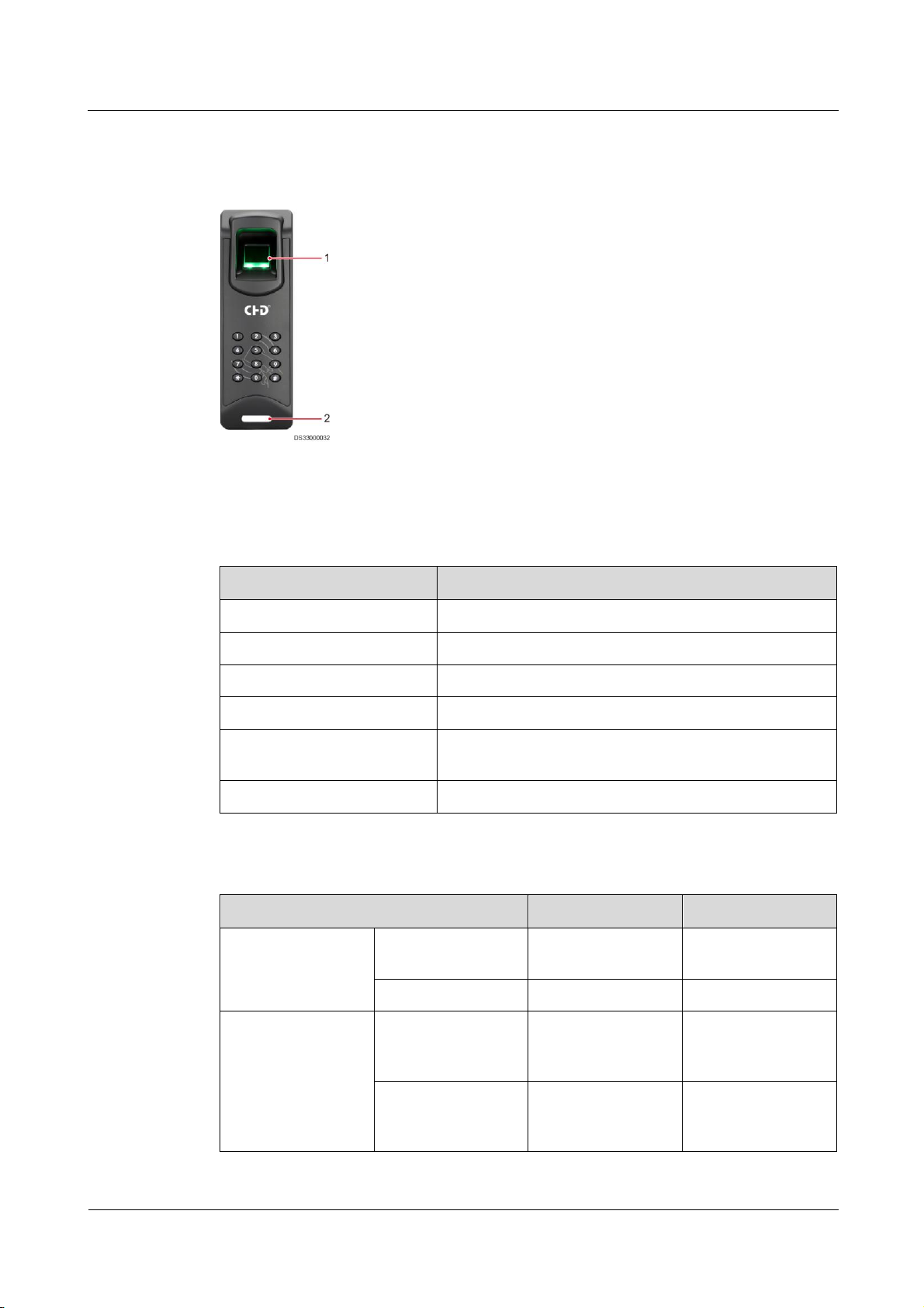
ECC800 Data Center Controller
User Manual
3 Device Description
Issue 02 (2019-02-28)
Copyright © Huawei Technologies Co., Ltd.
35
3.3.5.1.2 Fingerprint and Card Reader with a Keypad
(1) Fingerprint reader
(2) LED indicator
Item
Specifications
Dimensions (L x W x H)
156 mm x 53 mm x 38 mm
Rated operating voltage
12 V DC ± 15%
Rated operating current
300 mA ± 15%
Card type supported
IC card
Authorized storage
A maximum of 3000 authorized users, with a maximum
of 6000 fingerprints
Communications mode
RS485 and Wiegand communications ports
Item
Old Version
New Version
Standby
LED indicator
The indicator is
steady blue.
The indicator is
steady blue.
Fingerprint reader
The indicator is off.
The indicator is off.
Unauthorized
fingerprint
collection
LED indicator
The indicator blinks
blue, red, blue, red,
and blue in order.
The indicator blinks
blue, red, blue, red,
and blue in order.
Fingerprint reader
The indicator blinks
white twice and then
turns on (red).
The indicator turns
on (white).
Figure 3-11 Fingerprint and card reader with a keypad
Table 3-29 Specifications for the fingerprint and card reader with a keypad
Table 3-30 Access control device operating status
Page 45
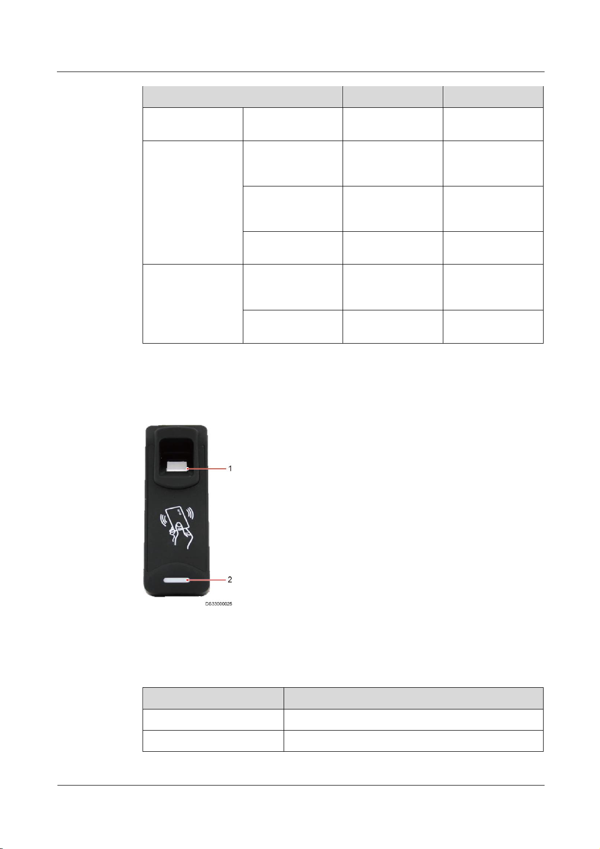
ECC800 Data Center Controller
User Manual
3 Device Description
Issue 02 (2019-02-28)
Copyright © Huawei Technologies Co., Ltd.
36
Item
Old Version
New Version
Buzzer sounds
The buzzer sounds
three.
The buzzer sounds
three.
Authorized
fingerprint
collection
LED indicator
The indicator blinks
blue, red, and blue
in order.
The indicator blinks
blue, red, and blue
in order.
Fingerprint reader
The indicator blinks
white twice and then
turns on (blue).
The indicator turns
on (white).
Buzzer sounds
The buzzer sounds
once.
The buzzer sounds
once.
Card swiping
LED indicator
The indicator blinks
blue, red, and blue
in order.
The indicator blinks
blue, red, and blue
in order.
Buzzer sounds
The buzzer sounds
once.
The buzzer sounds
once.
(1) Fingerprint reader
(2) LED indicator
Item
Specifications
Dimensions (L x W x H)
156 mm x 53 mm x 38 mm
Rated operating voltage
12 V DC ± 5%
3.3.5.1.3 Fingerprint and Card Reader
Figure 3-12 Fingerprint and card reader
Table 3-31 Fingerprint and card reader
Page 46

ECC800 Data Center Controller
User Manual
3 Device Description
Issue 02 (2019-02-28)
Copyright © Huawei Technologies Co., Ltd.
37
Item
Specifications
Rated operating current
300 mA ± 5%
Card type supported
IC card
Authorized storage
A maximum of 3000 authorized users, with a maximum
of 6000 fingerprints
Communications mode
RS485 and Wiegand communications ports
Item
Old Version
New Version
Standby
LED indicator
The indicator is
steady blue.
The indicator is
steady blue.
Fingerprint reader
The indicator is off.
The indicator is off.
Unauthorized
fingerprint
collection
LED indicator
The indicator blinks
blue, red, blue, red,
and blue in order.
The indicator blinks
blue, red, blue, red,
and blue in order.
Fingerprint reader
The indicator blinks
white twice and then
turns on (red).
The indicator turns
on (white).
Buzzer sounds
The buzzer sounds
three.
The buzzer sounds
three.
Authorized
fingerprint
collection
LED indicator
The indicator blinks
blue, red, and blue
in order.
The indicator blinks
blue, red, and blue
in order.
Fingerprint reader
The indicator blinks
white twice and then
turns on (blue).
The indicator turns
on (white).
Buzzer sounds
The buzzer sounds
once.
The buzzer sounds
once.
Card swiping
LED indicator
The indicator blinks
blue, red, and blue
in order.
The indicator blinks
blue, red, and blue
in order.
Buzzer sounds
The buzzer sounds
once.
The buzzer sounds
once.
Table 3-32 Access control device operating status
Page 47
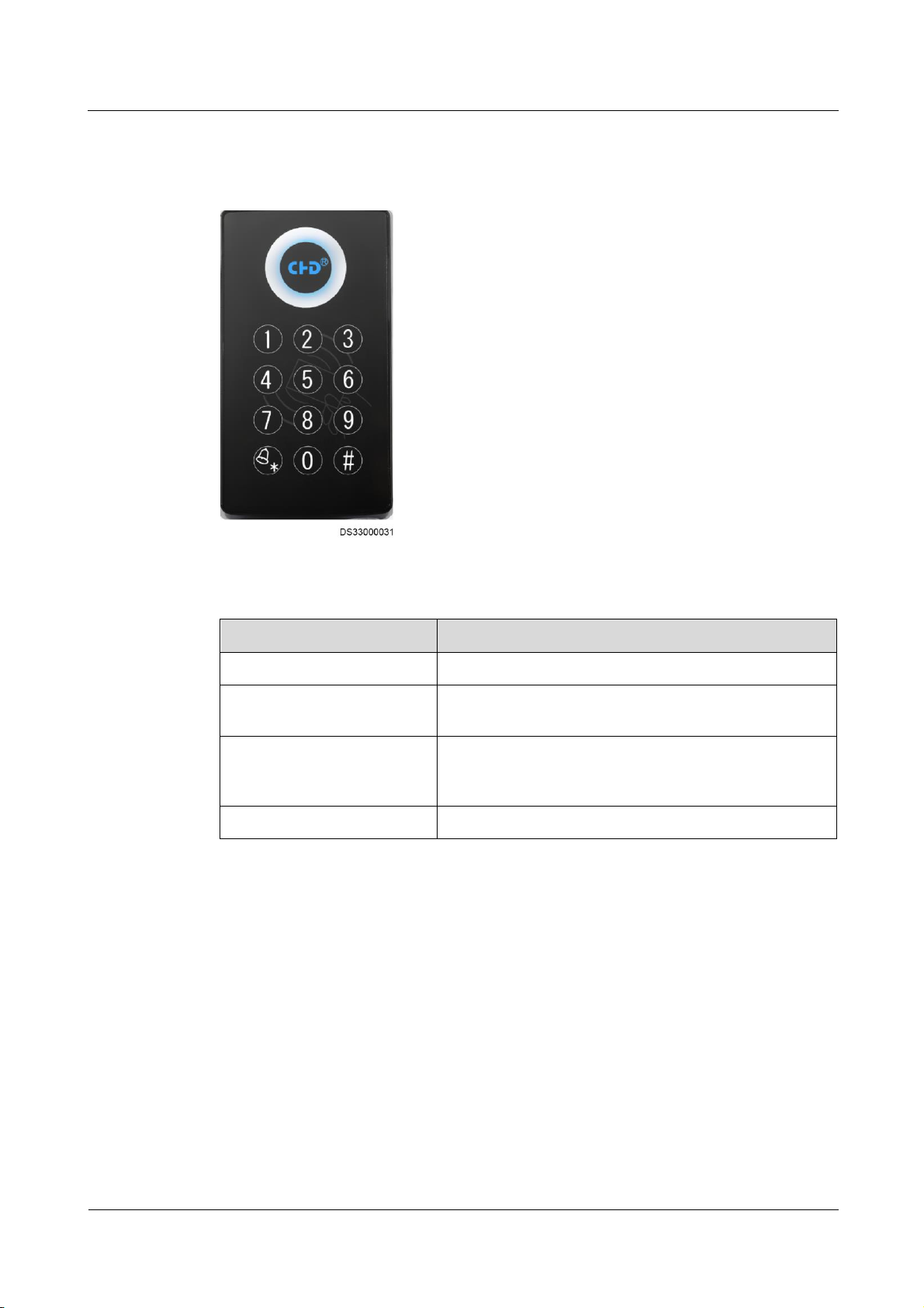
ECC800 Data Center Controller
User Manual
3 Device Description
Issue 02 (2019-02-28)
Copyright © Huawei Technologies Co., Ltd.
38
3.3.5.1.4 Card Reader with a Keypad
Item
Specifications
Dimensions (L x W x H)
114 mm x 63 mm x 25 mm
Operating voltage
Operating voltage range: 10.8–13.2 V DC; rated voltage:
12 V DC
Operating current
Static standby current 80 mA, dynamic operating current
(card swiping, key pressing) 150 mA, minimum input
current 12 V DC/300 mA
Communications mode
Wiegand communications port
Figure 3-13 Card reader with a keypad
Table 3-33 Specifications of a card reader with a keypad
Page 48
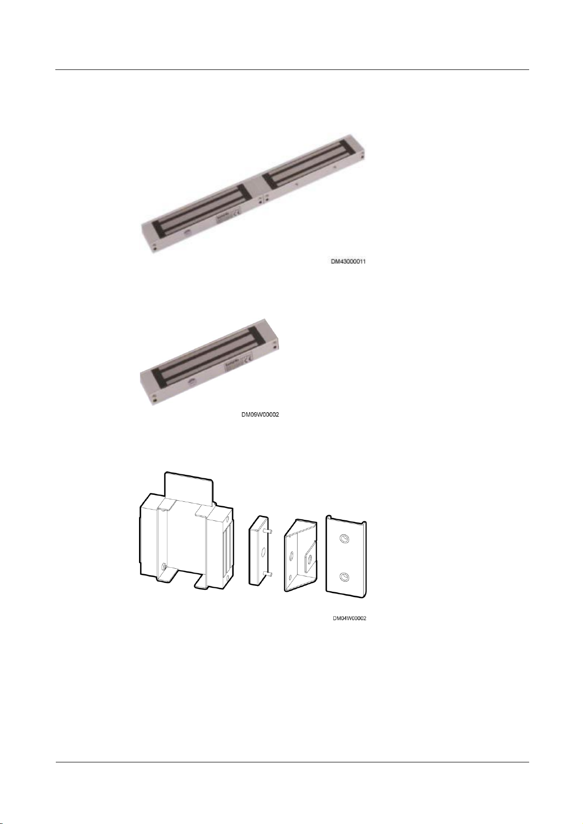
ECC800 Data Center Controller
User Manual
3 Device Description
Issue 02 (2019-02-28)
Copyright © Huawei Technologies Co., Ltd.
39
3.3.5.1.5 Magnetic Lock
Figure 3-14 Double door magnetic lock
Figure 3-15 Single door magnetic lock
Figure 3-16 Magnetic lock for a sliding door
3.3.5.2 Cabinet Access Control System
The cabinet access control system applies to cabinets in the aisle containment to ensure data
and device security.
Page 49

ECC800 Data Center Controller
User Manual
3 Device Description
Issue 02 (2019-02-28)
Copyright © Huawei Technologies Co., Ltd.
40
Electronic cabinet lock
Item
Specifications
Rated input voltage
12 V DC
Rated current
200–300 mA
Unlock mode
Power on to unlock
Card type supported
IC card
Mechanically unlock
Supported
Features:
An IC card can be used after being authorized using software.
An IC card can be authorized for one lock or all locks.
Door opening information is recorded through a network.
The system displays the status of cabinet doors and locks in real time, the system
displays the status of cabinet doors and locks in real time and reports the unauthorized
door opening.
The system supports remote unlocking.
Figure 3-17 Electronic cabinet lock
Table 3-34 Cabinet electronic lock specifications
Mechanical Code Lock
Features:
The cabinet door can be opened with only the key and without the password.
The cabinet door can be opened with only the password and without the key.
The user can set a password.
A password should contain at least three digits.
The password can be reset if the user forgot it.
Page 50
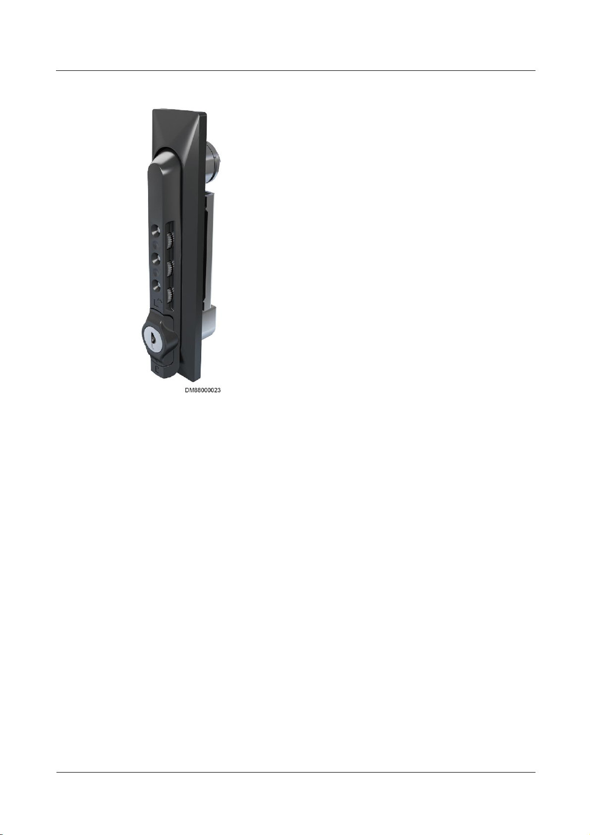
ECC800 Data Center Controller
User Manual
3 Device Description
Issue 02 (2019-02-28)
Copyright © Huawei Technologies Co., Ltd.
41
Figure 3-18 Mechanical code lock
3.3.6 AC Actuator
The AC actuator is used in a smart module to control the lighting inside the smart module by
receiving commands from the access control system or host, infrared linkage information
(disabled by default), or signals from the light button. It also provides a charging port for the
pad.
Page 51
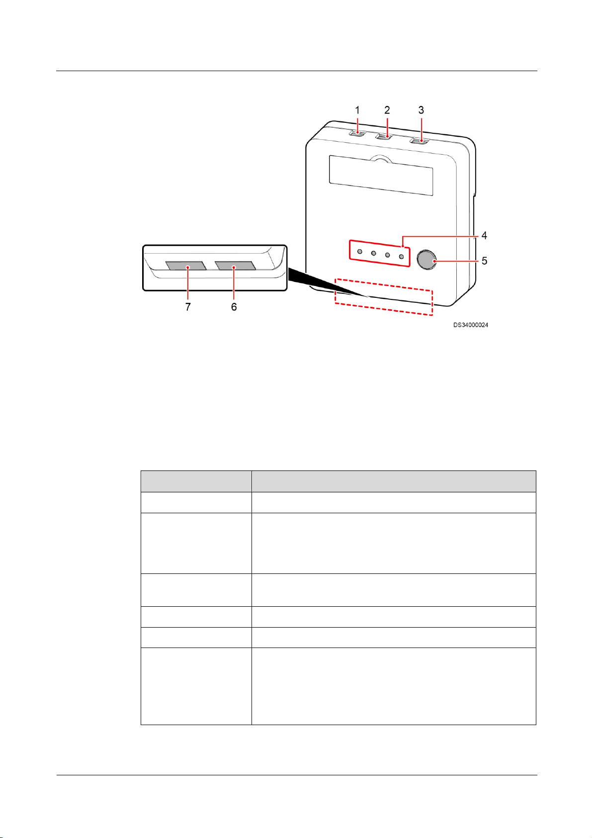
ECC800 Data Center Controller
User Manual
3 Device Description
Issue 02 (2019-02-28)
Copyright © Huawei Technologies Co., Ltd.
42
Figure 3-19 AC actuator
(1) AC OUT2 port
(2) AC OUT1 port
(3) AC IN port
(4) Status indicator
(5) BLINK button
(6) AI/DI dry
contact
(7) COM1–2 RS485
port
Item
Specifications
Power input
One AC input, 100–240 V AC.
Power output
AC OUT1: two AC outputs, 100–240 V AC, maximum total
current: 5 A.
AC OUT2: one AC output, 100–240 V AC, maximum
current: 5 A.
Wireless
communication
One wireless communication port, complying with
IEEE802.15.4.
RS485 port
One route of dual RS485 ports, not isolated (reserved).
AI/DI detection
Two AI/DI dry contacts, connecting to two light buttons.
BLINK button
Press the button for less than 1 second to start blinking.
Hold down the button for 1–5 seconds to search for a network
and start networking.
Hold down the button for more than 10 seconds to clear
network parameters.
Specifications
Table 3-35 AC actuator technical specifications
Page 52

ECC800 Data Center Controller
User Manual
3 Device Description
Issue 02 (2019-02-28)
Copyright © Huawei Technologies Co., Ltd.
43
Indicators
Indicator
Color
Name
Status
Description
Power
Green
Power status
indicator
Steady on
The power input is normal.
Off
There is no power input.
RUN
Green
Running
status
indicator
Off
The power is abnormal or the
board program is loading.
Blinking at
long intervals
The AC actuator successfully
registers with the ECC800 and
the software runs properly (the
indicator blinks at 0.5 Hz, on
for 1s and then off for 1s).
Blinking at
short intervals
The communication is
disconnected or the AC
actuator fails to register with
the ECC800 (the indicator
blinks at 4 Hz, on for 0.125s
and then off for 0.125s).
Blinking
The indicator blinks at super
short intervals for 0.5s
(blinking at 10 Hz, on for
0.05s and then off for 0.05s)
and then turns off for 0.5s. The
cycle lasts for 10s.
ALM
Red
Alarm
indicator
Steady on
A system failure alarm is
generated.
Off
No system alarm is generated.
RF_Z
Green
Communicati
on status
indicator
Steady on
No network parameters exist,
or a network is to be created.
Blinking at
long intervals
A network is set up, and no
node access is allowed (the
indicator blinks at 0.5 Hz, on
for 1s and then off for 1s).
Blinking at
super short
intervals
A network is set up, and node
access is allowed (the indicator
blinks at 10 Hz, on for 0.05s
and then off for 0.05s).
Blinking
intermittently
at super short
intervals
The AC actuator is searching
for a network (the indicator
blinks at super short intervals
for 0.5s and then turns off for
0.5s).
Table 3-36 AC actuator indicators
Page 53
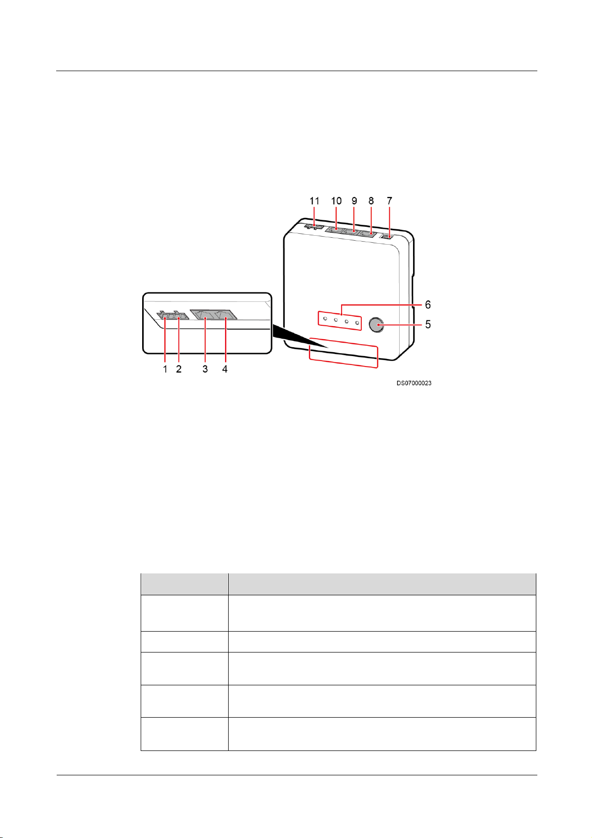
ECC800 Data Center Controller
User Manual
3 Device Description
Issue 02 (2019-02-28)
Copyright © Huawei Technologies Co., Ltd.
44
3.3.7 Skylight Actuator
(1) LOCK/GND
magnetic lock DO
output port
(2) BUTTON/GND
window open button
DI input port
(3) AI/DI_1 sensor
input port
(4) AI/DI_2 sensor
input port
(5) BLINK button
(6) Status indicator
(7) Address DIP
switch
(8) COM1 port
(9) COM2 port
(10) PoE port
(11) 48 V power port
Item
Specifications
Power input
DC input: Terminal, with input voltage of 36–60 V DC
PoE input: One PoE port that complies with IEEE802.3at.
PoE port
FE communication with the rate of 10/100M
Wireless
communication
One wireless port that complies with IEEE802.15.4, mutual backup
with FE communication
AI/DI port
Two AI/DI ports for detecting fire extinguishing linkage signals;
smoke detection signals also supported
DO output
One 12 V DC power output for controlling the skylight magnetic lock;
driving six skylight magnetic locks simultaneously
The skylight actuator controls the rotating skylight on the aisle containment of the smart
module through the alarm linkage information from the fire extinguishing system or the
control information from the upper computer. The skylight actuator supports E-labels and
wireless networking (802.15.4).
Figure 3-20 Skylight actuator
Specifications
Table 3-37 Skylight actuator technical specifications
Page 54

ECC800 Data Center Controller
User Manual
3 Device Description
Issue 02 (2019-02-28)
Copyright © Huawei Technologies Co., Ltd.
45
Item
Specifications
DI input
One DI input port for connecting to the window open button
BLINK button
Hold down the button for less than 1 second to start blinking.
Hold down the button for 1–5 seconds to search for a network and
start networking.
Hold down the button for more than 6 seconds to clear network
parameters.
Address DIP
switch
4-pin address DIP switch
E-label
Supported
Indicators
Indicator
Color
Name
Status
Description
Power
Green
Power input
status indicator
Steady on
The power input is normal.
Off
There is no power input.
RUN
Green
Operating
status indicator
Off
The power is abnormal or the
board program is loading.
Blinking at
long intervals
The skylight actuator
successfully registers with the
ECC800 and the software runs
properly (the indicator blinks at
0.5 Hz, on for 1s and then off for
1s).
Blinking at
short intervals
The communication fails or the
skylight actuator fails to register
with the ECC800 (the indicator
blinks at 4 Hz, on for 0.125s and
then off for 0.125s).
Blinking
The indicator blinks at super
short intervals for 0.5s (blinking
at 10 Hz, on for 0.05s and then
off for 0.05s) and then turns off
for 0.5s. The cycle lasts for 10s.
ALM
Red
Alarm
indicator
Steady on
A system failure alarm is
generated.
Off
No system alarm is generated.
RF_Z
Green
Communicatio
n status
Steady on
No network parameters exist, or
a network is to be created.
Table 3-38 Skylight actuator indicator description
Page 55
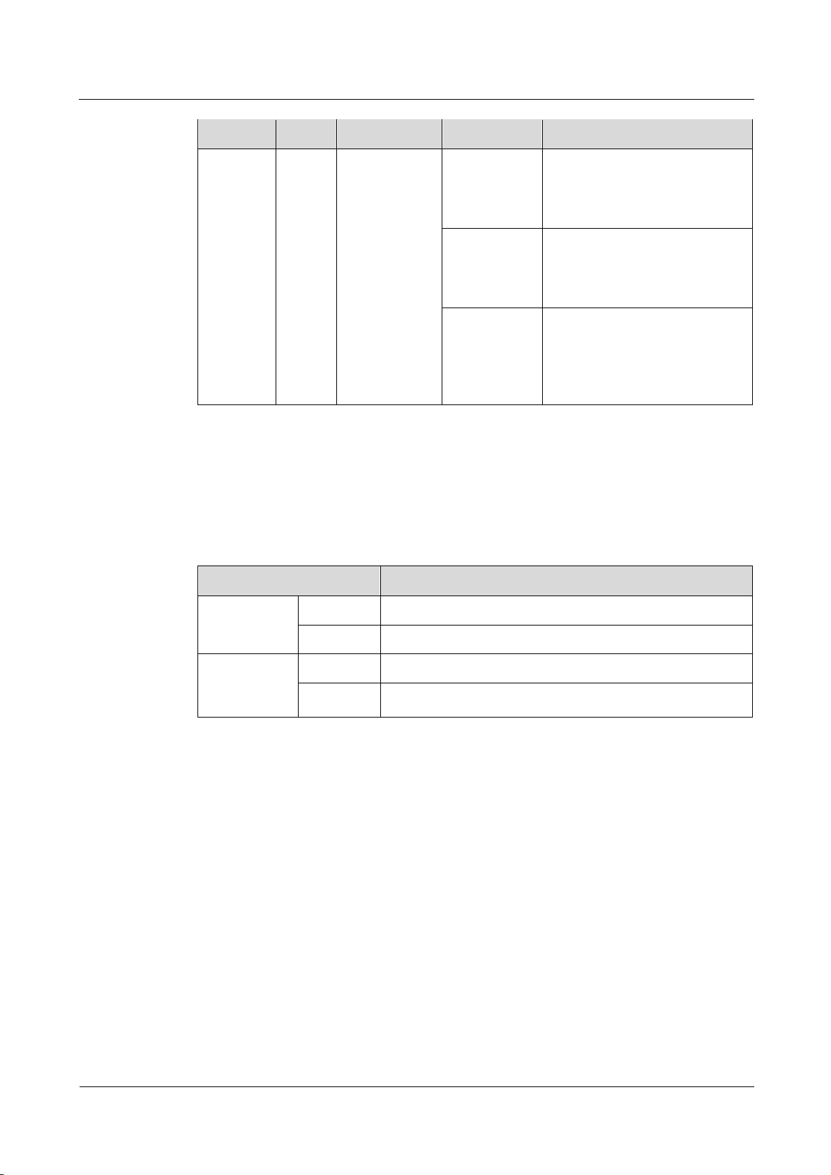
ECC800 Data Center Controller
User Manual
3 Device Description
Issue 02 (2019-02-28)
Copyright © Huawei Technologies Co., Ltd.
46
Indicator
Color
Name
Status
Description
indicator
Blinking at
long intervals
A network is set up, and no node
access is allowed (the indicator
blinks at 0.5 Hz, on for 1s and
then off for 1s).
Blinking at
super short
intervals
A network is set up, and node
access is allowed (the indicator
blinks at 10 Hz, on for 0.05s and
then off for 0.05s).
Blinking
intermittently
at super short
intervals
The skylight actuator is
searching for a network (the
indicator blinks at super short
intervals for 0.5s and then turns
off for 0.5s).
Item
Description
LOCK/GND
pin sequence
LOCK
12V_OUT
GND
GND
BUTTON/GN
D pin
sequence
BUTTON
DI3
GND
GND
Communications Ports
The skylight actuator provides one DO port (LOCK/GND) and one DI port (BUTTON/GND).
Table 3-39 lists the LOCK/GND/BUTTON/GND port pin definitions.
Table 3-39 LOCK/GND/BUTTON/GND port pin definitions
3.3.8 Multi-Functional Sensor
A multi-functional sensor integrates the temperature and humidity (T/H) sensor and smoke
sensor. The multi-functional sensor can connect to the ECC800 over FE or wireless
communication.
Page 56
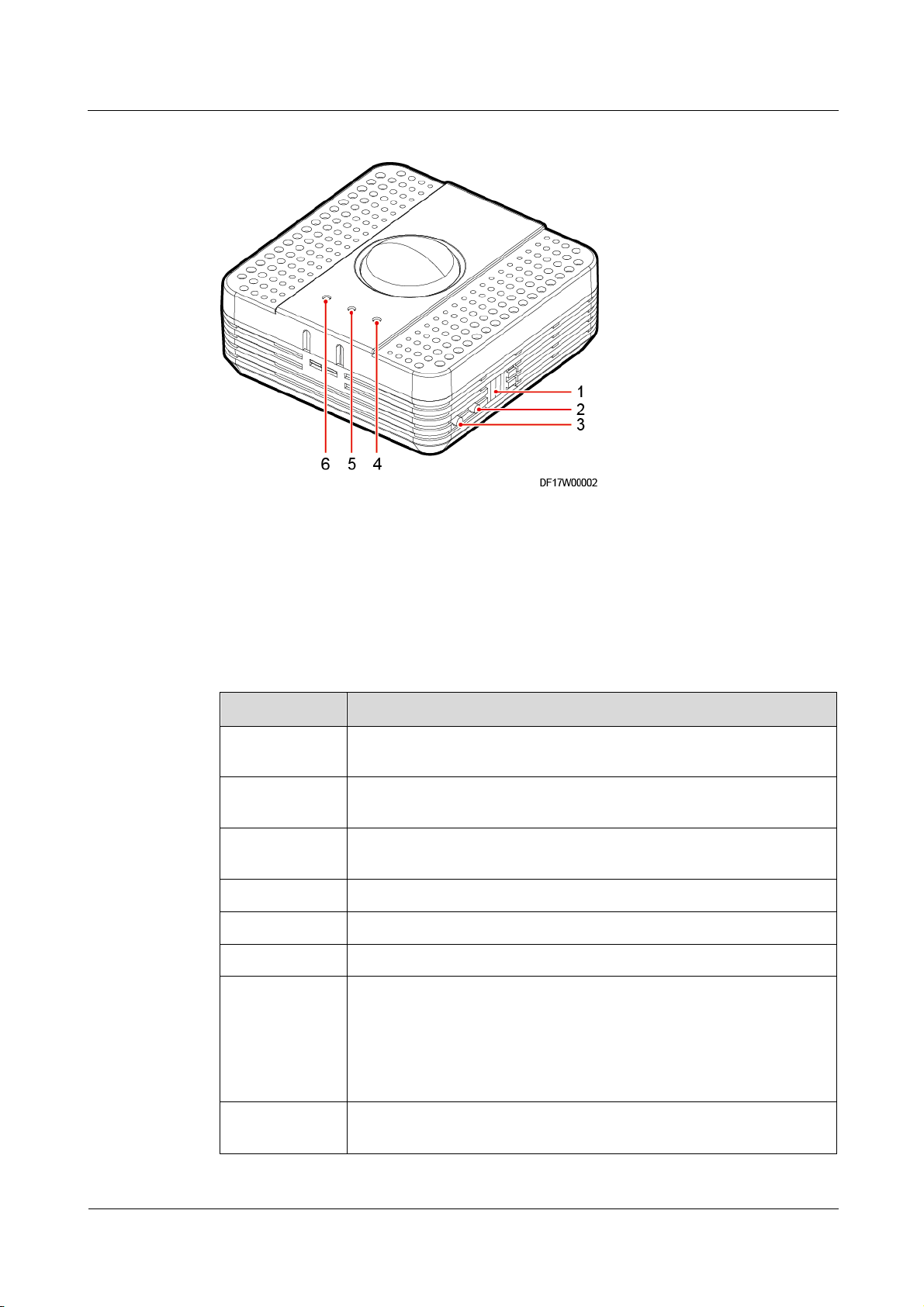
ECC800 Data Center Controller
User Manual
3 Device Description
Issue 02 (2019-02-28)
Copyright © Huawei Technologies Co., Ltd.
47
Figure 3-21 Multi-functional sensor
(1) Address DIP switch
(2) BLINK button
(3) TEST button
(4) RF_Z indicator
(5) RUN indicator
(6) ALM indicator
Item
Specifications
Temperature
monitoring
–40°C to 80°C.
Humidity
monitoring
Precision ≤ ±5% RH (25°C, 20%–80% RH).
Smoke
monitoring
Complies with Ul217. The smoke sensor generates an alarm when
testing 3.2% weak dust for each foot.
PoE port
One PoE port that complies with IEEE802.3at.
RS485 port
Reserves one RS485 port.
DI input
One DI input port, 12 V DC power input.
BLINK button
Wireless communication:
Press the button for less than 1 second to start blinking.
Hold down the button for 1–5 seconds to search for a network and
start networking.
Hold down the button for more than 6s to clear network parameters.
Smoke sensor
test button
Supported
Specifications
Table 3-40 Multi-functional sensor technical specifications
Page 57

ECC800 Data Center Controller
User Manual
3 Device Description
Issue 02 (2019-02-28)
Copyright © Huawei Technologies Co., Ltd.
48
Item
Specifications
E-label
Supported
Indicators
Indicator
Color
Name
Status
Description
RUN
Green
Module
running status
indicator
Blinking at
long
intervals
The multi-functional sensor
successfully registers with
the ECC800 and the software
runs properly (the indicator
blinks at 0.5 Hz, on for 1s
and then off for 1s).
Blinking at
short
intervals
The multi-functional sensor
fails to register with the
ECC800 or the
communication fails (the
indicator blinks at 4 Hz, on
for 0.125s and then off for
0.125s).
Blinking
The indicator blinks at super
short intervals for 0.5s
(blinking at 10 Hz, on for
0.05s and then off for 0.05s)
and then turns off for 0.5s.
The cycle lasts for 10s.
ALM
Red
Alarm
indicator
Steady on
A system failure alarm or
smoke alarm is generated.
Off
No system alarm is
generated.
RF_Z
Green
Communicati
on status
indicator
Steady on
No network parameters exist,
or a network is to be created.
Blinking at
long
intervals
A network is set up, and no
node access is allowed (the
indicator blinks at 0.5 Hz, on
for 1s and then off for 1s).
Blinking at
super short
intervals
A network is set up, and
node access is allowed (the
indicator blinks at 10 Hz, on
for 0.05s and then off for
0.05s).
Table 3-41 Description of the indicators on the multi-functional sensor
Page 58
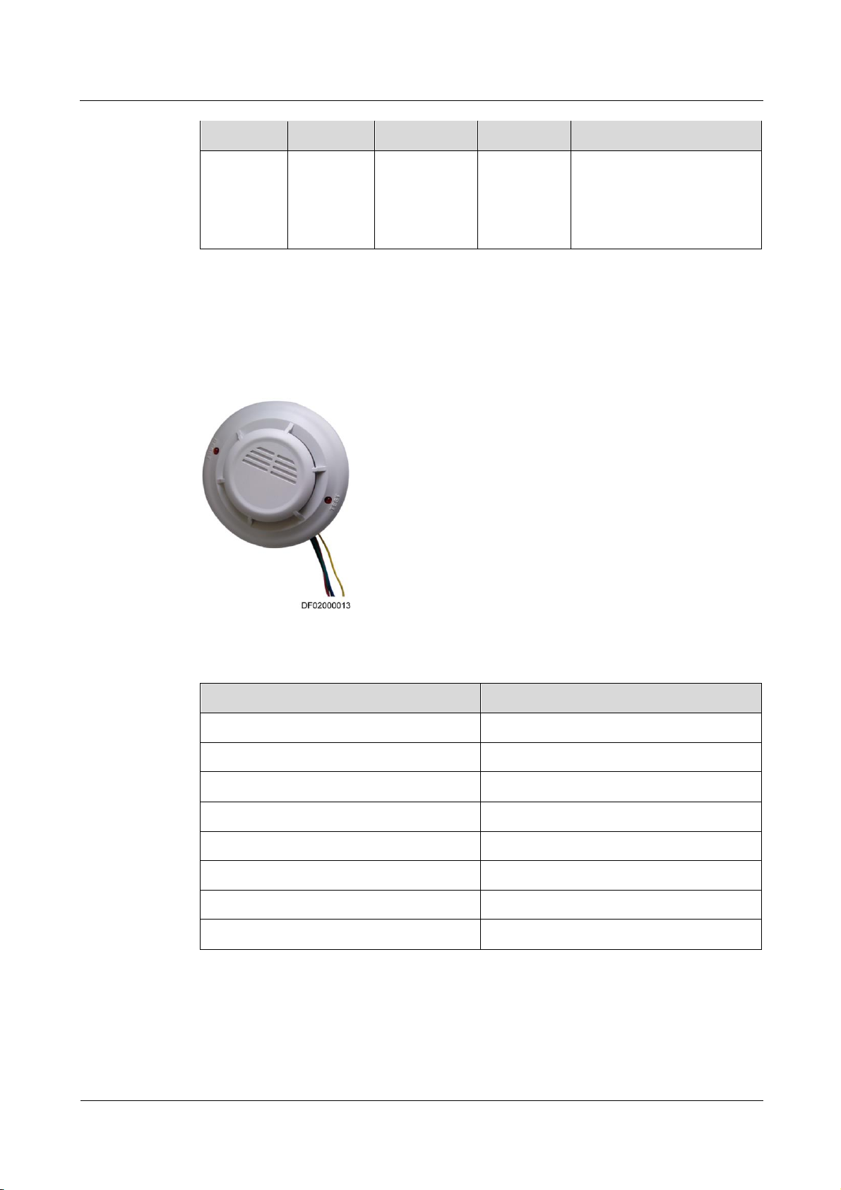
ECC800 Data Center Controller
User Manual
3 Device Description
Issue 02 (2019-02-28)
Copyright © Huawei Technologies Co., Ltd.
49
Indicator
Color
Name
Status
Description
Blinking
intermittentl
y at super
short
intervals
The multi-functional sensor
is searching for a network
(the indicator blinks at super
short intervals for 0.5s and
then turns off for 0.5s).
Item
Specifications
Operating voltage
DC12V (9–16 V DC)
Quiescent current
< 8 mA
Alarm current
< 35 mA
Output mode
Relay output
Output contact capacity
3 A/120 V AC or 3 A/24 V AC
Operating temperature
–10ºC to +50ºC
Ambient humidity
< 95% RH (non-condensing)
Dimensions
Diameter: 112 mm, height: 41 mm
3.3.9 Smoke Detector
Smoke detectors are used to detect the smoke concentration.
Figure 3-22 Smoke detector
Table 3-42 Technical specifications of a smoke detector
3.3.10 Temperature Sensor
The temperature sensor (the code: 33010348) is used for the surface temperature measure,
industrial process control, measurement instrument, etc.
Page 59
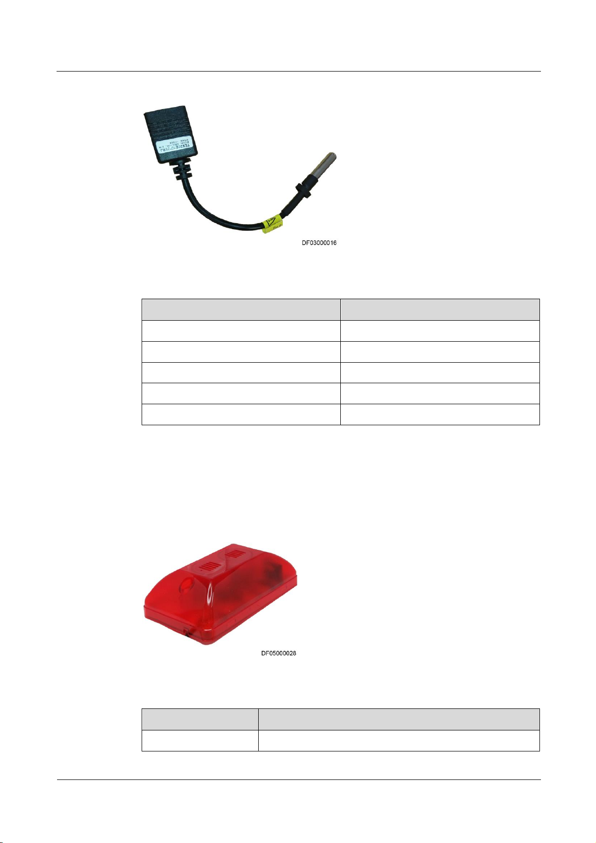
ECC800 Data Center Controller
User Manual
3 Device Description
Issue 02 (2019-02-28)
Copyright © Huawei Technologies Co., Ltd.
50
Figure 3-23 Temperature sensor
Item
Specifications
Measurement range
–20ºC to +70ºC
Measurement precision
±1ºC (25°C)
Operating temperature
–10ºC to +55ºC
Operating voltage
10–16 V DC
Storage temperature
–40ºC to +70ºC
Item
Specifications
Dimensions (L x W x H)
130 mm x 75 mm x 55 mm
Table 3-43 Temperature sensor specifications
3.3.11 Alarm Beacon
When a fire occurs or smokes are generated in the micro-modular equipment room, the alarm
beacon generates an audible signal and flashes to inform operators of fire and security risks.
Figure 3-24 Alarm beacon
Table 3-44 Structural specifications of an alarm beacon
Page 60
ECC800 Data Center Controller
User Manual
3 Device Description
Issue 02 (2019-02-28)
Copyright © Huawei Technologies Co., Ltd.
51
Item
Specifications
Installation requirements
Installed on a wall
Protection level
IP50
Environmental
requirements
RoHS, Reach
Item
Specifications
Power input
RJ45 port, input voltage 9–16 V DC, operating current ≤ 400
mA
Sound pressure
≥ 100 ± 3 dB/30 cm
Continuous operating
time
≥ 45 min
Table 3-45 Technical specifications of an alarm beacon
3.3.12 Water Sensor
A water sensor detects water on the floor in real time and generates an alarm when water is
detected.
3.3.12.1 WLDS600 Water Sensor
The WLDS600 water sensor with the BOM number of 33010465 consists of a water detection
cable, a water detector, and a conversion cable.
Page 61
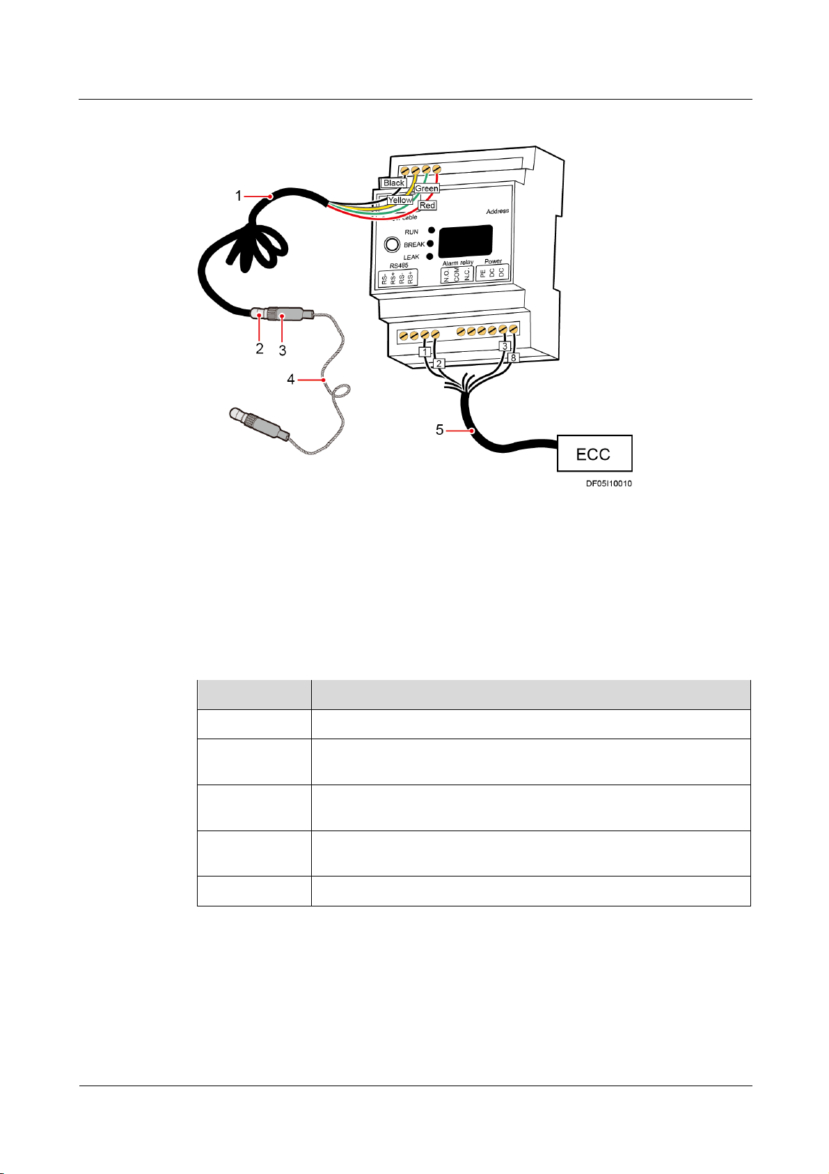
ECC800 Data Center Controller
User Manual
3 Device Description
Issue 02 (2019-02-28)
Copyright © Huawei Technologies Co., Ltd.
52
Figure 3-25 WLDS600 water sensor
(1) Conversion
cable
(2) Conversion cable end B,
connected to the water detection
cable
(3) Water detection cable end A,
connected to the conversion
cable
(4) Water
detection cable
(5) Communications/Power cable
Item
Specification
Detection cable
0–200 m
Operating
voltage
12 V to 24 V DC
Operating
temperature
–20°C to 70°C
Storage
temperature
–20°C to 80°C
Humidity
10%–80% RH (non-condensing)
Table 3-46 WLDS600 water sensor specifications
3.3.12.2 WLDS900 Water Sensor
The WLDS900 water sensor with the BOM number of 33010352 consists of a water detection
cable, a water detector, and a conversion cable.
Page 62
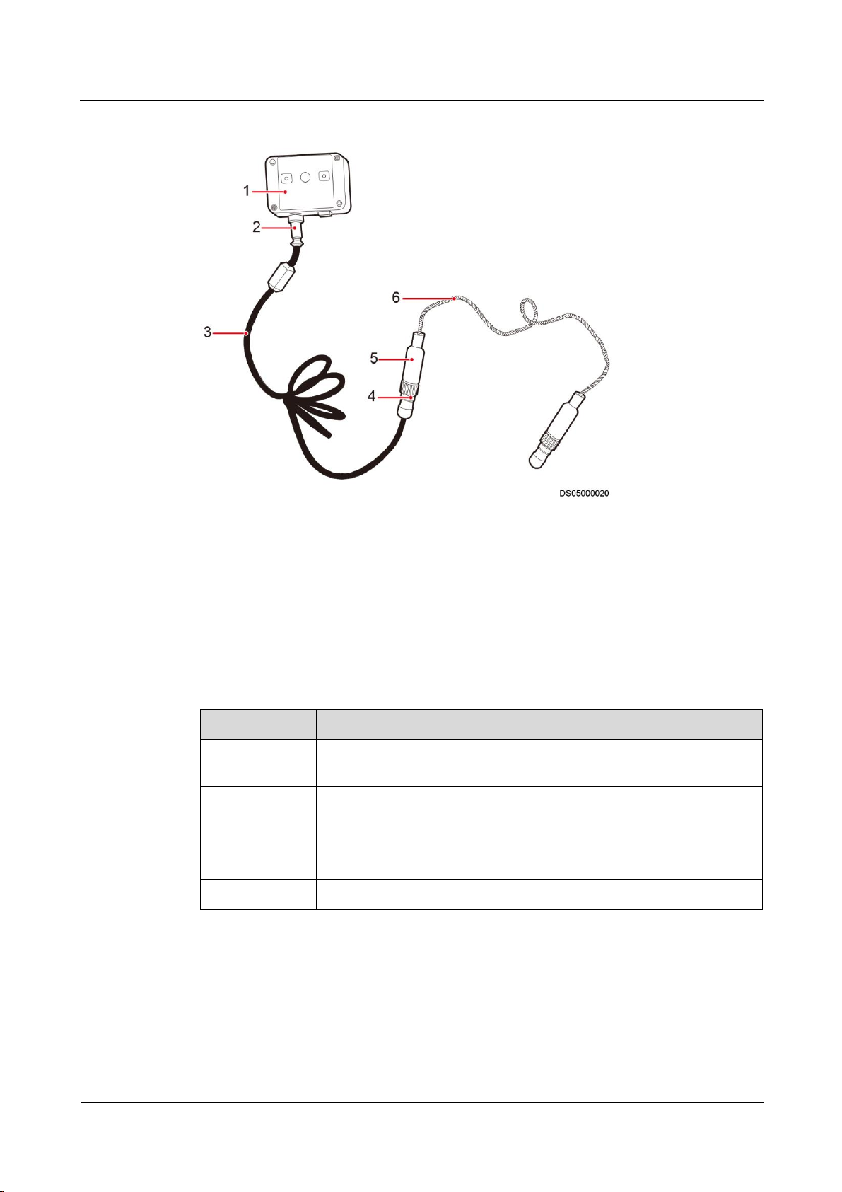
ECC800 Data Center Controller
User Manual
3 Device Description
Issue 02 (2019-02-28)
Copyright © Huawei Technologies Co., Ltd.
53
Figure 3-26 WLDS900 water sensor
(1) Water detector
(2) Conversion cable end A, connected
to the water detector
(3) Conversion cable
(4) Conversion cable
end B, connected to
the water detection
cable
(5) Water detection cable end A,
connected to the conversion cable
(6) Water detection
cable
Item
Specification
Operating
voltage
12 V DC (9–16 V DC)
Operating
temperature
–20°C to +70°C
Storage
temperature
–40°C to +85°C
Humidity
10%–80% RH (non-condensing)
Table 3-47 WLDS900 water sensor specifications
3.3.12.3 Electrode Water Sensor
The electrode water sensor with the BOM number of 33010444 contains electrode probes and
cables.
Page 63
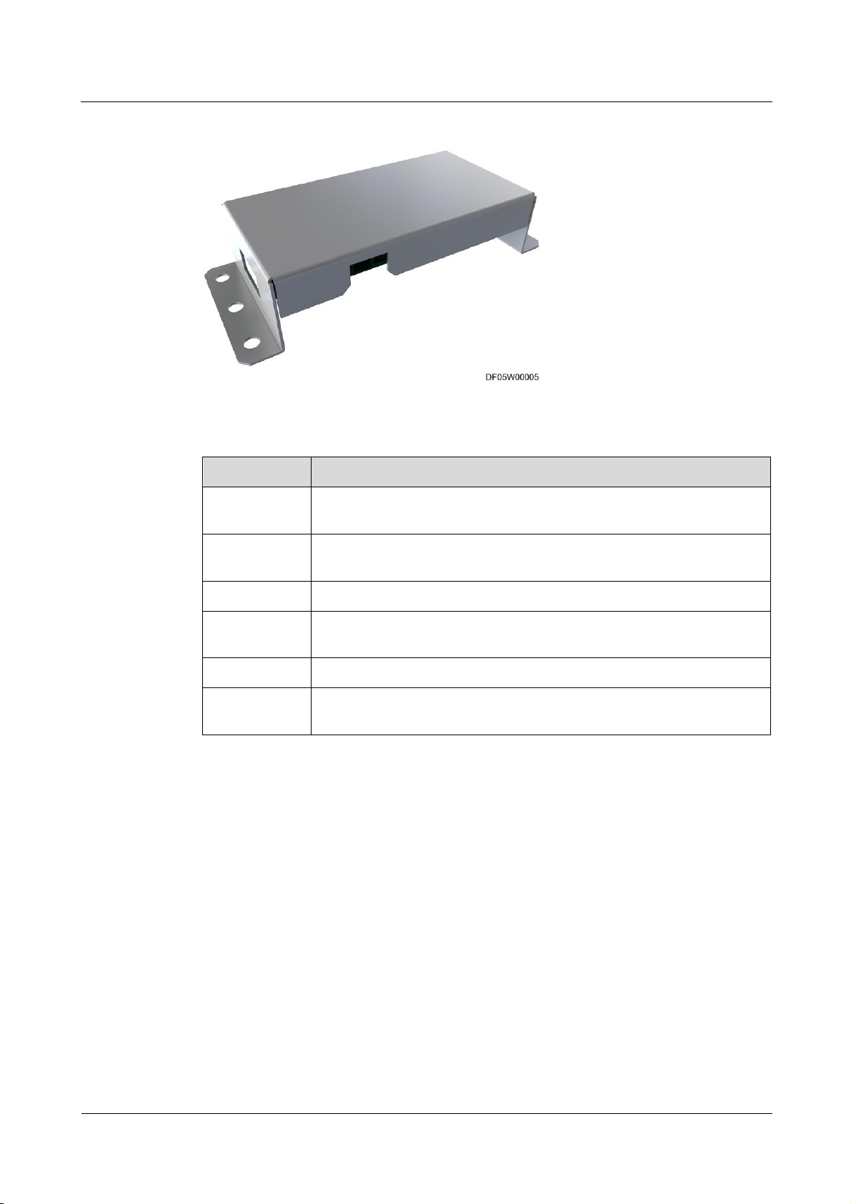
ECC800 Data Center Controller
User Manual
3 Device Description
Issue 02 (2019-02-28)
Copyright © Huawei Technologies Co., Ltd.
54
Figure 3-27 Electrode water sensor
Item
Specification
Operating
temperature
–40°C to +80°C
Storage
temperature
–40°C to +80°C
Humidity
0–100% RH (non-condensing)
Insulation
resistance
> 500 megohms
Reliability test
Failure rate: 800 fits
Power
consumption
< 1 W
Table 3-48 Electrode water sensor technical specifications
3.3.13 WiFi Converter
The WiFi converter is used in a smart module to convert PoE signals into WiFi signals for
communicating with devices such as the pad and mobile phone.
Page 64
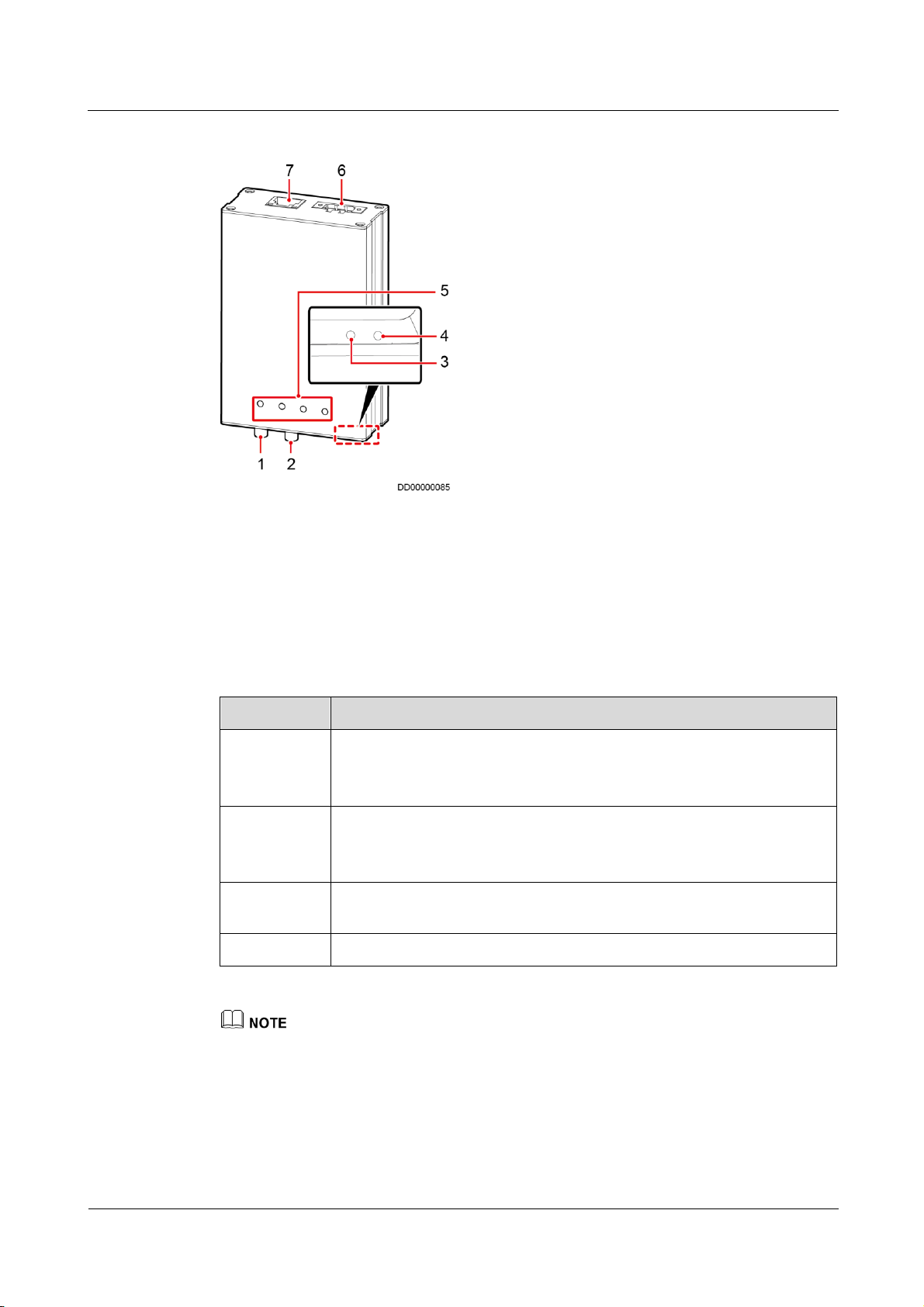
ECC800 Data Center Controller
User Manual
3 Device Description
Issue 02 (2019-02-28)
Copyright © Huawei Technologies Co., Ltd.
55
Figure 3-28 WiFi converter
(1) RF_1 antenna port
(2) RF_2 antenna port
(3) Reset button
(4) WPS button
(5) Status indicator
(6) 48 V power port
(7) PoE port
Item
Specifications
Power input
DC input: Terminal, with input voltage of 36–60 V DC
PoE power supply: One PoE port, complying with IEEE802.3at, 25.5
W
WiFi function
2.4 GHz frequency, two antennas, supporting eight STA connections,
50 m WiFi coverage (no blockage)
Support the WPS button
Reset button
Press and hold down the button for more than 5s to restore the factory
settings of the WiFi converter.
WPS button
Support fast WiFi access by WPS
Specifications
Table 3-49 WiFi converter technical specifications
WPS function: If you choose Advanced settings > WPS connection on the WLAN of the intelligent
device and press the WPS button on the WiFi converter at the same time, the intelligent device will
quickly connect to the WiFi hotspot of the micro-module.
Page 65

ECC800 Data Center Controller
User Manual
3 Device Description
Issue 02 (2019-02-28)
Copyright © Huawei Technologies Co., Ltd.
56
Indicators
Indicator
Color
Name
Status
Description
RUN
Green
Running
status
indicator
Blinking at
long intervals
The WiFi converter
successfully registers with the
ECC800 and the software runs
properly (the indicator blinks
at 0.5 Hz, on for 1s and then
off for 1s).
Blinking at
short intervals
The WiFi converter fails to
register with the ECC800 or
the communication is
disconnected (the indicator
blinks at 4 Hz, on for 0.125s
and then off for 0.125s).
ALM
Red
Alarm
indicator
Steady on
A system failure alarm is
generated.
Off
No system alarm is generated.
WiFi
Green
WiFi status
indicator
Steady on
The WiFi converter is powered
on but there is no data
communication.
Blinking
Data communication is in
progress.
WPS
Green
WPS mode
indicator
Off
The WPS is normal.
Blinking
WPS matching mode. If the
matching fails, the WPS
indicator turns off after
blinking for 2 minutes. If the
matching is successful, the
WPS indicator turns off.
Table 3-50 WiFi converter indicators
3.3.14 WiFi Module
The WiFi module provides WiFi signals for equipment such as pads and mobile phones to
interact with the host computer.
Page 66
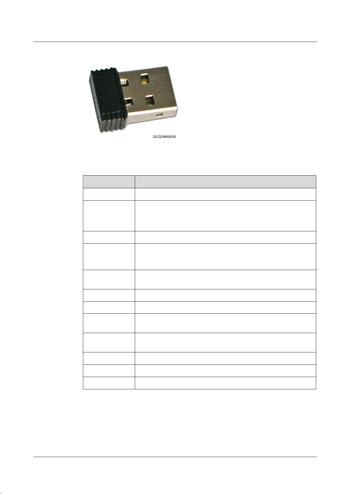
ECC800 Data Center Controller
User Manual
3 Device Description
Issue 02 (2019-02-28)
Copyright © Huawei Technologies Co., Ltd.
57
Figure 3-29 WiFi module
Item
Specifications
Wireless standard
IEEE 802.11n, IEEE 802.11g, and IEEE 802.11b
Network
bandwidth
11n: up to 150 Mbps
11g: up to 54 Mbps
11b: up to 11 Mbps
Frequency band
2.4-2.4835 GHz
Wireless
transmission
power
20 dBm (MAX EIRP)
Supported
operating system
Windows 2000/XP/Vista/Linux/Win 7
Ports
USB 2.0 high-speed connector
Voltage range
5.0 V DC±5%
Operating
temperature
-20°C to +70°C
Storage
temperature
-40°C to +90°C
Relative humidity
10%–90% RH (non-condensing)
Storage humidity
5%–90% RH (non-condensing)
Power
< 0.8 W
Table 3-51 Technical specifications
3.3.15 ETH Converter
The ETH converter is used to convert the Modbus–RTU protocol or CAN protocol to the
Modbus-MAC protocol for connecting to the PoE bus.
Page 67
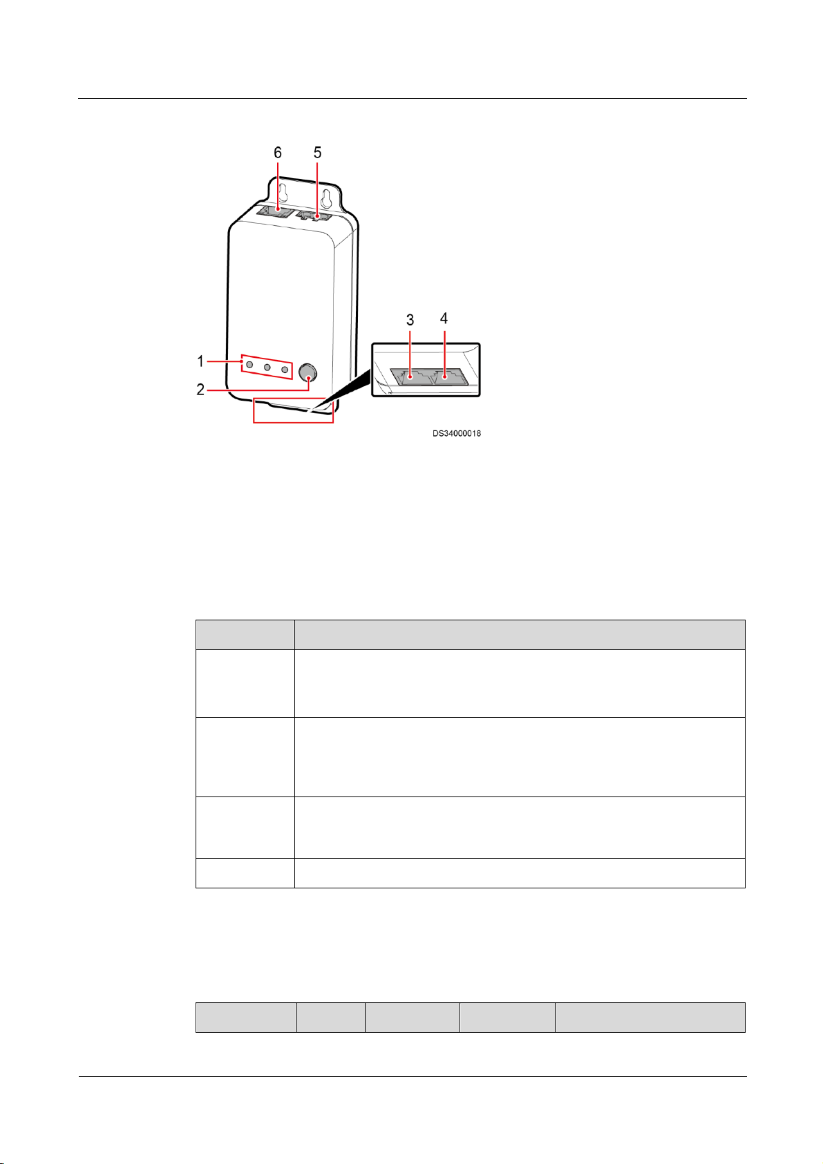
ECC800 Data Center Controller
User Manual
3 Device Description
Issue 02 (2019-02-28)
Copyright © Huawei Technologies Co., Ltd.
58
Figure 3-30 ETH converter
(1) Status indicator
(2) BLINK button
(3) COM1 communications port
(4) COM2 communications port
(5) 48 V power port
(6) PoE port
Item
Specifications
Power input
DC input: Terminal, with input voltage of 36–60 V DC
PoE power supply: One PoE port, 10/100M communication rate,
complying with IEEE802.3at
RS485 or
control area
network
(CAN)
Provides two RS485/CAN ports. The default communications rate for the
RS485 port is 9600 bit/s, and that for the CAN port is 125 kbit/s. Both
ports match the RJ45 terminal shared by RS485 and CAN.
BLINK
button
If you press the BLINK button, the RUN indicator blinks intermittently at
super short intervals (blinking at super short intervals for 0.5s and then off
for 0.5s) for 10 seconds.
E-label
Supported
Indicator
Color
Name
Status
Description
Specifications
Table 3-52 ETH converter technical specifications
Indicators
Table 3-53 ETH converter indicators
Page 68

ECC800 Data Center Controller
User Manual
3 Device Description
Issue 02 (2019-02-28)
Copyright © Huawei Technologies Co., Ltd.
59
Indicator
Color
Name
Status
Description
PWR
Green
Power input
status
indicator
Steady on
The power input is normal.
Off
There is no power input.
RUN
Green
Operating
status
indicator
Off
The power supply is
abnormal.
Blinking at
long intervals
The ETH converter
successfully registers with the
ECC800 and the software
runs properly (the indicator
blinks at 0.5 Hz, on for 1s
and then off for 1s).
Blinking at
short
intervals
The communication fails or
the ETH converter fails to
register with the ECC800 (the
indicator blinks at 4 Hz, on
for 0.125s and then off for
0.125s).
Blinking
The indicator blinks at super
short intervals for 0.5s
(blinking at 10 Hz, on for
0.05s and then off for 0.05s)
and then turns off for 0.5s.
The cycle lasts for 10s.
ALM
Red
Alarm
indicator
Steady on
A system failure alarm is
generated.
Off
No system alarm is
generated.
3.3.16 Pad
The pad allows the wireless access from the data center management system. You can monitor
the equipment in the data center and environmental parameters in real time over the APP.
Figure 3-31 shows a pad.
Page 69

ECC800 Data Center Controller
User Manual
3 Device Description
Issue 02 (2019-02-28)
Copyright © Huawei Technologies Co., Ltd.
60
Figure 3-31 Pad
Item
Specifications
Dimensions (L x W x
H)
248.5 mm x 150 mm x 8.3 mm
Weight
About 433 g
Item
Specifications
Touchscreen
10.1-inch, 1280x800 IPS full view, IPS screen, and capacitive
five-point touch
Chip processor
MSM8916, quad-core A53, 1.2 GHz integrated chip
WLAN
802.11a/b/g/[email protected]&5GHz
Store Machine: 16 GB
Memory: 2 GB LPDDR3
Extension card: microSD, a maximum of 64 GB supported
Button/Port
Power switch and volume button
3.5 mm stereo headphones port
Micro SD card port
Micro-USB port that supports charging and synchronization
with PC data
The pad used in the micro-module is a capacitive touchscreen that supports multi-touch
technology. Table 3-54 lists the pad structural specifications.
Table 3-54 Pad structural specifications
Table 3-55 lists pad technical specifications.
Table 3-55 Pad technical specifications
Page 70
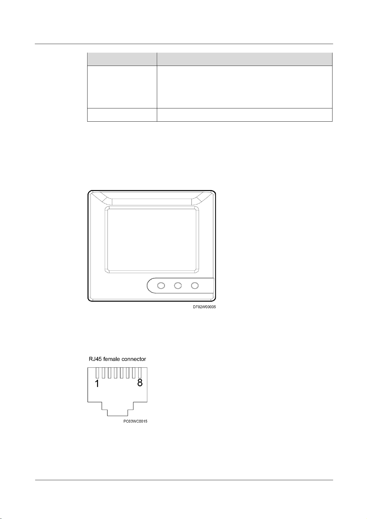
ECC800 Data Center Controller
User Manual
3 Device Description
Issue 02 (2019-02-28)
Copyright © Huawei Technologies Co., Ltd.
61
Item
Specifications
Battery Materials: Li-polymer
Capacity: 4800 mAh
WiFi connection/Web page browse time: about 6.5 hours
Power adapter charge time: about 6 hours
Operating system
Android 4.4 (KitKat)+EMUI 3.0
3.3.17 T/H Sensor
3.3.17.1 T/H sensor (BOM number:33010346)
Figure 3-32 Appearance
The T/H sensor uses an RJ45 connector.
Figure 3-33 Pins of an RJ45 connector
Page 71
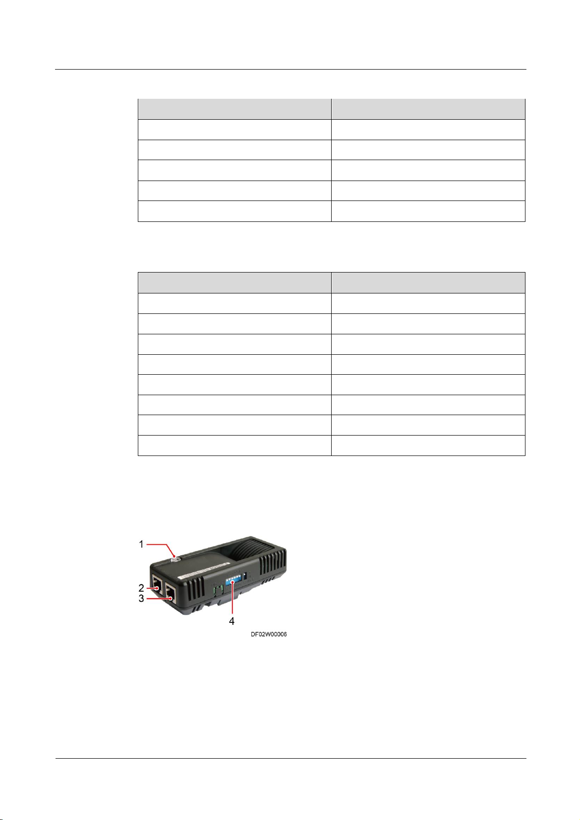
ECC800 Data Center Controller
User Manual
3 Device Description
Issue 02 (2019-02-28)
Copyright © Huawei Technologies Co., Ltd.
62
Table 3-56 Pin description of an RJ45 connector
Pin
Description
Pin 1
A
Pin 2
B
Pin 3
V+
Pin 4/5/6/7
Reserved
Pin8
V-
Item
Specifications
Temperature measuring range
-20°C to 70°C
Temperature accuracy
≤ ±0.3°C (25°C)
Humidity measuring range
0%–100% RH
Humidity accuracy
≤ ±5% RH (25°C, 30%–80% RH)
Operating temperature
-20°C to 70°C
Operating voltage
9–16 V DC
Storage temperature
-40°C to 80°C (non-condensing)
Output
RS485
(1) Status indicator
(2) RS485_IN
(3) RS485_OUT
(4) Address DIP switch
Table 3-57 T/H sensor specifications
3.3.17.2 T/H Sensor (BOM number:02310NBS)
Figure 3-34 Appearance
The RS485 communications ports of the T/H sensor use RJ11 (6P6C) connectors.
Page 72
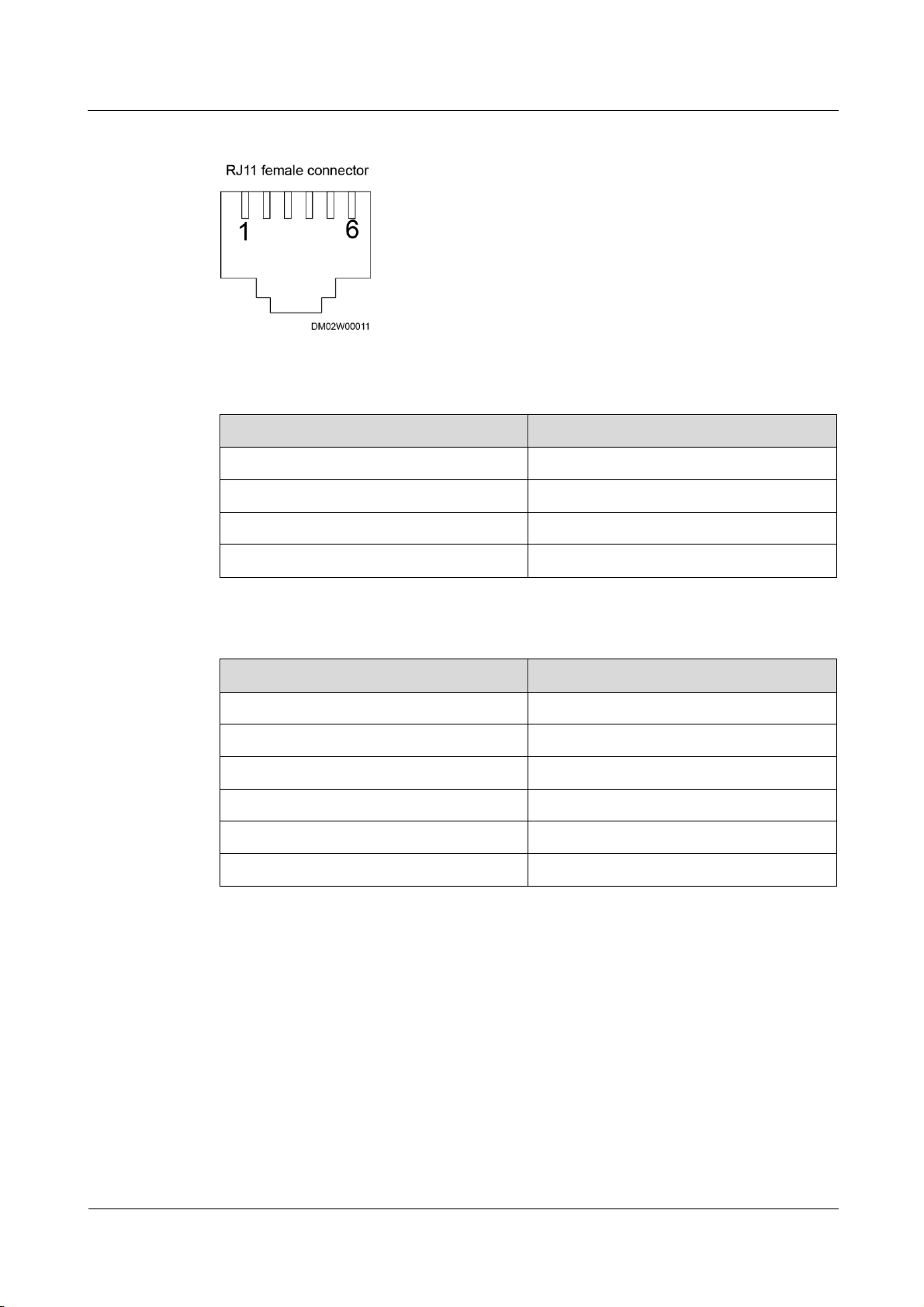
ECC800 Data Center Controller
User Manual
3 Device Description
Issue 02 (2019-02-28)
Copyright © Huawei Technologies Co., Ltd.
63
Figure 3-35 Pins of an RJ11 connector
Pin
Description
Pin 1 or Pin 2
GND
Pin 3
RS485-
Pin 4
RS485+
Pin 5 or Pin 6
12V
Item
Specifications
Temperature measuring range
–20°C to +70°C
Temperature accuracy
±1°C
Operating temperature
–10°C to +55°C
Operating voltage
9–16 V DC
Storage temperature
–40°C to +70°C
Output
RS485
Table 3-58 Pin description of an RJ11 connector
Table 3-59 Temperature and humidity sensor specifications
Page 73
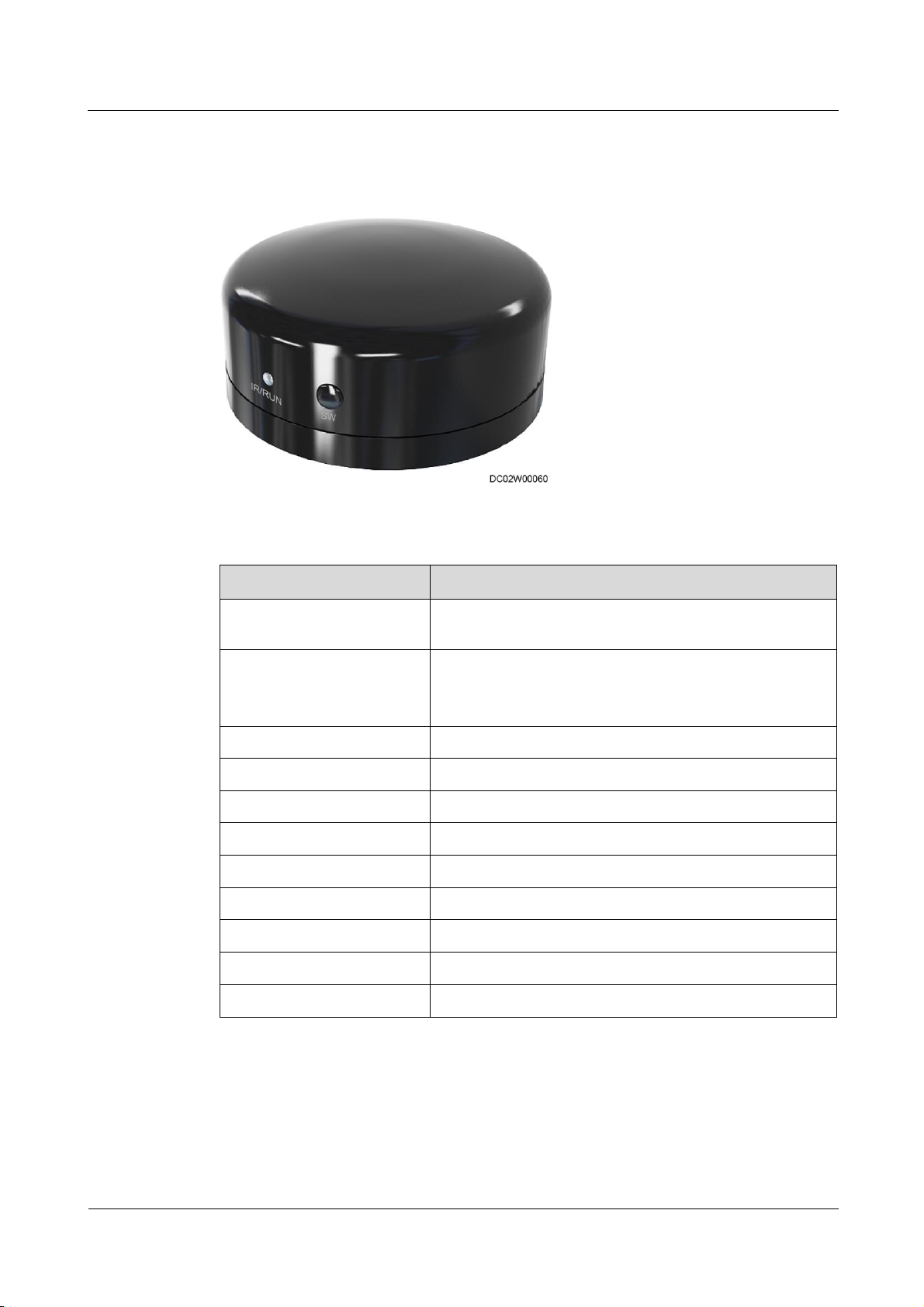
ECC800 Data Center Controller
User Manual
3 Device Description
Issue 02 (2019-02-28)
Copyright © Huawei Technologies Co., Ltd.
64
3.3.18 Infrared Remote Control Module
Item
Specification
Number of supported remote
control commands
≤ 4
Communication
Interworks with the monitoring system over Modbus-RTU
to implement remote control.
The baud rate can be 9600 bit/s.
Infrared emission distance
≤ 10 m
Power supply
9–16 V DC
Power
≤ 350 mA
Operating temperature
–10°C to +50°C
Operating humidity
5%–95% RH
Protection level
IP20
Indicator
Communication indicator and Run indicator
Color
Black
Address setting
Supports Modbus address setting
Figure 3-36 Appearance
Table 3-60 Technical specifications
3.3.19 SMS Module
Before using the SMS module, ensure that GSM/WCDMA signals must be available in the
equipment room, and a SIM card needs to be prepared.
Page 74
ECC800 Data Center Controller
User Manual
3 Device Description
Issue 02 (2019-02-28)
Copyright © Huawei Technologies Co., Ltd.
65
Table 3-61 Technical specifications
Item
Specification
Power voltage
4.75–5.25 V (recommended value: 5 V)
Operating temperature
-20°C to +55°C
Storage temperature
-40°C to +70°C
Chip
Hi6758
Application interface
Standard SIM card (compatible with 3
V/1.8 V)
USB 2.0 port
Short message service
Short text messages are supported.
Weight
22 g
Certification
CE, FCC, and GCF
The USB port supports SMS module. Its functions are as follows:
Implements alarm notification by SMS.
− Sets Mobile number and Alarm Severity, and receives the alarm notification by
SMS after an alarm is generated or eliminated.
− Sends an active alarm after the ECC800 powers off and restarts.
The SMS function of the 3G module in the ECC800 cannot coexist with the external SMS
module connected to the USB port.
3.3.20 Intelligent Battery Monitoring System
The intelligent battery monitoring system consists of the CIM (CIM01C2) and BIM
(BIM01C3).
The communication interface module (CIM) is an intelligent battery management module that
collects wireless communication data from the downstream battery interface module (BIM)
groups, collects and analyzes the operating data of battery strings, calculates state of charge
(SOC) and state of health (SOH) of batteries and battery strings and estimates the battery
health status accordingly, supports battery tripping management, and uploads data to the
management unit through COM or PoE ports.
The BIM is a battery monitoring module that monitors the voltages, internal resistances, and
pole temperatures of batteries.
One CIM can manage BIMs of a maximum of four battery strings.
The BIM01C3 supports Shoto and Enersys batteries.
Page 75
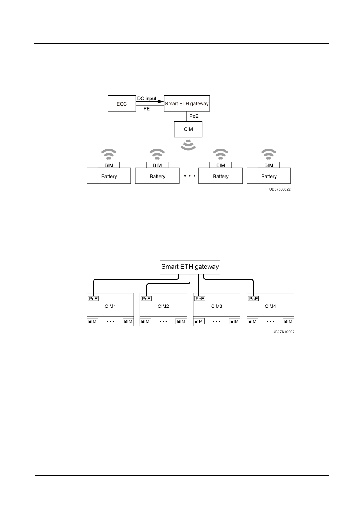
ECC800 Data Center Controller
User Manual
3 Device Description
Issue 02 (2019-02-28)
Copyright © Huawei Technologies Co., Ltd.
66
In the scenario with battery cabinets, the CIM is installed inside a smart module battery
cabinet and the CIM communications cable connects to a smart ETH gateway. Figure 3-37
shows the CIM and BIM networking in the scenario with battery cabinets.
Figure 3-37 CIM and BIM networking (in the scenario with battery cabinets)
When a battery system needs to be managed by multiple CIMs, the CIMs can be connected to
northbound devices using straight-through cables (the ECC supports four CIMs in parallel
through the smart ETH gateway) without cascading. Figure 3-38 shows the system
networking.
3.3.20.1 CIM
Features
Figure 3-38 CIM communications cable connecting to a smart ETH gateway
CIM is a battery information collection module. It collects battery status data from the
downstream BIM groups through wireless communication, and sends the data to the ECC,
UPS, and the third-party network management system (NMS) through COM or PoE ports.
Collects battery data detected by the BIM through wireless communication.
Each CIM can manage a maximum of four battery strings or 300 batteries.
An external Hall effect sensor is connected to monitor the current of each battery string.
Calculates the SOC and SOH of batteries and battery strings.
Accurately identifies weak batteries in a battery string.
Page 76
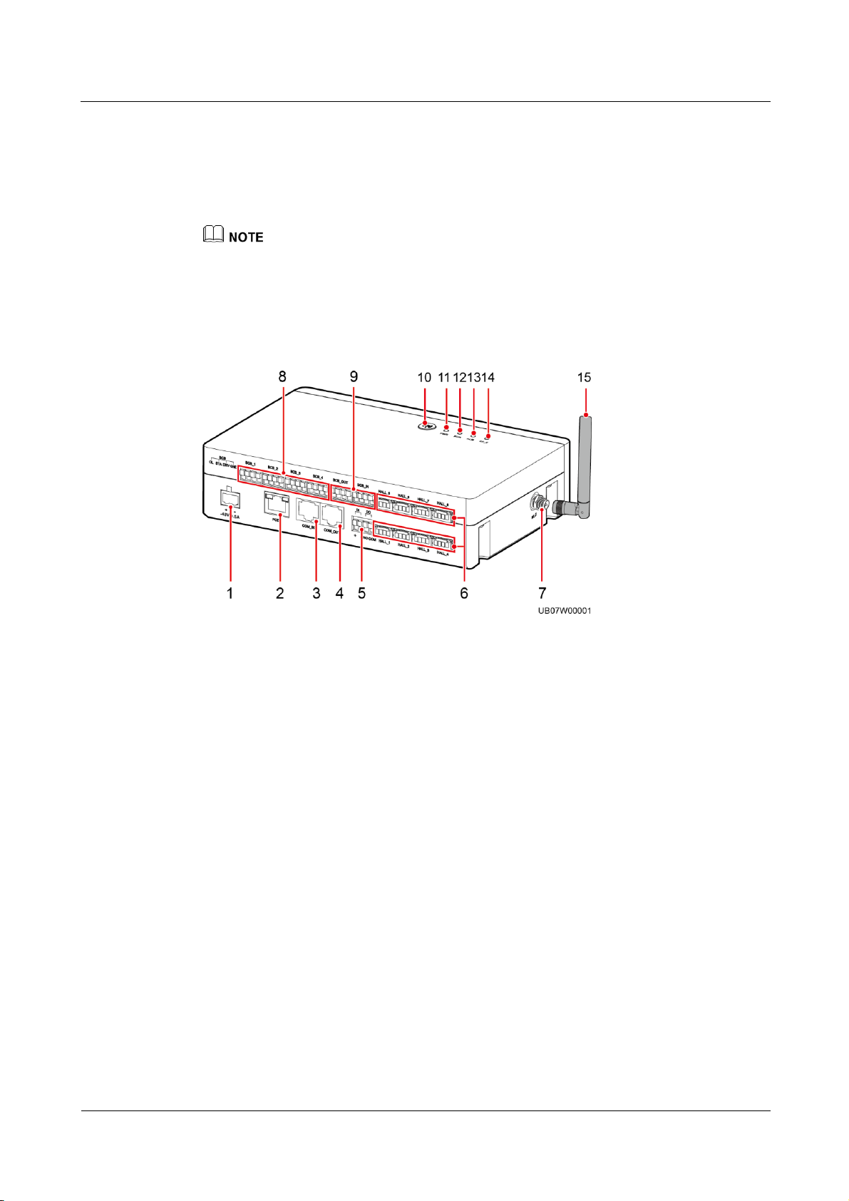
ECC800 Data Center Controller
User Manual
3 Device Description
Issue 02 (2019-02-28)
Copyright © Huawei Technologies Co., Ltd.
67
Appearance
(1) –48 V 0.5 A port (power
input)
(2) PoE port
(3) COM_IN port (RS485
communication input)
(4) COM_OUT port (RS485
communication output)
(5) DI and DO ports
(6) HALL_1–HALL_8 current
monitoring ports
(7) RF_Z antenna port
(8) BCB_1–BCB_4
ports
(9) BCB_OUT and BCB_IN
ports
(10) Networking switch
(11) PWR indicator
(12) RUN indicator
(13) ALM indicator
(14) RF_Z indicator
(15) Delivered antenna
Identifies loose battery terminals and battery terminal overtemperature, and controls
battery switch tripping.
Supports WebUI display, northbound communication over FE and RS485, and a
third-party NMS.
Supports CIM and BIM online upgrade on the monitoring system.
If the upgrade package is transmitted to the CIM, and the upgrade is complete. The BIM upgrade is
finished through the CIM backend.
Figure 3-39 CIM front view
Page 77
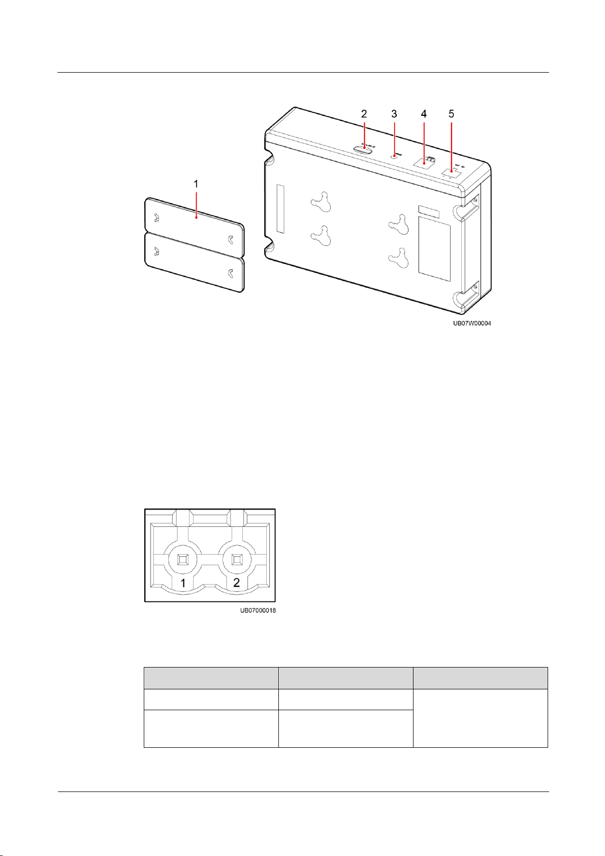
ECC800 Data Center Controller
User Manual
3 Device Description
Issue 02 (2019-02-28)
Copyright © Huawei Technologies Co., Ltd.
68
Figure 3-40 CIM bottom view
(1) Fastener
(2) Micro SD card slot
(3) Default button (IP
reset)
(4) ADDR dual in-line package (DIP) switch (RS485
communications address)
(5) 12V 2A port (power
input)
Pin
Definition
Description
1
–
In this scenario, an external
power module is adopted to
supply 12 V DC operating
voltage.
2
+
Power Port
Figure 3-41 Power port pins
Table 3-62 12 V, 2 A port pin definitions
Page 78
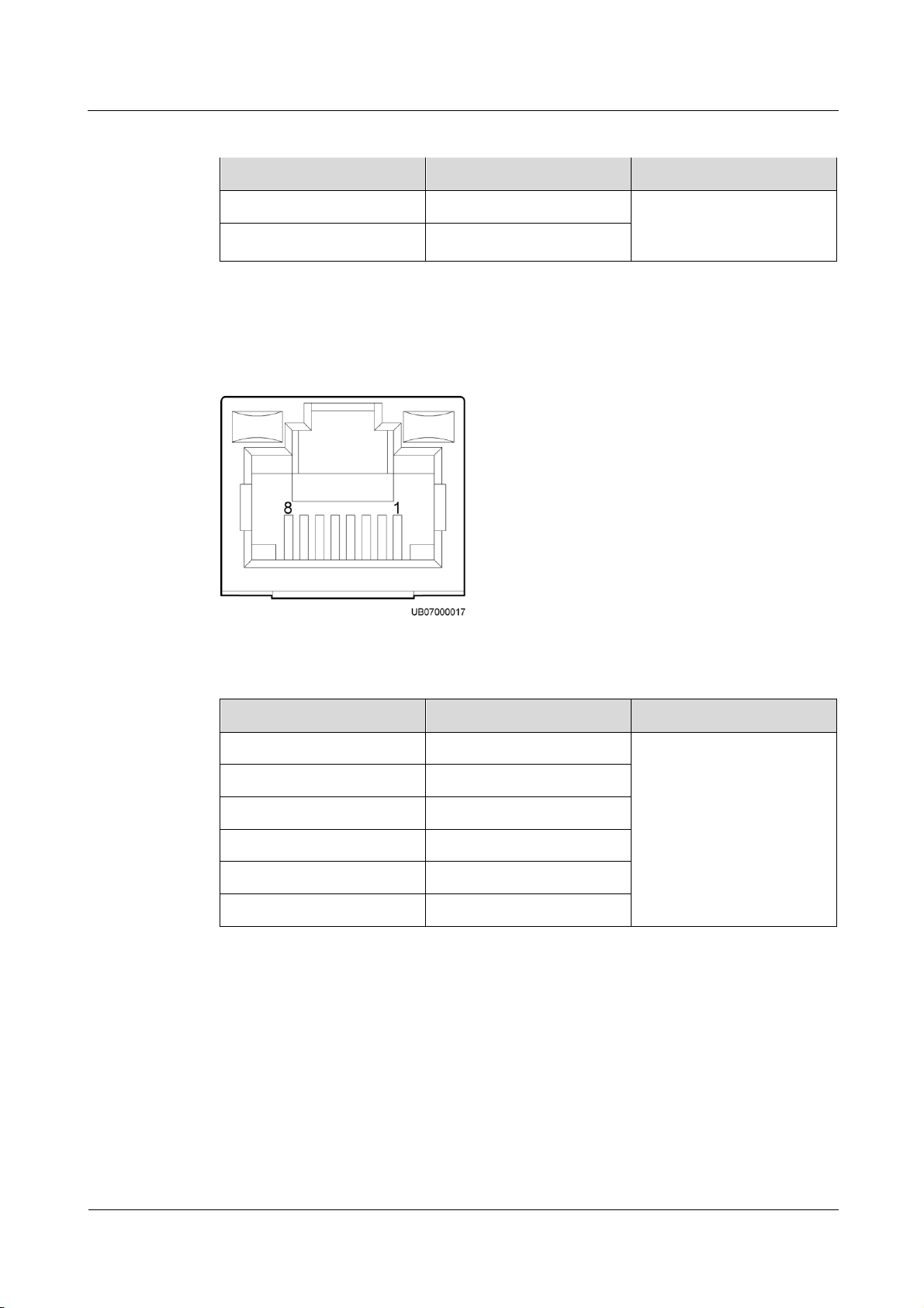
ECC800 Data Center Controller
User Manual
3 Device Description
Issue 02 (2019-02-28)
Copyright © Huawei Technologies Co., Ltd.
69
Pin
Definition
Description
1
+
The system provides 48 V
DC operating voltage in this
scenario.
2
–
PoE Port
Pin
Definition
Description
1
TX+
Supports power supply
through the PoE port. The
terminal is an RJ45 terminal
with an indicator.
2
TX–
3
RX+
4, 5
P45_P1
6
RX–
7, 8
P78_P1
Table 3-63 –48 V, 0.5 A port pin definitions
Figure 3-42 PoE port pins
Table 3-64 PoE port pin definitions
Page 79
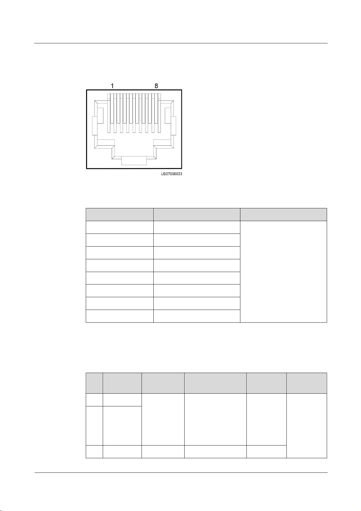
ECC800 Data Center Controller
User Manual
3 Device Description
Issue 02 (2019-02-28)
Copyright © Huawei Technologies Co., Ltd.
70
COM Port
Pin
Signal
Description
1
RS485+
Two cascaded RS485
communication ports
2
RS485–
3
NC 4 RS485+
5
RS485–
6
GND
7
NC 8 NC
Pin
Definition
Signal
Description
Status Description
Initial
Status
Remarks
1
+
Dry contact
input signal
Open: The dry
contact input is
open.
Closed: The dry
contact input is
closed.
Open
Dry contact
input and
output signal
2
–
3
NO
Dry contract
Open: The dry
Open
Figure 3-43 COM port pins
Table 3-65 COM port pin definitions
DI and DO Ports
Table 3-66 DI and DO port pin definitions
Page 80
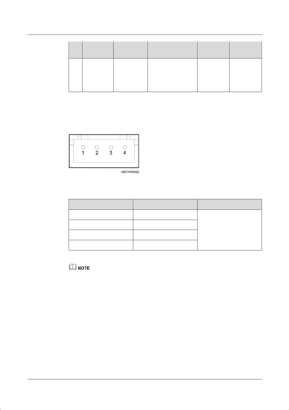
ECC800 Data Center Controller
User Manual
3 Device Description
Issue 02 (2019-02-28)
Copyright © Huawei Technologies Co., Ltd.
71
Pin
Definition
Signal
Description
Status Description
Initial
Status
Remarks
4
COM
output signal
contact output is
open.
Closed: The dry
contact output is
closed.
Pin
Definition
Description
1
+12 V
Detect the charge and
discharge currents of four
battery strings or eight
battery routes.
2
–12 V
3
AI
4
GND
HALL Current Monitoring Port
Figure 3-44 HALL Current monitoring port pins
Table 3-67 HALL Current monitoring port pin definitions
If the battery string is configured with the neutral wire, measure the currents of the positive and
negative battery string cables. If the battery string is not configured with the neutral wire, measure
the current of either the positive or negative battery string cable. The following uses the scenario
where the battery string is configured with the neutral wire as an example.
When a CIM manages multiple battery strings, first connect the Hall effect sensors on the positive
and negative cables of battery string 1 respectively to the corresponding ports on the CIM. Then
connect the Hall effect sensors on battery string 2 to the CIM in the same way, and so on.
If the positive or negative battery string cable is too thick to be routed through the Hall effect sensor,
or the measurement range of the Hall effect sensor is not enough, use multiple Hall effect sensors to
monitor the current of one battery string. The CIM supports the sum of the monitoring results of
multiple Hall effect sensors, which is set through Multi-Hall cur. setting.
The value of Multi-Hall cur. setting equals the number of positive or negative Hall effect sensors in
a single battery string and should be greater than or equal to 1.
Page 81
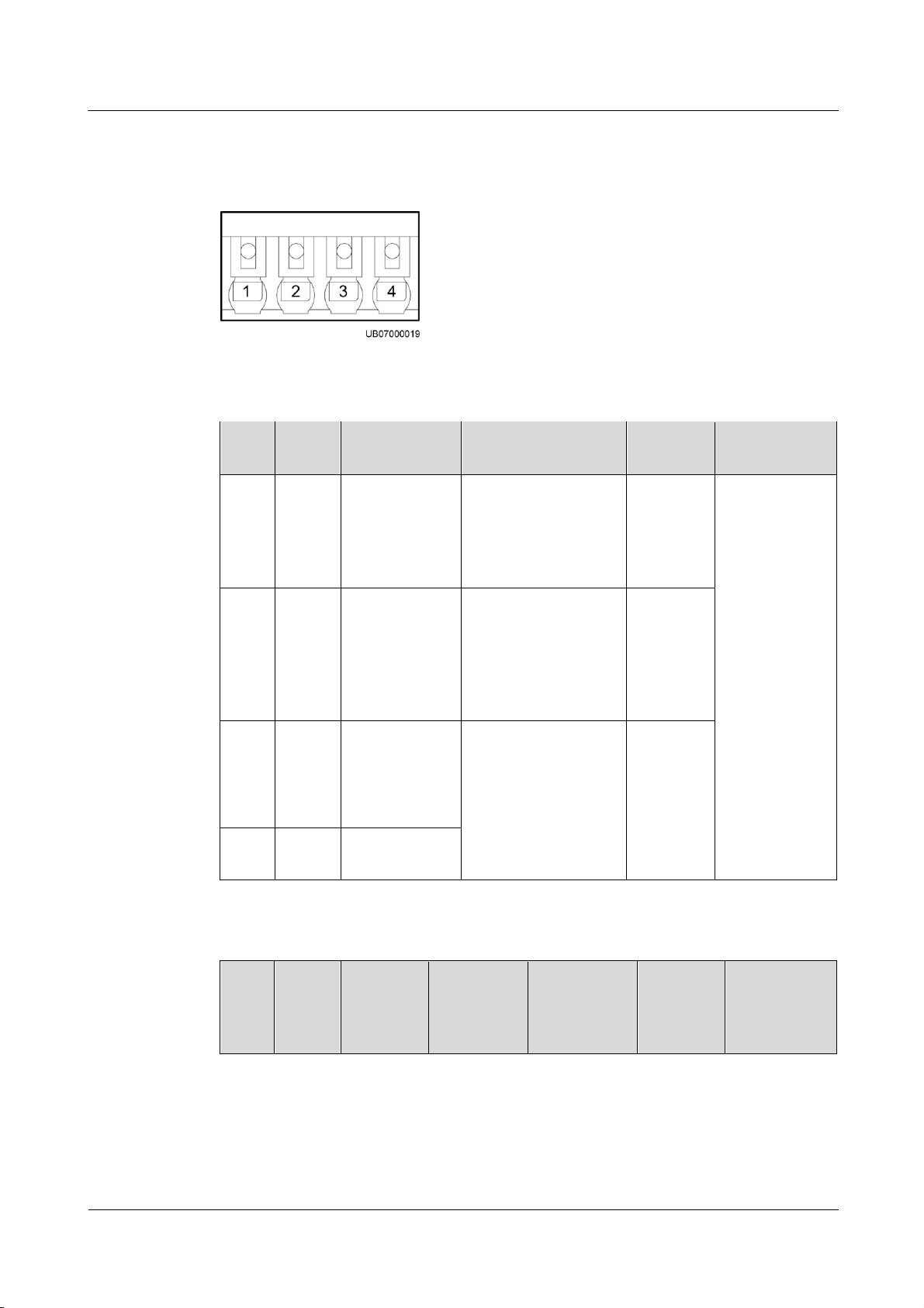
ECC800 Data Center Controller
User Manual
3 Device Description
Issue 02 (2019-02-28)
Copyright © Huawei Technologies Co., Ltd.
72
BCB Port
Pin
Defini
tion
Signal
Description
Status Description
Initial
Status
Remarks
1
OL
Monitors
whether the
BCB box is
connected
Grounded: BCB
connected.
Disconnected:
BCB not
connected.
Disconnec
ted
The four BCBs
can separately
manage
tripping of four
battery routes.
2
STA
Monitors the
battery circuit
breaker
Grounded: The
battery circuit
breaker is ON.
Disconnected: The
battery circuit
breaker is OFF.
Disconnec
ted
3
DRV
Controls
battery circuit
breaker trip and
outputs 12 V
driving signals
0 V: There is no
driving signal for
BCB tripping.
12 V: There is a
driving signal for
BCB tripping.
0 V
4
GND
Secondary side
ground
Pin
Defini
tion
BCB_IN
Signal
Descripti
on
BCB_OUT
Signal
Descriptio
n
Status
Description
Initial
Status
Description
Figure 3-45 BCB port pins
Table 3-68 BCB_1–BCB_4 port pin definitions
Table 3-69 BCB_IN and BCB_OUT cascading port pin definitions
Page 82

ECC800 Data Center Controller
User Manual
3 Device Description
Issue 02 (2019-02-28)
Copyright © Huawei Technologies Co., Ltd.
73
Pin
Defini
tion
BCB_IN
Signal
Descripti
on
BCB_OUT
Signal
Descriptio
n
Status
Description
Initial
Status
Description
1
OL
Specifies
whether
the BCB
connects
to the
signal
output
port.
Specifies
whether the
cascaded
BCBs
connect to
the signal
input port.
Grounded:
BCB
connected.
Disconnec
ted: BCB
not
connected.
Disconnec
ted
Receives
BCB
commands
sent by the
UPS and
supports BCB
port cascading
management.
2
STA
Signal
output
port for
the battery
circuit
breaker
status
Monitors
whether the
cascaded
BCBs are
connected
to the input.
Grounded:
The
battery
circuit
breaker is
ON.
Disconnec
ted: The
battery
circuit
breaker is
OFF.
Disconnec
ted
3
DRV
Controls battery circuit
breaker trip and receives
12 V driving signals
0 V: There
is no
driving
signal for
BCB
tripping.
12 V:
There is a
driving
signal for
BCB
tripping.
0 V
4
GND
Secondary side ground
No.
Definition
Description
1
ADDR_1
RS485 communications
address setting
2
ADDR_2
3
ADDR_3
4
ADDR_4
DIP Switch
Table 3-70 DIP switch description
Page 83

ECC800 Data Center Controller
User Manual
3 Device Description
Issue 02 (2019-02-28)
Copyright © Huawei Technologies Co., Ltd.
74
Indicators
Indicator
Color
Meaning
Status
Description
Measure
RF_Z
Green
Wireless
communication
status
Steady
on
No network
parameters exist.
(A network is to
be created.)
Requires no
handling.
Blinking
at super
short
intervals
A network is
being created
(new nodes
allowed).
Blinking
at long
intervals
Data is being
transmitted (new
nodes not
allowed).
RUN
Green
Northbound
communication
status
Blinking
at long
intervals
The
communication
is normal.
Requires no
handling.
Blinking
intermitt
ently at
super
short
intervals
Blinking, lasting
for 10s.
Requires no
handling.
Table 3-71 Indicator description
Page 84

ECC800 Data Center Controller
User Manual
3 Device Description
Issue 02 (2019-02-28)
Copyright © Huawei Technologies Co., Ltd.
75
Indicator
Color
Meaning
Status
Description
Measure
Blinking
at short
intervals
Communication
fails. (No
legitimate
northbound data
has been
received for 3
minutes.)
1. Check
whether the
communicatio
n cable is
loose.
If yes,
reconnect
the
communic
ation cable.
If no, go to
the next
step.
2. Check
whether the
device is
malfunctionin
g.
If yes,
replace the
device.
If no,
contact
Huawei
technical
support.
ALM
Red
Alarm indicator
Steady
on
The actual
number of
online devices is
less than the
value of BIM
number.
Check the value
of BIM number,
the BIM cable
connection, and
the BIM
indicators.
Off
The actual
number of
online devices
equals the value
of BIM number.
Requires no
handling.
PWR
Green
Power indicator
Steady
on
Board power
indicator.
Requires no
handling.
If an indicator blinks at long intervals, it is blinking at 0.5 Hz, that is, on for 1s and then off for 1s.
If an indicator blinks at short intervals, it is blinking at 4 Hz, that is, on for 0.125s and then off for
0.125s.
If an indicator blinks at super short intervals, it is blinking at 10 Hz, that is, on for 0.05s and then off
for 0.05s.
Page 85

ECC800 Data Center Controller
User Manual
3 Device Description
Issue 02 (2019-02-28)
Copyright © Huawei Technologies Co., Ltd.
76
Name
Definition
Function
Button pressing
Press the button for
less than 1s.
CIM blinking function
Button pressing
Press and hold the
button for more than
1s but less than 5s.
Creates a network if no network has
been created. Switches between network
organization and data transmission if a
network has been created.
Button holding down
Press and hold the
button for more than
10s but less than 20s.
Clears the current network (including
the network parameters of all the online
BIMs).
Name
Definition
Function
Default button
Hold down the button
for more than 10
seconds.
Reset to the default IP address
(192.168.0.10)
Networking Switch
Table 3-72 Networking switch description
Blinking intermittently at super short intervals means an indicator blinks at super short intervals for
0.5s and then remains off for 0.5s.
Default Button
3.3.20.2 BIM
Features
Table 3-73 Default button description
The BIM is a battery monitoring module that monitors the voltages, internal resistances, and
pole temperatures of batteries and supports 12 V power.
Monitors the voltages, internal resistances, and pole temperatures of 12 V batteries.
Supports the hibernation function. (When it detects that the battery voltage is low, it will
enter the low-power mode.)
Communicates with the CIM wirelessly.
Page 86
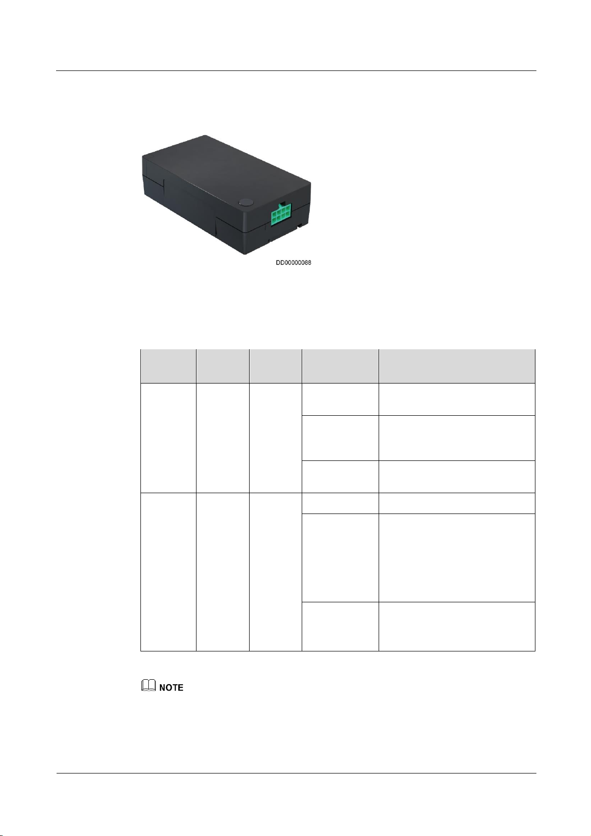
ECC800 Data Center Controller
User Manual
3 Device Description
Issue 02 (2019-02-28)
Copyright © Huawei Technologies Co., Ltd.
77
BIM Appearance
Indicator
Color
Silk
Screen
Status
Description
Running
Green
RUN
Off
Power consumption is low or the
BIM is not powered on.
Blinking at
super short
intervals
The networking has started but not
completed.
Blinking at
long intervals
The networking succeeds.
Alarm
Red
ALM
Off
The BIM is not faulty.
Steady on
The BIM is faulty.
Communication with the CIM
times out.
No network is connected. (The
BIM is waiting to connect to a
network.)
Blinking at
super short
intervals
Network parameters are being
cleared.
The BIM is blinking.
Figure 3-46 BIM
Indicators
Table 3-74 Indicator description
If an indicator blinks at long intervals, it is blinking on for 1s and then off for 1s.
If an indicator blinks at super short intervals, it is blinking at 10 Hz, that is, on for 0.05s and then off
for 0.05s.
Page 87

ECC800 Data Center Controller
User Manual
3 Device Description
Issue 02 (2019-02-28)
Copyright © Huawei Technologies Co., Ltd.
78
Networking Switch
Name
Definition
Function
Button pressing
Press the button for less
than 5 seconds.
Searches for and joins a network if there is no
network. Initializes the network parameters if
there is a network.
Button holding
down
Hold down the button
for more than 5
seconds.
Clears the current network and resets the
wireless module; disconnect the network.
Table 3-75 Networking switch description
Page 88

ECC800 Data Center Controller
User Manual
4 UI Description
Issue 02 (2019-02-28)
Copyright © Huawei Technologies Co., Ltd.
79
4.1 WebUI Introduction
Port
Default IP Address
WAN_1
192.168.1.10
WAN_2
192.168.248.10 (FusionModule800)
192.168.0.10
(FusionModule500/FusionModule1000/FusionModule2
000/FusionModule5000)
LAN_1 and LAN_2
192.168.248.10
4.1.1 Preparations and WebUI Login
Prerequisites
4 UI Description
Procedure
Step 1 Connect a network cable between the PC network port and the WAN_1 port (protected by a
User rights:
The default user with administrator rights is admin. The preset password is Changeme.
The admin user has all WebUI operation rights.
The default user with operation rights is operator. The preset password is Changeme. The
operator user has no rights for parameter setting, control, and maintenance that may
affect system running.
WebUI operating environment requirements:
Operating system: Windows 7 or later
Browser: Internet Explorer 8.0 or later; Firefox 38.0.5 or later; Chrome 46.0.2490.80 or
later
security mechanism) on the ECC800.
Table 4-1 Default IP addresses for the WAN and LAN ports on the ECC800
Page 89

ECC800 Data Center Controller
User Manual
4 UI Description
Issue 02 (2019-02-28)
Copyright © Huawei Technologies Co., Ltd.
80
The WAN_1 port IP address cannot be set to an IP address in any of the following network
segments: 192.168.0.x, 192.168.8.x, 192.168.248.x, and 192.168.245.x.
IP addresses for the WAN_1 and WAN_2 ports should not be set in the same network
segment.
Step 2 Configure the PC IP address and the WAN_1 IP address in the same network segment.
If the port IP address is 192.168.1.10, subnet mask is 255.255.255.0, and default gateway is
192.168.1.1, set the PC IP address to 192.168.1.11, subnet mask to 255.255.255.0, and default
gateway to 192.168.1.1.
Step 3 Set LAN parameters.
If the ECC800 connects to a LAN and a proxy server has been selected, perform Step 3.3 and Step
3.4.
If the ECC800 connects to the Internet, and the PC in a LAN accesses the Internet over a proxy
server, do not perform Step 3.3 or Step 3.4. Otherwise, you will fail to access the ECC800.
1. Open the Internet Explorer and choose Tools > Internet Options.
2. Click the Advanced tab and select Use TLS1.1 and Use TLS1.2.
3. (Optional) Click the Connections tab and select LAN settings.
4. (Optional) Under Proxy server, clear Use a proxy server for your LAN.
5. Click OK.
Page 90
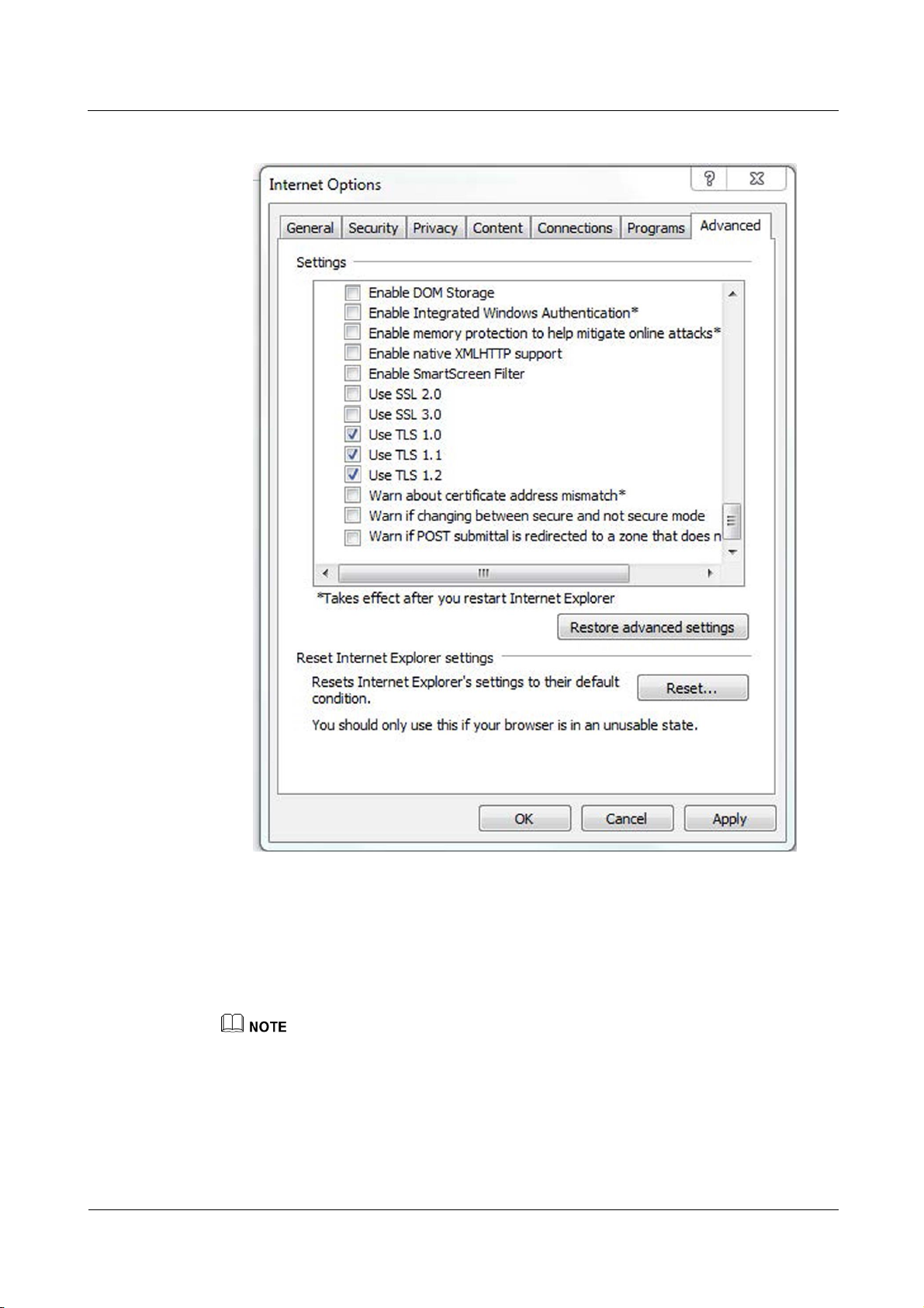
ECC800 Data Center Controller
User Manual
4 UI Description
Issue 02 (2019-02-28)
Copyright © Huawei Technologies Co., Ltd.
81
Figure 4-1 Setting internet options
Step 4 Set Internet Explorer parameters.
1. When you use Internet Explorer for access, set Internet Explorer to ensure the normal
display of and operations on the WebUI. Choose Tools > Compatibility View.
2. Add the ECC800 IP address to the list of trusted sites and enable automatic file
downloading. Then set the security level of the trusted site to the lowest.
When switching between different versions of the ECC800 on your PC, you are advised to clear the
historical Internet Explorer cache. Failing to do so may cause some information missed or exception
after login. The following provides the details:
Page 91
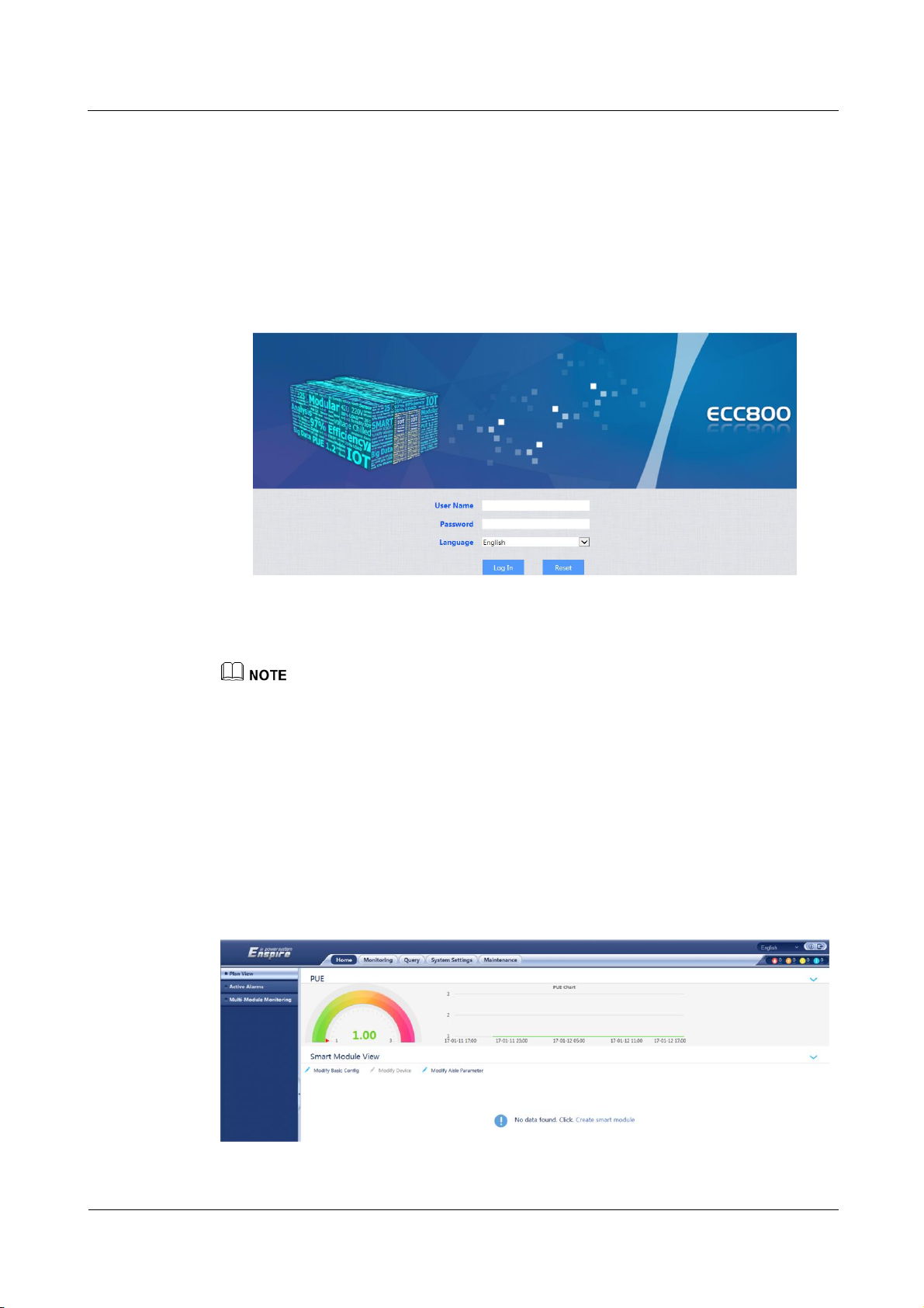
ECC800 Data Center Controller
User Manual
4 UI Description
Issue 02 (2019-02-28)
Copyright © Huawei Technologies Co., Ltd.
82
1.
Open Internet Explorer and choose Tools > Internet Options > General.
2.
Select Delete browsing history on exit and click Delete.
3.
In the Delete Browsing History dialog box, select all options except Password, and click Delete.
Step 5 Log in to the ECC800 WebUI.
1. Enter https://monitoring IP address (such as https://192.168.1.10) in the address box of
the browser, and then press Enter to enter the WebUI login page.
Figure 4-2 WebUI login page
4.1.2 WebUI
2. On the login page, enter the preset user name admin and preset password Changeme,
set the language, and click Log In.
Change the password after your first login.
An account is logged out due to timeout if no operation is performed within 10 minutes after system
login.
It is recommended that a maximum of three users log in to the ECC WebUI at the same time.
----End
For data transmission security, the ECC800 supports WebUI access through TLS.
Figure 4-3 Home page
Page 92
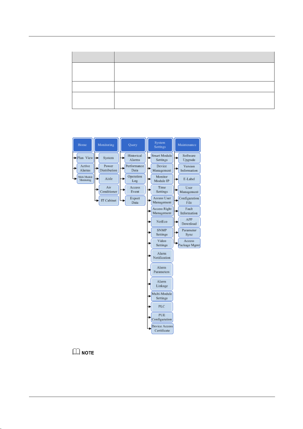
ECC800 Data Center Controller
User Manual
4 UI Description
Issue 02 (2019-02-28)
Copyright © Huawei Technologies Co., Ltd.
83
Table 4-2 Functions provided by the home page
Tab
Functions
Plan View
View and manage the layout view of devices.
View the system PUE in a dashboard and the system trend curve.
Active Alarms
Query active alarms.
Multi-Module
Monitoring
View the status of each cascaded ECC800.
Figure 4-4 WebUI menu hierarchy
The actual menu hierarchy prevails.
Multi-Module Monitoring is displayed on the Home page only after Multi-Module Settings are
configured.
Page 93

ECC800 Data Center Controller
User Manual
4 UI Description
Issue 02 (2019-02-28)
Copyright © Huawei Technologies Co., Ltd.
84
WebUI Common Functions
Menu
Functions
Monitoring
Monitor the device running information in real time, set device running
parameters, and control the device running. For example, set smart
cooling product parameters, delete devices failing in communication,
and set AI/DI device parameters.
Query Query historical alarms, performance data, and operation logs.
Export historical data and device data.
Check access control events.
System Settings
Set alarm parameters.
Set the time zone, time, and date.
Set the monitoring module IP address, SNMP, and NetEco network
parameters.
Set the system type and site ID.
Install network security certificates and device access certificates.
Set PLC linkage rules.
Set the access users and permissions.
Set alarm notification by email and SMS.
Set PUE parameters.
Configure multi-module settings to cascade up to three ECC800s.
Maintenance
Upgrade the software of the ECC800 and southbound devices and
download the app.
Query the version and e-labels.
Query and export fault information.
Implement user management, for example, adding and deleting a
user.
Import and export configuration files to configure devices quickly,
and restore factory settings.
Synchronize device parameters to quickly import data of southbound
devices (such as the multi-functional sensor and skylight actuator).
Table 4-3 WebUI common functions
4.2 APP Introduction
4.2.1 Connecting to a WiFi Network
Prerequisites
You can connect a WiFi module or a WiFi converter to a WiFi network.
Page 94
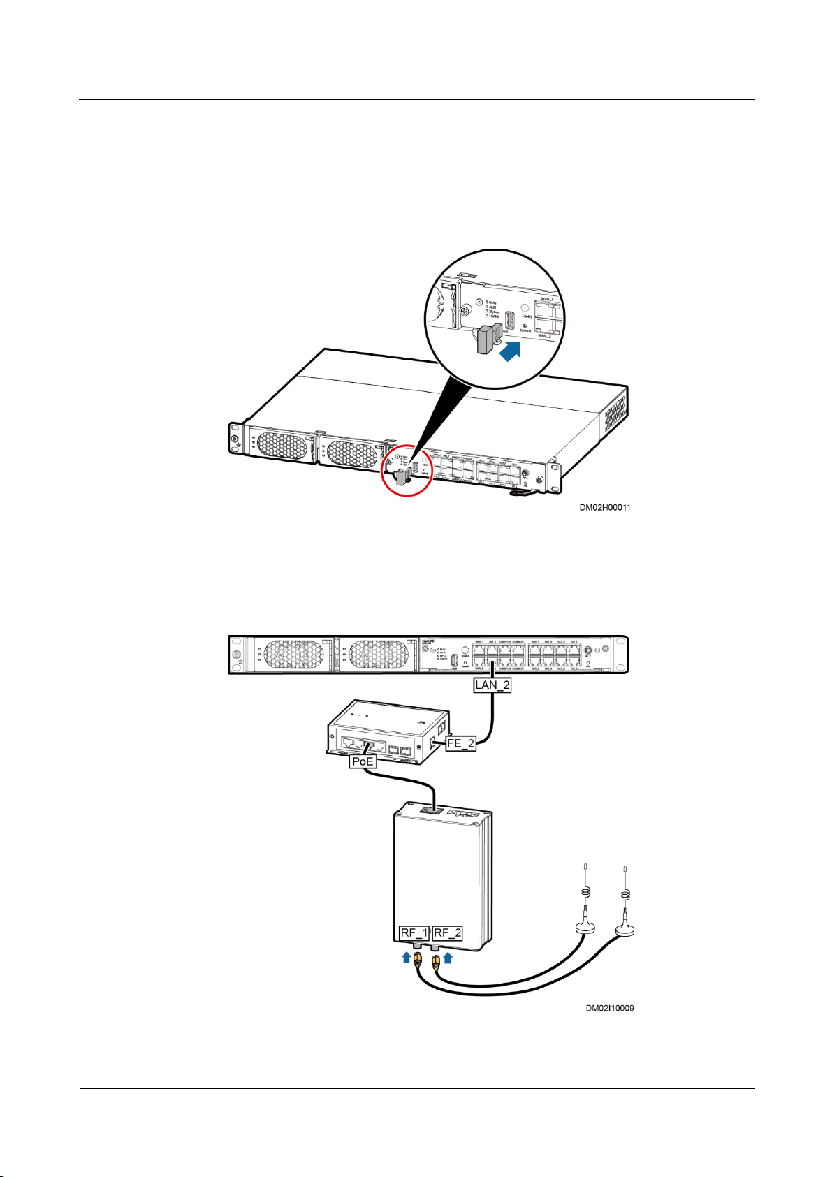
ECC800 Data Center Controller
User Manual
4 UI Description
Issue 02 (2019-02-28)
Copyright © Huawei Technologies Co., Ltd.
85
Procedure
Step 1 Connecting to a WiFi network.
Method 1: Insert a WiFi module into the USB port on the ECC800.
Figure 4-5 Installing a WiFi module
Method 2: Connect cables between the WiFi converter and a smart ETH gateway as well
as between the smart ETH gateway and the ECC800.
Figure 4-6 Installing a WiFi converter
Page 95
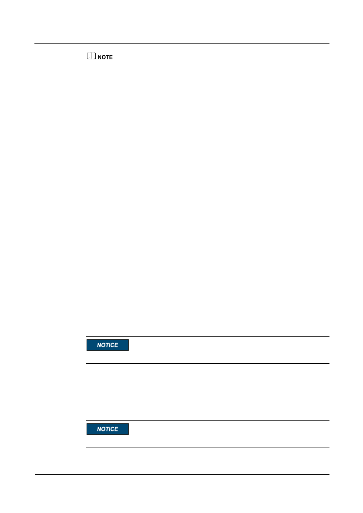
ECC800 Data Center Controller
User Manual
4 UI Description
Issue 02 (2019-02-28)
Copyright © Huawei Technologies Co., Ltd.
86
The WiFi antenna should be installed on the planned position by using the magnet.
----End
4.2.2 Preparations and App Login
Prerequisites
App operating environment requirements:
The mobile device must run Android 4.0 or later and is not root operation system (the
operating system is not flashed).
The mobile device must have sufficient space for installing the new app. The size of the
app installation package is 7 MB, and the size of files after app installation is about 11
MB.
The mobile device has sufficient battery reserve.
You have obtained the IP address of the ECC800 as well as the user name and password
used for WebUI login.
A PC with an IP address in the same network segment as that of the ECC800 is prepared,
and the PC has connected to port WAN_1 on the ECC800.
Procedure
Step 1 Download and obtain the app installation package using any of the following three methods:
Log in to HUAWEI App Store (http://a.vmall.com/) or Google Play, search for
FusionModule, and tap Download.
− Outside China: Tap the Google Play app and search for FusionModule.
In China:
i. Set the pad language to Chinese.
ii. Open the browser on the pad, enter www.baidu.com in the address box, search
for HUAWEI App Store, select Ordinary Download, and tap Save.
Do not use the Google Play to download the HUAWEI App Store.
iii. Install the HUAWEI App Store. If the downloaded file exists in the drop-down
list box, tap the file to install the HUAWEI App Store. If the downloaded file
does not exist in the drop-down list box, choose File > Local on the desktop,
find the Download folder, and click the HUAWEI App Store installation
package.
After you open the HUAWEI App Store, select NOT NOW if "New Version" is displayed.
Page 96

ECC800 Data Center Controller
User Manual
4 UI Description
Issue 02 (2019-02-28)
Copyright © Huawei Technologies Co., Ltd.
87
Log in to the ECC800 WebUI using a PC. Choose Maintenance > APP Download,
click Download APP, and save the app installation package to the PC or a path on the
mobile storage device. Then, copy the app installation package to a mobile phone or pad.
When the WiFi is enabled, enter https://192.168.245.10 in the address bar of the Firefox
browser (version 41.0 or later) on a mobile phone or pad, and press Enter to access the
ECC800 WebUI. Choose Maintenance > APP Download and click Download APP to
save the app package to the mobile phone or pad.
Step 2 Install the app.
By default, the Android operating system forbids the installation of apps not obtained from the
Android market. Therefore, before installing the app, set the mobile phone so that it allows
the installation of apps from unknown sources.
1. Tap the app installation file for installation. After the installation is complete, check that
the app icon is displayed on the home screen of the mobile phone or pad.
Step 3 Enable the WiFi function on the ECC800 WebUI.
1. Log in to the ECC800 WebUI as an administrator.
2. Choose Monitoring > System > WiFi Converter and click WiFi Management.
3. Set Enable WiFi to Enable and click Submit.
4. If this is the first time you enable the WiFi function, set WiFi Password and click OK.
5. Enter the password currently used for logging in to the WebUI and click Submit.
6. Specify WiFi SSID and WiFi Password and click Submit to change the SSID and
password.
If you have set a password when enabling WiFi for the first time, you do not need to set the password
again.
7. Enter the password currently used for logging in to the WebUI and click Submit.
Step 4 Log in to the app.
1. Start the mobile phone or pad app, choose Settings > Network Connection on the login
screen, select WiFi SSID specified on the WebUI, and enter the value of WiFi
Password specified on the WebUI for login.
2. On the login screen, choose Settings > Server IP Settings, and ensure that the IP
address is 192.168.245.10.
3. The user name and login password for the app are the same as those for the ECC800
WebUI. Specify the user name and password, and tap Login.
It is recommended that you use different user names to log in to both the ECC800 WebUI and app at
the same time. If you use the same user name to log in to the WebUI and app at the same time, either
of them will be forcibly logged out.
If an exception in network or an unexpected exit from the app occurs, the original user can log in
immediately and the newly-added user need to wait 5 more minutes to log in.
----End
Page 97

ECC800 Data Center Controller
User Manual
4 UI Description
Issue 02 (2019-02-28)
Copyright © Huawei Technologies Co., Ltd.
88
4.2.3 Mobile Phone App
Screen
Function
Home
View the device layout diagram, and tap a device icon in the layout
diagram to view the information configured for the device.
Figure 4-7 Home
Figure 4-8 Mobile phone app menu hierarchy
The actual menu hierarchy prevails.
Table 4-4 Mobile phone app functions
Page 98
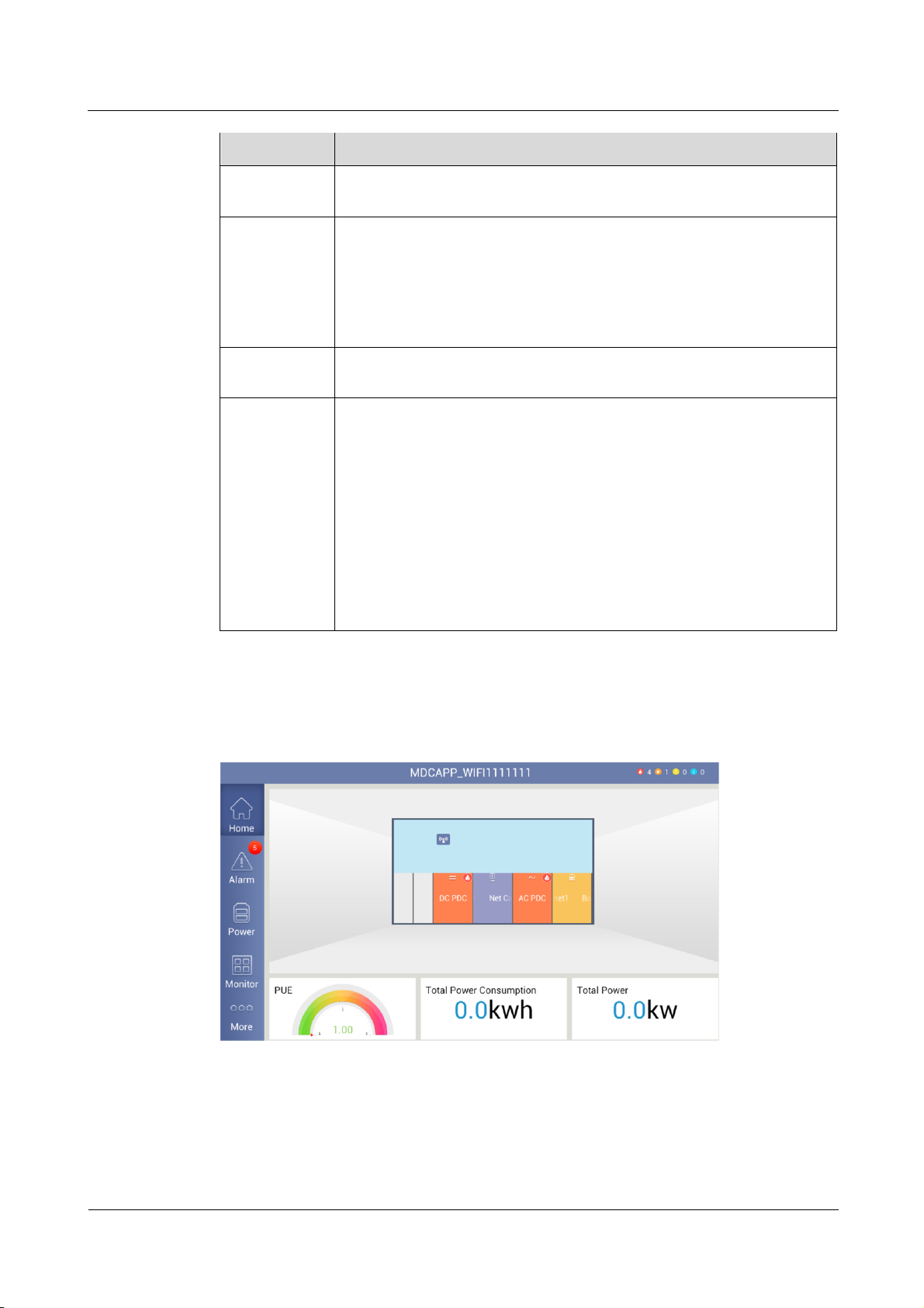
ECC800 Data Center Controller
User Manual
4 UI Description
Issue 02 (2019-02-28)
Copyright © Huawei Technologies Co., Ltd.
89
Screen
Function
Alarm
View active and historical alarms and search for alarms by a search
criterion.
Power
View the energy consumption data (such as the energy consumption of IT
equipment, smart cooling products, lights, and other devices) and PUE
change curves.
NOTE
The Power screen is displayed only when Enable PUE function is set to Yes on
the WebUI.
Monitor
Monitor the device running information in real time, set device running
parameters, and control the device running.
More View device asset details such as electronic labels of system devices
and other devices.
Modify the names and positions of devices in the device layout
diagram, and deliver a blinking command to a device under iFind.
View operation logs.
Upgrade software.
Maintain the system. For example, import and export data, view
network parameters, synchronize device parameters, and view the
version information.
Log out.
4.2.4 Pad App
Figure 4-9 Home
Page 99
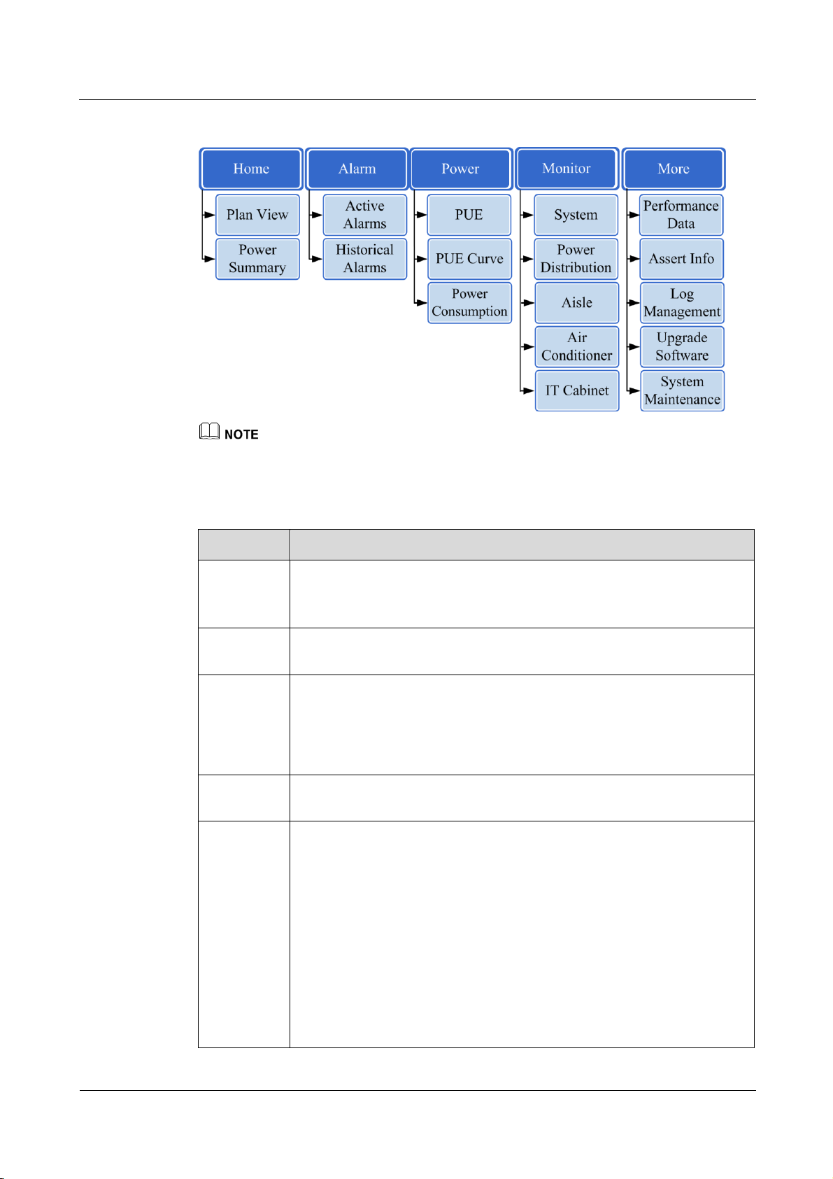
ECC800 Data Center Controller
User Manual
4 UI Description
Issue 02 (2019-02-28)
Copyright © Huawei Technologies Co., Ltd.
90
Figure 4-10 Pad app menu hierarchy
Screen
Function
Home View the device layout diagram, and tap a device icon in the layout
diagram to view the information configured for the device.
View the PUE, total power consumption, and total power.
Alarm
View active and historical alarms and search for alarms by a search
criterion.
Power
View the current PUE information, PUE change curve, and power
consumption of devices.
NOTE
The Power screen is displayed only when Enable PUE function is set to Yes on the
WebUI.
Monitor
Monitor the device running information in real time, set device running
parameters, and control the device running.
More View device asset details such as electronic labels of system devices and
other devices.
Modify the names and positions of devices in the device layout diagram,
and deliver a blinking command to a device under iFind.
View performance data, such as temperature and humidity, battery, and
discharge curves.
View operation logs.
Upgrade software.
Maintain the system. For example, view the version information, import
or export a configuration file, view network parameters, synchronize
device parameters, and log out.
The actual menu hierarchy prevails.
Table 4-5 Pad app functions
Page 100

ECC800 Data Center Controller
User Manual
5 Power-On Commissioning
Issue 02 (2019-02-28)
Copyright © Huawei Technologies Co., Ltd.
91
Prerequisites
5 Power-On Commissioning
The hardware and cable installation check is complete for controller components
according to data center specifications and requirements.
The device and ECC800 have been powered on.
You have obtained the ECC800 IP address as well as the user name and password used
for WebUI login.
A PC with an IP address in the same network segment as the ECC800 IP address is
prepared, and the PC has connected to the WAN_1 port on the ECC800.
Context
After installing or replacing the device or ECC800, set monitoring parameters and add the
device.
5.1 Setting the Date and Time
Procedure
Step 1 Choose System Settings > Time Settings.
Step 2 Set the time zone, date, and time, and click Submit.
Step 3 (Optional) If the NTP server is used for time synchronization, select NTP Server Sync, set
NTP Primary Server IP, NTP Backup Server IP, Port Number, and Sync Interval (Min),
and click Submit.
----End
 Loading...