

Page 1
eAN3810A
V100R001C00
Product Document
Issue
01
Date
2017-05-10
HUAWEI TECHNOLOGIES CO., LTD.
Page 2

Issue 01 (2017-05-10)
Huawei Proprietary and Confidential
Copyright © Huawei Technologies Co., Ltd.
i
Copyright © Huawei Technologies Co., Ltd. 2016. All rights reserved.
No part of this document may be reproduced or transmitted in any form or by any means without
prior written consent of Huawei Technologies Co., Ltd.
Trademarks and Permissions
and other Huawei trademarks are trademarks of Huawei Technologies Co., Ltd.
All other trademarks and trade names mentioned in this document are the property of their
respective holders.
Notice
The purchased products, services and features are stipulated by the contract made between
Huawei and the customer. All or part of the products, services and features described in this
document may not be within the purchase scope or the usage scope. Unless otherwise specified
in the contract, all statements, information, and recommendations in this document are provided
"AS IS" without warranties, guarantees or representations of any kind, either express or implied.
The information in this document is subject to change without notice. Every effort has been made
in the preparation of this document to ensure accuracy of the contents, but all statements,
information, and recommendations in this document do not constitute a warranty of any kind,
express or implied.
Huawei Technologies Co., Ltd.
Address:
Huawei Industrial Base
Bantian, Longgang
Shenzhen 518129
People's Republic of China
Website:
http://www.huawei.com
Email:
support@huawei.com
Page 3

Issue 01 (2017-05-10)
Huawei Proprietary and Confidential
Copyright © Huawei Technologies Co., Ltd.
2
Contents
1 Library Information
1.1 Library Changes
1.2 About HedEx Lite
1.3 How to Obtain and Update Documentation
1.4 Feedback
2 Safety
2.1 Health and Safety
2.1.1 General Instructions
2.1.2 Electrical Safety
2.1.3 Inflammable Environment
2.1.4 Working at Heights
2.1.4.1 Hoisting heavy objects
2.1.4.2 Using Ladders
2.1.5 Mechanical Safety
2.2 Equipment Safety
2.2.1 General Instructions
2.2.2 Electrical Safety
2.2.3 Inflammable Environment
2.2.4 Battery
2.2.4.1 Storage Battery
2.2.4.2 Lithium Battery
2.2.5 Mechanical Safety
2.2.6 Others
3 Description
3.1 eAN3810A Product Description
3.1.1 Introduction
3.1.1.1 Positioning
3.1.1.2 Benefits
3.1.2 Architecture
3.1.2.1 Network Architecture and Topologies
3.1.2.2 Hardware Appearance
3.1.2.3 Logical Structure
3.1.3 Operation and Maintenance
3.1.3.1 O&M Modes
3.1.3.2 O&M Functions
3.1.4 Technical Specifications
3.1.4.1 RF Specifications
3.1.4.2 Capacity Specifications
3.1.4.3 Output Power
3.1.4.4 Equipment Specifications
Page 4

Issue 01 (2017-05-10)
Huawei Proprietary and Confidential
Copyright © Huawei Technologies Co., Ltd.
3
3.1.4.5 Environment Specifications
3.1.4.6 Protocols and Standards Compliance
3.2 eAN3810A Hardware Description
3.2.1 eAN3810A Equipment
3.2.1.1 eAN3810A Exterior
3.2.1.2 eAN3810A Ports
3.2.1.3 eAN3810A Indicators
3.2.2 Auxiliary Devices
3.2.2.1 PSE
3.2.2.2 Dock
3.2.3 Mounting Kits
3.2.3.1 eAN3810A Mounting Kits
3.2.3.2 Dock Mounting Kits
3.2.4 Cables
3.2.4.1 Cable List
3.2.4.2 Ethernet Cable
3.2.4.3 PGND cable
3.2.4.4 RF Jumper
3.2.4.5 RGPS Signal Cable
3.3 eAN3810A Security Management Description
3.3.1 Security Overview
3.3.2 Transmission Security
3.3.2.1 Transmission Security Overview
3.3.2.2 DTLS
3.3.2.3 IPsec
3.3.2.4 PKI
3.3.2.5 SSL
3.3.2.6 Radio Security
3.3.3 OM Security
3.3.4 Equipment Security
3.3.5 Reference Information
3.3.5.1 User Name and Default Password
4 Installation and commissioning
4.1 eAN3810A Hardware Installation Guide
4.1.1 Installation Preparations
4.1.1.1 Reference Documents
4.1.1.2 Tools and Instruments
4.1.1.3 Requirements for Installation Personnel
4.1.2 Information About the Installation
4.1.2.1 Hardware Device Information
4.1.2.2 Installation Options and Restrictions
4.1.2.3 Installation Clearance and Space Requirements
4.1.2.4 Installation Environment Requirements
Page 5

Issue 01 (2017-05-10)
Huawei Proprietary and Confidential
Copyright © Huawei Technologies Co., Ltd.
4
4.1.3 Unpacking the Equipment
4.1.4 Installation Process
4.1.5 Obtaining the ESN
4.1.6 (Optional) Installing a Micro SD Card
4.1.7 Installing the eAN3810A
4.1.7.1 Installing eAN3810A on a Pole
4.1.7.2 Installing eAN3810A on a Wall
4.1.8 Installing the Auxiliary Devices
4.1.8.1 (Optional) Installing a Dock
4.1.8.1.1 Installing a Dock on a Pole
4.1.8.1.2 Installing a Dock on a Wall
4.1.8.2 (Optional) Installing the PSE
4.1.9 Installing Cables
4.1.9.1 Cabling Requirements
4.1.9.2 Cable Connections
4.1.9.3 Installing a PGND Cable
4.1.9.4 Installing a RF Jumper
4.1.9.5 Installing an Ethernet Cable
4.1.9.6 (Optional) Installing the PSE Cable
4.1.9.7 (Optional) Installing the Dock Ethernet Cable
4.1.9.8 (Optional) Installing the Dock Power Cable
4.1.10 Checking Hardware Installation
4.1.11 Power-On Check on the eAN3810A
4.1.12 Appendix
4.1.12.1 ESN Collection Template
4.1.12.2 Antenna Installation
4.2 eAN3810A Deployment Guide
4.2.1 MicroSD Card Site Deployment
4.2.1.1 Introduction to Deployment Modes
4.2.1.1.1 Site Deployment Overview
4.2.1.1.2 Deployment Process
4.2.1.2 Deployment Preparation
4.2.1.2.1 Preparation for Site Deployment
4.2.1.2.1.1 Preparing Common Base Station Deployment Data Files on the CME
4.2.1.2.1.1.1 Data Configuration Process
4.2.1.2.1.1.2 Data Preparation
4.2.1.2.1.1.3 Creating a Work Area
4.2.1.2.1.1.4 Configuring Data on GUIs
4.2.1.2.1.1.4.1 Creating Base Stations
4.2.1.2.1.1.4.2 Configuring eAN3810A Data
4.2.1.2.1.1.5 Verifying Data
4.2.1.2.1.1.6 Exporting Configuration Files
4.2.1.2.1.1.6.1 Exporting the Deployment Lists and Configuration Files of Base Stations
Page 6

Issue 01 (2017-05-10)
Huawei Proprietary and Confidential
Copyright © Huawei Technologies Co., Ltd.
5
4.2.1.2.1.2 Preparing an SD Card
4.2.1.2.1.3 Checking a Transport Network
4.2.1.2.1.4 Checking the SD Card Port Status
4.2.1.2.1.5 Preparing Dialing Test Tools
4.2.1.3 Hardware installation check phase
4.2.1.3.1 Hardware Installation and Power-on Check
4.2.1.4 Engineering Verification
4.2.1.4.1 Verification for Site Deployment
4.2.1.4.1.1 Viewing Deployment Results at Sites
4.2.1.4.1.2 Viewing Deployment Results on the U2000
4.2.1.4.1.3 Handling Alarms
4.2.1.4.1.4 Disabling the SD Card Port
4.2.1.4.1.5 Verifying Services
4.2.1.5 FAQ
4.2.1.5.1 How Do I Set the U2000 Client Display Style?
4.2.1.5.2 How Do I Prepare a Precfg.ini File?
4.2.1.5.3 Directory Structure on a MicroSD Card
4.2.1.5.4 Integrity and Encryption Protection on Files in MicroSD Cards
4.2.1.5.4.1 Applying Integrity and Encryption Protection to Files in a Single MicroSD Card
4.2.1.5.4.2 Applying Integrity and Encryption Protection to Files in Multiple SD Cards
4.2.1.5.5 Saving Alarms/Events
4.2.2 MML Site Deployment
4.2.2.1 Configuration Reference
4.2.2.1.1 Initial Configuration Using the LMT
5 Operation and Maintenance
5.1 General
5.1.1 eAN3810A LMT User Guide
5.1.1.1 Introduction to the LMT
5.1.1.1.1 Definitions of the LMT
5.1.1.1.2 Functions of the LMT
5.1.1.1.3 System Requirements for LMT Installation
5.1.1.1.4 Components of the LMT Main Window
5.1.1.2 Getting Started with the LMT
5.1.1.2.1 Logging In to the LMT
5.1.1.2.2 Logging Out of the LMT
5.1.1.2.3 Managing User Accounts
5.1.1.3 Running MML Commands
5.1.1.3.1 Basic Concepts Related to MML Commands
5.1.1.3.2 Running a Single MML Command
5.1.1.3.3 Setting Parameters
5.1.1.4 Managing Alarms/Events
5.1.1.4.1 Basic Concepts Related to Alarms/Events
5.1.1.4.2 Handling Alarms/Events
Page 7

Issue 01 (2017-05-10)
Huawei Proprietary and Confidential
Copyright © Huawei Technologies Co., Ltd.
6
5.1.1.4.2.1 Setting Alarm/Event Query Properties
5.1.1.4.2.2 Browsing Active Alarms/Events
5.1.1.4.2.3 Querying Alarm/Event Logs
5.1.1.4.2.4 Saving Alarms/Events
5.1.1.4.2.5 Querying Alarm/Event Handling Suggestions
5.1.1.4.2.6 Manually Refreshing Alarms/Events
5.1.1.4.2.7 Manually Clearing Alarms/Events
5.1.1.4.2.8 Deleting Cleared Alarms/Events
5.1.1.5 Managing Message Tracing
5.1.1.5.1 Basic Concepts Related to Message Tracing
5.1.1.5.2 General Operations Related to Message Tracing
5.1.1.5.2.1 Browsing Traced Messages Online
5.1.1.5.2.2 Viewing the Interpretation of Traced Messages
5.1.1.5.2.3 Saving Traced Messages
5.1.1.5.3 Interface Trace
5.1.1.5.3.1 MAC Trace
5.1.1.5.3.2 IP Layer Protocol Trace
5.1.1.5.3.3 CMPV2 Trace
5.1.1.5.3.4 IKE Trace
5.1.1.5.3.5 PNP Trace
5.1.1.6 FAQ
5.1.1.6.1 Functions of the LMT Becoming Abnormal After an LMT Version Upgrade or Rollback
5.1.1.6.2 Slow Responses in the Firefox Browser
5.1.1.6.3 LMT Colors Cannot Be Displayed
5.1.1.6.4 No Response When Clicking the Menu Bar on the LMT
5.1.1.6.5 How to Rectify Errors That Occurr While Saving a File
5.1.1.6.6 What Do I Do to Avoid the Failure to Log In to the LMT Due to a High Default Internet
Explorer Security Level
5.1.1.6.7 What Do I Do to Handle the Slow Redirection When Logging in to the LMT
5.1.1.6.8 What Do I Do to Handle the LMT Interface Disorder
5.1.1.6.9 What Do I Do to Handle the Unknown Error Occurring on LMT Interface or the MML
Command Execution Failure After a Browser Upgrade
5.1.1.6.10 What Do I Do to Handle the Interface Display Failure or Error Message Displayed on the
LMT
5.1.1.6.11 A "This user session already exists" Error Message Is Displayed During LMT Login
5.1.1.6.12 How to Install OS Patches
5.1.1.6.13 What Do I Do if Tracing Function Cannot Be Used?
5.1.1.6.14 What Do I Do If There Is No Response or Any Error Message After a Tracing Task Is
Created
5.1.1.6.15 How to Handle the Problem That Only the Error Code Is Displayed in an Error Message
After a Tracing Task Is Created
5.1.1.6.16 Any Further Operation Performed When Some LMT Web Pages Fail to Update Causes
the Web Pages to Turn Blank
5.1.1.6.17 How to Handle the LMT Exit After Clicking Trace, Monitor, or Device Maintenance Tab
in Window 7
Page 8

Issue 01 (2017-05-10)
Huawei Proprietary and Confidential
Copyright © Huawei Technologies Co., Ltd.
7
5.1.1.6.18 How to Handle Exceptions in the LMT Due to Insufficient PC Memory
5.1.1.6.19 Interfaces for Performing Tracing Task Blinking
5.1.1.6.20 How to Handle Shortcut Key Invalidation
5.1.1.6.21 What Do I Do If A Message "Stop running this script?" Is Displayed?
5.1.1.6.22 The Internet Explorer Fails to Respond or the Login Window Is Displayed After the LMT
Is Running for a While or Multiple Functions Are Concurrently Enabled on the LMT
5.1.1.6.23 A Message checking client environment... Is Displayed on the Login Window and the
browser Does Not Respond
5.1.1.6.24 LMT Login Window Being Stopped by the Browser
5.1.1.6.25 The Application Blocked by Security Settings Dialog Box Is Displayed When executes
man-machine language (MML) commands, manages alarms and events, traces messages Is Enabled
5.1.1.6.26 Help for Installing and Using the Java Plug-in
5.1.1.6.27 What Do I Do If the Message Your Java version is out of date Is Displayed?
5.1.1.6.28 How to Configure Wireless NIC on a Computer
5.1.1.6.29 Ghosting Occurring on the WebLMT Window That Is Opened Using an IE11 Web
Browser
Page 9

Issue 01 (2017-05-10)
Huawei Proprietary and Confidential
Copyright © Huawei Technologies Co., Ltd.
8
1 Library Information
Library Changes
Updates between document versions are cumulative. Therefore, the latest document
version contains all updates made to previous versions.
About HedEx Lite
HedEx Lite is the latest product documentation management system released by
Huawei. HedEx Lite is installation-free, lightweight, and provides the global
search feature.
How to Obtain and Update Documentation
This chapter describes how to obtain and update the documentation.
Feedback
This chapter describes how to feedback suggestions and comments of the Huawei
documentation.
Notice: This equipment has been tested and found to comply with the limits for a Class B digital device,
pursuant to part 15 of the FCC Rules. These limits are designed to provide reasonable protection against
harmful interference in a residential installation. This equipment generates, uses and can radiate radio
frequency energy and, if not installed and used in accordance with the instructions, may cause harmful
interference to radio communications. However, there is no guarantee that interference will not occur in a
particular installation. If this equipment does cause harmful interference to radio or television reception,
which can be determined by turning the equipment off and on, the user is encouraged to try to correct
the interference by one or more of the following measures:
—Reorient or relocate the receiving antenna.
—Increase the separation between the equipment and receiver.
—Connect the equipment into an outlet on a circuit different from that to which the receiver is connected.
—Consult the dealer or an experienced radio/TV technician for help.
MODIFICATION: Any changes or modifications not expressly approved by the grantee of this device
could void the user’s authority to operate the device.
This device should be installed and operated with a minimum distance of 20cm between the antenna
and all persons.
1.1 Library Changes
Page 10
Issue 01 (2017-05-10)
Huawei Proprietary and Confidential
Copyright © Huawei Technologies Co., Ltd.
9
Updates between document versions are cumulative. Therefore, the latest document
version contains all updates made to previous versions.
Issue 01 (2017-03-30)
This issue is the first commercial release.
Parent topic: Library Information
1.2 About HedEx Lite
HedEx Lite is the latest product documentation management system released by
Huawei. HedEx Lite is installation-free, lightweight, and provides the global
search feature.
HedEx Lite is the latest product documentation management system released by
Huawei. HedEx Lite does not require installation. It is lightweight and provides
the global search feature. It is compatible with HedEx V100R002.
NOTE:
Huawei product documentation is delivered in HDX format. HDX is a compressed file format, which
supports browsing of HTML and PDF files using HedEx.
How to Obtain
You can obtain HedEx Lite by means of:
HedEx Lite download link provided at http://support.huawei.com/enterprise
Basic Functions
HedEx Lite manages electronic documentation for different Huawei products and
software versions in a centralized manner. It provides the following functions:
document browsing, searching, printing, bookmark, commenting, feedback,
documentation package management, and automatic upgrade of documentation package
and software. For details, see the online Help of HedEx Lite.
Features
Secure and installation-free
HedEx Lite does not need to be installed. It requires only a small amount of
disk space and memory.
Integrated browse window
Page 11

Issue 01 (2017-05-10)
Huawei Proprietary and Confidential
Copyright © Huawei Technologies Co., Ltd.
10
HedEx Lite enables you to browse documents of different products and software
versions in one window.
Easy access to latest documentation
Using HedEx Lite, you can:
Download documentation of any version.
Update your local documentation package anytime.
Specify an interval for automatic update of your local documentation
package.
Highly compatible
HedEx Lite runs on mainstream Windows operating systems and supports browsers
such as Internet Explorer, Mozilla Firefox, Apple Safari, and Google Chrome.
Highly secure
Application-level access control: HedEx Lite accepts only connection
requests from local loopback IP address (127.0.0.1). Connection requests
from any other IP address will be rejected.
System-level network protection: HedEx Lite complies with firewall access
control polices of customers. It can run behind the firewall provided by
Windows or a third-party firewall.
Security protection for documentation package update: Strict approval
process is applied to ensure that documents uploaded to
http://support.huawei.com/enterprise do not contain any executable codes.
Security protection for software upgrade: Strict approval process is
applied to ensure that the HedEx Lite software package uploaded to
http://support.huawei.com/enterprise is complete and legitimate.
Parent topic: Library Information
1.3 How to Obtain and Update Documentation
This chapter describes how to obtain and update the documentation.
NOTE:
To use HedEx Lite or to log in to Huawei technical support website, you need a registered user
account. You can apply for a user account at http://support.huawei.com/enterprise or apply for an
account by contacting the service manager of your local Huawei office.
Page 12

Issue 01 (2017-05-10)
Huawei Proprietary and Confidential
Copyright © Huawei Technologies Co., Ltd.
11
Obtaining Documentation
You can obtain CPI documents in the following ways:
Use the online search function provided by HedEx Lite to find the
documentation package you want and download it. This method is recommended
because you can directly load the desired documentation package to HedEx Lite.
For details about how to load a documentation package, see the online Help of
HedEx Lite.
Download the desired documentation package from http://support.huawei.com/enterprise.
Updating Documentation
You can update CPI documents in the following ways:
Enable the library upgrade function provided by HedEx Lite. This method is
recommended because HedEx Lite can automatically detect the latest version
for your local documentation packages and prompt you to conduct an upgrade.
For details about how to enable the library upgrade function, see the online
Help of HedEx Lite.
Download the latest documentation packages from http://support.huawei.com/enterprise.
Parent topic: Library Information
1.4 Feedback
This chapter describes how to feedback suggestions and comments of the Huawei
documentation.
Huawei welcomes your suggestions and comments. You can provide your feedback to
us in any of the following ways:
Call the service hotline of your local Huawei office.
Send an email to support_e@huawei.com.
Use the feedback function provided by HedEx Lite to send your suggestions to
support_e@huawei.com. For details about how to use the feedback function, see the
online Help of HedEx Lite.
Parent topic: Library Information
Page 13
Issue 01 (2017-05-10)
Huawei Proprietary and Confidential
Copyright © Huawei Technologies Co., Ltd.
12
2 Safety
This section provides the health and safety, equipment safety instructions that
you must follow when installing, operating, and maintaining devices.
Health and Safety
This section provides the health and safety instructions that you must follow
when installing, operating, and maintaining Huawei devices.
Equipment Safety
This section provides the safety instructions that you must follow when
installing, operating, and maintaining Huawei devices.
2.1 Health and Safety
This section provides the health and safety instructions that you must follow
when installing, operating, and maintaining Huawei devices.
General Instructions
This section describes the safety precautions you must take before installing or
maintaining Huawei equipment.
Electrical Safety
This section provides safety instructions for high voltage, high leakage current,
and power cables.
Inflammable Environment
This section provides safety instructions for operations in an air environment
where devices are operating.
Working at Heights
This section provides safety instructions for working at heights.
Mechanical Safety
This section provides safety instructions for drilling holes, handling sharp
objects, operating fans, and carrying heavy objects.
Parent topic: Safety
2.1.1 General Instructions
Page 14

Issue 01 (2017-05-10)
Huawei Proprietary and Confidential
Copyright © Huawei Technologies Co., Ltd.
13
This section describes the safety precautions you must take before installing or
maintaining Huawei equipment.
All Safety Instructions
To ensure safety of humans and the equipment, pay attention to the safety
symbols on the equipment and all the safety instructions in this document.
The "CAUTION", "WARNING", and "DANGER" are only supplements to the safety
instructions.
Local Laws and Regulations
When operating the device, you must follow the local laws and regulations. The
safety instructions in this document are only supplements to the local laws and
regulations.
Basic Installation Requirements
Only professional or qualified personnel are allowed to install, operate, and
maintain the equipment.
Only qualified and professional personnel are allowed to dismantle security
facilities and troubleshoot the equipment.
Only the personnel authenticated or authorized by Huawei are allowed to
replace or change the device or the parts of the device (including the
software).
The operator must report the faults or errors that may cause safety problems
to the person in charge of the device immediately.
Personal Safety
Requirements for operations in thunderstorms are:
Do not operate the device or cables.
Disconnect the AC power connectors.
Do not use fixed terminals.
Do not touch terminal or antenna connectors.
NOTE:
The preceding requirements apply to wireless fixed station terminals.
Page 15
Issue 01 (2017-05-10)
Huawei Proprietary and Confidential
Copyright © Huawei Technologies Co., Ltd.
14
To prevent electric shock, do not connect the connector of a safety extra-low
voltage (SELV) circuit to the connector of a telecommunication network
voltage (TNV) circuit.
Do not look into the optical interfaces without eye protection. Otherwise,
human eyes may be hurt by laser beams.
Before operating the device, make sure that you:
Wear ESD clothes.
Wear ESD gloves and wrist strap.
Take off the conductive stuff such as watches, bracelets and rings to avoid
being shocked.
In case of fire, escape from the building or site where the device is located
and press the fire alarm bell or dial the telephone number for fire alarms.
Entering the burning building again is prohibited in any situation.
Parent topic: Health and Safety
2.1.2 Electrical Safety
This section provides safety instructions for high voltage, high leakage current,
and power cables.
High Voltage
DANGER:
The high voltage power supply provides power for device operations. Touching
the high voltage power supply directly or indirectly through damp objects may
cause fatal hazards.
Operating the high voltage power supply incorrectly or irregularly may cause
accidents such as fire or electric shock.
High Leakage Current
NOTICE:
Before powering on a device, ground the device. Otherwise, the safety of humans
cannot be ensured.
Page 16
Issue 01 (2017-05-10)
Huawei Proprietary and Confidential
Copyright © Huawei Technologies Co., Ltd.
15
If a high leakage current mark is labelled near the power connector of the
device, you must connect the protection grounding terminal on the device housing
to the ground before connecting the device to an A/C input power supply. This is
to prevent the electric shock caused by the leakage current of the device.
Power Cables
DANGER:
Installing or removing power cables when the device is on is prohibited. This is
because when the cores of power cables contact conductors, electric arcs or
sparks are generated, which may cause fire or hurt human eyes.
Before installing or removing power cables, you must power off the device.
Before connecting a power cable, you must check that the label on the power
cable is correct.
Parent topic: Health and Safety
2.1.3 Inflammable Environment
This section provides safety instructions for operations in an air environment
where devices are operating.
DANGER:
Do not place the device in an environment that has inflammable and explosive air
or gas. Do not perform any operation in this environment.
Parent topic: Health and Safety
2.1.4 Working at Heights
This section provides safety instructions for working at heights.
CAUTION:
Avoid object falling when you work at heights.
Page 17
Issue 01 (2017-05-10)
Huawei Proprietary and Confidential
Copyright © Huawei Technologies Co., Ltd.
16
When working at heights, fulfill the following requirements:
Only trained personnel can work at heights.
Prevent the devices and tools that you carry from falling down.
Take safety and protection measures, for example, wear a helmet and safety
belt.
Wear warm clothes when working at heights in a cold region.
Before working at heights, check that all the lifting facilities are in good
condition.
Hoisting heavy objects
This section provides safety instructions for hoisting heavy objects that you
must follow when installing, operating, and maintaining Huawei devices.
Using Ladders
This section provides safety instructions for using ladders.
Parent topic: Health and Safety
2.1.4.1 Hoisting heavy objects
This section provides safety instructions for hoisting heavy objects that you
must follow when installing, operating, and maintaining Huawei devices.
CAUTION:
Do not walk below the cantilever or hoisted objects when heavy objects are being
hoisted.
Only trained and qualified personnel can perform hoisting operations.
Before hoisting heavy objects, check that the hoisting tools are complete and
in good condition.
Before hoisting heavy objects, ensure that the hoisting tools are fixed to a
secure object or wall with good weight capacity.
Issue orders with short and explicit words to avoid misoperations.
Ensure that the angle formed by two cables is not larger than 90 degrees.
Parent topic: Working at Heights
Page 18
Issue 01 (2017-05-10)
Huawei Proprietary and Confidential
Copyright © Huawei Technologies Co., Ltd.
17
2.1.4.2 Using Ladders
This section provides safety instructions for using ladders.
Checking Ladders
Before using a ladder, check whether the ladder is damaged. Only the ladder
in good condition can be used.
Before using a ladder, you should know the maximum weight capacity of the
ladder. Avoid overweighing the ladder.
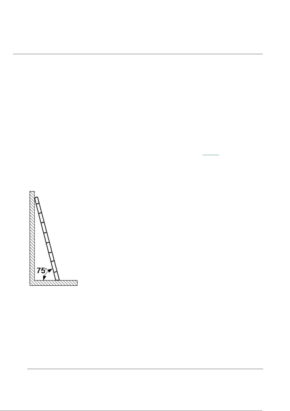
Placing Ladders
The recommended gradient of the ladder is 75 degrees. You can measure the
gradient of the ladder with an right angle or your arm. See Figure 1. When using a
ladder, ensure that the wider feet of the ladder are downward, or take
protection measures for the ladder feet to prevent the ladder from sliding.
Ensure that the ladder is placed securely.
Figure 1 Leaning a ladder
Climbing Up a Ladder
When climbing up a ladder, note the following :
Ensure that the center of gravity of your body does not deviate from the
edges of the two long sides.
To minimize the risk of falling, hold your balance on the ladder before any
operation.
Page 19
Issue 01 (2017-05-10)
Huawei Proprietary and Confidential
Copyright © Huawei Technologies Co., Ltd.
18
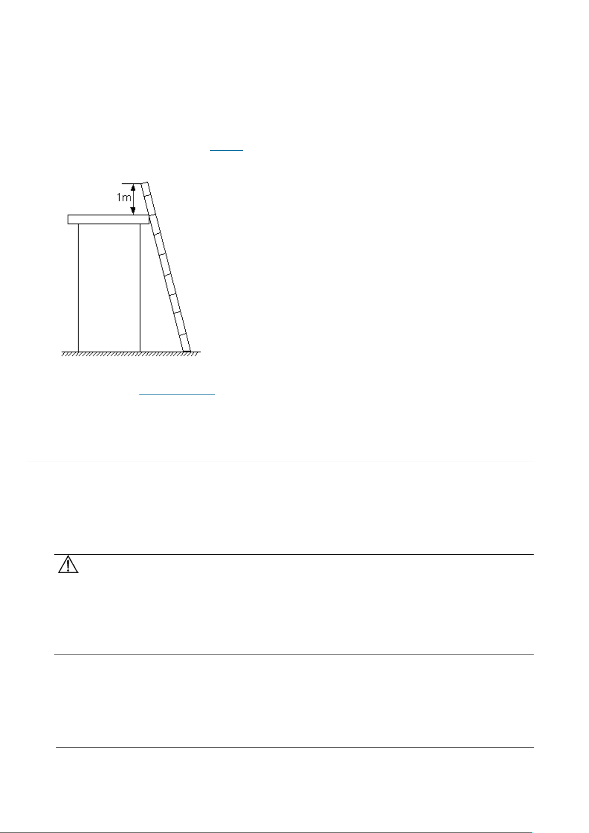
Do not climb higher than the fourth rung of the ladder (counted from up to
down).
If you want to climb up a roof, ensure that the ladder top is at least one meter
higher than the roof. See Figure 2.
Figure 2 Ladder top being one meter higher than the roof
Parent topic: Working at Heights
2.1.5 Mechanical Safety
This section provides safety instructions for drilling holes, handling sharp
objects, operating fans, and carrying heavy objects.
Drilling Holes
NOTICE:
Do not drill the cabinet at will. Drilling holes without complying with the
requirements may affect the electromagnetic shielding performance of the cabinet
and damage the cables inside the cabinet. In addition, if the scraps caused by
drilling enter the cabinet, the printed circuit boards (PCBs) may be short
circuited.
Wear an eye protector when drilling holes. This is to prevent the operator's
eyes from being injured by the splashing metal scraps.
Wear protection gloves when drilling holes.
Page 20
Issue 01 (2017-05-10)
Huawei Proprietary and Confidential
Copyright © Huawei Technologies Co., Ltd.
19
Sharp Objects
CAUTION:
Before you hold or carry a device, wear protective gloves to avoid getting
injured by sharp edges of the device.
Fans
When replacing the parts near fans, do not insert your fingers or boards into
the operating fans before the fans are switched off and stop running. Otherwise,
the hands of the operator can get hurted.
Carrying Heavy Objects
Wear protection gloves when carrying heavy objects. This is to prevent the
carrier's hands from being hurt.
CAUTION:
The carrier must be prepared for load bearing before carrying heavy objects.
This is to prevent the carrier from being strained or pressed by the heavy
objects.
When you pull a chassis out of the cabinet, pay attention to the unstable or
heavy objects on the cabinet. This is to prevent the heavy objects on the
cabinet top from falling down, which may hurt the operator.
Generally, two persons are needed to carry a chassis. It is prohibited that
only one person carries a heavy chassis. When carrying a chassis, the
carriers should stretch their backs and move stably to avoid being strained.
When moving or lifting a chassis, hold the handles or bottom of the chassis.
Do not hold the handles of the modules installed in the chassis, such as the
power modules, fan modules, and boards.
Parent topic: Health and Safety
2.2 Equipment Safety
This section provides the safety instructions that you must follow when
installing, operating, and maintaining Huawei devices.
Page 21

Issue 01 (2017-05-10)
Huawei Proprietary and Confidential
Copyright © Huawei Technologies Co., Ltd.
20
General Instructions
This section provides the general instructions for the installation, operation,
and maintenance of Huawei devices.
Electrical Safety
This section provides safety instructions for high voltage, high leakage current,
power cables, fuses, and electrostatic discharge (ESD).
Inflammable Environment
This section provides safety instructions for operations in an air environment
where devices are operating.
Battery
This section provides safety instructions for operations of storage batteries
and lithium ion batteries.
Mechanical Safety
This section provides safety instructions for hole drilling and fans.
Others
This section provides safety instructions for installing and removing boards,
binding signal cables, and handling cables at low temperature.
Parent topic: Safety
2.2.1 General Instructions
This section provides the general instructions for the installation, operation,
and maintenance of Huawei devices.
All Safety Instructions
To ensure the safety of humans and the device, follow the marks on the device
and all the safety instructions in this document.
The "CAUTION", "WARNING", and "DANGER" marks in this document are only
supplements to the safety instructions.
Local Laws and Regulations
When operating the device, you must follow the local laws and regulations. The
safety instructions in this document are only supplements to the local laws and
regulations.
Basic Installation Requirements
Page 22

Issue 01 (2017-05-10)
Huawei Proprietary and Confidential
Copyright © Huawei Technologies Co., Ltd.
21
Only professional or qualified personnel are allowed to install, operate, and
maintain the equipment.
Only qualified and professional personnel are allowed to dismantle security
facilities and troubleshoot the equipment.
Only the personnel certified or authorized by Huawei are allowed to replace
or change the device of the parts or the device (including the software).
The operator must report the faults or errors that may cause safety problems
to the person in charge of the device immediately.
Grounding Requirements
The following requirements only apply to the devices that need to be grounded.
When you install a device, you must ground it first. When you remove a device,
you must remove the ground cable at last.
Damaging grounding conductors is prohibited.
Operating a device before the grounding conductor is installed is prohibited.
Devices must be connected to the grounding earth permanently. Before
operating a device, check the electrical connection of the device and ensure
that the device is properly grounded.
Device Safety
Before operating the device, securely fix the device on the floor or another
stable object, for example, a wall or an installation rack.
Do not block the ventilation openings when the device is in operation.
When installing panels, you must use a proper tool to tighten the screws.
After installing the device, clear the package material from the site where
the device is installed.
Parent topic: Equipment Safety
2.2.2 Electrical Safety
This section provides safety instructions for high voltage, high leakage current,
power cables, fuses, and electrostatic discharge (ESD).
High Voltage
Page 23
Issue 01 (2017-05-10)
Huawei Proprietary and Confidential
Copyright © Huawei Technologies Co., Ltd.
22
DANGER:
Operating the high voltage power supply incorrectly or irregularly may cause
accidents such as fire or electric shock.
High Electrical Leakage
NOTICE:
Before powering on a device, ground the device. Otherwise, the safety of the
device cannot be ensured.
Power Cables
DANGER:
Installing or removing power cables when the device is on is prohibited. This is
because when the cores of power cables contact conductors, electric arcs or
sparks are generated, which may cause fire.
Before installing or removing the power cable, turn off the power switch.
Before connecting a power cable, check that the label on the power cable is
correct.
Fuses
NOTICE:
To ensure the safety of the device, when the fuse on the device is blown, you
must replace the blown fuse with a fuse of the same type and specification.
ESD
NOTICE:
The Static charge generated on human bodies may damage the electrostatic
sensitive devices (ESSDs) on boards, for example, large-scale integration (LSI)
integrated circuits (ICs).
Human body movement, friction between human bodies and clothes, friction
between shoes and floors, or handling of plastic articles causes static
electromagnetic fields on human bodies. These static electromagnetic fields
cannot be eliminated until the static is discharged.
To prevent electrostatic-sensitive components from being damaged by the
static on human bodies, you must wear a well-grounded ESD wrist strap when
Page 24
Issue 01 (2017-05-10)
Huawei Proprietary and Confidential
Copyright © Huawei Technologies Co., Ltd.
23
touching the device or handling boards or application-specific integrated
Table 1 Technical specifications of the ESD wrist strap
Item
Specification
Grounding resistance of the wrist strap,
expressed in ohms
The resistance should be not less than
0.75 x 10⁶ ohms and not greater than 10 x
106 ohms.
Resistance between the internal surface of
wrist strap and the wrist strap buckle,
expressed in ohms
The resistance should be less than or
equal to 20 x 103 ohms.
Resistance of the connecting cable of the
wrist strap, expressed in ohms
The resistance should be greater than 0.8
x 106 and less than 1.2 x 10⁶ ohms.
circuits (ASICs).
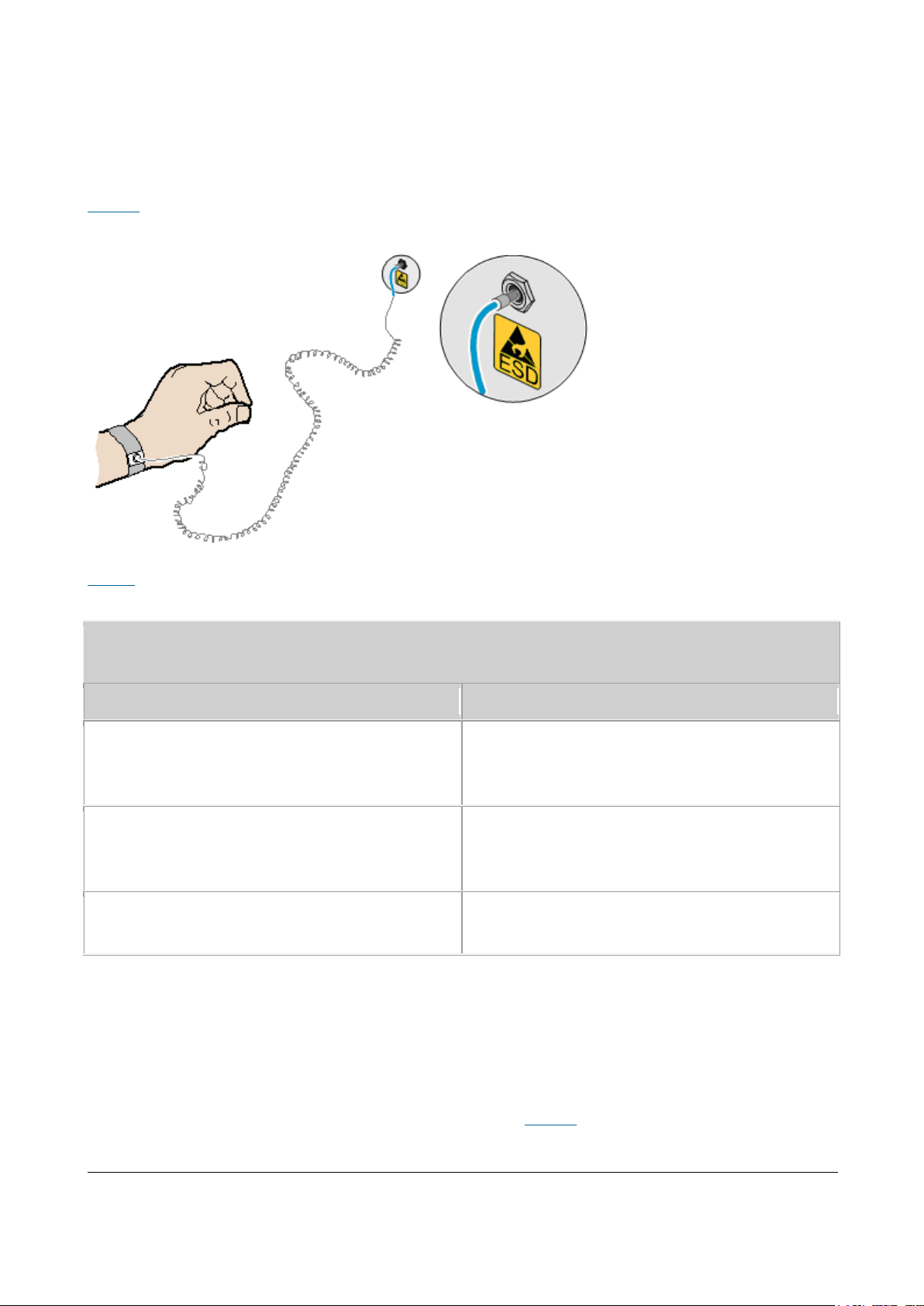
Figure 1 shows how to wear an ESD wrist strap.
Figure 1 Wearing an ESD wrist strap
Table 1 lists the technical specifications of the ESD wrist strap.
Test the ESD wrist strap periodically to keep it in good and ready to use
condition.
When an ESD wrist strap works normally, the resistance should be within the
range of 1 ohm to 10 ohms.
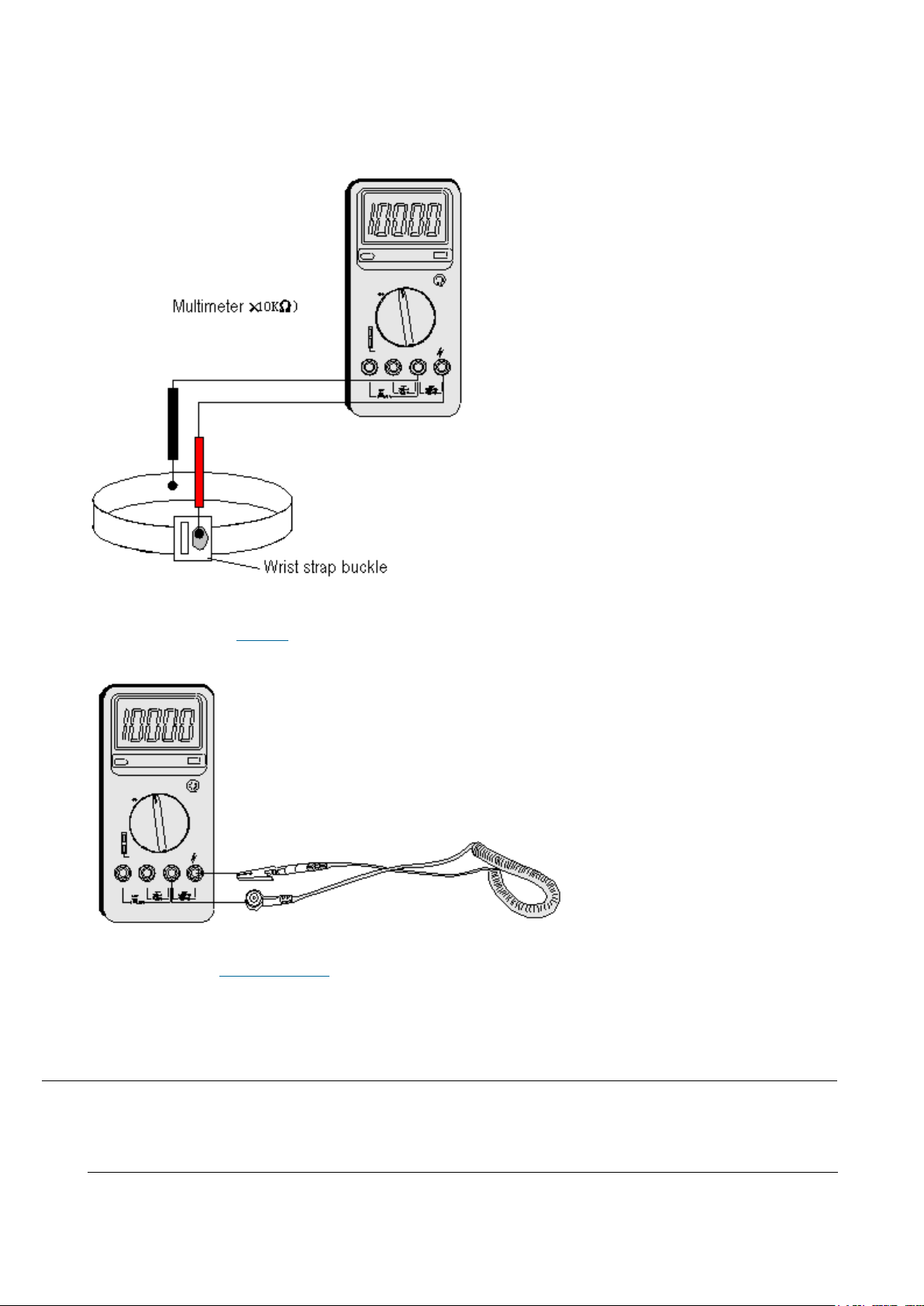
Measure the resistance between the internal surface of the ESD wrist strap and
the wrist strap buckle using a multimeter. See Figure 2.
Page 25
Issue 01 (2017-05-10)
Huawei Proprietary and Confidential
Copyright © Huawei Technologies Co., Ltd.
24
Figure 2 Measuring the resistance between the internal surface and the wrist strap
buckle using a multimeter
Measure the resistance of the connecting cable of the ESD wrist strap using a
multimeter. See Figure 3.
Figure 3 Measuring the resistance of the connecting cable using a multimeter
Parent topic: Equipment Safety
2.2.3 Inflammable Environment
This section provides safety instructions for operations in an air environment
where devices are operating.
Page 26
Issue 01 (2017-05-10)
Huawei Proprietary and Confidential
Copyright © Huawei Technologies Co., Ltd.
25
DANGER:
Do not place the device in an environment that has inflammable and explosive air
or gas. Do not perform any operation in this environment.
Operating an electronic device in an environment of flammable air causes a
severe hazard.
Parent topic: Equipment Safety
2.2.4 Battery
This section provides safety instructions for operations of storage batteries
and lithium ion batteries.
Storage Battery
This section provides safety instructions for operations of storage batteries.
Lithium Battery
This section provides safety instructions for operations of lithium ion
batteries.
Parent topic: Equipment Safety
2.2.4.1 Storage Battery
This section provides safety instructions for operations of storage batteries.
Irregular operations of the storage battery cause hazards. When operating the
storage battery, you must avoid short circuit and overflow or loss of the
electrolyte.
Overflow of the electrolyte brings potential hazards to the device because
the overflowing electrolyte erodes the metals and boards and damages the
boards.
Basic Precautions
To ensure safety, note the following points before installing or maintaining the
storage battery:
Page 27
Issue 01 (2017-05-10)
Huawei Proprietary and Confidential
Copyright © Huawei Technologies Co., Ltd.
26
Use special insulation tools.
When handling the storage battery, ensure that its electrodes are upward.
Leaning or reversing the storage battery is prohibited.
Before installing or maintaining the storage battery, ensure that the storage
battery is disconnected from the power supply that charges the storage
battery.
Short Circuit
CAUTION:
Battery short circuit may cause human injuries. Although the voltage of ordinary
batteries is low, the instantaneous high current caused by the short circuit
releases a great deal of energy.
Avoid short circuit of batteries caused by metal objects. If possible,
disconnect working batteries before the other operations.
Hazardous Gas
NOTICE:
Using unsealed lead acid storage batteries is prohibited. Lead acid storage
batteries must be placed horizontally and stably to prevent the batteries from
releasing flammable gas, which may cause fire or erode the device.
Working lead acid storage batteries release flammable gas. Therefore,
ventilation and fireproofing measures must be taken at the sites where lead acid
storage batteries are placed.
Battery Temperature
NOTICE:
If a battery overheats, the battery may be deformed or damaged, and the
electrolyte may overflow.
When the temperature of the battery is higher than 60°C (140°F), you need to
check whether the electrolyte overflows. If the electrolyte overflows, you can
use Battery Leakage to absorb and counteract the leaking electrolyte.
Battery Leakage
CAUTION:
Page 28
Issue 01 (2017-05-10)
Huawei Proprietary and Confidential
Copyright © Huawei Technologies Co., Ltd.
27
When the electrolyte overflows, absorb and counteract the electrolyte
immediately.When moving or handling a battery whose electrolyte leaks, note that
the leaking electrolyte may hurt human bodies.
When you find the electrolyte leaks, Select a substance to absorb and counteract
the leaking electrolyte according to the instructions of the battery
manufacturer.
Parent topic: Battery
2.2.4.2 Lithium Battery
This section provides safety instructions for operations of lithium ion
batteries.
CAUTION:
Replacing a lithium ion battery with a lithium ion battery of another model may
cause explosion.
You can replace a lithium ion battery only with a lithium ion battery of a
model recommended by the manufacturer.
Exhausted lithium ion batteries must be disposed of according to the
instructions.
Do not throw lithium ion batteries into fire.
Parent topic: Battery
2.2.5 Mechanical Safety
This section provides safety instructions for hole drilling and fans.
Drilling Holes
NOTICE:
Do not drill the cabinet at will. Drilling holes without complying with the
requirements may affect the electromagnetic shielding performance of the cabinet
Page 29
Issue 01 (2017-05-10)
Huawei Proprietary and Confidential
Copyright © Huawei Technologies Co., Ltd.
28
and damage the cables inside the cabinet. In addition, if the scraps caused by
drilling enter the cabinet, the printed circuit boards (PCBs) may be short
circuited.
Before drilling holes in a cabinet, move the cables inside the cabinet away
from the drilling positions.
Prevent metal scraps from falling into the cabinet. After drilling holes,
clear the metal scraps.
Fans
When replacing parts, place the objects such as the parts, screws, and tools
properly. This is to prevent them from falling into the operating fans, which
damages the fans or device.
Parent topic: Equipment Safety
2.2.6 Others
This section provides safety instructions for installing and removing boards,
binding signal cables, and handling cables at low temperature.
Installing and Removing Boards
NOTICE:
Before installing a board, you need to wear an electrostatic discharge (ESD)
wrist strap and ESD gloves. When installing the board, use proper force to
prevent the pins on the backplane from being leaned.
To ensure all the boards are running properly, Installing and Removing Boards
must fulfill the following requirements:
Install the board along the guide rails.
Prevent the surface of a board from contacting the surface of another board.
This is to prevent the boards from being short circuited or scratched.
To prevent the electrostatic sensitive devices (ESSDs) from being damaged by
the static charge on the human body, do not touch the circuits, components,
connectors, or cable connection slots on the boards.
Binding Signal Cables
Page 30
Issue 01 (2017-05-10)
Huawei Proprietary and Confidential
Copyright © Huawei Technologies Co., Ltd.
29
NOTICE:
Do not bind signal cables with high current cables or high voltage cables.
Laying Out Cables
When the temperature is very low, violent strike or vibration may disturb the
plastic coats of cables. To ensure safety, fulfill the following requirements:
Cables can be laid or installed only when the temperature is higher than 0°C
(32°F).
Before laying out cables which have been stored in a temperature lower than
0°C (32°F), move the cables to an environment of the ambient temperature
and store them in the ambient temperature for at least 24 hours.
Handle cables with caution, especially in a low temperature. Irregular
operations, such as pushing cables down from the vehicle, are prohibited.
Parent topic: Equipment Safety
3 Description
eAN3810A Product Description
eAN3810A Hardware Description
eAN3810A Security Management Description
3.1 eAN3810A Product Description
Overview
This document describes the eAN3810A in term of product features, network
position and functions, logical structure, transport network topologies,
operation and maintenance, technical specifications, and reliability. It aims to
help user better understand the eAN3810A.
Product Version
NOTE:
Page 31

Issue 01 (2017-05-10)
Huawei Proprietary and Confidential
Copyright © Huawei Technologies Co., Ltd.
30
Unless otherwise stated, "eNodeB", "Pico", "eAN", and "AirNode" in this document refer to the
Product Name
Product Version
eAN3810A
V100R001C00
3810 series AirNode.
The 3810 series AirNode is a base station that provides communications services
in Huawei OneAir solution. The following table lists the product name and
product version related to the 3810 series AirNode.
Intended Audience
This document is intended for:
Network planners
System engineers
Organization
Introduction
Architecture
Operation and Maintenance
Technical Specifications
Parent topic: Description
3.1.1 Introduction
Positioning
Benefits
Parent topic: eAN3810A Product Description
3.1.1.1 Positioning
Page 32

Issue 01 (2017-05-10)
Huawei Proprietary and Confidential
Copyright © Huawei Technologies Co., Ltd.
31
OneAir is an Huawei wireless communications solution launched based on the
principle of "innovation based on customer requirements." This solution uses
technologies over the LTE air interface on the unlicensed frequency bands to
meet the requirements of enterprise data communications.
The eAN3810A is a base station that provides communications services in Huawei
OneAir solution. This new product is developed based on unlicensed frequency
bands, integrates multi-functional modules, combines various technologies, and
complies with the development trend of the mobile network.
Parent topic: Introduction
3.1.1.2 Benefits
The eAN3810A is compact and light, which enables plug-and-play deployment and
offers self-configuration features without the need for shelter or equipment
room facilities, significantly simplifying site acquisition and network
deployment. The eAN3810A provides a fast and convenient solution for enterprise
customers.
Compact Structure and Fast Network Deployment
The eAN3810A has a highly integrated design with small size and light weight. It
is easy to install and maintain. The eAN3810A can be installed on a wall or pole
instead of in an equipment room.
Its flexible installation locations and small size facilitate site acquisition,
increasing network flexibility and saving network deployment costs and time.
Large Capacity and Wide Coverage
The eAN3810A has a large capacity. The LTE technologies and coverage enhancement
significantly improve the coverage, providing customers with stable and reliable
connections.
Comprehensive and Cost-Effective Transmission Modes
The eAN3810A supports all-IP transmission and can be deployed in star topologies.
Parent topic: Introduction
Page 33

Issue 01 (2017-05-10)
Huawei Proprietary and Confidential
Copyright © Huawei Technologies Co., Ltd.
32
3.1.2 Architecture
UE: User Equipment
eAN: Enterprise AirNode
OSS: Operations Support System
eSE: Enterprise Service Engine
Network Architecture and Topologies
This section describes the network architecture and topologies for AirNode.
Hardware Appearance
This section describes the appearance of a eAN3810A.
Logical Structure
The eAN3810A consists of a transmission and interface unit, main control unit,
baseband processing unit, clock unit, and radio frequency (RF) unit.
Parent topic: eAN3810A Product Description
3.1.2.1 Network Architecture and Topologies
This section describes the network architecture and topologies for AirNode.
Network Architecture
Figure 1 shows the position of a AirNode on a OneAir solution network.
Figure 1 OneAir solution network
As shown in Figure 1, the AirNode is the network access equipment of the OneAir
network and one more multiple AirNode compose an E-UTRAN. The AirNode
communicates with UEs over the Uu interface and communicates with the eSE and
OSS over the PoE interface.
Page 34

Issue 01 (2017-05-10)
Huawei Proprietary and Confidential
Copyright © Huawei Technologies Co., Ltd.
33
Topologies
AirNode support the star topology over IP networking. Figure 2 shows the star
topology.
Figure 2 Star topology
Advantages:
AirNode are directly connected to the eSE. The star topology decreases
networking complexity and facilitates engineering implementation, maintenance,
and capacity expansion.
AirNode directly exchange data with the eSE. Signals travel through only a
few nodes, and therefore data transmission reliability is high.
Disadvantage: Compared with other topologies, the star topology requires more
transmission resources.
Parent topic: Architecture
3.1.2.2 Hardware Appearance
This section describes the appearance of a eAN3810A.
Figure 1 shows the appearance of a eAN3810A.
Page 35

Issue 01 (2017-05-10)
Huawei Proprietary and Confidential
Copyright © Huawei Technologies Co., Ltd.
34
Figure 1 Appearance of a eAN3810A
Parent topic: Architecture
3.1.2.3 Logical Structure
The eAN3810A consists of a transmission and interface unit, main control unit,
baseband processing unit, clock unit, and radio frequency (RF) unit.
Figure 1 shows the logical structure of the eAN3810A.
Figure 1 Logical structure of the eAN3810A
Descriptions of the eAN3810A functional units are as follows:
Transmission and interface unit: forwards data between a transport network
and the base station. This unit provides physical ports between the base
station and the transport network, and the user-plane interface between the
base station and other NEs.
Main control unit: controls and manages resources in the base station. This
unit provides the management-plane interface between the base station and the
network management, the control-plane interface between the base station and
other NEs.
Page 36

Issue 01 (2017-05-10)
Huawei Proprietary and Confidential
Copyright © Huawei Technologies Co., Ltd.
35
Clock unit: provides clock synchronization. Provides the interface between
the base station and the external clock source,The clock synchronization
modes supported by the AirNode are RGPS, IEEE 1588v2 (Only frequency
synchronization is supported) and synchronous Ethernet.
Baseband processing unit: processes uplink and downlink baseband data.
RF unit: Complete the wireless signal transceiver function. Provides the
interface between the base station and the antenna system.
Parent topic: Architecture
3.1.3 Operation and Maintenance
O&M Modes
This section describes the O&M modes and O&M system for the AirNode.
O&M Functions
The O&M functions include configuration management, fault management,
performance management, security management, software management, deployment
management, device management, and inventory management.
Parent topic: eAN3810A Product Description
3.1.3.1 O&M Modes
This section describes the O&M modes and O&M system for the AirNode.
The AirNode supports the following O&M modes:
Remote maintenance on the U2000 at the OMC
Local maintenance on the LMT
Figure 1 shows the O&M system for the AirNode.
Page 37

Issue 01 (2017-05-10)
Huawei Proprietary and Confidential
Copyright © Huawei Technologies Co., Ltd.
36
Figure 1 O&M system for the AirNode
An O&M system of the AirNode includes the following elements:
LMT: maintains a single AirNode locally.
OSS: maintains multiple AirNode remotely.
eAN: AirNode, refers to the target of O&M operations.
Parent topic: Operation and Maintenance
3.1.3.2 O&M Functions
The O&M functions include configuration management, fault management,
performance management, security management, software management, deployment
management, device management, and inventory management.
Configuration Management
Configuration management allows operators to configure network resources by
using configuration data in network devices, thereby controlling the running
status of network devices. Configuration management is required on the entire
network O&M cycle.
During network deployment, configuration management allows operators to
initialize configuration data, and install and set up network devices.
AirNode support regional deployment and site deployment.
During network adjustment, optimization, or routine O&M, configuration
management allows operators to configure parameters for new features, and
modify parameter settings for scenarios such as network capacity expansion,
Page 38

Issue 01 (2017-05-10)
Huawei Proprietary and Confidential
Copyright © Huawei Technologies Co., Ltd.
37
transmission adjustment, and wireless network performance optimization.
Configuration management also allows operators to monitor and modify network
parameters.
Fault Management
Fault management involves fault detection, fault isolation, self-healing, alarm
reporting, and alarm correlation. The AirNode can manage faults in hardware,
environment, software, transmission, cells, and services.
Users view faults on the device panel and perform simple operations.
Fault isolation prevents faults from affecting the operational continuity of
the AirNode. Self-healing minimizes the impact of faults on services by
lowering performance or reestablishing cells.
Alarm correlation enables the AirNode to report only the root fault and the
ultimate impact on services. Alarm correlation helps engineers quickly
pinpoint the root fault, analyze severity, and take measures to rectify the
root fault instead of rectifying the associated faults.
Performance Management
Performance management involves periodic performance measurement on the AirNode
and the collection, storage, and reporting of measurement results.
Tracing Management
Tracing management facilitates routine maintenance, commissioning, and
troubleshooting by tracing internal messages as well as messages related to
interfaces, signaling links, and UEs.
Signaling messages are traced either on the OSS or on the LMT.
Security Management
Security management implements user authentication and access control. It
includes user account management, rights management, login management, identity
authentication, and operation authentication.
Security control on the transmission channels between the AirNode and the OSS
supports Secure Socket Layer (SSL), Public Key Infrastructure (PKI).
Security management provides network- and user-specific security services. It
provides the following functions:
Encryption: encrypts important user information.
Authentication: manages and authenticates user accounts.
Page 39

Issue 01 (2017-05-10)
Huawei Proprietary and Confidential
Copyright © Huawei Technologies Co., Ltd.
38
Access control: controls user operations.
Security protocol: support SSL security protocol.
Software Management
Software management involves the following functions:
Software version management: Software versions can be queried, and restored.
Software version upgrade: AirNode can be remotely upgraded in batches. With
the one-click remote upgrade wizard provided by the OSS,
Patch management involves patch query, download, loading, activation,
deactivation, rollback, confirmation, and removal.
Inventory Management
Inventory management involves the collection and reporting of inventory
information about the AirNode. With inventory management, you can manage network
equipment assets at the OMC.
Parent topic: Operation and Maintenance
3.1.4 Technical Specifications
RF Specifications
Capacity Specifications
Output Power
Equipment Specifications
Environment Specifications
Protocols and Standards Compliance
Parent topic: eAN3810A Product Description
3.1.4.1 RF Specifications
Page 40

Issue 01 (2017-05-10)
Huawei Proprietary and Confidential
Copyright © Huawei Technologies Co., Ltd.
39
Table 1 RF specifications
Frequency Band
RAT
Frequency RangeS
Receiving Sensitivity
5 GHz
LTE(TDD)
5.470 GHz to 5.725
GHz
5.725 GHz to 5.850
GHz
-100 dBm
2.4 GHz
2.400GHz to 2.483GHz
-100 dBm
Note: This certification only test 5725 ~ 5850mhz band, the rest of the band is
Table 1 Capacity specifications
Item
Specifications
Maximum number of cells of a single site
2
Supported cell bandwidth
20 MHz
Maximum number of users
192 RRC connected UEs per cell
Maximum throughput
SA0(1:3) DL:50Mbps; UL:40Mbps
shielded by software.
Parent topic: Technical Specifications
3.1.4.2 Capacity Specifications
Parent topic: Technical Specifications
3.1.4.3 Output Power
Page 41

Issue 01 (2017-05-10)
Huawei Proprietary and Confidential
Copyright © Huawei Technologies Co., Ltd.
40
Table 1 3.3 Output power
Number of Cells
Number of TX and RX
Channels Per Cell
Frequency Band
Maximum TOC Power
of single Channel
2
2T2R
5 GHz
≤ 21 dBm (125 mW)
Table 1 3.4 External antenna specifications
Frequency Band
Gain
Directionality
5 GHz
7dBi
Omnidirectional
Table 1 Equipment specifications
Item
Specifications
Dimensions
Height (mm)
Width (mm)
Depth (mm)
290
210
85
Weight
≤ 5.5 kg
Input voltage
PoE power supply: -48 V DC
Transmission port
One FE/GE electrical port
Power consumption
≤ 65 W
Parent topic: Technical Specifications
3.1.4.4 Equipment Specifications
Parent topic: Technical Specifications
Page 42

Issue 01 (2017-05-10)
Huawei Proprietary and Confidential
Copyright © Huawei Technologies Co., Ltd.
41
3.1.4.5 Environment Specifications
Table 1 Environment specifications of eAN3810A
Item
Specifications
Operating temperature
-40ºC to +45ºC (with solar radiation)
-40ºC to +50ºC (without solar radiation)
NOTE:
At -40ºC to -20ºC, the AirNode can start up, but its
performance cannot meet requirements. At -20ºC to
+50ºC, the performance of the AirNode meets
requirements.
Storage temperature
-40ºC to +70ºC
Relative humidity
5% RH to 95% RH
Absolute humidity
1 g/m3 to 30 g/m3
Atmospheric pressure
70 kPa to 106 kPa
Protection class
IP65
Table 1 Standards compliance
Item
Specifications
EMC
The AirNode meets the electromagnetic
compatibility (EMC) requirements and
complies with the following standards:
Parent topic: Technical Specifications
3.1.4.6 Protocols and Standards Compliance
Page 43

Issue 01 (2017-05-10)
Huawei Proprietary and Confidential
Copyright © Huawei Technologies Co., Ltd.
42
Table 1 Standards compliance
Item
Specifications
Environment protection
RoHS
Surge protection
IEC61000-4-5 surge immunity
Protection rating
YD 5098-2001
IEC 61000-4-5
ETSI EN301 489
ITU-T K.20
Security
IEC60950
Environment
ETSI EN 300 019-2-1
ETSI EN 300 019-2-2
ETSI EN 300 019-2-3
IEC 60068-2
Parent topic: Technical Specifications
3.2 eAN3810A Hardware Description
Overview
This section describes the exterior, ports, indicators and cables of eAN3810A.
Product Version
NOTE:
Unless otherwise stated, "eNodeB", "Pico", "eAN", and "AirNode" in this document refer to the
3810 series AirNode.
The 3810 series AirNode is a base station that provides communications services
in Huawei OneAir solution. The following table lists the product name and
product version related to the 3810 series AirNode.
Page 44

Issue 01 (2017-05-10)
Huawei Proprietary and Confidential
Copyright © Huawei Technologies Co., Ltd.
43
Product Name
Product Version
eAN3810A
V100R001C00
Intended Audience
This document is intended for:
Installation engineers
Site maintenance engineers
System engineers
Organization
eAN3810A Equipment
This section describes the exterior, ports and indicators of eAN3810A.
Auxiliary Devices
The PSE or Dock supplies power to a eAN3810A through an Ethernet cable in PoE
mode.
Mounting Kits
This section describes the mounting brackets for installing a eAN3810A.
Cables
This section describes eAN3810A cables.
Parent topic: Description
3.2.1 eAN3810A Equipment
This section describes the exterior, ports and indicators of eAN3810A.
eAN3810A Exterior
This section describes the exterior and dimensions of a eAN3810A.
eAN3810A Ports
This section describes ports on the eAN3810A panels. An eAN3810A has a bottom
panel, and cabling cavity panel.
eAN3810A Indicators
This section describes the eAN3810A indicators.
Page 45

Issue 01 (2017-05-10)
Huawei Proprietary and Confidential
Copyright © Huawei Technologies Co., Ltd.
44
Parent topic: eAN3810A Hardware Description
3.2.1.1 eAN3810A Exterior
This section describes the exterior and dimensions of a eAN3810A.
Figure 1 shows the exteriors of the eAN3810A.
Figure 1 eAN3810A exterior
Figure 2 shows the dimensions of eAN3810A.
Figure 2 eAN3810A dimensions
Parent topic: eAN3810A Equipment
Page 46

Issue 01 (2017-05-10)
Huawei Proprietary and Confidential
Copyright © Huawei Technologies Co., Ltd.
45
3.2.1.2 eAN3810A Ports
Table 1 Ports on the eAN3810A cabling cavity panels
Port/Slot
Description
PoE
Used for power supply and data
transmission.
RGPS
Used for clock synchronization.
Micro SD
Used for housing a micro SD card. This
slot is used in the case of deployment.
Mini USB
Used for testing a port.
This section describes ports on the eAN3810A panels. An eAN3810A has a bottom
panel, and cabling cavity panel.
Figure 1 shows the ports on the eAN3810A panels.
Figure 1 Ports on the eAN3810A panels
Table 1 describes ports on the eAN3810A cabling cavity panels.
There are four RF ports on an eAN3810A bottom panel, Table 2 lists the TX/RX
frequency band supported by the RF ports.
Page 47

Issue 01 (2017-05-10)
Huawei Proprietary and Confidential
Copyright © Huawei Technologies Co., Ltd.
46
Table 2 TX/RX frequency band supported by the RF ports
RF ports
TX/RX frequency band
A/B/C/D
5470 MHz to 5850 MHz
Parent topic: eAN3810A Equipment
Table 1 eAN3810A indicators
Indicators
Description
LINK
Link status
WIFI
Wi-Fi processing unit status
RUN
Cellular processing unit status
ETH
ETH status
3.2.1.3 eAN3810A Indicators
This section describes the eAN3810A indicators.
Figure 1 shows the position of the eAN3810A indicators.
Figure 1 Position of the eAN3810A indicators
Table 1 describes the eAN3810A indicators.
Page 48

Issue 01 (2017-05-10)
Huawei Proprietary and Confidential
Copyright © Huawei Technologies Co., Ltd.
47
Parent topic: eAN3810A Equipment
3.2.2 Auxiliary Devices
The PSE or Dock supplies power to a eAN3810A through an Ethernet cable in PoE
mode.
PSE
This section describes the appearance, dimensions, ports, and indicators of the
PSE, and the PSE specifications.
Dock
The Dock supplies power and transfer transmission to a eAN3810A through an
Ethernet cable in PoE mode.
Parent topic: eAN3810A Hardware Description
3.2.2.1 PSE
This section describes the appearance, dimensions, ports, and indicators of the
PSE, and the PSE specifications.
Appearance and Dimensions
Figure 1 shows the appearance and dimensions of the PSE.
Figure 1 Appearance and dimensions of the PSE
Page 49

Issue 01 (2017-05-10)
Huawei Proprietary and Confidential
Copyright © Huawei Technologies Co., Ltd.
48
Ports and Indicators
Table 1 PSE ports
No.
Label
Meaning
1 - Power supply port used for
PSE power supply
4
DATA
Data input port connecting
to a transmission device
5
PoE
PoE output port connecting
to the eAN3810A
Table 2 PSE indicators
No.
Label
Status
Description
Figure 2 shows the ports and indicators on the PSE.
Figure 2 PSE ports and indicators
Table 1 describes PSE ports.
Table 2 describes PSE indicators.
Page 50

Issue 01 (2017-05-10)
Huawei Proprietary and Confidential
Copyright © Huawei Technologies Co., Ltd.
49
Table 2 PSE indicators
No.
Label
Status
Description
2
AC
Steady green
The power supply is
normal.
Steady off
There is no power
input or the PSE is
faulty.
3
PORT
Steady green
The connection to
the eAN3810A is
normal.
Steady off
The connection to
the eAN3810A is
abnormal or the PSE
is faulty.
Table 3 PSE specifications
Item
Specifications
Input voltage
90 V AC to 264 V AC
Input voltage frequency
47 Hz to 63 Hz
Output voltage
56 V DC
Specifications
Table 3 lists PSE specifications.
Parent topic: Auxiliary Devices
3.2.2.2 Dock
Page 51

Issue 01 (2017-05-10)
Huawei Proprietary and Confidential
Copyright © Huawei Technologies Co., Ltd.
50
The Dock supplies power and transfer transmission to a eAN3810A through an
Ethernet cable in PoE mode.
Exterior
The Dock uses the modular structure. Figure 1 shows the exterior and dimensions of
a Dock.
Figure 1 Exterior and dimensions of a Dock
Ports
The ports are inside the Dock. Figure 2 shows the positions of ports on the Dock.
Page 52

Issue 01 (2017-05-10)
Huawei Proprietary and Confidential
Copyright © Huawei Technologies Co., Ltd.
51
Figure 2 Ports on the Dock
Table 1 Meanings of ports on the Dock
Label
Description
OPT
FE/GE optical port, used for connecting an
external transmission device.
L/N/PE
AC power port, used for connecting an
external power supply device.
EXT-ALM
Environment monitoring port that provides
four dry contacts, used for connecting
external devices and monitoring alarms.
WAN
P&E transmission and power supply port,
used for connecting an external
transmission device.
LAN0
P&E transmission and power supply port,
Table 1 describes ports on the Dock.
Page 53

Issue 01 (2017-05-10)
Huawei Proprietary and Confidential
Copyright © Huawei Technologies Co., Ltd.
52
Table 1 Meanings of ports on the Dock
Label
Description
used for connecting a BTS3205E. A Dock
supplies power to only one eAN3810A.
LAN1
P&E transmission and power supply port.
Used to connect to commissioning devices,
backhaul devices, or cascaded devices.
Indicators
Table 2 Dock external indicators
Indicator
Meaning
The Dock has three external indicators: RUN, ALM, and ACT. The internal RJ45
connector has two indicators showing the connection status and data transmission
status respectively. The internal OPT connector has one indicator showing the
connection status and data transmission status. Figure 3 shows positions of
external indicators on the Dock.
Figure 3 Positions of external indicators on the Dock
Table 2 describes indicators on the Dock external indicators.
Page 54

Issue 01 (2017-05-10)
Huawei Proprietary and Confidential
Copyright © Huawei Technologies Co., Ltd.
53
Table 2 Dock external indicators
Indicator
Meaning
RUN
Operating status
ALM
Alarm status
ACT
Service status
Table 3 describe indicators on the Dock internal indicators.
Table 3 Internal indicators on the Dock
Indicator
Meaning
WAN/LAN0/LAN1
Green indicator: connection status
Orange indicator: Data transmission
OPT
Optical status
Steady green: normal connection, no data
transmission.
Fast blinking green (0.125s interval): in
the process of data transmission.
Off: faulty connection.
Parent topic: Auxiliary Devices
3.2.3 Mounting Kits
This section describes the mounting brackets for installing a eAN3810A.
eAN3810A Mounting Kits
This section describes mounting kits and attachment plates for installing
eAN3810A.
Dock Mounting Kits
This section describes the mounting brackets for installing a Dock.
Page 55

Issue 01 (2017-05-10)
Huawei Proprietary and Confidential
Copyright © Huawei Technologies Co., Ltd.
54
Parent topic: eAN3810A Hardware Description
(1) Attachment plate
(2) Mounting bracket
(3) Hose clamp
(4) Expansion bolt
3.2.3.1 eAN3810A Mounting Kits
This section describes mounting kits and attachment plates for installing
eAN3810A.
Figure 1 shows a mounting bracket and a attachment plate.
Figure 1 Mounting bracket and common attachment plate for eAN3810A
Parent topic: Mounting Kits
3.2.3.2 Dock Mounting Kits
This section describes the mounting brackets for installing a Dock.
Figure 1 shows a separate Dock mounting bracket.
Page 56

Issue 01 (2017-05-10)
Huawei Proprietary and Confidential
Copyright © Huawei Technologies Co., Ltd.
55
Figure 1 Appearance of a separate Dock mounting bracket
(1) Hole for routing
a hose clamp
(2) Ground
terminal
(3) Hole for a
captive screw
(4) Hole for inserting
an expansion bolt
Parent topic: Mounting Kits
3.2.4 Cables
This section describes eAN3810A cables.
Cable List
This section describes eAN3810A cable connections.
Ethernet Cable
This section describes the appearance, pin assignment, and installation position
for an Ethernet cable connecting an auxiliary device and an eAN3810A.
PGND cable
An eAN3810A PGND cable connects an eAN3810A and a ground bar, ensuring the
proper grounding of the eAN3810A. The maximum length of an eAN3810A PGND cable
is 8 m (26.25 ft).
Page 57

Issue 01 (2017-05-10)
Huawei Proprietary and Confidential
Copyright © Huawei Technologies Co., Ltd.
56
RF Jumper
Table 1 List of eAN3810A cables
Cable
One End
The Other End
Connector
Connected to ...
Connector
Connected to ...
Ethernet Cable
RJ45 connector
eAN3810A/PoE
port
RJ45 connector
If connected to
PSE/DATA port
If connected to
Dock/LAN0 port
PGND cable
OT terminal (M6)
Ground terminal
on the eAN3810A
OT terminal (M8)
Ground terminal
on the ground
bar
OT terminal (M6)
Ground terminal
on the Dock
OT terminal (M8)
Ground terminal
on the ground
bar
RF Jumper
Type N male
connector
External antenna
TX/RX RF port on
eAN3810A
Based on the
port model of
the antenna
system.
Antenna system
RGPS Signal Cable
RJ45 connector
eAN3810A/RGPS
port
Round 12-pin
connector
RGPS device
The eAN3810A RF jumper transmits and receives RF signals.
RGPS Signal Cable
The RGPS signal cable between the eAN3710A and RGPS device is used for clock
synchronization. This cable is optional for the eAN3710A.
Parent topic: eAN3810A Hardware Description
3.2.4.1 Cable List
This section describes eAN3810A cable connections.
Table 1 lists eAN3810A cables.
Parent topic: Cables
Page 58

Issue 01 (2017-05-10)
Huawei Proprietary and Confidential
Copyright © Huawei Technologies Co., Ltd.
57
3.2.4.2 Ethernet Cable
(1) RJ45 connector
Table 1 Pin assignment for wires of the Ethernet cable
Pin of the RJ45 Connector
Color
Core Wire
Pin of the RJ45 Connector
X1.2
Orange
Twisted pair
cable
X2.2
X1.1
White/Orange
X2.1
X1.6
Green
Twisted pair
cable
X2.6
X1.3
White/green
X2.3
X1.4
Blue
Twisted pair
cable
X2.4
X1.5
White/Blue
X2.5
This section describes the appearance, pin assignment, and installation position
for an Ethernet cable connecting an auxiliary device and an eAN3810A.
NOTE:
The Ethernet cable must be of Category 5e (enhanced) or higher. In addition, its cross-
sectional area must be 24 AWG or larger and frame spread rating must be CM or higher.
With the internal PoE module providing power, the maximum length of an Ethernet cable is 100
m.
Both the cable and the RJ45 connectors are delivered, and they must be assembled onsite.
Both ends of the Ethernet cable are RJ45 connectors, as shown in Figure 1.
Figure 1 Ethernet cable exterior
Table 1 shows the pin assignment for wires of the Ethernet cable.
Page 59

Issue 01 (2017-05-10)
Huawei Proprietary and Confidential
Copyright © Huawei Technologies Co., Ltd.
58
Table 1 Pin assignment for wires of the Ethernet cable
Pin of the RJ45 Connector
Color
Core Wire
Pin of the RJ45 Connector
X1.8
Brown
Twisted pair
cable
X2.8
X1.7
White/brown
X2.7
Parent topic: Cables
(1) OT terminal (M6)
(2) OT terminal (M8)
3.2.4.3 PGND cable
An eAN3810A PGND cable connects an eAN3810A and a ground bar, ensuring the
proper grounding of the eAN3810A. The maximum length of an eAN3810A PGND cable
is 8 m (26.25 ft).
Exterior
The yellow and green or green PGND cable is a single cable. The cross-sectional
area of the PGND cable is 6 mm2 (0.009 in.2). Both ends of the cable are OT
terminals, as shown in Figure 1.
Figure 1 Exterior of a PGND cable
NOTE:
If the PGND cable is provided by the customer, a copper-core cable with a minimum cross-
sectional area of 6 mm2 (0.009 in.2) or 10 AWG is recommended.
The OT terminals at both ends of the PGND cable are assembled at the site.
The M6 OT terminal has the default size. You can replace it with another OT terminal of the
expected size based on the site requirement.
Installation Position
Page 60

Issue 01 (2017-05-10)
Huawei Proprietary and Confidential
Copyright © Huawei Technologies Co., Ltd.
59
The M6 OT terminal of the PGND cable is connected to the ground screw on the
(1) Type N male connector
eAN3810A, and the M8 OT terminal of the PGND cable is connected to the ground
bar at the site.
Parent topic: Cables
3.2.4.4 RF Jumper
The eAN3810A RF jumper transmits and receives RF signals.
NOTE:
If the customer prepares the RF jumper, the length of the RF jumper should be as short as
possible and not exceed 2 m (6.56 ft.).
Both end of the outdoor RF jumper is the type N male connector. Figure 1 shows the
RF jumper.
Figure 1 RF jumper
Parent topic: Cables
3.2.4.5 RGPS Signal Cable
The RGPS signal cable between the eAN3710A and RGPS device is used for clock
synchronization. This cable is optional for the eAN3710A.
An RGPS signal cable has an RJ45 connector at one end and a round 12-pin
connector at the other end, as shown in Figure 1.
Page 61

Issue 01 (2017-05-10)
Huawei Proprietary and Confidential
Copyright © Huawei Technologies Co., Ltd.
60
Figure 1 Appearance of an RGPS signal cable
(1) RJ45 connector
(2) Round 12-pin connector
Product Name
Product Version
eAN3810A
V100R001C00
Parent topic: Cables
3.3 eAN3810A Security Management Description
Overview
This document presents an overview of Huawei AirNode security solutions,
including equipment security features, operation and maintenance (O&M) security
features, transmission security features, and radio security features.
Product Version
NOTE:
Unless otherwise stated, "eNodeB", "Pico", "eAN", and "AirNode" in this document refer to the
3810 series AirNode.
The 3810 series AirNode is a base station that provides communications services
in Huawei OneAir solution. The following table lists the product name and
product version related to the 3810 series AirNode.
Intended Audience
This document is intended for:
Network planners
System engineers
Page 62

Issue 01 (2017-05-10)
Huawei Proprietary and Confidential
Copyright © Huawei Technologies Co., Ltd.
61
Organization
Security Overview
Transmission Security
OM Security
Equipment Security
Reference Information
Parent topic: Description
3.3.2 Transmission Security
Transmission Security Overview
DTLS
IPsec
PKI
SSL
Radio Security
Parent topic: eAN3810A Security Management Description
3.3.5 Reference Information
User Name and Default Password
Parent topic: eAN3810A Security Management Description
3.3.5.1 User Name and Default Password
Table 1 describes the user name and default password in the eAN3810A system.
Page 63

Issue 01 (2017-05-10)
Huawei Proprietary and Confidential
Copyright © Huawei Technologies Co., Ltd.
62
Table 1 User name and default password in the eAN3810A system
Category
User Name and Default
Password
Remarks
Operation and maintenance
User name: admin
Password: hwbs@com
Used for logging in to the Web
LMT. User admin can download
and upload data through FTP.
U2000 interconnection
User name: emscomm
Password: ei*b+@b#6Nh(tS1j
Used by a OSS user to log in
to the eAN3810A. User admin
can download and upload data
through FTP.
Parent topic: Reference Information
4 Installation and commissioning
eAN3810A Hardware Installation Guide
eAN3810A Deployment Guide
4.1 eAN3810A Hardware Installation Guide
Overview
This document describes the process of installing eAN3810A.
Product Version
NOTE:
Unless otherwise stated, "eNodeB", "Pico", "eAN", and "AirNode" in this document refer to the
3810 series AirNode.
The 3810 series AirNode is a base station that provides communications services
in Huawei OneAir solution. The following table lists the product name and
product version related to the 3810 series AirNode.
Page 64

Issue 01 (2017-05-10)
Huawei Proprietary and Confidential
Copyright © Huawei Technologies Co., Ltd.
63
Product Name
Product Version
eAN3810A
V100R001C00
Intended Audience
This document is intended for installation engineers.
Organization
Installation Preparations
Before starting the installation, you must obtain the required reference
documents, tools, and instruments, and familiarize yourself with the skills
required.
Information About the Installation
This section describes the information that you must be familiar with before
installing a eAN3810A, including the eAN3810A hardward infomation, installation
scenarios, installation space and environment requirements.
Unpacking the Equipment
This section describes how to unpack and check the delivered equipment to ensure
that all the materials are included and intact.
Installation Process
This section describes the eAN3810A installation process.
Obtaining the ESN
Before installing the eAN3810A, record its electronic serial number (ESN) for
future use during commissioning.
(Optional) Installing a Micro SD Card
This section describes how to install a micro SD card in the eAN3810A.
Installing the eAN3810A
This section describes the eAN3810A installation process.
Installing the Auxiliary Devices
This section describes the procedure and precautions for installing the
auxiliary devices.
Installing Cables
This section describes the procedures for installing eAN3810A cables and
auxiliary devices cables.
Page 65

Issue 01 (2017-05-10)
Huawei Proprietary and Confidential
Copyright © Huawei Technologies Co., Ltd.
64
Checking Hardware Installation
eAN3810A hardware installation checking includes hardware and cable installation
checking.
Power-On Check on the eAN3810A
This section describes the procedure for performing a power-on check on the
eAN3810A.
Appendix
This section describes reference information during installation.
Parent topic: Installation and commissioning
4.1.1 Installation Preparations
Before starting the installation, you must obtain the required reference
documents, tools, and instruments, and familiarize yourself with the skills
required.
Reference Documents
Before the installation, you must be familiar with reference documents.
Tools and Instruments
You must prepare the following tools and instruments before the installation.
Requirements for Installation Personnel
This section describes requirements for installation engineers. They must be
qualified and trained, and familiar with correct operation methods and safety
precautions before performing any operations.
Parent topic: eAN3810A Hardware Installation Guide
4.1.1.1 Reference Documents
Before the installation, you must be familiar with reference documents.
The following reference documents are required during eAN3810A installation:
Health and Safety
Equipment Safety
Page 66

Issue 01 (2017-05-10)
Huawei Proprietary and Confidential
Copyright © Huawei Technologies Co., Ltd.
65
eAN3810A Hardware Description
Hammer drill (a φ 12 bit)
ESD gloves
Vacuum cleaner
Heat gun
Phillips screwdriver
(M3 to M6)
Flat-head screwdriver
(M3 to M6)
Rubber mallet
COAX crimping tool
Wire stripper
Power cable crimping tool
RJ45 crimping tool
Diagonal plier
Utility knife
Level
Network cable tester
Adjustable wrench (size ≥ 32 mm
Torque screwdriver
Marker (diameter ≤
Parent topic: Installation Preparations
4.1.1.2 Tools and Instruments
You must prepare the following tools and instruments before the installation.
Page 67

Issue 01 (2017-05-10)
Huawei Proprietary and Confidential
Copyright © Huawei Technologies Co., Ltd.
66
[1.26 in.])
Torque wrench
Size: 16 mm (0.63 in.) and 22 mm
(0.87 in.)
Combination wrench
Size: 16 mm (0.63 in.) and 22 mm
(0.87 in.)
3mm or 5mm
(M3 to M6)
(M3 to M6)
10 mm [0.39 in.])
Torque socket (M6 or M10)
Multimeter
Measuring tape
Fixed pulley(weight-bearing
capacity > 500 kg or 1102.5 lb)
Lifting sling
Ladder
Parent topic: Installation Preparations
4.1.1.3 Requirements for Installation Personnel
This section describes requirements for installation engineers. They must be
qualified and trained, and familiar with correct operation methods and safety
precautions before performing any operations.
Before the installation, pay attention to the following items:
Technical engineers must take Huawei training and be familiar with proper
installation and operation methods.
Page 68

Issue 01 (2017-05-10)
Huawei Proprietary and Confidential
Copyright © Huawei Technologies Co., Ltd.
67
The number of installation personnel depends on the engineering schedule and
installation environment. Generally, two to three persons are required.
Generally, only three to five onsite personnel are necessary.
Parent topic: Installation Preparations
4.1.2 Information About the Installation
This section describes the information that you must be familiar with before
installing a eAN3810A, including the eAN3810A hardward infomation, installation
scenarios, installation space and environment requirements.
Hardware Device Information
This section describes the hardware information you should know before
installing the eAN3810A.
Installation Options and Restrictions
The eAN3810A can be installed on a wall or pole. Installation scenarios must
meet heat-dissipation and waterproofing requirements of the eAN3810A.
Installation Clearance and Space Requirements
This section describes the recommended and minimum clearances for a eAN3810A.
Installation Environment Requirements
The installation environment of a eAN3810A involves the running environment
specifications for the eAN3810A.
Parent topic: eAN3810A Hardware Installation Guide
4.1.2.1 Hardware Device Information
This section describes the hardware information you should know before
installing the eAN3810A.
eAN3810A hardware includes eAN3810A main equipment, auxiliary devices, mounting
kits, and cables. For details, see sections in
which are listed in Table 1.
eAN3810A Hardware Description
,
Page 69

Issue 01 (2017-05-10)
Huawei Proprietary and Confidential
Copyright © Huawei Technologies Co., Ltd.
68
Table 1 Hardware information
Category
Sections in eAN3810A Hardware Description
eAN3810A main equipment
eAN3810A Exterior
eAN3810A Ports
eAN3810A Indicators
Auxiliary device
PSE
Dock
Mounting kits
eAN3810A Mounting Kits
Dock Mounting Kits
Cables
Cable List
Parent topic: Information About the Installation
4.1.2.2 Installation Options and Restrictions
The eAN3810A can be installed on a wall or pole. Installation scenarios must
meet heat-dissipation and waterproofing requirements of the eAN3810A.
Installation on a Pole
Figure 1 shows the diameter of a pole for installing an eAN3810A.
Figure 1 Diameter of a pole for installing a eAN3810A
NOTICE:
The diameter of a pole for installing a eAN3810A ranges from 48 mm (1.89 in.)
to 114 mm (4.49 in.). The recommended diameter is 60 mm (2.36 in.).
Page 70

Issue 01 (2017-05-10)
Huawei Proprietary and Confidential
Copyright © Huawei Technologies Co., Ltd.
69
The recommended thickness of the pole wall is 3.5 mm (0.14 in.) or above.
Figure 2 shows the eAN3810A installed on a pole.
Figure 2 A eAN3810A installed on a pole
Installation on a Wall
The wall for installing eAN3810A must meet the following requirements:
The wall can bear a load at least four times the weight of a eAN3810A.
The screws must be tightened with a torque of 30 N·m. This ensures the
screws work properly and the wall remains intact without cracks in it.
Figure 3 shows the eAN3810A installed on a pole.
Figure 3 A eAN3810A installed on a wall
Parent topic: Information About the Installation
Page 71

Issue 01 (2017-05-10)
Huawei Proprietary and Confidential
Copyright © Huawei Technologies Co., Ltd.
70
4.1.2.3 Installation Clearance and Space
Requirements
This section describes the recommended and minimum clearances for a eAN3810A.
Clearance for a eAN3810A
When the eAN3810A is installed on a wall or pole, the minimum clearance is
required for easy cabling and operation and maintenance (O&M). Based on the
engineering practice, the recommendation for the installation clearance is
provided.
The recommended clearances are for customers, ensuring normal running and
providing appropriate space for O&M. If installation space is sufficient,
leave the recommended clearances after installing equipment.
The minimum clearance ensures normal operation and heat dissipation, but O&M
activities such as checking indicator status and opening the cover plate of a
cabling cavity cannot be properly conducted. If installation space is
restricted, leave the minimum clearance after installing equipment.
Figure 1 show the clearances for installing a eAN3810A.
Page 72

Issue 01 (2017-05-10)
Huawei Proprietary and Confidential
Copyright © Huawei Technologies Co., Ltd.
71
Figure 1 Clearances for installing a eAN3810A
Installation Spacing Between eAN3810A
Figure 2 lists the horizonta spacing between eAN3810A.
Page 73

Issue 01 (2017-05-10)
Huawei Proprietary and Confidential
Copyright © Huawei Technologies Co., Ltd.
72
Figure 2 Clearances for installing a eAN3810A
Figure 3 lists the vertical spacing between eAN3810A.
Figure 3 Clearances for installing a eAN3810A
Parent topic: Information About the Installation
Page 74

Issue 01 (2017-05-10)
Huawei Proprietary and Confidential
Copyright © Huawei Technologies Co., Ltd.
73
4.1.2.4 Installation Environment Requirements
Table 1 Environment specifications of eAN3810A
Item
Specifications
Operating temperature
-40ºC to +45ºC (with solar radiation)
-40ºC to +50ºC (without solar radiation)
NOTE:
At -40ºC to -20ºC, the AirNode can start up, but its
performance cannot meet requirements. At -20ºC to
+50ºC, the performance of the AirNode meets
requirements.
Storage temperature
-40ºC to +70ºC
Relative humidity
5% RH to 95% RH
Absolute humidity
1 g/m3 to 30 g/m3
Atmospheric pressure
70 kPa to 106 kPa
Protection class
IP65
The installation environment of a eAN3810A involves the running environment
specifications for the eAN3810A.
Running Environment Specifications
Table 1 shows the environment specifications for the eAN3810A.
Requirements for the Installation Scenarios
To ensure proper heat dissipation of the eAN3810A, the following requirements
must be met:
The eAN3810A cannot be installed in an enclosed cabinet without a cooling
system.
The eAN3810A cannot be installed in an enclosed camouflage box.
The eAN3810A cannot be installed in an enclosed equipment room without a
cooling system.
Page 75

Issue 01 (2017-05-10)
Huawei Proprietary and Confidential
Copyright © Huawei Technologies Co., Ltd.
74
NOTICE:
(1) eAN3810A
(2) Installation support (pole or wall)
If the eAN3810A is inappropriately installed, heat dissipation of the eAN3810A
deteriorates and the eAN3810A may not work properly, as shown in Figure 1.
Figure 1 Inappropriately installed eAN3810A
Requirements for the Installation methods
To ensure the heat dissipation of the eAN3810A and waterproofing of the ports at
the bottom of the eAN3810A, the vertical deviation angle of a eAN3810A must be
less than or equal to 10°, as shown in Figure 2.
Figure 2 Requirements for the vertical deviation angle of a eAN3810A
Parent topic: Information About the Installation
Page 76

Issue 01 (2017-05-10)
Huawei Proprietary and Confidential
Copyright © Huawei Technologies Co., Ltd.
75
4.1.3 Unpacking the Equipment
If...
Then...
The total number of the components is consistent with
that recorded in the packing lists on all packing boxes
Go to 2.
The total number of the components is inconsistent with
that recorded in the packing lists on all packing boxes
Report the problems and causes
to the local Huawei office.
If...
Then...
The exterior of each packing box is
intact
Go to 3.
It is damaged or soaked
Report the problems and causes to the local
Huawei office.
If...
Then...
This section describes how to unpack and check the delivered equipment to ensure
that all the materials are included and intact.
Context
NOTE:
When transporting, moving, or installing the equipment, components, or parts, you must:
Prevent them from colliding with doors, walls, shelves, or other objects.
Wear clean gloves, and avoid touching the equipment, components, or parts with bare hands,
sweat-soaked gloves, or dirty gloves.
NOTICE:
Power on an eAN3810A within 24 hours after unpacking it. If you power off an
eAN3810A for maintenance, restore power to the eAN3810A within 24 hours.
Procedure
1. Count the total number of the shipments.
2. Check the exterior of each packing box.
3. Check the type and quantity of the equipment in the boxes according to the
packing list.
Page 77

Issue 01 (2017-05-10)
Huawei Proprietary and Confidential
Copyright © Huawei Technologies Co., Ltd.
76
If...
Then...
The type and number are consistent with the
packing list on each packing list
Sign the
Packing List
with the
operator.
There is any shortage, wrong delivery, or
damaged equipment
Report the problems and causes to the
local Huawei office.
4. CAUTION:
5. To protect the equipment from damage, keep the unpacked equipment and
packing materials indoors. To help find out the cause of any damage in the
future, take photos of the storeroom, rusted or eroded equipment, packing
cases, and packing materials, and then file the photos.
Parent topic: eAN3810A Hardware Installation Guide
4.1.4 Installation Process
This section describes the eAN3810A installation process.
Figure 1 shows the eAN3810A installation process.
Figure 1 eAN3810A installation process
Page 78

Issue 01 (2017-05-10)
Huawei Proprietary and Confidential
Copyright © Huawei Technologies Co., Ltd.
77
Parent topic: eAN3810A Hardware Installation Guide
4.1.5 Obtaining the ESN
Before installing the eAN3810A, record its electronic serial number (ESN) for
future use during commissioning.
Context
The ESN uniquely identifies a device and is required during commissioning.
Procedure
1. Remove the backup ESN label from the surface of the eAN3810A. as shown in
Figure 1.
NOTE:
Before removing the backup SN label, photograph it.
Page 79

Issue 01 (2017-05-10)
Huawei Proprietary and Confidential
Copyright © Huawei Technologies Co., Ltd.
78
Figure 1 Removing the ESN label
2. Record the ESN by using the template described in section ESN Collection Template,
and report it to the eAN3810A commissioning personnel.
Parent topic: eAN3810A Hardware Installation Guide
4.1.6 (Optional) Installing a Micro SD Card
This section describes how to install a micro SD card in the eAN3810A.
Prerequisites
Software and configuration data files need to be prepared for the micro SD card
to be installed. For detailed operations, see
Procedure
1. Wear ESD gloves.
2. Use an M5 inner hexagon screwdriver to loosen a screw on the cabling cavity
panel and open the cabling cavity on the side.
3. Install a micro SD card in the micro SD card slot, as shown in Figure 1.
eAN3810A Deployment Guide
.
Page 80

Issue 01 (2017-05-10)
Huawei Proprietary and Confidential
Copyright © Huawei Technologies Co., Ltd.
79
Figure 1 Installing a micro SD card
4. Cover the plate for the cabling cavity and use the screwdriver to tighten
the screw.
Parent topic: eAN3810A Hardware Installation Guide
4.1.7 Installing the eAN3810A
This section describes the eAN3810A installation process.
Installing eAN3810A on a Pole
This section describes the procedure and precautions for installing an eAN3810A
on a pole.
Installing eAN3810A on a Wall
This section describes the procedure and precautions for installing an eAN3810A
on a wall.
Parent topic: eAN3810A Hardware Installation Guide
4.1.7.1 Installing eAN3810A on a Pole
This section describes the procedure and precautions for installing an eAN3810A
on a pole.
Context
Page 81

Issue 01 (2017-05-10)
Huawei Proprietary and Confidential
Copyright © Huawei Technologies Co., Ltd.
80
Do not stand an eAN3810A upright because the RF ports cannot support the
weight of the eAN3810A.
Place a foam pad or cardboard under an eAN3810A to protect the eAN3810A
housing from damage during the installation.
Procedure
1. Determine a position for installing the separate mounting kit, as shown in
Figure 1.
Figure 1 Distance between the separate mounting kit and the ground
NOTE:
It is recommended that the mounting kits be installed at a position 1200 mm (47.24 in.) to
1600 mm (59.06 in.) high above the ground.
2. Install the mounting kit, as shown in Figure 2.
Page 82

Issue 01 (2017-05-10)
Huawei Proprietary and Confidential
Copyright © Huawei Technologies Co., Ltd.
81
Figure 2 Installing the eAN3810A mounting kit
a. Determine a position for installing the eAN3810A. Then, place the
separate mounting kit onto the pole, thread the hose clamp through the
mounting kit, and encircle the pole with the hose clamp, as shown by
illustrations a, b, and c in Figure 2.
b. Use an M6 inner hexagon screwdriver to tighten the bolt on each hose
clamp to 7 N·m (61.96 lbf·in.) to secure the mounting kit, as shown by
illustration d in Figure 2.
3. Secure the eAN3810A onto the separate mounting kit, as shown in Figure 3.
Page 83

Issue 01 (2017-05-10)
Huawei Proprietary and Confidential
Copyright © Huawei Technologies Co., Ltd.
82
Figure 3 Securing the eAN3810A onto the mounting kit
a. Hang the two dowels on the top of the eAN3810A attachment plate onto the
mounting kit, and push the eAN3810A until it snaps into place, as shown
by illustrations a and b in Figure 3.
b. Use the M6 inner hexagon screwdriver to tighten the screw on the top of
the attachment plate to 5 N·m (44.25 lbf·in.), as shown by illustration
c in Figure 3.
Parent topic: Installing the eAN3810A
4.1.7.2 Installing eAN3810A on a Wall
This section describes the procedure and precautions for installing an eAN3810A
on a wall.
Context
The wall for installing eAN3810As must meet the following requirements:
Page 84

Issue 01 (2017-05-10)
Huawei Proprietary and Confidential
Copyright © Huawei Technologies Co., Ltd.
83
The wall must be able to bear a weight four times heavier than the eAN3810A's
(1) Level
(2) Tapped hole
(3) Marker
weight.
Expansion bolts must be tightened to 30 N·m (265.52 lbf·in.) to ensure that
the bolt assemblies work properly and the wall remains intact.
NOTICE:
Do not stand an eAN3810A upright because the RF ports cannot support the
weight of the eAN3810A.
Place a foam pad or cardboard under an eAN3810A to protect the eAN3810A
housing from damage during the installation.
Procedure
1. Determine a position for installing the eAN3810A on a wall, use a level to
verify that the marking-off template is placed horizontally, and then use a
marker to mark anchor points, as shown in Figure 1.
Figure 1 Marking anchor points
NOTE:
It is recommended that the separate mounting kit be 1200 mm (47.24 in.) to 1600 mm (62.99
in.) above the ground.
2. Drill holes at the anchor points and install expansion bolts in the holes,
as shown in Figure 2.
Page 85

Issue 01 (2017-05-10)
Huawei Proprietary and Confidential
Copyright © Huawei Technologies Co., Ltd.
84
Figure 2 Drilling a hole and inserting an expansion bolt assembly
(1) M6x60 bolt
(2) Nut
(3) Spring washer
(4) Flat washer
(5) Expansion tube
a. Use a hammer drill with a φ 8 bit to drill holes vertically at the marked
anchor points. Ensure that the depth of each hole ranges from 45 mm (1.77
in.) to 50 mm (1.97 in.).
CAUTION:
Take proper safety measures to protect your eyes and respiratory tract
against the dust before drilling holes.
b. Use a vacuum cleaner to clear the dust out from inside and around the
holes, and measure the distances between holes. If any of the holes is
beyond the acceptable range, mark a new anchor point and drill a new hole.
c. Tighten the expansion bolts slightly, and place each expansion bolt
vertically into each hole.
d. Use a rubber mallet to pound each expansion bolt until the corresponding
expansion tube completely enters the hole. Leave 20 mm (0.79 in.) of the
expansion bolt outside the wall.
e. Remove the M6x60 bolt, nut, spring washer, and flat washer in sequence.
3. Place the mounting kit onto the wall, insert four M6x60 bolts into the
tapped holes on the mounting kit, and tighten each bolt to 5 N·m (44.25
lbf·in.) to secure the mounting kit, as shown in Figure 3.
Page 86

Issue 01 (2017-05-10)
Huawei Proprietary and Confidential
Copyright © Huawei Technologies Co., Ltd.
85
Figure 3 Securing the separate mounting kit
(1) Nut
(2) Spring washer
(3) Flat washer
4. Hold the eAN3810A, hang the two dowels on the top of the eAN3810A attachment
plate onto the separate mounting kit, and push the eAN3810A until it snaps
into place, as shown by illustrations a and b in Figure 4.
5. Use the M6 inner hexagon screwdriver to tighten the screw on the top of the
separate attachment plate to 5 N·m (61.96 lbf·in.), as shown by
illustration c in Figure 4.
Page 87

Issue 01 (2017-05-10)
Huawei Proprietary and Confidential
Copyright © Huawei Technologies Co., Ltd.
86
Figure 4 Securing the eAN3810A onto the mounting kit
Parent topic: Installing the eAN3810A
4.1.8 Installing the Auxiliary Devices
This section describes the procedure and precautions for installing the
auxiliary devices.
(Optional) Installing a Dock
This section describes the procedure and precautions for installing a dock.
(Optional) Installing the PSE
This section describes the procedure and precautions for installing the PSE on a
wall.
Parent topic: eAN3810A Hardware Installation Guide
Page 88

Issue 01 (2017-05-10)
Huawei Proprietary and Confidential
Copyright © Huawei Technologies Co., Ltd.
87
4.1.8.1 (Optional) Installing a Dock
This section describes the procedure and precautions for installing a dock.
Installing a Dock on a Pole
This section describes the procedure and precautions for installing the Dock on
a pole.
Installing a Dock on a Wall
This section describes the procedure and precautions for installing the Dock on
a wall.
Parent topic: Installing the Auxiliary Devices
4.1.8.1.1 Installing a Dock on a Pole
This section describes the procedure and precautions for installing the Dock on
a pole.
Procedure
1. Use an M4 inner hexagon screwdriver to remove the Dock integrated mounting
bracket, install the Dock separated mounting bracket instead, and tighten
the four screws to 2 N·m (17.70 lbf·in.), as shown in Figure 1.
Page 89

Issue 01 (2017-05-10)
Huawei Proprietary and Confidential
Copyright © Huawei Technologies Co., Ltd.
88
Figure 1 Replacing the Dock mounting bracket
2. Route two hose clamps through the up and down mounting holes on the Dock
separate mounting bracket, but do not route the steel belts through the
locks, as shown in Figure 2.
Page 90

Issue 01 (2017-05-10)
Huawei Proprietary and Confidential
Copyright © Huawei Technologies Co., Ltd.
89
Figure 2 Routing hose clamps through the Dock separate mounting bracket
3. Put the Dock in the installation position, route two hose clamps through the
pole and the steel belts through the locking connectors, partially tighten
the screws, and use an M6 inner hexagon torque screwdriver to tighten the
screws to 5 N·m (44.25 lbf·in.), as shown in Figure 3.
Ensure that your body is close to the module when tightening hose clamps.
Page 91

Issue 01 (2017-05-10)
Huawei Proprietary and Confidential
Copyright © Huawei Technologies Co., Ltd.
90
Figure 3 Tightening hose clamps
Parent topic: (Optional) Installing a Dock
4.1.8.1.2 Installing a Dock on a Wall
This section describes the procedure and precautions for installing the Dock on
a wall.
Procedure
1. Place the Dock separate mounting bracket against the wall, use a level to
verify that the mounting bracket is horizontally placed, and use a marker to
mark anchor points, as shown in Figure 1.
Page 92

Issue 01 (2017-05-10)
Huawei Proprietary and Confidential
Copyright © Huawei Technologies Co., Ltd.
91
Figure 1 Marking anchor points
(1) Level
(2) Mounting hole
(3) Marker
(4) Dock separate mounting bracket
(1) M6x60 bolt
(2) Nut
(3) Spring washer
(4) Flat washer
(5) Expansion tube
2. Drill holes at the anchor points, and install expansion bolt assemblies, as
shown in Figure 2.
Figure 2 Drilling holes and installing expansion bolt assemblies
a. Use a hammer drill with a Ф 8 drill bit to drill holes perpendicularly
with the wall at the marked anchor points. Ensure that the depth of each
hole ranges from 45 mm to 50 mm (1.77 in. to 1.97 in.) and each hole is
of the same depth.
Page 93

Issue 01 (2017-05-10)
Huawei Proprietary and Confidential
Copyright © Huawei Technologies Co., Ltd.
92
CAUTION:
To prevent inhalation or eye contact with dust, take adequate preventive
measures when drilling holes.
b. Use a vacuum cleaner to clear dust inside and around the holes, and then
measure the inter-hole spacing. If the spacing is too wide or too narrow,
drill holes again.
c. Tighten each expansion bolt slightly and place them perpendicularly into
each hole.
d. Hit each expansion bolt using a rubber mallet to enable the expansion
tube to enter the hole completely.
e. Remove the M6x60 bolt, nut, spring washer, and flat washer from each
expansion bolt assembly in sequence.
3. Use an M4 inner hexagon screwdriver to remove the Dock integrated mounting
bracket, install the Dock separated mounting bracket instead, and tighten
the four screws to 2 N·m (17.70 lbf·in.), as shown in Figure 3.
Figure 3 Replacing the Dock mounting bracket
4. Put the Dock to the installation position, install the separate mounting
bracket on the expansion bolts, and use an M6 socket wrench to tighten the
expansion bolts to 5 N·m (44.25 lbf·in.), as shown in Figure 4.
Page 94

Issue 01 (2017-05-10)
Huawei Proprietary and Confidential
Copyright © Huawei Technologies Co., Ltd.
93
Figure 4 Fitting the Dock onto the wall
(1) Bolt
(2) Flat washer
(3) Spring washer
(4) Nut
Parent topic: (Optional) Installing a Dock
4.1.8.2 (Optional) Installing the PSE
This section describes the procedure and precautions for installing the PSE on a
wall.
Context
The PSE can be installed only on an indoor wall.
Procedure
1. Place the PSE against the wall, level it in the installation position, and
mark anchor points.
Page 95

Issue 01 (2017-05-10)
Huawei Proprietary and Confidential
Copyright © Huawei Technologies Co., Ltd.
94
Figure 1 Marking anchor points
2. Drill holes and install expansion bolts.
Figure 2 Drill holes and install expansion bolts
3. Install the PSE
Page 96

Issue 01 (2017-05-10)
Huawei Proprietary and Confidential
Copyright © Huawei Technologies Co., Ltd.
95
Figure 3 Install the PSE
Parent topic: Installing the Auxiliary Devices
4.1.9 Installing Cables
This section describes the procedures for installing eAN3810A cables and
auxiliary devices cables.
Cabling Requirements
Cables must be laid out according to the specified cabling requirements to
prevent signal interference.
Cable Connections
This section describes eAN3810A cable connections.
Installing a PGND Cable
This section describes the procedure for installing a PGND cable.
Installing a RF Jumper
This section describes the procedure for installing an RF jumper.
Installing an Ethernet Cable
This section describes how to install an Ethernet cable.
(Optional) Installing the PSE Cable
This section describes the procedure and precautions for installing the PSE
cables.
Page 97

Issue 01 (2017-05-10)
Huawei Proprietary and Confidential
Copyright © Huawei Technologies Co., Ltd.
96
(Optional) Installing the Dock Ethernet Cable
This section describes procedure and precautions for installing a Dock Ethernet
cable.
(Optional) Installing the Dock Power Cable
This section describes the procedure and precautions for installing a power
cable. A Dock input power cable connects the Dock and an external power supply
device to lead external power into the Dock. A Dock cascading power cable is
used for power supply cascading between two Docks.
Parent topic: eAN3810A Hardware Installation Guide
4.1.9.1 Cabling Requirements
Cables must be laid out according to the specified cabling requirements to
prevent signal interference.
NOTE:
If a cable listed below is not required, skip the cabling requirements of the cable.
General Cabling Requirements
Bending radius requirements
The bending radius of a 7/8'' feeder must be greater than 250 mm (9.84 in.),
and the bending radius of a 5/4'' feeder must be greater than 380 mm (14.96
in.).
The bending radius of a 1/4'' jumper must be greater than 35 mm (1.38 in.).
The bending radius of a super-flexible 1/2'' jumper must be greater than 50
mm (1.97 in.), and the bending radius of an ordinary 1/2'' jumper must be
greater than 127 mm (5.00 in.).
The bending radius of a PGND cable must be at least three times its diameter.
The bending radius of a signal cable must be at least five times its diameter.
Cable binding requirements
Cables of the same type must be bound together.
Different types of cables must be separately laid out and bound, with a
minimum distance of 30 mm (1.18 in.) from each other.
Page 98

Issue 01 (2017-05-10)
Huawei Proprietary and Confidential
Copyright © Huawei Technologies Co., Ltd.
97
Cables must be bound tightly and neatly. The sheaths of cables must not be
damaged.
Cable ties must face the same direction, and those at the same horizontal
line must be in a straight line.
The excess of indoor cable ties must be cut off. The excess of 5 mm (0.197
in.) of outdoor cable ties should be reserved, and the cut surfaces must be
smooth without sharp edges.
After cables are installed, labels or nameplates must be attached to the
cables at their ends, curves, and interconnection positions.
Security requirements
When laying out cables, avoid sharp objects, for example sharp edges on the
wall. If necessary, use tubes to protect the cables.
When laying out cables, keep cables away from heat sources, or use heat
insulation materials to insulate the cables from the heat sources.
Reserve a proper distance (0.1 m [3.937 in.] is recommended) between
equipment and cables especially at the cable curves to protect the cables and
equipment.
Indoor cabling requirements
Route each cable into the room through the feeder window.
Reserve drip loops for all cables outside the feeder window before routing
them into the room. Ensure that the radiuses of the drip loops are greater
than or equal to the minimum bending radiuses of the cables.
When routing a cable into the room, ensure that a person is assisting you in
the room.
Apply waterproof treatment to the feeder window.
Outdoor Cabling Requirements
Protect outdoor cables against potential damage. For example, thread the
cables through tubes.
Cables to be protected include AC power cables, transmission cables, and
cables laid out underground.
Use cable clips to secure cables outdoors.
Arrange cables neatly along the routing direction and use cable clips to
secure the cables.
Page 99

Issue 01 (2017-05-10)
Huawei Proprietary and Confidential
Copyright © Huawei Technologies Co., Ltd.
98
Determine the positions where the clips are installed according to the actual
situation. For example, 7/8" feeders are secured with clips at an interval of
1.5 m (4.92 ft) to 2 m (6.56 ft), and CPRI fiber optic cables and power
cables are secured with clips at an interval of 1 m (3.28 ft) to 1.5 m (4.92
ft). Ensure that the clips are evenly spaced and in the same direction.
When fastening cables with a clip, ensure that the cables are aligned neatly
and are routed through the holes in the clip. Do not stretch the cables too
tightly.
When using clips to secure cables, tighten the screws on the clips after all
cables are arranged and laid out.
Special Cabling Requirements
Cabling of PGND cables
PGND cables for a base station must be connected to the same ground bar.
PGND cables must be buried in the ground or routed indoors.
The external conductor of the coaxial wire and the shield layer of the
shielded cable must have proper electrical contact with the metal surface of
the equipment which they are connected to.
PGND cables and signal cables must be installed separately. A certain
distance must be reserved between them to prevent interference from each
other.
Switches or fuses must not be installed on the PGND cables.
Other devices must not be used for electrical connections of the PGND cables.
All the metal parts in the housing of the equipment must be reliably
connected to the ground terminal.
Parent topic: Installing Cables
4.1.9.2 Cable Connections
This section describes eAN3810A cable connections.
Figure 1 shows the cable connections when an eAN3810A is installed.
Page 100

Issue 01 (2017-05-10)
Huawei Proprietary and Confidential
Copyright © Huawei Technologies Co., Ltd.
99
Figure 1 Cable connections when an eAN3810A is installed
(1) PGND cable
(2) RF jumper
(3) Ethernet cable
Parent topic: Installing Cables
4.1.9.3 Installing a PGND Cable
This section describes the procedure for installing a PGND cable.
Procedure
1. Prepare a eAN3810A PGND cable.
a. Cut the cable to a length suitable for the actual cable route.
 Loading...