


eAN3710A
V100R001C00
Hardware Installation Guide
Issue
01
Date
2016-12-26
HUAWEI TECHNOLOGIES CO., LTD.

Issue 01 (2016-12-26)
Huawei Proprietary and Confidential
Copyright © Huawei Technologies Co., Ltd.
i
Copyright © Huawei Technologies Co., Ltd. 2016. All rights reserved.
No part of this document may be reproduced or transmitted in any form or by any means without prior
written consent of Huawei Technologies Co., Ltd.
Trademarks and Permissions
and other Huawei trademarks are trademarks of Huawei Technologies Co., Ltd.
All other trademarks and trade names mentioned in this document are the property of their respective
holders.
Notice
The purchased products, services and features are stipulated by the contract made between Huawei and
the customer. All or part of the products, services and features described in this document may not be
within the purchase scope or the usage scope. Unless otherwise specified in the contract, all statements,
information, and recommendations in this document are provided "AS IS" without warranties, guarantees or
representations of any kind, either express or implied.
The information in this document is subject to change without notice. Every effort has been made in the
preparation of this document to ensure accuracy of the contents, but all statements, information, and
recommendations in this document do not constitute a warranty of any kind, express or implied.
Huawei Technologies Co., Ltd.
Address:
Huawei Industrial Base
Bantian, Longgang
Shenzhen 518129
People's Republic of China
Website:
http://www.huawei.com
Email:
support@huawei.com

eAN3710A
Hardware Installation Guide
1 eAN3710A Hardware Description
Issue 01 (2016-12-26)
Huawei Proprietary and Confidential
Copyright © Huawei Technologies Co., Ltd.
1
1 eAN3710A Hardware Description
About This Chapter
Overview
This section describes the exterior, ports, indicators and cables of eAN3710A.
Product Version
Unless otherwise stated, "eNodeB", "Pico", "eAN", and "AirNode" in this document refer to the 3710
series AirNode.
The 3710 series AirNode is a base station that provides communications services in Huawei
eLTE-IoT solution. The following table lists the product name and product version related to
the 3710 series AirNode.
Product Name
Product Version
eAN3710A
V100R001C00
Intended Audience
This document is intended for:
Installation engineers
Site maintenance engineers
System engineers
Organization
1.1 eAN3710A Equipment
This section describes the exterior, ports and indicators of eAN3710A.
1.2 Auxiliary Devices
The PSE or Dock supplies power to a eAN3710A through an Ethernet cable in PoE mode.
eAN3710A
Hardware Installation Guide
1 eAN3710A Hardware Description
Issue 01 (2016-12-26)
Huawei Proprietary and Confidential
Copyright © Huawei Technologies Co., Ltd.
2
1.3 Mounting Kits
This section describes the mounting brackets for installing a eAN3710A.
1.4 Cables
This section describes eAN3710A cables.
1.1 eAN3710A Equipment
This section describes the exterior, ports and indicators of eAN3710A.
1.1.1 eAN3710A Exterior
This section describes the exterior and dimensions of a eAN3710A.
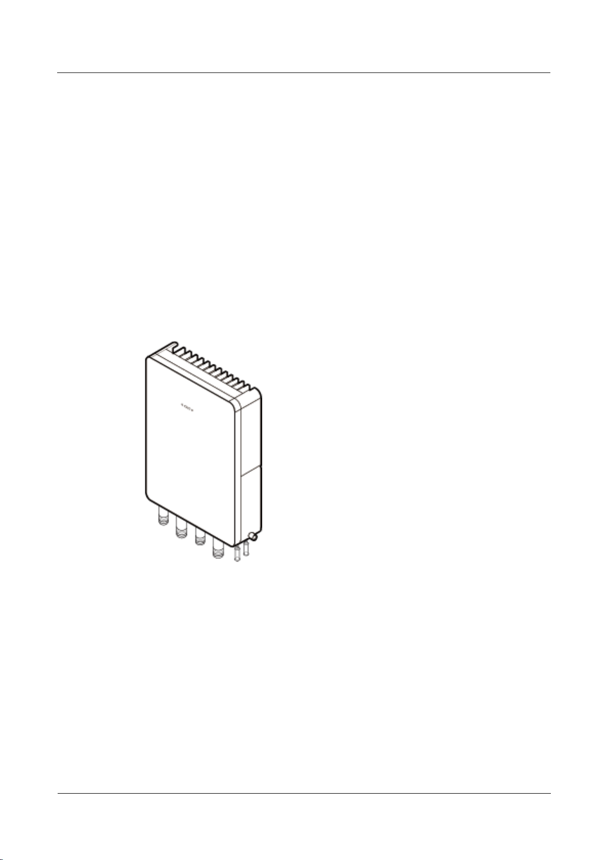
Figure 1-1 shows the exteriors of the eAN3710A.
Figure 1-1 eAN3710A exterior
Figure 1-2 shows the dimensions of eAN3710A.
eAN3710A
Hardware Installation Guide
1 eAN3710A Hardware Description
Issue 01 (2016-12-26)
Huawei Proprietary and Confidential
Copyright © Huawei Technologies Co., Ltd.
3
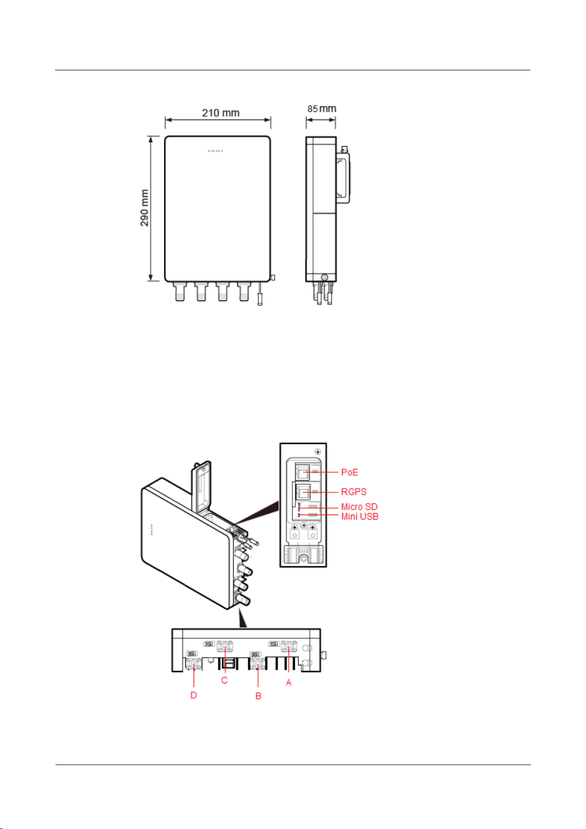
Figure 1-2 eAN3710A dimensions
1.1.2 eAN3710A Ports
This section describes ports on the eAN3710A panels. An eAN3710A has a bottom panel, and
cabling cavity panel.
Figure 1-3 shows the ports on the eAN3710A panels.
Figure 1-3 Ports on the eAN3710A panels
Table 1-1 describes ports on the eAN3710A cabling cavity panels.
eAN3710A
Hardware Installation Guide
1 eAN3710A Hardware Description
Issue 01 (2016-12-26)
Huawei Proprietary and Confidential
Copyright © Huawei Technologies Co., Ltd.
4
Table 1-1 Ports on the eAN3710A cabling cavity panels
Port/Slot
Description
PoE
Used for power supply and data
transmission.
RGPS
Used for clock synchronization.
Micro SD
Used for housing a micro SD card. This slot
is used in the case of deployment.
Mini USB
Used for testing a port.
There are four RF ports on an eAN3710A bottom panel, Table 1-2 lists the TX/RX frequency
band supported by the RF ports.
Table 1-2 TX/RX frequency band supported by the RF ports
RF ports
TX/RX frequency band
A
863 MHz to 870 MHz (Europe)
902 MHz to 928 MHz (Latin America)
B
C
470 MHz to 510 MHz (China)
D
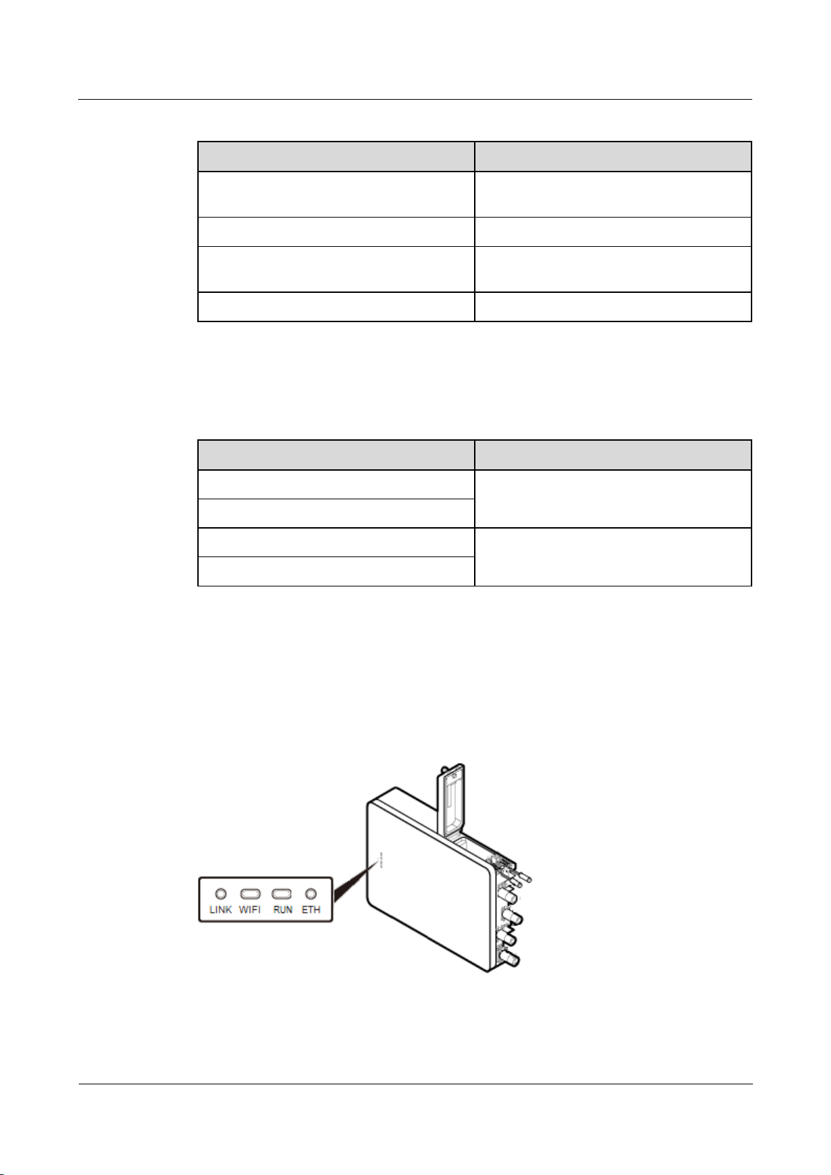
1.1.3 eAN3710A Indicators
This section describes the eAN3710A indicators.
Figure 1-4 shows the position of the eAN3710A indicators.
Figure 1-4 Position of the eAN3710A indicators
Table 1-3 describes the eAN3710A indicators.
eAN3710A
Hardware Installation Guide
1 eAN3710A Hardware Description
Issue 01 (2016-12-26)
Huawei Proprietary and Confidential
Copyright © Huawei Technologies Co., Ltd.
5
Table 1-3 eAN3710A indicators
Indicators
Description
LINK
Link status
WIFI
Wi-Fi processing unit status
RUN
Cellular processing unit status
ETH
ETH status
1.2 Auxiliary Devices
The PSE or Dock supplies power to a eAN3710A through an Ethernet cable in PoE mode.
1.2.1 PSE
This section describes the appearance, dimensions, ports, and indicators of the PSE, and the
PSE specifications.
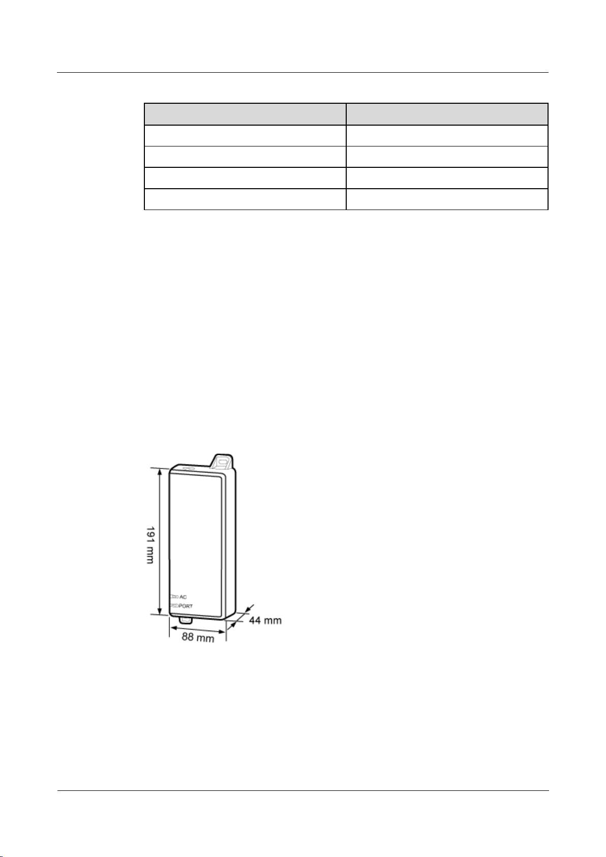
Appearance and Dimensions
Figure 1-5 shows the appearance and dimensions of the PSE.
Figure 1-5 Appearance and dimensions of the PSE
Ports and Indicators
Figure 1-6 shows the ports and indicators on the PSE.
eAN3710A
Hardware Installation Guide
1 eAN3710A Hardware Description
Issue 01 (2016-12-26)
Huawei Proprietary and Confidential
Copyright © Huawei Technologies Co., Ltd.
6
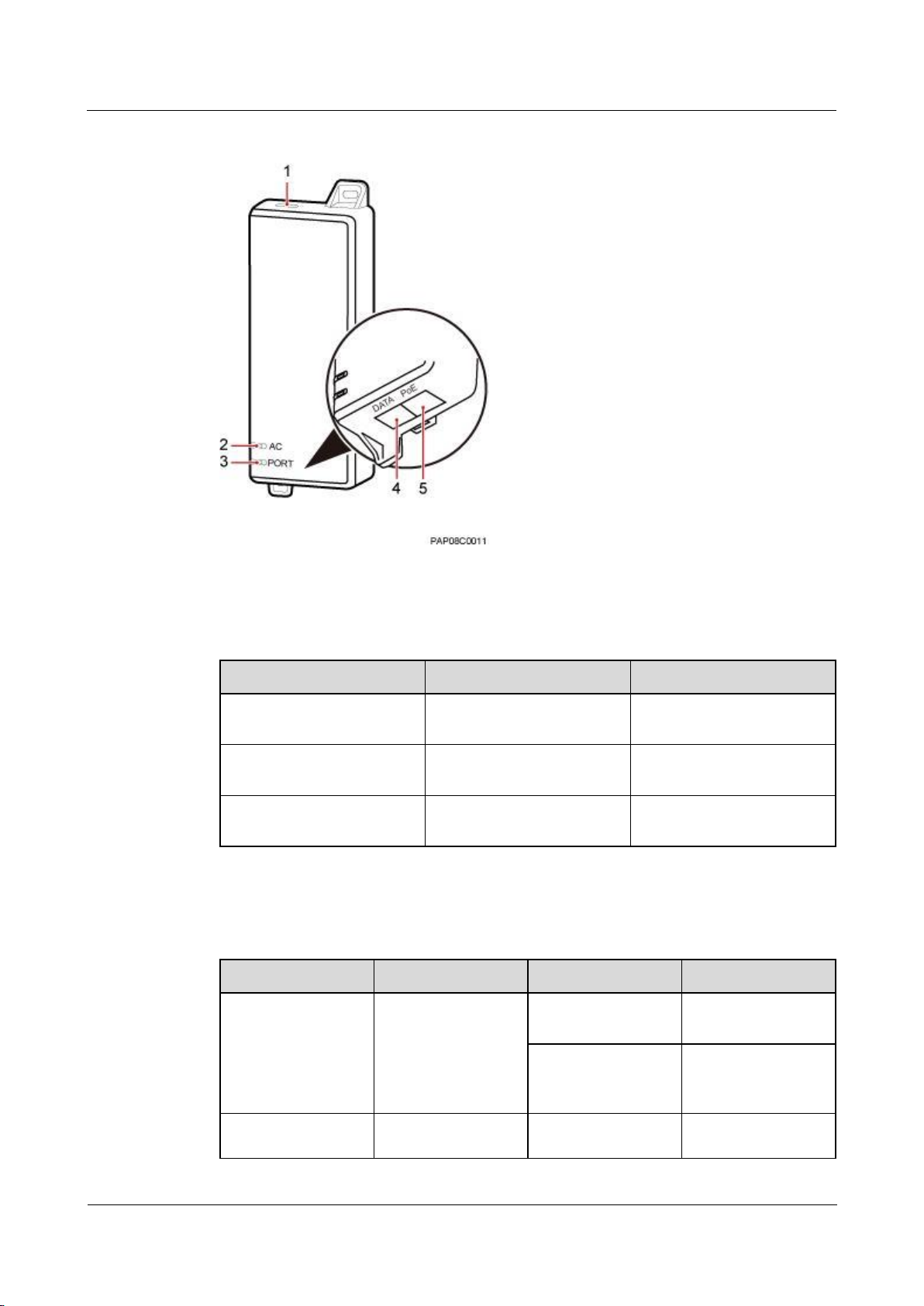
Figure 1-6 PSE ports and indicators
Table 1-4 describes PSE ports.
Table 1-4 PSE ports
No.
Label
Meaning
1
-
Power supply port used for
PSE power supply
4
DATA
Data input port connecting
to a transmission device
5
PoE
PoE output port connecting
to the eAN3710A
Table 1-5 describes PSE indicators.
Table 1-5 PSE indicators
No.
Label
Status
Description
2
AC
Steady green
The power supply is
normal.
Steady off
There is no power
input or the PSE is
faulty.
3
PORT
Steady green
The connection to
the eAN3710A is
eAN3710A
Hardware Installation Guide
1 eAN3710A Hardware Description
Issue 01 (2016-12-26)
Huawei Proprietary and Confidential
Copyright © Huawei Technologies Co., Ltd.
7
No.
Label
Status
Description
normal.
Steady off
The connection to
the eAN3710A is
abnormal or the PSE
is faulty.
Specifications
Table 1-6 lists PSE specifications.
Table 1-6 PSE specifications
Item
Specifications
Input voltage
90 V AC to 264 V AC
Input voltage frequency
47 Hz to 63 Hz
Output voltage
56 V DC
1.2.2 Dock
The Dock supplies power and transfer transmission to a eAN3710A through an Ethernet cable
in PoE mode.
Exterior
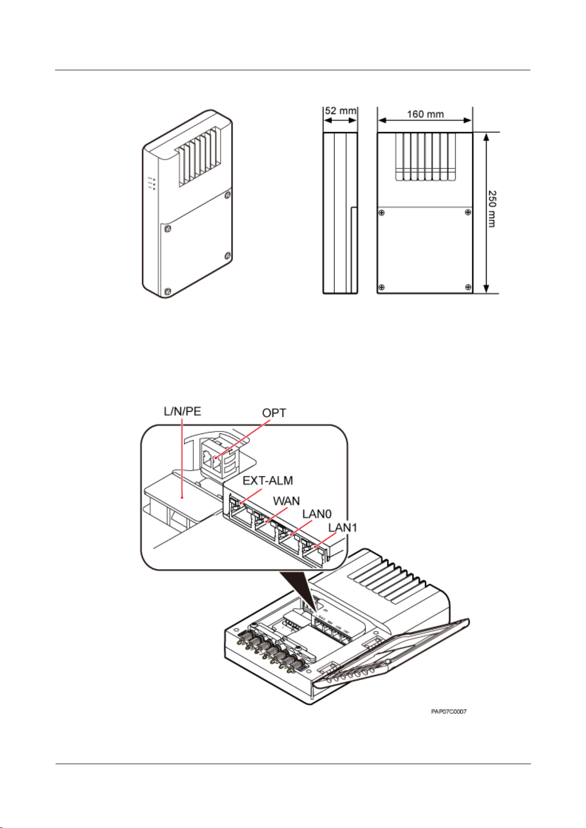
The Dock uses the modular structure. Figure 1-7 shows the exterior and dimensions of a
Dock.
eAN3710A
Hardware Installation Guide
1 eAN3710A Hardware Description
Issue 01 (2016-12-26)
Huawei Proprietary and Confidential
Copyright © Huawei Technologies Co., Ltd.
8
Figure 1-7 Exterior and dimensions of a Dock
Ports
The ports are inside the Dock. Figure 1-8 shows the positions of ports on the Dock.
Figure 1-8 Ports on the Dock
eAN3710A
Hardware Installation Guide
1 eAN3710A Hardware Description
Issue 01 (2016-12-26)
Huawei Proprietary and Confidential
Copyright © Huawei Technologies Co., Ltd.
9
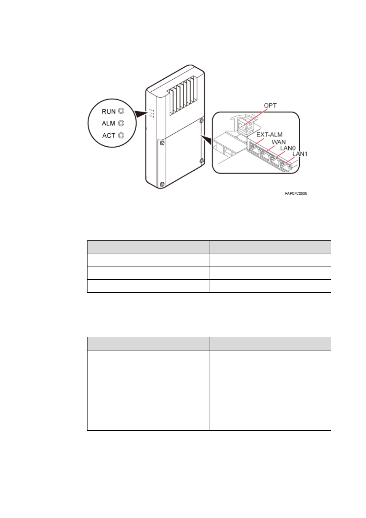
Table 1-7 describes ports on the Dock.
Table 1-7 Meanings of ports on the Dock
Label
Description
OPT
FE/GE optical port, used for connecting an
external transmission devices.
L/N/PE
AC power port, used for connecting an
external power supply device.
EXT-ALM
Environment monitoring port that provides
four dry contacts, used for connecting
external devices and monitoring alarms.
WAN
P&E transmission and power supply port,
used for connecting an external transmission
device.
LAN0
P&E transmission and power supply port,
used for connecting a BTS3205E. A Dock
supplies power to only one eAN3710A.
LAN1
P&E transmission and power supply port.
Used to connect to commissioning devices,
backhaul devices, or cascaded devices.
Indicators
The Dock has three external indicators: RUN, ALM, and ACT. The internal RJ45 connector
has two indicators showing the connection status and data transmission status respectively.
The internal OPT connector has one indicator showing the connection status and data
transmission status. Figure 1-9 shows positions of external indicators on the Dock.
eAN3710A
Hardware Installation Guide
1 eAN3710A Hardware Description
Issue 01 (2016-12-26)
Huawei Proprietary and Confidential
Copyright © Huawei Technologies Co., Ltd.
10
Figure 1-9 Positions of external indicators on the Dock
Table 1-8 describe indicators on the Dock external indicators.
Table 1-8 Dock external indicators
Indicator
Meaning
RUN
Operating status
ALM
Alarm status
ACT
Service status
Table 1-9 describe indicators on the Dock internal indicators.
Table 1-9 Internal indicators on the Dock
Indicator
Meaning
WAN/LAN0/LAN1
Green indicator: connection status
Orange indicator: Data transmission
OPT
Optical status
Steady green: normal connection, no data
transmission.
Fast blinking green (0.125s interval): in the
process of data transmission.
Off: faulty connection.
eAN3710A
Hardware Installation Guide
1 eAN3710A Hardware Description
Issue 01 (2016-12-26)
Huawei Proprietary and Confidential
Copyright © Huawei Technologies Co., Ltd.
11
1.3 Mounting Kits
This section describes the mounting brackets for installing a eAN3710A.
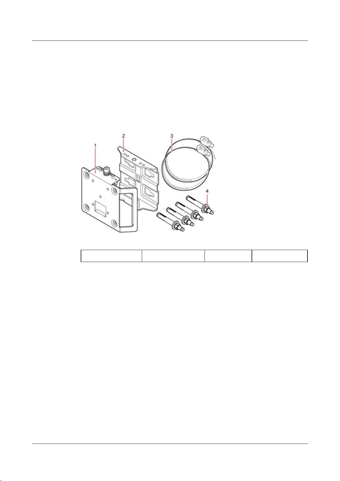
1.3.1 eAN3710A Mounting Kits
This section describes mounting kits and attachment plates for installing eAN3710A.
Figure 1-10 shows a mounting bracket and a attachment plate.
Figure 1-10 Mounting bracket and common attachment plate for eAN3710A
(1) Attachment plate
(2) Mounting bracket
(3) Hose clamp
(4) Expansion bolt
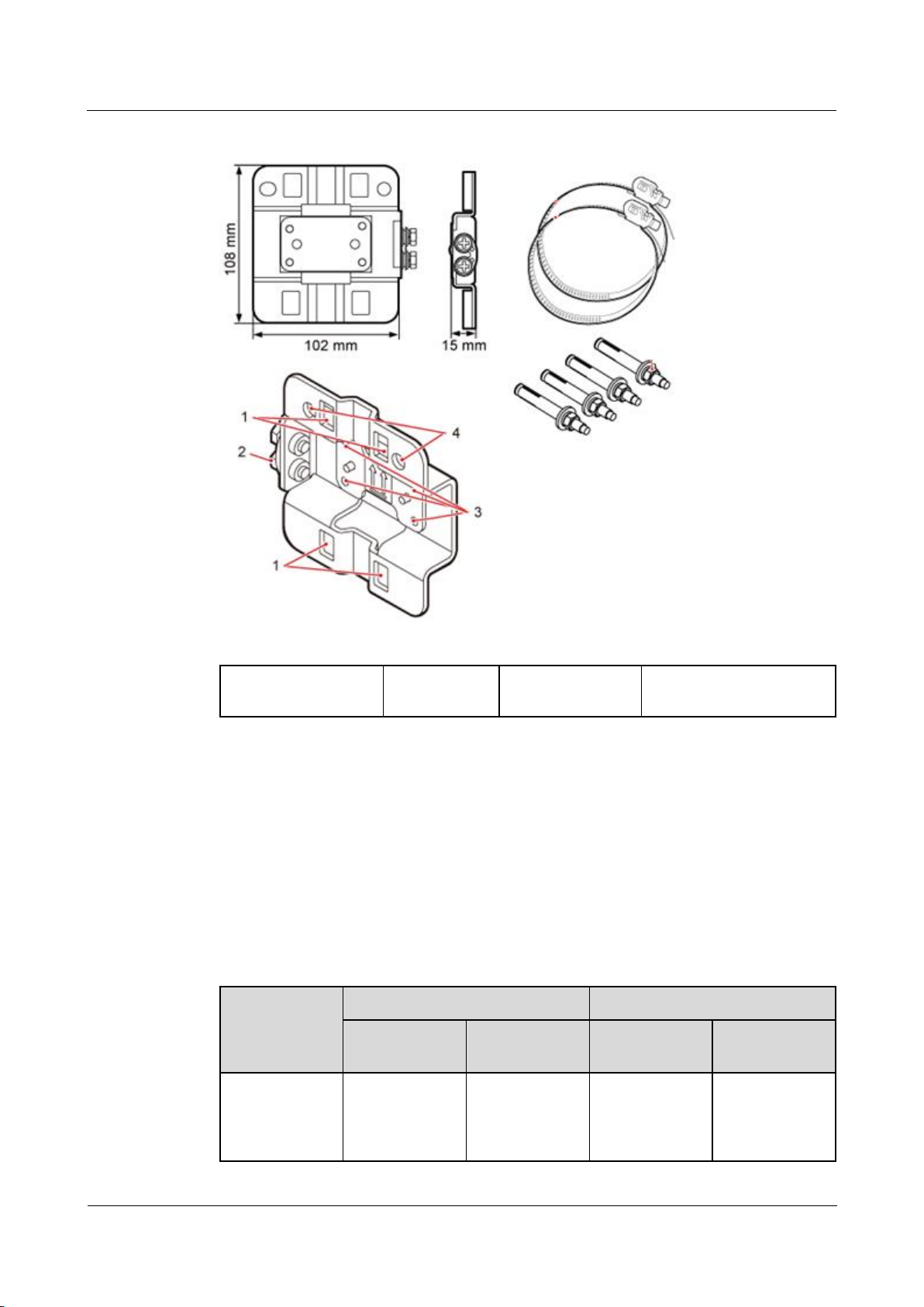
1.3.2 Dock Mounting Kits
This section describes the mounting brackets for installing a Dock.
Figure 1-11 shows a separate Dock mounting bracket.
eAN3710A
Hardware Installation Guide
1 eAN3710A Hardware Description
Issue 01 (2016-12-26)
Huawei Proprietary and Confidential
Copyright © Huawei Technologies Co., Ltd.
12
Figure 1-11 Appearance of a separate Dock mounting bracket
(1) Hole for routing a
hose clamp
(2) Ground
terminal
(3) Hole for a
captive screw
(4) Hole for inserting an
expansion bolt
1.4 Cables
This section describes eAN3710A cables.
1.4.1 Cable List
This section describes eAN3710A cable connections.
Table 1-10 lists eAN3710A cables.
Table 1-10 List of eAN3710A cables
Cable
One End
The Other End
Connector
Connected
to ...
Connector
Connected
to ...
1.4.2 Ethernet
Cable
RJ45 connector
eAN3710A/Po
E port
RJ45 connector
If connected to
PSE/DATA
port
If connected to
eAN3710A
Hardware Installation Guide
1 eAN3710A Hardware Description
Issue 01 (2016-12-26)
Huawei Proprietary and Confidential
Copyright © Huawei Technologies Co., Ltd.
13
Cable
One End
The Other End
Connector
Connected
to ...
Connector
Connected
to ...
Dock/LAN0
port
1.4.3 PGND
cable
OT terminal
(M6)
Ground
terminal on the
eAN3710A
OT terminal
(M8)
Ground
terminal on the
ground bar
OT terminal
(M6)
Ground
terminal on the
Dock
OT terminal
(M8)
Ground
terminal on the
ground bar
1.4.4 RF
Jumper
Type N male
connector
External
antenna TX/RX
RF port on
eAN3710A
Based on the
port model of
the antenna
system.
Antenna system
1.4.5 RGPS
Signal Cable
RJ45 connector
eAN3710A/RG
PS port
Round 12-pin
connector
RGPS device
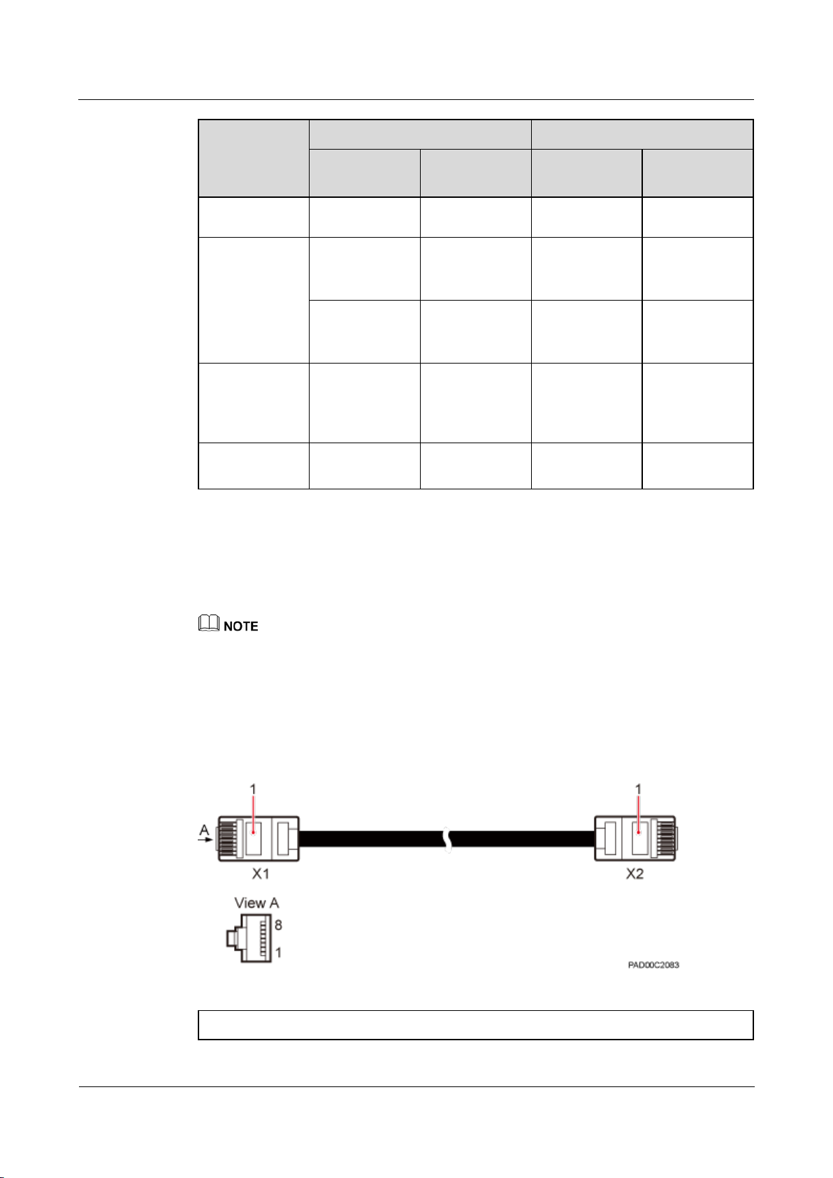
1.4.2 Ethernet Cable
This section describes the appearance, pin assignment, and installation position for an
Ethernet cable connecting an auxiliary devices and a eAN3710A.
The Ethernet cable must be of Category 5e (enhanced) or higher. In addition, its cross-sectional area
must be 24 AWG or larger and frame spread rating must be CM or higher.
With the internal PoE module providing power, the maximum length of an Ethernet cable is 100 m.
Both the cable and the RJ45 connectors are delivered, and they must be assembled onsite.
Both ends of the Ethernet cable are RJ45 connector, as shown in Figure 1-12.
Figure 1-12 Ethernet cable exterior
(1) RJ45 connector
eAN3710A
Hardware Installation Guide
1 eAN3710A Hardware Description
Issue 01 (2016-12-26)
Huawei Proprietary and Confidential
Copyright © Huawei Technologies Co., Ltd.
14
Table 1-11 shows the pin assignment for wires of the Ethernet cable.
Table 1-11 Pin assignment for wires of the Ethernet cable
Pin of the RJ45
Connector
Color
Core Wire
Pin of the RJ45 Connector
X1.2
Orange
Twisted pair
cable
X2.2
X1.1
White/Orange
X2.1
X1.6
Green
Twisted pair
cable
X2.6
X1.3
White/green
X2.3
X1.4
Blue
Twisted pair
cable
X2.4
X1.5
White/Blue
X2.5
X1.8
Brown
Twisted pair
cable
X2.8
X1.7
White/brown
X2.7
1.4.3 PGND cable
An eAN3710A PGND cable connects an eAN3710A and a ground bar, Dock and a ground bar
ensuring the proper grounding of the eAN3710A and Dock. The maximum length of an
eAN3710A PGND cable is 8 m (26.25 ft).
Exterior
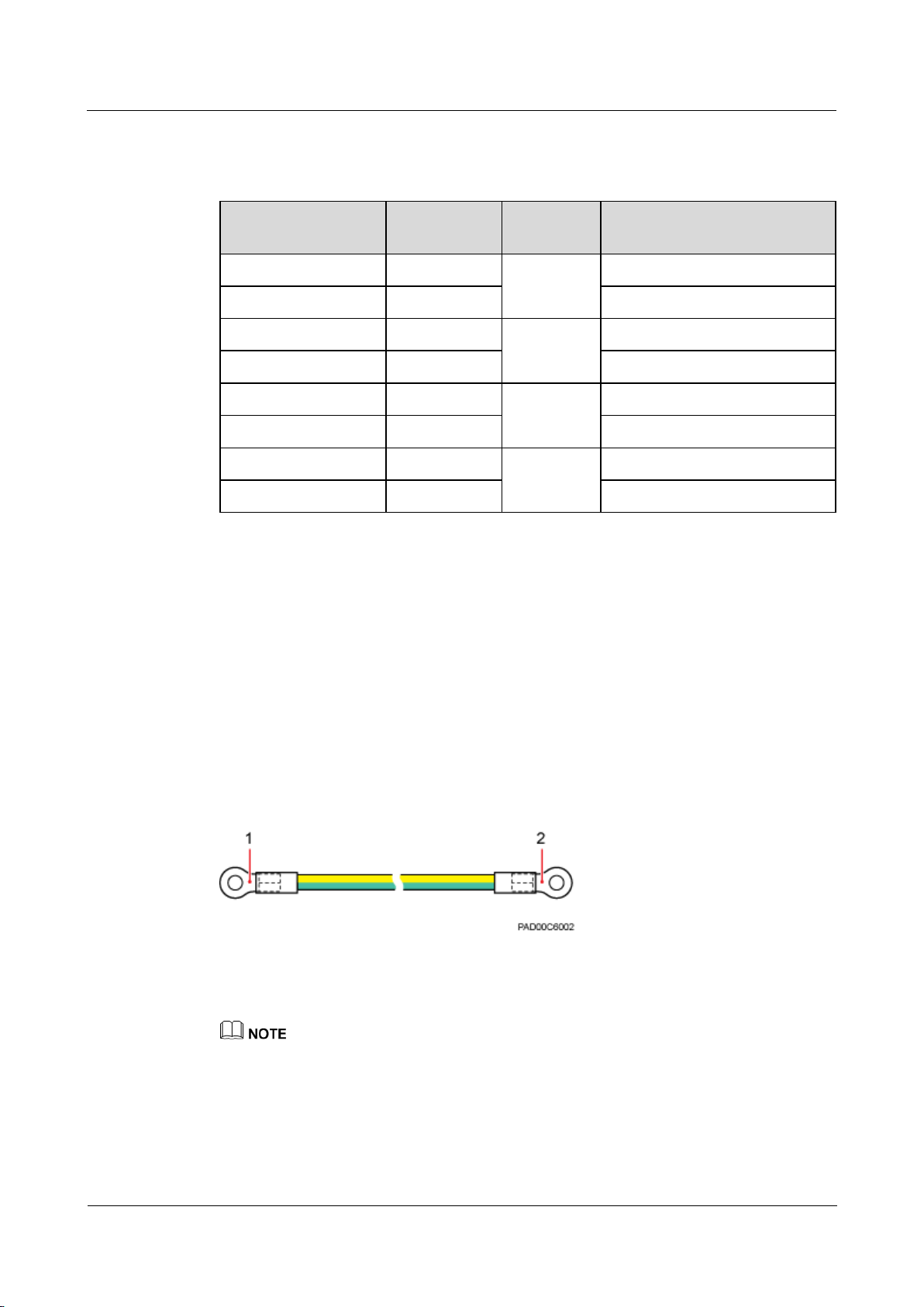
The yellow and green or green PGND cable is a single cable. The cross-sectional area of the
PGND cable is 6 mm2 (0.009 in.2). Both ends of the cable are OT terminals, as shown in
Figure 1-13.
Figure 1-13 Exterior of a PGND cable
(1) OT terminal (M6)
(2) OT terminal (M8)
If the PGND cable is provided by the customer, a copper-core cable with a minimum cross-sectional
area of 6 mm2 (0.009 in.2) or 10 AWG is recommended.
The OT terminals at both ends of the PGND cable are assembled at the site.
The M6 OT terminal has the default size. You can replace it with another OT terminal of the
expected size based on the site requirement.
eAN3710A
Hardware Installation Guide
1 eAN3710A Hardware Description
Issue 01 (2016-12-26)
Huawei Proprietary and Confidential
Copyright © Huawei Technologies Co., Ltd.
15
Installation Position
The M6 OT terminal of the PGND cable is connected to the ground screw on the eAN3710A
and Dock, and the M8 OT terminal of the PGND cable is connected to the ground bar at the
site.
1.4.4 RF Jumper
The eAN3710A RF jumper transmits and receives RF signals.
If the customer prepares the RF jumper, the length of the RF jumper should be as short as possible and
not exceed 2 m (6.56 ft.).
Both end of the outdoor RF jumper is the type N male connector. Figure 1-14 shows the RF
jumper.
Figure 1-14 RF jumper
(1) Type N male connector
1.4.5 RGPS Signal Cable
The RGPS signal cable between the eAN3710A and RGPS device is used for clock
synchronization. This cable is optional for the eAN3710A.
If the customer uses their own radio frequency (RF) jumpers, it is recommended that the length of RF
jumpers be 2 m.
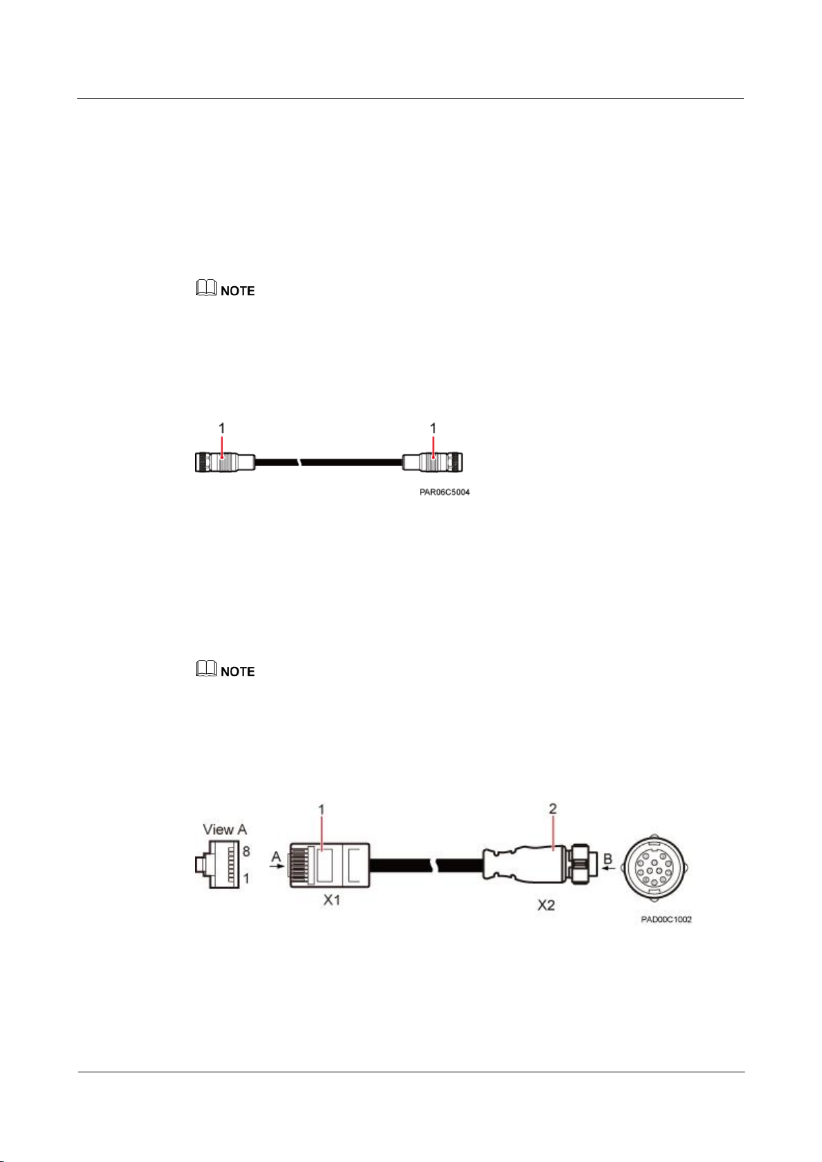
An RGPS signal cable has an RJ45 connector at one end and a round 12-pin connector at the
other end, as shown in Figure 1-15.
Figure 1-15 Appearance of an RGPS signal cable
(1) RJ45 connector
(2) Round 12-pin connector
eAN3710A
Hardware Installation Guide
2 eAN3710A Hardware Installation Guide
Issue 01 (2016-12-26)
Huawei Proprietary and Confidential
Copyright © Huawei Technologies Co., Ltd.
16
2 eAN3710A Hardware Installation Guide
About This Chapter
Overview
This document describes the process of installing eAN3710A.
Product Version
Unless otherwise stated, "eNodeB", "Pico", "eAN", and "AirNode" in this document refer to the 3710
series AirNode.
The 3710 series AirNode is a base station that provides communications services in Huawei
eLTE-IoT solution. The following table lists the product name and product version related to
the 3710 series AirNode.
Product Name
Product Version
eAN3710A
V100R001C00
Intended Audience
This document is intended for installation engineers.
Organization
2.1 Installation Preparations
Before starting the installation, you must obtain the required reference documents, tools, and
instruments, and familiarize yourself with the skills required.
2.2 Information About the Installation
This section describes the information that you must be familiar with before installing a
eAN3710A, including the eAN3710A hardward infomation, installation scenarios, installation
space and environment requirements.
2.3 Unpacking the Equipment

eAN3710A
Hardware Installation Guide
2 eAN3710A Hardware Installation Guide
Issue 01 (2016-12-26)
Huawei Proprietary and Confidential
Copyright © Huawei Technologies Co., Ltd.
17
This section describes how to unpack and check the delivered equipment to ensure that all the
materials are included and intact.
2.4 Installation Process
This section describes the eAN3710A installation process.
2.5 Obtaining the ESN
Before installing the eAN3710A, record its electronic serial number (ESN) for future use
during commissioning.
2.6 (Optional) Installing a Micro SD Card
This section describes how to install a micro SD card in the eAN3710A.
2.7 Installing the eAN3710A
This section describes the eAN3710A installation process.
2.8 Installing the Auxiliary Devices
This section describes the procedure and precautions for installing the auxiliary devices.
2.9 Installing eAN3710A Cables
This section describes the procedures for installing eAN3710A cables and auxiliary devices
cables.
2.10 Checking the eAN3710A Hardware Installation
eAN3710A hardware installation checking includes hardware and cable installation checking.
2.11 Power-On Check on the eAN3710A
This section describes the procedure for performing a power-on check on the eAN3710A.
2.12 Appendix
This section describes reference information during installation.
2.1 Installation Preparations
Before starting the installation, you must obtain the required reference documents, tools, and
instruments, and familiarize yourself with the skills required.
2.1.1 Reference Documents
Before the installation, you must be familiar with reference documents.
The following reference documents are required during eAN3710A installation:
Health and Safety
Equipment Safety
1 eAN3710A Hardware Description
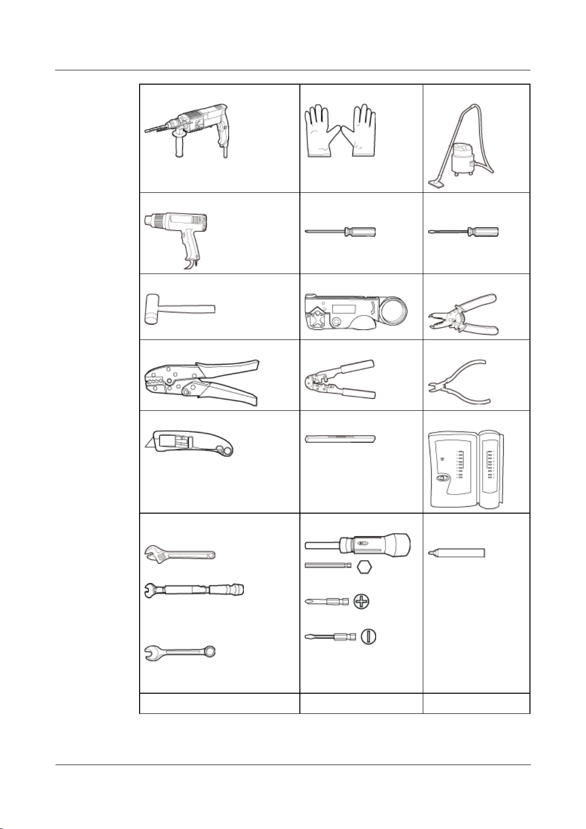
2.1.2 Tools and Instruments
You must prepare the following tools and instruments before the installation.
eAN3710A
Hardware Installation Guide
2 eAN3710A Hardware Installation Guide
Issue 01 (2016-12-26)
Huawei Proprietary and Confidential
Copyright © Huawei Technologies Co., Ltd.
18
Hammer drill (a φ12 bit)
ESD gloves
Vacuum cleaner
Heat gun
Phillips screwdriver (M3
to M6)
Flat-head screwdriver
(M3 to M6)
Rubber mallet
COAX crimping tool
Wire stripper
Power cable crimping tool
RJ45 crimping tool
Diagonal plier
Utility knife
Level
Network cable tester
Adjustable wrench (size ≥ 32 mm
[1.26 in.])
Torque wrench
Size: 16 mm (0.63 in.) and 22 mm
(0.87 in.)
Combination wrench
Size: 16 mm (0.63 in.) and 22 mm
(0.87 in.)
Torque screwdriver
3mm or 5mm
(M3 to M6)
(M3 to M6)
Marker (diameter ≤ 10
mm [0.39 in.])
Torque socket (M6 or M10)
Multimeter
Measuring tape
 Loading...