

eA680-950 LTE DAU
User Guide
Issue
01
Date
2017-03-03
HUAWEI TECHNOLOGIES CO., LTD.

Issue 01 (2017-03-03)
Huawei Proprietary and Confidential
Copyright © Huawei Technologies Co., Ltd.
i
Copyright © Huawei Technologies Co., Ltd. 2016. All rights reserved.
No part of this document may be reproduced or transmitted in any form or by any means without prior
written consent of Huawei Technologies Co., Ltd.
Trademarks and Permissions
and other Huawei trademarks are trademarks of Huawei Technologies Co., Ltd.
All other trademarks and trade names mentioned in this document are the property of their respective
holders.
Notice
The purchased products, services and features are stipulated by the contract made between Huawei and
the customer. All or part of the products, services and features described in this document may not be
within the purchase scope or the usage scope. Unless otherwise specified in the contract, all statements,
information, and recommendations in this document are provided "AS IS" without warranties, guarantees or
representations of any kind, either express or implied.
The information in this document is subject to change without notice. Every effort has been made in the
preparation of this document to ensure accuracy of the contents, but all statements, information, and
recommendations in this document do not constitute a warranty of any kind, express or implied.
Huawei Technologies Co., Ltd.
Address:
Huawei Industrial Base
Bantian, Longgang
Shenzhen 518129
People's Republic of China
Website:
http://www.huawei.com
Email:
support@huawei.com
eA680-950 LTE DAU
User Guide
About This Document
Issue 01 (2017-03-03)
Huawei Proprietary and Confidential
Copyright © Huawei Technologies Co., Ltd.
ii
Overview
Product Name
Product Version
eA680-950
V100R001C00
This document describes the hardware, functions, installation, configuration, operation and
maintenance (OM) of the eA680-950 customer premises equipment (DAU).
Product Version
About This Document
Intended Audience
This document is intended for:
System engineers
Product engineers
Technical support engineers

eA680-950 LTE DAU
User Guide
Contents
Issue 01 (2017-03-03)
Huawei Proprietary and Confidential
Copyright © Huawei Technologies Co., Ltd.
iii
Contents
About This Document ............................................................................................................ ii
1 Overview ................................................................................................................................ 1
1.1 Product Introduction ............................................................................................................................................................. 1
1.2 Application Scenarios ........................................................................................................................................................... 1
1.3 Hardware Specifications....................................................................................................................................................... 4
1.4 Antenna Specifications ......................................................................................................................................................... 5
1.5 Software................................................................................................................................................................................. 6
1.6 Product Security .................................................................................................................................................................... 7
1.6.1 Network Security ............................................................................................................................................................... 7
1.6.2 Application Security .......................................................................................................................................................... 8
1.7 Device Ports ........................................................................................................................................................................ 10
1.7.1 Web Port ........................................................................................................................................................................... 10
1.7.2 USB Port .......................................................................................................................................................................... 11
1.7.3 TR-069 Port ...................................................................................................................................................................... 12
2 Hardware .............................................................................................................................. 14
2.1 eA680-950 Hardware ......................................................................................................................................................... 14
2.2 eA680-950Cables................................................................................................................................................................ 17
2.2.1 PoE Network Cable ......................................................................................................................................................... 17
2.2.2 Ground Cable ................................................................................................................................................................... 18
3 Installation ........................................................................................................................... 19
3.1 Site Preparations ................................................................................................................................................................. 19
3.2 Installation Preparation ....................................................................................................................................................... 20
3.3 Installation Procedure ......................................................................................................................................................... 22
3.3.1 Mounting on a Utility Pole.............................................................................................................................................. 22
3.3.2 Mounting on the Wall ...................................................................................................................................................... 26
3.3.3 Cable Connection............................................................................................................................................................. 32
3.4 Installation Check ............................................................................................................................................................... 35
4 Configuration Introduction ................................................................................................ 38
4.1 Log in to the WebUI ........................................................................................................................................................... 38
5 Maintenance ......................................................................................................................... 39
5.1 Maintenance Preparation .................................................................................................................................................... 39

eA680-950 LTE DAU
User Guide
Contents
Issue 01 (2017-03-03)
Huawei Proprietary and Confidential
Copyright © Huawei Technologies Co., Ltd.
iv
5.2 Fault Diagnosis ................................................................................................................................................................... 39
6 FAQ ....................................................................................................................................... 41
6.1 What Do I Do If the Web UI Fails to Be Opened? ........................................................................................................... 41
6.2 What Do I Do When Power Indicator Is Not Working? ................................................................................................... 41
6.3 What Do I Do When the Data Service Is not Provided? .................................................................................................. 42
7 Privacy and Security ............................................................................................................ 43
7.1 Privacy Policy ..................................................................................................................................................................... 43
7.2 Security Maintenance ......................................................................................................................................................... 43
7.3 Performing Default Security Configuration ...................................................................................................................... 43
8 FCC warning ........................................................................................................................ 45
This equipment has been tested and found to comply with the limits for a Class B digital device, pursuant to part 15 of
the FCC Rules. These limits are designed to provide reasonable protection against harmful interference in a residential
installation. This equipment generates, uses and can radiate radio frequency energy and, if not installed and used in
accordance with the instructions, may cause harmful interference to radio communications. However, there is no
guarantee that interference will not occur in a particular installation. If this equipment does cause harmful interference
to radio or television reception, which can be determined by turning the equipment off and on, the user is encouraged to
try to correct the interference by one or more of the following measures: ........................................................................... 45
9 Acronyms and Abbreviations............................................................................................. 46

eA680-950 LTE DAU
User Guide
1 Overview
Issue 01 (2017-03-03)
Huawei Proprietary and Confidential
Copyright © Huawei Technologies Co., Ltd.
1
About This Chapter
This section describes the functions, applications, and specifications of the product.
1.1 Product Introduction
1 Overview
The Huawei eA680-950 V1R1 outdoor DAU are the Long Term Evolution (LTE) customer
premises equipment (DAU). As a wireless gateway, it can be deployed outdoors to provide
services such as data collection and video surveillance.
The eA680-950 provides the following functions:
Data service
Wi-Fi Service
Security service
Local and remote maintenance and management
Data routing.
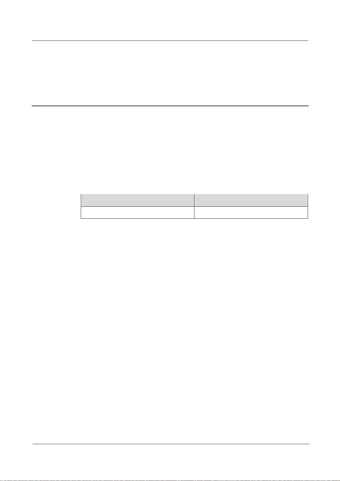
1.2 Application Scenarios
The eA680-950 is specially designed for outdoor deployment to obtain better wireless access
performance to the LTE network.
The eA680-950 can be deployed in wISP, industrial, public security and enterprise network if
the performance is acceptable to the network operator.
eA680-950 LTE DAU
User Guide
1 Overview
Issue 01 (2017-03-03)
Huawei Proprietary and Confidential
Copyright © Huawei Technologies Co., Ltd.
2
Figure 1-1 The eA680-950 deployed in wISP network
Figure 1-2 The eA680-950 deployed in industrial network
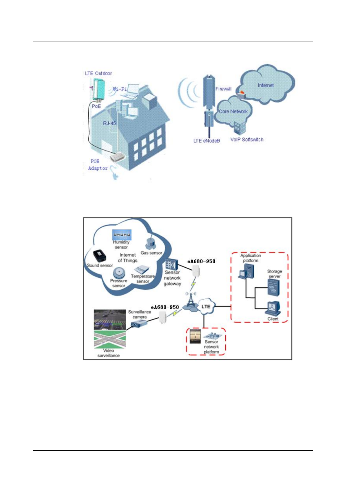
The following example describes how to use the eA680-950 for video monitoring.
1. Use a power adapter to supply power for the eA680-950 or video camera, as shown in
Figure 1-3.
eA680-950 LTE DAU
User Guide
1 Overview
Issue 01 (2017-03-03)
Huawei Proprietary and Confidential
Copyright © Huawei Technologies Co., Ltd.
3
Figure 1-3 The eA680-950 connected to a video camera.
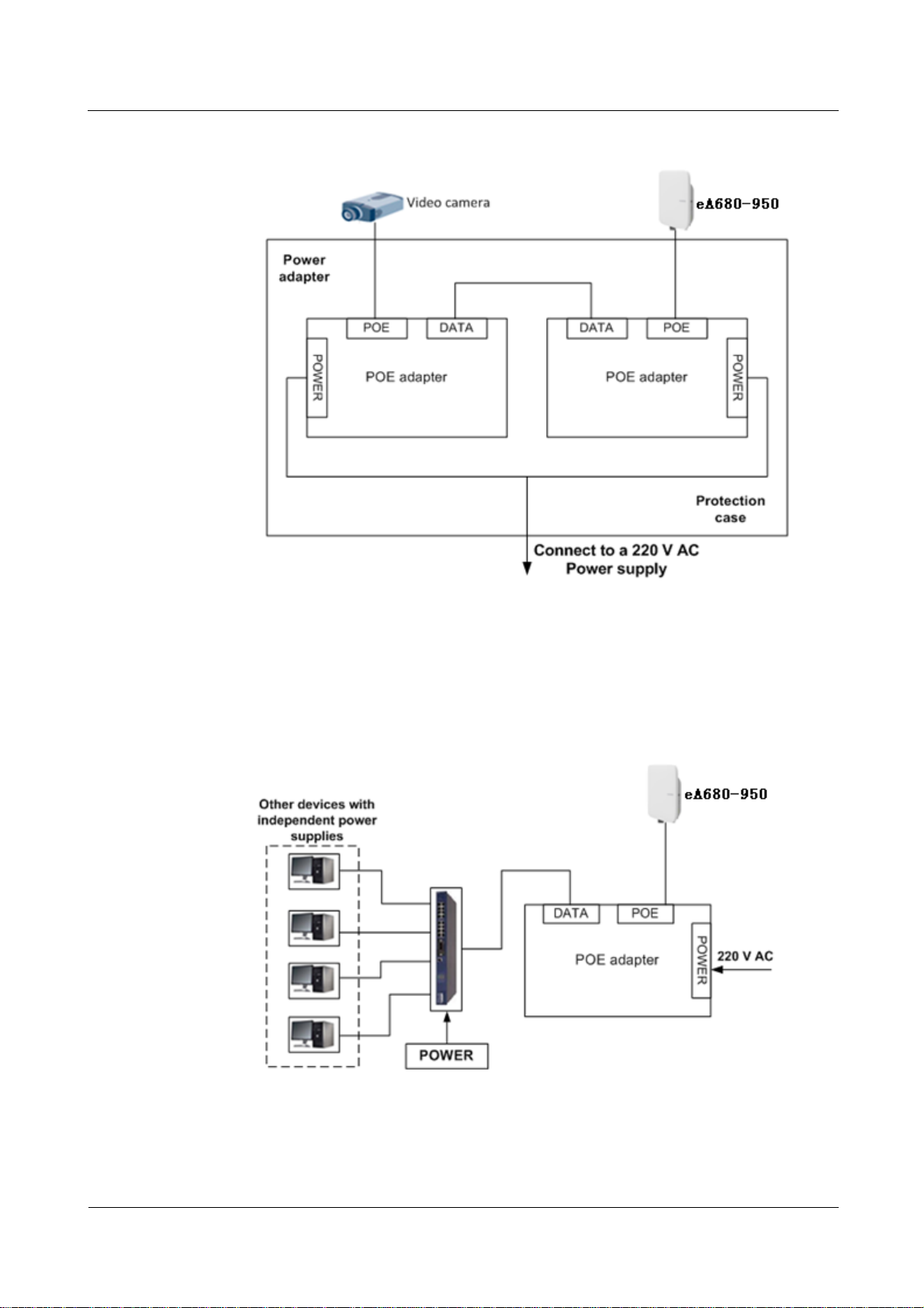
2. Use a network cable to connect the eA680-950 to an external device. If the eA680-950
connects to a single device, connect the power adapter directly to the eA680-950. If the
eA680-950 connects to multiple devices, connect the power adapter to a Hub or switch
and then to the eA680-950, as shown in Figure 1-4.
Figure 1-4 The eA680-950 connected to multiple devices
eA680-950 LTE DAU
User Guide
1 Overview
Issue 01 (2017-03-03)
Huawei Proprietary and Confidential
Copyright © Huawei Technologies Co., Ltd.
4
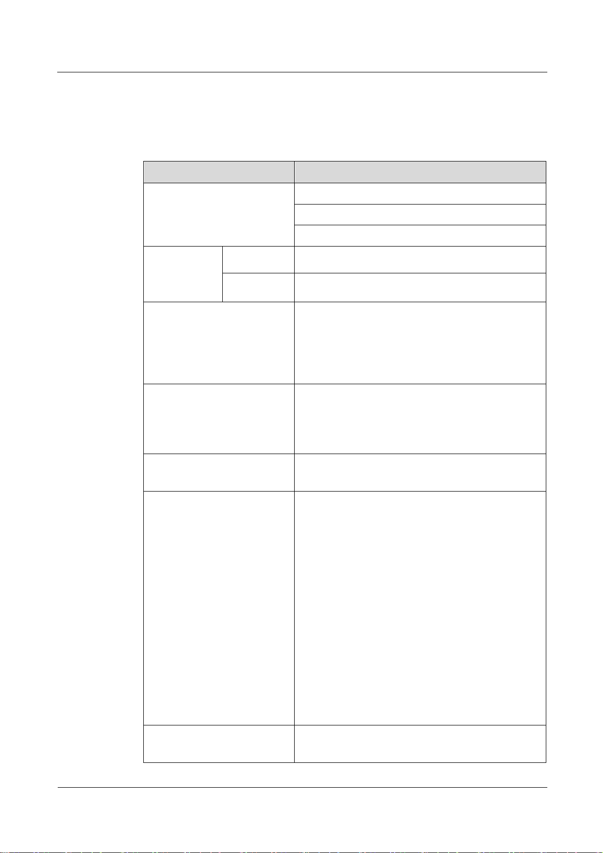
1.3 Hardware Specifications
Category
Description
Technical standard
WAN: LTE 3GPP Release 11
LAN: IEEE 802.3/802.3u
WLAN: IEEE 802.11b/g/n
Working
frequency band
LTE
LTE TDD 5.8G: 5725 MHz to 5850 MHz
WLAN
2400MHz to 2483.5MHz
External interface
1 Ethernet interface (RJ45): 10/100Base-TX
1 USB interface
2 External antenna interface (N type Female
connector)
1 SIM card slot
LED indicator
One POWER indicator
One CONNECT indicator
One RSSI indicator
One HEAT indicator
Maximum transmit power
LTE: 23 dBm (±2)
WLAN: 16dBm(±2 dB)
Receiving sensitivity
LTE:
< -96 dBm/5 MHz
< -93 dBm/10 MHz
< -90 dBm/20 MHz
WLAN:
802.11b: -92 dBm@1 Mbps,
-85 dBm@11 Mbps
802.11g: -88 dBm@6 Mbps
-73 dBm@54 Mbps
802.11n:
HT20:-87 dBm@MCS0
-71 dBm@MCS7
HT40:-84 dBm@MCS0
-68 dBm@MCS7
Power consumption
<25W when heater works
<12W when heater off
Table 1-1 describes the technical specifications of eA680-950.
Table 1-1 Hardware specifications of eA680-950
eA680-950 LTE DAU
User Guide
1 Overview
Issue 01 (2017-03-03)
Huawei Proprietary and Confidential
Copyright © Huawei Technologies Co., Ltd.
5
Category
Description
Power supply
POE comply with IEEE802.3at
Dimensions (W×D×H)
285 mm x 250 mm x 85 mm;
Weight
About 3kg (The power supply adapter is not included)
Water and dust proof
IP65
Temperature
Working temperature: -40℃~ +55℃
Storage temperature: -40℃ ~ +70℃
Humidity
5% ~ 95%
Installation
Mounted on poles or walls
Utility pole diameter
60 mm to 114 mm
Item
eA680-950
Band
5725 to 5850 MHz
Gain
11±1 dBi
Input
impedance
50 ohm
SWR
< 2
Polarization
Dual polarization
Radiation
pattern
Directional antenna
Tip: Within three months after the arrival,it is recommended to use the equipment, or store in
the following environment:
Temperature: -10 ℃ to 35 ℃
Relative humidity (RH): 30% RH to 85% RH
Storage environment should be equipped with temperature and humidity equipments and
dehumidification equipment to monitor and adjust the temperature and humidity.
1.4 Antenna Specifications
Table 1-2 and lists the eA680-950 antenna's specifications.
Table 1-2 eA680-950 LTE antenna specifications
eA680-950 LTE DAU
User Guide
1 Overview
Issue 01 (2017-03-03)
Huawei Proprietary and Confidential
Copyright © Huawei Technologies Co., Ltd.
6
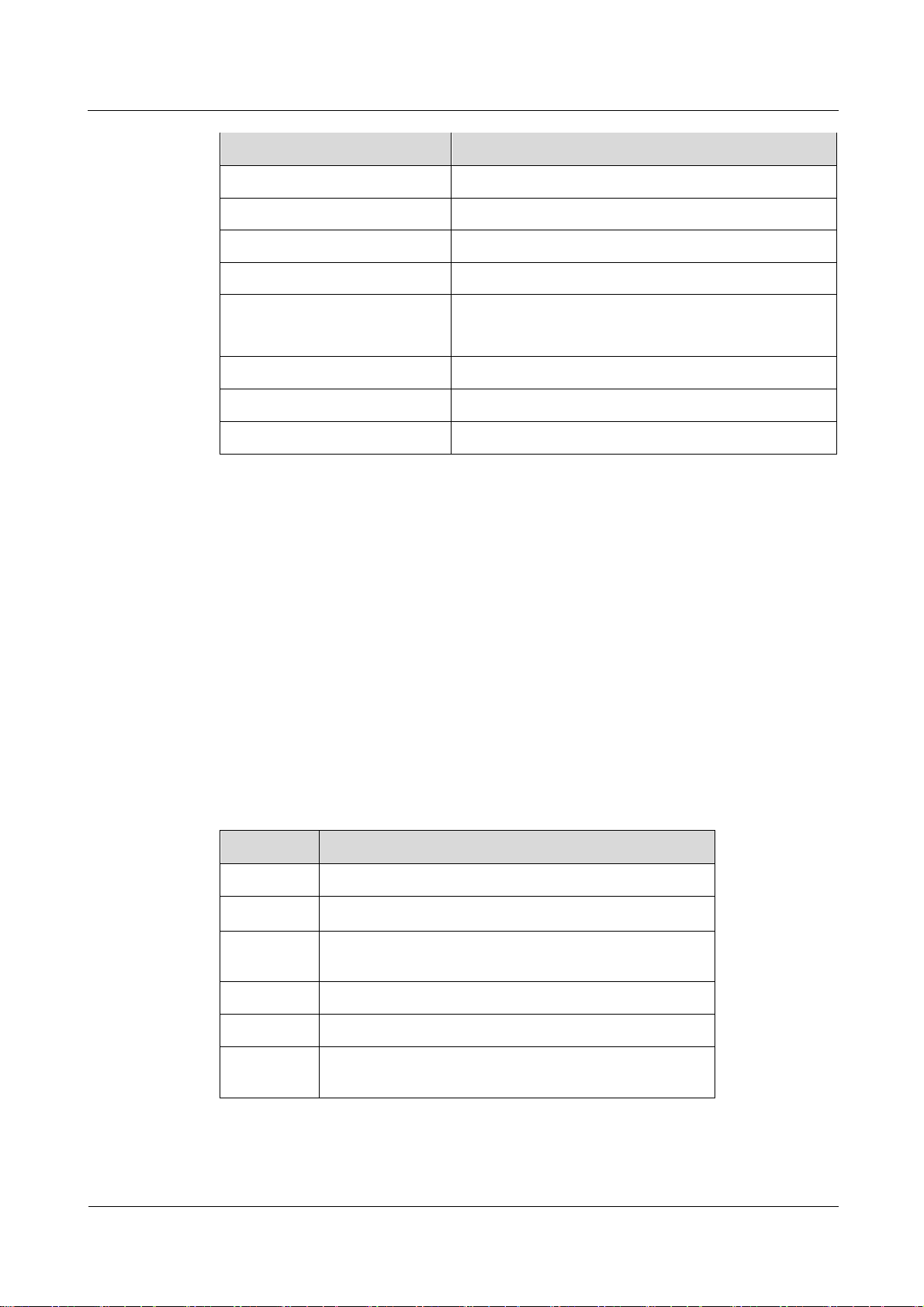
Table 1-3 WLAN antenna specifications
Item
Description
Frequency
2.4 GHz ~ 2.483 GHz
Input impedance
50 Ω
Standing wave ratio
< 3
efficiency
≥50%
Gain
≥2dBi
Polarization
Linear polarization
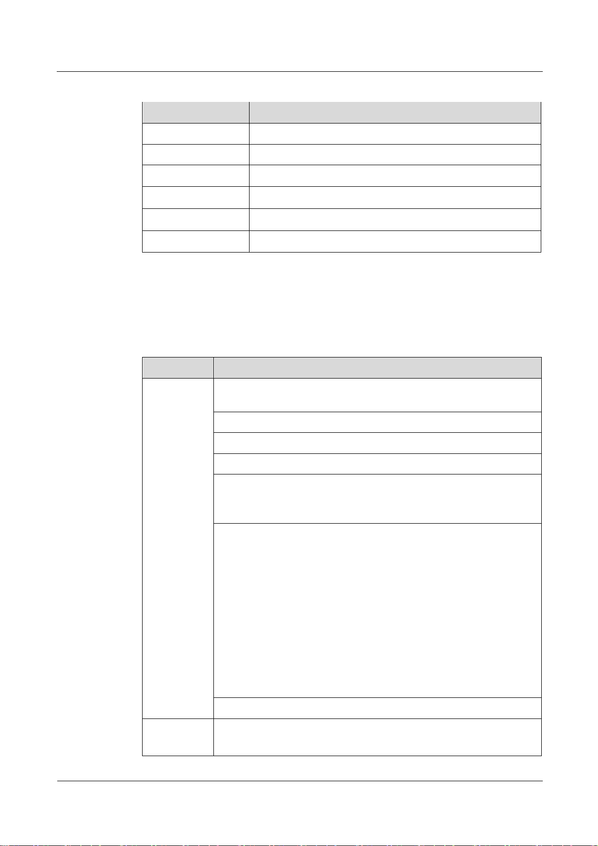
Item
Description
Gateway
Router: The default routing address is 0.0.0.0. The default routing table
items can be generated accordingly.
Supports Address Resolution Protocol (ARP)
Supports domain name service (DNS)
Supports Internet Control Message Protocol (ICMP)
NAT
Supports Network Address Translation (NAT) and Network Address
Port Translation (NAPT).
DHCP server
The default DHCP server address ranges from 192.168.1.2 to
192.168.1.254. The default gateway address is 192.168.1.1.
The default DHCP lease is 24 hours.
The DHCP server can be enabled or disabled.
The DHCP server's address pool can be configured.
The DHCP lease can be configured.
IP address status such as the hostname, Media Access Control (MAC)
address, IP address, and remaining DHCP lease can be displayed.
Supports static IP address reservation
Support DHCP relay.
Routing behind MS
Firewall
Firewall switch
LAN MAC address filtering
1.5 Software
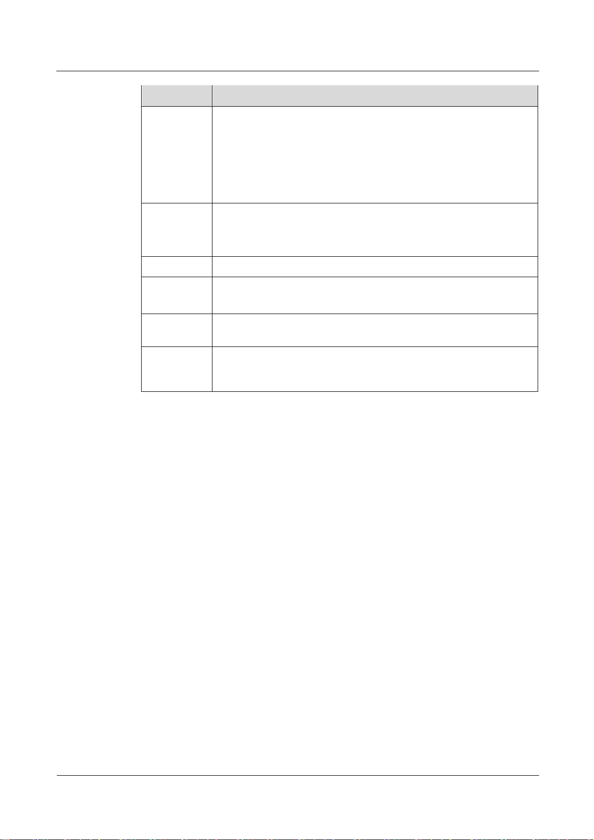
Table 1-4 Software specifications
eA680-950 LTE DAU
User Guide
1 Overview
Issue 01 (2017-03-03)
Huawei Proprietary and Confidential
Copyright © Huawei Technologies Co., Ltd.
7
Item
Description
IP address filtering
URL filtering
Security Parameter Index (SPI) filtering
Demilitarized Zone (DMZ)
Port forwarding
Service access control
LAN
Auto-negotiation between 10 Mbit/s /100 Mbit/s/1000 Mbit/s
MDI/MDIX auto-sensing
Compatible with IEEE 802.3/802.3u
Upgrade
Supports TR-069 upgrade and local upgrade.
SIM
Supports PIN management and SIM card authentication
soft SIM
Dial-up
connection
Supports automatic and manual connection
Importing and
exporting
configuration
Encrypt and back up the current configuration, and then restore from a
backup configuration
1.6 Product Security
eA680-950 security includes network security and application security. Application security
includes wireless security and OM security.
1.6.1 Network Security
eA680-950 network security uses Secure Sockets Layer (SSL) and Hypertext Transfer
Protocol Secure (HTTPS).
SSL
The SSL protocol is a security connection technology for the server and client. It provides a
confidential, trusted, and identity-authenticating connection to two application layers. SSL is
regarded as a standard security measure and has been widely applied to web services.
Identity authentication
Identity authentication checks whether a communication individual is the expected
object. SSL authenticates servers and clients based on digital certificates and
user/password. Clients and servers have their own identifiers. The identifiers are
numbered by the public key. To verify that a user is legitimate, SSL requires digital
authentication during data exchange in the SSL handshake procedure.
Connection confidentiality
Data is encrypted before transmission to prevent data from being hacked by malicious
users. SSL uses encryption algorithms to ensure the connection confidentiality.

eA680-950 LTE DAU
User Guide
1 Overview
Issue 01 (2017-03-03)
Huawei Proprietary and Confidential
Copyright © Huawei Technologies Co., Ltd.
8
Data integrity
Any tampering on data during transmission can be detected. SSL establishes a secure
channel between the client and the server so that all the SSL data can reach the
destination intact.
HTTPS
For the eA680-950, the OM TCP applications can use SSL. HTTP over SSL is generally
called HTTPS. HTTPS is used for connections between the NMS/WebUI and eA380. SSL
also uses the digital certificate mechanism.
HTTPS provides secure HTTP channels. HTTPS is HTTP to which SSL is added, and SSL
ensures the security of HTTPS.
1.6.2 Application Security
eA680-950 application security includes wireless security and OM security.
Wireless Security
eA680-950 wireless security includes authentication, air-interface data encryption, and
integrity protection.
OM Security
OM security includes user authentication, access control, OM system security, and software
digital signature.
User Authentication and Access Control
User authentication and access control are implemented for users to be served by the eA380.
The objective of authentication is to identify users and grant the users with proper permission.
The objective of access control is to specify and restrict the operations to be performed and
the resources to be accessed by the users.
OM System Security
OM system security includes software integrity check.
In the original procedure for releasing and using the software, the software integrity is ensured
by using cyclic redundancy check (CRC). CRC can only prevent data loss during
transmissions. If data is tampered with during transmissions, a forged CRC value will be
regarded as valid by the CRC. Therefore, the receive end cannot rely on the CRC to ensure
the consistency between the received data and the original data, adversely affecting the
reliability and security for the software.
Software integrity protection implements the Hash algorithm or adds a digital signature to
software (including mediation layers and configuration files) when releasing software, and
then uploads software to the target server or device. When a target device downloads, loads,
or runs software, the target device performs the Hash check or authenticates the digital
signature. By doing so, software integrity protection ensures end-to-end software reliability
and integrity.
Software integrity protection helps detect viruses or malicious tampering in a timely manner,
preventing insecure or virus-infected software from running on the device.
Digital Signature of Software
eA680-950 LTE DAU
User Guide
1 Overview
Issue 01 (2017-03-03)
Huawei Proprietary and Confidential
Copyright © Huawei Technologies Co., Ltd.
9
A digital signature of software is used to identify the software source. It ensures the integrity
and reliability of software.
When software is released, its digital signature is delivered with the software package. After
the software package is downloaded to an NE, the NE verifies the digital signature of the
software package before using it. If the digital signature passes the verification, the software
is intact and reliable. If the verification fails, the software package is invalid and cannot be
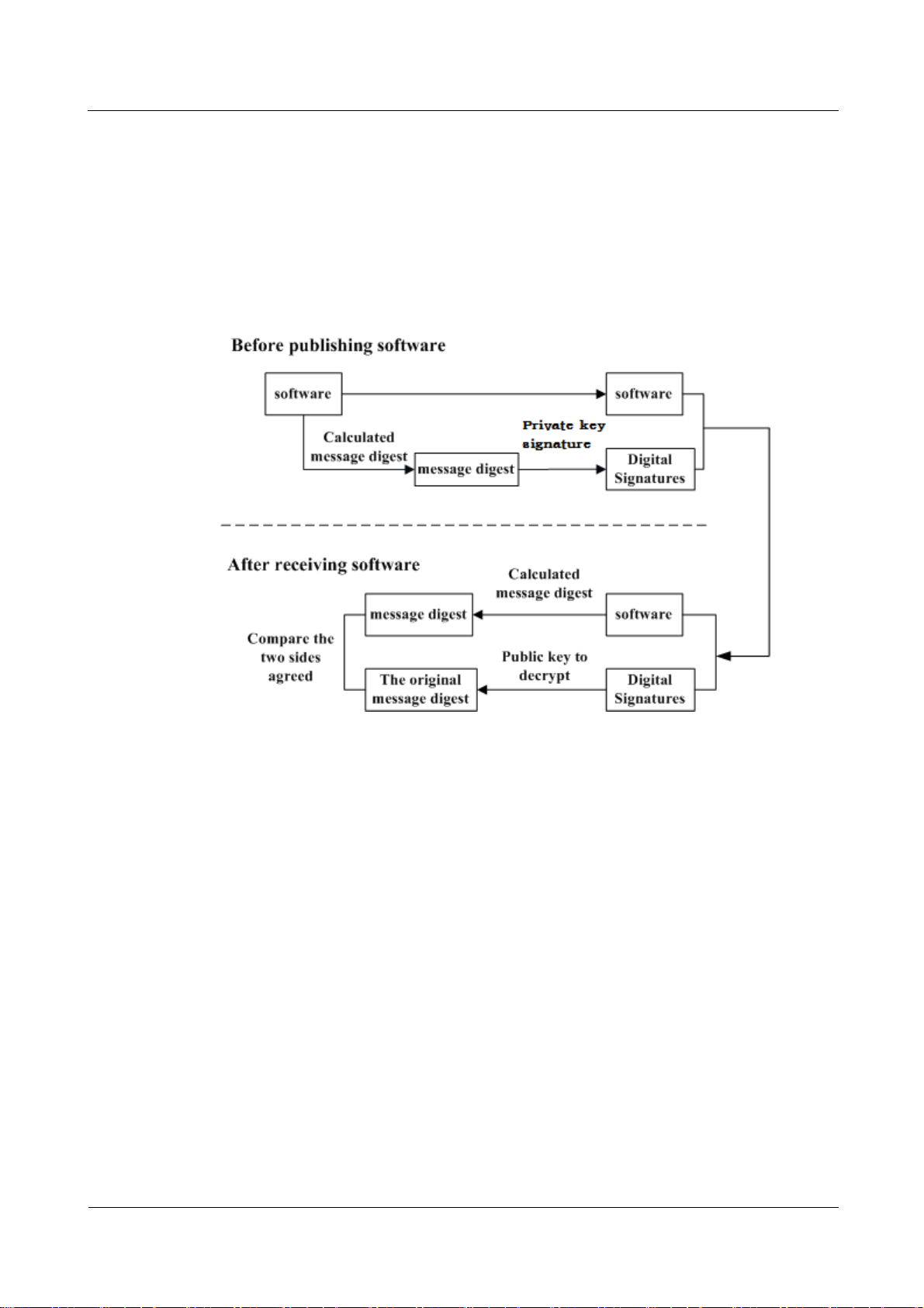
used. Figure 1-5 illustrates the principles of a software digital signature.
Figure 1-5 Digital signature of software
Before a software package is released, all files in the software package are signed with
digital signatures. That is, after a message digest is calculated for all files in the software
package, the message digest is digitally signed using a private key.
After a software package with a digital signature is loaded to an NE through a media
such as the software release platform, the NE first verifies the digital signature of the
software package. That is, the NE uses a public key to decrypt the digital signature and
obtain the original message digest. Then, the NE recalculates the message digest and
compares the new message digest with the original one.
− If the two message digests are the same, the software package passes the
verification and can be used.
− If the two message digests are different, the software package fails the verification
and cannot be used.
The public key used to decrypt digital signatures is stored in the secure storage area of an NE
and cannot be queried or exported.

eA680-950 LTE DAU
User Guide
1 Overview
Issue 01 (2017-03-03)
Huawei Proprietary and Confidential
Copyright © Huawei Technologies Co., Ltd.
10
1.7 Device Ports
1.7.1 Web Port
You can log in to the DAU web UI over HTTPS to manage the DAU, including configuring
and querying settings, exporting running logs, querying device logs, importing and exporting
the configuration, restarting and updating the DAU, and restoring the DAU to its default
settings. For details, see the web UI online help.
The default web UI login user name and password are admin and admin, respectively.
You can change the login password on the web UI.
Internet Explorer 7.0 and a later version is recommended, because Internet Explorer 6.0 uses the SSL 3.0
protocol that contains vulnerabilities.
To improve security, change the default password at your first login and regularly change the password.
A password must meet the following rules:
A password consists of 8 to 15 characters.
A password contains at least three types of characters of the following:
− Lowercase letter
− Uppercase letter
− Digit
− Special characters, including the space character and the following:
A password cannot be the user name or the reverse order of the user name.
A password cannot contain more than two consecutive characters that are the same (for example, 111
is not allowed.)
`~!@#$%^&*()-_=+\|[{}];:'",<.>/?
By default, the function to remotely log in to the DAU web UI over HTTPS is disabled. The
remote web UI functions the same as the local web UI.
The maximum number of WebUI login attempts is three. After three login failures, the WebUI login
page is locked and will be unlocked after one minutes. The lockingduration is incremented by one
minute each time the WebUI login page is locked later.
When the WebUI login password is forgotten, contact the device agent or maintenance center to
restore factory defaults; refer to the AT command manual to restore factory defaults by yourself; or
contact the device operator to reset the password through TR-069.
The WebUI supports remote (LTE wireless link) and local (Ethernet interface or Wi-Fi link) login.
Please configure ACL rights based on scenarios to control remote and local WebUI login. Opening
unnecessary login interfaces may increase network attack risks or lead to unauthorized login. You
can use the ACL service to enable or disable remote or local WebUI login. For details, see the
section "Service Control List" in the online help of the device WebUI.
If you do not perform any operation within 5 minutes after logging in to the WebUI, the system
automatically logs you out..
You are advised to change the password timely after first login and regularly change the password to
improve network security.
Personnel in the central office may remotely log in to the LTE DAU WebUI for DAU management
and upgrade using HTTPS.
DAUs support HTTPS and are compatible with HTTP. HTTP is not a relatively secure protocol.
eA680-950 LTE DAU
User Guide
1 Overview
Issue 01 (2017-03-03)
Huawei Proprietary and Confidential
Copyright © Huawei Technologies Co., Ltd.
11
1.7.2 USB Port
Port Mapping Name on
the Computer
Port Usage
Port Number
HUAWEI Mobile Connect PC UI Interface
Used to run AT commands.
0x12(the actual computer
port prevails)
In normal cases, the USB port works in slave mode. In slave mode, the USB port will be
mapped to a computer UI after the Huawei-provided chip driver is installed on the computer.
This UI is locked by default. You can run other AT commands and write data to the SoftSim
card only after running the unlock command. After the serial port mapped by the USB is
connected successfully, run the unlock command.
The commands for unlocking the computer UI port and changing the unlock password are as
follows
at^PCPORT=”pwd”,1: Enable the computer UI. pwd indicates the unlock password.
at^PCPORT=”pwd”,0: Disable the computer UI. pwd indicates the unlock password.
at^PORTPWD=”oldPwd”,”newPwd”, “newPwdConf”: Change the unlock password of
the computer UI. Here, oldPwd indicates the current password, and newPwd the new
password, and newPwdConf the confirm password. newPwd must be the same as
newPwdConf; otherwise, the password cannot be changed.
The default unlock password is $Zls123Q.
To improve security, change the default USB unlock password at your first login and regularly change
the password.
A password must meet the following rules:
A password consists of at least eight characters.
A password contains at least three types of characters of the following:
− Lowercase letter
− Uppercase letter
− Digit
− Special characters, including the space character and the following:
`~!@#$%^&*()-_=+|[{}];:,<.>?
The password cannot be the user name or the reverse order of the user name.
A password cannot contain more than two consecutive characters that are the same (for example, 111
is not allowed.)
When the PC UI is unlocked, you can run commands to unlock other USB ports or AT
commands to map the ports in the following table.
To learn more about AT commands, contact your device vendor or the maintenance center.
The chipset driver supporting the USB interface is the host driver that supports Huawei
Balong V7R1. If you need it, contact Huawei.
The maximum number of unlock the USB port attempts is five. After five attempt failures, users
cannot input any key. Users have to restart the device.
The maximum number of password change attempts is five. After five attempt failures, the USB
ports will be locked.

eA680-950 LTE DAU
User Guide
1 Overview
Issue 01 (2017-03-03)
Huawei Proprietary and Confidential
Copyright © Huawei Technologies Co., Ltd.
12
1.7.3 TR-069 Port
Personnel in the central office can manage the DAU remotely using TR-069.
The management functions include device configuration, configuration query, running
log exporting, and device updating.
The account used for connections between the DAU and central office management
equipment is managed by personnel in the central office. The default account name and
passwords are admin and Changeme123, respectively.
MD5 digest authentication is used for connections between the DAU and central office
management equipment, and the authentication complies with TR-069 Amendment 4.
Ensure that the settings for the DAU and central office TR-069 management equipment are the same.
Otherwise, the DAU cannot be managed by the central office TR-069 management equipment.
It is recommended that you change the password for connections between the DAU and central office
TR-069 management equipment at regular intervals. You can change the password on the TR–069
management page.
A password must meet the following rules:
− Lowercase letter
− Uppercase letter
− Digit
− Special characters, including the space character and the following:
After USB ports are unlocked, the USB ports do not support logout upon timeout and do not exit the
unlock state even if the ports are removed. In this context, perform the operation in a secure
environment and restart the device, or run commands to lock the USB ports.
If the softsim tool is provided by Huawei, please apply the license of the tool from Huawei, and
notice the usage scope. For details of apply guide,see SoftSim Tool License Operation Guide.
You are advised to change the password timely after first login and regularly change the password to
improve network security.
It is recommended that you set the password length of 6 to 100 characters (a password consists of 6
to 100 characters).
A password contains at least three types of characters of the following:
`~!@#$%^&*()-_=+\|[{}];:'",<.>/?
A password cannot be the user name or the reverse order of the user name.
A password cannot contain more than two consecutive characters that are the same (for example, 111
is not allowed.)
When TR-069 network management is enabled, each registration of the DAU will generate
about 70 KB of data traffic, each periodic reporting will generate about 20 KB of data traffic,
and the data traffic generated by each update depends on the update package size. An update
package is generally smaller than 100 MB, and updates are triggered by the central office
management equipment.
When TR-069 network management is enabled, the DAU regularly connects to the central
office management equipment, and the connection cycle complies with TR-069 Amendment
4.

eA680-950 LTE DAU
User Guide
1 Overview
Issue 01 (2017-03-03)
Huawei Proprietary and Confidential
Copyright © Huawei Technologies Co., Ltd.
13
Devices support reporting the following Alarms:
Lower computer disconnection alarm
LAN upstream exception alarm
Poor wireless coverage alarm
Login and logout alarm
Threshold-crossing lower computer alarm
Digest authentication prevents the account and password used for connections between the DAU and
central office TR-069 management equipment from being cracked. The number of attempts is five.
After five attempt failures, wait five minutes and receive new connection authentication requests.
The central office TR-069 management equipment will use the SN as the unique identifier for device
management.

eA680-950 LTE DAU
User Guide
2 Hardware
Issue 01 (2017-03-03)
Huawei Proprietary and Confidential
Copyright © Huawei Technologies Co., Ltd.
14
About This Chapter
This section describes the hardware and cables of the eA680-950.
2.1 eA680-950 Hardware
2 Hardware
Appearance
This section describes the appearance, ports, and indicators of the eA680-950.
Figure 2-1 shows the appearance of the eA680-950.
Figure 2-1 Appearance of eA680-950s

eA680-950 LTE DAU
User Guide
2 Hardware
Issue 01 (2017-03-03)
Huawei Proprietary and Confidential
Copyright © Huawei Technologies Co., Ltd.
15
Panel
Name
Description
PoE
PoE port
LED
Indicators
SIM card maintenance window
Consists of the SIM card slot and USB port.
A SIM card is inserted into the SIM card
slot.
The USB port is used for internal
commissioning.
Grounding end
Connects a ground cable
The panel of the eA680-950 provides the Power over Ethernet (PoE) port, SIM card
maintenance window, and indicator.
Figure 2-2 shows the panel of the eA680-950.
Figure 2-2 Panel of the eA680-950
Table 2-1 lists the ports of the eA680-950.
Table 2-1 Ports on the eA680-950

eA680-950 LTE DAU
User Guide
2 Hardware
Issue 01 (2017-03-03)
Huawei Proprietary and Confidential
Copyright © Huawei Technologies Co., Ltd.
16
Name
Description
Nameplate
Displays the identifier information of a
vendor
Anti-scalding label
Anti-scalding sign
External antenna interface
NOTE
Only supports dual-polarized antenna or dual
antenna installation.
Identifier
Status
Description
POWER
On
The power supply is normal.
Off
No power is supplied.
WLINK
Steady on
The eA680-950 is successfully
registered to the network.
Indicators of the eA680-950 are below the SIM card maintenance window and are used to
indicate the running status of the eA680-950.
The four indicators from top to bottom are POWER, WLINK, RSSI, and HEAT, as shown in
Figure 2-3.
Figure 2-3 Indicators
Table 2-2 describes the indicators of the eA680-950.
Table 2-2 Indicators of the eA680-950

eA680-950 LTE DAU
User Guide
2 Hardware
Issue 01 (2017-03-03)
Huawei Proprietary and Confidential
Copyright © Huawei Technologies Co., Ltd.
17
Identifier
Status
Description
Blink per 1000 ms
The product fails to register to the
network.
RSSI
NOTE
The blink frequency
of the RSSI indicator
on the panel is
determined by the
valve of the reference
signal received power
(RSRP).
Steady on
The signal strength ranges from –40
dBm to –60 dBm.
Blink per 500 ms
The signal strength ranges from –60
dBm to –80 dBm.
Blink per 1000 ms
The signal strength ranges from –80
dBm to –105 dBm.
Blink per 2000 ms
The signal strength ranges from -105
dBm to -120 dBm.
Off
The signal strength is equal to or
smaller than –120 dBm.
HEAT
Controlled by the
hardware temperature.
When the hardware temperature is
lower than 0°C, the hardware is heated
and the indicator is on.
When the hardware temperature is
higher than 0°C, the indicator is off.
Name
Description
Color
Black
Outer diameter
6.8 mm
Working temperature range
–40°C to 75°C
2.2 eA680-950Cables
2.2.1 PoE Network Cable
The power over ethernet (PoE) network cable is a shielded network cable that is used to
connect the PoE port of the eA680-950. The PoE network cable connects to an RJ45
connector at both ends.
Background Information
The PoE network cable transmits data signals to the eA680-950 and provides DC power for
the equipment.
Technical Specifications
Table 2-3 lists the technical specifications of the PoE network cable.
Table 2-3 Technical specifications of the PoE network cable

eA680-950 LTE DAU
User Guide
2 Hardware
Issue 01 (2017-03-03)
Huawei Proprietary and Confidential
Copyright © Huawei Technologies Co., Ltd.
18
Name
Description
Color
Yellow-green
Cross-section
6 mm²
Outer diameter
5.1 mm
Working temperature range
–10°C to 70°C
2.2.2 Ground Cable
The ground cable ensures the proper grounding of the eA680-950.
Appearance
The ground cable provides a 6 mm² cross-section, is yellow-green, and has OT terminals at
both ends. Figure 2-4 shows the appearance of the ground cable.
Figure 2-4 Ground cable
Technical Specifications
Table 2-4 lists the technical specifications of the ground cable.
Table 2-4 Technical specifications of the ground cable

eA680-950 LTE DAU
User Guide
3 Installation
Issue 01 (2017-03-03)
Huawei Proprietary and Confidential
Copyright © Huawei Technologies Co., Ltd.
19
About This Chapter
This section describes how to install the eA680-950.
3.1 Site Preparations
3 Installation
This section describes how to prepare a site before eA680-950 installation.
Select a site and space for installing an eA680-950 that meets the following requirements to
ensure installation, commissioning, and operating of the equipment.
Requirements for Site Selection
To ensure long-term reliability of an eA680-950, select a site based on the network plan and
technical requirements of the equipment, as well as considerations such as hydrology, geology,
and transportation.
Site selection must meet the following requirements:
Keep the site away from high temperature, dusty location, poisonous gases, explosive
objects, and unstable voltages.
Keep the site away from any electric substation, industrial boiler, and heating boiler.
Keep the site away from any radar station, large-power radio transmitting station, and
other interference sources. The field strength of interference sources cannot exceed that
of unwanted radiation that an eA680-950 can shield.
Keep an outdoor eA680-950 site 500 m away from the sea.
Keep the site away from pollution sources. If this is not possible, deploy the site in
perennial upwind direction of pollution sources.
Keep the site at least 5 km away from heavy pollution sources such as a refinery and coal
mine.
Keep the site at least 3.7 km away from moderate pollution sources such as a chemical
plant, a rubber plant, and an electroplating factory.
Keep the site at least 2 km away from light pollution sources such as a food factory and a
leather processing plant.

eA680-950 LTE DAU
User Guide
3 Installation
Issue 01 (2017-03-03)
Huawei Proprietary and Confidential
Copyright © Huawei Technologies Co., Ltd.
20
The air intake vents of the communication equipment must be far away from the sewer
pipe, septic tank, and sewage disposal pool. The atmospheric pressure inside the
equipment room must be higher than that outside the equipment room. Otherwise,
corrosive gases may enter the equipment room and corrode the components and circuit
boards.
Keep indoor eA680-950 sites away from livestock rearing houses and fertilizer
warehouses. If this is not possible, the room must be located at a place that is in the
upwind direction of the livestock room or fertilizer warehouse.
Deploy an indoor eA680-950 site higher than the second floor in a building.
Alternatively, mount an eA680-950 at least 600 mm higher than the record flood stage.
Requirements for Installation Space
To facilitate O&M, adhere to the following space requirements as shown in Figure 3-1.
Figure 3-1 Space requirements for installing an eA680-950 (unit: mm)
Requirements for Operating Environment
For details about operating environment requirements, see1.3 Hardware Specifications
3.2 Installation Preparation
Before you install the eA680-950, unpack and inspect the equipment delivered to the site and
prepare the related tools.
Prerequisites
Perform the following operations to inspect the goods delivered to the site:
1. Unpack the equipment, count the total number of items based on the packing list
attached to each packing case, and check whether each packing case is intact.
2. Check whether the models and quantities are consistent with those specified on the
Packing List.
3. Record the serial number of the DAU.

eA680-950 LTE DAU
User Guide
3 Installation
Issue 01 (2017-03-03)
Huawei Proprietary and Confidential
Copyright © Huawei Technologies Co., Ltd.
21
Precautions
Hammer drill
ESD gloves
Vacuum cleaner
Heat gun
Phillips screwdriver
(M3–M6)
Flat-head screwdriver
(M3–M6)
Claw hammer
Utility knife
Wire stripper
Power cable crimping tool
Cable cutter
Adjustable wrench (open end
≥32 mm)
Vise
Hex key (M5,M6)
Phillips torque screwdriver
Installation Tools
Table 3-1 lists the tools used for installing the eA680-950.
Table 3-1 Installation tools
Power on a DAU within 24 hours after unpacking it. If you power off a DAU for
maintenance, restore power to the DAU within 24 hours. Keep the DAU dry in humid
environment.
To avoid direct lightning, DAU must be installed in the protection angle of 45 degrees
below a separate lightning rod, or protection angle of 45 degrees below a surrounding
high-rise building.
Ensure that there are no obstacles facing the DAU, and enable the DAU to face the base
station.

eA680-950 LTE DAU
User Guide
3 Installation
Issue 01 (2017-03-03)
Huawei Proprietary and Confidential
Copyright © Huawei Technologies Co., Ltd.
22
Measuring tape
Multimeter
Marker (diameter ≤ 10 mm)
3.3 Installation Procedure
3.3.1 Mounting on a Utility Pole
Context
Figure 3-2 shows the flowchart for mounting the eA680-950 on a utility pole without an angle
adjusting component.
Figure 3-2 Flowchart for mounting the eA680-950 on a utility pole without an angle adjusting
component

eA680-950 LTE DAU
User Guide
3 Installation
Issue 01 (2017-03-03)
Huawei Proprietary and Confidential
Copyright © Huawei Technologies Co., Ltd.
23
Procedure
Step 1 Open the SIM card maintenance window of the eA680-950 and insert the SIM card, as shown
in Figure 3-3.
Figure 3-3 Installing the SIM card
Figure 3-4 shows the correct installation method.
Figure 3-4 Installation method of the SIM card maintenance window

eA680-950 LTE DAU
User Guide
3 Installation
Issue 01 (2017-03-03)
Huawei Proprietary and Confidential
Copyright © Huawei Technologies Co., Ltd.
24
When you install the SIM card maintenance window, insert the protrusion into the caging slot
to ensure that the SIM card maintenance window is waterproof. Do not fasten the screws until
the SIM card maintenance window has been correctly installed.
Step 2 Insert the hose clamp to the wall-mounting frame, as shown in Figure 3-5.
Figure 3-5 Inserting the hose clamp to the wall-mounting frame
Insert the end of the hose clamp that does not contain a screw into the square hole on top of the
wall-mounting frame on the back of the unit. When half of the hose clamp passes through the square
hole, slightly kink the protruding part and insert it into the other square hole on the front of the unit.
Step 3 Install the hose clamp with the wall-mounting frame on the utility pole, and use a M6 hex key
to rotate the screw on the hose clamp to adjust the length of the hose clamp until it is correctly
connected, as shown in Figure 3-6.

eA680-950 LTE DAU
User Guide
3 Installation
Issue 01 (2017-03-03)
Huawei Proprietary and Confidential
Copyright © Huawei Technologies Co., Ltd.
25
Figure 3-6 Adjusting the length of the hose clamp
If the hose clamp is too long, cut off the extra part. Apply anti-rust oil to the cut in case it gets
rusty.
Step 4 Fix the eA680-950 on the wall-mounting frame through the dovetail groove, as shown in
Figure 3-7.
Figure 3-7 Installing the eA680-950 on the wall-mounting frame
Step 5 Tighten the wall-mounting frame's screw, as shown in Figure 3-8.

eA680-950 LTE DAU
User Guide
3 Installation
Issue 01 (2017-03-03)
Huawei Proprietary and Confidential
Copyright © Huawei Technologies Co., Ltd.
26
Figure 3-8 Tightening the screw
----End
3.3.2 Mounting on the Wall
Context
Figure 3-9 shows the flowchart for mounting the DAU on the wall.

eA680-950 LTE DAU
User Guide
3 Installation
Issue 01 (2017-03-03)
Huawei Proprietary and Confidential
Copyright © Huawei Technologies Co., Ltd.
27
Figure 3-9 Wall-mounting flowchart
Procedure
Step 1 Open the SIM card maintenance window of the eA680-950 and insert the SIM card, as shown
in Figure 3-10.

eA680-950 LTE DAU
User Guide
3 Installation
Issue 01 (2017-03-03)
Huawei Proprietary and Confidential
Copyright © Huawei Technologies Co., Ltd.
28
Figure 3-10 Installing the SIM card
Figure 3-11 shows the correct installation method.
Figure 3-11 Installation method of the SIM card maintenance window

eA680-950 LTE DAU
User Guide
3 Installation
Issue 01 (2017-03-03)
Huawei Proprietary and Confidential
Copyright © Huawei Technologies Co., Ltd.
29
When you install the SIM card maintenance window, insert the protrusion into the caging slot
to ensure that the SIM card maintenance window is waterproof. Do not fasten the screws until
the SIM card maintenance window has been correctly installed.
Step 2 Hold the wall-mounting frame tightly against the wall, use a level to adjust the horizontal
position, and mark the fixing points with a marker, as shown in Figure 3-12.
Figure 3-12 Marking the fixing points
Step 3 Use a drill with 8 mm drill bit to drill holes in the fixing points. Then remove the dust from
the holes and install the expansion bolts, as shown in Figure 3-13.

eA680-950 LTE DAU
User Guide
3 Installation
Issue 01 (2017-03-03)
Huawei Proprietary and Confidential
Copyright © Huawei Technologies Co., Ltd.
30
Figure 3-13 Installing the expansion bolt
Step 4 Align the two fixing points with the bolts on the wall and tighten the expansion bolt's screw
nut to fix the wall-mounting frame, as shown in Figure 3-14.
Figure 3-14 Fixing the wall-mounting frame
Step 5 Install the ground cable. For details, see Step 1 in Cable Connection.
Step 6 Fix eA680-950 to the wall-mount frame using the dovetail groove, as shown in Figure 3-15.

eA680-950 LTE DAU
User Guide
3 Installation
Issue 01 (2017-03-03)
Huawei Proprietary and Confidential
Copyright © Huawei Technologies Co., Ltd.
31
Figure 3-15 Fixing the DAU
Step 7 Tighten the wall-mounting frame's screw, as shown in Figure 3-16.
Figure 3-16 Tightening the screw

eA680-950 LTE DAU
User Guide
3 Installation
Issue 01 (2017-03-03)
Huawei Proprietary and Confidential
Copyright © Huawei Technologies Co., Ltd.
32
----End
3.3.3 Cable Connection
This section describes the procedure for connecting the eA680-950 cables.
Procedure
Step 1 Connect the ground cable, as shown in Figure 3-17.
Figure 3-17 Connecting the ground cable
Tighten the ground screws and apply antirust paint to it.
Step 2 Install the crystal connector to PoE network cable, as shown in Figure 3-18.

eA680-950 LTE DAU
User Guide
3 Installation
Issue 01 (2017-03-03)
Huawei Proprietary and Confidential
Copyright © Huawei Technologies Co., Ltd.
33
Figure 3-18 Install crystal connector
When making PoE network cables, follow the international standard EIA/TIA568A or EIA/TIA568A to
arrange the cables. Make sure that the two ends of each network cable use the same standard.
Step 3 Connect the PoE network cable.
1. Diassemble the PG-head screw cap and air-proof block on the PoE port, and pass the
network cable through them, as shown in Figure 3-19.

eA680-950 LTE DAU
User Guide
3 Installation
Issue 01 (2017-03-03)
Huawei Proprietary and Confidential
Copyright © Huawei Technologies Co., Ltd.
34
Figure 3-19 Passing the network cable through the PG-head screw cap and air-proof block
2. Connect the network cable to the network adapter, and manually rotate the screw cap to
ensure that the lock block adheres to the network cable, as shown in Figure 3-20.
Figure 3-20 Installing the PG-head screw cap and air-proof block
Step 4 Connect the PoE adapter.

eA680-950 LTE DAU
User Guide
3 Installation
Issue 01 (2017-03-03)
Huawei Proprietary and Confidential
Copyright © Huawei Technologies Co., Ltd.
35
Connect one end of the PoE network cable to the adapter, as shown in Figure 3-21.
1. DATA port: connects to the compuer
network cable.
2. PoE port: connects to the PoE network
cable.
No.
Check Item
Figure 3-21 Connecting the PoE adapter
----End
3.4 Installation Check
After you install the eA680-950, perform a hardware installation check and a power-on check.
Prerequisites
The eA680-950 hardware has been installed.
Procedure
Step 1 Check whether the eA680-950 hardware is correctly installed.
When performing the hardware check for the eA680-950, check the items listed in Table 3-2
in order.
Table 3-2 Hardware installation check of the eA680-950

eA680-950 LTE DAU
User Guide
3 Installation
Issue 01 (2017-03-03)
Huawei Proprietary and Confidential
Copyright © Huawei Technologies Co., Ltd.
36
No.
Check Item
1
The installation position must strictly comply with the design
drawings, meet the installation space requirements, and reserve space
for maintenance.
2
When the eA680-950 is mounted on a metal utility pole, the fixture
must be firmly installed, and the DAU must be attached.
3
When the eA680-950 is mounted on the wall, the installation hole on
the fixture must be aligned with the one on the expansion bolt. In
addition, the fixture must be tightly and firmly attached to the wall and
must not wobble when you shake it.
No.
Check Item
1
No cable is short-circuited or inversely connected.
2
The bare wires and lugs of the connecting terminal must be tightly
wrapped with insulation tapes. Cooper wires must not be exposed.
3
Power cables or PGND cables with connectors are not used.
4
The connector of the PoE network cable must be appropriately
connected.
When checking the cable connections of the eA680-950, check the items listed in Table 3-3 in
order.
Table 3-3 Cable connection check of the eA680-950
Step 2 Perform the power-on check, as shown in Figure 3-22.

eA680-950 LTE DAU
User Guide
3 Installation
Issue 01 (2017-03-03)
Huawei Proprietary and Confidential
Copyright © Huawei Technologies Co., Ltd.
37
Figure 3-22 Power-on check of the eA680-950
No.
Check Item
1
When the eA680-950 powers on, the POWER indicator is on.
2
When the eA680-950 powers on, the RSSI indicator is steady
on or blinks.
The items listed in Table 3-4 must be checked during eA680-950 indicator check.
Table 3-4 Indicator check
If the RSSI indicator is off when the eA680-950 powers on, the signal strength is too weak. Check the
power supply and the angle of the angle adjusting component. For details about the indicator status, see
2.1 eA680-950 Hardware.
----End

eA680-950 LTE DAU
User Guide
4 Configuration Introduction
Issue 01 (2017-03-03)
Huawei Proprietary and Confidential
Copyright © Huawei Technologies Co., Ltd.
38
4 Configuration Introduction
About This Chapter
This chapter describes the configuration Introduction of the eA680-950s.
4.1 Log in to the WebUI
Prerequisites
Procedure
Step 1 Start the IE browser, enter http://192.168.1.1 in the address bar, and press Enter. Connect the
Step 2 Log in to the web management page with User name set to default value admin and
Step 3 Access Password Modification and modify New Password.
The deployment on the network side is complete.
The computer has been connected to the eA680-950.
The installation of the eA680-950 is complete.
The eA680-950 starts correctly based on default parameters during power-on.
eA680-950 from the near end using the Web management page.
Use Internet Explorer 7.0 or a later version.
Password set to default value admin.
----End

eA680-950 LTE DAU
User Guide
5 Maintenance
Issue 01 (2017-03-03)
Huawei Proprietary and Confidential
Copyright © Huawei Technologies Co., Ltd.
39
About This Chapter
This section describes the maintenance preparation and fault diagnosis methods for the
eA680-950.
5 Maintenance
5.1 Maintenance Preparation
Before performing site maintenance for the eA680-950, learn about the sit information, select
required maintenance items, and prepare related tools.
Learning About the Site Information
Gather the following site information before going to the eA680-950 site to perform
maintenance.
Persisting faults and alarms
Hardware configuration
Natural environment
Selecting Maintenance Items
Select suitable maintenance items based on the eA680-950 site conditions.
Maintenance items must include the following aspects:
Natural environment of the eA680-950 site
Power and grounding systems of the eA680-950
eA680-950
5.2 Fault Diagnosis
When the DAU does not run properly, use the tools on the Web management page to perform
initial diagnosis.

eA680-950 LTE DAU
User Guide
5 Maintenance
Issue 01 (2017-03-03)
Huawei Proprietary and Confidential
Copyright © Huawei Technologies Co., Ltd.
40
Prerequisites
Procedure
Step 1 Start the IE browser, enter http://192.168.1.1 in the address bar, and press Enter. Log in to
Step 2 Choose Settings > TR-069 Management> Diagnosis to open the Diagnosis page.
Step 3 Set Diagnosis Method to Ping.
Step 4 Enter the domain name in the Destination IP address/domain name box.
Step 5 Click Apply.
The network deployment is complete.
The computer has been connected to the eA680-950.
The installation of the eA680-950 is complete.
The eA680-950 starts appropriately based on default parameters after power-on.
When the LTE CPE fails to access the Internet, run the Ping function to quickly check
the network connection status.
the Web management page, and enter User name and Password.
Use Internet Explorer 7 (IE7) or a later version.
Step 6 Wait until the operation is performed. The command output is displayed in the Result box.
Timeout indicates the timeout period of each reply, and ranges from 1 to 10 seconds.
When the LTE CPE does not run properly, the System Check can be used to
preliminarily identify the problem.
Step 7 Start the IE browser, enter http://192.168.1.1 in the address bar, and press Enter. Then enter
the correct password and click Log In.
Use Internet Explorer 7 (IE7) or a later version.
Step 8 Choose Settings > TR-069 Management> Diagnosis to open the Diagnosis page.
Step 9 Set Diagnosis Method to System Check.
Step 10 Click Check.
Step 11 Wait until the system check is performed. Click Export to export the detailed information to
the computer. If necessary, send the detailed information to maintenance personnel.
----End

eA680-950 LTE DAU
User Guide
6 FAQ
Issue 01 (2017-03-03)
Huawei Proprietary and Confidential
Copyright © Huawei Technologies Co., Ltd.
41
6 FAQ
6.1 What Do I Do If the Web UI Fails to Be Opened?
Problem Description:
I cannot visit theWeb management page of eA680-950 through browser.
Solution:
Step 1 Check wheather the DAU is powered on.
Step 2 Check wheather the cables are not properly connected.
Step 3 Check wheather the IP address is entered correctly.
Step 4 If there is no problem after the above checks, try to restart the DAU from the near end.
Step 5 If the problem persists, please contact Huawei technical engineer.
----End
6.2 What Do I Do When Power Indicator Is Not Working?
Problem Description:
Power indicator is not working
Solution:
Step 1 Check whether the PoE cable is correctly connected to the power. The power supply is
provided if the Power indicator presents red light.
Step 2 Check whether the PoE power adapter meets the product specifications.

eA680-950 LTE DAU
User Guide
6 FAQ
Issue 01 (2017-03-03)
Huawei Proprietary and Confidential
Copyright © Huawei Technologies Co., Ltd.
42
The PoE is powered by the DAU using item 02220015 as the power adapter.
The minimum input voltage: 90 V
The maximum input voltage: 264 V
Rate output voltage or current: 54 V or 650 mA
Output voltage accuracy: 5%
Input or output cable connector: AC 2pin or RJ45 8pin
----End
6.3 What Do I Do When the Data Service Is not Provided?
Problem Description:
Data service is not provided
Solution:
Step 1 Check whether the DAU is powered. If the Power indicator presents red light, the power
supply is provided.
Step 2 Check whether the SIM card is correctly installed.
Step 3 Confirm whether the DAU is connected to the network. Check whether the RSSI indicator is
steady or blinking.
Step 4 If the problem persists, contact local service provider.
----End

eA680-950 LTE DAU
User Guide
7 Privacy and Security
Issue 01 (2017-03-03)
Huawei Proprietary and Confidential
Copyright © Huawei Technologies Co., Ltd.
43
7.1 Privacy Policy
To better understand how we protect your personal information, please see the privacy policy
at http://consumer.huawei.com/privacy-policy.
The device will use the SN as the unique identifier for device management.
The device provides the log function to records device running and operation information,
excluding any information related to individuals, including the IMEI, IMSI, call record (in
voice scenarios), account, and password.
7 Privacy and Security
The device provides TR-069-based network management function. To disable this function,
see the TR-069-related section in the online help.
7.2 Security Maintenance
Software components used by this device may report vulnerabilities. This device will use the
software upgrade mode to fix these issues. You can obtain specific software packages from
the device agent.
7.3 Performing Default Security Configuration
After a WebUI login, users can check the online help to perform default security
configuration.
Change the WebUI login password, keep it secure, and regularly change it subsequently.
Verify that the TR-069 port password meets complexity requirements.
Set the firewall level to low and enable the anti-DoS attack function.
Configure the service list control function based on product application scenarios. If
HTTPS and ICMP access requests on the WAN side do not exist, disable WAN access.
Change the USB port password, keep it secure (before installation), and regularly change
it subsequently (optional).

eA680-950 LTE DAU
User Guide
7 Privacy and Security
Issue 01 (2017-03-03)
Huawei Proprietary and Confidential
Copyright © Huawei Technologies Co., Ltd.
44
The USB port provides maintenance and repair functions and allows you to set device
parameters. Please keep the password secure to prevent device parameters from being
modified or exposed.

eA680-950 LTE DAU
User Guide
8 FCC warning
Issue 01 (2017-03-03)
Huawei Proprietary and Confidential
Copyright © Huawei Technologies Co., Ltd.
45
8 FCC warning
This equipment has been tested and found to comply with the limits for a Class B digital device, pursuant to part
15 of the FCC Rules. These limits are designed to provide reasonable protection against harmful interference in a
residential installation. This equipment generates, uses and can radiate radio frequency energy and, if not installed
and used in accordance with the instructions, may cause harmful interference to radio communications. However,
there is no guarantee that interference will not occur in a particular installation. If this equipment does cause
harmful interference to radio or television reception, which can be determined by turning the equipment off and
on, the user is encouraged to try to correct the interference by one or more of the following measures:
—Reorient or relocate the receiving antenna. —Increase the separation between the equipment and receiver.
—Connect the equipment into an outlet on a circuit different from that to which the receiver is connected.
—Consult the dealer or an experienced radio/TV technician for help. MODIFICATION: Any changes or
modifications not expressly approved by the grantee of this device could void the user’s authority to operate the
device.
This device should be installed and operated with a minimum distance of 20cm between the antenna and all
persons.
MODIFICATION: Any changes or modifications not expressly approved by the grantee of this device could void
the user’s authority to operate the device.

eA680-950 LTE DAU
User Guide
9 Acronyms and Abbreviations
Issue 01 (2017-03-03)
Huawei Proprietary and Confidential
Copyright © Huawei Technologies Co., Ltd.
46
9 Acronyms and Abbreviations
Acronym/Abbreviation
Full Name
3GPP
3rd Generation Partnership Project
ARP
Address Resolution Protocol
DAU
Customer Premises Equipment
DHCP
Dynamic Host Configuration Protocol
DMZ
Demilitarized Zone
ICMP
Internet Control Message Protocol
IP
Internet Protocol
GRE
Generic Routing Encapsulation
LTE
Long Term Evolution
MAC
Media Access Control
MDI
Medium Dependent Interface
NAPT
Network Address Port Translation
NAT
Network Address Translation
RTU
Remote Terminal Unit
PoE
Power over Ethernet
SPI
Security Parameter Index
SIM
Subscriber Identity Module
TR069
Technical Report 069
URL
Uniform Resource Location
WAN
Wide Area Network
This section lists the acronyms and abbreviations related to the eA680-950.
Table 9-1 List of acronyms and abbreviations

eA680-950 LTE DAU
User Guide
9 Acronyms and Abbreviations
Issue 01 (2017-03-03)
Huawei Proprietary and Confidential
Copyright © Huawei Technologies Co., Ltd.
47
 Loading...