

Huawei CE6810-48S4Q-EI, CE6810-32T16S4Q-LI, CE6810-48S-LI, CE6810-24S2Q-LI, CE6810-48S4Q-LI operation manual
Page 1
CloudEngine 7800&6800&5800 Series Switches
Hardware Description
Issue 16
Date 2015-08-26
HUAWEI TECHNOLOGIES CO., LTD.
Page 2

Copyright © Huawei Technologies Co., Ltd. 2015. All rights reserved.
No part of this document may be reproduced or transmitted in any form or by any means without prior written
consent of Huawei Technologies Co., Ltd.
Trademarks and Permissions
and other Huawei trademarks are trademarks of Huawei Technologies Co., Ltd.
All other trademarks and trade names mentioned in this document are the property of their respective holders.
Notice
The purchased products, services and features are stipulated by the contract made between Huawei and the
customer. All or part of the products, services and features described in this document may not be within the
purchase scope or the usage scope. Unless otherwise specified in the contract, all statements, information,
and recommendations in this document are provided "AS IS" without warranties, guarantees or representations
of any kind, either express or implied.
The information in this document is subject to change without notice. Every effort has been made in the
preparation of this document to ensure accuracy of the contents, but all statements, information, and
recommendations in this document do not constitute a warranty of any kind, express or implied.
Huawei Technologies Co., Ltd.
Address: Huawei Industrial Base
Bantian, Longgang
Shenzhen 518129
People's Republic of China
Website: http://e.huawei.com
Issue 16 (2015-08-26) Huawei Proprietary and Confidential
Copyright © Huawei Technologies Co., Ltd.
i
Page 3
CloudEngine 7800&6800&5800 Series Switches
Hardware Description About This Document
About This Document
Intended Audience
This document describes hardware components of the CE7800&6800&5800 series switches,
including the chassis, power modules, fan modules, cables, and optical modules. You can find
useful information about CE7800&6800&5800 series switches hardware components from this
document.
This document is intended for:
l Network planning engineers
l Hardware installation engineers
l Commissioning engineers
l On-site maintenance engineers
l System maintenance engineers
Symbol Conventions
The symbols that may be found in this document are defined as follows.
Symbol Description
Indicates an imminently hazardous situation
which, if not avoided, will result in death or
serious injury.
Indicates a potentially hazardous situation
which, if not avoided, could result in death or
serious injury.
Indicates a potentially hazardous situation
which, if not avoided, may result in minor or
moderate injury.
Issue 16 (2015-08-26) Huawei Proprietary and Confidential
Copyright © Huawei Technologies Co., Ltd.
ii
Page 4
NOTE
CloudEngine 7800&6800&5800 Series Switches
Hardware Description
Symbol Description
Command Conventions
About This Document
Indicates a potentially hazardous situation
which, if not avoided, could result in
equipment damage, data loss, performance
deterioration, or unanticipated results.
NOTICE is used to address practices not
related to personal injury.
Calls attention to important information, best
practices and tips.
NOTE is used to address information not
related to personal injury, equipment damage,
and environment deterioration.
The command conventions that may be found in this document are defined as follows.
Convention Description
Boldface The keywords of a command line are in boldface.
Italic Command arguments are in italics.
[ ] Items (keywords or arguments) in brackets [ ] are optional.
{ x | y | ... } Optional items are grouped in braces and separated by
vertical bars. One item is selected.
[ x | y | ... ] Optional items are grouped in brackets and separated by
vertical bars. One item is selected or no item is selected.
{ x | y | ... }
[ x | y | ... ]
&<1-n> The parameter before the & sign can be repeated 1 to n times.
# A line starting with the # sign is comments.
*
*
Optional items are grouped in braces and separated by
vertical bars. A minimum of one item or a maximum of all
items can be selected.
Optional items are grouped in brackets and separated by
vertical bars. Several items or no item can be selected.
Declaration
This manual is only a reference for you to configure your devices. The contents in the manual,
such as command line syntax, and command outputs, are based on the device conditions in the
Issue 16 (2015-08-26) Huawei Proprietary and Confidential
Copyright © Huawei Technologies Co., Ltd.
iii
Page 5

CloudEngine 7800&6800&5800 Series Switches
Hardware Description
lab. The manual provides instructions for general scenarios, but do not cover all usage scenarios
of all product models. The contents in the manual may be different from your actual device
situations due to the differences in software versions, models, and configuration files. The
manual will not list every possible difference. You should configure your devices according to
actual situations.
The specifications provided in this manual are tested in lab environment (for example, the tested
device has been installed with a certain type of boards or only one protocol is run on the device).
Results may differ from the listed specifications when you attempt to obtain the maximum values
with multiple functions enabled on the device.
Change History
Changes between document issues are cumulative. The latest document issue contains all the
changes made in earlier issues.
Issue 16 (2015-08-26)
About This Document
This version has the following updates:
The following information is modified:
l 2 Chassis
l 3 Power Module
l 4 Fan Module
Issue 15 (2015-06-10)
This version has the following updates:
The following information is modified:
l 2.3 Appearance and Structure
l 6.2 SFP/SFP+ Modules
Issue 14 (2015-05-30)
This version has the following updates:
The following information is added:
l CE6810-32T16S4Q-LI
l CE6810-24S2Q-LI
l CE6850-48T6Q-HI
l CE6851-48S6Q-HI
l CE6850U-48S6Q-HI
l CE6850U-24S2Q-HI
l CE5855-48T4S2Q-EI
l CE5855-24T4S2Q-EI
l 150 W AC Power Module (ES0W2PSA0150)
Issue 16 (2015-08-26) Huawei Proprietary and Confidential
Copyright © Huawei Technologies Co., Ltd.
iv
Page 6

CloudEngine 7800&6800&5800 Series Switches
Hardware Description
l FAN-040A Series Fan Modules
Issue 13 (2015-04-26)
This version has the following updates:
The following information is modified:
l 2.3 Appearance and Structure
l 2.5 Ports
Issue 12 (2015-01-20)
This version has the following updates:
The following information is added:
l CE6850-48S6Q-HI
l 600 W AC&240 V DC Power Module
l 600 W High-Voltage DC Power Module
About This Document
l FAN-060A Series Fan Modules
Issue 11 (2014-12-01)
This version has the following updates:
The following information is modified:
l 2.3 Appearance and Structure
l 5.8 AOC Cable
Issue 10 (2014-09-20)
This version has the following updates:
The following information is added:
l CE6810-48S4Q-LI
l CE6810-48S-LI
Issue 09 (2014-08-01)
This version has the following updates:
The following information is modified:
l 1 Version Support for Components
l 3 Power Module
l 4 Fan Module
Issue 08 (2014-04-21)
This version has the following updates:
The following information is added:
Issue 16 (2015-08-26) Huawei Proprietary and Confidential
Copyright © Huawei Technologies Co., Ltd.
v
Page 7

CloudEngine 7800&6800&5800 Series Switches
Hardware Description
l CE7850-32Q-EI
l CE6810-48S4Q-EI
Issue 07 (2013-12-31)
This version has the following updates:
The following information is added:
l CE5850-48T4S2Q-HI
Issue 06 (2013-12-01)
This version has the following updates:
The following information is modified:
l 2.6 Specifications
Issue 05 (2013-11-20)
About This Document
This version has the following updates:
The following information is modified:
l 2.6 Specifications
Issue 04 (2013-10-15)
This version has the following updates:
The following information is modified:
l 3 Power Module
Issue 03 (2013-08-01)
This version has the following updates:
The following information is added:
l 3.4 350 W DC Power Module
l 3.5 600 W AC Power Module
l 4.2 FAN-40SB Series Fan Modules
l 5.2 DC Power Cable
The following information is modified:
l 2 Chassis
l 6 Optical Module
Issue 02 (2013-04-20)
This version has the following updates:
The following information is modified:
Issue 16 (2015-08-26) Huawei Proprietary and Confidential
Copyright © Huawei Technologies Co., Ltd.
vi
Page 8

CloudEngine 7800&6800&5800 Series Switches
Hardware Description About This Document
l 2.4 Indicators
Issue 01 (2013-03-15)
Initial commercial release.
Issue 16 (2015-08-26) Huawei Proprietary and Confidential
Copyright © Huawei Technologies Co., Ltd.
vii
Page 9

CloudEngine 7800&6800&5800 Series Switches
Hardware Description
Contents
Contents
About This Document.....................................................................................................................ii
1 Version Support for Components..............................................................................................1
1.1 Components Available in V100R001C00......................................................................................................................2
1.2 Components Available in V100R002C00......................................................................................................................3
1.3 Components Available in V100R003C00......................................................................................................................5
1.4 Components Available in V100R003C10......................................................................................................................7
1.5 Components Available in V100R005C00......................................................................................................................9
1.6 Components Available in V100R005C10....................................................................................................................12
2 Chassis...........................................................................................................................................17
2.1 Naming Conventions....................................................................................................................................................18
2.2 Version Mapping..........................................................................................................................................................19
2.3 Appearance and Structure.............................................................................................................................................20
2.4 Indicators......................................................................................................................................................................54
2.5 Ports..............................................................................................................................................................................75
2.6 Specifications................................................................................................................................................................81
2.7 Ordering Information....................................................................................................................................................97
3 Power Module............................................................................................................................105
3.1 150 W AC Power Module (PAC-150WA).................................................................................................................106
3.2 150 W AC Power Module (ES0W2PSA0150)...........................................................................................................110
3.3 350 W AC Power Module..........................................................................................................................................113
3.4 350 W DC Power Module..........................................................................................................................................118
3.5 600 W AC Power Module..........................................................................................................................................123
3.6 600 W AC&240 V DC Power Module.......................................................................................................................128
3.7 600 W High-Voltage DC Power Module...................................................................................................................134
4 Fan Module.................................................................................................................................139
4.1 FAN-40EA Series Fan Modules.................................................................................................................................140
4.2 FAN-40SB Series Fan Modules.................................................................................................................................143
4.3 FAN-40HA Series Fan Modules................................................................................................................................147
4.4 FAN-040A Series Fan Modules.................................................................................................................................151
4.5 FAN-060A Series Fan Modules.................................................................................................................................155
5 Cables...........................................................................................................................................160
Issue 16 (2015-08-26) Huawei Proprietary and Confidential
Copyright © Huawei Technologies Co., Ltd.
viii
Page 10

CloudEngine 7800&6800&5800 Series Switches
Hardware Description Contents
5.1 AC Power Cable.........................................................................................................................................................161
5.2 DC Power Cable.........................................................................................................................................................162
5.3 380 V High-Voltage DC Power Cable.......................................................................................................................164
5.4 Ground Cable..............................................................................................................................................................164
5.5 Console Cable.............................................................................................................................................................166
5.6 Network Cable............................................................................................................................................................167
5.7 Optical Fiber...............................................................................................................................................................172
5.8 AOC Cable.................................................................................................................................................................179
5.9 Copper Cable..............................................................................................................................................................180
6 Optical Module..........................................................................................................................185
6.1 Concepts.....................................................................................................................................................................186
6.2 SFP/SFP+ Modules.....................................................................................................................................................188
6.3 QSFP+ Modules.........................................................................................................................................................203
Issue 16 (2015-08-26) Huawei Proprietary and Confidential
Copyright © Huawei Technologies Co., Ltd.
ix
Page 11

CloudEngine 7800&6800&5800 Series Switches
Hardware Description 1 Version Support for Components
1 Version Support for Components
About This Chapter
NOTE
The availability of device models and modules described in this document will be specified in product
change notices (PCNs). For details, contact the product manager of Huawei local office.
The versions mentioned in this document refer to the software versions released for the
CE7800&6800&5800 series switches.
1.1 Components Available in V100R001C00
1.2 Components Available in V100R002C00
1.3 Components Available in V100R003C00
1.4 Components Available in V100R003C10
1.5 Components Available in V100R005C00
1.6 Components Available in V100R005C10
Issue 16 (2015-08-26) Huawei Proprietary and Confidential
Copyright © Huawei Technologies Co., Ltd.
1
Page 12
CloudEngine 7800&6800&5800 Series Switches
Hardware Description
1 Version Support for Components
1.1 Components Available in V100R001C00
Available Models
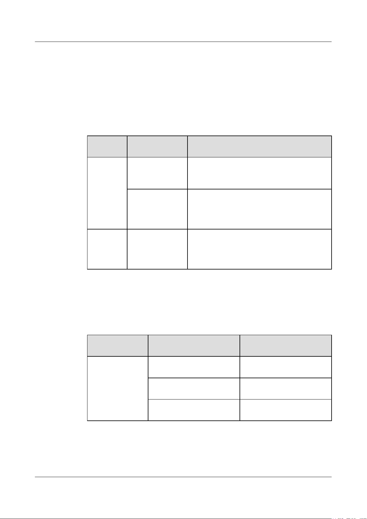
Table 1-1 lists the switch models available in V100R001C00.
Table 1-1 Models available in V100R001C00
Series Model Maximum Number of Ports Supported and Port
Description
CE6800 CE6850-48S4Q-EI 52 total:
48 10GE SFP+ optical ports, 4 40GE QSFP+ optical
ports (can be split into four 10GE ports)
CE6850-48T4Q-EI 52 total:
48 10GBASE-T Ethernet electrical ports, 4 40GE
QSFP+ optical ports (can be split into four 10GE
ports)
CE5800 CE5850-48T4S2Q-EI54 total:
Available Power Modules
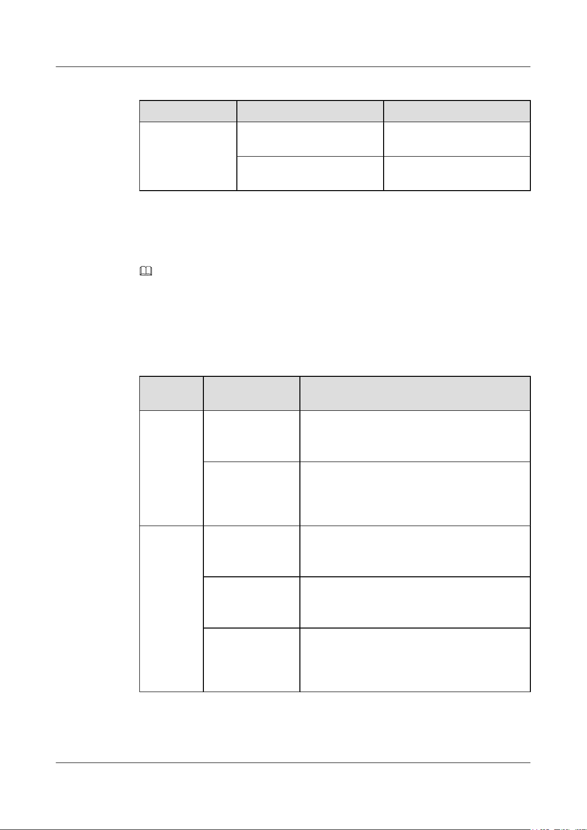
Table 1-2 lists the power modules available in V100R001C00.
Table 1-2 Power modules available in V100R001C00
Power Module
Type
AC power module PAC-150WA 150 W AC power module
48 10/100/1000BASE-T Ethernet electrical ports, 4
10GE SFP+ optical ports, 2 40GE QSFP+ optical ports
(cannot be split into four 10GE ports)
Power Module Power Description
(natural heat dissipation)
PAC-350WA-B 350 W AC power module (air
exhaust on front panel)
PAC-350WA-F 350 W AC power module (air
intake on front panel)
Available Fan Modules
Table 1-3 lists the fan modules available in V100R001C00.
Issue 16 (2015-08-26) Huawei Proprietary and Confidential
Copyright © Huawei Technologies Co., Ltd.
2
Page 13
CloudEngine 7800&6800&5800 Series Switches
Hardware Description
1 Version Support for Components
Table 1-3 Fan modules available in V100R001C00
Series Model Description
FAN-40EA FAN-40EA-B FAN-40EA (air exhaust on front
panel)
FAN-40EA-F FAN-40EA (air intake on front
panel)
1.2 Components Available in V100R002C00
NOTE
The components marked * are the new components added to V100R002C00.
Available Models
Table 1-4 lists the switch models available in V100R002C00.
Table 1-4 Models available in V100R002C00
Series Model Maximum Number of Ports Supported and Port
Description
CE6800 CE6850-48S4Q-EI 52 total:
48 10GE SFP+ optical ports, 4 40GE QSFP+ optical
ports (can be split into four 10GE ports)
CE6850-48T4Q-EI 52 total:
48 10GBASE-T Ethernet electrical ports, 4 40GE
QSFP+ optical ports (can be split into four 10GE
ports)
CE5800
CE5810-24T4S-EI
*
28 total:
24 10/100/1000BASE-T Ethernet electrical ports, 4
10GE SFP+ optical ports
*
CE5810-48T4S-EI
52 total:
48 10/100/1000BASE-T Ethernet electrical ports, 4
10GE SFP+ optical ports
CE5850-48T4S2Q-EI54 total:
48 10/100/1000BASE-T Ethernet electrical ports, 4
10GE SFP+ optical ports, 2 40GE QSFP+ optical ports
(cannot be split into four 10GE ports)
Issue 16 (2015-08-26) Huawei Proprietary and Confidential
Copyright © Huawei Technologies Co., Ltd.
3
Page 14
CloudEngine 7800&6800&5800 Series Switches
Hardware Description
Available Power Modules
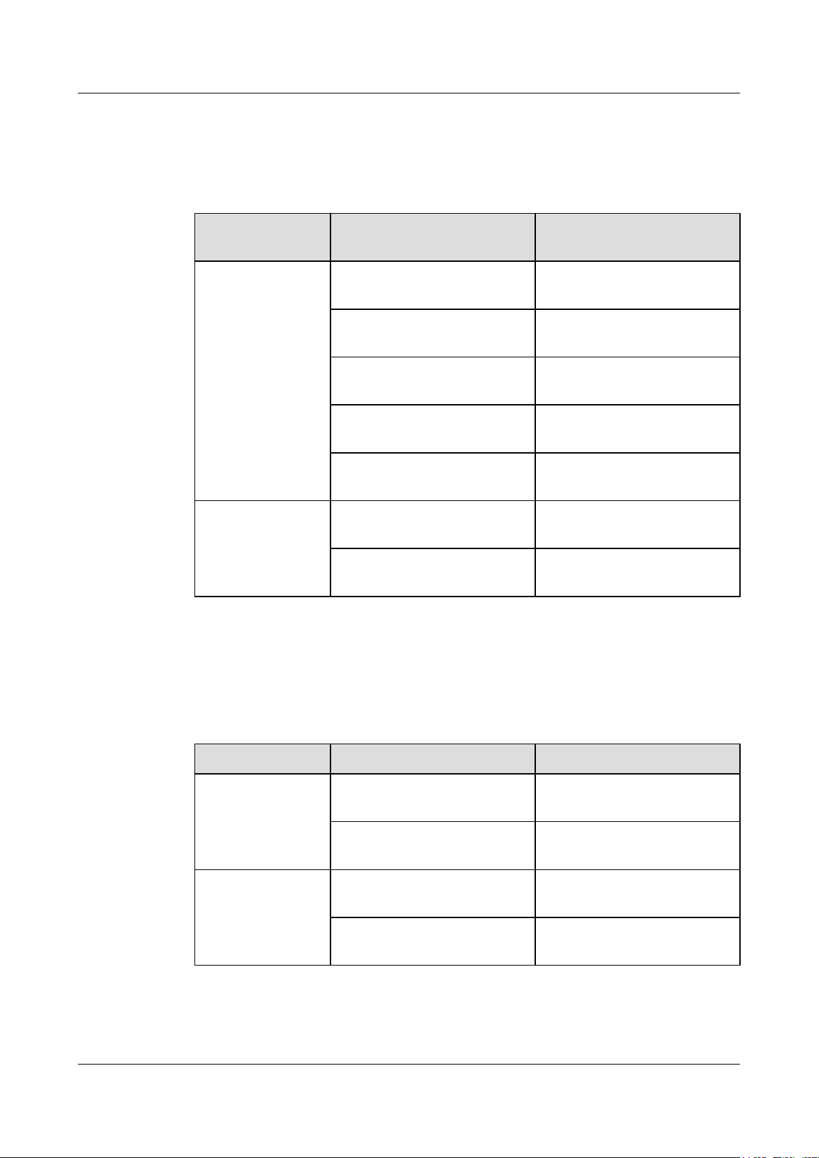
Table 1-5 lists the power modules available in V100R002C00.
Table 1-5 Power modules available in V100R002C00
1 Version Support for Components
Power Module
Power Module Power Description
Type
AC power module PAC-150WA 150 W AC power module
(natural heat dissipation)
PAC-350WA-B 350 W AC power module (air
exhaust on front panel)
PAC-350WA-F 350 W AC power module (air
intake on front panel)
PAC-600WA-B
*
600 W AC power module (air
exhaust on front panel)
PAC-600WA-F
*
600 W AC power module (air
intake on front panel)
DC power module
PDC-350WA-B
*
350 W DC power module (air
exhaust on front panel)
PDC-350WA-F
*
350 W DC power module (air
intake on front panel)
Available Fan Modules
Table 1-6 lists the fan modules available in V100R002C00.
Table 1-6 Fan modules available in V100R002C00
Series Model Description
FAN-40EA FAN-40EA-B FAN-40EA (air exhaust on front
FAN-40SB
panel)
FAN-40EA-F FAN-40EA (air intake on front
panel)
FAN-40SB-B
*
FAN-40SB (air exhaust on front
panel)
FAN-40SB-F
*
FAN-40SB (air intake on front
panel)
Issue 16 (2015-08-26) Huawei Proprietary and Confidential
Copyright © Huawei Technologies Co., Ltd.
4
Page 15
CloudEngine 7800&6800&5800 Series Switches
Hardware Description
1 Version Support for Components
1.3 Components Available in V100R003C00
NOTE
The components marked * are the new components added to V100R003C00.
Available Models
Table 1-7 lists the switch models available in V100R003C00.
Table 1-7 Models available in V100R003C00
Series Model Maximum Number of Ports Supported and Port
Description
CE7800
CE7850-32Q-EI
*
32 total:
32 40GE QSFP+ optical ports (can be split into four
10GE ports)
CE6800
CE6810-48S4Q-EI
*
52 total:
48 10GE SFP+ optical ports, 4 40GE QSFP+ optical
ports (can be split into four 10GE ports)
CE6850-48S4Q-EI 52 total:
48 10GE SFP+ optical ports, 4 40GE QSFP+ optical
ports (can be split into four 10GE ports)
CE6850-48T4Q-EI 52 total:
48 10GBASE-T Ethernet electrical ports, 4 40GE
QSFP+ optical ports (can be split into four 10GE
ports)
CE5800 CE5810-24T4S-EI 28 total:
24 10/100/1000BASE-T Ethernet electrical ports, 4
10GE SFP+ optical ports
CE5810-48T4S-EI 52 total:
48 10/100/1000BASE-T Ethernet electrical ports, 4
10GE SFP+ optical ports
CE5850-48T4S2Q-EI54 total:
48 10/100/1000BASE-T Ethernet electrical ports, 4
10GE SFP+ optical ports, 2 40GE QSFP+ optical ports
(cannot be split into four 10GE ports)
CE5850-48T4S2Q-
*
HI
54 total:
48 10/100/1000BASE-T Ethernet electrical ports, 4
10GE SFP+ optical ports, 2 40GE QSFP+ optical ports
(can be split into four 10GE ports)
Issue 16 (2015-08-26) Huawei Proprietary and Confidential
Copyright © Huawei Technologies Co., Ltd.
5
Page 16
CloudEngine 7800&6800&5800 Series Switches
Hardware Description 1 Version Support for Components
Available Power Modules
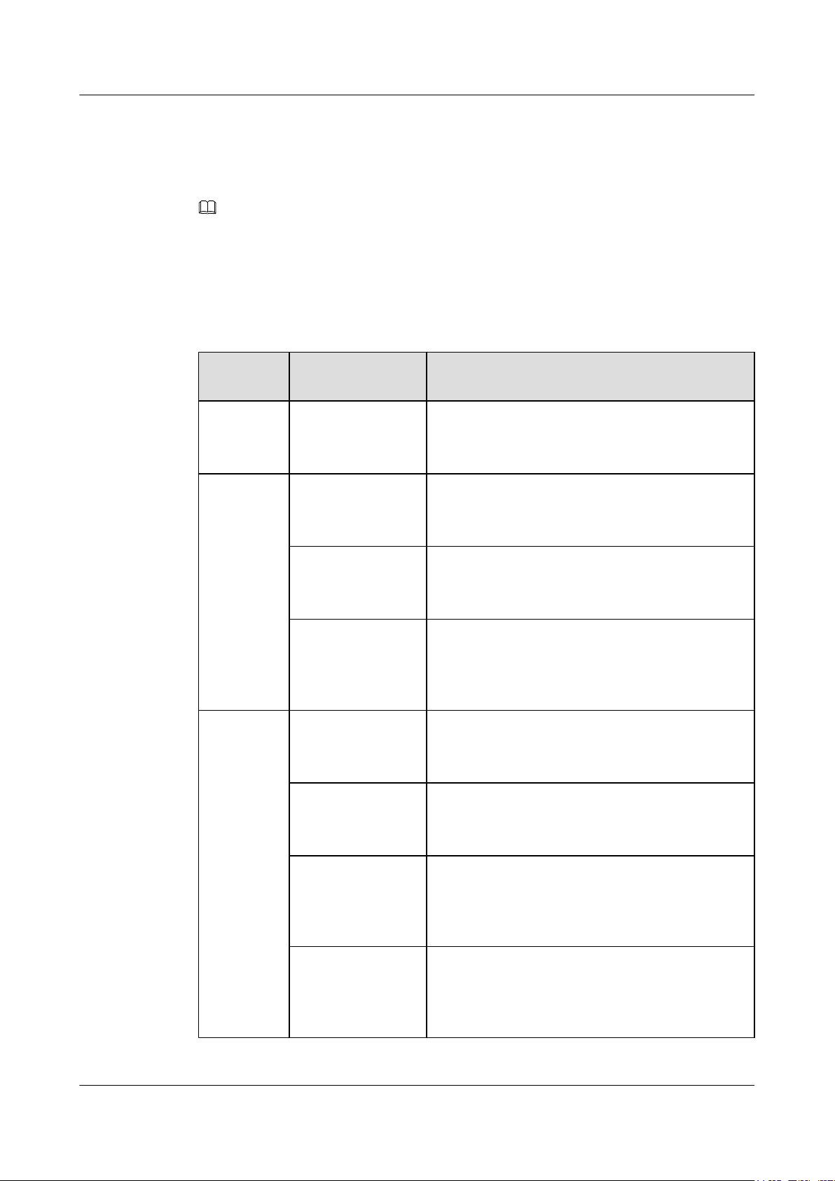
Table 1-8 lists the power modules available in V100R003C00.
Table 1-8 Power modules available in V100R003C00
Power Module
Power Module Power Description
Type
AC power module PAC-150WA 150 W AC power module
(natural heat dissipation)
PAC-350WA-B 350 W AC power module (air
exhaust on front panel)
PAC-350WA-F 350 W AC power module (air
intake on front panel)
PAC-600WA-B 600 W AC power module (air
exhaust on front panel)
PAC-600WA-F 600 W AC power module (air
intake on front panel)
DC power module PDC-350WA-B 350 W DC power module (air
exhaust on front panel)
PDC-350WA-F 350 W DC power module (air
intake on front panel)
Available Fan Modules
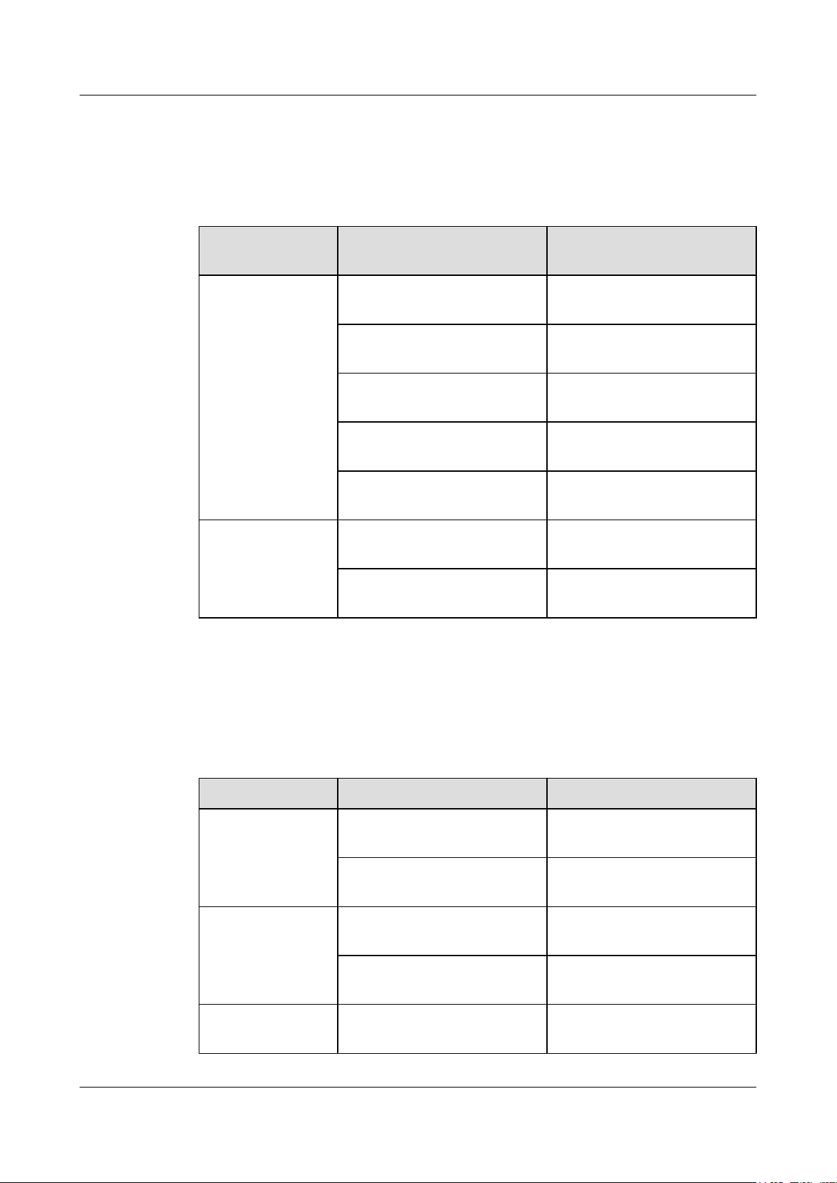
Table 1-9 lists the fan modules available in V100R003C00.
Table 1-9 Fan modules available in V100R003C00
Series Model Description
FAN-40EA FAN-40EA-B FAN-40EA (air exhaust on front
FAN-40SB FAN-40SB-B FAN-40SB (air exhaust on front
FAN-40HA
panel)
FAN-40EA-F FAN-40EA (air intake on front
panel)
panel)
FAN-40SB-F FAN-40SB (air intake on front
panel)
FAN-40HA-B
*
FAN-40HA (air exhaust on front
panel)
Issue 16 (2015-08-26) Huawei Proprietary and Confidential
Copyright © Huawei Technologies Co., Ltd.
6
Page 17
CloudEngine 7800&6800&5800 Series Switches
Hardware Description 1 Version Support for Components
Series Model Description
FAN-40HA-F
*
FAN-40HA (air intake on front
panel)
1.4 Components Available in V100R003C10
NOTE
The components marked * are the new components added to V100R003C10.
Available Models
Table 1-10 lists the switch models available in V100R003C10.
Table 1-10 Models available in V100R003C10
Series Model Maximum Number of Ports Supported and Port
Description
CE7800 CE7850-32Q-EI 32 total:
32 40GE QSFP+ optical ports (can be split into four
10GE ports)
CE6800 CE6810-48S4Q-EI 52 total:
48 10GE SFP+ optical ports, 4 40GE QSFP+ optical
ports (can be split into four 10GE ports)
CE6850-48S4Q-EI 52 total:
48 10GE SFP+ optical ports, 4 40GE QSFP+ optical
ports (can be split into four 10GE ports)
CE6850-48T4Q-EI 52 total:
48 10GBASE-T Ethernet electrical ports, 4 40GE
QSFP+ optical ports (can be split into four 10GE
ports)
*
CE6810-48S4Q-LI
52 total:
48 10GE SFP+ optical ports, 4 40GE QSFP+ optical
ports (can be split into four 10GE ports)
CE6810-48S-LI
*
48 total:
48 10GE SFP+ optical ports
CE5800 CE5810-24T4S-EI 28 total:
24 10/100/1000BASE-T Ethernet electrical ports, 4
10GE SFP+ optical ports
Issue 16 (2015-08-26) Huawei Proprietary and Confidential
Copyright © Huawei Technologies Co., Ltd.
7
Page 18
CloudEngine 7800&6800&5800 Series Switches
Hardware Description
Series Model Maximum Number of Ports Supported and Port
CE5810-48T4S-EI 52 total:
CE5850-48T4S2Q-EI54 total:
CE5850-48T4S2Q-HI54 total:
1 Version Support for Components
Description
48 10/100/1000BASE-T Ethernet electrical ports, 4
10GE SFP+ optical ports
48 10/100/1000BASE-T Ethernet electrical ports, 4
10GE SFP+ optical ports, 2 40GE QSFP+ optical ports
(cannot be split into four 10GE ports)
48 10/100/1000BASE-T Ethernet electrical ports, 4
10GE SFP+ optical ports, 2 40GE QSFP+ optical ports
(can be split into four 10GE ports)
Available Power Modules
Table 1-11 lists the power modules available in V100R003C10.
Table 1-11 Power modules available in V100R003C10
Power Module
Type
AC power module PAC-150WA 150 W AC power module
DC power module PDC-350WA-B 350 W DC power module (air
Power Module Power Description
(natural heat dissipation)
PAC-350WA-B 350 W AC power module (air
exhaust on front panel)
PAC-350WA-F 350 W AC power module (air
intake on front panel)
PAC-600WA-B 600 W AC power module (air
exhaust on front panel)
PAC-600WA-F 600 W AC power module (air
intake on front panel)
exhaust on front panel)
PDC-350WA-F 350 W DC power module (air
Available Fan Modules
Table 1-12 lists the fan modules available in V100R003C10.
Issue 16 (2015-08-26) Huawei Proprietary and Confidential
Copyright © Huawei Technologies Co., Ltd.
intake on front panel)
8
Page 19
CloudEngine 7800&6800&5800 Series Switches
Hardware Description 1 Version Support for Components
Table 1-12 Fan modules available in V100R003C10
Series Model Description
FAN-40EA FAN-40EA-B FAN-40EA (air exhaust on front
panel)
FAN-40EA-F FAN-40EA (air intake on front
panel)
FAN-40SB FAN-40SB-B FAN-40SB (air exhaust on front
panel)
FAN-40SB-F FAN-40SB (air intake on front
panel)
FAN-40HA FAN-40HA-B FAN-40HA (air exhaust on front
panel)
FAN-40HA-F FAN-40HA (air intake on front
panel)
1.5 Components Available in V100R005C00
NOTE
The components marked * are the new components added to V100R005C00.
Available Models
Table 1-13 lists the switch models available in V100R005C00.
Table 1-13 Models available in V100R005C00
Series Model Maximum Number of Ports Supported and Port
Description
CE7800 CE7850-32Q-EI 32 total:
32 40GE QSFP+ optical ports (can be split into four
10GE ports)
CE6800 CE6810-48S4Q-EI 52 total:
48 10GE SFP+ optical ports, 4 40GE QSFP+ optical
ports (can be split into four 10GE ports)
CE6850-48S4Q-EI 52 total:
48 10GE SFP+ optical ports, 4 40GE QSFP+ optical
ports (can be split into four 10GE ports)
Issue 16 (2015-08-26) Huawei Proprietary and Confidential
Copyright © Huawei Technologies Co., Ltd.
9
Page 20
CloudEngine 7800&6800&5800 Series Switches
Hardware Description 1 Version Support for Components
Series Model Maximum Number of Ports Supported and Port
Description
CE6850-48T4Q-EI 52 total:
48 10GBASE-T Ethernet electrical ports, 4 40GE
QSFP+ optical ports (can be split into four 10GE
ports)
CE6810-48S4Q-LI 52 total:
48 10GE SFP+ optical ports, 4 40GE QSFP+ optical
ports (can be split into four 10GE ports)
CE6810-48S-LI 48 total:
48 10GE SFP+ optical ports
*
CE6850-48S6Q-HI
54 total:
48 10GE SFP+ optical ports, 6 40GE QSFP+ optical
ports (can be split into four 10GE ports)
CE5800 CE5810-24T4S-EI 28 total:
Available Power Modules
Table 1-14 lists the power modules available in V100R005C00.
24 10/100/1000BASE-T Ethernet electrical ports, 4
10GE SFP+ optical ports
CE5810-48T4S-EI 52 total:
48 10/100/1000BASE-T Ethernet electrical ports, 4
10GE SFP+ optical ports
CE5850-48T4S2Q-EI54 total:
48 10/100/1000BASE-T Ethernet electrical ports, 4
10GE SFP+ optical ports, 2 40GE QSFP+ optical ports
(cannot be split into four 10GE ports)
CE5850-48T4S2Q-HI54 total:
48 10/100/1000BASE-T Ethernet electrical ports, 4
10GE SFP+ optical ports, 2 40GE QSFP+ optical ports
(can be split into four 10GE ports)
Table 1-14 Power modules available in V100R005C00
Power Module
Power Module Power Description
Type
AC power module PAC-150WA 150 W AC power module
Issue 16 (2015-08-26) Huawei Proprietary and Confidential
Copyright © Huawei Technologies Co., Ltd.
(natural heat dissipation)
10
Page 21
CloudEngine 7800&6800&5800 Series Switches
Hardware Description 1 Version Support for Components
Power Module
Power Module Power Description
Type
PAC-350WA-B 350 W AC power module (air
exhaust on front panel)
PAC-350WA-F 350 W AC power module (air
intake on front panel)
PAC-600WA-B 600 W AC power module (air
exhaust on front panel)
PAC-600WA-F 600 W AC power module (air
intake on front panel)
PAC-600WB-B
*
600 W AC&240 V DC power
module (air exhaust on front
panel)
PAC-600WB-F
*
600 W AC&240 V DC power
module (air intake on front panel)
DC power module PDC-350WA-B 350 W DC power module (air
exhaust on front panel)
High-voltage DC
power module
Available Fan Modules
Table 1-15 lists the fan modules available in V100R005C00.
Table 1-15 Fan modules available in V100R005C00
Series Model Description
FAN-40EA FAN-40EA-B FAN-40EA series fan modules
PDC-350WA-F 350 W DC power module (air
intake on front panel)
PHD-600WA-B
*
600 W high-voltage DC power
module (air exhaust on front
panel)
PHD-600WA-F
*
600 W high-voltage DC power
module (air intake on front panel)
(air exhaust on front panel)
FAN-40EA-F FAN-40EA series fan modules
(air intake on front panel)
FAN-40SB FAN-40SB-B FAN-40SB series fan modules
Issue 16 (2015-08-26) Huawei Proprietary and Confidential
Copyright © Huawei Technologies Co., Ltd.
(air exhaust on front panel)
11
Page 22
CloudEngine 7800&6800&5800 Series Switches
Hardware Description 1 Version Support for Components
Series Model Description
FAN-40SB-F FAN-40SB series fan modules
(air intake on front panel)
FAN-40HA FAN-40HA-B FAN-40HA series fan modules
(air exhaust on front panel)
FAN-40HA-F FAN-40HA series fan modules
(air intake on front panel)
FAN-060A
FAN-060A-B
*
FAN-060A series fan modules
(air exhaust on front panel)
FAN-060A-F
*
FAN-060A series fan modules
(air intake on front panel)
1.6 Components Available in V100R005C10
NOTE
The components marked * are the new components added to V100R005C10.
Available Models
Table 1-16 lists the switch models available in V100R005C10.
Table 1-16 Models available in V100R005C10
Series Model Maximum Number of Ports Supported and Port
Description
CE7800 CE7850-32Q-EI 32 total:
32 40GE QSFP+ optical ports (can be split into four
10GE ports)
CE6800 CE6810-48S4Q-EI 52 total:
48 10GE SFP+ optical ports, 4 40GE QSFP+ optical
ports (can be split into four 10GE ports)
CE6850-48S4Q-EI 52 total:
48 10GE SFP+ optical ports, 4 40GE QSFP+ optical
ports (can be split into four 10GE ports)
CE6850-48T4Q-EI 52 total:
48 10GBASE-T Ethernet electrical ports, 4 40GE
QSFP+ optical ports (can be split into four 10GE
ports)
Issue 16 (2015-08-26) Huawei Proprietary and Confidential
Copyright © Huawei Technologies Co., Ltd.
12
Page 23
CloudEngine 7800&6800&5800 Series Switches
Hardware Description 1 Version Support for Components
Series Model Maximum Number of Ports Supported and Port
Description
CE6810-48S4Q-LI 52 total:
48 10GE SFP+ optical ports, 4 40GE QSFP+ optical
ports (can be split into four 10GE ports)
CE6810-48S-LI 48 total:
48 10GE SFP+ optical ports
CE6850-48S6Q-HI 54 total:
48 10GE SFP+ optical ports, 6 40GE QSFP+ optical
ports (can be split into four 10GE ports)
*
CE6851-48S6Q-HI
54 total:
48 10GE SFP+ optical ports, 6 40GE QSFP+ optical
ports (can be split into four 10GE ports)
CE6850U-48S6Q-
*
HI
54 total:
48 10GE SFP+/FC optical ports, 6 40GE QSFP+
optical ports (can be split into four 10GE ports)
*
CE6850-48T6Q-HI
54 total:
48 10GBASE-T Ethernet electrical ports, 6 40GE
QSFP+ optical ports (can be split into four 10GE
ports)
CE6850U-24S2Q-
*
HI
26 total:
24 10GE SFP+/FC optical ports, 2 40GE QSFP+
optical ports (can be split into four 10GE ports)
CE6810-32T16S4Q
*
-LI
52 total:
32 10GBASE-T Ethernet electrical ports, 16 10GE
SFP+ optical ports, 4 40GE QSFP+ optical ports (can
be split into four 10GE ports)
*
CE6810-24S2Q-LI
26 total:
24 10GE SFP+ optical ports, 2 40GE QSFP+ optical
ports (can be split into four 10GE ports)
CE5800 CE5810-24T4S-EI 28 total:
24 10/100/1000BASE-T Ethernet electrical ports, 4
10GE SFP+ optical ports
CE5810-48T4S-EI 52 total:
48 10/100/1000BASE-T Ethernet electrical ports, 4
10GE SFP+ optical ports
Issue 16 (2015-08-26) Huawei Proprietary and Confidential
Copyright © Huawei Technologies Co., Ltd.
13
Page 24
CloudEngine 7800&6800&5800 Series Switches
Hardware Description 1 Version Support for Components
Series Model Maximum Number of Ports Supported and Port
Description
CE5850-48T4S2Q-EI54 total:
48 10/100/1000BASE-T Ethernet electrical ports, 4
10GE SFP+ optical ports, 2 40GE QSFP+ optical ports
(cannot be split into four 10GE ports)
CE5850-48T4S2Q-HI54 total:
48 10/100/1000BASE-T Ethernet electrical ports, 4
10GE SFP+ optical ports, 2 40GE QSFP+ optical ports
(can be split into four 10GE ports)
Available Power Modules
Table 1-17 lists the power modules available in V100R005C10.
Table 1-17 Power modules available in V100R005C10
Power Module
Type
AC power module PAC-150WA 150 W AC power module
CE5855-48T4S2Q-
*
EI
CE5855-24T4S2Q-
*
EI
Power Module Power Description
54 total:
48 10/100/1000BASE-T Ethernet electrical ports, 4
10GE SFP+ optical ports, 2 40GE QSFP+ optical ports
(can be split into four 10GE ports)
30 total:
24 10/100/1000BASE-T Ethernet electrical ports, 4
10GE SFP+ optical ports, 2 40GE QSFP+ optical ports
(can be split into four 10GE ports)
(natural heat dissipation)
ES0W2PSA0150
*
PAC-350WA-B 350 W AC power module (air
PAC-350WA-F 350 W AC power module (air
PAC-600WA-B 600 W AC power module (air
PAC-600WA-F 600 W AC power module (air
Issue 16 (2015-08-26) Huawei Proprietary and Confidential
Copyright © Huawei Technologies Co., Ltd.
150 W AC power module
(natural heat dissipation)
exhaust on front panel)
intake on front panel)
exhaust on front panel)
intake on front panel)
14
Page 25
CloudEngine 7800&6800&5800 Series Switches
Hardware Description 1 Version Support for Components
Power Module
Type
DC power module PDC-350WA-B 350 W DC power module (air
High-voltage DC
power module
Power Module Power Description
PAC-600WB-B 600 W AC&240 V DC power
module (air exhaust on front
panel)
PAC-600WB-F 600 W AC&240 V DC power
module (air intake on front panel)
exhaust on front panel)
PDC-350WA-F 350 W DC power module (air
intake on front panel)
PHD-600WA-B 600 W high-voltage DC power
module (air exhaust on front
panel)
PHD-600WA-F 600 W high-voltage DC power
module (air intake on front panel)
Available Fan Modules
Table 1-18 lists the fan modules available in V100R005C10.
Table 1-18 Fan modules available in V100R005C10
Series Model Description
FAN-40EA FAN-40EA-B FAN-40EA series fan modules
FAN-40SB FAN-40SB-B FAN-40SB series fan modules
FAN-40HA FAN-40HA-B FAN-40HA series fan modules
(air exhaust on front panel)
FAN-40EA-F FAN-40EA series fan modules
(air intake on front panel)
(air exhaust on front panel)
FAN-40SB-F FAN-40SB series fan modules
(air intake on front panel)
(air exhaust on front panel)
FAN-40HA-F FAN-40HA series fan modules
(air intake on front panel)
FAN-060A FAN-060A-B FAN-060A series fan modules
Issue 16 (2015-08-26) Huawei Proprietary and Confidential
Copyright © Huawei Technologies Co., Ltd.
(air exhaust on front panel)
15
Page 26

CloudEngine 7800&6800&5800 Series Switches
Hardware Description 1 Version Support for Components
Series Model Description
FAN-060A-F FAN-060A series fan modules
(air intake on front panel)
FAN-040A
FAN-040A-B
FAN-040A-F
*
FAN-040A series fan modules
(air exhaust on front panel)
*
FAN-040A series fan modules
(air intake on front panel)
Issue 16 (2015-08-26) Huawei Proprietary and Confidential
Copyright © Huawei Technologies Co., Ltd.
16
Page 27

CloudEngine 7800&6800&5800 Series Switches
Hardware Description 2 Chassis
2 Chassis
About This Chapter
2.1 Naming Conventions
2.2 Version Mapping
2.3 Appearance and Structure
2.4 Indicators
2.5 Ports
2.6 Specifications
2.7 Ordering Information
Issue 16 (2015-08-26) Huawei Proprietary and Confidential
Copyright © Huawei Technologies Co., Ltd.
17
Page 28
A B C D E F
CE6850U-48S6Q-EI
CloudEngine 7800&6800&5800 Series Switches
Hardware Description 2 Chassis
2.1 Naming Conventions
Figure 2-1 shows the CE7800&6800&5800 series switches naming conventions.
Figure 2-1 CE7800&6800&5800 series switches naming conventions
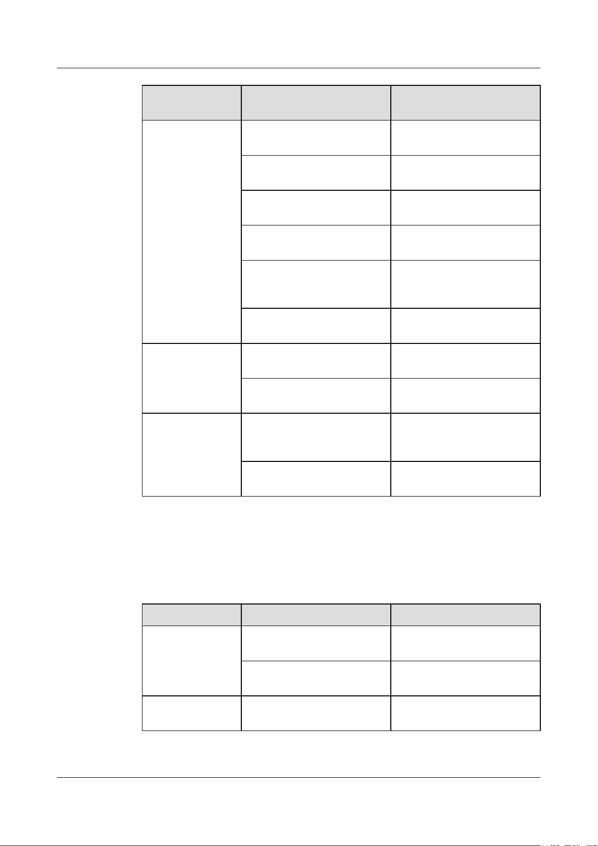
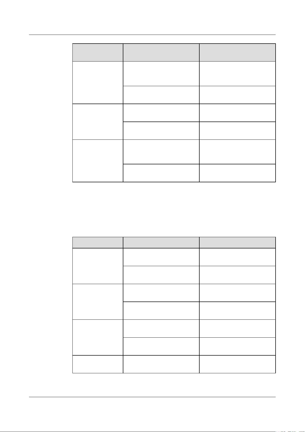
Table 2-1 describes the CE7800&6800&5800 series switches naming conventions.
Table 2-1 CE7800&6800&5800 series switches naming conventions
FieldMeaning
A CloudEngine series data center switches
l CE78: CE7800 series
l CE68: CE6800 series
l CE58: CE5800 series
B Product model category:
l 10: basic model
l 50: advanced model
C Special function flag. This flag is not present if the product does not provide special
functions.
U: The product supports the unified port function.
D Number and type of downlink interfaces:
l T: GE/10GBase-T electrical interfaces
l S: GE/10GE SFP+ optical interfaces
l Q: quad small form-factor pluggable plus (QSFP+) optical interfaces
E Number and types of uplink interfaces:
l T: GE/10GBase-T electrical interfaces
l S: GE/10GE SFP+ optical interfaces
l Q: QSFP+ optical interfaces
NOTE
This field is not present in the product name if the product has only fixed interfaces and the uplink
and downlink interfaces are the same type or if the product supports flexible service units.
Issue 16 (2015-08-26) Huawei Proprietary and Confidential
Copyright © Huawei Technologies Co., Ltd.
18
Page 29
CloudEngine 7800&6800&5800 Series Switches
Hardware Description 2 Chassis
FieldMeaning
F Product model type:
l LI: model providing basic functions
l EI: model providing enhanced functions
l HI: model providing advanced functions
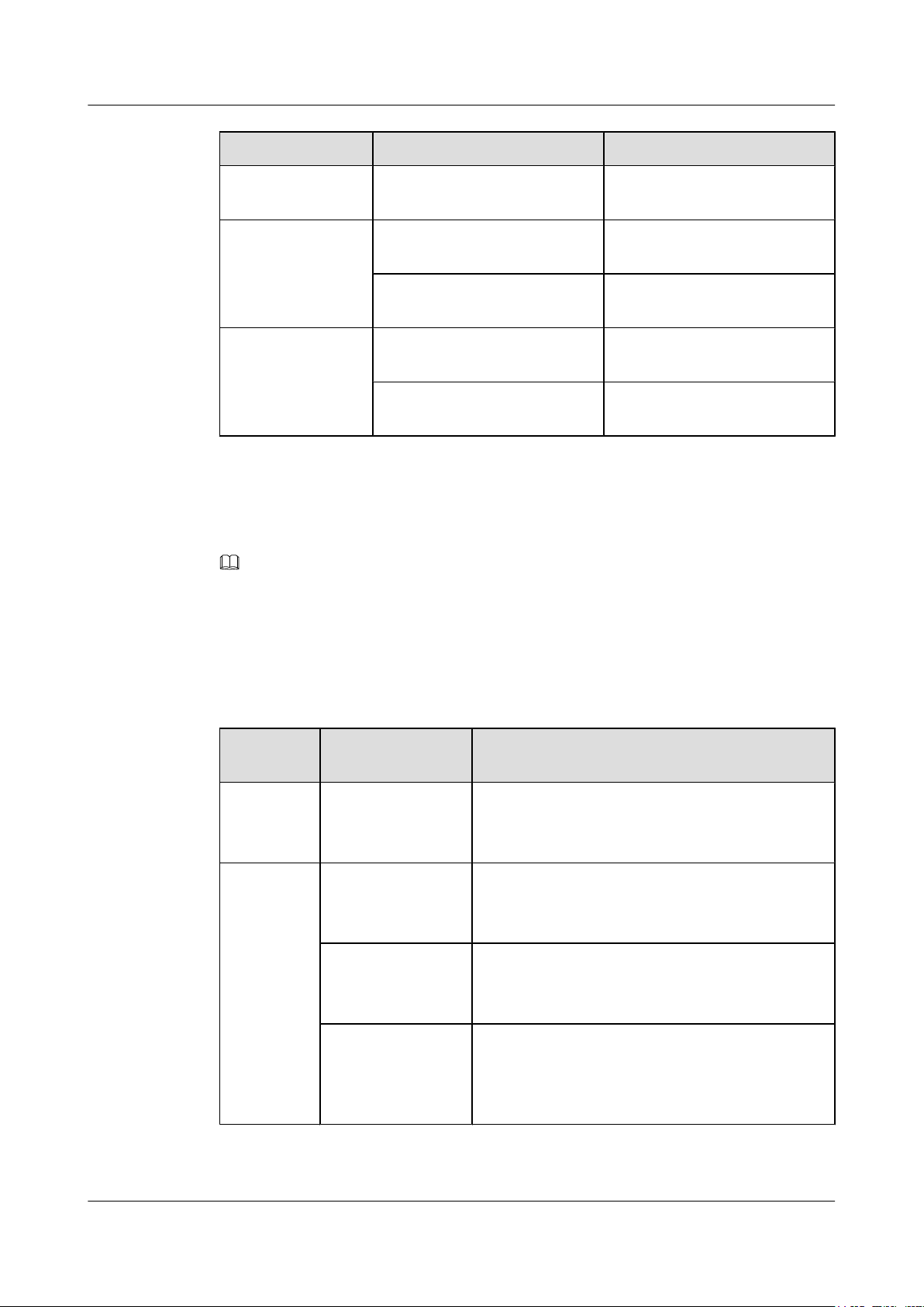
2.2 Version Mapping
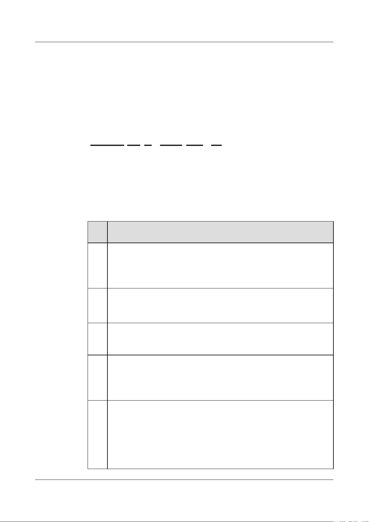
Table 2-2 lists the mapping between the CE7800&6800&5800 series switches and software
versions.
Table 2-2 Mapping between the CE7800&6800&5800 series switches and software versions
Series Model Available Version
CE7800 CE7850 CE7850-32Q-EI V100R003C00 and later versions
CE6800 CE6810 CE6810-48S4Q-EI V100R003C00 and later versions
CE6810-48S4Q-LI V100R003C10 and later versions
CE6810-48S-LI V100R003C10 and later versions
CE6810-32T16S4Q-LIV100R005C10 and later versions
CE6810-24S2Q-LI V100R005C10 and later versions
CE6850 CE6850-48S4Q-EI V100R001C00 and later versions
CE6850-48T4Q-EI V100R001C00 and later versions
CE6850-48S6Q-HI V100R005C00 and later versions
CE6850-48T6Q-HI V100R005C10 and later versions
CE6851-48S6Q-HI V100R005C10 and later versions
CE6850U-48S6Q-HI V100R005C10 and later versions
CE6850U-24S2Q-HI V100R005C10 and later versions
CE5800 CE5810 CE5810-24T4S-EI V100R002C00 and later versions
CE5810-48T4S-EI V100R002C00 and later versions
CE5850 CE5850-48T4S2Q-EI V100R001C00 and later versions
CE5850-48T4S2Q-HI V100R003C00 and later versions
CE5855 CE5855-48T4S2Q-EI V100R005C10 and later versions
Issue 16 (2015-08-26) Huawei Proprietary and Confidential
Copyright © Huawei Technologies Co., Ltd.
19
Page 30
12 34 56 78 910 11 12 13 14 15 16 17 18 19 20 21 22 23 24 25 26 27 28 29 30 31 32
SYS
MST
STAT
SPEED
STACK
MODE/ID
CE7850-32Q-EI
4321
40GE
Breakout
CONSOLE
ETH
SYS
MST
ACT
L/A
ID
PWR1 FAN1 FAN2 PWR2
CE7850-32Q-EI
STATUS
STATUS
STATUS
STATUS
9
1
2345678
1010
1111 1212
12 12 13
1010
Front (power supply side)
Rear (port side)
Left side
Right side
11 11
CloudEngine 7800&6800&5800 Series Switches
Hardware Description 2 Chassis
Series Model Available Version
CE5855-24T4S2Q-EI V100R005C10 and later versions
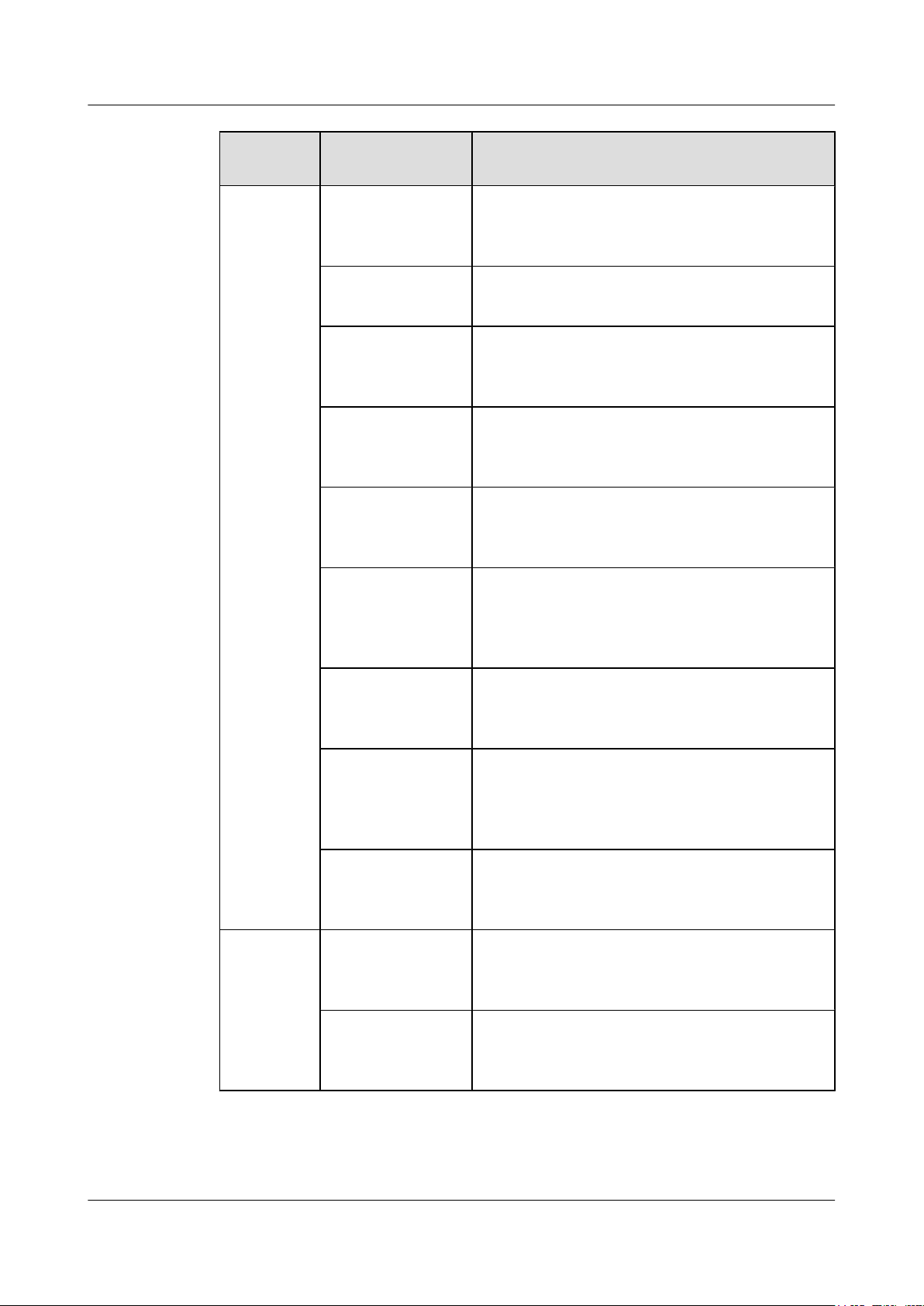
2.3 Appearance and Structure
NOTE
The figures in this document are for reference only.
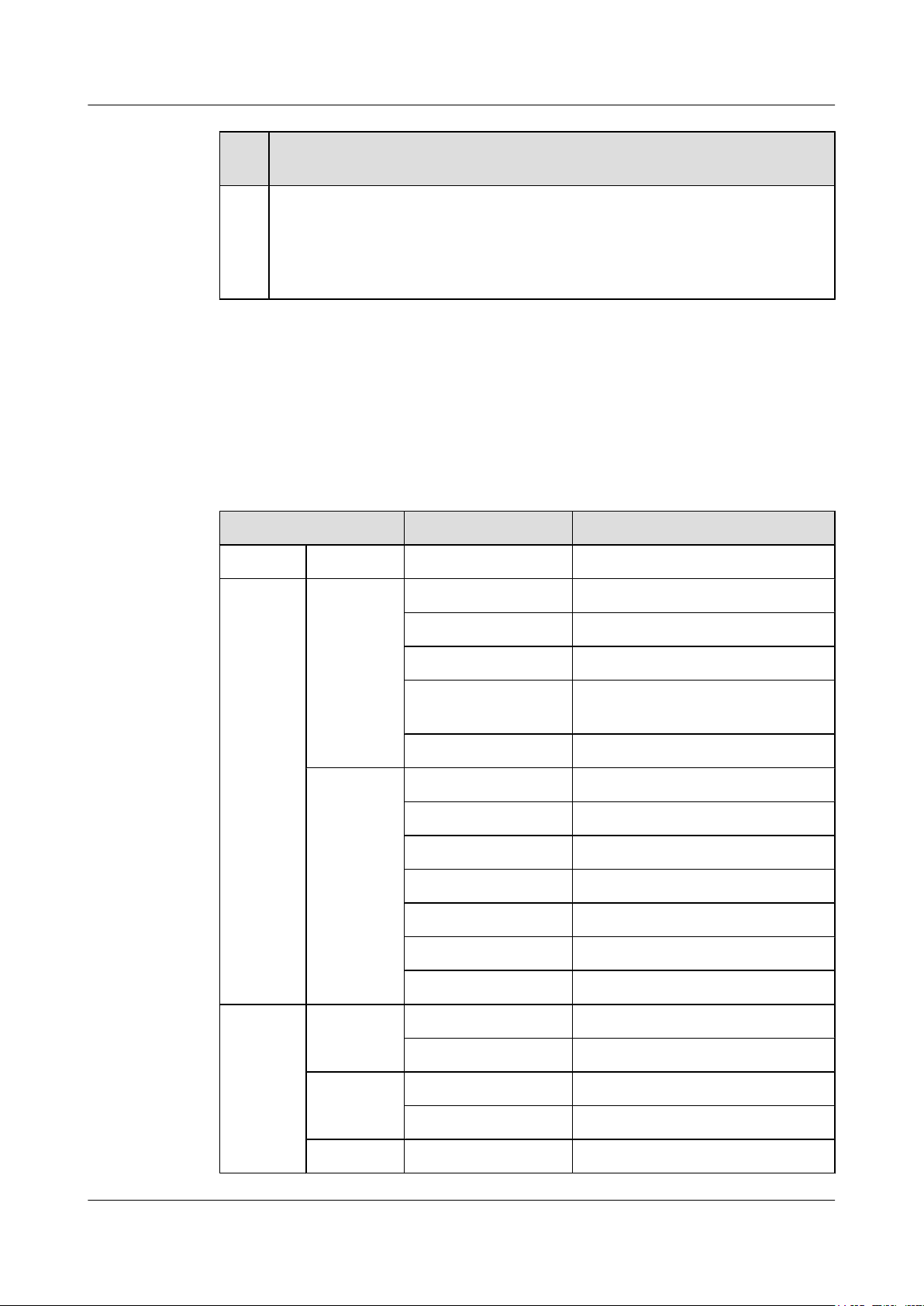
CE7850-32Q-EI
Figure 2-2 Appearance of the CE7850-32Q-EI
Power supply slot 1
1
Applicable power modules:
l 600 W AC power module
3 Fan slot 1
Applicable fan modules:
l FAN-40HA series fan modules
5 Console port 6 ETH management port (RJ45)
Issue 16 (2015-08-26) Huawei Proprietary and Confidential
Copyright © Huawei Technologies Co., Ltd.
2 Power supply slot 2
Applicable power modules:
l 600 W AC power module
4 Fan slot 2
Applicable fan modules:
l FAN-40HA series fan modules
20
Page 31

CloudEngine 7800&6800&5800 Series Switches
Hardware Description 2 Chassis
7
Barcode label
NOTE
This label is drawable, and you can pull it
outward to view the barcode and MAC address
of the switch.
9 Thirty-two 40GE QSFP+ Ethernet
optical ports
NOTE
A 40GE QSFP+ port can be split into four
10GE ports.
Applicable modules and cables:
l 40GE optical module
l 10 m QSFP+ AOC cable (QSFP+ to
QSFP+)
l 1 m, 3 m, 5 m QSFP+ copper cables
(QSFP+ to 4*SFP+)
l 1 m, 3 m, 5 m QSFP+ copper cables
(QSFP+ to QSFP+)
11 Four middle mounting holes for mounting
brackets
8
USB port
Three port-side mounting holes for
10
mounting brackets
12 Four power-supply-side mounting holes
for mounting brackets
13 Ground screw - -
Issue 16 (2015-08-26) Huawei Proprietary and Confidential
Copyright © Huawei Technologies Co., Ltd.
21
Page 32

12 3413 14 15 16 17 18 19 20 21 22 23 24 25 26 27 28 29 30 31 32 33 34 35 36 37 38 39 40 41 42 43 44 45 46 47 481234567891011 12
SYS
MST
STAT
SPEED
STACK
MODE/ID
CE6810-48S4Q-EI
4321
40GE
Breakout
CONSOLE
ETH
SYS
MST
ACT
L/A
ID
PWR1 FAN1 FAN2 PWR2
CE6810-48S4Q-EI
STATUS
STATUS
STATUS
STATUS
9
1
2345678
1111
1212 1313
13 13 14
1111
Front (power supply side)
Rear (port side)
Left side
Right side
12 12
10
CloudEngine 7800&6800&5800 Series Switches
Hardware Description 2 Chassis
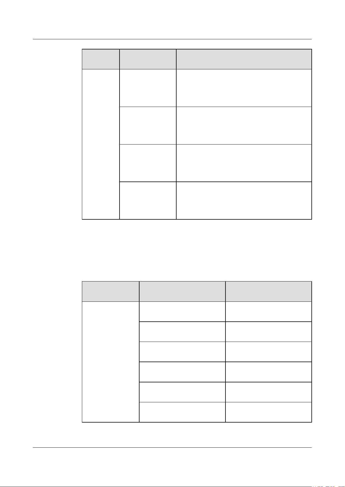
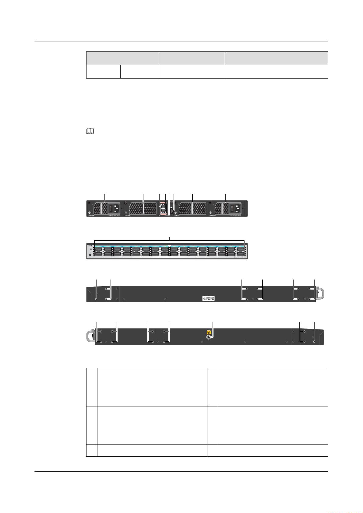
CE6810-48S4Q-EI
Figure 2-3 Appearance of the CE6810-48S4Q-EI
1 Power supply slot 1
Applicable power modules:
l 350 W DC power module
l 600 W AC power module
3 Fan slot 1
Applicable fan modules:
l FAN-40EA series fan modules
5 Console port 6 ETH management port (RJ45)
7
Barcode label
NOTE
2 Power supply slot 2
Applicable power modules:
l 350 W DC power module
l 600 W AC power module
4 Fan slot 2
Applicable fan modules:
l FAN-40EA series fan modules
8
USB port
This label is drawable, and you can pull it
outward to view the barcode and MAC address
of the switch.
Issue 16 (2015-08-26) Huawei Proprietary and Confidential
Copyright © Huawei Technologies Co., Ltd.
22
Page 33

12 3413 14 15 16 17 18 19 20 21 22 23 24 25 26 27 28 29 30 31 32 33 34 35 36 37 38 39 40 41 42 43 44 45 46 47 481234567891011 12
SYS
MST
STAT
SPEED
STACK
MODE/ID
CE6810-48S4Q-LI
4321
40GE
Breakout
CONSOLE
ETH
SYS
MST
ACT
L/A
ID
PWR1 FAN1 FAN2 PWR2
CE6810-48S4Q-LI
STATUS
STATUS
STATUS
STATUS
9
1
2345678
1111
1212 1313
13 13 14
1111
Front (power supply side)
Rear (port side)
Left side
Right side
12 12
10
CloudEngine 7800&6800&5800 Series Switches
Hardware Description 2 Chassis
9 Forty-eight 10GE SFP+ Ethernet
optical ports
Applicable modules and cables:
l 10GE optical module (OSXD22N00
and LE2MXSC80FF0 not supported)
l 10GE-CWDM optical module
l GE optical module
l GE-CWDM optical module
l GE copper module (works at 10 Mbit/
s, 100 Mbit/s, or 1000 Mbit/s)
l 3 m, 10 m, 20 m SFP+ AOC cables
l 1 m, 3 m, 5 m, 7 m (active), 10 m
(active) SFP+ copper cables
Three port-side mounting holes for
11
mounting brackets
13 Four power-supply-side mounting holes
for mounting brackets
Four 40GE QSFP+ Ethernet optical
10
ports
NOTE
A 40GE QSFP+ port can be split into four
10GE ports.
Applicable modules and cables:
l 40GE optical module
l 10 m QSFP+ AOC cable (QSFP+ to
QSFP+)
l 1 m, 3 m, 5 m QSFP+ copper cables
(QSFP+ to 4*SFP+)
l 1 m, 3 m, 5 m QSFP+ copper cables
(QSFP+ to QSFP+)
12 Four middle mounting holes for mounting
brackets
14 Ground screw
CE6810-48S4Q-LI
Figure 2-4 Appearance of the CE6810-48S4Q-LI
Issue 16 (2015-08-26) Huawei Proprietary and Confidential
Copyright © Huawei Technologies Co., Ltd.
23
Page 34

CloudEngine 7800&6800&5800 Series Switches
Hardware Description 2 Chassis
1 Power supply slot 1
Applicable power modules:
l 350 W DC power module
l 600 W AC power module
3 Fan slot 1
Applicable fan modules:
l FAN-40EA series fan modules
2 Power supply slot 2
Applicable power modules:
l 350 W DC power module
l 600 W AC power module
4 Fan slot 2
Applicable fan modules:
l FAN-40EA series fan modules
5 Console port 6 ETH management port (RJ45)
7
Barcode label
NOTE
This label is drawable, and you can pull it
outward to view the barcode and MAC address
of the switch.
9 Forty-eight 10GE SFP+ Ethernet
optical ports
Applicable modules and cables:
l 10GE optical module (OSXD22N00
8
USB port
Four 40GE QSFP+ Ethernet optical
10
ports
NOTE
A 40GE QSFP+ port can be split into four
10GE ports.
and LE2MXSC80FF0 not supported)
l 10GE-CWDM optical module
l GE optical module
l GE-CWDM optical module
Applicable modules and cables:
l 40GE optical module
l 10 m QSFP+ AOC cable (QSFP+ to
QSFP+)
l GE copper module (works at 10 Mbit/
s, 100 Mbit/s, or 1000 Mbit/s)
l 3 m, 10 m, 20 m SFP+ AOC cables
l 1 m, 3 m, 5 m, 7 m (active), 10 m
(active) SFP+ copper cables
l 1 m, 3 m, 5 m QSFP+ copper cables
(QSFP+ to 4*SFP+)
l 1 m, 3 m, 5 m QSFP+ copper cables
(QSFP+ to QSFP+)
Three port-side mounting holes for
11
mounting brackets
13 Four power-supply-side mounting holes
12 Four middle mounting holes for mounting
brackets
14 Ground screw
for mounting brackets
Issue 16 (2015-08-26) Huawei Proprietary and Confidential
Copyright © Huawei Technologies Co., Ltd.
24
Page 35

13 14 15 16 17 18 19 20 21 22 23 24 25 26 27 28 29 30 31 32 33 34 35 36 37 38 39 40 41 42 43 44 45 46 47 481234567891011 12
SYS
MST
STAT
SPEED
STACK
MODE/ID
CE6810-48S-LI
CONSOLE
ETH
SYS
MST
ACT
L/A
ID
PWR1 FAN1 FAN2 PWR2
CE6810-48S-LI
STATUS
STATUS
STATUS
STATUS
9
1
2345678
1010
1111 1212
12 12 13
1010
Front (power supply side)
Rear (port side)
Left side
Right side
11 11
CloudEngine 7800&6800&5800 Series Switches
Hardware Description 2 Chassis
CE6810-48S-LI
Figure 2-5 Appearance of the CE6810-48S-LI
1 Power supply slot 1
Applicable power modules:
l 350 W DC power module
l 600 W AC power module
3 Fan slot 1
Applicable fan modules:
l FAN-40EA series fan modules
5 Console port 6 ETH management port (RJ45)
7
Barcode label
NOTE
2 Power supply slot 2
Applicable power modules:
l 350 W DC power module
l 600 W AC power module
4 Fan slot 2
Applicable fan modules:
l FAN-40EA series fan modules
8
USB port
This label is drawable, and you can pull it
outward to view the barcode and MAC address
of the switch.
Issue 16 (2015-08-26) Huawei Proprietary and Confidential
Copyright © Huawei Technologies Co., Ltd.
25
Page 36

1234567891011 12 13 14 15 16 17 18 19 20 21 22 23 24 25 26 27 28 29 30 31 32
SYS
MST
STAT
SPEED
STACK
MODE/ID
CE6810-32T16S4Q-LI
33 34 35 36 37 38 39 40 41 42 43 44 45 46 47 48 12 34
CONSOLE
ETH
SYS
MST
ACT
L/A
ID
PWR1 FAN1 FAN2 PWR2
CE6810-32T16S4Q-LI
STATUS
PAC-600WA-B
STATUS
PAC-600WA-B
STATUS STATUS
9 10 11
1
2345678
1212 1313
13 13 14 1212
Front (power supply side)
Rear (port side)
Left side
Right side
4321
40GE
Breakout
CloudEngine 7800&6800&5800 Series Switches
Hardware Description 2 Chassis
9 Forty-eight 10GE SFP+ Ethernet
optical ports
Applicable modules and cables:
l 10GE optical module (OSXD22N00
l 10GE-CWDM optical module
l GE optical module
l GE-CWDM optical module
l GE copper module (works at 10 Mbit/
l 3 m, 10 m, 20 m SFP+ AOC cables
l 1 m, 3 m, 5 m, 7 m (active), 10 m
11 Four middle mounting holes for mounting
brackets
13 Ground screw - -
CE6810-32T16S4Q-LI
and LE2MXSC80FF0 not supported)
s, 100 Mbit/s, or 1000 Mbit/s)
(active) SFP+ copper cables
Three port-side mounting holes for
10
mounting brackets
12 Four power-supply-side mounting holes
for mounting brackets
Figure 2-6 Appearance of the CE6810-32T16S4Q-LI
Issue 16 (2015-08-26) Huawei Proprietary and Confidential
Copyright © Huawei Technologies Co., Ltd.
26
Page 37

CloudEngine 7800&6800&5800 Series Switches
Hardware Description 2 Chassis
1 Power supply slot 1
Applicable power modules:
l 350 W DC power module
l 600 W AC power module
3 Fan slot 1
Applicable fan modules:
l FAN-40EA series fan modules
2 Power supply slot 2
Applicable power modules:
l 350 W DC power module
l 600 W AC power module
4 Fan slot 2
Applicable fan modules:
l FAN-40EA series fan modules
5 Console port 6 ETH management port (RJ45)
7
Barcode label
NOTE
This label is drawable, and you can pull it
outward to view the barcode and MAC address
of the switch.
9 Thirty-two 10GBASE-T Ethernet
electrical ports
8
USB port
10 Sixteen 10GE SFP+ Ethernet optical
ports
Applicable modules and cables:
Four 40GE QSFP+ Ethernet optical
11
ports
NOTE
A 40GE QSFP+ port can be split into four
10GE ports.
Applicable modules and cables:
l 40GE optical module
l 10 m QSFP+ AOC cable (QSFP+ to
QSFP+)
l 10GE optical module (OSXD22N00
and LE2MXSC80FF0 not supported)
l 10GE-CWDM optical module
l GE optical module
l GE-CWDM optical module
l GE copper module (works at 10 Mbit/
s, 100 Mbit/s, or 1000 Mbit/s)
l 3 m, 10 m, 20 m SFP+ AOC cables
l 1 m, 3 m, 5 m, 7 m (active), 10 m
(active) SFP+ copper cables
Three port-side mounting holes for
12
mounting brackets
l 1 m, 3 m, 5 m QSFP+ copper cables
(QSFP+ to 4*SFP+)
l 1 m, 3 m, 5 m QSFP+ copper cables
(QSFP+ to QSFP+)
Issue 16 (2015-08-26) Huawei Proprietary and Confidential
Copyright © Huawei Technologies Co., Ltd.
27
Page 38

34
13 14 15 16 17 18 19 20 21 22 23 241234567891011 12
SYS
MST
STAT
SPEED
STACK
MODE/ID
CE6810-24S2Q-LI
4321
40GE
Breakout
CONSOLE
ETH
SYS
MST
ACT
L/A
ID
PWR1 FAN1 FAN2 PWR2
CE6810-24S2Q-LI
STATUS
STATUS
9
12
345678
1111
1212 1313
13 13 14
1111
Front (power supply side)
Rear (port side)
Left side
Right side
12 12
10
STATUS
PAC-600WA-B
STATUS
PAC-600WA-B
CloudEngine 7800&6800&5800 Series Switches
Hardware Description 2 Chassis
13 Four power-supply-side mounting holes
CE6810-24S2Q-LI
Figure 2-7 Appearance of the CE6810-24S2Q-LI
14 Ground screw
for mounting brackets
1 Power supply slot 1
Applicable power modules:
l 350 W DC power module
l 600 W AC power module
3 Fan slot 1
Applicable fan modules:
l FAN-40EA series fan modules
2 Power supply slot 2
Applicable power modules:
l 350 W DC power module
l 600 W AC power module
4 Fan slot 2
Applicable fan modules:
l FAN-40EA series fan modules
5 Console port 6 ETH management port (RJ45)
7
Barcode label
NOTE
This label is drawable, and you can pull it
outward to view the barcode and MAC address
of the switch.
8
USB port
Issue 16 (2015-08-26) Huawei Proprietary and Confidential
Copyright © Huawei Technologies Co., Ltd.
28
Page 39

12 34
13 14 15 16 17 18 19 20 21 22 23 24 25 26 27 28 29 30 31 32 33 34 35 36 37 38 39 40 41 42 43 44 45 46 47 481234567891011 12
SYS
MST
STAT
SPEED
STACK
MODE/ID
CE6850-48S4Q-EI
4321
40GE
Breakout
CONSOLE
ETH
SYS
MST
ACT
L/A
ID
PWR1 FAN1 FAN2 PWR2
CE6850-48S4Q-EI
STATUS
STATUS
STATUS
STATUS
9
1
2345678
1111
1212 1313
13 13 14
1111
Front (power supply side)
Rear (port side)
Left side
Right side
12 12
10
CloudEngine 7800&6800&5800 Series Switches
Hardware Description 2 Chassis
9 Twenty-four 10GE SFP+ Ethernet
optical ports
Applicable modules and cables:
l 10GE optical module (OSXD22N00
and LE2MXSC80FF0 not supported)
l 10GE-CWDM optical module
l GE optical module
l GE-CWDM optical module
l GE copper module (works at 10 Mbit/
s, 100 Mbit/s, or 1000 Mbit/s)
l 3 m, 10 m, 20 m SFP+ AOC cables
l 1 m, 3 m, 5 m, 7 m (active), 10 m
(active) SFP+ copper cables
Three port-side mounting holes for
11
mounting brackets
13 Four power-supply-side mounting holes
for mounting brackets
Two 40GE QSFP+ Ethernet optical
10
ports
NOTE
A 40GE QSFP+ port can be split into four
10GE ports.
Applicable modules and cables:
l 40GE optical module
l 10 m QSFP+ AOC cable (QSFP+ to
QSFP+)
l 1 m, 3 m, 5 m QSFP+ copper cables
(QSFP+ to 4*SFP+)
l 1 m, 3 m, 5 m QSFP+ copper cables
(QSFP+ to QSFP+)
12 Four middle mounting holes for mounting
brackets
14 Ground screw
CE6850-48S4Q-EI
Figure 2-8 Appearance of the CE6850-48S4Q-EI
Issue 16 (2015-08-26) Huawei Proprietary and Confidential
Copyright © Huawei Technologies Co., Ltd.
29
Page 40

CloudEngine 7800&6800&5800 Series Switches
Hardware Description 2 Chassis
1 Power supply slot 1
Applicable power modules:
l 350 W AC power module
l 350 W DC power module
3 Fan slot 1
Applicable fan modules:
l FAN-40EA series fan modules
2 Power supply slot 2
Applicable power modules:
l 350 W AC power module
l 350 W DC power module
4 Fan slot 2
Applicable fan modules:
l FAN-40EA series fan modules
5 Console port 6 ETH management port (RJ45)
7
Barcode label
NOTE
This label is drawable, and you can pull it
outward to view the barcode and MAC address
of the switch.
9 Forty-eight 10GE SFP+ Ethernet
optical ports
Applicable modules and cables:
l 10GE optical module
8
USB port
Four 40GE QSFP+ Ethernet optical
10
ports
NOTE
A 40GE QSFP+ port can be split into four
10GE ports.
l 10GE-CWDM optical module
l GE optical module
l GE-CWDM optical module
l GE copper module (works at 10 Mbit/
s, 100 Mbit/s, or 1000 Mbit/s)
l 3 m, 10 m, 20 m SFP+ AOC cables
l 1 m, 3 m, 5 m, 7 m (active), 10 m
(active) SFP+ copper cables
Three port-side mounting holes for
11
mounting brackets
13 Four power-supply-side mounting holes
for mounting brackets
Applicable modules and cables:
l 40GE optical module
l 10 m QSFP+ AOC cable (QSFP+ to
QSFP+)
l 1 m, 3 m, 5 m QSFP+ copper cables
(QSFP+ to 4*SFP+)
l 1 m, 3 m, 5 m QSFP+ copper cables
(QSFP+ to QSFP+)
12 Four middle mounting holes for mounting
brackets
14 Ground screw
Issue 16 (2015-08-26) Huawei Proprietary and Confidential
Copyright © Huawei Technologies Co., Ltd.
30
Page 41

SYS
MST
STAT
SPEED
STACK
MODE/ID
CE6850-48T4Q-EI
13 14 15 16 17 18 19 20 21 22 23 24 25 26 27 28 29 30 31 32 33 34 35 36 37 38 39 40 41 42 43 44 45 46 47 481234567891011 12
12 34
4321
40GE
Breakout
CONSOLE
ETH
SYS
MST
ACT
L/A
ID
PWR1 FAN1 FAN2 PWR2
CE6850-48T4Q-EI
STATUS STATUS
STATUS STATUS
9
1
2345678
1111
1212 1313
13 13 14
1111
Front (power supply side)
Rear (port side)
Left side
Right side
12 12
10
CloudEngine 7800&6800&5800 Series Switches
Hardware Description 2 Chassis
CE6850-48T4Q-EI
Figure 2-9 Appearance of the CE6850-48T4Q-EI
1 Power supply slot 1
Applicable power modules:
l 350 W AC power module
l 600 W AC power module
3 Fan slot 1
Applicable fan modules:
l FAN-40EA series fan modules
5 Console port 6 ETH management port (RJ45)
7
Barcode label
NOTE
This label is drawable, and you can pull it
outward to view the barcode and MAC address
of the switch.
2 Power supply slot 2
Applicable power modules:
l 350 W AC power module
l 600 W AC power module
4 Fan slot 2
Applicable fan modules:
l FAN-40EA series fan modules
8
USB port
Issue 16 (2015-08-26) Huawei Proprietary and Confidential
Copyright © Huawei Technologies Co., Ltd.
31
Page 42

1234567891011 12 13 14 15 16 17 18 19 20 21 22 23 24 25 26 27 28 29 30 31 32 33 34 35 36 37 38 39 40 41 42 43 44 45 46 47 48
12 34
56
SYS MST
CE6850-48S6Q-HI
ID
4321
40GE
Breakout
STAT
FA
N
-
060
A
-F
STAT
FA
N
-
060
A
F
FAN1 FAN2
PWR1 PWR2
STATSTAT
CONSOLE
12 12
ETH
ID
SYS
MST
USB
ACT
11
1
2 56 7 8 9 103 4
1313
1414 1515
15 15 1313
Front (power supply side)
Rear (port side)
Left side
Right side
14 14
12
CloudEngine 7800&6800&5800 Series Switches
Hardware Description 2 Chassis
9 Forty-eight 10GBASE-T Ethernet
11
13 Four power-supply-side mounting holes
CE6850-48S6Q-HI
electrical ports
NOTE
When a CE6850-48T4Q-EI switch uses 350 W
AC power modules and all its ports are in use,
the length of each network cable used on the
switch cannot exceed 30 m.
Three port-side mounting holes for
mounting brackets
for mounting brackets
10 Four 40GE QSFP+ Ethernet optical
ports
NOTE
A 40GE QSFP+ port can be split into four
10GE ports.
Applicable modules and cables:
l 40GE optical module
l 10 m QSFP+ AOC cable (QSFP+ to
QSFP+)
l 1 m, 3 m, 5 m QSFP+ copper cables
(QSFP+ to 4*SFP+)
l 1 m, 3 m, 5 m QSFP+ copper cables
(QSFP+ to QSFP+)
12 Four middle mounting holes for mounting
brackets
14 Ground screw
Figure 2-10 Appearance of the CE6850-48S6Q-HI
Issue 16 (2015-08-26) Huawei Proprietary and Confidential
Copyright © Huawei Technologies Co., Ltd.
32
Page 43

CloudEngine 7800&6800&5800 Series Switches
Hardware Description 2 Chassis
1 Ground screw 2 Two ETH management ports (combo)
Applicable transceiver modules for the GE
optical port of the combo port:
l FE optical module
l GE optical module
l GE-CWDM optical module
NOTE
The combo optical port uses a 100M or GE
optical module and matching fibers. A 100M
optical module can be used only after the
switch starts successfully. If a 10GE optical
module is installed, the interface can go Up, but
the system displays an alarm message,
indicating that the interface does not support
the optical module. If a GE copper module is
installed and the remote interface has a GE
copper module installed, the local interface can
go Up but does not support rate configuration.
Console port 4
3
5 Mini USB port 6
7 Fan slot 1
Applicable fan modules:
l FAN-060A series fan modules
9 Power supply slot 1
Applicable power modules:
l 600 W AC&240 V DC power module
l 600 W high-voltage DC power
module
USB port
Barcode label
NOTE
This label is drawable, and you can pull it
outward to view the barcode and MAC address
of the switch.
8 Fan slot 2
Applicable fan modules:
l FAN-060A series fan modules
10Power supply slot 2
Applicable power modules:
l 600 W AC&240 V DC power module
l 600 W high-voltage DC power
module
Issue 16 (2015-08-26) Huawei Proprietary and Confidential
Copyright © Huawei Technologies Co., Ltd.
33
Page 44

1234567891011 12 13 14 15 16 17 18 19 20 21 22 23 24 25 26 27 28 29 30 31 32 33 34 35 36 37 38 39 40 41 42 43 44 45 46 47 48
12 34 34
SYS MST
CE6850-48T6Q-HI
ID
4321
40GE
Breakout
STAT
FA
N
-
060
A
-F
STAT
FA
N
-
060
A
F
FAN1 FAN2
PWR1 PWR2
STATSTAT
CONSOLE
12 12
ETH
ID
SYS
MST
USB
ACT
11
1
2 56 7 8 9 103 4
1313
1414 1515
15 15 1313
Front (power supply side)
Rear (port side)
Left side
Right side
14 14
12
CloudEngine 7800&6800&5800 Series Switches
Hardware Description 2 Chassis
11 Forty-eight 10GE SFP+ Ethernet
optical ports
Applicable transceiver modules and
cables:
l 10GE optical module (OSXD22N00
and LE2MXSC80FF0 not supported)
l 10GE-CWDM optical module
l GE optical module
l GE-CWDM optical module
l GE copper module (only works at
1000 Mbit/s)
l 3 m, 10 m, 20 m SFP+ AOC cables
l 1 m, 3 m, 5 m, 7 m (active), 10 m
(active) SFP+ copper cables
Three port-side mounting holes for
13
mounting brackets
15 Four power-supply-side mounting holes
for mounting brackets
Six 40GE QSFP+ Ethernet optical ports
1
2
NOTE
A 40GE QSFP+ port can be split into four
10GE ports.
Applicable modules and cables:
l 40GE optical module
l 10 m QSFP+ AOC cable (QSFP+ to
QSFP+)
l 1 m, 3 m, 5 m QSFP+ copper cables
(QSFP+ to 4*SFP+)
l 1 m, 3 m, 5 m QSFP+ copper cables
(QSFP+ to QSFP+)
14Four middle mounting holes for mounting
brackets
- -
CE6850-48T6Q-HI
Figure 2-11 Appearance of the CE6850-48T6Q-HI
Issue 16 (2015-08-26) Huawei Proprietary and Confidential
Copyright © Huawei Technologies Co., Ltd.
34
Page 45

CloudEngine 7800&6800&5800 Series Switches
Hardware Description 2 Chassis
1 Ground screw 2 Two ETH management ports (combo)
Applicable transceiver modules for the GE
optical port of the combo port:
l FE optical module
l GE optical module
l GE-CWDM optical module
NOTE
The combo optical port uses a 100M or GE
optical module and matching fibers. A 100M
optical module can be used only after the
switch starts successfully. If a 10GE optical
module is installed, the interface can go Up, but
the system displays an alarm message,
indicating that the interface does not support
the optical module. If a GE copper module is
installed and the remote interface has a GE
copper module installed, the local interface can
go Up but does not support rate configuration.
Console port 4
3
5 Mini USB port 6
7 Fan slot 1
Applicable fan modules:
l FAN-060A series fan modules
9 Power supply slot 1
Applicable power modules:
l 600 W AC&240 V DC power module
l 600 W high-voltage DC power
module
USB port
Barcode label
NOTE
This label is drawable, and you can pull it
outward to view the barcode and MAC address
of the switch.
8 Fan slot 2
Applicable fan modules:
l FAN-060A series fan modules
10Power supply slot 2
Applicable power modules:
l 600 W AC&240 V DC power module
l 600 W high-voltage DC power
module
Issue 16 (2015-08-26) Huawei Proprietary and Confidential
Copyright © Huawei Technologies Co., Ltd.
35
Page 46

1234567891011 12 13 14 15 16 17 18 19 20 21 22 23 24 25 26 27 28 29 30 31 32 33 34 35 36 37 38 39 40 41 42 43 44 45 46 47 48
12 34
56
SYS MST
CE6851-48S6Q-HI
ID
4321
40GE
Breakout
9
Front (power supply side)
Rear (port side)
Left side
Right side
10
CONSOLE
ETH
SYS
MST
ACT
L/A
ID
PWR1 FAN1 FAN2 PWR2
CE6851-48S6Q-HI
STATUS
PAC-600WA-B
STATUS
STATUS
PAC-600WA-B
STATUS
1 2345678
1111 1212
12 12 13 1111
CloudEngine 7800&6800&5800 Series Switches
Hardware Description 2 Chassis
11 Forty-eight 10GBASE-T Ethernet
13
15 Four power-supply-side mounting holes
CE6851-48S6Q-HI
electrical ports
Three port-side mounting holes for
mounting brackets
for mounting brackets
12Six 40GE QSFP+ Ethernet optical ports
NOTE
A 40GE QSFP+ port can be split into four
10GE ports.
Applicable modules and cables:
l 40GE optical module
l 10 m QSFP+ AOC cable (QSFP+ to
QSFP+)
l 1 m, 3 m, 5 m QSFP+ copper cables
(QSFP+ to 4*SFP+)
l 1 m, 3 m, 5 m QSFP+ copper cables
(QSFP+ to QSFP+)
14Four middle mounting holes for mounting
brackets
- -
Figure 2-12 Appearance of the CE6851-48S6Q-HI
Issue 16 (2015-08-26) Huawei Proprietary and Confidential
Copyright © Huawei Technologies Co., Ltd.
36
Page 47

CloudEngine 7800&6800&5800 Series Switches
Hardware Description 2 Chassis
1 Power supply slot 1
Applicable power modules:
l 350 W DC power module
l 600 W AC power module
3 Fan slot 1
Applicable fan modules:
l FAN-40EA series fan modules
2 Power supply slot 2
Applicable power modules:
l 350 W DC power module
l 600 W AC power module
4 Fan slot 2
Applicable fan modules:
l FAN-40EA series fan modules
5 Console port 6 ETH management port (RJ45)
7
Barcode label
NOTE
This label is drawable, and you can pull it
outward to view the barcode and MAC address
of the switch.
9 Forty-eight 10GE SFP+ Ethernet
optical ports
Applicable transceiver modules and
8
USB port
Six 40GE QSFP+ Ethernet optical ports
10
NOTE
A 40GE QSFP+ port can be split into four
10GE ports.
cables:
l 10GE optical module (OSXD22N00
and LE2MXSC80FF0 not supported)
l 10GE-CWDM optical module
l GE optical module
l GE-CWDM optical module
l GE copper module (only works at
1000 Mbit/s)
Applicable modules and cables:
l 40GE optical module
l 10 m QSFP+ AOC cable (QSFP+ to
QSFP+)
l 1 m, 3 m, 5 m QSFP+ copper cables
(QSFP+ to 4*SFP+)
l 1 m, 3 m, 5 m QSFP+ copper cables
(QSFP+ to QSFP+)
l 3 m, 10 m, 20 m SFP+ AOC cables
l 1 m, 3 m, 5 m, 7 m (active), 10 m
(active) SFP+ copper cables
Three port-side mounting holes for
11
mounting brackets
12 Four power-supply-side mounting holes
for mounting brackets
13 Ground screw - -
Issue 16 (2015-08-26) Huawei Proprietary and Confidential
Copyright © Huawei Technologies Co., Ltd.
37
Page 48

1234567891011 12 13 14 15 16 17 18 19 20 21 22 23 24 25 26 27 28 29 30 31 32 33 34 35 36 37 38 39 40 41 42 43 44 45 46 47 48
12 34 56
SYS MST
CE6850U-48S6Q-HI
ID
4321
40GE
Breakout
STAT
FA
N
-
060
A
-F
STAT
FA
N
-
060
A
F
FAN1 FAN2
PWR1 PWR2
STATSTAT
CONSOLE
12 12
ETH
ID
SYS
MST
USB
ACT
11
1
2 56 7 8 9 103 4
1313
1414 1515
15 15 1313
Front (power supply side)
Rear (port side)
Left side
Right side
14 14
12
CloudEngine 7800&6800&5800 Series Switches
Hardware Description 2 Chassis
CE6850U-48S6Q-HI
Figure 2-13 Appearance of the CE6850U-48S6Q-HI
1 Ground screw 2 Two ETH management ports (combo)
Console port 4
3
Applicable transceiver modules for the GE
optical port of the combo port:
l FE optical module
l GE optical module
l GE-CWDM optical module
NOTE
The combo optical port uses a 100M or GE
optical module and matching fibers. A 100M
optical module can be used only after the
switch starts successfully. If a 10GE optical
module is installed, the interface can go Up, but
the system displays an alarm message,
indicating that the interface does not support
the optical module. If a GE copper module is
installed and the remote interface has a GE
copper module installed, the local interface can
go Up but does not support rate configuration.
USB port
Issue 16 (2015-08-26) Huawei Proprietary and Confidential
Copyright © Huawei Technologies Co., Ltd.
38
Page 49

CloudEngine 7800&6800&5800 Series Switches
Hardware Description 2 Chassis
5 Mini USB port 6
7 Fan slot 1
Applicable fan modules:
l FAN-060A series fan modules
9 Power supply slot 1
Applicable power modules:
l 600 W AC&240 V DC power module
l 600 W high-voltage DC power
module
11 Forty-eight 10GE SFP+ Ethernet
optical ports
Applicable transceiver modules and
cables:
l FC optical module
l 10GE optical module
l 10GE-CWDM optical module
l GE optical module
l GE-CWDM optical module
l GE copper module (only works at
1000 Mbit/s)
l 3 m, 10 m, 20 m SFP+ AOC cables
Barcode label
NOTE
This label is drawable, and you can pull it
outward to view the barcode and MAC address
of the switch.
8 Fan slot 2
Applicable fan modules:
l FAN-060A series fan modules
10Power supply slot 2
Applicable power modules:
l 600 W AC&240 V DC power module
l 600 W high-voltage DC power
module
Six 40GE QSFP+ Ethernet optical ports
1
2
NOTE
A 40GE QSFP+ port can be split into four
10GE ports.
Applicable modules and cables:
l 40GE optical module
l 10 m QSFP+ AOC cable (QSFP+ to
QSFP+)
l 1 m, 3 m, 5 m QSFP+ copper cables
(QSFP+ to 4*SFP+)
l 1 m, 3 m, 5 m QSFP+ copper cables
(QSFP+ to QSFP+)
l 1 m, 3 m, 5 m, 7 m (active), 10 m
(active) SFP+ copper cables
Three port-side mounting holes for
13
mounting brackets
15 Four power-supply-side mounting holes
14Four middle mounting holes for mounting
brackets
- -
for mounting brackets
Issue 16 (2015-08-26) Huawei Proprietary and Confidential
Copyright © Huawei Technologies Co., Ltd.
39
Page 50

1234567891011 12 17 18 19 20 21 22 23 24 25 26 27 28
12
SYS MST
CE6850U-48S2Q-HI
ID
4321
40GE
Breakout
STAT
FA
N
-
060
A
-F
STAT
FA
N
-
060
A
F
FAN1 FAN2
PWR1 PWR2
STATSTAT
CONSOLE
12 12
ETH
ID
SYS
MST
USB
ACT
11
1
2 56 7 8 9 103 4
1313
1414 1515
15 15 1313
Front (power supply side)
Rear (port side)
Left side
Right side
14 14
12
CloudEngine 7800&6800&5800 Series Switches
Hardware Description 2 Chassis
CE6850U-24S2Q-HI
Figure 2-14 Appearance of the CE6850U-24S2Q-HI
1 Ground screw 2 Two ETH management ports (combo)
Applicable transceiver modules for the GE
optical port of the combo port:
l FE optical module
l GE optical module
l GE-CWDM optical module
NOTE
The combo optical port uses a 100M or GE
optical module and matching fibers. A 100M
optical module can be used only after the
switch starts successfully. If a 10GE optical
module is installed, the interface can go Up, but
the system displays an alarm message,
indicating that the interface does not support
the optical module. If a GE copper module is
Console port 4
3
installed and the remote interface has a GE
copper module installed, the local interface can
go Up but does not support rate configuration.
USB port
Issue 16 (2015-08-26) Huawei Proprietary and Confidential
Copyright © Huawei Technologies Co., Ltd.
40
Page 51

CloudEngine 7800&6800&5800 Series Switches
Hardware Description 2 Chassis
5 Mini USB port 6
7 Fan slot 1
Applicable fan modules:
l FAN-060A series fan modules
9 Power supply slot 1
Applicable power modules:
l 600 W AC&240 V DC power module
l 600 W high-voltage DC power
module
11 Twenty-four 10GE SFP+ Ethernet
optical ports
Applicable transceiver modules and
cables:
l FC optical module
l 10GE optical module
l 10GE-CWDM optical module
l GE optical module
l GE-CWDM optical module
l GE copper module (only works at
1000 Mbit/s)
l 3 m, 10 m, 20 m SFP+ AOC cables
Barcode label
NOTE
This label is drawable, and you can pull it
outward to view the barcode and MAC address
of the switch.
8 Fan slot 2
Applicable fan modules:
l FAN-060A series fan modules
10Power supply slot 2
Applicable power modules:
l 600 W AC&240 V DC power module
l 600 W high-voltage DC power
module
Two 40GE QSFP+ Ethernet optical
1
2
ports
NOTE
A 40GE QSFP+ port can be split into four
10GE ports.
Applicable modules and cables:
l 40GE optical module
l 10 m QSFP+ AOC cable (QSFP+ to
QSFP+)
l 1 m, 3 m, 5 m QSFP+ copper cables
(QSFP+ to 4*SFP+)
l 1 m, 3 m, 5 m QSFP+ copper cables
(QSFP+ to QSFP+)
l 1 m, 3 m, 5 m, 7 m (active), 10 m
(active) SFP+ copper cables
Three port-side mounting holes for
13
mounting brackets
15 Four power-supply-side mounting holes
14Four middle mounting holes for mounting
brackets
- -
for mounting brackets
Issue 16 (2015-08-26) Huawei Proprietary and Confidential
Copyright © Huawei Technologies Co., Ltd.
41
Page 52

1234567891011 12 13 14 15 16 17 18 19 20 21 22 23 24 12 34
SYS
MST
STAT
SPEED
STACK
MODE/ID
CE5810-24T4S-EI
910
CONSOLE
ETH
SYS
MST
ACT
L/A
ID
PWR1 FAN1 FAN2 PWR2
CE5810-24T4S-EI
PAC-150WA ~100-240V;50/60Hz,2.5A
STATUS
PAC-150WA ~100-240V;50/60Hz,2.5A
STATUS
STATUS STATUS
1 2345678
1111 1212
12 12 13 1111
Front (power supply side)
Rear (port side)
Left side
Right side
CloudEngine 7800&6800&5800 Series Switches
Hardware Description 2 Chassis
CE5810-24T4S-EI
Figure 2-15 Appearance of the CE5810-24T4S-EI
1 Power supply slot 1
Applicable power modules:
l 150 W AC power module
(PAC-150WA)
l 350 W DC power module
3 Fan slot 1
Applicable fan modules:
l FAN-40SB series fan modules
5 Console port 6 ETH management port (RJ45)
7
Barcode label
NOTE
This label is drawable, and you can pull it
outward to view the barcode and MAC address
of the switch.
2 Power supply slot 2
Applicable power modules:
l 150 W AC power module
(PAC-150WA)
l 350 W DC power module
4 Fan slot 2
Applicable fan modules:
l FAN-40SB series fan modules
8
USB port
Issue 16 (2015-08-26) Huawei Proprietary and Confidential
Copyright © Huawei Technologies Co., Ltd.
42
Page 53

1234567891011 12 13 14 15 16 17 18 19 20 21 22 23 24 25 26 27 28 29 30 31 32 33 34 35 36 37 38 39 40 41 42 43 44 45 46 47 48
SYS
MST
STAT
SPEED
STACK
MODE/ID
CE5810-48T4S-EI
12 34
CONSOLE
ETH
SYS
MST
ACT
L/A
ID
PWR1 FAN1 FAN2 PWR2
CE5810-48T4S-EI
PAC-150WA ~100-240V;50/60Hz,2.5A
STATUS
PAC-150WA ~100-240V;50/60Hz,2.5A
STATUS
STATUS STATUS
910
1
2345678
1111 1212
12 12 13 1111
Front (power supply side)
Rear (port side)
Left side
Right side
CloudEngine 7800&6800&5800 Series Switches
Hardware Description 2 Chassis
9 Twenty-four 10/100/1000BASE-T
11
13 Ground screw
CE5810-48T4S-EI
Ethernet electrical ports
Three port-side mounting holes for
mounting brackets
10 Four 10GE SFP+ Ethernet optical ports
Applicable transceiver modules and
cables:
l 10GE optical module
l 10GE-CWDM optical module
l GE optical module
l GE-CWDM optical module
l GE copper module (only works at
1000 Mbit/s)
l 3 m, 10 m, 20 m SFP+ AOC cables
l 1 m, 3 m, 5 m, 7 m (active), 10 m
(active) SFP+ copper cables
12 Four power-supply-side mounting holes
for mounting brackets
– –
Figure 2-16 Appearance of the CE5810-48T4S-EI
Issue 16 (2015-08-26) Huawei Proprietary and Confidential
Copyright © Huawei Technologies Co., Ltd.
43
Page 54

CloudEngine 7800&6800&5800 Series Switches
Hardware Description 2 Chassis
1 Power supply slot 1
Applicable power modules:
l 150 W AC power module
(PAC-150WA)
l 350 W DC power module
3 Fan slot 1
Applicable fan modules:
l FAN-40SB series fan modules
2 Power supply slot 2
Applicable power modules:
l 150 W AC power module
(PAC-150WA)
l 350 W DC power module
4 Fan slot 2
Applicable fan modules:
l FAN-40SB series fan modules
5 Console port 6 ETH management port (RJ45)
7
Barcode label
NOTE
This label is drawable, and you can pull it
outward to view the barcode and MAC address
of the switch.
9 Forty-eight 10/100/1000BASE-T
8
USB port
10 Four 10GE SFP+ Ethernet optical ports
Ethernet electrical ports
Applicable transceiver modules and
cables:
Three port-side mounting holes for
11
mounting brackets
13 Ground screw
l 10GE optical module
l 10GE-CWDM optical module
l GE optical module
l GE-CWDM optical module
l GE copper module (only works at
1000 Mbit/s)
l 3 m, 10 m, 20 m SFP+ AOC cables
l 1 m, 3 m, 5 m, 7 m (active), 10 m
(active) SFP+ copper cables
12 Four power-supply-side mounting holes
for mounting brackets
– –
Issue 16 (2015-08-26) Huawei Proprietary and Confidential
Copyright © Huawei Technologies Co., Ltd.
44
Page 55

1234567891011 12 13 14 15 16 17 18 19 20 21 22 23 24 25 26 27 28 29 30 31 32 33 34 35 36 37 38 39 40 41 42 43 44 45 46 47 48 1234 12
SYS
MST
STAT
SPEED
STACK
MODE/ID
CE5850-48T4S2Q-EI
CONSOLE
ETH
SYS
MST
ACT
L/A
ID
PWR1 FAN1 FAN2 PWR2
CE5850-48T4S2Q-EI
PAC-150WA ~100-240V;50/60Hz,2.5A
STATUS
PAC-150WA ~100-240V;50/60Hz,2.5A
STATUS
STATUSSTATUS
91011
1
2345678
1212 1313
13 13 14 1212
Front (power supply side)
Rear (port side)
Left side
Right side
CloudEngine 7800&6800&5800 Series Switches
Hardware Description 2 Chassis
CE5850-48T4S2Q-EI
Figure 2-17 Appearance of the CE5850-48T4S2Q-EI
1 Power supply slot 1
Applicable power modules:
l 150 W AC power module
(PAC-150WA)
l 350 W DC power module
3 Fan slot 1
Applicable fan modules:
l FAN-40EA series fan modules
5 Console port 6 ETH management port (RJ45)
7
Barcode label
NOTE
This label is drawable, and you can pull it
outward to view the barcode and MAC address
of the switch.
2 Power supply slot 2
Applicable power modules:
l 150 W AC power module
(PAC-150WA)
l 350 W DC power module
4 Fan slot 2
Applicable fan modules:
l FAN-40EA series fan modules
8
USB port
Issue 16 (2015-08-26) Huawei Proprietary and Confidential
Copyright © Huawei Technologies Co., Ltd.
45
Page 56

CloudEngine 7800&6800&5800 Series Switches
Hardware Description 2 Chassis
9 Forty-eight 10/100/1000BASE-T
Ethernet electrical ports
Two 40GE QSFP+ Ethernet optical
11
ports
NOTE
A 40GE QSFP+ port cannot be split into four
10GE ports.
Applicable transceiver modules and
cables:
10 Four 10GE SFP+ Ethernet optical ports
Applicable modules and cables:
l 10GE optical module
l 10GE-CWDM optical module
l GE optical module
l GE-CWDM optical module
l GE copper module (works at 10 Mbit/
s, 100 Mbit/s, or 1000 Mbit/s)
l 3 m, 10 m, 20 m SFP+ AOC cables
l 1 m, 3 m, 5 m, 7 m (active), 10 m
(active) SFP+ copper cables
Three port-side mounting holes for
12
mounting brackets
l 40GE optical module
l 10 m QSFP+ AOC cable (QSFP+ to
QSFP+)
l 1 m, 3 m, 5 m QSFP+ copper cables
(QSFP+ to QSFP+)
13 Four power-supply-side mounting holes
for mounting brackets
14 Ground screw
Issue 16 (2015-08-26) Huawei Proprietary and Confidential
Copyright © Huawei Technologies Co., Ltd.
46
Page 57

CONSOLE
ETH
SYS
MST
ACT
L/A
ID
PWR1 FAN1 FAN2 PWR2
CE5850-48T4S2Q-HI
PAC-150WA ~100-240V;50/60Hz,2.5A
STATUS
STATUS
PAC-150WA ~100-240V;50/60Hz,2.5A
STATUS
STATUS
1234567891011 12 13 14 15 16 17 18 19 20 21 22 23 24 25 26 27 28 29 30 31 32 33 34 35 36 37 38 39 40 41 42 43 44 45 46 47 48 1234
SYS
MST
STAT
SPEED
STACK
MODE/ID
CE5850-48T4S2Q-HI
1
40GE
Breakout
2 3 4
12
91011
1
2345678
1212 1313
13 13 14 1212
Front (power supply side)
Rear (port side)
Left side
Right side
CloudEngine 7800&6800&5800 Series Switches
Hardware Description 2 Chassis
CE5850-48T4S2Q-HI
Figure 2-18 Appearance of the CE5850-48T4S2Q-HI
1 Power supply slot 1
Applicable power modules:
l 150 W AC power module
(PAC-150WA)
l 350 W DC power module
3 Fan slot 1
Applicable fan modules:
l FAN-40EA series fan modules
5 Console port 6 ETH management port (RJ45)
7
Barcode label
NOTE
This label is drawable, and you can pull it
outward to view the barcode and MAC address
of the switch.
2 Power supply slot 2
Applicable power modules:
l 150 W AC power module
(PAC-150WA)
l 350 W DC power module
4 Fan slot 2
Applicable fan modules:
l FAN-40EA series fan modules
8
USB port
Issue 16 (2015-08-26) Huawei Proprietary and Confidential
Copyright © Huawei Technologies Co., Ltd.
47
Page 58

CloudEngine 7800&6800&5800 Series Switches
Hardware Description 2 Chassis
9 Forty-eight 10/100/1000BASE-T
Ethernet electrical ports
Two 40GE QSFP+ Ethernet optical
11
ports
NOTE
A 40GE QSFP+ port can be split into four
10GE ports.
Applicable modules and cables:
l 40GE optical module
10 Four 10GE SFP+ Ethernet optical ports
Applicable modules and cables:
l 10GE optical module
l 10GE-CWDM optical module
l GE optical module
l GE-CWDM optical module
l GE copper module (works at 10 Mbit/
s, 100 Mbit/s, or 1000 Mbit/s)
l 3 m, 10 m, 20 m SFP+ AOC cables
l 1 m, 3 m, 5 m, 7 m (active), 10 m
(active) SFP+ copper cables
Three port-side mounting holes for
12
mounting brackets
l 10 m QSFP+ AOC cable (QSFP+ to
QSFP+)
l 1 m, 3 m, 5 m QSFP+ copper cables
(QSFP+ to 4*SFP+)
l 1 m, 3 m, 5 m QSFP+ copper cables
(QSFP+ to QSFP+)
13 Four power-supply-side mounting holes
for mounting brackets
14 Ground screw
Issue 16 (2015-08-26) Huawei Proprietary and Confidential
Copyright © Huawei Technologies Co., Ltd.
48
Page 59

CONSOLE
ETH
SYS
MST
ACT
L/A
ID
PWR1 FAN1 FAN2 PWR2
CE5855-48T4S2Q-EI
STATUS STATUS
STATUS
ON
OFF
~100-240V;
50/60 Hz;3A
ES0W2PSA0150
STATUS
ON
OFF
~100-240V;
50/60 Hz;3A
ES0W2PSA0150
12 34 56 78 910 11 12 1314 15 16 17 18 19 20 21 22 23 24 2526 27 28 29 30 31 32 33 34 35 36 37 38 39 40 41 42 43 44 45 46 47 48
1234
SYS
MST
STAT
SPEED
STACK
MODE/ID
CE5855-48T4S2Q-EI
1
40GE
Breakout
2 3 4
12
91011
1
2345678
1212 1313
13 13 14 1212
Front (power supply side)
Rear (port side)
Left side
Right side
CloudEngine 7800&6800&5800 Series Switches
Hardware Description 2 Chassis
CE5855-48T4S2Q-EI
Figure 2-19 Appearance of the CE5855-48T4S2Q-EI
1 Power supply slot 1
Applicable power modules:
l 150 W AC power module
(ES0W2PSA0150)
l 350 W DC power module
3 Fan slot 1
Applicable fan modules:
l FAN-040A series fan modules
5 Console port 6 ETH management port (RJ45)
7
Barcode label
NOTE
This label is drawable, and you can pull it
outward to view the barcode and MAC address
of the switch.
2 Power supply slot 2
Applicable power modules:
l 150 W AC power module
(ES0W2PSA0150)
l 350 W DC power module
4 Fan slot 2
Applicable fan modules:
l FAN-040A series fan modules
8
USB port
Issue 16 (2015-08-26) Huawei Proprietary and Confidential
Copyright © Huawei Technologies Co., Ltd.
49
Page 60

CloudEngine 7800&6800&5800 Series Switches
Hardware Description 2 Chassis
9 Forty-eight 10/100/1000BASE-T
Ethernet electrical ports
Two 40GE QSFP+ Ethernet optical
11
ports
Applicable modules and cables:
l 40GE optical module
l 10 m QSFP+ AOC cable (QSFP+ to
QSFP+)
10 Four 10GE SFP+ Ethernet optical ports
Applicable modules and cables:
l 10GE optical module (OSXD22N00
and LE2MXSC80FF0 not supported)
l 10GE-CWDM optical module
l GE optical module
l GE-CWDM optical module
l GE copper module (works at 10 Mbit/
s, 100 Mbit/s, or 1000 Mbit/s)
l 3 m, 10 m, 20 m SFP+ AOC cables
l 1 m, 3 m, 5 m, 7 m (active), 10 m
(active) SFP+ copper cables
12 Three port-side mounting holes for
mounting brackets
l 1 m, 3 m, 5 m QSFP+ copper cables
(QSFP+ to 4*SFP+)
l 1 m, 3 m, 5 m QSFP+ copper cables
(QSFP+ to QSFP+)
NOTE
A 40GE QSFP+ port can be split into four
10GE ports.
13 Four power-supply-side mounting holes
for mounting brackets
14 Ground screw
Issue 16 (2015-08-26) Huawei Proprietary and Confidential
Copyright © Huawei Technologies Co., Ltd.
50
Page 61

CONSOLE
ETH
SYS
MST
ACT
L/A
ID
PWR1 FAN1 FAN2 PWR2
CE5855-24T4S2Q-EI
STATUS STATUS
STATUS
ON
OFF
~100-240V;
50/60 Hz;3A
ES0W2PSA0150
STATUS
ON
OFF
~100-240V;
50/60 Hz;3A
ES0W2PSA0150
12 34 56 78 910 11 12 1314 15 16 17 18 19 20 21 22 23 24
1234
SYS
MST
STAT
SPEED
STACK
MODE/ID
CE5855-24T4S2Q-EI
1
40GE
Breakout
2 3 4
12
91011
1
2345678
1212 1313
13 13 14 1212
Front (power supply side)
Rear (port side)
Left side
Right side
CloudEngine 7800&6800&5800 Series Switches
Hardware Description 2 Chassis
CE5855-24T4S2Q-EI
Figure 2-20 Appearance of the CE5855-24T4S2Q-EI
1 Power supply slot 1
Applicable power modules:
l 150 W AC power module
l 350 W DC power module
3 Fan slot 1
Applicable fan modules:
l FAN-040A series fan modules
5 Console port 6 ETH management port (RJ45)
7
Barcode label
NOTE
(ES0W2PSA0150)
This label is drawable, and you can pull it
outward to view the barcode and MAC address
of the switch.
2 Power supply slot 2
Applicable power modules:
l 150 W AC power module
(ES0W2PSA0150)
l 350 W DC power module
4 Fan slot 2
Applicable fan modules:
l FAN-040A series fan modules
8
USB port
Issue 16 (2015-08-26) Huawei Proprietary and Confidential
Copyright © Huawei Technologies Co., Ltd.
51
Page 62

CloudEngine 7800&6800&5800 Series Switches
Hardware Description
2 Chassis
9 Twenty-four 10/100/1000BASE-T
Ethernet electrical ports
Two 40GE QSFP+ Ethernet optical
11
ports
Applicable modules and cables:
l 40GE optical module
l 10 m QSFP+ AOC cable (QSFP+ to
QSFP+)
10 Four 10GE SFP+ Ethernet optical ports
Applicable modules and cables:
l 10GE optical module (OSXD22N00
and LE2MXSC80FF0 not supported)
l 10GE-CWDM optical module
l GE optical module
l GE-CWDM optical module
l GE copper module (works at 10 Mbit/
s, 100 Mbit/s, or 1000 Mbit/s)
l 3 m, 10 m, 20 m SFP+ AOC cables
l 1 m, 3 m, 5 m, 7 m (active), 10 m
(active) SFP+ copper cables
12 Three port-side mounting holes for
mounting brackets
Slot
l 1 m, 3 m, 5 m QSFP+ copper cables
(QSFP+ to 4*SFP+)
l 1 m, 3 m, 5 m QSFP+ copper cables
(QSFP+ to QSFP+)
NOTE
A 40GE QSFP+ port can be split into four
10GE ports.
13 Four power-supply-side mounting holes
14 Ground screw
for mounting brackets
l Power supply slot
The CE7800&6800&5800 series switches have two power supply slots, in which power
modules can be installed to provide power to the chassis. A chassis can have one or two
power modules. Double power modules can provide a higher reliability.
The CE7800&6800&5800 series switches support double power modules (1+1 backup).
– When both power modules are working properly, they equally provide power for a
chassis.
– When one power module fails, the other one provides all power required for a chassis.
All power modules are hot swappable.
l Fan slot
The CE7800&6800&5800 series switches have two fan slots, in which fan modules can be
installed to cool the chassis, ensuring efficient heat dissipation and system stability. A
chassis must have two working fan modules to ensure normal operating.
Issue 16 (2015-08-26) Huawei Proprietary and Confidential
Copyright © Huawei Technologies Co., Ltd.
52
Page 63

CloudEngine 7800&6800&5800 Series Switches
Hardware Description 2 Chassis
All fan modules are hot swappable.
Airflow
The cooling systems of the CE7800&6800&5800 series switches have front-to-back or backto-front airflow depending on the airflow direction of the power modules and fan modules used.
The airflow direction of the power modules and fan modules required on the
CE7800&6800&5800 series switches depends on how the switches are installed in cabinets.
Typically, cabinets in a data center have cold air flowing in from the front and hot air exhausted
from the back. If CE7800&6800&5800 series switches are installed with the power supply side
facing the front, you are advised to use fan modules and power modules with front-to-back
airflow in the switches.
NOTE
l Front-to-back airflow: The power modules and fan modules using front-to-back airflow are marked
or . Air flows into the chassis from the power supply side and flows out from
the port side, as shown in Figure 2-21 (CE5800 as an example).
l Back-to-front airflow: The power modules and fan modules using back-to-front airflow are marked
or . Air flows into the chassis from the port side and flows out from the power
supply side, as shown in Figure 2-22 (CE5800 as an example).
l When the power module and fan module use forcible heat dissipation, they must use the same airflow
method. For example, if the power module with back-to-front airflow is used, the fan module with
back-to-front airflow must be used.
l When the fanless 150 W AC power module is used, the fan module with either of the airflow methods
can be used.
Issue 16 (2015-08-26) Huawei Proprietary and Confidential
Copyright © Huawei Technologies Co., Ltd.
53
Page 64

1
2
3
4
5
6
7
8
9
10
11
12
13
14
15
16
17
18
19
20
21
22
23
24
25
26
27
28
29
30
31
32
33
34
35
36
37
38
39
40
41
42
43
44
45
46
47
48
1
2
1
2
3
4
Cold air
Hot air
PAC-150WA ~100-240V;50/60Hz,2.5A
STATUS
PAC-150WA ~100-240V;50/60Hz,2.5A
STATUS
STATUS
FAN-40EA-F
STATUS
FAN-40EA-F
CONSOLE
ETH
SYS
MST
ACT
L/A
ID
PWR1 FAN1 FAN2 PWR2
CE5850-48T4S2Q-EI
1
2
3
4
5
6
7
8
9
10
11
12
13
14
15
16
17
18
19
20
21
22
23
24
25
26
27
28
29
30
31
32
33
34
35
36
37
38
39
40
41
42
43
44
45
46
47
48
1
2
1
2
3
4
SYS
MST
STAT
SPEED
STACK
MODE/ID
CE5850-48T4S2Q-EI
Cold air
Hot air
STATUS
FAN-40EA-B
STATUS
FAN-40EA-B
CONSOLE
ETH
SYS
MST
ACT
L/A
ID
PWR1 FAN1 FAN2 PWR2
CE5850-48T4S2Q-EI
PAC-150WA ~100-240V;50/60Hz,2.5A
STATUS
PAC-150WA ~100-240V;50/60Hz,2.5A
STATUS
CloudEngine 7800&6800&5800 Series Switches
Hardware Description 2 Chassis
Figure 2-21 Front-to-back (Air flows out from the port side) airflow
Figure 2-22 Back-to-front (air flows into from the port side) airflow
2.4 Indicators
Table 2-3 is a quick reference table for indicators of the CE7800&6800&5800 series
switches.
Table 2-3 Indicator quick reference table
Switch Model Indicator Description
CE7850-32Q-EI The indicator symbols and meanings are described in CE7850-32Q-EI.
Issue 16 (2015-08-26) Huawei Proprietary and Confidential
CE6810-48S4Q-EIThe downlink service port indicators of the CE6810-48S4Q-EI,
CE6810-48S4Q-LI, CE6810-24S2Q-LI, and CE6850-48S4Q-EI are
10GE optical port indicators, and other indicators on these models are
CE6850-48S4QEI
the same as those on the CE6850-48T4Q-EI. The CE6850-48T4Q-EI is
used as an example here to describe the indicators.
Copyright © Huawei Technologies Co., Ltd.
54
Page 65

CloudEngine 7800&6800&5800 Series Switches
Hardware Description 2 Chassis
Switch Model Indicator Description
CE6850-48T4QEI
The CE6851-48S6Q-HI does not have a mode switch button and the
STAT/SPEED/STACK mode indicator.The downlink service port
indicators of the CE6851-48S6Q-HI are 10GE optical port indicators,
CE6810-48S4QLI
and other indicators on the CE6851-48S6Q-HI are the same as those on
the CE6850-48T4Q-EI.
CE6810-24S2QLI
CE6851-48S6QHI
CE6810-32T16S
4Q-LI
The downlink service port indicators of the CE6810-32T16S4Q-LI are
10GE electrical port indicators and 10GE optical indicators, and other
indicators are the same as those on the CE6850-48T4Q-EI. The
CE6850-48T4Q-EI is used as an example here to describe the indicators.
CE6810-48S-LI Service port indicators of the CE6810-48S-LI are 10GE optical port
indicators, and the CE6810-48S-LI has no 40GE port indicators or 40GE
Breakout indicators 1/2/3/4. Other indicators on the CE6810-48S-LI are
the same as those on the CE6850-48T4Q-EI. The CE6850-48T4Q-EI is
used as an example here to describe the indicators.
CE6850-48S6Q-HIIndicators on the CE6850U-48S6Q-HI and CE6850U-24S2Q-HI are the
same as those on the CE6850-48S6Q-HI. The CE6850-48S6Q-HI is
used as an example here to describe the indicators.
CE6850U-48S6
Q-HI
CE6850U-24S2
Q-HI
CE6850-48T6Q-HIThe downlink service port indicators of the CE6850-48T6Q-HI are 10GE
electrical port indicators, and other indicators are the same as those on
the CE6850-48S6Q-HI. The CE6850-48S6Q-HI is used as an example
here to describe the indicators.
CE5810-24T4S-EIThe CE5810-24T4S-EI and CE5810-48T4S-EI have no 40GE port
indicators or 40GE Breakout indicators 1/2/3/4. Other indicators on the
three models are the same as those on the CE5850-48T4S2Q-HI. The
CE5810-48T4SEI
CE5850-48T4S2
Q-EI
CE5850-48T4S2Q-HI is used as an example here to describe the
indicators.
The CE5850-48T4S2Q-EI has no 40GE Breakout indicators 1/2/3/4, and
other indicators are the same as those on the CE5850-48T4S2Q-HI. The
CE5850-48T4S2Q-HI is used as an example here to describe the
CE5850-48T4S2
indicators.
Q-HI
CE5855-48T4S2
Q-EI
Indicators on the CE5855-48T4S2Q-EI and CE5855-24T4S2Q-EI are
the same as those on the CE5850-48T4S2Q-HI. The CE5850-48T4S2Q-
HI is used as an example here to describe the indicators.
Issue 16 (2015-08-26) Huawei Proprietary and Confidential
Copyright © Huawei Technologies Co., Ltd.
55
Page 66

12 34 56 78 910 11 12 13 14 15 16 17 18 19 20 21 22 23 24 25 26 27 28 29 30 31 32
SYS
MST
STAT
SPEED
STACK
MODE/ID
CE7850-32Q-EI
4321
40GE
Breakout
12
3
45
6
8
7
12 3
SYS
MST
STAT
SPEED
STACK
MODE/ID
CE7850-32Q-EI
12
3
45
6
7
28 29 30 31 32
4321
40GE
Breakout
8
STATUS
FAN-40HA-B
STATUS
FAN-40HA-B PAC-350WA-B ~100-240V;50/60Hz,5A
STATUS
PAC-350WA-B ~100-240V;50/60Hz,5A
STATUS
CONSOLE
ETH
SYS
MST
ACT
L/A
ID
PWR1 FAN1 FAN2 PWR2
CE7850-32Q-EI
921
610
STATUS
FAN-40HA-B
CONSOLE
ETH
SYS
MST
ACT
L/A
ID
PWR1 FAN1 FAN2 PWR2
CE7850-32Q-EI
921
610
CloudEngine 7800&6800&5800 Series Switches
Hardware Description 2 Chassis
Switch Model Indicator Description
CE5855-24T4S2
Q-EI
CE7850-32Q-EI
Figure 2-23 Indicators on the CE7850-32Q-EI rear panel
Issue 16 (2015-08-26) Huawei Proprietary and Confidential
Figure 2-24 Indicators on the CE7850-32Q-EI front panel
Copyright © Huawei Technologies Co., Ltd.
56
Page 67

CloudEngine 7800&6800&5800 Series Switches
Hardware Description 2 Chassis
Table 2-4 Indicators on the CE7850-32Q-EI panels
No. Indicator/Button Color Description
1 SYS: system status
indicator
2 MST: stack master/
slave indicator
3 STAT: STAT mode
indicator
- Off: The system is not running.
Green
l Fast blinking: The system is starting.
l Slow blinking: The system is running
normally.
Red Steady on:
l The system fails to start.
l At least one power module does not work
normally.
l At least one fan module does not work
normally.
- Off: The switch is not a stack master.
Green Steady on: The switch is a stack master or
standalone switch.
Amber Steady on: A master election error or another type
of error has occurred in the stack.
- Off: The STAT mode is not selected.
Green Steady on: The STAT mode (default mode) is
selected, and service port indicators show the link
connection states and link activity on ports.
4 SPEED: SPEED mode
- Off: The SPEED mode is not selected.
indicator
Green Steady on: The SPEED mode is selected, and
service port indicators show the speed of each
port.
5 STACK: STACK
- Off: The STACK mode is not selected.
mode indicator
Green Steady on: The STACK mode is selected, and
service port indicators show the stack member ID
of the local switch.
Issue 16 (2015-08-26) Huawei Proprietary and Confidential
Copyright © Huawei Technologies Co., Ltd.
57
Page 68

CloudEngine 7800&6800&5800 Series Switches
Hardware Description 2 Chassis
No. Indicator/Button Color Description
6 MODE/ID: mode
switch button and ID
indicator
NOTE
The mode switch button
on the rear panel is
integrated with the ID
indicator. There is only
an ID indicator and no
mode switch button on
the front panel.
Mode
switch
button:
-
ID
indicat
or: -
ID
indicat
or: blue
l When you press the MODE button once, the
SPEED indicator turns green and service port
indicators show the speed of each port.
l When you press the MODE button a second
time, the STACK indicator turns green and
service port indicators show the stack member
ID of the local switch.
l When you press the button a third time, the
STAT indicator turns green (default mode)
and service port indicators show the link
connection states and link activity on ports.
If you do not press the MODE button within 45
seconds, only the STAT indicator blinks green
and the SPEED and STACK indicators are off.
Off: The ID indicator is not used (default state).
Steady on: The indicator identifies the device for
maintenance. The ID indicator can be turned on
or off remotely to help field engineers find the
device to maintain.
7 Service port indicator
(40GE optical port)
NOTE
Arrowheads show the
positions of ports. A
down arrowhead
indicates a port at the
bottom, and an up
arrowhead indicates a
port at the top.
8
40GE Breakout
1/2/3/4 (sequence
number indicators of
10GE ports converted
from a 40GE port)
NOTE
Indicators 1, 2, 3, 4 turn
on in cyclic order, with
each indicator keeping
on for 5s.
Meanings of service port indicators vary in different modes.
For details, see Table 2-8.
When a 40GE port is configured as four 10GE ports, this
indicator shows the status of a 10GE port. The sequence
number of the indicated 10GE port is identified by indicators
40GE Breakout 1/2/3/4 on the lower right corner of the
panel.
NOTE
Each 40GE port has a single-color indicator, which shows the status
of the 40GE port by default.
If a 40GE port is not split and is connected to four 10GE ports on
a remote device using a one-to-four high-speed cable, the 40GE port
cannot go Up and its indicator is off.
- Off: 40GE ports are not split into four 10GE ports.
Issue 16 (2015-08-26) Huawei Proprietary and Confidential
Copyright © Huawei Technologies Co., Ltd.
58
Page 69

CloudEngine 7800&6800&5800 Series Switches
Hardware Description 2 Chassis
No. Indicator/Button Color Description
Green Steady on: At least one 40GE port has been split
into four 10GE ports.
When one or more 40GE ports are configured as
four 10GE ports, these indicators identify the
sequence numbers of the 10GE ports. A 40GE
port indicator (7 in Figure 2-23) shows the status
of a 10GE port converted from the 40GE port:
l When Breakout indicator 1 is on, each 40GE
port indicator shows the status of the first
10GE port converted from the corresponding
40GE port.
l When Breakout indicator 2 is on, each 40GE
port indicator shows the status of the second
10GE port converted from the corresponding
40GE port.
l When Breakout indicator 3 is on, each 40GE
port indicator shows the status of the third
10GE port converted from the corresponding
40GE port.
l When Breakout indicator 4 is on, each 40GE
port indicator shows the status of the fourth
10GE port converted from the corresponding
40GE port.
The following is an example:
The first 40GE port shown in Figure 2-23 is split
into four 10GE ports, and the second 40GE port
is not split.
l When Breakout indicator 1 is on, the indicator
of 40GE port 1 shows the status of the first
10GE port converted from 40GE port 1, and
the indicator of 40GE port 2 still shows the
status of 40GE port 2.
l When Breakout indicator 2 is on, the indicator
of 40GE port 1 shows the status of the second
10GE port converted from 40GE port 1, and
the indicator of 40GE port 2 still shows the
status of 40GE port 2.
9
ACT: USB-based
deployment indicator
- Off: USB-based deployment is disabled (default
state).
Green
l Steady on: A USB-based deployment has been
completed.
l Blinking: The system is reading data from a
USB flash drive.
Red Steady on: USB-based deployment has failed.
Issue 16 (2015-08-26) Huawei Proprietary and Confidential
Copyright © Huawei Technologies Co., Ltd.
59
Page 70

SYS
MST
STAT
SPEED
STACK
MODE/ID
CE6850-48T4Q-EI
13 14 15 16 17 18 19 20 21 22 23 24 25 26 27 28 29 30 31 32 33 34 35 36 37 38 39 40 41 42 43 44 45 46 47 481234567891011 12
12 34
4321
40DE
Breakout
7 8 8
9
12
3
45
6
SYS
MST
STAT
SPEED
STACK
MODE/ID
CE6850-48T4Q-EI
12345
7
21
3
45
6
48
12 34
4321
40DE
Breakout
8 8
9
STATUS
FAN-40EA-B
STATUS
FAN-40EA-B PAC-350WA-B ~100-240V;50/60Hz,5A
STATUS
PAC-350WA-B ~100-240V;50/60Hz,5A
STATUS
CONSOLE
ETH
SYS
MST
ACT
L/A
ID
PWR1 FAN1 FAN2 PWR2
CE6850-48T4Q-EI
10 2 1
611
STATU S
FAN-40EA-B
CONSOLE
ETH
SYS
MST
ACT
L/A
ID
PWR1 FAN1 FAN2 PWR2
CE6850-48T4Q-EI
10 2 1
611
CloudEngine 7800&6800&5800 Series Switches
Hardware Description 2 Chassis
No. Indicator/Button Color Description
10 L/A: ETH
CE6850-48T4Q-EI
Figure 2-25 Indicators on the CE6850-48T4Q-EI rear panel
management port
indicator
- Off: No link is established on the port.
Green
l Steady on: A link is established on the port.
l Blinking: The port is sending or receiving
data.
Issue 16 (2015-08-26) Huawei Proprietary and Confidential
Figure 2-26 Indicators on the CE6850-48T4Q-EI front panel
Copyright © Huawei Technologies Co., Ltd.
60
Page 71

CloudEngine 7800&6800&5800 Series Switches
Hardware Description 2 Chassis
Table 2-5 Indicators on the CE6850-48T4Q-EI panels
No. Indicator/Button Color Description
1 SYS: system status
indicator
2 MST: stack master/
slave indicator
- Off: The system is not running.
Green
l Fast blinking: The system is starting.
l Slow blinking: The system is running
properly.
Red Steady on:
l The system fails to start.
l At least one power module does not work
normally.
l At least one fan module does not work
normally.
l The card power consumption exceeds the
rated power of the power modules.
- Off: The switch is not a stack master.
Green
l Steady on: The switch is a stack master or
standalone switch.
l Blinking: The switch is working in SVF mode.
(Versions earlier than V100R005C00: Only
the CE6810-48S4Q-EI supports this indicator
state. V100R005C00: Only the
CE6810-48S4Q-EI and CE6850-48T4Q-EI
support this indicator state. V100R005C10
and later versions: Only the CE6810-48S4QEI, CE6810-48S4Q-LI, CE6810-48S-LI,
CE6810-32T16S4Q-LI, CE6810-24S2Q-LI,
and CE6850-48T4Q-EI support this indicator
state.)
Amber
Steady on: A master election error or another type
of error has occurred in the stack. (The
CE6810-24S2Q-LI, CE6851-48S6Q-HI, and
CE6810-32T16S4Q-LI do not support this
indicator state.)
3 STAT: STAT mode
- Off: The STAT mode is not selected.
indicator
Green Steady on: The STAT mode (default mode) is
selected, and service port indicators show the link
connection states and link activity on ports.
4 SPEED: SPEED mode
- Off: The SPEED mode is not selected.
indicator
Issue 16 (2015-08-26) Huawei Proprietary and Confidential
Copyright © Huawei Technologies Co., Ltd.
61
Page 72

CloudEngine 7800&6800&5800 Series Switches
Hardware Description 2 Chassis
No. Indicator/Button Color Description
Green Steady on: The SPEED mode is selected, and
service port indicators show the speed of each
port.
5 STACK: STACK
mode indicator
6 MODE/ID: mode
switch button and ID
indicator
NOTE
The mode switch button
on the rear panel is
integrated with the ID
indicator. There is only
an ID indicator and no
mode switch button on
the front panel.
- Off: The STACK mode is not selected.
Green Steady on: The STACK mode is selected, and
service port indicators show the stack member ID
or leaf ID of the local switch.
NOTE
In V100R002C00 and later versions, if the indicator
mode on any member switch of a stack or SVF system
is changed to STACK by pressing the MODE button,
all the other member switches in the stack or SVF
system change the stack mode to STACK. In this case,
service port indicators on the member switches show
stack member IDs or leaf IDs of these switches.
Mode
switch
button:
-
l When you press the MODE button once, the
SPEED indicator turns green and service port
indicators show the speed of each port.
l When you press the MODE button a second
time, the STACK indicator turns green and
service port indicators show the stack member
ID of the local switch.
l When you press the button a third time, the
STAT indicator turns green (default mode)
and service port indicators show the link
connection states and link activity on ports.
ID
indicat
or: -
ID
indicat
or: blue
If you do not press the MODE button within 45
seconds, only the STAT indicator blinks green
and the SPEED and STACK indicators are off.
Off: The ID indicator is not used (default state).
Steady on: The indicator identifies the device for
maintenance. The ID indicator can be turned on
or off remotely to help field engineers find the
device to maintain.
Issue 16 (2015-08-26) Huawei Proprietary and Confidential
Copyright © Huawei Technologies Co., Ltd.
62
Page 73

CloudEngine 7800&6800&5800 Series Switches
Hardware Description 2 Chassis
No. Indicator/Button Color Description
7 Service port indicator
(10GE electrical port)
NOTE
Arrowheads show the
positions of ports. A
down arrowhead
indicates a port at the
bottom, and an up
arrowhead indicates a
port at the top.
8 Service port indicator
(40GE optical port)
NOTE
Arrowheads show the
positions of ports. A
down arrowhead
indicates a port at the
bottom, and an up
arrowhead indicates a
port at the top.
Meanings of service port indicators vary in different modes.
For details, see Table 2-8.
Meanings of service port indicators vary in different modes.
For details, see Table 2-8.
When a 40GE port is configured as four 10GE ports, this
indicator shows the status of a 10GE port. The sequence
number of the indicated 10GE port is identified by indicators
40GE Breakout 1/2/3/4 on the lower right corner of the
panel.
NOTE
Each 40GE port has a single-color indicator, which shows the status
of the 40GE port by default.
If a 40GE port is not split and is connected to four 10GE ports on
a remote device using a one-to-four high-speed cable, the 40GE port
cannot go Up and its indicator is off.
9
40GE Breakout
- Off: 40GE ports are not split into four 10GE ports.
1/2/3/4 (sequence
number indicators of
10GE ports converted
from a 40GE port)
NOTE
Indicators 1, 2, 3, 4 turn
on in cyclic order, with
each indicator keeping
on for 5s.
Issue 16 (2015-08-26) Huawei Proprietary and Confidential
Copyright © Huawei Technologies Co., Ltd.
63
Page 74

CloudEngine 7800&6800&5800 Series Switches
Hardware Description 2 Chassis
No. Indicator/Button Color Description
Green Steady on: At least one 40GE port has been split
into four 10GE ports.
When one or more 40GE ports are configured as
four 10GE ports, these indicators identify the
sequence numbers of the 10GE ports. A 40GE
port indicator (8 in Figure 2-25) shows the status
of a 10GE port converted from the 40GE port:
l When Breakout indicator 1 is on, each 40GE
port indicator shows the status of the first
10GE port converted from the corresponding
40GE port.
l When Breakout indicator 2 is on, each 40GE
port indicator shows the status of the second
10GE port converted from the corresponding
40GE port.
l When Breakout indicator 3 is on, each 40GE
port indicator shows the status of the third
10GE port converted from the corresponding
40GE port.
10
ACT: USB-based
deployment indicator
l When Breakout indicator 4 is on, each 40GE
port indicator shows the status of the fourth
10GE port converted from the corresponding
40GE port.
The following is an example:
The first 40GE port shown in Figure 2-25 is split
into four 10GE ports, and the second 40GE port
is not split.
l When Breakout indicator 1 is on, the indicator
of 40GE port 1 shows the status of the first
10GE port converted from 40GE port 1, and
the indicator of 40GE port 2 still shows the
status of 40GE port 2.
l When Breakout indicator 2 is on, the indicator
of 40GE port 1 shows the status of the second
10GE port converted from 40GE port 1, and
the indicator of 40GE port 2 still shows the
status of 40GE port 2.
- Off: USB-based deployment is disabled (default
state).
Green
l Steady on: A USB-based deployment has been
completed.
l Blinking: The system is reading data from a
USB flash drive.
Red Steady on: USB-based deployment has failed.
Issue 16 (2015-08-26) Huawei Proprietary and Confidential
Copyright © Huawei Technologies Co., Ltd.
64
Page 75

1234567891011 12 13 14 15 16 17 18 19 20 21 22 23 24 25 26 27 28 29 30 31 32 33 34 35 36 37 38 39 40 41 42 43 44 45 46 47 48
12 34 56
SYS MST
CE6850-48S6Q-HI
ID
4321
40GE
Breakout
1 2 3
4 5
6
123456789
SYS MST
CE6850
ID
1 2 3
4
47 48 12 34 56
4321
40GE
Breakout
5
6
CloudEngine 7800&6800&5800 Series Switches
Hardware Description 2 Chassis
No. Indicator/Button Color Description
11 L/A: ETH
CE6850-48S6Q-HI
Figure 2-27 Indicators on the CE6850-48S6Q-HI rear panel
management port
indicator
- Off: No link is established on the port.
Green
l Steady on: A link is established on the port.
l Blinking: The port is sending or receiving
data.
Issue 16 (2015-08-26) Huawei Proprietary and Confidential
Copyright © Huawei Technologies Co., Ltd.
65
Page 76

STAT
FAN
-
0
60A-
F
STAT
FAN-
0
60A-
F
FAN1 FAN2
PWR1 PWR2
STAT
FAN
-
0
60A-
F
STAT
FAN
-
0
60A-
F
CONSOLE
12 12
ETH
ID
SYS
MST
USB
ACT
78
9312
S
CONSOLE
12 12
ETH
ID
SYS
MST
USB
ACT
78
9312
CloudEngine 7800&6800&5800 Series Switches
Hardware Description 2 Chassis
Figure 2-28 Indicators on the CE6850-48S6Q-HI front panel
Table 2-6 Indicators on the CE6850-48S6Q-HI panels
No. Indicator/Button Color Description
1 SYS: system status
- Off: The system is not running.
indicator
Green
l Fast blinking: The system is starting.
l Slow blinking: The system is running normally.
Red Steady on:
l The system fails to start.
l A power module does not work normally.
l A fan module does not work normally.
2 MST: stack master/
- Off: The switch is not a stack master.
slave indicator
Green Steady on: The switch is a stack master or
standalone switch.
3 ID: ID indicator - Off: The ID indicator is not used (default state).
Blue Steady on: The indicator identifies the device for
maintenance. The ID indicator can be turned on or
off remotely to help field engineers find the device
to maintain.
Issue 16 (2015-08-26) Huawei Proprietary and Confidential
Copyright © Huawei Technologies Co., Ltd.
66
Page 77

CloudEngine 7800&6800&5800 Series Switches
Hardware Description 2 Chassis
No. Indicator/Button Color Description
4 Service port
indicator (10GE
optical port)
NOTE
Each 10GE optical
port has two singlecolor indicators. The
one on the left is the
ACT indicator
(yellow), and the one
on the right is the
LINK indicator
(green).
Arrowheads show
the positions of ports.
A down arrowhead
indicates a port at the
bottom, and an up
arrowhead indicates
a port at the top.
5 Service port
indicator (40GE
optical port)
NOTE
Arrowheads show
the positions of ports.
A down arrowhead
indicates a port at the
bottom, and an up
arrowhead indicates
a port at the top.
Green
l Off: The port is not connected or has been shut
down.
l Steady on: A link is established on the port.
Yellow
l Off: The port is not sending or receiving data.
l Blinking: The port is sending or receiving data.
- Off: The port is not connected or has been shut
down.
Green
l Steady on: A link is established on the port.
l Blinking: The port is sending or receiving data.
When a 40GE port is configured as four 10GE ports, this
indicator shows the status of a 10GE port. The sequence
number of the indicated 10GE port is identified by indicators
40GE Breakout 1/2/3/4 on the lower right corner of the panel.
NOTE
Each 40GE port has a single-color indicator, which shows the status
of the 40GE port by default.
If a 40GE port is not split and is connected to four 10GE ports on a
remote device using a one-to-four high-speed cable, the 40GE port
cannot go Up and its indicator is off.
6 40GE Breakout
-
Off: 40GE ports are not split into four 10GE ports.
1/2/3/4 (sequence
number indicators of
10GE ports
converted from a
40GE port)
NOTE
Indicators 1, 2, 3, 4
turn on in cyclic
order, with each
indicator keeping on
for 5s.
Issue 16 (2015-08-26) Huawei Proprietary and Confidential
Copyright © Huawei Technologies Co., Ltd.
67
Page 78

CloudEngine 7800&6800&5800 Series Switches
Hardware Description 2 Chassis
No. Indicator/Button Color Description
Green Steady on: At least one 40GE port has been split
into four 10GE ports.
When one or more 40GE ports are configured as
four 10GE ports, these indicators identify the
sequence numbers of the 10GE ports. A port
indicator (5 in Figure 2-27) shows the status of a
10GE port converted from the corresponding 40GE
port:
l When Breakout indicator 1 is on, each 40GE
port indicator shows the status of the first 10GE
port converted from the corresponding 40GE
port.
l When Breakout indicator 2 is on, each 40GE
port indicator shows the status of the second
10GE port converted from the corresponding
40GE port.
l When Breakout indicator 3 is on, each 40GE
port indicator shows the status of the third 10GE
port converted from the corresponding 40GE
port.
l When Breakout indicator 4 is on, each 40GE
port indicator shows the status of the fourth
10GE port converted from the corresponding
40GE port.
The following is an example:
The first 40GE port shown in Figure 2-27 is split
into four 10GE ports, and the second 40GE port is
not split.
l When Breakout indicator 1 is on, the indicator
of 40GE port 1 shows the status of the first
10GE port converted from 40GE port 1, and the
indicator of 40GE port 2 still shows the status
of 40GE port 2.
l When Breakout indicator 2 is on, the indicator
of 40GE port 1 shows the status of the second
10GE port converted from 40GE port 1, and the
indicator of 40GE port 2 still shows the status
of 40GE port 2.
7
USB: USB-based
deployment
- Off: USB-based deployment is disabled (default
state).
indicator
Green
l Steady on: A USB-based deployment has been
completed.
l Blinking: The system is reading data from a
USB flash drive.
Issue 16 (2015-08-26) Huawei Proprietary and Confidential
Copyright © Huawei Technologies Co., Ltd.
68
Page 79

1234567891011 12 13 14 15 16 17 18 19 20 21 22 23 24 25 26 27 28 29 30 31 32 33 34 35 36 37 38 39 40 41 42 43 44 45 46 47 48 1234 12
SYS
MST
STAT
SPEED
STACK
MODE/ID
CE5850-48T4S2Q-HI
1
40GE
Breakout
2 3 4
78
10
9
12
3
45
6
12345
SYS
MST
STAT
SPEED
STACK
MODE/ID
CE5850-48T4S2Q-HI
7
12
3
45
6
48 1234 12
8
10
9
1
40GE
Breakout
2 3 4
CloudEngine 7800&6800&5800 Series Switches
Hardware Description
No. Indicator/Button Color Description
2 Chassis
Red Steady on: USB-based deployment has failed.
8 ACT: Mini USB
9 ETH management
CE5850-48T4S2Q-HI
Figure 2-29 Indicators on the CE5850-48T4S2Q-HI rear panel
port indicator
port indicator
- Off: The Mini USB port is inactive, and the console
port can be used.
Green Steady on: The Mini USB port is active, and the
console port cannot be used.
- Off: No link is established on the port.
Green Steady on: A link is established on the port.
Yellow Blinking: The port is sending or receiving data.
Copyright © Huawei Technologies Co., Ltd.
Issue 16 (2015-08-26) Huawei Proprietary and Confidential
69
Page 80

PAC-150WA ~100-240V;50/60Hz,2.5A
STATUS
STATUS
FAN-40EA-F PAC-150WA
STATUS
~100-240V;50/60Hz,2.5A
STATUS
FAN-40EA-F
CONSOLE
ETH
SYS
MST
ACT
L/A
ID
PWR1 FAN1 FAN2 PWR2
CE5850-48T4S2Q-HI
11 2 1
612
STATUS
FAN-40EA-F
CONSOLE
ETH
SYS
MST
ACT
L/A
ID
PWR1 FAN1 FAN2 PWR2
CE5850-48T4S2Q-HI
11 2 1
612
CloudEngine 7800&6800&5800 Series Switches
Hardware Description 2 Chassis
Figure 2-30 Indicators on the CE5850-48T4S2Q-HI front panel
Table 2-7 Indicators on the CE5850-48T4S2Q-HI panels
No. Indicator/Button Color Description
1 SYS: system status
indicator
2 MST: stack master/
slave indicator
- Off: The system is not running.
Green
l Fast blinking: The system is starting.
l Slow blinking: The system is running properly.
Red Steady on:
l The system fails to start.
l At least one power module does not work
normally.
l At least one fan module does not work
normally.
- Off: The switch is not a stack master.
Green
l Steady on: The switch is a stack master or
standalone switch.
l Blinking: The switch is working in SVF mode.
(Versions earlier than V100R005C10: Only
the CE5810-24T4S-EI and CE5810-48T4S-EI
support this indicator state. V100R005C10 and
later versions: only the CE5810-24T4S-EI,
CE5810-48T4S-EI, and CE5850-48T4S2Q-EI
support this indicator state.)
Issue 16 (2015-08-26) Huawei Proprietary and Confidential
Copyright © Huawei Technologies Co., Ltd.
70
Page 81

CloudEngine 7800&6800&5800 Series Switches
Hardware Description 2 Chassis
No. Indicator/Button Color Description
Amber Steady on: A master election error or another type
of error has occurred in the stack. (The
CE5855-48T4S2Q-EI and CE5855-24T4S2Q-EI
do not support this indicator state.)
3 STAT: STAT mode
indicator
4 SPEED: SPEED
mode indicator
5 STACK: STACK
mode indicator
6 MODE/ID: mode
switch button and ID
indicator
NOTE
The mode switch
button on the rear panel
is integrated with the ID
indicator. There is only
an ID indicator and no
mode switch button on
the front panel.
- Off: The STAT mode is not selected.
Green Steady on: The STAT mode (default mode) is
selected, and service port indicators show the link
connection states and link activity on ports.
- Off: The SPEED mode is not selected.
Green Steady on: The SPEED mode is selected, and
service port indicators show the speed of each port.
- Off: The STACK mode is not selected.
Green Steady on: The STACK mode is selected, and
service port indicators show the stack member ID
or leaf ID of the local switch.
NOTE
In V100R002C00 and later versions, if the indicator
mode on any member switch of a stack or SVF system
is changed to STACK by pressing the MODE button, all
the other member switches in the stack or SVF system
change the stack mode to STACK. In this case, service
port indicators on the member switches show stack
member IDs or leaf IDs of these switches.
Mode
switch
button:
-
l When you press the MODE button once, the
SPEED indicator turns green and service port
indicators show the speed of each port.
l When you press the MODE button a second
time, the STACK indicator turns green and
service port indicators show the stack member
ID of the local switch.
l When you press the button a third time, the
STAT indicator turns green (default mode) and
service port indicators show the link
connection states and link activity on ports.
If you do not press the MODE button within 45
seconds, only the STAT indicator blinks green and
the SPEED and STACK indicators are off.
ID
Off: The ID indicator is not used (default state).
indicat
or: -
Issue 16 (2015-08-26) Huawei Proprietary and Confidential
Copyright © Huawei Technologies Co., Ltd.
71
Page 82

CloudEngine 7800&6800&5800 Series Switches
Hardware Description 2 Chassis
No. Indicator/Button Color Description
7 Service port indicator
(GE electrical port)
NOTE
The indicator on the left
indicates the port at the
top, and the indicator on
the right indicates the
port at the bottom.
8 Service port indicator
(10GE optical port)
NOTE
Each 10GE optical port
has two single-color
indicators. The one on
the left is the ACT
indicator (yellow), and
the one on the right is
the LINK indicator
(green).
Arrowheads show the
positions of ports. A
down arrowhead
indicates a port at the
bottom, and an up
arrowhead indicates a
port at the top.
ID
indicat
or:
blue
Steady on: The indicator identifies the device for
maintenance. The ID indicator can be turned on or
off remotely to help field engineers find the device
to maintain.
The meaning of the service port indicators varies according
to the current mode. For details, see Table 2-8.
9
10
Service port indicator
(40GE optical port)
NOTE
Arrowheads show the
positions of ports. A
down arrowhead
indicates a port at the
bottom, and an up
arrowhead indicates a
port at the top.
40GE Breakout
The meaning of the service port indicators varies according
to the current mode. For details, see Table 2-8.
When a 40GE port is configured as four 10GE ports, this
indicator shows the status of a 10GE port. The sequence
number of the indicated 10GE port is identified by indicators
40GE Breakout 1/2/3/4.
NOTE
Each 40GE port has a single-color indicator, which shows the status
of the 40GE port by default.
If a 40GE port is not split and is connected to four 10GE ports on a
remote device using a one-to-four high-speed cable, the 40GE port
cannot go Up and its indicator is off.
- Off: 40GE ports are not split into four 10GE ports.
indicators 1/2/3/4
(10GE ports
converted from a
40GE port)
Issue 16 (2015-08-26) Huawei Proprietary and Confidential
Copyright © Huawei Technologies Co., Ltd.
72
Page 83

CloudEngine 7800&6800&5800 Series Switches
Hardware Description 2 Chassis
No. Indicator/Button Color Description
NOTE
Indicators 1, 2, 3, 4 turn
on in cyclic order, with
each indicator keeping
on for 5s.
Green Steady on: At least one 40GE port has been split
into four 10GE ports.
When one or more 40GE ports are configured as
four 10GE ports, these indicators identify the
sequence numbers of the 10GE ports. A 40GE port
indicator (9 in Figure 2-29) shows the status of a
10GE port converted from the 40GE port:
l When Breakout indicator 1 is on, each 40GE
port indicator shows the status of the first 10GE
port converted from the corresponding 40GE
port.
l When Breakout indicator 2 is on, each 40GE
port indicator shows the status of the second
10GE port converted from the corresponding
40GE port.
l When Breakout indicator 3 is on, each 40GE
port indicator shows the status of the third
10GE port converted from the corresponding
40GE port.
l When Breakout indicator 4 is on, each 40GE
port indicator shows the status of the fourth
10GE port converted from the corresponding
40GE port.
11
ACT: USB-based
deployment indicator
The following is an example:
The first 40GE port shown in Figure 2-29 is split
into four 10GE ports, and the second 40GE port is
not split.
l When Breakout indicator 1 is on, the indicator
of 40GE port 1 shows the status of the first
10GE port converted from 40GE port 1, and
the indicator of 40GE port 2 still shows the
status of 40GE port 2.
l When Breakout indicator 2 is on, the indicator
of 40GE port 1 shows the status of the second
10GE port converted from 40GE port 1, and
the indicator of 40GE port 2 still shows the
status of 40GE port 2.
- Off: USB-based deployment is disabled (default
state).
Green
l Steady on: A USB-based deployment has been
completed.
l Blinking: The system is reading data from a
USB flash drive.
Red Steady on: USB-based deployment has failed.
Issue 16 (2015-08-26) Huawei Proprietary and Confidential
Copyright © Huawei Technologies Co., Ltd.
73
Page 84

CloudEngine 7800&6800&5800 Series Switches
Hardware Description 2 Chassis
No. Indicator/Button Color Description
12 L/A: ETH
- Off: No link is established on the port.
management port
indicator
Green
l Steady on: A link is established on the port.
l Blinking: The port is sending or receiving data.
Table 2-8 Service port indicators in various modes
Display
Port Color Description
Mode
STAT GE electrical
port, 10GE
- Off: The port is not connected or has been shut
down.
electrical port,
and 40GE
optical port
Green
l Steady on: A link is established on the port.
l Blinking: The port is sending or receiving
data.
10GE optical
port
Green
l Off: The port is not connected or has been shut
down.
l Steady on: A link is established on the port.
Amber
l Off: The port is not sending or receiving data.
SPEED GE electrical
port
10GE electrical
port
10GE optical
port
40GE optical
port
l Blinking: The port is sending or receiving
data.
- Off: The port is not connected or has been shut
down.
Green
l Steady on: The port speed is 10/100 Mbit/s.
l Blinking: The port speed is 1000 Mbit/s.
- Off: The port is not connected or has been shut
down.
Green
l Steady on: The port speed is 100/1000 Mbit/
s.
l Blinking: The port speed is 10 Gbit/s.
- Off: The port is not connected or has been shut
down.
Green
l Steady on: The port speed is 1000 Mbit/s.
l Blinking: The port speed is 10 Gbit/s.
- Off: The port is not connected or has been shut
down.
Issue 16 (2015-08-26) Huawei Proprietary and Confidential
Copyright © Huawei Technologies Co., Ltd.
74
Page 85

CloudEngine 7800&6800&5800 Series Switches
Hardware Description
2 Chassis
Display
Port Color Description
Mode
STACK Green
NOTE
This row describes the states
and meanings of port
indicators on a switch
working in stack mode.
Green
NOTE
This row describes the states
and meanings of port
indicators on a switch
working in super virtual
fabric (SVF) mode.
Green
l Steady on: The 40GE port has been split into
four 10GE ports.
l Blinking: The port is working as a 40GE port.
NOTE
The 40GE optical ports of the CE5850-48T4S2Q-EI
cannot be split into four 10GE ports, so this indicator
can only be off or blinking.
l Off: Port indicators do not show the stack
member ID of the switch.
l Steady on: If the indicator of a port is steady
on, the port number is the stack member ID of
the switch.
NOTE
In STACK mode, a 10GE optical port has only its
LINK indicator on (green).
l Off: Port indicators do not show the leaf ID of
the switch.
l Steady on: If the indicator of a port is steady
on, the port number indicates the leaf ID of
the switch.
NOTE
The leaf ID range supported by a switch depends on the
number of downlink ports on the switch:
l On the CE5810-24T4S-EI and CE6810-24S2Q-LI,
downlink ports 1 to 24 indicate leaf IDs 101 to 124.
If the leaf ID of the switch is larger than 124, port
indicators retain the original states before the
switch changes to the SVF state and do not show
the leaf ID.
l On the CE6810-48S4Q-EI, CE6810-48S4Q-LI,
CE6810-48S-LI, CE6810-32T16S4Q-LI,
CE6850-48T4Q-EI, CE5810-48T4S-EI, and
CE5850-48T4S2Q-EI, downlink ports 1 to 48
indicate leaf IDs 101 to 148. If the leaf ID of the
switch is larger than 148, port indicators retain the
original states before the switch changes to the SVF
state and do not show the leaf ID.
2.5 Ports
10/100/1000BASE-T Ethernet Electrical Port
A 10/100/1000BASE-T Ethernet electrical port receives and sends services at a speed of 10
Mbit/s, 100 Mbit/s, or 1000 Mbit/s. A 10/100/1000BASE-T Ethernet electrical port uses a
Issue 16 (2015-08-26) Huawei Proprietary and Confidential
Copyright © Huawei Technologies Co., Ltd.
75
Page 86

CloudEngine 7800&6800&5800 Series Switches
Hardware Description
Category 5 or higher category cable. Table 2-9 describes the attributes of a 10/100/1000BASE-
T Ethernet electrical port.
Table 2-9 Attributes of a 10/100/1000BASE-T Ethernet electrical port
Attribute Description
Connector RJ45
2 Chassis
Standards
compliance
Applicable cable Straight-through cable and crossover cable
Working mode Supported rate: 10/100/1000 Mbit/s auto-sensing
Maximum
transmission
distance
IEEE802.3ab
Full-duplex
100 m
10GBASE-T Ethernet Electrical Port
A 10GBASE-T Ethernet electrical port receives and sends services at a speed of 100 Mbit/s,
1000 Mbit/s, or 10 Gbit/s. The port can work in 100/1000M mode through auto-sensing. Table
2-10 describes the attributes of a 10GBASE-T Ethernet electrical port. Category 6A shielded
twisted pairs are recommended for the 10GBASE-T Ethernet electrical port.
Table 2-10 Attributes of a 10GBASE-T Ethernet electrical port
Attribute Description
Connector RJ45
Standards
compliance
Applicable cable Straight-through cable and crossover cable
Working mode Supported rate: 100/1000 Mbit/s and 10 Gbit/s auto-sensing
Maximum
transmission
distance
IEEE802.3an and IEEE802.3az
Full-duplex
100 m
10GE SFP+ Ethernet Optical Port
A 10GE SFP+ Ethernet optical port can automatically work in GE mode when it has a GE optical
module installed. A 10GE SFP+ Ethernet optical port can receive and send services when the
Issue 16 (2015-08-26) Huawei Proprietary and Confidential
Copyright © Huawei Technologies Co., Ltd.
76
Page 87

CloudEngine 7800&6800&5800 Series Switches
Hardware Description
network speed is 1 Gbit/s or 10 Gbit/s. Table 2-11 describes the attributes of a 10GE SFP+
Ethernet optical port.
Table 2-11 Attributes of a 10GE SFP+ Ethernet optical port
Attribute Description
Connector LC
Optical port Determined by modules or cables in use
2 Chassis
Standards
IEEE802.3ae
compliance
Working mode Supported rate: 1000 Mbit/s, 10 Gbit/s auto-sensing
Full-duplex
NOTE
10GE SFP+ Ethernet optical ports of the CE6850U-48S6Q-HI and CE6850U-24S2Q-HI can use 2GE/
4GE/8GE FC optical modules.
A 5 m SFP+ high-speed cable cannot be used to connect 10GE optical ports between the CE5850EI (running
a version prior to V100R005C10) and CE5855EI switches. To connect the 10GE optical ports of the two
switches, use any of the following methods:
l Use a 1 m, 3 m, 7 m, or 10 m SFP+ high-speed cable.
l Use an active optical cable (AOC) or optical modules and optical fibers.
l Upgrade the system software of the CE5850EI switch to V100R005C10 or a later version.
40GE QSFP+ Ethernet Optical Port
A 40GE QSFP+ Ethernet optical port receives and sends services at a speed of 40 Gbit/s. If a
40GE port is split into four 10GE ports, it must use 1-in-4-out QSFP+ optical modules and fibers
or 1-in-4-out QSFP+ cables. Table 2-12 describes the attributes of a 40GE QSFP+ Ethernet
optical port.
Table 2-12 Attributes of a 40GE QSFP+ Ethernet optical port
Attribute Description
Connector LC/MPO
Optical port Determined by modules or cables in use
Standards
IEEE802.3ba
compliance
Working mode Full-duplex
Issue 16 (2015-08-26) Huawei Proprietary and Confidential
Copyright © Huawei Technologies Co., Ltd.
77
Page 88

CloudEngine 7800&6800&5800 Series Switches
Hardware Description
NOTE
A 5 m 1-to-4 QSFP+ high-speed cable cannot be used to connect a 40GE optical port (split into four 10GE
ports) and 10GE optical ports between the CE5850EI (running a version prior to V100R005C10) and
CE5855EI switches. To connect the 10GE and 40GE optical ports of the two switches, use any of the
following methods:
l Use a 1 m or 3 m 1-to-4 QSFP+ high-speed cable.
l Use optical modules and optical fibers.
l Upgrade the system software of the CE5850EI switch to V100R005C10 or a later version.
Console Port
The console port is connected to a console for onsite configuration. The port must use a console
cable. Table 2-13 describes the attributes of the console port.
NOTE
l The console port and Mini USB port share one internal serial port. You can use the console port or
Mini USB port as the serial port according to your needs. When the Mini USB is activated, the console
port cannot be used.
l When both the console port and Mini-USB port have a cable connected, the Mini-USB port is used.
2 Chassis
Table 2-13 Attributes of the console port
Attribute Description
Connector RJ45
Standards
compliance
Working mode Duplex Universal Asynchronous Receiver/Transmitter (UART)
Baud rate 9600 bit/s - 115200 bit/s
Mini USB Port
The Mini USB port can connect to a configuration terminal for onsite configuration of the system,
but the configuration terminal must have a USB serial port driver installed. The Mini USB port
is used as the serial port once a link is established on the port.
ETH Management Port (RJ45)
RS232
Default value: 9600 bit/s
The ETH management port (RJ45) of a switch is connected to the network port of a configuration
terminal or network management workstation to set up the onsite or remote configuration
environment. The ETH management port (RJ45) uses a Category 5 or higher category cable.
Table 2-14 describes the attributes of the ETH management port (RJ45).
Issue 16 (2015-08-26) Huawei Proprietary and Confidential
Copyright © Huawei Technologies Co., Ltd.
78
Page 89

CloudEngine 7800&6800&5800 Series Switches
Hardware Description 2 Chassis
Table 2-14 Attributes of the ETH management port (RJ45)
Attribute Description
Connector RJ45
Standards
IEEE802.3ab
compliance
Working mode Supported rate: 10/100/1000 Mbit/s auto-sensing
Full-duplex
Maximum
100 m
transmission
distance
ETH Management Port (Combo)
The ETH management port (combo) consists of an electrical port and an optical port. You can
connect the electrical or optical port to a configuration terminal or network management
workstation to set up the onsite or remote configuration environment. The electrical and optical
ports are multiplexed, and only one of them can work at a time.
NOTE
The combo port automatically selects the working mode as follows:
l If the optical port has no optical module installed and the electrical port has no network cable
connected, the port type depends on which port is connected first. If the electrical port is connected
by a network cable first, the electrical port is used for data switching. If the optical port has an optical
module installed first, the optical port is used for data switching.
l If the electrical port has a network cable connected and is in Up state, the electrical port is still used
for data switching when the optical port has an optical module installed.
l If the optical port has an optical module installed and is in Up state, the optical port is still used for
data switching when the electrical port has a network cable connected.
l If the optical port has an optical module and fiber installed and the electrical port has a network cable
connected, the optical port is used for data switching after the switch restarts.
The combo electrical port uses a Category 5 or higher category network cable. Table 2-15
describes the attributes of the combo electrical port.
Table 2-15 Attributes of the combo electrical port
Attribute Description
Connector RJ45
Standards
IEEE802.3ab
compliance
Working mode 10/100/1000 Mbit/s auto-sensing
Full-duplex
Issue 16 (2015-08-26) Huawei Proprietary and Confidential
Copyright © Huawei Technologies Co., Ltd.
79
Page 90

CloudEngine 7800&6800&5800 Series Switches
Hardware Description
Attribute Description
2 Chassis
Maximum
100 m
transmission
distance
The combo optical port uses a 100M or GE optical module and matching fibers. A 100M optical
module can be used only after the switch starts successfully. If a 10GE optical module is installed,
the interface can go Up, but the system displays an alarm message, indicating that the interface
does not support the optical module. If a GE copper module is installed and the remote interface
has a GE copper module installed, the local interface can go Up but does not support rate
configuration.
Table 2-16 describes the attributes of the combo optical port.
Table 2-16 Attributes of the combo optical port
Attribute Description
Connector LC
Standards
IEEE802.3z
compliance
Working mode 100/1000 Mbit/s
Full-duplex
The CE6850HI and CE6850U-HI switches have two ETH management ports (combo). Pay
attention to the following when using the two management ports:
l The two ports cannot be used together, and you must choose one of them to use.
l Before start of a CE6850HI or CE6850U-HI switch, you can select interface 1 or interface
2 in the BIOS menu. Interface 1 is the default choice. For details, see Modify parameters.
l After registration of the switch succeeds:
– If both the management ports have a cable connected and are in Up state, port 1 acts as
the primary management port and port 2 becomes the backup automatically. The
management interface number displayed on the command line interface is MEth0/0/0,
regardless of which port is used.
– If cables are connected to the two ETH management ports after successful registration
of the switch, the port that is connected first is used as the primary management port.
– If port 1 fails, the system switches management traffic to port 2 automatically. When
port 1 recovers, management traffic cannot be switched back to port 1, unless port 2
fails or the switch restarts. You can observe indicators on the ETH management ports
to determine which port is used currently. (The Link indicator of the ETH management
port in use is steady green. If data is being transmitted on this port, its ACT indicator is
blinking yellow. The indicators of the backup port are off.)
Issue 16 (2015-08-26) Huawei Proprietary and Confidential
Copyright © Huawei Technologies Co., Ltd.
80
Page 91

CloudEngine 7800&6800&5800 Series Switches
Hardware Description 2 Chassis
USB Port
A USB flash drive can be connected to the USB port for log backup, system software backup
and uploading, or USB-based deployment.
2.6 Specifications
Table 2-17 lists the specifications of CE7800&6800&5800 series switches.
Issue 16 (2015-08-26) Huawei Proprietary and Confidential
Copyright © Huawei Technologies Co., Ltd.
81
Page 92

CloudEngine 7800&6800&5800 Series Switches
Hardware Description
Table 2-17 Specifications
Item Description
2 Chassis
Physical specifications
l Dimensions (W x D x H):
– CE7850-32Q-EI: 442.0 mm x 607.0 mm x 43.6
mm
– CE6810-48S4Q-EI: 442.0 mm x 600.0 mm x
43.6 mm
– CE6810-48S4Q-LI: 442.0 mm x 600.0 mm x
43.6 mm
– CE6810-48S-LI: 442.0 mm x 600.0 mm x 43.6
mm
– CE6810-32T16S4Q-LI: 442.0 mm x 420.0 mm
x 43.6 mm
– CE6810-24S2Q-LI: 442.0 mm x 600.0 mm x
43.6 mm
– CE6850-48S4Q-EI: 442.0 mm x 600.0 mm x
43.6 mm
– CE6850-48T4Q-EI: 442.0 mm x 600.0 mm x
43.6 mm
– CE6850-48S6Q-HI: 442.0 mm x 600.0 mm x
43.6 mm
– CE6850U-48S6Q-HI: 442.0 mm x 600.0 mm x
43.6 mm
– CE6850-48T6Q-HI: 442.0 mm x 600.0 mm x
43.6 mm
– CE6850U-24S2Q-HI: 442.0 mm x 600.0 mm x
43.6 mm
– CE6851-48S6Q-HI: 442.0 mm x 420.0 mm x
43.6 mm
– CE5810-24T4S-EI: 442.0 mm x 420.0 mm x 43.6
mm
– CE5810-48T4S-EI: 442.0 mm x 420.0 mm x 43.6
mm
– CE5850-48T4S2Q-EI: 442.0 mm x 420.0 mm x
43.6 mm
– CE5850-48T4S2Q-HI: 442.0 mm x 420.0 mm x
43.6 mm
– CE5855-48T4S2Q-EI: 442.0 mm x 420.0 mm x
43.6 mm
– CE5855-24T4S2Q-EI: 442.0 mm x 420.0 mm x
43.6 mm
Issue 16 (2015-08-26) Huawei Proprietary and Confidential
Copyright © Huawei Technologies Co., Ltd.
82
Page 93

CloudEngine 7800&6800&5800 Series Switches
Hardware Description 2 Chassis
Item Description
l Weight (with two power modules and two fan
modules, calculated based on the heaviest model if
multiple models are supported):
– CE7850-32Q-EI: 11.2 kg
– CE6810-48S4Q-EI: 10.4 kg
– CE6810-48S4Q-LI: 10.4 kg
– CE6810-48S-LI: 10.2 kg
– CE6810-32T16S4Q-LI: 8.5 kg
– CE6810-24S2Q-LI: 10.1 kg
– CE6850-48S4Q-EI: 11.05 kg
– CE6850-48T4Q-EI: 11.35 kg
– CE6850-48S6Q-HI: 11.6 kg
– CE6850U-48S6Q-HI: 12.6 kg
– CE6850-48T6Q-HI: 12.6 kg
Environment
parameters
– CE6850U-24S2Q-HI: 12.3 kg
– CE6851-48S6Q-HI: 8.7 kg
– CE5810-24T4S-EI: 8.0 kg
– CE5810-48T4S-EI: 8.2 kg
– CE5850-48T4S2Q-EI: 8.85 kg
– CE5850-48T4S2Q-HI: 8.8 kg
– CE5855-48T4S2Q-EI: 8.4 kg
– CE5855-24T4S2Q-EI: 8.1 kg
Temperature
l Operating temperature: 0°C to 40°C (0 m to 1800 m)
NOTE
When the altitude is between 1800 m and 5000 m, the
highest operating temperature reduces 1°C every time the
altitude increases 220 m.
l Storage temperature: -40°C to +70°C
Relative
5% RH to 95% RH, noncondensing
humidity
Altitude < 5000 m
Issue 16 (2015-08-26) Huawei Proprietary and Confidential
Copyright © Huawei Technologies Co., Ltd.
83
Page 94

CloudEngine 7800&6800&5800 Series Switches
Hardware Description
Item Description
2 Chassis
Noise (sound
pressure, 27°C)
l CE7850-32Q-EI:
– Back-to-front airflow: < 55 dBA
– Front-to-back airflow: < 54 dBA
l CE6810-48S4Q-EI:
– Back-to-front airflow: < 51 dBA
– Front-to-back airflow: < 48 dBA
l CE6810-48S4Q-LI:
– Back-to-front airflow: < 51 dBA
– Front-to-back airflow: < 48 dBA
l CE6810-48S-LI:
– Back-to-front airflow: < 51 dBA
– Front-to-back airflow: < 48 dBA
l CE6810-32T16S4Q-LI:
– Back-to-front airflow: < 51 dBA
– Front-to-back airflow: < 51 dBA
l CE6810-24S2Q-LI:
– Back-to-front airflow: < 51 dBA
– Front-to-back airflow: < 48 dBA
l CE6850-48S4Q-EI:
– Back-to-front airflow: < 45 dBA
– Front-to-back airflow: < 56 dBA
l CE6850-48T4Q-EI:
– Back-to-front airflow: < 56 dBA
– Front-to-back airflow: < 56 dBA
l CE6850-48S6Q-HI:
– Back-to-front airflow: < 52 dBA
– Front-to-back airflow: < 52 dBA
l CE6850U-48S6Q-HI:
– Back-to-front airflow: < 52 dBA
– Front-to-back airflow: < 52 dBA
l CE6850-48T6Q-HI:
– Back-to-front airflow: < 53 dBA
– Front-to-back airflow: < 53 dBA
l CE6850U-24S2Q-HI:
– Back-to-front airflow: < 52 dBA
– Front-to-back airflow: < 52 dBA
l CE6851-48S6Q-HI:
Issue 16 (2015-08-26) Huawei Proprietary and Confidential
Copyright © Huawei Technologies Co., Ltd.
84
Page 95

CloudEngine 7800&6800&5800 Series Switches
Hardware Description 2 Chassis
Item Description
– Back-to-front airflow: < 56 dBA
– Front-to-back airflow: < 58 dBA
l CE5810-24T4S-EI:
– Back-to-front airflow: < 43 dBA
– Front-to-back airflow: < 47 dBA
l CE5810-48T4S-EI:
– Back-to-front airflow: < 43 dBA
– Front-to-back airflow: < 47 dBA
l CE5850-48T4S2Q-EI:
– Back-to-front airflow: < 45 dBA
– Front-to-back airflow: < 45 dBA
l CE5850-48T4S2Q-HI:
– Back-to-front airflow: < 45 dBA
Power
specifications
Power source
type
AC power input
– Front-to-back airflow: < 51 dBA
l CE5855-48T4S2Q-EI:
– Back-to-front airflow: < 48 dBA
– Front-to-back airflow: < 55 dBA
l CE5855-24T4S2Q-EI:
– Back-to-front airflow: < 48 dBA
– Front-to-back airflow: < 51 dBA
AC/DC/high-voltage DC
l Rated input voltage range: 100 V AC to 240 V AC,
50/60 Hz
l Maximum input voltage range:
– CE6850-48S6Q-HI, CE6850-48T6Q-HI,
CE6850U-48S6Q-HI, and CE6850U-24S2QHI: 90 V AC to 290 V AC, 47 Hz to 63 Hz
– CE5855-48T4S2Q-EI and CE5855-24T4S2Q-
EI: 90 V AC to 264 V AC, 47 Hz to 63 Hz
– Other models: 90 V AC to 290 V AC, 45 Hz to
65 Hz
DC power input
The CE5800 series, CE6810 series, CE6850-48S4Q-EI,
and CE6851-48S6Q-HI support DC power inputs:
l Rated voltage range: -48 V DC to -60 V DC
l Maximum voltage range: -38.4 V DC to -72 V DC
Issue 16 (2015-08-26) Huawei Proprietary and Confidential
Copyright © Huawei Technologies Co., Ltd.
85
Page 96

CloudEngine 7800&6800&5800 Series Switches
Hardware Description 2 Chassis
Item Description
High-voltage
DC power input
Maximum input
current
The CE6850-48S6Q-HI, CE6850-48T6Q-HI,
CE6850U-48S6Q-HI, and CE6850U-24S2Q-HI
support high-voltage DC power inputs:
l Rated voltage range of 240 V high-voltage DC
power input: 240 V DC
l Maximum voltage range of 240 V high-voltage DC
power input: 188 V DC to 290 V DC
l Rated voltage range of 380 V high-voltage DC
power input: 240 V DC to 380 V DC
l Maximum voltage range of 380 V high-voltage DC
power input: 188 V DC to 400 V DC
l 150 W AC power (PAC-150WA): 2.5 A (90 V AC)
l 150 W AC power (ES0W2PSA0150): 3 A (90 V AC)
l 350 W AC power (PAC-350WA series): 5 A (90 V
AC)
l 350 W DC power (PDC-350WA series): 11 A (-38.4
V DC)
l 600 W AC power (PAC-600WA series): 9 A (90 V
AC)
l 600 W AC&240 V DC power module (PAC-600WB
series): 9 A (90 V AC)/4 A (240 V DC)
l 600 W high-voltage DC power module
(PHD-600WA series): 4 A (240 V DC)
Issue 16 (2015-08-26) Huawei Proprietary and Confidential
Copyright © Huawei Technologies Co., Ltd.
86
Page 97

CloudEngine 7800&6800&5800 Series Switches
Hardware Description 2 Chassis
Item Description
Chassis power
consumption
Maximum
power
consumption
l CE7850-32Q-EI: 431 W
l CE6810-48S4Q-EI: 238 W
l CE6810-48S4Q-LI: 238 W
l CE6810-48S-LI: 178 W
l CE6810-32T16S4Q-LI: 288 W
l CE6810-24S2Q-LI: 171 W
l CE6850-48S4Q-EI: 272 W
l CE6850-48T4Q-EI: 380 W
l CE6850-48S6Q-HI: 272 W
l CE6850U-48S6Q-HI: 339 W
l CE6850-48T6Q-HI: 379 W
l CE6850U-24S2Q-HI: 282 W
l CE6851-48S6Q-HI: 245 W
l CE5810-24T4S-EI: 68 W
l CE5810-48T4S-EI: 92 W
l CE5850-48T4S2Q-EI: 133 W
l CE5850-48T4S2Q-HI: 131 W
l CE5855-48T4S2Q-EI: 103 W
l CE5855-24T4S2Q-EI: 75 W
Issue 16 (2015-08-26) Huawei Proprietary and Confidential
Copyright © Huawei Technologies Co., Ltd.
87
Page 98

CloudEngine 7800&6800&5800 Series Switches
Hardware Description
Item Description
2 Chassis
Typical power
consumption
l CE7850-32Q-EI: 297 W (100% traffic load, QSFP+
cables on 32 ports, double power modules)
l CE6810-48S4Q-EI: 101 W (100% traffic load, SFP
+ cables on 48 ports and QSFP+ cables on 4 ports,
double power modules)
l CE6810-48S4Q-LI: 101 W (100% traffic load, SFP
+ cables on 48 ports and QSFP+ cables on 4 ports,
double power modules)
l CE6810-48S-LI: 89 W (100% traffic load, SFP+
cables on 48 ports, double power modules)
l CE6810-32T16S4Q-LI: 204 W (100% traffic load,
3 m Ethernet cables on 32 ports, SFP+ high-speed
copper cables on 16 ports, and QSFP+ high-speed
copper cables on 4 ports, double power modules)
l CE6810-24S2Q-LI: 88 W (100% traffic load, SFP+
cables on 24 ports and QSFP+ cables on 2 ports,
double power modules)
l CE6850-48S4Q-EI: 180 W (100% traffic load, SFP
+ cables on 48 ports and QSFP+ cables on 4 ports,
double power modules)
l CE6850-48T4Q-EI: 305 W (100% traffic load, 3 m
network cables on 48 ports and QSFP+ cables on 4
ports, double power modules)
l CE6850-48S6Q-HI: 166 W (100% traffic load, SFP
+ cables on 48 ports and QSFP+ cables on 6 ports,
double power modules)
l CE6850U-48S6Q-HI: 235 W (100% traffic load,
SFP+ cables on 48 ports and QSFP+ cables on 6
ports, double power modules)
l CE6850-48T6Q-HI: 252 W (100% traffic load, 3 m
network cables on 48 ports and QSFP+ cables on 6
ports, double power modules)
l CE6850U-24S2Q-HI: 183 W (100% traffic load,
SFP+ cables on 24 ports and QSFP+ cables on 2
ports, double power modules)
l CE6851-48S6Q-HI: 145 W (100% traffic load, SFP
+ cables on 48 ports and QSFP+ cables on 6 ports,
double power modules)
l CE5810-24T4S-EI: 58 W (100% traffic load, 3 m
network cables on 24 ports, SFP+ cables on 4 ports,
double power modules)
l CE5810-48T4S-EI: 80 W (100% traffic load, 3 m
network cables on 48 ports and SFP+ cables on 4
ports, double power modules)
Issue 16 (2015-08-26) Huawei Proprietary and Confidential
Copyright © Huawei Technologies Co., Ltd.
88
Page 99

CloudEngine 7800&6800&5800 Series Switches
Hardware Description 2 Chassis
Item Description
l CE5850-48T4S2Q-EI: 103 W (100% traffic load, 3
m network cables on 48 ports and SFP+ cables on 4
ports and QSFP+ cables on 2 ports, double power
modules)
l CE5850-48T4S2Q-HI: 109 W (100% traffic load, 3
m network cables on 48 ports and SFP+ cables on 4
ports and QSFP+ cables on 2 ports, double power
modules)
l CE5855-48T4S2Q-EI: 76 W (100% traffic load, 3 m
network cables on 48 ports and SFP+ cables on 4
ports and QSFP+ cables on 2 ports, double power
modules)
l CE5855-24T4S2Q-EI: 48 W (100% traffic load, 3 m
network cables on 24 ports and SFP+ cables on 4
ports and QSFP+ cables on 2 ports, double power
modules)
Chassis heat
dissipation
Maximum heat
dissipation
l CE7850-32Q-EI: 1470 BTU/hr
l CE6810-48S4Q-EI: 812 BTU/hr
l CE6810-48S4Q-LI: 812 BTU/hr
l CE6810-48S-LI: 607 BTU/hr
l CE6810-32T16S4Q-LI: 983 BTU/hr
l CE6810-24S2Q-LI: 583 BTU/hr
l CE6850-48S4Q-EI: 928 BTU/hr
l CE6850-48T4Q-EI: 1297 BTU/hr
l CE6850-48S6Q-HI: 928 BTU/hr
l CE6850U-48S6Q-HI: 1157 BTU/hr
l CE6850-48T6Q-HI: 1293 BTU/hr
l CE6850U-24S2Q-HI: 962 BTU/hr
l CE6851-48S6Q-HI: 836 BTU/hr
l CE5810-24T4S-EI: 232 BTU/hr
l CE5810-48T4S-EI: 314 BTU/hr
l CE5850-48T4S2Q-EI: 454 BTU/hr
l CE5850-48T4S2Q-HI: 447 BTU/hr
l CE5855-48T4S2Q-EI: 351 BTU/hr
l CE5855-24T4S2Q-EI: 256 BTU/hr
Issue 16 (2015-08-26) Huawei Proprietary and Confidential
Copyright © Huawei Technologies Co., Ltd.
89
Page 100

CloudEngine 7800&6800&5800 Series Switches
Hardware Description
Item Description
2 Chassis
Typical heat
dissipation
l CE7850-32Q-EI: 1013 BTU/hr (100% traffic load,
QSFP+ cables on 32 ports, double power modules)
l CE6810-48S4Q-EI: 344 BTU/hr (100% traffic load,
SFP+ cables on 48 ports and QSFP+ cables on 4
ports, double power modules)
l CE6810-48S4Q-LI: 344 BTU/hr (100% traffic load,
SFP+ cables on 48 ports and QSFP+ cables on 4
ports, double power modules)
l CE6810-48S-LI: 302 BTU/hr (100% traffic load,
SFP+ cables on 48 ports, double power modules)
l CE6810-32T16S4Q-LI: 696 BTU/hr (100% traffic
load, 3 m Ethernet cables on 32 ports, SFP+ highspeed copper cables on 16 ports, and QSFP+ highspeed copper cables on 4 ports, double power
modules)
l CE6810-24S2Q-LI: 300 BTU/hr (100% traffic load,
SFP+ cables on 24 ports and QSFP+ cables on 2
ports, double power modules)
l CE6850-48S4Q-EI: 614 BTU/hr (100% traffic load,
SFP+ cables on 48 ports and QSFP+ cables on 4
ports, double power modules)
l CE6850-48T4Q-EI: 1041 BTU/hr (100% traffic
load, 3 m network cables on 48 ports and QSFP+
cables on 4 ports, double power modules)
l CE6850-48S6Q-HI: 566 BTU/hr (100% traffic load,
SFP+ cables on 48 ports and QSFP+ cables on 6
ports, double power modules)
l CE6850U-48S6Q-HI: 802 BTU/hr (100% traffic
load, SFP+ cables on 48 ports and QSFP+ cables on
6 ports, double power modules)
l CE6850-48T6Q-HI: 860 BTU/hr (100% traffic load,
3 m network cables on 48 ports and QSFP+ cables
on 6 ports, double power modules)
l CE6850U-24S2Q-HI: 624 BTU/hr (100% traffic
load, SFP+ cables on 24 ports and QSFP+ cables on
2 ports, double power modules)
l CE6851-48S6Q-HI: 495 BTU/hr (100% traffic load,
SFP+ cables on 48 ports and QSFP+ cables on 6
ports, double power modules)
l CE5810-24T4S-EI: 198 BTU/hr (100% traffic load,
3 m network cables on 24 ports, SFP+ cables on 4
ports, double power modules)
l CE5810-48T4S-EI: 273 BTU/hr (100% traffic load,
3 m network cables on 48 ports and SFP+ cables on
4 ports, double power modules)
Issue 16 (2015-08-26) Huawei Proprietary and Confidential
Copyright © Huawei Technologies Co., Ltd.
90
 Loading...