

Page 1

HUAWEI
Airbridge cBTS3612 CDMA Base Station
User Manual
System Description
Page 2

HUAWEI
Airbridge cBTS3612 CDMA Base Station
User Manual
Local Maintenance Terminal
Page 3

HUAWEI
Airbridge cBTS3612 CDMA Base Station
User Manual
BTS Maintenance
Page 4

1.5cm
Airbridge cBTS3612 CDMA Base Station
7cm Font: Arial 22pt ,
Product name: Bold
User Manual
5.3cm
0.7cm
5cm
HUAWEI
Ver: T2-030160-
20030125-C-1.21
BOM: 31013260
4cm
2.5cm, Font: Arial, 9
pt
Page 5

Huawei Technologies Co., Ltd.
Administration Building, Huawei Technologies
Co., Ltd., Bantian, Longgang District,
Shenzhen, P. R. China
Postal Code: 518129
Website: http://www.huawei.com
BOM: 31013260
Page 6

Airbridge cBTS3612 CDMA Base Station User Manual
Airbridge cBTS3612 CDMA Base Station User Manual
Airbridge cBTS3612 CDMA Base Station User Manual
Airbridge cBTS3612 CDMA Base Station User Manual
15.7cm
Huawei Technologies Co., Ltd.
Huawei Technologies Co., Ltd.
Huawei Technologies Co., Ltd.
Huawei Technologies Co., Ltd.
10cm
Page 7

1. 16K Cover for hectograph; Font: Arial 22 pt; Product name: Bold
Airbridge cBTS3612
CDMA Base Station
User Manual
Page 8

HUAWEI
1. System Description
2. Local Maintenance Terminal
3. BTS Maintenance
Airbridge cBTS3612 CDMA Base Station
User Manual
V100R002
Page 9

Airbridge cBTS3612 CDMA Base Station
User Manual
Manual Version
Product Version
BOM
Huawei Technologies Co., Ltd. provides customers with comprehensive technical support
and service. Please feel free to contact our local office, customer care center or company
headquarters.
Huawei Technologies Co., Ltd.
Address: Administration Building, Huawei Technologies Co., Ltd.,
Bantian, Longgang District, Shenzhen, P. R. China
Postal Code: 518129
Website: http://www.huawei.com
T2-030160-20030125-C-1.21
V100R002
31013260
Email: support@huawei.com
Page 10

© 2003 Huawei Technologies Co., Ltd.
All Rights Reserved
No part of this document may be reproduced or transmitted in any form or by any
means without prior written consent of Huawei Technologies Co., Ltd.
Trademarks
, HUAWEI, C&C08, EAST8000, HONET, , ViewPoint, INtess, ETS, DMC,
TELLIN, InfoLink, Netkey, Quidway, SYNLOCK, Radium,
TELESIGHT, Quidview, Musa, Airbridge, Tellwin, Inmedia, VRP, DOPRA, iTELLIN,
iNET, NETENGINE, OptiX, SoftX, iSite, U-SYS, iMUSE,
HUAWEI OptiX, C&C08
OpenEye, Lansway, SmartAX are trademarks of Huawei Technologies Co., Ltd.
M900/M1800,
Notice
The information in this document is subject to change without notice. Every effort
has been made in the preparation of this document to ensure accuracy of the
contents, but all statements, information, and recommendations in this document
don't constitute the warranty of any kind, express or implied.
Page 11

About This Manual
Version
The product version corresponds to the manual is Airbridge cBTS3612 CDMA Base
Station V100R002.
Contents
This User Manual gives a systematic introduction on the technical principle s, structures
and maintenance methods of Airbridge cBTS3612 CDMA Base Station (cBTS3612
hereafter).
It is divided into three modules:
Module 1 System Description
z
This module introduces the technical principles, software and hardware structures,
functions, networking configurations and performance indices of cBTS3612.
z
This module introduces how to use the cBTS3612 local maintenance terminal. First is
the guide to the local maintenance terminal, second is the detailed introduction of the
local commands, including configuration commands a nd maintenance commands.
z
This module introduces how to maintain the cBTS3612 BTS, including routine
maintenance instructions, fault analysis and location, component replacement and
component description.
Target Readers
The manual is intended for the following readers:
z Installation engineers & technicians
z Operation & maintenance personnel
Module 2 Local Maintenance Terminal
Module 3 BTS Maintenance
Page 12

Conventions
This document uses the following conventions:
I. General conventions
Convention Description
Arial Normal paragraphs are in Arial.
Arial Narrow Warnings, cautions, notes and tips are in Arial Narrow.
Terminal Display
II. Command conventions
Convention Description
boldface font Command keywords (which must be input unchanged) are in boldface.
italic font Command arguments for which you supply values are in italics.
[ ] Elements in square brackets [ ] are optional.
{ x | y | ... }
[ x | y | ... ]
{ x | y | ... } *
[ x | y | ... ] *
!
Terminal Display is in
via the terminal is in boldface.
Alternative keywords are grouped in braces and separated by vertical bars. One is
selected.
Optional alternative keywords are grouped in square brackets and separated by
vertical bars. One (or none) is selected.
Alternative keywords are grouped in braces and separated by vertical bars. A
minimum of one and maximum of all can be selected.
Optional alternative keywords are grouped in square brackets and separated by
vertical bars. Many (or none) are selected.
A line starting with an exclamation mark is comments.
Courier New; message input by the u se r
III. GUI conventions
Convention Description
< > Message entered via the terminal is within angle brackets.
[ ] MMIs, menu items, data table and field names are inside square brackets [ ].
/
Multi-level menus are separated by forward slashes (/). Menu items are in
boldface. For example, [File/Create/Folder].
Page 13
IV. Keyboard operation
Format Description
<Key> Press the key with key name expressed with a pointed bracket, e.g.
<Key1+Key2> Press the keys concurrently; e.g. <Ctrl+Alt+A>means the three keys should
<Key1, Key2> Press the keys in turn, e.g. <Alt, A>means the two keys should be pressed
[Menu Option] The item with a square bracket indicates the menu option, e.g. [System]
[Menu1/Menu2/Menu3] Multi-level menu options, e.g. [System/Option/Color setup] on the main
V. Mouse operation
Action Description
Click Press the left button or right button quickly (left button by default).
<Enter>, <Tab>, <Backspace>, or<A>.
be pressed concurrently.
in turn.
option on the main menu. The item with a pointed bracket indicates the
functional button option, e.g. <OK> button on some interface.
menu indicates [Color Setup] on the menu option of [Option], which is on
the menu option of [System].
Double Click Press the left button twice continuously and quickly.
Drag Press and hold the left button and drag it to a certain position.
VI. Symbols
Eye-catching symbols are also used in this document to highlight the points worthy of
special attention during the operation. They are defined as follows:
Caution, Warning, Danger: Means reader be extremely careful during the operation.
Note Comment, Tip, Knowhow, Thought: Means a complementary description.
Page 14

User Manual
Airbridge cBTS3612 CDMA Base Station
System Description
Table of Contents
Table of Contents
1 System Overview .............................................................................................................. 1-1
1.1 Brief Introduction....................................................................................................... 1-1
1.2 System Features ....................................................................................................... 1-3
1.2.1 Advanced Technology and Excellent Performance............................................ 1-3
1.2.2 Protecting User Investment.............................................................................. 1-4
1.2.3 Convenient Operation and Maintenance ...........................................................1-4
1.2.4 Flexible Networking Mode................................................................................ 1-5
1.2.5 Reliable Power Supply System ........................................................................ 1-5
1.2.6 Multi-band supported....................................................................................... 1-6
1.3 Technical Index......................................................................................................... 1-6
1.4 External Interface ...................................................................................................... 1-9
1.4.1 Overview .........................................................................................................1-9
1.4.2 Um Interface .................................................................................................1-10
1.4.3 Abis Interface ................................................................................................1-14
1.4.4 OML Interface ...............................................................................................1-18
1.4.5 LMF Interface ................................................................................................ 1-18
1.4.6 System Synchronization Interface ..................................................................1-18
1.4.7 BTS Test Interface ........................................................................................1-18
1.4.8 Remote Maintenance Serial Port....................................................................1-19
1.4.9 Environment Alarm Interface..........................................................................1-19
1.5 Reliability Design ....................................................................................................1-19
1.5.1 Hardware Reliability Design ...........................................................................1-20
1.5.2 Software Reliability Measures ........................................................................1-23
2 Hardware Architecture ...................................................................................................... 2-1
2.1 Overview .................................................................................................................. 2-1
2.2 Baseband Subsystem ................................................................................................2-5
2.2.1 Overview .........................................................................................................2-5
2.2.2 Control & Clock Module (BCKM)...................................................................... 2-7
2.2.3 Control Interface Module (BCIM) ....................................................................2-10
2.2.4 Channel Processing Module (BCPM) .............................................................2-12
2.2.5 Resource Distribution Module (BRDM) ...........................................................2-14
2.2.6 Baseband Backplane Module (CBKM)............................................................2-17
2.2.7 E1 Surge Protector (BESP)............................................................................2-19
2.2.8 Fan Module (BFAN) .......................................................................................2-20
2.3 RF Subsystem ........................................................................................................2-24
2.3.1 Overview .......................................................................................................2-24
2.3.2 BTS Transceiver Module (BTRM)...................................................................2-25
i
Page 15

User Manual
Airbridge cBTS3612 CDMA Base Station
System Description
Table of Contents
2.3.3 BTS High Power Amplifier Module (BHPA).....................................................2-28
2.3.4 BTS Transceiver Backplane Module (BTBM) ..................................................2-30
2.3.5 Combining Duplexer Unit (CDU) .....................................................................2-31
2.3.6 Duplexer Filter Unit (DFU) .............................................................................2-33
2.3.7 Dual Duplexer Unit (DDU)..............................................................................2-35
2.3.8 Receive LNA Distribution Unit (RLDU)............................................................2-37
2.3.9 BTS RF Fan Module (BRFM) .........................................................................2-39
2.4 Antenna & Feeder Subsystem .................................................................................2-43
2.4.1 Overview .......................................................................................................2-43
2.4.2 RF Antenna & Feeder....................................................................................2-43
2.4.3 Dual-Satellite Synchronization Antenna & Feeder ...........................................2-47
2.5 Power Supply Subsystem........................................................................................2-50
2.5.1 Overview .......................................................................................................2-50
2.5.2 General Structure ..........................................................................................2-51
2.5.3 Technical Indices ..........................................................................................2-51
2.5.4 Power Supply Monitoring ...............................................................................2-54
2.5.5 BTS Direct Current Switchbox (BDCS)...........................................................2-55
2.6 Environment Monitoring...........................................................................................2-55
2.6.1 Alarm Box Input.............................................................................................2-56
2.6.2 Alarm Indicator..............................................................................................2-56
2.6.3 Interface for Actuators ...................................................................................2-57
2.6.4 Communication .............................................................................................2-57
2.7 Lightning Protection System ....................................................................................2-57
2.7.1 Overview .......................................................................................................2-57
2.7.2 Lightning Protection for DC ............................................................................2-59
2.7.3 Lightning Protection for Trunk Line.................................................................2-60
2.7.4 Lightning Protection for Antenna & Feeder Port ..............................................2-62
3 Software Architecture ....................................................................................................... 3-1
3.1 Overall Architecture................................................................................................... 3-1
3.2 Module Descript ion ...................................................................................................3-2
3.2.1 Main Control Software..................................................................................... 3-2
3.2.2 O&M Software................................................................................................. 3-4
3.2.3 Clock Software ................................................................................................ 3-6
3.2.4 BCIM Software ................................................................................................3-7
3.2.5 BCPM Software ...............................................................................................3-8
3.2.6 BRDM Software .............................................................................................. 3-9
3.2.7 BTRM Software.............................................................................................3-10
4 System Function ............................................................................................................... 4-1
4.1 Transmission Networking .......................................................................................... 4-1
4.2 Call Procedure .......................................................................................................... 4-3
4.2.1 Speech Service Call Procedure ........................................................................4-3
4.2.2 Data Service Call Procedure ............................................................................ 4-6
ii
Page 16

User Manual
Airbridge cBTS3612 CDMA Base Station
System Description
Table of Contents
4.3 Signaling Processing................................................................................................. 4-9
4.4 Baseband Processing ..............................................................................................4-11
4.5 RF Functions ..........................................................................................................4-13
4.5.1 Power Control ...............................................................................................4-13
4.5.2 Handoff .........................................................................................................4-15
4.5.3 Flexible Configuration....................................................................................4-15
4.5.4 Radio Co nfiguration and Channel Support ...................................................... 4-16
4.5.5 Easy Installation and Operation ......................................................................4-21
4.5.6 Diversity Receiving........................................................................................4-21
4.5.7 Cell Breath ....................................................................................................4-22
4.6 Operation and Maintenance.....................................................................................4-22
4.6.1 Software Loading ..........................................................................................4-22
4.6.2 Interface Management...................................................................................4-23
4.6.3 Test Management .........................................................................................4-24
4.6.4 Status Management ......................................................................................4-24
4.6.5 Event Reporting and Processing ....................................................................4-25
4.6.6 Equipment Management ................................................................................4-26
4.6.7 Site Configuration..........................................................................................4-28
4.6.8 Operation Status Tracing ...............................................................................4-29
4.6.9 Other Functions .............................................................................................4-29
5 System Configuration ....................................................................................................... 5-1
5.1 Overview .................................................................................................................. 5-1
5.1.1 Basic/Extended Cabinet Configuration ............................................................. 5-1
5.1.2 Baseband Subrack Configuration .....................................................................5-4
5.1.3 Power Supply Subrack Configuration ............................................................... 5-6
5.1.4 RF Modules Configuration ............................................................................... 5-6
5.1.5 Configuration of Antenna Parts ........................................................................ 5-7
5.2 Typical Configurations ............................................................................................... 5-8
5.2.1 Typical Configuration of cBTS3612 for 450MHz Band ....................................... 5-8
5.2.2 Typical Configuration of cBTS3612 for 800MHz Band .....................................5-14
5.2.3 Typical Configuration of cBTS3612 in 1900MHz Band .....................................5-21
Appendix A Technical Performance of Receiver and Transmitter ..................................... A-1
A.1 Performance of Receiver...........................................................................................A-1
A.1.1 Frequency Coverage.......................................................................................A-1
A.1.2 Access Probe Acquisition ................................................................................A-1
A.1.3 R-TCH Demodulation Performance..................................................................A-1
A.1.4 Receiving Performance...................................................................................A-9
A.1.5 Limitations on Emissions ...............................................................................A-10
A.1.6 Received Signal Quality Indicator (RSQI) .......................................................A-11
A.2 Performance of Transmitter .....................................................................................A-11
A.2.1 Frequency Requirements ..............................................................................A-11
A.2.2 Modulation Requirements ..............................................................................A-12
iii
Page 17

User Manual
Airbridge cBTS3612 CDMA Base Station
System Description
Table of Contents
A.2.3 RF Output Power Requirement ......................................................................A-12
A.2.4 Limitations on Emissions ...............................................................................A-13
Appendix B EMC Performance ........................................................................................... B-1
B.1 EMI Performance ......................................................................................................B-1
B.2 EMS Performance....................................................................................................B-2
Appendix C Environment Performance .............................................................................. C-1
C.1 Ambient Temperature and Humidity.......................................................................... C-1
C.2 Cleanness ............................................................................................................... C-1
C.3 Illumination .............................................................................................................. C-2
C.4 Atmospheric Condition............................................................................................. C-2
Appendix D Electromagnetic Radiation ..............................................................................D-1
D.1 Introduction ............................................................................................................. D-1
D.2 Maximum Permissible Exposure (MPE).................................................................... D-1
D.3 Estimation of Exposure to Electromagnetic Fields ..................................................... D-3
D.4 Calculation of Safe Distance .................................................................................... D-3
D.5 Location of Base Station Antennas ........................................................................... D-4
D.5.1 Exclusion Zones ............................................................................................ D-4
D.5.2 Guidelines on Arranging Antenna Locations.................................................... D-4
Appendix E Standard Compliance.......................................................................................E-1
E.1 Um Interface.............................................................................................................E-1
E.2 Abis Interface ...........................................................................................................E-1
E.3 Lightning Protection..................................................................................................E-2
E.4 Safety ......................................................................................................................E-3
E.5 EMC.........................................................................................................................E-3
Appendix F Abbreviation ..................................................................................................... F-1
iv
Page 18
User Manual
Mobile Network
Airbridge cBTS3612 CDMA Base Station
1 System Overview
This chapter firstly presents an outline of the cBTS3612 base station system, and
then briefs the system features, technical indices and external interfaces, followed
by an introduction to the system reliability design in aspects of hardware and
software.
1.1 Brief Introduction
The cdma2000 1X mobile communication system comprises the Base Station
Subsystem (BSS) and the Core Network (CN). The BSS comprises the Base
Transceiver Station (BTS), Base Station Controller (BSC) and Packet Control
Function (PCF), while the CN comprises the packet domain network and circuit
domain network. The equipment of packet domain interworks with Internet, and that
of the circuit domain interworks with the conventional PLMN and PSTN/ISDN. The
system's operation and maintenance is implemented via the integrated mobile
network management system (iManager M2000).
System Description
1 System Overview
The position of BTS in CDMA system is as shown in Figure 1-1.
Management System
MS
SoftSite
MS
SoftSite
MS
MS: Mobile Station BTS: Base Transceiver Station
BSC: Base Station Controller ISDN: Integrated Service Data Network
PLMN: Public Land Mobile Network PSTN: Public Switched Telephone Network
PCF: Packet Control Function Softsite: Soft Site
BSS: Base Station Subsystem CN: Core Network
BTS
SoftSite
BTS
BTS
BTS
SDH
BTS
BTS
Abis
Abis
BSC/PCF
A3/A7
BSC/PCF
A10/A11
A1/A2
Packet Domain
Network Equipment
A10/A11
A1/A2
Circuit Domain
Network
Equipment
Internet
PLMN
PSTN/ISDN
Figure 1-1 Network structure of cdma2000 1X mobile communication system
1-1
Page 19
User Manual
Airbridge cBTS3612 CDMA Base Station
cBTS3612 is located between the Base Station Controller (BSC) and the Mobile
Station (MS) in the cdma2000 1X mobile communication system.
Under the control of the BSC, the cBTS3612 serves as the wireless transceiving
equipment of one cell or multiple logical sectors. Connecting to BSC via the Abis
interface, it assists the BSC on the radio resource management, radio parameter
management and interface management. It also implements, via the Um interface,
the radio transmission between the BTS and the MS, as well as related control
functions.
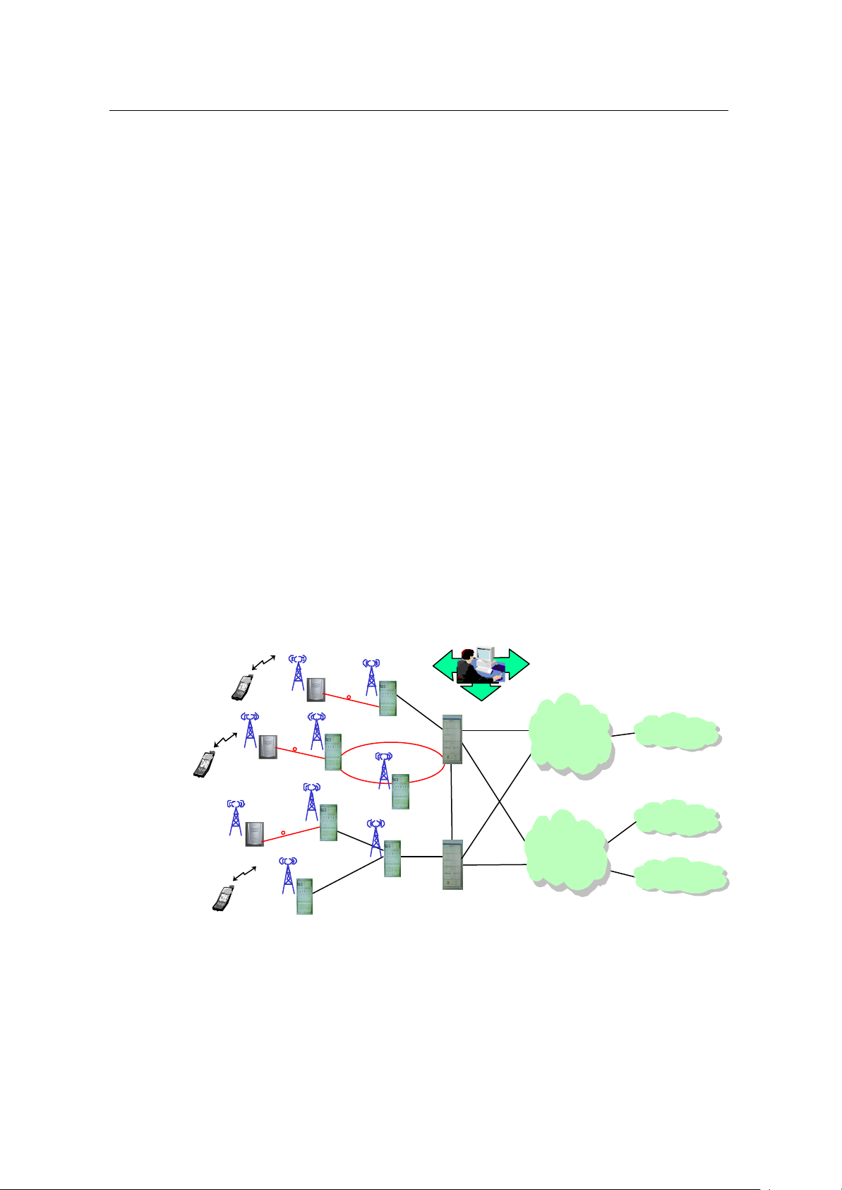
cBTS3612 cabinet is shown in Figure 1-2.
System Description
1 System Overview
Baseband subrack
Fan subrack
Power subrack
CDU/RLDU subrack
RF subrack
Figure 1-2 cBTS3612 cabinet
cBTS3612 has the following functions:
I. Interface function
RF subrack
l Um interface supports IS2000 Release A. It is fully compatible with IS-95A/B.
l The physical layer supports a rate as high as 307.2kbit/s.
l Hard handoff, soft handoff and softer handoff are supported.
l Quick forward power control, slow forward power control, quick reverse power
control and reverse open-loop power control are available.
1-2
Page 20

User Manual
Airbridge cBTS3612 CDMA Base Station
l Support omni -cell, directional 3 sectors and 6 sectors configurations.
l Abis interface supports E1/T1 trunk mode and optical fiber transmission mode
(optical fiber transmission mode will be available in the coming version). E1/T1
trunk mode supports as many as 16 E1/T1 trunk lines and optical fiber
transmission mode will support 2 pairs of STM-1 optical fibers .
l Chain, star and tree networking modes are supported.
l Softsite (ODU3601C) can be extended afar via optical fibers.
II. Basic functions of operation and maintenance
l Software downloading
l Abis interface management
l Air interface (Um) management
l Test management
l Status management
l Event report handling
l Equipment management
l Data configuration management
l BTS operation tracing
l Telnet logon
System Description
1 System Overview
1.2 System Features
cBTS3612 features large capacity, high integration and low power consumption.
One cabinet can accommodate as many as 12 sector carriers. It can satisfy the
customer's demands on capacity, configuration, installation, power supply,
transmission and service. It's a typical "All In One" BTS. Its features are highlighted
as follows:
1.2.1 Advanced Technology and Excellent Performance
cBTS3612 integrates the following technologies to improve its performances:
l Based on well-developed Huawei ATM platform and cell switching & broadband
processing technology, standard interface and open application is enabled.
l Designed with the resource pool concept, which helps increase the availability
of hardware resources and the system's fault -tolerance.
l Equipped with the digital intermediate frequency technology to enhance
wireless signal transmitting and receiving capability.
l Designed with the technology of diversity receiving to improve the radio signal
receiving performance.
l Supporting remote installation of the SoftSite via optical fibers, thus making
networking more flexible.
1-3
Page 21

User Manual
Airbridge cBTS3612 CDMA Base Station
l Equipped with the blind mate technology on the radio frequency module for
convenient maintenance.
l Intelligent fans with prolonged service life and reduced noise.
1.2.2 Protecting User Investment
The cBTS3612 is compatible with IS-95A/B and cdma2000 1X, and can be
upgraded to cdma2000 1X EV smoothly. When the network is upgraded from IS-95
to cdma2000 1X, or from cdma2000 1X to cdma2000 1X EV, the user's investment
can be saved.
The cBTS3612 features large-capacity design, modular structure and high
integration. A single cabinet can accommodate up to 12 sector carriers. It also
supports 36 sector carriers with three fully configured cabinets combined together.
Its baseband processing employs the resources pool design to reduce equipment
redundancy and improve reliability.
System Description
1 System Overview
Its Abis interface supports 16 E1s or 2 STM-1 optical interfaces (in the coming
version), oriented to future high-speed data service.
Its excellent inheritance capability guarantees the original antenna and feeder
components can be used in the event of BTS expansion or upgrade. The
components include DU, RLDU, antenna, feeder and the optional TMA (The TMA
only applies to 19000MHz band). The DU includes CDU, DFU and DDU, the
difference between these 3 DUs will be introduced in " 2.3 RF Subsystem".
1.2.3 Convenient Operation and Maintenance
Emergency serial ports are provided for the boards, so that the alarm information
can be reported in the case of communication link fault.
Real-time status query, online board test and system fault locating as well as system
restart functions are provided.
Telnet Server is provided so that the user can log in to the BTS via the local
Ethernet interface in the standard Telnet mode to perform O&M.
Modem dial-up is supported so that the remote O&M can be performed.
All boards of baseband subrack support hot plug/unplug for the sake of ready
maintenance, upgrade and expansion.
Blind mate of the radio frequency module guarantees that all operations can be
done at the front side of the equipment. During expansion and configuration, wiring
at the back need not be modified.
1-4
Page 22

User Manual
Airbridge cBTS3612 CDMA Base Station
Its modularized structure reduces the internal connections and improves the
reliability of the system, and thus makes the installation and maintenance easier.
In the case of whole BTS interruption due to power supply or transmission causes,
the cBTS3612 system can restart automatically right after the faults are cleared.
1.2.4 Flexible Networking Mode
I. Networking for large capacity and wide coverage
l A single cabinet supports as many as 12 sector carriers. 3 cabinets can be
combined to provide a maximum capacity of 36 sector carriers .
l Large-capacity trunk. Abis interface of BTS supports as many as 16 E1s
transmission. The coming version will support STM-1 optical transmission in
ATM mode at Abis interface and provide two STM -1 ports for Abis interface
trunk.
l Support multiple BTS configurations such as omni 4 carriers , 1%3, 2%3, 12%3,
6%6(carrier%sector) configurations.
System Description
1 System Overview
II. Supporting multiple BTS networking modes such as chain, star and tree
Refer to "4.1 Transmission Networking" for details.
III. Soft BTS networking (the SoftSite will be available in the coming version)
In this networking mode, the baseband unit adopts the centralized processin g mode.
The baseband signals and maintenance information are transferred through the fiber
to the SoftSite (ODU3601C). The SoftSite can be applied indoors, outdoors or
underground.
The SoftSite, small in size, is equipped with built-in power supply, temperature
regulator and monitoring device. It can be used in severe environments, e.g.
outdoors. The feeder loss of the SoftSite is trivial, making large coverage for macro
cells possible.
SoftSites in the chain-networking mode are applicable to highways and subways. A
maximum of 6 SoftSites can be connected in serial in one pair of optical fibers.
1.2.5 Reliable Power Supply System
The DC/DC power supply with -48V DC power input, and +27V DC output is
adopted. The whole power supply system is composed of 5 modules in full
configuration, with automatic current equalization function, 4+1 redundancy, meeting
the requirement of 8000W power supply.
1-5
Page 23

User Manual
Airbridge cBTS3612 CDMA Base Station
Current equalization hot backup, centralized management, and decentralized power
supply are enabled. It makes the power supply system safer and more reliable. It
provides automatic alarming through monitoring interface for the power fan, input
under-voltage, output over-voltage, overheat and protection against reverse
connection. This ensures the reliability of the power system. Remote power on/off
function enables unattended BTS operation and remote maintenance.
1.2.6 Multi-band supported
Now the cBTS3612 base station support the following band class specified in
TIA/EIA-97-D Recommended Minimum Performance Standards for cdma2000
Spread Spectrum Base Stations.
Band Class 0 (800 MHz Band ).
Band Class 1 (1900 MHz Band).
Band Class 5 (450 MHz Band ).
System Description
1 System Overview
To support the different band classes, RF modules with different specifications
should be configured in cBTS3612 base station.
1.3 Technical Index
I. Structure and environment indices
Cabinet dimensions (Top set excluded)
Power supply
Operational environment
Equipment room noise
&
Note:
In terms of environment adaptability, cBTS3612 conforms to the following specifications: IEC 60721-3
series, IEC 60068-2 and ETS 300 019-2 series. For details, please refer to Appendix C Environment
Performance.
Equipment room noise is In compliance with ETS 300 753 Noise Requirement for telecommunication
equipment and base station environment. When the inside temperature of cBTS3612 equipment room
is 50âC, the equipment noise is less than 70dBA, and when the temperature is 25âC, the equipment
noise is less than 60dBA.
1800mm x 800mm x 650mm (H x W x D)
-48V DC (-40 - -60V DC)
Temperature: -5°C ~ 50°C
Relative humidity: 5% ~ 90%
70dB A (With intelligent fan control. The noise varies with the
ambient temperature)
1-6
Page 24

User Manual
Airbridge cBTS3612 CDMA Base Station
II. Clock indices
System Description
1 System Overview
Frequency stability
Annual aging rate
<±5 x 10⁻⁸
<±5 x 10⁻¹⁰
III. System capacity
Full configuration of one cabinet
Full configuration of three cabinets
12 sector-carriers
36 sector-carriers
IV. Power consumption and cabinet weight
Site configuration Power consumption (W) Cabinet weight (kg)
S(1/1/1) <1500 351
S(2/2/2) <2800 388
S(4/4/4) <5500 550
V. Transmitter indices
l 450MHz Band
Working band
Channel bandwidth
Channel precision
Frequency tolerance
Transmitting power
l 800MHz Band
Working band
Channel bandwidth
Channel precision
Frequency tolerance
Transmitting power
l 1900MHz Band
460 - 470MHz
1.23MHz
25kHz
±0.05ppm
20W (The maximum value measured at the cabinet-top
feeder port)
869 - 894MHz
1.23MHz
30kHz
±0.05ppm
20W (The maximum value measured at the cabinet-top
feeder port)
1-7
Page 25

User Manual
Airbridge cBTS3612 CDMA Base Station
Working band
System Description
1 System Overview
1930 - 1990MHz
Channel bandwidth
Channel precision
Frequency tolerance
Transmitting power
VI. Receiver indices
l 450MHz Band
Working band
Channel bandwidth
Channel precision
Sensitivity of signal receiver
l 800MHz Band
Working band
Channel bandwidth
Channel precision
Sensitivity of signal receiver
1.23MHz
50kHz
±0.05ppm
20W (The maximum value measured at the cabinet-top
feeder port)
450 - 460MHz
1.23MHz
25kHz
Better than -126dB (RC3, main and diversity receiving)
824 - 849MHz
1.23MHz
30kHz
Better than –127dBm (RC3, main and diversity receiving)
l 1900MHz Band
Working band
Channel bandwidth
Channel precision
Sensitivity of signal receiver
1850 - 1910MHz
1.23MHz
50kHz
Better than –126dBm (RC3, main and diversity receiving)
VII. Rate configuration on Um interface
Rate configuration Forward Reverse
Mode 1 RC1 RC1
Mode 2 RC2 RC2
Mode 3 RC3 or RC4 RC3
Mode 4 RC5 RC4
1-8
Page 26

User Manual
Airbridge cBTS3612 CDMA Base Station
VIII. EMC indices
ETSI EN 300 386 Electromagnetic compatibility and Radio spectrum Matters (ERM)
- Telecommunication network equipment - ElectroMagnetic Compatibility (EMC)
requirements is the universal EMC standard of telecommunication equipment. The
EMC indices of the cBTS3612 comply with ETSI EN 300 386 V1.2.1 (2000 – 03).
IX. System reliability
System Description
1 System Overview
MTBF (hour)
MTTR (hour)
Availability (A)
&
Note:
The performance of cBTS3612 base station satisfies or excels TIA/EIA-97-D: Recommended Minimum
Performance Standards for cdma2000 Spread Spectrum Base Stations.
1.4 External Interface
1.4.1 Overview
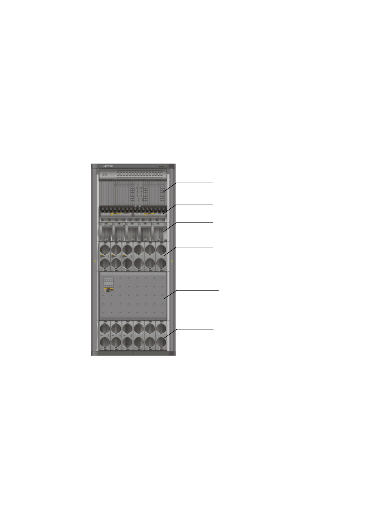
The external interfaces of cBTS3612 are shown in Figure 1-3.
100000
1
99.999%
1-9
Page 27
User Manual
Airbridge cBTS3612 CDMA Base Station
System Description
1 System Overview
Satellite
Um
interface
Synchronization
interface
MS
Figure 1-3 BTS external interface
equipment
Test
interface
Ethernet
interface
Test
LMF
Environment
alarm box
Environment
alarm interface
BTS
Abis interface
Remote maintenance serial port
MODEM
OML
interface
PSTN
BSC
OMC
l Um interface: interface with MS.
l Abis interface: interface with BSC.
l OML interface: interface with the remote OMC. It shares the transmission
resources with Abis interface.
l LMF interface: interface with BTS local maintenance console.
l System synchronization interface: including GPS/GLONASS antenna interface
and system external synchronization interface. When GPS/GLONASS is not
available and there is other clock synchronization equipment, the clock
synchronization output of the equipment can be connected with the external
synchronization interface of BTS system.
l BTS test interface: interface for BTS test, providing such signals as 10MHz and
2s signal.
l Remote maintenance serial interface: another interface to remote console. This
is a standby maintenance interface can be used when the active maintenance
link between OMC and BTS is interrupted.
l Environment alarm interface: interface with environment alarm collection box.
1.4.2 Um Interface
I. Overview
In Public Land Mobile Network (PLMN), MS is connected with the fixed part of the
network through the radio channel, which enables the subscribers to be connected
1-10
Page 28
User Manual
Airbridge cBTS3612 CDMA Base Station
with the network and to enjoy telecommunication services. To implement
interconnection between MS and BSS, systematic rules and standards should be
established for signal transmission on radio channels. The standard for regulating
the radio channel signal transmission is called radio interface, or Um interface.
Um interface is the most important interface among the many interfaces of CDMA
system. Firstly, standardized radio interface ensures that MSs of different
manufacturers are fully compatible with different networks. This is one of the
fundamental conditions for the roaming function of CDMA system. Secondly, radio
interface defines the spectrum availability and capacity of CDMA system.
Um interface is defined with the following features :
l Channels structure and access capacity.
l Communication protocol between MS and BSS.
l Maintenance and operation features .
l Performance features .
l Service features.
System Description
1 System Overview
II. Um interface protocol model
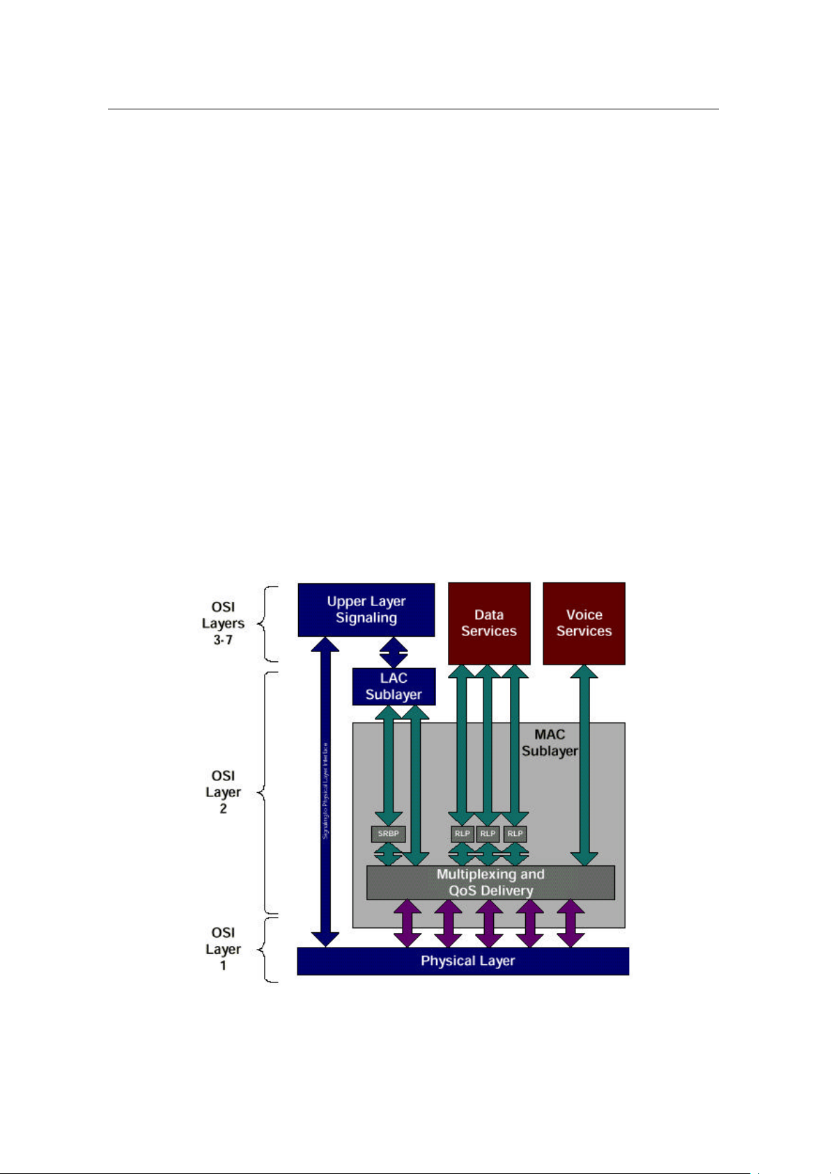
Um interface protocol stack is in 3 layers, as shown in Figure 1-4.
Figure 1-4 Um interface layered structure
1-11
Page 29

User Manual
Airbridge cBTS3612 CDMA Base Station
l Layer 1 is the physical layer, i.e. the bottom layer. It includes various physical
channels, providing a basic radio channel for the transmission of higher layer
information.
l Layer 2 is the data link layer, including Medium Access Control (MAC) sublayer
and Link Access Control (LAC) sublayer. The cdma2000 MAC sublayer
performs the mapping between logic channels and physical channels, and
providing Radio Link Protocol (RLP) function. The cdma2000 LAC sublayer
performs such functions as authentication, Automatic Repeat Request (ARQ),
addressing and packet organization.
l Layer 3 is the top layer. It performs Radio Resource Management (RM),
Mobility Management (MM) and Connection Management (CM) through the air
interface.
III. Physical layer
1) Operating band
System Description
1 System Overview
Band Forward Band Reverse Band Duplex
Channel
Carrier Space
450MHz 460 - 470MHz 450 - 460MHz 10MHz 1.23 MHz 1.23 MHz
800MHz 869 - 894 MHz 824 - 849 MHz 45MHz 1.23 MHz 1.25 MHz
1900MHz 1930 - 1990 MHz 1850 - 1910 MHz 80MHz 1.23 MHz 1.25 MHz
2) Physical layer function
l Service bearer: the physical channel in the physical layer provides bearer for
the logic channel of the higher layer.
l Bit error check: the physical layer provides a transmission service with error
protection, including error checking and error correction.
l User identification: the physical layer provides an exclusive ID for every user by
code division.
3) Radio configuration
The cdma2000 physical layer supports multiple Radio Configurations (RCs).
Different RCs support different traffic channel data rates. For detailed introduction,
please refer to Section 4.5.4 Radio Configuration and Channel Support.
IV. Data link layer
Data link layer at Um interface includes two sublayers: MAC and LAC. The purpose
of introducing MAC and LAC is to:
l Support higher level services (signaling, voice, packet data and circuit data).
l Support data services of multiple rates.
l Support packet data service and circuit data service of higher quality (QoS).
1-12
Page 30

User Manual
Airbridge cBTS3612 CDMA Base Station
l Support multi-media service, i.e. processing voices, packet data and circuit
data of different QoS levels at the same time.
1) MAC sublayer
To support data service and multi -media service, cdma2000 1X provides powerful
MAC layer to ensure the reliability of services. MAC layer provides two important
functions:
l Radio Link Protocol (RLP), ensuring reliable transmission on the radio link.
l Multiplex function and QoS function, with diversified services and higher service
quality.
2) LAC sublayer
LAC layer performs such functions as Automatic Repeat Request (ARQ),
authentication and addressing.
V. Layer 3
System Description
1 System Overview
The higher layer signaling performs the functions such as radio resource
management, mobility management and call control management on air interface.
1) Radio resource management
It is mainly used to establish, operate and release radio channels, and help to
realize soft handoff, softer handoff and hard handoff.
2) Mobility management
It is mainly used to support the mobility features of the mobile user, performing such
functions as registration, authentication and Temporary Mobile Subscriber Identifier
(TMSI) re -allocation.
3) Connection management
It is mainly used to setup, maintain and terminate calls.
VI. Power control
Um interface utilizes power control technology to reduce the system interference
and improve the system capacity. There are forward power control and reverse
power control available.
1) Forward power control supports closed -loop power control
Forward power control includes power control based on power measurement report,
control based on EIB, and quick forward power control.
Forward closed-loop power control means that MS checks the quality of received
frames and received power, makes judgment and sends request to BTS for
1-13
Page 31

User Manual
Airbridge cBTS3612 CDMA Base Station
controlling BTS transmitting power. Then BTS adjusts its transmitting power
according to the request. Power control command is sent at a rate of 50bit/s or
800bit/s.
2) Reverse power control inc ludes open-loop power control and closed -loop power
control.
l Reverse open-loop power control means that MS adjusts its transmit power as
the received power changes.
l Reverse closed-loop power control means that BTS compares the received MS
transmit power with the preset power control threshold and sends power control
command based on the comparison. MS changes its transmit power as
required by the received power control command. Power control commands are
transmitted on F-TCH at a rate of 800bit/s.
For more information about power control, please refer to Section 4.5.1 Power
Control.
VII. Handoff
System Description
1 System Overview
Um interface supports many handoff technologies. It supports three types of handoff
in traffic channel communication:
1) Hard handoff: MS breaks the connection with the old BTS before establishing
connection with a new BTS.
2) Soft handoff: MS establishes connection with a new BTS while maintaining the
connection with the existing one.
3) Softer handoff: soft handoff that occurs between different sectors of the same
BTS.
Soft handoff technology can improve the rate of handoff success, reduce call drops
and effectively improve the system performance.
For more information, please refer to Section 4.5.2 Handoff.
1.4.3 Abis Interface
I. Overview
Abis interface is defined as the interface between BSC and BTS, the two functional
entities in the Base Station Subsystem (BSS ). It is the interface defined for BTS
accessing BSC via the terrestrial link.
1-14
Page 32

User Manual
MC: Main Control
Airbridge cBTS3612 CDMA Base Station
1) Composition of Abis interface
Abis interface consists of three parts: Abis traffic, Abis signaling and OML signaling,
as shown in Figure 1-5.
Abis traffic is the interface connecting SDU of BSC and the channel processing unit
of BTS. It is used to bear user traffic.
Abis signaling is the signaling transmission channel between BSC and BTS. It is
used to control the cell setup, transmission of messages in paging channels and
access channels, and call setup & release.
OML signaling is used to perform operation and maintenance. It is defined by
equipment manufacturers. On Abis interface, there is a transparent channel used to
bear OML between OMC and OMU of BTS.
System Description
1 System Overview
SPU SDU
BSC
Abis Signaling
Abis Traffic
Abis Interface
MC
SPU:Signaling Process Unit
SDU:Selection/Distribution Unit
Abis Traffic
Abis Signaling
CEs
OMU
BTS
OML
OML
CEs
OMU
CEs: Channel Elements
OMU:Operation & Maintenace Unit
MC
BTS
Figure 1-5 Composition of Abis interface
2) Protocol stack of Abis interface
The protocol stack used by Abis signaling and the signaling for operation &
maintenance is as follows:
Abis Signaling Application/OAM Application
TCP
IP
AAL5
ATM
Physical Layer
1-15
Page 33

User Manual
Airbridge cBTS3612 CDMA Base Station
Protocol stack used by Abis traffic is as follows :
Abis Traffic
SSSAR
AAL2
ATM
Physical Layer
II. Physical layer
The physical layer of A bis interface can use E1/T1 interface or STM -1 interface.
With E1/T1 interface used, its physical electric parameters comply with CCITT
G.703 recommendations. The multiple E1/T1 trunk lines transmit ATM cells by
means of Inverse Multiplexing on ATM (IMA).
III. Data link layer
ATM is used in the data link layer of Abis interface.
System Description
1 System Overview
Adaptation of Abis signaling is performed on the basis of AAL5, and is borne in IP
Over ATM (IPoA) mode. At Abis interface, Abis signaling path connects the main
control software (MC) and SPU of BSC via Permanent Virtual Circuit (PVC) to
transmit Abis signaling. So it is with the transmission path of signaling that performs
operation & maintenance. It also uses PVC to connect OMU of BTS and BSC, which
will forward it to OMC transparently. BSC does not process any signaling that
performs operation and maintenance.
Adaptation of Abis traffic is performed on the basis of AAL2. At Abis interface,
BCPM uses several PVCs to connect the channel processing unit of BTS and SDU
of BSC, for BTS to transmit the uplink data received from the air interface to BSC,
and for BSC to transmit the downlink data to be transmitted via the air interface to
BTS.
IV. Layer 3 - traffic management
At Abis interface, Abis signaling and Abis traffic are in the domain of traffic
management. Specifically, Abis traffic management includes the following functions:
1) BTS logic operation & maintenance function
l Resource status indication: with this function, BTS requests logic configuration
from BSC, reports logic status to BSC and checks logic resource regularly.
l Cell configuration: with this function, BSC configures logic parameters of cells
for BTS, including cell pilot Pseudo Noise (PN) offset, sector gain, common
channel number and parameter.
l Overhead message updating: with this function, BSC configures or update
overhead message to BTS .
1-16
Page 34

User Manual
Airbridge cBTS3612 CDMA Base Station
l Cell breath control function.
l Cell blocking function.
l Radio measurement report function.
2) Common channel management procedure
Paging channel management procedure: it is used to transmit paging channel
messages from BSC to MSs through Abis interface.
Access channel management procedure: it is used to transmit access channel
messages received on the access channel of BTS to BSC through Abis interface.
3) Procedure of dedicated channel setup and release
It is used to control the setup and release of dedicated radio channel and Abis
interface terrestrial channel.
Abis interface supports the setup and release of various dedicated channels
specified in IS95A/B and cdma2000 1X, specifically including IS95-FCH,
IS95-SCCH, IS2000-FCH, IS2000-DCCH and IS2000 -SCH.
System Description
1 System Overview
Each radio channel is allocated with one AAL2 link on Abis interface to bear user
traffic data.
Caution:
Softer handoff is only allocated with one AAL2 link on Abis interface.
4) Traffic channel bearing procedure
BTS needs to process Abis interface frame protocol, to transmit the data received
from the reverse traffic channel on the air interface to BSC and the data from BSC
through the forward traffic channel at the air interface.
Traffic channel bearing procedure also performs functions such as AAL2 traffic
matching, time adjustment of traffic data frame, reverse outer loop power control
adjustment and forward power control adjustment.
5) Power control
Abis interface supports various power controls. Power control is performed through
parameter configuration. Power control falls into 4 types: quick forward closed -loop
power control, slow forward closed-loop power control, quick reverse closed -loop
power control and reverse open -loop power control.
1-17
Page 35

User Manual
Airbridge cBTS3612 CDMA Base Station
1.4.4 OML Interface
OML interface is between BTS and remote OMC. It is actually one of the Abis
interface applications, but in the application layer, OML interface is between BTS
and the remote OMC. OML interface shares resources of Abis interface, including
physical layer, ATM, AAL5 and TCP/IP. For details, please refer to the introduction to
Abis interface.
OML interface is used for OMC to perform operation and maintenance to BTS. It is
defined by equipment manufacturers. On Abis interfac e, it is a transparent path.
1.4.5 LMF Interface
LMF interface is the interface between BTS and Local Maintenance Function (LMF).
Its interface protocol stack is shown as below:
LMF Signaling Application (self-defined)
TCP
IP
Data Link Layer
Physical Layer (10/100 Base-T)
System Description
1 System Overview
1.4.6 System Synchronization Interface
System synchronization interface includes GPS/GLONASS antenna interface and
system external synchronization interface.
1) GPS/GLONASS antenna interface: GPS is in compliance with ICD200c:
IRN-200C-001-IRN-200C-004: Interface Control Document of GPS. GLONASS is in
compliance with GPS/GLONASS Receiver Interface Language (GRIL).
2) System external synchronization interface: the external synchronization interface
without GPS/GLONASS is in compliance with the requirement of CDMA Digital
Cellular Mobile Communication Network GPS/GLONASS Dual-Mode Receiver and
Base Station Interface Specifications.
1.4.7 BTS Test Interface
BTS test interface provides 10MHz and 2s signals that may be necessary for
testers.
1-18
Page 36

User Manual
Airbridge cBTS3612 CDMA Base Station
1.4.8 Remote Maintenance Serial Port
Remote maintenance serial port is an RS -232 serial port, connected with PSTN via
an external Modem. It is used for emergency maintenance by dial -up with a Modem
when OML between OMC and BTS is interrupted.
1.4.9 Environment Alarm Interface
Environment alarm interface is an RS-485 serial port connected with the external
environment alarm collection box, performing a centralized monitoring to the
environment. A communication protocol defined by Huawei is used between BTS
and the environment alarm collection box. Therefore, supported environment alarm
collection box should be used for the BTS.
1.5 Reliability Design
Reliability design of a system is shown in the stability and reliability of the product
during operation.
System Description
1 System Overview
Huawei cBTS3612 is designed based on reference to the following standards:
l YD/T 1029-1999 800MHz General Technical Specifications of CDMA Digital
Cellular Mobile Communication Network Equipment
l YD/T 1030 -1999 800MHz Technical Requirement for Interface of CDMA Digital
Cellular Mobile Communication Network
l TIA/EIA/IS-97D Minimum Performance Standard of CDMA Base Station
l Huawei product reliability design index and related technical specifications
The design of boards is in strict accordance with the requirement of above
standards pertaining to reliability design, with measures taken to improve the
reliability. In addition, some key parts of the system are designed with redundancy
(such as active/standby mode and resource pool) to improve the reliability of the
system.
System reliability indices are:
MTBF: 100000 hours MTTR: 1 hour A : 99.999%
1-19
Page 37

User Manual
Airbridge cBTS3612 CDMA Base Station
&
Note:
Reliability refers to the product capability of performing specified functions in the specified conditions
and specified time.
There are 3 main indices to describe the reliablity of a system:
MTBF: Mean Time Between Failures, normally applicable to recoverable systems.
MTTR: Mean Time To Repair, inlcuding the time of fault checking, isolation, unit replacement and
recovery.
A: Availability, a comprehensive index to measure the system availability.
1.5.1 Hardware Reliability Design
cBTS3612 is designed with substantial hardware reliability, such as board
active/standby operation, load sharing and redundancy configuration. In addition,
system maintainability is improved with fault detection and isolation technology on
the board and system. In respect of hardware reliability, the following considerations
have been taken:
System Description
1 System Overview
I. De-rating design
To improve system reliability and prolong the service life of components,
components are carefully selected and strictly tested, and less stress (electrical
stress and temperature stress) is to be borne than its designed rating.
II. Redundancy design
Redundant configuration of key units is applied in the BTS system. The system or
equipment will not fail unless the specified sets of units fail. In the BTS system,
common measures such as active/standby and load-sharing modes are adopted,
e.g. for BCIM, BCPM and BCKM.
III. Selection and control of components
The category, specifications and manufacturers of the components are carefully
selected and reviewed according to the requirements of the product reliability and
maintainability. The replaceability and normalization of components is one of the
main factors for the decision, which help to reduce the types of components used
and hence improve the availability of the system.
1-20
Page 38

User Manual
Airbridge cBTS3612 CDMA Base Station
IV. Board level reliability design
Many measures have been taken to improve the board reliability. Moreover, the
system reliability is improved through the redundancy design of key parts.
l Key circuits are designed by Huawei, which lays the foundation of high
reliability.
l The hardware WATCHDOG is equipped for the board, and the board can
automatically reset in case of fault.
l The board is provided with the functions of over-current and over-voltage
protectio n and the function of temperature detection.
l The board also provides emergency serial port, and can keep contact with the
main control board in case of emergency.
l Strict thermal analysis and simulation tests are conducted during the design of
boards for the purpose of ensuring longtime operation.
l The board software and important data is stored in the non-volatile memory, so
that the board can be restarted when the software upgrading fails.
System Description
1 System Overview
V. Overvoltage and overcurrent protection
The BTS system provides various means of over-voltage and over-current
protection.
l Over-voltage and over-current hardware protection is provided for the DC/DC
power supply module.
l For secondary power supply to boards, slow-start is employed to prevent the
great impact on the whole power supply load when the boards are powered on.
Fuse is installed for each board against over-current.
l For E1 interface circuit, serial-port circuit and network interface circuit,
protection measures are taken in accordance with the corresponding design
specifications of Huawei.
VI. Power supply reliability
The reliability of power supply is improved by means of over-current and
over-voltage protection, internal temperature adjustment, and redundancy backup.
VII. Fault detection, location and removal
The BTS system is equipped with the functions of self-detection and fault diagnosis
that can record and output various fault information. The common software and
hardware faults can be corrected automatically.
The hardware fault detection functions include fault locating, isolating and automatic
switchover. The maintenance engineers can identify the faulty boards easily with the
help of the maintenance console.
1-21
Page 39

User Manual
Airbridge cBTS3612 CDMA Base Station
When faults occur to software, certain automatic error-correction function will be
executed, includin g restarting and reloading.
The BTS system also provides manual and automatic re-initialization of different
levels, and supports the reloading of configuration data files and board execution
programs.
System Description
1 System Overview
VIII. Fault tolerance
When faults occur, the system usually will not be blocked, as the BTS system
provides the E1 connection in conformity with the IMA protocol, and has certain line
backup capabilities.
The boards of important devices in the system have been backed up, ensuring that
the BTS system can switch the service from the faulty board to a normal board, or
perform reconfiguration of the system.
The system will make a final confirmation on a hardware fault through repeated
detection, thus avoiding the system reconfiguration or QoS deterioration due to
contingent faults.
IX. Thermal design
The influence of temperature on the BTS system has been considered in the design
of the system. Thermal design primarily concerns the selection of components,
circuit design (including error tolerance, drift design and derating design), structure
design and heat dissipation, so that the BTS system can work reliably in a wide
range of temperatures.
The first consideration in thermal design is to balance the heat distribution of the
system. Corresponding measures are taken i n the place where heat is more likely to
be accumulated.
X. Maintainability
The purpose of maintainability design is to define the workload and nature of the
maintenance, so as to cut the maintenance time. The main approaches adopted
include standardization, modularization, error prevention, and testability
improvement which can simplify the product maintenance work.
XI. EMC design
The design ensures that cBTS3612 will not degrade to an unacceptable level due to
the electromagnetic interference from other equipment in the same electromagnetic
environment. At the same time, cBTS3612 will not cause other equipment in the
1-22
Page 40

User Manual
Airbridge cBTS3612 CDMA Base Station
same electromagnetic environment to degrade to an unacceptable level due to the
EMI from it.
System Description
1 System Overview
XII. Lightning protection
To eliminate the probability of lightning damage on the BTS system, proper
measures are taken in the following three aspects:
l Lightning protection for DC power supply
l Lightning protection for BTS trunk lines
l Lightning protection for antenna and feeder system
For details, please refer to "2.7 Lightning Protection System".
1.5.2 Software Reliability Measures
Software reliability mainly includes protection performance and fault tolerance
capability.
I. Protection performance
The key to improve software reliability is to reduce software defects. Software
reliability of BTS is ensured in the whole process from system requirement analysis,
system design to system test.
Starting from the requirement analysis, software development process goes under
regulations such as CMM (Capability Mature Mode), which aim to control faults in
the initial stage.
In software design, much attention is devoted to the designing method and
implementation: the software is designed in a modular structure, and in a loose
coupling mechanism. When a fault occurs to one module, othe r modules will not be
affected. In addition, preventive measures such as fault detection, isolating and
clearing are also important in improving the system reliability. Other effective
methods include code read-through, inspection, and unit test.
Various software tests are necessary to improve the software reliability. Test
engineers participate the whole software develop process, from unit test to system
test. They make plans strictly compliant with the demand of the upper level flow,
which ensure the improvement of software reliability. Additionally, test plans are
improved with the tests and become more and more applicable.
II. Fault tolerance capability
Fault tolerance capability of the software system means that the whole system
would not collapse when a minor software fault occurs, i.e. the system has the
1-23
Page 41

User Manual
Airbridge cBTS3612 CDMA Base Station
self-healing capability. The fault tolerance of software is represented in the following
aspects:
l All boards work in a real-time operating system of high reliability.
l Important data on BCKM are backed up on real-time basis. Operation is
switched to the standby board when a fault occurs.
l When a fault occurs to some transmission links, traffic borne on them can be
transferred to other links smoothly.
l Each board's software on the board has a static backup on B CKM.
l If software loading fails, the system can return to the version that was loaded
successfully last time.
l Important operations are recorded in log files.
l Different authority levels are provided for operations, to prevent users from
performing unauthorized operations.
l Prompts are given for the operations that will cause system reboot (such as
reset operation), which requests the operator to confirm it before executing
such operation.
System Description
1 System Overview
1-24
Page 42

User Manual
Airbridge cBTS3612 CDMA Base Station
2 Hardware Architecture
The beginning of this chapter briefs cBTS3612 hardware architecture, followed by
the details of four subsystems: baseband, RF, antenna & feeder, and power supply
system. This chapter also covers BTS environment monitoring and lightning
protection systems.
2.1 Overview
In cdma2000 1X mobile communication system, BTS functions as a radio relay. One
end is connected with MS through Um interface and the other end connected with
BSC through Abis interface.
The architecture of BTS is as shown in Figure 2-1.
System Description
2 Hardware Architecture
Test
LMF
BFMM
External
Abis interface
Test interface
RS232
Ethernet port
RS485
RS485
-48VDC
GND
RS485
BSC
equipment
Modem
Environment alarm
collection
synchronization
GPS/GLONASS receive antenna
Figure 2-1 BTS architecture
BCIM
BCKM
Backplane
Clock bus
bus
Baseband
subsystem
BCPM
Emergency
serial port
High-speed data bus
BRDM
...
Optical fiber
RS485
Optical fiber
RS485
POWER
Power supply
subsystem
Um interface
BHPA
BTRM
BBFM
BHPA RF receive/ transmit
BHPA
BHPA CDU
BTRM
BTRM
BBFM
CDU
RLDU
RLDU
RF subsystem
RF receive/ transmit
antenna
Um interface
antenna
+27VDC
GND
2-1
Page 43

User Manual
Airbridge cBTS3612 CDMA Base Station
&
Note:
In Figure 2-1, the duplexer is CDU, and actually the right duplexer should be selected according to the
band class BTS supported. CDU applies to 800MHz band and 450MHz band, DFU applies to
450MHz band, and DDU applies to 1900MHz band, as for the difference between the CDU, DFU and
DDU, please refer to " 2.3 RF Subsystem".
BTS is mainly composed of baseband subsystem, RF subsystem, antenna & feeder
subsystem (which comprises RF receive/transmit antenna and GPS/GLONASS
receive antenna) and power supply subsystem. Baseband subsystem in physical
structure also carries a clock synchronizat ion unit, receiving GPS/GLONASS clock
and providing system time, synchronous clock and frequency reference.
I. Baseband subsystem
The main functions of baseband subsystem are: processing Abis interface protocol,
modulating/demodulating baseband data, channel encoding/decoding, processing
protocols of physical layer and MAC layer on air interface, system
operation/maintenance and connecting baseband data optical interface of RF
module.
System Description
2 Hardware Architecture
Baseband subsystem is located in the BTS baseband subrack. It consists of BTS
Control & Clock Module (BCKM), BTS Resource Distribution Module (BRDM), BTS
Channel Processing Module (BCPM ), BTS Control Interface Module (BCIM) and
CDMA Baseband Backplane Module (CBKM). Functions of all boards are
highlighted as follows:
1) BCKM
At most 2 BCKMs are configured in hot standby. BCKM receives GPS signals (or
other synchronization satellite signals), generates local clock and provides time
signals 16%1.2288MHz, 10MHz, PP2S for the boards in the system. This is mainly
the responsibility of the clock module of BCKM. Besides clock signal, BCKM also
provides main control function for channel resources. Its MPU module performs a
number of operations and functions such as resource management, equipment
management, performance monitoring, config uration management, software
downloading, MPU active/standby switchover, operation & maintenance (O&M),
environment monitoring interface, as well as board control inside the system.
2) BRDM
BRDM is logically located between BTRM and BCPM. The data sent by BTRM
module are sent to BRDM via the optical fiber. Then BRDM distributes the data
before sending them to BCPMs via the high-speed data bus. BRDM can also build
2-2
Page 44

User Manual
Airbridge cBTS3612 CDMA Base Station
daisy chains for BCPMs. The BRDM connects via the shorter daisy chain provided
to BCPM to form a standard daisy chain, which helps to improve the utilization ratio
of channel resource and facilitates the flexible configuration of channel capacity for
each sector carrier. BRDM exchanges O&M information with BCKM through the
backplane bus . The emergency serial port of BRDM is attached on the UART of the
backplane as a standby node.
3) BCPM
BCPM processes BTS baseband signals, both for the forward traffic and reverse
traffic. For forward traffic, it performs functions such as encoding (convolutional code,
TURBO code ), interleaving, spectrum spreading, modulation and data multiplexing.
For reverse traffic, it performs functions such as demultiplexing, demodulation,
de-interleaving and decoding (convolutional code, TURBO code). Regarding the
user data flow, BCPM is between BRDM and BCIM.
4) BCIM
BCIM transfers data between BTS and BSC, including voices, data and O&M
commands. With the Inverse Multiplexing on ATM (IMA) technology, BCIM
multiplexes the BTS uplink data to IMA link set that is composed of multiple E1s,
and then transmits it to BSC via coaxial or optical fiber. Inversely, it can also
demultiplex the IMA link set signals from BSC into an ATM cell flow and transmit it to
BTS boards via the backplane bus.
System Description
2 Hardware Architecture
5) CBKM
CBKM performs interconnection of high-speed data links between boards in the
baseband part and the interconnection of various management and control signals
of boards.
II. RF subsystem
BTS RF subsystem is composed of five parts: BTS Transceiver Module (BTRM),
BTS High Power Amplifier Module (BHPA), BTS Transceiver Backplane Module
(BTBM ), Duplexer Unit and Receive LNA Distribution Unit (RLDU). Functions of all
parts are briefed as follows:
1) BTRM
BTRM consists of BTS Intermediate Frequency Unit (BIFU), and BTS Radio
up/down -conversion Unit (BRCU). Its functions are as follows:
BIFU: BIFU performs such functions as A/D conversion in the reverse receiving path
and D/A conversion in the forward transmitting path, digital frequency up/down
-conversion, received signal filtering, baseband molded signal filtering, Digit
Automatic Gain Control (DAGC), uplink & downlink RF Automatic Gain Control
2-3
Page 45

User Manual
Airbridge cBTS3612 CDMA Base Station
(AGC), multiplexing/demultiplexing of forward & reverse orthogonal (IQ) signals,
clock recovery and RF module operation & maintenance.
BIFU also performs the control over BTRM, including power-on initialization,
function configuration, alarm collection and reporting, and processing of O&M
related messages.
BRCU: BRCU is composed of 5 logic functional units: main/diversity transmit unit,
main/diversity receive unit and frequency source unit.
l Transmit unit realizes analog up-conversion and spurious suppressed filtering
for transmitted signals output by BIFU.
l Main/diversity receive unit realizes analog frequency down-conversion, channel
selective filtering and rec eived nose coefficient control for BTS main/diversity
received signals output by RLDU.
l Frequency source unit is responsible for the synthesis of the low phase noise,
high-stability local oscillation signals that are necessary for the analog
frequency conve rsion in transmit and receive paths.
System Description
2 Hardware Architecture
2) BHPA
BHPA performs high power linear amplification for a transmitted carrier signal,
checks its own working status in real time and generates alarm. It is composed of
main signal power amplification unit and signal detection alarm unit. Signal detection
is to check whether the input is too excited, whether the temperature is too high or
whether the gain is lowered strikingly (device failure).
3) BTBM
BTBM performs structure support and signal communication between BTRM and
BHPA.
4) Duplexer Unit
There are following three types of Duplexers. They can be configured according to
actual requirement s.
Combiner and Duplexer Unit (CDU): combining and filtering of two transmitting
carriers, transmitting and receiving signals duplexing and isolating, and diversity
receiving signal filtering. CDU operates at 800MHz band and 450MHz band.
Duplexer and Filter Unit (DFU): transmitting and receiving signal duplexing, isolating
and filtering of one channel, diversity receiving signal filtering. DFU operates at
450MHz band.
Dual Duplexer Unit (DDU): transmitting and receiving signals duplexing, isolating
and filtering of two channels, It does not provide combining function. DDU operates
at 1900MHz band.
2-4
Page 46

User Manual
Airbridge cBTS3612 CDMA Base Station
6) RLDU
RLDU performs low noise amplification and division of the receiving signals,
providing standing wave alarm and forward power checking voltage output, checking
the physical connection of the antenna port and monitoring whether the output of
BRCU, BHPA signals is normal.
III. Antenna & feeder subsystem
BTS antenna & feeder subsystem includes two parts: RF antenna & feeder and
dual-satellite synchronization antenna & feeder. The former mainly transmits the
modulated RF signals and receives MS information while the latter provides precise
synchronization for CDMA system.
IV. Power supply subsystem
Power supply subsystem consists of power input component (EMI filter, lightning
arrester of power supply), high power DC/DC power supply module, power
distribution box, medium/low power DC/DC power supply module for boards (or
modules ).
System Description
2 Hardware Architecture
The power supply subsystem provides power for the whole BTS.
2.2 Baseband Subsystem
2.2.1 Overview
The baseband subsystem is one of the major parts of BTS. Its structure is shown in
Figure 2-2.
2-5
Page 47

User Manual
Airbridge cBTS3612 CDMA Base Station
System Description
2 Hardware Architecture
BSC
E1
BCIM
BCPM
Emergency serial port
Clock bus
Backplane bus
High-speed
data bus
BCKM
BRDM
...
Optical fiber
Other functional
units
BTRM
Figure 2-2 Structure of baseband subsystem
Baseband subsystem is connected with BSC through Abis interface provided by
BCIM. The transmission in this subsystem is performed through E1 trunk (The
coming version will provide STM-1 optical transmission). BRDM and BTRM are
connected by optical fiber to support RF module extended afar mode.
Baseband subsystem also provides some other interfaces through BCKM:
l LMF interface: 10/100 Base-T interface, connecting Local Maintenance
Function (LMF).
l Remote maintenance serial port: The interface is an RS232 serial port,
connected with PSTN via an external Modem. When OML between OMC and
BTS is interrupted, maintenance can be performed through telephone line
dial-up connection.
l GPS/GLONASS antenna interface: It is used to receive clock signal from
GPS/GLONASS.
l System external synchronization interface: When GPS/GLONASS is not
available, it makes the system clock synchronized with external clock.
l Fan module interface: It is connected with fan module through RS485 serial
port, monitoring the fan module.
l Environment alarm interface: It is connected with an external environment
alarm collection box, providing environment monitoring alarm information of the
equipment and monitoring information of the primary power supply.
l Power monitoring interface: It is connected with power supply module, reporting
various alarm information of the power supply.
l Test interface: It is an interface for BTS test, providing 10MHz and 2s signals.
2-6
Page 48

User Manual
Airbridge cBTS3612 CDMA Base Station
Baseband subsystem is physically located in the baseband subrack, powered by
power supply subsystem (in the power subrack). Boards generate their own 3.3V,
1.8V power through the distributed power supply module.
The configuration of baseband subrack (including board position) is as shown in
Figure 2-3.
0
1
2
B
B
B
B
C
C
C
I
M
C
I
P
P
M
M
M
Figure 2-3 Baseband subrack configuration
System Description
2 Hardware Architecture
3
4
5
6
8
7
B
B
B
B
B
C
C
C
C
R
P
P
P
P
D
M
M
M
M
M
10 11 12 13 14 15 16 17 18 19 20 219
B
B
B
B
B
B
B
B
B
B
B
B
B
R
C
C
R
R
C
C
C
C
C
C
R
R
D
K
K
D
D
P
P
P
P
P
P
D
D
M
M
M
M
M
M
M
M
M
M
M
M
M
Baseband subrack supports the following boards:
l BCIM: BTS control interface module, to be inserted in E1 interface slot,
providing Abis interface for connection with BSC and supporting E1/T1
transmission. In the coming version, BCIM slot can also accommodate BEOM
(BTS Electric -Optical Module) to support STM-1 optical transmission.
l BCPM: BTS channel process board, processing the data of CDMA forward
channel and reverse channel.
l BRDM: BTS resource distribution module, connecting BCPM and RF module,
realizing the control of resource pool for BCPM.
l BCKM: BTS control & clock board, providing clock for BTS system and realizing
the control of BTS system resource.
2.2.2 Control & Clock Module (BCKM)
I. Overview
BCKM is located in the baseband subrack of BTS. BCKM performs two major
functions: main control module (MPU, Main Processing Unit) and clock module (CLK,
Clock) functions. Here MPU performs Abis interface signaling processing, O&M
management , while CLK provides reference clock signals for the whole BTS system.
Main functions of BCKM:
l MPU module provides BTS system with a hardware control platform, on which
the operating system and system software are running to implement control
and management tasks of BTS system.
2-7
Page 49

User Manual
Airbridge cBTS3612 CDMA Base Station
l Perform operation and maintenance via the backplane bus for other boards in
the baseband subrack, realizing in-band signaling communication.
l Connected with Local Maintenance Function (LMF) through the 10/100M
compatible Ethernet interface.
l The active/standby asynchronous serial port serves as a path for out-band
signaling backup. MPU functions as the main node and other boards function
as the standby nodes. When a fault occurs to the in-band signaling path,
signaling communication can be maintained with this standby path.
l Provide an interface connected with Modem in compliance with RS232 serial
communication standard, realizing remote maintenance and monitoring in case
of OML link failure.
l Connected with an external monitoring module in compliance with RS485
standard, collecting and processing the equipment room environment
information (such as fire alarm/water soaking/ temperature/humidity).
l CLK unit is the clock source of BTS system, providing working clock for all
boards. It provides high precision oscillation clock and can be synchronized
with an external clock (such as GPS clock).
l BCKM provides active/standby switchover function, working in active/standby
mode in the system. When a fault occurs to the active BCKM, the standby
BCKM is switched to active status under the control of specific software. A fault
occurring to either MPU or CLK module of the BCKM will result in the
switchover of the whole BCKM.
System Description
2 Hardware Architecture
II. Structure and principle
The structure of BCKM module is as shown in Figure 2-4.
BCKM
Other
functional units
...
External
communication
unit
Power supply
module
MPU module
Figure 2-4 Structure of BCKM module
Clock module
Backplane bus
module
CBKM
Backplane
bus
2-8
Page 50

User Manual
Airbridge cBTS3612 CDMA Base Station
BCKM comprises the following parts:
1) MPU module
MPU controls logic circuits to initialize components. It realizes control and
management over BTS system through system software.
2) Clock module
Clock module is the clock source of BTS, providing working clock for boards. Clock
module is available in two modes: external synchronization mode (locked mode ) and
free oscillation mode (holdover mode). The clock module can provide high -precision
oscillation clock (voltage control constant temperature crystal oscillator) or be
synchronized with external clock source (GPS, GLONASS, external synchronization
equipment).
3) Backplane bus module
The communication port of the Central Processing Unit (CPU) is connected with
other boards of BTS through the backplane bus module, processing or transmitting
O&M signaling from other boards of BTS (BRDM, BCPM and BCIM).
System Description
2 Hardware Architecture
4) External communication module
External communication module utilizes the multiple communication control ports
provided by the main control CPU to implement functions such as LMF interface,
external monitoring module interface, debugging interface, and out-of-band
signaling serial port.
5) Power supply module
BCKM includes two isolated secondary power supply modules, converting +27V
voltage into +5V, +3.3V and +2.5V for various modules of local board.
III. Interface
l LMF interface (10/100 Base-T)
l Remote maintenance serial port (RS232)
l Environment alarm interface (RS485)
l GPS/GLONASS antenna port
l 2s and 10MHz test port
l Inter-board interface, and interfaces with other boards in the baseband subrack.
IV. Index
The board size is 460mm%233.35mm, powered with +27V, power consumption
<20W.
2-9
Page 51

User Manual
Airbridge cBTS3612 CDMA Base Station
2.2.3 Control Interface Module (BCIM)
I. Overview
BCIM is located in BTS baseband subrack. It is a functional entity for the connection
of BTS and BSC. Its major functions are as follows:
l In uplink direction, backplane bus receives O&M command from BCKM and
traffic data from BCPM, and transmit ATM cells on the multiple E1 links with
IMA technology in compliance with G.804 standards to BSC.
l In downlink direction, it receives ATM cells distributed on the multiple E1 links
from BSC, multiplexes them into a single ATM cell flow with IMA technology
and finally sends them to corresponding processing boards through the
backplane bus.
l Each BCIM provides 8 E1 links, which can support at most 4 IMA link sets. In
BTS, there are two BCIMs, providing physical interfaces to BSC in load sharing
mode. At most 16 E1 links can be provided.
l It communicates with BSC through IMA state machine program on the local
board, and monitors the working status of E1 link and ensuring the
implementation of IMA protocol.
l It transmits O&M command through backplane bus or out -band signaling serial
port, reports the status information of the local board to BCKM and provides
interface for board maintenance and network management .
System Description
2 Hardware Architecture
II. Structure and principle
The structure of BCIM is as shown in Figure 2-5.
Backplane
bus
Figure 2-5 Structure of BCIM module
Backplane
bus module
Clock module
CPU module
Data bus
IMA module
Control bus
Power supply
module
RS232
E1
BCKM
BESP
...
2-10
Page 52

User Manual
Airbridge cBTS3612 CDMA Base Station
BCIM comprises the following parts:
1) IMA module
The purpose of IMA is to inversely multiplex an ATM cell flow based on cells into
multiple physical links for transmission. Another purpose is to remotely multiplex the
cell flows transmitted on different physical connections into a single ATM cell flow.
In uplink direction, IMA module receives AAL2 traffic cells from BCPM and AAL5
signaling cells from BCKM through the backplane bus. It splits the ATM cell flow into
cells, transmits them on multiple E1 link according to G.804 standard before sending
them to BSC.
In downlink direction, it receives ATM cells from BSC that are distributed on multiple
E1 trunk lines, inversely multiplexes them into a single ATM cell flow. Then it sends
AAL2 traffic cells to BCPM and AAL5 signaling cells to BCKM through the backplane
bus
2) CPU module
System Description
2 Hardware Architecture
The main control CPU on BCIM implements such functions as initialization of
devices on BCIM, IMA protocol processing, executing OAM function of IMA, as well
as E1 trunk line management and communication with BCKM.
3) Backplane bus module
BCIM communicates with other boards in the baseband part through the backplane
bus module, including control information communication with BCKM and traffic data
communication with BCPM.
4) Power supply module
The power supply module implements DC/DC power conversion from +27V to 3.3V.
5) Clock module
It provides working clock for the local board.
III. Interface
l E1 interface
Interface with BSC
l Backplane bus interface
Interface with other boards in the baseband part.
l RS-232 serial port
As an emergency serial port, it is connected with UART as a standby node, used for
communicating with BCKM when other part of the board is faulty.
2-11
Page 53

User Manual
Airbridge cBTS3612 CDMA Base Station
IV. Index
The board size is 460mm%233.35mm, powered with +27V, power
consumption<10W.
2.2.4 Channel Processing Module (BCPM)
I. Overview
BCPM is logically located between BRDM and E1 interface board on BTS. BCPM is
the service processing board of the system with 12 equipped in full configuration.
Data of various forward channel traffic and reverse channel traffic are processed by
this board. BCPM also processes digital signals, including encoding/decoding
baseband signals and one-time modulation and demodulation of baseband signals.
In addition, it processes high layer control signals. The main functions are as
follows:
l In forward direction, after ATM cell data from the network side are processed by
the high performance processor, BCPM performs functions such as encoding
(convolutional code, TURBO code), interleaving, spread spectrum, modulation
and data multiplexing, and converts them into high-speed signals. Then the
signals are processed by a dedicated processing chip and transmitted through
the radio interface side of the channel processing board.
l In reverse direction, data received by BCPM are demultiplexed, demodulated,
de-interlaced and decoded (convolutional code, TURBO code ). Then under the
control of the high performance processor, the data are sent to BSC via E1
interface in the form of ATM cells.
l BCPM supports in-board and inter-board daisy chains, forming a
resource-processing pool.
l High performance processor, two kernels, internal cache, level-2 cache can be
attached externally at the same time to improve processing capacity.
System Description
2 Hardware Architecture
II. Structure and principle
BCPM module comprises the following parts as shown in Figure 2-6:
2-12
Page 54

User Manual
Airbridge cBTS3612 CDMA Base Station
BCPM
System Description
2 Hardware Architecture
BRDM
Backplane
bus
High-speed
data bus
Multiplex/demultiplex
module
Backplane bus
module
Clock module
Data bus
Control bus
Data bus
Baseband
processing module
CPU module
Power module
RS232
BCKM
Figure 2-6 Structure of BCPM module
1) Multiplex/demultiplex module
In forward direction, baseband data in the channel processing board are multiplexed
into high-speed signals and sent to radio side in the form of differential signals. In
reverse direction, the high-speed differential signals are demultiplexed and sent to
baseband processing chip.
2) Baseband processing module
The QUALCOMM new generation processing chip is used to perform forward and
reverse baseband data processing. With the help of in-board and inter-board data
daisy chains, channel processing capability is increased greatly. Maximal 6 sectors
can be supported.
3) CPU module
The high performance control CPU on BCPM mainly processes the forward &
reverse high-speed traffic data and control data and reports board status. At the
network side, the processing module receives control signaling, receives/transmits
ATM cells and communicates with BSC through E1 interface. At the radio side, it
controls the dedicated baseband processing chip to generate orthogonal (IQ) data.
After multiplexing, the data pass BRDM as high-speed differential signals, to
implement data exchange with radio side.
2-13
Page 55

User Manual
Airbridge cBTS3612 CDMA Base Station
4) Backplane bus module
BCPM communicates with other boards in the BTS baseband part through
backplane bus, including control information communication with BCKM and traffic
data communication with E1 interface board.
5) Clock module
The clock module performs double-frequency phase-locking to the clock signals
from the backplane, provides clock for boards, and drives and co-phases the clock
signals generated on the local board, to get satisfactory clock signals.
6) Power supply module
It performs DC/DC power conversion from +27V to 3.3V.
III. Interface
l High-speed data bus interface
System Description
2 Hardware Architecture
Interface with BRDM.
l Backplane bus interface
Interface with other boards of baseband part
l RS232 serial port
As an emergency serial port, it is connected with UART as a standby node, used for
communicating with BCKM when other part of the board is faulty.
IV. Index
The board size is 460mm%233.35mm, powered with +27V, power consumption
<30W.
2.2.5 Resource Distribution Module (BRDM)
I. Overview
BRDM is logically located between BTRM and BCPM, providing path for orthogonal
data connection (IQ) and exchange between the two so as to support the flexible
configuration relation between BCPM and BTRM. BRDM also support daisy chain
cascading between BCPMs.
Data from BTRM are sent to BRDM through optical fiber. BRDM distributes the data
before sending them to BCPMS via the high-speed data bus . BRDM can also build
daisy chains for BCPMs. BRDM connects via the short daisy chain provided to the
BCPM to form standard daisy chain. This can help to improve the utilization ratio of
2-14
Page 56

User Manual
Airbridge cBTS3612 CDMA Base Station
channel resource and facilitates the flexible configuration of the channel capacity of
each sector carrier.
BRDM has the following functions and features:
l Six pairs of optical interfaces provide high-speed data paths to BTRM .
l When it is necessary to extend optical interfaces, BRDM board can be inserted
in BCPM slot.
l 16 pairs of high -speed data bus interfaces are prvoded for connection with 16
BCPM slots through the backplane.
l Flexible data distribution and exchange between BTRM and BCPM are
enabled.
l Flexible data exchange between BCPMs is enabled. It can be cascaded to form
daisy chains, so BCPM resource pool can be achieved. Resource pool
improves the utilization ratio of channel resource and makes the configuration
of channel capacity of each sector carrier flexible.
l It exchanges O&M information with BCKM through the backplane bus or
emergency serial port.
l It forwards and receives O&M information of BTRM via optical fiber and
provides O&M link between the baseband subrack and BTRM.
System Description
2 Hardware Architecture
II. Structure and principle
The structure of BRDM module is as shown in Figure 2-7.
BRDM
Optical
Optical
Optical
Optical
Optical
Optical
Optical
module
Optical
module
Optical
module
Optical
module
Optical
module
Optical
module
Power supply
module
High-speed
data
interface
High-speed
data
interface
Clock
module
Switching
module
CPU
module
BTRM
BTRM
BTRM
BTRM
BTRM
BTRM
High-speed
data
interface
High-speed
data
interface
High-speed
data
interface
High-speed
data
interface
Bus
interface
module
4 high-speed
data buses
4 high-speed
data buses
4 high-speed
data buses
4 high-speed
data buses
RS232
BCPM
BCPM
BCPM
BCPM
Backplane
bus
BCKM
Figure 2-7 Structure of BRDM module
2-15
Page 57

User Manual
Airbridge cBTS3612 CDMA Base Station
As shown in Figure 2-7, BRDM board is composed of optical module, high-speed
data interface module, switching module, CPU module, bus interface module, power
supply module and clock module.
l Optical module
This module converts optical signal into electrical signal.
BRDM can be classified into single -mode BRDM and multi-mode BRDM according
to different type of optical module. The single -mode BRDM can be further classified
into two kinds, namely 10km and 70km, according to the transmission capability of
the optical module.
The multi-mode BRDM is used to connect with BTRM in the cabinet, while the
single-mode BRDM is used to cascade SoftSite (ODU3601C).
Equipped with 6 optical modules, the multi -mode BRDM provides 6 pairs of optical
fiber ports. Equipped with 3 optical modules, the single-mode BRDM provides 3
pairs of optical fiber ports.
System Description
2 Hardware Architecture
l High-speed data interface module
High-speed data interface module mainly performs rate conversion of high-speed
signals, for the convenient processing of the switching module.
l Switching module
Switching module segments and paste data as required. It is a core processing
module of this board. Data from BTRM are sent to this board, where the switching
module will distribute and paste them before sending to BCPM. The switching
module can also provide daisy chain cascading for the BCPMs through the
distribution and pasting of data.
l CPU module
CPU module processes O&M information and configures switching parameters. The
O&M information from BCKM is sent to this board via the bus interface module.
Then CPU module processes the information and sends the necessary O&M
information to the corresponding BTRMs. The parameters of the switching module
should also be configured by CPU module.
l Bus interface module
This module performs conversion of interface between the board and the backplane,
and provides a path for the O&M information between this board and the backplane.
l Power supply module
This module converts the input DC +27V power into digital +3.3V, +1.8V and analog
+3.3V powers for the modules on the local board.
2-16
Page 58

User Manual
Airbridge cBTS3612 CDMA Base Station
l Clock module
The clock module provides 2S , 16%1.2288MHz, 100%1.2288MHz clocks for the local
board.
III. Interface
l Optical interface
They are on the front panel, 6 pairs altogether. They are connected with BTRMs,
transmitting orthogonal (IQ) data and O&M information.
l High-speed data interface
The interfaces are connected with 16 service slots through the backplane, for
transmitting orthogonal (IQ) data.
l Backplane bus interface
It is used for transmitting O&M information between the BCKMs.
l Clock interface
System Description
2 Hardware Architecture
It is connected with BCKM via the backplane. It receives 2S, 16 %1.2288MHz clock
signals and clock active/standby selection signal.
l RS232 serial port
As an emergency serial port, it is connected with UART as a standby node, used for
communicating with BCKM when other part of the board is faulty.
l Power interface
Led out from the power connector on the backplane, the interface is connected with
+27V power, +27V power ground and PGND.
IV. Index
The board size is 460mm%233.35mm, powered with +27V, power
consumption<45W.
2.2.6 Baseband Backplane Module (CBKM)
I. Overview
CBKM is used to make interconnection of high -speed data links among the boards
of baseband part, and exchanges various management and control information of
boards with high-speed backplane technology.
Specifically, the backplane:
l Realizes interconnection of various signals between boards.
l Supports hot plug/unplug of all boards.
l Supports active/standby switchover of BCKM.
2-17
Page 59

User Manual
Airbridge cBTS3612 CDMA Base Station
l Leads in system power and provides distributed power to all boards.
l Leads in the signal monitoring line for fan subrack and power subrack.
l Provides protection against misplug.
II. Structure
Functional units in CBKM are as shown in Figure 2-8.
0
1
2
3
4
B
B
B
B
C
C
I
I
M
M
Figure 2-8 Functional units of all slots in CBKM
B
C
C
C
P
P
P
M
M
M
System Description
2 Hardware Architecture
5
6
8
7
B
B
B
C
C
C
P
P
P
M
M
M
10 11 12 13 14 15 16 17 18 19 20 219
B
B
B
B
B
B
B
B
B
B
B
B
B
R
R
C
C
R
R
C
C
C
C
D
K
K
D
D
P
D
M
M
M
M
M
P
M
M
M
C
P
P
P
M
M
M
B
C
R
R
P
D
D
M
M
M
A backplane includes the connector and board slot .
Connector part includes a slot for test board, input connector of backplane +27V
power/ground, and 3 DB37 D-connectors. Power input connector, D-connector are
all crimped devices.
Slots of the backplane are defined as follows:
l Slots 0~1 are for BCIMs.
l Sots 10~11 are for BCKMs.
l Slots 8~9, 12~13, 20~21 are for BRDMs.
l Slots 2~7, 14~19 are for BCPMs.
III. Interface
The interfaces between the backplane and external devices include:
l System power interface
l Remote maintenance serial port
l Environment alarm interface
l Fan alarm serial port in baseband subrack
l System external synchronization interface
l 16 E1 interfaces
IV. Index
CBKM size: 664mm %262mm.
2-18
Page 60

User Manual
Airbridge cBTS3612 CDMA Base Station
2.2.7 E1 Surge Protector (BESP)
I. Overview
BESP is placed in the upper part of BTS. It is a functional entity for BTS to
implement lightning protection with E1 trunk line. Two identical BESPs are installed
for each cabinet in consideration of limited space on top of the equipment and the
convenience of installation and dismounting. The 8 pairs of lightning protection units
are used to discharge the transient high voltage on the sheath and core of E1 trunk
line to PGND.
II. Structure and principle
Board structure is as shown in Figure 2-9.
BESP
Level-2
protection
Level-1
protection
System Description
2 Hardware Architecture
8 E1s
BCIM
Interface
DB37
...
Figure 2-9 Structure of BESP
PGND
4 E1s
Level-2
Level-1
protection
protection
PGND
...
Level-2
Level-1
protection
protection
PGND
Interface
DB25
Interface
DB25
4 E1s
...
...
BSC
BSC
The board consists of three parts: DB25 connector, lightning protection unit and
DB37 connector.
When the BTS E1 trunk line is struck by the lightning, high voltage will arise first on
DB25. The high voltage will spread to the lightning protection units. The lightning
protection units have two protection levels: air discharge tube and voltage limit mesh.
2-19
Page 61

User Manual
Airbridge cBTS3612 CDMA Base Station
The air discharge tube discharges the high voltage to the ground and lowers the
voltage to less than 600V. Then the voltage limit mesh further lowers the voltage to
less than 30V.
III. Interface
l E1interface
Interface with BSC (DB25).
Connection with BCIM (DB37)
IV. Index
Board size: 140mm%120mm
Bearable surge current : >10kA (common mode), >5KA (differential mode)
Output residual voltage: <30V.
System Description
2 Hardware Architecture
2.2.8 Fan Module (BFAN)
BFAN is installed right under the baseband subrack, serving as a part of the blower
type cooling system of the baseband subrack. The fan module consists of two fan
boxes, each of which has 4 fan units (24V DC brush-free fan), and one BTS Fan
Monitor Module (BFMM ). Fan enclosure is used for installation of fan boxes. The
outside of the fan enclosure is the BTS Fan Block Interface Board (BFNB) that
provides a system interface. The structure of BFAN is as shown in Figure 2-10.
2-20
Page 62

User Manual
Airbridge cBTS3612 CDMA Base Station
System Description
2 Hardware Architecture
(1) Fan box 2 (2) Fan box 1 (3) LED indicator
(4) Fan enclosure (5) BFNB (6) System signal interface
(7) Power input interface (8) Blind mate connector (9) BFMM
Figure 2-10 Structure of BFAN
I. BTS Fan Monitor Module (BFMM)
1) Overview
BFMM is built in the fan box. It communicates with BCKM and receives instructions
from BCKM. It can perform PWM speed adjustment on the fan units and report
board status information to BCKM when it is queried. BFMM can guarantee a safe
and proper cooling system and lower system noise. Its main functions are as
follows:
l Control rotating speed of the fans .
l Check whether fan units are in position and report their information.
l Check and report fan unit blocking alarm.
l Drive fan operating status indicator.
l Communicate with the Main Control Unit (MCU) of BCKM and report in-board
status information.
2) Structur e and principle
BFMM's position is as shown in Figure 2-10. Its function is as shown in Figure 2-11.
2-21
Page 63

User Manual
Airbridge cBTS3612 CDMA Base Station
System Description
2 Hardware Architecture
Temperature collection module
Communication module
Fan-in-position & fault
detection module
Main control unit
Power supply module
Fan drive module
Switch value alarm module
Indicator drive module
Figure 2-11 Illustration of BFMM
l Power supply module:
System input DC power is +27V, board power consumption is less than 5W.
l Main Control Unit (MCU):
MCU controls the fans and communicates with BCKM. Specifically, it generates
control PWM signal according to the instruction sent from BCKM to control the
speed of fans . MCU can also detect fan alarm signal and in-board logic alarm signal,
and report them to BCKM. It generates panel indicator signal.
l Communication module:
It performs serial communication with BCKM.
l Fan driving module:
PWM control signal generated in MCU provides controlled power input for fa ns by
isolating driving circuits.
l Fan in position and fault detection module:
This module isolates the fan-in-position signal and fan blocking alarm signal, then
convert them into logic level for MCU to sample and analyze.
l Temperature collection module:
The module collects the ambient temperature information of BFMM in real time,
which is realized by MCU in query operation.
l Indicator driving module:
When function al alarm (such as communication interruption in main control mode)
occurs to the board or fan blocking alarm occurs to the motor, this module provides
LED optical alarm interface inside the fan block, to drive the LED indicator on the
fan block front panel.
2-22
Page 64

User Manual
Airbridge cBTS3612 CDMA Base Station
3) Interface
l Power interface
It is used to lead in working power for BFMM.
l Communication serial port 0, 1
Serial port communication ports 0 and 1 provide access for system active/standby
serial port . When the system has only one serial port, only port 0 is used.
l LED indicator driving output interface
This is the driving interface for LED status indicator on the panel of the fan box.
l Fan unit driving interface
Maximally 6 such interfaces are provided. They also serve as the interfaces for
fan-in-position detection and fan blocked detection.
4) Index
The size of BFMM: 280mm %35mm.
System Description
2 Hardware Architecture
+27V power supply, power consumption <5W.
II. BTS Fan block iNterface Board (BFNB)
1) Overview
BFNB provides electrical connection between the fan box and the system. On one
hand, it provides blind mate interface for the fan box. On the other hand, it provides
the system with power interface and serial communication interface.
2) Structure and principle
BFNB's position is shown in Figure 2-10.
BFNB implements interface conversion function. Refer to "3) Interface" for the
definition of interface.
BFNB's structure is shown in Figure 2-12.
(1) MOLEX connector (2) Large 3PIN power socket (3) DB -15 signal socket
Figure 2-12 Illustration of BFNB structure
2-23
Page 65

User Manual
Airbridge cBTS3612 CDMA Base Station
3) Interface
l Fan box electrical interface
Power supply ports and serial port communication ports are provided for the two fan
boxes through MOLEX connectors.
l System power supply interface
The interface leads in system power through big 3-pin connector.
l System serial communication interface
External serial communication interface is provided through DB-15.
4) Index
The size of BFNB : 380mm%30mm.
2.3 RF Subsystem
2.3.1 Overview
System Description
2 Hardware Architecture
The structure of RF subsystem is as shown in Figure 2-13.
To antenna &
feeder
f1
BRDM
BTRM
BHPA
f0
BRDM
BTRM
BHPA
f2
BRDM
BTRM
BHPA
BRDM: Resource Distribution Module BTRM: Transceiver Module BHPA: High Power Amplifier Unit
CDU: Combining Duplexer Unit DFU: Duplexer Filter Unit RLDU: Receive LNA Distribution Unit
DFU
To antenna &
feeder
CDU
RLDU
Figure 2-13 Structure of RF subsystem
2-24
Page 66

User Manual
Airbridge cBTS3612 CDMA Base Station
&
Note:
The above figure illustrates the RF configuration for 450MHz band. For 800MHz band, the duplexer
would be CDU . For 1900MHz band, the duplexer would be DDU.
In forward link, it performs power adjustable up-conversion and linear power
amplification to the modulated transmission signals, filtering the transmission signals
to meet the corresponding air interface standard.
In reverse link, it filters the signals received by the BTS antenna to suppress
out-band interference, and then performs low-noise amplification, noise factor
adjustable frequency down -conversion, and channel selective filtering.
2.3.2 BTS Transceiver Module (BTRM)
BTRM is in charge of modulating/demodulating of baseband signal, Analog/Digital
and Digital/Analog (AD/DA) conversion, digital up/down conversion and radio
up/down conversion.
System Description
2 Hardware Architecture
I. Structure and principle
BTRM consists of BTS Intermediate Frequency Unit (BIFU) and BTS Radio up -down
Converter Unit (BRCU). Its structure is shown in Figure 2-14.
BIFU
BHPA
BHPA
PSU
FIR
BTRM
Optical interface
PSU
+27V
Figure 2-14 Structure of BTRM
&
DAGC
FIR DAC
Demultiplexer/multiplexer
CPU
Power
Down
converter
Down
converter
Up
converter
ADC
ADC
Clock
Filter
Filter
Filter
BRCU
Main receiver
Diversity receiver
Local oscillator
Transmitter
RLDU
RLDU
BHPA
2-25
Page 67

User Manual
Airbridge cBTS3612 CDMA Base Station
1) BTS Intermediate Frequency Unit (BIFU)
BIFU consists of up-converter, down-converter, multiplexer/demultiplexer, optical
interface, clock, CPU, and power supply sub -unit. It is in charge of the conversion
between the analog intermediate frequency signals and the digital baseband signals,
and the control of the MTRB. The functions of each sub -unit are as below:
l Up-converter
The up-converter accomplishes the wave filtering, digital up-conversion and
digital-analog conversion of the signals in the transmit path.
On receiving the baseband I/Q signals that have been de-multiplexed, it performs
digital up-conversion after baseband filtering. Then the digital intermediate
frequency signals are converted into analog intermediate frequency signals after
digital-analog conversion and wave filtering. At last, the analog intermediate
frequency signals are sent to the transmitter in BRCU via radio frequency (RF)
interface. BRCU.
l Down-converter
System Description
2 Hardware Architecture
The down-converter accomplishes the analog-digital conversion, digital
down-conversion and baseband filtering of the signals in the recei ve path.
On receiving the analog intermediate frequency signals via the radio interface, it
converts them into digital intermediate frequency signals via analog-digital
conversion. Then the digital intermediate frequency signals are converted into
baseband I/Q signals via digital down -conversion and baseband filtering. As last, the
I/Q signals are transmitted to the demultiplexer/multiplexer.
l Demultiplexer/multiplexer
Under the control of the CPU, the demultiplexer/multiplexer de-multiplexes the
forward I/Q signals, and multiplexes the reverse I/Q signals. At the same time, it
multiplexes/de-multiplexes the operation & maintenance (O&M) signals of the OML.
l Optical interface
The optical interface performs channel coding and decoding, and accomplishes
optical-electrical signal conversion and electrical -optical signal conversion. It is the
interface between the BIFU and the BRDM of the upper -level BTS, and the interface
between the BIFU and the MTRM (Micro -bts Transceiver Module) in the lower-level
SoftSite.
l Clock
The clock generates all the clocks needed by the BIFU, which include the clocks for
up/down conversion, analog -digital conversion (ADC), and digital -analog conversion
(DAC), and other working clocks. At the same time, it also provides the reference
clock for the BRCU.
2-26
Page 68

User Manual
Airbridge cBTS3612 CDMA Base Station
l CPU
The CPU is in charge of the control of BTRM, which includes the initialization upon
power-on, alarm collecting and reporting, and processing operation & maintenance
related messages.
l Power supply
With input voltage of +27V, the power supply sub-unit provides power supply to
BIFU and BRCU.
2) BTS Radio up -down Converter Unit (BRCU)
BRCU consists of transmitter, main/diversity receiver and local oscillator. It
up-converts, amplifies the intermediate frequency signals output by BIFU, and
performs spuriousness-suppression wave filtering. It also performs analog
down-conversion, amplification of BTS main/diversity receiving signal input from the
RLDU, and channel-selection wave filtering. The functions of each sub-unit are as
below.
l Transmitter
System Description
2 Hardware Architecture
When receiving the modulated analog intermediate frequency signals output by
BIFU, the transmitter converts them to specified RF band via two times of
up-conversions. Before and after the up-conversion, wave filtering, signal
amplification and power control are performed, so as to ensure the RF signals
output meet the protocol requirements on power level, Adjacent Channel Power
Radio (ACPR) and spuriousness.
l Main/diversity receiver
It converts the RF signals output by RLDU to specified intermediate frequency
signals via down-conversion, and performs wave filtering, signal amplification and
power control before/after the down-conversion, so as to ensure the intermediate
frequency signals output can be received by BIFU.
l Local oscillator
It consists of the intermediate frequency source and transmit/receive RF synthesizer.
The intermediate frequency source generates the local frequency signals for
intermediate frequency up-conversion in transmit path. The RF synthesizer
generates the local frequency signals for the up-conversion of the transmit path and
the local frequency signals for the down -conversion of main/diversity receive path.
II. Interface
There are interfaces between BTRM and BHPA/ RLDU/BRDM/PSU. The
descriptions of each interface are given as below:
2-27
Page 69

User Manual
Airbridge cBTS3612 CDMA Base Station
l BTRM-BHPA RF interface
The RF transmitting signal is output via this interface to BHPA, where the signal is
amplified and then outputted.
l BTRM-BHPA RS485 interface
This interface is used to transfer alarm and control signal, and power detection
signal.
l BTRM-RLDU RF interface
The main/diversity RF receiving signal output by RLDU is received via this interface.
l BTRM-BRDM optical interface
Baseband data are transmitted or received via this interface.
l +27V power supply interface
This interface is used to provide power supply to BTRM.
III. Index
System Description
2 Hardware Architecture
l Supported frequency band: 450MHz band, 800MHz band, 1900MHz band
l Power supply: +27V
l Power consumption: 51W
l Module size: L%W%T=460mm%233.5mm%64mm
2.3.3 BTS High Power Amplifier M odule (BHPA)
I. Overview
BHPA is located in RF subrack of BTS cabinet, and used for amplifying the RF
modulation signals output by BTRM. Its main functions are:
l RF power amplification: perform power amplification for the RF modulation
signals from BTRM.
l Over-temperature alarm: when the temperature of power amplifier base board
exceeds a specified threshold, BBFM will process the over -temperature alarm
signal generated by HPAU and report it to BTRM .
l Over-excited alarm: when the power level of BHPA input RF signal exceeds a
specified threshold, BBFM will process the over -excited alarm signal generated
by HPAU and report it to BTRM .
l Gain decrease alarm: when the gain of the power amplifier drops over 6dB,
BBFM will process the gain decrease alarm signal generated by HPAU and
report it to BTRM .
l Fan monitoring: BBFM is installed in BHPA, performing such functions as fan
alarm and power amplifier alarm signal processing & reporting, and fan speed
adjustment.
2-28
Page 70

User Manual
Airbridge cBTS3612 CDMA Base Station
II. Structure and principle
The structure of BHPA module includes the following parts, as shown in Figure 2-15:
System Description
2 Hardware Architecture
HPAUz
Power
amplification
Coupler
Circulator
Alarm
circuit
Alarm signal
BBFM
RF input
RF output
Sampling
port
+27VDC
Alarm signal
BTBM
BTRM
CDU
BDCS
BTRM
BHPA
Figure 2-15 Block diagram of BHPA module
1) High Power Amplifier Unit (HPAU)
HPAU mainly consists of two parts: power amplifier and alarm circuit. The power
amplifier amplifies the RF signals from BTRM. The amplified RF signals are then
sent to CDU or DFU via BTBM. Alarm circuit monitors the power amplifier status and
generates over-temperature alarm, over-excited alarm and gain decrease alarm
signals when necessary. The alarm signals will be sent to BBFM, where they will be
processed and reported to BTBM. The coupler is used to couple the RF output
signals to the sampling port for test purpose.
The output power of HPAU can be adjusted by controlling the RF output signal of
BTRM.
2) BTS BTRM Fan Monitor (BBFM)
BBFM processes fan alarm signals and power amplifier alarm signals, and sends
them to BTRM via BTBM, and then BTRM will report them to upper level. BBFM can
adjust the fan speed based on the ambient temperature and the actual BHPA output
power in order to lower the noise of fans.
III. Interface
External interfaces of the BHPA module are D-type combination blind mate
connectors, including:
2-29
Page 71

User Manual
Airbridge cBTS3612 CDMA Base Station
l RF interface
The RF interface of BHPA has one input port and one output port. They are
connected respectively with BTRM RF output port via BTBM and CDU/DFU/DDU RF
input port via coaxial cable.
l Power supply interface
Interface with BTS Direct Current Switch box (BDCS).
l Alarm interface
Interface with BTRM . Fan alarm signals and power amplifier alarm signals are sent
via B TBM to BTRM.
IV. Index
l Supported frequency band: 450MHz band, 800MHz band, 1900MHz band
l Max. average output power: ¦ 40W (for 450MHz band and 1900MHz band)
l Power supply: +27V
l Power consumption: <380W
l Module size: L%W%T=460mm%233.5mm%64mm
System Description
2 Hardware Architecture
¦ 30W (for 800MHz band)
2.3.4 BTS Transceiver Backplane Module (BTBM)
BTBM interconnects six BTRMs and six BHPAs. It provides six sets of 2mm
connectors for BTRM, six sets of 24W7 combination D-type blind mate connectors
for BHPA, and three DB9 connectors for RLDU alarm collection, and six sets of
temperature sensors .
The above parts form three independent function groups, as shown in Figure 2-18.
l BTRM 2mm connector
Each set of 2mm connectors includes one 5%22pin A-connector and three 3-socket-
N-connectors . A-connector transfers RLDU alarm signals from DB9 connector and
RS485 interface message from BHPA 24W7 combination D-connector. N-connector
transfers the main/diversity input/output RF signal of BTRM and +27V DC power
signal needed by BTRM .
l BHPA 24W7 D-type combination blind mate connector
Each 24W7 D-type combination blind mate connector includes 2 coaxial contacts
(transferring BHPA input/output RF signals), 2 high-current power contacts
(transferring +27V power supply and PGND signals), one set of RS485 signal
contacts and a group of contacts for temperature sensor signals.
l DB9 connector
There are 3 angled DB9 connectors on BTBM for 3 RLDUs alarm signals transferred
to BTRM .
2-30
Page 72

User Manual
Airbridge cBTS3612 CDMA Base Station
l Temperature sensor
There are 6 temperature sensors for the 6 BHPA slots, used for sensing the air
temperature at each BHPA air outlet. They will convert the information into current
and send to BFMM on BHPA for processing. In this way, fan speed is controlled in
real time.
RS485
RS485
2mmA/N
connector
System Description
2 Hardware Architecture
24W7DB
connector
RS485 RS485
Temperature sensor
DB9 connector
Temperature sensor
RLDU alarm signal
Functional group 1 Functional group 3Functional group 2
Figure 2-16 Functional blocks of BTBM
l Index
Board size: L%W%T= 664mm%262mm%3mm
2.3.5 Combining Dupl exer Unit (CDU)
I. Overview
CDU mainly has the following functions:
l Combine two carrier signals from the two BHPAs into one signal.
l Isolation and filtering of receiving and transmitting signals.
l Filtering of transmitting signals so as to suppress BTS spurio us emissions.
l Filtering of receiving signals so as to suppress the interference from outside the
receive band.
Key internal parts of CDU include isolator, 2-in-1 combiner, duplexer, and directional
coupler.
II. Structure and principle
CDU structure is as shown in Figure 2-17.
2-31
Page 73

User Manual
Airbridge cBTS3612 CDMA Base Station
Pr-OUT
Pf-OUT
System Description
2 Hardware Architecture
TX1
TX2
RXM-OUT
Isolator
Isolator
Combiner
Duplexer
Directional
coupler
TX/RXM-ANT
TX-Test
RXM-Test
Figure 2-17 Structure of CDU
l Isolator
There are two isolators at each input port of the combiner in CDU. They are used to
isolate the two carriers from two input ports.
l 2-in-1 combiner
The combiner is a narrow band cavity filtering combiner. In comparison with
broadband combiner, it features lower insertion loss and effective isolation.
l Duplexer
The duplexer is used to isolate transmitted signals and received signals, suppress
transmission spurious and reduce antenna quantity.
l Directional coupler
The directional coupler couples forward/reverse power to RLDU, and monitors the
antenna VSWR.
III. Interface
CDU is a module shared by transmit and receive path of the BTS. It has interfaces
with other modules both in the transmitting and receiving paths. Its external
interfaces include a set of 8W8 D-type combination blind mate connectors on the
backside, and a set of N-connectors and SMA connectors on the front side. The
interface signals include:
2-32
Page 74

User Manual
Airbridge cBTS3612 CDMA Base Station
l RF signals between CDU combiner input ports and BHPA output ports. They
are transfer red through the blind mate connectors on the backside.
l BTS transmitting signals, which are transferred to the cabinet-top antenna
interface through the RF cable connected with the N-connector at the front side
of CDU.
l BTS receiving signals, which are transferred from the cabinet-top antenna
interface through the RF cable connected with the N-connector on the front side
of CDU.
l BTS receiving signals output from the duplexer. They are sent to RLDU via the
blind mate connector on the backside.
l Forward/reverse coupled RF signals, which are sent to RLDU via the blind
mate connector on the backside.
l Forward/reverse coupled test signals, which are outputted through the standard
SMA connector on the front side of CDU.
IV. Index
l Number of combined channels: 2
l Supported frequency band: 450MHz band, 800MHz band
l Module size: L%W%H=450mm%100mm%344.8mm
System Description
2 Hardware Architecture
2.3.6 Duplexer Filter Unit (DFU)
I. Overview
DFU mainly fulfills the following functions:
l Isolation and filtering of transmitting and receiving signals for the single carrier.
l Filtering of diversity receiving signals in order to suppress out-band
interference.
Key parts of DFU includes low-pass filter, duplexer, diversity receive filter and
directional coupler.
II. Structure and principle
DFU structure is shown in Figure 2-18.
2-33
Page 75

User Manual
N
D
Airbridge cBTS3612 CDMA Base Station
RXD-OUT N
D
Low-pass filter
Diversity receive filter
System Description
2 Hardware Architecture
RXD-TEST
S
RXD-ANT
TX-TEST
S
TX/RXM-ANT
N
RXM-TEST
S
RXM-OUT
Pf-OUT
Pr-OUT
Low-pass filter Duplexer
TX
D
D
D
D
D-SUB
N-Type SMA-Type
Directional coupler
S
Figure 2-18 Structure of DFU
l Low-pass filter
At the transmitting signal input port and main/diversity receiving signal output port,
there are three low-pass filters used for low-pass filtering of transmitting and
main/diversity receiving signals.
l Duplexer
The duplexer is used to isolate transmitting and receiving signals, suppress
transmission spurious and reduce antenna quantity.
l Diversity receive filter
The diversity receive filter of DFU is a separate path. Signals received by the
diversity antenna must be filtered by the diversity receive filter in DFU before being
sent to the low -noise amplifier in RLDU for amplification.
l Directional coupler
The directional coupler couples forward/reverse power for RLDU, and monitors the
antenna VSWR.
III. Interface
DFU is a module shared by transmit and receive path of the BTS. It has interfaces
with other modules in the transmit and receive paths. Its external interfaces include
a set of 8W8 D-type combination blind mate connectors on the backside, and a set
of N connectors and SMA connectors on the front side. The interface signals
include:
l The signals between DFU and BHPA, which are transfer red through the blind
mate connectors on the backside.
2-34
Page 76

User Manual
Airbridge cBTS3612 CDMA Base Station
l BTS transmitting signals, which are transferred to the cabinet-top antenna
interface through the RF cable connected with the N-connector at the front side
of the module.
l BTS receiving signals, which are transferred from the cabinet-top antenna
interface to DFU for filtering through the RF cable connected with the
N-connector on the front side of the module.
l BTS receiving signals output from the duplexer and diversity receive filter. They
are sent to RLDU via the blind mate connector on the backside.
l Forward/reverse coupled RF signals, which are sent to RLDU via the blind
mate connectors on the backside.
l Forward/reverse coupled test signals, which are outputted through the standard
SMA connector on the front side.
IV. Index
l Supported fre quency band: 450MHz band
l Module size: L%W%H=450mm%100mm%344.8mm
System Description
2 Hardware Architecture
2.3.7 Dual Duplexer Unit (DDU)
I. Overview
DDU completes the following functions:
l Isolation and low-pass filtering of two receiving and transmitting signals.
l Providing two DC feeds to T-type tower-top amplifier.
l Voltage Standing Wave Ratio (VSWR) test on transmit channels in both
forward and backward directions.
l Coupling test of transmitting and receiving signals.
Key components within DDU include Bias-T DC feed connector, low-pass filter,
duplexer, and bi-directional coupler.
II. Structure and principle
DDU structure is shown in Figure 2-19.
2-35
Page 77

User Manual
TX/RXD-ANT
TX/RXM-ANT
Airbridge cBTS3612 CDMA Base Station
System Description
2 Hardware Architecture
Pr1-OUT
Pf1-OUT
RXM-OUT
Pr2-OUT
Pf2-OUT
RXD-OUT
TX1
TX2
D
D
D
BIAS T
D
D
D
D
BIAS T
D
D N-Type SMA-Type
Figure 2-19 Structure of DDU
l Low-pass filter
LPF
LPF
LPF
LPF
ND-SUB
DUPLEXER
DUPLEXER
S
COUPLER
COUPLER
BIAS T
BIAS T
TX1-TEST
S
N
RXM-TEST
S
TX2-TEST
S
N
RXD-TEST
S
The low-pass filter is used to suppress the high-order harmonic wave. The low-pass
filter on receive channel also functions to suppress the interference from the
transmit channel.
l Duplexer
The duplexer is used to isolate transmitting signals and receiving signals, suppress
transmission spurious and reduce antenna quantity.
l Bi-directional coupler
The bi-directional coupler couples forward/reverse power for RLDU, and monitors
the antenna VSWR.
l T-type feed connector
This connector receives the RF signals and divides/combines DC feeds, so that the
RF signals and DC go through different channels, realizing the DC supply to the
tower-top amplifier.
III. Interface
DDU is a module shared by the transmitting and receiving paths of the BTS. It has
interfaces with other modules both in the transmitting and receiving paths. Its
external interfaces include a set of 8W8 DB combination blind mate connectors on
the backside, and a set of N-connectors and SMA connectors on the front. The
interface signals include:
2-36
Page 78

User Manual
Airbridge cBTS3612 CDMA Base Station
l Signals between transmit input port and BHPA port. They are transferred
through the blind mate connectors on the back side.
l Transmitting signals, which are transferred to the cabinet-top antenna port
through the RF cable connected with the N-connector at the front side of DDU.
l Receiving input signals, which are transferred from the cabinet -top antenna port
through the RF cable connected with the N-connector on the front side of DDU.
l Signals output from the receive filter. They are sent to RLDU via the blind mate
connector on the back side.
l Transmitting forward/reverse coupled RF signals, which are sent to RLDU via
the bli nd mate connector on the back side.
l Transmitting and receiving coupled test signals, which are outputted through
the standard SMA connector on the front side of DDU.
IV. Index
l Supported frequency band: 1900MHz band
Module size: L%W%T=450mm%100mm%344.8mm
System Description
2 Hardware Architecture
2.3.8 Receive LNA Distribution Unit (RLDU)
I. Overview
RLDU consists of Low Noise Amplifier), distribution unit, configuration switch and
alarm monitoring circuit. Its main functions are:
l Low noise amplification and distribution for BTS receiving signals.
l Built-in electronic RF switch supports multiple BTS configurations (3 sectors or
6 sectors).
l Antenna VSWR monitoring and alarming, BTS forward RF power detecting,
LNA running status monitoring and alarming.
II. Structure and principle
RLDU structure is shown in Figure 2-20.
2-37
Page 79

User Manual
Airbridge cBTS3612 CDMA Base Station
RXAM-TEST
RXBM-TEST
LNA
module
VSWR and power
check
Switch distribution
module
System Description
2 Hardware Architecture
RXBD-IN
RXBM-IN
RXAD-IN
RXAM-IN
APf-IN
APr-IN
BPf-IN
BPr-IN
RXAM1
RXAM2
RXAD1
RXAD2
RXAM3/RXBM1
RXAM4/RXBM2
RXAD3/RXBD1
RXAD4/RXBD2
DC-IN
PWR
S/W
DB15
Power supply
VSWR check processing
Forward power output
Figure 2-20 Structure of RLDU
1) Receiving signal low noise amplification and distribution unit
There are 4 LNAs and distributors inside RLDU, which can process 4 signals. The 4
LNAs have the same specifications such as gain, noise factor and dynamic, so the 4
receive paths are balanced.
2) Configuration switch unit
The electronic switches inside RLDU are designed for supporting different BTS
configurations. When the BTS is configured in 3-sector mode, the electronic
switches can be set to make RLDU operate in a single-sector mode that has two
main/diversity receiving paths (Each path provides 1-in-4 output to support 1~4
carriers configuration for each sector). When the BTS is configured in 6-sector mode,
the electronic switches can be set to make RLDU operate in two-sector mode each
of which having 4 main/diversity receive paths (Each path provides 1-in-2 output,
supporting 1~2 carriers configuration for each sector).
3) Antenna VSWR and LNA status monitoring unit
The transmitted forward/reverse power coupling signals from CDU or DFU or DDU
are processed in the antenna VSWR monitoring circuit inside RLDU. When the
VSWR of transmitting antenna exceeds a specified threshold, alarm will occur. At
the same time, RLDU also converts transmit coupling power signal into DC level
signal through its RF power detecting circuits. Through this DC level signal, any
2-38
Page 80

User Manual
Airbridge cBTS3612 CDMA Base Station
exception of transmit signal power of antenna can be monitored in real time. LNA
status monitoring circuit monitors the voltage and current of the 4 LNAs inside
RLDU. It gives alarm when fault t is found.
III. Interface
RLDU is the reverse link function module of the BTS, which interfaces with
CDU/DFU and BTRM in both input side and output side through the two sets of 8W8
D-type combination blind mate connectors on the backside of the module.
1) Interface signals between RLDU and CDU/DFU/DDU are:
l Main/diversity path receiving RF signals outputted from two CDU/DFU/DDU
receive filters. They are amplified and distributed by RLDU.
l CDU/DFU/DDU coupling RF signal, which are used for antenna VSWR
monitoring and forward power detecting.
2) Interface signals between RLDU and BTRM are:
l Main/diversity path receiving RF signals transmitted to BTRM after being
amplified and distributed.
l Antenna VSWR, LNA status monitoring alarm signals and forward power
detecting voltage signals, which are outputted to BRCU by RLDU through a
DB15 interface on the front side of the module and transferred to BIFU for
processing.
System Description
2 Hardware Architecture
3) The +27V DC power is necessary for RLDU. It is provided directly by the
secondary power supply module in the BTS through a MOLEX power connector on
the front side of the module.
IV. Index
l Supported frequency band: 450MHz band, 800MHz band, 1900MHz band
l Power supply: +27VDC
l Power consumption <50W
l Module size: L%W% H= 450mm %180mm%50mm
2.3.9 BTS RF Fan Module (BRFM)
BRFM mainly consists of BBFM, BBFL and fans. The following is the introduction to
BBFM and BBFL.
I. BTS BTRM FAN Monitor (BBFM)
1) Overview
BBFM collects and analyzes the temperature information of BHPA module and
adjust the fan speed in real time to lower the system noise, so as to prolong
2-39
Page 81

User Manual
Airbridge cBTS3612 CDMA Base Station
equipment service life and improve the external performance of the overall system
on the premise that the system works in a safe thermal status. The Pulse Wide
Modulation (PWM) control signal regarding the fan speed can be generated by the
MCU of the local board or configured by the control unit of BTRM module. At the
same time, BBFM reports to BCKM the gain decrease, over-temperature,
over-excited alarm and fan failure alarm of BHPA, to ensure the reliability of BHPA
module. Specifically, it functions to:
l Control fan speed, monitor and report fan alarm.
l Monitor and report BHPA alarm.
l Drive fan monitor indicator module.
l Collect temperature informat ion of BHPA module.
l Communicate with BTRM module.
2) Structure and principle
The position of BBFM in BHPA module is as shown in Figure 2-21.
System Description
2 Hardware Architecture
BBFM
BHPA
Fan cover
Figure 2-21 Position of BBFM in BHPA module
The structure of BBFM is shown in Figure 2-22.
connector
Blind mate
2-40
Page 82

User Manual
Airbridge cBTS3612 CDMA Base Station
BBFM
System Description
2 Hardware Architecture
Panel indicator
driving alarm
signal isolation
circuit
PWM
Modulation
circuit
Communication
interface
Fan cover
Serial port
BTRM
BHPA
External
temperature
collection
HPAU
Interface
circuit
Temperature
collection
Watchdog
MCU
Figure 2-22 Structure of BBFM module
l MCU module
The MCU module collects and analyzes the temperature information to generate
PWM signal for controlling the fan speed, receives alarm signals generated by
BHPA module and fan alarm signals and reports to BTRM module, generates panel
indicator signal and communicates with BTRM module.
l BHPA interface module
This moduloe isolates and drives the interface with BHPA.
l Temperature information collection module
This module collects the temperature information of BHPA module in real time,
which is implemented by MCU in query operation.
l Panel indicator driving and alarm signal isolation module
It is used to drive the panel indicator and isolate fan alarm signals.
l Communication module
The module performs serial communication with BTRM module.
l Power supply module
The input power of BFMM is +27V, power consumption is 3.5W (including power for
the fans).
3) Interface
l BHPA interface
Interface with BHPA module, used for BHPA alarm monitoring.
l Serial communication interface
Interface used to report the alarm of the fans and BHPA module.
2-41
Page 83

User Manual
Airbridge cBTS3612 CDMA Base Station
l Interface with the fan cover
Including fan alarm signal, panel indicator, and fan power interface.
4) Index
Size of BBFM: 200.0mm%55.0mm.
II. BTS BTRM FAN Lamp Module (BBFL)
1) Overview
BBFL has three RUN indicators to indicate the running status of BTRM module, fans
and BHPA module. The board is connected with BBFM via the fan cover interface. It
is an auxiliary board.
2) Structure and principle
The structure of BBFL is shown in Figure 2-23.
System Description
2 Hardware Architecture
LED1 LED2 LED3
Fan 1 interface
Fan cover port (connect to BBFM)
Figure 2-23 Structure of BBFL module
BBFL consists of the following parts:
l Fan 1 interface module
BTRM indicator
FAN indicator
BHPA indicator
Fan 2 interface
It is a 4pin ordinary socket connector connected with Fan 1, including power supply
input port and fan alarm output port.
l Fan 2 interface module
It is a 4pin ordinary socket connector connected with Fan 2, including power supply
input port and fan alarm output port,
2-42
Page 84

User Manual
Airbridge cBTS3612 CDMA Base Station
l Fan cover port interface module
It is connected with the fan cover of BBFM.
3) Panel indicator
LED1: BTRM operating signal
LED2: Fan operating signal
LED3: BHPA operating signal
4) Index
Size of BBFL: 55.0mm %25.0mm.
2.4 Antenna & Feeder Subsystem
2.4.1 Overview
System Description
2 Hardware Architecture
BTS antenna & feeder subsystem consists of two parts: RF antenna & feeder, and
dual-satellite synchronization antenna & feeder. The former transmits the modulated
RF signals and receives MS signals, while the latter provides precise
synchronization for CDMA system.
2.4.2 RF Antenna & Feeder
RF antenna & feeder of the BTS is composed of outdoor antenna, jumper from
antenna to feeder, feeder, and the jumper from feeder to cabinet -top, as shown in
Figure 2-24.
2-43
Page 85

User Manual
Airbridge cBTS3612 CDMA Base Station
Antenna
Jumper
Sector
α
System Description
2 Hardware Architecture
Feeder
Jumper
Sector
β
Sector
γ
BTS cabinet
Figure 2-24 Structure of RF antenna & feeder
I. Antenna
Antenna is the end point of transmitting and start point of receiving. Type, gain,
coverage pattern and front-to-rear ratio of the antenna can affect the system
performance. The network designer should choose antenna properly based on the
subscriber number and system coverage.
1) Antenna gain
Antenna gain is the capability of the antenna to radiate the input power in specific
directions. Normally, the higher gain, the larger coverage. But there may be blind
area in the vicinity.
2) Antenna pattern
Antenna pattern describes the radiation intensity of the antenna in all directions. In
the field of telecommunication, it usually means a horizontal pattern. BTS antenna is
available in two types: 360â omni antenna and directional antenna. The directional
antenna includes the following types: 120â , 90â , 65â and 33 â .
3) Polarization
Polarization is used to describe the direction of the electrical field. The mobile
communication system often uses uni-polarization antennas. Bi-polarization
antennae have been used recently to reduce the quantity of antennae. The two
polarization directions are perpendicular to each other.
2-44
Page 86

User Manual
Airbridge cBTS3612 CDMA Base Station
Normally Bi-polarization directional antenna is used in directional cell. Comparing
with the uni-polarization directional antenna, the bi-polarization directional antenna
is cost-effective, space saving and easy to install. However, uni-polarization omni
antenna is still adopted in omni cell.
4) Diversity technology
Electrical wave propagation in urban area has the following features:
l Field intensity value changes slowly with places and times. It changes in the
rule of logarithmic normal distribution, which is called slow attenuation.
l Field intensity transient value attenuates selectively since it is multi-path
transmission. The attenuation rules falls in Rayleigh distribution, which is called
fast attenuation.
Either fast attenuation or slow attenuation impairs the quality of communication or
even interrupts the conversation. Diversity technology is one of the most effective
technologies to tackle the attenuation problem. Diversity receiving and combining
technology can be used to minimize the attenuation when there is little correlation
between the two attenuated signals. There are polarized diversity and space
diversity. In the present mobile communication system, horizontal space diversity
and polarized diversity are both supported. Theoretical conclusion shows that space
diversity is effective when the distance between two antennae is over 10
wavelengths. Polarized diversity facilitates antenna installation and saves space,
therefore it is used mo re and more extensively.
System Description
2 Hardware Architecture
5) Antenna isolation
The receiving/transmitting antenna must be installed with sufficient isolation to
minimize the effect on the receiver. The isolation space is subject to the out -band
noise of the transmitter and the sensitivity of the receiver. Please refer to cBTS3612
Installation Manual for details.
II. Feeder
Normally, the standard 7/8 inch or 5/4 inch feeders are used to connect the outdoor
antenna and indoor cabinet. In the site installation, 7/16 DIN connectors are needed
based on the actual length of feeders. Three grounding cable clips for lightning
protection should be applied at the tower top (or building roof), feeder middle, and
the wall hole where feeder enter indoors. If the feeder is excessively long, additional
cable clips are needed.
Since 7/8 inch feeder should not be bent, the tower top (or building roof) antenna
and the feeder, indoor cabinet and the feeder should be connected via jumpers. The
specifications of Huawei standard jumpers are 1/2 inch, 3.5m long, with 7/16DIN
connectors.
2-45
Page 87

User Manual
Airbridge cBTS3612 CDMA Base Station
III. Lightning arrester (Optional)
When the cBTS3612 is configured for 1900MHz band, the lightning arrester is
necessary, but for the other bands, it is not necessary.
The lightning arrester is used to prevent damage of lightning current to the antenna
and feeder system. Usually, there are two kinds of lightning arresters. The first type
uses the microwave principle to conduct the low frequency lightning current to the
ground so as to sink the current. The second one is a discharging tube, when the
voltages at both ends of the discharging tube reach a certain value, the tube
conducts to sink the large current. The second technique is used in cBTS3612.
Lightning arrester should be installed close to the BTS cabinet, for details, please
refer to cBTS3612 Install ation Manual.
IV. Tower-top Amplifier (Optional)
When the cBTS3612 is configured for 1900MHz band, the tower-top amplifier is
optional, for the other bands, it is not necessary.
System Description
2 Hardware Architecture
Tower -top amplifier is used to further improve the signal quality. Normally it is
installed close to the antennas, consisting of triplex filter and low noise amplifier.
The triplex filter is actually a device composed of two duplex filters.
Signals from the antennas first pass through the triplex filter to filter out the out -band
interference, then the low noise amplifier amplifies the weak signals. Finally the
amplified signals are sent over the low loss cable to the BTS .
The purpose of the tower top amplifier is to enhance the receiving sensitivity of the
base stati on. So the tower-top amplifier is required to have a low noise coefficient.
The power of the signals received on the antenna varies greatly with the distance
between the MS and the base station. This requires that the tower- top amplifier
have a greater dynamic range.
Besides, the tower -top amplifier also has the by -pass function in case of DC power
failure.
The DC power supply of tower-top amplifier is fed through the center conductor of
the receiving feeder by DDU. Since it is an outdoor device, so a reliable waterproof
sealing is required.
The tower -top amplifier can operate under -40oC~60oC.
2-46
Page 88

User Manual
Airbridge cBTS3612 CDMA Base Station
2.4.3 Dual-Satellite Synchronization Antenna & Feeder
I. Overview
Many important features of CDMA system are closely related with global satellite
navigation system and are much dependent on it. If global satellite navigation
system does not work for a long time, the whole network will collapse. In
consideration of the system security and reliability, BTS receives the signals of GPS
system or of GLONASS system through the dual-satellite synchronization antenna &
feeder, to implement radio synchronization. In this way, the whole network can
operate normally without any adverse effect when GPS or GLONASS system is not
available. The following describes the application of GPS and GLONASS in CDMA
system.
1) GPS
CDMA network can be synchronized with GPS. GPS is a high precision global
positioning system set up by American Navy Observatory. It is a all -weather satellite
navigation system based on high frequency radio. It provides 3D-position
information, so users can attain high precision information about position, speed and
time. The 3D -position is accurate to less than 10 yard (approx. 9.1m) in space and
less than 100ns in time. The received signal is processed and used as the master
reference frequency.
System Description
2 Hardware Architecture
The whole system consists of three parts: space part, land control part and user
part.
Space part is a group of satellites 20,183 kilometers high, orbiting the earth at a
speed of 12 hours/circle. There are 24 satellites together, running on 6 orbits. The plane of
each orbit is at a 55â angle with the equator.
The land control part consists of a main control center and some widely distributed
stations. The land control network tracks the satellites and controls their orbits
accurately. It also corrects astronomical data and other system data from time to
time and transmits to users through the satellites.
The user part includes the GPS receivers and their supporting equipment. The
CDMA system is actually a GPS user utilizing the timing function of GPS. GPS
satellites are synchronized with a cesium atom clock group on the land. Therefore,
GPS timing signal is steady and reliable. The frequency is in a long -term stability of
cesium atom clock level. BTS provides a highly stable crystal clock, which is stable
on a short -term base. The crystal clock together with GPS signals ensures the clock
absolute stability and reliability of CDMA system.
2-47
Page 89

User Manual
Airbridge cBTS3612 CDMA Base Station
2) GLONASS
GLONASS is a global satellite navigation system developed by the former Soviet
Union and inherited by Russia. It is of a similar structure to GPS. There are 24
satellites distributed on 3 orbits. The inclination of the orbit is 64.8â and the height is
18840~19940 km. The satellites go around the earth one circle every 11 hours 15
minutes and 44 seconds. Satellites are identified with frequency division
multi-address, i.e. different satellites use different frequencies . Since the inclination
of the orbits is greater than that of GPS, the visibility at high latitude area (over 50 â )
is better than that of GPS. The design service life of the present satellites is 3~4
years. The service life of the new generation GLONASS will be 5 years, with
enhanced functions of inter-satellite data communication and autonomous running.
At present, only 19 satellites are working in the constellation and some of them are
not working well. The coverage is not as large as GPS system.
The user equipment receives C/A code, P code and two carrier signals modulated
from the navigation data L1: 1602MHz +<fL1, L2: 1 246 MHz+<fL2 (<fL1, <fL2 are
frequency increments of different satellites), to identify the position of the satellite
and measure the distance between the user and the satellite. In this way, the
position of the user can be figured out. The algorithm used is similar to that of GPS.
System Description
2 Hardware Architecture
Huawei BTS system uses intelligent software phase-locking and holdover
technology to minimize the interference such as signal wander and jitter due to
ionosphere error and troposphere error of GPS satellites . BTS system can not only
provide accurate timing signal, but also provide accurate calendar clock (hour,
minute, second ). Huawei BTS supports GPS/GLONASS dual-satellite system
synchronization mode, providing two synchronization solutions (GPS or
GPS/GLONASS) as required by the user.
II. Antenna
l GPS antenna
The antenna is an active antenna. The L1 band GPS signals received by GPS
antenna are filtered by a narrow-band filter and amplified by a preamplifier. Then
they are sent to a GPS receive card. GPS antenna supports all kinds of GPS
receivers. Performance indices are as follows :
Frequency: 1.575GHz
Bandwidth: 20MHz
Voltage: +5.0 ! 0.25VDC
Current: 35mA
Impedance: 50Ù
2-48
Page 90

User Manual
Airbridge cBTS3612 CDMA Base Station
Polarity: RHCP
l GPS/GLONASS dual-satellite receiving antenna
This antenna receives L1 GPS signals (1.575GHz) and GLONASS signals
(1.611GHz). The power voltage is 5~18V.
III. Feeder
The feeder is the physically foamed polyethylene insulation RF coaxial cable, with
the impedance of 50-ohm and specification of 10-FB. Nominal indices are:
70dB/km (400MHz )
113dB/km (900MHz)
The loss at 1.575GHz frequency is 13.78dB every 100m.
The coaxial cable is mainly used to transmit the GPS signals received by the GSP
antenna to GPS card. At the same time, the coaxial cable also provides power for
the antenna module to make pre-amplification.
System Description
2 Hardware Architecture
This kind of cable is used when dual-satellite solution is adopted.
IV. Lightning arrester of antenna and feeder
The lightning arrester of antenna and feeder used in BTS features clamp voltage of
-1~+7VDC, standing wave ratio of less than 1.1:1, and signal attenuation of less
than 0.1dB (1.2~2GHz).
V. Receiver
GPS receiver has 8 parallel paths, capable of tracking 8 satellites concurrently. The
receiver receives GPS signal of band L1 (1575.42MHz ) and tracks C/A code. The
receiver must be powered with regulated 5V DC. Inside the receiver, the RF signal
processor makes frequency down-conversion to the GPS signal received by the
antenna to get Intermediate Frequency (IF) signal. The IF signal is then converted to
digital signal and sent to 8-path code and carrier correlator, where signal detection,
code correlation, carrier tracking and filtering are performed. The processed signal
is synchronized and sent to positioning MPU. This part of circuit controls the
operational mode and decoding of GPS receiver, processes satellite data, measures
pseudo-distance and pseudo-distance increment so as to figure out the position,
speed and time. The sensitivi ty of the receive card is -137dBm.
The dual -satellite receive card has 20 receiving paths. GPS L1 can be upgraded to
GPS/GLONASS L1+L2 or other solutions. The timing accuracy of the card is up to
25ns.
2-49
Page 91

User Manual
Airbridge cBTS3612 CDMA Base Station
2.5 Power Supply Subsystem
2.5.1 Overview
BTS built-in power supply module converts -48V DC into +27V for the BTS , forming
the power supply subsystem together with power distribution, lightning protection
and power monitoring.
According to the requirement of BTS overall design, each site can be configured
with multiple cabinets as required. Different cabinets are interconnected so that
different network configurations can be implemented with flexibility, convenience and
reliability. Therefore the power supply subsystem also needs flexible, convenient
and reliable distribution monitoring solution such as centralized lightning protection,
distributed DC power (i.e. the power supply subsystem of each cabinet is an
integrated system and each power supply module has its own built-in monitoring
unit). These units are connected on the backplane, and information is report to
BTRM through the universal monitoring bus to implement power management and
monitoring.
System Description
2 Hardware Architecture
The -48V power input is filtered by EMI filter and connected to the wiring terminal on
the cabinet top, and then connected to the power backplane input bus bar in the
secondary power supply subrack. The +27V power is output to the output bus bar of
power subrack backplane, then led out from the bus bar, the power cable goes up
along the wiring trough to the distribution copper bar in the DC switchbox on top of
the cabinet. The distribution copper bars in the switchbox distribute +27V DC power
to different modules (the power passes the over-current protection devices for each
power consumption unit and is connected to the output terminals at the back of the
distribution box). In this way, it is ensured that when the power supply to a unit fails
due to over-current, other units will not be affected.
The structure of the whole power supply subsystem is shown in Figure 2-25.
-48V
power distribution
Lightning protection
EMI
filter
Monitoring
serial port
DC/DC
module
DC/DC
module
.....
Load
DC/DC
module
Figure 2-25 BTS power supply subsystem
2-50
+27VDC OUT
Page 92

User Manual
Airbridge cBTS3612 CDMA Base Station
2.5.2 General Structure
The -48V power is filtered by the EMI filter on top of the cabinet, and then goes
down along the wiring trough, and finally connected to the input bus bar of the
power subrack backplane. The power supply subsystem uses five +27V/65A DC/DC
power supply units (PSU) in full configuration. These five PSUs operation in 4+1
redundancy to ensure an output of at least 7200W. The size of PSU is L%W%H =
400mm%121.9mm%177.8mm.
The overall structure of the power supply system is shown in Figure 2-26.
System Description
2 Hardware Architecture
Switch box
-48VIN
GND
Power supply subrack
PGND
Figure 2-26 Structure of power supply system
2.5.3 Technical Indices
DC/DC
DC/DC
DC/DC
DC/DC
DC/DC
16 service units
DU
...
TRX0
Indicator PCB
...
Wiring terminals
…
-48V power supply indication
From cabinet-top LGND
RLDU1TRX11
RLDU0 RLDU2
I. DC input lightning protection
DC input lightning protection part is an external cabinet -top lightning arrester. It
mainly features :
l Temperature-controlled fusing technology and built-in over-current protection
circuit to prevent fire.
l Multiple autonomous current equalization technology used to withstand
successive lightning attack.
l Common mode and differential mode protection, and low residual voltage.
l Dual-color working status indication, with remote alarm node.
l Small in size and easy installation.
2-51
Page 93

User Manual
Airbridge cBTS3612 CDMA Base Station
1) Input indices
Input mode: -48VDC
Operating voltage range: -40VDC~-60VDC
Maximum input current: 30kA
2) Wiring mode
The positive and negative poles of the power cord are connected with V+ and V-
terminals of the lightning arrester.
The PE end is connected to the grounding copper bar for lightning protection.
3) Lightning protection indices
Maximum through -flow: 30kA, once, 8/20µs surge current wave.
Rated through-flow: 5kA, 5 times for positive and negative each, 8/20µs surge
current wave.
System Description
2 Hardware Architecture
Residual voltage: 250V.
4) Indicator and alarm node indices
When the green indicator is on and the red is off, it means the power input is normal,
and the lightning arrester is working normally.
If the green indicator is off and the red indicator is on, it means the power input is
abnormal, components in the lightning arrester are damaged, protection effect is
deteriorated and the device must be replaced immediately.
The alarm node is a constantly-closed contact. It is closed when the lightning
arrester is normal and it is open when arrester fails. Regulated current is Ÿ1A.
5) Size of the lightning arrester: L%W%H= 41mm %95mm%59mm
II. DC/DC power supply module
Power supply module provides perfect protection function. The safety specifications
comply with UL, TUV and CCEE standards. EMC is compliant with EN55022 and
IEC61000 -4 standards.
l Operating temperature: -10~ 50âC
l Storage temperature: -40~ 70âC
l Atmospheric pressure: 70~106kpa
l Relative humidity: 5%~90%
l Input voltage: -40~ -60VDC
l Input under-voltage current -limiting protection point: -36!1VDC
l Input under-voltage recovery point : -38!1VDC
2-52
Page 94

User Manual
Airbridge cBTS3612 CDMA Base Station
l Output voltage: +27!0.5V
l Output voltage range: +25~+29VDC
l Output over-voltage protection point : +30.5!0.5VDC
l DC output rated current: 65A
l Output current -limiting point : 68.5~71.5A
l Regulated voltage precision: Ÿ!1%
Load regulation: Ÿ!0.5%
Voltage regulation: Ÿ!0.2%
l Output noise voltage
Balanced noise of phone: Ÿ2.0mV (300~3400Hz )
Broadband noise voltage: Ÿ30mV (3.4k~30MHz)
Peak-peak value noise voltage: Ÿ100mV (0~20MHz)
Discrete noise voltage: Ÿ5mV (3.4kHz~150kHz)
System Description
2 Hardware Architecture
Ÿ3mV (150kHz~200kHz)
Ÿ2mV (200kHz~500kHz)
Ÿ1mV (500kHz~30MHz)
l Power efficiency: ¦85% (in full load )
l Dynamic performance
Load effect recovery time: Ÿ200µs 25% ~50%~25% load variance
50%~75%~50% load variance
Output overshoot : Ÿ5% output voltage setting value
l Equipment delay : Ÿ5s
l Safety requirement
Insulation resistance of input-case, input-output, output -case: ¦2MÙ
Test conditions : ambient temperature: 20!5âC
Relative humidity: 90%
Test voltage: DC 500V
l Insulation strength
Input-output: AC 1000V/1min/30mA
Input-ground: AC 500V/1min/30mA
Output-ground: AC 500V /1min/30mA
2-53
Page 95

User Manual
Airbridge cBTS3612 CDMA Base Station
l EMI requirement
Conducted interference:
At frequency 150kHz ~30MHz, the conducted interference level in the power cord of
the tested equipment conforms to class "A" standard in EN55022 Table 1.
Radiated interference:
At frequency 150kHz ~1000MHz, the radiated interference level of the power cord of
the tested equipment conforms to class "A" standard in EN55022 Table 1.
l Reliability
The MTBF value (which is the main representative of system reliability) of the power
supply subsystem is greater than 15%104h.
l Burn-in test
The power supply subsystem works in full load for 4 hours continuously at an
ambient temperature of 55!2âC and all its technical indices can still meet the
standard.
System Description
2 Hardware Architecture
2.5.4 Power Supply Monitoring
The monitoring information of the whole power supply subsystem and each power
supply module is provided via the RS485 serial port on the backplane. Monitored
contents include:
1) Control value
l Power supply module total shutdown control
l Power supply module auto startup/shutdown control
2) Boolean value
l Fan alarm signal
l Overheat alarm signal
l Output over-voltage alarm signal
l Input under-voltage alarm signal
3) Current/ voltage analog signal
l Output voltage (V)
l Output current (A)
4) Interface
Power supply subsystem provides an RS485 port on the backplane, used to report
monitoring information to BCKM.
2-54
Page 96

User Manual
Airbridge cBTS3612 CDMA Base Station
2.5.5 BTS Direct Current Switchbox (BDCS)
BDCS is used to distribute power to the system. After t he +27V power is outputted
from the power subrack, it is connected to the distribution copper bar in the
switchbox via the bus bar installed on the back pole. The power is distributed by the
copper bar and connected to terminals. with the power is finally supplyed to the
power consumption units from these terminals. There are also lightning protection
alarm indicators and -48V power status indicators on the switchbox.
There is one set of +27 power sockets on the panel of the DC switchbox, used to
supply power for RF module in maintenance or voltage measurement.
2.6 Environment Monitoring
BTS equipment rooms are usually unattended and widely distributed. In comparison
with switch equipment rooms, BTS equipment rooms have fewer and simpler
facilities, and the system operates in a harsher environment. To ensure the normal
operation of BTS, intensive environment monitoring system is provided to handle
any accidents.
System Description
2 Hardware Architecture
The environment monitoring system of the BTS consists of the environment
monitoring devices and BCKM. The environment monitoring devices collect
environment information and report the information to OMC.
The environment monitoring devices consist of environment alarm collection box
and the sensors.
The environment alarm collection box collects external environment parameter
through the sensors. The parameters are processed in the box. If alarm condition is
met, an alarm will be sent to BCKM as a switch value, via the alarm transmission
signal line, asynchronous serial port and optical fiber. BCKM collects the alarm
signals, makes corresponding processing and reports them to OMC.
The alarm box in the system can in real time monitor the temperature, humidity,
smoke and illegal entry in the environment. It can also automatically detect the
environment conditions based on the specified value, automatically give alarm and
drive related protection apparatus such as fire extinguisher, humidifier, dehumidifier
and burglar proof device. The alarm box can also receive instruction from the control
center to modify parameters and activate protection apparatus.
The alarm box features :
l Real-time indication of temperature and humidity.
l Time indication.
l Fire, smoke, humiture, water and three types of burglar alarms.
l Providing panel control key pad.
2-55
Page 97

User Manual
Airbridge cBTS3612 CDMA Base Station
l Providing 10 switch value inputs (optical/electrical isolation).
l Providing 6 relays (max. 5A/220V ) to drive external actuators.
l Providing 2 PWM outputs (8bit resolution, basic clock no greater than 500kHz).
l Driving of 7 independent collector open-circuit gates (absorption current
300mA).
l Communication with BCKM through RS485 interface.
2.6.1 Alarm Box Input
l Monitoring temperature: frequency type hygrothermograph.
l Monitoring humidity: frequency type hygrothermograph.
l Monitoring smoke: ionic smoke sensor or optical/electrical smoke sensor.
l Monitoring naked flame (optional): flame detector or hyper -thermo detector.
l Burglar proof monitoring: infrared monitor, optical/electrical monitor, door
magnetic monitor.
l Other sensor inputs: Maximally 10 sensor inputs of the same type (except the
temperature and humidity sensors) can be supported.
System Description
2 Hardware Architecture
2.6.2 Alarm Indicator
The 10 red indicator on the alarm box panel correspond to the following alarm
values:
l Fire alarm: alarm generated due to over heat or by smoke detector.
l Smoke alarm: overtime alarm generated by the smoke sensor.
l Temperature upper limit: alarm generated when the ambient temperature
exceeds the upper limit.
l Temperature lower limit: alarm generated when the ambient temperature
exceeds the lower limit.
l Humidity alarm: alarm generated when the relative humidity is not in the
specified range.
l Soaking: alarm generated when the soaking detector is triggered.
l Air-conditioner status: alarm generated when a fault occurs to the
air-conditioner.
l Optical/electrical: burglar alarm generated when the optical/electrical switch is
triggered.
l Infrared: burglar alarm generated when the infrared sensor is triggered.
l Door magnetic: generated burglar alarm generated when the door magnetic
switch is triggered.
When there are more than one input signals from the same type of sensors, they will
be regarded an alarm event. Maximally 10 sensors of the same type (except the
temperature and humidity sensors) can be equipped.
2-56
Page 98

User Manual
Airbridge cBTS3612 CDMA Base Station
2.6.3 Interface for Actuators
The environment monitoring function of BTS also includes the following interfaces
for actuators.
1) Six (A~F) constantly open/closed optional relays for controlling the protection
devices. The usage of the relays (1A/220V) can be defined by users. By default,
l A starts the freezer. The relay is activated when the temperature exceeds the
upper limit of the specified range.
l B starts the heater. The relay is activated when the temperature exceeds the
lower limit of the specified range.
l C starts the dehumidifier. The relay is activated when the humidity exceeds the
upper limit of the specified range.
l D starts the humidifier. The relay is activated when the humidity exceeds the
lower limit of the specified range.
l F starts the burglar alarm device. The relay is activated when a burglar alarm
occurs.
System Description
2 Hardware Architecture
2) Two PWM output s, driven by the collector open-circuit gate. The driving current is
300mA and the period (1 second by default) can be defined by us ers. The resolution
is 8 bits (0~255 ).
3) Seven collector open-circuit gate outputs (driving current 300mA) for controlling
the specified actuator.
2.6.4 Communication
There is two-way link between the alarm box and BCKM. The alarm box reports
alarm status and monitored data to BCKM through the link. BCKM can send
commands to control the alarm box to activate the protection devices and configure
alarm parameters.
2.7 Lightning Protection System
2.7.1 Overview
Lightning may do great harm to telecommunication equipment. The damage is
related to the external environment (weather, lightning protection and grounding)
where the equipment is located and the protection condition of the equipment.
The lightning protection of telecommunication equipment should observe the
following principles :
2-57
Page 99

User Manual
Airbridge cBTS3612 CDMA Base Station
Systematic protection: Since information equipments are extensively connected and
lightning surge is everywhere, protection only on equipment and board level is not
enough. A systematic protection should be considered, including the equipment
office (site) where the BTS is located.
Probability protection: Lightning is random and lightning protection devices cannot
suppress all over-voltage and over-current . Although there is small probability of
destructive lightning, the cost of protection is considerable.
Multi-level protection: IEC 61312 divides the equipment premises area into several
lightning protection zones: LPZ0A, LPZ0B, LPZ1 and LPZ2, as shown in Figure
2-26.
System Description
2 Hardware Architecture
LPZ0A is likely to be attacked by
direct lightning, with no attenuation
in the electromagnetic field
Pole or fence
Equipment
Communication cable
Power cable
Hole (such as window)
LPZ0B is not likely to be
attacked by direct lightning,with
no attenuation in the
electromagnetic field
LPZ2 EM field
further attenuation
LPZ1 is not likely to be attacked by
direct lightning, with no attenuation in
the electromagnetic field.
Metal (pipe)
Antenna
Figure 2-27 IEC 61312 division of lightning protection zone
BTS equipment is usually in LPZ1, and communication cables, power cables and
antennae are usually in LPZ0A . Different protection measures are taken for different
zones. The multi-level protection requires equipotential connection (equipotential
connection means the connection of lightning apparatus, metal devices, foreign
conductor, electrical appliances and telecommunication equipment located in the
area with conductors or surge protectors) to minimize potential difference between
metal parts and the systems.
Generally, to lower the probability of lightning attack to the BTS, the following three
aspects should be considered: protection system of the room (site) where BTS is
located, BTS internal lightning protection system, and their interoperation.
2-58
Page 100

User Manual
Airbridge cBTS3612 CDMA Base Station
2.7.2 Lightning Protection for DC
I. Multi-level protection of power supply
The BTS power supply subsystem is normally in 5-level protection, as shown in
Figure 2-28.
6kV 4kV 2.5kV 1.5 kV
Level-1 protection Level-2 protection Level-3 protection Level-4 protection
System Description
2 Hardware Architecture
3-phase AC
Great power-absorbing
capability, slow
response, at cable inlet
of the room, optional
Considerable
power-absorbing
capability, normal
response, at the AC
distribution point
Normal power-absorbing
capability, quick
response, in front of
rectifier module
.
.
AC/DC
.
Low power-absorbing
capability, very quick
response, in rectifier
module
Figure 2-28 Illustration of l ightning protection of BTS power
II. Principle of DC lightning arrester
Level-5 protection is a built-in integrated lightning arrester on the cabinet-top box.
The operation principle is as shown in Figure 2-29.
-48V
EMI
Lightning arrester
GND
Figure 2-29 Illustration of l ightning protection of BTS power
2-59
Signal line
PGND
Wiring terminal
 Loading...