

Huawei CBTS3612-1900 Maintenance Manual

Huawei Technologies Co., Ltd.
Administration Building, Huawei Technologies Co.,
Ltd., Bantian, Longgang District,
Shenzhen, P. R. China
Postal Code: 518129
Website: http://www.huawei.com
BOM: 31033171

Airbridge cBTS3612 CDMA Base Station
On-site Maintenance Manual
On-site Maintenance Manual
Airbridge cBTS3612 CDMA Base Station
Airbridge cBTS3612 CDMA Base Station
On-site Maintenance Manual
8.4cm
Huawei Technologies Co., Ltd.
Huawei Technologies Co., Ltd.
Huawei Technologies Co., Ltd.
5.4cm

Airbridge cBTS3612
CDMA Base Station
On-site Maintenance Manual

On-site Maintenance Manual
Airbridge cBTS3612 CDMA Base Station Table of Contents
Table of Contents
Chapter 1 Daily Maintenance...................................................1-1
1.1 Base Station Configuration ............................................1-1
1.2 Maintenance Instructions ...............................................1-8
Chapter 2 General Fault Processing ........................................2-1
2.1 MS Access Network Failure ...........................................2-1
2.1.1 Fault Description .................................................2-1
2.1.2 Troubleshooting ..................................................2-1
2.2 Software Dow nload Failure ............................................2-9
2.2.1 Fault Description .................................................2-9
2.2.2 Troubleshooting ..................................................2-9
2.3 Base Station Initialization Failure..................................2-11
2.3.1 Fault Description ...............................................2-11
2.3.2 Troubleshooting ................................................2-11
2.4 OML Failure................................................................2-13
2.4.1 Fault Description ...............................................2-13
2.4.2 Troubleshooting ................................................2-13
2.5 Abis Signaling Link Failure...........................................2-17
2.5.1 Fault Description ...............................................2-17
2.5.2 Troubleshooting ................................................2-17
Chapter 3 Component Failure Handling...................................3-1
3.1 Component Failure Description ......................................3-1
3.1.1 Component Failure Detection...............................3-1
3.1.2 General Handling Procedure ................................3-1
3.2 Handling of Common Board Failure................................3-5
i

On-site Maintenance Manual
Airbridge cBTS3612 CDMA Base Station Table of Contents
3.2.1 Fault Description .................................................3-5
3.2.2 Troubleshooting ..................................................3-5
3.3 BTS Control Interface Module (BCIM).............................3-8
3.3.1 Fault Description .................................................3-8
3.3.2 Troubleshooting ..................................................3-8
3.4 BTS Control & Clock Module (BCKM)...........................3-10
3.4.1 Fault Description ...............................................3-10
3.4.2 Troubleshooting ................................................3-10
3.5 BTS Channel Process Module (BCPM) .........................3-12
3.5.1 Fault Description ...............................................3-12
3.5.2 Troubleshooting ................................................3-12
3.6 BTS Resource Distribution Module (BRDM) ..................3-14
3.6.1 Fault Description ...............................................3-14
3.6.2 Troubleshooting ................................................3-14
3.7 BTS Transceiver Module (BTRM).................................3-16
3.7.1 Fault Description ...............................................3-16
3.7.2 Troubleshooting ................................................3-17
3.8 BTS High Power Amplifier Unit (BHPA) ........................3-20
3.8.1 Fault Description ...............................................3-20
3.8.2 Troubleshooting ................................................3-20
3.9 Receive LNA Distribution Unit (RLDU) ..........................3-23
3.9.1 Fault Description ...............................................3-23
3.9.2 Troubleshooting ................................................3-23
3.10 Power Supply Unit (PSU)...........................................3-25
3.10.1 Fault Description .............................................3-25
3.10.2 Troubleshooting ...............................................3-25
3.11 The RF Antenna and Feeder......................................3-27
3.11.1 Fault Description .............................................3-27
3.11.2 Troubleshooting ...............................................3-27
ii

On-site Maintenance Manual
Airbridge cBTS3612 CDMA Base Station Table of Contents
3.12 Satellite Antenna and Feeder .....................................3-28
3.12.1 Fault Description .............................................3-28
3.12.2 Troubleshooting ...............................................3-28
Chapter 4 Component Replacement........................................4-1
4.1 Common Procedure of Replacement ..............................4-1
4.1.1 Board Replacement.............................................4-1
4.1.2 Backplane Replacement ......................................4-4
4.2 Exceptional Procedure of Replacement ..........................4-8
4.2.1 BTS E1 Surge Protector (BESP) ..........................4-8
4.2.2 BTS Control & Clock Module (BCKM) ...................4-9
4.2.3 BTS Control Interface Module (BCIM).................4-10
4.2.4 BTS Channel Process Module (BCPM)...............4-10
4.2.5 BTS Resource Distribution Module (BRDM)........4-11
4.2.6 BTS FAN Module (BFAN) ..................................4-11
4.2.7 Power Supply Unit (PSU)...................................4-12
4.2.8 BTS RF Fan Module (BRFM) .............................4-12
4.2.9 BTS High Power Amplifier Unit (BHPA)...............4-13
4.2.10 BTS Transceiver Module (BTRM) .....................4-14
4.2.11 Receive LNA Distribution Unit (RLDU) ..............4-15
4.2.12 Duplexer Unit (CDU, DFU, DDU) ......................4-16
4.2.13 Optical Fiber Replacement ...............................4-18
Chapter 5 Component Indicators ............................................. 5-1
5.1 BTS Control & Clock Module (BCKM).............................5-1
5.2 BTS Control Interface Module (BCIM).............................5-2
5.3 BTS Channel Process Module (BCPM) ...........................5-3
5.4 BTS Resource Distribution Module (BRDM) ....................5-4
5.5 BTS Transceiver Module (BTRM)...................................5-5
5.6 BTS RF Fan Module (BRFM) .........................................5-6
5.7 Receive LNA Distribution Unit (RLDU) ............................5-7
iii

On-site Maintenance Manual
Airbridge cBTS3612 CDMA Base Station Table of Contents
5.8 Power Supply Unit (PSU) ...............................................5-7
5.9 Base station Power & Lightening protection Lamp Indicator
board (BPLI).......................................................................5-8
5.10 BTS Fan Monitor Module (BFMM)................................5-9
Chapter 6 Switches & Interfaces..............................................6-1
6.1 BTS Control Interface Module (BCIM).............................6-1
6.2 Receive LNA Distribution Unit (RLDU) ............................6-3
6.3 Ca binet-Top E1 Interface...............................................6-3
iv

On-site Maintenance Manual
Airbridge cBTS3612 CDMA Base Station Chapter 1 Daily Maintenance
Chapter 1 Daily Maintenance
1.1 Base Station Configuration
Base station configuration includes site configuration, antenna
and feeder configuration and cabinet configuration. Please refer to
Table 1-1 for details about site configuration, Ta ble 1-2 about
antenna and feeder configuration, and Figure 1-1, Figure 1-2, Figure
1-3, Figure 1-4 and Table 1-3 about cabinet configuration
Table 1-1 Site configuration
Items
Site name
Site Configuration
Transmission Mode
Cascading relation
contents
Remarks
&
Note:
1. For the Site configuration, the site type and configuration mode are required to be
specified, for example: cBTS3612 S(2/2/2).
2. If there is a cascading relation among the base stations, specify the name of the
stations on the upper level and lower level.
1-1

On-site Maintenance Manual
Airbridge cBTS3612 CDMA Base Station Chapter 1 Daily Maintenance
Table 1-2 Antenna and feeder configuration and radio frequency indexes
Item
Carrier
transmit
power
Standing
wave ratio
Antenna
position
angle/downpitch angle
Contents
Sector
Sector
1
Sector
2
3
Sector
4
Sector
5
Sector
6
Remarks
&
Note:
1. If the station is to be configured as an omni-directional cell, specify the antenna
and feeder information in Sector 1.
2. The carrier transmit power is that measured on top of the cabinet after the station
is officially set up and running.
3. The standing wave ratio is that measured at the RF jumper connector (the end
connecting to the CDU or DFU or DDU panel) in the cabinet with a standing wave
ratio measurer.
For the cabinet configuration information, please specify in the
relevant spaces in Figure 1-1, Figure 1-2, Figure 1-3 and Figure 1-4
the names of the boards and modules (use acronyms wherever
possible).
For the baseband subrack of the basic cabinet, specify in the
relevant space in Figure 1-2, (baseband subrack in Figure 1-1 can
1-2

On-site Maintenance Manual
Airbridge cBTS3612 CDMA Base Station Chapter 1 Daily Maintenance
be left blank ). Since the extension cabinet has no baseband subrack,
it can be ignored.
Additionally, Table 1-3 also needs to be completed, which is to
make supplemental description of some of the boards or modules,
switch box can be ignored.
1-3
On-site Maintenance Manual
Airbridge cBTS3612 CDMA Base Station Chapter 1 Daily Maintenance
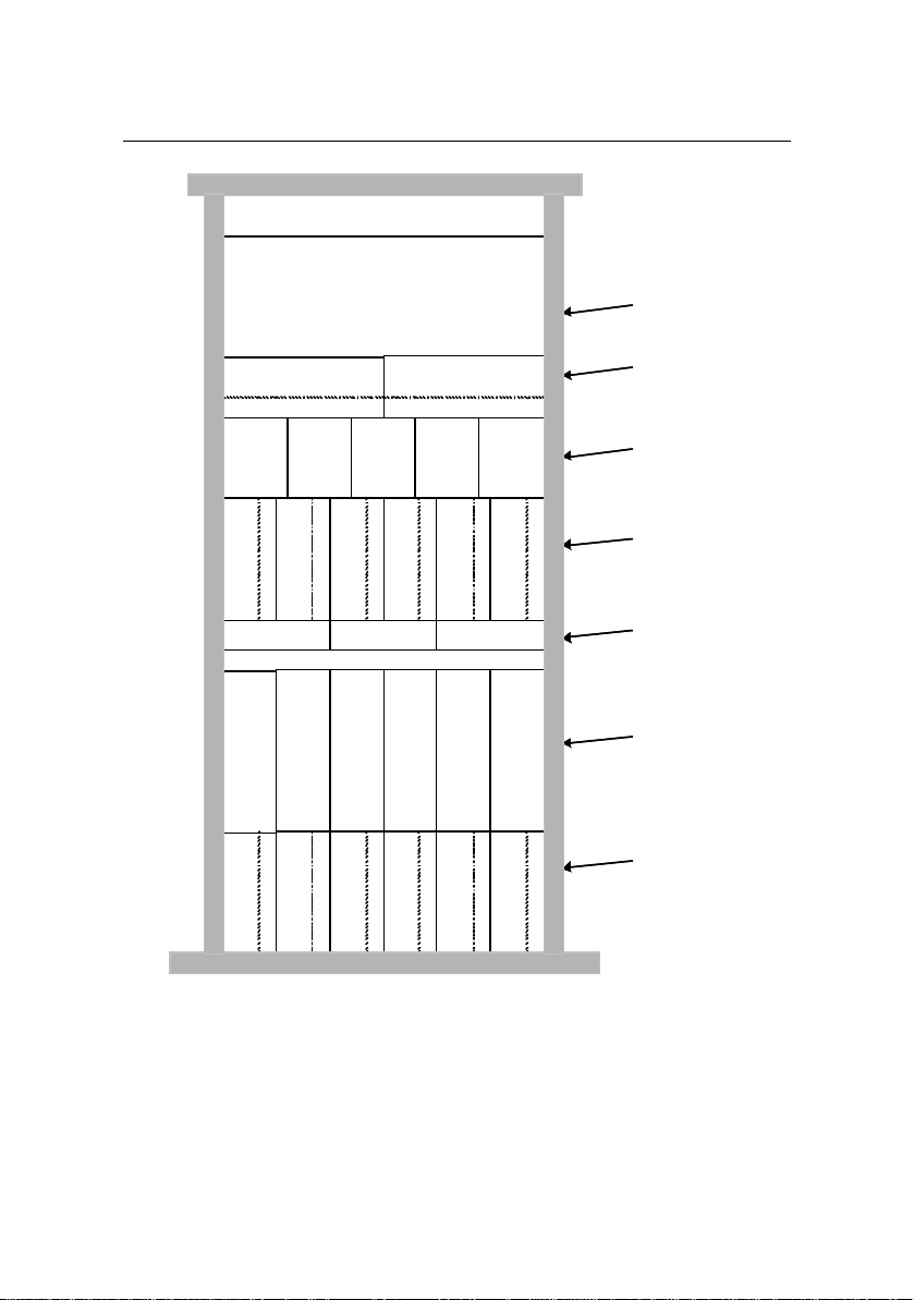
Switch Box
basebandpart is specified in Figure 2
The baseband part is specified in Figure1-2
Baseband subrack
Fan subrack
Power subrack
RF subrack
RLDU subrack
Figure 1-1 Basic cabinet configuration
1-4
CDU/DFU subrack
RF subrack

On-site Maintenance Manual
Airbridge cBTS3612 CDMA Base Station Chapter 1 Daily Maintenance
0 1 2 3 4 5 6 7 8 10 11 12 13 141516 1718 1920 219
Figure 1-2 Configuration of baseband subrack of basic cabinet
1-5

On-site Maintenance Manual
Airbridge cBTS3612 CDMA Base Station Chapter 1 Daily Maintenance
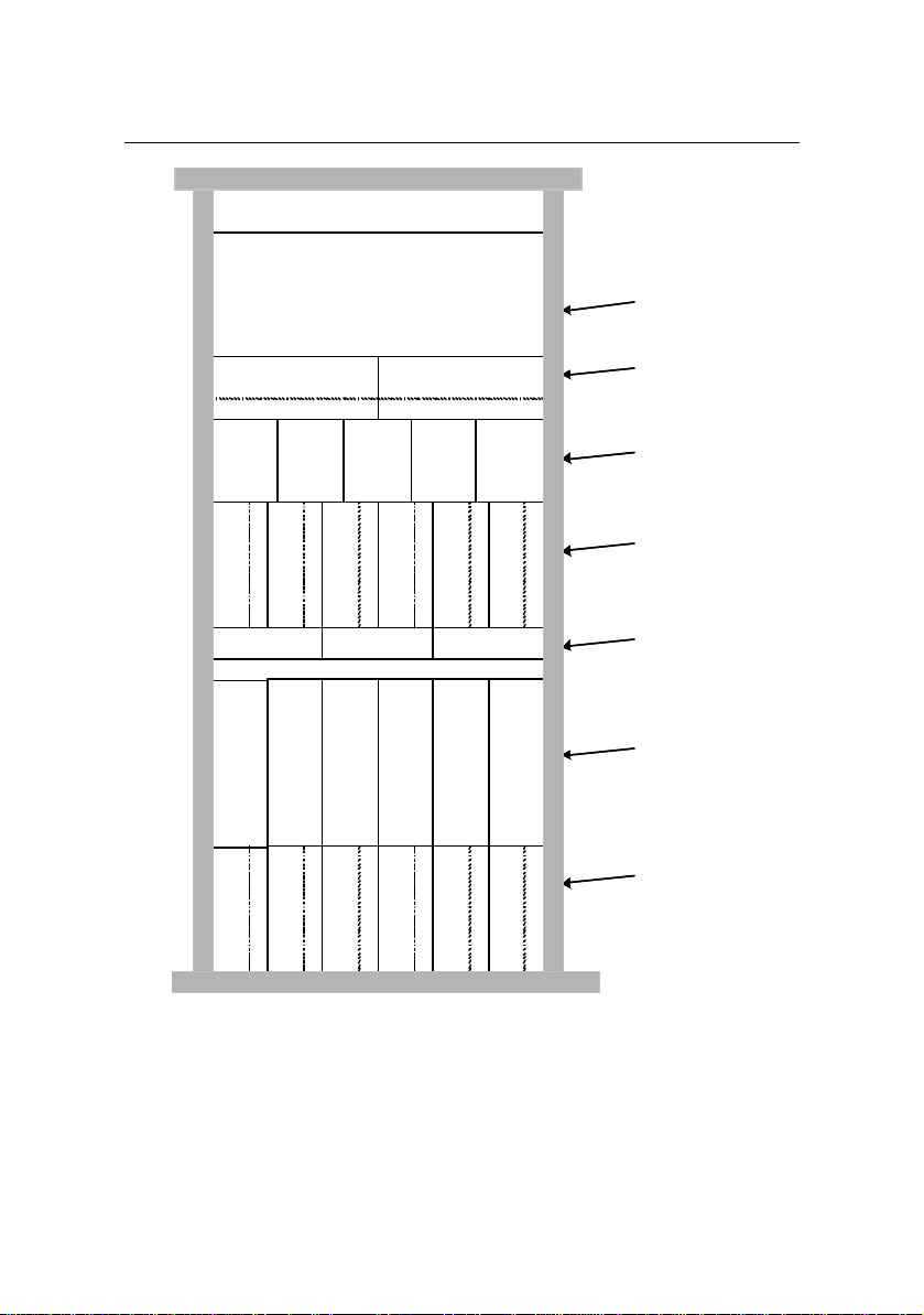
Switch Box
Thebaseband subrack of the extension cabinet
basebandpart is specified in Figure 2
has no board configuration, leave it blank.
Baseband subrack
Fan subrack
Power subrack
RF subrack
RLDU subrack
Figure 1-3 No.1 extension cabinet configuration
1-6
CDU/DFU subrack
RF subrack
On-site Maintenance Manual
Airbridge cBTS3612 CDMA Base Station Chapter 1 Daily Maintenance
Switch Box
The baseband subrack of the extension cabinet
basebandpart is specified in Figure 2
has no board configuration, leave it blank.
Baseband subrack
Fan subrack
Power subrack
RF subrack
RLDU subrack
Figure 1-4 No.2 extension cabinet configuration
1-7
CDU/DFU subrack
RF subrack

On-site Maintenance Manual
Airbridge cBTS3612 CDMA Base Station Chapter 1 Daily Maintenance
Table 1-3 Supplemental description of cabinet configuration
Item
BCIM
BRDM
BTRM
RLDU
Contents
Specify whether the DIP
switch and jumper are for
120Ù twisted pair line or for
75 Ù coaxial cable.
Specify the DIP switch and
jumper's position.
Detail the optical interface
application, for example:
which optical interfaces are
used, and their relations
(including the connection of
the BTRM of extension
cabinet with the BRDM of
the basic cabinet).
Specify the location of S/W
switch on the panel.
Remarks
1.2 Maintenance Instructions
The following steps are for your reference. Generally step 1, 2
and 3 (equipment room environment check, cabinet interior check
and dial-up test) are the basic steps required. For a thorough
maintenance, you may go through the step 4, 5 and 6 (power supply
check, lightening-proof & grounding measures and antenna and
feeder check).
1-8

On-site Maintenance Manual
Airbridge cBTS3612 CDMA Base Station Chapter 1 Daily Maintenance
I. Equipment room environment check
Table 1-4 Equipment room environment check
Items
Anti-theft
measures
Temperature
Humidity
Dust-proof
performance
Alarm
collection
device check
Check if there is any sign of burglary or
equipment damage
1. Check if the air-conditioning is
running properly.
2. Check the thermometer readings in
the equipment room (if there is no
thermometer, have one installed)
1. Check if there is any sign of water
seepage.
2. Check the humidiometer readings in
the equipment room (if there is no
humidiometer, have one installed)
1. Check if there is any visible floating
dust in the equipment room.
2. Open the cabinet door and check the
dust filter
According to the actual condition of the
alarm collection device, check the alarm
performance for access control,
temperature, humidity and smoke, etc.
Instructions
Caution-demanding issues
Temperature range: -5âC
~+50âC
Humidity range: 5%~90%.
Take measures to eliminate
the dust source, if the dust
filter has collected too many
dusts, follow the instructions
below to clean or change it.
If the above-mentioned items
are monitored by an alarm
collection device, when there
is a problem with these items
but the alarm collection
device fails to generate an
alarm on it, that device may
have run out of order. In
such case, please refer to
the relevant manuals for
proper measures to cope
with it.
1-9

On-site Maintenance Manual
Airbridge cBTS3612 CDMA Base Station Chapter 1 Daily Maintenance
II. Cabinet interior check
Table 1-5 Cabinet Interior check
Items
1. Check if the baseband subrack fan is
Fans
Board or
module
III. Dial-up test
Table 1-6 Dial-up test
running properly.
2. Check if the RF module fan is running
properly.
1. Check if the indicators of all boards and
modules are working properly.
2. Check all the RF modules and units
(including BTRM, BHPA, RLDU,
CDU/DFU/DDU): whether all the modules or
units are secured in position, screws in the
panels are properly tightened. Make sure the
panel is in a seamless contact with the front of
cabinet subrack.
Instructions
Caution-demanding
issues
1. To judge if the parts
are working properly,
refer to "Chapter 5
Component
Indicators".
2. If there is anything
wrong, please refer to
"Chapter 3
Component Failure
Handling" for advice
Items
Dial-up test
around the
base station
Driving test
1. Conduct dial-up tests on the base station in
each sector or cell.
2. During the dial-up test, move from sector to
sector and check if the handoff is successful.
3. Check the power indication of the test
mobile station, find out if the base station
power is up to the requirements.
Conduct dial-up tests within the coverage area
to test the base station covering range as well
as the handoff function.
Instructions
1-10
Caution-demanding
issues
If you come across a
problem during the
test, please refer to
"Chapter 2 General
Fault Processing " and
"Chapter 3
Component Failure
Handling".

On-site Maintenance Manual
Airbridge cBTS3612 CDMA Base Station Chapter 1 Daily Maintenance
IV. Power s upply check
Table 1-7 Power supply check
Items
Primary
Power Supply
(AC/DC)
Secondary
power supply
(PSU)
1. Use a multimeter to measure the
voltage at the power inlet.
2. Check the -48V power indicator
3. Check the indicator of lightening
arrester
1. Check on the maintenance
console if there is an alarm for
PSU.
2. Check the PSU panel indicator
Instructions
Caution-demanding issues
1. Range of input voltage: -40V ~
60V.
2. Normally the power indicators
should be on all the time.
3. Normally the indicator of
lightening arrester should be off
all the time .
1. Normally there should be no
PSU alarm
2. To judge whether the PSU is
working properly, refer to
"Chapter 5 Component
Indicators".
V. Lightening-proof and grounding check
Table 1-8 Lightening-proof and grounding check
Items
Outdoor
Indoor
1. Check if the grounding clip is connected
properly with the grounding devices (such as
an iron tower, outdoor cabling rack and
outdoor grounding bar, etc.)
2. Check if the outdoor grounding bar is
connected properly with the grounding
objects.
1. Check if the indoor equipment (such as the
cabinet-top PE grounding bar, indoor cabling
rack) are connected properly with the indoor
grounding bar.
2. Check if the indoor grounding bar is
connected properly with the grounding
objects.
Instructions
1-11
Caution-demanding issues
A multimeter can be used to
help judge if the grounding is
OK.
A multimete r can be used to
help judge if the grounding is
OK

On-site Maintenance Manual
Airbridge cBTS3612 CDMA Base Station Chapter 1 Daily Maintenance
VI. Antenna and feeder check
Table 1-9 Antenna and feeder check
Items
Antenna
and feeder
1. Check on the maintenance
console whether there is an alarm
related to the antenna and f eeder
(such as a standing wave ratio
alarm).
2. Check if the Antenna and feeder is
installed and secured properly.
3. Check if the position angle of the
directional antenna of the RF
antenna and feeder is set correctly
(If there is a directional antenna).
4. Check if the feeder connector is
damaged.
5. Check if the lightening arrester are
damaged (one is in the device box
on the antenna rack, the other is at
the GPS interface on the top of the
cabinet).
Instructions
Caution-demanding issues
1. Antenna and feeder consists
of the RF antenna and feeder
and satellite antenna and feeder .
2. For information about the
position angle of the directional
antenna, please refer to “1.1
Base Station Configuration”.
3. Whether the feeder and
connector of the RF antenna and
feeder are damaged can be
detected by the SiteMaster
4. Whether there is visible
damage to the surface of the
lightening arrester.
1-12

On-site Maintenance Manual
General Fault
Airbridge cBTS3612 CDMA Base Station
Chapter 2
Processing
Chapter 2 General Fault Processing
2.1 MS Access Network Failure
When the MS is powered on, it will go through the following
processes: system determination substate, pilot channel acquisition
substate, sync channel acquisition substate, timing change substate
and finally enter the mobile station idle state and receive the correct
system message within the specific time. Only after going through all
these processes, can the MS access the network and work properly.
2.1.1 Fault Description
The MS is unable to access the CDMA network after powered
on.
2.1.2 Troubleshooting
First make sure the MS parameters (such as basic frequency,
assistant frequency, and SID, NID etc.) have been correctly set, and
then go through the following processes one by one to locate and
eliminate problems.
I. Check if the BTS is running properly
As BTS is not running, the MS will not be able to connect to the
network. The reasons that BTS is not running could be:
2-1

On-site Maintenance Manual
General Fault
Airbridge cBTS3612 CDMA Base Station
Chapter 2
Processing
1) The BTS equipment is in a faulty condition, which will result in
the BTS start -up failure.
2) The BTS is not configured with correct parameters, which will
also result in the BTS start -up failure.
Please refer to “2.3 Base Station Initialization Failure” for fault
elimination measures.
II. Check if there is anything wrong with the Abis signaling
link
Abis signaling link failure will also result in the MS network
connection failure.
1) After the BTS start -up, if the Abis signaling link goes wrong,
BSC will be unable to perform logic configuration on BTS, which will
result in the MS network connection failure.
2) If the BTS has obtained the correct logic configuration, when
the Abis signaling link goes wrong, the BTS will turn off the
transmitting signal of the BTRM to which all its sector carrier
frequencies correspond. This will result in the MS network
connection failure.
Through querying the current alarms of the BTS on the OMC
console or BTS local maintenance console, find out if there is an
“Abis signaling link failure” alarm.
Please refer to “2.5 Abis Signaling Link Failure” for fault
elimination measures.
2-2

On-site Maintenance Manual
General Fault
Airbridge cBTS3612 CDMA Base Station
Chapter 2
Processing
III. Check if the cell has obtained the BSC logical
configuration
1) If the cell has not obtained the logic configuration, i.e.
common channels for pilot frequency, synchronization, paging
common channels, etc. has not been established or an overhead
message update has not been performed, the MS will of course not
be able to connect to the network.
Check the configuration progress report for this cell in the “BTS
status” window on the OMC console: if there is no such progress
reports as “Common channel established successfully” and
“Overhead message updated successfully”, that means the logic
configuration for this cell has not completed.
2) Sometimes the unavailability of certain physical equipment,
or some operation mistakes (such as deleting a device by mistake)
will result in the cell being deleted and the MS being unable to
connect to the network.
Check the configuration progress report for this cell in the “BTS
status” window on the OMC console: if there is a progress report
saying “Cell deleted”, that means the cell has been deleted.
If the cell has not obtained the logic configuration, we need to
verify the following items by checking the relevant indicators, board
status and alarm messages, etc.:
l Whether the BTRM used in this cell is working properly;
l Whether the BCPM used in this cell is working properly;
l Whether the corresponding BRDM is working properly;
2-3

On-site Maintenance Manual
General Fault
Airbridge cBTS3612 CDMA Base Station
l Whether the optical fiber of the BTRM and BRDM is
Chapter 2
Processing
connected properly;
l Whether the BCIM is working properly;
l Whether the Abis signaling link is working properly;
l Whether the BSC is working properly;
l Whether the parameters in the BTS and BSC are in correct
corresponding relations.
If there is a problem detected in a certain step, refer to the
relevant chapter for proper handling measures , for example, if there
is problem with the BTRM, go to “3.7 BTS Transceiver Module
(BTRM) ” for proper measures.
IV. Cell is blocked
If we can see from the OMC console that the logic configuration
for the cell has been completed, but the MS still can not connect to
the network, we can then check whether this cell has been blocked.
When a cell is blocked, the BTS will turn off the transmitting
signal of the BTRM, to which the carrier of this cell corresponds,
which will result in the MS network connection failure.
We can use command “DSP BTSBRDSTAT” to query the BTRM
status on the OMC console and find out if the BTRM to which this
cell corresponds is blocked.
If the cell is blocked, the mobile station will not be able to
connect to the network until the user unblock the cell.
2-4

On-site Maintenance Manual
General Fault
Airbridge cBTS3612 CDMA Base Station
V. Check receiving channel
Chapter 2
Processing
If we can see from the OMC console the logic configuration for
the cell has been completed, but the MS still can not connect to the
network, we can then check whether the receiving channel is
working properly.
If the BTS receiving channel is not working properly, it will result
in heavy bit errors. As a result, the MS will lose network connection
frequently. When the MS switches on, it will send a switch-on
registration message to the BTS. Due to the receiving channel failure,
the BTS is unable to receive the registration message and thus will
not send the response back to the MS, this will result in the MS
registration failure. When the registration fails, the MS will enter the
system confirmation substate and start recapturing the network,
when the network is captured, the MS will again activate the
switch-on registration… this will go on and the MS is still unable to
connect to the network.
We can use the CDMA test MS to trace the air interface
message: if the MS has sent the registration message and does not
receive the BTS response, the BTS inverse receiving channel must
be faulty.
If there is a problem with the receiving channel, we can go
through the following steps as well as checking the relevant
indicators, board status and alarm messages, etc. to locate it:
l Whether the CDU (or DFU, or DDU), RLDU and BTRM are
secured in place, or whether the panel screws are all
tightened;
l Whether the antenna and feeder is connected properly;
2-5

On-site Maintenance Manual
General Fault
Airbridge cBTS3612 CDMA Base Station
l Whether the RLDU is power on and works properly;
l Whether the RLDU panel configuration selection switch
Chapter 2
Processing
“S/W” is in the correct position. Refer to “Table 6-2
Description of RLDU switches” for details about it;
l Whether the BTRM is working properly;
l Whether the BCPM is working properly;
l Whether the BTS physical configuration is correct,
including the parameters of the cell and inverse searching
parameters, etc.
If there is a problem detected in a certain step, refer to the
relevant chapter for proper handling measures , for example, if there
is problem with the BTRM, go to “3.7 BTS Transceiver Module
(BTRM) ” for proper handling measures.
VI. Check transmitting channel
The BTRM , BHPA, CDU (or DFU, or DDU) and the antenna and
feeder constitute the transmitting channel. The malfunctioning of
transmitting channel will result in no BTS signal output or abnormal
BTS signal output. In such case, we can still find on the OMC
console that the logic configuration for the cell has been completed,
but the MS will not be able to connect to the network. We can then
go through the following steps as well as checking the relevant
indicators, board status and alarm messages, etc. to locate the
problem:
l Whether the CDU (or DFU, or DDU), BHPA and BTRM are
secured in place, or whether the panel screws are all
tightened;
2-6

On-site Maintenance Manual
General Fault
Airbridge cBTS3612 CDMA Base Station
l Whether the transmission driving component of the BTRM
Chapter 2
Processing
is working properly;
l Whether the CDU (or DFU, DDU) is working properly.
l Whether the connection between the BTRM and BHPA is
secure;
l Whether the BHPA is working properly;
l Whether the connection between the BHPA and CDU (or
DFU, DDU) is secure;
l Whether the feeder connection from the CDU (or DFU,
DDU) to the top of the cabinet is secure;
l Whether the feeder connection from the top of the cabinet
to the antenna is secure;
l Whether the blind mate in each module of the transmitting
channel are secured in place.
l Whether the antenna is installed correctly;
l Whether there is a standing wave ratio alarm;
If there is a problem detected in a certain step, refer to the
relevant chapter for proper handling measures , for example, if there
is a problem with the BTRM, go to “3.7 BTS Transceiver Module
(BTRM) ” for proper handling measures.
VII. Check cell gain & common channel gain configuration
If we can see from the OMC console the logic configuration for
the cell has been completed, but the MS still can not connect to the
network, we can then check whether the gain parameters setting is
correct when we configured the cell.
When configuring the cell, we need to configure the sector gain,
carrier gain, pilot frequency signal gain, synchronization channel gain
2-7

On-site Maintenance Manual
General Fault
Airbridge cBTS3612 CDMA Base Station
Chapter 2
Processing
and paging channel gain, etc. If these parameters are not properly
set (for example: they are set too low), the MS will not be able to
capture the common channel and thus will not be able to connect to
the network.
With the help of Abis-interface message tracing tool, find out
whether the gain parameters carried in the Abis-Cell Setup message
are correct, if not, reconfigure the BSC data configuration table.
VIII. Check overhead message
If we can see from the OMC console the logic configuration for
the cell has been completed, but the MS still can not connect to the
network, we can then check whether the overhead message is
correct.
When the MS enters the idling status, it needs to receive all the
overhead message set up by the system, which include at least the
following five:
The synchronization message, access parameter message,
system parameter message, CDMA channel list message, Neighbor
List Message. Other overhead message may vary with the network
parameter settings.
If any one of the above system messages is not received, the
MS will not be able to connect to the network.
Additionally, the value setting in each of the parameters in the
message will directly affect the MS network connection, therefore
please be careful.
2-8

On-site Maintenance Manual
General Fault
Airbridge cBTS3612 CDMA Base Station
With the help of the air interface signaling analyzer, it can be
determined whether the MS has received all the system messages.
Also, check whether the value setting in each of the parameters in
the message is correct. If not, modify the BSC parameter
configuration table and perform the overhead message update
again.
Chapter 2
Processing
2.2 Software Download Failure
2.2.1 Fault Description
Software download problems includes software download failure,
maintenance console prompting failure or there being no correct
prompt messages generated.
2.2.2 Troubleshooting
Software download failure may be caused by the following two
factors: FTP client login failure and file loading abnormally
terminated by the board.
I. FTP client login failure
1) First check if the BOOTP process of the OMU is running
properly:
The OMU requests the BTS IP address via BOOTP. If this
process fails, the BTS IP address will not be obtained, and of course
it will not be able to log in to the FTP server of BAM. Generally the
BOOTP failure may be caused by a blocked link, incorrect routing or
2-9

On-site Maintenance Manual
General Fault
Airbridge cBTS3612 CDMA Base Station
Chapter 2
Processing
configuration errors, etc. We need to locate and eliminate these
problems one by one. Refer to “ 2.4 OML Failure” for details.
2) The FTP server in the BAM is not configured correctly.
The most critical cause to such problem is the FTP server
configuration errors. The FTP server configuration includes the
following four items: username, user password, user access path
and access authority. Incorrect configuration of any of these four
items may lead to user login failure and software loading failure.
The setting of the above four items are shown below:
Username:
Password:
Access path:
Access authority: The paths for software uploading must be set as both readable and
OMU
OMU
It must include the paths specified in the software uploading and
downloading commands.
writable.
II. File loading terminated abnormally by the board
All the files should carry the correct file header in the specific
format as required. The file ID and file version in the header should
match that in the activation commands released by the OMC,
otherwise the board may consider the software to be downloaded is
not what is expected and thus prompt exceptional errors.
2-10

On-site Maintenance Manual
General Fault
Airbridge cBTS3612 CDMA Base Station
Chapter 2
2.3 Base Station Initialization Failure
Processing
2.3.1 Fault Description
When the base station is powered on, the system initialization
aborts, which leads to the BTS start -up failure.
If such problem occurs, the RUN indicators on some boards will
flash rapidly.
2.3.2 Troubleshooting
There are many causes to the BTS initialization failure, and they
can be summarized into the following aspects to help us locate them:
I. Link failure
The precondition of successful BTS initialization is the
successful establishment of ATM link between the BCIM in the BTS
and the XIE board in the BSC, i.e. the BCIM in the BTS should be
able to intercept the link configuration of the XIE board in the BSC
and establish the corresponding IMA/UNI. If the data configuration in
the BSC is incorrect (or relevant physical link is not configured), the
BCIM will not be able to intercept the link configuration and thus lead
to the link establishment failure.
What’s more, the BOOTP process failure and OML
establishment failure will also lead to the BTS initialization failure.
Please refer to “2.4 OML Failure” for details.
2-11
 Loading...