

Page 1
M72 – M73 – M 74 – M75
User manual
Copyright HT ITALIA 2013 Release EN 3.00 - 03/04/2013
Page 2

Page 3
M72 - M73 - M74 - M75
Table of contents
1. SAFETY PRECAUTIONS AND PROCEDURES ...................................................................... 2
1.1. Preliminary instructions .................................................................................................................... 2
1.2. During use ........................................................................................................................................ 3
1.3. After use ........................................................................................................................................... 3
1.4. Overvoltage categories - definitions ................................................................................................. 3
2. GENERAL DESCRIPTION ....................................................................................................... 4
2.1. Features ........................................................................................................................................... 4
2.2. TRMS value and mean value - Definitions ....................................................................................... 4
2.3. True root measn square value and crest factor - Definitions ........................................................... 4
3. PREPARATION FOR USE ....................................................................................................... 5
3.1. Preliminary checks ........................................................................................................................... 5
3.2. Power supply .................................................................................................................................... 5
3.3. Calibration ........................................................................................................................................ 5
3.4. Storage ............................................................................................................................................. 5
4. OPERATING INSTRUCTIONS ................................................................................................. 6
4.1. Instrument description ...................................................................................................................... 6
4.2. Switch on the instrument .................................................................................................................. 7
4.3. Disable Auto Power OFF.................................................................................................................. 7
4.4. Modify full scale of external transducers .......................................................................................... 7
4.5. Set minimum limit threshold on insulation measurement ................................................................. 7
4.6. HOLD, MAX/MIN/AVG, PEAK± ........................................................................................................ 8
4.6.1. HOLD ......................................................................................................................................................... 8
4.6.2. MAX/MIN/AVG ........................................................................................................................................... 8
4.6.3. PEAK± ....................................................................................................................................................... 8
4.7. V Hz: DC/AC voltage and frequency measurement .................................................................... 9
4.7.1. Anomalous cases which may occur during V Hz measurements ........................................................... 11
4.8. A Hz: DC/AC current and frequency measurement .................................................................. 12
4.8.1. Anomalous cases which may occur during A Hz measurements .......................................................... 14
4.9. : Resistance measurement and continuity test ....................................................................... 15
4.9.1. "CAL" mode ............................................................................................................................................. 15
4.9.2. Anomalous cases which may occur during measurement .............................................................. 16
4.10. : Phase sequence and phase conformity measurement ............................................................ 17
4.10.1. Anomalous cases which may occur during tests ..................................................................................... 20
4.11. LAN: Cabling test (M75) ................................................................................................................. 21
4.11.1. Anomalous cases which may occur during LAN tests .............................................................................. 22
4.11.2. SPLIT PAIRS - explication note ............................................................................................................... 22
4.11.3. Cabling errors detected by the instrument ............................................................................................... 23
4.12. 0.2A: Continuity test on earth conductors (M72, M74, M75) ....................................................... 24
4.12.1. "CAL" mode ............................................................................................................................................. 25
4.12.2. Anomalous cases which may occur during 0.2A tests ........................................................................... 27
4.13. M: Insulation measure (M72, M74, M75) ..................................................................................... 28
4.13.1. Anomalous cases which may occur during M tests ............................................................................... 29
4.14. RCD: Tests on AC type RCDs (M73, M74, M75) ........................................................................... 30
4.14.1. Anomalous cases which may occur during RCD tests ............................................................................. 31
4.15. Ra : Measurement of global earth resistance (M73, M74, M75) ................................................ 33
4.15.1. Anomalous cases which may occur during Ra tests ............................................................................ 35
4.16. AUTO: Automatic cycle of measurements (M74, M75) .................................................................. 37
5. MAINTENANCE ...................................................................................................................... 39
5.1. General ........................................................................................................................................... 39
5.2. Battery replacement ....................................................................................................................... 39
5.3. Cleaning ......................................................................................................................................... 39
5.4. End of life ....................................................................................................................................... 39
6. TECHNICAL SPECIFICATIONS ............................................................................................. 40
6.1. Reference guidelines ...................................................................................................................... 42
6.2. General specifications .................................................................................................................... 42
6.3. Environment ................................................................................................................................... 42
6.3.1. Environmental conditions ......................................................................................................................... 42
6.4. Accessories .................................................................................................................................... 42
7. SERVICE ................................................................................................................................ 43
7.1. Warranty conditions ........................................................................................................................ 43
7.2. After-sale service ............................................................................................................................ 43
EN - 1
Page 4
M72 - M73 - M74 - M75
1. SAFETY PRECAUTIONS AND PROCEDURES
This instrument complies with safety Standards IEC/EN61557-1 and IEC/EN61010-1
related to electronic measuring instruments.
CAUTION
For your own safety and to avoid damaging the instrument follow the
procedures described in this instruction manual and read carefully all notes
When taking measurements:
Avoid doing that in humid or wet places - make sure that humidity is within the limits
indicated in section “environmental conditions”. Avoid doing that in rooms where
explosive gas, combustible gas, steam or excessive dust is present
Keep you insulated from the object under test
Do not touch exposed metal parts such as test lead ends, sockets, fixing objects,
circuits etc
Avoid doing that if you notice anomalous conditions such as breakages, deformations,
fractures, leakages of battery liquid, blind display etc
Be particularly careful when measuring voltages exceeding 25V in particular places
(building yards, swimming pools, etc.) and 50V in ordinary places to avoid risks of
electrical shocks.
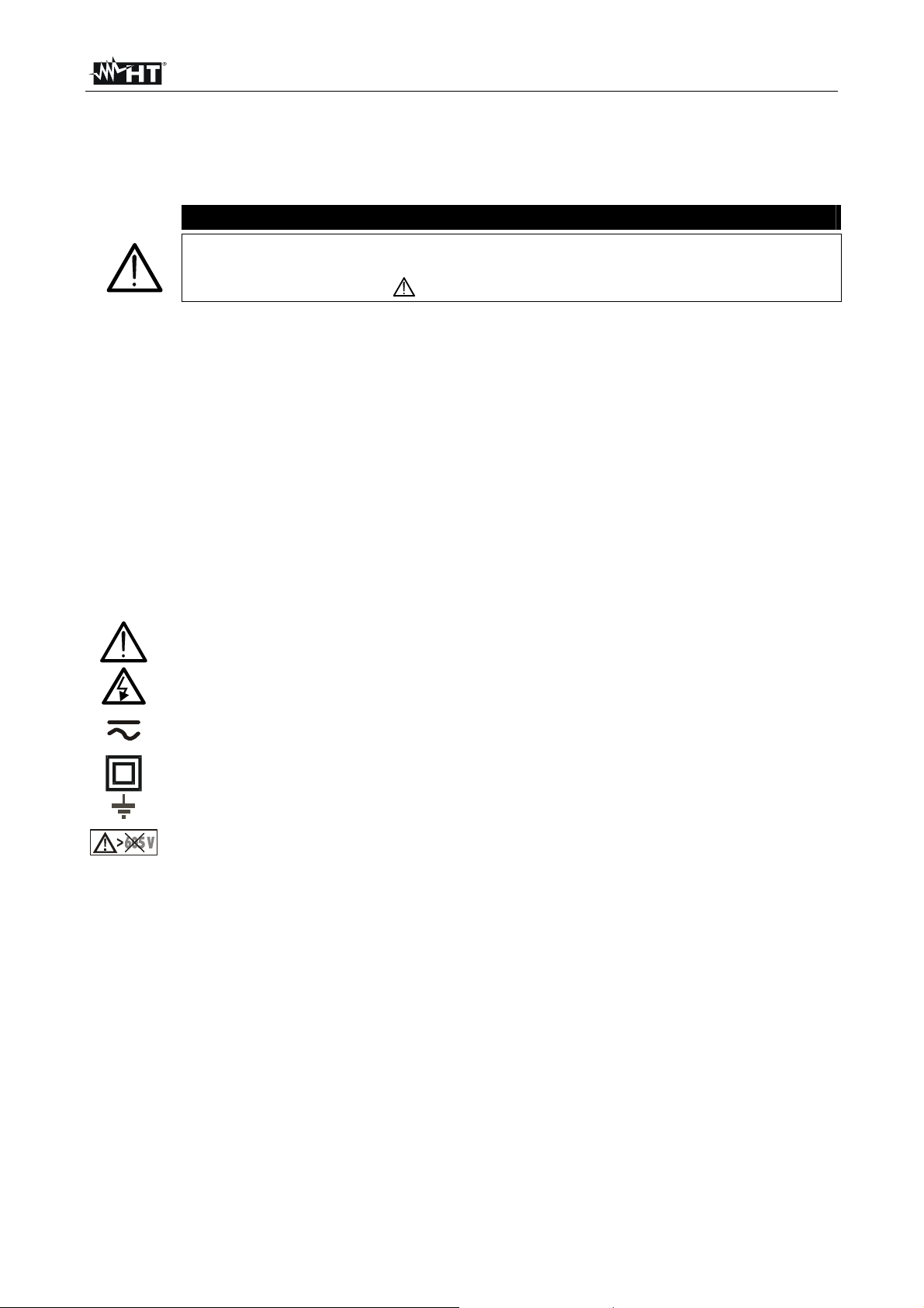
The following symbols are used:
preceded by this symbol .
CAUTION - refer to the instruction manual - an improper use may damage the
instrument or its components
CAUTION for dangerious voltage. Risk of electric shock
DC or AC voltage or current
Meter with double insulation
Ground reference
The symbol indicates that the instrument shall not be connected to systems with
rated line voltage (Phase to Phase) higher than 605V.
1.1. PRELIMINARY INSTRUCTIONS
This instrument has been designed for use in environments of pollution degree 2
It can be used for tests on electrical installations of CAT III and 550V maximum rated
interlinked voltage (and to earth)
You are recommended to respect the usual safety regulations aimed at protecting you
against dangerous currents and protecting the instrument against improper use
Only the original test leads supplied along with the instrument guarantee compliance
with the safety Standards in force. They must be in a good conditions and, if
necessary, replaced with identical ones
Do not test nor connect to any circuit exceeding the specified overload protection
Do not take measurements under environmental conditions exceeding the limits
indicated in this manual
Make sure that batteries are correctly installed
Before connecting the test probes to the installation make sure that the right function is
chosen
EN - 2
Page 5

M72 - M73 - M74 - M75
1.2. DURING USE
CAUTION
An improper use may damage the instrument and/or its components or injure
the operator.
Before selecting any function, first disconnect the test leads from the circuit under test
When the instrument is connected to circuits never touch any unused terminal
Do not measure resistance in presence of external voltages; although the instrument is
protected, an excessive voltage may cause malfunctioning.
CAUTION
If the “low battery” symbol is displayed during use interrupt testing and replace
batteries following the procedure described in § 5.2.
1.3. AFTER USE
Disconnect the test leads from the circuit under test and switch off the instrument
If you expect not to use the instrument for a long period remove batteries
1.4. OVERVOLTAGE CATEGORIES - DEFINITIONS
Standard IEC/EN61010-1 (Safety requirements for electrical equipment for measurement,
control and laboratory use, Part 1: General requirements) defines what a measurement
category (usually called “overvoltage category”) is. At § 6.7.4: Measuring circuits it says:
Circuits are divided into the following measurement categories:
Measurement category IV is for measurements performed at the source of the low-
voltage installation.
Examples are electricity meters and measurements on primary overcurrent protection
devices and ripple control units.
Measurement category III is for measurements performed in the building installation.
Examples are measurements on distribution boards, circuit breakers, wiring, including
cables, bus-bars, junction boxes, switches, socket-outlets in the fixed installation, and
equipment for industrial use and some other equipment, for example, stationary motors
with permanent connection to fixed installation.
Measurement category II is for measurements performed on circuits directly
connected to the low voltage installation.
Examples are measurements on household appliances, portable tools and similar
equipment.
Measurement category I is for measurements performed on circuits not directly
connected to MAINS.
Examples are measurements on circuits not derived from MAINS, and specially
protected (internal) MAINS-derived circuits. In the latter case, transient stresses are
variable; for that reason, the norm requires that the transient withstand capability of the
equipment is made known to the user.
EN - 3
Page 6
M72 - M73 - M74 - M75
2. GENERAL DESCRIPTION
Dear Customer, the instrument you have purchased, whether used according to the
instructions given in this manual, will grant you accurate and reliable measurements.
Thanks to a development of newest conception assuring double insulation and overvoltage
category III you will enjoy the highest safety. This manual refers to the entire range of
Multitest family including M72, M73, M74 e M75 models. Except where otherwise
expressly indicated, this manual refers to all these models.
2.1. FEATURES
V Hz: DC and AC TRMS voltage measurement, frequency measurement.
A
: measurement of resistance / continuity with sound signal
Hz: DC and AC TRMS current measurement, frequency measurement by means
of current transducer (clamp) with max. full scale of 1V.
: phase sequence detection at one or two terminals
LAN: wire mapping for cables UTP/STP in any category with connector RJ45
capable of measuring through connection to remote unit (M75).
0.2A: continuity test on earth, protective and potential equalising conductors with a
test current higher than 200mA and open voltage ranging from 4V to 24V
(M72, M74, M75)
M: insulation resistance measurement with test DC voltage of 250, 500VDC
(M72, M74, M75)
RCD: measurement on RCDs type AC (
)(M73, M74, M75)
Ra measurement of total earth resistance (M73, M74, M75)
AUTO performance of measurements in Ra , RCD and M with automatic
sequence ( M74, M75)
2.2. TRMS VALUE AND MEAN VALUE - DEFINITIONS
Safety testers for alternate quantities are divided into two categories:
MEAN VALUE instruments: instruments measuring only the value of the wave at the
fundamental frequency (50 or 60Hz).
True Root Mean Square (TRMS) instruments: instruments measuring the true root
mean square value of the quantity under test.
Mean value instruments provide only the value of the fundamental wave while TRMS
instruments provide the value of the entire wave, including harmonics (within the passband
of the instrument). Accordingly, the measured values are identical only if the wave is
purely sinusoidal.
2.3. TRUE ROOT MEASN SQUARE VALUE AND CREST FACTOR - DEFINITIONS
The current effective value is defined as follows: “In an interval of time equivalent to a
period, an alternate current with effective value having an intensity of 1A, by passing on a
resistor, disperses the same energy which would be dispersed in the same period of time
by a direct current having an intensity of 1A”. From this definition we get the numerical
Tt
expression: G=
0
1
T
The effective value is indicated as RMS (root mean square).
2
dttg
)(
t
0
The crest factor is defined as the ratio between the peak value of a signal and its effective
G
p
value: CF (G)=
sinusoidal wave it’s worth
. This value varies according to the waveform of the signal, for a purely
G
RMS
2 =1.41. In presence of distortions, the higher the wave
distortion is, the higher the crest factor values get.
EN - 4
Page 7

M72 - M73 - M74 - M75
3. PREPARATION FOR USE
3.1. PRELIMINARY CHECKS
This instrument was checked both mechanically and electrically prior to shipment. All
possible cares and precautions were taken to let you receive the instrument in perfect
conditions. Notwithstanding we suggest you to check it rapidly (eventual damages may
have occurred during transport – if so please contact the local distributor from whom you
bought the item).
Make sure that all standard accessories mentioned in § 6.4 are included.
Should you have to return back the instrument for any reason please follow the
instructions mentioned in § 7.
3.2. POWER SUPPLY
The instrument is powered by 4x1.5V batteries type AA LR6. When batteries are low, a
low battery indication " " is displayed. To replace/insert batteries follow the instructions
indicated in § 5.2.
3.3. CALIBRATION
The instrument complies with the technical specifications contained in this manual and
such compliance is guaranteed for 12 months. Annual recalibration is recommended.
3.4. STORAGE
After a period of storage in extreme environmental conditions exceeding the limits
mentioned in § 6.3.1 let the instrument resume normal measuring conditions before using
it.
EN - 5
Page 8
M72 - M73 - M74 - M75
A
4. OPERATING INSTRUCTIONS
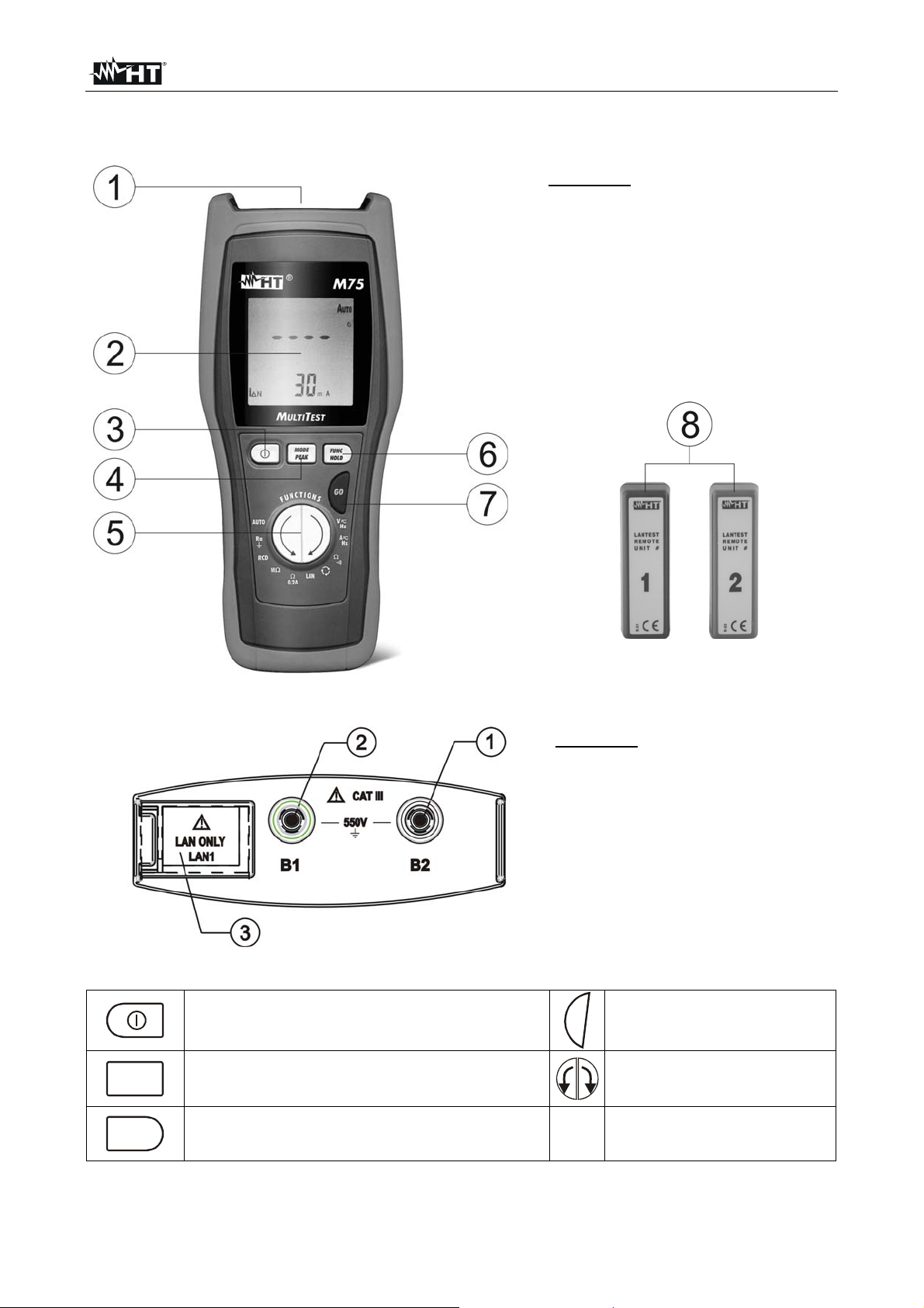
4.1. INSTRUMENT DESCRIPTION
CAPTION:
1. Inputs
2. LCD Display
3. ON/OFF key
4. MODE/PEAK key
5. Arrows key
6. FUNC/HOLD key
7. GO key
8. Remote units for LAN tests
(M75)
Fig. 1: Instrument description
CAPTION:
1. Input terminal B2
2. Input terminal B1
3. Sliding cover for RJ45
connectors of LAN networks
(M75)
Fig. 2: Instrument inputs description
GO key to start a
GO
measurement
rrow keys to select
measurements
MODE
PEAK
FUNC
HOLD
ON/OFF key To switch on/off the
instrument
MODE/PEAK key to select working mode
and to select peak measurement
FUNC/HOLD key to select internal
functions and to stop display updating
Table 1: Instrument function keys description
EN - 6
Page 9
M72 - M73 - M74 - M75
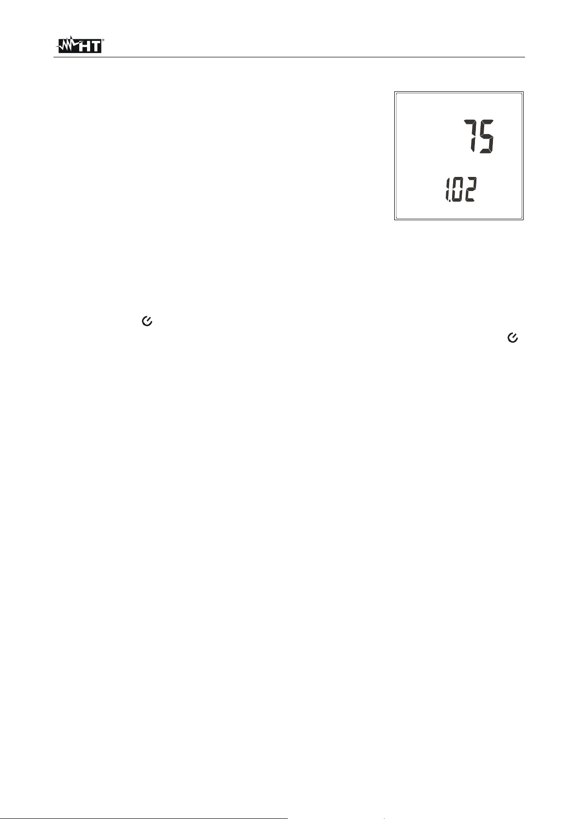
4.2. SWITCH ON THE INSTRUMENT
When the instrument is turned on, it emits a brief sound and all
display segments are lit for just one second. Then the model
number and the firmware release appear on the display (see
picture referred to M75). Finally the instrument is ready for
operation.
4.3. DISABLE AUTO POWER OFF
The instrument automatically turns off 10 minutes after last pressure of keys. To resume
operation turn on the instrument again. When the instrument must be used for long
periods, the operator may need to disable the Auto Power Off function. In order to do so:
1. Keep pressed the FUNC/HOLD key while turn on the instrument with the ON/OFF key.
The symbol “ ” disappear at display
2. On next switch on auto power off will be automatically restored and the symbol “ ”
appear at display
4.4. MODIFY FULL SCALE OF EXTERNAL TRANSDUCERS
The instrument measures AC/DC current through a clamp transducer to be connected to
the input terminals. Unlike traditional multimeters it’s therefore not necessary to interrupt
the current circuit to insert the measuring device. Besides it’s possible to use more clamps
having different full scales according to the current to be measured from time to time. To
set the full scale of the clamp being used follow the herewith steps:
1. Keep pressed the MODE/PEAK key while turn on the instrument with the ON/OFF key.
The instrument displays the “SET” message and the value of the set full scale
2. Press the arrow keys to select the desided full scale (the possible values are 1, 10, 20,
30, 100, 200, 300, 400, 1000, 2000, 3000A)
3. Press MODE/PEAK key twice to validate the modification
4.5. SET MINIMUM LIMIT THRESHOLD ON INSULATION MEASUREMENT
To set the minimum limit threshold recognized by the instrument in the insulation
measurement (see § 4.13) follow the herewith steps:
1. Keep pressed the MODE/PEAK key while turn on the instrument with the ON/OFF key.
The instrument displays the “SET” message and the value of the set full scale
2. Press the arrow keys to select the desired value (possible value are 0.25, 0.50,
1.00M)
3. Press MODE/PEAK key to validate the modification
EN - 7
Page 10

M72 - M73 - M74 - M75
4.6. HOLD, MAX/MIN/AVG, PEAK±
The following functions are available for measurements of AC and DC voltage, AC current,
frequency and resistance.
4.6.1. HOLD
The HOLD function permits to block on the display the detected value during
measurements of AC and DC voltage, AC and DC current, frequency and resistance. Just
press FUNC/HOLD for at least one second. The symbol HOLD is displayed. To escape
this function press again FUNC/HOLD or the arrow keys. This function is not available
when MAX/MIN/AVG or PEAK± functions are active.
4.6.2. MAX/MIN/AVG
During measurements of AC and DC voltage, AC and DC current, frequency and
resistance it’s possibile to measure and display the maximum (MAX), minimum (MIN) and
average (AVG) valus of the quantity under test. Press FUNC/HOLD for more than one
second to enter this function and press it repeatidly for less than one second to run
through MAX, MIN or AVG. The corresponding symbol is displayed. Maximum, minimum
and average values are detected since this function is activated and are continuously
updated even if not displayed. For example, while the AC current average value is
displayed, the maximum and minimum values of the same quantity are continuously
updated. To escape the MAX/MIN/AVG function press again FUNC/HOLD for more than
one second or the arrow keys.
The MAX/MIN/AVG function is not available when HOLD or PEAK± functions are active.
4.6.3. PEAK±
During measurements of AC and DC voltage and AC/DC current it’s possibile to measure
and display the maximum (PEAK+) and minimum (PEAK-) peak values of the quantity
under test with a resolution of 1ms. Press MODE/PEAK for more than one second to enter
this function and press it repeatidly for less than one second to run through PEAK+ or
PEAK-. The corresponding symbol is displayed.
Maximum and minimum peak values are detected since this function is activated and are
continuously updated even if not displayed. For example, while the maximum peak values
of AC current is displayed, the minimum peak value of the same quantity is continuously
updated.
When displaying maximum and minimum peaks it’s not mentioned whether the
corresponding quantity is AC or DC: a peak value is absolutely a peak value, regardless of
the quantity at which it’s detected. To escape this function press again MODE/PEAK for
more than one second or the arrow keys.
The HOLD and MAX/MIN/AVG functions are not available when when PEAK± is active.
EN - 8
Page 11
M72 - M73 - M74 - M75
4.7. V HZ: DC/AC VOLTAGE AND FREQUENCY MEASUREMENT
CAUTION
The maximum input voltage is 550+10%V. Don’t try to measure higher
voltages to avoid risks of electrical shocks or serious damages to the
instrument.
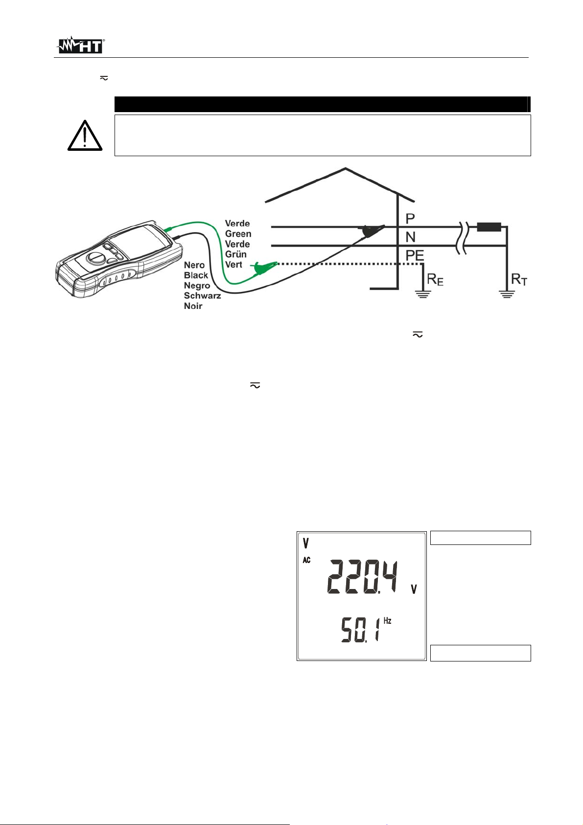
Fig. 3: Connection of the instrument’s terminals during V Hz test
1. Turn on the instrument
2. Press the arrow keys to select V Hz
3. Insert the black and green cables in the corresponding input terminals of the
instrument
4. If necessary, insert the croco clips on the test probes
5. Connect the cables to the desired points of the circuit under test as shown in Fig. 3.
The voltage and frequency values will be displayed with automatic range selection.
6. The instrument automatically switches from AC to DC voltage basing on the signal
applied to terminals.
7. Example of display of AC voltage and
AC voltage value
frequency values. The minimum reading
limit of AC voltage is 0.5V. Lower input
values are displayed as 0.0V
EN - 9
Frequency value
Page 12
M72 - M73 - M74 - M75
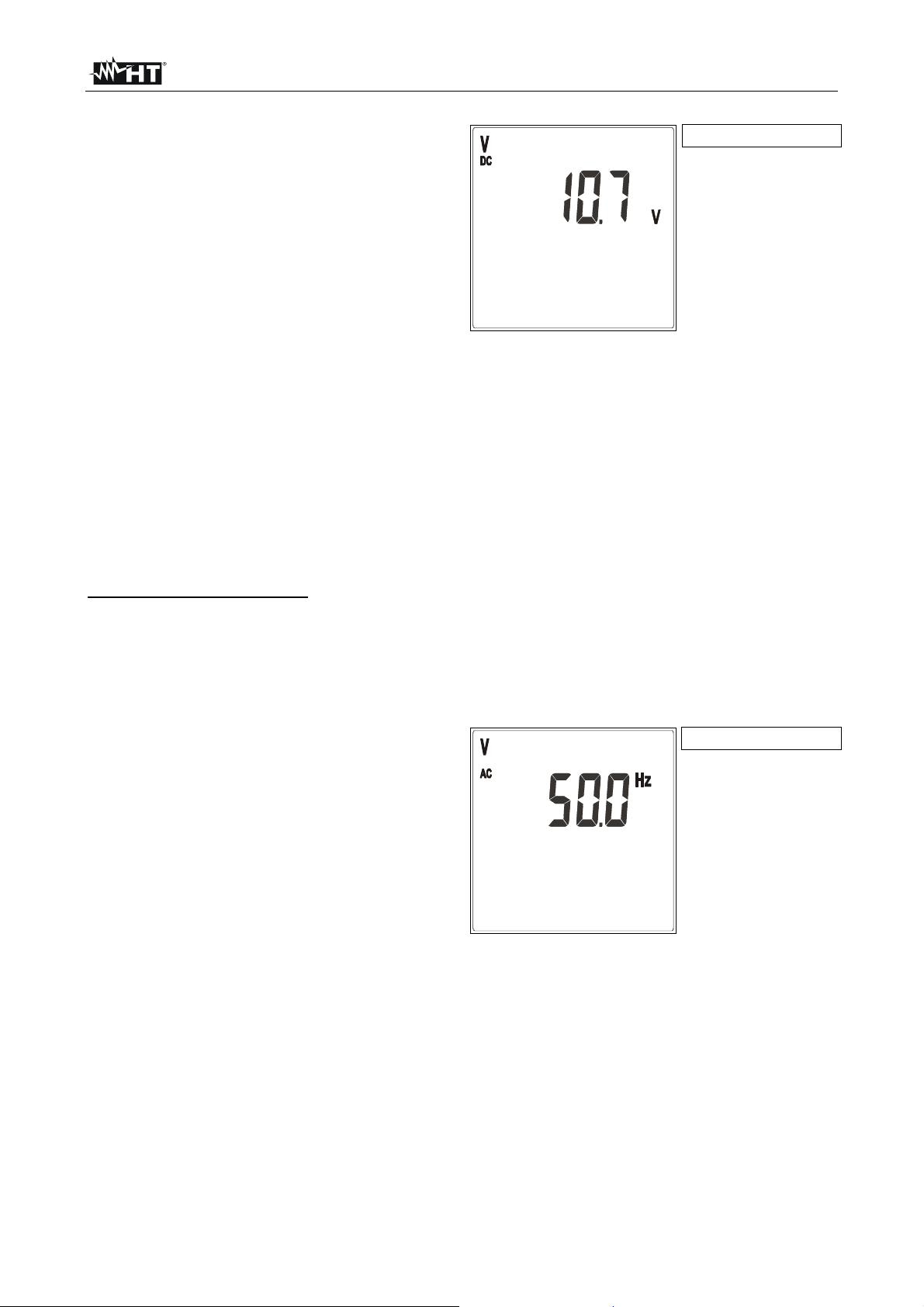
8. Example of display of DC voltage. The
DC voltage value
minimum reading limit of DC voltage is
1.2V. Lower input values are displayed
as 0.0V
9. Press MODE/PEAK for less than 1 second to pass to frequency measurement (only
during AC measurement)
10. Press MODE/PEAK for more than 1 second to detect the voltage peak value (see §
4.6.3)
11. Press FUNC/HOLD for less than 1 second to block the detected values on the display
(see § 4.6.1)
12. Press FUNC/HOLD for more than 1 second to detect maximum, minimum and
average voltage values (see § 4.6.2)
Frequency measurement
1. In order to detect minimum, average, maximum and peak values of frequency it's
necessary to pass to this measuring parameter
2. During AC measurements it’s possible to pass to frequency measurement by pressing
MODE/PEAK for less than 1 second
3. Example of display of frequency value.
Frequency value
The minimum reading limit of frequency
is 30.0Hz. Lower input values are
displayed as <30.0Hz
4. To resume voltage measurement press MODE/PEAK for less than 1 second
5. To detect the frequency peak value press MODE/PEAK for more than 1 second (see §
4.6.3)
6. To block the detected frequency value on the display press FUNC/HOLD for less than
1 second (see § 4.6.1)
7. To detect maximum, minimum and average frequency values press FUNC/HOLD for
more than 1 second (see § 4.6.2)
EN - 10
Page 13
M72 - M73 - M74 - M75
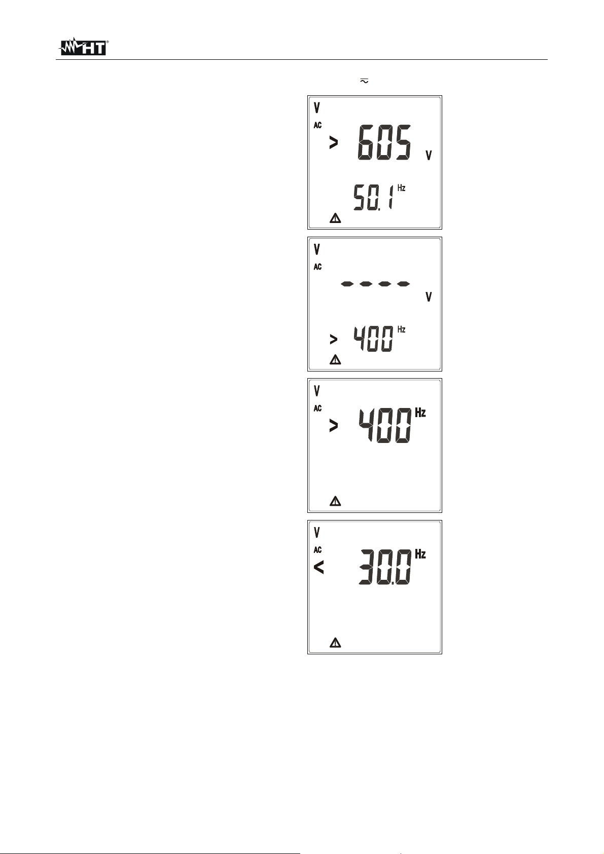
4.7.1. Anomalous cases which may occur during V Hz measurements
1. The maximum input voltage is
550+10%V.
If the detected voltage value exceeds
605V TRMS the instrument displays the
screen beside.
Disconnect immediately the instrument
from the circuit under test to avoid
electrical shocks and damages to the
instrument
2. If during a voltage measurement the
detected frequency value exceeds 400Hz
the instrument displays the screen beside
3. If during a frequency measurement the
detected value exceeds 400Hz the
instrument displays the screen beside
4. If during a frequency measurement the
detected value does not reach 30.0Hz
the instrument displays the screen beside
EN - 11
Page 14
M72 - M73 - M74 - M75
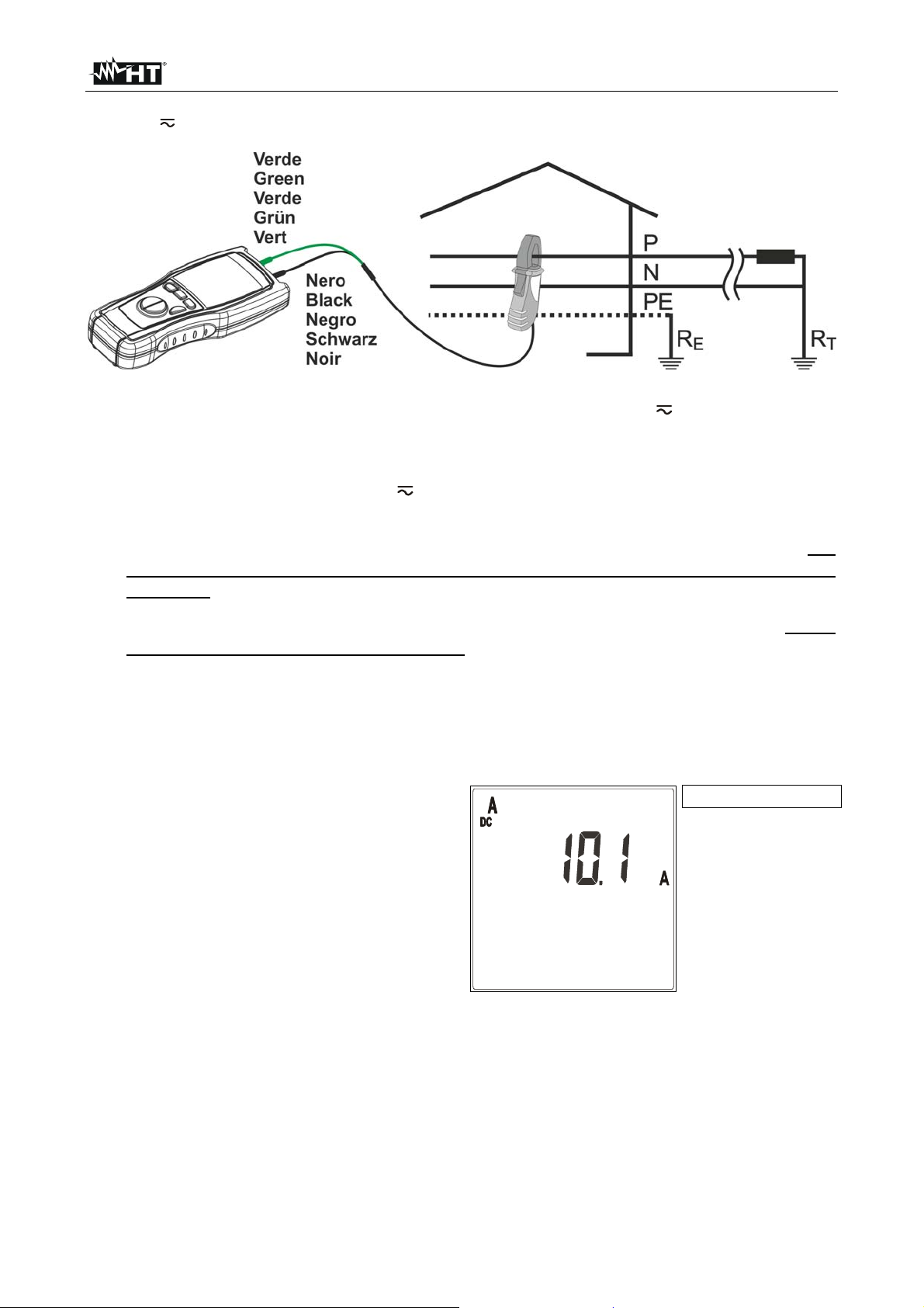
4.8. A HZ: DC/AC CURRENT AND FREQUENCY MEASUREMENT
Fig. 4: Connection of the instrument’s terminals during A Hz test
1. Turn on the instrument
2. Press the arrow keys to select A Hz
3. Insert the banana connectors of the clamp transducer in the corresponding input
terminals of the instrument (black with black, green or red with green). For
transducers with FRB hypertac connector is necessary the NOCANBA optional
accessory
4. Make sure that the clamp full scale and the instrument full scale do correspond. If they
do not, the measured value will be wrong. To set the clamp full scale refer to § 4.4
5. Open the jaws and insert the cable in the very middle as shown in Fig. 4. Current and
frequency values will be displayed
6. The instrument automatically switches from AC to DC current basing on the signal
applied to terminals
7. Example of DC current displaying. The
DC current value
minimum limit of DC current is:
1.0mV x transduction ratio of the clamp
lower values are nullified
EN - 12
Page 15
M72 - M73 - M74 - M75
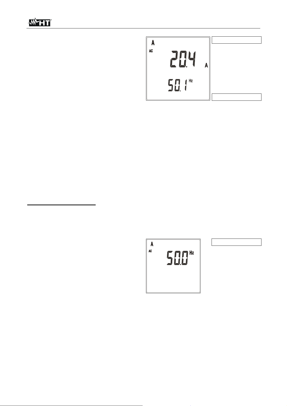
8. Example of AC current displaying. The
minimum limit of AC current is:
1.0mV x transduction ratio of the clamp
lower values are nullified.
AC current value
Frequency value
The minimum reading value of AC and DC current is given by the herewith:
1mV x transduction ratio of the clamp
Therefore, with a clamp 400A/400mV, the minimum measurable current is 1.0A.
Lower input values are displayed as 0.0A
9.
To pass to frequency measurement press MODE/PEAK for less than 1 second (only
during AC current measurements)
10. To detect the current peak value press MODE/PEAK for more than 1 second (see §
4.6.3)
11. To block the detected values on the display press FUNC/HOLD for less than 1
second (see § 4.6.1)
12. To detect maximum, minimum and average current values press FUNC/HOLD for
more than 1 second (see § 4.6.2)
Frequency measurement
1. In order to detect minimum, average, maximum and peak values of frequency it's
necessary to pass to this measuring parameter.
2. It’s possible to pass to frequency measurement by pressing MODE/PEAK for less than
1 second
3. Example of display of frequency value.
Frequency value
The minimum reading limit of frequency
is 30.0Hz. Lower input values are
displayed as <30.0Hz
4. To resume voltage measurement press MODE/PEAK for less than 1 second
5. To detect the frequency peak value press MODE/PEAK for more than 1 second (see §
4.6.3)
6. To block the detected frequency value on the display press FUNC/HOLD for less than
1 second (see § 4.6.1)
7. To detect maximum, minimum and average frequency values press FUNC/HOLD for
more than 1 second (see § 4.6.2)
EN - 13
Page 16

M72 - M73 - M74 - M75
4.8.1. Anomalous cases which may occur during A Hz measurements
1. If the detected current value exceeds the
clamp full scale the instrument displays
Example of clamp full
scale set at 400A AC
the screen beside.
Disconnect immediately the clamp from
the circuit under test to avoid electrical
shocks and damages to the instrument
The instrument is 20% overchargeable
than the clamp full scale
2. If during a current measurement the
detected frequency value exceeds 400Hz
the instrument displays the screen beside
3. If during a frequency measurement the
detected value exceeds 400Hz the
instrument displays the screen beside
4. If during a frequency measurement the
detected value does not reach 30.0Hz
the instrument displays the screen beside
EN - 14
Page 17

M72 - M73 - M74 - M75
4.9. : RESISTANCE MEASUREMENT AND CONTINUITY TEST
CAUTION
Before taking resistance measurements make sure that the circuit under test is
not powered and that eventual condensers are discharged.
Fig. 5: Connection of the instrument’s terminals
1. Turn on the instrument
2.
Press the arrow keys to select
3. If the measuring cables being used have not been calibrated, first calibrate them as
described in § 4.9.1
4. Insert the black and green cables in the
corresponding input terminals of the
instrument
5. Position the test probes on the desired
points of the circuit under test (see Fig. 5)
Resistance value
6. Example of display of resistance value. If
such value is lower than 40 the
instrument emits an acoustic signal
7. To block the detected value on the display press FUNC/HOLD for less than 1 second
(see § 4.6.1)
8. To detect maximum, minimum and average values press FUNC/HOLD for more than 1
second (see § 4.6.2)
9. The measured value is out of accuracy if an input voltage is present
4.9.1. "CAL" mode
1. Any addition or replacement of cables, extensions and croco clips nullify the previous
calibration and make necessary a new calibration before performing further
measurements. Therefore the instrument must be calibrated in the same conditions at
which it will operate during measurements
2. Short-circuit the cable ends with each other as shown in Fig. 6 making sure that the
metallic parts of test probes and crocodiles are in good touch
EN - 15
Page 18

M72 - M73 - M74 - M75
Fig. 6: Connection of the instrument’s terminals during calibration procedure
3. Press MODE/PEAK for more than 1 second. The instrument resets the resistance of
the cables, the symbol "CAL" is displayed
CAUTION
While MODE/PEAK is pressed the instrument is measuring. During this phase
never disconnect test leads.
4.
The instrument performs the calibration of cables with resistance lower than 5
5. At the end of the test the measured value is stored by the instrument and used as
OFFSET, which means it’s deducted from all continuity tests performed) for all further
measurements until a new calibration is made
6.
If the value measured during the calibration phase is higher than 5 (e.g. open
terminals) the instrument interruptus the calibration, removes the offset value
previously stored and does not display the CAL symbol until the next positive
calibration. This method can be used to nullify the last calibration performed
7. Each time the instrument is switched off the calibrated value is lost
4.9.2. Anomalous cases which may occur during measurement
1. The full scale of the instrument is
39.99k.
If the resistance value is higher than this
value, or in case of open or interrupted
probes, the instrument displays the
screen beside
EN - 16
Page 19

M72 - M73 - M74 - M75
4.10. : PHASE SEQUENCE AND PHASE CONFORMITY MEASUREMENT
CAUTION
The maximum input voltage is 550+10%V. Don’t try to measure higher
voltages to avoid risks of electrical shocks or serious damages to the
instrument. Do not use the instrument on plants whose interlinked rated
voltage is higher than 550V.
Fig. 7: Connection of the instrument’s terminals during test
1. Turn on the instrument
2.
Press the arrow keys to select
3. Press MODE/PEAK to select function “1W” (1-wire mode) or “2W” (2-wire mode)
CAUTION
1W mode requires the operator to touch the measuring key (without gloves)
and be at the earth potential, and the star centre of the system under test to be
at the earth potential. Only if these conditions are met mode 1W provides
correct results. In absence of just one of the above mentioned conditions
(operator wearing protective gloves or mounting a ladder, IT systems etc.)
select mode 2W.
4. Insert the black wire in the corresponding input terminal of the instrument. If necessary
install the croco-clip on the test probe
5. If mode 2W has been selected, insert the green wire in the corresponding input
terminal of the instrument and connect the test probe to the neutral wire or to the
neutral wire of the plant under test. If necessary install the croco-clip on the test probe
6. Following messages are displayed:
"MEASURING…" the instrument is ready to measure the first phase voltage
"PH1" (secondary display): the operator is invited to connect the measuring cable to the
cable of the L1 phase voltage (see § Fig. 7)
EN - 17
Page 20

M72 - M73 - M74 - M75
CAUTION
For a correct functioning of mode 1W it’s necessary that the star centre of the
three-phase triad under test is at the earth potential.
In plants with insulated neutral wire, like IT systems (often present in hospitals,
airports etc.) it’s necessary to select mode 2W and connect the green probe to
the neutral conductor (not to the protective conductor). In this kind of plants
mode 1W may not provide correct results.
7. Only for 1W mode press and keep pressed GO, or simply touch the surface of the key
for the entire duration of the measurement. Connect the test probe to the first wire of
the three-phase triad to be tested
8.
When a higher voltage than 110V is detected, the symbol "
PH" is displayed and the
buzzer emits a prolonged sound
CAUTION
During measurement:
GO must be always kept pressed or at least its surface must be always
touched (only for mode 1W)
The test probe, except for the phase cable under test, must not be in touch
or close to any voltage source which may block the measurement due to
the instrument’s sensitivity
The test probe must be kept in touch with the phase cable.
9. At the end of the measurement the wordings "MEASURING…" and "PH1" disappear.
The buzzer emits and intermitting sound until the test probe is disconnected drom the
phase cable
10.
Disconnect the test probe from the cable of the first phase voltage. The wording "PH"
(present only when the input voltage is detected) disappears from the display
11. Only for mode 1W keep pressed GO, or simply touch its surface, for the entire
duration of the measurement. An eventual release and new pressure on the key
cancels all performed measurements. In this case repeat all previous passages
starting from point 6
12. Following messages are displayed:
"MEASURING…" the instrument is ready to measure the second phase voltage
"PH2" (secondary display): the operator is invited to connect the measuring cable to
the cable of the L2 phase voltage (see § Fig. 7)
CAUTION
If more than 10 seconds pass between the first and the second measurement,
a message "t.out" is displayed. In this case it’s necessary to repeat the entire
procedure. Press GO and re-start from point 6.
13. Only for mode 1W keep pressed GO, or simply touch its surface, for the entire
duration of the measurement. Connect the test probe to the second cable of the threephase triad to be tested
14.
When a higher voltage than 110V is detected, the symbol "
PH" is displayed and the
buzzer emits a prolonged sound
EN - 18
Page 21

M72 - M73 - M74 - M75
CAUTION
During measurement:
GO must be always kept pressed or its surface must be always touched
(only for mode 1W)
The test probe, except for the phase cable under test, must not be in touch
or close to any voltage source which may block the measurement due to
the instrument’s sensitivity
The test probe must be kept in touch with the phase cable.
15. At the end of the test, if two tested
cables are in a correct phase sequenze,
the instrument emits a double sound to
signal the positive outcome of the test
and displays a screen like this
Correct phase
sequence
16. At the end of the test, if two cables
belong to the same phase, the
instrument emits a double sound to
sigla the positive outcome of the test
and displays a screen like this
17. At the end of the test, if two tested
cables are not in the correct phase
sequenze, the instrument emits a
prolonged sound to signal the negative
outcome of the test and displays a
screen like this
Phase rotation
Cables belonging to
the same phase
Compliance between
one cable and
another
Wrong phase
sequence
18. To perform a new measurement press GO, then re-start from point 6
CAUTION
Although two cables are in sequence it doesn’t mean that the third cable is in
sequence too. It’s not excluded that the cabling was made by mistake with a
double phase cable. To clear any possible doubt always perform at least two
measurements by testing the cables two by two.
EN - 19
Phase rotation
Page 22

M72 - M73 - M74 - M75
4.10.1. Anomalous cases which may occur during tests
1. If you wait more than 10 seconds
between the first measurement and the
second one, the instrument emits a
prolonged sound to signal the negative
outcome of the test and displays a screen
like this. It’s necessary to repeat the
entire procedure. Press GO and re-start
from point 6
2. If mode 1W is selected and the
instrument detects the connection of the
second probe like in mode 2W, a screen
like this is displayed to signal the error. A
prolonged sound is emitted until the error
condition is removed
3. If mode 2W is selected and the
instrument detects an input voltage
(between the two bushes) higher than
605V, a screen like this is displayed and
a prolonged sound is emitted until the
error condition is removed. Disconnect
the instrument promptly
EN - 20
Page 23

M72 - M73 - M74 - M75
4.11. LAN: CABLING TEST (M75)
CAUTION
Before taking any measurement make sure that the circuit under test is not
powered. Connections to phone lines or active networks could damage the
instrument.
Fig. 8: Connections of the instrument’s terminals during LAN tests
1. Turn on the instrument
2. Press the arrow keys to select LAN
3. Select the type of cable under test by pressing MODE/PEAK: set STP whether
shielded, UTP whether unshielded
4. Connect the cable under test to the instrument and to the remote unit if necessary
through patch cables (see Fig. 8)
CAUTION
The remote unit must be necessarily connected to the other end of the cable
being tested, otherwise no measurement is performed.
5. Press GO to perform all tests related to the selected type of cable
6. If cabling is correct, a screen like this is
displayed. The identification number (02)
refers to the remote unit connected to the
other end of the cable being tested
Identification number
of the remote unit
EN - 21
Page 24

M72 - M73 - M74 - M75
7. If cabling is not correct, a screen like this
is displayed (NOT OK). Referring to this
example, “FAULT 1/4” means that the
Identification number
of the remote unit (if
possible to find it)
detected errors are 4, of which the first
one is currently displayed. Details on the
detected error are given on the right side:
the couple 1-2 is open. By pressing
FUNC HOLD key it’s possible to run over
the remaining screens and display other
cabling errors (“FAULT 2/4”, “FAULT
3/4”, “FAULT 4/4”). The number of the
remote unit can be not displayed
CAUTION
Number of the
displayed error /
number of the
detected errors
It’s indispensable to select the right type of cable. If UTP is selected although
a STP cable is tested, test results may be not reliable due to the shield
affecting the measurement.
4.11.1. Anomalous cases which may occur during LAN tests
If the voltage present at the terminal is
higher 0.2V the instrument does not
perform the test and emits a sound to
signal the anomalous situation. The
screen beside is displayed.
CAUTION
Before taking any measurement make sure that the circuit under test is not
powered. Connections to phone lines or active networks could damage the
instrument.
4.11.2. SPLIT PAIRS - explication note
A LAN cable contains 8 conductors, twisted two by two thus forming 4 pairs: 1-2, 3-6,
4-5, 7-8. The error “SPLIT PAIRS” consists in the exchange of two conductors
belonging to different pairs. The pin to pin correspondence seems intact, but physically
the conductors of two couples are split. Such interaction hardly affects (or even makes
impossible) the exchange of data at high frequency/speed.
CAUTION
The error condition “SPLIT PAIRS” is verified only when the cable mapping is
fully correct. For a correct detection of such error condition it’s necessary that
the cable under test is at least 1m long.
EN - 22
Page 25

M72 - M73 - M74 - M75
4.11.3. Cabling errors detected by the instrument
Cabling errors Description Visualization Mapping
1
2
3
OPEN PAIR
One or both conductors
of the pair are interrupted
(open)
4
5
6
7
8
S
1
2
3
4
5
6
7
8
S
REVERSED PAIR
SHORTED CABLES
TRANSPOSED
(CROSSED) PAIRS
The conductors of the
same pair are reversed
Two conductors are in
short circuit between
each other
Two pairs are crossed
1
2
3
4
5
6
7
8
S
1
2
3
4
5
6
7
8
S
1
2
3
4
5
6
7
8
S
1
2
3
4
5
6
7
8
S
1
2
3
4
5
6
7
8
S
1
2
3
4
5
6
7
8
S
MISWIRE
SPLIT PAIRS
1
2
Generic cabling error,
such as for example two
conductors belonging to
different pairs are
exchanged
The pin to pin
correspondence is hold,
but physically the
conductors of two pairs
are crossed
3
4
5
6
7
8
S
1
2
3
4
5
6
7
8
S
Table 2: Possible cabling errors detected by the instrument
EN - 23
1
2
3
4
5
6
7
8
S
1
2
3
4
5
6
7
8
S
Page 26

M72 - M73 - M74 - M75
4.12. 0.2A: CONTINUITY TEST ON EARTH CONDUCTORS (M72, M74, M75)
The measurement is performed with a test current >200 mA (R<5Ω) and open circuit
voltage ranging from 4 to 24V DC according to IEC/EN61557-2 and VDE 0413 part 4.
CAUTION
Before performing the continuity test make sure that no voltage is present at the
ends of the conductor under test.
Fig. 9: Connection of the instrument’s terminals during test
1. Turn on the instrument
2.
Press the arrow keys to select 0.2A
3. Insert the black and green cables in the corresponding input terminals of the
instrument
4. If the cable length is not sufficient to perform the test, extend the black one
5. If necessary insert the croco clips on the test probes
6. If the measuring cables being used have not been calibrated, first calibrate them as
described in § 4.12.1
7. Connect the instrument’s terminals to the ends of the conductor on which the
continuità test must be performed (see Fig. 9)
8. Press GO to perform the measurement
CAUTION
The message “Measuring” on the display means that the instrument is
measuring. During this phase never disconnect test leads. Connect the
instrument just BEFORE measuring and do not change connections while the
message “Measuring” is present on the display
EN - 24
Page 27

M72 - M73 - M74 - M75
9. The continuity test is performed by supplying a current higher than 200mA if the
resistance value is lower than 5 (including the cable resistance stored as offset after
calibration). For higher resistance values the instrument performs the test with
decreasing current
10. At the end of the test, if it has been
Resistance value
possible to generate at least 200mA
(not particularly high resistance
value), the instrument emits a
double sound to signal the positive
outcome of the test. The screen
beside is displayed
11. At the end of the test, if it has not
been possible to generate 200mA
due to the high resistance value, the
instrument emits a prolonged sound
to signal the negative outcome of
the test. The screen beside is
displayed
4.12.1. "CAL" mode
Test current value
Resistance value
Test current value
Fig. 10: Connection of the instrument’s terminals during calibration procedure
EN - 25
Page 28

M72 - M73 - M74 - M75
1. By pressing MODE/PEAK select CAL
2. Any addition or replacement of cables, extensions and croco clips nullify the previous
calibration and make necessary a new calibration before performing further
measurements. Therefore the instrument must be calibrated in the same conditions at
which it will operate during measurements
3. Short-circuit the cable ends with each other as shown in Fig. 10 making sure that the
metallic parts of test probes and crocodiles are in good touch
4. Press GO to start the calibration procedure
CAUTION
The message “Measuring” on the display means that the instrument is
measuring. During this phase never disconnect test leads.
5.
The instrument performs the calibration of cables with resistance lower than 5
6. At the end of the test the measured
value is stored by the instrument and
used as OFFSET, which means it’s
deducted from all continuity tests
performed) for all further measurements
until a new calibration is made.
The instrument emits a double sound to
signal the positive outcome of the
calibration procedure and displays a
screen similar to this for 2 seconds.
Then, the default screen corresponding
to the 0.2A test is displayed
7. If the value measured during the
CAL message:
it means that the
instrument has been
calibrated. This
symbol remains
displayed during any
further measurement
even in case the
instrument is turned
off and on
Current supplied by
the instrument during
calibration procedure
calibration phase is higher than 5 the
instrument interruptus the calibration,
removes the offset value previously
stored and does not display the CAL
symbol until the next positive calibration.
The instrument emits a prolonged sound
to signal the negative outcome of the
calibration and displays a screen similar
to this for 2 seconds. Then, the default
screen related to the 0.2A test is
displayed. This method can be used to
nullify the last calibration performed
EN - 26
Page 29

M72 - M73 - M74 - M75
4.12.2. Anomalous cases which may occur during 0.2A tests
1. If the following condition occur:
R
MEASURED
- R
CALIBRATION
< -0.02
the instrument displays the screen beside
and emits a prolonged sound to signal
the anomalous situation
2. If the voltage present at the terminals is
higher than 10V the instrument does not
perform the test and emits a prolonged
sound to signal the anomalous situation.
The screen beside is displayed for 5
seconds, after which the instrument
displays the default value related to the
0.2A test
3. If the resistance value is higher than the
full scale the instrument emits a
Input voltage
prolonged sound to signal the anomalous
situation. A screen similar to this is
displayed. The same message may also
mean that mesuring cables are
disconnected or open
4.
The instrument dispalys the
CAUTION symbol with the “OK” message
when:
The instrument is operating in a
critical situation as for example in
presence of overvoltages
The instrument cannot guarantee the
measuring uncertainty lower than
30% of the reading, according to
EN61557-1
EN - 27
Page 30

M72 - M73 - M74 - M75
4.13. M: INSULATION MEASURE (M72, M74, M75)
The measurement is performed according to IEC/EN61557-2 and VDE 0413 part 1.
CAUTION
Before performing the insulation test make sure that the circuit under test is
not energized and all relative loads are disconnected.
The insulation measurement requires particolar care and attention to avoid
providing wrong test results and causing damages to third parties.
Before the insulation test prepare the plant adequately by disconnecting
everything must not be tested. During the insulation test continuously make
sure that the applied voltage is not accessible to third parties.
A measurement with a cable disconnected by mistake may provide a good
result also in presence of a faulty insulation. It’s necessary to take all
possibile cares to avoid that. Once prepared the plant and connected the
measuring cables, make sure that they are correctly connected. In case of
doubt, bifore performing an insulation test, perform a 0.2A measurement
by short-circuiting the cables under test at a point of the plant which is as
far as possibile from the measuring clips. Remove the short circuit before
performing the insulation test.
Fig. 11: Connection of the instrument’s terminals during M test
1. Turn on the instrument
2.
Press the arrow keys to select M. Select test voltage pressing MODE/PEAK key
between 250 or 500VDC. Set the value of minimum limit threshold (see § 4.5)
3. Insert the black and green cables in the corresponding input terminals of the
instrument. If the cable length is not sufficient for the measurement extend the black
one with an adequately insulated cable, as its insulation is in parallel to the resistance
to be measured. It must be suspended and not laid to earth and all supports must be of
insulated material
4. If necessary insert the croco clips on the test probes
5. Disconnect the circuit or the part of plant under test from power and all eventual loads
6. Connect the instrument’s terminals to the end of the conductors on which the insulation
test must be performed (see Fig. 11)
7. Press GO to start the measurement
EN - 28
Page 31

M72 - M73 - M74 - M75
CAUTION
The message “Measuring” on the display means that the instrument is
measuring or discharging eventual capacitors. During this phase never
disconnect nor touch test leads.
8. At the end of the test, before giving the result of the measurement, the instrument
automatically discharge eventual capacitors and parasite capacitances present
among the conductors involved in the measurement
9. At the end of the test, if the resistance
Resistance value
value is higher than the minimum limit
threshold (see § 4.5), the instrument
emits a double sound to signal the
positive outcome of the test. A screen
similar to this is displayed
10. At the end of the test, if the resistance
Test voltage value
Resistance value
value is higher than 999M, so higher
than the full scale, the instrument emits
a double sound to signal the positive
outcome of the test. A screen similar to
this is displayed. Note! An insulation
value higher than 999M is an excellent
insulation value, generally much higher
than the minimum requirements
prescribed by Standards
11. At the end of the test, if the resistance
Test voltage value
Resistance value
value is lower than the minimum limit
threshold (see § 4.5) the instrument
emits a prolonged sound to signal the
negative outcome of the test. A screen
similar to this is displayed
Test voltage value
4.13.1. Anomalous cases which may occur during M tests
If, during measurement, the voltage
present at terminals is higher than 10V
the instrument does not perform the test
and emits a prolonged sound to signal
the anomalous situation. The screen
beside is displayed for 5 seconds after
which the instrument displays the default
screen related to the M test
Input voltage value
EN - 29
Page 32

M72 - M73 - M74 - M75
4.14. RCD: TESTS ON AC TYPE RCDS (M73, M74, M75)
The test is performed in compliance with EN61008, EN61009, EN60947-2 part B 4.2.4.1,
VDE 0413 part 6 and IEC/EN61557-6
CAUTION
Testing an RCD involves the tripping of the RCD itself. Therefore, before
taking this measurement, make sure that no loads are connected to the
RCD under test to avoid damaging them
Disconnect all loads connected to the RCD as they could add further
leakage currents to those moved by the instrument, thus nullifying the test
results.
Fig. 12: Connection of the instrument’s terminals during RCD test
1. Turn on the instrument
2. Press the arrow keys to select RCD
3. By pressing MODE/PEAK select the test current among the possible values 30mA,
30mA x5, 100mA, 300mA which turn cyclically at each key pressure
CAUTION
Pay attention when setting the test current of the RCD to make sure that the
correct one is selected. In case a higher current than the nominal one of the
device under test is selected, the RCD would be tested at a higher current
than the correct one, thus favouring a quicker tripping of the RCD itself.
As an alternative:
4. Insert the black and green cables in the corresponding input terminals of the
instrument. If necessary insert the croco clips on the test probes
5. Connect the green cable to the protective conductor (earth) and the black cable to
the phase conductor at the lower end of the RCD under test (Fig. 12)
Or:
4. Insert the Shuko cable in the input terminals of the instrument
5. Insert the Shuko cable in a socket at the lower end of the RCD under test
EN - 30
Page 33

M72 - M73 - M74 - M75
6. Keep GO pressed for at least one second to perform the leakage current measurement
in phase with the positive semiwave of the network voltage (0°), or keep GO pressed
for at least one second and, when the hyphens on the display start disappearing, press
GO again to perform the measurement with the leakage current in phase with the
negative semiwave of the network voltage (180°)
CAUTION
The message “Measuring” on the display means that the instrument is
measuring. During this phase never disconnect test leads.
7. At the end of the test, if the detected
tripping time is lower than 300ms (40ms
Tripping time
for I∆n=30mA x5), the instrument emits a
double sound to signal the positive
outcome of the test and displays a screen
like this
Test current value
8. At the end of the test, if the detected
tripping time is higher than 300ms (40ms
Tripping time
exceeding the limit
for I∆n=30mA x5), or in case the RCD
does not trip, the instrument emits a
prolonged sound to signal the negative
outcome of the test and displays a screen
like this
4.14.1. Anomalous cases which may occur during RCD tests
1. If during measurement a higher input
voltage than 265V is detected (for
example, both cables connected to the
phase conductors of a 400V threephases plant) the instrument does not
perform the test and emits a prolonged
sound to signal the anomalous situation.
The screen beside is displayed for 5
seconds after which the instrument
displays the default screen of RCD test
Test current value
EN - 31
Page 34

M72 - M73 - M74 - M75
2. If during measurement a lower input
voltage than 110V is detected, the
instrument does not perform the test and
emits a prolonged sound to signal the
anomalous situation. The screen beside
is displayed for 5 seconds after which the
instrument displays the default screen of
RCD test
This can happen for example if the black cable is erroneously connected to the neutral
conductor instead of the phase one. If a Shuko cable is used, rotate the plug and
repeat the test
3. If during measurement the green probe is
connected to the phase conductor and
the black probe is connected to the
protective conductor, the instrument does
not perform the test and emits a
prolonged sound to signal the anomalous
situation. The screen beside is displayed
for 5 seconds after which the instrument
displays the default screen of RCD test
4. If during measurement an excessive
contact voltage is detected (higher than
50V) the instrument does not perform the
test and emits a prolonged sound to
signal the anomalous situation. The
screen beside is displayed for 5 seconds
after which the instrument displays the
default screen of RCD test
5. If during measurement an excessive
earth resistance is detected, such to
prevent the instrument from generatine
the test current, the instrument does not
perform the test and emits a prolonged
sound to signal the anomalous situation.
The screen beside is displayed for 5
seconds after which the instrument
shows the default screen related to RCD
test
EN - 32
Page 35

M72 - M73 - M74 - M75
4.15. RA : MEASUREMENT OF GLOBAL EARTH RESISTANCE (M73, M74, M75)
CAUTION
Disconnect all loads connected to the lower end of the RCD as they
could introduce additional leakage currents, thus nullifying the test
results.
Is possible to perform measurement on plants whose phase to earth rated
voltage is up to 265V. Do not use the instrument on plants whose
interlinked rated voltage is higher than 550V.
Fig. 13: Connection of the instrument’s terminals during test
1. Turn on the instrument
2.
Press the arrow keys to select Ra
3. By pressing MODE/PEAK select the test current among the possible values 15mA and
100mA which turn cyclically at each key pressure
CAUTION
If a RCD is present, select a lower current value than the nominal current
value of the device. Otherwise the RCD could trip during the measurement
and therefore prevent it from being executed.
4. By selecting a test current of 100mA you will get also the value of the prospective short
U
N
PE
circuit current phase to earth, calculated according to the formula ICC=
Z
where:
ZPE is the global earth resistance value
U
is the nominal phase to earth voltage whose value is: 127V if 100V ≤ V
N
230V if 150V ≤ V
measured
measured
< 150V
< 265V
As an alternative:
5. Insert the black and green cables in the corresponding input terminals of the
instrument. If necessary insert the croco climps on the test probes
6. Connect the green cable of the instrument to the protective conductor (earth)
and the black cable to the phase conductor (as shown in Fig. 13)
Or:
5. Insert the Shuko cable in the input terminals of the instruments
6. Insert the Shuko cable in a power socket (as shown in Fig. 13). The picture
represents the connection to power socket
EN - 33
Page 36

M72 - M73 - M74 - M75
7. Keep pressed GO for at least one second, the instrument performs the measurement
CAUTION
The message “Measuring” on the display means that the instrument is
measuring. During this phase never disconnect test leads.
8. At the end of the test, if the earth
resistance value is lower than 1999,
the instrument emits a double sound
and displays a screen like this reporting
the value of the measured global earth
resistance and the current at which the
measurement has been performed
Measured value of
global earth
resistance
The symbol HOLD
remains on until a
new measurement
can be taken
Current used during
the measurement
9. If a test current of 100mA has been
selected and the earth resistance value
is lower than 1999, by pressing FUNC
you will display alternatively the values
of the global earth resistance and the
prospective short circuit current phase
to earth, as well as the current at which
the measurement has been performed
Measured value of
global earth
resistance
The symbol HOLD
remains on until a
new measurement
can be taken
Current used during
the measurement
10. At the end of the test, if the global earth
resistance value is higher than 1999,
the instrument emits a double sound
Measured value of
global earth
resistance higher
than full scale
and displays a screen like this
CAUTION
To guarantee the correctness of measurements, a certain interval of time is
necessary between a measurement and the following. During this period the
symbol HOLD is displayed and no measurement can be taken. When the
symbol HOLD disappears, the instrument is ready for a new measurement.
EN - 34
The symbol HOLD
remains on until a
new measurement
can be taken
Page 37

M72 - M73 - M74 - M75
4.15.1. Anomalous cases which may occur during Ra tests
1. If during measurement the RCD
protecting the line trips, the instrument
interrupts the test and emits a prolonged
sound to signal the anomalous situation.
The screen beside is displayed for 5
seconds after which the instrument
displays the default screen of Ra test
2. If during measurement a higher input
voltage than 265V is detected (for
example, if both cables connected to
phase conductors of a 400V three-phase
plant) the instrument does not perform
the test and emits a prolonged sound to
signal the anomalous situation. The
screen beside is displayed for 5 seconds
after which the instrument displays the
default screen of Ra test
3. If during measurement a lower input
voltage than 110V is detected, the
instrument does not perform the test and
emits a prolonged sound to signal the
anomalous situation. The screen beside
is displayed for 5 seconds after which the
instrument displays the default screen of
Ra test. This can happen for example
if the black cable is erroneously
connected to the neutral conductor
instead of the phase one. If a Shuko
cable is used, rotate the plug and repeat
the test
EN - 35
Page 38

M72 - M73 - M74 - M75
4. If during measurement an excessive
contact voltage is detected (higher than
50V) the instrument does not perform the
test and emits a prolonged sound to
signal the anomalous situation. The
screen beside is displayed for 5 seconds
after which the instrument displays the
default screen of Ra
test
5.
The instrument dispalys the symbol
when:
The instrument is operating in a
critical situation as for example in
presence of overvoltages
The instrument cannot guarantee the
measuring uncertainty lower than
30% of the reading, according to
IEC/EN61557-1
6. If during measurement the green probe is
connected to the phase conductor and
the black probe is connected to the
protective conductor, the instrument does
not perform the test and emits a
prolonged sound to signal the anomalous
situation. The screen beside is displayed
for 5 seconds after which the instrument
displays the default screen of Ra
This can happen even if the wrong
test.
connection is performed on the back side
of the power socket
EN - 36
Page 39

M72 - M73 - M74 - M75
4.16. AUTO: AUTOMATIC CYCLE OF MEASUREMENTS (M74, M75)
This function permits to test an electrical plant in a completely automatic way without any
intervention of the operator.
CAUTION
Testing an RCD involves the tripping of the RCD itself. Therefore, before
taking this measurement, make sure that no loads are connected to the
RCD under test to avoid damaging them
Disconnect all loads connected to the RCD as they could add further leakage
currents to those moved by the instrument, thus nullifying the test results.
Fig. 14: Connection of the instrument’s terminals during AUTO test
1. Turn on the instrument
2. Press the arrow keys to select AUTO
3. By pressing MODE/PEAK select the test current among the possible values 30mA,
30mA x5, 100mA, 300mA which turn cyclically at each key pressure
CAUTION
Pay attention when setting the test current of the RCD to make sure that the
correct one is selected. In case a higher current than the nominal one of the
device under test is selected, the RCD would be tested at a higher current
than the correct one, thus favouring a quicker tripping of the RCD itself.
4. Insert the black and green cables in the corresponding input terminals of the
instrument. If necessary insert the alligator clips on the test probes or use the shuko
cable
5. Connect the green cable to the protective conductor (earth) and the black cable to the
phase conductor (Fig. 14) or insert the Shuko cable in a power socket
6. Keep GO pressed for at least one second, the instrument performs measurements
without any intervention of the operator in the following sequenze: Ra
(15mA), RCD,
M (phase to earth)
CAUTION
The message “Measuring” on the display means that the instrument is
measuring. During this phase never disconnect test leads.
EN - 37
Page 40

M72 - M73 - M74 - M75
7. During measurements, at the end of each test, the partial values are displayed for 5
seconds, then the instrument passes to the following test
8.
At the end of the Ra test, if the earth
resistance value is lower than 50V/I∆n
the instrument displays for 5 seconds a
screen like this, then it passes to the
Measured value of
global earth
resistance
following measurement. Refer to § 4.15
for further details or information
regarding the negative outcome of the
test or anomalous situations
9. At the end of the test, if the detected
tripping time is lower than the maximum
admittable limit, the instrument displays
Measured value of
tripping time
for 5 seconds a screen like this, then it
passes to the following screen. For
further details or information regarding
the negative outcome of the test or
anomalous situations refer to § 4.14
Value of test current
10.
At the end of the M test, if the
detected resistance value is higher than
the minimum limit threshold (see § 4.5),
Measured value of
resistance
the instrument displays for 5 seconds a
screen like this, then it passes to the
following screen. For further details or
information regarding the negative
outcome of the test or anomalous
situations refer to § 4.13
11. At the end of the AUTO test, if all tests
have a positive outcome, the instrument
emits a double sound to signal the
Value of test voltage
positive outcome and displays a screen
like this. To display partial results press
FUNC HOLD. The single test results
are dislayed cyclically by any new
pressure on this key
EN - 38
Page 41

M72 - M73 - M74 - M75
5. MAINTENANCE
5.1. GENERAL
This is a precision instrument. Strictly follow the instructions for use and storage reported
in this manual to avoid any possible damage or danger during use. Do not use this tester
under unfavorable conditions of high temperature or humidity. Do not expose to direct
sunlight. Be sure to turn off the tester after use. If the instrument is not to be used for a
long period you are recommended to remove batteries to avoid leakages of battery liquid
which may damage its internal circuits.
5.2. BATTERY REPLACEMENT
When the low battery indication " " is displayed the batteries are to be replaced.
CAUTION
Only skilled technicians can open the instrument and replace batteries. Before
removing batteries disconnect the test leads from the input terminals to avoid
electrical shocks.
1. Switch off the instrument
2. Remove test leads from the input terminals
3. Remove the battery compartment cover by using a screwdriver
4. Remove all batteries replacing them with new ones all of the same type (refer to § 6.2)
respecting the polarity signs
5. Re-allocate the battery pack taking care that the part from which the black and red
wires come out is positioned backwards
6. If the battery pack is re-allocated in a wrong way, the battery compartment can not be
closed. In this case do not force the plastic parts, but re-position the battery pack
correctly before closing
7. Replace the battery compartment cover making a pressure to close it
8. Use the appropriate battery disposal methods for your area
5.3. CLEANING
Use a soft dry cloth to clean the instrument. Never use wet cloths, solvents, water, etc.
5.4. END OF LIFE
Caution: this symbol indicates that equipment and its accessories shall be
subject to a separate collection and correct disposal
EN - 39
Page 42

M72 - M73 - M74 - M75
6. TECHNICAL SPECIFICATIONS
Accuracy is indicated as [%reading + (digit number*resolution)] at: 23°C±5°C, <70%HR.
DC/AC TRMS Voltage
Range Resolution
1.0 999.9mV
1.000 9.999V
10.00 99.99V
100.0 605.0V
MAX, MIN, AVG, PEAK, resolution: (5.0% rdg + 10 dgt); responce time: 500ms (MAX, MIN, AVG),1ms (PEAK)
Max crest factor: 3.0: V<1.0V; 1.5: V≥1.0V
0.1mV
0.001V
0.01V
0.1V
Accuracy
DC
(0.5rdg+2dgt) (1.0rdg+2dgt) (2.0rdg+2dgt) 1M
Accuracy
(30 70Hz)
DC/AC TRMS Current (with external jaws)
Range Resolution
1.0 999.9mV
1.000 1.200V
NOTE The mentioned accuracy does not consider the transducer's accuracy. Please refer to its user's manual
MAX, MIN, AVG, PEAK, resolution: (5.0% rdg + 10 dgt); responce time: 500ms (MAX, MIN, AVG),1ms (PEAK)
Minimum input current: 1mV x transduction ratio of the clamp
Max crest factor: 3.0: V<1.0V; 1.5: V≥1.0V
0.1mV
0.001V
Accuracy
DC
(0.5rdg+
2dgt)
Accuracy
(30 70Hz)
(1.0 rdg +
2 dgt)
Accuracy
(70 400Hz)
(2.0 rdg +
2 dgt)
Frequency measurement with test leads
Ra nge Res olutio n Ac curacy Input impedance
30.0 199.9Hz
200 400Hz
Input voltage: 1mV 605.0V
0.1Hz
1Hz
(0.5rdg + 2dgt) 1M
Frequency measurement with jaws
Range Resolution Accuracy Overload protection
30.0 199.9Hz
200 400Hz
Input voltage: 1mV 1V
0.1Hz
1Hz
(0.5rdg + 2dgt)
Resistance and continuity test
Range Resolution Accuracy Buzzer Overload protection
0.00 39.99 0.01
40.0 399.9 0.1
400 3999 1
(1.0%rdg + 5dgt) R<40
4.00 39.99 k 10
Phase sequence and phase conformity
Measuring method Working voltage (V) System
1 test lead (1W)
2 test leads (2W)
Max crest factor: 1.5 ; Frequency range: 45 65 Hz
(*) The two-wire measurement can be performed also phase to phase in plants without neutral, even with one phase to earth, but
always with phase to phase voltage up to 550V
90 315 (Phase - Ground)
90 315 (Phase - Neutral)
0.2A: Continuity with 200mA (M72, M74, M75)
Range Resolution Accuracy Overload protection
0.00 19.99 0.01
< 24V
0
0.1
20.0 99.9
Test current: >200mA DC up to 5 (measuring cables resistance included)
Accuracy of current measurement: 1mA
Open circuit voltage: 4 < V
(5.0% rdg + 3 dgt)
Accuracy
(70 400Hz)
Input
impedance
1M
Input
impedance
Overload
protection
605V AC
max RMS
605V AC max RMS
605V AC max RMS for 1 minute
up to 315 V (Phase - Ground)
up to 550V (Phase - Phase)
up to 315 V (Phase - Neutral)
up to 550V (Phase - Phase) (*)
605V max RMS
EN - 40
Page 43

M72 - M73 - M74 - M75
M: Insulation resistance 250, 500VDC (M72, M74, M75)
Range Resolution Accuracy Overload protection
0.00 19.99M 0.01M
20.0 199.9M 0.1M
200 999M(*) 1M
(*) For 500VDC test voltage. For 250VDC test voltage the range is: 200 499M
Autorange
Open circuit voltage: <1.3 x V
Accuracy of nominal voltage: –0% +10%
Short circuit current: <3.0mA
Nominal testing current: 1mA @ 1K x V (1mA @ 500K)
0
(5.0% rdg + 2 dgt)
(5.0% rdg + 2 dgt)
(10.0% rdg + 2 dgt)
605V max RMS
RCD: test on RCD devices AC type (M73, M74, M75)
Range Resolution Accuracy Overload protection
2 400ms
Phase to ground voltage: 110 265V
Test currents: 30mA, 30mA x 5, 100mA, 300mA
Frequency: 50Hz 0.5Hz / 60Hz 0.5Hz
1ms
(2.0% rdg + 2 dgt)
605V max RMS
Ra : Measurement of global earth resistance (M73, M74, M75)
Test current Range Resolution Accuracy Overload protection
15mA
100mA
Phase to ground voltage: 110 265V; Frequency: 50Hz 0.5Hz / 60Hz 0.5Hz
Nominal voltage used for the calculation of the prospective short circuit current: 127V if 100V ≤ V
230V if 150V ≤ V
1 1999 1
0.1 199.9 0.1
(5% rdg + 2 dgt)
(5% rdg + 3 dgt)
605V max RMS
< 150V
measured
< 265V
measured
Wire mapping (M75)
Length of the cable: 1100m
Number of remote units: max 8 units
Detected errors: OPEN Pairs, REVERSED pairs, SHORT pairs, SPLIT pairs, CROSSED pairs, MISWIRING
According to the norm: TIA568B
CAUTION
In all measurements the instrument dispalys the symbol when:
The instrument is operating in a critical situation as for example in
presence of overvoltages.
The instrument cannot guarantee the measuring uncertainty lower than
30% of the reading, according to IEC/EN61557-1.
EN - 41
Page 44

M72 - M73 - M74 - M75
6.1. REFERENCE GUIDELINES
Safety: IEC/EN61010-1, IEC/EN61557-1-2-3-4-6-7
Insulation: double insulation
Pollution level: 2
Measurement category: CAT III 550V (phase to earth, phase to phase)
Maximum height of use: 2000m ; (6562ft)
LAN test TIA568B
6.2. GENERAL SPECIFICATIONS
Electrical features
Conversion: ADC 16 bit, TRMS – True Root Mean Square
Measuring rate: 64 times per second
Display refreshing rate: 2 times per second
Mechanical features
Dimensions (L x W x H): 240 x 100 x 45mm ; (9 x 4 x 2in)
Weight (batteries included): 630g ; (22ounces)
Power supply
Battery type: 4x1.5V batteries type AA LR6 MN 1500
Low battery indication: symbol " " is displayed
Battery life: Multimeter: About 90 hours
: > 1000 tests
LAN: > 1000 tests
0.2A: > 1000 tests @ 1
M: > 1000 tests @ 480k (500VDC)
RCD: > 1000 tests
Ra : > 1000 tests
AUTO: > 1000 tests
Display
Features: 4 LCD with max. reading 9999 counts + symbol
and decimal point
6.3. ENVIRONMENT
6.3.1. Environmental conditions
Reference temperature: 23°C ± 5°C ; (73°F ± 41°F)
Working temperature: 0°C ÷ 40 °C ; (32°F ÷ 104°F)
Relative humidity allowed: <70%HR
Storage temperature: -10 ÷ 60 °C ; (14°F ÷ 140°F)
Storage humidity: <70%HR
This instrument complies with the requirements of the European Low Voltage
Directive 2006/95/CE (LVD) and EMC Directive 2004/108/CE
6.4. ACCESSORIES
Please see enclosed packing list.
EN - 42
Page 45

M72 - M73 - M74 - M75
7. SERVICE
7.1. WARRANTY CONDITIONS
This instrument is guaranteed against material or manufacturing defects, in accordance
with general sales conditions. During the warranty period the manufacturer reserves the
right to decide either to repair or replace the product.
Should you need for any reason to return back the instrument for repair or replacement
take prior agreements with your local distributor. Freight charges are up to the customer.
Do not forget to enclose a report describing the reasons for returning the unit as well as
the detected fault.
Use only original packaging. Any damage occurred in transit due to no-original packaging
will be charged anyhow to the customer.
The manufacturer will not be responsible for any damage to persons or things.
The warranty doesn’t apply to the following cases:
Repair and/or replacement of accessories and batteries (not covered by warranty)
Repairs made necessary due to improper use (including adaptation to particular
applications not foreseen in the instructions manual) or improper combination with
incompatible accessories or equipment
Repairs made necessary due to improper shipping material causing damages in transit
Repairs made necessary due to previous attempts for repair carried out by unskilled or
unauthorized personnel
Instruments for whatever reason modified by the customer himself without explicit
authorization of our Technical Dept
Use not provided by the instrument's specifications or in the instruction manual.
The contents of this manual may not be duplicated in any form whatsoever without the
manufacturer’s authorization.
Our products are patented and our logotypes registered. We reserve the right to
modify specifications and prices in view of technological improvements or
developments which might be necessary.
7.2. AFTER-SALE SERVICE
Shouldn’t the instrument work properly, before contacting your distributor make sure that
batteries are correctly installed and working, check the test leads and replace them if
necessary. Make sure that your operating procedure corresponds to the one described in
this manual.
Should you need for any reason to return back the instrument for repair or replacement
take prior agreements with the local distributor from whom you bought it. Do not forget to
enclose a report describing the reasons for returning (detected fault). Use only original
packaging. Any damage occurred in transit due to non original packaging will be charged
anyhow to the customer.
The manufacturer will not be responsible for any damage to persons or things.
EN - 43
Page 46

Page 47

Page 48

YAMUM0026HT0
Via della Boaria 40
48018 – Faenza (RA) - Italy
Tel: +39-0546-621002 (4 linee r.a.)
Fax: +39-0546-621144
email: ht@htitalia.it
Web: www.ht-instruments.com
 Loading...