

Page 1
THT70
User manual
Copyright HT ITALIA 2014 Release 1.01 - 03/03/2014
Page 2

Page 3

THT70
Table of contents:
1 PRECAUTIONS AND SAFETY MEASURES ........................................................................... 3
1.1 During use ........................................................................................................................................ 3
1.2 After use ........................................................................................................................................... 3
2 GENERAL DESCRIPTION ....................................................................................................... 4
3 PREPARATION FOR USE ....................................................................................................... 5
3.1 Initial checks ..................................................................................................................................... 5
3.2 Instrument power supply .................................................................................................................. 5
3.3 Calibration ........................................................................................................................................ 5
3.4 Storage ............................................................................................................................................. 5
4 NOMENCLATURE .................................................................................................................... 6
4.1 Instrument description ...................................................................................................................... 6
4.2 Description of function keys ............................................................................................................. 9
4.2.1 Switching on/off the instrument .......................................................................................................... 9
4.2.2 Key ................................................................................................................................................ 9
4.2.3 Key ............................................................................................................................................... 9
4.2.4 Key ............................................................................................................................................... 9
4.2.5 Key ............................................................................................................................................. 10
4.2.6 T key (Trigger) ................................................................................................................................. 10
5 OPERATING INSTRUCTIONS ............................................................................................... 11
5.1 Description of the main interface .................................................................................................... 11
5.1.1 Image focusing ................................................................................................................................ 11
5.1.2 Image rotation and zoom ................................................................................................................. 12
5.1.3 Adjusting the distance of the object in Fusion screens .................................................................... 12
5.2 Main menu description ................................................................................................................... 13
5.2.1 Settings Menu .................................................................................................................................. 13
5.2.1.1 “General” section......................................................................................................................................... 13
5.2.1.2 “Control” section .......................................................................................................................................... 14
5.2.1.3 “Images” section .......................................................................................................................................... 17
5.2.1.4 “Date/Time” section ..................................................................................................................................... 18
5.2.1.5 “Information” section ................................................................................................................................... 18
5.2.2 Measure Menu ................................................................................................................................. 19
5.2.2.1 Setting of measuring cursors ...................................................................................................................... 19
5.2.2.2 Setting of Measuring lines ........................................................................................................................... 21
5.2.2.3 Setting of measuring areas ......................................................................................................................... 23
5.2.2.4 Setting the Measure Menu .......................................................................................................................... 25
5.2.2.5 Control parameters of temperature measurement ..................................................................................... 28
5.2.3 Image menu ..................................................................................................................................... 30
5.2.3.1 Setting the display type ............................................................................................................................... 30
5.2.3.2 Setting the colour palette ............................................................................................................................ 32
5.2.3.3 Adjusting the image temperature ................................................................................................................ 35
5.2.3.4 Setting the Isotherm function ...................................................................................................................... 37
5.2.4 Camera menu .................................................................................................................................. 38
5.2.4.1 Fixing the image on the display and saving ................................................................................................ 38
5.2.4.2 Voice annotation ......................................................................................................................................... 39
5.2.4.3 Text annotation ........................................................................................................................................... 40
5.2.4.4 Recording IR videos .................................................................................................................................... 40
5.2.5 Gallery menu ................................................................................................................................... 41
5.2.5.1 Deleting images .......................................................................................................................................... 42
5.2.6 Video menu ...................................................................................................................................... 43
5.2.6.1 Deleting IR videos ....................................................................................................................................... 43
5.3 Using the instrument ...................................................................................................................... 44
5.4 Transferring IR images/videos onto the PC ................................................................................... 46
5.5 Video output ................................................................................................................................... 46
6 USING THE THTLINK SOFTWARE ....................................................................................... 47
6.1 Minimum system requirements ...................................................................................................... 47
6.2 Installing the THTLink software ...................................................................................................... 47
6.3 Main characteristics of the THTLink software ................................................................................ 47
7 MAINTENANCE ...................................................................................................................... 48
7.1 General information ........................................................................................................................ 48
7.2 Recharging the internal battery ...................................................................................................... 48
7.2.1 Recharging the battery with direct connection to the electric mains ................................................ 48
7.2.2 Recharging by connection to the recharging base .......................................................................... 49
7.3 Cleaning the instrument ................................................................................................................. 49
EN - 1
Page 4

THT70
7.4 End of life ....................................................................................................................................... 49
7.5 Accessories .................................................................................................................................... 49
7.5.1 Accessories provided ....................................................................................................................... 49
7.5.2 Optional accessories ....................................................................................................................... 49
8 TECHNICAL SPECIFICATIONS ............................................................................................. 50
8.1 Environment ................................................................................................................................... 50
8.1.1 Environmental conditions for use ..................................................................................................... 50
9 SERVICE ................................................................................................................................ 51
9.1 Warranty conditions ........................................................................................................................ 51
9.2 Service ........................................................................................................................................... 51
EN - 2
Page 5
THT70
1 PRECAUTIONS AND SAFETY MEASURES
The instrument has been designed in compliance with the directives relevant to electronic
measuring instruments. For your safety and in order to prevent damaging the instrument,
please carefully follow the procedures described in this manual and read all notes
preceded by the symbol with the utmost attention. Before and after carrying out the
measurements, carefully observe the following instructions:
Do not carry out any measurements in case gas, explosive materials or
flammables are present, or in humid or dusty environments.
Do not carry out any measurement in case you find anomalies in the
instrument such as deformation, breaks, substance leaks, absence of
display on the screen, etc.
Keep the instrument steady during any measuring operation.
Do not carry out any measurements which exceed the working and storage
temperature ranges specified in § 8.1.1.
Only the accessories provided together with the instrument will guarantee
safety standards. They must be used only if in good conditions and
replaced with identical models, when necessary.
Check that the battery is correctly inserted.
Check that the LCD display gives indications consistent with the function
selected.
Do not direct the instrument at very high intensity radiation sources (e.g. the
sun) in order to prevent damaging the IR sensor.
Prevent hits or strong vibrations in order to keep the instrument from
damage.
When bringing the instrument from a cold to a hot environment, leave it on
long enough for condensation water to evaporate.
In this manual, and on the instrument, the following symbols are used:
Only use the micro SD card provided with the instrument.
Caution: observe the instructions given in this manual; improper use could
damage the instrument or its components.
This symbol on the display means that the instrument is able to emit a laser
pointer in Class 2. Do not direct the radiation towards the eyes in order to
prevent physical damage to people.
CAUTION
Compliant with European Standards
1.1 DURING USE
CAUTION
Failure to comply with the caution notes and/or instructions may damage
the instrument and/or its components or be a source of danger for the
operator.
Use the instrument only in the temperature ranges indicated in this manual.
1.2 AFTER USE
When measurement is complete, switch off the instrument. If you expect not to use the
instrument for a long period, remove the battery.
EN - 3
Page 6

THT70
2 GENERAL DESCRIPTION
The instrument is a professional digital thermal camera capable of carrying out infrared
temperature measurements of objects and providing high-resolution images in an
extremely flexible way. It is also very easy to use and needs little maintenance.
The main characteristics of the instrument are:
Infrared temperature measurement ranging from -20°C to 400°C
Built-in photo camera for visible image
Fusion PiP function
3 selectable measuring cursors
TFT colour display with capacitive touch-screen
Alarm conditions on temperature measurement
Table with emissivity values of common material
8 standard colour palettes
10 custom colour palettes
Electronic zoom x1-x20
Advanced analyses (Spots, Lines, Areas, Isotherm)
Automatic detection of hot/cold spots of the image
Storage of JPG images on external micro SD card
IR sensor resolution: 384x288pxl
USB port for PC connection and image transfer
Voice and text annotations
IR MPEG4 video recording on micro SD card
Video and microphone output
Built-in laser pointer and illuminator
Rechargeable Li-ION battery
Analysis and printing of images with the dedicated software provided
The applications of the digital thermal camera are:
Predictive and preventive maintenance of the electrical and mechanical appliances
Monitoring of the temperature of working processes
Maintenance and troubleshooting on forced ventilation ducts
Domestic/industrial use in troubleshooting environmental insulation problems
Applications in the construction field
Safety problems
EN - 4
Page 7

THT70
3 PREPARATION FOR USE
3.1 INITIAL CHECKS
Before shipping, the instrument has been checked from an electric as well as mechanical
point of view. All possible precautions have been taken so that it is delivered undamaged.
However, we recommend generally checking the instrument in order to detect possible
damage suffered during transport. In case anomalies are found, immediately contact the
forwarding agent.
We also recommend checking that the packaging contains all components indicated in §
7.5. In case of discrepancy, please contact the Dealer. In case the instrument should be
replaced, please carefully follow the instructions given in §. 9
3.2 INSTRUMENT POWER SUPPLY
The instrument is supplied by a 1x7.4V rechargeable Li-ION battery and AC mains power
supply, which also provides for the recharge of the mentioned battery. Both of these
systems are provided with the instrument. For battery recharge, please refer to § 7.2.
3.3 CALIBRATION
The instrument has the technical specifications described in this manual. The instruments
performance is guaranteed for one year.
3.4 STORAGE
In order to guarantee precise measurement, after a long storage time under extreme
environmental conditions, wait for the instrument to come back to normal condition (see §
8.1.1).
EN - 5
Page 8
THT70
4 NOMENCLATURE
4.1 INSTRUMENT DESCRIPTION
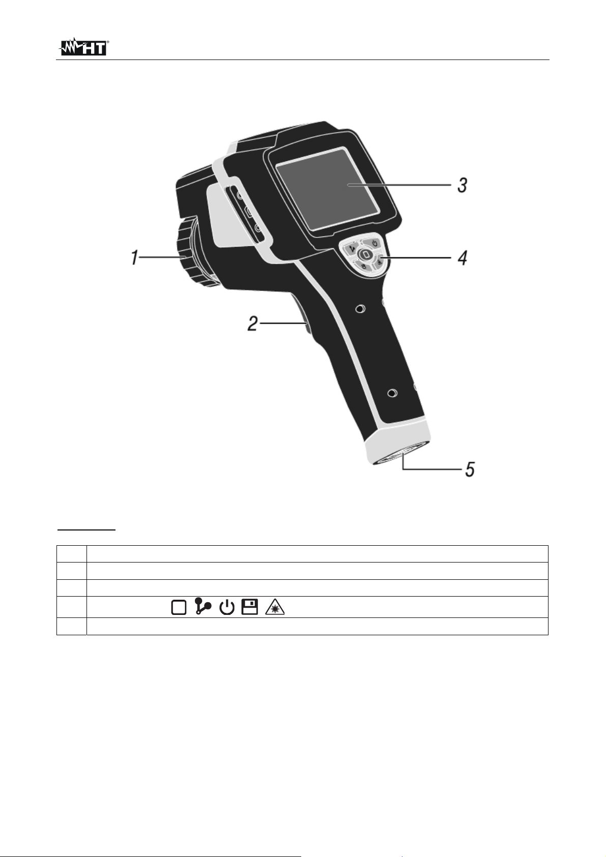
Fig. 1: Description of the instrument's backside
CAPTION:
1 Lens associated with the IR sensor
2 Trigger key (T)
3 LCD touch-screen display
4
Function keys , , , ,
5 Battery compartment cover
EN - 6
Page 9
THT70
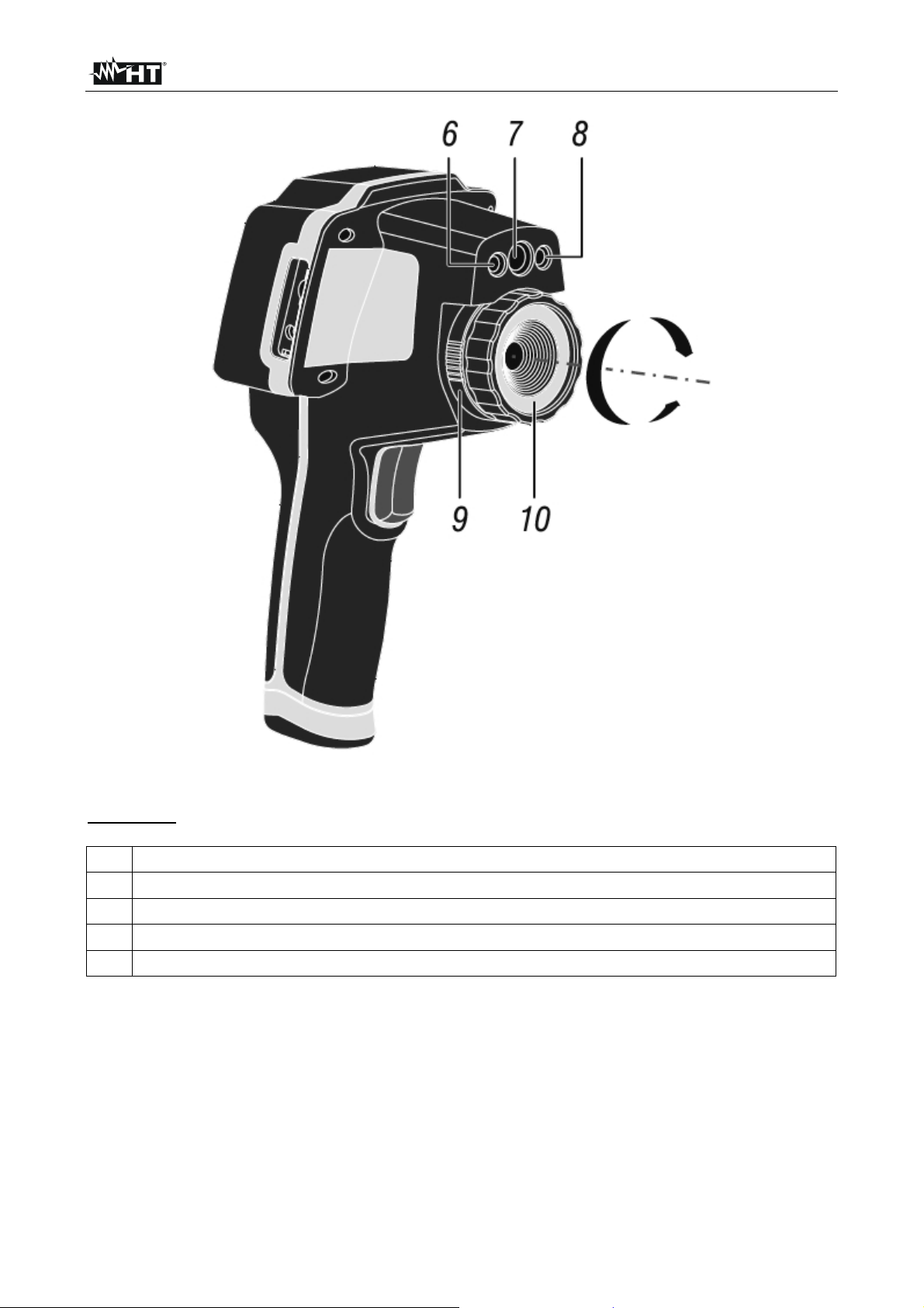
Fig. 2: Description of the instruments front side
CAPTION:
6 Built-in illuminator
7 Photo camera
8 Laser pointer
9 Lens locking/releasing mechanism
10 Lens associated with the IR sensor
EN - 7
Page 10
THT70
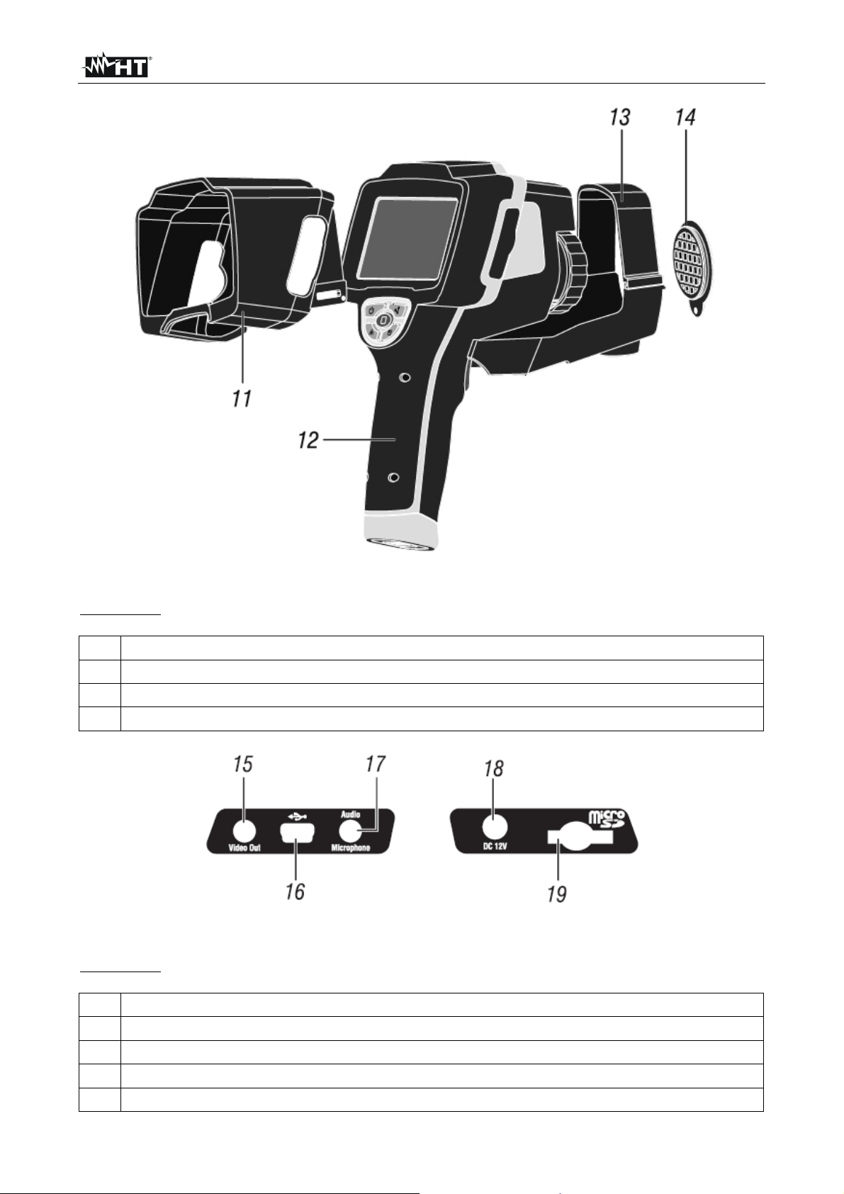
Fig. 3: General description of the instrument
CAPTION:
11 Sun shield
12 Instrument body
13 Universal adapter for tripods
14 Lens protection cap
Fig. 4: Description of the instrument's side interfaces
CAPTION:
15 Video output
16 USB port
17 Audio input for connecting microphone/headphones
18 Input for connecting AC adapter/battery charger
19 Slot for micro SD card insertion
EN - 8
Page 11
THT70
4.2 DESCRIPTION OF FUNCTION KEYS
The instrument has 5 function keys indicated as , , , , further in the
manual and a trigger key “T” with multiple functions.
4.2.1 Switching on/off the instrument
Press and hold the key for approx. 3 seconds to switch on the instrument. After approx.
20 seconds internal autotest, the instrument shows its normal measuring screen.
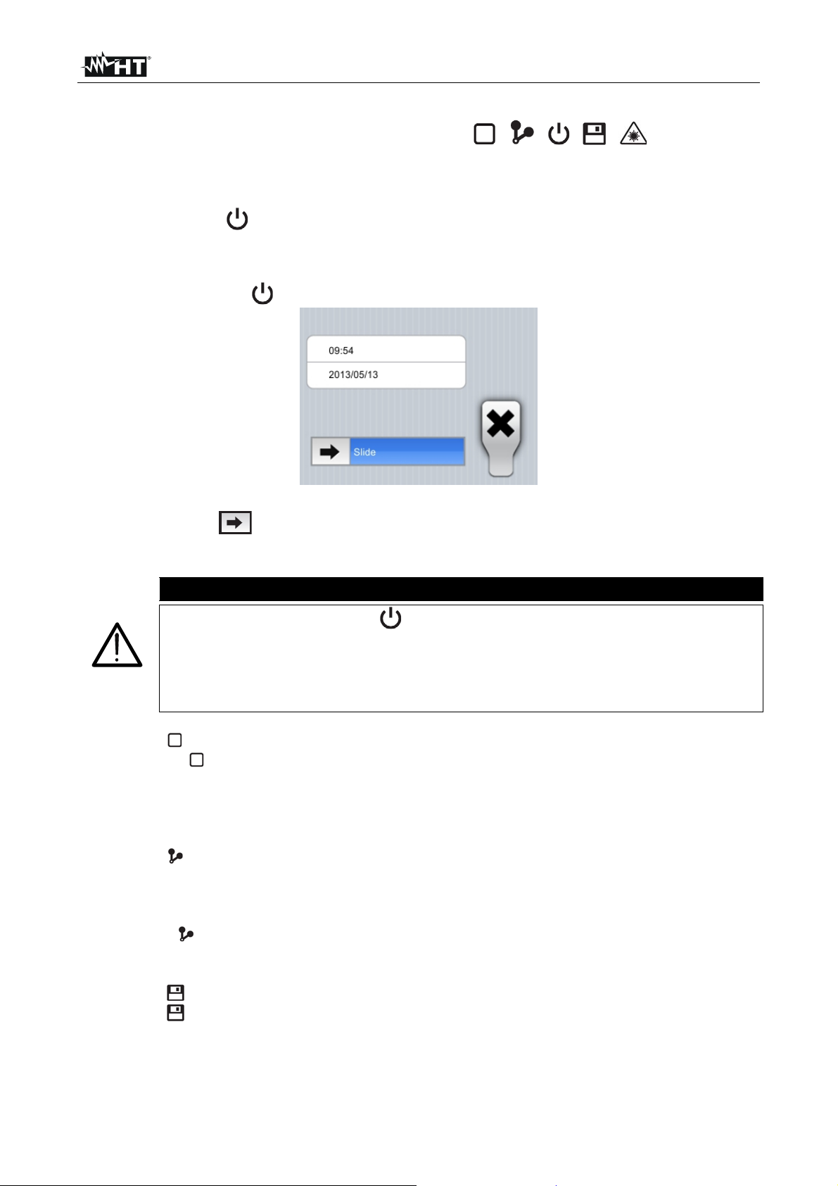
To switch off the instrument, proceed as follows:
1. Press and hold the key for 3 seconds. The instrument shows the following screen:
Fig. 5: Instrument switch-off screen
2. Drag the icon to the right until the end of the blue section. The instrument will
automatically switch off after a few seconds. Touch the “X” key to cancel the operation.
CAUTION
A simple pressing of the key only causes the display to switch off and
on again. The instrument also allows the display to automatically switch
off after a selected time (see § 5.2.1.2).
The instrument may take approx. 10s to switch off in case it is connected
to the external power supply.
4.2.2 Key
Pressing the
key allows showing/hiding the icons of the instrument's main menu
(operation possible also by touching the display), setting the value of the distance from the
object in Fusion screens (see § 5.1.3) and quitting the internal function screens and going
back to the main menu.
4.2.3 Key
The IR image on the display may be out of focus after a few minutes or if a new object is
framed. In order to solve this problem it is necessary that the instrument performs its
internal calibration. It is possible to manually calibrate the instrument at any time by
pressing the key, or to let the instrument calibrate itself automatically after a certain set
time (see § 5.2.1.2).
4.2.4 Key
Press the key to automatically save the IR image shown on the display in the
instrument's memory (micro SD card) (see § 5.2.4.1).
EN - 9
Page 12
THT70
4.2.5 Key
Press and hold the “ ” key to switch on the laser pointer which is always active on the
instrument. A small red circle “ ” is found in the middle and on the top left-hand side of
the display. Releasing the key automatically deactivates the laser pointer.
Simply press the “ ” key to activate/deactivate the built-in illuminator with white LED light.
The symbol “ ” appears in the top left-hand part of the display.
4.2.6 T key (Trigger)
Pressing the T key found in the front part of the instrument allows freezing (Hold) the IR
image on the display and automatically opens the section for saving the image (see §).
The symbol “ ” is found in the top part of the display. Press the T key again to save the
image and quit the Hold status.
EN - 10
Page 13
THT70
5 OPERATING INSTRUCTIONS
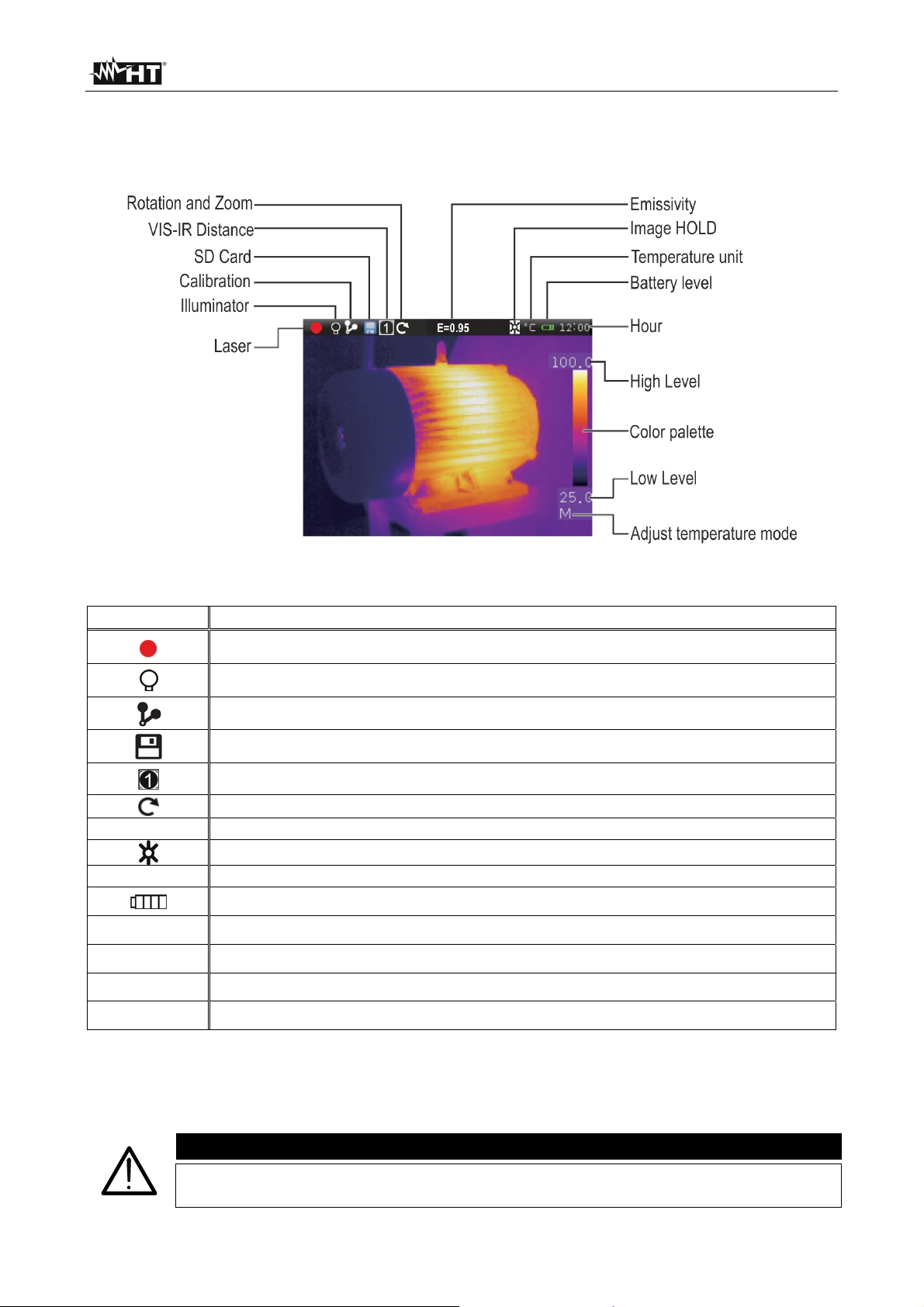
5.1 DESCRIPTION OF THE MAIN INTERFACE
The instrument shows the following main interface on the display:
Fig. 6: Main instrument interface
The meaning of the symbols found on the display is described below.
Symbol Description
E=0.95
°C
12.00
Level
Palette
Active laser pointer (see § 4.2.5)
Active built-in illuminator (see § 4.2.5)
Manual or automatic calibration activated (see § 4.2.3)
Micro SD card inside the instrument
Setting of distance from object in VIS-IR screens (see § 5.1.3)
Activation of rotation menu and image zoom (see § 5.1.2)
Set value of object emissivity
Active HOLD function (see § 4.2.6)
Temperature measuring unit selected on the instrument (see § 5.2.1.1)
Battery charge level indication (see § 7.2)
Indication of the system's current time (see § 5.2.1.1)
Indication of temperature levels of the IR image (see § 5.2.3.3)
Indication of colour palette (see § 5.2.3.2)
M,Auto,IG
Indication of image temperature adjustment mode (see § 5.2.3.3)
5.1.1 Image focusing
Focusing the IR image found on the instrument display must be performed manually by
rotating the lens installed on the IR sensor (see Fig. 1 - Pos.1). Keep the instrument
steady while performing this operation.
CAUTION
Always focus the image before saving it, in order to perform correct
temperature measurements of the framed object.
EN - 11
Page 14
THT70
5.1.2 Image rotation and zoom
The instrument allows performing complete rotations (0 360°) and has a digital electronic
zoom function “x1 x20” of the framed IR image. To use these functions, proceed as
follows:
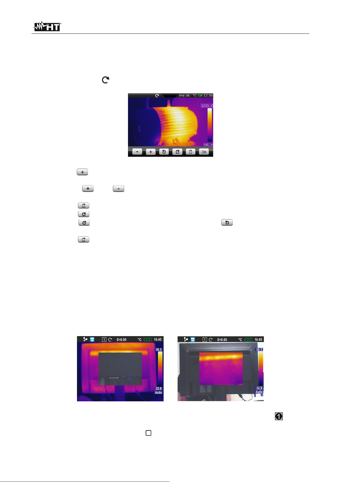
1. Touch the symbol “ ” on the display. The instrument shows the following menu at the
bottom of the display:
Fig. 7: Menu for setting image rotation and zoom
2. Press the “ ” key to activate the zoom function. The indication “0° / 1.1” is shown on
the display and the image is zoomed in 10% more with respect to the original image.
3. Touch the “ ” or “ ” keys to increase or decrease the image zoom with a
resolution of 10%. Zoom range 1.1 20.0
4. Touch the “ ” key to restore normal image view.
5. Touch the “ ” key to activate rotation. The indication “1°/1.0” appears on the display
6. Touch the “ ” key to rotate the image clockwise of the “ ” key to rotate the image
counterclockwise with a resolution of 1°. Rotation range 0° 360°
7. Touch the “ ” key to restore normal image view.
8. Touch the “OK” key to quit the menu.
5.1.3 Adjusting the distance of the object in Fusion screens
In “IR_MIX_VIS” and “VIS_MIX_IR” display mode (see § 5.2.3.1), due to the different
position of the lens and of the built-in photo camera, when the object is close to the lens,
the visible image tends to become bigger, while the IR image tends to reduce. When the
object is more than 5m far from the lens, this effect tends to disappear The instrument
allows setting the distance of the object in order to compensate the effect at distances
shorter than 5m. Proceed as follows:
1. Select the “IR_MIX_VIS” or “VIS_MIX_IR” display on the instrument (see §). The
instrument shows the following screens:
Fig. 8: Adjusting the distance of the object in Fusion screens
2. At the top of the display, the instrument automatically shows the symbol “ ”, where
the value indicated inside the square represents the last value set for distance.
3. Press and hold for 2 seconds the key to set the value of distance of the lens from the
object. The following values are available: 1/2m (0.5m), 1m, 2m and 5m
EN - 12
Page 15
THT70
5.2 MAIN MENU DESCRIPTION
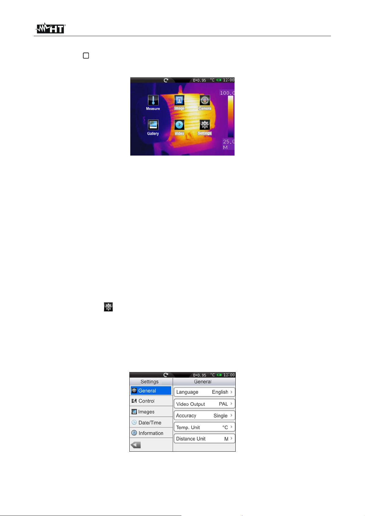
Pressing the key or simply touching the display, the instrument shows/hides the
following main menu consisting in 6 icons which allow accessing all internal functions:
Fig. 9: Main instrument menu
Measure menu defines the properties of the tools which can be used for measuring
(cursors, lines, areas, object parameters, alarm conditions).
Image menu defines the display mode of IR, Visible and Fusion images, the
Automatic/Manual modes and the Isotherm line tool.
Camera menu defines the saving modes of IR images and videos.
Gallery menu includes the gallery of the IR images saved in the micro SD card.
Video menu includes the list of the IR videos saved in the micro SD card.
Settings menu allows setting system parameters.
5.2.1 Settings Menu
By touching the icon the instrument enters the “Setting” menu, in which it is possible to
define the values of system parameters.
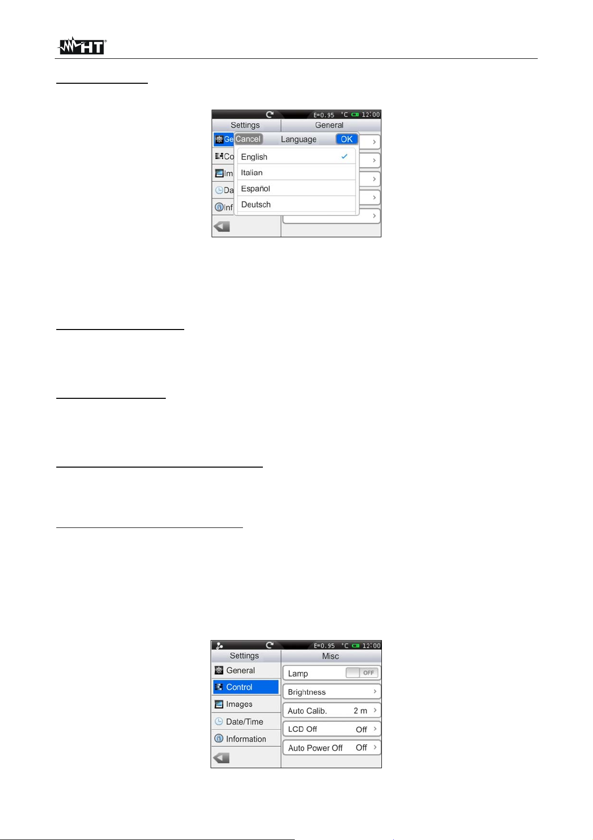
5.2.1.1 “General” section
In this section (see Fig. 10) it is possible to define the system language, the type of video
output, the accuracy in temperature measurement, the measuring unit of temperature and
distance.
Fig. 10: “General” section, Setting menu
EN - 13
Page 16
THT70
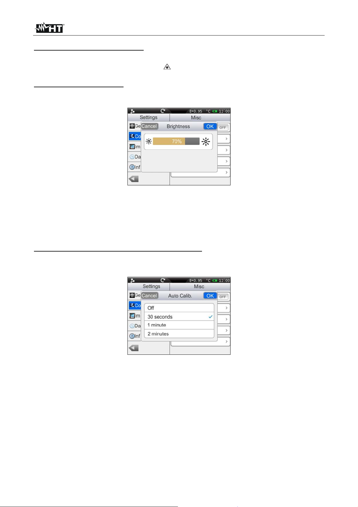
Language setting
1. Touch the box “Language”. The following screen appears on the instrument's display:
Fig. 11: System language setting
2. Scroll the list of the available languages and touch the desired one. A tick “” is
inserted into the corresponding line.
3. Touch “OK” to save your choice and exit the screen or “Cancel” to exit without saving.
Setting the Video output
Touch the box “Video output”. The following options are available to define the type of
video system to which to connect the instrument on the terminal with the same name (see
Fig. 4 – Part 15): PAL, NTSC, Off (disabled output)
Setting the Accuracy
Touch the box “Accuracy” to define the instrument's accuracy when measuring
temperature. Following options are available: Single (the value is displayed with one
decimal figure). Double (the value is displayed with two decimal figures).
Setting the temperature measuring unit
Touch the box “Temp. Unit” to define the measuring unit used by the instrument when
measuring temperature. Available options are: °C, °F (°F = 32 + 1.8x°C), °K (°K = °C +
273.15)
Setting the distance measuring unit
Touch the box “Distance Unit” to define the measuring unit used by the instrument when
measuring the distance from the object. Available options are: M (metres), FT (feet) (FT =
0.3048xM)
5.2.1.2 “Control” section
In this section (see Fig. 12) it is possible to define the activation of the built-in illuminator,
set display brightness, the automatic calibration time, the display's switch-off time and the
instrument's auto power-off time.
Fig. 12: “Control” section, Setting menu
EN - 14
Page 17
THT70
Activation of the built-in illuminator
Touch the box “Lamp” to activate (ON) or deactivate (OFF) the built-in illuminator
(operation possible also by pressing the key)
Adjusting display brightness
1. Touch the box “Brightness”. The following screen appears on the instruments display:
Fig. 13: Setting display brightness
2. Scroll the adjusting bar until reaching the desired brightness percentage visible in real
time on the display. A very high level means an increased consumption of the internal
battery.
3. Touch “OK” to save your choice and exit the screen or “Cancel” to exit without saving.
Adjusting the automatic calibration time (see § 4.2.3)
1. Touch the box “Auto Calib.”. The following screen appears on the instruments display:
Fig. 14: Setting the automatic calibration time
2. Scroll the list of the available options: 30s, 1min, 2min and Off (autocalibration
deactivated) and touch the desired one. A tick “” is inserted into the corresponding
line.
3. Touch “OK” to save your choice and exit the screen or “Cancel” to exit without saving.
EN - 15
Page 18

THT70
Adjusting the display's switch-off time
1. Touch the box “LCD Off” to activate/deactivate and adjust the display's automatic
switch-off time. The following screen appears on the instruments display:
Fig. 15: Setting the display's switch-off time
2. Scroll the list of the available values: 1min, 2min, 5min and Off (deactivated option)
and touch the desired one. A tick “” is inserted into the corresponding line. With the
display switched off it is sufficient to touch the screen or any other key to switch it on
again.
3. Touch “OK” to save your choice and exit the screen or “Cancel” to exit without saving.
Adjusting the instrument's Auto Power-Off time
1. Touch the box “Auto Power Off” to activate/deactivate and adjust the auto power-off
time of the instrument after a period of inactivity. The following screen appears on the
instrument's display:
Fig. 16: Setting the instrument's auto power-off time
2. Scroll the list of the available values: 5min, 10min, 30min and Off (deactivated option)
and touch the desired one. A tick “” is inserted into the corresponding line.
3. Touch “OK” to save your choice and exit the screen or “Cancel” to exit without saving.
EN - 16
Page 19

THT70
5.2.1.3 “Images” section
In this section it is possible to activate the automatic image saving option with
programmable temporal scan.
Fig. 17: “Images” section, Setting menu
1. In the box “Repeat”, select the option “ON” to activate the function and touch some
internal point of the section. The following screen appears on the instrument's display:
Fig. 18: Setting the image saving time
2. Touch the keys “+” or “-” to define both the numerical value of time with a resolution of
1 unit and the choice of “Hours”, “Minutes” or “Seconds”. By touching the numerical
value field, the instrument automatically opens a virtual keyboard (see Fig. 18 – Right
side) in which it is possible to quickly enter any value. Confirm with “OK” on the
keyboard the desired value.
3. Touch “OK” to save your choice and exit the screen or “Cancel” to exit without saving.
EN - 17
Page 20

THT70
5.2.1.4 “Date/Time” section
In this section it is possible to set the system date/time of the instrument in various
formats.
Fig. 19: “Date/Time” section, Setting menu
1. Touch the box “Date Format” and select the desired date format considering the
options: mm-dd-yyyy, dd-mm-yyyy and yyyy-dd-mm (see Fig. 19).
2. Touch “OK” to save your choice and exit the screen or “Cancel” to exit without saving.
3. Touch the box “24 Hours (ON) / 12 Hours (OFF)”, choosing the desired time format.
4. Touch the box “set Time” and the keys “+” and “-” to set current time.
5. Touch “OK” to save your choice and exit the screen or “Cancel” to exit without saving.
5.2.1.5 “Information” section
This section contains the information relevant to the instrument such as model, serial
number, production date, and internal Firmware version. In the lower part, the space
already used on the micro SD card is indicated, as well as the space still available for
saving data, expressed in MB, with reference to the card's dimension.
Fig. 20: “Information” section, Setting menu
In each screen, touch the key “
” to go back to the main instrument's menu.
EN - 18
Page 21

THT70
5.2.2 Measure Menu
By touching the icon the “Measure” menu is entered, in which it is possible to
activate/deactivate and define the characteristics of the measuring tools and temperature
analysis. The thermal camera has:
Max 3 dynamic measuring cursors
Max 2 dynamic horizontal and vertical lines
Max 3 dynamic measuring areas
5.2.2.1 Setting of measuring cursors
In the Measurement menu, by touching the icon “ ” it is possible to activate/deactivate
up to 3 cursors at the same time, which can be freely positioned onto the image found on
the display, to which the temperatures of the spots on the image are associated.
Fig. 21: Setting of measuring cursors
1. Touch the icon “ ” to activate the desired cursor. The icon “ ” and the activated
cursor appear on the display.
2. Touch the icon “ ” to select the modes which can be associated to each cursor (see
Fig. 22). Following options, which exclude one another, are available: Manual (cursor
freely managed by the user), Max (cursor associated to the hottest spot of the image),
Min (cursor associated to the coldest spot of the image). The selection is indicated by
the icon “
” on the display
Fig. 22: Measuring modes associated to cursors
3. In manual mode the cursor takes the shape “ ” with identifier “1”, “2” or “3” and the
label “P1”, “P2” or “P3” indicated next to the associated temperature value appears at
the top left-hand side of the display. The cursor turns red when it is selected and can
be moved on the image while it is white when it is fixed on the image (see Fig. 21).
4. In Max mode the cursor takes the shape “
” when looking for the hottest spot.
5. In Min mode the cursor takes the shape “ ” when looking for the coldest spot.
6. Touch the icon “ ” to set the parameters associated to the single cursors (see §
5.2.2.5). The following screen appears on the instrument's display:
EN - 19
Page 22

THT70
Fig. 23: Setting the parameters associated with the cursors
7. Touch the option “Use global parameters” to associate the values of the parameters
globally defined on the instrument to the cursor (see §). The symbol “ ” is found on
the display and the fields below it are deactivated.
8. With the previous option deactivated (see Fig. 23) it is possible to associate values of
parameters “Emissivity”, “Distance” and “Offset” different from the global ones to the
cursor. To this purpose, touch the field of the parameter highlighted in red and the
symbols “<” and “>” to decrease or increase the value. Keep the keys pressed for a
quick selection of the values, The measuring ranges are the following:
Emissivity 0.01 1.00
Distance 0m 5000m
Offset -10°C 10°C
9. For the parameter Emissivity it is possible to select the value according to an integrated
table of the most common materials. Touch the field of the parameter. The following
screen appears on the display:
Fig. 24: Table with emissivity values of common materials
10. Scroll the screen, touching the desired material or select the item “Custom” and
activate the symbol “
”. Touch “OK” to confirm or “Cancel” to go back to the previous
screen
11. Press the “ ” key to go back to the previous screen
EN - 20
Page 23

THT70
5.2.2.2 Setting of Measuring lines
In the Measurement menu, by touching the icon “ ” it is possible t o activate/deactivate 2
horizontal and vertical lines at the same time, which can be freely positioned onto the
image for the description of the temperature profile
Fig. 25: Setting of Measuring lines
1. Touch the icon “ ” to activate the desired line. The icon “ ” and the selected line
appear on the display (see Fig. 26). On each line, a mobile cursor “” is found, which
identifies the point of the line in which the instrument carries out a temperature
measurement. Each line and its relevant cursor can be dragged to any point of the
image displayed. On the top left-hand part of the display there are the labels “L1” and
“L2” of the lines and the value of temperature associated to the cursors. The line, the
cursor and the label of the selected line are displayed in red, while they are white when
they are fixed to the image.
Fig. 26: Display of Measuring lines
2. Touch the icon “ ” to set the precise value in pixel of the position of the cursor of the
Line displayed (see Fig. 27).
Fig. 27: Setting the position of the cursor of the Line
3. Touch the keys “<” and “>” to set the pixels of line and column. Keep the keys pressed
for a quick selection. Available ranges: Row [21 235], Column [5 315]
4. Press the “
” key to go back to the previous screen
EN - 21
Page 24

THT70
5. Touch the icon “ ” to set the parameters associated to the lines (see § 5.2.2.5). The
following screen appears on the instrument's display:
Fig. 28: Setting the parameters associated to the horizontal Line
6. Touch the option “Use global parameters” to associate the values of the parameters
globally defined on the instrument to the line (see §). The symbol “ ” is found on the
display and the fields below it are deactivated.
7. With the previous option deactivated (see Fig. 23) it is possible to associate values of
parameters “Emissivity”, “Distance” and “Offset” different from the global ones to the
line. To this purpose, touch the field of the parameter highlighted in red and the
symbols “<” and “>” to decrease or increase the value. Keep the keys pressed for a
quick selection of the values, The measuring ranges are the following:
Emissivity 0.01 1.00
Distance 0m 5000m
Offset -10°C 10°C
8. For the parameter Emissivity it is possible to select the value according to an integrated
table of the most common materials. Touch the field of the parameter. The following
screen appears on the display:
Fig. 29: Table with emissivity values of common materials
9. Scroll the screen, touching the desired material or select the item “Custom” and
activate the symbol “ ”. Touch “OK” to confirm or “Cancel” to go back to the previous
screen
10. Touch the “ ” key to go back to previous screen and then to the main menu.
EN - 22
Page 25

THT70
5.2.2.3 Setting of measuring areas
In the Measurement menu, by touching the icon “ ” it is possible to activate/deactivate at
the same time max 3 areas which can be freely positioned onto the image. The Max, Min
and Average values of the internal spots within each selected area may be associated.
Fig. 30: Setting of measuring areas
1. Touch the icon “ ” to activate the desired area. The icon “ ” and the activated area
appear on the display (see Fig. 31). Each area can be dragged to any point of the
image displayed. In the top left-hand part of the display there are the labels “A1H”,
“A1L” and “A1A”, which respectively indicate the Maximum, Minimum and Average
temperature value of the internal spot within the area. The positions of the Max and Min
spots are indicated with the icons “ ” and “ ” on the image. The area, the label (“1”,
“2” and “3”) and the Min, Max, Average values of the selected area are displayed in
red, while they appear in white when they are fixed to the image.
Fig. 31: Display of Measuring area
2. Touch the icon “ ” to select the following display options on the Measuring areas (see
Fig. 32): Max (Maximum value of the internal spots within the area), Min (Minimum
value of the internal spots within the area), Average (Average value of the internal
spots within the area). The selection is indicated by the icon “
” on the display.
Fig. 32: Setting the parameters associated with the measuring area
3. Press the “
” key to go back to the previous screen
EN - 23
Page 26

THT70
4. Touch the icon “ ” to set the parameters associated to the areas (see § 5.2.2.5). The
following screen appears on the instrument's display:
Fig. 33: Setting the parameters associated with the areas
5. Touch the option “Use global parameters” to associate the values of the parameters
globally defined on the instrument to the area (see §). The symbol “ ” is found on the
display and the fields below it are deactivated.
6. With the previous option deactivated (see Fig. 23) it is possible to associate values of
parameters “Emissivity”, “Distance” and “Offset” different from the global ones to the
area. To this purpose, touch the field of the parameter highlighted in red and the
symbols “<” and “>” to decrease or increase the value. Keep the keys pressed for a
quick selection of the values, The measuring ranges are the following:
Emissivity 0.01 1.00
Distance 0m 5000m
Offset -10°C 10°C
7. For the parameter Emissivity it is possible to select the value according to an integrated
table of the most common materials. Touch the field of the parameter. The following
screen appears on the display:
Fig. 34: Table with emissivity values of common materials
8. Scroll the screen, touching the desired material or select the item “Custom” and
activate the symbol “ ”. Touch “OK” to confirm or “Cancel” to go back to the previous
screen
9. Touch the “ ” key to go back to previous screen and then to the main menu.
EN - 24
Page 27

THT70
5.2.2.4 Setting the Measure Menu
In the Measure menu, touch the icon “ ” to define:
The global settings of the correction parameters of temperature measurement
The general settings of the measuring parameters
Configuring the alarm conditions on temperature measurement
Fig. 35: Setting the Measurement Menu
Setting the global parameters
1. Touch the item “Global parameters”. The following screen appears on the instrument's
display:
Fig. 36: Setting the global parameters
2. Set the values of global parameters “Emissivity”, “Distance” and “Offset” (see § 5.2.2.5)
relevant to the measuring object by touching the relevant fields (see Fig. 36).
3. For the parameter Emissivity it is possible to select the value according to an integrated
table of the most common materials. Touch the field of the parameter. The following
screen appears on the display:
Fig. 37: Table with emissivity values of common materials
4. Touch the field “Reset parameters” to restore the default conditions on the instrument .
The following screen appears on the display:
EN - 25
Page 28

THT70
Fig. 38: Restoring default conditions on the instrument
5. Touch the “Yes” key to restore the default conditions (see Table 1) or the “No” key to
cancel the operation.
Parameter Default setting
Emissivity 0.95
Distance 5m
Environmental temperature 25°C
Relative humidity 60%RH
Reflected temperature 25°C
Offset 0.0°C
Table 1: Thermal camera default settings
Setting the general measuring parameters
1. Touch the item “ Measure Setting”. The following screen appears on the instrument's
display:
Fig. 39: Setting the general measuring parameters
2. The parameters whose field is included within the symbols “ <” and “>” can be set by
the user.
Lens Indication of the type of IR lens installed on the instrument. This parameter
is automatically modified by the instrument by changing the lens. Possible options:
22mm (default), 11mm, 38mm
Range Indication of the temperature measuring range. Options: -20°C 150°C
and 0 400°C
T. Env: Environmental temperature setting Measuring range: -40°C 125°C
Humidity Relative humidity setting. Measuring range: 1%RH 100%RH
T. Ref Reflected temperature setting. Range: -100°C 2000°C
3. Press the “
” key to go back to the previous screen
EN - 26
Page 29

THT70
Setting the alarm on measurement
1. Touch the icon “ ” of item “Alarm”. The following screen appears on the instrument's
display:
Fig. 40: Setting the alarm conditions on measurement
2. The parameters whose field is included within the symbols “ <” and “>” can be set by
the user.
Target It allows selecting one of the 3 measuring cursors (see § 5.2.2.1) found
on the instrument to which to associate the alarm condition on temperature
measurement. Possible options: Curs. 1, Curs. 2 or Curs. 3
Mode It allows defining the type of alarm threshold according to temperature
measurement. Possible options: Lower, Higher, Same
Temp. It allows setting the value of the temperature threshold associated to the
selected mode. Measuring range: -20°C 400°C
EN - 27
Page 30

THT70
5.2.2.5 Control parameters of temperature measurement
The thermal camera allows correcting the measured value of temperature by means of the
tools (Spots, Lines and Areas) in the following ways:
Global mode the values of the control parameters associated to all tools are defined
globally.
Custom mode each tool may independently take different values of control
parameters according to the selections made by the user.
Parameter Emissivity
In order to carry out accurate temperature measurements, it is important to define the
correct emissivity value (), which represents the ability of a body to emit infrared radiation,
according to the kind of material the measured object is made of Table 2 shows the
emissivity values for the most common materials. Emissivity takes values between 0
(mirror or perfectly reflecting surface) and 1 (perfectly radiating blackbody). Most of the
painted or oxydized surfaces have an emissivity value of approximately 0.95.
Material
Material
Black body 1 00 Steel (oxidized) 0.79
Smooth carbon surface 0.98 Very oxydized copper 0.78
Ice crystals 0.98 Cotton cloth 0.77
Human skin 0.98 Sand 0.76
Slate 0.97 Non-enameled silicone 0.75
Distilled water 0.96 Oxydized iron at 100°C 0.74
Smooth ice 0.96 C20A coating 0.73
Wet ground 0.95 Basalt 0.72
Carbon soot 0.95 Graphitized carbon at 500°C 0.71
Clean glass plate 0.94 Red rust 0.70
Paint, oil 0.94 Very rusty iron 0.69
Red brick 0.75 Water 0.67
White paper 0.93 Black soil 0.66
Cement 0.97 White cement 0.65
Dry ground 0.92 Oxydized wrought iron 0.64
Rough plaster coating 0.91 Oxydized lead at 1100°Z 0.63
Oak wood 0.90 Zirconium on inconel 0.62
Enameled earthenware 0.90 Oxydized copper-zinc 0.61
Firn 0.89 Inconel sheets at 760°C 0.58
Enameled silicone 0.88 Dressed white marble 0.56
Copper oxyde at 38°C 0.87 Anodized chrome 0.55
Ground corundum 0.86 Clean wrought iron 0.21
Snow 0.85 Ground brass 0.20
Oxydized stainless steel at
800°C
0.85 18-8 stainless steel 0.16
Oxydized iron at 500°C 0.84 Coarse aluminium 0.09
Oxydized copper at 260°C 0.83 Clean steel 0.07
Fine snow 0.82 Clean aluminium 0.05
Non-oxydized brass 0.81 Clean copper 0.05
D convex glass 0.80 Bright brass 0.03
Table 2: Emissivity values of typical materials
Associated to each control tool (Spots, Lines, Areas) there is an internal table from which
to select the emissivity value of common materials and define a custom value (see §
5.2.2.1, § 5.2.2.2 and § 5.2.2.3).
EN - 28
Page 31

THT70
Parameters reflected temperature and environmental temperature
Objects with a low emissivity may reflect infrared energy coming from adjacent objects;
this energy is added to the energy of the object itself, thus causing possible measurement
mistakes. In several situations, there are sources of heat with a higher temperature than
the temperature found near the object being measured. In this case, it is necessary to
compensate this reflected energy by entering the presumed temperature value of the
adjacent heat source into the thermal camera. In most of the applications, the reflected
temperature is identical to the environmental temperature and has negligible effects on
temperature measurement on objects with a high emissivity.
Environmental temperature which can be set within the range: –40°C 125.0°C
Reflected temperature which can be set within the range: –100°C 2000.0°C
Parameter Offset
This parameter can be set if, in automatic mode, you are sure of the values which the
temperature levels associated with the colour palette must take (see § 5.2.3.3). In this
case, the levels ate increased or decreased by the quantity inserted in that field.
Offset which can be set within the range: -10°C 10.0°C
Parameter Distance
This parameter identifies the distance between the thermal camera and the object to be
measured. In most of the applications, the temperature levels associated to the colour
palette (see § 5.2.3.3) are influenced negligibly by small variations of distance. Therefore,
it is possible to leave this parameter set to the default value without having significant
errors on measurement. For distances higher than 300m it is possible to have variations >
1°C in temperature level.
Distance which can be set within the range: 0m 5000m
Parameter Relative humidity
This parameter identifies the value of relative humidity of the environment where
measurement is carried out. In most of the applications, the temperature levels associated
to the colour palette (see § 5.2.3.3) are influenced negligibly by small variations of
humidity. Therefore, it is possible to leave this parameter set to the default value without
having significant errors on measurement.
Relative humidity %RH which can be set within the range: 1% 100%
EN - 29
Page 32

THT70
5.2.3 Image menu
By touching the icon the “Image” menu is entered, in which it is possible:
To set the display type of the IR and visible image on the display
Define the colour palettes associated with the IR image
Set the temperature level of the image and the image mode
Define the characteristics of the Isotherm line tool
5.2.3.1 Setting the display type
In the Image menu, by touching the icon “ ” it is possible to define the type of desired
display by choosing between the following options:
IR display of IR image only (see Fig. 41)
Visible display of visible image only (see Fig. 42)
IR_FUSION_VIS Display of visible image within the IR image, with the possib ility of
choosing the position to the sides of the display (see Fig. 43).
VIS_FUSION_IR Display of IR image within the Visible image, with the possibility of
choosing the position to the sides of the display (see Fig. 44).
IR_MIX_VIS Display of visible image in the middle of the screen/full screen of the IR
image with the possibility of choosing the percentage value of the visible level (see Fig.
45).
VIS_MIX_IR Display of IR image in the middle of the screen/full screen of the visible
image with the possibility of choosing the percentage value of the IR level (see Fig. 46).
Fig. 41: Setting and displaying the IR image
Fig. 42: Setting and displaying the visible image
EN - 30
Page 33

THT70
Fig. 43: Setting and displaying the IR_FUSION_VI image
Fig. 44: Setting and displaying the VIS_FUSION_IR image
Fig. 45: Setting and displaying the IR_MIX_VIS image
Fig. 46: Setting and displaying the VIS_MIX_IR image
1. Touch the symbols “<” and “>” to select the type of desired display.
2. In modes “IR_FUSION_VIS” and “VIS_FUSION_IR”, touch the symbols “<” and “>” t o
select the position between the options: “BR” (at the bottom on the right), “BL” (at the
bottom, on the left), “TR” (at the top, on the right) and “TL” (at the top, on the left).
3. In modes “IR_MIX_VIS” and “VIS_MIX_IR” touch the symbols “<” and “>” to select the
dimensions of the internal frame in item “Measurement” between the options “Half” and
“Whole” and the percentage value of the IR or Visible level in item “Percent” with
range: 0% 100%
EN - 31
Page 34

THT70
5.2.3.2 Setting the colour palette
In the Image menu, by touching the icon “ ” it is possible to select the type of colour
palette which can be associated to the IR image by choosing between the following
options:
Standard palette allows choosing between 8 different standard palettes
User palette allows the user to define up to 10 custom palettes (2 fixed + 8 which
can be fully customized) (this function can be used in Manual mode only – see §
5.2.3.3)
Standard palette
1. Touch the item “Standard palette”. The following screen appears on the instrument's
display:
Fig. 47: Setting the standard palette
2. Scroll the entire length of the Table with your finger in order to find the desired option
and activate the symbol “ ”. Touch “OK” to confirm or “Cancel” to go back to the
previous screen. Notice the presence of the colours of the palette in the lower part of
the display. The following standard palettes are available:
Iron, Rainbow, Grey, Grey Inverted, Sepia, Blue_Red, Hot_Cold, Feather
User palette
1. In manual mode, touch the item “Custom palette”. The following screen appears on
the instrument's display:
Fig. 48: Setting the user palette
EN - 32
Page 35

THT70
2. The instrument makes two palettes named “Custom1” and “Custom2” which can be
freely customized, but cannot be eliminated. These palettes have a default grey colour.
3. Touch one of the two palettes to select them by activating the symbol “ ”.
4. Touch for approximately 2 seconds the line corresponding to the selected palette.
The following screen appears on the display:
Fig. 49: Customizing the user palette name
5. Touch the item “Rename” to change the name of the palette (max 8 figures). An
internal virtual keyboard is shown on the display (see Fig. 49). Confirm the operation
with “OK”.
6. Touch the item “Add” to add further custom palettes (see Fig. 50). It is possible to add
max 8 palettes further to the two available by default. By touching the item “Remove”
it is possible to remove custom palettes, except for the two already available by default.
7. Touch the icon “
appears on the display:
Fig. 51: Customizing the user palette colours – Step 1
Fig. 50: Insertion of new user palettes
” for a complete definition of customization. The following screen
EN - 33
Page 36

THT70
8. The screen shows the default palette in uniform grey with division markers in 4 parts in
a default temperature range of 0.0°C/F (MIN) 50.0°C/F (MAX) with values of: 12.5,
25.0 and 37.5
9. Touch the MIN 0.0 value and/or the MAX 50.0 value. The following screens are
shown on the display:
Fig. 52: Customizing the user palette colours – Step 2
10. Touch the symbols “ <” and “>” to set:
Min value: The minimum value of the manual temperature range in the
instrument's measuring range: -20°C 400°C
Max value: The maximum value of the manual temperature range in the
instrument's measuring range: -20°C 400°C
The values of the colours associated to the RGB model (Red, Green, Blue) in a
range between 0 255. Setting is possible both by ins erting numerical values, and
by touching the cursors “” and “” on the colour spectrum and observing the
resulting effect on the bar positioned at the top of the display (see Fig. 52 – right
side).
11. Confirm the operation with “OK” or press “Cancel” to exit without saving and go back to
the previous screen.
12. Drag the 4 division markers of the temperature range along the bar until the desired
intermediate temperature values are obtained (see Fig. 53 – right side).
Fig. 53: Customizing the user palette colours – Step 3
13. Touch the division markers and set:
The values of the colours associated to the RGB model (Red, Green, Blue) in a
range between 0 255. Setting is possible both by ins erting numerical values, and
by touching the cursors “” and “” on the colour spectrum and observing the
resulting effect on the bar positioned at the top of the display (see Fig. 53 – left
side).
Activation of the marker with sign “” in the “Activate” range. The symbol “
” is
found on the bar of the palette (see Fig. 53 – right side).
14. Confirm the operation with “OK” or press “Cancel” to exit without saving and go back to
the previous screen.
EN - 34
Page 37

THT70
5.2.3.3 Adjusting the image temperature
In the Image menu, touch the icon “ ” to set the adjusting mode of the temperature
associated with the image framed on the display. The following options are available:
Automatic (Auto) mode the minimum and maximum temperature levels of the
framed object on the display and associated with the colour palette are automatically
defined by the instrument and dynamically vary when moving it. This (default) option,
which can be used in most cases, allows for an optimum display of the IR image in a
condition of temperatures equally distributed within it.
Histogram (HG) mode the minimum and maximum temperature levels of the object
framed on the display are always defined automatically by the instrument, as in Auto
mode, but in this case, the areas of the image in which temperature values are very
different from the values of adjacent areas are highlighted.
Manual (M) mode the minimum and maximum temperature levels of the object
framed on the display are manually set by the user, who can associate, if necessary, a
custom colour palette. This mode, particularly useful to clearly identify only some areas
of the image, is recommended in case of advanced thermographic operations.
1. Touch the symbols “<” and “>” to set the Automatic or Histogram modes. The following
screens are shown on the display: The messages “Auto” and “HG” are found in the
lower part of the colour palette.
Fig. 54: Setting the Automatic and Histogram modes
2. Touch the symbols “<” and “>” to set the Manual mode. The following screen appears
on the display:
Fig. 55: Setting the Manual mode
3. Touch the item “Adjust”. The instrument shows the following screen:
EN - 35
Page 38

THT70
Fig. 56: Selection temperature mode
CAUTION
The screen of Fig. 56 is also shown, as a shortcut, touch the high and low
level values located in the palette extremes in the right part of the display
4. Touch the icon “ ” for the setting of the adjustment mode. Touch the symbols “<” and
“>” for the selection of Automatic (A), Manual (M) or Histogram (H) modes
5. Touch the icon “ ” or the icon “ ” for the single settings of adjustment respectively of
high and low level of temperature. Touch the symbols “<” and “>” to carry out the
adjustment of the temperature range associated with the colour palette until reaching
the desired effect (see Fig. 57). Adjusting the levels is carried out with a fixed interval
defined by the instrument and which cannot be modified, and the colour palette
becomes white
Fig. 57: Single adjusting of high and low level of temperature
6. Touch the icon “ ” for the simultaneous adjustment of both high and low level of
temperature. Touch the symbols “<” and “>” to carry out the adjustment of the
temperature value associated with the palette up to reach the effect (see Fig. 58)
Fig. 58: Simultaneous adjusting of high and low level of temperature
7. At the end of the adjustment, the colour palette takes the original aspect again, with the
values of the desired minimum and maximum levels Touch the display to exit the
function
EN - 36
Page 39

THT70
5.2.3.4 Setting the Isotherm function
In the Image menu, touch the icon “ ” to select the Isotherm function and to activate a
screen clearing function. The following options are available (see Fig. 59)
Isotherm allows activating the Isotherm function and to define its characteristic.
Clear screen allows having the display cleared of all symbols.
Fig. 59: Setting the Isotherm tool
1. Touch the item “Isotherm” or the symbol “ ” to activate the Isotherm function. The
icon “ ” is shown on the display
2. Touch the icon “ ” to define the characteristics of the Isotherm line. The screen Fig.
59 is shown on the display. The meaning of the items is the following:
Mode defines the type of Isotherm. Available options are:
Between the instrument shows the spots of the image with temperature
between: [Value Value + Range] with colour defined by the user.
Higher the instrument shows the spots of the image with temperature higher
than Value + Range with colour defined by the user.
Lower the instrument shows the spots of the image with temperature lower
than Value with colour defined by the user.
Value defines the value of initial temperature the Isotherm line refers to.
Measuring range: -19.5°C 399.5°C
Width defines the value of the offset temperature interval with respect to the
initial temperature value. Measuring range: -1.0°C 420.0°C
Colour defines the colour of the Isotherm line. Possible options: Black, Green,
White, Transp. (Transparent)
3. Press the “ ” key to go back to the previous screen
4. Touch the item “Clean screen” to activate the complete clearing of the display from all
other symbols (option recommended with use of the Isotherm line tool).
5. Touch the display to exit the Isotherm line function.
EN - 37
Page 40

THT70
5.2.4 Camera menu
In this section it is possible to carry out the following operations:
Fixing the images on the display
Saving the images on the micro SD card
Carrying out voice annotations when saving the image
Carrying out text annotations when saving the image
5.2.4.1 Fixing the image on the display and saving
An IR image on the display may be saved on the micro SD card inserted in the instrument,
after it has been frozen on the display. Proceed as follows:
1. Insert the micro SD card into the relevant slot of the instrument. The icon “ ” is shown
in the top left-hand part of the display.
2. Press the T (Trigger) key to freeze an IR image on the display. The symbol “ ” appears
in the upper part of the display, the icon “
and the icon “
” becomes fully light blue “ ” (see Fig. 60 – right side). The same
” appears in the lower part of the display
result is obtained by touching the icon “ ” in the general menu and by touching the
icon “ ” (see Fig. 60 – left side). Touch the icon “ ” and then the T key to exit the
Hold function.
Fig. 60: Freezing the image on the display and saving
3. Touch the icon “ ” or press the T key again to save the image on the display. The
image is saved with the name ”YYMMDD_xxxxT” in which: “YY = Year”, “MM = Month”,
“DD = Day” and “xxxx = progressive number of saving. This indication appears for a
moment on the display.
EN - 38
Page 41

THT70
5.2.4.2 Voice annotation
While saving the image, the instrument allows inserting a vocal comment recorded by the
operator (max 60s for each image) as follows:
1. Save the image according to the procedure described in § 5.2.4.1. At the end of the
operation, the instrument's situation is shown in Fig. 61 – Left side.
Fig. 61: Inserting a voice annotation
2. Touch the icon “ ”. The screen Fig. 61 – Right side is shown on the display
3. Insert the jack of the headphones provided into the instrument (see Fig. 4 – Part 17).
4. Touch the icon “ ” to start recording the voice annotation.
5. Speak into the microphone found on the h eadphones connected to the instrument for
the desired time.
6. Touch the icon “ ” to stop recording. The following screen appears (see Fig. 62 – Left
side):
Fig. 62: Stopping a voice annotation
7. Touch the icon “ ” to save the voice annotation associat ed with the image previously
saved or the key “ ” to exit without saving. The instrument shows the screen Fig. 62 –
Right side and is ready to save the image again.
8. To listen to the voice annotation again, see § 5.2.5
EN - 39
Page 42

THT70
5.2.4.3 Text annotation
While saving the image, the instrument allows inserting a text comment entered by the
operator (possibly associated with the voice annotation) as follows:
1. Save the image according to the procedure described in § 5.2.4.1. At the end of the
operation, the instrument's situation is shown in Fig. 63 – Left side.
Fig. 63: Inserting a text annotation
2. Touch the icon “ ”. The screen Fig. 63 – Right side is shown on the display
3. Insert the desired text comment by using the virtual keyboard
4. Touch the “OK” key on the keyboard to confirm the text comment associated with the
previously saved image or the “Cancel” key to exit without saving the comment.
5. To see the text annotation again, see § 5.2.5
5.2.4.4 Recording IR videos
The instrument allows recording and saving IR videos on the micro SD card as follows:
1. Touch the icon “ ” in the general menu and move the icon “ ” to the right. The
following screen appears (see Fig. 64 – Left side):
Fig. 64: IR video recording
2. Touch the icon “ ” to start recording the IR video. The icon becomes “ ” and the
indication of the duration of the video indicated in “HH:MM:SS” appears in the upper
part of the display (see Fig. 64 – Right side).
3. Touch the icon “ ” again to stop the video and save it automatically on the micro SD
card.
4. Touch the icon “ ” to exit the function and go back to the main menu
EN - 40
Page 43

THT70
5.2.5 Gallery menu
In this section it is possible to recall on the display and see the gallery of the IR images
saved on the micro SD card inserted in the instrument. In the same section it is possible to
see the text annotations and listen to the voice annotations made while saving the images.
1. Touch the icon “ ” in the main menu. The following screen appears (see Fig. 65 –
Left side):
Fig. 65: Recalling on the display the images saved
2. The saved images are shown in reduced dimensions within the gallery in sequence
according to the date in which they were saved. Scroll laterally with your finger on the
display to change the screen in case the gallery contains many saved images.
3. The icons “ ” and “ ” possibly present on the images respectively indicate the
presence of voice and text annotations saved with the image.
4. Touch an image in the gallery to see it again. The screen Fig. 65 – Right side is shown
on the display The meaning of the symbols is the following:
“ ” and “ ” allows switching from an image to the other.
“ ” allows zooming in the image. Press and hold the icon to continuously
increase the zoom. Touch the icon “ ” to exit the screen and restore normal
display.
“ ” allows zooming out the image. Press and hold the icon to continuously
decrease the zoom. Touch the icon “ ” to exit the screen and restore normal
display.
“ ” allows rotating the image in clockwise direction. Drag the image on the
display to move it, if desired. Touch the icon “
normal display.
“
“ ” allows deleting the selected image. A message is provided by the
5. Touch the icon “ ”. The following screen appears on the display (see Fig. 66 – Left
side).
” allows exiting the section and going back to the previous screen.
instrument to confirm the operation.
” to exit the screen and restore
EN - 41
Page 44

THT70
Fig. 66: Display of voice and text annotation
6. Insert the jack of the headphones provided into the instrument (see Fig. 4 – Part 17)
and wear the headphones.
7. Touch the icon “ ” to play the voice annotation associated with the image.
8. Touch the icon “ ” to adjust the recording volume.
9. Touch the icon “ ” per stop playing at any time.
10. Touch the icon “ ” to display the text annotation. The screen Fig. 66 – Right side is
shown on the display
11. Press the “ ” key to go back to the image gallery.
12. Touch the icon “Exit” to exit and go back to the main menu.
5.2.5.1 Deleting images
The instrument allows deleting images as follows:
Touch the icon “ ” with the image recalled on the display (see § 5.2.5).
Inside the gallery, after making a selection as follows:
1. Touch the icon “ Delete” inside the image gallery. The following screen (see Fig. 67 –
Right side) is shown on the display:
Fig. 67: Selecting and deleting images
2. Touch the single images or the icon “Select all” to select all images in the gallery. The
icon “ ” is shown on the selected images.
3. Touch the single images again or the icon “Deselect all” to deselect all images in the
gallery. The icon “ ” disappears from the display
4. Touch the icon “Delete” to definitively delete the selected images (no message is
provided by the instrument to confirm the operation).
5. Press the icon “Back” to go back to the previous screen.
6. Touch the icon “Exit” to exit and go back to the main menu.
EN - 42
Page 45

THT70
5.2.6 Video menu
In this section it is possible to recall on the display and see the gallery of the IR videos
(MPEG4 format) saved on the micro SD card inserted in the instrument.
1. Touch the icon “ ” in the main menu. The following screen appears (see Fig. 68 –
Left side):
Fig. 68: Recalling saved IR videos on the display
2. The saved IR videos are shown in reduced dimensions within the gallery. Scroll
laterally with your finger on the display to change the screen in case the gallery
contains many saved videos. The first video on the left is the last saved.
3. Insert the jack of the headphones provided into the instrument (see Fig. 4 – Part 17)
and wear the headphones.
4. Touch a video icon in the gallery to see it again. The selected video is marked by the
symbol “”. The screen Fig. 68 – Right side is shown on the display The meaning of
the symbols is the following:
“ ” Play IR video
“ ” Stop IR video
“ ” Pause IR video
“ ” Back to IR video gallery
“ ” Adjust recording volume
“ ” Back to main menu
5.2.6.1 Deleting IR videos
The instrument allows deleting IR videos as follows:
1. Touch the icon “Delete” inside the IR video gallery. The following screen (see Fig. 69 –
Right side) is shown on the display:
Fig. 69: Selection and deletion of IR videos
2. Touch the single videos or the icon “Select all” to select all videos in the gallery. The
icon “ ” is shown on the selected videos.
3. Touch the single videos or the icon “Deselect all” to deselect all videos in the gallery.
The icon “ ” disappears from the display
4. Touch the icon “Delete” to definitively delete the selected videos (no message is
provided by the instrument to confirm the operation).
5. Press the icon “Back” to go back to the previous screen.
6. Touch the icon “Exit” to exit and go back to the main menu.
EN - 43
Page 46

THT70
p
5.3 USING THE INSTRUMENT
For a typical use of the instrument, please refer to the following procedure:
1. Switch on the instrument by pressing and holding the “ ” key for 3 seconds. After
approx. 20 seconds of internal autotest, the instrument shows its normal measuring
screen. The instrument shows an initial screen like the one shown in Fig. 70.
Fig. 70: Initial screen
2. It takes approx. 30 seconds for the instrument to become fully operating. During this
time interval, the instrument carries out an automatic calibration and the internal
commutations may produce some noise
CAUTION
The autocalibration sequence starts when the instrument is switched on and
continues during the thermal cameras normal operation, during which the
image freezes for a few seconds in order to eliminate offset errors. The
noise produced by the commutation of internal parts is not to be considered
as a problem of the instrument.
3. Before any measuring operation, correctly focus the thermal camera in order to prevent
having grossly inaccurate measurements and a low quality of the saved image (see §
5.1.1).
4. For accurate temperature measurements, make sure the surface of the measured
object is always bigger than the surface measurable by the instrument, which is given
by the instruments field of view (FOV). The instrument has a field of view of 25° x 19°
and a detection vector of 384x288 (110592) pixels (see Fig. 71).
384 pxl
19°
25°
25°
xl
288
Fig. 71: Representation of the instruments field of view (FOV)
EN - 44
Page 47

THT70
The representation of the ratio D (distance from the object) / S (surface of the object) for
an instrument provided with 22mm lens is described below.
Fig. 72: Representation of the instruments D/S ratio
In the representation, it is possible to see how the IFOV (Instant Field Of View =
geometrical resolution of the instrument = size of the single pxl of the IR sensor) is equal
to 1.14mm at a distance of 1m of the instrument from the object being measured. This
means that the instrument is capable of carrying out correct temperature measurements at
a distance of 1m on objects with a size not lower than 1.14 mm.
5. The typical application of thermal cameras is the one in which it is necessary to detect
a temperature difference between two adjacent objects, as this kind of analysis is often
sufficient to identify anomalies in electrical and mechanical appliances, etc. In such
situations, in which an accurate temperature measurement is not strictly necessary,
emissivity value may be set to “1” (see § 5.2.2.5), it is not necessary to consider the
objects surface, its distance and the field of view). However, if accurate measures are
required (e.g. the temperature of an electric motor), it is necessary to correctly set the
parameters previously described in this manual.
6. Correctly set the temperature range of the image (see § 5.2.1), defining the adequate
values according to the MIN and MAX temperatures detected within the measured
area.
7. Frame the objects to be measured by using the laser pointer, if necessary (see §
4.2.5). The instrument displays the temperature values associated with the measuring
cursors.
8. Use the T key (see § 5.2.4.1) to freeze the image on the display and save it in the
internal memory of the instrument or on the external micro SD card. The instrument
saves the images in sequence with file name “YYMMDD_xxxxT”. Enter possible voice
(see § 5.2.4.2) or text (see § 5.2.4.3) annotations onto the saved image.
9. Touch the icon “
” to see the saved images again (see § 5.2.5).
EN - 45
Page 48

THT70
5.4 TRANSFERRING IR IMAGES/VIDEOS ONTO THE PC
The instrument allows saving the IR images/videos on an external micro SD card and to
transfer them onto the PC by using the USB cable. Both the micro SD card and the cable
are provided with the instrument. Proceed as follows:
1. Insert the micro SD card into the instrument on one side (see Fig. 4 – Part 19).
2. Connect the USB cable to the instrument (see Fig. 4 – Part 16) and to the PC or use
the adapter for micro SD/SD card provided in case you have an SD card reader
installed on the PC.
4. Inside “My Computer”, search for the removable disk associated to the micro SD card
and copy the files “YYMMDD_xxxxT.JPG” of the desired IR images or the files
“YYMMDD_xxxxV.MP4” of the desired IR videos contained in two separate folders on
the micro SD card to a PC folder.
5.5 VIDEO OUTPUT
The video output available in the instrument (see Fig. 4 – Part 15) enables displaying the
IR image acquired on an external monitor or video recording device capable of managing
PAL or NTSC systems. To connect the instrument, proceed as follows:
1. Switch on the instrument
2. Touch the icon “ ” and setting the PAL or NTSC system (see § 5.2.1.1)
3. Connect the instrument to the external monitor or recording device using the video
cable provided.
4. Turn on the external monitor or device
5. Verify to see the IR image both on the display instrument and on the external monitor
or device with simultaneous manage of the operation
6. Touch the icon “ ” and set the type of system PAL or NTSC (see § 5.2.1.1).
7. Perform the saving/monitoring of the image on the external monitor or device
8. At the end of the operations select the option “Off” on the instrument (see § 5.2.1.1),
switch off the monitor or the external device and disconnect the video cable from the
instrument.
EN - 46
Page 49

THT70
6 USING THE THTLINK SOFTWARE
The software “THTLink” can be used to analyse the images saved on the micro SD card
inserted in the instrument.
6.1 MINIMUM SYSTEM REQUIREMENTS
Hardware: Pentium IV
RAM memory: 512MB
Output interface: USB ports or SD card reader
CD-ROM reader: present
Screen resolution: 800x600
Operating system: Windows XP o higher
Software applications: Microsoft .Net Framework 2.0 or higher
6.2 INSTALLING THE THTLINK SOFTWARE
1. Insert the installation CD-ROM into the reader of the PC.
2. Launch the file “THTLink.exe” found inside the CD-ROM and follow the guided
installation procedure
6.3 MAIN CHARACTERISTICS OF THE THTLINK SOFTWARE
With launched program, the PC shows the following initial screen:
Main characteristics of the THTLink software:
Fig. 73: Starting screen of the THTLink software
Display of IR and visual images
Insertion of advanced analysis tools (points, lines, areas, isotherm lines)
Realization of graphs from IR images
Realization of print reports in RTF and PDF format
Playback of the voice annotations saved on the images
For information about the use of THTLink, please refer to the Help on line of the
software itself
EN - 47
Page 50

THT70
7 MAINTENANCE
7.1 GENERAL INFORMATION
1. The instrument you purchased is a precision instrument. While using and storing the
instrument, carefully observe the recommendations listed in this manual in order to
prevent possible damage or danger during use.
2. Do not use the instrument in environments with high humidity levels or high
temperatures. Do not expose to direct sunlight.
3. Always switch off the instrument after use. In case the instrument is not to be used for a
long time, remove the battery to avoid liquid leaks that could damage the instrument’s
internal circuits.
7.2 RECHARGING THE INTERNAL BATTERY
The instrument is designed to be supplied with a Li-ION rechargeable battery. With the
symbol “ ” found on the display, it is necessary to recharge the battery. Recharge can
be performed as follows:
By connecting the instrument to the electric mains through the battery charger provided
with the instrument
Insert the battery into the recharging base and connect it to the electric mains.
The battery must not be removed from the instrument while recharging.
Recharge the battery at room temperature, avoiding too high or too low
temperatures.
When using the instrument for the first time, recharge the battery for at
least 3 hours.
7.2.1 Recharging the battery with direct connection to the electric mains
1. Connect the battery charger provided with the instrument to the AC electric mains and
the DC output to the instrument's input (see Fig. 4 – Part 18).
2. The indicator of the battery charge level takes the flashing symbols “
”
” ” ” in a sequence (see Fig. 74 – instrument off and on).
CAUTION
” “ ”
Fig. 74: Internal battery charging process
3. When the symbol “
” appears on and steady on the display, the charging process is
complete.
4. Disconnect the battery charger from the instrument and from the electric mains.
EN - 48
Page 51

THT70
7.2.2 Recharging by connection to the recharging base
1. Connect the provided battery charger to the AC mains and the recharging base. The
green “Power” LED on the base turns on.
2. Insert the battery into the recharging base provided, paying attention to the insertion
direction and blocking the battery with the relevant selector. The red “Charge” LED on
the base turns on.
3. Carry on the recharging process until the “Charge” LED turns off.
4. Remove the battery, disconnect the recharging base and the battery charger from the
electric mains.
7.3 CLEANING THE INSTRUMENT
Use a soft and dry cloth to clean the instrument. Never use wet cloths, solvents, water, etc.
7.4 END OF LIFE
CAUTION: this symbol found on the instrument indicates that the appliance, its
accessories and the batteries must be collected separately and correctly
disposed of.
7.5 ACCESSORIES
7.5.1 Accessories provided
Focal lens for IR measurements f= 22mm
Lens protection cap
Rechargeable Li-ION battery, 7.4V 2700mAh, 2 pieces
AC/DC 100-240V/12V adapter + universal plugs
Battery recharging base
Micro SD card, 4GB
Adapter for micro SD card
USB cable
RCA video cable
Set of headphones for intercom
Support for display protection
Support for tripod
CD-ROM with Windows software THTLink
ISO9000 calibration certificate
Quick reference guide
User manual on CD-ROM
Rigid transport bag
7.5.2 Optional accessories
Focal lens for IR measurements f= 11mm, FOV: 47.1° x 36.2°
Focal lens for IR measurements f= 38mm, FOV: 14.4° x 10.8°
EN - 49
Page 52

THT70
8 TECHNICAL SPECIFICATIONS
Range Sensitivity Accuracy (*) Resolution Image frequency
-20°C 400°C
(*) With standard lens. For optional lens the accuracy is 4%reading or 4°C choosing the higher value
<0.06°C@30°C
2%reading or 2°C
General specifications
Type of IR sensor UFPA (384x288pxl, 25m)
Spectrum response: 8 14m
Visual range (FOV) / Lens: 24.6° x 18.6° / 22mm
IFOV (@ 1m): 1.14mrad
Focusing: manual
Minimum focus distance: 0.3m
Temperature readings: °C, °F, °K
Available colour palettes: 8 (Standard) + 10 (Custom)
Laser pointer: Class 2 in compliance with IEC 60825-1 (THT60)
Electronic zoom: x1, x20
Image rotation: 0° 360° in steps of 1°
Emissivity correction: 0.01 ÷ 1.00 in steps of 0.01
Measuring modes: Automatic / Manual / Histogram
Measuring functions: corrections according to env. temperature, reflected
temperature, distance, relative humidity, offset.
Advanced analyses: Spots (3), Lines (2), Areas (3), Isotherm
Built-in photo camera: CMOS sensor 640x480pxl, FOV 62.3°
Fusion PiP Function: present (IR in Visual & Visual in IR)
Video output: PAL/NTSC
IR video recording: by means of micro SD card (MPEG4 format)
Voice annotation: up to 60s / image
Text annotation: with virtual keyboard
Memory: Micro SD card 4GB (>1000 JPG), Max 32GB
PC interface: USB 2.0
Power supply
Internal supply: rechargeable Li-ION battery, 7.4V 2700mAh
External supply: adapter 100-240VAC (50/60Hz)/12VDC
Battery duration: 4.5 hours of continuous use
Display
Characteristics: Colour TFT LCD 3.5” with capacitive touch-screen
Mechanical characteristics
Size (L x W x H): 243x103x160mm (10x4x6in)
Weight (battery included): 0.92kg (2lv)
8.1 ENVIRONMENT
8.1.1 Environmental conditions for use
Operating temperature: -20°C ÷ 50°C (-4°F ÷ 122°F)
Storage temperature: -40°C ÷ 70°C (-40°F ÷ 158°F)
Allowable relative humidity: 10 ÷ 90%RH
Mechanical protection: IP65 in compliance with IEC 529
Fall test: 2m
Shock: 25G in compliance with IEC60068-2-29
Vibrations: 2G in compliance with IEC60068-2-6
This instrument complies with Directive EMC 2004/108/EC
384x288pxl 50Hz
EN - 50
Page 53

THT70
9 SERVICE
9.1 WARRANTY CONDITIONS
This instrument is warranted against any material or manufacturing defect, in compliance
with the general sales conditions. During the warranty period, defective parts may be
replaced. However, the manufacturer reserves the right to repair or replace the product.
Should the instrument be returned to the After-sales Service or to a Dealer, transport will
be at the Customers charge. However, shipment will be agreed in advance.
A report will always be enclosed to a shipment, stating the reasons for the products return.
Only use original packaging for shipment; any damage due to the use of non-original
packaging material will be charged to the Customer.
The manufacturer declines any responsibility for injury to people or damage to property.
The warranty shall not apply in the following cases:
Repair and/or replacement of accessories and battery (not covered by warranty).
Repairs that may become necessary as a consequence of an incorrect use of the
instrument or due to its use together with non-compatible appliances.
Repairs that may become necessary as a consequence of improper packaging.
Repairs which may become necessary as a consequence of interventions performed
by unauthorized personnel.
Modifications to the instrument performed without the manufacturers explicit
authorization.
Use not provided for in the instruments specifications or in the instruction manual.
The content of this manual cannot be reproduced in any form without the manufacturers
authorization.
Our products are patented and our trademarks are registered. The manufacturer
reserves the right to make changes in the specifications and prices if this is due to
improvements in technology.
9.2 SERVICE
If the instrument does not operate properly, before contacting the After-sales Service,
please check the conditions of the batteries and replace them, if necessary.
Should the instrument still operate improperly, check that the product is operated
according to the instructions given in this manual.
Should the instrument be returned to the After-sales Service or to a Dealer, transport will
be at the Customers charge. However, shipment will be agreed in advance.
A report will always be enclosed to a shipment, stating the reasons for the products return.
Only use original packaging for shipment; any damage due to the use of non-original
packaging material will be charged to the Customer.
EN - 51
Page 54

NOTE
________________________________________________________________________
________________________________________________________________________
________________________________________________________________________
________________________________________________________________________
________________________________________________________________________
________________________________________________________________________
________________________________________________________________________
________________________________________________________________________
________________________________________________________________________
________________________________________________________________________
________________________________________________________________________
________________________________________________________________________
________________________________________________________________________
________________________________________________________________________
________________________________________________________________________
________________________________________________________________________
Page 55

Page 56

Via della Boaria, 40
48018 – Faenza (RA)- Italy
Tel: +39-0546-621002 (4 linee r.a.)
Fax: +39-0546-621144
Email: ht@htitalia.it
http://www.ht-instruments.com
 Loading...