

Page 1
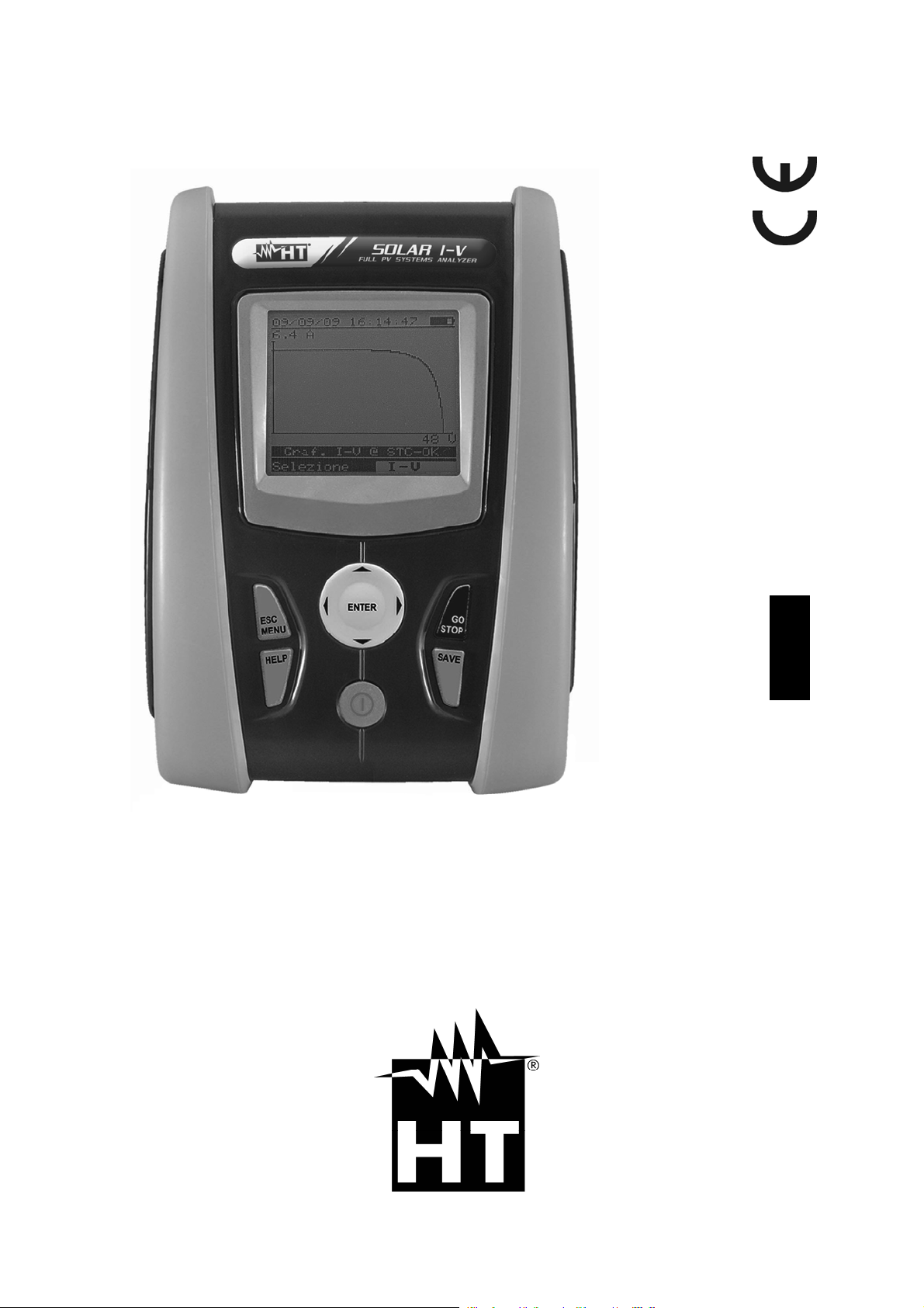
User manual
I-V400 - SOLAR I-V
Copyright HT ITALIA 2012 Release EN 1.05 - 28/05/2012
Page 2

Page 3

I-V400 - SOLAR I-V
Table of contents:
1. SAFETY PRECAUTIONS AND PROCEDURES .......................................................... 3
1.1. Preliminary instructions ..................................................................................................... 3
1.2. During use ......................................................................................................................... 4
1.3. After use ............................................................................................................................ 4
1.4. Overvoltage categories - Definitions ................................................................................. 4
2. GENERAL DESCRIPTION ........................................................................................... 5
2.1. Introduction ........................................................................................................................ 5
2.2. Instrument features ........................................................................................................... 5
3. PREPARATION FOR USE ........................................................................................... 6
3.1. Initial checks ...................................................................................................................... 6
3.2. Instrument power supply ................................................................................................... 6
3.3. Calibration ......................................................................................................................... 6
3.4. Storage .............................................................................................................................. 6
4. DESCRIPTION OF PARTS .......................................................................................... 7
4.1. Instrument description ....................................................................................................... 7
4.2. Keyboard description ......................................................................................................... 8
4.3. Display description ............................................................................................................ 8
4.4. Initial screen ...................................................................................................................... 8
5. MAIN MENU ................................................................................................................. 9
5.1. SET – Instrument settings ................................................................................................. 9
5.1.1. General .................................................................................................................................... 9
5.1.2. Measurement units ................................................................................................................ 10
5.1.3. Date/Time ............................................................................................................................... 10
5.1.4. Remote unit ............................................................................................................................ 11
5.1.5. Irradiance ............................................................................................................................... 12
5.1.6. DC Clamp (only SOLAR I-V) ................................................................................................. 12
5.2. EFF – SETTINGS FOR TESTING PV SYSTEMS (ONLY SOLAR I-V) ........................... 13
5.2.1. Settings for PV systems with single-MPPT inverter - single-phase AC output ..................... 13
5.2.1.1. Instrument settings ........................................................................................................................... 13
5.2.1.2. PV plant parameters ........................................................................................................................ 14
5.2.2. Settings for PV with single/multi MPPT inverter – single/three phase AC output .......................... 15
5.2.2.1. Instrument settings ........................................................................................................................... 15
5.2.2.2. PV plant parameters ........................................................................................................................ 16
5.2.2.3. MPP300 status ................................................................................................................................ 17
5.2.3. Selection of the compensation relationship of temperature effects ....................................... 18
5.3. DB – Module database .................................................................................................... 19
5.3.1. How to define a new PV module ............................................................................................ 20
5.3.2. How to modify a PV module ................................................................................................... 21
5.3.3. How to delete a PV module ................................................................................................... 21
6. HOW TO OPERATE ................................................................................................... 22
6.1. Testing PV systems (only SOLAR I-V) ............................................................................ 22
6.1.1. Testing of PV systems with single-MPPT inverter - single-phase AC output ........................ 23
6.1.2. Test PV systems with single/multi-MPPT inverter – single/three-phase AC output ................... 27
6.2. I-V curve measurement ................................................................................................... 33
6.2.1. I-V curve measurement by use of instrument ........................................................................ 33
6.2.2. I-V curve measurement by use of remote unit SOLAR-02 .................................................... 37
6.2.2.1. I-V curve test by remote unit SOLAR-02 in RF connection .............................................................. 37
6.2.2.2. I-V curve test by remote unit SOLAR-02 in synchro recording ......................................................... 41
6.2.3. Meaning of measurement results .......................................................................................... 46
6.2.4. Serial resistance Rs ............................................................................................................... 47
6.2.4.1. Serial resistance Rs measurement .................................................................................................. 47
6.3. Quick Check on PV modules and strings (IVCK) ............................................................ 50
6.3.1. General information ............................................................................................................... 50
6.3.2. Preliminary settings ................................................................................................................ 51
6.3.3. Fast check IVCK without irradiance measurement ................................................................ 52
6.3.4. Fast check IVCK with irradiance measurement ..................................................................... 54
6.3.5. Reset Media ........................................................................................................................... 56
6.4. List of display messages ................................................................................................. 57
EN - 1
Page 4

I-V400 - SOLAR I-V
7. STORING DATA ......................................................................................................... 58
7.1. Saving test results of PV checks (only SOLAR I-V) ........................................................ 58
7.2. Saving test results of I-V curve test ................................................................................. 58
7.3. Managing the results ....................................................................................................... 59
7.3.1. Recall data of PV checks at display (solo SOLAR I-V) .......................................................... 59
7.3.2. Recall data of I-V curve tests at display ................................................................................. 60
7.3.2.1. View data – Numerical screens ........................................................................................................ 61
7.3.2.2. View data – Graphic screens of I-V curve ........................................................................................ 62
7.3.2.3. View data – Graphic screens of power ............................................................................................. 63
7.3.3. Delete data ............................................................................................................................. 64
8. CONNECTING THE INSTRUMENT TO A PC ............................................................ 65
9. MAINTENANCE .......................................................................................................... 66
9.1. General ............................................................................................................................ 66
9.2. Battery replacement ........................................................................................................ 66
9.3. Instrument cleaning ......................................................................................................... 66
9.4. End of life ........................................................................................................................ 66
10. TECHNICAL SPECIFICATIONS ................................................................................. 67
10.1. Yield test technical feratures (only SOLAR I-V) .............................................................. 67
10.2. I-V test technical features (I-V and IVCK) ....................................................................... 68
10.3. Safety specifications ........................................................................................................ 68
10.3.1. General .................................................................................................................................. 68
10.4. General characteristics .................................................................................................... 69
10.5. Environment conditions ................................................................................................... 69
10.6. Accessories ..................................................................................................................... 69
11. APPENDIX ................................................................................................................. 70
11.1. Testing photovoltaic systems .......................................................................................... 70
11.2. Notes on MPPT (Maximum Power Point Tracker) .......................................................... 71
11.3. Theoretical aspects of the I-V curve measurement ......................................................... 72
11.3.1. Theoretical aspects of Rs measurement ............................................................................... 72
12. SERVICE .................................................................................................................... 73
12.1. Warranty conditions ......................................................................................................... 73
12.2. Service ............................................................................................................................ 73
EN - 2
Page 5

I-V400 - SOLAR I-V
1. SAFETY PRECAUTIONS AND PROCEDURES
The word “instrument” in this manual means generically both the model I-V400 and the
model SOLAR I-V except notation specifically indicated. This instrument has been
designed in compliance with directives IEC/EN61010-1 regarding electronic measuring
instruments. Before and while measuring, carefully follow the instructions below:
Do not perform voltage or current measurements in humid environments
Do not perform measurements near explosive gas or material and fuels or in dusty
environments
Avoid contact with the circuit tested if no measurement is being performed
Avoid contact with exposed metal part s, test terminals not in use, circuit s, etc.
Do not perform any measurement if instrument anomalies are detected, such as
deformations, breaks, leakage of substances, no display reading, etc.
Only use original HT accessories
In this manual, following symbols are used:
CAUTION: Follow the instructions given in this manual; improper use may
damage the instrument, its components or create dangerous situations for the
operator
High voltage: risk of electrical shock
Double insulation
DC voltage or current
AC voltage or current
Ground reference
1.1. PRELIMINARY INSTRUCTIONS
This instrument has been designed for use in the environmental conditions specified in
§ 10.5. Do not use in different environmental conditions.
The instrument may be used for measuring of VOLTAGE and CURRENT in CAT II
1000V DC or CAT III 300V to ground. Do not use on systems exceeding the limit
values specified in § 10.1 and § 10.2
We recommend to follow the ordinary safety rules aimed at: your protection against
dangerous currents, the instrument’s protection against improper use.
Only the accessories provided with the instrument guarantee compliance with safety
standards. They must be in good conditions and must be replaced, if necessary, with
identical models.
Check that batteries are correctly inserted.
Before connecting the test cables to the circuit being tested, check that the desired
function has been selected.
EN - 3
Page 6

I-V400 - SOLAR I-V
1.2. DURING USE
We recommend to carefully read the following recommendations and instructions:
CAUTION
Failure to comply with the CAUTIONs and/or instructions may damage the
instrument and/or its components or cause dangers to the operator.
The symbol “ ” indicates the charge level. When there are five bars, it
means that batteries are fully charged; a decrease in the number of bars
down to “ ” indicates that the batteries are almost low. In this case,
interrupt tests and replace the batteries according to the indications given
in § 9.2. The instrument is capable of keeping data stored even
without batteries.
1.3. AFTER USE
When measuring operations are completed, turn off the instrument by pressing and
holding the ON/OFF key for a few seconds. Should the instrument remain unused for a
long time, remove batteries and follow the indications given in § 3.4.
1.4. OVERVOLTAGE CATEGORIES - DEFINITIONS
Standard IEC/EN61010-1 (Safety requirements for electrical equipment for measurement,
control and laboratory use, Part 1: General requirements) defines what a measurement
category (usually called “overvoltage category”) is. At § 6.7.4: Measuring circuits it quotes:
Circuits are divided into the following measurement categories:
Measurement category IV is for measurements performed at the source of the low-
voltage installation.
Examples are electricity meters and measurements on primary overcurrent protection
devices and ripple control units.
Measurement category III is for measurements performed in the building installation.
Examples are measurements on distribution boards, circuit breakers, wiring, including
cables, bus-bars, junction boxes, switches, socket-outlets in the fixed installation, and
equipment for industrial use and some other equipment, for example, stationary motors
with permanent connection to fixed installation.
Measurement category II is for measurements performed on circuits directly
connected to the low voltage installation.
Examples are measurements on household appliances, portable tools and similar
equipment.
Measurement category I is for measurements performed on circuits not directly
connected to MAINS.
Examples are measurements on circuits not derived from MAINS, and specially
protected (internal) MAINS-derived circuits. In the latter case, transient stresses are
variable; for that reason, the norm requires that the transient withstand capability of the
equipment is made known to the user.
EN - 4
Page 7

I-V400 - SOLAR I-V
2. GENERAL DESCRIPTION
2.1. INTRODUCTION
The instrument was designed to perform complete yield test on single-phase (and threephase if combined with optional accessory MPP300) PV installations with calculations of
efficiencies (only SOLAR I-V) and to perform all I-V curve tests on single m odules (panels) or
complete strings of photovoltaic (PV) plants in order to verify the reference parameters given by
the manufacturers. Therefore, the meter is an ideal solution for troubleshooting any PV
installation
2.2. INSTRUMENT FEATURES
The instrument can perform the following tests:
Check on Single phase PV installations (EFF - only SOLAR I-V)
DC/AC TRMS voltage and current measurements
DC/AC power measurement
Solar irradiation [W/m
Module and environ. temp. measurement by means of probe connect to SOLAR-02
Use of compensation relationships on PDC measurements
Immediate evaluation of result OK/NO of a test
Checks with programmable IP from 5s to 60min
Testing of single/three-phase PV systems (MPP – only SOLAR I-V + opt. acc. MPP300)
Measurement of 3 DC voltages and currents
Measurement of DC string power and total DC power
Measurement of 3 AC TRMS voltages and currents
Measurement of total AC power
Measurement of irradiation [W/m2] by means of a reference cell connected to unit SOLAR-
02
Module and environ. temp. measurement by means of probe connect to SOLAR-02
Application of compensation relationships to DC efficiency.
Immediate evaluation of result OK/NO of a test
Parameter recording of a PV system with 5s to 60min programmable IP
I-V Curve measurement
Voltage, current, power measurement of PV module/string up to 1000V DC, 10 A DC
PV module/string temperature measurement
Irradiance measurement [W/m2] by using reference cell
Numerical and graphical results of I-V curve with 4-wire method
Comparison of results with standard conditions (STC) and OK/NO final response
Serial resistance measurement of PV module
Internal customizable database for definition up to 30 PV modules
Internal memory for saving test and Optical/USB interface for PC connection
Quick Check (IVCK)
Fast test on PV modules and strings of voltage and current up to 1000V DC, 10A
Immediate evaluation (OK/NO) of test results
The instrument has an innovative electronic function selector to simply set operations with
internal parameters, a backlit display, the contrast adjustment and a HELP key in order to
give a valid help to the operator during the meter’s connection to the plants. An
enable/disable AutoPowerOFF feature is available after about 5 minutes of idleness.
2
] measurement by use of reference cell connected to unit SOLAR-02
EN - 5
Page 8

I-V400 - SOLAR I-V
3. PREPARATION FOR USE
3.1. INITIAL CHECKS
Before shipment, the instrument’s electronics and mechanics have been carefully checked.
All possible precautions have been taken to have the instrument delivered under optimal
conditions. However, we recommend to rapidly check the instrument in order to detect
possible damage occurred during transport. Should you detect anomalies, please
immediately contact the dealer.
It is also recommended to check that the package contains all parts indicated in § 10.6. In
case of discrepancies, please contact the dealer. Should it be necessary to return the
instrument, please follow the instructions given in § 12.
3.2. INSTRUMENT POWER SUPPLY
The instrument is battery supplied. For battery type and life, see § 10.4.
The symbol “ ” indicates the charge level. When there are five bars next to the battery
symbol, it means that batteries are fully charged; a decrease in the number of bars down
to “ ” indicates that the batteries are almost low. In this case, interrupt tests and
replace the batteries according to the indications given in § 9.2.
The instrument is capable of keeping data stored even without batteries.
The instrument is provided with advanced algorithms to maximize the batteries’ life.
During instrument operation, a further short pressing of the key turns on the display’s
backlighting (if battery voltage level is high enough). In order to save battery efficiency,
backlighting automatically turns off after approx. 30 seconds.
A frequent use of back lighting reduces the batteries’ life
3.3. CALIBRATION
The instrument’s technical specifications are those described in this manual. Its
performance is warranted for one year (12 months) from the date of purchase.
3.4. STORAGE
In order to guarantee precise measurements, after a long period of the instrument’s
storage under extreme environmental conditions, wait until it recovers its normal conditions
(see the environmental specifications listed in § 10.5).
EN - 6
Page 9

I-V400 - SOLAR I-V
4. DESCRIPTION OF PARTS
4.1. INSTRUMENT DESCRIPTION
CAPTION:
1. Inputs
2. Display
3. Connector for opto insulated cable
4. Arrows/ENTER key
5. GO/STOP key
6. SAVE key
7. ON/OFF key
8. HELP / key
9. ESC/MENU key
Fig. 1: Description of the front part of the instrument
CAPTION:
1. Input for irradiance probe (I-V) / DC
transducer clamp (EFF – only
SOLAR I-V)
2. Input for auxiliary temperature probe
(I-V) / AC transducer clamp (EFF –
only SOLAR I-V)
3. C1, C2 inputs for current
measurement (I-V) / voltage
measurement (EFF – only SOLAR IV)
4. P1, P2 inputs for voltage
measurement (I-V) / AC voltage
(EFF – only SOLAR I-V)
Fig. 2: Description of the upper part of the instrument
CAPTION:
1. Connector for opto insulated cable
connection
Fig. 3: Description of the instrument’s side
EN - 7
Page 10
I-V400 - SOLAR I-V
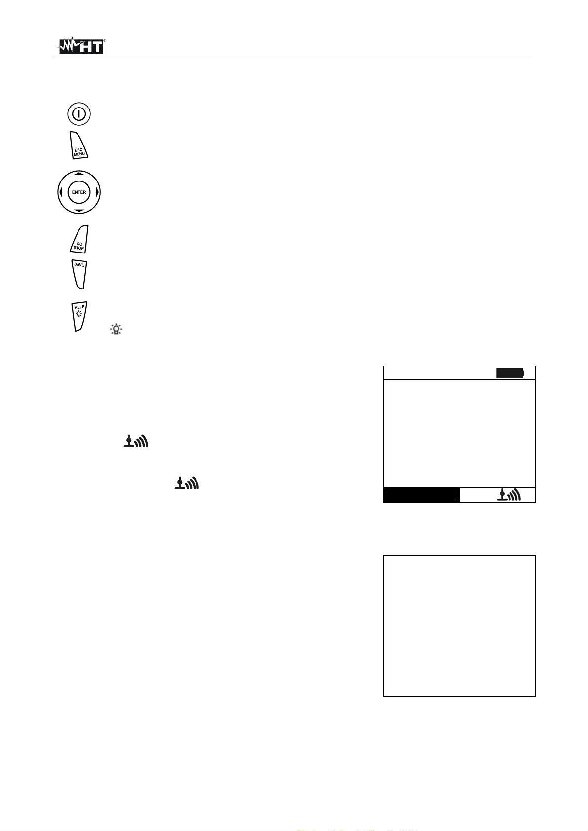
4.2. KEYBOARD DESCRIPTION
The keyboard includes following keys:
ON/OFF key to switch on/off the instrument
ESC/MENU key to exit the selected menu without confirming and to activate
menu management
keys to move the cursor through the different screens in order to
select the desired programming parameters
ENTER key to confirm the modifications and the selected programming
parameters and to select the function from the menu
GO/STOP key to start measurements
SAVE key to save the measured values
HELP key (long pressure) to display an indicative outline of the connections
between the instrument and the system being tested in the function set
key (short pressure) to turn on the display’s backlighting
4.3. DISPLAY DESCRIPTION
The display is a graphic module with a resolution of 128 x 128
dots. The display’s first line indicates the system date/hour
and the battery charge indicator.
In the bottom part the functionality of ENTER key and the
active mode is displayed
The symbol indicates the presence of an active radio
connection with the selected remote unit (SOLAR-02 or
MPP300).
The flashing symbol indicates that the instrument is
currently searching for a radio connection with the selected
remote unit (SOLAR-02 or MPP300).
4.4. INITIAL SCREEN
When turning on the instrument, the instrument displays the
initial screen for a few seconds. It displays the following:
The instrument’s model (I-V 400 or SOLAR I-V)
The manufacturer’s name
Internal module for RF connection is activated (RF) (only
I-V400)
The serial number (SN:) of the instrument
The firmware version (FW:) in the instrument's memory
The date of the last calibration (Calibration date:)
Then, the instrument switches to the last function selected.
15/05/10 15:34:26
Selection
I – V
SOLAR
I-V
HT
RF SN: 12345678
FW: 5.03
Calibration date:
09/05/2011
EN - 8
Page 11

I-V400 - SOLAR I-V
5. MAIN MENU
Pressing the MENU/ESC key in any allowable condition of
the instrument displays the main menu screen, in which the
instrument may be set, the saved measures can be displayed
and the desired measuring function may be set (item EFF
only appears for instrument SOLAR I-V).
Select by cursor the desired options and confirm by pressing
ENTER
5.1. SET – INSTRUMENT SETTINGS
Move the cursor to SET by means of the arrow keys (,)
and confirm with ENTER. Subsequently, the displays shows
the screen which provides access to the various instrument’s
settings.
The settings will remain valid also after switching off the
instrument
5.1.1. General
1. Move the cursor to “General” by means of the arrow keys
(,) and confirm with ENTER
2. The displays shows the screen which allows:
Setting the instrument language
Setting the enable/disable of auto power off
Adjusting the contrast of display
Enabling the acoustic signal when pressing a key.
3. By means of the arrow keys (,) and select the desired
option by means of the arrow keys (,)
4. Confirm with SAVE and the “Data saved” message is
displayed for a while. Press the ESC/MENU key to exit
without saving and to go back to the previous screen
15/05/10 15:34:26
I - V
I-V Test
EFF Yield Test
SET
Settings
DB
Modules
MEM
Data Recall
PC
PC connection
ENTER to select.
MENU
15/05/10 15:34:26
General
Meas. Unit
Date and Time
Remote Unit/Solarim.
Irradiance
DC Clamp
ENTER to select.
SET
15/05/10 15:34:26
Language : English
Autopoweroff :NO
Contrast :10
Key Beep :NO
SAVE to store data
SET
EN - 9
Page 12

I-V400 - SOLAR I-V
5.1.2. Measurement units
This § allows setting the default measurement units of some internal parameters included
in the database (DB) for the management of PV modules (§ 5.3)
1. Move the cursor to “Meas. Unit” by means of the arrow
keys (,) and confirm with ENTER.
2. The display shows the screen which allows selecting the
measurement units of parameters shown by the meter.
15/05/10 15:34:26
Parameter
3. Press ESC/MENU to exit without saving any setting.
4. Move the cursor to “Parameter” by means of the arrow
keys (,) and confirm with ENTER.
5. The display shows the screen which allows selecting the
measurement units of typical parameters of the modules:
Alpha possible selection: “%/°C” and “mA/°C”
Beta possible selection: “%/°C” and “mV/°C”
Gamma possible selection: “%/°C” and “W/°C”
Tolerance possible selection: “%” and “W”
6. Set the desired units by means of the arrow keys (,).
7. Confirm with SAVE and the “Saved data” message is
displayed for a while. Press ESC/MENU key to exit without
saving and to go back to the previous screen.
5.1.3. Date/Time
1. Move the cursor to “Date/Time” by means of the arrow
keys (,) and confirm with ENTER
2. The display shows the screen which allows setting the
system date/time both in the European (EU) or USA (US)
format.
3. Set the values by means of the arrow keys (,).
4. Confirm with SAVE and the “Saved data” message is
displayed for a while. Press ESC/MENU key to exit without
saving and to go back to the previous screen.
ENTER to select
15/05/10 15:34:26
Alpha
Beta
Gamma
Tolerance
15/05/10 15:34:26
Year
Month
Day
Hour
Minute
Format
: mA/°C
: mV/°C
: W/°C
: %
SAVE to store data
: 2009
: 06
: 15
: 09
: 53
: EU
SAVE to store data
MENU
SET
SET
EN - 10
Page 13

I-V400 - SOLAR I-V
Alp
5.1.4. Remote unit
This section allows selecting the type of remote unit to be used (if available) and setting
the values of typical parameters (Sensitivity and Alpha) of the reference irradiance cell
supplied with the meter. The values of these parameters, which are printed on the
back label of the cell, depend on the type of PV modules on test.
1. Move the cursor to “Remote unit” by means of the arrow
keys (,) and confirm with ENTER
2. The display shows the screen which allows:
Select the type of remote unit to be used for testing PV
systems (only for SOLAR I- V):
15/05/10 15:34:26
Remote U EFF MPP300
Remote U I-V: : NO
Sens. : 31.0 mV/kW/m2
ha : 0.060 %/°C
o NO: Remote unit disabled
o SOLAR: Use of SOLAR-02
o MPP300: Use of MPP300 (optional)
Enable/disable the use of the remote unit SOLAR-02 for
I-V measurements (opt. for I-V 400). In case the use of
SAVE to store data
SET
the remote unit has not been enabled, it will be possible
to set the sensitivity values (sens.) of the reference cell
provided, expressed in “mV/kW*m-2”, and of the Alpha
parameter.
3. Set the value by means of the arrow keys (,)
4. Confirm with SAVE and the “Saved data” message is
displayed for a while. Press ESC/MENU key to exit without
saving and to go back to the previous screen
CAUTION
For EFF measurements (testing of PV systems – only SOLAR I-V), disabling
the remote unit entails:
The impossibility of carrying out Irradiation and Temperature
measurements by means of unit SOLAR-02
The impossibility of using the unit MPP300 (if available)
Consequently, it will be impossible to obtain a result for the test carried out.
EN - 11
Page 14
I-V400 - SOLAR I-V
5.1.5. Irradiance
1. Move the cursor to “Irradiance” by means of the arrow
keys (,) and confirm with ENTER.
2. The display shows the screen with the options: “ Irr min
IV” which allows to set the minimum threshold of
15/05/10 15:34:26
Irr min IV
Irr min EFF
: 0 W/m2
: 600 W/m2
measured irradiance expressed in W/m2, used by meter as
reference during the I-V curve measurements and “Irr min
EFF” (only SOLAR I-V) which allows to set the minimum
threshold of measured irradiance expressed in W/m2, used
by meter as reference during the check PV efficiency
measurements
SAVE to store data
SET
3. Set the value by means of the arrow keys (,). The
accuracy indicated in this manual is granted under
condition indicated in § 10.1 and § 10.2. In I-V curve
measurement the value is set within the 0 800 W/m
interval while 400 800 W/m2 for the PV check
2
operations (only SOLAR I-V)
4. Confirm with SAVE and the “Saved data” message is
displayed for a while. Press ESC/MENU key to exit without
saving and to go back to the previous screen.
CAUTION
The “0 W/m2” setting for parameter “Min Irr IV” allows carrying out I-V
measurements without the following conditions being checked:
Connection of reference cell to input IRR of the instrument
Unsteady irradiation values
Number of modules consistent with the measured open circuit voltage
5.1.6. DC Clamp (only SOLAR I-V)
This option allows setting a possible correction factor K for the DC clamp, in order to improve
current measurement. If present, the correction factor is indicated on the rear label of the clamp
itself, indicated as:
K= X.xxx
In case no label is present, set k = 1.000
1. Move the cursor to “DC Clamp” by means of the arrow
keys (,) and confirm with ENTER
2. The item: “DC clamp k” is shown at display to set the
corrective factor in a interval within 0.950 and 1.050. Set
15/05/10 15:34:26
DC clamp k
: 1.000
the value by means of the arrow keys (, )
3. Confirm with SAVE and the “Saved data” message is
displayed for a while. Press ESC/MENU key to exit without
saving and to go back to the previous screen
SAVE to store data
SET
EN - 12
Page 15
I-V400 - SOLAR I-V
5.2. EFF – SETTINGS FOR TESTING PV SYSTEMS (ONLY SOLAR I-V)
Further in this manual, the acronym MPPT (Multiple Power Point Tracker) shall indicate
the characteristic of the DC/AC converter (inverter), capable of maximizing the DC power
which can be taken from the photovoltaic field. See § 11.2 for further details.
5.2.1. Settings for PV systems with single-MPPT inverter - single-phase AC output
Check beforehand the settings made in MENUSETRemote Unit and check that you
have selected “SOLAR” as setting for parameter “R. unit”.
5.2.1.1. Instrument settings
1. Press MENU key, move the cursor to “EFF” by means of
the arrow keys (,) and confirm with ENTER. The
screen with the values of electrical parameters relative to
PV generator is displayed
15/05/10 15:34:26
Prp - - -
Irr - - - W/m2
Pnom 0.000 kW
Tc - - - °C
Te - - - °C
Pdc 0.0 kW
Vdc 0.000 V
Idc 0.0 A
ndc - - -
GO – Start rec
Select
EFF
2. Press ENTER key. The options Set PV plant and Set
Instrum. are displayed
3. By means of the arrow keys (,) to select Set Instrum.
and confirm with ENTER. The herewith screen is shown:
15/05/10 15:34:26
PRp - - -
Irr - - - W/m2
Pnom 0.000 kW
Tc - - - °C
Te - - - °C
Pdc 0.0 kW
Vdc 0.000 V
Idc 0.0 A
ndc - - -
Set PV plant
Set Instrum.
Select
EFF
4. By means of the arrow keys (,) the herewith
parameters are set:
IP (integration period) used by meter during yield test
recording. The values I 5s, 10s, 30s, 60s, 120s, 300s,
600s, 900s, 1800s, 3600s are selectable
15/05/10 15:34:26
IP
FS DC clamp
FS AC clamp
: 5 s
: 1000 A
: 1000 A
The full scale (FS) of DC clamp used on DC current
measurement with selectable value within 1A 3000A
The full scale (FS) of AC clamp used on AC current
measurement with selectable value within 1A 3000A
5. Press the SAVE key to save the settings made; the
SAVE to store data
EFF
message “Data saved” will be displayed for a few
seconds. Press the ESC/MENU key to exit without saving
and go back to the previous screen.
EN - 13
Page 16

I-V400 - SOLAR I-V
5.2.1.2. PV plant parameters
1. Press MENU key, move the cursor onto EFF by using the
arrow keys (,) and confirm with ENTER. The display
shows the values of the output electrical parameters of
the photovoltaic generator (DC side).
2. Press the ENTER key. The instrument shows the
following options: “Set PV plant“ and “Set Instrum“.
3. Use the arrow keys (,) to select “Set PV plant” and
confirm with ENTER. The instrument shows the following
screen:
4. By means arrow keys ( , ) the herewith parameters
are set:
Pmax maximum nominal power of the PV
installation expressed in kW
Gamma coefficient of variation of power with the
temperature, standard parameter of PV module
(range: -0.3 -0.5%/°C typical)
Noct nominal working temperature of a PV cell,
standard parameter of PV module (range: 42 48°C
typical)
Te, Tc set of default values of environmental
temperature and PV module temperature. These
values are considered by the meter only without the
auxiliary probe connected to emote unit SOLAR-02
Corr. Type set the corrective term Ptpv for DC
efficiency calculation and for maximum DC efficiency
visualization (see § 5.2.3)
15/05/10 15:34:26
PRp - - -
Irr - - - W/m2
Pnom 0.000 kW
Tc - - - °C
Te - - - °C
Pdc 0.0 kW
Vdc 0.000 V
Idc 0.0 A
ndc - - -
GO – start rec
Select
EFF
15/05/10 15:34:26
Prp - - - W/m2
Irr - - - W/m2
Pnom 0.000 kW
Tc - - - °C
Te - - - °C
Pdc 0.0 kW
Vdc 0.000 V
Idc 0.0 A
ndc - - -
Set PV plant
Set Instrument
Select
EFF
15/05/10 15:34:26
Pmax
: 3.500 kW
Gamma
Noct
Te
Tc
Corr. Type
: 0.45 %/°C
: 45 °C
: 40 °C
: 45 °C
:
T. Env
SAVE to store data
EFF
EN - 14
Page 17

I-V400 - SOLAR I-V
5.2.2. Settings for PV with single/multi MPPT inverter – single/three phase AC output
See § 11.2 for further details about the meaning of MPPT. This mode requires unsing the
remote unit MPP300 (optional). Check beforehand the settings made in
MENUSETRemote Unit and check that you have selected “MPP300” as setting for
parameter “R. unit”.
5.2.2.1. Instrument settings
1. Press the MENU key, position the cursor onto EFF by
using the arrow keys (,) and confirm with ENTER.
The display shows the screen here to the side, which
contains the global parameters of the system.
15/05/10 15:34:26
PRp - - -
Irr - - - W/m2
Pnom 150.0 kW
Tc - - - °C
Te - - - °C
Pdc - - - kW
Pac - - - kW
ndc - - -
nac - - -
GO - start Rec
Select
MPP
2. Press the ENTER key. The instrument shows the
following options: MPP300 status, System Par. and
Instrument settings.
3. Use the arrow keys (,) to select “Instrument
settings” and confirm with ENTER. The instrument shows
the following screen:
15/05/10 15:34:26
PRp - - -
Irr - - - W/m2
Pnom 150.0 kW
Tc - - - °C
Te - - - °C
Pdc - - - kW
Pac - - - kW
ndc - - -
nac - - -
MPP300 Status
Set PV plant
Set Instrum.
Select
MPP
4. By using the arrow keys ( , ) it is possible to set:
the integration period (IP) which can be used by the
instrument when testing the parameters of a PV
system. The following values can be selected: 5s, 10s,
30s, 60s, 120s, 300s, 600s, 900s, 1800s, 3600s
The FS of the DC clamp used for measuring DC
current with value selectable between 1A 3000A
15/05/10 15:34:26
IP
FS DC clamp:
FS AC clamp:
Clamp Type:
Dc inputs
Ac sytem
: 5 s
1000 A
1000 A
STD
1+2+3
3phase
The FS of the AC clamp used for measuring AC
current with value selectable between 1A 3000A
The type of AC clamp used: STD (standard) or FLEX
(flexible clamp)
The number of DC inputs to be used for measuring:
SAVE to store data
MPP
1, 1+2, 1+2+3
The type of AC electrical system: SINGLE, 4 wires
5. Press the SAVE key to save the settings made; the
message “Data saved” will be displayed for a few
seconds. Press the ESC/MENU key to exit without saving
and go back to the previous screen.
EN - 15
Page 18

I-V400 - SOLAR I-V
C
5.2.2.2. PV plant parameters
1. Press MENU key, position the cursor onto EFF by using
the arrow keys (,) and confirm with ENTER. The
display shows the screen here to the side, which contains
the global parameters of the system.
2. Press the ENTER key. The instrument shows the
following options: MPP300 status, Set PV plant. and Set
Instrum.
3. Use the arrow keys (,) to select “Set PV plant” and
confirm with ENTER. The instrument shows the following
screen:
4. By using the arrow keys ( , ) it is possible to set:
Pmax maximum rated power of PV installation
expressed in kW
Range coefficient of power variation with
temperature, characteristic parameter of PV modules
(typically in range: -0.3 -0.5%/C)
Noct rated operating temperature of the cell,
characteristic parameter of PV modules (typically in
range: 42 48°C)
Te, Tc setting of default values of environmental
and PV module temperatures. These values are taken
into consideration by the instrument only when probe
is not connected to unit SOLAR-02
Corr. Type Setting of the compensation
relationship on the calculation of Pdc power and the
maximization of DC performance (see § 5.2.3)
15/05/10 15:34:26
PRp - - -
Irr - - - W/m2
Pnom 150.0 kW
Tc - - - °C
Te - - - °C
Pdc - - - kW
Pac - - - kW
ndc - - -
nac - - -
GO – start rec.
Select
MPP
15/05/10 15:34:26
PRp - - -
Irr - - - W/m2
Pnom 0.000 kW
Tc - - - °C
Te - - - °C
Pdc 0.0 kW
Vdc 0.000 V
Idc 0.0 A
ndc - - -
MPP300 status
Set PV plant
Set instrum.
Select
MPP
15/05/10 15:34:26
Pmax
Gamma
Noct
Te
Tc
orr.Type.
: 0.45 %/°C
: 3.500 kW
: 45 °C
: 40 °C
: 45 °C
:
T. Env
SAVE to store data
MPP
EN - 16
Page 19

I-V400 - SOLAR I-V
5.2.2.3. MPP300 status
If SOLAR I-V is near MPP300, the general parameters of MPP300 may be displayed.
1. Position the cursor onto EFF by using the arrow keys
(,) and confirm with ENTER. The display shows the
screen here to the side, which contains the global
parameters of the system.
15/05/10 15:34:26
PRp - - -
Irr - - - W/m2
Pnom 150.0 kW
Tc - - - °C
Te - - - °C
Pdc - - - kW
Pac - - - kW
ndc - - -
nac - - -
GO – start rec.
Select
MPP
2. Press the ENTER key. The instrument shows the
following options: MPP300 status, Set PV plant and Set
Instrum.
3. Use the arrow keys (,) to select “MPP300 status”
and confirm with ENTER. The instrument shows the
screen here to the side, which indicates the main general
parameters of the instrument.
15/05/10 15:34:26
Power supply P.Sup.
Battery In use
Charge 99%
SOLAR-02
detected
Version 1.01
SN 11010030
MPP300 status
SI
Set PV plant
Set instrum.
Select
MENU
EN - 17
Page 20

I-V400 - SOLAR I-V
5.2.3. Selection of the compensation relationship of temperature effects
This option allows selecting the relationship to be used to correct the measurements
performed according to the modules’ temperature. The following correction modes are
available:
- T.mod.: Correction factor Rfv2 related to PV module Temp. (Italian guideline CEI-82-25)
- T.env: Correction factor Rfv2 related to environment Temp. (Italian guideline CEI-82-25)
- ndc: PRp (Performance ratio for active power) corrected by PV module Temp.
CAUTION
If it’s performed a test according to Italian guideline it is recommended to select
Corr.
Type
T.mod.
T.amb.
“T.env.” correction
Temperature (Tcel) PRp calculation Ref.
asTmodule_MeTcel
R
Irr
20TambTcel NOCT
800
fv2
PRp
40)-(Tcel- 1
Rfv
-
2
100
G
P
ca
G
p
STC
P
n
C)40Tcel (if 1
C)40Tcel (if
CEI
82-25
25
P
ca
P
n
W/m
W/m
kW
kW
- - -
2
2
C%/
C%/
G
dc
where:
Symbol Description Meas. unit
G
p
G
STC
P
n
P
ca
NOCT Normal Operating Cell Temperature (@ 800W/m2, 20°C, AM=1.5, vel. Aria =1m/s).
Irradiance on PV module surface
Standard Irradiance = 1000
Nominal Power = sum of all power module (Pmax ) included in the part of PV plant under test
AC Active Power measured
Thermal Coefficient factor
2Rfv
Absolute value of Pmax thermal coefficient
asTmodule_MeTcel
PRp
G
STC
p
1
100
T
cel
For further details see § 11.1
EN - 18
Page 21

I-V400 - SOLAR I-V
5.3. DB – MODULE DATABASE
The meter allows defining up to 30 different PV modules, further to a DEFAULT situation
(not editable and not erasable) which can be used as reference case when no piece of
information about the module under test is available.
The parameters which can be set, with reference to 1 module, are described below in
Table 1 together with their range, resolution and validity condition.
Symbol Description Range Resolution Condition
Nms Number of modules for string
Pmax Maximum nominal power of module
Voc Open voltage
Vmpp Voltage on point of maximum power
Isc Short circuit current
Impp Current on point of maximum power
Toll -
Toll +
Alpha Isc temperature coefficient
Beta Voc temperature coefficient
Gamma Pmax temperature coefficient
NOCT Nominal working temperature of cell
Tech. Effects due to PV technology
Rs Internal serial resistance
Negative tolerance for Pmax provided
by the module manufacturer
Positive tolerance for Pmax provided
by the module manufacturer
1 50
50 3200W
15.00 99.99V
100.0 320.0V
15.00 99.99V
100.0 320.0V
0.5 9.99A
0.5 9.99A
0% 25.0%
0 99W
0 25%
0 99W
-0.1000.100%/°C
-9.99 9.99mA/°C
-0.99 -0.01%/°C
-0.999 0.001V/°C
-0.99 -0.01%/°C
0 100°C
STD (standard)
CAP(capacitive eff.)
0.00 10.00 0.01
1
1W
0.01V
0.1V
0.01V
0.1V
0.01A
0.01A
0.1%
1
0.1%
1
0.001%/°C
0.01mA/°C
0.01%/°C
0.001V/°C
0.01%/°C
1°C
max
100*Tol-/Pnom< 25
100*Tol+/Pnom< 25
0.1*Alpha / Isc 0.1
100*Beta/Voc 0.999
IVP
mppmpp
P
max
Voc Vmpp
Voc Vmpp
Isc Impp
Isc Impp
01.0
Table 1: Typical parameters of PV modules
CAUTION
The “Tech” item is referred to the choose of the technology of the module
on test. Select the “STD” option for test on “STANDARD” PV modules or the
“CAP” option for test on higher capacitive effects PV modules (e.g. HIT/HIP
technology)
A wrong choose of the type of technology can lead to a negative outcome of
the final test
EN - 19
Page 22

I-V400 - SOLAR I-V
5.3.1. How to define a new PV module
1. Move the cursor to “DB” by means of the arrow keys
(,) and confirm with ENTER. The display shows the
screen with:
The type of selected module
The parameter associated to the module (see Table 1)
2. Select the “DEFAULT” module by means of the arrow
keys (,) and confirm with ENTER.
3. Press ENTER, select the “New” command and confirm
again with ENTER. Use the arrow keys (,) to scroll all
internal parameters.
4. By using the internal virtual keyboard it is possible to
define the name of the module (ex: SUNPOWER 210) by
means the arrow keys (,,,). Press ENTER to digit
the characters of the desired name.
5. Press the SAVE key to save the inserted name of the
module as defined or ESC/MENU key to exit without
saving.
6. Digit the value of each parameter of the defined module
(see Table 1) based on the manufacturer’s data sheet.
Move the cursor to the row of the parameter by means of
the arrow keys (,) and set the value by means of the
arrow keys (,). Press and hold (,) for a quick
setting of values.
7. Confirm with SAVE and the “Saved data” message is
displayed for a while. Press ESC/MENU key to exit
without saving and to go back to the previous screen.
CAUTION
If the value of any parameter is unknown press and hold the HELP key for
some seconds to set the default values
After pressing the SAVE key, the meter checks all the conditions shown in
Table 1 and, if one or more of these conditions do not occur, some error
messages are shown by the display (§ 6.5) and the meter does not save
the configuration before any error is solved. Solve the error condition
before saving.
15/05/10 15:34:26
Type : DEFAULT
Pmax = 185 W
Voc = 44.5 V
Vmpp = 37.5 V
Isc = 5.40 A
Impp = 4.95 A
Toll- = 0 %
Select
DB
15/05/10 15:34:26
Type : DEFAULT
Pmax = 185 W
Voc = 44.5 V
Vmpp = 37.5 V
Isc = 5.40 A
Impp = 4.95 A
Toll- = 0 %
New
Select
DB
15/05/10 15:34:26
Type :
Pmax = 185 W
Voc = 44.5 V
KEYBOARD
SUNPOWER 210
ABCDEFGHI J KLMNOP
QRST UVWXYZ- +0 123
4 5 6 7 8 9 SPACE DEL
15/05/10 15:34:26
Type : SUNPOWER 210
Pmax = 0 W
Voc = 0.0 V
Vmpp = 0.0 V
Isc = 0.00 A
Impp = 0.00 A
Toll- = 0 %
DB
EN - 20
Page 23

I-V400 - SOLAR I-V
S
210
5.3.2. How to modify a PV module
1. Select the PV module to be modified from the internal
database by means of arrow keys (,).
2. Press the ENTER key and select the “Modify” command
by means the arrow key ().
3. Confirm the selection with ENTER.
4. By using the internal virtual keyboard it is possible to
define a different name of the module by means of arrow
keys (,,,). Press ENTER to digit any character of
the desired name.
5. Press the SAVE key to save the new name of the module
as defined or to access the new setting of parameters.
6. Select the desired parameter s to be modified by means of
arrow keys (,) and change values by means of arrow
keys (,). Press and hold the (,) for a quick setting
of values. If the value of any parameter is unknown, press
and hold the HELP key for some seconds to set the
default values.
7. Confirm with SAVE and the “Saved data” message is
displayed for a while. Press ESC/MENU key to exit
without saving and to go back to the previous screen.
15/05/10 15:34:26
Type: SUNPOWER210
Pmax = 210 W
Voc = 47.70 V
Vmpp = 40.00 V
Isc = 5.75 A
New
Modify
Delete
Del. All
Select
15/05/10 15:34:26
Type: SUNPOWER210
Pmax = 185 W
Voc = 44.5 V
KEYBOARD
UNPOWER
ABCDEFGHI J KLMNOP
QRST UVWXYZ- +0 123
4 5 6 7 8 9 SPACE DEL
SAVE/ESC
15/05/10 15:34:26
Type : SUNPOWER 210
Pmax = 210 W
Voc = 47.70 V
Vmpp = 40.00 V
Isc = 5.75 A
Impp = 5.25 A
Toll- = 5 %
DB
DB
5.3.3. How to delete a PV module
1. Select the PV module to be deleted from the internal
database by means of arrow keys (,).
2. Press the ENTER key and select “Delete” command by
means of arrow key () to delete the selected module.
3. Press the ENTER key and select “Del. All” command by
means of arrow key () to delete all modules in the
database (except for “DEFAULT”).
4. Confirm the selection with ENTER or press ESC/MENU to
exit
CAUTION
It is not possible to modify or delete the “DEFAULT” PV module which is the
standard reference factory module.
EN - 21
15/05/10 15:34:26
Type: SUNPOWER210
Pmax = 210 W
Voc = 47.70 V
Vmpp = 40.00 V
Isc = 5.75 A
New
Modify
Delete
Del. All
Select
DB
Page 24

I-V400 - SOLAR I-V
6. HOW TO OPERATE
6.1. TESTING PV SYSTEMS (ONLY SOLAR I-V)
For the sake of simplicity, further in this manual, the word “string” will be used, although
often the term “photovoltaic field” would be more correct. From the point of view of the
instrument, the management of a single string or of more parallel strings (photovoltaic field)
is identical. Furthermore, the acronym MPPT (Multiple Power Point Tracker) shall indicate
the characteristic of the DC/AC converter (inverter), capable of maximizing the DC power
which can be taken from the photovoltaic field (see the § 11.2 for further details), the
acronym PRp shall indicated the Performance ratio (evaluated on active powers).
For the evaluation of the PRP only, the measurement of the DC (voltage
and current) is not strictly necessary
Conversely it is necessary if you want to evaluate the performance of the
photovoltaic section (ndc) and DC / AC conversion (nac)
Simbol Description Unit
PRp Performance Ratio (calculated through Active power)
Irr Irradiance W/m2
Pnom Total Nominal power of the PV section under test. kW
Tc Module Temperature °C
Te Environment Temperature °C
Pdc, Pdcx Total DC power measured, DC power of PV field x (x=1,2,3) kW
Pac, Pacx Total AC power measured, AC power of phase x (x=1,2,3,) kW
ndc DC efficiency
nac AC efficiency
Vdc, Vdcx DC Voltage, DC voltage of PV field x (x=1,2,3) V
Idc, Idcx DC current, DC current of PV field x (x=1,2,3) A
Vac, Vacx AC Voltage, AC voltage of PV field x (x=1,2,3) V
Iac, Iacx AC current, AC current of PV field x (x=1,2,3) A
Symbols description
CAUTION
EN - 22
Page 25

I-V400 - SOLAR I-V
6.1.1. Testing of PV systems with single-MPPT inverter - single-phase AC output
The SOLAR I-V meter (master) can perform check tests of efficiencies on single phase PV
installations by using the irradiance and temperature probes which are connected to the
remote unit SOLAR-02. This remote unit communicates with the master unit (for the
synchronization and download data operations) through a wireless radio-frequency (RF)
which is active with a maximum distance of about 1m between units.
CAUTION
The maximum voltage between C1, and C2 inputs is 1000V DC and
between P1 and P2 inputs is 265V AC rms. Do not measure voltages
exceeding the limits prescribed by this manual. Should you exceed the
voltage limits you could damage the instrument and/or its components or
endanger your safety
In order to guarantee the operator’s safety, while making the connections,
disable the system being measured by means of the switches/breakers
upstream and downstream of the DC/AC converter (inverter).
Fig. 4: Connection of meter for check on single phase PV installation
1. Check and, if necessary, set the sensitivity of the reference cell on SOLAR-02 consistently
with the type of PV modules which will be measured (please refer to the User Manual of
SOLAR-02)
2. We recommend making a preliminary evaluation of the value of irradiation on the surface of
the PV modules being tested by means of unit SOLAR-02 (operating independently) and the
reference cell
3. Switch on SOLAR I-V. Check and if necessary modify the basic settings of meter
relative to the minimum irradiance threshold, the FS of DC and AC transducer clamps,
the IP and the parameters of the PV installation on test (see § 5.1.1, §5.1.5 and §5.2)
4. In order to guarantee the operator’s safety, disable the system being measured by means of
the switches/breakers upstream and downstream of the DC/AC converter (inverter)
EN - 23
Page 26

I-V400 - SOLAR I-V
5. In case of inverters provided with more than one power tracker (MPPT), only leave the
string corresponding to the first MPPT connected, as shown in Fig . 4 . Then, it will be
necessary to repeat the operations described below by only leaving the string corresponding
to the second MPPT connected, then to the third, etc.
6. Bring SOLAR I-V and SOLAR-02 nearer (maximum distance of 1m between them). All
instruments must be switched on (see the User Manual of SOLAR-2 for further details)
7. On SOLAR I-V, press the MENU key, select the function EFF and press ENTER; wait for
the two units to start communicating with each other. This condition is highlighted by the
contemporary presence of the following indicators:
Symbol steady (not flashing) on the display of SOLAR I-V
Symbol
steady (not flashing) on the display of SOLAR-02
8. Connect the C2 and C1 inputs respectively to the positive and negative polarity of the
output string. Connect the P1 and P2 inputs to the phase and neutral conductors
respecting the colors as shown in Fig. 4
9. Connect the output connector of the DC clamp to the IDC1 input.
CAUTION
BEFORE CONNECTING THE DC CLAMPS TO THE CONDUCTORS
Switch on the clamp, check the LED indicating the status of the clamp’s
internal batteries (if present), select the correct range, press the ZERO key
on the DC clamp and check on the display of SOLAR I-V the actual zeroing
of the corresponding Idc value (values up to 0.02A are acceptable).
10. Connect the DC current clamp to the positive string output conductor by respecting
the direction of the arrow on the clamp itself as indicated in Fig. 4. Position the DC
clamp in point so far fron the inverter and avoid that the jaws stay close to the negative
conductor
11. Connect the AC current clamp to the Phase L1 conductor by respecting the direction
of the arrow on the clamp itself as indicated in Fig. 4. Position the AC clamp as far as
possible from the inverter and avoid that the jaws stay close to the neutral conductor.
Connect the output of the clamp to the IAC input of the instrument
12. Power on the system on test
EN - 24
Page 27
I-V400 - SOLAR I-V
13. The display shows the first screen containing the values
of the electrical parameters on the DC side of the inverter.
14. By means of arrow key to access to the second screen
with the values of electrical parameters of the AC side of
inverter. Before to start the recording:
Verify the symbol “ ” blinking at display which
means the search by the meter of RF connection with
the remote unit SOLAR-02
Verify that the Pac active power should be a positive
value. In the opposite case open the AC clamp and
rotate of 180 degree on the phase conductor
Verify that the AC efficiency ac = Pac / Pdc should be
a consistent value (e.g.: a situation of ac > 1 is not
physically possible)
15. With remote unit always close to the main unit press
GO/STOP key to start the recording. The “Rec. Start
waiting…” message is shown at display of main unit and the
“HOLD” message is shown at display of SOLAR-02 more
than the indication of residual time for “00” instance
16. When the “00” instant after the press of GO/STOP key is
reached, the recording starts and the units are correctly
synchronized. In these conditions the message “Rec
running…” is displayed on the main unit and the
“Recording…” message is displayed on the SOLAR-02
15/05/10 15:34:26
PRp - - -
Irr - - - W/m2
Pnom 3.500 kW
Tc 45 °C
Te 30 °C
Pdc 3.125 kW
Vdc 389 V
Idc 8.01 A
ndc - - -
GO – start rec.
Select
EFF
15/05/10 15:34:26
Pdc 3.125 kW
Vdc 389 V
Idc 8.01 A
ndc - - - °C
Pac 3.012 kW
Vac 231 V
Iac 13.03 A
nac 0.96
GO – start rec
Select
EFF
15/05/10 15:34:26
Pdc 3.125 kW
Vdc 389 V
Idc 8.01 A
ndc - - - °C
Pac 3.012 kW
Vac 231 V
Iac 13.03 A
nac 0.96
Rec. Start waiting…
Select
EFF
15/05/10 15:35:00
Pdc 3.125 kW
Vdc 389 V
Idc 8.01 A
ndc - - - °C
Pac 3.012 kW
Vac 231 V
Iac 13.03 A
nac 0.96
Rec. Running…
Select
EFF
EN - 25
Page 28
I-V400 - SOLAR I-V
971
30
0.9
17. At any time it will be possible to analyze the current
recording status by pressing the MENU key. The following
information will be shown:
starting date and time of recording
the value set for the integration period
the number of periods elapsed from the beginning
of the recording
the remaining memory capacity for recording
Press the ESC key to exit the screen
15/05/10 15:35:00
Start
14/02/00 17:18:00
Period: 5s
IP Number 61
Rec. Time 0d 1h
Rec. running
Select
MPP
18. Now it is possible to bring the unit SOLAR-02 near the PV strings to measure irradiation and
temperature by means of the relevant probes. When the distance between unit SOLAR-02
and SOLAR I-V does not allow the RF connection, on the display of SOLAR-02, the symbol
“ ” flashes for approx. 30s and then disappears, while SOLAR I-V continues searching
for the connection for approx. 1 minute.
19. Position the reference cell onto the surface of the PV modules. Please refer to the relevant
User Manual for a correct assembly.
20. Put the temperature sensor in contact with the rear side of the module and fasten it with
some tape; prevent touching it with your fingers (as this could alter the measure).
21. Wait some seconds in order to permit a stable measure by probes and then connect the
irradiation and temperature probes respectively to the inputs PYRA/CELL and TEMP
of the SOLAR-02 unit.
22. Wait for “READY” message displayed on SOLAR-02. This event indicates that the
instrument has detected some data with solar irradiation > minimum limit threshold (see
§ 5.1.5)
23. Wait at least 1 minute in order to recording more valid samples
24. Disconnect the irradiation and temperature probes from unit SOLAR-02 and bring the unit
near SOLAR I-V (max distance 1m).
25. The main unit SOLAR I-V must be in EFF mode. If there is no flashing symbol “ ”,
press key to activate the RF connection search again.
26. Press the key on SOLAR-02 to active the RF connection. On the main unit the message
“ RF connection active” is displayed
27. To stop testing, press the GO/STOP key on instrument
SOLAR I-V and confirm with ENTER that you want to stop
recording.
28. The display of SOLAR I-V will show the message
“DOWNLOAD” to indicate that the data will be transferred to
the main unit during its various phases.
29. After the automatic data transfer phase, the instrument:
Do not show any results if do not exist on the PV
installation a “stable irradiance” condition more than the
minimum irradiance threshold.
15/05/10 15:35:00
Irr
Pnom 3.500 kW
Tc 45.1 °C
Te
Pdc 3.125 kW
Pac 2.960 kW
ndc 0.86
nac
Analysis Result
Select
W/m2
.5 °C
5
EFF
Display the best performance values if during the recording, the Irradiance values
reached the “stable” condition and its values were higher than the minimum irradiance
threshold.
30. Press SAVE to save the results (see § 7.1) or ESC to exit the screen of the results and
go back to the initial screen
EN - 26
Page 29

I-V400 - SOLAR I-V
6.1.2. Test PV systems with single/multi-MPPT inverter – single/three-phase AC
output
The instrument SOLAR I-V, used together with remote units SOLAR-02 and MPP300
(optional), allows testing PV systems characterized by 1 or more strings (with the same
direction and inclination) and single-phase or three-phase output.
The remote unit MPP300 is capable of communicating with SOLAR I-V (to manage
synchronization and data download) and with the remote unit SOLAR-02 (for recording
irradiation and temperature values) via a wireless radiofrequency (RF) connection, which
is active up to a maximum distance of 1m between the units.
Fig. 5: Connection of MPP300 for testing a single-phase PV system
Fig. 6: Connection of MPP300 for testing a three-phase PV system
EN - 27
Page 30

I-V400 - SOLAR I-V
CAUTION
When SOLAR I-V is set in order to use MPP300 as a remote unit, ALL
connections relevant to electrical quantities (voltages and currents) must
be carried out on unit MPP300. SOLAR I-V must have no voltage nor
current connected to its inputs.
The maximum voltage for the inputs of MPP300 is 1000VDC between
inputs VDC1, VDC2, VDC3 and 600VAC between inputs VAC1, VAC2,
VAC3. Do not measure voltages exceeding the limits given in this manual.
Exceeding these limits could result in electrical shocks to the user and
damage to the instrument.
In order to guarantee the operator’s safety, while making the connections,
disable the system being measured by means of the switches/breakers
upstream and downstream of the DC/AC converter (inverter).
1. Check and, if necessary, set the sensitivity of the reference cell on SOLAR-02 consistently
with the type of PV modules which will be measured (please refer to the User Manual of
SOLAR-02).
2. We recommend making a preliminary evaluation of the value of irradiation on the surface of
the PV modules being tested by means of unit SOLAR-02 (operating independently) and the
reference cell
3. Switch on SOLAR I-V, check and, if necessary, change the settings relevant to the type of
remote unit, to the minimum irradiation threshold, to the full scale of the AC and DC clamps,
to the integration period and to the parameters of the system being measured (see § 5.1.4, §
5.1.5, § 5.1.6, § 5.2.2).
4. In order to guarantee the operator’s safety, disable the system being measured by means of
the switches/breakers upstream and downstream of the DC/AC converter (inverter).
5. Bring SOLAR I-V, SOLAR-02 and unit MPP300 nearer (maximum distance of 1m between
them). All instruments must be switched on (see the User Manuals of SOLAR-2 and
MPP300 for further details).
6. On SOLAR I-V, press the MENU key, select the function EFF and press ENTER; wait for
the three units to start communicating with each other. This condition is highlighted by the
contemporary presence of the following indicators:
Symbol steady (not flashing) on the display of SOLAR I-V
Symbol
steady (not flashing) on the display of SOLAR-02
MASTER and REMOTE LEDs flashing green on unit MPP300
7. Connect the VDC1(+) and VDC1(-) inputs of unit MPP300 to the output terminals of the
string, respecting the polarities and the colours indicated in Fig. 5 or Fig. 6
8. Repeat the operation described in the step above for other possible DC power trackers
to be monitored by using the VDC2 and VDC3 inputs according to the number of DC
inputs set (see § 5.2 . 1 . 1 ) .
EN - 28
Page 31

I-V400 - SOLAR I-V
0.9
9. Connect the output connector of the DC clamp to the IDC1 input of unit MPP300.
CAUTION
BEFORE CONNECTING THE DC CLAMPS TO THE CONDUCTORS
Switch on the clamp, check the LED indicating the status of the clamp’s
internal batteries (if present), select the correct range, press the ZERO key
on the DC clamp and check on the display of SOLAR I-V the actual zeroing
of the corresponding Idc value (values up to 0.02A are acceptable).
10. Insert the DC current clamp onto the positive output conductor of the string, respecting the
direction of the arrow found on the clamp itself as indicated i n Fig. 5 o r Fig. 6. Posi tion t he
clamp toroid as far as possible from the inverter and from the negative output conductor of
the string itself.
11. Repeat the operations described in the two steps above for other possible DC power
trackers to be monitored by using the IDC2 and IDC3 inputs according to the number of DC
inputs set (see § 5.2.1.1).
12. Connect the VAC1 and N inputs of unit MPP300 to the Phase and Neutral conductors
respectively, respecting the polarities and the colors indicated in Fig . 5 or F i g. 6 . In case of
three-phase systems in which no Neutral conductor is available, connect input N to earth.
13. In case of inverter with three-phase output (see settings in § 5.2.1.1), repeat the
operation described in the step above for the remaining phases by using the VAC2 and
VAC3 inputs of MPP300.
14. Connect the AC clamp to the Phase L1 conductor, respecting the direction of the arrow
found on the clamp itself as indicated in Fig . 5 or F i g . 6 . Position the clamp toroid as far as
possible from the inverter and from the Neutral conductor. Connect the clamp output to the
IAC1 input of MPP300.
15. In case of inverter with three-phase output (see settings in § 5.2.1.1), repeat the operation
described in the step above for the remaining phases by using the IAC2 and IAC3 inputs of
MPP300.
16. Restore the operation of the electrical system being measured.
17. The display of SOLAR I-V will show the values of the
general electrical parameters of the system being
measured. In particular, in this screen:
Pdc = General DC power (sum of the string powers)
Pac = AC power (if single-phase) or sum of the ac
powers (if three-phase)
We recommend checking that the values of the electrical
parameters (Pnom, Pdc, Pac) and of the ac performance
(ac) are consistent with the system being measured (e.g.:
ac > 1 is not physically acceptable).
15/05/10 15:34:26
PRp - - -
Irr - - - W/m2
Pnom 3.500 kW
Tc - - - °C
Te - - - °C
Pdc 3.125 kW
Pac 2.960 kW
ndc - - -
nac
GO – start rec
Select
5
MPP
EN - 29
Page 32

I-V400 - SOLAR I-V
0.9
0.9
18. On SOLAR I-V, press key () to access the second
screen which contains the values of the output DC
parameters of the strings according to the number of DC
inputs set (see § 5.2.1.1). In particular, in this screen:
Vdcx = DC voltage of string x
Idcx = DC current of string x
Pdx = DC power of string x.
We recommend checking that the values of the electrical
parameters (Vdc, Idc, Pdc) are consistent with the system
being measured.
19. On SOLAR I-V, press key () to access the third screen
which contains the values of the electrical parameters on
the AC side of the inverter, consistently with the settings
made in § 5.2.2 (single-phase, three-phase 4 wires). In
particular, in this screen:
Vacxy = AC voltage between Phase and Neutral (if
single-phase) or between Phases x and y (if threephase)
Iacx = AC current of phase x
Pacx = AC power of phase x
We recommend checking that the values of the electrical
parameters (Vac, Iac, Pac) are consistent with the system
being measured.
20. Keeping the three instruments near each other (max
distance approx. 1m), press the GO/STOP key on SOLAR IV to start testing. Consequently:
The display of SOLAR I-V shows the message “rec. start
waiting”
The display of SOLAR-02 shows the message “HOLD”
and the time, expressed in seconds, remaining before the
recording is started
On MPP300, the STATUS LED turns on green (not
flashing)
21. Upon reaching the instant “00” after pressing the
GO/STOP key, the test is started and the three units are
synchronized with each other. In these conditions:
The display of SOLAR I-V shows the message “rec.
running”
The display of SOLAR-02 shows the message
“Recording…”
On MPP300, the STATUS LED flashes green
15/05/10 15:34:26
Vdc1 460.1 kW
Vdc2 461.4 V
Vdc3 462.5 A
Idc1 2.25 A
Idc2 2.31 A
Idc3 2.21 A
Pdc1 1.035 kW
Pdc2 1.066 kW
Pdc3 1.024 kW
GO – start rec
Select
15/05/10 15:34:26
Vac12 401.4 V
Vac23 401.1 V
Vac31 400.1 V
Iac1 4.26 A
Iac2 4.26 A
Iac3 4.27 A
Pac1 987 W
Pac2 986 W
Pac3 985 W
GO – start rec
Select
Example of a screen for
PV systems with three-
phase output
15/05/10 15:34:26
PRp - - -
Irr - - - W/m2
Pnom 3.500 kW
Tc - - - °C
Te - - - °C
Pdc 3.125 kW
Pac 2.960 kW
ndc - - -
nac
Rec. running
Select
15/05/10 15:35:00
PRp - - -
Irr - - - W/m2
Pnom 3.500 kW
Tc - - - °C
Te - - - °C
Pdc 3.125 kW
Pac 2.960 kW
ndc - - -
nac
Rec. running
Select
MPP
MPP
5
MPP
5
MPP
EN - 30
Page 33

I-V400 - SOLAR I-V
22. At any time it will be possible to analyze the current
recording status by pressing the MENU key. The following
information will be shown:
Starting date and time of recording
The value set for the integration period
The number of periods elapsed from the beginning of the
recording
The remaining memory capacity for recording
15/05/10 15:35:00
Start
14/02/00 17:18:00
Period: 5s
IP Number 61
Rec. Time 0d 1h
Rec. Running
Select
MPP
Press the ESC key to exit the screen
23. Now it is possible to bring the unit SOLAR-02 near the PV strings to measure irradiation and
temperature by means of the relevant probes. When the distance between unit SOLAR02 and MPP300 does not allow the RF connection, on the display of SOLAR-02 the
symbol “
” flashes for approx. 30s and then disappears. Unit MPP300 steadily
searches for the RF connection with unit SOLAR-02.
24. Position the reference cell onto the surface of the PV modules. Please refer to the relevant
User Manual for a correct assembly.
25. Put the temperature sensor in contact with the rear side of the module and fasten it with
some tape; prevent touching it with your fingers (as this could alter the measure).
26. Wait for a few seconds to allow the probes to reach a steady measure and then connect the
irradiation probe to input PYRA/CELL and the temperature probe to input TEMP of unit
SOLAR-02.
27. Wait for the message “READY” to appear on the display of SOLAR-02 to indicate that the
unit has detected the data with solar irradiation > minimum threshold set (see § 5.1.5).
28. With the message “READY” shown on the display, wait for approximately 1 minute in
order to take a certain number of samples.
29. Disconnect the irradiation and temperature probes from unit SOLAR-02 and bring the unit
near unit MPP300. Bring the main unit SOLAR I-V near MPP300 too. The three units must
be near each other (max distance 1m).
30. The main unit SOLAR I-V must be in EFF mode; if no flashing symbol “ ” appears, press
key to activate the RF connection search again.
31. Press key on SOLAR-02 to activate the RF connection again. Consequently, the main
unit will show the message “active radio connection”.
EN - 31
Page 34

I-V400 - SOLAR I-V
0.81
971
30
0.9
32. To stop testing, press the GO/STOP key on instrument
SOLAR I-V and confirm pressing ENTER that you want to
stop recording.
33. The display of SOLAR I-V will show the message “DATA
DOWNLOAD” to indicate that the data will be transferred to
the main unit during its various phases.
34. After the automatic data transfer phase, the instrument:
Do not show any results if do not exist on the PV
installation a “stable irradiance” condition more than the
minimum irradiance threshold.
Display the best performance values if during the
recording, the Irradiance values reached the “stable”
condition and its values were higher than the minimum
irradiance threshold.
35. Press SAVE to save the results (see § 7.1) or ESC to exit
the screen of the results and go back to the initial screen.
15/05/10 15:35:00
PRp
Irr
Pnom 3.500 kW
Tc 45.1 °C
Te
Pdc 3.125 kW
Pac 2.960 kW
ndc 0.806
nac
Analysis Result
Select
5
W/m2
.5 °C
47
EFF
EN - 32
Page 35

I-V400 - SOLAR I-V
6.2. I-V CURVE MEASUREMENT
The meter can perform I-V curve tests by using one of the herewith modes:
I-V curve test with Irr/Temp measurement directly performed by the instrument
I-V curve test with Irr/Temp measurement performed by use of remote unit SOLAR-02
For theoretical information on measurement see the § 11.1
6.2.1. I-V curve measurement by use of instrument
CAUTION
The maximum voltage among P1, P2, C1, and C2 inputs is 1000V DC. Do
not measure voltages exceeding the limits prescribed by this manual
The maximum current measured by the meter is 10A. Do not perform test
on strings of PV modules in parallel with them
Do not perform test on PV modules or strings connected to DC/AC
converter
1. Turn on the meter by pressing ON/OFF key
2. Check that option NO relative to the selection of remote unit SOLAR-02 should be set
on the instrument (see § 5.1.4)
3. Check that the values set on the “Remote unit” section (see § 5.1.4) should be
consistent with the reference cell depending on the kind of module/string on test
4. Check that the value set on “Irradiance” section (see § 5.1.5) should be consistent with
the measurement to perform. It is suggested to perform the measurement with a
threshold 700 W/m2 in compliance to the IEC/EN60891 guideline
5. Back to the main menu and select the “I-V” option
6. Press ENTER, by means of arrow keys (,) select
item “Meas. Type ”
15/05/10 15:34:26
Vdc = 0.0 V
7. Using the key, select item “I-V Test” and confirm by
pressing ENTER
Irr = 0 W/m2
8. The instrument displays a screen similar to the one
reported here to the side, where:
Vdc = DC output voltage from module measured
between C1 and C2 inputs of meter
Irr = irradiance measured by supplied reference cell
Tc = temperature of module cell. The herewith options
are available for this field:
AUTO automatic mode of temperature measurement
Number MAN or AUX mode of temp. measurement
“ - - - “ AUX mode with no connected probe
Module = type of selected module
Temp = measurement mode of module temperature
Tc =- - - °C
Module: SUNPOWER 210
I-V Test
Set RS Test
Mea IV Fast Check
Select
15/05/10 15:34:26
I - V
Vdc = 0.0 V
Irr = - - - W/m2
Tc = Auto
Module: PANEL01
Temp: Auto
Select
I - V
EN - 33
Page 36

I-V400 - SOLAR I-V
9. Press ENTER key, select the “Settings” item and confirm
again with ENTER to access the next screen which allows
15/05/10 15:34:26
Vdc = 0.0 V
setting the type of PV module and the number of modules
relative to the PV string under test.
Irr = - - - W/m2
Tc = - - - °C
Module: PANEL01
10. By means of arrow keys (,) select the type of PV
module included in the database of meter (§ 5.3.1).
11. By means of arrow keys (,) select the item “N. of
Mod.” and by means of arrow keys (,) set the number
of modules of the PV string under test. The maximum
number of modules is 50
12. By means of arrow keys (,) select the “Rs” item and by
means of arrow keys (,) choose the “Manual” or “Auto”
mode for the serial resistance measurement (§ 6.2.4)
13. By means of arrow keys (,) select the type of PV
Settings
Meas. Type
Select
15/05/10 15:34:26
Type : SUNPOWER 210
N.of Mod. : 15
Rs : Auto
Temp : Manual
Value : 51°C
Pmax = 210
Voc = 47.70
Vmpp = 40.00
Isc = 5.75
Impp = 5.25
I - V
SET
module included in the database of meter (§ 5.3.1). By
means of arrow keys (,) select the “Temp” item and
by means of arrow keys (,) choose the type of module
temperature among the modes listed:
Auto” automatic measurement performed by the
meter depending on the measured value of open
voltage of the modules (recommended method)
“Manual” setting of a module temperature value by
the operator on the corresponding “Value” field
“Aux” setting of temperature of module performed by
auxiliary probe
14. Confirm with SAVE key or press ESC/MENU key to exit
without saving
15. Mount the M304 (inclinometer) supplied accessory, place and hold it on the plane of module.
Verify that the sun shadow falls on the disc within the “limit internal circle” on the
disc itself (see Fig. 7b). If this is not the case, the incidence angle between sun rays
and the module surface is too high and not complying with the test conditions
declared by the module manufacturer. As a consequence the measurements
performed by the meter are not ok and all measurements steps shall be repeated at
another daytime
16. Fix the support of the cell to the module by using the supplied set of screws and mount the
reference cell on it possibly with output terminals downwards with respect to the
module. Rotate the cell upwards to lean it on the small wing of the support so as the cell is
perfectly parallel to the plane of module, then fix it with the relevant screws supplied
17. Connect the output of re ference cell (depending on the type of module under test) of
reference cell at the IRR. input of meter by using the cable supplied with the cell
18. Connect, if use d, th e a uxiliary temperature probe (opt ional accessory) to the AUX input
of meter and on the rear of module, fixing it with adhesive tape
EN - 34
Page 37
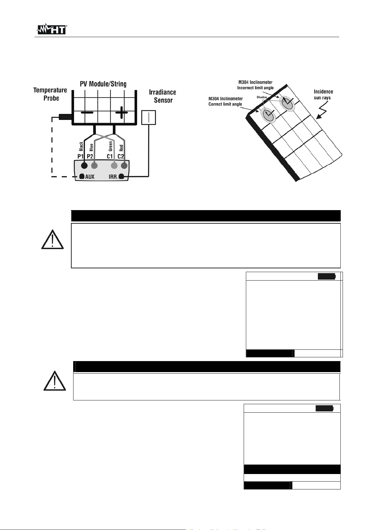
I-V400 - SOLAR I-V
19. Connect the meter to the module/string under test as shown in Fig. 7a. In particular,
connect the negative output pole of module/string to P1, C1 input terminals and the
positive output pole of module/string to P2, C2 input terminals
Fig. 7a: Instrument connection to module/string FV Fig. 7b: Positioning of inclinometer M304
CAUTION
The method used by the instrument meter for output VDC and IDC
measurements of PV module/string is the “4-wire”. Therefore, it is possible to
use also test cables connected to P1, C1, P2, C2 inputs of different length
without performing any calibration of cable resistance. It is recommended to
use cables with a § 4mm2
20. After connection to the plant, the real time values of
15/05/10 15:34:26
parameters are shown by meter:
Vdc = DC output voltage of PV module/string
Irr = Irradiance value measured by sensor
Tc = Value of module temperature
CAUTION
Vdc = 367 V
Irr = 1045 W/m2
Tc = 45 °C
Module: SUNPOWER 210
Select
I - V
At the press of GO/STOP key some different error messages can be
displayed by the meter (see § 6.4) and, due of this, the test cannot start.
21. Press GO/STOP key to start the test. If none of the
previous error messages are detected, the message
Check and remove, if possible, this error message before start the test
15/05/10 15:34:26
Vdc = 367 V
“Measuring…” is shown on the display for some seconds,
depending on the level of power during test.
Irr = 1045 W/m2
Tc = 45 °C
Module: SUNPOWER 210
Measuring…
Select
I - V
EN - 35
Page 38

I-V400 - SOLAR I-V
22. At the end of test, the values of typical parameters (all
referred to a single module in standard conditions STC)
are shown by the meter together with the final response (§
6.2.3) based on the automatic calculation performed and
relevant to:
Translation of I-V curve to STC condition
Verification of tolerance % of the maximum power
declared by the manufacturer.
CAUTION
The instrument refer all the values of parameters to one only module at
the STC condition
The total voltage of the string, obtained at OPC, is divided for the number
of module of it. Considering this “average” value, together with the
measured current, the instrument perform the I-V curve @ OPC
calculation which is the translated at the STC condition
23. Press ENTER for the display of measurement results both
in numeric and graphical mode referred to STC or OPC
conditions (see § 6.2.3).
24. Use the arrow key for the selection of table or graph
visualization.
25. Press SAVE key to store the result of test (see § 7.2) or
ESC/MENU key to exit without saving and to go back to
the main menu.
15/05/10 15:34:26
Voc = 15.2 V
Vmpp = 14.7 V
Impp = 4.7 A
Isc = 5.2 A
Pmax = 200 W
FF = 77.1 %
DPmax = 2.1 %
Results @ STC – Response: OK
Select
15/05/10 15:34:26
Voc = 15.2 V
Vmpp = 14.7 V
Impp = 4.7 A
Isc = 5.2 A
Pmax = 200 W
FF = 77.1 %
DPmax = 2.1 %
Table
Graph
Select
I - V
– Response: OK
I - V
EN - 36
Page 39

I-V400 - SOLAR I-V
6.2.2. I-V curve measurement by use of remote unit SOLAR-02
The I-V curve test with Irr/Temp measurement by use of remote unit SOLAR-02 can be
performed in one of the herewith mode:
Remote unit SOLAR-02 in RF connection with main unit
Remote unit SOLAR-02 in synchro recording (no RF connection with main unit)
6.2.2.1. I-V curve test by remote unit SOLAR-02 in RF connection
This mode is possible ONLY if the distance between the main unit and the remote unit
SOLAR-02 can establish always a stable RF connection. This distance limit is influenced
by obstacles, air humidity, etc., so it is considered valid about some meters.
CAUTION
The maximum voltage among P1, P2, C1, and C2 inputs is 1000V DC. Do
not measure voltages exceeding the limits prescribed by this manual
The maximum current measured by the meter is 10A. Do not perform test
on strings of PV modules in parallel with them
Do not perform test on PV modules or strings connected to DC/AC
converter
1. Turn on the meter by pressing ON/OFF key
2. Check that option YES relative to the selection of remote unit SOLAR-02 should be set
on the instrument (see § 5.1.4)
3. Check that the values set on the “Remote unit” section (see § 5.1.4) should be
consistent with the reference cell depending on the kind of module/string on test
4. Check that the value set on “Irradiance” section (see § 5.1.5) should be consistent with
the measurement to perform. It is suggested to perform the measurement with a
threshold 700 W/m2 in compliance to the IEC/EN60891 guideline
5. Back to the main menu and select the “I-V” option
6. Press ENTER, by means of arrow keys (,) select
item “Meas. Type ”
15/05/10 15:34:26
Vdc = 0.0 V
7. Using the key, select item “I-V Test” and confirm by
pressing ENTER
Irr = 0 W/m2
Tc =- - - °C
Modulo: SUNPOWER 210
I-V Test
Set RS Test
Mea IV Fast Check
Select
I - V
8. Switch on the remote unit SOLAR-02 and wait that “Radio connection active”
message is displayed
EN - 37
Page 40

I-V400 - SOLAR I-V
9. The instrument displays a screen similar to the one
reported here to the side, where:
Vdc = DC output voltage from module/string
Irr = irradiance measured by supplied reference cell
Tc = temperature of module. The herewith options are
available for this field:
AUTO automatic mode of temperature
measurement
Number MAN or AUX mode of temp.
measurement
“ - - - “ AUX mode with no connected probe
Module = type of selected module
Temp = measurement mode of module temperature
The symbol “ ” fixed at display means that a stable
RF connection is established with the remote unit
SOLAR-02
10. Press ENTER key, select the “ Settings” item and confirm
again with ENTER to access the next screen which allows
setting the type of PV module and the number of modules
relative to the PV string under test.
15/05/10 15:34:26
Vdc = 0.0 V
Irr = - - - W/m2
Tc = Auto °C
Module: PANEL01
Temp: Auto
Select
15/05/10 15:34:26
I – V
Vdc = 0.0 V
Irr = - - - W/m2
11. By means of arrow keys (,) select the type of PV
module included in the database of meter (§ 5.3.1)
12. By means of arrow keys (,) select the item “N. of
Mod.” and by means of arrow keys (,) set the number
of modules of the PV string under test. The maximum
number of modules is 50
13. By means of arrow keys (,) select the “Rs” item and
by means of arrow keys (,) choose the “Manual” or
“Auto” mode for the serial resistance measurement (§
6.2.4)
14. By means of arrow keys (,) select the type of PV
module included in the database of meter (§ 5.3.1). By
means of arrow keys (,) select the “Temp” item and
by means of arrow keys (,) choose the type of module
temperature among the modes listed:
Auto” automatic measurement performed by the
meter depending on the measured value of open
voltage of modules (recommended method)
“Manual” setting of a module temperature value by
the operator on the corresponding “Value” field
“Aux” setting of temperature of module performed by
auxiliary probe
15. Confirm with SAVE key or press ESC/MENU key to exit
without saving
Tc = - - - °C
Module: PANEL01
Settings
Meas. Type
Select
15/05/10 15:34:26
Type : SUNPOWER 210
N.of Mod. : 15
Rs : Auto
Temp : Manual
Value : 51°C
Pmax = 210
Voc = 47.70
Vmpp = 40.00
Isc = 5.75
Impp = 5.25
I - V
SET
EN - 38
Page 41
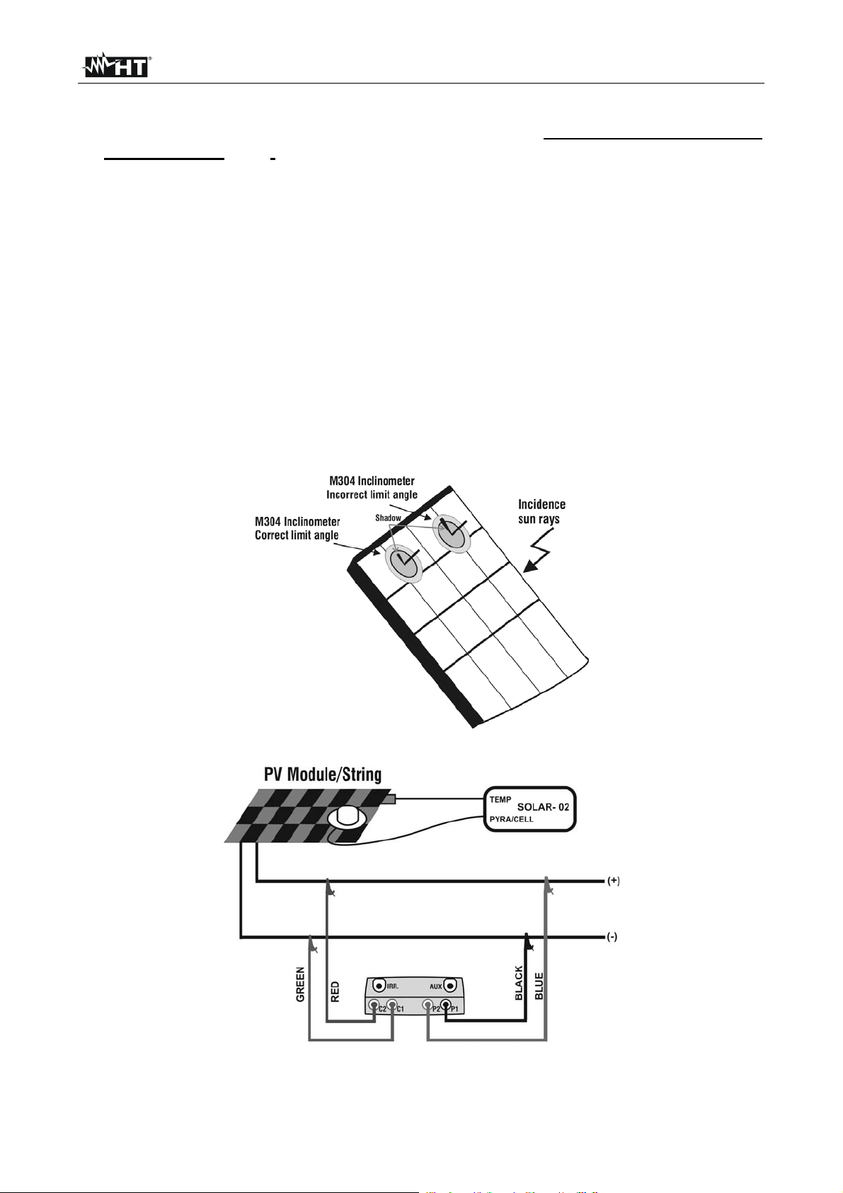
I-V400 - SOLAR I-V
16. Mount the M304 (inclinometer) supplied accessory, place and hold it on the plane of module.
Verify that the sun shadow falls on the disc within the “limit internal circle” on the
disc itself (see Fig . 8 ). If this is not the case, the incidence angle between sun rays
and the module surface is too high and not complying with the test conditions
declared by the module manufacturer. As a consequence the measurements
performed by the meter are not ok and all measurements steps shall be repeated at
another daytime
17. Fix the support of the cell to the module by using the supplied set of screws and mount the
reference cell on it possibly with output terminals downwards with respect to the
module. Rotate the cell upwards to lean it on the small wing of the support so as the cell is
perfectly parallel to the plane of module, then fix it with the relevant screws supplied
18. Connect the output of re ference cell (depending on the type of module under test) at
the PYRA/CELL input of remote unit SOLAR-02 by using the supplied cable
19. Connect, if used, the auxiliary temperature probe to the TEMP input of remote unit
SOLAR-02 and on the rear of module, fixing it with adhesive tape
20. Connect the meter to the module/string under test as shown in Fig.9. In particular,
connect the negative output pole of module/string to P1, C1 input terminals and the
positive output pole of module/string to P2, C2 input terminals
Fig. 8: Positioning the M304 inclinometer
Fig. 9: Connection of units to the PV module/string
EN - 39
Page 42

I-V400 - SOLAR I-V
21. The instrument displays a screen similar to the one
reported here to the side, where:
Vdc = DC output voltage from module/string.
Irr = irradiance measured by supplied reference cell
Tc = temperature of module. The herewith options are
available for this field:
AUTO automatic mode of temperature measurement
Number MAN or AUX mode of temp. measurement
“ - - - “ AUX mode with no connected probe
Module = type of selected module
Temp = measurement mode of module temperature
The symbol “ ” fixed at display means that a stable
RF connection is established with the remote unit
SOLAR-02
CAUTION
At the press of GO/STOP key some different error messages can be
displayed by the meter (see § 6.3) and, due of this, the test cannot start.
Check and remove, if possible, this error message before start the test
22. Press GO/STOP key to start the test. If none of the
previous error messages are detected, the message
“Measuring…” is shown on the display for some seconds,
depending on the level of power during test.
23. At the end of test, the values of typical parameters (all
referred to a single module in standard conditions STC)
are shown by the meter together with the final response (§
6.2.3) based on the automatic calculation performed and
relevant to:
Translation of I-V curve to STC condition
Verification of tolerance % of the maximum power
declared by the manufacturer.
24. Press ENTER for the visualization of measurement results
referred at STC or OPC conditions both in numeric and
graphical mode (§ 6.2.3)
25. Use the arrow key for the selection of table or graph
visualization
26. Press SAVE key to store the result of test (see § 7.2) or
ESC/MENU key to exit without saving and to go back to
the main menu.
15/05/10 15:34:26
Vdc = 367 V
Irr = 1045 W/m2
Tc = 45 °C
Module: SUNPOWER 210
Select
15/05/10 15:34:26
I – V
Vdc = 367 V
Irr = 1045 W/m2
Tc = 45 °C
Module: SUNPOWER 210
Measuring…
Select
15/05/10 15:34:26
Voc = 15.2 V
Vmpp = 14.7 V
Impp = 4.7 A
Isc = 5.2 A
Pmax = 200 W
FF = 77.1 %
DPmax = 2.1 %
Results @ STC – Response: OK
Select
15/05/10 15:34:26
Voc = 15.2 V
Vmpp = 14.7 V
Impp = 4.7 A
Isc = 5.2 A
Pmax = 200 W
FF = 77.1 %
DPmax = 2.1 %
Table
Graph
Select
I - V
I - V
– Response: OK
I - V
EN - 40
Page 43

I-V400 - SOLAR I-V
6.2.2.2. I-V curve test by remote unit SOLAR-02 in synchro recording
This mode, which consists in an independent recording of the irradiance and temperature
parameters by the remote unit SOLAR-02, permits to perform I-V curve test also with wide
distance between the instrument and SOLAR-02 without any connection between them.
On the other hand, due to the impossibility for the meter to have immediately the values of
irradiance/temperature, it is necessary wait the transfer of data from remote unit SOLAR02 to main unit in order to have all the available results.
CAUTION
The maximum voltage among P1, P2, C1, and C2 inputs is 1000V DC. Do
not measure voltages exceeding the limits prescribed by this manual
The maximum current measured by the meter is 10A. Do not perform test
on strings of PV modules in parallel with them
Do not perform test on PV modules or strings connected to DC/AC
converter
1. Turn on the meter by pressing ON/OFF key
2. Check that option YES relative to the selection of remote unit SOLAR-02 should be set
on the instrument (see § 5.1.4)
3. Check that the value set on “Irradiance” section (see § 5.1.5) should be consistent with
the measurement to perform. It is suggested to perform the measurement with a
threshold 700 W/m2 in compliance to the IEC/EN60891 guideline
4. Back to the main menu and select the “I-V” measurement mode
5. Press ENTER, by means of arrow keys (,) select
item “Meas. Type ”
15/05/10 15:34:26
Vdc = 0.0 V
6. Using the key, select item “I-V Test” and confirm by
pressing ENTER
Irr = 0 W/m2
Tc =- - - °C
Module: SUNPOWER 210
I-V Test
Set RS Test
Mea IV Fast Check
Select
I - V
7. Switch on the remote unit SOLAR-02 and wait that “Radio connection active” message
is displayed
8. Check the status of internal batteries of SOLAR-02 (the “
” symbol should be not
displayed)
9. Check that the values of sensitivity and temperature coefficient set on the SOLAR-02
section should be consistent with the reference cell depending on the kind of
module/string on test (see user manual of SOLAR-02)
EN - 41
Page 44

I-V400 - SOLAR I-V
10. The instrument displays a screen similar to the one
reported here to the side, where:
Vdc = DC output voltage from module/string
Irr = irradiance measured by supplied reference cell
Tc = temperature of module. The herewith options are
available for this field:
AUTO automatic mode of temperature measurement
Number MAN or AUX mode of temp. measurement
“ - - - “ AUX mode with no connected probe
Module = type of selected module
Temp = measurement mode of module temperature
The symbol “ ” fixed at display means that a stable
RF connection is established with the remote unit
SOLAR-02
11. Press ENTER key, select the “Settings” item and confirm
again with ENTER to access the next screen which allows
setting the type of PV module and the number of modules
relative to the PV string under test.
15/05/10 15:34:26
Vdc = 0.0 V
Irr = - - - W/m2
Tc = Auto °C
Module: PANEL01
Temp: Auto
Select
15/05/10 15:34:26
I – V
Vdc = 0.0 V
Irr = - - - W/m2
12. By means of arrow keys (,) select the type of PV
module included in the database of meter (§ 5.3.1)
13. By means of arrow keys (,) select the item “N. of
Mod.” and by means of arrow keys (,) set the number
of modules of the PV string under test. The maximum
number of modules is 50
14. By means of arrow keys (,) select the “Rs” item and
by means of arrow keys (,) choose the “Manual” or
“Auto” mode for the serial resistance measurement (§
6.2.4)
15. By means of arrow keys (,) select the type of PV
module included in the database of meter (§ 5.3.1). By
means of arrow keys (,) select the “Temp” item and
by means of arrow keys (,) choose the type of module
temperature among the modes listed:
Auto” automatic measurement performed by the
meter depending on the measured value of open
voltage of modules (recommended method)
“Manual” setting of a module temperature value by
the operator on the corresponding “Value” field
“Aux” setting of temperature of module performed by
auxiliary probe
16. Confirm with SAVE key or press ESC/MENU key to exit
without saving
Tc = - - - °C
Module: PANEL01
Settings
Meas. Type
Select
15/05/10 15:34:26
Type : SUNPOWER 210
N.of Mod. : 15
Rs : Auto
Temp : Manual
Value : 51°C
Pmax = 210
Voc = 47.70
Vmpp = 40.00
Isc = 5.75
Impp = 5.25
I - V
SET
EN - 42
Page 45
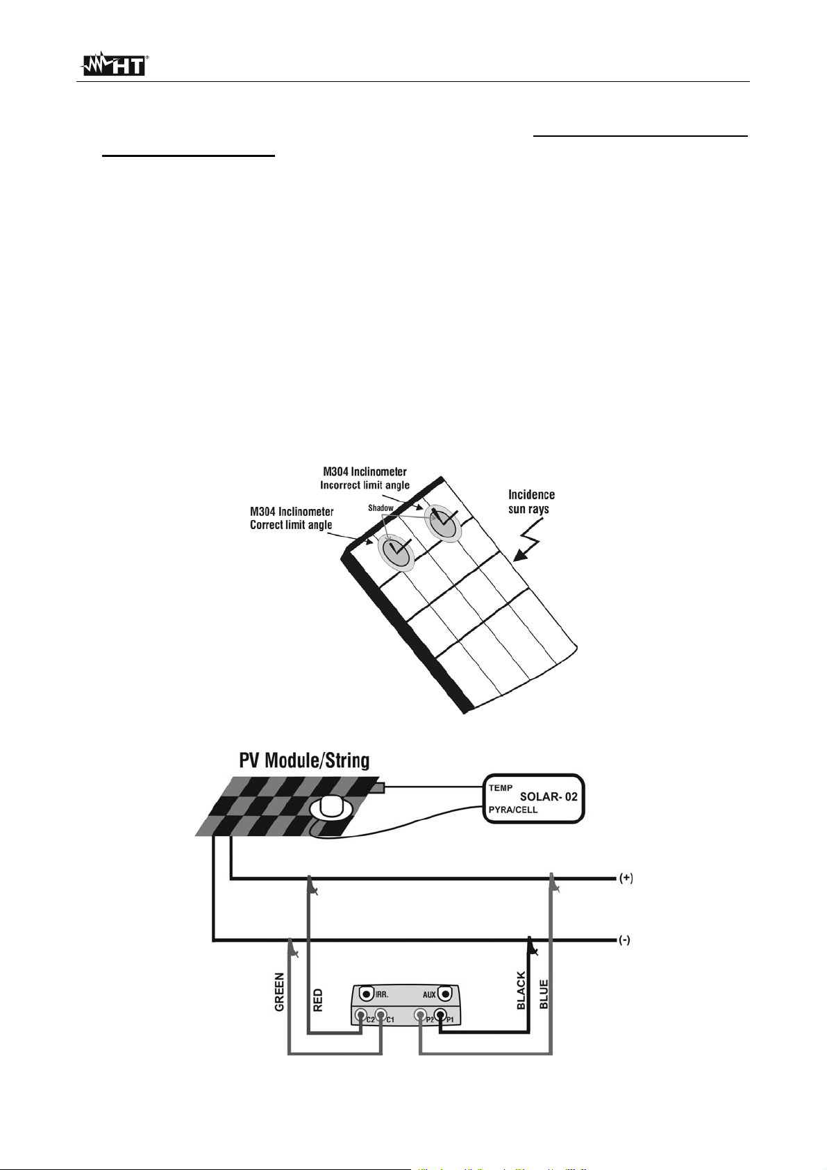
I-V400 - SOLAR I-V
17. Mount the M304 (inclinometer) supplied accessory, place and hold it on the plane of module.
Verify that the sun shadow falls on the disc within the “limit internal circle” on the
disc itself (see Fig. 10). If this is not the case, the incidence angle between sun rays
and the module surface is too high and not complying with the test conditions
declared by the module manufacturer. As a consequence the measurements
performed by the meter are not ok and all measurements steps shall be repeated at
another daytime
18. Fix the support of the cell to the module by using the supplied set of screws and mount the
reference cell on it possibly with output terminals downwards with respect to the
module. Rotate the cell upwards to lean it on the small wing of the support so as the cell is
perfectly parallel to the plane of module, then fix it with the relevant screws supplied
19. Connect the output of reference cell (depending on the type of module under test) at
the PYRA/CELL input of remote unit SOLAR-02 by using the supplied cable
20. Connect, if used, the auxiliary temperature probe to the TEMP input of remote unit
SOLAR-02 and on the rear of module, fixing it with adhesive tape
21. Connect the meter to the module/string under test as shown in Fig.11. In particular,
connect the negative output pole of module/string to P1, C1 input terminals and the
positive output pole of module/string to P2, C2 input terminals
Fig. 10: Positioning the M304 inclinometer
Fig.11: Connection of units to the PV module/string
EN - 43
Page 46
I-V400 - SOLAR I-V
22. The instrument displays a screen similar to the one
reported here to the side, where:
Vdc = DC output voltage from module/string
Irr = irradiance measured by supplied reference cell
Tc = temperature of module. The herewith options are
available for this field:
AUTO automatic mode of temperature measurement
Number MAN or AUX mode of temp. measurement
“ - - - “ AUX mode with no connected probe
Module = type of selected module
Temp = measurement mode of module temperature
The symbol “ ” fixed at display means that a stable
RF connection is established with the remote unit
SOLAR-02
23. Press ENTER key, select the “Activate Rec.” item and
confirm with ENTER. The message “Remote unit in
recording…” is displayed on the meter. In this condition is
possible to start the I-V curve tests always considering
that the complete results will be available only after the
stop of recording of SOLAR-02 and transfer them from the
same remote unit
CAUTION
At the press of GO/STOP key some different error messages can be
displayed by the meter (see § 6.4) and, due of this, the test cannot start.
Check and remove, if possible, this error message before start the test
24. Press GO/STOP key to start the test. If none of the
previous error messages are detected, the message
“Measuring…” is shown on the display for some seconds,
depending on the level of power during test.
15/05/10 15:34:26
Vdc = 367 V
Irr = 1045 W/m2
Tc = 45 °C
Module: SUNPOWER 210
Select
15/05/10 15:34:26
I – V
Vdc = 0.0 V
Irr = - - - W/m2
Tc = - - - °C
Activate Rec.
Settings
Meas. Type
Select
15/05/10 15:34:26
I – V
Vdc = 367 V
Irr = - - - W/m2
Tc = Auto °C
Module: SUNPOWER 210
Measuring…
Select
I - V
EN - 44
Page 47
I-V400 - SOLAR I-V
2
2
25. At the end of test, based on the descriptions of previous
points, the message “STC Data available after Stop rec” is
displayed and then the results at OPC conditions are
displayed
15/05/10 15:34:26
Voc = 15.2 V
Vmpp = 14.7 V
Impp = 4.7 A
Isc = 5.2 A
Pmax = 200 W
FF = 77.1 %
Irr = - - - W/m
Tc = Auto
Results @ OPC
Select
I - V
26. Press ENTER for the visualization of measurement results
both in numeric and graphical mode (§ 6.2.3)
27. Use the arrow key for the selection of table or graph
visualization
28. Press SAVE key to store the result of test or ESC/MENU
key to exit without saving and to go back to the main
screen
15/05/10 15:34:26
Voc = 15.2 V
Vmpp = 14.7 V
Impp = 4.7 A
Isc = 5.2 A
Pmax = 200 W
FF = 77.1 %
Irr = --- W/m
Table
Graph
Select
I - V
29. At the end of I-V test, press the ENTER key, select the
“Stop recording” item and confirm with ENTER. The
messages “Wait…” and then “STC Data available in MEM”
are displayed
30. In this conditions, for the I-V tests performed with
irradiance values over the limit threshold and stable, the
correspondent STC results will be available inside memory
15/05/10 15:34:26
Vdc = 0.0 V
Irr = - - - W/m2
Tc = Auto °C
Stop Reg.
Settings
Meas. Type
Select
I - V
31. The message “Download data” is displayed on the instrument and, at the same time,
the message “Send” is displayed on SOLAR-02 which means the transfer of irradiance
values and, if necessary, the module temperature values on the main unit
32. At the end of data transfer the instrument automatically join the average value of
irradiance (detected with IP = 5s) to each I-V test performed and, correspondingly, will
calculate the results translated to STC conditions and the Yes/No response for each
test. The complete results are recalled at display as described in § 7.3.2. See the §
6.2.3 for the meaning of measurement results
EN - 45
Page 48

I-V400 - SOLAR I-V
6.2.3. Meaning of measurement results
The parameter measured and calculated by meter have the following meaning:
Parameter Description
Pmax Maximum power of module measured by the meter
DPmax Difference % of maximum measured power from nominal power (@ STC)
FF Fill Factor %
Voc Open voltage
Vmpp Voltage on point of maximum power
Isc Short circuit current
Impp Current on point of maximum power
Table 2: List of parameter measured by the meter
Where:
DPmax = 100 ABS [(Pmax – Pnom) / Pnom] check parameter which defines the final
response of test
Pnom = nominal power of module
FF = 100 x [(Vmpp x Impp ) / (Voc x Isc)] = Fill Factor represents a kind of “efficiency” of
module/string as it is a ratio between the maximum power measured and the open power
The meter gives the following final response:
Response Condition Note
OK
- Tol
(-)
+
Meter
Meas
Tol
(+)
-
Meter
(1)
The previous relation (1) is not verified but the following is valid:
OK*
- Tol
(-)
Meas
Tol
(+)
(2)
The relations (1) and (2) are not verified but the following is valid:
NO OK*
NO OK
where:
(-)
Tol
(+)
Tol
Meas
and declared values
Meter
(-)
= Tol
= Tol
(%)*Pnom Negative tolerance in absolute value, declared by manufacturer
(+)
(%)*Pnom Positive tolerance in absolute value, declared by manufacturer
= Pmax – Pnom DPmax which defines the difference between measured values
Absolute error of the measurement chain (meter + transducers in the point of
measure) considering the error % and the declared dgt
None of the relations (1), (2) and (3) are verified (4)
- Tol
(-)
-
Meter
Meas
Tol
(+)
+
Meter
(3)
(1) OK Positive response of test also considering the error of measurement chain
(2) OK* Response of test positive less than the error of measurement chain
(3) NO OK* Response of test negative less than the error of measurement chain
(4) NO OK Negative response of test also considering the error of measurement chain
EN - 46
Page 49

I-V400 - SOLAR I-V
6.2.4. Serial resistance Rs
The serial resistance Rs is one of the typical elements of PV modules which can affect the
I-V curve measurement of the panels themselves. The instrument meter performs the Rs
calculation, during the measurement of I-V curve (§ 6.2.1), in the following modes:
AUTOMATIC mode the Rs calculation is automatically performed by meter using an
approximate evaluation based on the measurement of I-V curve.
MANUAL mode the Rs value is given by the internal database where it can be
manually input by the operator (§ 5.3.1) or measured (§ 6.2.4.1).
6.2.4.1. Serial resistance Rs measurement
The reference standard IEC/EN60891 defines the Rs value with 2 different consecutive
measurements at the following conditions:
Measurement #1: irradiance > 500 W/m2
Measurement #2: irradiance less respect to the previous measurement #1
CAUTION
The maximum voltage among P1, P2, C1, and C2 inputs is 1000V DC. Do
not measure voltages exceeding the limits prescribed by this manual.
Should you exceed the voltage limits you could damage the instrument
and/or its components or endanger your safety.
1. Turn on the meter by pressing ON/OFF key.
2. Check the specifications of the reference cell (parameters Alpha and Sens.) on meter
depending on the type of module MONOcrystal or MULTIcrystal under test (§ 5.1.4)
3. Check the minimum irradiance threshold set on meter (§ 5.1.5). It is recommended to
perform measurements with threshold 700 W/m2 in compliance with IEC/EN60891
standard
4. Press ESC/MENU key to enter to the herewith main menu
5. Select the “I-V” item and press ENTER to access the I-V curve measurement §
6. Press the ENTER key, select the “Settings” item and
confirm again with ENTER. Select the type of PV module
15/05/10 15:34:26
Vdc = 0.0 V
under test among the available models as described in §
5.3.1.
Irr = - - - W/m2
Tc = - - - °C
Module: PANEL01
Settings
Meas. Type
Select
7. Note the name of the selected module (ex: SUNPOWER 210) in the screen
EN - 47
I - V
Page 50

I-V400 - SOLAR I-V
8. Press ENTER key and by means of arrow keys (,)
select the item “Meas. Type ”
9. By means of arrow key access the internal submenu,
select the item “RS Test” and confirm with ENTER to
open the main screen of Rs measurement.
10. The herewith screen is shown on the display, where:
Rs = serial resistance
Vdc = DC output voltage from module
Irr = irradiance measured by supplied reference cell
Module = active module
15/05/10 15:34:26
Vdc = 0.0 V
Irr = 0 W/m2
Tc =- - - °C
Module: SUNPOWER 210
Set RS Test
Mea I-V Test
Select
15/05/10 15:34:26
Rs
Vdc
Irr
= - - -
= 0.0 V
= 0 W/m2
I - V
Module: SUNPOWER 210
Select
RS Mode
11. Mount the M304 (inclinometer) supplied accessory, position and hold it on the plane of
module. Verify that the sun shadow falls on the disc w ithin the “limit internal circle”
on the disc itself (Fig.12b). If this is not the case the incidence angle between sun
rays and the module surface is too high and not complying with the test conditions
declared by the module manufacturer. As a consequence the measurements
performed by the meter are not ok and all measurements steps shall be repeated at
another daytime.
12. Connect the MONO or MULTI output (depending on the type of module under test) of
reference cell at the IRR. input of meter by using the cable supplied with the cell.
13. Fix the support of the cell to the module by using the supplied set of screws and mount
the reference cell on it possibly with output terminals downwards with respect to
the module. Rotate the cell upwards to lean it on the small wing of the support to have
it perfectly parallel to the module plane, then fix it with the relevant screws supplied.
14. Connect the meter to the module/string under test as shown in Fig.12a In particular,
connect the negative output pole of module/string to P1, C1 input terminals and the
positive output pole of module/string to P2, C2 input terminals
Fig. 12a: Instrument connection to module FV Fig. 12b: Positioning inclinometer M304
EN - 48
Page 51

I-V400 - SOLAR I-V
15. After connection to the panel, the real time values are
shown by meter:
Open voltage of module installation
Irradiance value on the panel installation, measured by
reference cell
15/05/10 15:34:26
Rs
Vdc
Irr
= - - -
= 367 V
= 1045 W/m2
Module: SUNPOWER 210
CAUTION
Select
RS Mode
After pressing the GO/STOP key, some different messages can be shown by
the meter (§ 6.3) and, in this case, the meter does not perform the test.
Check and, if possible, solve this situation before carrying on with the test.
16. Press GO/STOP key to start the test. If none of the
previous error messages are detected, the message
“Measuring 1 running…” is displayed for about 5 s and
the meter performs the first measurement of Rs with the
standard conditions of module irradiance (§ 5.1.5).
17. After performing the first measurement, the meter enters a
waiting mode before starting the second measurement,
which should be performed with the panel partially
obscured and the message “Wait for modifying Irrad.”
18. Cover the module under test and the reference cell (e.g.
15/05/10 15:34:26
Rs
Vdc
Irr
Module: SUNPOWER 210
Select
15/05/10 15:34:26
Rs
Vdc
Irr
= - - -
= 367 V
= 1045 W/m2
Measure 1 running…
RS Mode
= - - -
= 367 V
= 1045 W/m2
by using a white plexiglass sheet) in order to reduce the
irradiance value measured by a percentage ranging from
40% up to 70% with respect to the previous test.
CAUTION
Module: SUNPOWER 210
Select
Wait for modify Irrad.
RS Mode
Do not modify the inclination of the module during the obscuring operation
to avoid possible errors on measurements
After pressing the GO/STOP key, some different messages can be shown
by the meter (§ 6.4) and, in this case, the meter does not perform the test.
Check and, if possible, solve this situation before carrying on with the test
19. Press GO/STOP key to start the second measurement. If none of the previous error
messages are detected, the meter gives the definitive value of Rs parameter for the
panel under test as combination of two previous measurements
20. Press SAVE key to save the result and the “Saved data” message is displayed for a
while. Press ESC/MENU key to exit without saving and to go back to the previous
screen.
EN - 49
Page 52

I-V400 - SOLAR I-V
6.3. QUICK CHECK ON PV MODULES AND STRINGS (IVCK)
6.3.1. General information
This function permits to carry out a quick Test of a panel/string just measuring open circuit
voltage and short circuit current in compliance with IEC/EN62446. Consequently both
irradiance and temperature module values can be measured (using corresponding probes).
Irradiation measurement can be executed only adopting one of the following modes:
Irradiance sensor directly connected to I-V400 or SOLAR I-V
Irradiance sensor connected to SOLAR-02 through RF to I-V400 or SOLAR I-V
Irradiance measurements are always effected in real time, it is impossible to start a “remote”
recording of irradiance values through SOLAR-02
If minimum IV irradiance threshold is set (see § 5.1.5):
= 0 the instrument does not control the presence of cell, irradiance changes, number of
modules and does not display error messages should it be impossible to calculate Voc
and Isc values transposed to Voc and Isc under STC. This mode is suitable to effect a
test session on a considerable number of strings as quickly as possible.
> 0 (suggested > 700) the instrument carries out all tests provided for I-V, manages all
conditions and error messages for I-V test (wrong num. Mod., Temp. out of range, cell
presence, Min Irr, etc..) and calculates values of Voc and Isc under STC. This mode is
recommended whenever thorough tests are to be effected on modules/strings under test.
In general the result page will include:
Description of the module
Irradiance and temperature values (if available)
Average values of Voc and Isc calculated as average of the corresponding values under
OPC on the last 10 tests saved into memory. If the number of tests is < 10 the average is
calculated on the number of available tests. The first test will display dashes in the field
“average values” as there are no previous tests on which average can be calculated.
The values of Voc and Isc measured under OPC as well as any partial outcome (the latter
available only if STC values are not available) obtained through comparison with average
values.
The values of Voc and Isc calculated under STC (if available) and any partial outcome
obtained comparing the values calculated under STC with the nominal ones (inserted in
DB modules).
The overall test outcome (OK(NO). The overall result will be calculated based on the
partial results.
Based on partial outcome under STC (if these are available)
Based on partial outcome under OPC (if STC values are not available)
The instrument will not display any overall outcome if no partial result is available.
In case of negative outcome it is advisable to effect measurement of I-V feature (see § 6.2) in
order to thoroughly analysis of the module/string under test.
EN - 50
Page 53

I-V400 - SOLAR I-V
6
3
A
646
A
Avg
S
A
1°C
(
)
(
)
6.3.2. Preliminary settings
1. Turn the instrument on by pressing ON/OFF key.
2. Press ESC/MENU to display the main menu.
3. Select “I-V” and press ENTER to enter the FV module performance measurement section.
In general when selecting I-V from main menu the instrument shows automatically the
last mode under use (I-V or IVCK).
4. In case the current mode is not IVCK, press ENTER,
select “Measurement ” by means of arrow keys
15/05/10 15:34:26
Vdc = 0.0 V
(,).Use the arrow key to enter the internal
submenu, select “IV Check” and confirm by ENTER to
start up the initial screen of rapid test IVCK.
Irr = 0 W/m2
Tc =- - - °C
Module: SUNPOWER 210
I-V Test
Set Rs Test
Mea I-V Fast Check
5. Press ENTER, select “Settings” and confirm by
pressing ENTER again to enter the following screen
where it is possible to set module type and number of
modules making the string under test.
6. Use the arrow keys ( , ) to select the module type
among the ones stored inside the instrument’s database
(see § 5.3.1)
7. Use the arrow keys (,), select “Mod. per Str” and
use the arrow keys ( , ) to enter the number of
modules for the string under test. The maximum number
of modules to be set is 50
8. Use the arrow keys (,), select “Temp” and use the
arrow keys ( , ) to select the measurement type of
the module temperature among the modes:
Select
15/05/10 15:34:26
Module: SUNPWR210
Irr 980W/m2
Tc (AUTO) 49°C
VocMed@OPC
IscMed@OPC 5.4
Voc@OPC
Isc@OPC ---
Reset V
ettings
Meas Type
Select
15/05/10 15:34:26
Tipo : SUNPOWER 210
Mod. x Str : 15
Rs : Auto
Temp : Manual
Value : 5
Tol Voc : 3%
Tol Isc : 3%
Voc = 64.7 %
Isc = 6.20 %
I - V
IVCK
SETTING
47V
V
+4%
+4%
“Auto” automatic measurement carried out according to the measured open circuit
voltage value of modules (recommended method)
Manual entering the known value for the module temperature in the corresponding
field “Value”
Aux temperature measurement with probe
Note: Settings for parameter “Rs” are ignored for measurements type IVCK.
9. Use the arrow keys (,), select “Tol Voc” and “Tol Isc” then use the arrow keys ( , )
to set the tolerance values for open circuit voltage (Voc) and short circuit current (Isc)
provided by the module manufacturer (values allowed: +0% .. +25%). Please note that the
instrument’s uncertainty is indicated in brackets beside the above mentioned values and it
will be added to the value entered to get the outcome (OK/NO).
10. Press SAVE to store the measurements effected or ESC/MENU to quit without saving.
EN - 51
Page 54
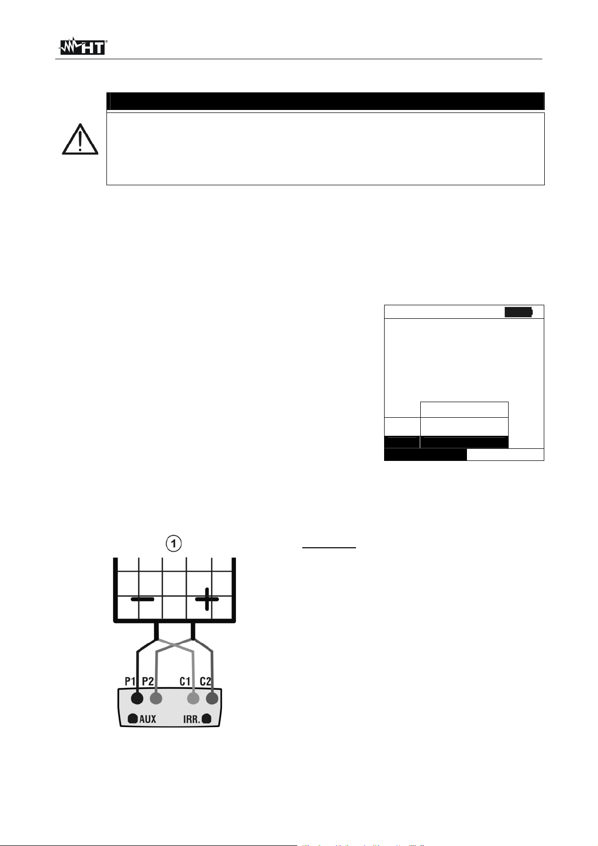
I-V400 - SOLAR I-V
6.3.3. Fast check IVCK without irradiance measurement
CAUTION
The maximum voltage among inputs P1, P2, C1 and C2 is 1000V DC. Do not
measure voltages exceeding the limits expressed in this manual.
The maximum current allowable for the instrument is 10A. Do not effect tests
in parallel on FV module strings.
Never effect tests on modules or FV strings connected to DC/AC converter.
1. Turn on the instrument pressing ON/OFF
2. Check that remote unit SOLAR-02 is not selected (see § 5.1.4– setting NO)
3. Check that the value of minimum irradiance set in the section “Irradiance” (see §5.1.5)
is equal to 0
4. Go back to main MENU and select “I-V”
5. Select “I-V” and press ENTER to enter the section of FV module performance
measurement. Generally when selecting I-V on general menu the instrument automatically
shows the last mode under use (I-V or IVCK).
6. In case the current mode is not IVCK, press ENTER,
select “Measurement ” by means of arrow keys
15/05/10 15:34:26
Vdc = 0.0 V
(,). Use the arrow key to enter the internal
submenu, select “IV Check” and confirm pressing
ENTER to start up the initial screen of fast check IVCK.
Irr = 0 W/m2
Tc =- - - °C
Module: SUNPOWER 210
Feature IV
Imp
Mis IV Check
Selection
Measuremen
t RS
I - V
7. Check the preliminary settings based on descriptions of § 6.3.2
8. Connect the instrument to the module/string under test as shown in the following
picture. In particular connect the negative pole of the module/string to terminals P1, C1
and it positive pole to terminals P2, C2.
CAPTION:
P1: Black cable
P2: Blue cable
C1: Green cable
C2: Red cable
1: Module or FV string
Fig. 10: Connection to module/FV string for IVCK tests without irradiance measurement
EN - 52
Page 55

I-V400 - SOLAR I-V
A
A
A
°C
6
3
A
6
3
A
A
9. The initial screen under IVCK mode displays the values
of:
Module under use
The average values of Voc and Isc under OPC conditions.
The value of Voc measured under OPC conditions
CAUTION
When pressing the GO/STOP key the instrument can provide different error
messages (see §6.3) and, as direct consequence, not carry out the test. Check
and eliminate, if possible, causes of the problems before continuing the test.
10. Press GO/STOP to start the test. In case of no error
conditions, the instrument displays the screen with results
as shown sideways. It displays as follows:
The module under use
The average values of Voc and Isc under OPC conditions
The values of Voc and Isc measured under OPC and
relative partial outcome resulting after comparing the
average values. In general:
15/05/10 15:34:26
Module: SUNPWR210
Irr. ---W/m2
Tc (AUTO) ---°C
VocMed@OPC 647V
IscMed@OPC 5.43
Voc@OPC 646V
Isc@OPC --Voc@STC ---V
Isc@STC ---
Selection
IVCK
15/05/10 15:34:26
Module: SUNPWR210
Irr ---W/m2
Tc (AUTO) --
VocMed@OPC
IscMed@OPC 5.4
Voc@OPC
Isc@OPC 5.
Voc@STC ---V
Isc@STC ---
OUTCOME: OK
Selection
IVCK
47V
47VOK
5
OK
VocVocAvg
@@
OPC
OPCOPC
@@
OPCOPC
OPC
OPC
OKVocO
OKIscO
@
@
VocAvg
@
IscIsAvg
IscAvg
@
OPC
4% Voc Tol100 if utcome
4% Isc Tol100 if utcome
The overall value of outcome:
o OK: if all results under OPC are OK,
o NO if one of the results under OPC is NO
11. Press SAVE to store the test result into the instrument’s memory (see §7.2) or press
ESC/MENU to quit without saving and go back to main measurement screen.
NOTES on displayed AVERAGE VALUES
The average values of Voc and Isc are displayed on the outcome page. Such values
include the average values of Voc and Isc under OPC conditions calculated as mean of
the last 10 tests previously saved. If the user effected and saved a number of tests <10 or
he reset the average values (see 6.3.5) the average value displayed during test N+1 will
be calculated on N available values.
EN - 53
Page 56

I-V400 - SOLAR I-V
6.3.4. Fast check IVCK with irradiance measurement
CAUTION
The maximum voltage among inputs P1, P2, C1 and C2 is 1000V DC. Do not
measure voltages exceeding the limits expressed in this manual.
The maximum current allowable for the inst rument is 10A. Do not effect tests in
parallel on FV module strings.
Never effect tests on modules or FV strings connected to DC/AC converter.
1. Turn on the instrument pressing ON/OFF
2. Irradiance measurement can be carried out just through the following modes:
Measurement through reference cell directly connected to I-V400 or SOLAR I-V
Measurement through reference cell connected to SOLAR-02 under RF to I-V400 or
SOLAR I-V
Check that the remote unit SOLAR-02 setting is consistent with the type of
measurement to be effected (see §5.1.4).
3. Check the minimum irradiance value set in the “irradiance” section (see § 5.1.5).
4. Go back to main MENU and select “I-V”
5. Select “I-V” and press ENTER to enter the FV module performance measurement section.
Generally when selecting I-V on general menu the instrument automatically shows the last
mode under use (I-V or IVCK).
6. In case the current mode is not IVCK, press ENTER,
select “Measurement ” by means of arrow keys
15/05/10 15:34:26
Vdc = 0.0 V
(,). Use the arrow key to enter the internal
submenu, select “IV Check” and confirm pressing
ENTER to start up the initial screen of fast check IVCK
Irr = 0 W/m2
Tc =- - - °C
Module: SUNPOWER 210
Feature IV
Imp
Mis IV Check
Selezione
Measuremen
t RS
I - V
7. Check the preliminary settings based on descriptions of § 6.3.2
8. Connect the instrument to the module/string under test as shown in the following
picture. In particular connect the negative pole of the module/string to terminals P1, C1
and it positive pole to terminals P2, C2.
Caption:
P1: Black cable
P2: Blue cable
C1: Green cable
C2: Red cable
1: Module or FV string
2: Reference cell
3: Temp probe (if
Fig. 14: Instrument’s connection for
IVCK tests with direct measurement
of Irrad/Temp
Fig. 15: Instrument’s connection for
IVCK tests with measurement of
Irrad/Temp through SOLAR-02
required)
4 Remote unit SOLAR-02
EN - 54
Page 57

I-V400 - SOLAR I-V
°C
647
3
A
646
A
A
°C
6
3
A
6
3
A
8
2
A
9. Connect irradiance probes and temperature probe (if necessary) according to previous
pictures and to effected settings (see § 6.3.2).
10. In the initial screen of IVCK mode the following values are
displayed:
Module under use
Irradiance (through direct measurement or SOLAR_02 under
RF connection)
The temperature value (if mode MAN or AUX) and
corresponding measurement mode. If mode AUTO ”- - -“
The average values of Voc and Isc under OPC conditions
The following values acquired in real time are also displayed:
15/05/10
15:34:26
Module: SUNPWR210
Irr. 980W/m2
Tc (AUTO) --
VocMed@OPC
IscMed@OPC 5.4
Voc@OPC
Isc@OPC ---
Voc@STC ---V
Isc@STC ---
Selection
IVCK
V
V
Open circuit voltage
Any symbol of RF connection with SOLAR-02
CAUTION
When pressing the GO/STOP key the instrument can provide different error
messages (see §6.3) and, as direct consequence, not carry out the test. Check
and eliminate, if possible, causes of the problems before continuing the test.
11. Press GO/STOP to start up the test. In case of no error
conditions, the instrument displays the screen with the
following results:
The module under use
The irradiance value
The cell temperature value
The average values of Voc and Isc under OPC
The values of Voc and Isc measured under OPC
The values of Voc and Isc measured under STC and relative
partial outcome resulting after comparing the rated values.
15/05/10 15:34:26
Module: SUNPWR210
Irr 932W/m2
Tc (AUTO) 57
VocMed@OPC
IscMed@OPC 5.4
Voc@OPC
Isc@OPC 5.
Voc@STC 7
Isc@STC 5.7
OUTCOME: OK
Selection
IVCK
47V
47V
5
7VOK
OK
In general:
VocVocNom
@@
STC
STCSTC
@@
STCSTC
STC
OKVocOutcome
OKIscOutcome
@
@
STC
VocNom
@
IscIscNom
IscNom
@
STC
4% Voc Tol100 if
4% Isc Tol100 if
The rated values of Voc and Isc are the values of the DB built-in modules (see §5.3)
The overall value of outcome:
o OK: if all results under STC are OK,
o NO if one of the results under STC is NO
12. Press SAVE to store the test result into the instrument’s memory (see §7.2) or press
ESC/MENU to quit without saving and go back to main measurement screen.
EN - 55
Page 58

I-V400 - SOLAR I-V
A
A
A
6.3.5. Reset Media
If irradiance values are measured the instrument provides an outcome comparing the
measured values with the average values calculated according to previously saved
measurements.
Therefore in this case the average values calculated by the instrument play an important
role.
In case you start a new set of measurements with significant variations in irradiance and
temperature it is advisable to set the reference average values to zero in order to
recalculate based on new measurements.
To reset the average values keep to the following steps:
1. Under mode IVCK, press ENTER key, select “Reset
Media” and confirm by pressing ENTER to zero the
average values calculated till then.
15/05/10 15:34:26
Module: SUNPWR210
Irr 980W/m2
Tc (AUTO) 49°C
VocMed@OPC ---V
IscMed@OPC ---
Voc@OPC 646V
Isc@OPC ---
Reset Media V
Settings
Measurement
Selection
IVCK
The average values are automatically reset even modifying and saving one of the
following parameters:
FV module type
Number of modules per string
The average values are not reset if the operator changes working mode (for example he
goes to the overall detection of the I-V curve to effect string analysis in deep) and go back
to this mode.
EN - 56
Page 59

I-V400 - SOLAR I-V
c
6.4. LIST OF DISPLAY MESSAGES
MESSAGE DESCRIPTION
Voltage too low Check the voltage between C1 and C2 input terminals
Vin > 1000 DC output voltage from module/string > 1000V
Irradiance too low Irradiance value lower than threshold limit
NTC Error Internal NTC damaged. Contact service dpt
Please wait for cooling… Instrument overheated. Wait before starting the tests again
Memory full Internal memory full. Download data to PC
Pulse width too long Anomalous condition. Repeat test with more modules
Current too low Measured current lower than the minimum detectable
Vdc wrong connection Check the voltage between C1 and C2 input terminals
Negative voltage Check the polarity of input terminals
Data base full The number of modules defined is > 30
Data @ STC unavailable The meter does not calculate the date at STC conditions
Irradiance too high Irradiance value higher than the maximum range
Data unavailable Generic error. Repeat the test
Isc too high Output current higher than maximum range
Error 1/2/3/4/5: contact Assistance Contact service dpt
Error EEPROM : contact Assistance Contact service dpt
Error FLASH : contact Assistance Contact service dpt
Error RTC : contact Assistance Contact service dpt
Error: Vmpp * Impp >= Pmax Check the settings of module inside DB
Wrong Mod. Num. Continue? Setting of number of modules not ok with measured Voc
Ref. Cell temp not detected (ENTER/ESC) Measure on the cell of module not performed
Unable to calculate Rs value Rs value external to measurement range
Error Radio: contact Assistance Contact service dpt
Remote unit not detected Enter/Esc Unit SOLAR-02 do not RF connected to the instrument
STC Data available after Stop rec. Stop the recording to obtain STC data
Error in data download from SOLAR-02 SOLAR I-V set for use with MPP300. Error in download from SOLAR-02.
SOLAR-02 not detected. Stop Rec.? SOLAR I-V set for use with MPP300. SOLAR-02 not detected when stopping Re
MPP300: negative AC power MPP300 has detected negative AC powers.
MPP300: inverted AC and DC voltages MPP300 has detected inverted AC and DC voltages
No power supply to MPP. Continue? Enter/Esc MPP300 has not detected the presence of the external power supply.
Wrong date Set a correct date/hour on meter
Battery low Low battery indication. Fit new batteries inside meter
Error: Vmpp >= Voc Check the settings of module inside DB
Error: Impp >= Isc Check the settings of module inside DB
Error: alpha too high Check the settings of module inside DB
Error: beta too high Check the settings of module inside DB
Error: Toll too high Check the settings of module inside DB
Error: gamma too high Check the settings of module inside DB
Module already present Name of module just used inside DB
Delta-Irrad. too high. Retry Unstable condition on irradiance. Repeat the test
Voltage not steady Anomalous condition. Repeat test with more modules
Unsteady Current Difference between 2 consec. Instant. values of current is > 0.13A
Firmware mismatch Problem with internal FW. Contact service dpt
Ref. Cell temp over range Temperature measured by reference cell is too high
PV module temp over range Temperature of module over maximum range
Thermal Instability The instrument detect unsteady conditions (see § 10.2)
Error during memory writing Problem with the access to internal memory
Error Radio transmission Contact service dpt
Error during download Contact service dpt
Recording downloaded Recording corrected downloaded on the instrument
Radio connection activated Corrected RF connection with remote unit SOLAR-02
Wait data analysis Download data from SOLAR-02 and wait for response
Unable execute analysis Problem on downloaded data from SOLAR-02. Verify settings
I < Lim Output current lower that the minimum measurable
CAUTION: internal short Contact service dpt
Rem. Unit in rec Unit SOLAR-02 in recording parameters Irr/Temp
STC Data available in MEM Data STC condition save on memory
Verify connect. P1 Check the proper insertion of test cable in the input P1
MPP300 not detected SOLAR I-V set for use together with MPP300. MPP300 not detected
SOLAR-02 not detected. SOLAR I-V set for use together with MPP300. SOLAR-02 not detected.
EN - 57
Page 60
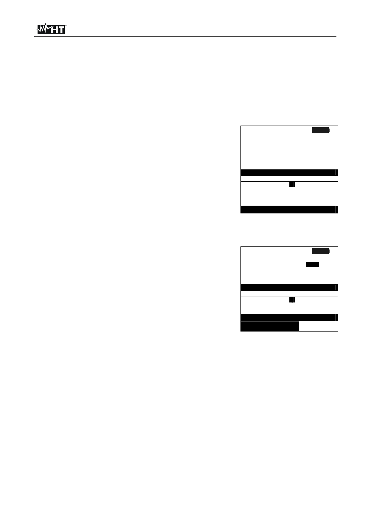
I-V400 - SOLAR I-V
30
ABC
010
S
009
004
C
ABC
7. STORING DATA
The meter allows storing 99 results of PV checks (only SOLAR I-V) and 249 tests of I-V
curve in its internal memory. In the PV check operation it’s also possible to save the
instantaneous values at display. The saved data can be recalled at display and deleted in
each moment, and can be associated (for I-V curve test) to reference numerical markers
relevant to the installation name, the PV string and the PV module (max 255 markers).
7.1. SAVING TEST RESULTS OF PV CHECKS (ONLY SOLAR I-V)
1. Press SAVE key with a measured result shown at display
or for saving the instantaneous values. The right screen
with a virtual keyboard is displayed by the meter
2. Use the arrow keys (,) and ( , ) to fit a short
description (max 12 chars) relative to the PV check
3. Press SAVE key to store the result of test or ESC/MENU
key to exit without saving
7.2. SAVING TEST RESULTS OF I-V CURVE TEST
1. Press SAVE key with a measured result shown at display.
The following screen is displayed where the herewith items
are shown:
The first memory location available (“Measurement”)
The numerical marker “Installation”
The numerical marker “String”
The numerical marker “Module”
The field “Comment” where the operator can include a
short description (max 14 char) by using virtual keyboard
2. Use the arrow keys (,) to select the items and (,) to set the numeric value of the
markers and to use the virtual keyboard. “Comments” field modifications are possible
only by changing the number of the “Installation” marker inserting one among the
available markers
3. Press ENTER to digit any character of the desired name
4. Press SAVE key to store the result of test or ESC/MENU key to exit without saving.
15/05/10 15:34:26
PRp 0.851
Irr 827 W/m2
Pnom 3.500 kW
Tc 45 °C
Te
DEFGHI
ABCDEFGHI J K L M N O P
QRST UVWXYZ- +0123
4 5 6 7 8 9 SPACE DEL
SAVE for store data
15/05/10 15:34:26
Measurement: 007
Installation:
omment:
DEFGHI
ABCDEFGHI J K L M N O P
QRST UVWXYZ- +0123
4 5 6 7 8 9 SPACE DEL
SAVE for store data
Comment
KEYBOARD
tring:
Module:
KEYBOARD
°C
MEM – IV
EN - 58
Page 61
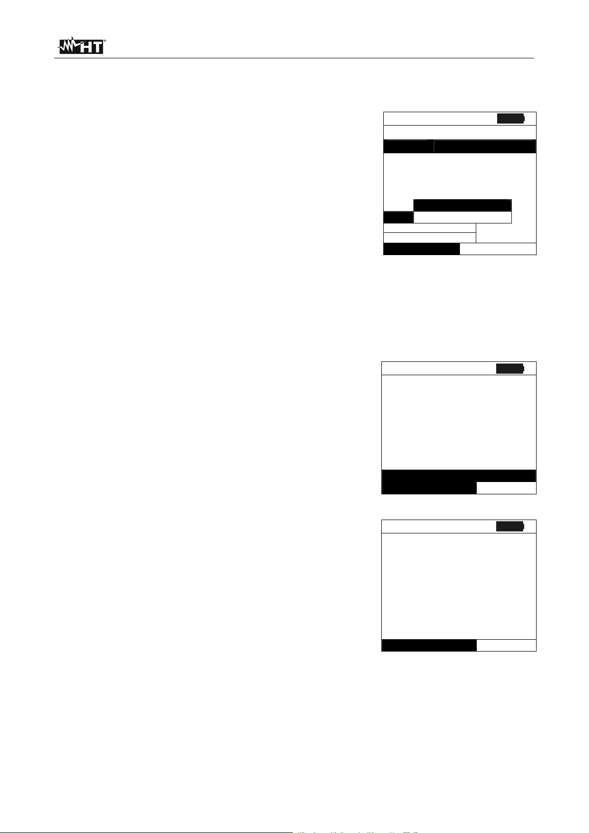
I-V400 - SOLAR I-V
7.3. MANAGING THE RESULTS
7.3.1. Recall data of PV checks at display (solo SOLAR I-V)
1. Press ESC/MENU key to back to the main menu, select
the “MEM” item and confirm with ENTER to access inside
the section od saved data
2. Using arrows keys (,) and the arrow key select the
item “Recall”, the item “Yield Test” and confirm with
ENTER for the visualization of PV checks results only
3. Using arrow key the herewith labels can be displayed:
TYPE means the type of saved data: “REC” for a
complete PV check, “*REC” when the values of
irradiance/temperature measured by SOLAR-02 are not
15/05/10 15:34:26
MEM TYPE
001 IST 08/04/2010
002 REC 13/05/2010
003 *REC 14/05/2010
Yield Test
Vie
Recall
Delete
Select
available for the meter and “IST” for the saving of
instantaneous values at display
DATA means the date/hour od saved data on meter
Comments means the description gives by the user
during the data saved operation
4. Select the “IST” data, the item “View” and confirm with
ENTER. The herewith screen is displayed:
5. Press the arrow keys ( ,) to access to the two available
screens
6. Press ESC/MENU to back to previous screen
7. Select the “REC” data, the item “View” and confirm with
ENTER. The herewith screen is displayed:
15/05/10 15:35:00
Pdc 3.125 kW
Vdc 389 V
Idc 8.01 A
ndc 0.88 °C
Pac 3.012 kW
Vac 231 V
Iac 13.03 A
nac 0.96
Select
8. Press the arrow keys ( ,) to access to the two available
screens
9. The final values of PV check relative to the maximum
efficiency condition detected are displayed
10. Press ESC/MENU to back to previous screen
11. Selecting the “*REC” data, the item “View” and confirm
with ENTER the message “Unable to execute analysis” is
displayed due to the missed of irradiance/temperature
values recorded by SOLAR-02. The partial values of
this measurement are only visible after downloading
the data onto PC (see § 8)
15/05/10 15:35:00
Pdc 3.125 kW
Vdc 389 V
Idc 8.01 A
ndc 0.88 °C
Pac 3.012 kW
Vac 231 V
Iac 13.03 A
nac 0.96
Select
I-V Test
MEM - EFF
Analysis results
EFF
EFF
EN - 59
Page 62

I-V400 - SOLAR I-V
7.3.2. Recall data of I-V curve tests at display
1. Press ESC/MENU key to back to the main menu, select
the “MEM” item and confirm with ENTER to access inside
the section od saved data
2. Using arrows keys (,) and the arrow key select the
item “Recall”, the item “I-V Test” and confirm with ENTER
for the visualization of I-C curve results only
3. The “DATA” label means the date/hour od saved data on
meter
4. Use arrow key to select the “Comments” label
5. The description gives by the user during the data saved
operation (see § 7.2) is displayed
6. The symbol “*” near the number of measure means that
the meter have performed the I-V curve test with recording
of irradiance/temperature values by use of remote unit
SOLAR-02, but this values did not transferred or are not
available. For this measurements the translated STC
values won’t be available
7. By means of the arrow key , select the “parameters”
label.
8. The markers relevant to Installation, String and Module
selected by the user during the saving procedure (§ 7.2)
are shown on the display.
9. Press ESC/MENU to exit the screen and to go back to the
main menu.
15/05/10 15:34:26
MEM DATA
001 08/04/2010 10:38
002 13/04/2010 12:15
Yield Test
Vie
Recall
Delete
Select
I-V Test
MEM I - V
15/05/10
15:34:26
MEM Comments
001 MODULE # 1
002* MODULE # 2
Select
15/05/10
15:34:26
MEM IMP STR MOD
001
002
MEM I - V
001 001 001
001 001 002
Select
MEM – IV
EN - 60
Page 63

I-V400 - SOLAR I-V
–
Avg
C
7.3.2.1. View data – Numerical screens
1. Select a row corresponding to a saved result and press
ENTER to access the § for the display of stored data. The
herewith screen shows a list of saved tests.
2. Select the “View” item and press ENTER to open the
section of data visualization in the herewith modes:
Numeric screens of parameters measured at the STC
conditions and at the operative conditions (OPC)
Graphic screens relative to the I-V curves saved at STC
and OPC conditions
3. The first screen shows the values of measured
parameters, referred to 1 module, translated to the
standard conditions (STC) according to § 6.2.3
4. Press arrow key , select by means of arrow keys (,)
the option “OPC – Avg” and press ENTER.
5. The meter shows the values measured on a string at the
real operating conditions (OPC). The values are averaged
on a single module (corresponding to the total values
should the string be made of a single module).
6. Press arrow key in the first screen, select the option
“OPC” by means of arrow keys (,) and press ENTER.
15/05/10 15:34:26
MEM INS STR MOD
001 001 001 001
002 001 001 002
View
Delete
Select
15/05/10 15:34:26
Voc 48.0 V
Vmpp 39.8 V
Impp 5.24 A
Isc 5.60 A
Pmax 208 W
FF 0.78 %
DPmax STC
OPC – Avg
Data OPC
I-V Graph
PWR Graph - OK
Select
15/05/10 15:34:26
Voc 46.9 V
Vmpp 39.0 V
Impp 4.85 A
Isc 5.22 A
Pmax 189 W
FF 0.77 %
Irr 927 W/m2
Tc 25.1 °C
MEM – IV
I – V
7. The meter shows the total values measured at the real
operating conditions (OPC) relative to the string under
test.
8. Press ESC/MENU key to exit and go back to the previous
screen.
EN - 61
Results @ OPC
Select
15/05/10 15:34:26
Voc 46.9 V
Vmpp 39.0 V
Impp 4.85 A
Isc 5.22 A
Pmax 189 W
FF 0.77 %
Irr 927 W/m2
Tc 25.1 °C
Results @ OP
Select
I – V
I – V
Page 64

I-V400 - SOLAR I-V
0
pp
60
208
0.78
OPC
g
OPC
–
O
g
C
7.3.2.2. View data – Graphic screens of I-V curve
1. With screen of numerical values relative to standard
conditions (STC) select the item “I-V Graph” by means of
arrow key and press ENTER or the arrow key .
2. Select the “STC” option and press ENTER.
3. The herewith screen is shown by the meter.
4. The graph is the I-V curve relative to the object under test
translated to the standard conditions (STC) and referred
to 1 module.
5. Press ESC/MENU key to exit the screen and to go back
to the memory section.
15/05/10 15:34:26
Voc 48.
Vmpp 39.8 V
Im
Isc 5.
Pmax
FF
DPmax STC
Data
I-V Graph
PWR Graph -OK
Select
15/05/10 15:34:26
5.24 A
– Av
V
A
W
%
I – V
6. With screen of numerical values measured by meter
select the item “I-V Graph” by means of arrow key and
press ENTER or the arrow key .
7. Select the option “OPC – Avg” and press ENTER. The IV curve graph of a string measured at the real operative
conditions (OPC) and displayed by the meter is averaged
on a single module.
8. Press ESC/MENU key to exit the screen and to go back
to the memory section
9. With screen of numerical values measured by meter
select the item “IV Graph” by means of arrow key and
press ENTER or the arrow key .
10. Select the option “ OPC” and press ENTER. The I-V curve
graph measured at the real operative conditions (OPC)
and displayed by the meter corresponds to the total
value relative to the string under test.
11. Press ESC/MENU key to exit from screen and back to the
memory §
I-V Graph @ STC
Select
15/05/10 15:34:26
I-V Graph @ OPC -Av
Select
15/05/10 15:34:26
I-V Graph @ OP
Select
I – V
I – V
I – V
K
EN - 62
Page 65

I-V400 - SOLAR I-V
0
pp
60
208
0.78
0
STC
G
O
g
OPC
C
–
O
g
C
7.3.2.3. View data – Graphic screens of power
1. With screen of numerical values measured by the meter
select the item “PWR Graph” by means of arrow key
and press ENTER or the arrow key .
2. Select the option “STC” and press ENTER.
3. The herewith screen is shown by the meter.
4. The graph shows values of output power from
module/string translated to the standard conditions (STC).
5. Press ESC/MENU key to exit the screen and to go back
to the memory §.
15/05/10 15:34:26
Voc 48.
Vmpp 39.8 V
Im
Isc 5.
Pmax
FF
DPmax
Data
I-V
PWR
Select
15/05/10 15:34:26
5.24 A
.5 %
PV – Av
V
A
W
%
I – V
6. With screen of numerical values measured by meter,
select the item “PWR Graph” by means of arrow key
and press ENTER or the arrow key .
7. Select the option “OPC – Avg” and press ENTER. The
meter shows the graph of output power from a single
module of a string measured at the real operative
conditions (OPC).
8. Press ESC/MENU key to exit the screen and to go back
to the memory §.
9. With screen of numerical values measured by the meter
select the item “PWR Graph ” by means of arrow key
and press ENTER or the arrow key .
10. Select the option “OPC” and press ENTER. The meter
shows the graph of total output power relevant to the
string under test measured at the real operative
conditions (OPC).
11. Press ESC/MENU key to exit the screen and to go back
to the memory §.
PWR Graph @ ST
Select
15/05/10 15:34:26
PWR Graph @ OPC-Av
Select
15/05/10 15:34:26
PWR Graph @ OP
Select
I – V
I – V
I – V
K
EN - 63
Page 66

I-V400 - SOLAR I-V
15/05/10
7.3.3. Delete data
1. Press ENTER key in the memory § to show the submenu
2. Select the “Delete” item and press the arrow key . The
options below are shown by the meter:
Del. Last delete the last measurement saved
Del. All delete all data in the memory
3. Select the desired option with arrow keys (,) and
confirm with ENTER
4. Press ESC/MENU to exit the screen and go back to main menu
15/05/10 15:34:26
MEM DATA
001
View Del. Last
Delete Del. All
Select
12:32
MEM – IV
EN - 64
Page 67

I-V400 - SOLAR I-V
8. CONNECTING THE INSTRUMENT TO A PC
CAUTION
The connection between instrument and PC is realized by means of cable
C2006.
In order to transfer the data onto a PC it is necessary to install beforehand
both the management software Topview and the drivers of cable C2006 on
the PC itself.
Before connecting, it is necessary to select the port to be used and the right
baud rate (57600 bps) on the PC. To set these parameters, start the
TopView software and refer to the program's on-line help.
The selected port must not be engaged by other devices or applications,
e.g. a mouse, a modem, etc.
Optical port emits invisible LED radiations. Do not bring the beam at eye
level. Class 1M LED apparatus according to IEC/EN 60825-1
To transfer the saved data to the PC, follow this procedure:
1. Switch on the instrument by pressing the ON/OFF key
2. Connect the instrument to the PC via the provided optical/USB cable C2006.
3. Press ESC/MENU key to open the main menu.
4. By means of arrow keys (,) select the item “PC Connection” to access the PC
mode section and confirm with ENTER
15/05/10 15:34:26
I - V
I-V Test
EFF Yield Test
SET
Settings
DB
Modules
MEM
Data Recall
PC
PC Connection
ENTER to select.
MENU
5. The herewith screen is shown by the meter:
15/05/10 15:34:26
PC – RS232
6. Use the data management software TopView for transferring the content of the
instrument memory to the PC (see on-line help of this software for all details)
EN - 65
MENU
Page 68

I-V400 - SOLAR I-V
9. MAINTENANCE
9.1. GENERAL
The instrument you purchased is a precision instrument. When using and storing it, please
observe the recommendations listed in this manual in order to prevent any possible
damage or danger. Do not use the instrument in environments with high humidity levels or
high temperatures. Do not directly expose it to sunlight. Always switch off the instrument
after using it. Should the instrument remain unused for a long time, remove batteries in
order to prevent liquids from leaking out of them, and the instrument internal circuits from
being damaged.
9.2. BATTERY REPLACEMENT
When the low battery symbol “ ” appears on the LCD display, or if during a test the
meter gives the message “low battery”, it is necessary to replace the batteries.
This operation must be carried out by skilled technicians only. Before
carrying out this operation, make sure that all cables have been removed
from the input leads.
1. Swicth off the instrument by pressing and holding the ON/OFF key.
2. Remove the cables from the input leads.
3. Unscrew the cover fastening screw from the battery compartment and remove it.
4. Remove all the batteries from the battery compartment and replace with new batteries
of the same type only (§ 10.4) making sure to respect the indicated polarities.
5. Restore the battery compartment cover into place and fasten it by means of the
relevant screw.
6. Do not dispose of the used batteries into the environment. Use relevant containers for
disposal.
9.3. INSTRUMENT CLEANING
Use a dry and soft cloth to clean the instrument. Never use wet cloths, solvents, water, etc.
9.4. END OF LIFE
CAUTION
CAUTION: this symbol indicates that the equipment, the batteries and its
accessories must be collected separately and disposed of in the right way.
EN - 66
Page 69

I-V400 - SOLAR I-V
10. TECHNICAL SPECIFICATIONS
10.1. YIELD TEST TECHNICAL FERATURES (ONLY SOLAR I-V)
Accuracy is calculated as [%reading+(number of dgt) * resolution] at 23°C ± 5°C, <80%HR
VDC Voltage
Range [V] Resolution [V] Accuracy
15.0 999.9
AC TRMS Voltage
Range [V] Resolution [V] Accuracy
50.0 265.0
Max crest factor: 1.5
DC Current (by external transducer clamp)
Range [mV] Resolution [mV] Accuracy
-1100 -5
5 1100
The value of current is ALWAYS displayed with positive sign ; The value of current transduced in voltage less then 5mV is zeroed
AC TRMS Current (by external transducer clamp)
Range [mV] Resolution [mV] Accuracy
1 1200
Max crest factor: 2.0 ; The value of current transduced in voltage less then 5mV is zeroed
FS DC and AC clamp [A] Resolution [A]
1< FS 10
10< FS 100
100< FS 1000
DC Power (Vmis > 150V)
FS clamp [A] Range [W] Resolution [W] Accuracy
1< FS 10
10< FS 100
100< FS 1000
Vmis = voltage at which power is measured ; Imis = measured current
0.000k 9.999k
10.00k 99.99k
0.000k 9.999k
10.00k 99.99k
0.00k 99.99k
100.0k 999.9k
AC Power (Vmis > 200V, PF=1)
FS clamp [A] Range [W] Resolution [W] Accuracy
1< FS 10
10< FS 100
100< FS 1000
Vmis = voltage at which power is measured ; Imis = measured current
0.000k 9.999k
10.00k 99.99k
0.000k 9.999k
10.00k 99.99k
0.00k 99.99k
100.0k 999.9k
Frequency
Range [Hz] Resolution [Hz] Accuracy
47.5 63.0
Irradiance (with reference reference cell)
Range [mV] Resolution [mV] Accuracy
1.0 100.0
Temperature (with auxiliary probe)
Range [°C] Resolution [°C] Accuracy
-20.0 100.0
0.1
0.1
0.1
0.1
(0.5rdg + 2dgt)
(0.5rdg + 2dgt)
(0.5rdg + 0.6mV)
47.5 63.0
Minimum read value [A]
DC AC
0.001 0.05 0.01
0.01 0.5 0.1
0.1 5A 1
0.001k
0.01k
(0.7rdg + 3dgt)
(Imis < 10%FS)
0.001k
0.01k
0.01k
0.1k
0.001k
0.01k
0.001k
(0.7rdg)
(Imis 10%FS)
(0.7rdg + 3dgt)
(Imis < 10%FS)
0.01k
0.01k
0.1k
0.1
0.1
0.1
(0.7rdg)
(Imis 10%FS)
(0.2rdg + 1dgt)
(1.0rdg + 5dgt)
(1.0rdg + 1°C)
EN - 67
Page 70

I-V400 - SOLAR I-V
10.2. I-V TEST TECHNICAL FEATURES (I-V AND IVCK)
I-V: DC Voltage @ OPC
Range [V] (***) Resolution [V] Uncertainty (***)
5.0 999.9
(***) The I-V curve and Rs measurements start for VDC > 15V and the accuracy is defined for VDC > 20V
0.1
(1.0rdg + 2dgt)
I-V: DC Current @ OPC
Range [A] Resolution [A] Uncertainty
0.10 10.00
0.01
(1.0rdg + 2dgt)
I-V: DC Power @ OPC (Vmpp > 30V, Impp > 2A)
Range [W] (*, **) Resolution [W] Uncertainty
50 9999
Vmpp = Maximum power voltage, Impp = Maximum Power Current
(*) Max measurable value of Power must include FF value(~ 0.7) Pmax = 1000V x 10A x 0.7 = 7000W
(**) Test is stopped and the message “Thermal instability” occurs if the instrument detects Voltage > 700V and Current I >3A, I > -
0.038*V + 37.24 - 0.5
1
(1.0rdg + 6dgt)
I-V: DC Voltage @ STC, IVCK: DC Voltage @ OPC and @ STC
Range [V] Resolution [V] Uncertainty (*,**)
5.0 999.9
0.1
4.0rdg + 2dgt)
I-V: DC Current @ STC, IVCK: DC Current @ OPC and @ STC
Range [A] Resolution [A] Uncertainty (**)
0.10 10.00
0.01
(4.0 rdg + 2 dgt)
I-V: DC Power @ STC (Vmpp > 30V, Impp > 2A)
Range [W] Resolution [W] Global Uncertainty (**)
50 9999
Vmpp = Maximum power voltage, Impp = Maximum Power Current
(*) Measurements start for VDC > 15V and the accuracy is defined for VDC > 20V
(**) Test conditions:
Test cond.: Steady Irrad.700W/m
Global accuracy include contribute of solar sensor and its measuring circuit
2
, spectrum AM 1.5,solar incidence vs perpendicular. 25°, Cells Temp. [15..65°C]
1
(5.0 rdg + 1 dgt)
Irradiance (with reference cell)
Range [mV] Resolution [mV] Accuracy
1.0 100.0
0.1
(1.0rdg + 5dgt)
Temperature (with auxiliary probe)
Range [°C] Resolution [°C] Accuracy
-20.0 100.0
0.1
(1.0rdg + 1°C)
10.3. SAFETY SPECIFICATIONS
10.3.1. General
Instrument safety: IEC/EN61010-1
Technical literature: IEC/EN61187
Accessory safety: IEC / EN61010-031
Measurements: IEC/EN60891 (I-V curve test)
IEC/EN 60904-5 (Temperature measurement)
Insulation: double insulation
Pollution level: 2
Category of measure: CAT II 1000V DC, CAT III 300V to earth
Max 1000V among inputs P1, P2, C1, C2
EN - 68
Page 71

I-V400 - SOLAR I-V
10.4. GENERAL CHARACTERISTICS
Display and memory
Type of display: LCD custom, 128x128 pxl, backlighted
Memory capacity: 256kbytes
Saved data: 99 yield tests (SOLAR I-V only); 249 I-V, 999IVCK
PC interface: optical / USB
PV Yield Test (only SOLAR I-V)
Integration period (IP): 5,10,30,60,120,300,600,900,1800,3600s
Memory authonomy SOLAR-02: approx 1.5 hours (@ PI = 5s)
approx 8 days (@ PI = 600s)
Max distance RF connection: 1m (3 ft)
Memory of SOLAR-02 - MPP300: approx. 1.5 hours (@ PI = 5s)
approx. 8 days (@ PI = 600s)
Power supply
Battery type: 6 x1.5 V alkaline type AA L&06
Low battery indication: symbol “ “ is displayed
Battery life: approx 120 hours (PV Yield test)
>249 I-V curve test, 999 IVCK test
Auto power off: after 5 minutes of idleness
Mechanical data
Size: 235(L)x165(W)x75(H)mm ; 9(L) x 6(W) x 3(H) in
Weight (batteries included): 1.2kg (42 ounces)
10.5. ENVIRONMENT CONDITIONS
Reference temperature: 23° ± 5°C (73°F ± 41°F)
Working temperature: 0 ÷ 40°C (32°F ÷ 104°F)
Relative humidity allowed: <80%RH
Storage temperature: -10 ÷ 60°C (14°F ÷ 140°F)
Storage humidity: <80%RH
Max height of use: 2000m (6562 ft) (*)
(*) Information about the use of meter at altitude from 2000 to 5000m
As for voltage inputs P1, P2, C1, C2 the instrument is to be considered downgraded to
overvoltage category CAT I 1000V DC and CAT II 300V to ground, max 1000V among
inputs. Markings and symbols indicated on the instrument are to be considered valid when
using it at altitude lower than 2000m
CAUTION
This instrument complies with the prescriptions of the European directive on low
voltage 2006/95/CE (LVD) and EMC 2004/108/CE
10.6. ACCESSORIES
See enclosed Packing List
EN - 69
Page 72

I-V400 - SOLAR I-V
11. APPENDIX
11.1. TESTING PHOTOVOLTAIC SYSTEMS
According to the requirements of the laws in force, the result of the test depends on
settings about Temperature effects compensation and PRp calculations:
Corr.Typ
e
Tmod
Tamb
or
Tenv
Tcel value PRp calculation
Tcel = PV Module Temp. measured
Tcel = PV module Temp. calculated
G
NOCT
20TambTcel
800
P
PRp
p
Rfv
ca
G
G
p
STC
2
P
n
Guidelin
e
CEI
82-25
(Italian
Guideline)
nDC
Tcel = PV Module Temp. measured
G
PRp
G
STC
p
1
100
T
cel
25
P
ca
P
n
- - -
where:
Symbol Description Meas. unit
G
p
G
STC
P
n
P
ca
Rfv
2
NOCT Normal Operating Cell Temperature (@ 800W/m2, 20°C,
40)-(Tcel- 1
100
C)40Tcel (if 1
C)40Tcel (if
Irradiance on PV module surface
Standard Irradiance = 1000
Nominal Power = sum of all power module (Pmax )
included in the part of PV plant under test
AC Active Power measured
Thermal Corrective factor
Absolute value of Pmax thermal coefficient
AM=1.5, vel. Aria =1m/s).
W/m
W/m
kW
kW
2
2
C%/
C%/
Previous relationship are valid if Irradiance > Min Irraddiance value and the Irradiance
values are “steady”: if IP 1min (Irr max – Irr min) < 20W/m2
The final OUTCOME can be:
Non-displayable: if the obtained values are inconsistent (e.g. PRp >1.15) or if
irradiation has never reached a steady value > minimum threshold set.
The maximum performance point (PRp) of the system
The highest performance (maximum value of PRp) is detected according with previous
relationships.
EN - 70
Page 73

I-V400 - SOLAR I-V
11.2. NOTES ON MPPT (MAXIMUM POWER POINT TRACKER)
Solar irradiation on a surface such as the surface of a photovoltaic system has extremely
variable characteristics, since it depends on the position of the sun with respect to the
surface and on atmospheric conditions (typically, on the presence of clouds). A
photovoltaic module presents, for different solar irradiation values, and for different
temperature values, a range of characteristic curves of the type shown in the following
figure. In particular, the figure shows three I-V curves (in bold) which correspond to three
values (1000, 800, 600W/m2) of solar irradiation.
On each characteristic curve there is one single point in which the power transfer towards
a hypothetical charge supplied by the photovoltaic module is maximized. The maximum
power point corresponds to the voltage-current pair for which the product V*I is maximum,
where V is the value of voltage at the module’s terminals and I is the current which runs in
the circuit obtained by closing the module on a hypothetical charge.
With reference to the figure above, the product V*I is represented, for the three solar
irradiation values mentioned above, through the three curves in thinner lines.
The figure shows that, as stated above, these curves only have one single maximum point.
For example, for 1000W/m2, the maximum power point corresponds to a voltage value of
approx. 36V and to a current value of approx. 5.5A.
Obviously, if the power provided by the system is maximized, it is possible to make the
most of the system, both in case the system is connected to mains, and in case it is standalone.
MPPT is an inbuilt device in the inverters. It typically reads the voltage and current values
at any instant, calculates their product (i.e. the power in Watts) and, by causing small
variations in the conversion parameters (duty cycle), it is capable of determining, by
comparison, if the photovoltaic module is working in maximum power conditions or not.
According to the result, it operates again on the circuit in order to bring the system to an
optimal condition.
EN - 71
Page 74

I-V400 - SOLAR I-V
The reason why MPPTs are used is simple: a photovoltaic system without MPPTs may
operate anyway; however, with the same solar irradiation, it provides less energy.
There are inverters with 1, 2 or also 3 inbuilt MPPTs available on the market. Typically, the
inverters with more than one MPPT are used in systems where:
- the different photovoltaic systems it consists of “forcibly” have different inclinations
or directions. In this way, each single MPPT manages its own photovoltaic field,
maximizing its performance for the corresponding irradiation and temperature
characteristics (without being influenced by the other photovoltaic fields).
- a greater service continuity is sought. With more MPPTs it is possible to put one
single photovoltaic field out of service, while the others continue producing energy
towards the remaining MPPTs.
11.3. THEORETICAL ASPECTS OF THE I-V CURVE MEASUREMENT
The I-V curve test is performed as described below:
The meter performs the I-V curve measurement of the PV module connected to it,
further to the real time measurement of irradiance and module temperature
The results of measurements are automatically “translated” to the standard conditions
(STC) of irradiance at 1000 W/m2 and module temperature at 25°C. The accuracy
indicated in this manual is granted under condition indicated in § 10.2.
The meter performs a comparison between the maximum nominal power, with the
margin of percentage tolerance declared by the module’s manufacturer, which is
included in the kind of module selected on the meter from the database (§ 5.3.1), and
the measured value
If the comparison of power is within the declared tolerance, the final response of the
meter will be “OK” or will be “NO OK” in the opposite case, and the module will not be
complying with the specifications declared by the manufacturer (§ 6.2.3)
11.3.1. Theoretical aspects of Rs measurement
The test about serial resistance Rs is used in order to perform an exact measurement in
real time of this parameter and then add this value to the definition of the PV module’s
specifications in the internal database of the meter, in compliance with the IEC/EN60891
standard.
EN - 72
Page 75

I-V400 - SOLAR I-V
12. SERVICE
12.1. WARRANTY CONDITIONS
This instrument is guaranteed against any defect in material and manufacturing in
compliance with the general sales terms and conditions. Throughout the period of
guarantee all defective parts may be replaced and the manufacturer reserves the right to
repair or replace the product.
If the instrument is to be returned to the after-sales service or to a dealer transportation
costs are on the customer’s behalf. Shipment shall be however agreed upon. A report
must always be enclosed to a rejected product stating the reasons of its return. To ship the
instrument use only the original packaging material; any damage that may be due to nooriginal packing shall be charged to the customer. The manufacturer declines any
responsibility for damages caused to persons and/or objects.
Warranty is not applied in the following cases:
Repair and/or replacement of accessories and battery (not covered by warranty)
Any repair that might be necessary as a consequence of a misuse of the instrument or
of its use with no compatible devices.
Any repair that might be necessary as a consequence of improper packaging.
Any repair that might be necessary as a consequence of service actions carried out by
unauthorized personnel.
Any modification of the instrument carried out without the authorization of the
manufacturer.
Use not provided for in the instrument’s specifications or in the instruction manual.
The contents of this manual may not be reproduced in any form whatsoever without the
manufacturer’s authorization.
All our products are patented and their trade marks registered. The manufacturer
reserves the right to modify the product specifications and prices if this is aimed at
technological improvements.
12.2. SERVICE
If the instrument does not operate properly, before contacting the after-sales service check
cables as well as test leads and replace them if necessary. Should the instrument still
operate improperly check that the operation procedure is correct and conforms with the
instructions given in this manual.
If the instrument is to be returned to the after-sales service or to a dealer, transportation
costs are on the customer’s behalf. Shipment shall be however agreed upon. A report
must always be enclosed to a rejected product stating the reasons of its return. To ship the
instrument use only the original packaging material; any damage that may be due to nonoriginal packing shall be charged to the customer.
EN - 73
Page 76

Via della Boaria 40
48018 – Faenza (RA) - Italy
Tel: +39-0546-621002 (4 linee r.a.)
Fax: +39-0546-621144
email: ht@htitalia.it
http://www.ht-instruments.com
 Loading...