

Page 1
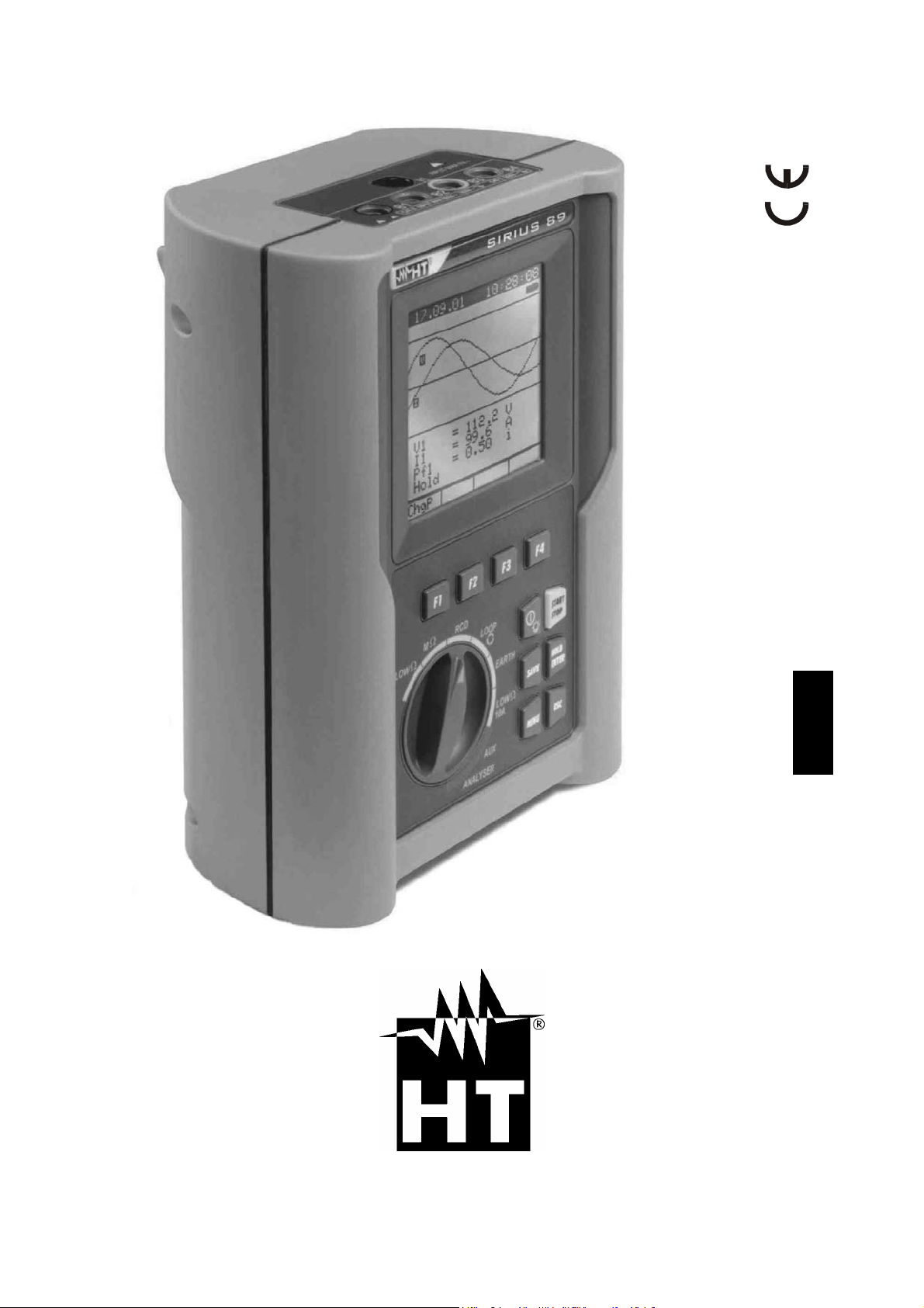
SIRIUS89N
User’s Manual
© Copyright HT ITALIA 2008 Release 2.02 - 21/01/2008
Page 2

Page 3

SIRIUS89N
TABLE OF CONTENTS:
1. SAFETY PRECAUTIONS AND PROCEDURES.......................................................................................... 4
1.1. Forwards..................................................................................................................................................................4
1.2. Preliminary Instruction.............................................................................................................................................4
1.3. During Use...............................................................................................................................................................5
1.4. After Use..................................................................................................................................................................5
2. GENERAL DESCRIPTION........................................................................................................................... 6
2.1. Introduction..............................................................................................................................................................6
2.2. Functions...................................................................................................................... ...........................................6
3. PREPARATION FOR USE........................................................................................................................... 7
3.1. Initial Control............................................................................................................................................................7
3.2. Power Supply...........................................................................................................................................................7
3.3. Calibration................................................................................................................................................................8
3.4. Storage....................................................................................................................................................................8
4. INSTRUMENT DESCRIPTION..................................................................................................................... 9
4.1. Display Description................................................................................................................................................10
4.2. Initial Screen..........................................................................................................................................................10
4.3. Backlight function...................................................................................................................................................10
5. INITIAL SETTINGS......................................................................................................................................11
5.1. How to Adjust the Contrast....................................................................................................................................11
5.2. How to Set Date and Time.....................................................................................................................................11
5.3. How to Set the Language......................................................................................................................................11
5.4. Reset.....................................................................................................................................................................12
6. SAFETY TEST FUNCTIONS.......................................................................................................................13
6.1. LOWΩ: Continuity Test with 200mA Test Current.................................................................................................13
6.1.1. Calibrating the test leads ("CAL" Mode)..........................................................................................................................14
6.1.2. Measurement Procedure.................................................................................................................................................15
6.1.3. Results of "AUTO" mode.................................................................................................................................................16
6.1.4. Results of "RT+" and "RT-" modes..................................................................................................................................16
6.1.5. "AUTO", RT+", "RT-" faulty cases....................................................................................................................................17
6.2. MΩ: Insulation resistance Measurement with 50V, 100V, 250V, 500V, 1000V Test Voltage......................................19
6.2.1. Measurement Procedure.................................................................................................................................................19
6.2.2. Results of "MAN" mode...................................................................................................................................................21
6.2.3. Results of "TMR" mode....................................................................................................................................................22
6.2.4. "MAN" and "TIMER" mode faulty cases...........................................................................................................................23
6.3. RCD: Test on "A" and "AC" RCDs Type................................................................................................................24
6.3.1. Tripping times for the general and selective RCDs..........................................................................................................26
6.3.2. Measurement procedure..................................................................................................................................................27
6.3.3. RCD Faulty cases............................................................................................................................................................32
6.4. LOOP : Measurement of Line Impedance, Fault loop Impedance, Prospective Short Circuit Current
Calculation and Phase Sequence Indicator...........................................................................................................37
6.4.1. High resolution Impedance measurement (0.1mΩ)........................................................................................................37
6.4.2. Measurement procedure and results of "P-N" mode.......................................................................................................38
6.4.3. Measurement procedure and results of "P-P" mode........................................................................................................39
6.4.4. Measurement procedure and results of "P-PE" mode.....................................................................................................40
6.4.5. Measurement procedure and results of " RA" mode...................................................................................................42
6.4.6. Measurement procedure and results of " " mode.......................................................................................................43
6.4.7. LOOP Faulty Cases..................................................................................................................................................44
6.5. EARTH: Soil Resistance and Resistivity Measurements.......................................................................................49
6.5.1. Measurement procedure and results of "2-W"and "3-W" mode.......................................................................................50
6.5.2. Measurement procedure and results of "ρ" mode...........................................................................................................51
6.5.3. "2-W", "3-W" and "ρ" faulty cases....................................................................................................................................52
7. AUX: MEASUREMENT WITH EXTERNAL PROBES.................................................................................55
7.1. Environmental parameter and leakage current: REAL TIME MEASUREMENT....................................................56
7.2. Environmental parameter and leakage current: RECORDING..............................................................................58
EN - 1
Page 4

SIRIUS89N
7.2.1. AUX Basic setting: RECORDER CONFIG.......................................................................................................................58
7.2.2. RECORDING: setting of Typical Configurations..............................................................................................................60
7.3. Sound level measurement procedure....................................................................................................................61
8. ANALYZER .................................................................................................................................................63
8.1. Basic Setting: ANALYZER CONFIG......................................................................................................................64
8.1.1. Type of electrical system under test................................................................................................................................64
8.1.2. How to set the fundamental frequency............................................................................................................................64
8.1.3. How to set the current range ...........................................................................................................................................64
8.1.4. Clamp Type .....................................................................................................................................................................64
8.1.5. How to set the value of the transformer voltage ratio (TV RATIO)..................................................................................65
8.1.6. How to enable/disable the password...............................................................................................................................65
8.2. Basic Setting: RECORDER CONFIG ....................................................................................................................66
8.3. Analyzer functions..................................................................................................................................................73
8.4. "VOLTAGE" Function.............................................................................................................................................73
8.4.1. Symbols...........................................................................................................................................................................73
8.4.2. "METER" mode................................................................................................................................................................74
8.4.3. "HARM" mode..................................................................................................................................................................75
8.4.4. "WAVE" mode..................................................................................................................................................................76
8.5. "CURRENT" Function............................................................................................................................................77
8.5.1. Symbols...........................................................................................................................................................................77
8.5.2. “METER" mode................................................................................................................................................................78
8.5.3. “HARM" mode..................................................................................................................................................................79
8.5.4. "WAVE" mode..................................................................................................................................................................80
8.6. "POWER" Function................................................................................................................................................81
8.6.1. Symbols...........................................................................................................................................................................81
8.6.2. "METER" mode................................................................................................................................................................82
8.6.3. "WAVE" mode..................................................................................................................................................................83
8.7. "ENERGY" Function..............................................................................................................................................84
8.7.1. Symbols...........................................................................................................................................................................84
8.7.2. "METER" mode................................................................................................................................................................85
8.8. Measuring Procedures ...........................................................................................................................................86
8.8.1. Using the Instrument in a Single Phase System..............................................................................................................86
8.8.2. Using the Instrument in a Three Phase System..............................................................................................................87
9. SAVING RESULTS......................................................................................................................................88
9.1. Saving Safety Test Results....................................................................................................................................88
9.2. Saving Displayed Values of ANALYZER Function.................................................................................................88
10. RECORDINGS.............................................................................................................................................89
10.1. Start a Recording...................................................................................................................................................89
10.2. Setting Typical Configurations...............................................................................................................................90
10.2.1. Default Configuration.......................................................................................................................................................90
10.2.2. Typical Configurations.....................................................................................................................................................91
10.3. During a Recording................................................................................................................................................94
10.3.1. MENU key........................................................................................................................................................................94
10.3.2. Rotary Switch during a recording.....................................................................................................................................95
10.4. Stopping a Recording or an Energy Measurement................................................................................................95
11. INSTRUMENT'S MEMORY.........................................................................................................................96
11.1. Safety test memory................................................................................................................................................96
11.2. Analyzer memory...................................................................................................................................................97
12. CONNECTING THE INSTRUMENT TO A PC.............................................................................................98
13. MAINTENANCE ..........................................................................................................................................99
13.1. General Instruction ................................................................................................................................................99
13.2. Battery Replacement.............................................................................................................................................99
13.3. Instrument Cleaning...............................................................................................................................................99
13.4. End of life...............................................................................................................................................................99
14. TECHNICAL SPECIFICATIONS...............................................................................................................100
14.1. Technical Features ..............................................................................................................................................100
14.1.1. Safety Test functions.....................................................................................................................................................100
14.1.2. ANALYZER and AUX functions.....................................................................................................................................101
EN - 2
Page 5

SIRIUS89N
14.2. Standards ............................................................................................................................................................103
14.2.1. General..........................................................................................................................................................................103
14.2.2. Safety Test.....................................................................................................................................................................103
14.2.3. ANALYZER....................................................................................................................................................................103
14.2.4. AUX ...............................................................................................................................................................................103
14.3. General Specifications.........................................................................................................................................103
14.3.1. Mechanical Data............................................................................................................................................................103
14.3.2. Power supply.................................................................................................................................................................103
14.3.3. Display...........................................................................................................................................................................104
14.3.4. Memory..........................................................................................................................................................................104
14.4. ENVIRONMENT..................................................................................................................................................104
14.5. ACCESSORIES...................................................................................................................................................104
15. SERVICE...................................................................................................................................................105
15.1. WARRANTY CONDITIONS.................................................................................................................................105
15.2. SERVICE.............................................................................................................................................................105
16. PRACTICAL REPORTS FOR ELECTRICAL TESTS ...............................................................................106
16.1. Continuity Test On Protective Conductors...........................................................................................................106
16.2. Insulation Resistance Measurement of the Electrical Installations (250Vdc, 500Vdc, 1000Vdc).........................107
16.3. Check of the Circuit Separation................................................................................................ ...........................111
16.4. Earth Resistance Measurement in TT Systems ...................................................................................................114
16.5. Working Test of RCDs (Rcd, Rcd/Dc, Rcd S, Rcd/Dc S).....................................................................................115
16.6. Test of RCD Tripping Time (Rcd, Rcd/Dc)...........................................................................................................116
16.7. Measurement of Short-Circuit Fault Impedance (Zpn, Zpp)....................................................................................117
16.8. Fault Loop Impedance Measurement (Phase – Earth)........................................................................................117
16.9. Earth Resistivity Measurement.................................................................................................. ..........................118
16.10. Voltage Anomalies (Voltage S and Surge)..................................................................................................120
16.11. Voltage and current Harmonics...................................................................................................................120
16.11.1.
Theory..................................................................................................................................................................120
16.11.2.
Limit values for harmonics...................................................................................................................................122
16.11.3.
Presence of harmonics: causes...........................................................................................................................122
16.11.4.
Presence of harmonics: consequences...............................................................................................................123
16.12. Power and Power Factor definition..............................................................................................................123
16.12.1.
Conventions on powers and power factors..........................................................................................................125
16.12.2.
3 Phase 3 Wire System .......................................................................................................................................126
16.13. Measuring Method: outlines........................................................................................................................127
16.13.1.
Integration periods...............................................................................................................................................127
16.13.2.
Power factor calculations.....................................................................................................................................127
17. APPENDIX 1 – MESSAGES DISPLAYED................................................................................................128
18. APPENDIX 2 – RECORDABLE PARAMETERS: SYMBOLS ...................................................................129
EN - 3
Page 6
SIRIUS89N
1. SAFETY PRECAUTIONS AND PROCEDURES
1.1. FORWARDS
This apparatus conforms with safety standards EN61557 and EN 61010-1 relating to
electronic measuring instruments.
For your own safety as well as that of the apparatus you are recommended to
follow the procedures described in this instruction manual and carefully read all
the notes preceded by the symbol .
Strictly keep to the following instructions before and during measurements:
Do not take measurements in wet environments or dusty places.
Do not effect measurements in environments with explosive gas, fuels.
Keep you insulated from the object under test waiting for measuring.
Avoid any contact with exposed metal parts, ends of test leads not in use, circuits, etc.
Do not effect any measurement in case of unusual conditions of the instrument such as
deformation, breakage, leakage of substances, absence of display reading etc.
Do not use the External power supply adapter (optional code A0050) if you notice
deformation, or breakage in the case, in the wire or in the plugs.
Pay careful attention when measuring voltages exceeding 25V in particular places
(building yards, swimming pools, etc.) and 50V in ordinary places because of the risk of
electric shock.
Use only cables and accessories approved by HT Italia.
The following symbols are used in this manual:
Caution: refer to the instructions reported on this manual; improper use may
damage the apparatus or its components.
CAUTION
AC Voltage or Current.
Unidirectional pulsating Voltage or Current.
Rotary switch of the instrument.
1.2. PRELIMINARY INSTRUCTION
This instrument has been designed for use in environments with a pollution level 2 and
up to (and no more than) 2000 meters altitude.
It can be used for Safety Test on Installation with Overvoltage Category III 300V~
(phase to earth) and for voltage and current measurements on installations with
overvoltage category III 600 V~ phase to phase / 300 V~ phase to earth or CATII 350 V
phase to earth.
EN - 4
Page 7
SIRIUS89N
Please keep to the usual safety standards aimed at:
♦ Protecting against dangerous currents;
♦ Protecting the instrument against incorrect operations.
Only the accessories supplied with the instrument guarantee compliance with the
safety standards. Accordingly, they must be in good conditions and, if necessary, they
must be replaced with identical models.
Do not take measurements on circuits exceeding the specified current and voltage
limits.
Before connecting cables, crocodiles and clamps to the circuit under test, make sure
that the right function has been selected.
Do not effect any measurement under environmental conditions beyond the limits
specified in paragraph 14.4.
Check that batteries are not weak and placed correctly.
Before connecting test leads to the circuit under test, check that rotary switch position
is correct.
1.3. DURING USE
Please read carefully the following recommendations and instructions:
CAUTION
No compliance with the Warnings and/or Instructions may damage the
apparatus and/or its components or injure the operator.
Before selecting any function disconnect the test leads from the circuit under test.
When the instrument is connected to the circuit under test do not touch any unused
terminal.
Avoid to effect resistance measurements in the presence of external voltages; even
though the instrument is protected a too high voltage may cause malfunctions.
When measuring current, other currents located near the leads may affect the
measuring accuracy.
When measuring current, always position the wire in the very middle of the jaws in
order to obtain the highest accuracy.
A measured value remains constant if the "HOLD" function is active. Should you notice
that the measured value remains unchanged, disable the “HOLD” function.
CAUTION
The symbol " " shows the battery charge: When it is completely black the
battery are full charge, while the " " symbol indicate weak batteries. When
the batteries are too low to execute the test the instrument will show a warning
message. In the case interrupt testing and replace batteries following the
procedure described under paragraph 13.2. The instrument is capable of
keeping the data stored even though batteries are not installed. The
Instrument Date and Time settings aren't lost if you change the batteries
within 24hours.
1.4. AFTER USE
After use, turn off the instrument by pressing ON/OFF for a few seconds.
Remove batteries when the apparatus remains unused for long periods. Please follow
the storage instructions described at paragraph 14.4.
EN - 5
Page 8
SIRIUS89N
2. GENERAL DESCRIPTION
2.1. INTRODUCTION
Dear Customer, we thank you for your patronage. The instrument you have just purchased
will grant you accurate and reliable measurements provided that it is used according to the
present manual’s instructions.
The instrument was designed to grant the user the utmost safety conditions thanks to a
new concept assuring double insulation and over voltage category III.
2.2. FUNCTIONS
The instrument is able to perform eh following test:
LOWΩ: Continuity Test of Protection and Equalising conductors with test current
higher than 200mA and open circuit voltage ranging from 4V to 24V.
MΩ: Measurement of insulation resistance with DC test voltage 50V, 100V,
250V, 500V or 1000V.
RCD: Measurement on common and/or selective RCDs AC type (
type ( ) of the following parameters:
Tripping time.
Tripping current.
Contact voltage (U
t
).
Global earth resistance (Ra).
Under this mode the instrument can measure the overall earth resistance
without causing RCD tripping.
) and A
LOOP : Measurement of line and fault loop impedance with calculation of
prospective short circuit current, Measurement of fault loop impedance
between phase and earth and Global Earth resistance measurement
without RCD tripping and calculation of prospective short circuit current,
Indication of phase rotation sequence
EARTH Measurement of Earth Resistance and Resisivity using Earth rods.
AUX: Measurement and Recording of leakage current or environmental values
(temperature, humidity, Air Speed, Illuminance and Sound level).
ANALYZER: The Instrument allows the following operations:
Display in real time the electrical parameters of a single phase
systems and the harmonic analysis of voltage and current.
Conduct a direct Energy measurement (without memorizing).
Memorize (pressing SAVE key) the sampled values of the Parameters
present at instrument input generating a "Smp" record inside
instrument memory. It will be possible to analyze the memorized
data ONLY by transferring it to a PC.
Record simultaneously (pressing the START key after a proper
setting): RMS values of voltage, current, corresponding harmonics,
active, reactive and apparent powers, power factors and cosϕ, active,
reactive and apparent energies, voltage anomalies (voltage sag and
surge) with 10ms resolution. It will be possible to analyze the
recorded data ONLY by transferring them to a PC.
CAUTION
Please note the difference between memorize and record. These terms
will be used repeatedly in this manual. Please focus on their definitions and
distinctions.
EN - 6
Page 9
SIRIUS89N
3. PREPARATION FOR USE
3.1. INITIAL CONTROL
This instrument has been checked mechanically and electrically prior to shipment.
Any care has been taken to ensure that the instrument reaches you under safe conditions.
You are recommended, however, to carry our a rapid check to detect any possible
damage which might have been caused during transport. Should this be the case,
immediately contact HT Italia.
Check also that the packaging contains all the parts listed under paragraph 14.5. In case
of discrepancies contact the dealer.
In case you have to send the instrument back please follow the instructions reported in
paragraph 15.
3.2. POWER SUPPLY
The instrument can be powered by:
6 batteries 1.5V AA - LR6 series located in the compartment on the back of the
instrument (not included in the package). For battery life see paragraph 14.3.1.
An external power supply adapter (optional code A0050) to be used only for
ANALYSIS and AUX function. We recommend You to use only A0050 HT Power
Supply adapter.
For your own safety it's not allowed to use the external power supply
adapter during Safety Test (LOWΩ, MΩ, RCD, LOOP, EARTH rotary
Switch positions). If you press the START button the Instrument will
show the message "o REMOVE POWER".
The symbol
charge, while the
shows the battery charge: If it is completely "black" the battery are full
symbol indicate weak batteries. When the batteries are too low to
execute the test the instrument will show a warning message.
In the case interrupt testing and replace batteries following the procedure described under
paragraph 13.2. The instrument is capable of keeping the data stored even though
batteries are not installed. The Instrument Date and Time settings aren't lost if you
change the batteries within 24hours.
CAUTION
EN - 7
Page 10
SIRIUS89N
CAUTION
For recordings (ANALYSIS and AUX function) use ALWAYS the external
power supply adapter (optional code A0050) even the instrument allows the
operator to perform a recording using internal batteries. If during a recording
the external power supply adapter is de-energised, the instrument will
continue the recording using the internal battery power until the batteries
are exhausted (the data stored up to the point the instrument shuts down
won’t get lost). For this we recommend you ALWAYS insert a new set of
batteries before a long recording.
The instrument uses sophisticated algorithms to prolong the battery life. Particularly:
The instrument switches OFF the backlight Automatically after 5 seconds.
If the instrument is displaying in real time (and the external power supply adapter is not
connected), after about 5 minutes from the last key pressure or switch rotation the
instrument turns off automatically ("AUTOPOWER OFF" procedure).
If the instrument is recording or is measuring energy (and the external power supply is
not connected), after about 5 minutes from the last key pressure or switch rotation the
instrument starts a special procedure to save the batteries ("ECONOMY MODE"): the
instrument keeps recording but the display is turned off.
3.3. CALIBRATION
The instrument fulfils the technical specifications listed in this manual. The performance of
the specifications are guaranteed for one year.
3.4. STORAGE
In order to grant the accuracy of the measurements, after a period of storage in extreme
environmental conditions, wait for the time necessary so that the apparatus is back to
normal measuring conditions (see environmental specifications listed in paragraph 14.4).
EN - 8
Page 11
SIRIUS89N
4. INSTRUMENT DESCRIPTION
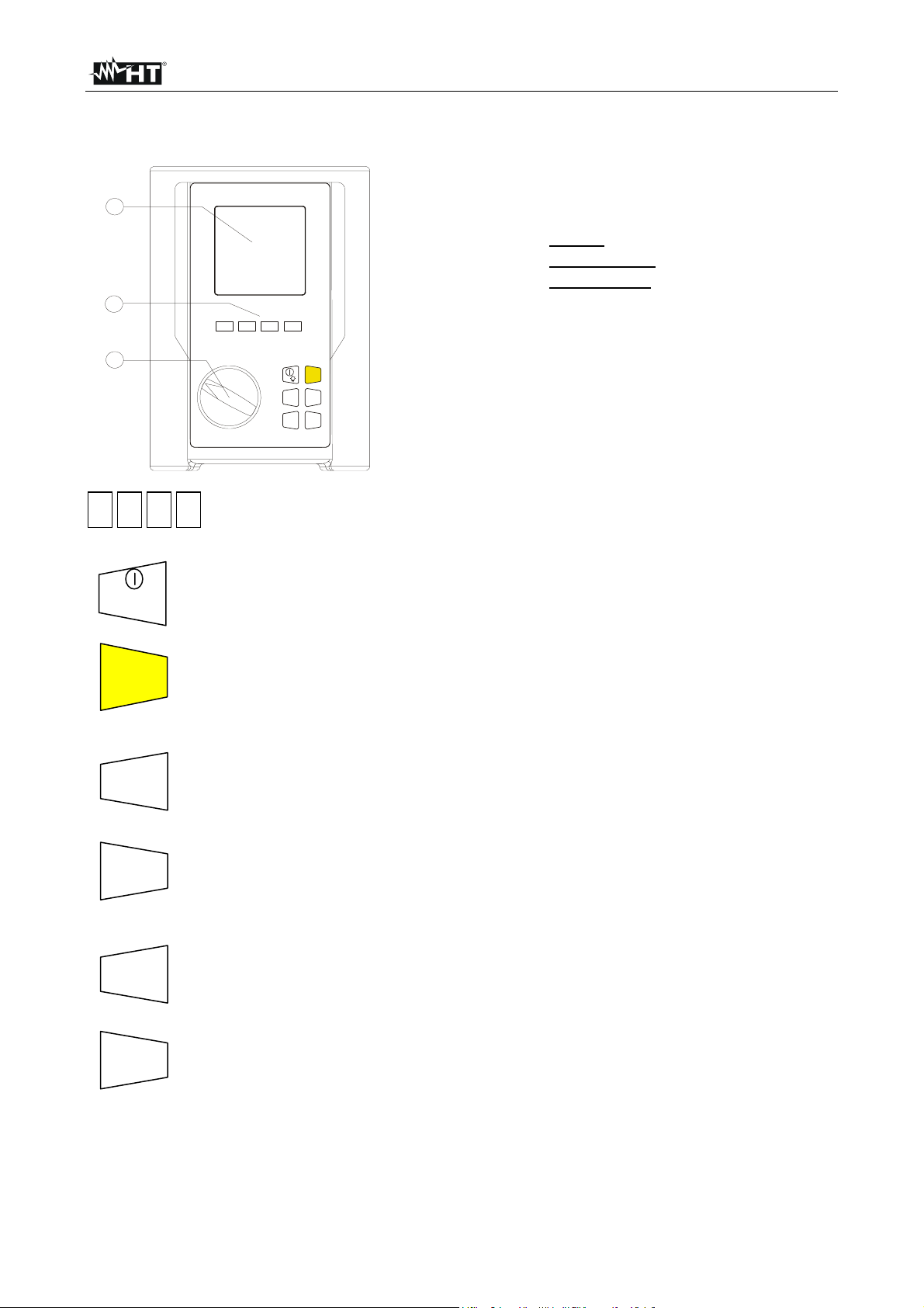
LEGEND:
1
2
F1 F3F4F2
1.
Display
2.
Function Keys
3.
Rotary switch
3
F1
ON
START
STOP
SAVE
HOLD
ENTER
MENU
F2 F4 F3
/
OFF
ESC
START
STOP
HOLD
SAVE
ENTER
MENU ESC
Multifunction Keys.
ON/OFF and backlight key. Press it for few seconds to switch OFF the
instrument, press it briefly to activate the backlight function.
This key start (and stop). the measurement.
This key allows to save the result displayed.
This key has a double function: it is the confirmation key inside the
configuration menu and it allows to freeze the displayed results using the
ANALYZER function.
This key open the General Configuration Menu.
This key quit the .modification in the configuration menu or the selected
working mode.
EN - 9
Page 12
SIRIUS89N
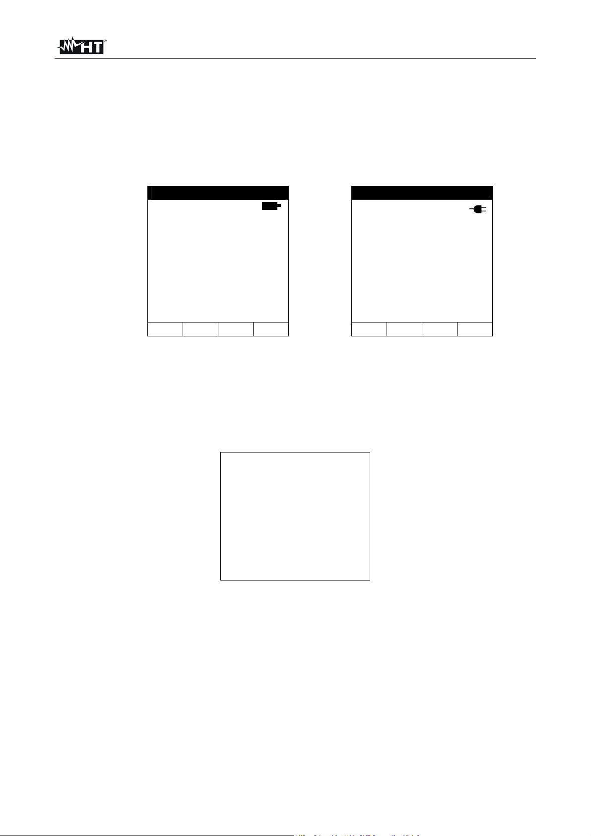
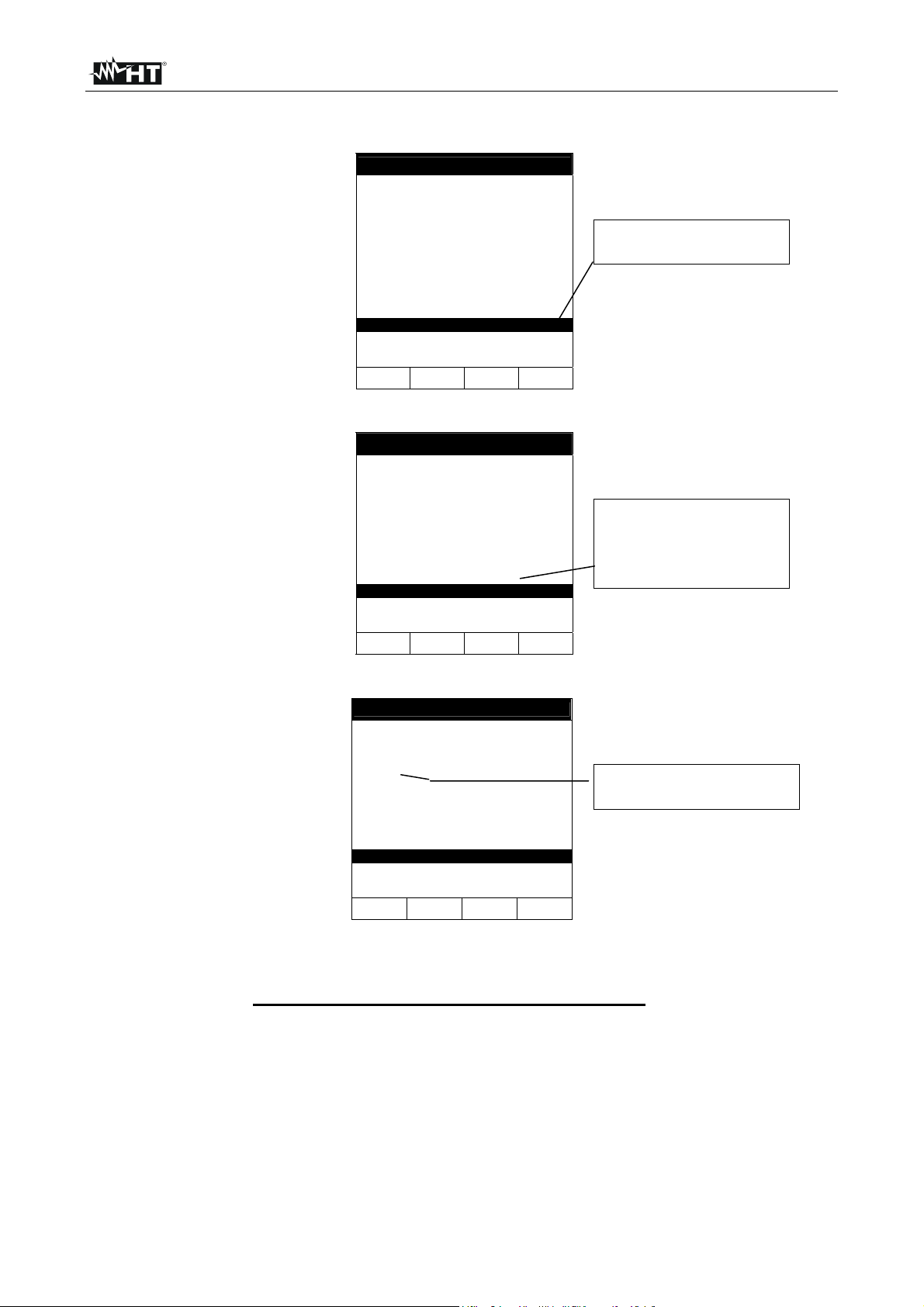
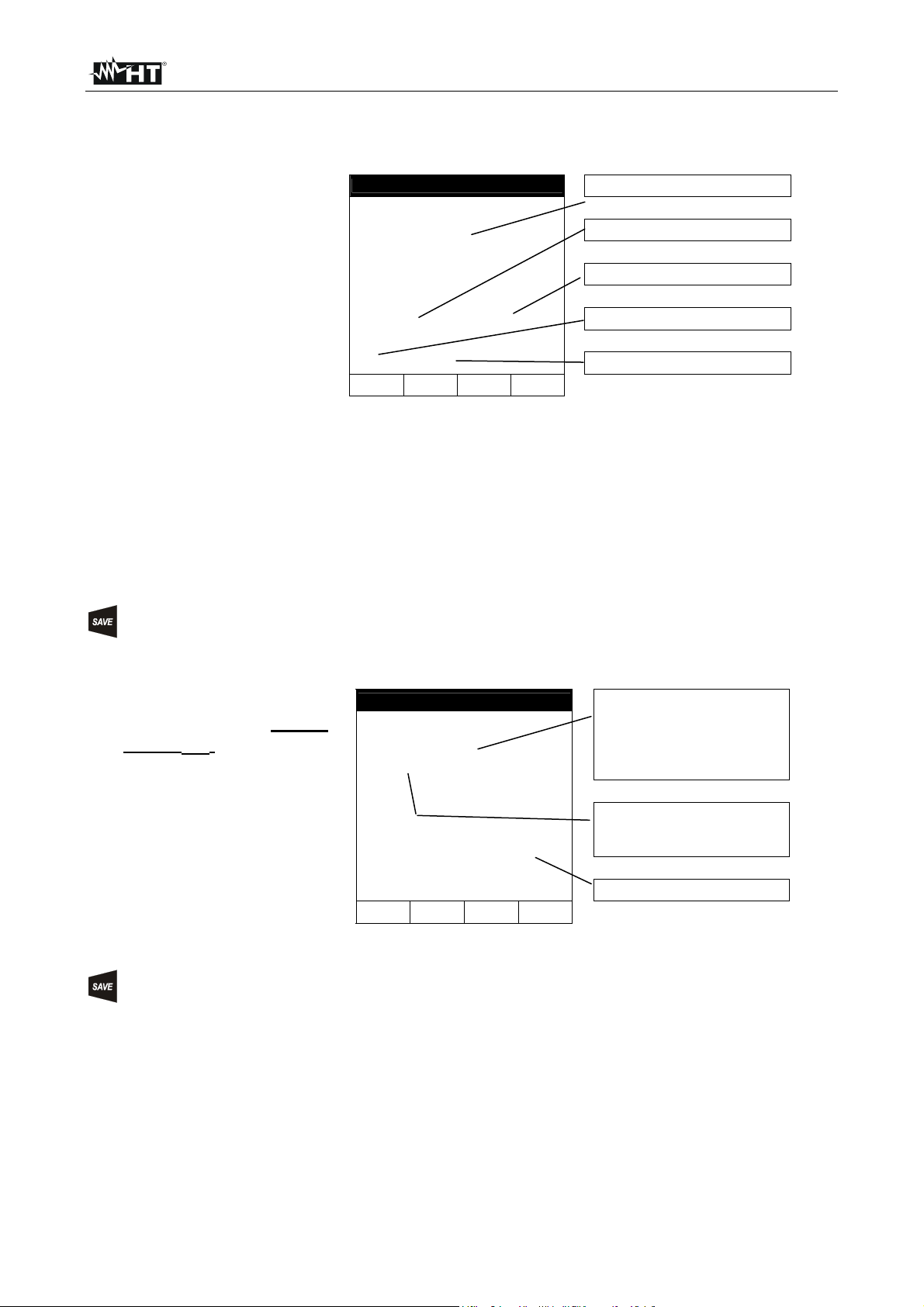
4.1. DISPLAY DESCRIPTION
The display is a graphic module with a resolution of128 x 128 pixels.
The first line of the display shows date and time. If not correct, you can set the exact ones
according to the procedure described at paragraph 5.2.
On the top right corner of the display you can always see the battery indicator and, if the
external power supply adapter (optional code A0050) is connected, the corresponding
symbol.
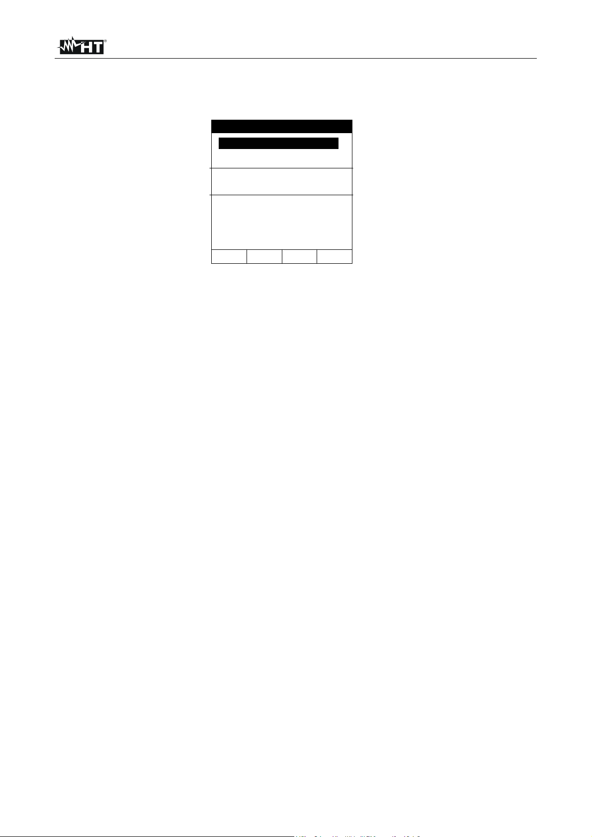
LOWΩ 05.06.01
R+ R-
----Ω ----Ω
---mA ---mA
AUTO 0.11Ω
----Ω
FUNC CAL
27.09.00 17:35:12
SINGLE PHASE
V1 = 230.2 V
Vpk1 = 325.5 V
ThdV = 0.0 %
freq = 50.0 Hz
HARM WAVE
VOLTAGE
These symbols will be omitted in the following illustrations.
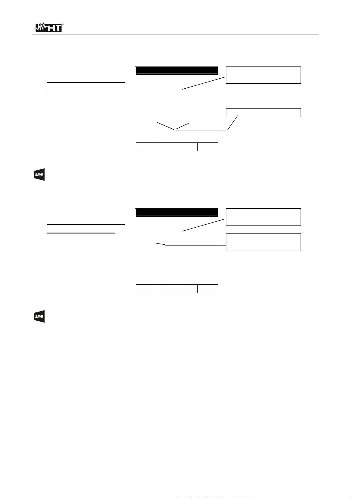
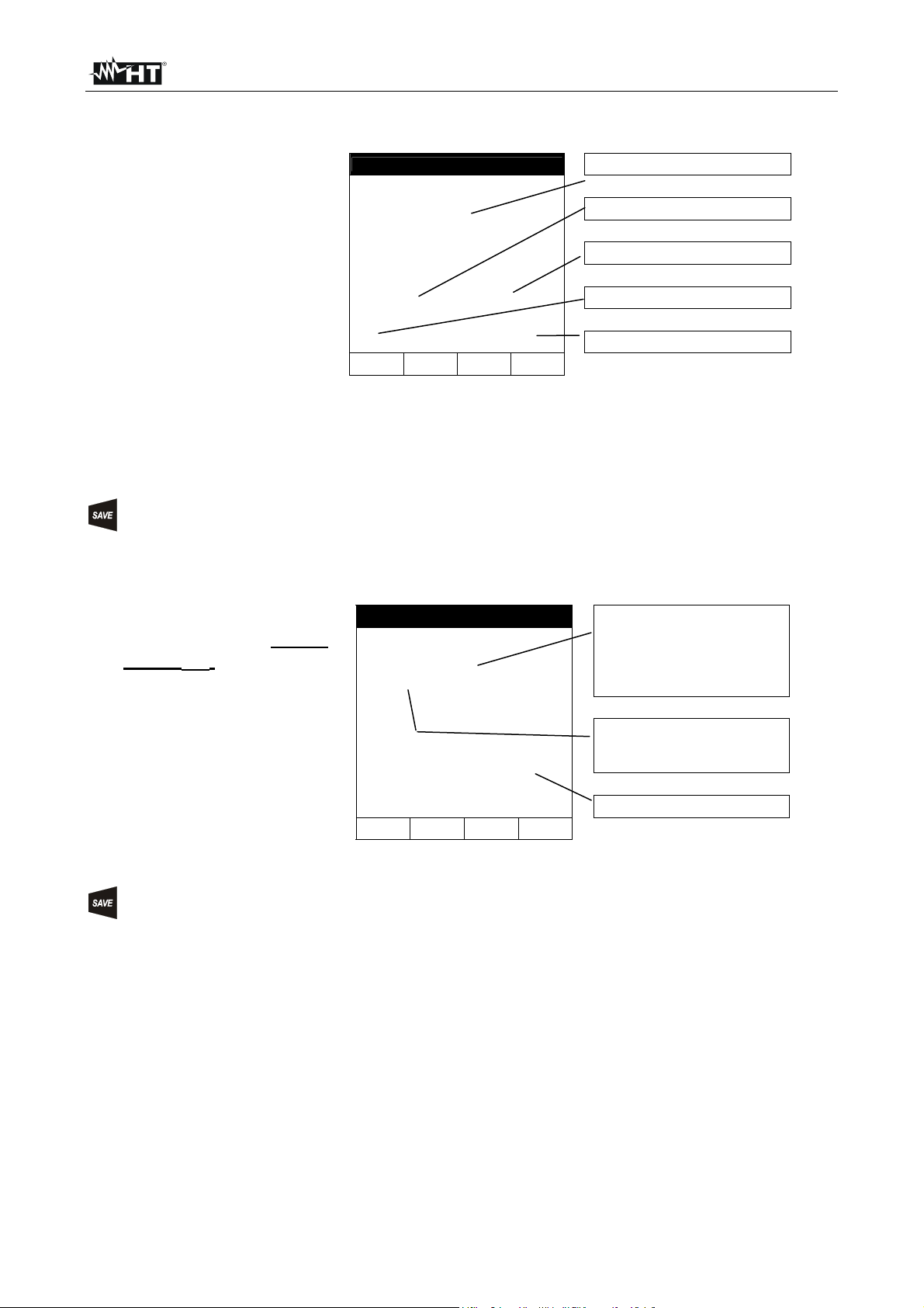
4.2. INITIAL SCREEN
When turning on the instrument by pressing ON/OFF, this screen will appear for a few
seconds:
SIRIUS89N
HT ITALIA
SN:00000000 V: X.XX
BAUD RATE 57600
CALIBRATION DATE
Here you can see:
• serial number of the instrument (SN.:)
• firmware software release (V.X.XX:)
• transmission speed through serial RS232 (Baud Rate)
• calibration date (CALIBRATION:)
4.3. BACKLIGHT FUNCTION
01.01.02
When instrument is turned on, pressing briefly the ON button, the backlight will be
enabled. The light will be automatically turned off after 5 seconds.
If the batteries are too low the instrument will disable automatically the backlight function.
EN - 10
Page 13
SIRIUS89N
5. INITIAL SETTINGS
By pressing the MENU key the following screen will be displayed:
MENU GENERAL
SAFETY TEST MEMORY
ANALYZER MEMORY
RESET
ANALYZER CONFIG
RECORDER CONFIG
CONTRAST
DATE&TIME
LANGUAGE
↓ ↑
It’s not possible to enter the MENU during a recording or a Real Time Energy
measurement. Pressing this button during a recording the display will show main recording
parameter (see paragraph 10.3).
5.1. HOW TO ADJUST THE CONTRAST
By pressing the multifunction keys F1 and F2, position the cursor on the CONTRAST item
and confirm it by pressing the ENTER key.
By pressing the multifunction keys F3 and F4, adjust the contrast (higher values
correspond to a higher contrast while lower values correspond to a lower contrast) and
press the ENTER key to SAVE the change or press ESC to quit the modification.
This setting will remain unchanged after turning off the instrument.
5.2. HOW TO SET DATE AND TIME
By pressing the multifunction keys F1 and F2, position the cursor on the DATE&TIME item
and confirm it by pressing the ENTER key.
The time is expressed as hh:mm (2 digit for hours, 2 digit for minutes) military time.
Press the ENTER key to SAVE the change or press ESC to quit the modification.
This setting will remain unchanged also after turning off the instrument.
5.3. HOW TO SET THE LANGUAGE
By pressing the multifunction keys F1 and F2, position the cursor on the LANGUAGE (EN)
or LINGUA (IT) item and confirm it by pressing the ENTER key.
By pressing the multifunction keys F1 and F2, position the cursor on the desired language
and press the ENTER key to SAVE the change or press ESC to quit the modification.
This setting will remain unchanged after turning off the instrument.
EN - 11
Page 14

SIRIUS89N
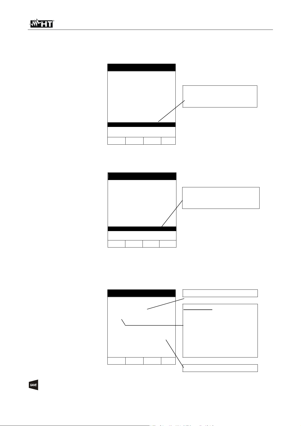
5.4. RESET
This option re-establishes the initial settings of the instrument in ANALYZER function.
The “Current Range” parameter it is not modified by Reset command
The initial settings of the instrument consist of:
ANALYZER CONFIG:
System: SINGLE
Frequency: not modified
Current range: not modified
Clamp type: not modified
Transforming ratio of voltmetric transformers: 1
Password: OFF
RECORDER CONFIG:
Start: MANU (the recording starts at
00 sec mark on clock after
pressing the START/STOP key)
Stop: MAN
Integration period: 15min
Recording of harmonics: ON
Recording of Voltage anomalies (Sag and Surge: ON
Voltage Reference for Sag and Surge detection: 230V
Upper Limit for Sag and Surge detection: 6%
Lower Limit for Sag and Surge detection: 10%
Selected voltages: V1
Selected voltage harmonics: THD, 01, 03, 05, 07
Selected currents: I1
Selected current harmonics: THD, 01, 03, 05, 07
CO-GENERATION: OFF
Powers, Pf and cosϕ selected: P1
Q1i
Q1c
S1
Pf1
DPf1
Energie: Ea1
Eri1
Erc1
The RESET command will not
erase the instrument’s memory.
EN - 12
Page 15

SIRIUS89N
6. SAFETY TEST FUNCTIONS
6.1. LOWΩ: CONTINUITY TEST WITH 200mA TEST CURRENT
The measurement is effected according to EN 61557-2 and VDE 0413 part 4.
Before carrying out the continuity test make sure that there is no voltage at
the ends of the conductor under test.
Turn the switch on LOWΩ position.
This key permits to select one of the following measuring modes:
Mode "AUTO" (the instrument carries out two measurements with
reversed polarity and displays their average value). This mode is
recommended for the continuity test.
Mode "RT+" (measurement with positive polarity and possibility of setting
the duration time of the test). In this case the operator can set a
measuring time long enough to permit him to move the protective
conductors while the instrument is carrying out the test so detecting any
bad connection.
Mode "RT-" (measurement with negative polarity and possibility of setting
the duration time of the test). In this case the operator can set a
measuring time long enough to permit him to move the protective
conductors while the instrument is carrying out the test so detecting any
bad connection.
This key permits to execute the "CAL" mode (compensation of the resistance
of the cables used for the measurement).
CAUTION
CAUTION
If the resistance is lower than 5Ω (including the resistance of the calibration)
the continuity test is executed by the instrument with a test current higher
than 200mA. If the resistance is higher than 5Ω the continuity test is
executed by the instrument with a current lower than 200mA.
We recommend you to check the Calibration of the test leads before executing a
measurement according to next paragraph.
EN - 13
Page 16
SIRIUS89N
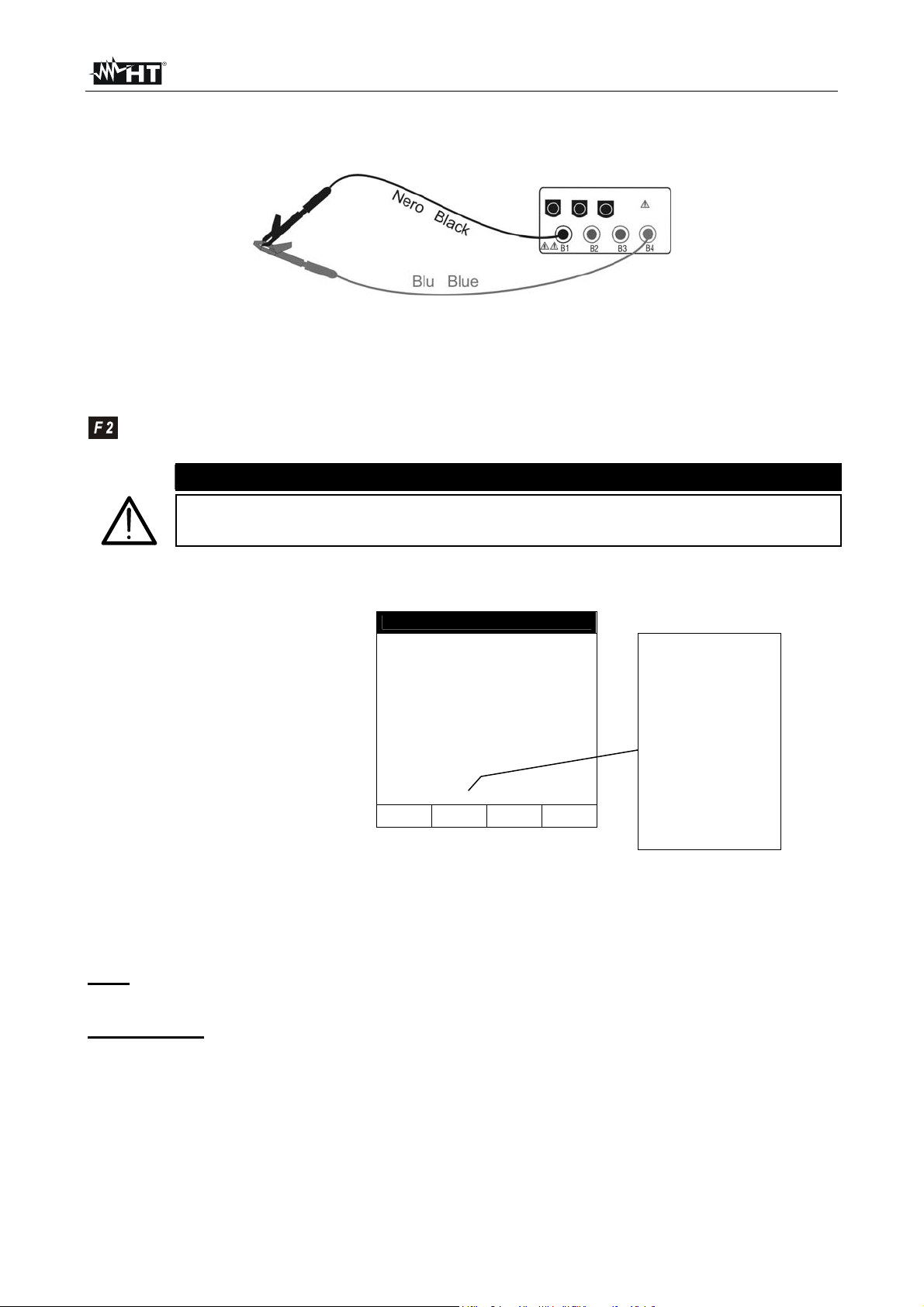
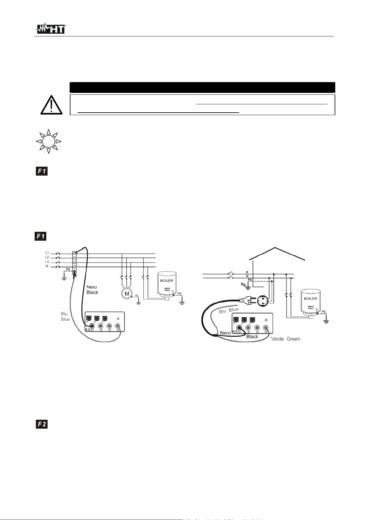
6.1.1. Calibrating the test leads ("CAL" Mode)
1. Connect the black and blue test leads to B1 and B4 input terminals
respectively.
Connection of instrument terminals during calibration procedure.
2. If the test leads supplied with the instrument are not long enough for the
measurement you can extend the blue cable.
3. Short-cir c u i t the measuring cable ends making sure that the conductiv e parts of the
crocodiles make a good contact to each other (see previous picture).
4. Press the F2 key. The instrument carries out the calibration.
CAUTION
Never disconnect the test leads when the message "MEASURING" is
displayed.
LOWΩ 05.06.01
----Ω
R+ R-
----Ω ----Ω
---mA ---mA
AUTO 0.11Ω
FUNC CAL
A numerical value
in this field means
that the instrument
has been
calibrated; this
value remains on
the display for
any further
measurement
even though the
unit is switched off
and on again
5. At the end of the test the result is stored and used as OFFSET (that is to say
that it is subtracted from any continuity test carried out) for all the
subsequent measurements.
Note: The instrument effects the calibration only if the resistance of the test leads is
lower than 5Ω.
TEST LEADS Before each measurement always make sure that
the calibration is referred to the cables in use.
During a continuity test, if the resistance value free
of calibration (that is the resistance value less the
calibration offset value) is negative, the symbols
o is displayed. Probably the calibration resistance
value stored in the instrument memory is not
referred to the cable in use, therefore a new
calibration must be effected.
EN - 14
Page 17
SIRIUS89N
6.1.1.1. Procedure to reset test leads calibration parameters
To cancel calibration
parameters it is
necessary to effect a
calibration procedure
with a resistance of
test leads higher than
5Ω (for example with
open test leads). When
a cancellation is effected
the screen nearby is
displayed first, followed
LOWΩ 05.06.01
o
>
99.9
R+ R-
----Ω ----Ω
---mA ---mA
AUTO 0.11Ω
FUNC CAL
Ω
Message >99.9Ω:
means that the
instrument detected a
resistance higher
than 5Ω therefore it
will proceed with
Reset procedure.
by the screen below:
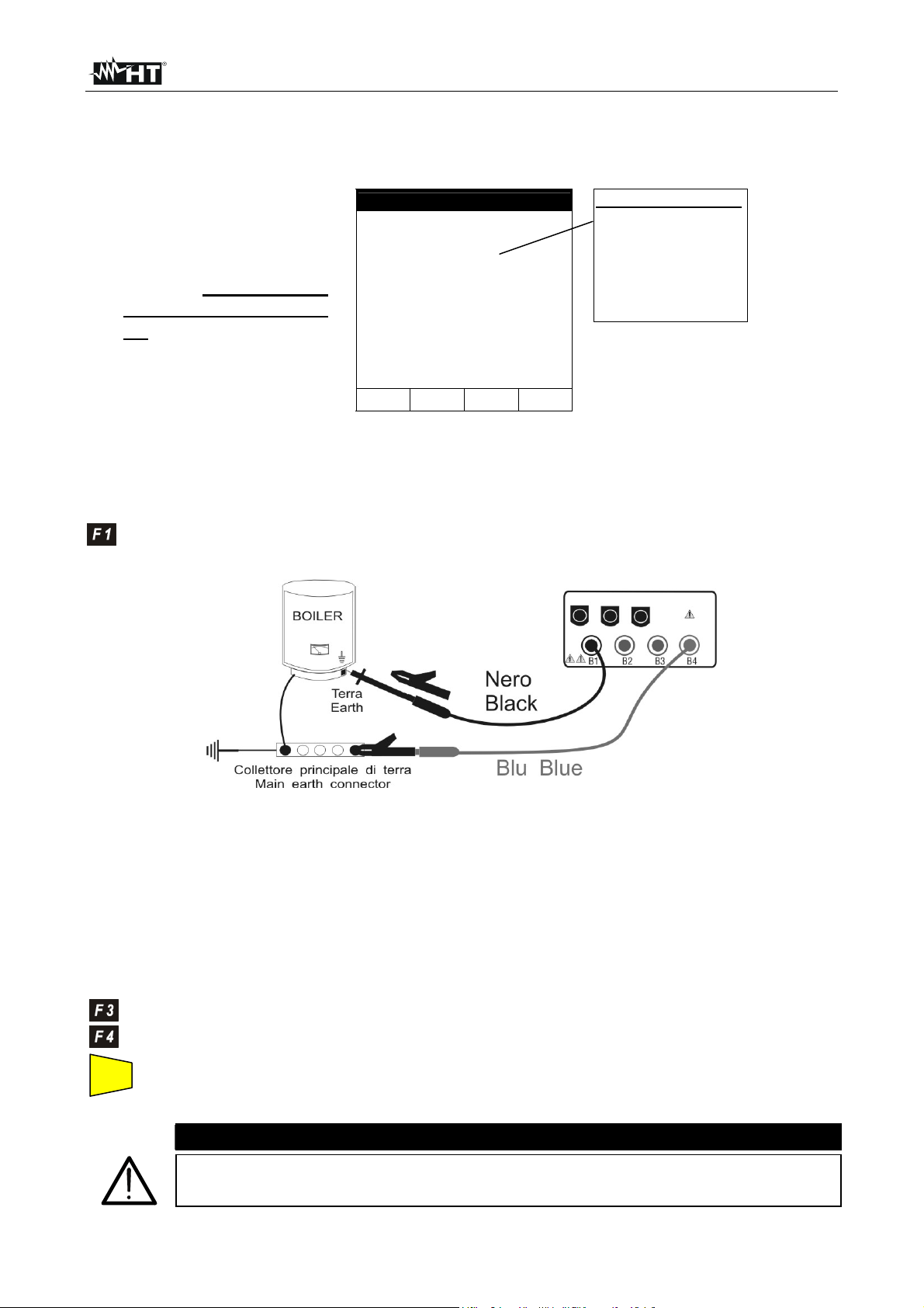
6.1.2. Measurement Procedure
1. Select the desired mode by means of the F1 key.
2. Connect the black and blue test leads to B1 and B4 input terminals respectively
Connection of the test leads during LOWΩ test.
3. If the cables supplied with the instrument are not long enough for the
measurement you can extend the blue cable.
4. Short-circuit the test leads making sure that the conductive parts of the
crocodiles make a good contact to each other. Press the START key. If the
displays doesn't show 0.00Ω repeat the test leads calibration (see
paragraph 6.1.1).
5. Connect the instrument terminals to the ends of the conductor under test (see
previous picture).
6. If the mode "RT+" or "RT-" was selected use the F3, F4 keys to set the
duration of the test.
START
STOP
7. Press the START key. The instrument will execute the measurement. In
RT+/RT- (Timer mode) you can press START key again if you want to stop the
test before the duration set is expired.
Never disconnect the test leads when the message "MEASURING" is
displayed.
CAUTION
EN - 15
Page 18
SIRIUS89N
A
A
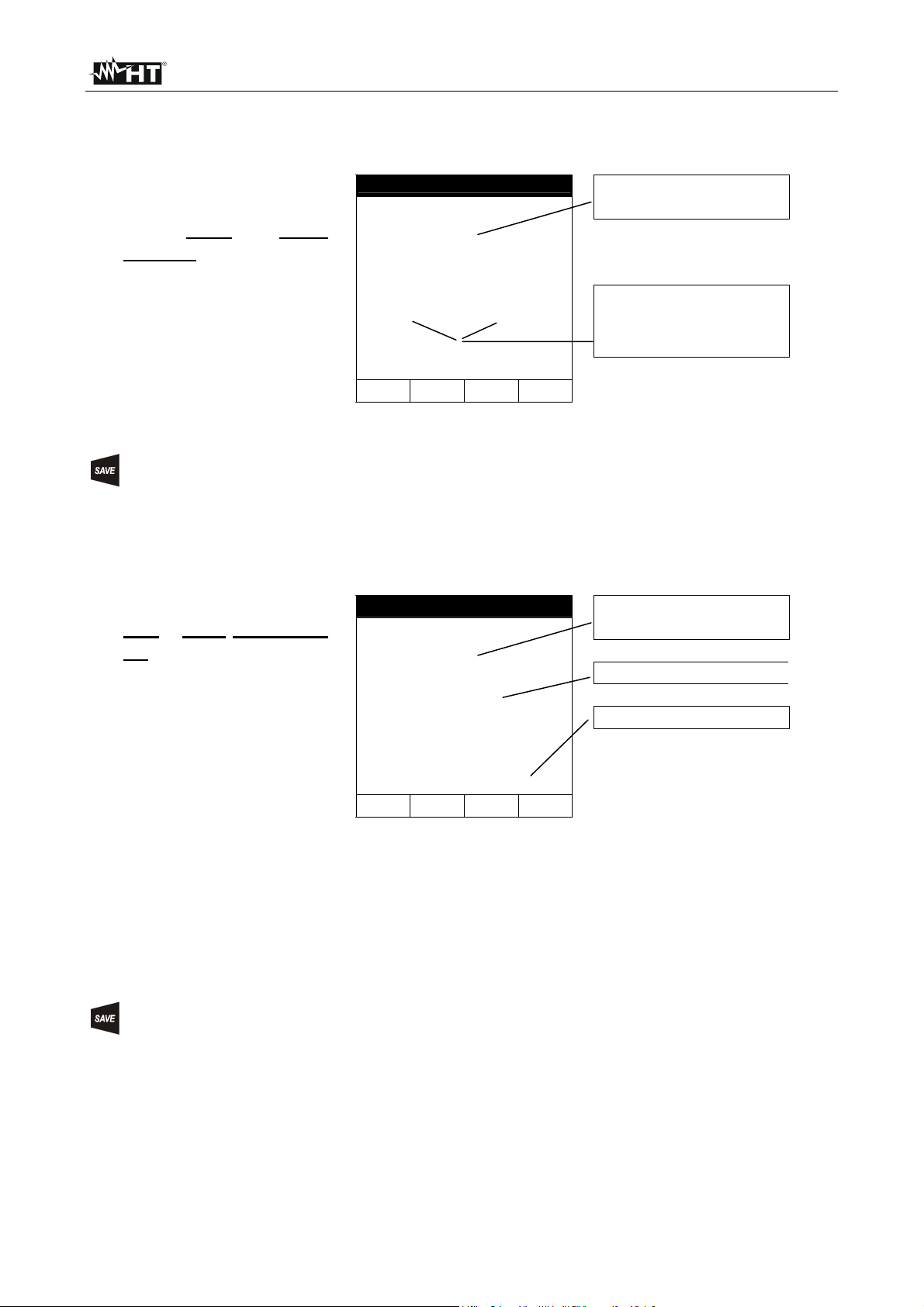
6.1.3. Results of "AUTO" mode
t the end of the test, if
the average resistance
value Ravg is lower
than 5Ω the instrument
emits a double sound
signal indicating the
positive outcome of
the test and displays
one screen similar to the
screen alongside.
LOWΩ 05.06.01
1.05Ω
R+ R-
1.07Ω 1.03Ω
219mA 219mA
AUTO 0.11Ω
FUNC CAL
verage resistance value
(Ravg)
Resistance values and
corresponding test current
got exchanging the
polarities of test leads
The displayed result can be stored pressing the SAVE key twice (according to
paragraph 9.1).
6.1.4. Results of "RT+" and "RT-" modes
if a resistance value
RT+ or RT+ lower than
5Ω is detected, the
instrument emits a
double sound signal
indicating the positive
outcome of the test
displays one screen
similar to the screen
alongside.
LOWΩ 05.06.01
1.07Ω
219mA
RT+ 0.11Ω TIME: 10s
FUNC CAL
↑ ↓
Max Resistance value of
R+ or R-.
Test current
Duration of the Test
Note: We recommend to use crocodiles and to check if the crocodiles make a good
contact with the conductor under test. Indeed in this test the instrument gives as
final result the maximum measured value of R+ or R- and suing test leads
instead of crocodiles could give you faulty result due to faulty contact between
the test leads and conductor under test
The displayed result can be stored pressing the SAVE key twice (according to
paragraph 9.1).
EN - 16
Page 19
SIRIUS89N
6.1.5. "AUTO", RT+", "RT-" faulty cases
If the instrument detect
the External Power
supply adapter
connected to instrument
will show the message
displayed to side.
LOWΩ 05.06.01
-.- -Ω
R+ R-
---Ω ---Ω
---mA ---mA
o REMOVE POWER
AUTO 0.11Ω!
FUNC CAL
Disconnect the External
Power Supply Adapter
If the terminal voltage is
higher than 15V, the
instrument does not
carry out the test and
displays the screen
alongside for 5 seconds.
LOWΩ 05.06.01
R+ R-
-.--Ω -.--Ω
---mA ---mA
AUTO 0.11Ω
FUNC CAL
-.- -Ω
o VOLT IN INPUT
ATTENTION: the test was
not effected because of
voltage at the terminal
ends.
In case that:
R
CALIBRATION>RMEASURED
the instrument displays
the screen alongside.
LOWΩ 05.06.01
o 0.00Ω
R+ R-
0.00Ω 0.00Ω
219mA 219mA
AUTO 0.11Ω
FUNC CAL
CAL > RES
ATTENTION:
R
CALIBRATION >RMEASURED
THE PREVIOUS RESULTS CAN'T BE SAVED.
EN - 17
Page 20
SIRIUS89N
If the value of
Resistance is higher
than 5Ω (but lower than
99.9Ω) the instrument
emits a long sound
signal and displays one
screen similar to the
screen alongside
LOWΩ 05.06.01
o 5.17Ω
R+ R-
5.17Ω 5.17Ω
209mA 209mA
AUTO 0.11Ω
FUNC CAL
Resistance value higher
than 5Ω
Test current
The displayed result can be stored pressing the SAVE key twice (according to
paragraph 9.1).
If the value of
Resistance is higher
than 99.9Ω the
instrument emits a long
sound signal and
displays the screen
alongside.
LOWΩ 05.06.01
o> 99.9Ω
R+ R-
-.--Ω -.--Ω
---mA ---mA
AUTO 0.11Ω
FUNC CAL
Resistance value higher
than 99.9Ω
ATTENTION: Value of
Resistance Out of Range
The displayed result can be stored pressing the SAVE key twice (according to
paragraph 9.1).
EN - 18
Page 21
SIRIUS89N
6.2. MΩ: INSULATION RESISTANCE MEASUREMENT WITH 50V, 100V, 250V,
500V, 1000V TEST VOLTAGE
The measurement comply with IEC 61557-2 and VDE 0413 part 1.
CAUTION
Before effecting the insulation test make sure that the circuit under test is
not energised and all the loads are disconnected.
Turn the switch on MΩ position.
The key F1 permits to select one of the following measuring modes:
Mode "MAN" (Manual mode). Recommended test.
Mode "TMR" (Timer mode: test duration depends on the selected interval
from 10 to 999 seconds). This test can be executed when the test
required a defined duration.
6.2.1. Measurement Procedure
1. Select the desired mode by means of the F1 key.
2. Connect the test leads to the instrument input terminals B1 and B4 respectively,
Example: insulation measurement between phase and
earth in an electrical installation using untied cables.
3. If the cables supplied with the inst rument are not long enough for the measurement
you can extend the blue cable.
4. Connect the instrument terminals to the object which is to be submitted to the
insulation test after de-energizing the circuit under test and all the relative
loads (see previous picture).
5. B y means of F2 select the test voltage suitable for the type of test to be carried
out (see Table1). The values to be selected are:
• 50V (test on telecommunication systems)
• 100V
• 250V
• 500V
• 1000V
EN - 19
Example: insulation measurement between
phase and earth in an electrical installation
using the shuko cable.
Page 22
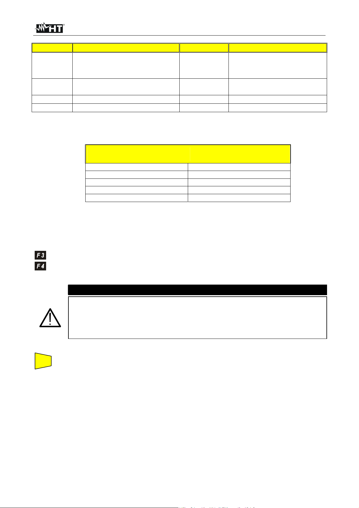
SIRIUS89N
Standard Brief description Test voltage Maximum limit value
> 0.250MΩ
> 0.500MΩ
> 1.0MΩ
> 50kΩ (se V<500V)
> 100kΩ (se V>500V)
> 230kΩ
> 1MΩ
CEI 64-8/6
CEI 64-8/4
Floor and wall insulation in civil installation s
Floor and wall insulation in systems over 500V
Systems SELV or PELV
Systems up to 500V (Civil installations)
Systems over 500V
250VDC
500VDC
1000VDC
500VDC
1000VDC
EN60439 Electrical panel boards 230/400V 500VDC
EN60204 Electrical equipment of machines 500VDC
Table1: Table reporting the test voltage and the corresponding limit values for
few Guidelines.
Rated voltage selected
for the test
50VDC
100VDC
250VDC
500VDC
1000VDC
R
= Maximum resistance
MAX
value
99.9MΩ
199.9MΩ
499MΩ
999MΩ
1999MΩ
Table2: Table of maximum resistance values which can be measured under MΩ
mode depending on the rated voltage selected.
6. If the "TMR" mode was selected use the F3, F4 keys to set the duration time of
the test:
CAUTION
Never disconnect the test leads from the circuit under test when the
message "MEASURING" is displayed as the circuit under test may remain
charged at a dangerous voltage. The instrument has an internal "safety
resistor" which is connect to output terminal before end of test in order to
discharge the parasite capacities of the installation
START
STOP
7. Press the START key.
The instrument will start the test.
MAN Mode: The test will take 4 seconds (maximum). If you kee p
the START key pressed longer than 4 seconds the test go on
until the key is released.
TMR mode: The test will take the time set. If you want to stop
the test when it's running, press the START STOP key again.
EN - 20
Page 23
SIRIUS89N
A
6.2.2. Results of "MAN" mode
t the end of the test if
the Insulation
resistance is lower
than R
and the instrument
generated the
Nominal test Voltage,
the instrument emits a
double sound signal
indicating the positive
outcome of the test
(see Table2)
MAX
MΩ 05.06.01
1.07
514V 15s
MAN 500V
FUNC VNOM
MΩ
Insulation Resistance
Voltage during the Test
Duration of the Test
Test mode
Test voltage set
and displays one
screen similar to the
screen alongside.
In order to evaluate the test you must compare the result with the limits indicated in the
Guidelines (see Table1).
The displayed result can be stored pressing the SAVE key twice (according to
paragraph 9.1).
If the Insulation
resistance is higher
than R
the instrument emits a
double sound signal at
the end of the test
indicating the positive
(see Table2),
MAX
outcome of the test
and displays one screen
similar to the screen
alongside.
MΩ 05.06.01
> 999
523V 15s
MAN 500V
FUNC VNOM
M
Ω
Maximum resistance value
which can be measured
(999Ω is displayed if a
rated voltage of 500V was
selected see Table2).
The symbol ">" means that
the resistance value is
higher than R
MAX
.
Test duration
The displayed result can be stored pressing the SAVE key twice (according to
paragraph 9.1).
EN - 21
Page 24
SIRIUS89N
A
6.2.3. Results of "TMR" mode
t the end of the test if
the Insulation
resistance is lower
than R
and the instrument
generated the
Nominal test Voltage,
the instrument emits a
double sound signal
indicating the positive
outcome of the test
(see Table2)
MAX
MΩ 05.06.01
1.07
514V 15s
TMR 500V TIME:60s
FUNC VNOM
M
↑ ↓
Ω
Insulation Resistance
Voltage during the Test
Duration of the Test
Test mode
Setting Time
and displays one
screen similar to the
screen alongside.
The displayed result can be stored pressing the SAVE key twice (according to
paragraph 9.1).
If the Insulation
resistance is higher
than R
the instrument emits a
double sound signal at
the end of the test
indicating the positive
(see Table2),
MAX
outcome of the test
and displays one screen
similar to the screen
alongside.
MΩ 05.06.01
> 999
523V 15s
TMR 500V TIME:60s
FUNC VNOM
M
Ω
↑ ↓
Maximum resistance value
which can be measured
(999Ω is displayed if a
rated voltage of 500V was
selected see Table2).
The symbol ">" means that
the resistance value is
higher than R
MAX
.
Test duration
The displayed result can be stored pressing the SAVE key twice (according to
paragraph 9.1).
EN - 22
Page 25
SIRIUS89N
6.2.4. "MAN" and "TIMER" mode faulty cases
If the instrument
detect the External
Power supply adapter
connected to
instrument will show
the message
displayed to side.
MΩ 05.06.01
-.- -
---V 15s
o REMOVE POWER
MAN 500V!
FUNC VNOM
M
Ω
Disconnect the External Power
Supply Adapter
If the instrument
detect a Voltage
between Input
terminals higher than
15V, the instrument
does not effect the
test and displays the
screen alongside for 5
seconds.
MΩ 05.06.01
-.- -
---V 15s
o VOLT IN INPUT
MAN 500V
FUNC VNOM
M
Ω
ATTENTION: the test can't be
executed. Check that the circuit is
not energised.
These result can't be saved
If the instrument can't
generate the Nominal
Test Voltage it will
emits a long
acoustic signal and
displays a screen
similar to the screen
alongside.
MΩ 05.06.01
o 1.17
107V 15s
MAN 500V
FUNC VNOM
M
Ω
Insulation Resistance
ATTENTION: the test of
resistance R
a voltage value lower than the
set rated voltage. Low
insulation case. This case
occurs under low insulation
conditions or in the presence of
capacity on the installation.
ISO
Test Time
was effected at
The displayed result can be stored pressing the SAVE key twice (according to
paragraph 9.1).
EN - 23
Page 26
SIRIUS89N
6.3. RCD: TEST ON "A" AND "AC" RCDS TYPE
The test is executed according to IEC61557-6, EN61008, EN61009, EN60947-2 B 4.2.4
and VDE 0413 part 6.
CAUTION
The automatic check of the RCD features causes the tripping of the RCD itself.
Therefore check that all devices connected downstream the RCD under
test are not damaged by power off. Possibly disconnect all the loads
connected downstream the RCD as they could add additional leakage currents
to the instrument ones and so making the test results void.
Turn the switch on RCD position:
The F1 key permits to select one of the following measuring mode (which can
be shown cyclically when pressing the key):
Mode "AUTO" (the instrument effects the test automatically with a
leakage current equal to half, once and five times the value of the rated
current set). Recommended test.
Mode "x ½" (the instrument effects the test with a leakage current equal
to half the value of the rated current set).
Mode "x 1" (the instrument effects the test with a leakage current equal
to once the value of the rated current set ).
Mode "x 2" (the instrument effects the test with a leakage current equal
to twice the value of the rated current set).
Mode "x 5" (the instrument effects the test with a leakage current equal
to five times the value of the rated current)
Mode " " (the instrument effects the test with a ramp growing leakage
current. Use this test to measure the tripping current).
Mode "R
" (the instrument effects the test with a leakage current
A
equal to half the value of the selected rated current and calculates the
contact voltage as well as the Ra earth resistance).
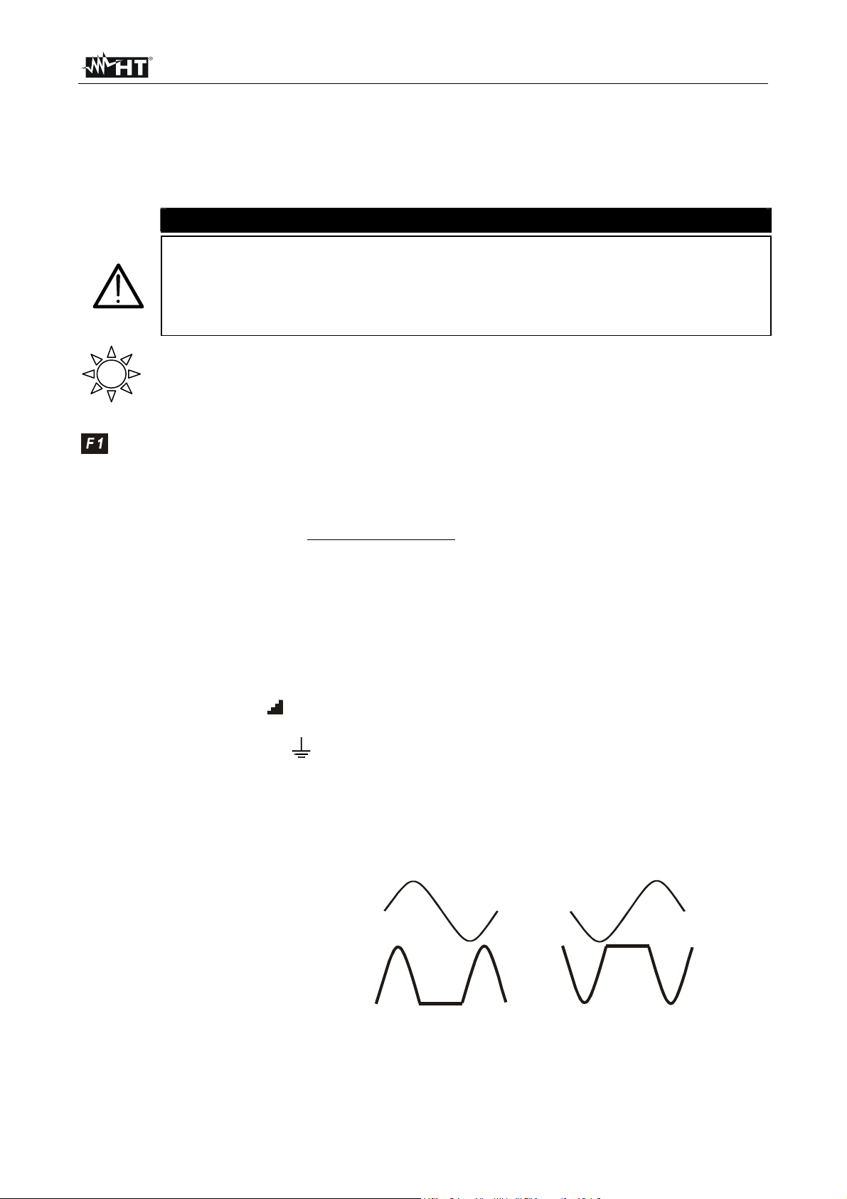
N.B. The AUTO mode execute automatically test with phase 0° and 180°
RCD Type 0° Current Waveform 180° Current Waveform
AC type
A type
According to standard praxis it is recommended to effect RCD test both with
phase 0° and with phase 180° even with no AUTO modes. If the RCD under
test is A type (which means sensitive to both AC and unidirectional pulsing
EN - 24
Page 27
SIRIUS89N
leakage currents) it is advisable to effect the test both with sine wave and
unidirectional pulse current with phase 0° and 180°.
The F2 key permits to select one of the following rated tripping currents of the
RCD (which can be shown cyclically when pressing the key):
10mA.
30mA.
100mA.
300mA.
500mA.
The F3 key permits to select the RCD type (which can be shown cyclically
when pressing the key):
"b": general RCD AC type (sensitive to sine leakage current)
"l": general RCD A type (sensitive to pulsating leakage current)
"
bn
": selective RCD AC type (sensitive to sine leakage current)
"
ln
": selective RCD A type (sensitive to pulsating leakage current)
Note if the test is effected on general RCDs the symbol n is NOT displayed
Note according to EN61008 the test on the selective RCDs requires an interval between
the tests of 60 seconds (30 seconds in case of tests at ½ I∆n). A timer is displayed
indicating the waiting time for each step.
Example: Test with AUTO mode on a RCD with I∆n=30mA.
a) the instrument effects the test at ½ I∆n 0°. The RCD must not
trip.
b) The instrument effects the test at ½ I∆n 180°. The RCD must
not trip. For a Selective RCD a 30 seconds timer starts
before executing next test.
c) The instrument effects the test at I∆n 0°. If the RCD passed
the test, it must trip and the instrument shows the message
"RESUME RCD". The operator shall resume the RCD. For a
Selective RCD a 60 seconds timer starts before executing
next test.
d) The instrument effects the test at I∆n 180°. Follow the same
procedure as described under c).
e) The instrument effects the test at 5I∆n 0°. Follow the same
procedure as described under c).
f) The instrument effects the test at 5I∆n 180°. Follow the same
procedure as described under c). The test is completed.
The F4 key permits to select one of the following limit values for the
contact voltage (which can be shown cyclically when pressing the key):
50V (default)
25V.
CAUTION
Never disconnect the test leads when the message "MEASURING" is
displayed.
EN - 25
Page 28
SIRIUS89N
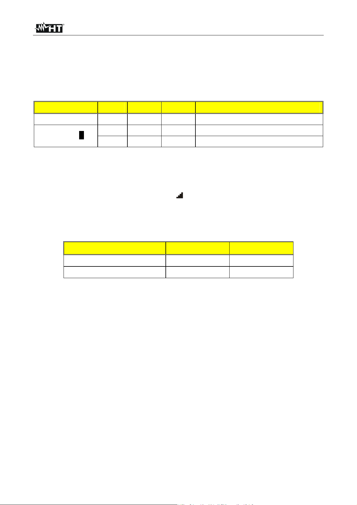
6.3.1. Tripping times for the general and selective RCDs
Table of tripping times for I
x1, I∆N x2, I∆N x5 and AUTO tests.
∆N
If the parameters set on the instrument comply with the type of RCD under test (and
if the latter works properly) the test x1, x2, x5 SHALL cause the RCD tripping within
the times shown in the following table:
RCD type
I
∆N
x 1 I
x 2 I
∆N
∆N
x 5
Description
General 0.3s 0.15s 0.04s Max tripping time in seconds
0.5s 0.20s 0.15s Max tripping time in seconds
Selective S
0.13s 0.05s 0.05s Minimum tripping time in seconds
* For rated values I∆N ≤ 30mA the test current at five times is 0.25A.
For currents equal to ½
Table 3: Table of tripping times for tests with leakage currents I
I
the RCD shall not trip in any case.
∆N
x1, I
∆N
x5 and AUTO.
Table of tripping times for ramp tests " ".
This test is not used to be effected to compare the RCD tripping time at the tripping
current, while the standards refer to the maximum tripping times in case the RCD is
checked with a leakage current equal to the rated current.
The limits value for the tripping current are indicated in the following Table:
RCD Type
A
AC
I
≤ 10mA
∆N
1,4 x I
I
1,4 x I∆N
∆N
I∆N
∆N
I
>
10mA
∆N
x2, I∆N
∆N
Table 4: Current limit value for "Ramp" Test
EN - 26
Page 29
SIRIUS89N
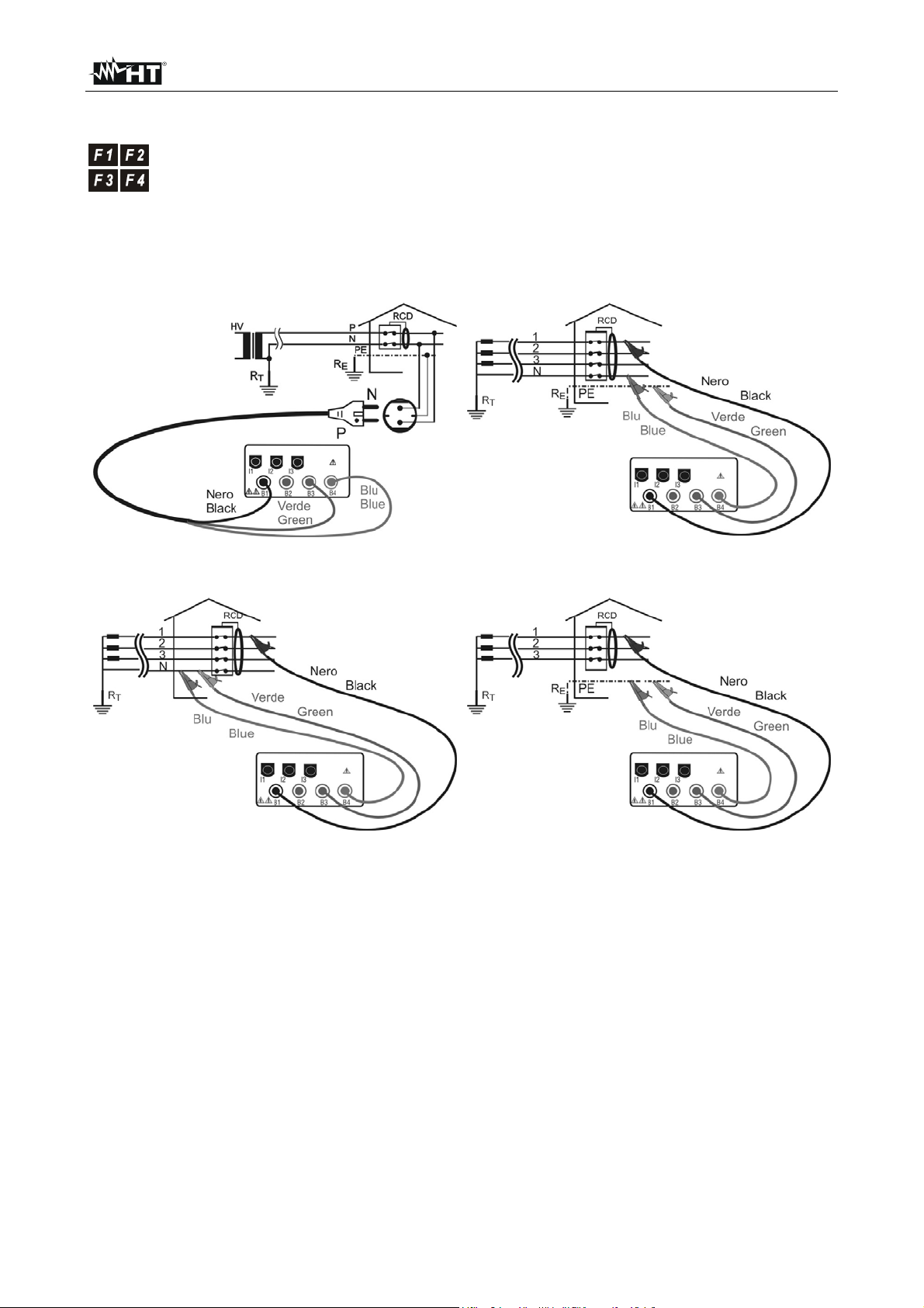
6.3.2. Measurement procedure
1. Select the desired test parameter by means of the F1, F2, F3, F4 key.
2. Connect the Black, Green and Blue connectors of the three-terminal shuko cable or
of the split cables to the corresponding input terminals of the instrument B1, B3, B4
Instrument connection for 230V single-phase
RCD check
Instrument connection for 400V + N (no PE) three-
phase RCD check
3. Connect the shuko plug or the Test leads to the System under test according
with one of the picture above.
Instrument connection for 400V + N + PE three-
phase RCD check
Instrument connection for 400V + PE (no N)
three-phase RCD check
EN - 27
Page 30
SIRIUS89N
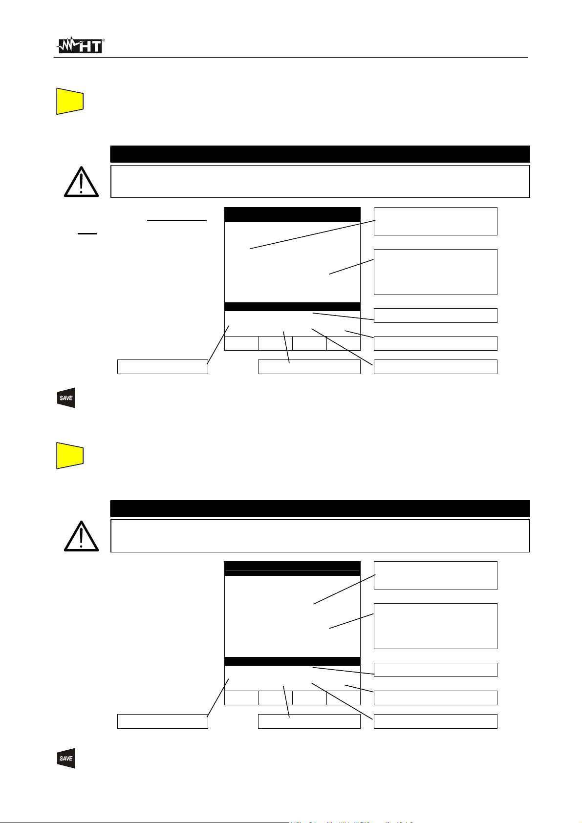
6.3.2.1. Results of "x½" mode
START
STOP
4. Press the START key once to execute a test with 0° Current waveform.
or
Press the START key once to execute a test with 180° Current waveform.
CAUTION
Never disconnect the test leads when the message "MEASURING" is
displayed.
If the RCD does NOT
trip the instrument emits
a double sound signal
indicating the positive
outcome of the test and
displays the screen
alongside.
Working mode
RCD 05.06.01
> 999
FRQ=50.0Hz Ut= 1V
VP-N=231V VP-PE=231V
x1/2 30mA 50V!
FUNC IdN RCD UL
RCD nominal current
ms
RCD OK
The symbol ">" means that
the RCD did not trip.
Value of contact voltage U
detected referred to the
rated value of the RCD
current set.
OK: RCD passed the test.
Contact Voltage Limit value
RCD type
t
The test can be stored pressing the SAVE key twice (according to paragraph 9.1).
6.3.2.2. Results of "x1, x2, x5" mode
STOP
4. Press the START key once to execute a test with 0° Current waveform.
START
or
Press the START key once to execute a test with 180° Current waveform.
CAUTION
Never disconnect the test leads when the message "MEASURING" is
displayed.
If the tripping time is
within the limits reported
in Table 3, the
instrument emits a
double sound signal
indicating the positive
outcome of the test and
displays the screen
alongside.
Working mode
RCD 05.06.01
49
FRQ=50.0Hz Ut= 2V
VP-N=231V VP-PE=231V
x1 30mA 50V!
FUNC IdN RCD UL
RCD nominal current
ms
RCD OK
Tripping time (expressed in
milliseconds).
Value of contact voltage U
detected referred to the
rated value of the RCD
current set.
OK: RCD passed the test.
Contact Voltage Limit value
RCD type
t
The test can be stored pressing the SAVE key twice (according to paragraph 9.1).
EN - 28
Page 31

SIRIUS89N
6.3.2.3. Results of "AUTO" mode
START
4. Press the START key once to execute the test. The instrument carries out the
STOP
following six tests with different values of rated current:
1/2I∆n with 0° current waveform (the RCD shall not trip).
1/2I∆n with 180° current waveform (the RCD shall not trip).
I∆n with 0° current waveform (the RCD trips, message "RESUME RCD").
I∆n with 180° current waveform (the RCD trips, message "RESUME RCD").
5I∆n with 0° current waveform (the RCD trips, message "RESUME RCD").
5I∆n with 180° current waveform (the RCD trips, end of the test).
The test is good if all values of tripping times are within the limits reported in
Table 3.
CAUTION
Never disconnect the test leads when the message "MEASURING" is
displayed.
At the end of the test if
all six tests resulted to
be positive, the
instrument displays the
screen alongside
relative to the last
measurement effected.
RCD 05.06.01
0° 180°
x1/2 >999ms >999ms
x1 55ms 65ms
x5 20ms 30ms
FRQ=50.0Hz Ut= 1V
VP-N=231V VP-PE=231V
AUTO 30mA 50V!
FUNC IdN RCD UL
RCD OK
Tripping time (expressed in
milliseconds).
Value of contact voltage U
detected referred to the
rated value of the RCD
current set.
OK: RCD passed the test.
t
Contact Voltage Limit value
Working mode
RCD nominal current
RCD type
The test can be stored pressing the SAVE key twice (according to paragraph 9.1).
EN - 29
Page 32

SIRIUS89N
A
6.3.2.4. Results of "RAMP " mode
START
4. Press the START key once to execute a test with 0° Current waveform.
STOP
or
Press the START key once to execute a test with 180° Current waveform.
The instrument generates a leakage current growing step by step for a given
time interval.
CAUTION
Never disconnect the test leads when the message "MEASURING" is
displayed.
t the end of the test if
the RCD tripping current
is lower than I∆n (Type
AC) or 1.4I∆n (Type A
with I∆n >10mA) or 2I∆n
(Type A with I∆n ≤10mA),
the instrument emits a
double sound signal
indicating the positive
outcome of the test and
displays the screen
alongside.
RCD 05.06.01
27
FRQ=50.0Hz Ut= 1V
VP-N=231V VP-PE=231V
30mA 50V!
FUNC IdN RCD UL
RCD OK
mA
35ms
Tripping Current
Tripping time (expressed in
milliseconds).
Value of contact voltage U
detected referred to the
rated value of the RCD
current set.
OK: RCD passed the test.
Contact Voltage Limit value
t
Working mode
RCD nominal current
RCD type
The test can be stored pressing the SAVE key twice (according to paragraph 9.1).
EN - 30
Page 33

SIRIUS89N
6.3.2.5. Results of " RA" mode
START
4. Press the START key once: the instrument carries out the test.
STOP
CAUTION
Never disconnect the test leads when the message "MEASURING" is
displayed.
The RCD must NOT
trip and the instrument
emits a double sound
signal indicating the
positive outcome of
the test and displays the
screen alongside.
RCD 05.06.01
12
FRQ=50.0Hz Ut= 1V
VP-N=231V VP-PE=231V
RA 30mA 50V!
FUNC
IdN
Ω
Ut OK
RCD UL
Global Earth Resistance
Value).
Value of contact voltage U
detected referred to the
rated value of the RCD
current set.
OK:Contact Voltage Not
Dangerous.
t
Contact Voltage Limit value
Working mode
RCD nominal current
RCD type
The test can be stored pressing the SAVE key twice (according to paragraph 9.1).
EN - 31
Page 34

SIRIUS89N
6.3.3. RCD Faulty cases
6.3.3.1. Connection troubles
If the instrument detect
the External Power
supply adapter
connected to instrument
will show the message
displayed to side.
RCD 05.06.01
- - -
FRQ=50.0Hz Ut= ---V
VP-N=230V Vp-PE=230V
o REMOVE POWER
x1 30mA 50V!
FUNC IdN RCD UL
ms
Disconnect the External
Power Supply Adapter
Should the instrument
detect that the phase
and/or neutral cables
are not connected to an
installation, screen
alongside is displayed
when pressing START.
RCD 05.06.01
- - -
FRQ=50.0Hz Ut= ---V
VP-N= 0V Vp-PE= 0V
o LOW VOLTAGE
x1 30mA 50V!
FUNC IdN RCD UL
ms
NO VOLTAGE Detected
Should the instrument
detect a voltage
between phase and
neutral higher of 250V,
for example in case the
blue cable is connected
to an installation phase
conductor of a 400V
three-phase system, the
screen alongside is
displayed.
RCD 05.06.01
- - -
FRQ=50.0Hz Ut= ---V
VP-N=401V VP-PE= 230V
o HIGH VOLTAGE
x1 30mA 50V!
FUNC IdN RCD UL
ms
HIGH VOLTAGE Detected
EN - 32
Page 35

SIRIUS89N
This screen is displayed
when the phase
conductor has been
exchanged with the
neutral one.
The instrument does not
effect the test. Reverse
the shuko plug or
exchange the black
cable with the blue one.
Repeat the test
RCD 05.06.01
- - -
FRQ=50.0Hz Ut= ---V
VP-N=231V VP-PE= 0V
o CHANGE P-N
x1 30mA 50V!
FUNC IdN RCD UL
ms
Phase and Neutral
Conductors are
exchanged.
This screen is displayed
when the phase
conductor has been
exchanged with the
Protection Conductors.
The instrument does not
effect the test. Reverse
the phase to earth
connection in the plug or
exchange the black
cable with the green one
RCD 05.06.01
- - -
FRQ=50.0Hz Ut= ---V
VP-N= 2V VP-PE= 230V
o CHANGE P-PE
x1 30mA 50V!
FUNC IdN RCD UL
ms
Phase and Protection
Conductors are
exchanged.
This screen is displayed
when in a 230V Phase
to Phase System the
blue conductor was
reversed with respect to
the green one.
The instrument does not
effect the test. Reverse
the blue and green
conductors.
RCD 05.06.01
- - -
FRQ=50.0Hz Ut= ---V
VP-N=130V VP-PE= 227V
o CHANGE N-PE
x1 30mA 50V!
FUNC IdN RCD UL
ms
Neutral and Protection
Conductors are
exchanged.
EN - 33
Page 36

SIRIUS89N
If a contact voltage U
higher than the
selected limit (U
detected, the instrument
interrupts the test and
emits a long sound
signal at the end of the
test and displays the
screen alongside.
) is
L
RCD 05.06.01
t
- - -
FRQ=50.0Hz Ut= ---V
VP-N=234V VP-PE= 234V
o UT DANGEROUS
x1 30mA 50V!
FUNC IdN RCD UL
ms
The instrument doesn't
detect an efficient
protection circuit.
If the instrument detects
that the earth cable
(green) is not
connected, the screen
alongside is displayed
for 5 seconds then the
initial display is back.
Check the connections
of PE conductor under
test.
RCD 05.06.01
- - -
FRQ =50.0Hz Ut= ---V
VP-N=234V VP-PE= 34V
o NO PE
x1 30mA 50V!
FUNC IdN RCD UL
ms
Message “NO PE”: the
instrument doesn't detect
an efficient protection
circuit.
If the instrument gets
overheated, tests cannot
be carried out and the
message alongside is
displayed. Wait until the
initial screen is back in
order to proceed with
measurements.
RCD 05.06.01
- - -
FRQ=50.0Hz Ut= ---V
VP-N=231V VP-PE= 230V
x1 500mA 50V!
FUNC IdN RCD UL
ms
o HOT
Message “hot”: the
instrument got overheated.
THE PREVIOUS RESULTS CANNOT BE SAVED
.
EN - 34
Page 37

SIRIUS89N
!
Using the R
if a contact voltage U
higher than the
selected limit (U
detected the instrument
emits a long sound
signal at the end of the
test and displays the
screen alongside.
function,
A
) is
L
RCD 05.06.01
t
1800
FRQ=50.0Hz Ut= 54V
VP-N=234V VP-PE= 34V
R
FUNC IdN RCD UL
o UT NOT OK
A
30mA 50V
Ω
The instrument doesn't
detect an efficient
protection circuit.
The test can be stored pressing the SAVE key twice (according to paragraph 9.1).
6.3.3.2. RCD tripping "faulty cases"
If the RCD trips during
the preliminary test
performed before the
test (independently from
the working mode) the
instrument displays the
screen alongside.
RCD 05.06.01
- - -
FRQ=50.0Hz Ut= ---V
VP-N=231V VP-PE= 230V
x1 30mA 50V!
FUNC IdN RCD UL
o
RCD TRIPS
ms
The RCD trips too early.
Check if the RCD Nominal
Current is correct.
Some leakage currents
may be present in the
installation. Disconnect all
the loads connected
downstream the RCD.
THE PREVIOUS RESULTS CAN'T BE SAVED.
In the tests MAN x1, x2,
x5 and AUTO (during x1
and x5 tests), if the RCD
trips to separate the
circuit within a time not
complying with the limits
reported in Table 3, the
instrument emits a long
acoustic signal at the
RCD 05.06.01
o
487
FRQ=50.0Hz Ut= 1V
VP-N=231V VP-PE= 230V
o
x1 30mA 50V!
TIME NOT OK
ms
end of the test and
displays the values
alongside.
FUNC IdN RCD UL
RCD tripping time.
ATTENTION: the tripping
time is higher than the
standard limit.
The test can be stored pressing the SAVE key twice (according to paragraph 9.1).
EN - 35
Page 38

SIRIUS89N
If the RCD tripping time
is higher than the
instrument’s measuring
limits, the instrument
emits a long sound
signal at the end of the
test and displays the
values alongside.
RCD 05.06.01
o
>999
FRQ=50.0Hz Ut= 1V
VP-N=231V VP-PE= 230V
o
x1 30mA 50V!
FUNC IdN RCD UL
TIME NOT OK
ms
RCD tripping time is bigger
than the maximum
measurable time (it
depends on type of test,
see following table).
ATTENTION: the tripping
time is higher than the
standard limit.
The maximum duration depends on the test type:
Test type General RCD Selective RCD
MAN x1 test 999ms 999ms
MAN x2 test 200ms 250ms
MAN x5 test 50ms 160ms
" " test 300ms
During the ramp
if the RCD tripping time
is higher than the limit,
the instrument emits a
long sound signal at
the end of the test and
displays the values
alongside.
test
RCD 05.06.01
27
Freq=50.0Hz Ut= 1V
VP-N=231V Vp-PE=230V
o TIME NOT OK
30mA 50V!
FUNC IdN
mA
>300ms
RCD
UL
Tripping Current.
Tripping Time exceeding
limit value
During the ramp
if the RCD tripping
current is higher than I
(Type AC) or 1.4 I∆n
(Type A with I∆n>10mA)
or 2 I∆n (Type A with
I∆n≤10mA) , the
instrument emits a long
sound signal at the end
of the test and displays
the values alongside.
test
RCD 05.06.01
∆n
o > 42
>300ms
FRQ=50.0Hz Ut= 1V
VP-N=231V VP-PE=230V
o CURRENT NOT OK
30mA 50V!
FUNC IdN RCD UL
mA
Maximum current
generated by the
instrument during the test
for general RCDs (the
value indicated is referred
to an AC type 30mA RCD,
in this case the maximum
current supplied is equal to
1.4xI
ATTENTION:
the RCD tripping current is
higher than the Nominal
Value (I
in the example
∆N
=30mA was set
∆N
).
The previous results can be stored pressing the SAVE key twice (according to
paragraph 9.1).
EN - 36
Page 39

SIRIUS89N
6.4. LOOP : MEASUREMENT OF LINE IMPEDANCE, FAULT LOOP
IMPEDANCE, PROSPECTIVE SHORT CIRCUIT CURRENT
CALCULATION AND PHASE SEQUENCE INDICATOR
Turn the switch on LOOP position.
The F1 key permits to select one of the following measuring modes:
Mode "P-N" (the instrument measures the impedance between the phase
and neutral conductors and calculates the phase to neutral prospective
short circuit current).
Mode "P-P" (the instrument measures the impedance between two
phase conductors and calculates the phase to phase prospective short
circuit current).
Mode "P-PE" (the instrument measures the impedance between the
phase and protective conductors and calculates the phase to earth
prospective short circuit current).
Mode "RA" (the instrument measures the impedance between the
phase and protective conductors with a test current of 15mA in order to
avoid RCD tripping and calculates the phase to earth prospective short
circuit current).
Mode " " (the instrument detect the Phase Sequence in a three-phase
system).
CAUTION
Never disconnect the test leads when the message "MEASURING" is
displayed.
6.4.1. High resolution Impedance measurement (0.1mΩ)
The instrument is connectable to an external optional accessory (IMP57) useful for high
resolution impedance measurement close to a power transformer.
The high Resolution impedance measurement is available inside the LOOP P-P, P-N, P-PE
modes by mean Un/I∆n key. If You enable the High Resolution Impedance Measurement
mode without connecting IMP57 the following screen will be displayed (e.g: Loop P-N):
LOOP 29.01.04
V1-2= 0V FRQ= 0.0Hz
P-N Z2Ω
FUNZ ZSTD ICAL RMT
Z=-----Ω
R=-----Ω X=-----Ω
IkSTD=----A
NO IMP57
For further details regarding IMP57 use and technical characteristics please refer to IMP57
user's manual or HT web site www. htitalia.com.
EN - 37
Page 40

SIRIUS89N
A
6.4.2. Measurement procedure and results of "P-N" mode
1. Select P-N mode by means of the F1 key.
2. Connect the Black, Green and Blue connectors of the three-terminal shuko cable or
of the split cables to the corresponding input terminals of the instrument B1, B3, B4
Instrument connection for P-N test in a 230V
single-phase System
Instrument connection for P-N in a 400V three-
phase system
3. Connect the shuko plug into a 230V 50Hz socket or the crocodiles to the
conductors of the three-phase system (see previous pictures).
4. If possible disconnect all low impedance loads downstream the point at which
the measurement is to be taken, as such impedances would be in parallel with
START
STOP
the line impedance to be measured.
5. Press the START key. The instrument starts the test.
CAUTION
The measurement in a 230V System make flow a test current of 6A approx.
This may cause the tripping of magnetic protection switch with nominal
value lower than 10A. If necessary effect the test upstream the switch.
Never disconnect the test leads when the message "MEASURING" is
displayed.
t the end of the test
the instrument emits a
double sound signal
indicating that the test
is correctly
terminated and
displays the values
alongside.
Working mode
LOOP 05.06.01
1.07
FRQ=50.0HZ
VP-N=231V VP-PE=231V
P-N!
Ω
215A
FUNC Z2Ω
Value of phase to neutral line
impedance expressed in Ω.
Value of the phase to neutral
prospective short circuit
current expressed in Ampere
calculated according to the
following formula.
U
Formula for calculation of prospective short circuit current:
I =
where UN = Nominal phase to neutral voltage = 127 if V
230 if 150V< V
CC
meas
Z
PN
≤
150
N
meas
≤
250
This result can be stored pressing the SAVE key twice (according to paragraph 9.1).
EN - 38
Page 41

SIRIUS89N
A
6.4.3. Measurement procedure and results of "P-P" mode
1. Select P-P mode by means of the F1 key.
2. Connect the Black, Green and Blue connectors of the three-terminal shuko cable or
of the split cables to the corresponding input terminals of the instrument B1, B3, B4
Instrument connection for P-P test in a 400V three-phase system
3. Connect the shuko plug into a 230V 50Hz socket or the crocodiles to the
conductors of the three-phase system (see previous pictures).
4. If possible disconnect all low impedance loads downstream the point at which
the measurement is to be taken, as such impedance would be in parallel with
START
STOP
the line impedance to be measured.
5. Press the START key. The instrument starts the test.
CAUTION
The P-P measurement in a 400V system make flow a test current of 11.5A
approx. This may cause the tripping of magnetic protection switch with nominal
value lower than 10A. If necessary effect the test upstream the switch. Never
disconnect the test leads when the message "MEASURING" is displayed.
t the end of the test
the instrument emits a
double sound signal
indicating that the test
is correctly
terminated and
displays the values
alongside.
Working mode
LOOP 05.06.01
0.57
FRQ=50.0HZ
VP-P=402V VP-PE=231V
P-P!
FUNC Z2Ω
Ω
701A
Value of phase to phase
impedance expressed in Ω.
Value of the phase to phase
prospective short circuit
current expressed in Ampere
calculated according to the
following formula.
Formula for calculation of prospective short circuit current:
U
N
Z
PP
≤
150
meas
230 if 150V< V
400 if V
meas
> 260
meas
≤
260
where U
= phase to phase voltage 127 if V
N
I =
CC
This result can be stored pressing the SAVE key twice (according to paragraph 9.1).
EN - 39
Page 42

SIRIUS89N
6.4.4. Measurement procedure and results of "P-PE" mode
1. Select P-PE mode by means of the F1 key.
2. Connect the Black, Green and Blue connectors of the three-terminal shuko cable or
of the split cables to the corresponding input terminals of the instrument B1, B3, B4.
Instrument connection for P-PE test in a 230V
single-phase System
Instrument connection for P-PE in a 400V three-phase system without Neutral conductor
3. Connect the shuko plug into a 230V 50Hz socket or the crocodiles to the
conductors of the three-phase system (see previous pictures).
4. The key F4 permits to select one of the following limit values for the contact
voltage (which can be shown cyclically when pressing the key):
50V (default).
START
STOP
5. Press the START key once to execute a test injecting a current in phase with
25V.
positive half wave of the voltage.
Press the START key twice to execute a test injecting a current in phase with
negative half wave of the voltage.
The P-PE measurement in a 230V System make flow a test current of 6A
approx. This may cause the tripping of magnetic protection switch with nominal
value lower than 10A and will cause the tripping of RCD device. If necessary
effect the test upstream the switch or RCD.
Never disconnect the test leads when the message "MEASURING" is
displayed.
Instrument connection for P-PE in a 400V three-
phase system
CAUTION
CAUTION
EN - 40
Page 43

SIRIUS89N
A
t the end of the test
the instrument emits a
double sound signal
indicating that the test
is correctly
terminated and
displays the values
alongside.
LOOP 05.06.01
1.07
Freq=50.0HZ
VP-N=231V Vp-PE=231V
P-PE!
FUNC Z2Ω
Ω
215A
Value of phase to Earth
Resistance expressed in Ω.
Value of the phase to Earth
prospective short circuit
current expressed in Ampere
calculated according to the
following formula.
Working mode
Formula for calculation of prospective short circuit current:
U
I =
CC
where UN = Nominal phase to neutral voltage = 127 if V
N
Z
PE
≤
150
meas
230 if 150V< V
meas
≤
250
This result can be stored pressing the SAVE key twice (according to paragraph 9.1).
EN - 41
Page 44

SIRIUS89N
6.4.5. Measurement procedure and results of " RA" mode
1. Select RA mode by means of the F1 key.
2. Connect the Black, Green and Blue connectors of the three-terminal shuko cable or
of the split cables to the corresponding input terminals of the instrument B1, B3, B4.
Instrument connection for P-PE test in a 230V
single-phase System
Instrument connection for P-PE in a 400V three-phase system without neutral
3. Connect the shuko plug into a 230V 50Hz socket or the crocodiles to the
conductors of the three-phase system (see previous pictures).
4. If possible disconnect all low impedance loads downstream the point at which
the measurement is to be taken, as such impedance would be in parallel with
the line impedance to be measured.
5. The key F4 permits to select one of the following limit values for the contact
voltage (which can be shown cyclically when pressing the key):
50V (default)
25V.
START
6. Press the START key once to execute a test with “0°” test current.
STOP
Press the START key twice to execute a test with “180°” test current.
The RA measurement make flow a test current of 15mA. This may cause the
tripping of 10mA. If necessary effect the test upstream the switch. Never
disconnect the test leads when the message "MEASURING" is displayed.
Instrument connection for P-PE in a 400V three-
phase system
or
CAUTION
EN - 42
Page 45

SIRIUS89N
A
A
A
t the end of the test
the instrument emits a
double sound signal
indicating that the test
is correctly
terminated and
displays the values
alongside.
Working mode
LOOP 05.06.01
2
Freq=50.0HZ
VP-N=231V Vp-PE=231V
R
!
A
FUNC
Ω
115A
Formula for calculation of prospective short circuit current:
where U
= Nominal phase to neutral voltage = 127 if V
N
230 if 150V< V
Value of phase to Earth
Resistance expressed in Ω.
Effective value of the phase
to Earth prospective short
circuit current expressed in
mpere calculated according
to the following formula..
U
I =
CC
meas
Z
≤
150
N
PE
meas
≤
250
This result can be stored pressing the SAVE key twice (according to paragraph 9.1).
6.4.6. Measurement procedure and results of " " mode
1. Select mode by means of the F1 key.
2. Connect the Black, Red and Green connectors of the split cables to the
corresponding input terminals of the instrument B1, B2, B3.
Instrument connection for Phase Sequence Detection in a 400V three-phase system
START
3. Press the START key to execute a test.
STOP
t the end of the test
the instrument emits a
double sound signal
indicating that the test
is correctly
terminated and
displays the values
alongside.
LOOP 05.06.01
RST
FRQ=50.0HZ VR-S=391V
VS-T=401V VT-R=399V
!
FUNC
OK
Phase Sequence OK
Value of the Phase to Phase
Voltage
Working mode
This result can be stored pressing the SAVE key twice (according to paragraph 9.1).
EN - 43
Page 46

SIRIUS89N
!
!
6.4.7. LOOP Faulty Cases
If the instrument detect
the External Power
supply adapter
connected to instrument
will show the message
displayed to side.
LOOP 05.06.01
- - -
FRQ=50.0HZ
VP-N=231V VP-PE=230V
o REMOVE POWER
P-N!
FUNC Z2Ω
Ω
---A
Disconnect the External
Power Supply Adapter
Should the instrument
detect that the phase
and/or neutral cables
are not connected to an
installation, screen
alongside is displayed
when pressing START.
LOOP 05.06.01
- - -
FRQ=50.0HZ
VP-N= 1V VP-PE= 0V
P-PE 50V
FUNC Z2Ω UL
NO VOLTAGE
Ω
---A
NO VOLTAGE Detected
Should the instrument
detect a voltage
between phase and
neutral higher of 250V,
for example in case the
blue cable is connected
to an installation phase
conductor of a 400V
three-phase system, the
screen alongside is
displayed.
LOOP 05.06.01
- - -
Freq=50.0HZ
VP-N=401V VP-PE=230V
HIGH VOLTAGE
P-PE 50V
FUNC Z2Ω UL
Ω
---A
HIGH VOLTAGE Detected
EN - 44
Page 47

SIRIUS89N
!
This screen is displayed
when the phase
conductor has been
exchanged with the
neutral one.
The instrument does not
effect the test. Reverse
the schuko plug or
exchange the black
cable with the blue one.
LOOP 05.06.01
- - -
FRQ=50.0HZ
VP-N=231V VP-PE= 0V
CHANGE P-N
P-PE 50V
FUNC Z2Ω UL
Ω
---A
Phase and Neutral
Conductors are
exchanged.
This screen is displayed
when the phase
conductor has been
exchanged with the
Protection Conductors.
The instrument does not
effect the test. Reverse
the phase to earth
connection in the plug or
exchange the black
cable with the green one
LOOP 05.06.01
- - -
FRQ=50.0HZ
VP-N= 1V VP-PE= 230V
CHANGE P-PE
P-N!
FUNC Z2Ω
Ω
---A
Phase and Protection
Conductors are
exchanged.
This screen is displayed
when in a 230V Phase
to Phase System the
blue conductor was
reversed with respect to
the green one.
The instrument does not
effect the test. Reverse
the blue and green
conductors.
LOOP 05.06.01
- - -
FRQ=50.0HZ
VP-N=131V VP-PE= 227V
CHANGE N-PE
P-N!
FUNC Z2Ω
Ω
---A
Neutral and Protection
Conductors are
exchanged.
EN - 45
Page 48

SIRIUS89N
!
!
If a contact voltage U
higher than the
selected limit (U
detected the instrument
interrupts the test and
emits a long sound
signal at the end of the
test and displays the
screen alongside.
) is
L
LOOP 05.06.01
t
- - -
FRQ=50.0HZ
VP-N= 1V Vp-PE= 0V
R
FUNC UL
Ut DANGEROUS
50V
A
Ω
---A
Message “Ut”: the
instrument doesn't detect
an efficient protection
circuit.
Should the instrument
detect an Earth
Resistance extremely
high to consider no
presence of PE
conductor or Earth
installation ones, it
shows the message on
the right picture. Please
check the efficiency of
PE conductor and Earth
installation.
LOOP 05.06.01
- - -
FRQ=50.0HZ
VP-N=231V Vp-PE= 40V
P-PE 50V
FUNC Z2Ω UL
Ω
---A
NO PE
Message “NO PE”: the
instrument doesn't detect
an efficient protection
circuit.
If the instrument gets
overheated, tests cannot
be carried out and the
message alongside is
displayed. Wait until the
initial screen is back in
order to proceed with
measurements.
LOOP 05.06.01
- - -
FRQ=50.0HZ
VP-N=231V Vp-PE= 40V
o
P-P!
FUNC Z2Ω
Ω
---A
HOT o
Message “hot”: the
instrument got overheated.
EN - 46
Page 49

SIRIUS89N
Using the " " mode, if
a Phase to Phase
voltage is lowert than
100V, the instrument
displays the screen
indicated on side.
LOOP 05.06.01
- - -
FRQ =50.0HZ VR-S=391V
VS-T= 0 V VT-R= 0V
o LOW VOLTAGE T
PHASE ROTATION
FUNC
!
Phase "T2 Voltage is lower
than 100V
Using the " " mode, if
the instrument detect
two phases connected
together displays the
screen indicated on
side.
LOOP 05.06.01
- - -
FRQ =50.0HZ VR-S=407V
VS-T= 0 V VT-R=407V
o PHASE DOUBLED
PHASE ROTATION
FUNC
!
Two phases are connected
together.
THE PREVIOUS RESULTS CANNOT BE SAVED.
EN - 47
Page 50

SIRIUS89N
!
In the mode P-P, P-N
mode the instrument
carries out the test and
detects a resistance to
higher than 199.9
screen alongside is
displayed.
Ω
, the
LOOP 05.06.01
>199.9
FRQ =50.0HZ
VP-N= 1V Vp-PE= 0V
P-N!
FUNC Z2Ω
---A
Ω
Message ">199.9" means
that the Resistance
measured is higher than
the maximum measurable
This result can be stored pressing the SAVE key twice (according to paragraph 9.1).
In the mode P-PE, RA
mode the instrument
carries out the test and
detects a resistance to
higher than 1999
screen alongside is
displayed.
Ω
, the
LOOP 05.06.01
>1999
FRQ =50.0HZ
VP-N= 1V Vp-PE= 0V
RA 50V
FUNC UL
Ω
---A
Message ">1999" means
that the Resistance
measured is higher than
the maximum measurable
This result can be stored pressing the SAVE key twice (according to paragraph 9.1).
In the
voltage of one or more
phase is too low, one or
more phase has a low
voltage the instrument
will show a screen
similar to the along side
displayed.
mode, if the
LOOP 05.06.01
RTS
FRQ =50.0HZ
VR-S=391V VS-T= 0V
VT-R= 0V
NOT CORRECT
!
FUNC
Phase Sequence not
correct
Message “LOW Voltage
Phase T”: means that
Phase T has a low voltage
value. Similar message for
Phase R and S.
This result can be stored pressing the SAVE key twice (according to paragraph 9.1).
EN - 48
Page 51

SIRIUS89N
6.5. EARTH: SOIL RESISTANCE AND RESISTIVITY MEASUREMENTS
Turn the switch on EARTH position.
The F1 key permits to select one of the following measuring modes (which
can be shown cyclically when pressing the key):
Mode "2-W" (the instrument measures the resistance between 2 points).
Mode "3-W" (the instrument measures the resistance using two auxiliary
earth rods).
Mode "ρ" (the instrument measures the ground resistivity).
At the end of each test, instrument shows automatically the medium value of Earth
Resistance or Earth Resistivity calculated on the base of any measured values until that
moment.
F2 key clear medium value of Earth Resistance or Earth Resistivity and the
counter of executed Resistance measures.
Never disconnect the test leads from the circuit under test when the
message "MEASURING" is displayed
CAUTION
EN - 49
Page 52

SIRIUS89N
A
A
6.5.1. Measurement procedure and results of "2-W"and "3-W" mode
1. Select "2-W" or "3-W" Earth measurement mode by means of the F1 key.
2. Connect the Black, Red, Green and Blue cables to the corresponding input terminals
of the instrument B1, B2, B3, B4 (see possible connections in the following pictures).
Connection for 3 point Earth resistance
measurement
Connection for 2 point Earth Resistance
measurement
Connection for measuring the resistance between an extraneous conductive part and the earth system
START
STOP
3. Press the START key. The instrument starts the test.
t the end of the test
the instrument emits a
double sound signal
indicating that the
test is correctly
terminated and
displays the values
alongside.
"3 Point" Working mode
EARTH 05.06.01
0.77
Test:04
RAVG=0.74Ω
3-W!
FUNC CLR
Vd= 1V
Ω
Earth Resistance value
expressed in Ω.
Voltage value of electrical
noise
Number of Test
verage Value of Earth
Resistance calculated over
the Number of Test
displayed.
4. The instrument will show automatically the Average value of the Earth resistance
calculate over the tests performed. Press F2 to RESET this value and the number of
Test.
This result can be stored pressing the SAVE key twice (according to paragraph 9.1).
EN - 50
Page 53

SIRIUS89N
A
A
6.5.2. Measurement procedure and results of "ρ" mode
1. Select ρ measurement mode by means of the F1 key.
2. Select the distance d between the earth rods by means the F3 and F4 keys.
3. Connect the 4 Blac k, Red, Green and Blue connectors of the single cables in the
corresponding input terminals of the instrument B1, B2, B3, B4.
Instrument connection for Earth resistivity measurement
START
4. Press the START key. The instrument starts the test.
STOP
t the end of the test
the instrument emits a
double sound signal
indicating that the
test is correctly
terminated and
displays the values
alongside.
"ρ" Working mode
EARTH 05.06.01
1.77
Test:04
ρAVG=0.74Ω
ρ DIST= 2m!
FUNC CLR ↑ ↓
Ωm
Vd= 1V
Earth Resistivity value
expressed in Ωm.
Voltage value of electrical
noise
Number of Test
verage Value of Earth
Resistivity calculated over the
Number of Test displayed.
5. The instrument will show automatically the Average value of the Earth Resistivity
calculate over the tests performed. Press F2 to RESET this value and the number of
Test.
This result can be stored pressing the SAVE key twice (according to paragraph 9.1).
EN - 51
Page 54

SIRIUS89N
6.5.3. "2-W", "3-W" and "ρ" faulty cases
If the instrument detect
the External Power
supply adapter
connected to instrument
will show the message
displayed to side.
EARTH 05.06.01
- - -
Test:04
RAVG=0.74Ω
3-W!
FUNC CLR
Vd= ---V
o REMOVE POWER
Ω
Disconnect the External
Power Supply Adapter
If the Instrument detect
a voltage values higher
than 5V the instrument
will shows the screen
displayed alongside.
EARTH 05.06.01
o - - -
Test:04
RAVG=0.74Ω
3-W!
FUNC CLR
Vd= 230V
o VOLT IN INPUT
Ω
Warning symbol: Voltage
noise in input.
The message "Rc
high" indicates that the
instrument can't flow
the minimum current
necessary for
measurement. Check
that the terminals are
correctly connected
and the Auxiliary earth
rod connected to B4
(blue conductor) has
not been inserted in a
pebbly or poor
conductive ground. If
necessary pour some
water around the rod.
EARTH 05.06.01
- - -
Test:04
RAVG=0.74Ω
3-W!
FUNC CLR
Vd= 1V
o Rc HIGH
Ω
Message "Rc": Check
Auxiliary Earth rods.
EN - 52
Page 55

SIRIUS89N
The message "Rp
high" indicates that the
instrument can't
measure correctly the
Voltage from Auxiliary
Earth rod. Check that
the terminals are
correctly connected and
the Auxiliary earth rod
connected to B2 (red
conductor) has not been
inserted in a pebbly or
poor conductive ground.
If necessary pour some
water around the rod.
EARTH 05.06.01
- - -
Test:04
RAVG=0.74Ω
o Rp HIGH
3-W!
FUNC CLR
Vd= 1V
Ω
Message "Rp": Check
Auxiliary Earth rods.
The message "Rp and
Rc high" indicates that
the instrument can't
measure correctly the
Voltage from Auxiliary
Earth rod and can't
flowe the minimum
current for
measurement. Check
that the terminals are
correctly connected.
Check if the Auxiliary
earth rod connected to
B2 (red conductor) and
B4(blue conductor) has
not been inserted in a
pebbly or poor
EARTH 05.06.01
- - -
Test:04
RAVG=0.74Ω
o Rp and Rc HIGH
3-W!
FUNC CLR
Vd= 1V
Ω
Message "Rp and Rc HIGH":
Check Auxiliary Earth rods.
conductive ground. If
necessary pour some
water around the rod.
THE PREVIOUS RESULTS CANNOT BE SAVED.
EN - 53
Page 56

SIRIUS89N
If the Instrument detect
a Resistance value
higher than 1999Ω, the
instrument will show
the screen alongside.
EARTH 05.06.01
> 1999
Test:04
RAVG=0.74Ω
3-W!
FUNC CLR
Ω
Vd= 1V
Message ">1999" means that
the resistance value is higher
than the maximum
measurable.
This result can be stored pressing the SAVE key twice (according to paragraph 9.1).
If the Instrument detect
a Resistivity value
higher than 1999k
the instrument will
show the screen
alongside.
Ω
m,
EARTH 05.06.01
> 1999
Test:04
ρAVG=0.74kΩm
ρ DIST=5m!
FUNC CLR ↑ ↓
kΩm
Vd= 1V
Message ">1999" means that
the resistivity value is higher
than the maximum
measurable.
This result can be stored pressing the SAVE key twice (according to paragraph 9.1).
EN - 54
Page 57

SIRIUS89N
7. AUX: MEASUREMENT WITH EXTERNAL PROBES
Turn the switch on AUX position.
The F4 function key assume the following operations:
Pressing this key the instrument shows one of the following working
mode displayed circularly:
Environmental Parameter & Leakage Current (mA, °C, °F, HR%, m /s, mV, Lux)
Sound Level Measurement
The "Environmental Parameter & Leakage Current" mode allows the following operations:
display in real time the values coming from external probes or clamps.
memorize the values displayed (pressing SAVE key).
record (pressing the START key after a proper setting) an Input signal
coming from an External Probe or clamp among the possibilities
illustrated above. It will be possible to analyze the recorded data
ONLY by transferring them to a PC.
record (pressing the START key) an Input signal coming from an
External Probe or clamp, using “Typical Configurations” with preprogrammed parameters inside meter (see paragraph 7.2.2).It will be
possible to analyze the recorded data ONLY by transferring them to
a PC.
CAUTION
Please focus the difference between memorize and record: the former means
that the instrument store in the memory only the actual values displayed while
the latter means that you want to store the course of the input signals during a
recording time (typically long).
The "Sound Level Measurement" mode allows the following operations:
display in real time the values coming from external probe of sound
pressure level (Type 1).
Calculate at the end of measurement the Equivalent Level of noise
LeqT.
CAUTION
The instrument has the only I1 active auxiliary input, so please pay attention
while connecting the external probes. The instrument does not recognize any
auxiliary probe which is connected to the I2 or I3 inputs.
EN - 55
Page 58

SIRIUS89N
7.1. ENVIRONMENTAL PARAMETER AND LEAKAGE CURRENT: REAL TIME
MEASUREMENT
This working mode allows to execute real time measurement and recording of
Environmental Parameter and Leakage current
1. Press this key to access to "AUX" mode.
2. Pressing this function key you will change the measuring unit of the instrument's
input. The following possibilities will be displayed circularly:
- - - (Disabled instrument's input)
mA (Leakage current)
°C (Celsius Temperature)
°F (Fahrenheit Temperature)
HR% (Relative humidity)
m/s (Air Speed)
mV (Voltage)
LUX (20) (Illuminance: Full Scale 20Lux)
LUX (2k) (Illuminance: Full Scale 2kLux)
LUX (20k) (Illuminance: Full Scale 20kLux)
3. Connect the External probe or clamp to the input I1 of the instrument.
4. Check if the selector on the probe or clamp is adjusted according to the range
set in the instrument. Both range must be set to the same value.
Example of External probes connections
CAUTION
The OFF position of few probes send to probe's output the Battery voltage
(approx 9V which is over the expect full scale). This could influence the
measurement of the other instrument's inputs. So NEVER left connect to
instrument probes with the Selector placed in OFF position.
EN - 56
Page 59

SIRIUS89N
Indirect Leakage Current measurement in a
single phase system
Indirect Leakage Current measurement in a three
phase system
Direct Leakage Current measurement in a single
phase system
Direct Leakage Current measurement in a three
phase system
5. The Instrument shows in real time the values present in inputs.
Example of screen.
05.06.01 11:43:04
In1= 23°C
AUX
Example of Input Signal 1
In1 PG+
6. Press this key to enable/disable the HOLD function (updating interruption of the
displayed data). When the HOLD function is enabled, the word HOLD is
displayed. This key is disabled during a recording. It's not possible to run a
recording if this function is enabled.
7. The displayed result can be stored pressing the SAVE key twice (according to
paragraph 9.1).
EN - 57
Page 60

SIRIUS89N
7.2. ENVIRONMENTAL PARAMETER AND LEAKAGE CURRENT: RECORDING
Before starting a recording we recommend You to check that real time values are correct.
To this purpose follow the measurement procedure described in paragraph 7.1.
In addition it's fundamental that Instrument settings correspond to the accessories is use.
For this we recommend you to check instrument's setting before execute an AUX
recording.
To this purpose please check the RECORDER CONFIG settings.
MENU: to enter in the MENU mode and change the instrument settings. It’s
not possible to enter the configuration MENU during a recording or an
energy measurement.
START/STOP: to record the selected parameters according to the instrument’s
settings (see chapter 10).
7.2.1. AUX Basic setting: RECORDER CONFIG
Place the rotary switch in the AUX position, press the MENU key, using the F1/F2 keys
select the RECORDER CONFIG item and press the ENTER Key.
It’s not possible to enter the MENU during a recording or a Real Time
Energy measurement.
CAUTION
MENU GENERAL
SAFETY TEST MEMORY
ANALYZER MEMORY
RESET
ANALYZER CONFIG
RECORDER CONFIG
CONTRAST
DATE&TIME
LANGUAGE
↓ ↑
Inside RECORDER CONFIG mode it’s possible to execute the following operations:
•
Setting of Start/Stop recording mode (AUTO or MANUAL) and the date/hour of
Start/Stop (in AUTO mode).
•
Setting of Integration Period (see paragraph 16.13.1) selectable from 5 sec to 60 min
Press ENTER to confirm each settings or ESC to escape from modifies and exit from
RECORDER CONFIG menu.
The various pages of the "RECORDER CONFIG" can be schematised as follows:
EN - 58
Page 61

SIRIUS89N
R
↑
MENU
Press ENTER to confirm and leave
the Menu keeping the settings
made.
Press ESC to leave the Menu
without modifying the existing
parameters.
ECORDER CONFIG
START
MANU
STOP
MANU
INT. PERIOD: 15min
↓
ENTER
+ -
MENU GENERAL
SAFETY TEST MEMORY
ANALYZER MEMORY
RESET
ANALYZER CONFIG
RECORDER CONFIG
CONTRAST
DATE&TIME
LANGUAGE
To Select MANUAL or AUTOMATIC
start/stop mode, place the cursor on
MANU or AUTO using the
multifunction key F1 or F2 and select
the desired mode using F3 or F4.
Use the multifunction keys F1, F2
to position the cursor on the
desired word and use the
multifunction keys F3 / F4 to modify
the value.
Press ENTER to confirm and
proceed inside the Menu the Menu
keeping the settings made.
Press ESC to leave the Menu
without modifying the existing
parameters.
↓ ↑
In the following table is shown the means of each items inside RECORDER CONFIG
menu:
Symbols Description Advised settings
START:MAN
STOP:MAN
START:AUTO
STOP:AUTO
INT. PERIOD
For eventual messages displayed see Appendix 1 – MESSAGES DISPLAYED
The recording of all the selected parameters will start at 00
seconds after pressing START/STOP.
The recording of all the selected parameters will be interrupted
manually by pressing START/STOP.
The recording of all the selected values will be started / interrupted
at the set dates and times. In order to start the recording the user
will have to press START/STOP to set the instrument in Stand-by
mode until the start date and time previously set..
The value of this parameter determines every how many seconds
the values of the selected parameters will be memorised (see
paragraph 16.13.1). Available choices:
5sec,10sec,30sec,1min, 2min 5min, 10min, 15min, 30min, 60min.
☺
☺
15min
☺
EN - 59
Page 62

SIRIUS89N
7.2.2. RECORDING: setting of Typical Configurations
The following “Typical Configurations” are selectable inside meter:
Standard Configuration Description
LEAKAGE (I1) Setting of measuring and recording mode of Leakage current on I1 channel.
TEMP. °C(I1) Setting of measuring and recording mode of Temperature (°C) on I1 channel.
HUM %HR(I1)
Setting of measuring and recording mode of Relativity Humidity %HR on I1
channel.
To activate the above configurations, follow this procedure:
1. Turn the rotary switch on “AUX”.
2. Press MENU key. The instrument shows the following screen:
MENU GENERAL
SAFETY TEST MEMORY
ANALYZER MEMORY
RESET
ANALYZER CONFIG
RECORDER CONFIG
CONTRAST
DATE&TIME
LANGUAGE
↓ ↑
3. Press MENU key again. The instrument displays a screen as shown below (picture on
the left). In this way is possible select the desired configuration on I1 channel with F1 or
F2 key.
TYPICAL CONFIG.
LEAKAGE(I1)
TEMP.°C(I1)
HUM %HR(I1)
↓ ↑
Configuration selection Confirmation configuration selection
TYPICAL CONFIG.
LEAKAGE (I1)
TEMP.°C(I1)
HUM %HR(I1)
Data saved
↓ ↑
4. Press ENTER key. The instrument displays the message “Data saved” for a while to
confirm the desired configuration (see above picture on the right). The instrument
return on the measure mode and you can start recording by pressing START/STOP
key.
EN - 60
Page 63

SIRIUS89N
7.3. SOUND LEVEL MEASUREMENT PROCEDURE
This working mode allows to execute real time measurement of the Sound Pressure Level
and to get
1. Press this key to access to "SOUND" mode.
2. Connect the Sound Level probe (class 1) to instrument using the original Serial
Optical cable (C2001) and the adapter.
F1 F3F4F2
START
STOP
HOLD
SAVE
ENTER
MENU ESC
Connection between HT55 and the instrument
3. Set the switch on the Sound Level probe to ON position.
The noise probe HT55 is not equipped with auto-power-off device, in order
CAUTION
to allow also long measurements. To maximize the battery duration put the
instrument ON only during the measurements.
START
STOP
4. Press START/STOP to run the measurement. The message "HT55 no RS232"
means that the instrument is not correctly connected with the noise probe HT55.
Please check:
- the Sound Level Probe batteries.
- if the Switch on the Sound Level Probe in the ON position.
- if the cable and the adapter are correctly connected.
During the
measurement the
instrument shows the
screen indicated to side.
The Peak value will be
available only at the end
of measurement.
SOUND 05.06.01
SPL 84.2dB
Peak ----dB
Duration 0000:00:00
MEASURING...
Sound Pressure Level
Measurement Duration
PG+
EN - 61
Page 64

SIRIUS89N
START
STOP
5. Press START/STOP to stop the measurement and display the message
"waiting for final SPL" and then the following screen will be displayed:
.
05.06.01 11:43:04
SOUND
Leq 94.2dB
Peak 121.7dB
Duration 0000:00:00
MEASURING...
PG+
Sound Pressure Level
Peak Value (dBA)
Measurement Duration
It contains:
- Duration: duration of the measurement expressed in hours : minutes : seconds
- LEq: value of equivalent noise level during the measurement.
+ 01
L
eq
⎡
1
10
⎢
0
t
⎢
log10
⎣
tt
[]
⋅=
∫
1
t
0/)(
⎤
2
⎥
dtptp
⎥
⎦
- Peak: peak value of SPL.
6. The displayed result can be stored pressing the SAVE key twice (according to
paragraph 9.1).
7.3.1.1. SOUND LEVEL MEASUREMENT "faulty cases"
If the instrument
communicate with the
probe, the message
"HT55: NO RS232" will
be displayed.
SOUND 05.06.01
SPL ----dB
Peak ----dB
Duration 0000:00:00
o
HT55:NO RS232
!
PG*
The instrument can't
communicate with Probe.
Check if the Batteries aren't
weak, the cable and the
adapter are correctly
connected.
THE PREVIOUS RESULTS CAN'T BE SAVED.
EN - 62
Page 65

SIRIUS89N
8. ANALYZER
This function allows the following operations:
display in real time the electrical parameters of a single phase systems (with and
without neutral wire) and the harmonic analysis of voltage and current.
conduct a direct Energy measurement (without memorizing).
memorize (pressing SAVE key) the sampled values of the Parameters present at
instrument input generating a "Smp" record inside instrument memory. It will be
possible to analyse the memorized data ONLY by transferring it to a PC.
record simultaneously (pressing the START key after a proper setting): RMS values
of voltage, current, corresponding harmonics, active, reactive and apparent powers,
ϕ
power factors and cos
(voltage sag and surge) with 10ms resolution. It will be possible to analyse the
recorded data ONLY by transferring them to a PC.
record simultaneously (pressing the START key) values of Voltage and Current
values coming from test leads and Clamp, using “Typical Configurations” with preprogrammed parameters inside meter (see paragraph 10.2 ).It will be possible to
analyze the recorded data ONLY by transferring them to a PC.
It's fundamental the Instrument settings correspond to the Installation type under test and
accessories is use. For this we recommend you to check instrument's setting before
execute an ANALYSIS measurement.
Select the ANALYZER rotary switch position. By pressing the MENU key the following
screen will be displayed:
, active, reactive and apparent energies, voltage anomalies
MENU GENERAL
SAFETY TEST MEMORY
ANALYZER MEMORY
RESET
ANALYZER CONFIG
RECORDER CONFIG
CONTRAST
DATE&TIME
LANGUAGE
↓ ↑
It’s not possible to enter the MENU during a recording or a Real Time Energy
measurement.
Generally to check instrument's settings you must check "ANALYZER CONFIG" and
"RECORDER CONFIG" items.
EN - 63
Page 66

SIRIUS89N
8.1. BASIC SETTING: ANALYZER CONFIG
Place the rotary switch in the ANALYZER position, press the MENU key, using the F1/F2
keys select the ANALYZER CONFIG item and press the ENTER Key.
The following page will be displayed:
ANALYZER CONFIG
SYSTEM :SINGLE
FREQUENCY:50HZ
CURRENT RANGE:1000A
CLAMP TYPE: STD
TV RATIO:0001
PASSWORD:ON
↓
↑
+
-
This page of setting can be confirmed by pressing the ENTER key or cancelled by
pressing the ESC key.
8.1.1. Type of electrical system under test
The parameter SYSTEM is fixed to "SINGLE" value as the instrument is able only to
analyse Single Phase system.
8.1.2. How to set the fundamental frequency
Position the cursor on the corresponding word by pressing the multifunction keys F1 and
F2 and select the network frequency between the possible values 50Hz and 60Hz by
pressing the multifunction keys F3 and F4. This parameter is important ONLY if the input
voltage is not sufficient to recognise the value of the frequency (for example, only the
clamps for the current measurement are connected). In this case the instrument generates
an internal synchronism equal to the value of the set frequency.
8.1.3. How to set the current range
The value of this parameter must be always equal to the full scale of the current
clamp used to take the measurement. In case multi-scale clamp is used, the value of this
parameter must be equal to the scale selected on the clamp.
Set the desired value by pressing the multifunction keys F3 and F4.
8.1.4. Clamp Type
The value of this parameter must be always equal to the clamp type you are using.
Three types of clamps are available, set the desired value by pressing the keys F3 and F4:
STD: for Standard clamps or Current Transformer
FlexEXT: for Flexible clamps with External electronic control box
FlexINT: for Flexible clamps without any electronic control box
CAUTION
If “FlexINT” is chosen the current range could be set only to 1000A or
3000A.
EN - 64
Page 67

SIRIUS89N
CAUTION
The instrument has the only I1 active auxiliary input, so please pay attention
while connecting the clamp. The instrument does not recognize any clamp
which is connected to the I2 or I3 inputs.
8.1.5. How to set the value of the transformer voltage ratio (TV RATIO)
The instrument can also be interfaced with step-down transformers in the equipment under
test: it can display the value of he voltages present on the primary winding of these
transformers. To do this it will be necessary to set the value of the transformers’ windings
ratio from 2:1 to 3000:1. The default is set at 1:1 for measurements of none transformer
systems. Select “TV RATIO” in the ANALYZER CONFIG menu. Set the desired value by
pressing the multifunction keys F3 and F4.
8.1.6. How to enable/disable the password
The instrument is provided with a protective routine to avoid the risk of being disturbed or
interrupted during a recording or an energy measurement. Once a recording or a direct
energy measurement has been started (with the option “PASSWORD” enabled), after
about 3 minutes from the last key pressure or switch rotation it won’t be possible to press
START/STOP to stop the recording, “PASSWORD” will be displayed and it will be
necessary to insert the password.
In order to insert the password (which is not changeable), press the multifunction keys in
the following sequence (within 10 seconds):
F1, F4, F3, F2
If you wait more than about 10 seconds the display will return to the meter mode and the
instrument will continue recording. If you insert a wrong password the message “Password
error” will be displayed under “PASSWORD”. After a few seconds the display will return to
meter mode and the instrument will continue recording. In order to enable/disable this
option the correct password will have to be entered. The display will return to meter mode
and START/STOP will have to be pressed again to stop the recording. You will then need
to re-enter the “ANALYZER CONFIG” menu and scroll up or down to the item
“PASSWORD: ON” using the multifunction keys F1 and F2. Then turn the password off by
pressing the multifunction keys F3 and F4.
EN - 65
Page 68

SIRIUS89N
8.2. BASIC SETTING: RECORDER CONFIG
Place the rotary switch in the ANALYZER position, press the MENU key, using the F1/F2
keys select the RECORDER CONFIG item and press the ENTER Key.
This option allows you to check and eventually modify the recording parameters and the
selected parameters (up to a maximum of 62+Frequency). If the number of selected
values exceeds 63 the message "too many param" will be displayed. The RECORDER
CONFIG mode is divided into 4 separate sub-pages:
1st page: This page allows you to set the START/ STOP mode (AUTO or MANUAL),
the START and STOP time if AUTO mode is selected, the Integration
Period value, the Enabling/Disabling of Voltage Anomalies detection, the
Enabling/Disabling of Harmonics detection. Press ENTER to confirm the
settings and pass to the following page.
Press ESC to leave the Menu without modifying the existing parameters.
2nd page: This page is devoted to the settings relevant to the VOLTAGE recording.
Press ENTER to confirm the settings and pass to the following page.
Press ESC to leave this page without modifying the existing parameters.
From this page you can enter the sub-page “Harmonics” which permits to
select the voltage harmonics to be recorded.
Press ENTER to confirm the settings and leave the “Menu Harmonics".
Press ESC to leave the "Menu Harmonics" without modifying the existing
parameters.
3rd page: This page is devoted to the settings relevant to the CURRENT recording.
Press ENTER to confirm the settings and pass to the following page.
Press ESC to leave this page without modifying the existing parameters.
From this page you can enter the sub-page “Harmonics” which permits to
select the current harmonics to be recorded.
Press ENTER to confirm the settings and leave the “Menu Harmonics".
Press ESC to leave the "Menu Harmonics" without modifying the existing
parameters.
4th page: Menu composed of two sub-pages devoted to the selection of the
POWERS and ENERGIES to be recorded. From this page you can enter
the sub-page “POWER” and “ENERGY” which permits to select the
parameters to be recorded.
Selecting the active powers for the recording, the corresponding active
energies will be automatically selected.
Selecting the reactive powers for the recording, the corresponding reactive
energies will be selected.
Press ENTER to leave this page confirming the modifications made.
Press ESC to leave the "Menu" without modifying the existing parameters.
The various pages of the "RECORDER CONFIG" can be schematised as follows:
EN - 66
Page 69

SIRIUS89N
R
↑
R
↑
R
↑
MENU
ECORDER CONFIG
START
MANU
STOP
MANU
INT. PERIOD: 15min
HARM REC: ON
ANOM REC: ON
↓
st
1
Page of the RECORDER
CONFIG MENU
ENTER
+ -
To Select MANUAL or AUTOMATIC
start/stop mode, place the cursor on
MANU or AUTO using the
multifunction key F1 or F2 and select
the desired mode using F3 or F4.
Use the multifunction keys F1, F2
to position the cursor on the
desired word and use the
multifunction keys F3 / F4 to modify
the value.
Press ENTER to confirm this page
and proceed inside the Menu the
Menu keeping the settings made.
Press ESC to leave this page
without modifying the existing
parameters.
Use the multifunction keys
F1, F2 to position the cursor
on the desired symbol and
use the multifunction keys
F3 / F4 to select / deselect
the desired parameter (it’s
selected if marked in black).
Press ENTER to confirm and
leave the Menu keeping the
settings made.
Press ESC to leave this
page without modifying the
existing parameters.
ECORDER CONFIG
VOLTAGE:
V1
HARM. REC:Pg (ON)
Vref P-N: 230V
LIM+: 06% (243.8V)
LIM-: 10% (207.0V)
↓
+ -
Example of 2nd page with ANOM
If you want to change Voltage Harm. Selection place the
cursor on the corresponding “Pg” symbol then Press F3
VOLTAGE HARMONICS
ENTER
Thd DC 01 02 03 04
05 06 07 08 09 10 11
12 13 14 15 16 17 18
19 20 21 22 23 24 25
26 27 28 29 30 31 32
33 34 35 36 37 38 39
40 41 42 43 44 45 46
47 48 49
flag enabled
ECORDER CONFIG
↓
Example of sub-page
"VOLTAGE HARMONICS"
+ -
Use the multifunction keys F1,
F2 to position the cursor on the
desired voltage harmonic and
use the multifunction keys F3 /
F4 to select / deselect (it’s
selected if highlighted in
black).
Press ENTER to confirm this
page.
Press ESC to leave the Menu
without modifying the existing
settings.
The instrument will record the
values of the selected
harmonics corresponding to
the voltages selected in one of
the two pages of the Menu
previously illustrated.
EN - 67
Page 70

SIRIUS89N
R
↑
R
↑
of RECORDER CONFIG MENU
From 2nd page
ENTER
ECORDER CONFIG
CURRENT:
I1
HARM. REC:Pg (ON)
Use the multifunction keys
F1, F2 to position the
cursor on the desired
word and use the
multifunction keys F3 / F4
to modify the value or
select / deselect the
desired parameter (it’s
selected if marked in
black).
Press ENTER to confirm.
Press ESC to leave the
Menu without modifying
the existing settings.
If you want to change Current Harm. Selection place
Cursor on the corresponding “Pg” symbol then Press F3
ENTER
Thd DC 01 02 03 04
05 06 07 08 09 10 11
12 13 14 15 16 17 18
19 20 21 22 23 24 25
26 27 28 29 30 31 32
33 34 35 36 37 38 39
40 41 42 43 44 45 46
47 48 49
↓
Example of 3
CURRENT HARMONICS
↓
Example of sub-page
"CURRENT HARMONICS"
ECORDER CONFIG
+ -
rd
+ -
page
Use the multifunction keys F1,
F2 to position the cursor on the
desired current harmonic and
use the multifunction keys F3 /
F4 to select / deselect (it’s
selected if marked in black).
Press ENTER to confirm this
page.
Press ESC to leave this page
without modifying the existing
settings.
The instrument will record the
values of the selected harmonics
corresponding to the currents
selected in one of the two pages
of the Menu previously
illustrated.
EN - 68
Page 71

SIRIUS89N
R
↑
R
↑
of RECORDER CONFIG MENU
From 3rd page
ENTER
ECORDER CONFIG
CO-GENERATION:ON
POWER:Pg
ENERGY:Pg
↓
Example of 4
+ -
th
page
ENTER
In order to select the POWER to be recorded use the
multifunction keys F1, F2 to position the cursor on the
corresponding “Pg” Symbol and then press F3
ECORDER CONFIG
P1 Q1i Q1c S1
Pf1 dPf1
↓
Example of POWER sub-page
+ -
•
Selecting the active power for the recording, the corresponding active energy will
CAUTION
be automatically selected.
•
Selecting the reactive powers for the recording, the corresponding reactive
energies will be selected.
EN - 69
Page 72

SIRIUS89N
R
↑
R
↑
of RECORDER CONFIG MENU
From 3rd page
ENTER
ECORDER CONFIG
CO-GENERATION:ON
POWER:Pg
ENERGY:Pg
ENTER
•
Selecting/deselecting the active energy for the recording, the corresponding
active power will be automatically selected/deselected.
•
Selecting/deselecting the reactive energies for the recording, the corresponding
reactive powers will be selected/deselected.
↓
Ea1 Eri1 Erc1
↓
Example of ENERGY sub-page
in single-phase mode
Example of 4
ECORDER CONFIG
+ -
th
page
In order to select the ENERGIES to be recorded use the
multifunction keys F1, F2 to position the cursor on the
corresponding “Pg” Symbol and then press F3
+ -
CAUTION
EN - 70
Page 73

SIRIUS89N
Symbols Description Advised settings
START:MAN
STOP:MAN
START:AUTO
STOP:AUTO
INT. PERIOD
HARM REC.
ANOM REC.
V1 Voltage RMS value
The recording of all the selected parameters will start at 00
seconds after pressing START/STOP (see chapter 10.1).
The recording of all the selected parameters will be interrupted
manually by pressing START/STOP (see chapter 10.1).
The recording of all the select ed value s will be sta rted / i nterrupted at
the set dates and times. In order to start the recording the user will
have to press START/STOP to set the instrument in Stand-by mode
until the start date and time previously set (see chapte r 10.1).
The value of this parameter determines every how many seconds
the values of all the selected parameters will be memorised
(see chapter 16.13.1). Available choices:
5sec,10sec,30sec,1min,2min,5min,10min,15min,30min,60min.
ON = the instrument will record the values of the selected
voltage and current harmonics.
OFF = the instrument will not record any voltage or current
harmonic selected
ON = the Instrument will record Voltage Anomalies (voltage Sag
and Surge) (see paragraph 16.10)
OFF = the instrument will not record any voltage Sag and Surge
☺
☺
15min
☺
☺
☺
☺
V1
THD, DC, 01...49 Voltage Total Harmonic Distortion, DC Component, 01..49
Harmonics respectively
RMS reference value for Voltage used in Voltage Anomalies
Vref
(only if ANOM. REC flag
has been set ON)
LIM+, LIM-
(only if ANOM. REC flag
has been set ON)
I1
THD, DC, 01..49 Current Total Harmonic Distortion, DC Component, 01..49
detection (Voltage Sag and Surge). The Reference is:
a) Voltage Phase to Neutral for Single Phase and 4 wires three
phase system
b) Voltage Phase to Phase for 3 wires three phase system
High and Low Voltage Percent threshold used in Voltage
Anomalies detection (Voltage Sag and Surge). These parameters
can be adjusted in range 3% ÷ 30% (step 1%).
Example: Three Phase System 4 wires.
Vref = 230, LIM+= 6%, LIM-=10% =>
High Lim = 243.8V, Low Lim = 207.0V
The Instrument will detect a voltage Anomalies if the RMS
Voltage Values (calculated every 10ms) beyond the above
calculated thresholds (see paragraph 16.10.
Current RMS value.
Harmonics respectively
☺
THD,01,03,05,07
☺
Single phase: 230V
3 Phase system:
3 wires: 400V
4 wires 230V
☺
+6% / -10%
☺
I1
☺
THD,01,03,05,07
EN - 71
Page 74

SIRIUS89N
ON = the instrument is able to face situations of CO-GENERATION
of electrical equipment (that is, the equipment under test is
able to generate energy besides absorbing it). Accordingly, the
CO-GENERATION
P1 Active Power
instrument will record the powers and energies both absorbed
and generated (see paragraph 16.12.1). If this flag is
enabled the maximum number of parameters which can
be selected decrease to 38.
OFF = the instrument will record ONLY the powers and energies
absorbed.
☺
☺
P1
Q1i Inductive Reactive Power
Q1c Capacitive Reactive Power
S1 Apparent Power
Pf1 Power factor
DPft1
Ea1 Active energy
Eri1 Inductive reactive energy
Erc1 Capacitive reactive energy
The value of the network frequency is automatically selected if the voltage is selected.
The symbols "i" and "c" stand for reactive powers (Q), power factors (Pf) and cosϕ (dpf) inductive and capacitive respectively.
Selecting a power factor (Pf) or a cosϕ (dPf) for the recording automatically their inductive value and their capacitive value will be
recorded separately.
For eventual messages displayed see Appendix 1 – MESSAGES DISPLAYED.
cosϕ
☺
Q1i Q1c
☺
S1
☺
Pf1 dPf1
☺
Ea1
☺
Eri1 Erc1
EN - 72
Page 75

SIRIUS89N
8.3. ANALYZER FUNCTIONS
For a simple usage, the main working mode of the ANALYZER mode can be
selected by means of F3 and F4.
"VOLTAGE" function: to be used to display voltage and corresponding
harmonics (see paragraph 8.4)
"CURRENT" function: to be used to display current and corresponding
harmonics (see paragraph 8.5)
"POWER" function: it permits to display all the parameters measurable by
the instrument: voltage, current, active, reactive and
apparent power, power factor, cosϕ and energy (see
paragraph 8.6)
"ENERGY" function: to be used to display active, reactive and apparent
power, power factor, cos
ϕ
and energy (see paragraph
8.7)
More practically, we may schematise the right procedure of use the ANALYZER function
as follows:
1. Check and eventually modify the "ANALYZER CONFIG" settings of the instrument
2. Using F3 and F4, select the type of measurement to be taken
3. Connect the instrument to the electrical system to be tested
4. Evaluate the values of the parameters under test
5. If you want to record:
a) Decide what to record
b) Press MENU and check if the "RECORDER CONFIG" settings meet your
requirements.
c) Consider Typical Configuration recording (see paragraph 10.2).
6. Connect the External Power Supply A0050 (optional)
7. Start the recording by pressing START/STOP.
8.4. "VOLTAGE" FUNCTION
This function permits you to display in real time the RMS value of AC/DC voltage,
the peak, the Thd value (see paragraph 16.11), the waveform and the harmonic
spectrum of the voltage.
8.4.1. Symbols
The VOLTAGE position has three working modes:
METER
WAVE
HARM
These modes will be described in detail in the next paragraphs.
The used symbols are described below:
Symbol Description
V1 Voltage RMS value
Vpk1 Peak value of the voltage
h01 ÷ h49 Harmonic 01 ÷ Harmonic 49.
ThdV Factor of total harmonic distortion of the voltage (see paragraph 16.11).
freq Network frequency
Tab. 1: Symbols used in the position VOLTAGE
EN - 73
Page 76

SIRIUS89N
8.4.2. "METER" mode
In this mode the instrument shows the below screens according to the settings made as
per paragraph 8.1.
27.09.00 17:35:12
VOLTAGE
SINGLE PHASE
V1 = 230.2 V
Vpk1 = 325.5 V
ThdV = 0.0 %
Freq = 50.0 Hz
HARM. WAVE PG- PG+
Example of screen
The symbols used are described in Tab.1
For eventual messages displayed see Appendix 1 – MESSAGES DISPLAYED.
Following keys are enabled:
F1: to pass to "HARMONIC" mode (see paragraph 8.4.3).
F2: to pass to "WAVE" mode (see paragraph 8.4.4).
F3/F4: to pass to previous/next function respectively.
SAVE: to save in the instrument memory a record of “Smp” type (see
paragraph 9.2) containing the instantaneous values of voltage and
current present on the instrument inputs. This function is disabled
during a recording.
ENTER/HOLD: to enable/disable the HOLD function (updating interruption) of the
displayed data. All the previous functions remain however available.
When the HOLD function is enabled, the word HOLD is displayed.
When this function is enabled it’s not possible to record or take an
energy measurement. This function is disabled during a recording or
an energy measurement.
MENU: to enter in the MENU mode and change the instrument settings (see
paragraph 8.1 and 8.2). It’s not possible to enter the configuration
MENU during a recording or an energy measurement.
START/STOP: to record the selected parameters according to the instrument’s
settings (see chapter 10).
EN - 74
Page 77

SIRIUS89N
←
8.4.3. "HARM" mode
Selecting the HARM mode the screen below will be displayed according to the settings
made as per paragraph 8.1. The screen show the harmonics (see paragraph 16.11) of the
voltage.
27.09.00 17:35:12
V1 = 230.2 V
h03 = 10.2 V
h03 = 4.3 %
ThdV = 11.0 %
h49
Example of screen
→
The symbols used are described in Tab. 1. For eventual messages displayed see
Appendix 1 – MESSAGES DISPLAYED. The displayed histograms represent the harmonic
content of the voltage under test. The value of the first harmonic h01 (fundamental at
50Hz) is not represented in scale along with the other harmonics in order to maximize the
display of the latter. In case both voltage and current are connected to the instrument
inputs, eventual negative values of the harmonics (therefore represented under the
horizontal axis), indicate that such voltage harmonics are “generated” by the load.
Following keys are enabled:
F3, F4: to move the cursor of the selected harmonic leftwards and rightwards
respectively. At the same time the values relevant to the order no. of
the selected harmonic and to the corresponding absolute and relative
values (calculated on the basis of the fundamental) are updated.
F2: to display the page of the harmonics h01 ÷ h24 (symbol h24) or that
÷
of the harmonics h25
h49 (symbol h49).
ESC: to return back to METER mode (see paragraph 8.4.2).
SAVE: to save in the instrument memory a record of “Smp” type (see
paragraph 9.2) and the instantaneous values of voltage and current
present on the instrument inputs. This function is disabled during a
recording.
ENTER/HOLD: to enable/disable the HOLD function (updating interruption) of the
displayed data. All the previous functions remain however available.
When the HOLD function is enabled, the word HOLD is displayed.
When this function is enabled it’s not possible to record or take an
energy measurement. This function is disabled during a recording or
an energy measurement.
MENU: to enter in the MENU mode and change the instrument settings (see
paragraph 8.1 and 8.2). It’s not possible to enter the configuration
MENU during a recording or an energy measurement.
START/STOP: to record selected parameters according to the instrument’s settings
(see chapter 10).
EN - 75
Page 78

SIRIUS89N
8.4.4. "WAVE" mode
Selecting the WAVE mode the screen below will be displayed according to the settings
made as per paragraph 8.1. The screen show the waveform of the voltage.
27.09.00 17:35:12
V1 = 230.2 V
Vpk1 = 325.5 V
freq = 50.0 Hz
Example of screen
The symbols used are described in Tab. 1. For eventual messages displayed see
Appendix 1 – MESSAGES DISPLAYED. Following keys are enabled:
ESC: to return back to METER mode (see paragraph 8.4.2).
SAVE: to save in the instrument memory a record of “Smp” type (see
paragraph 9.2) containing the instantaneous values of voltage and
current present on the instrument inputs. This function is disabled
during a recording.
ENTER/HOLD: to enable/disable the HOLD function (updating interruption) of the
displayed data. All the previous functions remain however available.
When the HOLD function is enabled, the word HOLD is displayed.
When this function is enabled it’s not possible to record or take an
energy measurement. This function is disabled during a recording or
an energy measurement.
MENU: to enter in the MENU mode and change the instrument settings (see
paragraph 8.1 and 8.2). It’s not possible to enter the configuration
MENU during a recording or an energy measurement.
START/STOP: to record selected parameters according to the instrument’s settings
(see chapter 10).
EN - 76
Page 79

SIRIUS89N
8.5. "CURRENT" FUNCTION
This function permits to display in real time the RMS value of AC/DC current, the peak, the
Thdl value (see paragraph 16.11), the waveform and the harmonic spectrum of the
current.
8.5.1. Symbols
The CURRENT position has three working modes:
METER
WAVE
HARM
These modes will be described in detail in the next paragraphs.
The symbols used are described below:
Symbol Description
I1 Current RMS value
Ipk1 Peak value of the current
h01 ÷ h49 Harmonic 01 ÷ harmonic 49.
ThdI Total harmonic distortion factor of the current (see paragraph 16.11).
freq Network frequency
Tab. 2: Symbols used in the position CURRENT
EN - 77
Page 80

SIRIUS89N
8.5.2. “METER" mode
In this mode the instrument shows the below screens according to the settings made as
per paragraph 8.1.
27.09.00 17:35:12
CURRENT
SINGLE PHASE
I1 = 30.21 A
Ipk1 = 49.53 A
ThdI = 23.06 %
freq = 50.0 Hz
CLAMP TYPE: STD
HARM. WAVE PG- PG+
Example of screen
The symbols used are described in Tab. 2.
For eventual messages displayed see Appendix 1 – MESSAGES DISPLAYED.
Following keys are enabled:
F1: to pass to "HARMONIC" mode (see paragraph 8.5.3).
F2: to pass to "WAVE" mode (see paragraph 8.5.4).
F3/F4: to pass to previous/next function respectively.
SAVE: to save in the instrument memory a record of “Smp” type (see
paragraph 9.2) containing the instantaneous values of voltage and
current present on the instrument inputs. This function is disabled
during a recording.
ENTER/HOLD: to enable/disable the HOLD function (updating interruption) of the
displayed data. All the previous functions remain however available.
When the HOLD function is enabled, the word HOLD is displayed.
When this function is enabled it’s not possible to record or take an
energy measurement. This function is disabled during a recording or
an energy measurement.
MENU: to enter in the MENU mode and change the instrument settings (see
paragraph 8.1 and 8.2). It’s not possible to enter the configuration
MENU during a recording or an energy measurement.
START/STOP: to record selected parameters according to the instrument’s settings
(see chapter 10).
EN - 78
Page 81

SIRIUS89N
←
8.5.3. “HARM" mode
Selecting the HARM mode the screen below will be displayed according to the settings
made as per paragraph 8.1. The screen shows the harmonics (see paragraph 16.11) of
the current.
27.09.00 17:35:12
I1 = 230.2 A
h03 = 10.2 A
h03 = 4.3 %
ThdI = 11.0 %
h49
Example of screen
→
The symbols used are described in Tab. 2. For eventual messages displayed see
Appendix 1 – MESSAGES DISPLAYED. The displayed histograms represent the harmonic
content of the current under test. The value of the first harmonic h01 (primary at 50Hz) is
not represented in scale along with the other harmonics in order to maximise the display of
the latter. In case both voltage and current are connected to the instrument inputs,
eventual negative values (therefore represented under the horizontal axis), indicate that
such current harmonics are “generated” by the load. Following keys are enabled:
F3, F4: to move the cursor of the selected harmonic leftwards and rightwards
respectively. At the same time the values relevant to the order no. of
the selected harmonic and to the corresponding absolute and relative
values (calculated on the basis of the fundamental) are updated.
F2: to display the page of the harmonics h01 ÷ h24 (h24 symbol) or that
÷
of the harmonics h25
h49 (h49 symbol).
ESC: to return back to METER mode (see paragraph 8.5.2)
SAVE: to store in the instrument memory a record of “Smp” type (see
paragraph 9.2) and the instantaneous values of voltage and current
present on the instrument inputs. This function is disabled during a
recording.
ENTER/HOLD: to enable/disable the HOLD function (updating interruption) of the
displayed data. All the previous functions remain however available.
When the HOLD function is enabled, the word HOLD is displayed.
When this function is enabled it’s not possible to record or take an
energy measurement. This function is disabled during a recording or
an energy measurement.
MENU: to enter in the MENU mode and change the instrument settings (see
paragraph 8.1 and 8.2). It’s not possible to enter the configuration
MENU during a recording or an energy measurement.
START/STOP: to record selected parameters according to the instrument’s settings
(see chapter 10).
EN - 79
Page 82

SIRIUS89N
8.5.4. "WAVE" mode
Selecting the WAVE mode the screen below will be displayed according to the settings
made as per paragraph 8.1. The screen shows the waveform of the current.
27.09.00 17:35:12
I1 = 230.2 A
Ipk1 = 325.5 A
freq = 50.0 Hz
Example of screen
The symbols used are described in Tab. 2.
For eventual messages displayed see Appendix 1 – MESSAGES DISPLAYED.
Following keys are enabled:
ESC: to return back to METER mode (see paragraph 8.5.2).
SAVE: to save in the instrument memory a record of “Smp” type (see
paragraph 9.2) containing the instantaneous values of voltage and
current present on the instrument inputs. This function is disabled
during a recording.
ENTER/HOLD: to enable/disable the HOLD function (updating interruption) of the
displayed data. All the previous functions remain however available.
When the HOLD function is enabled, the word HOLD is displayed.
When this function is enabled it’s not possible to record or take an
energy measurement. This function is disabled during a recording or
an energy measurement.
MENU: to enter in the MENU mode and change the instrument settings (see
paragraph 8.1 and 8.2). It’s not possible to enter the configuration
MENU during a recording or an energy measurement.
START/STOP: to record selected parameters according to the instrument’s settings
(see chapter 10).
EN - 80
Page 83

SIRIUS89N
8.6. "POWER" FUNCTION
This function permits to display in real time the RMS value of AC/DC voltage, the peak and
ThdV value and the waveform of the voltage, the RMS value of AC/DC currents, the peak,
Thdl value and the waveform of the current. Furthermore, the instrument calculates and
displays the value of the active, reactive and apparent power and the value of the power
factors and cosϕ.
8.6.1. Symbols
The position POWER has two working modes:
METER
WAVE
For voltage and current harmonics see paragraphs 8.4.3 and 8.5.3 respectively.
These modes will be described in detail in the next paragraphs.
The symbols used are described below:
Symbol Description
V1 Voltage RMS value
freq Network frequency
I1 Current RMS value
P1 Active power
Q1 Reactive power
S1 Apparent power
Pf1 Power factor
dpf1
cosϕ
Tab. 3: Symbols used in the position POWER
The symbols "i" and "c" stand for reactive powers (Q), power factors (Pf) and cosϕ (dpf)
respectively inductive and capacitive.
EN - 81
Page 84

SIRIUS89N
8.6.2. "METER" mode
In this mode the instrument shows the below screens according to the settings made as
per paragraph 8.1.
27.09.00 17:35:12
POWER
SINGLE PHASE
V1 = 230.0 V
I1 = 145.3 A
P1 = 32.91 kW
Q1 = 5.767 kVAR
S1 = 33.41 kVA
pf1 = 0.99 i
dpf1 = 0.99 i
WAVE PG- PG+
Example of screen
The symbols used are described in Tab. 3.
For eventual messages displayed see Appendix 1 – MESSAGES DISPLAYED
Following keys are enabled:
F2: to pass to "WAVE" mode (see paragraph 8.6.3).
F3/F4: to pass to previous/next function respectively.
SAVE: to save in the instrument memory a record of “Smp” type (see
paragraph 9.2) and the instantaneous values of voltage and current
present on the instrument inputs. This function is disabled during a
recording.
ENTER/HOLD: to enable/disable the HOLD function (updating interruption) of the
displayed data. All the previous functions remain however available.
When the HOLD function is enabled, the word HOLD is displayed.
When this function is enabled it’s not possible to record or take an
energy measurement. This function is disabled during a recording or
an energy measurement.
MENU: to enter in the MENU mode and change the instrument settings (see
paragraph 8.1 and 8.2). It’s not possible to enter the configuration
MENU during a recording or an energy measurement.
START/STOP: to record selected parameters according to the instrument’s settings
(see chapter 10).
EN - 82
Page 85

SIRIUS89N
8.6.3. "WAVE" mode
Selecting the WAVE mode the screen below will be displayed according to the settings
made as per paragraph 8.1. The screen shows the waveform of the current and the
voltage.
27.09.00 17:35:12
V1 = 229.7 V
I1 = 132.0 A
Pf1 = 0.98 i
Example of screen
The symbols used are described in Tab. 3.
For eventual messages displayed see appendix 1 – MESSAGES DISPLAYED.
Following keys are enabled:
ESC: to return back to METER mode (see paragraph 8.6.2).
SAVE: to save in the instrument memory a record of “Smp” type (see
paragraph 9.2) containing the instantaneous values of voltage and
current present on the instrument inputs. This function is disabled
during a recording.
ENTER/HOLD: to enable/disable the HOLD function (updating interruption) of the
displayed data. All the previous functions remain however available.
When the HOLD function is enabled, the word HOLD is displayed.
When this function is enabled it’s not possible to record or take an
energy measurement. This function is disabled during a recording or
an energy measurement.
MENU: to enter in the MENU mode and change the instrument settings (see
paragraph 8.1 and 8.2). It’s not possible to enter the configuration
MENU during a recording or an energy measurement.
START/STOP: to record selected parameters according to the instrument’s settings
(see chapter 10).
EN - 83
Page 86

SIRIUS89N
8.7. "ENERGY" FUNCTION
This function permits to display the values of the active powers, capacitive and inductive
reactive powers, power factor and cosϕ. Furthermore, the instrument is able to measure
directly (see 8.7.2) the values of the energies and the values of the capacitive and
inductive reactive energies.
8.7.1. Symbols
The position ENERGY has only one working mode:
METER
This mode will be described in detail in the next paragraphs.
The symbols used are described below:
Symbol Description
P1 Active power
Q1 Reactive power
S1 Apparent power
pf1 Power factor
dpf1
Ea1 Active energy
Eri1 Inductive reactive Energy
Erc1 Capacitive reactive Energy
cosϕ
Tab. 4: Symbols used in the position ENERGY
The symbols "i" and "c" stand for reactive powers (Q) and energies (Er) inductive and
capacitive respectively.
EN - 84
Page 87

SIRIUS89N
8.7.2. "METER" mode
In this mode the instrument shows the below screens according to the settings made as
per paragraph 8.1.
27.09.00 17:35:12
ENERGY
SINGLE PHASE
Ea1 = 0.000 kWh
Erc1 = 0.000 kVARh
Eri1 = 0.000 kVARh
P1 = 36.38 kW
Q1 = 6.375 kVAR
S1 = 36.94 kVA
dpf1 = 0.98 i
Meas Time: 00:00:00
MEAS PG- PG+
Example of screen
The symbols used are described in Tab. 4.
For eventual messages displayed see Appendix 1 – MESSAGES DISPLAYED.
Following keys are enabled:
F2: to start / stop immediately a direct energy measurement. The
energy counters will start increasing proportionally to the active
power absorbed by the load.
The results obtained cannot be memorised.
F3/F4: to pass to previous/next function respectively.
If the active power is negative the counters will not increase.
SAVE: to save in the instrument memory a record of “Smp” type (see
paragraph 9.2) containing the instantaneous values of voltage and
current present on the instrument inputs. This function is disabled
during a recording.
ENTER/HOLD: to enable/disable the HOLD function (updating interruption) of the
displayed data. All the previous functions remain however available.
When the HOLD function is enabled, the word HOLD is displayed.
When this function is enabled it’s not possible to record or take an
energy measurement. This function is disabled during a recording or
an energy measurement.
MENU: to enter in the MENU mode and change the instrument settings (see
paragraph 8.1 and 8.2). It’s not possible to enter the configuration
MENU during a recording or an energy measurement.
START/STOP: to record selected parameters according to the instrument’s settings
(see chapter 10).
EN - 85
Page 88

SIRIUS89N
8.8. MEASURING PROCEDURES
8.8.1. Using the Instrument in a Single Phase System
The maximum voltage between B1 and B4 inputs is 600 V~ (CATII) / 350V~
CAUTION
phase – earth or 600V~ (CATIII) / 300 V~ phase to earth.
Do not measure voltages exceeding the limits prescribed by this manual.
Should you exceed the voltage limits you could damage the instrument
and/or its components or endanger your safety.
Instrument connection in a single-phase system
CAUTION
If possible, before connecting the instrument to the electrical equipment to
be tested take the power supply off the electrical equipment.
1. Check, and if needed modify, the basic settings of the instrument (see paragraphs 8.1
and 8.2).
2. Select the working mode corresponding to the type of analysis desired. In case of
doubts select the POWER working mode (see paragraph 8.6).
3. Connect the phase and neutral voltage wires respecting the connections shown in the
picture.
4. If you want to measure current and power, connect the clamp meter to the phase
conductor respecting the specifications shown on the clamp and the connections
shown in the picture.
In case of doubts select the POWER working mode and check if the active power P is
positive. If it’s negative, remove current transducer from the wire and reconnect it so
the transducer label faces the opposite direction.
5. Apply voltage to the electrical equipment under test (if previously shut off for the
instrument connection).
6. The values of the available electrical parameters will be displayed on the display of the
instrument. For further details see the paragraph relevant to the position of the switch.
7. You can press HOLD to interrupt the updating in real time of the displayed values.
8. You can press SAVE to save the displayed values (see paragraph 9.2).
9. If you want to record:
a) Check, and if needed modify, the values of the basic parameters (see paragraphs
8.1 and 8.2).
b) Check, and if needed modify, the recording parameters by pressing MENU (see the
paragraph corresponding to the position of the rotary switch selected).
c) To start the recording press START (see chapter 6).
EN - 86
Page 89

SIRIUS89N
8.8.2. Using the Instrument in a Three Phase System
The maximum voltage between B1 and B4 inputs is 600 V~ (CATII) / 350V~
CAUTION
phase – earth or 600V~ (CATIII) / 300 V~ phase to earth.
Do not measure voltages exceeding the limits prescribed by this manual.
Should you exceed the voltage limits you could damage the instrument
and/or its components or endanger your safety.
The instrument is a single phase system. So you can analyse a three phase system
repeating 3 times a single phase analysis described in previous paragraph.
Instrument connection in a three-phase system
The Three Phase power values are given by:
Total Active Power = Pt = P1 + P2 + P3
Total Reactive Power = Qt= Q1 + Q2 + Q3
Total Apparent Power = St = √(Pt2 + Qt2)
EN - 87
Page 90

SIRIUS89N
9. SAVING RESULTS
The SAVE button can be used to store the displayed results related to the rotary switch
position:
SAFETY TEST and for AUX rotary switch position: pressing this key the instrument will
store the displayed result generating a corresponding record in the SAFETY TEST
MEMORY (see paragraph 11.1)
ANALYZER rotary switch position: pressing this key the instrument will store the
displayed result generating a "Smp" record in the ANALYZER MEMORY (see
paragraph 11.2)
Please note that Saving results is different from recording.
9.1. SAVING SAFETY TEST RESULTS
After a SAFETY TEST (function LOWΩ, MΩ, RCD, LOOP, Phase sequence, EARTH) or
during a real time measurement in AUX position the user can press the SAVE button to
store the displayed result.
The REMINDER
PLACE parameter
isn't related to
Measurement Order
Number and can help
the user to remind the
place where he
performed the
measurement.
SAVE IN LOC. 006
OK? (SAVE/ESC)
REMINDER PLACE:009
The following keys are available:
F3, F4: to adjust the REMINDER PLACE.
SAVE: to store the test result associating to the actual REMINDER PLACE
ESC: to quit this mode without saving.
9.2. SAVING DISPLAYED VALUES OF ANALYZER FUNCTION
05.06.01
↑
Memory Location
REMINDER PARAMETER
↓
During a Real Time measurement (in ANALYZER function) if the user press the SAVE
button, a "Smp" record will be generate in the "ANALYZER MEMORY". This file contains
the Voltage and Current values present at instrument's input when the user pressed the
SAVE key.
Downloading these values to a PC (using the management Software) the Power, Energy,
Harmonics, etc values can be calculated and displayed as well.
EN - 88
Page 91

SIRIUS89N
10. RECORDINGS
10.1. START A RECORDING
The recording function is available for ANALYZER and AUX rotary switch position.
As you can read in the paragraphs 7.2.1 and 8.2, a recording can be started manually or
automatically. Therefore, after setting all the parameters and leaving the Menu, the
instrument will start to record:
MANUALLY: the recording will start when Instrument time reach the “00” seconds
value after pressing START/STOP.
AUTOMATICALLY: If the operator has pressed START/STOP the instrument will
remain in stand-by until the date and time previously set, then the recording will start.
While if the operator doesn’t press START/STOP the recording will never start.
For recordings we recommend to use the external power supply
adapter (optional code A0050) even the instrument allows the operator to
perform a recording using internal batteries.
If you press Start a recording without the external power supply adapter (optional code
A0050) the instrument will display a warning message “No ext supply”. Press START key
again to run the recording or press ESC to quit.
If during a recording the external power supply adapter (optional code A0050) is deenergised, the instrument will continue the recording using the internal battery power until
the batteries are exhausted (the data stored until the definitive turning off won’t get lost).
For this we recommend you ALWAYS insert a new set of batteries before a long
recording.
The instrument uses sophisticated algorithms to prolong the battery life. Particularly:
The instrument switches OFF the backlight Automatically after 5 seconds.
If the Battery level is too low the Backlight function will be disabled.
If the instrument is just displaying in real time (and the external power supply is not
connected), after about 5 minutes from the last key pressure or switch rotation the
instrument turns off automatically ("AUTOPOWER OFF" function).
If the instrument is recording or is measuring energy (and the external power supply is
not connected), after about 5 minutes from the last key pressure or switch rotation the
instrument starts a special procedure to save the batteries ("ECONOMY MODE"): the
instrument keeps recording but the display is turned off.
Before starting a recording the operator should first evaluate the state of the equipment,
decide what to record and set the instrument accordingly.
CAUTION
EN - 89
Page 92

SIRIUS89N
10.2. SETTING TYPICAL CONFIGURATIONS
In order to facilitate this task, the instrument is provided of the following two pre-setting
recording modes:
1. Default Configuration: it’s comprehensive which should fit most cases.
2. Typical Configuration: it’s possible to select recording with pre-setting parameters for
the following situations:
EN50160
SURGES & DIPS
HARMONICS
START-UP
POWER & ENERGY
Setting parameters for Networks Quality in compliance with EN 50160
standard (see paragraph 16.11.2).
Setting parameters for Voltage Anomalies detection (surges, dips, break,
etc.) (see paragraph 16.10).
Setting parameters for Harmonics Analysis of Voltage and Current (see
paragraph 16.11).
Setting parameters for Start-Up motors and electrical devices.
Setting parameters for Power and Energy measures (see paragraph 16.12).
10.2.1. Default Configuration
The default configuration of instrument consists in the following parameters setting:
ANALYZER CONFIG:
System: SINGLE
Frequency: 50Hz
Current Range: 1000A
Clamp Type: FlexINT
TV Ratio: 1
Password: enabled
RECORDER CONFIG:
Start: MANU (the recording starts at
00 sec mark on clock after
pressing the START/STOP key)
Stop: MANU
Integration period: 15min
Recording of harmonics: ON
Recording of Voltage anomalies (voltage Sag and Surge) : ON
Voltage Reference for Sag and Surge detection: 230V
Upper Limit for Sag and Surge detection: 6%
Lower Limit for Sag and Surge detection: 10%
Selected voltages: V1
Selected voltage harmonics: THD, 01, 03, 05, 07
Selected currents: I1
Selected current harmonics: THD, 01, 03, 05, 07
CO-GENERATION: OFF
Powers, Pf and cosϕ selected: P1, Q1i, Q1c, S1, Pf1, dpf1
Energies: Ea1, Eri1, Erc1
If the user has changed the instrument’s settings, he can quickly resume the above
configuration by using the RESET option (see paragraph 5.4).
By pressing START/STOP the recording of the selected parameters is started according to
the settings made in the MENU (see paragraphs 8.1 and 8.2). The rotary switch position
doesn’t affect the recording setting.
EN - 90
Page 93

SIRIUS89N
As the default value of the integration periods is set at 15 minutes the instrument will store
data in the temporary memory for 15 minutes. Afterwards the instrument will elaborate the
results saved in the temporary memory and will save the result of this elaboration (min,
avg, and max values) in the definitive memory. Therefore, if an integration period of 15
minutes has been set, the recording will continue for about 15 minutes before producing a
series of recorded values. If the recording is interrupted before the selected integration
period has completely elapsed the data stored in the temporary memory will not be
elaborated and the corresponding series of values won’t be transferred to the definitive
memory.
10.2.2. Typical Configurations
To activate the Typical Configurations, follow this procedure:
1. Turn the rotary switch on “ANALYZER”.
2. Press MENU key. The instrument shows the following screen:
MENU GENERAL
SAFETY TEST MEMORY
ANALYZER MEMORY
RESET
ANALYZER CONFIG
RECORDER CONFIG
CONTRAST
DATE&TIME
LANGUAGE
↓ ↑
3. Press MENU key again. The instrument displays a screen as shown below (picture on
the left). This way is possible to select the desired configuration with F1 or F2 key.
TYPICAL CONFIG.
EN50160
SURGES & DIPS
HARMONICS
START-UP
POWER & ENERGY
↓ ↑
Configuration selection Confirmation configuration selection
TYPICAL CONFIG.
EN50160
SURGES & DIPS
HARMONICS
START-UP
POWER & ENERGY
Data saved
↓ ↑
4. Press ENTER key. The instrument displays the message “Data saved” for a while to
confirm the desired configuration (see above on the right). The instrument return to the
measure mode.
Below you can find the parameters for each of 5 Typical Configurations:
EN - 91
Page 94

SIRIUS89N
EN50160
ANALYZER CONFIG:
All the parameters: unmodified
RECORDER CONFIG:
Start: MANU (the recording starts at
00 sec mark on clock after
pressing the START/STOP key)
Stop: MANU
Integration period: 10min
Recording of harmonics: ON
Recording of Voltage anomalies (voltage Dips and Surge) : ON
Voltage Reference for Dips and Surge detection: 230V
Upper Limit for Dips and Surge detection: 6%
Lower Limit for Dips and Surge detection: 10%
Selected voltages: V1
Selected voltage harmonics: THD, DC, 01, 02, 03, 04, … 25
CO-GENERATION: OFF
SURGES & DIPS
ANALYZER CONFIG:
All the parameters: unmodified
RECORDER CONFIG:
Start: MANU (the recording starts at
00 sec mark on clock after
pressing the START/STOP key)
Stop: MANU
Integration period: 1min
Recording of harmonics: OFF
Recording of Voltage anomalies (voltage Dips and Surge) : ON
Voltage Reference for Dips and Surge detection: 230V
Upper Limit for Dips and Surge detection: 6%
Lower Limit for Dips and Surge detection: 10%
Selected voltages: V1
Selected current: I1
CO-GENERATION: OFF
HARMONICS
ANALYZER CONFIG:
All the parameters: unmodified
RECORDER CONFIG:
Start: MANU (the recording starts at
00 sec mark on clock after
pressing the START/STOP key)
Stop: MANU
Integration period: 10min
Recording of harmonics: ON
Recording of Voltage anomalies (voltage Dips and Surge) : OFF
Selected voltages: V1
Sel. Harmonics voltage : THD,DC,01,03,05,07,09,11,13,15,17,19,21,23,25
Selected current: I1
Sel. Harmonics current: THD,DC,01,03,05,07,09,11,13,15,17,19,21,23,25
CO-GENERATION: OFF
EN - 92
Page 95

SIRIUS89N
START-UP
ANALYZER CONFIG:
All the parameters: unmodified
RECORDER CONFIG:
Start: MANU (the recording starts at
00 sec mark on clock after
pressing the START/STOP key)
Stop: MANU
Integration period: 5sec
Recording of harmonics: ON
Recording of Voltage anomalies (voltage Dips and Surge) : ON
Voltage Reference for Dips and Surge detection: 230V
Upper Limit for Dips and Surge detection: 6%
Lower Limit for Dips and Surge detection: 10%
Selected voltages: V1
Selected voltage harmonics: THD, 01, 03, 05, 07, 09, 11, 13, 15
Selected currents: I1
Selected current harmonics: THD, 01, 03, 05, 07, 09, 11, 13, 15
CO-GENERATION: OFF
Selected powers, Pf and cosϕ: P1, Q1i, Q1c, S1, Pf1, dpf1
Energies: Ea1, Eri1, Erc1
POWER & ENERGY
ANALYZER CONFIG:
All the parameters: unmodified
RECORDER CONFIG:
Start: MANU (the recording starts at
00 sec mark on clock after
pressing the START/STOP key)
Stop: MANU
Integration period: 15min
Recording of harmonics: OFF
Recording of Voltage anomalies (voltage Dips and Surge) : OFF
Selected voltages: V1
Selected currents: I1
CO-GENERATION: ON
Selected powers, Pf and cosϕ: P1, Q1i, Q1c, S1, Pf1, dpf1
Energies: Ea1, Eri1, Erc1
By pressing START/STOP the recording of the selected parameters is started according to
the settings made for each Typical Configuration. The rotary switch position doesn’t affect
the recording setting.
EN - 93
Page 96

SIRIUS89N
10.3. DURING A RECORDING
If during a recording the external power supply is de-energised, the instrument will
continue the recording using the internal battery power until the batteries are exhausted
(the data stored up to the point the instrument shuts down won’t get lost). For this we
recommend you ALWAYS insert a new set of batteries before a long recording.
The instrument uses sophisticated algorithms to prolong the battery life. Particularly if the
instrument is recording or is measuring energy (and the external power supply is not
connected), after about 5 minutes from the last key pressure or switch rotation the
instrument starts a special procedure to save the batteries ("ECONOMY MODE"): the
instrument keeps recording but the display is turned off.
During a recording the following are disabled:
AUTOPOWER OFF function
ON/OFF key
HOLD key
SAVE key
10.3.1. MENU key
If you press the MENU key during a recording the following screen will appear:
INFO REC n XX
START
09.18.01 11:35
STOP
13.18.01 12:00
INT PERIOD: 15min
REC PERIODS:00004
REC TIME:139d.02h
HARM REC: (ON)
ANOM REC: (ON)
N ANOMALIES: 00000
Recording
Recording
This page includes:
1. START Date and Time
2. STOP Date and Time (or Manual).
3. Integration Period
4. Actual Number of Elapsed Integration Periods
5. Actual Rec ording Time
6. Status of Harmonic Flag
7. Status of Voltage Anomalies Flag
8. Number of Voltage anomalies occurred during the recording
EN - 94
Page 97

SIRIUS89N
10.3.2. Rotary Switch during a recording
If You move the rotary switch during a recording the following screen will appear:
Recording
Recording
This page means that a recording is running but the actual rotary switch position doesn't
correspond to this.
The instrument will continue to record.
10.4. STOPPING A RECORDING OR AN ENERGY MEASUREMENT
The instrument uses a protective routine to avoid the risk of being disturbed or interrupted
during a recording or an energy measurement. Once a recording or a direct energy
measurement (see paragraph 8.7.2) has been started (with the option PASSWORD
enabled), after about 3 minutes from the last key pressure or switch rotation it won’t be
sufficient to press START/STOP (if a recording is running) or F2 (if an energy measuring is
running) to stop the recording, it will be necessary to insert the password.
In order to insert the password (which is not changeable), press the multifunction keys in
the following sequence (within 10 seconds):
F1, F4, F3, F2
In order to enable/disable this option see paragraph 8.1.
If a wrong password is inserted, the instrument will display an error message and will
repeat the request.
If no key is pressed after about 10 seconds the instrument returns back to the original
screen.
EN - 95
Page 98

SIRIUS89N
11. INSTRUMENT'S MEMORY
By pressing the MENU key the following screen will be displayed:
MENU GENERAL
SAFETY TEST MEMORY
ANALYZER MEMORY
RESET
ANALYZER CONFIG
RECORDER CONFIG
CONTRAST
DATE&TIME
LANGUAGE
↓ ↑
It’s not possible to enter the MENU during a recording or a Real Time Energy
measurement.
11.1. SAFETY TEST MEMORY
Selecting the SAFET YEST MEMORY item and pressing ENTER the instrument display
the following screen:
SAFETY TEST MEMORY
MEM TYPE PLACE
001 LOWΩ 003
002 EARTH 003
003 MΩ 004
004 RCD 004
005 LOOP 001
TOT:005 FREE:994
↑ ↓
Example of SAFETY TEST
MEMORY screen
LAST
ALL
MEM: Order Number of the measurement
TYPE: Measurement TYPE
PLACE: Mnemonic parameter associated by User to Measurement
TOT: Total Number of Measurement
FREE: Available Memory Location
Following keys are enabled:
F1, F2: (to select the Measurement).
F3: to cancel the last recording effected.
F4: to cancel all the recordings effected.
ENTER: to see the measurement results of the selected test
ESC: to quit this mode
EN - 96
Page 99

SIRIUS89N
11.2. ANALYZER MEMORY
This option permits you to display:
The present content of the instrument memory
The size of the memorised data
The residual space available for future recordings (expressed in days and hours)
All the stored data can be displayed and analysed only downloading them into a PC
with the operating software.
After selecting “ANALYZER MEMORY” from the Main Menu the screen below will be
displayed
ANALYZER MEMORY
01 Smp 02.01 01:23
02 Rec 02.01-02.01
03 R&a 02.01-02.01
04 Rec 02.01-02.01
05 R&a 02.01-02.01
06 Rec 04.01-05.01
DATA SIZE:0.11Mb
REC TIME: 0d.06h
↑ ↓
Example of ANALYZER
MEMORY screen
LAST
ALL
Rec: recordings effected with respective Start and Stop dates expressed in the
format “day.month” (start) – “day.month” (stop) without Voltage Sag and Surge
detection.
R&a: recordings effected with respective Start and Stop dates expressed in the
format “day.month” (start) – “day.month” (stop) with Voltage Anomalies (Sag
and Surge) detection .
Smp: values of the samples of voltage and current stored by pressing SAVE.
DATA SIZE: dimensions of the data saved in the instrument memory.
REC TIME: amount of memory available, calculated on the basis of the parameters
selected for recording, therefore the most complete one (expressed in the format
“days.hours”) to make recordings.
The maximum quantity of Rec + R&a + Smp which can be contained by the instrument is 35.
Following keys are enabled:
F1, F2: (only if the quantity of Rec+R&a+Smp is higher than 7) to run over all the
recordings stored in the instrument memory.
F3: to cancel the last recording effected.
F4: to cancel all the recordings effected.
ESC: to quit this mode
EN - 97
Page 100

SIRIUS89N
12. CONNECTING THE INSTRUMENT TO A PC
In order to connect the instrument to a PC you must connect the Optical serial cable code
C2001 shipped with the instrument to a PC COM port.
The available transmission speeds are the following:
9600, 19200, 57600 (default value)
The value of the transmission speed (Baud Rate) is displayed on the initial screen
(immediately after turning on the instrument, see paragraph 4.2). The value of this
parameter can be modified only with the management software.
For download instructions please refer to software help file.
In order to transfer the memorized data from the instrument to the PC the following
procedure must be followed (after Sw installation):
1. Switch ON the instrument and wait that Initial screen disappears (the rotary
Switch position isn't relevant).
2. Connect the Optical serial output of the instrument to the serial output of the PC
through the Original C2001 serial cable
3. Run the program
4. Select the "Download" command
5. Refer to software help ON Line for further instructions.
EN - 98
 Loading...