

Page 1

ENGLISH
User manual
Copyright HT ITALIA 2012 Version EN 2.00 - xx/xx/2012
Page 2

Page 3

MPP300
Table of contents:
1. PRECAUTIONS AND SAFETY MEASURES ............................................................... 2
1.1. Preliminary instructions ..................................................................................................... 2
1.2. During use ......................................................................................................................... 3
1.3. After use ............................................................................................................................ 3
1.4. Definition of measurement (overvoltage) category ............................................................ 3
2. GENERAL DESCRIPTION ........................................................................................... 4
2.1. Introduction ........................................................................................................................ 4
2.2. Instrument functions .......................................................................................................... 4
3. PREPARATION FOR USE ........................................................................................... 5
3.1. Initial checks ...................................................................................................................... 5
3.2. Instrument power supply ................................................................................................... 5
3.3. Calibration ......................................................................................................................... 5
3.4. Storage .............................................................................................................................. 5
4. OVERVIEW .................................................................................................................. 6
4.1. Instrument description ....................................................................................................... 6
4.2. Description of the indication LEDs .................................................................................... 6
4.3. MASTER instrument .......................................................................................................... 6
4.3.1. Displaying the status of MPP300 by means of MASTER instruments of Type 1 .................... 7
4.3.2. Displaying the status of MPP300 by means of MASTER instruments of Type 2 .................... 7
5. SETTINGS ON MASTER INSTRUMENTS ................................................................... 8
5.1. MASTER instruments OF type 1 - Remote unit settings .................................................. 8
5.2. MASTER instruments OF type 2 – Remote unit settings .................................................. 8
6. OPERATING INSTRUCTIONS ..................................................................................... 9
6.1. PV system testing for instruments of Type 1 (SOLAR I-V) ................................................ 9
6.1.1. Te s t i n g o f P V s ys t e m s w i t h s i ng l e / m u l t i - M P P T in v e r t e r - s i ng l e / t h r e e - p ha s e A C o u t p u t .......................... 9
6.2. PV system testing for instruments of Type 1 (SOLAR 300N) .......................................... 15
6.2.1. Te s t i n g o f P V s y st e m s w i t h s i n gl e / m u l t i - M P P T i nv e r t e r - s i n g le / t h r e e - p h a se A C o u t p u t ........................ 15
7. MAINTENANCE .......................................................................................................... 21
7.1. General information ......................................................................................................... 21
7.2. Status of the internal rechargeable batteries ................................................................... 21
7.3. Cleaning the instrument .................................................................................................. 21
7.4. End of life ........................................................................................................................ 21
8. TECHNICAL SPECIFICATIONS ................................................................................. 22
8.1. Technical specifications for test on PV systems ............................................................. 22
8.2. Reference standards ....................................................................................................... 23
8.3. General characteristics .................................................................................................... 23
8.4. Environmental conditions for use .................................................................................... 23
8.5. Accessories ..................................................................................................................... 23
9. APPENDIX – THEORETICAL OUTLINE .................................................................... 24
9.1. Testing photovoltaic systems .......................................................................................... 24
9.2. NOTES on MPPT (Maximum Power Point Tracker) ........................................................ 25
10. SERVICE .................................................................................................................... 26
10.1. Warranty conditions ......................................................................................................... 26
10.2. Service ............................................................................................................................ 26
EN - 1
Page 4
MPP300
1. PRECAUTIONS AND SAFETY MEASURES
The instrument has been designed in compliance with directive IEC/EN61010-1 relevant to
electronic measuring instruments. Before and while carrying out measurements, observe
the following indications and read all notes preceded by the symbol with the utmost
attention
In case the instrument is used in a way different from the one described in this
user manual, this could result in a failure of the protections the instrument is
provided with
Do not carry out any voltage or current measurement in humid environments
Do not carry out any measurements in case gas, explosive materials or flammables are
present, or in dusty environments
Avoid contact with the circuit being measured if no measurements are being carried out
Avoid contact with exposed metal parts, with unused measuring probes, circuit s, etc
Do not carry out any measurement in case you find anomalies in the instrument such as
deformation, breaks, substance leaks, absence of display on the screen, etc
Pay special attention when measuring voltages higher than 20V, since a risk of
electrical shock exists
Only use original accessories
In this manual, and on the instrument, the following symbols are used:
CAUTION: observe the instructions given in this manual; an improper use could
damage the instrument or its components
High voltage danger: electrical shock hazard
Double insulation
DC voltage or current
AC voltage or current
Connection to earth
1.1. PRELIMINARY INSTRUCTIONS
This instrument has been designed for use in an environment with pollution level 2 and
in the environmental conditions specified in § 8.4. Do not use in different environmental
conditions
We recommend following the normal safety rules devised to protect the user from
dangerous currents and the instrument from an incorrect use
The instrument may be used for measuring VOLTAGE in CAT III 1000V DC or CAT IV
300V AC to earth. Do not use on systems exceeding the limit values specified in § 8
The instrument may be used for measuring CURRENT by means of external clamp
transducers
Only original HT accessories guarantee safety standards. They must be in good
conditions and replaced with identical models, when necessary
Before connecting the measuring cables to the circuit being measured, check that the
instrument has been correctly set
CAUTION
EN - 2
Page 5
MPP300
1.2. DURING USE
Please carefully read the following recommendations and instructions:
CAUTION
Failure to comply with the notes and/or instructions may damage the
instrument and/or its components or be a source of danger for the
operator
The red flashing “POWER” LED indicates that the internal rechargeable
batteries are almost flat. In this case, connect the external power supply
as described in § 7.2
The IDC1, IDC2, IDC3 input connectors are type 4-pole type. Use only
clamps with 4-pin output connector or interpose adapter ACON3F4M
between the clamp output connector and the instrument input.
The instrument maintains the data stored also in case of flat battery
The instrument is particularly sensitive to ESD nearby and on the USB
port while it is operating; we recommend connecting the cables to the USB
port when the instrument is off
1.3. AFTER USE
When measurements are completed, turn off the instrument by pressing and holding the
ON/OFF key for some seconds. If the instrument is not to be used for a long time, please
follow the instructions given in § 3.4
1.4. DEFINITION OF MEASUREMENT (OVERVOLTAGE) CATEGORY
Standard “IEC/EN61010-1: Safety requirements for electrical equipment for measurement,
control and laboratory use, Part 1: General requirements” defines what measurement
category, commonly called overvoltage category, is. § 6.7.4: Measured circuits, reads:
Circuits are divided into the following measurement categories:
Measurement category IV is for measurements performed at the source of the low-
voltage installation
Examples are electricity meters and measurements on primary overcurrent protection
devices and ripple control units
Measurement category III is for measurements performed on installations inside
buildings
Examples are measurements on distribution boards, circuit breakers, wiring, including
cables, bus-bars, junction boxes, switches, socket-outlets in the fixed installation, and
equipment for industrial use and some other equipment, for example, stationary motors
with permanent connection to fixed installation
Measurement category II is for measurements performed on circuits directly
connected to the low-voltage installation
Examples are measurements on household appliances, portable tools and similar
equipment
Measurement category I is for measurements performed on circuits not directly
connected to MAINS
Examples are measurements on circuits not derived from MAINS, and specially
protected (internal) MAINS-derived circuits. In the latter case, transient stresses are
variable; for that reason, the standard requires that the transient withstand capability of
the equipment is made known to the user
EN - 3
Page 6

MPP300
2. GENERAL DESCRIPTION
2.1. INTRODUCTION
Dear Customer, thank you for choosing one of the instruments in our range. If used
according to the instructions given in this manual, the instrument you have just purchased
will guarantee accurate and reliable measures. The instrument is designed to guarantee
maximum safety, thanks to a newly conceived development, which ensures double
insulation and enables the instrument to reach overvoltage category CAT III 1000V DC
and CAT IV 300V AC (to earth)
The instrument has been designed as an accessory for an instrument, hereafter called the
MASTER instrument (see par. 4.3), for the purpose of carrying out testing operations on
single-phase and three-phase PV systems.
Together with a MASTER instrument, MPP300 is the ideal solution for testing and
analyzing the possible problems linked to possible low efficiency values of photovoltaic
systems
2.2. INSTRUMENT FUNCTIONS
The instrument has the following features:
Measurement of 3 DC voltages and currents
Measurement of DC string power and total DC power
Measurement of 3 AC TRMS voltages and currents
Measurement of total AC power
Measurement of irradiation [W/m2] by means of a reference cell connected to unit
SOLAR-02
Measurement of panel and environmental temperature by means of probe PT300N
connected to SOLAR-02
Testing of PV systems with single/multi-MPPT inverter - single/three-phase AC output
Parameter recording of a PV system with 5s to 60min programmable IP
Internal memory for data saving
RF/USB interface for transferring the data to the MASTER instrument
EN - 4
Page 7

MPP300
3. PREPARATION FOR USE
3.1. INITIAL CHECKS
Before shipping, the instrument has been checked from an electric as well as mechanical
point of view. All possible precautions have been taken so that the instrument is delivered
undamaged. However, we recommend checking it to detect any damage possibly suffered
during transport. In case anomalies are found, immediately contact the dealer.
We also recommend checking that the packaging contains all components indicated in
§ 8.5. In case of discrepancy, please contact the Dealer. In case the instrument should be
returned, please follow the instructions given in § 10.
3.2. INSTRUMENT POWER SUPPLY
The instrument only operates with a Li-ION rechargeable battery (3.7V, 1900mAh) housed
inside the instrument itself. Use the external power supply A0055 provided to recharge the
battery. For indications on the status of the battery, please refer to § 7.2
The instrument maintains the data stored also in case of completely flat battery.
3.3. CALIBRATION
The instrument has the technical specifications described in this manual. Its performance
is guaranteed for 12 months from the date of purchase.
3.4. STORAGE
In order to guarantee precise measurement, after a long storage time under extreme
environmental conditions, wait for the instrument to come back to normal condition (see
the environmental specifications contained in § 8.4).
EN - 5
Page 8
MPP300
4. OVERVIEW
4.1. INSTRUMENT DESCRIPTION
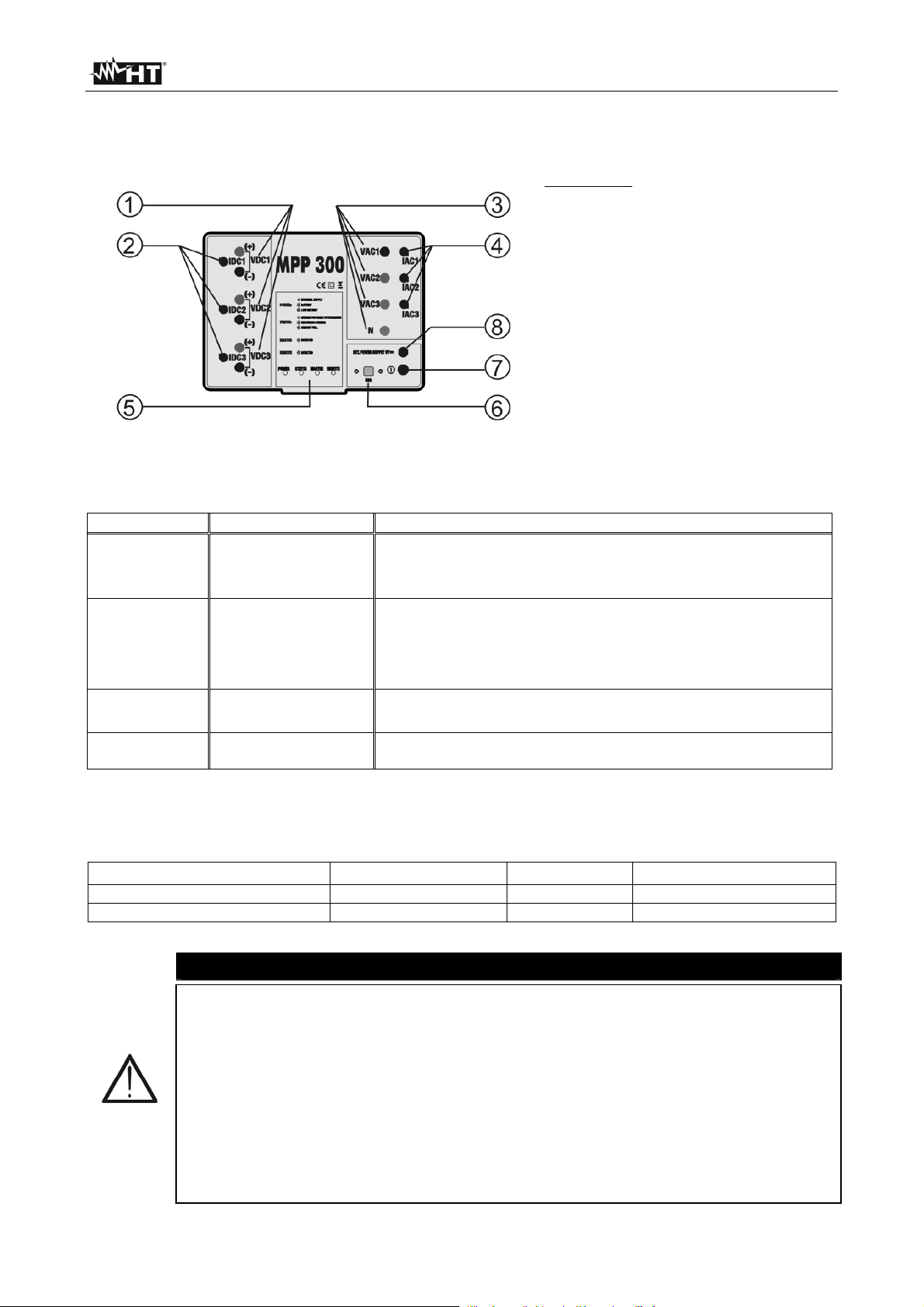
CAPTION:
1. DC voltage inputs
2. DC current inputs
3. AC voltage inputs
4. AC current inputs
5. Indication LEDs
6. USB connector (only for
MASTER instruments of Type
2, see § 4.3)
7. ON/OFF key
8. Connector for external supply
Fig. 1: Description of the instrument’s front panel
4.2. DESCRIPTION OF THE INDICATION LEDS
LED name Status Description
POWER
STATUS
MASTER
REMOTE
GREEN steady
GREEN flashing
RED flashing
GREEN steady
GREEN flashing
RED flashing
RED steady
GREEN flashing
OFF
GREEN flashing
OFF
MPP300 supplied by external power supply
MPP330 supplied by internal batteries
Batteries of MPP300 almost flat
MPP300 in synchronization phase before starting recording
MPP300 in recording phase
MPP300 memory full
Internal error of MPP300 (see § 4.3.1 and Message table in the
User Manual of the MASTER instrument)
MPP300 is connecting to the MASTER unit
MPP300 is NOT connecting to the MASTER unit
MPP300 is connecting to unit SOLAR-02
MPP300 is NOT connecting to unit SOLAR-02
Table 1: Description of the indication LEDs on MPP300
4.3. MASTER INSTRUMENT
MPP300 may be controlled only by the following MASTER instruments:
MASTER instrument Instrument type Firmware Fw update
SOLAR I-V 1 (RF connection) 5.02 or higher C a n b e c a r r i e d o u t b y t h e u se r
SOLAR 300N 2 (USB connection) 1.27 or higher Ca n b e c a rr i e d o u t b y t h e u s e r
Table 2: Characteristics of the MASTER instruments
All controls are sent to the instrument via RF communication (MASTER
instrument of Type 1) or via USB port (MASTER instrument Type 2)
We recommend the user verifies that the software version (Firmware) in
the MASTER instrument to which MPP300 should be connected is
consistent with the indications given in Table 2. This information is present
in the initial screen shown when switching on the MASTER instrument.
The results of the measurements carried out by MPP300 are sent to the
MASTER instrument to which it is connected and shown on the master
instrument’s display. All measures stored in the MASTER instrument’s
memory can be subsequently displayed and can be transferred to a PC
CAUTION
EN - 6
Page 9
MPP300
4.3.1. Displaying the status of MPP300 by means of MASTER instruments of Type 1
In case the MASTER instrument is near MPP300, it is possible to display the general
parameters and obtain information about a possible error state of MPP300 (STATUS LED
red steady). For a description of the error conditions, please refer to the Message table in
the User Manual of the MASTER instrument
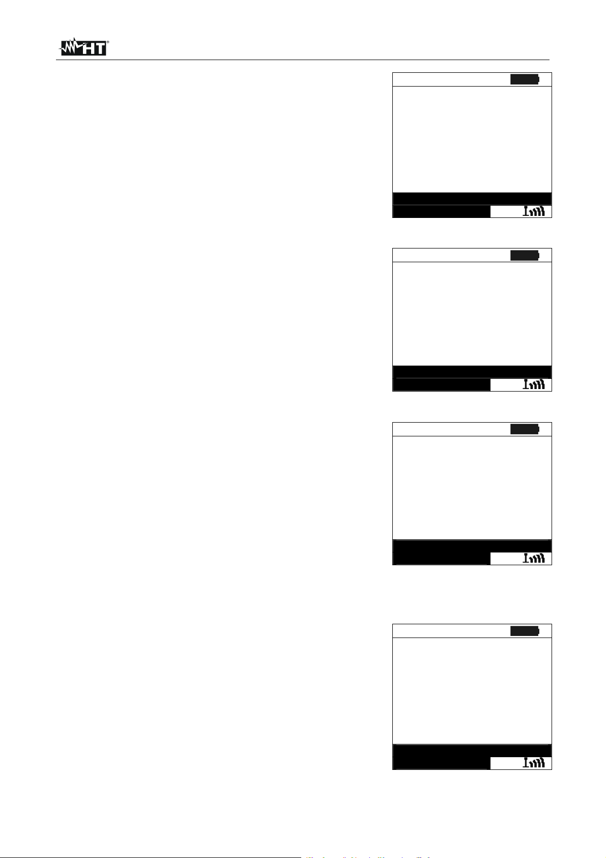
1. Position the cursor onto EFF by using the arrow keys
(,) and confirm with ENTER. The display shows the
screen here to the side, which contains the global
parameters of the system
15/05/10 15:34:26
PRp - - -
Irr - - - W/m2
Pnom 150.0 kW
Tc - - - °C
Te - - - °C
Pdc - - - kW
Pac - - - kW
ndc - - -
nac - - -
GO – start rec
Select
MPP
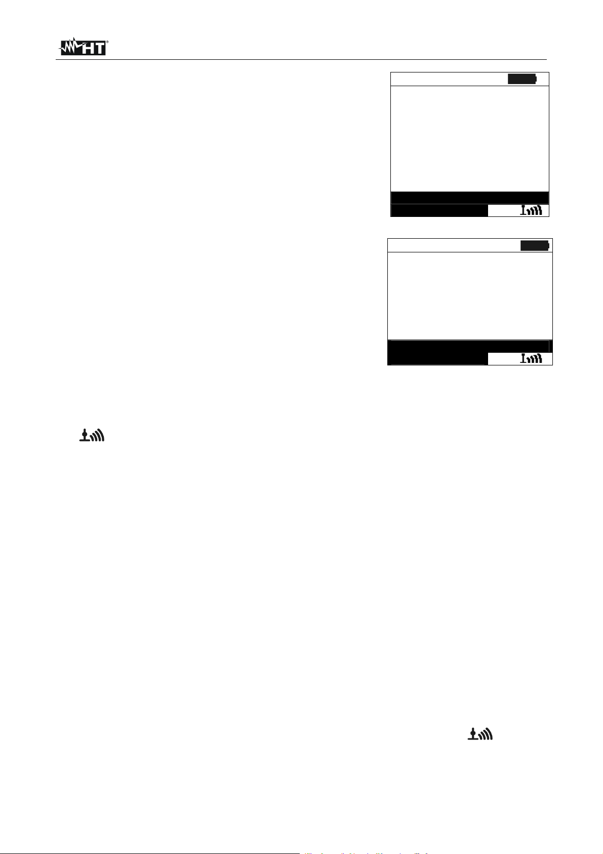
2. Press the ENTER key. The instrument shows the
following options: MPP300 status, Set PV Plant and Set
Instrument
3. Use the arrow keys (,) to select “MPP300 status” and
confirm with ENTER. The instrument shows the screen
here to the side, which indicates the main general
parameters of the instrument
15/05/10 15:34:26
Power supply Batt
Battery In use
Charge 99%
SOLAR-02 detected SI
Version 1.01
SN 11010030
MPP300 Status
Set .PV plant
Set Instrument
Select
MENU
4.3.2. Displaying the status of MPP300 by means of MASTER instruments of Type 2
In case the MASTER instrument is connected to MPP300 though USB cable, it is possible
to display the general parameters and obtain information about a possible error state of
MPP300 (STATUS LED red steady). For a description of the error conditions, please refer
to the Message table in the User Manual of the MASTER instrument
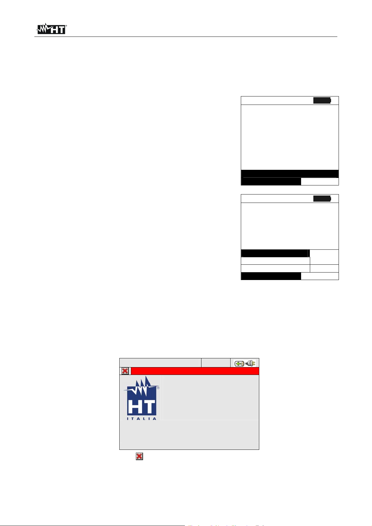
In GENERAL MENU select the “Instrument informations” icon and press ENTER key. The
herewith screen is shown by the instrument:
12/09/2006 – 16:55:10
INSTRUMENT INFORMATIONS
Model: MPP300
SN: xxxxxxxx
Hw: xx
Fw: 1.xx
Press ESC key (or smart icon ) to back to GENERAL MENU screen.
EN - 7
Page 10
MPP300
5. SETTINGS ON MASTER INSTRUMENTS
Instructions are given according to the Type of instruments, classified according to Table 2.
Further in this manual, a brief description is provided of the settings of the MASTER
instrument for use together with MPP300. For an exhaustive description of the controls
and functions of the MASTER instrument, please refer to the User Manual of the
instrument itself.
5.1. MASTER INSTRUMENTS OF TYPE 1 - REMOTE UNIT SETTINGS
Turn on the instrument, press the MENU key, position the cursor onto SET by using the
arrow keys (,) and confirm with ENTER. The display shows the screen which lists the
different settings of the instrument
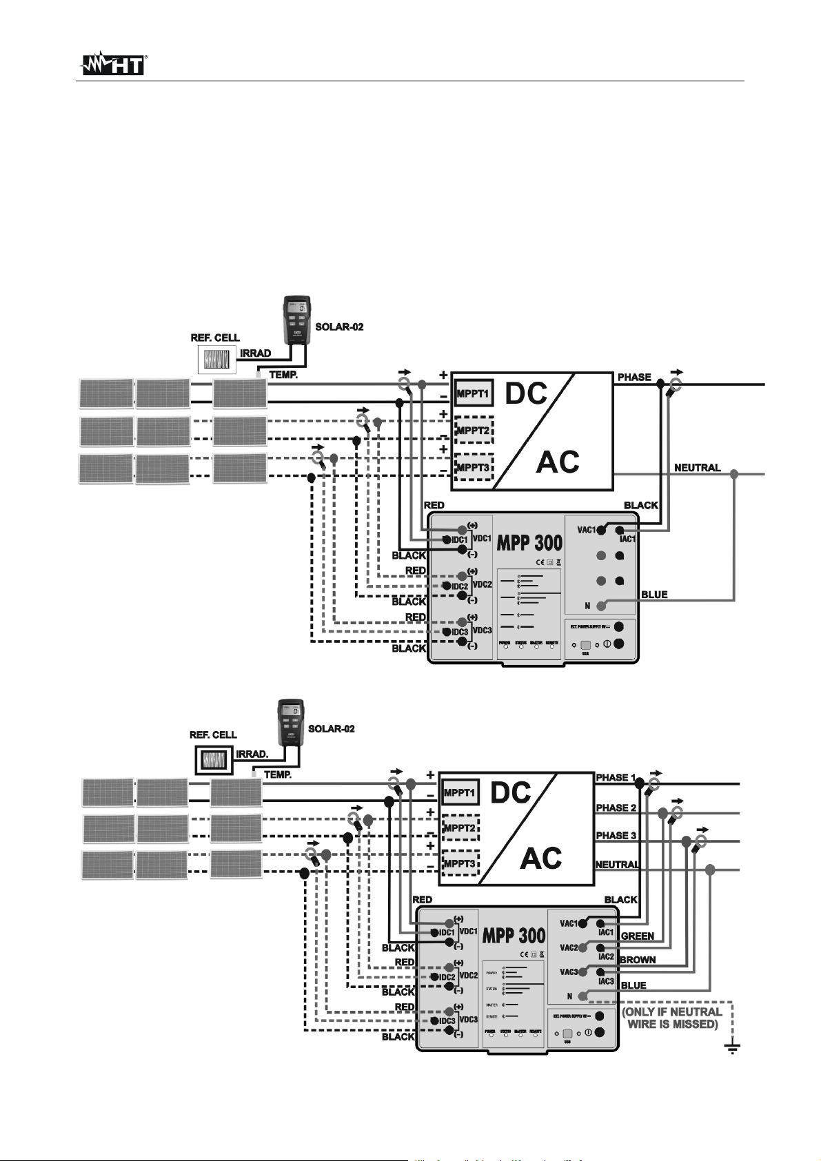
1. Position the cursor onto Remote Unit by using the arrow
keys (,) and confirm with ENTER
2. In parameter “Remote U EFF”, set MPP300
3. Press SAVE to confirm
15/05/10 15:34:26
Remote U EFF MPP300
Remote U I-V NO
Sens.
Alpha : 0.060 %/°C
:31.0mV/kW/m2
SAVE to save
SET
5.2. MASTER INSTRUMENTS OF TYPE 2 – REMOTE UNIT SETTINGS
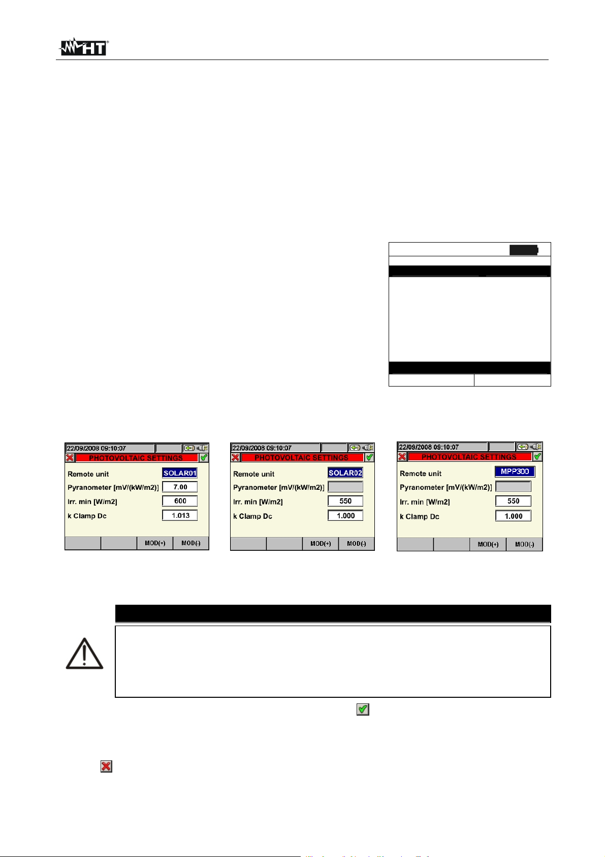
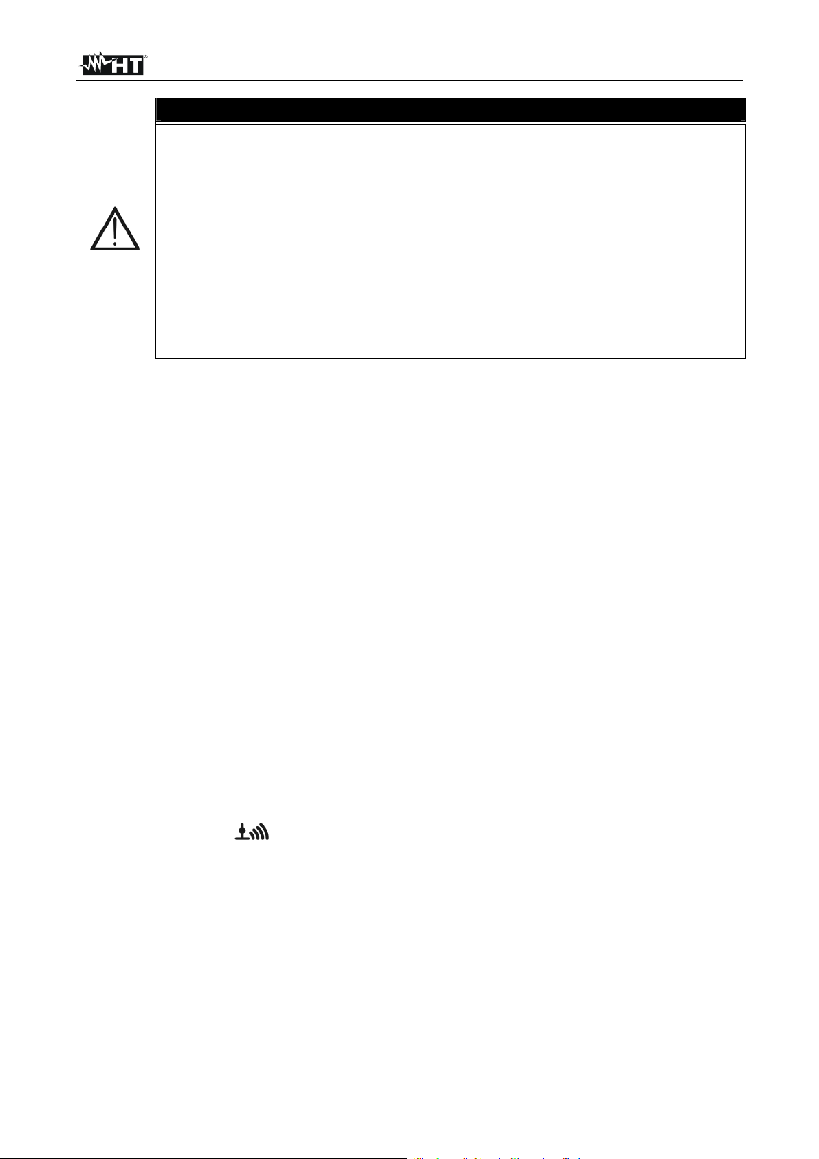
In the GENERAL MENU select ANALYZER SETTINGS, press the F2 key or touch the
“ADVANCED” item on the display. The herewith screens are shown by the meter:
Selection of rem. U. SOLAR-01 Selection of rem. U. SOLAR-02 Selection of rem. U. MPP300
1. By means of the F3 or F4 key (or items MOD(+) or MOD(-) on the display), select the
desired unit SOLAR01 or SOLAR02, MPP300
CAUTION
The selection of remote unit MPP300 automatically disables the “Pyranometer”
field as the sensitivity of the used irradiance probe (pyranometer or reference
cell) should be set inside the internal menu of SOLAR-02 (see user manual of
SOLAR-02). The selection of the type of system MPP-1 or MPP-3 shall
automatically force MPP300 as remote unit type.
2. Press the SAVE or ENTER key (or the smart icon ) to save the selected setting by
confirming with “Ok”. In this way, the settings made will remain valid also after turning
off the instrument.
3. To quit the settings made or to exit without saving, press the ESC key (or the smart
icon ).
EN - 8
Page 11
MPP300
6. OPERATING INSTRUCTIONS
Further in this manual, a brief description is provided of the use of MPP300 together with
the MASTER instrument. For an exhaustive description of the controls and functions of the
MASTER instrument, please refer to the User Manual of the instrument itself.
For the sake of simplicity, further in this manual, the word “string” will be used, although
often the term “photovoltaic field” would be more correct. From the point of view of the
instrument, the management of a single string or of more parallel strings (photovoltaic field)
is identical. Furthermore, the acronym MPPT (Multiple Power Point Tracker) shall indicate
the characteristic of the DC/AC converter (inverter), capable of maximizing the DC power
which can be taken from the photovoltaic field, the acronym PRp shall indicated the
Performance ratio (evaluated on active powers). See § 9.1 for further details
For the evaluation of the PRP only, the measurement of the DC (voltage and
current) is not strictly necessary. Conversely it is necessary if you want to
evaluate the performance of the photovoltaic section (ndc) and DC / AC
conversion (nac)
6.1. PV SYSTEM TESTING FOR INSTRUMENTS OF TYPE 1 (SOLAR I-V)
6.1.1. Testing of PV systems with single/multi-MPPT inverter - single/three-phase AC output
The instrument SOLAR I-V, used together with remote units SOLAR-02 and MPP300,
allows testing PV systems characterized by 1 or more strings (with the same direction and
inclination) and single-phase or three-phase output
The remote unit MPP300 is capable of communicating with SOLAR I-V (to manage
synchronization and data download) and with the remote unit SOLAR-02 (for recording
irradiation and temperature values) via a wireless radiofrequency (RF) connection, which
is active up to a maximum distance of 1m between the units
ATTENTION
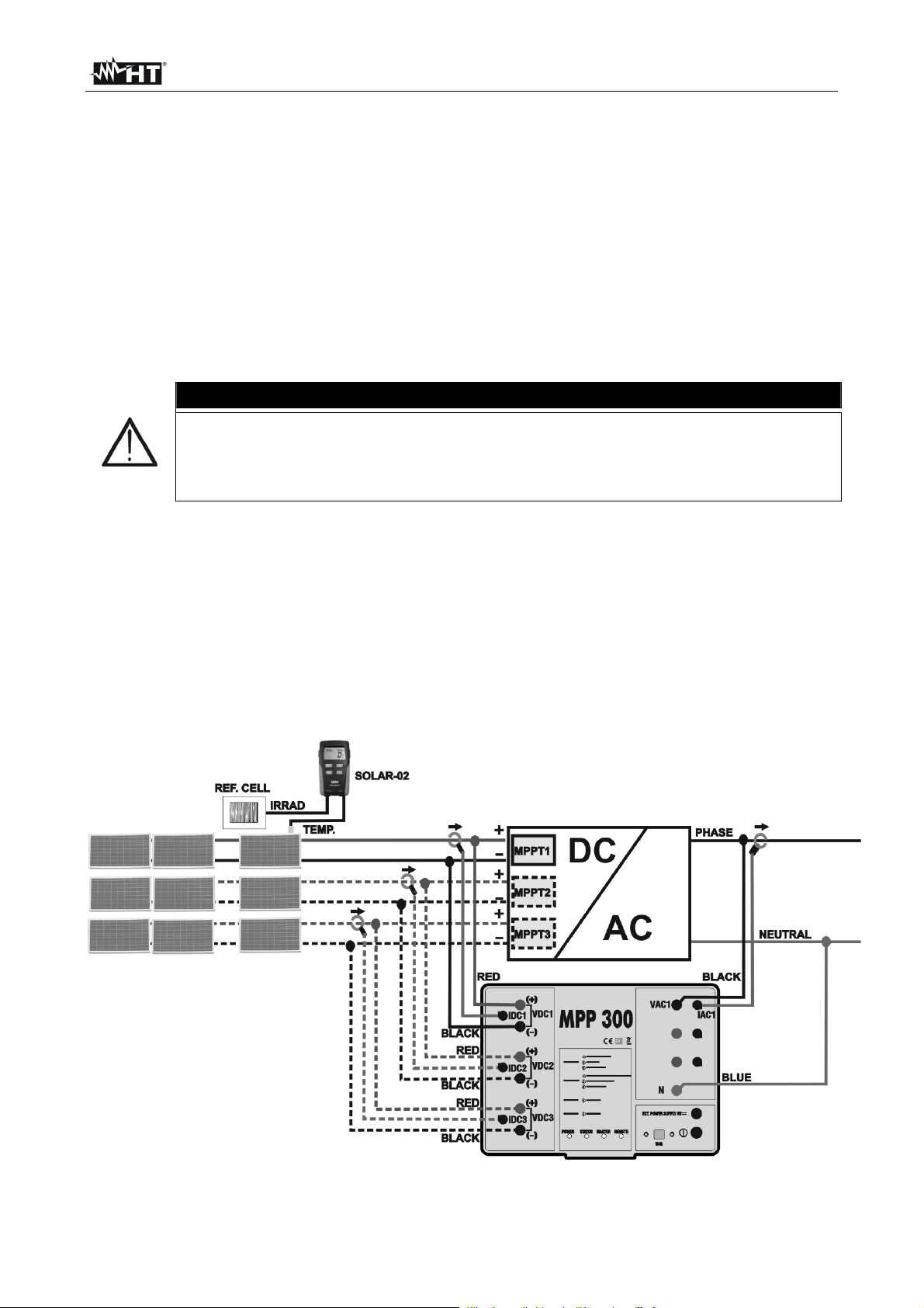
Fig. 2: Connection of MPP300 for testing a single-phase PV system
EN - 9
Page 12
MPP300
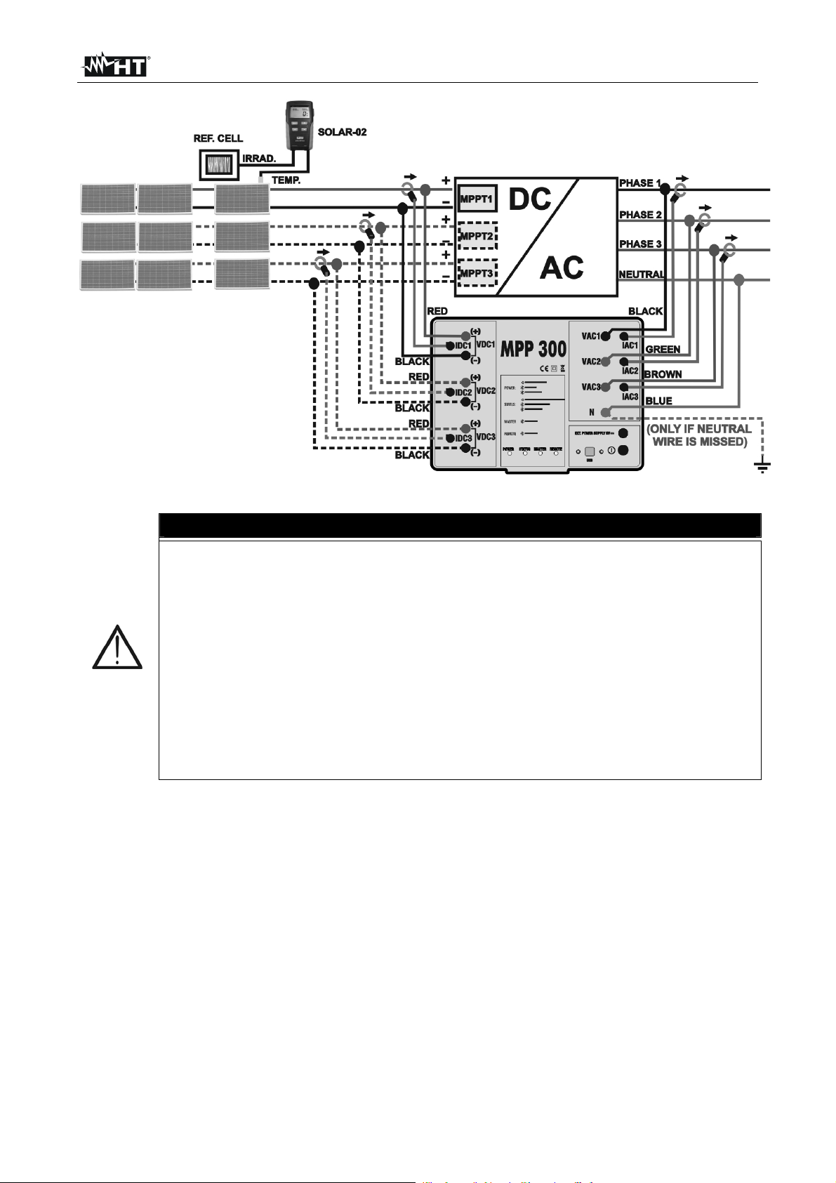
Fig. 3: Connection of MPP300 for testing a three-phase PV system
CAUTION
When SOLAR I-V is set in order to use MPP300 as a remote unit, ALL
connections relevant to electrical quantities (voltages and currents) must
be carried out on unit MPP300. SOLAR I-V must have no voltage nor
current connected to its inputs
The maximum voltage for the inputs of MPP300 is 1000VDC between
inputs VDC1, VDC2, VDC3 and 600VAC between inputs VAC1, VAC2,
VAC3. Do not measure voltages exceeding the limits given in this manual.
Exceeding these limits could result in electrical shocks to the user and
damage to the instrument
In order to guarantee the operator’s safety, while making the connections,
disable the system being measured by means of the switches/breakers
upstream and downstream of the DC/AC converter (inverter)
1. Check and, if necessary, set the sensitivity of the reference cell on SOLAR-02 consistently
with the type of PV modules which will be measured (please refer to the user manual of
SOLAR-02)
2. We recommend making a preliminary evaluation of the value of irradiation on the surface of
the PV modules being tested by means of unit SOLAR-02 (operating independently) and the
reference cell
3. Switch on SOLAR I-V, check and, if necessary, change the settings relevant to the type of
remote unit, to the minimum irradiation threshold, to the full scale of the AC and DC clamps,
to the integration period and to the parameters of the system being measured (see the User
Manual of SOLAR I-V)
4. In order to guarantee the operator’s safety, disable the system being measured by means of
the switches/breakers upstream and downstream of the DC/AC converter (inverter)
EN - 10
Page 13
MPP300
5. Bring SOLAR I-V, SOLAR-02 and unit MPP300 nearer (maximum distance of 1m between
them). All instruments must be switched on (see the User Manuals of SOLAR-2 and
MPP300 for further details)
6. On SOLAR I-V, press the MENU key, select the function EFF and press ENTER; wait for
the three units to start communicating with each other. This condition is highlighted by the
contemporary presence of the following indicators:
Symbol steady (not flashing) on the display of SOLAR I-V
Symbol steady (not flashing) on the display of SOLAR-02
MASTER and REMOTE LEDs flashing green on unit MPP300
7. Connect the VDC1(+) and VDC1(-) inputs of unit MPP300 to the output terminals of the
string, respecting the polarities and the colors indicated in Fig. 2 or Fig. 3.
8. Repeat the operation described in the step above for other possible DC power trackers to be
monitored by using the VDC2 and VDC3 inputs according to the number of DC inputs set
(see the user manual of SOLAR I-V)
9. Connect the output connector of the DC clamp to the IDC1 input of unit MPP300
CAUTION
BEFORE CONNECTING THE DC CLAMPS TO THE CONDUCTORS
Switch on the clamp, check the LED indicating the status of the clamp’s
internal batteries (if present), select the correct range, press the ZERO key
on the DC clamp and check on the display of SOLAR I-V the actual zeroing
of the corresponding Idc value (values up to 0.02A are acceptable)
10. Insert the DC current clamp onto the positive output conductor of the string, respecting
the direction of the arrow found on the clamp itself as indicated in in Fig. 2 or Fig. 3.
Position the clamp toroid as far as possible from the inverter and from the negative
output conductor of the string itself
11. Repeat the operations described in the two steps above for other possible DC power
trackers to be monitored by using the IDC2 and IDC3 inputs according to the number of
DC inputs set (see the User Manual of SOLAR I-V)
12. Connect the VAC1 and N inputs of unit MPP300 to the Phase and Neutral conductors
respectively, respecting the polarities and the colours indicated in Fig. 2 or Fig. 3. In
case of three-phase systems in which no Neutral conductor is available, connect input
N to earth
13. In case of inverter with three-phase output (see the User Manual of SOLAR I-V), repeat
the operation described in the step above for the remaining phases by using the VAC2
and VAC3 inputs of MPP300
14. Connect the AC clamp to the Phase L1 conductor, respecting the direction of the
arrow found on the clamp itself as indicated in Fig. 2 or Fig. 3. Position the clamp
toroid as far as possible from the inverter and from the Neutral conductor. Connect the
clamp output to the IAC1 input of MPP300
15. In case of inverter with three-phase output (see the User Manual of SOLAR I-V), repeat
the operation described in the step above for the remaining phases by using the IAC2
and IAC3 inputs of MPP300
16. Restore the operation of the electrical system being measured
EN - 11
Page 14
MPP300
0.9
0.9
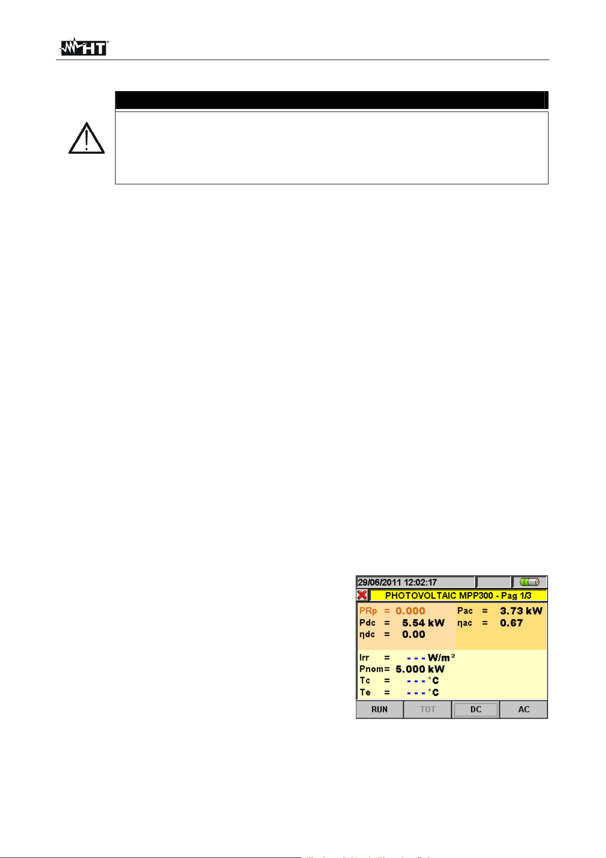
17. The display of SOLAR I-V will show the values of the
general electrical parameters of the system being
measured
In particular, in this screen:
Pdc = General dc power (sum of the string powers)
Pac = ac power (if single-phase) or sum of the ac powers (if
three-phase)
We recommend checking that the values of the electrical
parameters (Pnom, Pdc, Pac) and of the ac performance
(ac) are consistent with the system being measured (e.g.:
ac > 1 is not physically acceptable)
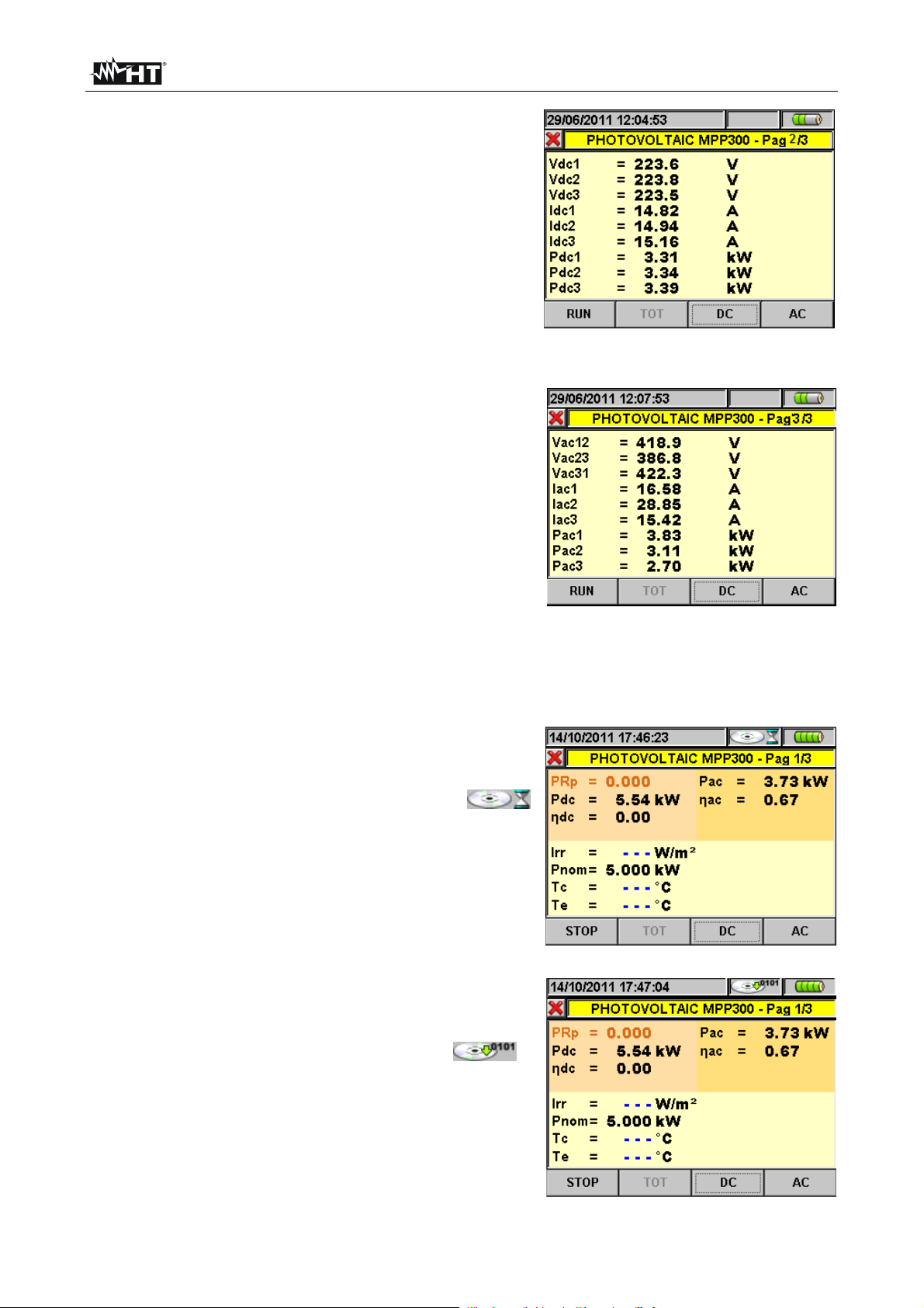
18. On SOLAR I-V, press key () to access the second
screen which contains the values of the output DC
parameters of the strings according to the number of DC
inputs set (see the User Manual of SOLAR I-V)
In particular, in this screen:
Vdcx = dc voltage of string x.
Idcx = dc current of string x.
Pdx = dc power of string x.
We recommend checking that the values of the electrical
parameters (Vdc, Idc, Pdc) are consistent with the system
being measured
19. On SOLAR I-V, press key () to access the third screen
which contains the values of the electrical parameters on
the AC side of the inverter, consistently with the settings
made (see – SOLAR I-V user’s manual, single-phase,
three-phase 4 wires).
In particular, in this screen:
Vacxy = ac voltage between Phase and Neutral (if singlephase) or between Phases x and y (if three-phase)
Iacx = ac current of phase x
Pacx = ac power of phase x
We recommend checking that the values of the electrical
parameters (Vac, Iac, Pac) are consistent with the system
being measured
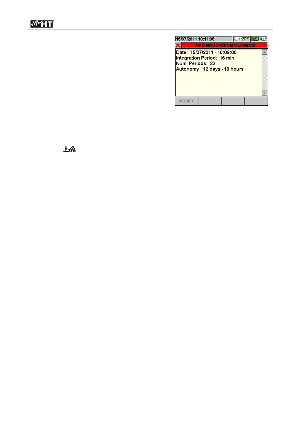
20. Keeping the three instruments near each other (max distance
approx. 1m), press the GO/STOP key on SOLAR I-V to start
testing. Consequently:
The display of SOLAR I-V shows the message “Rec. start
waiting”
The display of SOLAR-02 shows the message “HOLD” and
the time, expressed in seconds, remaining before the
recording is started
On MPP300, the STATUS LED turns on green (not flashing)
15/05/10 15:34:26
PRp - - -
Irr - - - W/m2
Pnom 3.500 kW
Tc - - - °C
Te - - - °C
Pdc 3.125 kW
Pac 2.960 kW
ndc - - -
nac
GO – start rec
Select
15/05/10 15:34:26
Vdc1 460.1 kW
Vdc2 461.4 V
Vdc3 462.5 A
Idc1 2.25 A
Idc2 2.31 A
Idc3 2.21 A
Pdc1 1.035 kW
Pdc2 1.066 kW
Pdc3 1.024 kW
GO – start rec
Select
15/05/10 15:34:26
Vac12 401.4 V
Vac23 401.1 V
Vac31 400.1 V
Iac1 4.26 A
Iac2 4.26 A
Iac3 4.27 A
Pac1 987 W
Pac2 986 W
Pac3 985 W
GO – start rec
Select
Example of a screen for
PV systems with threephase output
15/05/10 15:34:26
PRp - - -
Irr - - - W/m2
Pnom 3.500 kW
Tc - - - °C
Te - - - °C
Pdc 3.125 kW
Pac 2.960 kW
ndc - - -
nac
Rec.Start Waiting
Select
5
MPP
MPP
MPP
5
MPP
EN - 12
Page 15
MPP300
0.9
21. Upon reaching the instant “00” after pressing the GO/STOP
key, the test is started and the three units are
synchronized with each other. In these conditions:
The display of SOLAR I-V shows the message “rec.
running”
The display of SOLAR-02 shows the message
“Recording…”
On MPP300, the STATUS LED flashes green
22. At any time it will be possible to analyze the current
recording status by pressing the MENU key. The following
information will be shown:
starting date and time of recording
the value set for the integration period
the number of periods elapsed from the beginning of the
recording
the remaining memory capacity for recording
Press the ESC key to exit the screen
15/05/10 15:35:00
PRp - - -
Irr - - - W/m2
Pnom 3.500 kW
Tc - - - °C
Te - - - °C
Pdc 3.125 kW
Pac 2.960 kW
ndc - - -
nac
Rec. running
Select
15/05/10 15:35:00
Start
14/02/00 17:18:00
Period: 5s
IP Number 61
Rec. time 0d 1h
Reg. in corso
Rec running
Select
5
MPP
MPP
23. Now it is possible to bring the unit SOLAR-02 near the PV strings to measure irradiation and
temperature by means of the relevant probes. When the distance between unit SOLAR-02
and MPP300 does not allow the RF connection, on the display of SOLAR-02 the symbol
“ ” flashes for approx 30s and then disappears. Unit MPP300 steadily searches for the
RF connection with unit SOLAR-02
24. Position the reference cell onto the surface of the PV modules. Please refer to the relevant
User Manual for a correct assembly
25. Put the temperature sensor in contact with the rear side of the panel and fasten it with some
tape; prevent touching it with your fingers (as this could alter the measure)
26. Wait for a few seconds to allow the probes to reach a steady measure and then connect the
irradiation probe to input PYRA/CELL and the temperature probe to input TEMP of unit
SOLAR-02
27. Wait for the message “READY” to appear on the display of SOLAR-02 to indicate that the
unit has detected the data with solar irradiation > minimum threshold set (see the User
Manual of SOLAR I-V)
28. With the message “READY” shown on the display, wait for approximately 1 minute in
order to take a certain number of samples
29. Disconnect the irradiation and temperature probes from unit SOLAR-02 and bring the unit
near unit MPP300. Bring the main unit SOLAR I-V near MPP300 too. The three units
must be near each other (max distance 1m)
30. The main unit SOLAR I-V must be in EFF mode; if no flashing symbol “ ” appears,
press key to activate the RF connection search again
31. Press key on SOLAR-02 to activate the RF connection again. Consequently, the main
unit will show the message “radio connection activated”
EN - 13
Page 16

MPP300
0.82
971
30
0.9
32. To stop testing, press the GO/STOP key on instrument
SOLAR I-V and confirm with ENTER that you want to stop
recording
33. The display of SOLAR I-V will show the message “DATA
DOWNLOAD” to indicate that the data will be transferred to
the main unit during its various phases
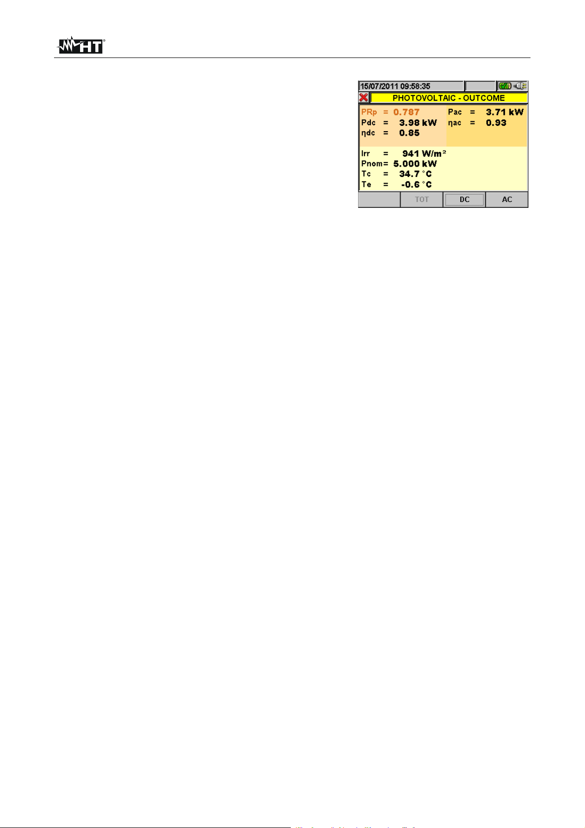
34. After the automatic data transfer phase, the instrument:
Do not show any results if do not exist on the PV
installation a “stable irradiance” condition more than the
minimum irradiance threshold (see see user’s manual of
MASTER instrument) or all PRp values are not valid (PRp
> 1.15).
Display the best performance values if during the
recording, the Irradiance values reached the “stable”
condition and its values were higher than the minimum
irradiance threshold (see user’s manual of MASTER
instrument).
35. Press SAVE to save the results or ESC to exit the screen of
the results and go back to the initial screen
15/05/10 15:35:00
PRp
Irr
Pnom 3.500 kW
Tc 45.1 °C
Te
Pdc 3.125 kW
Pac 2.960 kW
ndc 0.86
nac
Analysis Result
Select
W/m2
.5 °C
5
MPP
EN - 14
Page 17
MPP300
6.2. PV SYSTEM TESTING FOR INSTRUMENTS OF TYPE 1 (SOLAR 300N)
6.2.1. Testing of PV systems with single/multi-MPPT inverter - single/three-phase AC output
The instrument SOLAR300N, used together with remote units SOLAR-02 and MPP300
(optional), allows carrying out long recordings on PV systems characterized by 1 or more
PV fields (with the same direction and inclination), each connected to an MPPT of the
inverter (see § 9.1) and single-phase or three-phase output. The remote unit MPP300 is
capable of communicating with SOLAR300N via USB cable (to manage data
synchronization and download) and with the remote unit SOLAR-02 (for recording
irradiation and temperature values) via a wireless radiofrequency (RF) connection, which
is active up to a maximum distance of 1m between the units.
Fig. 4: Connection of MPP300 for testing a single-phase PV system
Fig. 5: Connection of MPP300 for testing a three-phase PV system
EN - 15
Page 18
MPP300
CAUTION
When SOLAR300N is set in order to use MPP300 as a remote unit, ALL
connections relevant to electrical quantities (voltages and currents) must
be carried out on unit MPP300. SOLAR300N must have no voltage nor
current connected to its inputs.
The maximum voltage for the inputs of MPP300 is 1000VDC between
inputs VDC1, VDC2, VDC3 and 600VAC between inputs VAC1, VAC2,
VAC3. Do not measure voltages exceeding the limits given in this manual.
Exceeding these limits could result in electrical shocks to the user and
damage to the instrument.
In order to guarantee the operator’s safety, while making the connections,
disable the system being measured by means of the switches/breakers
upstream and downstream of the DC/AC converter (inverter).
1. Check and, if necessary, set the sensitivity of the reference cell on SOLAR-02
consistently with the type of PV modules which will be measured (please refer to the
User Manual of SOLAR-02).
2. We recommend making a preliminary evaluation of the value of irradiation on the
surface of the PV modules being tested by means of unit SOLAR-02 (operating
independently) and the reference cell
3. Switch on SOLAR300N, check and, if necessary, change the settings relevant to the
type of remote unit, to the minimum irradiation threshold, to the full scale of the AC and
DC clamps, to the parameters of the system being measured and to the value of the
integration period (see SOLAR300N user’s manual).
4. In order to guarantee the operator’s safety, disable the system being measured by
means of the switches/breakers upstream and downstream of the DC/AC converter
(inverter).
5. Connect SOLAR300N to the MPP300 unit via the USB cable and bring SOLAR-02 and
MPP300 nearer (max distance approx. 1 m). All instruments must be switched on
(see the User Manuals of SOLAR-2 and MPP300 for further details). The display of
SOLAR300N must show (for 5 seconds) the message “MPP300 connected”.
6. On SOLAR300N, access the GENERAL MENU, select the function View Measures
and press ENTER; wait for the three units to start communicating with each other. This
condition is highlighted by the contemporary presence of the following indicators:
a. Symbol steady (not flashing) on the display of SOLAR-02
b. MASTER and REMOTE LEDs flashing green on unit MPP300
7. Connect the VDC1(+) and VDC1(-) inputs of the MPP300 unit to the output terminals of
the string, paying attention to the polarity and the colours indicated in Fig. 4 or Fig. 5.
8. Repeat the operation described in the step above for other possible DC power trackers
to be monitored by using the VDC2 and VDC3 inputs according to the number of DC
inputs set (see SOLAR300N user’s manual).
EN - 16
Page 19
MPP300
9. Connect the output connector of the DC clamp to the IDC1 input of unit MPP300.
CAUTION
BEFORE CONNECTING THE DC CLAMPS TO THE CONDUCTORS
Switch on the clamp, check the LED indicating the status of the clamp’s
internal batteries (if present), select the correct range, press the ZERO key
on the DC clamp and check on the display of SOLAR300N the actual
zeroing of the corresponding Idc value (values up to 0.02A are acceptable).
10. Insert the DC current clamp onto the positive output conductor of the string, respecting
the direction of the arrow found on the clamp itself as indicated in Fig. 4 or Fig. 5.
Position the clamp toroid as far as possible from the inverter and from the negative
output conductor of the string itself.
11. Repeat the operations described in the two steps above for other possible DC power
trackers to be monitored by using the IDC2 and IDC3 inputs according to the number of
DC inputs set(see SOLAR300N user’s manual).
12. Connect the VAC1 and N inputs of unit MPP300 to the Phase and Neutral conductors
respectively, respecting the polarities and the colours indicated in in Fig. 4 or Fig. 5. In
case of three-phase systems in which no Neutral conductor is available, connect input
N to earth.
13. In case of inverter with three-phase output (see SOLAR300N user’s manual), repeat
the operation described in the step above for the remaining phases by using the VAC2
and VAC3 inputs of MPP300.
14. Connect the AC clamp to the Phase L1 conductor, respecting the direction of the arrow
found on the clamp itself as indicated in Fig. 4 or Fig. 5. Position the clamp toroid as far
as possible from the inverter and from the Neutral conductor. Connect the clamp output
to the IAC1 input of MPP300.
15. In case of inverter with three-phase output (see SOLAR300N user’s manual), repeat
the operation described in the step above for the remaining phases by using the IAC2
and IAC3 inputs of MPP300.
16. Restore the operation of the electrical system being measured.
17. The display of SOLAR300N will show the values
of the general electrical parameters of the system
being measured.
In particular, in this screen:
Pdc = General dc power (sum of the string powers)
Pac = ac power (if single-phase) or sum of the ac
powers (if three-phase)
We recommend checking that the values of the
electrical parameters (Pnom, Pdc, Pac) and of the ac
performance (ac) are consistent with the system
being measured (e.g.: ac > 1 is not physically
acceptable).
EN - 17
Page 20
MPP300
18. On SOLAR300N, press key F3 to access the
second screen which contains the values of the
output DC parameters of the strings according to
the number of DC inputs set (see SOLAR300N
user’s manual).
In particular, in this screen:
Vdcx = dc voltage of string x.
Idcx = dc current of string x.
Pdx = dc power of string x.
We recommend checking that the values of the
electrical parameters (Vdc, Idc, Pdc) are consistent
with the system being measured.
19. On SOLAR300N, press key F4 to access the third
screen which contains the values of the electrical
parameters on the AC side of the inverter,
consistently with the settings made (see
SOLAR300N user’s manual - single-phase, threephase 4 wires).
In particular, in this screen:
Vacxy = ac voltage between Phase and Neutral (if
single-phase) or between Phases x and y (if threephase)
Iacx = ac current of phase x
Pacx = ac power of phase x
We recommend checking that the values of the
electrical parameters (Vac, Iac, Pac) are consistent
with the system being measured.
20. Keeping the three instruments connected, press the
F1 key on SOLAR300N to start recording.
Consequently:
a. The display of SOLAR300N shows the icon .
The display of SOLAR-02 shows the message
“HOLD” and the time, expressed in seconds,
remaining before the recording is started
b. On MPP300, the STATUS LED turns on green (not
flashing)
Example of a DC screen for PV
systems with 3 MPPTs
Example of an AC screen for PV
systems with three-phase
output
21. Upon reaching the instant “00” afte r pres sin g the F1
key, the test is started and the three units are
synchronized with each other. In these conditions:
a. The display of SOLAR300N shows the icon .
b. The display of SOLAR-02 shows the message
“Recording…”
c. On MPP300, the STATUS LED flashes green
EN - 18
Page 21
MPP300
22. At any time while recording it will be possible to
analyze its current status by selecting the button
Saved data management in the GENERAL
MENU. The following information will be shown:
a. starting date and time of recording
b. the value set for the integration period
c. the number of periods elapsed from the
beginning of the recording
d. the remaining memory capacity for
recording
Press the ESC key to exit the screen
23. Now it is possible to bring the unit SOLAR-02 near the PV strings to measure irradiation and
temperature by means of the relevant probes. When the distance between unit SOLAR02 and MPP300 does not allow the RF connection, on the display of SOLAR-02 the
symbol “
” flashes for approx 30s and then disappears. Unit MPP300 steadily
searches for the RF connection with unit SOLAR-02.
24. Position the reference cell onto the surface of the PV modules. Please refer to the relevant
User Manual for a correct assembly.
25. Put the temperature sensor in contact with the rear side of the module and fasten it with
some tape; prevent touching it with your fingers (as this could alter the measure).
26. Wait for a few seconds to allow the probes to reach a steady measure and then connect the
irradiation probe to input PYRA/CELL and the temperature probe to input TEMP of unit
SOLAR-02.
27. Wait for the message “READY” to appear on the display of SOLAR-02 to indicate that the
unit has detected the data with solar irradiation > minimum threshold set (see SOLAR300N
user’s manual).
28. With the message “READY” shown on the display, wait for a time period at least equal to the
set integration period (see SOLAR300N user’s manual) in order to take a significant number
of samples (>=2).
29. Disconnect the irradiation and temperature probes from unit SOLAR-02 and bring the unit
near unit MPP300. The two units must be near each other (max distance 1m).
30. Connect (if disconnected) the SOLAR300N unit to the MPP300 unit. The MASTER LED
must always be flashing to indicate the connection between SOLAR300N and MPP300.
31. Press key on SOLAR-02 to activate the RF connection again. Consequently, the
REMOTE LED on unit MPP300 will start flashing.
EN - 19
Page 22
MPP300
32. To stop recording, press the GO/STOP key on the
instrument SOLAR300N and confirm with ENTER that
you want to stop recording.
33. The display of SOLAR300N will show various
messages indicating the different phases of data
transfer to the main unit. The transferred data will be
saved automatically.
34. After the automatic data transfer phase, the
instrument:
Do not show any results if do not exist on the PV
installation a “stable irradiance” condition more
than the minimum irradiance threshold (see see
user’s manual of MASTER instrument) or all PRp
values are not valid (PRp > 1.15).
Display the best performance values if during the
recording, the Irradiance values reached the “stable”
condition and its values were higher than the
minimum irradiance threshold (see user’s manual of
MASTER instrument).
35. Press SAVE to save the obtained results. Pressing the
key will display the virtual keyboard for adding possible
comments. Further pressing the SAVE key will archive
the measure and the added comments and will go back
to the initial screen for a new measurement.
Example of a result combined
with MPP300
EN - 20
Page 23
MPP300
7. MAINTENANCE
7.1. GENERAL INFORMATION
The instrument you purchased is a precision instrument. While using and storing the
instrument, carefully observe the recommendations listed in this manual in order to prevent
possible damage or danger during use. Do not use the instrument in environments with
high humidity levels or high temperatures. Do not expose to direct sunlight. Always switch
off the instrument after use.
7.2. STATUS OF THE INTERNAL RECHARGEABLE BATTERIES
The status of the POWER LED provides indications about the operating/charge status of
the instrument’s internal rechargeable batteries
POWER: GREEN steady: MPP300 supplied by external power supply
GREEN flashing: MPP330 supplied by internal batteries
RED flashing: Batteries of MPP300 almost flat
In case the LED indicates the condition of almost flat batteries, we
recommend connecting the instrument to power supply. It is not necessary
to stop possible measurements in progress to connect the power supply
If the instrument detects a too low battery voltage, it stops possible
recordings in progress and switches off
The instrument maintains the data stored also in case of flat battery
7.3. CLEANING THE INSTRUMENT
Use a soft and dry cloth to clean the instrument. Never use wet cloths, solvents, water, etc
7.4. END OF LIFE
CAUTION
CAUTION: this symbol indicates that the appliance, its accessories and the
internal batteries must be collected separately and correctly disposed of
EN - 21
Page 24
MPP300
8. TECHNICAL SPECIFICATIONS
8.1. TECHNICAL SPECIFICATIONS FOR TEST ON PV SYSTEMS
Uncertainty is indicated as [%reading + (no. of digits) * resolution] at 23°C ± 5°C, <80%HR
DC voltage
Range [V] Resolution [V] Uncertainty
10.0 999.9
Phase-Neutral AC TRMS voltage
Range [V] Frequency Resolution [V] Uncertainty
10.0 300.0 42.5 69.0Hz
Max peak factor: 1,5
Phase-Phase AC TRMS voltage
Range [V] Frequency Resolution [V] Uncertainty
50.0 594.0 42.5 69.0Hz
Max peak factor: 1,5
DC current (by means of external clamp transducer)
Range Resolution Uncertainty
5.0mV 319.9mV
320.0mV 999.9mV (0.5rdg)
Current values corresponding to a voltage < 5mV are zeroed
0.1mV
AC TRMS current (by means of external clamp transducer STD type)
Range Frequency Resolution Uncertainty
5.0mV 219.9mV
220.0mV 999.9mV (0.5rdg)
Peak factor <= 1.5 – Current values corresponding to a voltage < 5mV are zeroed.
42.5 69.0Hz
0.1mV
AC TRMS current (by means of external clamp transducer of FLEX 8.5uV/A – FS 100A type)
Range Frequency Resolution Uncertainty
0.008 8.50mV 42.5 69.0Hz
Peak factor <= 1.5 – Current values < 1A are zeroed.
0.001mV
AC TRMS current (by means of external clamp transducer of FLEX 8.5uV/A – FS 1000A type)
Range Frequency Resolution Uncertainty
0.085 85.0mV 42.5 69.0Hz
Peak factor <= 1.5 – Current values < 5A are zeroed.
0.01mV
DC power (Vmeas > 150V) ; AC power (Vmeas > 200V, PF=1)
Clamp FS [A] Range [W] Resolution [W] Uncertainty
1< FS 10
10< FS 100
100< FS 1000
Vmeas = voltage at which power is measured; Imeas = measured current
0.000k 9.999k
10.00k 99.99k
0.00k 99.99k
100.0k 999.9k
0.0k 999.9k
1000k 9999k
0.1
0.1
0.1
(0.5rdg + 0.06%FS)
(0.5rdg + 0.06%FS)
(0.5%rdg + 7dgt)
(0.5%rdg + 15dgt)
0.001k
0.01k
0.01k
0.1k
0.1k
1k
(0.5rdg + 2dgt)
(0.5rdg + 2ddgt)
(0.7rdg + 2dgt)
Protection against
overcharge
10V
Protection against
overcharge
10V
Protection against
overcharge
10V
Protection against
overcharge
10V
(0.7rdg + 3dgt)
(Imeas < 10%FS)
(0.7rdg)
(Imeas 10%FS)
EN - 22
Page 25
MPP300
8.2. REFERENCE STANDARDS
Instrument safety: IEC/EN61010-1
Safety of measuring accessories: IEC/EN61010-031
Technical documentation: IEC/EN61187
Insulation: double insulation
Mechanical protection: IP 40
Pollution level: 2
Measurement category: CAT III 1000V DC, Max 1000V between DC inputs
CAT IV 300V AC to earth, max 600V between AC inputs
8.3. GENERAL CHARACTERISTICS
Memory
Memory capacity: 2 MBytes
Integration Period: 5,10,30,60,120,300,600,900,1800,3600s
Battery duration (with SOLAR-02): approx. 1.5 hours (@ PI = 5s)
approx. 8 days (@ PI = 600s)
Characteristics of radio module
Frequency range: 2.400 2.4835GHz
R&TTE category: Class 1
Max transmission power: 30W
Max RF connection distance: 1m (39in)
Power supply
Internal power supply: Internal rechargeable Li-ION battery (3.7V, 1900mAh)
Battery duration >3 hours
External power supply: AC/DC power supply 100240VAC/50-60Hz – 5VDC
Mechanical characteristics
Dimensions (L x W x H): 300 x 265 x 140mm ; (12 x 10 x 6in)
Weight (batteries included): 1.2kg (2lv)
8.4. ENVIRONMENTAL CONDITIONS FOR USE
Reference temperature: 23° ± 5°C (73° ± 41°F)
Operating temperature: 0 ÷ 40°C (32 ÷ 104°F)
Allowable relative humidity: <80%HR
Storage temperature: -10 ÷ 60°C (14 ÷ 140°F)
Storage humidity: <80%HR
Max operating altitude: 2000m (*) (6562ft)
(*) Prescriptions for the use of the instrument at altitudes between 2000 and 5000m
As regards inputs, the instrument must be considered as downgraded to overvoltage
category CAT II 1000V DC and CAT III 300V to earth max 1000V between inputs. The
marks and symbols found on the instrument are valid only when the instrument is used at
altitudes <2000m
CAUTION
This instrument satisfies the requirements of Low Voltage Directive 2006/95/EC
(LVD) and of EMC Directive 2004/108/EC
8.5. ACCESSORIES
See the attached packing list
EN - 23
Page 26
MPP300
9. APPENDIX – THEORETICAL OUTLINE
9.1. TESTING PHOTOVOLTAIC SYSTEMS
According to the requirements of the laws in force, the result of the test depends on
settings about Temperature effects compensation and PRp calculations (see MASTER
instrument settings):
Corr.Typ
e
Tmod
Tamb
or
Tenv
Tcel value PRp calculation
Tcel = PV Module Temp. measured
Tcel = PV module Temp. calculated
G
NOCT
20TambTcel
800
P
PRp
p
Rfv
ca
G
p
2
G
STC
P
n
Guidelin
e
CEI
82-25
(Italian
Guideline)
nDC
Tcel = PV Module Temp. measured
G
PRp
G
STC
p
1
T
100
cel
25
P
ca
P
n
- - -
where:
Symbol Description Meas. unit
G
p
G
STC
P
n
P
ca
Rfv
2
NOCT Normal Operating Cell Temperature (@ 800W/m2, 20°C,
40)-(Tcel- 1
100
C)40Tcel (if 1
C)40Tcel (if
Irradiance on PV module surface
Standard Irradiance = 1000
Nominal Power = sum of all power module (Pmax )
included in the part of PV plant under test
AC Active Power measured
Thermal Corrective factor
Absolute value of Pmax thermal coefficient
AM=1.5, vel. Aria =1m/s).
W/m
W/m
kW
kW
2
2
C%/
C%/
Previous relationship are valid if Irradiance > Min Irraddiance value (see user manual
of the MASTER instrument) and the Irradiance values are “steady”: if IP 1min (Irr
max – Irr min) < 20W/m
2
The final OUTCOME can be:
Non-displayable: if the obtained values are inconsistent (e.g. PRp >1.15) or if
irradiation has never reached a steady value > minimum threshold set (see user’s
manual of MASTER instrument).
The maximum performance point (PRp) of the system
The highest performance (maximum value of PRp) is detected according with previous
relationships.
EN - 24
Page 27
MPP300
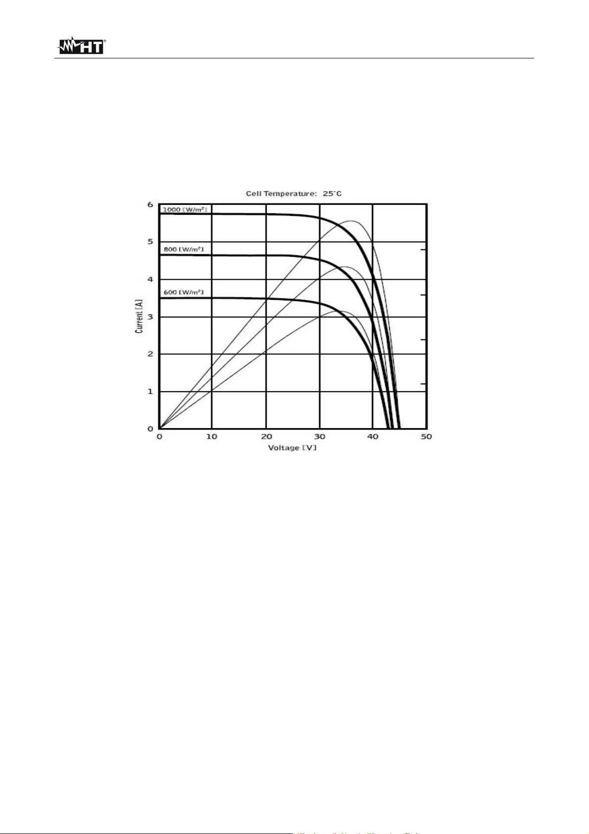
9.2. NOTES ON MPPT (MAXIMUM POWER POINT TRACKER)
Solar irradiation on a surface such as the surface of a photovoltaic system has extremely
variable characteristics, since it depends on the position of the sun with respect to the
surface and on atmospheric conditions (typically, on the presence of clouds). A
photovoltaic module presents, for different solar irradiation values, and for different
temperature values, a range of characteristic curves of the type shown in the following
figure. In particular, the figure shows three I-V curves (in bold) which correspond to three
values (1000, 800, 600W/m2) of solar irradiation
On each characteristic curve there is one single point in which the power transfer towards
a hypothetical charge supplied by the photovoltaic module is maximized. The maximum
power point corresponds to the voltage-current pair for which the product V*I is maximum,
where V is the value of voltage at the module’s terminals and I is the current which runs in
the circuit obtained by closing the module on a hypothetical charge
With reference to the figure above, the product V*I is represented, for the three solar
irradiation values mentioned above, through the three curves in thinner lines
The figure shows that, as stated above, these curves only have one single maximum point.
For example, for 1000W/m2, the maximum power point corresponds to a voltage value of
approx. 36V and to a current value of approx. 5.5A. Obviously, if the power provided by
the system is maximized, it is possible to make the most of the system, both in case the
system is connected to mains, and in case it is stand-alone
MPPT is an inbuilt device in the inverters. It typically reads the voltage and current values
at any instant, calculates their product (i.e. the power in Watts) and, by causing small
variations in the conversion parameters (duty cycle), it is capable of determining, by
comparison, if the photovoltaic module is working in maximum power conditions or not.
According to the result, it operates again on the circuit in order to bring the system to an
optimal condition The reason why MPPTs are used is simple: a photovoltaic system
without MPPTs may operate anyway; however, with the same solar irradiation, it provides
less energy.
EN - 25
Page 28
MPP300
10. SERVICE
10.1. WARRANTY CONDITIONS
This instrument is warranted against any material or manufacturing defect, in compliance
with the general sales conditions. During the warranty period, defective parts may be
replaced. However, the manufacturer reserves the right to repair or replace the product
Should the instrument be returned to the After-sales Service or to a Dealer, transport will
be at the Customer’s charge. However, shipment will be agreed in advance. A report will
always be enclosed to a shipment, stating the reasons for the product’s return. Only use
original packaging for shipment; any damage due to the use of non-original packaging
material will be charged to the Customer. The manufacturer declines any responsibility for
injury to people or damage to property
The warranty shall not apply in the following cases:
Repair and/or replacement of accessories (not covered by warranty)
Repairs that may become necessary as a consequence of an incorrect use of the
instrument or due to its use together with non-compatible appliances
Repairs that may become necessary as a consequence of improper packaging
Repairs which may become necessary as a consequence of interventions performed
by unauthorized personnel
Modifications to the instrument performed without the manufacturer’s explicit
authorization
Use not provided for in the instrument’s specifications or in the instruction manual
The content of this manual cannot be reproduced in any form without the manufacturer’s
authorization
Our products are patented and our trademarks are registered. The manufacturer
reserves the right to make changes in the specifications and prices if this is due to
improvements in technology
10.2. SERVICE
If the instrument does not operate properly, before contacting the After-sales Service,
please check the conditions of the battery and of the cables. Should the instrument still
operate improperly, check that the product is operated according to the instructions given
in this manual
Should the instrument be returned to the After-sales Service or to a Dealer, transport will
be at the Customer’s charge. However, shipment will be agreed in advance. A report will
always be enclosed to a shipment, stating the reasons for the product’s return. Only use
original packaging for shipment; any damage due to the use of non-original packaging
material will be charged to the Customer
EN - 26
Page 29

ESPAÑOL
Manual de Instrucciones
Copyright HT ITALIA 2012 Versión ES 2.00 - 12/10/2012
Page 30

Page 31

MPP300
Indice:
1. PRECAUCIONES Y MEDIDAS DE SEGURIDAD ....................................................... 2
1.1. Instrucciones preliminares ................................................................................................. 2
1.2. Durante el uso ................................................................................................................... 3
1.3. Después del uso ................................................................................................................ 3
1.4. Definición categoría de medida (Sobretensión) ................................................................ 3
2. DESCRIPCIÓN GENERAL ........................................................................................... 4
2.1. Introducción ....................................................................................................................... 4
2.2. Funcionalidad del instrumento .......................................................................................... 4
3. PREPARACIÓN PARA EL USO ................................................................................... 5
3.1. Controles iniciales ............................................................................................................. 5
3.2. Alimentación del instrumento ............................................................................................ 5
3.3. Calibración ........................................................................................................................ 5
3.4. Almacienamiento ............................................................................................................... 5
4. NOMENCLATURA ........................................................................................................ 6
4.1. Descripción del instrumento .............................................................................................. 6
4.2. Descripción LED indicadores ............................................................................................ 6
4.3. Instrumentos MASTER ...................................................................................................... 6
4.3.1. Visualización estado MPP300 a través instrumentos MASTER de Tipo 1 ............................. 7
4.3.2. Visualización estado MPP300 a través instrumentos MASTER de Tipo 2 ............................. 7
5. PROGRAMACIÓN INSTRUMENTOS MASTER .......................................................... 8
5.1. Instrucciones para MASTER tipo 1- Configuración U. remota .......................................... 8
5.2. Instrucciones para MASTER tipo 2- Configuración U. remota .......................................... 8
6. INSTRUCCIONES OPERATIVAS ................................................................................ 9
6.1. Chequeo instal. FV para instrumentos de tipo 1 (SOLAR I-V) .......................................... 9
6.1.1. Te st e o In st a l. F V c o n I nv e rt e r Mo n o/ M ul t i M P PT - S a l id a C A mo n o/ t ri f á si c o .............................. 9
6.2. Chequeo instal. FV para instrumentos de tipo 2 (SOLAR300N) ..................................... 15
6.2.1. Te s t eo Inst a l. FV co n I n v e r t er Mono/ M ul t i MP P T - S a l i d a CA m o n o / t r i f á s i c o ............................ 15
7. MANTENIMIENTO ...................................................................................................... 21
7.1. Generalidades ................................................................................................................. 21
7.2. Estado de las batería internal recargables ...................................................................... 21
7.3. Limpieza del instrumento ................................................................................................ 21
7.4. Fin de vida ....................................................................................................................... 21
8. ESPECIFICACIONES TÉCNICAS .............................................................................. 22
8.1. CaracterÍsticas técnicas verificación instalaciones FV .................................................... 22
8.2. Normas de referencia ...................................................................................................... 23
8.3. Características generales ................................................................................................ 23
8.4. Condiciones ambientales de uso .................................................................................... 23
8.5. Accesorios ....................................................................................................................... 23
9. APENDICE – CONCEPTOS TEÓRICOS ................................................................... 24
9.1. Verificación de las instalaciones FV ................................................................................ 24
9.2. Conceptos sombre MPPT (Maximum Power Point Tracker) ........................................... 25
10. ASISTENCIA .............................................................................................................. 26
10.1. Condiciones de garantía ................................................................................................. 26
10.2. Asistencia ........................................................................................................................ 26
ES - 1
Page 32

MPP300
1. PRECAUCIONES Y MEDIDAS DE SEGURIDAD
El instrumento ha sido proyectado conforme a la directiva IEC/EN61010-1 en relación a
los instrumentos de medida electronicos. Antes y durante la realización de las medidas
atenerse a las siguientes indicaciones y leer con particular atención todas las notas
precedidas con el símbolo
Cuando el instrumento fuera utilizado en modo diverso del especificado en
este manual de instrucciones, las protecciones previstas podrían verse
comprometidas.
No realizar medidas de tensión o corriente en ambientes húmedos
No realizar medidas en presencia de gas o materiales explosivos, combustibles o en
ambientes con polvo
Evite contactos con circuito en examen si no se están realizando medidas
Evite contactos con partes metálicas expuestas, con terminales de medida inutilizados,
circuitos, etc
No realice ninguna medida cuando se encuentren anomalías en el instrumento como,
deformaciones, roturas, fugas de sustancias, ausencia de visualización en el
visualizador, etc
Preste particular atención cuando se realicen medidas de tensión superiores a 20V por
el riesgo de shock elétrico.
Utilice solo los accesorios originales
En este manual y en el instrumento se utilizan los siguientes símbolos:
Atención: atenerse a las instrucciones descritas en el manual; un uso impropio
podría causar daños al instrumento o a sus componentes
Peligro alta tensión: riesgos de shock electrico
Doble aislamiento
Tensión o corriente CC
Tensión o corriente CA
Referencia a tierra
1.1. INSTRUCCIONES PRELIMINARES
Este instrumento ha sido proyectado para uso en ambientes con nivel de polución 2 y
en condiciones ambientales específicas al § 8.4. No use en condiciones ambientales
diferentes
Le invitamos a seguir las reglas normales de seguridad orientadas para protegerla
contra corrientes peligrosas y proteger el instrumento contra un uso erróneo
El instrumento puede ser utilizado para medidas de TENSION en CAT III 1000V CC o
CAT IV 300V CA respecto a tierra. No lo utilice sobre circuitos que superen los límites
especificados en el § 8.1.
El instrumento puede ser utilizado para medidas de CORRIENTE a través de
transductores de pinza externos.
Solo los accesorios originales HT garantizan los estándares de seguridad. Estos
deben estar en buenas condiciones y sustituidos, si fuera necesario, con modelos
idénticos
Antes de conectar los cables de medida al circuito en examen, controle que el
instrumento haya sido correctamente configurado.
ATENCIÓN
ES - 2
Page 33

MPP300
1.2. DURANTE EL USO
Le rogamos que lea atentamente las recomendaciones y las instrucciones siguientes:
ATENCIÓN
La falta de observación de las advertencias y/o instrucciones puede dañar
el instrumento y/o sus componentes o ser fuente de peligro para el
usuario
El LED “POWER“ rojo intermitente indica que las baterías internas
recargables están casi descargadas. Entonces conecte el alimentador
externo como se describe en el § 7.2
Los conectores de entrada del instrumento IDC1, IDC2, IDC3 son del
tipo a 4 pines. Utilice sólo pinzas con conector a 4 pines o
interponga el adaptador ACON3F4M entre la pinza y la entrada del
instrumento.
El instrumento es capaz de mantener los datos memorizados incluso en
condiciones de baterías descargadas
El dispositivo presenta una particular susceptibilidad a las ESD en
proximidad y sobre el puerto USB mientras está operativo, se aconseja la
conexión del cableado a la toma USB con el instrumento apagado
1.3. DESPUÉS DEL USO
Cuando finalicen las medidas, apague el instrumento manteniendo pulsada la tecla
ON/OFF durante algunos segundos. Si se prevee no utilizar el instrumento durante un
largo período atenerse a lo especificado en el § 3.4.
1.4. DEFINICIÓN CATEGORÍA DE MEDIDA (SOBRETENSIÓN)
La norma "IEC/EN61010-1: Prescripciones de seguridad para aparatos electricos de
medida, control y para uso en laboratorio, Parte 1: Prescripciones generales", define lo
que se entiende por categoría de medida, llamada de forma común categoría de
sobretensión. En el § 6.7.4: Circuitos de medida, esta cita:
Los circuitos se subdividen en las siguientes categorías de medida:
La categoría de medida IV sirve para las medidas efectuadas sobre una fuente de
una instalación de baja tensión
Ejemplos son los contadores electricos y las medidas sobre dispositivos primarios de
protección de las sobrecorrientes y sobre las unidades de regulación de la ondulación
La categoria de medida III sirve para las medidas efectuadas en instalaciones en el
interior de edificios
Ejemplos son las medidas sobre paneles de distribución, disyuntores, cableados,
comprendidos los cables, las barras, las cajas de unión, los interruptores, las tomas de
instalación fijas y los aparatos destinados al uso industrial y otras instrumentaciones,
por ejemplo los motores fijos con conexión de instalación fija
La categoria de medida II sirve para las medidas efectuadas sobre circuitos
conectados directamente a la instalación de baja tensión
Ejemplos son las medidas sobre aparatos de uso doméstico, utensilios portatiles y
aparatos similares
La categoria de medida I sirve para las medidas efectuadas sobre circuitos no
conectados directamente a la RED DE DISTRIBUCION
Ejemplos son las medidas sobre no derivados de la RED y derivados de la RED pero
con protección particolar (interna). En este último caso las peticones de transitorios son
variables, por este motivo (OMISSIS) se solicita que el usuario conozca la capacidad
de la resistencia a los transitorios de la instrurmentación
ES - 3
Page 34

MPP300
2. DESCRIPCIÓN GENERAL
2.1. INTRODUCCIÓN
Estimado Cliente, le agradecemos por haber escogido un instrumento de nuestro
programa de venta. El instrumento adquirido por usted, siga lo descrito en el presente
manual, le garantizará medidas exactas y fiables.
El instrumento está realizado en modo de garantizarle la máxima seguridad gracias a un
desarrollo de nueva concepción que asegura el doble aislamiento y la categoría de
sobretensión CAT III 1000VCC y CAT IV 300VCA(respecto a Tierra).
El instrumento ha sido proyectado como accesorio de un instrumento llamado MASTER
(ver § 4.3) para poder realizar las operaciones de prueba sobre instalaciones FV
Monofásica y Trifásica.
MPP300 en combinación con un instrumento MASTER es la solución ideal para el control
y el análisis de posibles problemas unidos a eventuales valores de eficiencia de las
instalaciones fotovoltaicas.
2.2. FUNCIONALIDAD DEL INSTRUMENTO
Las siguientes caracteristicas están disponibles:
Medida 3 tensiones y corrientes CC
Medida potencias strings CC y total CC
Medida 3 tensiones y corrientes CA TRMS
Medida potencia total CA
Medida irradiación [W/m2] a través de una célula de referencia conectada a la unidad
SOLAR-02
Medida temperatura paneles y ambiente a través de la sonda PT300N conectada al
SOLAR-02
Registración parámetros de una instalación FV con PI programable de 5s a 60min
Prueba Instalaciones FV con Inverter Mono/Multi MPPT - Salida CA mono/trifásico
Memoria interna para el guardado de los datos
Interfaz RF/USB para trasferencia de los datos al instrumento MASTER
ES - 4
Page 35

MPP300
3. PREPARACIÓN PARA EL USO
3.1. CONTROLES INICIALES
El instrumento, antes de ser enviado, ha sido controlado desde el punto de vista eléctrico
y mecánico. Han sido tomadas todas las precauciones posibles para que el instrumento
pueda ser entregado sin daños. Pero se aconseja controlarlo para determinar eventuales
daños sufridos durante el transporte. Si se encontraran anomalías contactar
inmediatamente con el distribuidor.
Se aconseja además controle que el embalaje contenga todas las partes indicadas en el §
8.5. En caso de discrepancias contactar con el distribuidor. Si fuese necesario cambiar el
instrumento se ruega seguir las instrucciones descritas en el § 10
3.2. ALIMENTACIÓN DEL INSTRUMENTO
El instrumento funciona exclusivamente con una batería recargable Li-ION (3.7V,
1900mAh) ubicada en el interior del instrumento. Utilice el alimentador externo A0055 en
dotación para la recarga de la batería. Para las indicaciones sobre el estado de la batería
ver lo descrito en el § 7.2.
El instrumento es capaz de mantener los datos memorizados también con la batería
completamente descargada.
3.3. CALIBRACIÓN
El instrumento refleja las caracteristicas técnicas descritas en el presente manual. Sus
prestaciones están garantizadas durante 12 meses desde la fecha de compra
3.4. ALMACIENAMIENTO
Para garantizar medidas precisas, después de un largo período de almacenaje en
condiciones ambientales extremas, espere que el instrumento vuelva a las condiciones
normales (ver § 8.4)
ES - 5
Page 36

MPP300
4. NOMENCLATURA
4.1. DESCRIPCIÓN DEL INSTRUMENTO
LEYENDA:
1. Entradas Tensiones CC
2. Entradas Corrientes CC
3. Entradas Tensiones CA
4. Entradas Corrientes CA
5. LEDs indicadores
6. Conector USB (sólo para
instrumentos MASTER Tipo 2,
ver § 4.3)
7. Tecla ON/OFF
8. Conector para Alim. externo
Fig. 1: Descripción panel frontal del instrumento
4.2. DESCRIPCIÓN LED INDICADORES
Nombre LED Estado Descripción
POWER
STATUS
MASTER
REMOTE
VERDE fijo
VERDE Intermitente
ROJO intermitente
VERDE fijo
VERDE Intermitente
ROJO intermitente
ROJO fijo
VERDE Intermitente
APAGADO
VERDE Intermitente
APAGADO
Tabla 1: Descripción LED indicadores de MPP300
MPP300 alimentado a través del alimentador externo
MPP330 alimentado con baterías internas
Baterías MPP300 casi agotadas
MPP300 en fase de sincronización antes del inicio del registro
MPP300 en fase de registro
Memoria MPP300 agotada
Error interno MPP300 (ver § 4.3.1) y Tabla de los mensajes en
el manual de uso del instrumento MASTER
MPP300 está conectado con la unidad MASTER
MPP300 NO está conectado con la unidad MASTER
MPP300 está conectado con la unidad SOLAR-02
MPP300 NO está conectado con la unidad SOLAR-02
4.3. INSTRUMENTOS MASTER
MPP300 puede ser controlado sólo por los siguientes instrumentos MASTER:
Instrumento MASTER Tipo Instrumento Firmware Actualización Fw
SOLAR I-V 1 (conexión RF) 5.02 o superior Ejecutable por el usuario
SOLAR300N 2 (conexión USB) 1.27 o superior Ejecutable por el usuario
Tabla 2: Características de los instrumentos MASTER
Todos los comandos se envian al in strumento a través de comunicación a
RF (instrumento MASTER Tipo 1) o a través de puerto USB (instrumento
MASTER tipo 2)
Se recomienda al usuario verificar que la Versión del Programa
(Firmware) presente en el instrumento MASTER al cual se desea
interconectar el MPP300 sea coherente con lo indicado en la Tabla 2.
Esta información esta presente en la pantalla inicial y se visualiza en el
acto del encendido del instrumento MASTER. Los resultados de las
medidas realizadas por el MPP300 se envian al instrumento MASTER al
que este está conectado y visualizados sobre el visualizador de este
último. Todas las pruebas archivadas en la memoria del instrumento
MASTER se pueden sucesivamente visualizar en el visualizador y
transferir a un PC
ATTENZIONE
ES - 6
Page 37

MPP300
4.3.1. Visualización estado MPP300 a través instrumentos MASTER de Tipo 1
Cuando el instrumento MASTER se encuentre en proximidad del MPP300, se pueden
visualizar los parámetros generales y tener informaciones acerca de un posible estado de
error del MPP300 (LED STATUS rojo fijo). Para la descripción de las condiciones de error
vease en el manual de instrucciones del instrumento MASTER la Tabla de los mensajes.
1. Posicione el cursor sobre la función CLD utilizando las
teclas flecha (,) y confirme con ENTER. En el
visualizador aparece la pantalla siguiente que indica los
parámetros globales de la instalación.
15/05/10 15:34:26
PRp - - -
Irr - - - W/m2
Pnom 150.0 kW
Tc - - - °C
Te - - - °C
Pdc - - - kW
Pac - - - kW
ndc - - -
nac - - -
GO para Inicio
Selección
MPP
2. Pulse la tecla ENTER. El instrumento muestra las
opciones: Estado MPP , Par. Instalación y Conf.
Instrumento
3. Use las teclas flecha (,) para seleccionar la función
“Estado MPP” y confirme con ENTER. El instrumento
muestra la pantalla siguiente los principales parámetros
generales del instrumento.
15/05/10 15:34:26
Alimentación Bat
Bateria En uso
Carga 99%
Conexione Solar SI
Versión 1.01
SN 11010030
Estado MPP
Par . Instalacion
Conf. Instrumento
Selección
MENU
4.3.2. Visualización estado MPP300 a través instrumentos MASTER de Tipo 2
Si el instrumento maestro está en relación con la MPP300 a través del cable USB, puede
ver los parámetros generales y obtener información acerca de la posibilidad de error era
dell'MPP300 (LED de estado sólido de color rojo). Para una descripción de las
condiciones de error, consulte el manual del usuario de la tabla principal instrumento de
los mensajes. En el menú principal, seleccione el "Information Tool" y pulse ENTER. La
herramienta presenta la siguiente pantalla:
12/09/2006 – 16:55:10
INFORMAZIONI STRUMENTO
Modello: MPP300
SN: xxxxxxxx
Hw: xx
Fw: 1.xx
Pulse la tecla ESC (o el icono ) para volver al menú principal.
ES - 7
Page 38

MPP300
Alpha
5. PROGRAMACIÓN INSTRUMENTOS MASTER
Las instrucciones se dan por Tipología de instrumentos clasificados según la Tabla 2.
Seguidamente se muestra una descripción mínima de las configuraciones del instrumento
MASTER para el uso en combinación al MPP300. Para la descripción completa de los
comandos y funcionalidad del instrumento MASTER véase el manual de instrucciones del
instrumento.
5.1. INSTRUCCIONES PARA MASTER TIPO 1- CONFIGURACIÓN U. REMOTA
Encienda el instrumento, pulse la tecla MENU, posicione el cursor sobre la función SET
utilizando las teclas flecha (,) y confirme con ENTER. En el visualizador aparece la
pantalla que muestra las distintas configuraciones del instrumento.
1. Posicione el cursor sobre el valor Unidad Remota
utilizando las teclas flecha (,) y confirme con ENTER
2. En el parámetro “Unidad r.” configure MPP300
3. Pulse SAVE para confirmar
15/05/10 15:34:26
Unidad r. CLD: MPP300
Unidad r. I-V: NO
Sens.
: 31.0 mV/kW/m2
: 0.060 %/°C
SAVE para guardar
IMPOST
5.2. INSTRUCCIONES PARA MASTER TIPO 2- CONFIGURACIÓN U. REMOTA
En el menú principal, seleccione “Configuración Analizador”, pulse la tecla F2 o toque la
función “AVANZADA” sobre el visualizador. El instrumento presenta la siguiente pantalla:
Selección Un. rem SOLAR-01 Selección Un.rem SOLAR-02 Selección Un.remota MPP300
1. Utilizando las teclas F3 o F4 (o bien las funciones MOD(+) o MOD(-) en el visualizador)
seleccione la unidad remota MPP300
ATENCIÓN
La selección de la unidad remota SOLAR-02 o MPP300 comporta la
deshabilitación del campo “Piranómetro” en cuanto la sensibilidad de la sonda
de irradiación usada (piranómetro o célula de referencia) es programable sobre
la unidad SOLAR-02 (ver manual instrucciones de la unidad SOLAR-02) .La
selección del tipo de sistema MPP-1 o MPP-3 (vea § 5.3.1) forzará
automáticamente el MPP300 como tipo de Unidad remota.
2. Pulse las teclas SAVE o ENTER (o el icono ) para guardar la configuración
seleccionada confirmando con “Ok”. Las configuraciones efectuadas permanecen
válidas incluso después del apagado del instrumento
3. Para abandonar las modificaciones efectuadas o para salir sin guardar, pulse la tecla
ESC (o el icono )
ES - 8
Page 39

MPP300
6. INSTRUCCIONES OPERATIVAS
Se hace referencia a una descripción mínima acerca de la utilización del MPP300 en
combinación al Instrumento MASTER. Para la descripción completa de los comandos y
funcionalidades del Instrumento MASTER ver el manual de instrucciones del instrumento.
Para simplificar, a partir de este parágrafo se adoptará el término “[string]” aunque a
menudo el término “campo fotovoltaico” sería más oportuno. Desde el punto de vista del
Instrumento la gestión de una sola [string] o de más [strings] paralelizadas entre sí (campo
fotovoltaico) es identica. Se indicará además con el acrónimo MPPT (Multiple Power Point
Tracker) la característica del convertidor CC/CA (inverter) capaz de maximizar la potencia
CC extraible del campo fotovoltaico y con el acrónimo PRp el Perfomance ratio (valorado
sobr e l a base de las poten c i as act i v as. Ver § 9.2 para más detalles.
A fin de la valoración del PRp sólamente, la medida de las magnitudes CC
(tensión y corriente) NO es estrechamente necesaria. Es por el contrario
necesaria si se desea valorar también las prestaciones de la sección (ndc) y
de la sección de conversión CC/CA (nac)
6.1. CHEQUEO INSTAL. FV PARA INSTRUMENTOS DE TIPO 1 (SOLAR I-V)
6.1.1. Testeo Instal. FV con Inverter Mono/Multi MPPT - Salida CA mono/trifásico
El Instrumento SOLAR I-V vinculado a las unidades remotas SOLAR-02 y MPP300
permite ejecutar chequeos sobre instalaciones FV caracterizadas por 1 o más [strings]
(con la misma orientación e inclinación) y salida Monofásico o Trifásico.
La unidad remota MPP300 es capaz de comunicar con el SOLAR I-V (para la gestión de
las operaciones de sincronización y descarga de los datos) y con la unidad remota
SOLAR-02 (dedicada a la grabación de los valores de Irradiación y temperatura) a través
de una conexión wireless a radiofrecuencia (RF) activa hasta una distancia máxima de
aproximadamente 1m entre ellas.
ATENCIÓN
Fig. 2: Conexión del MPP300 para verificación de una Instalación FV Monofásica
ES - 9
Page 40

MPP300
Fig. 3: Conexión del MPP300 para verificación de una Instalación FV Trifásica
ATENCIÓN
Cuando el SOLAR I-V está configurado para utilizar el MPP300 como
Unidad Remota TODAS las conexiones relativas a magnitudes eléctricas
(Tensiones y corrientes) se realizan sobre la Unidad MPP300. El SOLAR
I-V no debe tener ninguna tensión o corriente conectada a las propias
entradas.
La máxima tensión en las entradas del MPP300 es de 1000VCC entre las
entradas VDC1,VDC2, VDC3 y 600VCA entre las entradas VAC1, VAC2,
VAC3. No medir tensiones que sobrepasen los límites expresados en este
manual. La superación de tales límites podría causar shock eléctricos al
usuario y daños en el instrumento
Para garantizar la seguridad del usuario, durante la fase de conexiones poner
fuera de servicio el sistema a examinar actuando sobre los
interruptores/selectores aguas arriba y a bajo del convertidor CC/CA (inverter).
1. Controle y eventualmente configure sobre el SOLAR-02 la sensibilidad de la célula de
referencia coherentemente con el tipo de módulos FV que se examinará (ver manual
de uso del SOLAR-02).
2. Se recomienda ejecutar una valoración preliminar del valor de Irrradiación sobre el
plano de los módulos FV en examen mediante la unidad SOLAR-02 (en
funcionamiento independiente) y a la célula de referencia
3. Encienda el SOLAR I-V y controle y eventualmente modifique las configuraciones
relativamente al tipo de unidad remota, al umbral mínimo de irradiación, al fondo de
escala de las pinzas CA y CC, el período de integración y los parámetros del sistema a
examinar (ver Manual de instrucciones del SOLAR I-V)
4. Para garantizar la seguridad del usuario, durante la fase de conexiones ponga fuera de
servicio el sistema a examinar actuando sobre los interruptores/selectores aguas a
arriba y abajo del convertidor CC/CA (inverter).
ES - 10
Page 41

MPP300
5. Acérquelos entre ellos (max 1m aprox.) el SOLAR I-V, el SOLAR-02 y la unidad
MPP300. Todos los instrumentos tienen que estar encendidos (ver los manuales
de uso del SOLAR-2 y MPP300 para más detalles).
6. Sobre el SOLAR I-V pulse la tecla MENU, seleccione la función CLD y pulse ENTER y
espere que las tres unidades inicien la comunicación entre ellas. Esta condición se
evidencia por la presencia simultánea de los siguientes indicadores:
Símbolos fijo (no intermitente) en el visualizador del SOLAR I-V
Símbolos fijo (no intermitente) en el visualizador del SOLAR-02
Parpadeo verde de los LED MASTER y REMOTE sobre la unidad MPP300
7. Conecte las entradas VDC1(+) y VDC1(-) de la unidad MPP300 a los terminales de
salida del [string] respetando las polaridades y los colores indicados en
8. Fig. 2 o Fig. 3.
9. Repita la operación indicada en el punto anterior para otros eventuales seguidores de
potencia CC a monitorizar utilizando las entradas VDC2 y VDC3 de acuerdo con el
número de entradas CC configurado (ver manual de instrucciones del SOLAR I-V).
10. Conecte el conector de salida de la pinza CC en la entrada IDC1 de la unidad MPP300.
ATENCIÓN
ANTES DE CONECTAR LAS PINZAS CC SOBRE LOS CONDUCTORES
Encienda la pinza, controle el LED indicador el estado de las pilas
internas de la pinza (si estuvieran presentes), seleccione el alcance
correcto, pulse la tecla ZERO en la pinza CC y verifique en el visualizador
del SOLAR I-V la puesta a cero efectiva del valor Idc correspondiente
(valores hasta 0.02A son aceptables).
11. Inserte la pinza de corriente CC en el conductor positivo en salida del [string]
respetando el sentido de la flecha presente sobre la misma pinza según indicado en
12. Fig. 2 o Fig. 3. Posicione el maxilar de la pinza lo más lejos posible del inverter y del
conductor negativo en salida del misma string.
13. Repita las operaciones indicadas en los dos puntos superiores para otros eventuales
seguidores de potencia CC a monitorizar utilizando las entradas IDC2 y IDC3 de
acuerdo con el número de entradas CC configurado (ver manual de instrucciones del
SOLAR I-V).
14. Conecte las entradas VAC1 y N de la unidad MPP300 respectivamente a los
conductores de Fase y Neutro respetando las polaridades y los colores indicados en
15. Fig. 2 o Fig. 3. En el caso de instalaciones trifásicas en las cuales el conductor Neutro
no esté disponible, conecte la entrada N a Tierra.
16. En el caso de inverter con salida Trifásica (ver manual de instrucciones SOLAR I-V),
repita la operación indicada en el punto superior para las restantes fases utilizando las
entradas VAC2 y VAC3 del MPP300.
17. Conecte la pinza CA en el conductor de Fase L1 respetando el sentido de la flecha
presente sobre la misma pinza según lo indicado en
18. Fig. 2. o/y Fig. 3.Posicione el maxilar de la pinza lo más lejos posible del inverter y del
conductor Neutro. Conecte la salida de la pinza en la entrada IAC1 del MPP300.
19. En el caso de inverter con salida Trifásica (ver manual de instrucciones SOLAR I-V),
repita la operación indicada en el punto superior para las restantes fases utilizando las
entradas IAC2 y IAC3 del MPP300
ES - 11
Page 42

MPP300
0.9
0.9
20. Ponga nuevamente en servicio el sistema eléctrico en examen.
21. En el visualizador del SOLAR I-V se visualizarán los
valores de los parámetros elécticos totales del sistema
examinado.
En particular en esta pantalla:
Pdc = Potencia CC total (suma de las potencias del [string])
Pac = Potencia CA (monofásica) o suma de las potencias
CA (trifásica)
Se aconseja verificar que los valores de los parámetros
eléctricos (Pnom, Pdc, Pac) y que el valor del rendimiento
CA (ac) sean coherentes con el sistema en examen
(Ejemplo: ac > 1 no es físicamente aceptable).
22. En el SOLAR I-V pulse la tecla () para acceder a la
segunda pantalla que muestra los valores de los
parámetros CC en salida a los [strings] de acuerdo con el
número de entradas CC configurado (ver manual de
instrucciones SOLAR I-V).
En particular en esta pantalla:
Vdcx=Tensión CC del [string] x.
Idcx=Corriente CC del [string] x.
Pdx = Potencia CC del [string] x.
Se aconseja verificar que los valores de los parámetros
eléctricos (Vdc, Idc, Pdc) sean coherentes con el sistema
examinado.
23. En el SOLAR I-V pulse la tecla () para acceder a la
tercera pantalla que muestra los valores de los
parámetros eléctricos en el lado CA del inverter
coherentemente con las configuraciones efectuadas al
manual de instrucciones SOLAR I-V (m onofásica, trifásica
4 hilos). En particular en esta pantalla:
Vacxy=Tensión CA entre fase y Neutro (si es monofásica) o
entre las fases x e y (si es trifásica)
Idcx=Corriente CA de la fase x
Pacx = Potencia CA de la fase x
Se aconseja verificar que los valores de los parámetros
eléctricos (Vac, Iac, Pac) sean coherentes con el sistema.
24. Manteniendo siempre los tres instrumentos en proximidad
entre ellos (max 1m aproximadamente), pulse la tecla
GO/STOP en el SOLAR I-V para activar la verificación.
Consecuentemente:
En el visualizador del SOLAR I-V aparece el mensaje “reg.
en espera”.
En el visualizador del SOLAR-02 aparece el mensaje “HOLD”
y la indicación del tiempo en segundos restantes antes del
inicio de la grabación
En el MPP300 se enciende en verde (sin parpadear) el LED
STATUS
15/05/10 15:34:26
PRp - - -
Irr - - - W/m2
Pnom 3.500 kW
Tc - - - °C
Te - - - °C
Pdc 3.125 kW
Pac 2.960 kW
ndc - - -
nac
GO per inicio
Selección
5
MPP
15/05/10 15:34:26
Vdc1 460.1 kW
Vdc2 461.4 V
Vdc3 462.5 A
Idc1 2.25 A
Idc2 2.31 A
Idc3 2.21 A
Pdc1 1.035 kW
Pdc2 1.066 kW
Pdc3 1.024 kW
GO per inicio
Selección Selección
15/05/10 15:34:26
Vac12 401.4 V
Vac23 401.1 V
Vac31 400.1 V
Iac1 4.26 A
Iac2 4.26 A
Iac3 4.27 A
Pac1 987 W
Pac2 986 W
Pac3 985 W
GO per inicio
Selección Selección
Ejemplo de pantalla para
sistemas FV con Salida
trifásica
15/05/10 15:34:26
PRp - - -
Irr - - - W/m2
Pnom 3.500 kW
Tc - - - °C
Te - - - °C
Pdc 3.125 kW
Pac 2.960 kW
ndc - - -
nac
reg. en espera
Selección
5
MPP
ES - 12
Page 43

MPP300
0.9
25. Al alcanzar el instante ”00” sucesivo a la presión de la
tecla GO/STOP inicia la verificación y las tres unidades
se sincronizan entre sí. En tales condiciones:
En el visualizador del SOLAR I-V aparece el mensaje “reg.
en curso”.
En el visualizador del SOLAR-02 aparece el mensaje
“Recording…”
En el MPP300 parpadea en verde el LED STATUS
26. En cualquier momento será posible analizar el estado actual
del registro pulsando la tecla MENU. Se visualizarán:
Fecha y hora de inicio del registro
El valor configurado del período de integración
El número de Períodos transcurridos desde el inicio del
registro
La capacidad de memoria restante de registro.
Pulse la tecla ESC para salir de la pantalla
15/05/10 15:35:00
PRp - - -
Irr - - - W/m2
Pnom 3.500 kW
Tc - - - °C
Te - - - °C
Pdc 3.125 kW
Pac 2.960 kW
ndc - - -
nac
reg. en curso
Selección
15/05/10 15:35:00
Start
14/02/00 17:18:00
Período: 5s
Número IP 61
Autonomia 0d 1h
Reg. en curso
reg. en curso
Selección
5
MPP
MPP
27. En este punto es posible llevar la unidad SOLAR-02 en proximidad con los [strings] FV para
efectuar medidas de irradiación y temperatura a través de las respectivas sondas. Cuando
la distancia entre la unidad SOLAR-02 y MPP 300 es tal que no permite la conexión RF, en
el visualizador del SOLAR-02, el símbolo “ ” parpadea durante unos 30s y después
desaparece. La unidad MPP300 queda siempre en busca de conexión RF con la unidad
SOLAR-02.
28. Posicione la célula de referencia sobre el plano de los módulos FV. Haga referencia al
relativo manual de instrucciones para un montaje correcto
29. Posicione el sensor de temperatura en contacto con la parte trasera del panel fijándolo con
cinta y evitando tocarlo con los dedos (acción que podría falsear la medida).
30. Espere algunos segundos para permitir a las sondas alcanzar una medida estable y
después conecte la sonda de Irradiación en la entrada PYRA/CELL y la sonda de
temperatura a la entrada TEMP de la unidad SOLAR-02
31. Espere el mensaje “READY” en el visualizador del SOLAR-02 que indica que la unidad ha
obtenido datos con Irradiación solar > umbral mínimo configurado (ver manual SOLAR I-V)
32. Con el mensaje “READY” en el visualizador espere aproximadamente 1 minuto para
recoger un cierto número de muestras
33. Desconecte las sondas de Irradiación y temperatura de la unidad SOLAR-02, y acerquela a
la unidad MPP300. Acerque además la unidad principal SOL AR I -V al M PP 300. Las tres
unidades tienen que estar cerca entre ellas (max 1m).
34. La unidad principal SOLAR I-V debe estar en modalidad CLD, si está ausente el
símbolo “
” parpadeante, pulse la tecla para reactivar la búsqueda de la conexión RF
35. Pulse la tecla sobre el SOLAR-02 para reactivar la conexión RF. Consecuentemente
sobre la unidad principal se visualizará el mensaje “conexión radio activa”
ES - 13
Page 44

MPP300
971
30
0.9
36. Para detener la verificación pulse la tecla GO/STOP en el
Instrumento SOLAR I-V y confirme con ENTER la solicitud
de detención del registro
37. Sobre el visualizador del SOLAR I-V se visualizará el
mensaje “DESCARGA DATOS” que indica la transferencia
de los datos hacia la unidad principal en sus varias fases.
38. Después de la fase automática de transferencia de datos, en
el instrumento se mostrarán automáticamente:
los valore de máxima prestación
Imposible efectuar el análisis si la irradiación no ha
alcanzado nunca un valor en el umbral mínimo
configurado o bien si no existiese ningún valor válido
durante todo el arco del registro (PRp > 1.15).
39. Pulse SAVE para guardar los resultados obtenidos o ESC
para salir de la pantalla de los resultados y volver a la
pantalla inicial
15/05/10 15:35:00
Irr
Pnom 3.500 kW
Tc 45.1 °C
Te
Pdc 3.125 kW
Pac 2.960 kW
ndc 0.86
nac
RESULTADO SI
Selección
W/m2
.5 °C
5
CLD
ES - 14
Page 45

MPP300
6.2. CHEQUEO INSTAL. FV PARA INSTRUMENTOS DE TIPO 2 (SOLAR300N)
6.2.1. Testeo Instal. FV con Inverter Mono/Multi MPPT - Salida CA mono/trifásico
El instrumento SOLAR300N vinculado a las unidades remotas SOLAR-02 y MPP300 (opcional)
permite ejecutar verificaciones sobre instalaciones FV caracterizadas por 1 o más campos FV
(con la misma orientación e inclinación) cada uno conectado con un MPPT del inverter (vea
§9.2) y salida Monofase o Trifase. La unidad remota MPP300 es capaz de comunicar con el
SOLAR300N a través de cable USB (para la gestión de las operaciones de sincronización y
descarga de datos) y con la unidad remota SOLAR-02 (dedicada al registro de los valores de
Irradiación y temperatura) a través de una conexión wireless a radiofrecuencia (RF) activo
hasta una distancia máxima de aproximadamente 1m entre ellas.
Fig. 4: Conexionado del MPP300 para verificación de una instalación FV Monofase
Fig. 5: Conexionado del MPP300 para verificación de una instalación FV Trifase
ES - 15
Page 46

MPP300
ATENCIÓN
Cuando el SOLAR300N está configurado para utilizar el MPP300 como
unidad remota TODAS las conexiones relativas a magnitudes eléctricas
(Tensiones y Corrientes) se realizan sobre la unidad MPP300. El
SOLAR300N no debe tener ninguna tensión o corriente conectada a
entradas propias.
La máxima tensión para las entradas del MPP300 es de 1000VCC entre
las entradas VDC1,VDC2, VDC3 y 600VCA entre las entradas VAC1,
VAC2, VAC3. No mida tensiones que excedan los límites expresados en
este manual. La superación de tales límites podría causar shocks
eléctricos al usuario y daños al instrumento.
Para garantizar la seguridad del operador, durante la fase de conexionado
poner fuera de servicio el sistema en examen actuando sobre los
interruptores/selectores a monte y a valle del convertidor CC/CA (inverter).
1. Controle y eventualmente configure en el SOLAR-02 la sensibilidad de la celda de
referencia coherentemente con el tipo de módulos FV a examinar (vea el manual de
instrucciones del SOLAR-02).
2. Se recomienda ejecutar una valoración preliminar del valor de la Irradiación sobre el plano
de los módulos FV en examen a través de la unidad SOLAR-02 (en funcionamiento
independiente) y de la celda de referencia
3. Encienda el SOLAR300N y controle y eventualmente modifique las configuraciones
relativas al tipo de unidad remota, al umbral mínimo de irradiación, y al fondo escala de las
pinzas CA y CC y a los parámetros del sistema en examen (vea el manual de instrucciones
del SOLAR300N).
4. Para garantizar la seguridad del operador poner fuera de servicio el sistema en examen
actuando sobre los interruptores/selectores a monte y a valle del convertidor CC/CA
(inverter).
5. Conecte el SOLAR300N a la unidad MPP300 a través del cable USB y acercar entre ellos
(max 1 m aprox.) el SOLAR-02 y la unidad MPP300. Todos los instrumentos tienen que
estar encendidos (vea los manuales de instrucciones del SOLAR-2 y MPP300 para
ulteriores detalles). Sobre el visualizador del SOLAR300N se visualizará (por 5 segundos) el
mensaje “Conectado MPP300”.
6. Sobre el SOLAR300N acceda al MENU GENERALE, selecciona la función Visualización
Medidas y pulse ENTER y espere a que las tres unidades empiecen a comunicar entre
ellas. Esta condición se evidencia por la presencia simultánea de los siguientes indicadores:
a. Símbolo fijo (no intermitente) sobre el visualizador del SOLAR-02
b. Parpadeo verde de los LED MASTER y REMOTAS sobre la unidad MPP300
7. Conecte las entradas VDC1(+) y VDC1(-) de la unidad MPP300 con los terminales de
salida de la stringa respetando las polaridades y los colores indicados en la
8. Fig. 2. o Fig. 3.
9. Repita la operación indicada en el punto de arriba para otros eventuales seguidores de
potencia CC a monitorizar utilizando las entradas VDC2 y VDC3 de acuerdo con el número
de entradas CC configurado (vea el manual de instrucciones del SOLAR300N).
ES - 16
Page 47

MPP300
10. Conecte el conector de salida de la pinza CC en la entrada IDC1 de la unidad MPP300.
ATENCIÓN
ANTES DE CONECTAR LAS PINZAS CC SOBRE LOS CONDUCTORES
Encienda la pinza, controle el LED que indica el estado de las baterías
internas de la pinza (si estuvieran presentes), seleccione el alcance
correcto, pulse la tecla ZERO sobre la pinza CC y verifique sobre el
visualizador del SOLAR300N la efectiva puesta a cero del valor Idc
correspondiente (valores hasta 0.02A son no obstante aceptables).
11. Inserte la pinza de corriente CC sobre el conductor positivo de salida de la stringa
respetando el sentido de la flecha presente sobre la pinza misma como se indica en
12. Fig. 2. o Fig. 3. Posicione el maxilar de la pinza lo más lejos posible del inverter y del
conductor negativo de salida de la misma stringa.
13. Repita las operaciones indicadas en los dos puntos anteriores para otros eventuales
seguidores de potencia CC a monitorizar utilizando las entradas IDC2 y IDC3 de acuerdo
con el número de entradas CC configuradas (vea el manual de instrucciones del
SOLAR300N).
14. Conecte las entradas VAC1 y N en la unidad MPP300 respectivamente a los conductores
de Fase y Neutro respetando las polaridades y los colores indicados en
15. Fi g. 2 . o Fig. 3. En el caso de instalaciones trifase en las cuales el conductor Neutro no
esté disponible, conecte la entrada N a Tierra.
16. En el caso de inverter con salida Trifas e (vea el manual de instrucciones del SOLAR300N),
repita la operación indicada en el punto superior para las restantes fases utilizando las
entradas VAC2 y VAC3 del MPP300.
17. Conecte la pinza CA sobre el conductor de Fase L1 respetando el sentido de la flecha
presente sobre la misma pinza según lo indicado en
18. Fig. 2. o Fig. 3. Posicione el maxilar de la pinza lo más lejos posible del inverter y del
conductor Neutro. Conecte la salida de la pinza a la entrada IAC1 del MPP300.
19. En el caso de inverter con salida Trifas e (vea el manual de instrucciones del SOLAR300N),
repita la operación indicada en el punto anterior para las restantes fases utilizando las
entradas IAC2 y IAC3 del MPP300.
20. Vuelva a poner en servicio el sistema eléctrico a examinar.
21. En el visualizador del SOLAR300N se mostrarán
los valores de los parámetros eléctricos totales
del sistema en examen.
En particular en esta pantalla:
Pdc = Potencia CC total (suma de las potencias de
stringa)
Pac = Potencia CA (si fuera monofase) o suma de
las potencias CA (si fuera trifase)
Se aconseja controlar que los valores de los
parámetros eléctricos (Pnom, Pdc, Pac) y que el
valor del rendimiento CA (ac) sean coherentes con
el sistema en examen (Ejemplo: ac > 1 no es
físicamente aceptable).
ES - 17
Page 48

MPP300
22. Sobre el SOLAR300N pulse la tecla F3 para
acceder a la segunda pantalla que reporta los
valores de los parámetros CC en salida en las
stringhe de acuerdo con el número de entradas CC
configurado (vea el manual de instrucciones del
SOLAR300N).
En particular en esta pantalla:
Vdcx=Tensión CC de la stringa x.
Idcx=Corriente CC de la stringa x.
Pdx = Potencia CC de la stringa x.
Se aconseja controlar que los valores de los
parámetros eléctricos (Vdc, Idc, Pdc) sean
coherentes con el sistema a examinar.
23. Sobre el SOLAR300N pulse la tecla F4 para
acceder a la tercera pantalla que reporta los
valores de los parámetros eléctricos sobre el lado
CA del inverter coherentemente con la
configuraciones efectuadas (vea el manual de
instrucciones del SOLAR300N - monofase, trifase 4
hilos).
En particular en esta pantalla:
Vacxy=Tensión CA entre fase y Neutro (si fuera
monofase) o entre las fases x e y (se trifase)
Idcx=Corriente CA de la fase x
Pacx = Potencia CA de la fase x
Se aconseja que controle los valores de los
parámetros eléctricos (Vac, Iac, Pac) y sean
coherentes con el sistema.
24. Manteniendo siempre los tres instrumentos en
conexión, pulse la tecla F1 en el SOLAR300N para
iniciar la verificación. Consiguientemente:
a. En el visualizador del SOLAR300N aparecerá el icono
.
b. En el visualizador del SOLAR-02 aparece el mensaje
“HOLD” y la indicación del tiempo en segundos
restantes antes del inicio del registro
c. En el MPP300 se enciende en verde (sin parpadeo )
el LED STATUS
25. Al alcanzar el instante ”0 0” s uce siv o a la pul sac ión
de la tecla F1 se inicia la verificación y las tres
unidades se sincronizan entre sí. En tales
condiciones:
a. En el visualizador del SOLAR300N aparece el icono
.
b. En el visualizador del SOLAR-02 aparece el mensaje
“Recording…”
c. En el MPP300 parpadea en verde el LED STATUS
Ejemplo de pantalla CC para
sistemas FV con 3 MPPT
Ejemplo de pantalla CA para
sistemas FV con salida trifase
ES - 18
Page 49

MPP300
26. En cualquier momento del registro será posible
analizar el estado actual de la misma
seleccionando en el MENU GENERAL el botón
Gestión Datos memorizados. Se mostrarán:
a. Fecha y hora del inicio del registro
b. El valor configurado del periodo de integración
c. El número de Períodos transcurridos desde el
inicio del registro
d. La capacidad de memoria restante del registro.
Pulse la tecla ESC para salir de la pantalla
27. En este punto es posible llevar la unidad SOLAR-02 en proximidad de las stringhe FV
para efectuar las medidas de irradiación y temperatura a través de las respectivas
sondas. Cuando la distancia entre la unidad SOLAR-02 y la MPP 300 es tal que no
permita una conexión RF, en el visualizador del SOLAR-02, el símbolo “ ”
parpadea aproximadamente 30s antes de desaparecer. La unidad MPP300 queda
siempre en búsqueda de conexión RF con la unidad SOLAR-02.
28. Posicione la celda de referencia sobre el plano de los módulos FV. Haga referencia al
relativo manual de instrucciones para un montaje correcto
29. Posicione el sensor de temperatura en contacto con la parte posterior del módulo
fijándolo con cinta y evitando de tocarlo con los dedos (acción que podría falsear la
medida).
30. Espera algunos segundos para permitir a las sondas alcanzar una medida estable y
luego conecte la sonda de Irradiación en la entrada PYRA/CELL y la sonda de
temperatura en la entrada TEMP de la unidad SOLAR-02
31. Espera al mensaje “READY” en el visualizador del SOLAR-02 que indica que la unidad
ha obtenido datos con Irradiación solar mayores al umbral mínimo configurado (vea el
manual de instrucciones del SOLAR300N).
32. Con el mensaje “READY” en el visualizador espere por aproximadamente 1
minuto para permitir recoger un número significativo de muestras
33. Desconecte las sondas de Irradiación y temperatura de la unidad SOLAR-02, y
acérquela a la unidad MPP300. Las dos unidades tienen que estar cerca entre ellas
(max 1m).
34. Reconecte (si había sido desconectada) la unidad SOLAR300N con el MPP300. El
LED MASTER tiene que esta parpadeando indicando la conexión entre el
SOLAR300N y el MPP300.
35. Pulse la tecla en el SOLAR-02 para reactivar la conexión RF. Consiguientemente
en la unidad MPP300 el LED REMOTE comenzara a parpadear.
ES - 19
Page 50

MPP300
36. Para detener la verificación pulse la tecla F1 en el
instrumento SOLAR300N y confirme con ENTER la
petición de detener el registro
37. En el visualizador del SOLAR300N se mostrarán
varios mensajes indicativos de las distintas fases de
transferencia de los datos hacia la unidad principal.
38. Después de la fase automática de transferencia de
datos, en el instrumento se mostrarán
automáticamente:
los valore de máxima prestación
Imposible efectuar el análisis si la irradiación no
ha alcanzado nunca un valor en el umbral mínimo
configurado o bien si no existiese ningún valor
válido durante todo el arco del registro (PRp >
1.15).
39. Pulse SAVE para salvar los resultados obtenidos. La
pulsación de la tecla implicará la visualización del
teclado virtual para la inserción de eventuales
comentarios. La posterior pulsación de la tecla
SAVE archivará la medida y los comentarios
insertados y volverá a la pantalla inicial listo para
una nueva obtención.
Ejemplo de éxito en
combinación con MPP300
ES - 20
Page 51

MPP300
7. MANTENIMIENTO
7.1. GENERALIDADES
El instrumento que Usted ha adquirido es un instrumento de precisión. Durante el uso y el
almacenamiento respete las recomendaciones enumeradas en este manual para evitar
posibles daños o peligros durante el uso. No utilice el instrumento en entornos
caracterizados por elevadas tasas de humedad o temperatura. No lo exponga
directamente a la luz del sol. Apague siempre el instrumento después del uso
7.2. ESTADO DE LAS BATERÍA INTERNAL RECARGABLES
El Estado del LED POWER incluye una indicación aproximada del Estado de
funcionamiento/carga de las baterías recargables internas del Instrumento.
POWER: VERDE fijo: MPP300 alimentado a través de alimentador externo
VERDE Intermittente MPP330 alimentado por la batería interna
ROJO intermitente Baterías MPP300 casi agotadas
Cuando el LED status indica la condiciones de las baterías casi
descargadas es oportuno conectar al Instrumento el alimentador A0055.
No es necesario interrumpir las eventuales pruebas en curso para
conectar el alimentador
Si el instrumento detecta una tensión de batería muy baja, detiene los
eventuales registros en curso y se apaga
El Instrumento está preparado para mantener los datos memorizados
incluso en condiciones de batería agotada
7.3. LIMPIEZA DEL INSTRUMENTO
Para la limpieza del instrumento utilice un paño limpio y seco. No use nunca paños
húmedos, disolvente, agua, etc.
7.4. FIN DE VIDA
ATENCIÓN
ATENCIÓN: el símbolo indica que el aparato y sus accesorios deben ser
reciclados separadamente y tratados de modo correcto.
ES - 21
Page 52

MPP300
8. ESPECIFICACIONES TÉCNICAS
8.1. CARACTERÍSTICAS TÉCNICAS VERIFICACIÓN INSTALACIONES FV
incertidumbre indicada como [%lectura + (num. cifras)* resolución] a 23°C ± 5°C, <80%HR
Tensión CC
Campo [V] Resolución [V] Incertidumbre
10.0 999.9
Tensión CA TRMS Fase - Neutro
Campo [V] Frecuencia Resolución [V] Incertidumbre
10.0 346.0 42.5 69.0Hz
Max factor de cresta: 1,5
Tensión CA TRMS Fase - Fase
Campo [V] Frecuencia Resolución [V] Incertidumbre
50.0 594.0 42.5 69.0Hz
Max factor de cresta: 1,5
Corriente CC (a través de transductor de pinza externa)
Campo Resolución Incertidumbre
5.0mV 319.9mV
320.0mV 999.9mV (0.5lectura)
0.1mV
Valor de corriente correspondientes con una tensión < 5mV se ponen a cero
Corriente CA TRMS (a través de transductor de pinza externa tipo STD)
Campo Frecuencia Resolución Incertidumbre
5.0mV 219.9mV
220.0mV 999.9mV (0.5lectura)
42.5 69.0Hz 0.1mV
Factor de Cresta <= 1.5 .Valores de corriente correspondientes a una tensión < 5mV se ponen a cero.
Corriente CA TRMS (a través de transductor de pinza externa tipo FLEX 8.5uV/A – FE 100A)
Campo Frecuencia Resolución Incertidumbre
0.008 8.50mV
42.5 69.0Hz 0.001mV
Factor de Cresta <= 1.5 .Valor de corriente < 1A se ponen a cero.
Corriente CA TRMS (a través de transductor de pinza externa tipo FLEX 8.5uV/A – FE 1000A)
Campo Frecuencia Resolución Incertidumbre
0.085 85.0mV
42.5 69.0Hz
0.01mV
Factor de Cresta <= 1.5 .Valor de corriente < 5A se ponen a cero.
Potencia CC (Vmed > 150V) ; Potencia CA (Vmed > 200V, PF=1)
FE pinza [A] Campo [W] Resolución [W] Incertidumbre
1< FE 10
10< FE 100
100< FE 1000
Vmed = tensión a la cual se mide la potencia ; Imed = corriente medida
0.000k 9.999k
10.00k 99.99k
0.00k 99.99k
100.0k 999.9k
0.0k 999.9k
1000k 9999k
0.1
0.1
0.1
(0.5lectura + 2cifras)
(0.5lectura + 2cifras)
(0.7lectura + 2cifras)
(0.5lectura + 0.06%FE)
(0.5lectura + 0.06%FE)
(0.5% lectura + 7 dig)
(0.5% lectura + 15 dig)
0.001k
0.01k
0.01k
0.1k
0.1k
1k
Protección contra
las sobrecargas
10V
Protección contra
las sobrecargas
10V
Protección contra
las sobrecargas
10V
Protección contra
las sobrecargas
10V
(0.7lectura + 3 dig)
(Imed < 10%FE)
(0.7lectura)
(Imed 10%FE)
ES - 22
Page 53

MPP300
8.2. NORMAS DE REFERENCIA
Seguridad instrumento: IEC/EN61010-1
Seguridad accessorios de medida: IEC/EN61010-031
Documentación técnica: IEC/EN61187
Aislamiento: doble aislamiento
Grado de protección: IP 40
Grado de contaminación: 2
Categoria de medida: CAT III 1000V CC, Max 1 000 V e ntr e l as e nt rad as C C
CAT IV 300VCA respecto tierra, Max 600V entre
entradas CA
8.3. CARACTERÍSTICAS GENERALES
Memoria
Capacidad de memoria: 2Mbyte
Período de integración: 5,10,30,60,120,300,600,900,1800,3600s
Autonomía (con SOLAR-02): aprox. 1.5 horas (@ PI = 5s)
aprox. 8 dia (@ PI = 600s)
Características módulo radio
Campo de Frecuencia: 2.400 2.4835GHz
Categoría R&TTE: Clase 1
Potencia máx de trasmisión: 30W
Distancia máx conexión RF: 1m
Alimentación
Alimentación interna: Batería interna recargable Li-ION (3.7V, 1900mAh)
Autonomía >3 horas
Alimentación externa: Alimentador CA/CC 100240VCA / 50-60Hz – 5VCC
Características mecánicas
Dimensiones (L x La x H): 300 x 265 x 140mm
Peso (baterías incluidas): 1.2kg
8.4. CONDICIONES AMBIENTALES DE USO
Temperatura de referencia: 23° ± 5°C
Temperatura de utilización: 0 ÷ 40°C
Humedad relativa admitida: <80%HR
Temperatura de almacenamiento: -10 ÷ 60°C
Humedad de almacenamiento: <80%HR
Máx. altitud de utilización: 2000m (*)
(*) Prescripciones para el uso en altitudes comprendidas entre 2000 y 5000m
El Instrumento, relativamente a las entradas se considera desclasificado en categoría de
sobretensión CAT II 1000VCC y CAT III 300V hacia Tierra máx. 1000V entre las entradas.
Los marcadores y los símbolos mostrados sobre el intrumentos han de considerar válidos
sólo con el uso del instrumento en altitudes <2000m
ATENCIÓN
Este instrumento está conforme a los requisitos de la Directiva Europea acerca de
la baja tensión 2006/95/CE (LVD) y de la directiva EMC 2004/108/CE
8.5. ACCESORIOS
Ver packing list anexo
ES - 23
Page 54

MPP300
9. APENDI CE – CONCEPTOS TEÓRICOS
9.1. VERIFICACIÓN DE LAS INSTALACIONES FV
De acuerdo con los requisitos de la legislación vigente, el resultado de la prueba depende
de la configuración de compensación de temperatura y efectos de los cálculos de PRp:
Tipo
Corr.
Tmod
Tamb
or
Tenv
Temperatura utilizada (Tcel) Cálculo del PRp
edidaTmodulos_MTcel
Tcel = T modulos calc.
20TambTcel
PRp
G
p
NOCT
800
Rfv
P
ca
G
G
p
STC
2
P
n
Guya
CEI
82-25
(Italian
Guideline)
25
P
ca
P
n
- - -
2
W/m
W/m
kW
kW
2
C%/
C%/
G
edidaTmodulos_MTcel
nDC
donde:
Símbolo Descripción U.de medida
G
p
G
STC
P
n
P
ca
2
Rfv
NOCT (Normal Operating Cell Temperature) = Temperatura a
40)-(Tcel- 1
100
C)40Tcel (if 1
PRp
Irradiación medida sobre el plano de los módulos
Irradiación en condición estándar = 1000
Potencia nominal = suma de las Pmax de los módulos
FV que forman parte de la sección de la instalación en
examen
Potencia en CA total medida en la salida de los
inversores que forman parte de la sección de la
instalación en examen
Coeficiente correctivo función de la Temperatura de las
células FV (Tcel) medida o calculada de acuerdo con el
tipo de relación de corrección seleccionada
C)40Tcel (if
Valor absoluto del coeficiente térmico de la Pmax de los
módulos FV que forman parte de la sección de la
instalación en examen.
la que se llevan las células en condiciones de referencia
(800W/m
STC
G
p
2
, 20°C, AM=1.5, vel. Área =1m/s).
1
100
T
cel
Las relaciones precedentes son válidas en las condiciones Irradiación > Irradiación
min y de “irradiación estable” es decir para cada muestra obtenida, con IP 1min, la
diferencia entre los valores máximos y mínimos de irradiación medidos debe ser
< 20W/m
2
Si existen más muestras que satisfagan todas las condiciones precedentes, el
instrumento visualiza automáticamente el correspondiente al máximo valor de PRp
ES - 24
Page 55

MPP300
9.2. CONCE PTOS SOMBRE MPPT (MAXIMUM POWER POINT TRACKER)
La irradiación solar sobre una superficie como la de una instalación fotovoltáica tiene
características altamente variables, siendo dependiente de la posición del sol respecto a
la superficie y de las características de la atmósfera (típicamente por la presencia de
nubes). Un módulo fotovoltáico presenta, para distintos valores de la irradiación solar, y
para distintos valores de la temperatura, una familia de curvas características del tipo
indicado en la figura siguiente. En particular en ella se ver representadas tres curvas I-V
(en negrita) correspondientes a tres valores (1000, 800, 600W/m2) de irradiación solar.
Sobre cada curva característica existe uno y un sólo punto tal para el cual se maximiza la
transferencia de potencia hacia una hipotética carga alimentada por el módulo fotovoltáico.
El punto de máxima potencia corresponde al par tensión-corriente tal para el cual es
máximo el producto V*I, en donde V es el valor de la tensión en los bornes del módulo e I
es la corriente que circula en el circuito obtenido cerrando el módulo sobre una hipotética
carga.
Siempre con referencia a la figura precedente, el producto V*I es representado por los tres
valores de irradiación solar mostrados arriba mediante las tres curvas con trazo fino.
Como se ve, de acuerdo con lo dicho anteriormente, tales curvas muestran un sólo
máximo. Por ejemplo para 1000W/m2, el punto de máxima potencia corresponde con un
valor de tensión par a aproximadamente 36V y corriente de aproximadamente 5,5A.
Claramente, si se consigue maximizar la potencia alimentada por la instalación, se
consigue aprovecharlo mejor, tanto conectado a la red como stand-alone.
El MPPT es un dispositivo integrado en los inverters que, típicamente, en todo momento
lee los valores de tensión y corriente, calcula el producto (es decir la potencia en Vátios) y,
provocando pequeñas variaciones en los parámetros de conversión (duty cycle), está
capacitado para establecer por comparación si el módulo fotovoltáico está trabajando en
condiciones de máxima potencia o bien no. Según la respuesta actúa todavía sobre el
circuito para llevar la instalación en tal condición óptima. El motivo por el cual los MPPT
son utilizados es simple: una instalación fotovoltáica sin MPPT puede funcionar
igualmente, pero a paridad de irradiación solar provee menos energía.
ES - 25
Page 56

MPP300
10. ASISTENCIA
10.1. CONDICIONES DE GARANTÍA
Este instrumento está garantizado contra cada defecto de materiales y fabricaciones,
conforme con las condiciones generales de venta. Durante el período de garantía, las
partes defectuosas pueden ser sustituidas, pero el fabricante se reserva el derecho de
repararlo o bien sustituir el producto.
Siempre que el instrumento deba ser reenviado al servicio post - venta o a un distribuidor,
el transporte será a cargo del cliente. La expedición deberá, en cada caso, ser
previamente acordada. Acompañando a la expedición debe ser incluida una nota
explicativa sobre los motivos del envío del instrumento. Para la expedición utilice sólo en
embalaje original, cada daño causado por el uso de embalajes no originales será a cargo
del cliente. El constructor declina toda responsabilidad por daños causados a personas o
objetos.
La garantía no se aplica en los siguientes casos:
Reparaciones y/o sustituciones de accesorios y pilas (no cubiertas por la garantía).
Reparaciones que se deban a causa de un error de uso del instrumento o de su uso
con aparatos no compatibles.
Reparaciones que se deban a causa de embalajes no adecuados.
Reparaciones que se deban a la intervención de personal no autorizado.
Modificaciones realizadas al instrumento sin explícita autorización del constructor.
Uso no contemplado en las especificaciones del instrumento o en el manual de uso.
El contenido del presente manual no puede ser reproducido de ninguna forma sin la
autorización del constructor.
Nuestros productos están patentados y las marcas registradas. El constructor se
reserva en derecho de aportar modificaciones a las características y a los precios si
esto es una mejora tecnológica.
10.2. ASISTENCIA
Si el instrumento no funciona correctamente, antes de contactar con el Servicio de
Asistencia, controle el estado de las pilas, de los cables y sustitúyalos si fuese necesario.
Si el instrumento continúa manifestando un mal funcionamiento controle si el
procedimiento de uso del mismo es correcto según lo indicado en el presente manual.
Si el instrumento debe ser reenviado al servicio post venta o a un distribuidor, el
transporte es a cargo del Cliente. La expedición deberá, en cada caso, previamente
acordada. Acompañando a la expedición debe incluirse siempre una nota explicativa
sobre el motivo del envío del instrumento.Para la expedición utilice sólo el embalaje
original, daños causados por el uso de embalajes no originales serán a cargo del Cliente.
ES - 26
Page 57

DEUTSCH
Bedienungsanleitung
Copyright HT ITALIA 2012 Ausführung DE 2.00 - 12/10/2012
Page 58

Page 59

MPP300
Inhalt
1. VORKEHRUNGEN UND SICHERHEITSMAßNAHMEN .............................................. 2
1.1. Vor dem Gebrauch ............................................................................................................ 2
1.2. Während der verwendung ................................................................................................. 3
1.3. Nach dem gebrauch .......................................................................................................... 3
1.4. Definition der Überspannungskategorie ............................................................................ 3
2. ALLGEMEINE BESCHREIBUNG ................................................................................. 4
2.1. Einführung ......................................................................................................................... 4
2.2. Instrument funktionen ........................................................................................................ 4
3. VORBEREITUNG FÜR DIE ANWENDUNG ................................................................. 5
3.1. Erste Überprüfungen ......................................................................................................... 5
3.2. Instrumenten-Stromversorgung ......................................................................................... 5
3.3. Kalibration ......................................................................................................................... 5
3.4. Lagerung ........................................................................................................................... 5
4. NOMENKLATUR .......................................................................................................... 6
4.1. Instrumenten-Beschreibung .............................................................................................. 6
4.2. Beschreibung der anzeige - LEDs ..................................................................................... 6
4.3. MASTER Instrument ......................................................................................................... 6
4.3.1. Status Anzeige vom MPP300 mittels MASTER Instrument Typ 1 .......................................... 7
4.3.2. Status Anzeige vom MPP300 mittels MASTER Instrument Typ 2 .......................................... 7
5. BETRIEBSANLEITUNGEN FÜR DAS MASTER INSTRUMENT .................................. 8
5.1. Master Instrument Typ 1 – Remote unit einstellungen ...................................................... 8
5.2. Master Instrument Typ 2 – Remote unit einstellungen ...................................................... 8
6. BEDIENUNGSANLEITUNG.......................................................................................... 9
6.1. PV Systemtest für Instrumente vom Typ 1 (SOLAR I-V) ............................................................ 9
6.1.1. PV Systeme mit multi-MPPT Inverter - Ein-/Drei-Phasen AC Ausgang ................................. 9
6.2. PV Systemtest für Instruments vom Typ 2 (SOLAR 300N) ............................................. 15
6.2.1. PV Systeme mit multi-MPPT Inverter - Ein-/Drei-Phasen AC Ausgang .............................. 15
7. WARTUNG ................................................................................................................. 21
7.1. Allgemeine informationen ................................................................................................ 21
7.2. Status der internen wiederaufladbarer Batterien ............................................................. 21
7.3. Reinigung des instrumentes ............................................................................................ 21
7.4. Lebensende ..................................................................................................................... 21
8. TECHNISCHE SPEZIFIKATIONEN ............................................................................ 22
8.1. Technische Spezifikationen zum Testen von PV Systemen ...................................................... 22
8.2. Normen ............................................................................................................................ 23
8.3. Allgemeine merkmale ...................................................................................................... 23
8.4. Umweltbedingungen für den betrieb ............................................................................... 23
8.5. Zubehör ........................................................................................................................... 23
9. THEORETISCHER ANHANG ..................................................................................... 24
9.1. Ermittlung des PRp ......................................................................................................... 24
9.2. MPPT (MAximum Power Point Tracker) ......................................................................... 25
10. SERVICE .................................................................................................................... 26
10.1. Garantie-Bedingungen .................................................................................................... 26
10.2. Service ............................................................................................................................ 26
DE - 1
Page 60

MPP300
1. VORKEHRUNGEN UND SICHERHEITSMAßNAHMEN
Dieses Instrument wurde in Übereinstimmung mit den Sicherheits-Standards IEC/EN
61010-1 für elektronische Mess-Instrumente entwickelt. Zu Ihrer eigenen Sicherheit und
der des Messgerätes befolgen Sie bitte die in dieser Anleitung beschriebenen Abläufe,
und lesen Sie mit äußerster Aufmerksamkeit die mit diesem vorgestellten Symbol
gekennzeichneten Anmerkungen.
Beachten Sie die folgenden Hinweise vor und während der Messungen:
Nie Spannung oder Strom in feuchter Umgebung messen
Nie in der Nähe von Gas, explosiven oder brennbaren Stoffen Messungen durchführen
Vermeiden Sie das Berühren des zu messenden Schaltkreises, auch wenn gerade
keine Messung durchgeführt wird
Vermeiden Sie das Berühren blanker Metallteile, nicht belegter Messanschlüsse,
Schaltkreise und so weiter
Benutzen Sie das Gerät nicht, wenn es Fehlfunktionen aufweist, wie z.B. Ver-
formungen, Unterbrechungen, Undichtigkeiten, Fehlen von Meldungen in der Anzeige
Messen Sie nur mit zugelassenen Messleitungen bzw. Originalzubehör von HT.
In der Anleitung kommen die folgenden Symbole vor:
VORSICHT: Folgen Sie den Anweisungen, die in diesem Handbuch gegeben
werden; falsche Anwendung kann das Instrument und seine Bestandteile
beschädigen oder kann gefährliche Situationen für den Anwender schaffen.
Hochspannung: Risiko eines elektrischen Schocks
Doppelte Isolation
DC Spannung oder Strom
AC Spannung oder Strom
Erdung
1.1. VOR DEM GEBRAUCH
Das MPP 300 ist zum Gebrauch in Umgebungen mit Verschmutzungsklasse 2 geeignet.
Das Instrument kann zum Messen von Spannungen in CAT III 1000V DC oder CAT IV
300V AC gegen Erde benutzt werden.
Das Instrument kann zum Messen von Strömen unter Verwendung von
Stromwandlern (AC/DC) benutzt werden.
Setzen Sie es nicht in Systemen ein, die die in § 8 spezifizierten Grenzwerte
übersteigen
Wir empfehlen dringend das Befolgen der üblichen Sicherheits-Regeln,
Nur das mit dem Instrument gelieferte Zubehör garantiert Übereinstimmung mit den
Sicherheitsnormen. Dem entsprechend muss sich dies in gutem Zustand befinden und,
wenn notwendig, durch gleichwertiges Zubehör ersetzt werden.
Nehmen Sie keine Messungen in Anlagen vor, die die vorgeschriebenen Strom- und
Spannungsgrenzwerte überschreiten.
Vor Anschluss der Messleitungen an die zu prüfende Anlage stellen Sie sicher, dass
die richtige Funktion ausgewählt ist.
DE - 2
Page 61

MPP300
1.2. WÄHREND DER VERWENDUNG
WARNUNG
Fehler in der Übereinstimmung mit den Warnungen und/oder den
Anweisungen können das Instrument und/oder seine Bestandteile
beschädigen oder eine Gefahrenquelle für den Anwender sein.
Die rote aufblitzende " LEISTUNG "-LEUCHTDIODE zeigt, dass die
inneren wiederaufladbaren Batterien fast leer sind. In einem solchen Fall
schließen Sie ein externes Ladegerät an - wie beschrieben in § 7.2.
Die IDC1, IDC2, IDC3 Eingangsbuchsen sind 4-polig. Verwenden Sie
nur DC Stromwandler mit 4-Pin-Anschluss oder verwenden Sie den
Adapter ACON3F4M zwischen DC Stromwandler und MPP300.
Das Instrument hält die Daten auch bei leerer Batterie gespeichert
Das Instrument ist gegen in der Nähe und auf dem USB befindliches ESD
besonders empfindlich, während es seine Arbeit ausführt; Wir empfehlen
das Verbinden des Kabels mit der USB-Schnittstelle bei ausgeschaltetem
Gerät durchzuführen
1.3. NACH DEM GEBRAUCH
Schalten Sie das Instrument nach Beenden der Messung - durch Drücken und Halten der
AN/AUS Taste für einige Sekunden - aus. Wenn das Instrument für eine längere Zeit nicht
benutzt wird, folgen Sie bitte den in § 3.4 angegebenen Anweisungen.
1.4. DEFINITION DER ÜBERSPANNUNGSKATEGORIE
Die Norm IEC/EN61010-1 (Sicherheitsanforderungen für elektrische Mess-, Steuer-,
Regel- und Laborgeräte, Teil 1: Allgemeine Anforderungen) definiert, was eine
Messkategorie (üblicherweise Überspannungskategorie genannt) bedeutet. Unter Absatz
6.7.4: Messung von Stromkreisen, steht:
Stromkreise werden in die folgenden Messkategorien unterteilt:
Messkategorie IV steht für Messungen, die an der Einspeisung einer
Niederspannungsinstallation vorgenommen werden.
Beispiele hierfür sind elektrische Messgeräte und Messungen an primären
Schutzeinrichtungen gegen Überstrom.
Messkategorie III steht für Messungen, die an Gebäudeinstallationen durchgeführt
werden.
Beispiele sind Messungen an Verteilern, Unterbrecherschaltern, Verkabelungen
einschließlich Leitungen, Stromschienen, Anschlusskästen, Schaltern, Steckdosen in
festen Installationen und Geräte für den industriellen Einsatz sowie einige andere
Geräte wie z.B. stationäre Motoren mit permanentem Anschluss an feste Installationen.
Messkategorie II steht für Messungen an Stromkreisen, die direkt an
Niederspannungsinstallationen angeschlossen sind.
Beispiele hierfür sind Messungen an Haushaltsgeräten, tragbaren Werkzeugen und
ähnlichen Geräten.
Messkategorie I steht für Messungen, die an Stromkreisen durchgeführt werden, die
nicht direkt an das Hauptnetz angeschlossen sind.
Beispiele hierfür sind Messungen an Stromkreisen, die nicht vom Hauptnetz abzweigen
bzw. speziell (intern) abgesicherte, vom Hauptnetz abzweigende Stromkreise. Im
zweiten Fall sind die Transienten-Belastungen variabel; aus diesem Grund erfordert die
Norm, dass die Transientenfestigkeit des Geräts dem Benutzer bekannt sein muss.
DE - 3
Page 62

MPP300
2. ALLGEMEINE BESCHREIBUNG
2.1. EINFÜHRUNG
Lieber Kunde, wir danken Ihnen für die Wahl eines Instrumentes aus unserem Sortiment.
Wenn es entsprechend den Anweisungen in diesem Handbuch eingesetzt wird, wird das
Instrument, das Sie gerade gekauft haben, genaue und zuverlässige Messungen
garantieren.
Dieses Instrument garantiert höchste Sicherheit dank eines neuen Entwicklungskonzeptes,
das beim Instrument doppelte Isolation sicherstellt und dem Instrument ermöglicht eine
Überspannung Kategorie CAT III 1000V DC und CAT IV 300V AC (zu Erde) zu erreichen.
Das MPP300 eignet sich als exklusives Zubehör für das SOLAR300N und SOLAR I-V
(welches im Folgenden als MASTER-Instrument bezeichnet wird) als Messsystem zur
Durchführung von Leistung- und Ertragsanalysen an 1 und 3 phasigen PV Anlagen mit bis
zu 3 Multistring Wechselrichtern und ist die ideale Lösung für die Prüfung und Analyse der
gesamten PV Anlage.
2.2. INSTRUMENT FUNKTIONEN
Das Instrument hat die folgenden Merkmale:
Zeitsynchrone AC und DC seitige Messwerterfassung an PV Systemen mit
einfachen oder multistring-MPPT Wechselrichter- und einphasigen /zweiphasigen/
oder dreiphasigen- AC Ausgang.
Je 3 Eingänge zur Messung von DC Spannungen
Je 3 Eingänge zur Messung von DC Strömen
Je 3 Eingänge zur Messung von AC Spannungen
Je 3 Eingänge zur Messung von AC Strömen
Messung der DC Stringleistung (3 x) und DC Gesamtleistung
Messung der AC Gesamtleistung
Messung der Einstrahlung [W/m
dem SOLAR-02
Messung der PV-Modul- und Umgebungstemperatur mittels eines Fühlers PT300N in
Verbindung mit dem SOLAR-02
Messintervall von 5 sec bis 60 min einstellbar
Interner Speicher zur Datenspeicherung
RF (Funk) / USB Schnittstelle für die Übertragung zum MASTER Instrument
2
] mittels einer Referenzelle über die Verbindung mit
DE - 4
Page 63

MPP300
3. VORBEREITUNG FÜR DIE ANWENDUNG
3.1. ERSTE ÜBERPRÜFUNGEN
Vor dem Versenden ist das Instrument hinsichtlich der Elektrik sowie der Mechanik
überprüft worden. Alle möglichen Vorkehrungen wurden getroffen, damit das Instrument
unbeschädigt geliefert wird. Aber wir empfehlen, es auf mögliche Schäden zu überprüfen,
die möglicherweise während Transportes entstanden sein könnten. Falls Anomalien
gefunden werden, verständigen Sie sofort Ihren Fachhändler.
Wir empfehlen auch die Überprüfung des Packungsinhaltes, ob alle Bestandteile enthalten
sind, wie angegeben in § 8.5. Bei Abweichungen, verständigen Sie bitte den Händler. Im
Fall der Rücksendung des Instrumentes, folgen Sie bitte den Anweisungen, die
angegeben werden in § 9
3.2. INSTRUMENTEN-STROMVERSORGUNG
Das Instrument arbeitet mit nur einer wiederaufladbaren Lithium-Ionen (Li-ION) Batterie
(3.7V, 1900mAh) untergebracht im Instrument selbst. Benutzen Sie die mitgelieferte
externe Stromversorgung A0055 um die Batterie nachzuladen. Zu den Anzeigen bezüglich
des Status der Batterie, beziehen Sie sich bitte auf § 7.2
Das Instrument hält die Daten gespeichert, - auch bei völlig leerer Batterie.
3.3. KALIBRATION
Das Instrument besitzt die in diesem Handbuch beschriebenen Spezifikationen. Deren
Einhaltung wird 12 Monate - vom Kauf-Datum an gerechnet – garantiert.
3.4. LAGERUNG
Um, nach einer langen Lagerungszeit unter extremen Umweltbedingungen, präzise
Messungen zu gewährleisten, warten Sie, bis das Instrument in einen normalem Zustand
zurück kommt (siehe die Umwelt-Spezifikationen, die enthalten sind in, § 8.4)
DE - 5
Page 64

MPP300
4. NOMENKLATUR
4.1. INSTRUMENTEN-BESCHREIBUNG
LEGENDE:
1. DC Spannungs-Eingänge
2. DC Strom-Eingänge
3. AC Spannungs-Eingänge
4. AC Strom-Eingänge
5. Anzeige LEDs
6. USB Anschluss (nur für
MASTER Instrumente vom Typ
2, siehe § 4.3)
7. AN/AUS - Schalter
8. Anschluss für externe
Abb. 1: Beschreibung des Instrumenten Bedienfeldes
4.2. BESCHREIBUNG DER ANZEIGE - LEDS
LED name Status Beschreibung
POWER
STATUS
MASTER
REMOTE
GRÜN andauernd
GRÜN blinkend
ROT blinkend
GRÜN andauernd
GRÜN blinkend
ROT blinkend
ROT andauernd
GRÜN blinkend
OFF
GRÜN blinkend
OFF
MPP300 versorgt durch externe Stromversorgung
MPP330 versorgt durch interne Batterien
Batterien des MPP300 fast leer
MPP300 in Synch. Phase vor Beginn der Aufzeichnung
MPP300 in Aufzeichnungsphase
MPP300 Speicher voll
Interner Fehler des MPP300 (siehe § 4.3.1 und MitteilungsTabelle in der Bedienanleitung des MASTER Instrumentes)
MPP300 verbunden mit dem MASTER Gerät
MPP300 NICHT verbunden mit dem MASTER Gerät
MPP300 verbunden mit dem SOLAR-02
MPP300 NICHT verbinden mit dem SOLAR-02
Tabelle 1: Beschreibung des Instrumenten Bedienfeldes
4.3. MASTER INSTRUMENT
Das MPP300 kann nur von folgenden MASTER Instrumenten benutzt werden:
MASTER Instrument Instrument Typ Firmware Fw update
SOLAR I-V 1 (RF Verbindung) 5.02 oder höher Kann vom Benutzer ausgeführt werden
SOLAR300N 2 (USB Verbindung) 1.27 oder höher Kann vom Benutzer ausgeführt werden
Tabelle 2: Charakteristiken der MASTER Instrumente
WARNUNG
Alle Steuersignale werden zum Instrument über eine RF-Verbindung
gesendet (MASTER Instrument vom Typ 1) oder über den USB Port
(MASTER Instrument Typ 2)
Stellen Sie sicher, dass die Firmware Version (Firmware) im MASTER
Instrument mit dem das MPP300 verbunden werden soll, mit den Angaben
übereinstimmt, die angegeben sind in Tabelle 1. Die Information zur
aktuellen Firmware erscheint im Start-Bildschirm, wenn sie das MASTER
Instrument einschalten. Die Messergebnisse vom MPP300 müssen zur
weiteren Auswertung auf das MASTER Instrument, mit dem es verbunden
ist, übertragen werden und können dann auf dem Instrumentendisplay des
Master- Instrumentes angezeigt werden. Alle im MASTER-Instrument
abgespeicherten Messungen können an einen PC zur weiteren
Auswertung und Protokollerstellung übergeben werden
Stromversorgung
DE - 6
Page 65

MPP300
4.3.1. Status Anzeige vom MPP300 mittels MASTER Instrument Typ 1
Sofern sich das MASTER Instrument in unmittelbarer Nähe dem MPP300 befindet, ist es
möglich, die allgemeinen Parameter anzuzeigen und Informationen über einen möglichen
Fehler-Status vom MPP300 (Anzeige leuchtet dauernd rot) zu erhalten. Für eine
Beschreibung der Fehlerbedingungen, beziehen Sie sich bitte auf die Mitteilungs-Tabelle
in der Bedienanleitung vom MASTER Instrument.
1. Stellen Sie den Cursor auf EFF durch Gebrauch der
Pfeiltasten (,) und bestätigen Sie mit ENTER. Das
Display zeigt den Bildschirm hier an der Seite, welcher
die globalen Parameter des Systems enthält.
2. Drücken Sie die ENTER Taste. Das Instrument zeigt die
folgenden Optionen: MPP300 Status, Set PV Plant und
Set Instrument
3. Benutzen Sie die Pfeiltasten (,) zur Auswahl
“MPP300 Status” und bestätigen mit ENTER. Das
Instrument zeigt den Bildschirm hier an der Seite, der die
15/05/10 15:34:26
Irr - - - W/m2
Pnom 150.0 kW
Tc - - - °C
Te - - - °C
Pdc - - - kW
Pac - - - kW
ndc - - -
nac - - -
GO – start rec
Select
MPP
15/05/10 15:34:26
Stromversorgung Batt
Batterie
Charge 99%
SOLAR-02 erkannt SI
Version 1.01
SN 11010030
In
Betrieb
allgemein wichtigsten Parameter des Instrumentes
anzeigt
MPP300 Status
Set .PV plant
Set Instrument
Select
MENU
4.3.2. Status Anzeige vom MPP300 mittels MASTER Instrument Typ 2
Bei der MASTER-Instrument an MPP300 wenn USB-Kabel angeschlossen, ist es möglich,
die allgemeinen Parameter anzuzeigen und Informationen über einen möglichen
Fehlerzustand MPP300 (STATUS LED rot Dauerlicht). Für eine Beschreibung der
Fehlerzustände finden Sie in der Message-Tabelle in der Bedienungsanleitung des
MASTER Instrument. In GENERAL MENU wählen Sie die "Instrument informations"
Symbol und drücken Sie
angezeigt
ENTER
. Die hiermit Bildschirm wird durch das Instrument
12/09/2006 – 16:55:10
INSTRUMENT INFORMATIONS
Modell: MPP300
SN: xxxxxxxx
Hw: xx
Fw: 1.xx
Drücken Sie die ESC-Taste (oder Smart-Symbol ), um GENERAL MENU Bildschirm
zurück
DE - 7
Page 66

MPP300
5. BETRIEBSANLEITUNGEN FÜR DAS MASTER INSTRUMENT
Anweisungen werden entsprechend dem Instrumenten-Typus gegeben, eingestuft gemäß
Tabelle 2. Weiterhin ist in diesem Handbuch eine Kurzbeschreibung mit den Einstellungen
für den Gebrauch des MASTER Instrumentes zusammen mit dem MPP300 vorhanden.
Für eine detaillierte Beschreibung der Steuerungsfunktionen des MASTER Instrumentes,
beziehen Sie sich bitte auf die Bedienanleitung vom Instrument selbst
5.1. MASTER INSTRUMENT TYP 1 – REMOTE UNIT EINSTELLUNGEN
Schalten Sie das SOLAR I-V ein, Drücken Sie die MENU Taste, positionieren Sie den
Cursor auf SET durch Drücken der Pfeiltasten (,) und bestätigen Sie mit ENTER. Das
Display zeigt den Bildschirm, der die verschiedenen Einstellungen des Instrumentes
auflistet
1. Positionieren Sie den Cursor auf Remote Unit durch
Gebrauch der Pfeiltasten (,) und bestätigen mit
ENTER
2. Im Parameter “Remote U EFF”, MPP300 wählen
3. Drücken Sie SAVE zur Bestätigung
15/05/10 15:34:26
Remote U EFF MPP300
Remote U I-V NO
Sens.
Alpha : 0.060 %/°C
:31.0mV/kW/m2
SAVE mit SAVE
SET
5.2. MASTER INSTRUMENT TYP 2 – REMOTE UNIT EINSTELLUNGEN
Im Menü Allgemein wählen Analyzer-Einstellungen, drücken Sie die Taste F2, oder
berühren Sie die "ADVANCED" Punkt auf dem Display. Die hiermit Bildschirme werden
durch das Messgerät angezeigt
Wählen rem. U. SOLAR-01 Wählen rem. U. SOLAR-02 Wählen rem. U. MPP300
1. Mit Hilfe der F3 oder F4-Taste (oder Artikel MOD (+) oder MOD (-) auf der Anzeige),
wählen Sie die gewünschte Einheit SOLAR01 oder SOLAR02, MPP300
Die Auswahl der Remote-Einheit
WARNUNG
MPP300
deaktiviert automatisch die
"Pyranometer"-Feld als die Empfindlichkeit des verwendeten
Bestrahlungsstärke Sonde (Pyranometer oder Referenzzelle) sollte im internen
Menü SOLAR-02 (siehe Bedienungsanleitung SOLAR-02) eingestellt werden.
Die Auswahl der Art des Systems MPP-1 oder MPP-3 wird automatisch
zwingen MPP300 als Remote-Einheit Typ
2. Drücken Sie die SAVE oder ENTER-Taste (oder die Smart-Symbol ), um die
gewählte Einstellung durch Bestätigung speichern Sie mit "Ok". Auf diese Weise
werden die vorgenommenen Einstellungen bleiben gültig auch nach dem Ausschalten
des Gerätes
3. Um die vorgenommenen Einstellungen zu verlassen oder ohne Speichern zu
verlassen, drücken Sie die ESC-Taste (oder die Smart-Symbol )
DE - 8
Page 67

MPP300
6. BEDIENUNGSANLEITUNG
In diesem Handbuch ist eine Kurzbeschreibung für den Gebrauch des MPP300
zusammen mit dem MASTER Instrument verfügbar. Für eine detaillierte Beschreibung der
Steuerungsfunktionen des MASTER Instrumentes, beziehen Sie sich bitte auf die
Bedienanleitung vom Instrument selbst. Aus Gründen der Einfachheit wird außerdem in
diesem Handbuch das Wort "String" benutzt, obwohl oftmals der Begriff “PV
Anlage“ korrekter wäre. Aus Sicht des Instrumentes her ist das Management von einem
einzelnen String oder mehrerer paralleler Strings gleich. Die Bezeichnung PRp steht für
die Performance ratio (Effizienz der gesamten PV Anlage), ermittelt aus der AC
Wirkleistung. Siehe auch Theoretischen Anhang für weitere Details
ACHTUNG
Für die Ermittlung vom Parameter PRP ist die Messung der DC Parameter
(Spannung und Strom) nicht zwingend notwendig. Die DC Parameter
müssen mit gemessen werden sofern die Effizienz der Generatorseite (ηDC)
bzw. der Wirkungsgrad des Wechselrichters ermittelt werden soll (ηAC).
6.1. PV SYSTEMTEST FÜR INSTRUMENTE VOM TYP 1 (SOLAR I-V)
6.1.1. PV Systeme mit multi-MPPT Inverter - Ein-/Drei-Phasen AC Ausgang
Das Instrument SOLAR I-V, eingesetzt zusammen mit den externen Adaptern SOLAR-02
und MPP300, erlaubt die Überprüfung von PV Systemen mit Multi-String Wechselrichtern
sowie 1-Phasen- 2 oder 3-Phasen-Ausgang. Das MPP300 kann mit dem SOLAR I-V (zur
Synchronisation und des Datendownloads) kommunizieren sowie mit dem SOLAR-02
(Datenlogger zur Aufzeichnung der Einstrahlung und Temperatur) über eine drahtlose
Radiofrequenz- Verbindung (RF), die bis zu einer maximalen Entfernung von 1m zwischen
den Geräten aktiv ist.
Abb. 2: Anschluss des MPP300 zum Testen eines 1-Phasen-PV Systems
DE - 9
Page 68

MPP300
Abb. 3: Anschluss des MPP300 zum Testen eines 3-Phasen-PV System
WARNUNG
Wenn das SOLAR I-V so eingestellt ist um das MPP300 zu nutzen,
müssen ALLE Anschlüsse bezogen auf elektrische Quantitäten
(Spannungen und Ströme) am MPP300 angeschlossen sein. Am SOLAR
I-V dürfen weder Spannung noch Strom an seinen Eingängen anliegen.
Die maximale Spannung für die Eingänge vom MPP300 ist 1000V DC
zwischen den Eingängen VDC1, VDC2, VDC3 und 600V AC zwischen
den Eingängen VAC1, VAC2, VAC3. Messen Sie keine Spannungen die
die Grenzen übersteigen, welche in diesem Handbuch vorgegeben sind.
Das Übersteigen dieser Grenzen kann zu einem elektrischen Schock für
den Benutzer und Beschädigung des Instrumentes führen
Um – während der Verbindungsherstellung - die Sicherheit des Anwenders zu
garantieren, schalten Sie das zu testende System fachgerecht strom-aufwärts
und stromabwärts des DC/AC Wechselrichters frei.
1. Überprüfen Sie und wenn notwendig, stellen Sie das Ausgangssignal der verwendeten
Referenzelle beim SOLAR-02 entsprechend ein (beziehen Sie sich bitte auf die
Bedienungsanleitung von SOLAR-02).
2. Schalten Sie SOLAR I-V ein, überprüfen Sie es und wenn notwendig, ändern Sie die
Einstellungen in Abhängigkeit vom Typ des externen Gerätes, auf den minimal
notwendigen Einstrahlungsgrenzwert, auf den Endbereich der AC und DC Stromzangen,
auf die Integrationsperiode und auf die Parameter des System, das gemessen wird, (siehe
auch Bedienanleitung von SOLAR I-V)
3. Um die Sicherheit des Anwenders zu garantieren, schalten Sie das zu testende System
fachgerecht strom-aufwärts und strom-abwärts des DC/AC Wechselrichters frei.
4. Bringen Sie das SOLAR I-V, das SOLAR-02 und das MPP300 nah zusammen (maximale
Entfernung 1m untereinander). Alle Instrumente müssen eingeschaltet sein (siehe die
Bedienanleitung von SOLAR-2 und MPP300 für weitere Einzelheiten)
DE - 10
Page 69

MPP300
5. Auf dem SOLAR I-V, drücken Sie die MENU Taste, wählen Sie die Funktion EFF und
drücken ENTER; warten Sie bis die drei Geräte anfangen miteinander zu kommunizieren.
Dieser Zustand wird durch die Gegenwart der folgenden Meldungen hervorgehoben:
Symbol dauernd (nicht blinkend) auf dem Display des SOLAR I-V
Symbol dauernd (nicht blinkend) auf dem Display des SOLAR-02
MASTER und REMOTE LEDs grün blinkend auf dem Gerät MPP300
6. Verbinden Sie die VDC1(+) und VDC1(-) Eingänge vom Gerät MPP300 mit Hilfe geeigneter
Adapter und Messleitungen mit den beiden Enden der Stringleitung, unter Berücksichtigung
der Polarität und der Farben angegeben in Abb. 2 oder Abb. 3
7. Wiederholen Sie die Operation, die in den zwei Schritten oben beschrieben wird, für die
anderen eventuell vorhandenen DC Leistungseinheiten des Wechselrichters (Multistring
oder Mix Modus) durch Verwendung der VDC2 und VDC3 Eingänge (sofern 3 Phasen
Einstellung ausgewählt wurde, siehe Bedienanleitung vom SOLAR I-V)
8. Verbinden Sie den Ausgangsstecker der Stromzange mit dem IDC1 Eingang von MPP300
ACHTUNG
VOR DEM ANSCHLIESSEN DER DC STROMZANGEN MIT DEN LEITERN
Schalten Sie die Stromzange ein, überprüfen Sie die LEUCHTDIODE, die
den Status der internen Batterie der Stromzange anzeigt (falls vorhanden),
wählen Sie den korrekten Bereich aus, drücken Sie die ZERO Taste auf der
DC Stromzange und überprüfen Sie auf dem Display des SOLAR I-V ob der
Idc Wert auf 0,00 ADC zurückgesetzt wird (Werte bis zu 0.02A sind
akzeptabel)
9. Legen Sie die DC Stromzange um den positiven Ausgangs-Leiter des Strings, unter
Berücksichtigung der Richtung des Pfeils auf der Stromzange, wie angegeben in Abb.
2 oder Abb. 3
10. Positionieren Sie die Stromzangenbacken so weit entfernt wie möglich vom Wechselrichter
und von dem negativen Stringleiter selber.
11. Wiederholen Sie die Operation, die in den zwei Schritten oben beschrieben wird, für die
anderen eventuell vorhandenen DC Leistungseinheiten des Wechselrichters (Multistring oder
Mix Modus) durch Verwendung der VDC2 und VDC3 Eingänge (sofern 3 Phasen Einstellung
ausgewählt wurde, siehe Bedienanleitung vom SOLAR I-V).
12. Verbinden Sie die VAC1 und N Eingänge vom MPP300 mit der entsprechend Phase
und dem Neutralleiter, unter Berücksichtigung der Polaritäten und der Farben,
angezeigt wie in Abb. 2 oder Abb. 3 gezeigt. Im Fall von 3-Phasen-Systemen, in welchen
kein Neutralleiter verfügbar ist, verbinden Sie den Eingang N mit Erde
13. Im Fall eines Inverters mit 3-Phasen-Ausgang (siehe die Bedienanleitung des SOLAR I-V),
wiederholen Sie die Operation, die in dem Schritt oben beschrieben wird, für die
verbleibenden Phasen, durch Verwendung der VAC2 und VAC3 Eingänge vom MPP300
14. Legen Sie die AC Stromzange um den Leiter der Phase L1, unter Berücksichtigung der
Richtung des Richtungspfeils (auf der Stromzange angezeigt) Positionieren Sie die
Stromzangenbacken so weit entfernt wie möglich vom Wechselrichter und von dem
Neutralleiter. Verbinden Sie den den Stronmwandler mit dem IAC1 Eingang vom MPP300
15. Im Fall eines Wechselrichter mit 3-Phasen-Ausgang (siehe die Bedienanleitung des SOLAR
I-V), wiederholen Sie die Operation, die in dem Schritt oben beschrieben wird, für die
verbleibenden Phasen durch Verwendung der IAC2 und IAC3 Eingänge vom MPP300
16. Stellen Sie den Betriebszustand des zu messenden elektrischen Systems wieder her
DE - 11
Page 70

MPP300
0.9
0.9
17. Das Display von SOLAR I-V wird die Werte der
allgemeinen elektrischen Parameter des zu messenden
elektrischen Systems zeigen
Insbesondere, in diesem Bildschirm:
Pdc = Allgemeine DC Generatorleistung (Summe der
Stringleistungen)
Pac = AC Leistung (wenn 1-phasig) oder Summe der ACLeistungen (wenn 3-phasig)
Wir empfehlen die kurze Überprüfung, der angezeigten
Messwerte, besonders der Anzeige des WechselrichterWirkungsgrades (ac)! Werte von ac > 1 sind physikalisch
nicht möglich.
18. Bei dem SOLAR I-V drücken Sie Taste () um zum 2.
Bildschirm zu kommen, der die Werte der Ausgangs- DCParameter der Strings enthält - entsprechend der Anzahl
der gewählten DC-Eingängen (siehe die Bedienanleitung
des SOLAR I-V)
Insbesondere in diesem Bildschirm:
Vdc1 = DC String-Spannung Phase 1.
Idc1 = DC String-Strom Phase 1.
Pd1 =DC String-Leistung Phase 1.
Wir empfehlen die Überprüfung, ob die Werte der
elektrischen Parameter (Vdc, Idc, Pdc) konsistent sind mit
dem zu messenden elektrischen System.
19. Bei dem SOLAR I-V, drücken Sie Taste () um zum 2.
Bildschirm zu kommen, der die Werte der elektrischen
Parameter auf der AC-Seite des Inverters, anzeigt. siehe
§ Errore. L'origine riferimento non è stata trovata.
(Einzel-Phase, 3-Phasen-4 Leiter).
Insbesondere in diesem Bildschirm:
Vacxy = AC Spannung zwischen Phase und Neutral (wenn
einphasig) oder zwischen Phasen x und y (wenn dreiphasig)
Iacx = AC- Phasenstrom x
Pacx = AC- Phasen-Leistung x
Wir empfehlen die Überprüfung, ob die Werte der
elektrischen Parameter (Vac, Iac, Pac) konsistent sind mit
dem zu messenden elektrischen System.
20. Bringen Sie das SOLAR I-V, das SOLAR-02 und das
MPP300 nah zusammen (maximale Entfernung 1m
untereinander). Drücken Sie zum Start der Prüfung die
GO/STOP Taste auf dem SOLAR I-V. Folglich:
Das Display vom SOLAR I-V zeigt die Meldung “Rec. start
waiting”
Das Display vom SOLAR-02 zeigt die Meldung “HOLD” und
die verbleibende Zeit zur vollen Minute, bevor die
Aufzeichnung beginnt, ausgedrückt in Sekunden.
Auf dem MPP300, wechselt die STATUS LED auf grün
(nicht blinkend)
15/05/10 15:34:26
PRp - - -
Irr - - - W/m2
Pnom 3.500 kW
Tc - - - °C
Te - - - °C
Pdc 3.125 kW
Pac 2.960 kW
ndc - - -
nac
GO – start rec
Select
15/05/10 15:34:26
Vdc1 460.1 kW
Vdc2 461.4 V
Vdc3 462.5 A
Idc1 2.25 A
Idc2 2.31 A
Idc3 2.21 A
Pdc1 1.035 kW
Pdc2 1.066 kW
Pdc3 1.024 kW
GO – start rec
Select
15/05/10 15:34:26
Vac12 401.4 V
Vac23 401.1 V
Vac31 400.1 V
Iac1 4.26 A
Iac2 4.26 A
Iac3 4.27 A
Pac1 987 W
Pac2 986 W
Pac3 985 W
GO – start rec
Select
Beispiel eines
Bildschirmes für PV
Systeme mit 3-PhasenAusgang
15/05/10 15:34:26
PRp - - -
Irr - - - W/m2
Pnom 3.500 kW
Tc - - - °C
Te - - - °C
Pdc 3.125 kW
Pac 2.960 kW
ndc - - -
nac
Rec.Start Waiting
Select
5
MPP
MPP
MPP
5
MPP
DE - 12
Page 71

MPP300
0.9
21. Beim Erreichen des Erscheinen von " 00 " nach dem
Drücken der GO/STOP Taste, wird die Messung
begonnen und die drei Geräte sind mit einander
synchronisiert:
Das Display vom SOLAR I-V zeigt die Meldung “rec.
running”
Das Display vom SOLAR-02 zeigt die Meldung
“Aufzeichnung…”
Auf dem MPP300 blinkt die STATUS LED grün
22. Zu jeder Zeit ist es möglich den aktuellen AufzeichnungsStatus durch das Drücken der MENU Taste zu anzusehen.
Die folgenden Informationen werden angezeigt:
Start-Datum und Zeit der Aufzeichnung
das Messintervall
die Anzahl der Messperioden, die bereits aufgezeichnet
wurden
die verbleibende Speicher-Kapazität für die Aufzeichnung
Drücken Sie die ESC Taste zum Verlassen des Bildschirms.
15/05/10 15:35:00
PRp - - -
Irr - - - W/m2
Pnom 3.500 kW
Tc - - - °C
Te - - - °C
Pdc 3.125 kW
Pac 2.960 kW
ndc - - -
nac
Rec. running
Select
15/05/10 15:35:00
Start
14/02/00 17:18:00
Periode: 5s
IP Nummer 61
Rec. time 0d 1h
Reg.
Rec running
Select
5
MPP
MPP
23. Jetzt ist es möglich, das SOLAR-02 in die Nähe der PV Module, zum Messen der
Einstrahlung und Temperatur zu platzieren. Wenn die Entfernung zwischen SOLAR-02 und
MPP300 keine RF Verbindung erlaubt, blinkt auf dem Display des SOLAR-02 für ungefähr
30s das Symbol “ ”und verschwindet dann um die Batterien zu schonen. Das MPP300
sucht ständig nach der RF Verbindung mit dem Gerät SOLAR-02
24. Positionieren Sie die Referenzelle in gleicher Ausrichtung zu den PV Modulen. Sehen Sie
für eine korrekte Positionierung in der entsprechenden Bedienanleitung nach.
25. Bringen Sie den Temperaturfühler auf der Rückseite des PV-Module an und befestigen ihn
mit Klebeband z.B. „Powerstrips“. Vermeiden Sie, den Fühler mit Ihren Fingern festzuhalten
(da dies die Messung verfälschen könnte)
26. Warten Sie für einige wenige Sekunden, um den Fühlern zu erlauben einen stabilen
Messwert zu erreichen und verbinden Sie dann das Kabel der Referenzzelle mit dem
Eingang PYRA/CELL und den Temperaturfühler mit Eingang TEMP von SOLAR-02
27. Warten Sie darauf, dass die Meldung “READY” auf dem Display des SOLAR-02 erscheint,
die Ihnen anzeigt, dass das Solar-02 die Mindest-Einstrahlungswerte aufgezeichnet hat
(siehe auch die Bedienungsanleitung des SOLAR I-V)
28. Mit der Meldung “READY” auf dem Display, warten Sie noch ca. 1 Minute bevor Sie
die Messung beenden.
29. Trennen Sie den Einstrahlungs- und Temperaturfühler vom SOLAR-02 und positionieren
Sie das SOLAR-02 als auch das MPP300 in die Nähe vom SOLAR I-V. Die drei Geräte
müssen nah beieinander sein (max. Entfernung 1m)
30. Das Haupt-Gerät SOLAR I-V muss im EFF Modus sein; wenn kein blinkendes Symbol
“ ” erscheint, drücken Sie Taste zum Aktivieren der RF Verbindungssuche nochmals.
DE - 13
Page 72

MPP300
971
30
0.9
31. Drücken Sie Taste am SOLAR-02 zum Aktivieren der RF Verbindung nochmals.
Folgerichtig wird das Haupt-Gerät die Meldung zeigen “Radio Verbindung aktiviert”
32. Zum Stoppen der Messung, drücken Sie die GO/STOP
Taste am SOLAR I-V und bestätigen mit ENTER dass Sie
die Aufzeichnung beenden wollen.
33. Das Display vom SOLAR I-V wird die Meldung “DATA
DOWNLOAD” anzeigen, die Daten werden dem HauptGerät automatisch übergeben.
34. Nach der automatischen Phase der Datenübertragung, wird
das Instrument automatisch das Ergebnis anzeigen wie folgt:
Das beste Messergebnis der gesamten Messung sofern
15/05/10 15:35:00
PRp 0,82
Irr
Pnom 3.500 kW
Tc 45.1 °C
Te
Pdc 3.125 kW
Pac 2.960 kW
ndc 0.86
nac
Analysis Result
Select
W/m2
.5 °C
5
MPP
der Einstrahlungswert „stabil“ war und die vorgegebenen
Anforderungen (Mindestwert) erfüllt hat.
Keine Messergebnisse: Wenn die Einstrahlung nie den
Mindesteinstrahlungswert erreicht hat oder wenn kein
gültiger Wert beim PRp bzw. Wirkungsgrad während der
gesamten Aufzeichnungszeit gefunden wurde (nDC >
1.15 oder nAC >1)
35. Drücken Sie SAVE zum Abspeichern der Ergebnisse oder
ESC zum Verlassen des aktuellen Bildschirmes und
Rückkehr zum Eingangs-Bildschirm
DE - 14
Page 73

MPP300
6.2. PV SYSTEMTEST FÜR INSTRUMENTS VOM TYP 2 (SOLAR 300N)
6.2.1. PV Systeme mit multi-MPPT Inverter - Ein-/Drei-Phasen AC Ausgang
Das Instrument SOLAR 300N, eingesetzt zusammen mit dem SOLAR-02 und MPP300,
erlaubt die Überprüfung von PV Systemen mit Multistring-Wechselrichter sowie 1-Phasen
2 oder 3-Phasen-Ausgang. (Voraussetzung: FW Version > = 1.27 beim SOLAR300N und
FW Version > = 5.00 bei SOLAR02). Das MPP300 muss mit dem SOLAR 300N über ein
USB Kabel zur Synchronisation und des Datendownloads kommunizieren sowie mit dem
SOLAR-02 (Datenlogger zur Aufzeichnung der Einstrahlung und Temperatur) über eine
drahtlose Radiofrequenz-Verbindung (RF), die bis zu einer maximalen Entfernung von 1m
zwischen den Geräten aktiv ist.
Abb. 4: Anschluss des MPP300 zum Testen eines 1-Phasen-PV Systems
Abb. 5: Anschluss des MPP300 zum Testen eines 3-Phasen-PV System
DE - 15
Page 74

MPP300
WARNUNG
Wenn das SOLAR 300N so eingestellt ist um das MPP300 zu nutzen,
müssen ALLE Anschlüsse bezogen auf elektrische Quantitäten
(Spannungen und Ströme) am MPP300 angeschlossen sein. Am SOLAR
300N dürfen weder Spannung noch Strom an seinen Eingängen
anliegen.
Die maximale Spannung für die Eingänge vom MPP300 ist 1000V DC
zwischen den Eingängen VDC1, VDC2, VDC3 und 600V AC zwischen den
Eingängen VAC1, VAC2, VAC3. Messen Sie keine Spannungen die die
Grenzen übersteigen, welche in diesem Handbuch vorgegeben sind. Das
Übersteigen dieser Grenzen kann zu einem elektrischen Schock für den
Benutzer und Beschädigung des Instrumentes führen
Um – während der Verbindungsherstellung - die Sicherheit des Anwenders
zu garantieren, schalten Sie das zu testende System fachgerecht
stromaufwärts und stromabwärts des DC/AC Wechselrichters frei.
1. Überprüfen Sie und wenn notwendig, stellen Sie das Ausgangssignal der verwendeten
Referenzelle beim SOLAR-02 entsprechend ein (beziehen Sie sich bitte auf die
Bedienungsanleitung von SOLAR-02)
2. Schalten Sie SOLAR 300N ein, überprüfen Sie es und wenn notwendig, ändern Sie die
Einstellungen in Abhängigkeit vom Typ des externen Gerätes, auf den minimal
notwendigen Einstrahlungsgrenzwert, auf den Endbereich der AC und DC
Stromzangen, auf die Integrationsperiode und auf die Parameter des System, das
gemessen wird, (siehe auch Bedienanleitung von SOLAR300N)
3. Um die Sicherheit des Anwenders zu garantieren, schalten Sie das zu testende
System fachgerecht stromaufwärts und stromabwärts des DC/AC Wechselrichters frei
4. Beim SOLAR300N, wählen Sie im Hauptmenü die Funktion „Analyse Einstellungen“,
wählen Sie bei der Einstellung System die Auswahl MPP-1 (Ausgang AC 1-phasig)
bzw. MPP3 (Ausgang AC 3-phasig)
5. Drücken Sie nun die F2 Taste um in das Menü DETAIL zu gelangen und wählen Sie in
der ersten Zeile bei Rem. Unit als Messadapter MPP300 aus. Drücken Sie SAVE
Taste um die Einstellungen zu speichern
6. Drücken Sie nun die F1 Taste um in das Menü PARAM zu gelangen Anschließend
wählen Sie die Anzahl der zu messenden MPP Tracker aus (Zeile unten)
7. Drücken Sie die Save Taste um die ausgewählten Einstellungen zu speichern
8. Stellen Sie nun eine Verbindung mit dem SOLAR300N und dem MPP300 über das USB
Kabel, her und positionieren Sie das SOLAR-02 und das MPP300 nah zusammen
(maximale Entfernung 1m untereinander). Alle Instrumente müssen eingeschaltet sein
(siehe die Bedienanleitung von SOLAR-2 und MPP300 für weitere Einzelheiten)
9. Bei SOLAR300N, sollte kurz die Meldung „MPP300 angeschlossen“ erscheinen. Wählen
Sie im Hauptmenü die Funktion „Echtzeitwerte“.
10. Die miteinander verbundenen Messgeräte zeigen Ihren Kommunikationszustand durch die
Gegenwart der folgenden Meldungen an:
Symbol andauernd angezeigt (nicht blinkend) auf dem Display des SOLAR-02
MASTER und REMOTE LEDs grün blinkend auf dem Gerät MPP300
DE - 16
Page 75

MPP300
11. Verbinden Sie die VDC1(+) und VDC1(-) Eingänge vom Gerät MPP300 mit Hilfe geeigneter
Adapter und Messleitungen mit den beiden Enden der Stringleitung, unter Berücksichtigung
der Polarität und der Farben angegeben in Abb.4 oder Abb. 5
12. Wiederholen Sie die Operation, die in den zwei Schritten oben beschrieben wird, für
die VDC2 und VDC3 Eingänge sofern beim Wechselrichters weitere DC
Leistungseinheiten (MPPT, Multistring oder Mix Modus) vorhanden sind.
13. Verbinden Sie den jeweiligen Ausgangsstecker der Stromzange (n) mit den entsprechenden
Eingängen IDC1, IDC2, IDC3 von MPP300
ACHTUNG
VOR DEM UMLEGEN DER DC STROMZANGEN AN DEN LEITER
Schalten Sie die Stromzange ein, überprüfen Sie die LEUCHTDIODE, die
den Status der internen Batterie der Stromzange anzeigt (falls vorhanden),
wählen Sie den korrekten Bereich aus, drücken Sie die ZERO Taste auf der
DC Stromzange und überprüfen Sie auf dem Display des SOLAR300N ob
der Idc Wert auf 0,00A DC zurückgesetzt wird (Werte bis zu 0.02A sind
akzeptabel)
14. Legen Sie die DC Stromzange um den positiven Ausgangs-Leiter des Strings, unter
Berücksichtigung der Richtung des Pfeils auf der Stromzange, wie angegeben in Abb.4
oder Abb. 5
15. Positionieren Sie die Stromzangenbacken so weit entfernt wie möglich vom Wechselrichter
und von dem negativen Stringleiter selber
16. Wiederholen Sie die Operation, die in den zwei Schritten oben beschrieben wird, für die
anderen eventuell vorhandenen DC Leistungseinheiten des Wechselrichters (Multistring oder
Mix Modus) durch Verwendung der I DC2 und I DC3 Eingänge
17. Verbinden Sie die VAC1 und N Eingänge vom MPP300 mit der entsprechend Phase
und dem Neutralleiter, unter Berücksichtigung der Polaritäten und der Farben,
angezeigt wie in Abb.4 oder Abb. 5 gezeigt. Im Fall von 3-Phasen-Systemen, in welchen
kein Neutralleiter verfügbar ist, verbinden Sie den Eingang N mit Erde
18. Im Fall eines Inverters mit 2 oder 3-Phasen-AC-Ausgang, wiederholen Sie die Operation,
die in dem Schritt oben beschrieben wird, für die verbleibenden Phasen, durch Verwendung
der VAC2 und VAC3 Eingänge vom MPP300
19. Legen Sie die AC Stromzange um den Leiter der Phase L1, unter Berücksichtigung der
Richtung des Richtungspfeils (auf der Stromzange angezeigt) Positionieren Sie die
Stromzangenbacken so weit entfernt wie möglich vom Wechselrichter und von dem
Neutralleiter. Verbinden Sie den Stromzangen-Ausgang mit dem IAC1 Eingang vom
MPP300
20. Im Fall eines Wechselrichter mit 2 oder 3-Phasen-AC Ausgang, wiederholen Sie die
Operation, die in dem Schritt oben beschrieben wird, für die verbleibenden Phasen durch
Verwendung der IAC2 und IAC3 Eingänge vom MPP300
21. Stellen Sie den Betriebszustand des zu messenden elektrischen Systems wieder her
DE - 17
Page 76

MPP300
22. Das Display von SOLAR300N wird die Werte der allgemeinen elektrischen Parameter
des zu messenden elektrischen Systems im Menü „Echtzeitwerte“ anzeigen:
Insbesondere, in diesem Bildschirm:
Pdc = Allgemeine DC Generatorleistung
(Summe der Stringleistungen)
Pac = AC Leistung (wenn 1-phasig)
oder Summe der AC- Leistungen
(wenn 3-phasig)
Wir empfehlen die kurze Überprüfung, der angezeigten Messwerte, besonders der
Anzeige des Wechselrichter-Wirkungsgrades (ac) ! Werte von ac > 1 sind physikalisch
nicht möglich.
23. Beim SOLAR300N drücken Sie Taste F3 um zum 2. Bildschirm zu kommen, der die
Werte der Ausgangs- DC-Parameter der Strings enthält - entsprechend der Anzahl der
gewählten DC-Eingänge:
Insbesondere in diesem Bildschirm:
Vdc1 = DC String-Spannung Phase 1.
Idc1 = DC String-Strom Phase 1.
Pd1 = DC String-Leistung Phase 1.
Wir empfehlen die Überprüfung, ob die Werte der elektrischen Parameter (Vdc, Idc, Pdc)
konsistent sind mit dem zu messenden elektrischen System.
24. Bei dem SOLAR300N, drücken Sie Taste F4 um zum 3. Bildschirm zu kommen, der
die Werte der elektrischen Parameter auf der AC-Seite des Wechselrichters, anzeigt:
(1 Phase oder 3-Phasen-4 Leiter).
Insbesondere in diesem Bildschirm:
Vacxy = AC Spannung zwischen
Phase / Neutralleiter (einphasig)
oder zwischen den Phasen x und y
(wenn 2 oder dreiphasig)
Iacx = AC- Strom der Phase x
Pacx = AC-Leistung der Phase x
Wir empfehlen die Überprüfung, ob die Werte der elektrischen Parameter (Vac, Iac, Pac)
konsistent sind mit dem zu messenden elektrischen System.
DE - 18
Page 77

MPP300
25. Bringen Sie das SOLAR300N, das SOLAR-02 und das MPP300 nah zusammen (maximale
Entfernung 1m untereinander, das SOLAR300N muss über das USB Kabel mit dem
MPP300 verbunden sein.
26. Drücken Sie zum Start der Messaufzeichnung die Taste F1 (Start mit Standardeinstellung)
oder GO/ STOP (Start mit individuellen Einstellungen) auf dem SOLAR300N.
a. Das SOLAR300N wird in den STAND-BY Modus wechseln und zur vollen Minute
(bzw. wenn eine Startzeit manuell vorgegeben wurde solange warten) die
Aufzeichnung beginnen. Der STAND-BY Modus und der Aufzeichungs-modus
werden durch das entsprechende ICON in der obersten Zeile des Bildschirms
angezeigt
b. Das Display vom SOLAR-02 zeigt die Meldung “HOLD” und die verbleibende Zeit zur
vollen Minute, bevor die Aufzeichnung beginnt, ausgedrückt in Sekunden
c. Auf dem MPP300, wechselt die STATUS LED auf grün (nicht blinkend)
27. Beim Erreichen von " 00 " nach dem Drücken der GO/STOP Taste, wird die Messung
begonnen und die drei Geräte sind mit einander synchronisiert:
Das Display vom SOLAR300N zeigt in der obersten Zeile „0101“
Das Display vom SOLAR-02 zeigt die Meldung “Recording…”
Auf dem MPP300 blinkt die STATUS LED grün
28. Das USB Kabel kann nun vom SOLAR300N abgezogen werden.
29. Jetzt ist es möglich, das SOLAR-02 in die Nähe der PV Module, zum Messen der
Einstrahlung und Temperatur zu platzieren. Wenn die Entfernung zwischen SOLAR-02 und
MPP300 keine RF Verbindung erlaubt, blinkt auf dem Display des SOLAR-02 für ungefähr
30s das Symbol “ ”und verschwindet dann um die Batterien zu schonen. Das MPP300
sucht ständig nach der RF Verbindung mit dem Gerät SOLAR-02.
30. Positionieren Sie die Referenzelle in gleicher Ausrichtung zu den PV Modulen. Sehen Sie
für eine korrekte Positionierung in der entsprechenden Bedienanleitung nach.
31. Bringen Sie den Temperaturfühler auf der Rückseite des PV-Module an und befestigen ihn
mit Klebeband z. B. „Powerstrips“; vermeiden Sie den Fühler mit Ihren Fingern zu
festzuhalten (da dies die Messung verfälschen könnte)
32. Warten Sie für einige wenige Sekunden, um den Fühlern zu erlauben einen stabilen
Messwert zu erreichen und verbinden Sie dann den Einstrahlungsfühler mit dem Eingang
PYRA/CELL und den Temperaturfühler mit Eingang TEMP von SOLAR-02
33. Warten Sie darauf, dass die Meldung “READY” auf dem Display des SOLAR-02 erscheint,
die Ihnen anzeigt, dass das Solar-02 den Mindest-Einstrahlungswert erreicht und
aufgezeichnet hat (siehe auch die Bedienungsanleitung des SOLAR 300N)
34. Mit der Meldung “READY” auf dem Display, warten Sie noch ca. 1 Minute bevor Sie
die Messung beenden.
35. Trennen Sie die Referenzzelle- und den Temperaturfühler vom SOLAR-02 und positionieren
Sie das SOLAR-02 als auch das MPP300 in die Nähe vom SOLAR300N. Die drei Geräte
müssen nah beieinander positioniert werden. (max. Entfernung 1m)
36. Drücken Sie Taste am SOLAR-02 zum Aktivieren der RF Verbindung. Folgerichtig wird
im Display des SOLAR-02 das Symbol “
REMOTE LED RF blinken.
” erscheinen und am MPP300 die grüne
DE - 19
Page 78

MPP300
37. Um die Aufzeichnung zu beenden, verbinden Sie zunächst das MPP-300 über das
USB Kabel mit dem SOLAR300N. Drücken die anschließend die F1 Taste
38. Das Display vom SOLAR300N wird die Meldung “DATA DOWNLOAD” anzeigen. Das MPP-
300 wird nun automatisch die aufgezeichneten Daten (inkl. der Daten vom SOLAR-02)
an das SOLAR300N übertragen (Synchronisation) und abschließend den während der
Aufzeichnung ermittelten besten Wirkungsgrad anzeigen. Alle weiteren Daten sind im
Speicher vom SOLAR300N nun abgelegt und abrufbar.
39. Nach der automatischen Phase der Datenübertragung, wird das Instrument folgende
Meldung automatisch anzeigen:
Photovoltaik Ergebnis: das beste Messergebnis von der gesamten Aufzeichnung
bzw.
Analyse nicht möglich: (keine Messwerte werden angezeigt:) Wenn die Einstrahlung
nicht stabil war oder nie den Mindesteinstrahlungswert erreicht hat oder wenn kein
gültiger Wert beim Wirkungsgrad während der gesamten Aufzeichnungszeit gefunden
wurde
(z.B: PRp > 1.15 bzw. η DC > 1.15 oder η AC >1)
Messergebnis bei Verwendung des MPP300
40. Drücken Sie SAVE Taste zum Abspeichern der Ergebnisse und Eingabe des Kommentars
DE - 20
Page 79

MPP300
7. WARTUNG
7.1. ALLGEMEINE INFORMATIONEN
Das Instrument, das Sie kauften, ist ein Präzisionsinstrument. Während der Benutzung
und Lagerung des Instrumentes beachten Sie die Empfehlungen, die in diesem Handbuch
aufgezählt werden, zur Vermeidung möglicher Schäden oder Gefahr während der
Verwendung. Benutzen Sie das Instrument nicht in Umgebungen mit hoher
Luftfeuchtigkeitspegels oder hohen Temperaturen. Exponieren Sie es nicht direktem
Sonnenlicht. NACH DEM GEBRAUCH immer das Instrument ausschalten
7.2. STATUS DER INTERNEN WIEDERAUFLADBARER BATTERIEN
Der Status der POWER LED liefert Angaben über den Arbeits- und Ladezustand der
internen wiederaufladbaren Batterien des Instrumentes.
LEISTUNG:GRÜN ständig: MPP300 versorgt durch externe Stromversorgung
GRÜN blinkend: MPP330 versorgt durch interne Batterien
ROT blinkend: Batterien des MPP300 fast leer
Im Fall, dass die LED den Zustand fast leerer Batterien anzeigt,
empfehlen wir das Verbinden des Instrumentes mit dem externen
Netzteil. Es ist nicht erforderlich, mögliche im Gange befindliche
Messungen zu stoppen, wenn Sie es mit dem externen Netzteil verbinden
Wenn das MPP300 eine zu schwache Batterie-Spannung erkennt, stoppt
es mögliche aktive Aufzeichnungen und schaltet sich aus
Das Instrument bewahrt die Daten gespeichert - auch im Fall von leeren
Batterien
7.3. REINIGUNG DES INSTRUMENTES
Benutzen Sie ein weiches und trockenes Tuch, um das Instrument zu reinigen. Benutzen
Sie niemals nasse Stoffe, Lösungsmittel, Wasser und so weiter.
7.4. LEBENSENDE
WARNUNG
WARNUNG: Dieses Symbol zeigt, dass die Gerätschaft, sein Zubehör und die
internen Batterien getrennt gesammelt und korrekt entsorgt werden müssen.
DE - 21
Page 80

MPP300
8. TECHNISCHE SPEZIFIKATIONEN
8.1. TECHNISCHE SPEZIFIKATIONEN ZUM TESTEN VON PV SYSTEMEN
Ungenauigkeit gezeigt als [%Abl. + (Anz. Digits) * Auflösung] bei 23°C ± 5°C, <80%HR
DC Spannung
Bereich [V] Auflösung [V] Genauigkeit
10.0 999.9
Phase-Neutralleiter AC TRMS Spannung
Bereich [V] Frequenz Auflösung [V] Genauigkeit
10.0 300.0 42.5 69.0Hz
Max peak Faktor: 1,5
Phase-Phase AC TRMS Spannung
Bereich [V] Frequenz Auflösung [V] Genauigkeit
50.0 594.0 42.5 69.0Hz
Max peak Faktor: 1,5
DC Strom (mittels externer Stromwandler)
Bereich Auflösung Genauigkeit
5.0mV 319.9mV
320.0mV 999.9mV (0.5Ablesung)
Stromwerte bezogen auf eine Spannung< 5mV werden auf Null gesetzt
AC TRMS Strom (mittels externen Stromzangenwandler STD Typ)
Bereich Frequenz Auflösung Genauigkeit
5.0mV 219.9mV
220.0mV 999.9mV (0.5Ablesung)
Peak Faktor <= 1.5 – Strom Werte bezogen auf eine Spannung< 5mV werden auf Null gesetzt.
42.5 69.0Hz
AC TRMS Strom (mittels externen Stromzangenwandler FLEX 8.5uV/A – FS 100A Typ)
Bereich Frequenz Auflösung Genauigkeit
0.008 8.50mV 42.5 69.0Hz
Peak Faktor <= 1.5 – Strom Werte < 1A werden auf Null gesetzt.
AC TRMS Strom (mittels externen Stromzangenwandler von FLEX 8.5uV/A – FS 1000A Typ)
Bereich Frequenz Auflösung Genauigkeit
0.085 85.0mV 42.5 69.0Hz
Peak Faktor <= 1.5 – Strom Werte < 5A werden auf Null gesetzt.
DC Leistung (Vmess > 150V) ; AC Leistung (Vmess > 200V, PF=1)
Stromzange FS [A] Bereich [W] Auflösung [W] Genauigkeit
1< FS 10
10< FS 100
100< FS 1000
Vmess = Spannung bei welcher die Leistung gemessen wurde; Imess = gemessner Strom
0.1mV
0.1mV
0.001mV
0.01mV
0.000k 9.999k
10.00k 99.99k
0.00k 99.99k
100.0k 999.9k
0.0k 999.9k
1000k 9999k
0.1
0.1
0.1
(0.5Ablesung + 2 Digits)
(0.5Ablesung + 2 Digits)
(0.7Ablesung + 2 Digits)
(0.5Ablesung + 0.06%FS)
(0.5Ablesung + 0.06%FS)
(0.5%Ablesung + 7 Digits)
(0.5%Ablesung + 15digits)
0.001k
0.01k
0.01k
0.1k
0.1k
1k
(0.7Ablesung + 3 Digits)
Überspannungs -
Schutz
10V
Überspannungs -
Schutz
10V
Überspannungs -
Schutz
10V
Überspannungs -
Schutz
10V
(Imess < 10%FS)
(0.7Ablesung)
(Imess 10%FS)
DE - 22
Page 81

MPP300
8.2. NORMEN
Instrumentensicherheit. IEC/EN61010-1
Sicherheit vom Messzubehör : IEC/EN61010-031
Technische Dokumentation: IEC/EN61187
Isolation: Doppelte Isolation
Schutzklasse: IP 40
Verschmutzungsgrad: 2
Messkategorie: CAT III 1000V DC, Max 1000V zwischen DC Eingängen
CAT IV 300V AC g. Erde, max. 600V z. den AC Eing.
8.3. ALLGEMEINE MERKMALE
Speicher
Speicherkapazität: 2 MBytes
Integrationsperiode: 5,10,30,60,120,300,600,900,1800,3600s
Speicherkapazität (mit SOLAR-02): ungefähr 1.5 Stunden (@ PI = 5s)
ungefähr 8 Tage (@ PI = 600s)
Merkmale vom Radio-Modul
Frequenz Bereich: 2.400 2.4835GHz
R&TTE Kategorie: Class 1
Max. Leistung: 30W
Max RF Verbindungsreichweite: 1m
Stromversorgung
Interne Stromversorgung: Wiederaufladbare Li-ION Batterie (3.7V, 1900mAh)
Batterie Betriebsdauer >3 Stunden
Externe Stromversorgung: AC/DC Stromvers. 100240VAC/50-60Hz–5VDC
Mechanischen Eigenschaften
Abmessungen (L x W x H): 300 x 265 x 140mm
Gewicht ( inkl. Batterien): 1.2kg
8.4. UMWELTBEDINGUNGEN FÜR DEN BETRIEB
Referenztemperatur: 23° ± 5°C
Arbeitstemperatur: 0 ÷ 40°C
Zulässige relative Luftfeuchtigkeit : <80%HR
Lagerungs-Temperatur: -10 ÷ 60°C
Lagerungs Luftfeuchtigkeit: <80%HR
Max Arbeitshöhe: 2000m (*)
(*)Vorschriften für die Verwendung bei Höhen zwischen 2000 und 5000m
Betrachtete Eingänge Die Überpannungskategorie muss heruntergestuft werden auf CAT II
1000V DC und CAT III 300V gegen Erde, max. 1000V zwischen den Eingängen. Die
Hinweise und Warnungen am Messgerät sind gültig bei Einsatz des Instrumentes bei Höhen
<2000m.
WARNUNG
Dieses Instrument erfüllt die Anforderungen der Niederspannungsrichtlinie
2006/95/EC (LVD) und der EMC Vorschrift 2004/108/EC
8.5. ZUBEHÖR
Siehe Packliste
DE - 23
Page 82

MPP300
(
9. THEORETISCHER ANHANG
9.1. ERMITTLUNG DES PRP
In Abhängigkeit der jeweiligen nationalen Vorschriften kann die Messung an einer PV
Anlage zu folgendem Ergebnis führen:
Messwerte werden nicht angezeigt: sofern die ermittelten Messwerte zu einem nicht
konsistenten Ergebnis führen ( z.B. PRp >1.15) oder sofern die Einstrahlung nie einen
stabilen Wert erreicht hat bzw. den min. Grenzwert nie überschritten hat (siehe auch
Anleitung vom MASTER Instrument).
Die maximale Effizienz des Systems wird angeben
Die höchste Effizienz (Maximum Wert von PRp) wird anhand der folgenden Beziehungen
ermittelt: (In Deutschland ist entsprechend als Korrekturtyp
Korrektur
Typ
T.mod.
T.amb.
Temperatur (Tcel) PRp Berechnung Referenz
asTmodule_MeTcel
Irr
20TambTcel NOCT
800
fv2
R
Entsprechend gilt:
PRp
Rfv
zu verwenden)
dc
40)-(Tcel- 1
100
P
ca
G
G
p
STC
2
C)40Tcel (if 1
C)40Tcel (if
CEI
82-25
Italienische
Norm)
P
n
dc
G
asTmodule_MeTcel
PRp
STC
G
p
T
1
100
cel
25
P
ca
P
n
keine
Wobei:
Symbol Beschreibung Einheit
G
p
G
STC
P
n
P
ca
NOCT Betriebsnenntemperatur der PV Zelle bei (@ 800W/m2, 20°C, AM=1.5, Luftgeschw. =1m/s).
T.mod Zellen bzw. Modultemperatur
T.amb Umgebungstemperatur
Einstrahlung auf PV Moduloberfläche
Standard Einstrahlung = 1000
Nennleistung = Summe aller PV Module (Pmax ) die bei der Messung mit einbezogen werden
Gemessene AC Wirkleistung
Thermischer Koeffizientenfaktor
2Rfv
Absoluter Wert des Temperaturkoeffizienten für die Leistung Pmax
W/m
W/m
kW
kW
°C
°C
2
2
C%/
C%/
Die obenstehende Beziehung ist gültig sofern gilt gemessene Einstrahlung > min.
Eintrahlungsgrenzwert sowie eine stabile“ Einstrahlung bei einem Messintervall von IP
1min (Irr max – Irr min) < 20W/m2
DE - 24
Page 83

MPP300
9.2. MPPT (MAXIMUM POWER POINT TRACKER)
Die Einstrahlungsstärke von Oberflächen wie jene von PV Modulen ist extremen
Umgebungsänderungen unterworfen, weil sie vom Einfallswinkel der Sonnenstrahlen auf
die PV Moduloberfläche und den Wetterbedingungen (wie beispielsweise Wolken) abhängt.
In Abhängigkeit der Einstrahlungsstärke der Außentemperatur ergeben sich bei PV
Modulen charakteristische U-I Kennlinien wie sie in der folgenden Abbildung als Beispiel
dargestellt sind. Die dicken Linien der Abbildung zeigen 3 charakteristische I-U Kennlinien
bei 3 verschiedenen Einstrahlungsstärken : 1000, 800 und 600 W/m2.
Bei jeder dieser Kennlinien gibt es einen Punkt, an dem, mit einer (vom Lastregler)
angepassten Last, die vom PV Modul abgegebene, elektrische Leistung einen Höchstwert
hat. Dieser eine max. Punkt (Maximum Power Point auch MPP) liegt dort, wo die am
Modulausgang der Solarzelle gemessene, elektrische Leistung, d.h. physikalisch, das
Produkt aus Spannung und Strom (U * I) am größten ist. Er ist nicht konstant, sondern
hängt von der Bestrahlungsstärke, der Temperatur und dem Typ der Solarzellen ab.
Die zu den, je nach Einstrahlstärke unterschiedlichen U-I Kennlinien gehörenden U*I -
Leistungskennlinien sind in dieser Abbildung mit dünnen Linien dargestellt. Die
Abbildung zeigt klar, dass es pro Einstrahlstärke immer nur einen Arbeitspunkt gibt, an
2
dem vom PV Modul die maximale Leistung geliefert wird. Bei 1000 W/m
Einstrahlung wird
beispielsweise die max. Modulleistung (MPP) bei einem Arbeitspunkt von ca. 36 VDC und
einem Laststrom von ca. 5,5A erreicht.
Wenn die Leistungsausbeute des Systems optimiert bzw. maximiert wird, macht sich die
PV Anlage am schnellsten bezahlt, egal ob sie die Leistung ans allgemeine
Stromversorgungsnetz liefert oder als autonome Benutzeranlage betrieben wird. Der
Lastregler (Tracker) ist eine in den Wechselrichtern integrierte Vorrichtung. Sie stellt
laufend die Spannungs- und Stromwerte fest, errechnet das Produkt aus beiden (die
Leistung in Watt) und ist in der Lage, durch geringe Veränderungen des Auslastungsgrads
festzustellen, ob die PV Anlage mit maximaler Leistung arbeitet. Entsprechend diesem
Ergebnis, verändert der Lastregler die Last, um das System in optimale
DE - 25
Page 84

MPP300
Arbeitsbedingungen zu steuern. Durch die MPP-Regelung arbeiten Ihre Solarmodule
immer im optimalen Wirkungsgrad.
10. SERVICE
10.1. GARANTIE-BEDINGUNGEN
Dieses Instrument erhält gemäß den allgemeinen Geschäftsbedingungen eine Garantie
von 2 Jahren ab Kaufdatum bezüglich jeglicher Material- und Herstellungsfehler. In der
gesamten Garantiezeit behält sich der Hersteller das Recht vor, das Produkt zu reparieren
oder zu ersetzen. Wenn das Instrument dem Kundendienst oder an einen Händler
zurückgesandt wird, gehen die Versandkosten zu Lasten des Kunden. Dem Produkt muss
immer ein Bericht beigefügt werden, aus dem die Gründe seiner Rücksendung
hervorgehen. Um das Instrument zu versenden, verwenden Sie nur die
Originalverpackung; jeglicher Schaden, der möglicherweise durch Verwendung einer
anderen als der Originalverpackung entsteht, geht zu Lasten des Kunden. Der Hersteller
lehnt jede Verantwortung für Schäden ab, die Personen und / oder Gegenständen
zugefügt werden.
Die Garantie kommt in folgenden Fällen nicht zum Tragen:
Reparatur und/oder Ersatz von Zubehörteilen und Batterien (nicht abgedeckt durch
die Garantie )
Als Folge eines Missbrauchs des Instrumentes oder durch seine Verwendung mit
nicht aufeinander abgestimmten Geräten notwendig werdende Reparaturen
Als Folge falscher Verpackung notwendig werdende Reparaturen.
Als Folge von durch nicht sachkundige Personen ausgeführte Messungen erforderlich
werdende Reparaturen.
Ohne Berechtigung durch den Hersteller am Instrument vorgenommene Änderungen.
Nicht in den Angaben zum Instrument oder in der Bedienungsanleitung vorgesehener
Gebrauch des Instrumentes.
Die Inhalte dieses Handbuches dürfen, in welcher Form auch immer, ohne die
Genehmigung des Herstellers nicht reproduziert werden.
Alle unsere Produkte sind patentiert und ihre Warenzeichen eingetragen. Der
Hersteller behält sich das Recht vor, die technischen Spezifikationen und die Preise
zu ändern, wenn dies technologischen Verbesserungen dient.
10.2. SERVICE
Sollte das Instrument nicht richtig funktionieren, so überprüfen Sie die Messleitungen und
ersetzen Sie diese, wenn notwendig, bevor Sie den Kundendienst kontaktieren. Sollte das
Instrument immer noch nicht einwandfrei arbeiten, überprüfen Sie den Bedienungs-Ablauf
ob dieser korrekt ist und mit den in diesem Handbuch angegebenen Anweisungen
entspricht.
DE - 26
Page 85

FRANÇAIS
Manuel d’utilisation
Copyright HT ITALIA 2012 Version FR 2.00 - 12/10/2012
Page 86

Page 87

MPP300
Table des matières :
1. PRECAUTIONS ET MESURES DE SECURITE ........................................................... 2
1.1. Instructions préliminaires ................................................................................................... 2
1.2. Pendant l’utilisation ........................................................................................................... 3
1.3. Après l’utilisation ............................................................................................................... 3
1.4. Définition de catégorie de mesure (surtension) ................................................................. 3
2. DESCRIPTION GENERALE ......................................................................................... 4
2.1. Introduction ........................................................................................................................ 4
2.2. Fonctions de l'instrument .................................................................................................. 4
3. PREPARATION A L'UTILISATION ............................................................................... 5
3.1. Vérification initiale ............................................................................................................. 5
3.2. Alimentation de l’instrument .............................................................................................. 5
3.3. Calibration ......................................................................................................................... 5
3.4. Conservation ..................................................................................................................... 5
4. NOMENCLATURE ........................................................................................................ 6
4.1. Description de l’instrument ................................................................................................ 6
4.2. Description des indicateurs LED ....................................................................................... 6
4.3. Instrument MASTER ......................................................................................................... 6
4.3.1. Affichage de l'état MPP300 à l'aide d'instruments MASTER de type 1 ................................... 7
4.3.2. Affichage de l'état MPP300 à l'aide d'instruments MASTER de type 2 ................................... 7
5. PROGRAMMATION POUR L'INSTRUMENT MASTER ............................................... 8
5.1. Instruments MASTER de type 1 – Réglage unité a distance ............................................ 8
5.2. Instruments MASTER de type 2 – Réglage unité a distance ............................................ 8
6. MODE D'UTILISATION................................................................................................. 9
6.1. Essai d'installations PV pour instruments de type 1 (SOLAR I-V) ..................................... 9
6.1.1. Essai installations avec inverseur Mono/Multi MPPT - Sortie AC mono/triphasée ...................... 9
6.2. Essai d'installations PV pour instruments de type 2 (SOLAR 300N) ............................... 15
6.2.1. Essai installations avec inverseur Mono/Multi MPPT - Sortie AC mono/triphasée .................... 15
7. ENTRETIEN ............................................................................................................... 21
7.1. Aspects généraux ............................................................................................................ 21
7.2. Etat des batteries internes rechargeables ....................................................................... 21
7.3. Nettoyage de l’instrument ................................................................................................ 21
7.4. Fin de la durée de vie ...................................................................................................... 21
8. SPECIFICATIONS TECHNIQUES ............................................................................. 22
8.1. Caractéristiques techniques essai d'installations PV ...................................................... 22
8.2. Normes de référence ....................................................................................................... 23
8.3. Caractéristiques générales .............................................................................................. 23
8.4. Conditions environnementales d’utilisation ..................................................................... 23
8.5. Accessoires ..................................................................................................................... 23
9. APPENDICE - NOTIONS THEORIQUES ................................................................... 24
9.1. Essai des installations PV ............................................................................................... 24
9.2. Notions sur MPPT (Maximum Power Point Tracker) ....................................................... 25
10. ASSISTANCE ............................................................................................................. 26
10.1. Conditions de garantie .................................................................................................... 26
10.2. Assistance ....................................................................................................................... 26
FR - 1
Page 88

MPP300
1. PRECAUTIONS ET MESURES DE SECURITE
Cet instrument a été conçu conformément à la directive IEC/EN61010-1 relative aux
instruments de mesure électroniques. Avant et pendant l’exécution des mesures, veuillez
respecter ces indications et lire attentivement toutes les remarques précédées du symbole
.
Au cas où l'on utiliserait l'instrument d'une façon différente par rapport à ce qui
est spécifié dans ce manuel d'utilisation, les protections prévues pourraient
être compromises.
Ne pas effectuer de mesures de tension ou de courant dans un endroit humide.
Eviter d’utiliser l’instrument en la présence de gaz ou matériaux explosifs, de
combustibles ou dans des endroits poussiéreux.
Se tenir éloigné du circuit sous test si aucune mesure n’est en cours d’exécution.
Ne pas toucher de parties métalliques exposées telles que des bornes de mesure
inutilisées, des circuits, etc.
Ne pas effectuer de mesures si vous détectez des anomalies sur l’instrument telles qu’une
déformation, des fuites de substances, une absence d’affichage de l’écran, etc.
Prêter une attention particulière lorsque vous mesurez des tensions au-delà de 20V
afin d’éviter le risque de chocs électriques.
N'utiliser que les accessoires d'origine.
Dans ce manuel, et sur l’instrument, on utilisera les symboles suivants :
Attention : s’en tenir aux instructions reportées dans ce manuel ; une utilisation
inappropriée pourrait endommager l’instrument ou ses composants.
Danger haute tension : risque de chocs électriques.
Double isolement.
Tension ou courant DC.
Tension ou courant AC.
Référence de terre.
1.1. INSTRUCTIONS PRELIMINAIRES
Cet instrument a été conçu pour l'utilisation en environnement avec niveau de pollution
2 et dans les conditions environnementales dont à la § 8.4. Ne pas opérer dans des
conditions environnementales différentes.
Veuillez suivre les normes de sécurité principales visant à protéger l'utilisateur contre
des courants dangereux et l’instrument contre une utilisation erronée.
L'instrument peut être utilisé pour des mesures de TENSION en CAT III 1000V DC ou
CAT IV 300V AC à la terre. Ne pas mesurer de circuits dépassant les limites spécifiées à
la § 8.1.
L'instrument peut être utilisé pour des mesures de COURANT à l'aide de transducteurs
à pince externes.
Seuls les accessoires d'origine garantissent la conformité avec les normes de sécurité.
Ils doivent être en bon état et, si nécessaire, remplacés à l’identique.
Avant de connecter les câbles de mesure au circuit à tester, vérifier que l'instrument a
été réglé correctement.
ATTENTION
FR - 2
Page 89

MPP300
1.2. PENDANT L’UTILISATION
Veuillez lire attentivement les recommandations et instructions suivantes :
ATTENTION
Le non-respect des avertissements et/ou instructions pourrait
endommager l’instrument et/ou ses composants ou mettre en danger
l’utilisateur.
La DEL « POWER » rouge clignotante indique que les batteries internes
rechargeables sont presque épuisées. Dans ce cas-là, connecter le
chargeur externe en respectant la procédure décrite à la § 7.2
Les connecteurs d'entrée de l'instrument IDC1, IDC2, IDC3 sont du
type à 4 pôles. Seulement utiliser des pinces avec connecteur 4-pin
ou insérez le ACON3F4M adaptateur entre le connecteur et serrer
l'entrée de l'instrument
L'instrument est en mesure de garder les données mémorisées même
avec les batteries déchargées
Le dispositif présente une susceptibilité particulière aux DES à proximité
et sur le port USB pendant son fonctionnement. On recommande de
connecter les câbles à la prise USB l'instrument éteint
1.3. APRES L’UTILISATION
Une fois les mesures terminées, éteindre l'instrument en gardant la touche ON/OFF
enfoncée pendant quelques secondes. Si l’instrument n’est pas utilisé pendant longtemps,
s'en tenir à ce qui est spécifié à la § 3.4.
1.4. DEFINITION DE CATEGORIE DE MESURE (SURTENSION)
La norme « IEC/EN61010-1 : Prescriptions de sécurité pour les instruments électriques de
mesure, le contrôle et l’utilisation en laboratoire, Partie 1 : Prescriptions générales »,
définit ce qu’on entend par catégorie de mesure, généralement appelée catégorie de
surtension. A la § 6.7.4 : Circuits de mesure, on lit :
Les circuits sont divisés dans les catégories de mesure qui suivent :
La catégorie de mesure IV sert pour les mesures exécutées sur une source
d'installation à faible tension.
Par exemple, les appareils électriques et les mesures sur des dispositifs primaires de
protection contre surtension et les unités de contrôle d’ondulation.
La catégorie de mesure III sert pour les mesures exécutées sur des installations dans
les bâtiments.
Par exemple, les mesures sur des panneaux de distribution, des disjoncteurs, des
câblages, y compris les câbles, les barres, les boîtes de jonction, les interrupteurs, les
prises d’installations fixes et le matériel destiné à l’emploi industriel et d’autres
instruments tels que par exemple les moteurs fixes avec connexion à une installation
La catégorie de mesure II sert pour les mesures exécutées sur les circuits connectés
directement à l'installation à faible tension.
Par exemple, les mesures effectuées sur les appareils électroménagers, les outils
portatifs et sur des appareils similaires.
La catégorie de mesure I sert pour les mesures exécutées sur des circuits n’étant pas
directement connectés au RESEAU DE DISTRIBUTION.
Par exemple, les mesures sur des circuits ne dérivant pas du RESEAU et des circuits
dérivés du RESEAU spécialement protégés (interne). Dans le dernier cas mentionné,
les tensions transitoires sont variables ; pour cette raison, (OMISSIS) on demande que
l’utilisateur connaisse la capacité de résistance transitoire de l’appareil.
FR - 3
Page 90

MPP300
2. DESCRIPTION GENERALE
2.1. INTRODUCTION
Cher Client, nous vous remercions d'avoir choisi un instrument de notre programme de
vente. Si l'instrument que vous venez d'acheter est utilisé dans le respect de ce qui est
décrit dans ce manuel, il garantit des mesures soignées et fiables. L'instrument est
fabriqué de sorte à garantir le maximum de sécurité, grâce à son développement de toute
nouvelle conception assurant le double isolement et l'obtention de la catégorie de
surtension CAT III 1000V DC et CAT IV 300V AC (à la terre).
L'instrument a été conçu en tant qu'accessoire d'un instrument ci-après nommé MASTER
(voir la section 4.3) pour exécuter des opérations d'essai sur des installations PV
Monophasées et Triphasées.
L'instrument MPP300 associé à un instrument MASTER est la solution idéale pour le
contrôle et l'analyse de possibles problèmes liés à de basses valeurs d'efficacité des
installations photovoltaïques.
2.2. FONCTIONS DE L'INSTRUMENT
Voici les caractéristiques disponibles :
Mesure de 3 tensions et courants DC
Mesure de puissances chaînes DC et totale DC
Mesure de 3 tensions et courants AC TRMS
Mesure de puissance totale AC
Mesure de rayonnement [W/m2] par cellule de référence connectée à l'unité SOLAR-02
Mesure de température panneaux et ambiante par sonde PT300N connectée à
SOLAR-02
Enregistrement des paramètres d'une installation PV avec PI programmable de 5s à
60min
Essai d'installations PV avec inverseur Mono/Multi MPPT - Sortie AC mono/triphasée
Mémoire interne pour sauvegarde des données
Interface RF/USB pour transfert des données à l'instrument MASTER
FR - 4
Page 91

MPP300
3. PREPARATION A L'UTILISATION
3.1. VERIFICATION INITIALE
L’instrument a fait l’objet d’un contrôle mécanique et électrique avant d’être expédié.
Toutes les précautions possibles ont été prises pour garantir une livraison de l’instrument
en bon état. Toutefois, il est recommandé de le contrôler afin de détecter des dommages
qui auraient pu avoir lieu pendant le transport. En cas d’anomalies, n’hésitez pas à
contacter votre revendeur.
S’assurer que l’emballage contient tous les accessoires listés à la § 8.5. Dans le cas
contraire, contacter le revendeur. S’il était nécessaire de renvoyer l’instrument, veuillez
respecter les instructions dont à la § 10.
3.2. ALIMENTATION DE L’INSTRUMENT
L’instrument ne peut être alimenté que par une batterie rechargeable Li-ION (3.7V,
1900mAh) située à l’intérieur de l'instrument même. Utiliser le chargeur externe fourni de
dotation pour charger la batterie. Pour les indications sur l’état de la batterie, veuillez
consulter la § 7.2.
L'instrument est en mesure de garder les données mémorisées même avec la
batterie complètement déchargée.
3.3. CALIBRATION
L’instrument est conforme aux spécifications techniques décrites dans ce manuel. Ses
performances sont garanties pendant 12 mois à compter de la date d'achat.
3.4. CONSERVATION
Afin d’assurer la précision des mesures, après une longue période de permanence en
entrepôt en conditions environnementales extrêmes, il est conseillé d’attendre le temps
nécessaire pour que l’instrument revienne aux conditions normales (voir § 8.4).
FR - 5
Page 92

MPP300
4. NOMENCLATURE
4.1. DESCRIPTION DE L’INSTRUMENT
LEGENDE :
1. Entrées tensions DC
2. Entrées courants DC
3. Entrées tensions AC
4. Entrées courants AC
5. Indicateurs DEL
6. Connecteur USB (seulement
pour instruments MASTER de
type 2, voir la § 4.3)
7. Allumage/extinction
8. Conn. pour charg. externe
Fig. 1 : Description du panneau frontal de l’instrument
4.2. DESCRIPTION DES INDICATEURS LED
Nom LED État Descripcion
POWER
STATUS
MASTER
REMOTE
VERT fixe
VERT clignotant
ROUGE clignotant
VERT fixe
VERT clignotant
ROUGE clignotant
ROUGE fixe
VERT clignotant
ETEINT
VERT clignotant
ETEINT
Tableau 1 : Description des indicateurs LED
MPP300 alimenté par chargeur externe
MPP330 alimenté par batteries internes
Batteries MPP300 presque épuisées
MPP300 en phase de sync. avant le démar. de l'enregistrement
MPP300 en phase d'enregistrement
Mémoire MPP300 pleine
Erreur interne à MPP300 (voir la § 4.3.1) et Tableau des
messages dans le manuel d'utilisation de l'instrument MASTER
MPP300 est en connexion avec l'unité MASTER
MPP300 N'est PAS en connexion avec l'unité MASTER
MPP300 est en connexion avec l'unité SOLAR-02
MPP300 N'est PAS en connexion avec l'unité SOLAR-02
4.3. INSTRUMENT MASTER
MPP300 peut être contrôlé seulement par les instruments MASTER qui suivent :
Instrument MASTER Type d'instrument Firmware Mise à jour Fw
SOLAR I-V 1 (connexion RF) 5.02 ou supérieure Exécutée par l'utilisateur
SOLAR300N 2 (connexion USB) 1.27 ou supérieure Exécutée par l'utilisateur
Tableau 2 : caractéristiques des instruments MASTER
ATTENTION
Toutes les commandes sont envoyées à l'instrument par communication
en RF (instrument MASTER de type 1) ou par port USB (instrument
MASTER de type 2)
On recommande à l'utilisateur de vérifier que la version du programme
(Firmware) présente sur l'instrument MASTER auquel on souhaite
connecter l’MPP300 est cohérente avec ce qui est indiqué dans le
Tableau 2 ci-dessus. Cette information est présente dans la page-écran
initiale affichée lors de l'allumage de l'instrument MASTER. Les résultats
des mesures exécutées par l'MPP300 sont envoyés à l'instrument
MASTER auquel il est connecté et affichés à l'écran de ce dernier. Tous
les essais archivés dans la mémoire de l'instrument MASTER peuvent
être rappelés par la suite à l'écran et transférés à un PC
FR - 6
Page 93

MPP300
4.3.1. Affichage de l'état MPP300 à l'aide d'instruments MASTER de type 1
Si l'instrument MASTER se trouve à proximité de l’MPP300, on peut afficher les
paramètres généraux et avoir des informations sur l'état d'erreur éventuel de l’MPP300
(STATUS de la DEL rouge fixe). Pour la description des conditions d'erreur, voir le
Tableau des messages dans le manuel d'utilisation de l'instrument MASTER.
1. Placer le curseur sur EFF à l'aide des touches fléchées
(, ) et confirmer par ENTER. L'afficheur montre la
page-écran ci-contre indiquant les paramètres
d'ensemble de l'installation.
15/05/10 15:34:26
Irr - - - W/m2
Pnom 150.0 kW
Tc - - - °C
Te - - - °C
Pdc - - - kW
Pac - - - kW
ndc - - -
nac - - -
Go - départ enregt.
Choisir
MPP
2. Appuyer sur la touche ENTER. L'instrument affiche les
options : MPP Status, Rég.site PV et Rég.Appareil.
3. Utiliser les touches fléchées (, ) pour sélectionner
« MPP Status » et confirmer par ENTER. L'instrument
montre la page-écran ci-contre avec l'indication des
paramètres généraux de l'instrument.
15/05/10 15:34:26
Alimentation Batt
Batterie Utilisé
Niveau 99%
SOLAR02 détecté OUI
Version 1.01
SN 11010030
MPP Status
Rég.site PV
Rég.Appareil
Choisir
MENU
4.3.2. Affichage de l'état MPP300 à l'aide d'instruments MASTER de type 2
Si l'instrument MASTER se trouve connecté à l’MPP300 par le câble USB, on peut afficher
les paramètres généraux et avoir des informations sur l'état d'erreur éventuel de l’MPP300
(STATUS de la DEL rouge fixe). Pour la description des conditions d'erreur, voir le
Tableau des messages dans le manuel d'utilisation de l'instrument MASTER.
Dans le MENU GENERAL, sélectionner « Informations Appareil » et appuyer sur la touche
ENTER. L’instrument montre la page-écran qui suit :
12/09/2006 – 16:55:10
INFORMATION APPAREIL
Modèle: MPP300
NS: xxxxxxxx
Hw: xx
Fw: 1.xx
Appuyer sur ESC (ou sur l’icône ) pour revenir à la page-écran du MENU GENERAL.
FR - 7
Page 94

MPP300
Alp
5. PROGRAMMATION POUR L'INSTRUMENT MASTER
Les instructions sont fournies par type d'instrument dans le respect du classement du
Tableau 2. On fournira par la suite une brève description des réglages de l'instrument
MASTER pour l’utilisation avec MPP300. Pour la description complète des commandes et
des fonctions de l'instrument MASTER, voir le manuel d'utilisation de l'instrument même.
5.1. INSTRUMENTS MASTER DE TYPE 1 – REGLAGE UNITE A DISTANCE
Allumer l'instrument, appuyer sur la touche MENU, placer le curseur sur SET à l'aide des
touches fléchées (, ) et confirmer par ENTER. L'afficheur montre la page-écran qui
liste les différents réglages de l'instrument.
1. Placer le curseur sur Unité Distante à l'aide des touches
fléchées (, ) et confirmer par ENTER.
2. Dans le paramètre « Unité d. », régler MPP300.
3. Appuyer sur SAVE pour confirmer.
15/05/10 15:34:26
Unité D.EFF : MPP300
Unité D.I-V : NON
Sens. : 31.0 mV/kW/m2
ha : 0.060 %/°C
SAVE pour sauver
REGLER
5.2. INSTRUMENTS MASTER DE TYPE 2 – REGLAGE UNITE A DISTANCE
Dans le MENU GENERAL, sélectionner CONFIGURATION ANALYSEUR, appuyer sur la
touche F2 ou toucher « AVANCE » à l’écran. L’instrument montre l'une des pages-écrans
qui suivent :
Sélection U. à distance SOLAR-01 Sélection U. à distance SOLAR-02 Sélection U. à distance MPP300
1. Utiliser les touches F3 ou F4 (ou les touches MOD(+) ou MOD(-) à l'écran) pour
sélectionner l'unité à distance MPP300
ATTENTION
La sélection de l’unité à distance MPP300 implique la désactivation du champ
« Pyranomètre » car la sensibilité de la sonde de rayonnement utilisée
(pyranomètre ou cellule de référence) peut être programmée sur l'unité
SOLAR-02 (voir le manuel d'utilisation de l'unité SOLAR-02). La sélection du
type de système MPP-1 ou MPP-3 forcera automatiquement MPP300 en tant
que type d'unité à distance.
2. Appuyer sur SAVE ou ENTER (ou sur l’icône ) pour sauvegarder l’option choisie et
confirmer par « Ok ». Les réglages effectués resteront valables même après l’extinction
de l’instrument.
3. Appuyer sur ESC (ou sur l'icône
) pour quitter sans sauvegarder ou abandonner les
modifications effectuées.
FR - 8
Page 95

MPP300
6. MODE D'UTILISATION
On fournira par la suite une brève description de l'utilisation de MPP300 associé à
l'instrument MASTER. Pour la description complète des commandes et des fonctions de
l'instrument MASTER, voir le manuel d'utilisation de l'instrument même. Par simplicité,
dans la suite de cette section on adoptera le terme « chaîne » même s'il serait souvent
plus opportun d'utiliser le terme « champ photovoltaïque ». Du point de vue de l'instrument,
la gestion d'une seule chaîne ou de plusieurs chaînes en parallèle entre elles (champ
photovoltaïque) est identique. On indiquera ci-après par l’acronyme MPPT (Multiple Power
Point Tracker) la caractéristique du convertisseur DC/AC (inverseur) capable de
maximiser la puissance DC pouvant être prélevée du champ photovoltaïque et avec le
acronyme PRp Performance rapport (évaluée sur la base de la puissance active). Veuillez
consulter l’Appendice théorique à la § 9.2 pour plus de détails.
Aux fins de l'évaluation du PRp seulement, la mesure de la DC (tension et
courant) n'est pas strictement nécessaire. Il 'arrière nécessaire si l'on
veut évaluer la performance de la section photovoltaïque (ndc) et la
section de DC / AC (nac)
6.1. ESSAI D'INSTALLATIONS PV POUR INSTRUMENTS DE TYPE 1 (SOLAR I-V)
6.1.1. Essai installations avec inverseur Mono/Multi MPPT - Sortie AC mono/triphasée
L'instrument SOLAR I-V associé aux unités à distance SOLAR-02 et MPP300 permet
d'effectuer des essais sur des installations PV caractérisées par 1 ou plusieurs chaînes
(ayant la même orientation et inclinaison) et sortie Monophasée ou Triphasée. L'unité à
distance MPP300 est en mesure de communiquer avec le SOLAR I-V (pour la gestion des
opérations de synchronisation et téléchargement des données) et avec l'unité à distance
SOLAR-02 (dédiée à l'enregistrement des valeurs de rayonnement et température) par
une connexion sans fils à radiofréquence (RF) étant active jusqu'à une distance maximum
de 1m environ entre elles.
ATTENTION
Fig. 2 : Connexion du MPP300 pour essai d'une installation PV Monophasée
FR - 9
Page 96

MPP300
Fig. 3 : Connexion du MPP300 pour essai d'une installation PV Triphasée
ATTENTION
Lorsque le SOLAR I-V est réglé de sorte à utiliser le MPP300 en tant
qu'unité à distance, TOUTES les connexions relatives aux grandeurs
électriques (tensions et courants) doivent être exécutées sur l'unité
MPP300. Le SOLAR I-V ne doit avoir ni de tension ni de courant
connectés à ses entrées.
La tension maximale pour les entrées du MPP300 est de 1000VDC entre
les entrées VDC1, VDC2, VDC3 et de 600VAC entre les entrées VAC1,
VAC2, VAC3. Ne pas mesurer de tensions excédant les limites indiquées
dans ce manuel. Le dépassement de ces limites pourrait entraîner des
chocs électriques pour l'utilisateur et endommager l’instrument.
Afin de garantir la sécurité de l’utilisateur, pendant la phase des connexions,
mettre hors service le système sous test en agissant sur les
interrupteurs/sectionneurs en amont et en aval du convertisseur DC/AC
(inverseur).
1. Contrôler et, le cas échéant, régler sur le SOLAR-02 la sensibilité de la cellule de référence
en fonction du type de modules PV qu'il faudra examiner (voir le manuel d'utilisation du
SOLAR-02).
2. On recommande d'effectuer une évaluation pré liminaire de la valeur du rayonnement sur le
plan des modules PV sous test par l'unité SOLAR-02 (en fonctionnement indépendant) et la
cellule de référence
3. Allumer le SOLAR I-V, contrôler et le cas échéant modifier les réglages pour le type d'unité à
distance, le seuil minimum de rayonnement, la fin d'échelle des pinces AC et DC, la période
d'intégration et les paramètres du système sous test (voir le manuel d'utilisation du SOLAR
I-V).
4. Afin de garantir la sécurité de l’utilisateur, mettre hors service le système sous test en
agissant sur les interrupteurs/sectionneurs en amont et en aval du convertisseur DC/AC
(inverseur).
FR - 10
Page 97

MPP300
5. Approcher entre eux (1m environ maximum) le SOLAR I-V, le SOLAR-02 et l’unité MPP300.
Tous les instruments doivent être allumés (voir les manuels d'utilisation de SOLAR-2 et
MPP300 pour plus de détails).
6. Dans le SOLAR I-V, appuyer sur la touche MENU, sélectionner la fonction EFF et appuyer
sur ENTER ; attendre jusqu'à ce que les trois unités ne commencent à communiquer entre
elles. Cette condition est soulignée par la présence simultanée des indicateurs qui suivent :
symbole fixe (non clignotant) sur l'afficheur du SOLAR I-V
symbole fixe (non clignotant) sur l'afficheur du SOLAR-02
clignotement vert des DEL MASTER et REMOTE sur l’unité MPP300
7. Connecter les entrées VDC1(+) et VDC1(-) de l’unité MPP300 aux bornes de sortie de la
chaîne en respectant les polarités et les couleurs indiquées à la Fig. 2 ou la Fig. 3.
8. Répéter l’opération indiquée au point ci-dessus pour d'autres éventuels suiveurs de
puissance DC à contrôler en utilisant les entrées VDC2 et VDC3 conformément au nombre
d'entrées DC réglé (voir le manuel d'utilisation du SOLAR I-V).
9. Brancher le connecteur de sortie de la pince DC sur l'entrée IDC1 de l'unité MPP300.
ATTENTION
AVANT DE CONNECTER LES PINCES DC SUR LES CONDUCTEURS
Allumer la pince, contrôler la DEL qui indique le niveau des piles internes
de la pince (si présentes), sélectionner la portée correcte, appuyer sur la
touche ZERO sur la pince DC et vérifier sur l'écran du SOLAR I-V la mise à
zéro effective de la valeur Idc correspondante (des valeurs jusqu'à 0.02A
sont quand même acceptées).
10. Insérer la pince de courant DC sur le conducteur positif de sortie de la chaîne en
respectant la direction de la flèche se trouvant sur la pince même comme il est indiqué à
la Fig . 2 ou à la Fig . 3 . Placer le tore de la pince le plus loin possible de l'inverseur et du
conducteur négatif de sortie de la chaîne même.
11. Répéter les opérations indiquées aux deux points ci-dessus pour d'autres éventuels
suiveurs de puissance DC à contrôler en utilisant les entrées IDC2 et IDC3 conformément
au nombre d'entrées DC réglé (voir le manuel d'utilisation du SOLAR I-V).
12. Connecter les entrées VAC1 et N de l’unité MPP300 respectivement aux conducteurs de
Phase et Neutre en respectant les polarités et les couleurs indiquées à la Fig. 2 ou la Fig. 3.
En cas d'installations triphasées où le conducteur de Neutre n'est pas disponible, connecter
l'entrée N à la Terre.
13. En cas d'inverseurs avec sortie Triphasée (voir le manuel d'utilisation du SOLAR I-V),
répéter l’opération indiquée au point ci-dessus pour les phases restantes en utilisant les
entrées VAC2 et VAC3 du MPP300.
14. Connecter la pince AC sur le conducteur de Phase L1 en respectant la direction de la
flèche se trouvant sur la pince même comme il est indiqué à la Fig. 2 et la Fig. 3. Placer le
tore de la pince le plus loin possible de l'inverseur et du conducteur Neutre. Connecter la
sortie de la pince à l'entrée IAC1 du MPP300.
15. En cas d'inverseurs avec sortie Triphasée (voir le manuel d'utilisation du SOLAR I-V),
répéter l’opération indiquée au point ci-dessus pour les phases restantes en utilisant les
entrées IAC2 et IAC3 du MPP300
16. Remettre en service le système électrique sous test.
FR - 11
Page 98

MPP300
0.9
0.9
17. L'afficheur du SOLAR I-V montrera les valeurs des
paramètres électriques totaux du système sous test.
Notamment, dans cette page-écran :
Pdc = Puissance DC totale (somme des puissances de
chaîne)
Pac = Puissance AC (si monophasée) ou somme des
puissances AC (si triphasée)
On recommande de contrôler que les valeurs des
paramètres électriques (Pnom, Pdc, Pac) et que la valeur du
rendement ac (ac) sont cohérentes avec le système sous
test (Exemple : ac > 1 n'est pas physiquement acceptable).
18. Dans le SOLAR I-V, appuyer sur la touche () pour
accéder à la deuxième page-écran qui liste les valeurs
des paramètres DC de sortie aux chaînes conformément
au nombre d'entrées DC réglé (voir le manuel d'utilisation du
SOLAR I-V).
Notamment, dans cette page-écran :
Vdcx = Tension DC de la chaîne x
Idcx = Courant DC de la chaîne x
Pdx = Puissance DC de la chaîne x
On recommande de contrôler que les valeurs des
paramètres électriques (Vdc, Idc, Pdc) sont cohérentes avec
le système sous test.
19. Dans le SOLAR I-V, appuyer sur la touche () pour
accéder à la troisième page-écran qui liste les valeurs
des paramètres électriques sur le côté AC de l'inverseur
conformément aux réglages effectués (voir le manuel
d'utilisation du SOLAR I-V - monophasée, triphasée 4
fils).
Notamment, dans cette page-écran :
Vacxy = Tension AC entre Phase et Neutre (si monophasée)
ou entre les phases x et y (si triphasée)
Iacx = Courant AC de la phase x
Pacx = Puissance AC de la phase x
On recommande de contrôler que les valeurs des
paramètres électriques (Vac, Iac, Pac) sont cohérentes avec
le système
20. En gardant toujours les trois in struments l'un près de l'autre
(1m environ maxi), appuyer sur la touche GO/STOP sur le
SOLAR I-V afin d'activer l'essai. Par conséquent :
L'écran du SOLAR I-V affiche le message « Enregt.
Patienter... ».
L'écran du SOLAR-02 affiche le message « HOLD » et
l’indication du temps restant en secondes avant le démarrage
de l'enregistrement.
Sur le MPP300 le LED STATUS (état de la DEL) s'allume en
vert (non clignotant).
15/05/10 15:34:26
Irr - - - W/m2
Pnom 3.500 kW
Tc - - - °C
Te - - - °C
Pdc 3.125 kW
Pac 2.960 kW
ndc - - -
nac
Go - départ enregt.
Choisir
15/05/10 15:34:26
Vdc1 460.1 kW
Vdc2 461.4 V
Vdc3 462.5 A
Idc1 2.25 A
Idc2 2.31 A
Idc3 2.21 A
Pdc1 1.035 kW
Pdc2 1.066 kW
Pdc3 1.024 kW
Go - départ enregt.
Choisir
15/05/10 15:34:26
Vac12 401.4 V
Vac23 401.1 V
Vac31 400.1 V
Iac1 4.26 A
Iac2 4.26 A
Iac3 4.27 A
Pac1 987 W
Pac2 986 W
Pac3 985 W
Go - départ enregt.
Choisir
Exemple de page-écran
pour systèmes PV avec
sortie triphasée
15/05/10 15:34:26
Irr - - - W/m2
Pnom 3.500 kW
Tc - - - °C
Te - - - °C
Pdc 3.125 kW
Pac 2.960 kW
ndc - - -
nac
Enregt. Patienter...
Choisir
5
MPP
MPP
MPP
5
MPP
FR - 12
Page 99

MPP300
0.9
21. Une fois l'instant « 00 » atteint après avoir appuyé sur la
touche GO/STOP, l'essai commence et les trois unités
sont synchronisées entre elles. Dans de telles
conditions :
L'écran du SOLAR I-V affiche le message « Enregt. En
cours... ».
L'écran du SOLAR-02 affiche le message « Recording... ».
Sur le MPP300 le LED STATUS (état de la DEL) clignote en
vert.
22. Il sera possible d'analyser à tout moment l'état actuel de
l'enregistrement en appuyant sur la touche MENU. On
affichera :
la date et l'heure de départ de l’enregistrement ;
la valeur réglée dans la période d'intégration ;
le nombre de périodes qui se sont écoulées du début de
l'enregistrement ;
la capacité de mémoire résiduelle d'enregistrement.
Appuyer sur la touche ESC pour quitter cette page-écran.
15/05/10 15:35:00
Irr - - - W/m2
Pnom 3.500 kW
Tc - - - °C
Te - - - °C
Pdc 3.125 kW
Pac 2.960 kW
ndc - - -
nac
Enregt. En cours...
Choisir
15/05/10 15:35:00
Start
14/02/00 17:18:00
Période : 5s
Numéro IP 61
Temp.Engt 0d 1h
Enregt. En cours...
Enregt. En cours...
Choisir
5
MPP
MPP
23. A ce point-là, il est possible de mettre l’unité SOLAR-02 près des chaînes PV pour effectuer
les mesures de rayonnement et température par les sondes correspondantes. Lorsque la
distance entre l’unité SOLAR-02 et MPP300 est tellement importante qu'elle ne permet pas
la connexion RF, sur l'écran du SOLAR-02 le symbole « » clignote pendant 30s
environ et disparaît ensuite. Par contre, l’unité MPP300 continue toujours la recherche de la
connexion RF avec l’unité SOLAR-02.
24. Placer la cellule de référence sur le plan des modules PV. Se rapporter au manuel
d'utilisation correspondant pour un montage correct.
25. Placer le capteur de température au contact de la partie arrière du panneau en le fixant par
du ruban et en évitant de le toucher des doigts (action qui pourrait fausser la mesure).
26. Attendre pendant quelques secondes pour permettre aux sondes d'atteindre une mesure
stable et connecter ensuite la sonde de rayonnement à l'entrée PYRA/CELL et la sonde de
température à l'entrée TEMP de l’unité SOLAR-02.
27. Attendre l'affichage du message « READY » à l'écran du SOLAR-02, ce qui indique que
l'unité a détecté des données avec rayonnement solaire > seuil minimum réglé (voir le
manuel du SOLAR I-V).
28. Avec le message « READY » affiché à l'écran, attendre pendant 1 minute environ de
sorte à récolter un certain nombre d'échantillons.
29. Déconnecter les sondes de rayonnement et température de l'unité SOLAR-02 et l'approcher
de l'unité MPP300. De p lu s, approcher l'unité principale SOLAR I-V de l'unité MPP300.
Les trois unités doivent être proches entre elles (1m maxi).
30. L’unité principale SOLAR I-V doit être en mode EFF, s i le symbole « » clignotant fait
défaut, appuyer sur la touche pour réactiver la recherche de la connexion RF.
31. Appuyer sur la touche sur le SOLAR-02 pour réactiver la connexion RF. Par conséquent,
sur l'unité principale on affichera le message « Connexion Radio active ».
FR - 13
Page 100

MPP300
971
30
0.9
32. Pour arrêter l'essai, appuyer sur la touche GO/STOP sur
l'instrument SOLAR I-V et confirmer par ENTER à la
demande d'arrêt de l'enregistrement.
33. Sur l'afficheur du SOLAR I-V on affichera le message
« TELECHARGER », ce qui indique le transfert des données
à l'unité principale dans ses différentes phases
34. Après la phase automatique de transfert des données, sur
l'instrument on affichera automatiquement les valeurs de
performance maximale. Dans la barre du titre de la fenêtre
on affichera :
Ne pas afficher les résultats si n'existent pas sur
l'installation PV d'un «rayonnement stable" condition de
plus que le seuil de puissance minimale de
rayonnement (voir le manuel d'utilisation de
l'instrument MASTER) ou toutes les valeurs du PRp
sont pas valides (PRp> 1.15)
Afficher les valeurs les plus performantes si, pendant
l'enregistrement, les valeurs d'éclairement atteint le
"stable" état et ses valeurs étaient plus élevés que le
seuil de puissance minimale de rayonnement (voir le
manuel de l'utilisateur de l'instrument MASTER
35. Appuyer sur SAVE pour sauvegarder les résultats obtenus
ou sur ESC pour quitter la page-écran des résultats et
revenir à la page-écran initiale.
15/05/10 15:35:00
Irr
Pnom 3.500 kW
Tc 45.1 °C
Te
Pdc 3.125 kW
Pac 2.960 kW
ndc 0.86
nac
RESULTAT
Choisir
W/m2
.5 °C
5
EFF
FR - 14
 Loading...