

Page 1

ENGLISH
User manual
Copyright HT ITALIA 2014 Release EN 2.01 - 13/01/2014
Page 2
M70
Table odf Contents
1. SAFETY PRECAUTIONS AND PROCEDURES .......................................................... 2
1.1. Preliminary instructions ..................................................................................................... 2
1.2. During use ......................................................................................................................... 3
1.3. After use ............................................................................................................................ 3
1.4. Overvoltage categories - definitions .................................................................................. 3
2. GENERAL DESCRIPTION ........................................................................................... 4
2.1. Features ............................................................................................................................ 4
3. PREPARATION FOR USE ........................................................................................... 4
3.1. Preliminary checks ............................................................................................................ 4
3.2. Power supply ..................................................................................................................... 4
3.3. Calibration ......................................................................................................................... 4
3.4. Storage .............................................................................................................................. 4
4. OPERATING INSTRUCTIONS ..................................................................................... 5
4.1. Instrument - Description .................................................................................................... 5
4.1.1. Switch on of meter ...................................................................................................................... 5
4.1.2. Auto Power OFF ......................................................................................................................... 5
4.1.3. Backlight ..................................................................................................................................... 5
4.2.
4.2.1. Anomalous cases which may occur during measurements ..................................................... 6
: DC voltage measurement ............................................................................................ 6
4.3. : AC voltage measurement ............................................................................................. 7
4.3.1. Anomalous cases which may occur during measurements ..................................................... 7
4.4.
4.4.1. "ZERO" mode ............................................................................................................................. 8
4.4.2. Anomalous cases which may occur during measurement ................................................. 9
: Resistance measurement and continuity test ........................................................... 8
4.5. Lo: Continuity test on earth, protective and equalizing potential conductors ................ 10
4.5.1. "ZERO" mode ........................................................................................................................... 11
4.5.2. Anomalous cases which may occur during Lo measurement ............................................... 11
4.6. M: Insulation resistance measurement test voltage 250V, 500V, 1000V DC ............... 12
4.6.1. Measurement time setting mode .............................................................................................. 13
4.6.2. Anomalous cases which may occur during M tests ............................................................... 13
5. MAINTENANCE ......................................................................................................... 14
5.1. General............................................................................................................................ 14
5.2. Battery replacement ........................................................................................................ 14
5.3. Cleaning .......................................................................................................................... 14
5.4. End of life ........................................................................................................................ 14
6. TECHNICAL SPECIFICATIONS ................................................................................ 15
6.1. Characteristics ................................................................................................................. 15
6.1.1. Electrical ................................................................................................................................... 16
6.1.2. Safety standards ....................................................................................................................... 16
6.1.3. General specifications .............................................................................................................. 16
6.2. ENVIRONMENT .............................................................................................................. 16
6.2.1. Environmental conditions ......................................................................................................... 16
6.3. ACCESSORIES .............................................................................................................. 16
6.3.1. Standard accessories ............................................................................................................... 16
7. SERVICE .................................................................................................................... 17
7.1. Warranty conditions ......................................................................................................... 17
7.2. After-sale service ............................................................................................................. 17
EN - 1
Page 3

M70
1. SAFETY PRECAUTIONS AND PROCEDURES
This instrument complies with safety IEC/EN61557-1 and IEC/EN61010-1 guidelines
related to electronic measuring instruments.
CAUTION
For your own safety and to avoid damaging the instrument follow the
procedures described in this instruction manual and read carefully all notes
preceded by this symbol .
When taking measurements:
Avoid doing that in humid or wet places - make sure that humidity is within the limits
indicated in section “environmental conditions”. Avoid doing that in rooms where
explosive gas, combustible gas, steam or excessive dust is present
Keep you insulated from the object under test
Do not touch exposed metal parts such as test lead ends, sockets, fixing objects,
circuits etc
Avoid doing that if you notice anomalous conditions such as breakages, deformations,
fractures, leakages of battery liquid, blind display etc.
Be particularly careful when measuring voltages exceeding 25V in particular places
(building yards, swimming pools, etc.) and 50V in ordinary places to avoid risks of
electrical shocks.
The following symbols are used:
CAUTION - refer to the instruction manual - an improper use may damage the
instrument or its components
DC voltage
AC voltage
Danger high voltage: risk of electric shocks.
Double insulated meter.
1.1. PRELIMINARY INSTRUCTIONS
This instrument has been designed for use in environments of pollution degree 2
It can be used for tests on electrical installations of overvoltage category III 265V and
550V maximum rated interlinked voltage (and to earth)
You are recommended to respect the usual safety regulations aimed at protecting you
against dangerous currents and protecting the instrument against improper use
Only the original test leads supplied along with the instrument guarantee compliance
with the safety Standards in force. They must be in a good conditions and, if
necessary, replaced with identical ones
Do not test nor connect to any circuit exceeding the specified overload protection
Do not take measurements under environmental conditions exceeding the limits
indicated in this manual
Make sure that batteries are correctly installed
Before connecting the test probes to the installation make sure that the right function is
chosen.
EN - 2
Page 4

M70
1.2. DURING USE
Read the recommendations which follow and the instructions in this manual:
CAUTION
An improper use may damage the instrument and/or its components or injure
the operator.
Before selecting any function, first disconnect the test leads from the circuit under test
When the instrument is connected to circuits never touch any unused terminal
Do not measure resistance in presence of external voltages; although the instrument is
protected, an excessive voltage may cause malfunctioning.
CAUTION
If the “low battery” symbol is displayed during use interrupt testing and replace
batteries following the procedure described in § 5.2.
1.3. AFTER USE
Disconnect the test leads from the circuit under test and switch off the instrument
If you expect not to use the instrument for a long period remove batteries.
1.4. OVERVOLTAGE CATEGORIES - DEFINITIONS
Standard IEC/EN61010-1 (Safety requirements for electrical equipment for measurement,
control and laboratory use, Part 1: General requirements) defines what a measurement
category (usually called “overvoltage category”) is. At § 6.7.4: Measuring circuits it says:
(OMISSIS)
Circuits are divided into the following measurement categories:
Measurement category IV is for measurements performed at the source of the low-
voltage installation.
Examples are electricity meters and measurements on primary overcurrent protection
devices and ripple control units.
Measurement category III is for measurements performed in the building installation.
Examples are measurements on distribution boards, circuit breakers, wiring, including
cables, bus-bars, junction boxes, switches, socket-outlets in the fixed installation, and
equipment for industrial use and some other equipment, for example, stationary motors
with permanent connection to fixed installation.
Measurement category II is for measurements performed on circuits directly
connected to the low voltage installation.
Examples are measurements on household appliances, portable tools and similar
equipment.
Measurement category I is for measurements performed on circuits not directly
connected to MAINS.
Examples are measurements on circuits not derived from MAINS, and specially
protected (internal) MAINS-derived circuits. In the latter case, transient stresses are
variable; for that reason, the norm requires that the transient withstand capability of the
equipment is made known to the user.
EN - 3
Page 5

M70
2. GENERAL DESCRIPTION
Dear Customer, the instrument you have purchased, whether used according to the
instructions given in this manual, will grant you accurate and reliable measurements.
Thanks to a development of newest conception assuring double insulation and overvoltage
category III you will enjoy the highest safety.
2.1. FEATURES
1000V - M: insulation resistance measurement with test DC voltage of 1000V
500V - M: insulation resistance measurement with test DC voltage of 500V
250V - M: insulation resistance measurement with test DC voltage of 250V
Lo: continuity test on earth, protective and potential equalising conductors
with a test current higher than 200mA and open voltage ranging from
4V to 24V
: measurement of resistance / continuity with sound signal
: AC voltage measurement
: DC voltage measurement
3. PREPARATION FOR USE
3.1. PRELIMINARY CHECKS
This instrument was checked both mechanically and electrically prior to shipment. All
possible cares and precautions were taken to let you receive the instrument in perfect
conditions. Notwithstanding we suggest you to check it rapidly (eventual damages may
have occurred during transport – if so please contact the local distributor from whom you
bought the item). Make sure that all standard accessories mentioned in § 6.3. are
included. Should you have to return back the instrument for any reason please follow the
instructions mentioned in § 7.
3.2. POWER SUPPLY
The instrument is powered by 4x1.5V batteries type AA LR6. When batteries are low, a
low battery indication is displayed. To replace/insert batteries follow the instructions
indicated in § 5.2.
3.3. CALIBRATION
The instrument complies with the technical specifications contained in this manual and
such compliance is guaranteed for 1 year. Annual recalibration is recommended.
3.4. STORAGE
After a period of storage in extreme environmental conditions exceeding the limits
mentioned in § 6.2.1 let the instrument resume normal measuring conditions before using
it.
EN - 4
Page 6

M70
4. OPERATING INSTRUCTIONS
4.1. INSTRUMENT - DESCRIPTION
CAPTION:
1. Inputs
2. Inputs
3. Display
4. ON/OFF key
5. LOCK key
6. ZERO and backlight key
7. GO key
8. FUNC HOLD key
Fig. 1: Instrument description
key to switch on/off the instrument
LOCK key to select the continuous mode measurement and to set the
insulation measurement time
ZERO key to calibrate the cables being used
key to on and off the backlight
GO
GO key to start a measurement
ARROW keys to select measurements
4.1.1. Switch on of meter
When the instrument is turned on all display segments are lit for just a while. Then the
instrument is ready for DC voltage measurement.
4.1.2. Auto Power OFF
The instrument automatically turns off 15 minutes after last pressure of keys. To resume
operation turn on the instrument again. When the instrument must be used for long voltage
measurements, the operator may need to disable the auto power off function. In order to
do so press the LOCK key. On next switch on autopower off will be automatically restored.
On the instrument’s LCD the symbol is displayed only when auto power off is active.
4.1.3. Backlight
Press ZERO key to activate backlight function in any position of selector. This function is
automatically off after about 30s or pressing again ZERO key.
EN - 5
Page 7

M70
4.2. : DC VOLTAGE MEASUREMENT
CAUTION
The maximum input voltage is 550+10%V. Don’t try to measure higher
voltages to avoid risks of electrical shocks or serious damages to the
instrument.
Fig. 2: Connection of the instrument’s terminals during test
1.
2.
3. Insert the black and red cables in the corresponding input terminals of the instrument
4. If necessary, insert the croco clips on the test probes
Turn on the instrument
Press the arrow keys to select
5. Connect the cables to the desired points of the circuit under test as shown in Fig. 2.
The voltage value will be displayed
6. Example of display of DC voltage value
DC voltage value
4.2.1. Anomalous cases which may occur during measurements
1. The maximum input voltage is
550+10%V. If the detected voltage
value exceeds 605V RMS the
instrument displays the screen beside.
Disconnect immediately the instrument
from the circuit under test to avoid
electrical shocks and damages to the
instrument
EN - 6
Page 8

M70
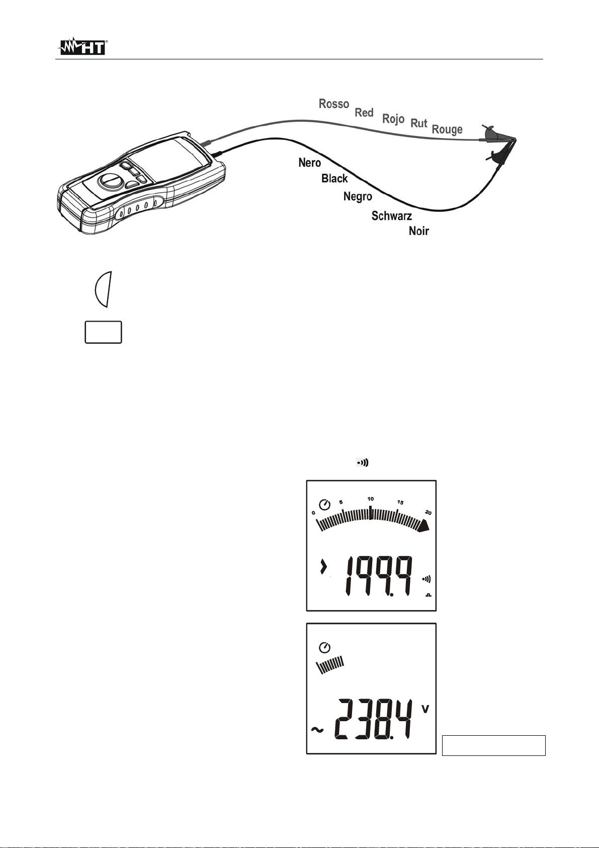
4.3. : AC VOLTAGE MEASUREMENT
CAUTION
The maximum input voltage is 550+10%V. Don’t try to measure higher
voltages to avoid risks of electrical shocks or serious damages to the
instrument.
Fig. 3: Connection of the instrument’s terminals during test
1.
2.
3. Insert the black and red cables in the corresponding input terminals of the instrument
4. If necessary, insert the croco clips on the test probes
Turn on the instrument
Press the arrow keys to select
5. Connect the cables to the desired points of the circuit under test as shown in Fig. 3.
The voltage value will be displayed
6. Example of display of AC voltage value
AC voltage value
4.3.1. Anomalous cases which may occur during measurements
1. The maximum input voltage is
550+10%V.
If the detected voltage value exceeds
605V RMS the instrument displays the
screen beside.
Disconnect immediately the instrument
from the circuit under test to avoid
electrical shocks and damages to the
instrument
EN - 7
Page 9

M70
4.4. : RESISTANCE MEASUREMENT AND CONTINUITY TEST
CAUTION
Before taking resistance measurements make sure that the circuit under test is
not powered and that eventual condensers are discharged. The measured
value is out of accuracy if an input voltage is present.
Fig. 4: Connection of the instrument’s terminals during test
1.
2.
Turn on the instrument
Press the arrow keys to select
3. Insert the black and red cables in the corresponding input terminals of the instrument
4. If the measuring cables being used
Resistance value
have not been calibrated, first calibrate
them as described in § 4.4.1
5. Position the test probes on the desired
points of the circuit under test (see Fig.
4)
6.
7.
GO
Example of display of resistance value. If such value is lower than 2 the instrument
Press GO to perform the
measurement
emits an acoustic signal
Press LOCK and GO together to perform the measurement in
8.
+
GO
continuous mode, the symbol LOCK is displayed. Press GO
another time to stop the continuous mode measurement
9. In lock mode the instrument emits an acoustic signal and the auto power off is
disabled
4.4.1. "ZERO" mode
1. Any addition or replacement of cables, extensions and croco clips nullify the previous
calibration and make necessary a new calibration before performing further
measurements. Therefore the instrument must be calibrated in the same conditions at
which it will operate during measurements
EN - 8
Page 10
M70
2. Short-circuit the cable ends with each other as shown in Fig. 5 making sure that the
metallic parts of test probes and crocodiles are in good touch
Fig. 5: Connection of the instrument’s terminals during calibration procedure
3.
4.
GO
MODE
PEAK
Press GO to perform the measurement
Press and hold ZERO key for 2s. The instrument resets the resistance of the
cables, the symbol ZERO is displayed
5. The measured value is stored by the instrument and used as offset (which means it’s
deducted from all continuity tests performed) until a new pressing of the ZERO key for
2s that voids the calibration
6. Each time the instrument is switched off or changing position of selector, the
calibrated value is lost
4.4.2. Anomalous cases which may occur during measurement
1. The full scale of the instrument is
199.9. If the resistance value is higher
than this value, or in case of open or
interrupted probes, the instrument
displays the screen beside.
2. If the voltage present at the terminals is
higher than 24V the instrument does not
perform the test. The screen beside is
displayed
EN - 9
Input voltage
Page 11

M70
4.5. Lo: CONTINUITY TEST ON EARTH, PROTECTIVE AND EQUALIZING
POTENTIAL CONDUCTORS
The measurement is performed with a test current higher than 200mA (R<5Ω) and open
circuit voltage ranging from 4 to 24V DC according IEC/EN 61557-4 and VDE 0413 part 4.
CAUTION
Before taking resistance measurements make sure that the circuit under test is
not powered and that eventual condensers are discharged. The measured
value is out of accuracy if an input voltage is present.
Fig. 6: Connection of the instrument’s terminals during Lo test
1.
2.
3. Insert the black and red cables in the corresponding input terminals of the instrument
4. If the measuring cables being used
Turn on the instrument
Press the arrow keys to select Lo
Resistance value
have not been calibrated, first calibrate
them as described in § 4.5.1
5. Position the test probes on the desired
points of the circuit under test (see Fig.
6)
6.
GO
Press GO to perform the
measurement
Press LOCK and GO together to perform the measurement in
7.
In lock mode the instrument emits an acoustic signal and the auto power off is
8.
disabled
+
GO
continuous mode, the symbol LOCK is displayed. Press GO
another time to stop the continuous mode measurement
EN - 10
Page 12

M70
4.5.1. "ZERO" mode
1. Any addition or replacement of cables, extensions and croco clips nullify the previous
calibration and make necessary a new calibration before performing further
measurements. Therefore the instrument must be calibrated in the same conditions at
which it will operate during measurements
2. Short-circuit the cable ends with each other as shown in Fig. 7 making sure that the
metallic parts of test probes and crocodiles are in good touch
Fig. 7: Connection of the instrument’s terminals during calibration procedure
3.
4.
GO
MODE
PEAK
Press GO to perform the measurement
Press and hold ZERO key for 2s. The instrument resets the resistance of the
cables, the symbol ZERO is displayed
5. The measured value is stored by the instrument and used as offset (which means it’s
deducted from all continuity tests performed) until a new pressing of the ZERO key for
2s that voids the calibration
6. Each time the instrument is switched off or changing position of selector, the
calibrated value is lost
4.5.2. Anomalous cases which may occur during Lo measurement
1. The full scale of the instrument is
19.99. If the resistance value is higher
than this value, or in case of open or
interrupted probes, the instrument
displays the screen beside
2. If the voltage present at the terminals is
higher than 24V the instrument does not
perform the test. The screen beside is
displayed
EN - 11
Input voltage
Page 13

M70
4.6. M: INSULATION RESISTANCE MEASUREMENT TEST VOLTAGE 250V,
500V, 1000V DC
The measurement is performed according to IEC/EN61557-2 and VDE 0413 part 1.
CAUTION
Before performing the insulation test make sure that the circuit under test is
not energized and all relative loads are disconnected.
The insulation measurement requires particolar care and attention to avoid
providing wrong test results and causing damages to third parties.
Before the insulation test prepare the plant adequately by disconnecting
everything must not be tested. During the insulation test continuously make
sure that the applied voltage is not accessible to third parties.
A measurement with a cable disconnected by mistake may provide a good
result also in presence of a faulty insulation. It’s necessary to take all
possibile cares to avoid that. Once prepared the plant and connected the
measuring cables, make sure that they are correctly connected. In case of
doubt, bifore performing an insulation test, perform a 0.2A measurement
by short-circuiting the cables under test at a point of the plant which is as
far as possibile from the measuring clips. Remove the short circuit before
performing the insulation test.
Fig. 8: Connection of the instrument’s terminals during M test
1.
2.
Turn on the instrument
Press the arrow keys to select M
3. Insert the black and red cables in the corresponding input terminals of the instrument,
If the cable length is not sufficient for the measurement extend the black one with an
adequately insulated cable, as its insulation is in parallel to the resistance to be
measured. It must be suspended and not laid to earth and all supports must be of
insulated material
4. If necessary insert the croco clips on the test probes
5. Disconnect the circuit or the part of plant under test from power and all eventual loads
6. Connect the instrument’s terminals to the end of the conductors on which the
insulation test must be performed (see Fig. 8)
7.
GO
Press GO to start the measurement for the set time (see par. 4.6.1). Press
GO to stop the measurement before the end of the set time
EN - 12
Page 14

M70
CAUTION
The message on the display means that the instrument is discharging
eventual capacitors. During this phase never disconnect nor touch test leads.
8. At the end of the test the instrument
automatically discharge eventual
capacitors and parasite capacitances
present among the conductors involved
in the measurement
9. At the end of the test a screen similar to
this is displayed
Nominal test voltage
value
Resistance value
10. If the resistance value is higher than the
full scale, a screen similar to this is
Nominal test voltage
value
displayed.
Note! An insulation value higher than
the full scale is an excellent insulation
value, generally much higher than the
minimum requirements prescribed by
standards
Press LOCK and GO together to perform the measurement in
11.
+
GO
continuous mode, the symbol LOCK is displayed. Press GO
another time to stop the continuous mode measurement
12. In lock mode the instrument emits an acoustic signal and the auto power off is
disabled
4.6.1. Measurement time setting mode
Press LOCK more than one
second, a screen similar to this
is displayed
Press the arrow keys to select
the desired time value
Setting values
between 2s an 60s
GO
Press GO to confirm the
selected value
4.6.2. Anomalous cases which may occur during M tests
If, during measurement, the input voltage
present at terminals is higher than 24V,
the instrument suspends the test.
A screen similar to this is displayed
showing the input voltage value.
EN - 13
Input voltage value
Page 15

M70
5. MAINTENANCE
5.1. GENERAL
This is a precision instrument. Strictly follow the instructions for use and storage reported
in this manual to avoid any possible damage or danger during use.
Do not use this tester under unfavorable conditions of high temperature or humidity. Do
not expose to direct sunlight.
Be sure to turn off the tester after use. If the instrument is not to be used for a long period
you are recommended to remove batteries to avoid leakages of battery liquid which may
damage its internal circuits.
5.2. BATTERY REPLACEMENT
When the low battery indication (refer to § 6.1.3) is displayed the batteries are to be
replaced.
CAUTION
Only skilled technicians can open the instrument and replace batteries. Before
removing batteries disconnect the test leads from the input terminals to avoid
electrical shocks.
1. Switch off the instrument
2. Remove test leads from the input terminals
3. Remove the battery compartment cover by using a screwdriver
4. Remove all batteries replacing them with new ones all of the same type (refer to §
6.1.3) respecting the polarity signs
5. Re-allocate the battery pack taking care that the part from which the black and red
wires come out is positioned backwards
6. If the battery pack is re-allocated in a wrong way, the battery compartment can not be
closed. In this case do not force the plastic parts, but re-position the battery pack
correctly before closing
7. Replace the battery compartment cover making a pressure to close it
8. Use the appropriate battery disposal methods for your area
5.3. CLEANING
Use a soft dry cloth to clean the instrument. Never use wet cloths, solvents, water, etc.
5.4. END OF LIFE
Caution: this symbol indicates that equipment and its accessories shall be
subject to a separate collection and correct disposal.
EN - 14
Page 16

M70
6. TECHNICAL SPECIFICATIONS
6.1. CHARACTERISTICS
Accuracy is indicated as [%reading + (digit number*resolution)] at 23°C±5°, RH <70%.
DC Voltage
Range Resolution Accuracy Input impedance Overload protection
0.1 600.0V
0.1mV
(0.5 rdg + 1 dgt) 3M
AC Voltage
Range Resolution
0.1 600.0V
Max crest factor: 2
0.1mV
Accuracy
(40 ÷ 500Hz)
Input impedance Overload protection
(0.8 rdg + 4 dgt) 3M
Resistance and Test Continuity
Range Resolution Accuracy Overload protection
0.0 199.9 0.1 (2.0% rdg + 3 dgt)
The buzzer sounds while measured resistance is lower than 2
605V AC max RMS per 1 minute
0.2A: Continuity test
Range Resolution Accuracy Overload protection
0.00 19.99 0.01 (2.0% rdg + 3 dgt)
Test current: >200mA DC up to 5 (measuring cables resistance included)
Test current: >10mA DC over 5 (measuring cables resistance included)
Open circuit voltage: 4 < V0 < 24V
M: Insulation resistance
Test voltage Range Resolution Accuracy Overload protection
0.001 0.100M 0.001M 10dgt
0.101 3.999M 0.001M
250V
4.00 39.99M 0.01M
40.0 399.9M 0.1M
400 1000M 1M
0.001 0.250M 0.001M 15dgt
0.251 3.999M 0.001M
500V
4.00 39.99M 0.01M
40.0 399.9M 0.1M
400 2000M 1M (5.0%rdg +5dgt)
0.001 0.250M 0.001M 15dgt
0.251 3.999M 0.001M
1000V
4.00 39.99M 0.01M
40.0 399.9M 0.1M
400 1000M 1M (3.0%rdg +5dgt)
1000 4000M 1M (5.0%rdg +10dgt)
Autorange
Open circuit voltage: <1.3 x V
Accuracy of nominal voltage: –0% +10%
Short circuit current: <15mA
Nominal testing current: 1mA @ 1K x V (1mA @ 500K)
0
(2.0%rdg+ 5dgt)
(5.0%rdg +5dgt)
(2.0%rdg +5dgt)
(2.0%rdg +5dgt)
605V AC max RMS
605V AC max RMS
605V max RMS
605V max RMS
EN - 15
Page 17

M70
6.1.1. Electrical
Conversion: Average value
Display refreshing rate: 2 times per second
6.1.2. Safety standards
The instrument complies with: IEC/EN61010-1, IEC/EN61557-1-2-4
Insulation: double insulation
Pollution level: 2
Max height of use: 2000m ; 6562ft
Measurement category: CAT III 550V (phase to earth)
CAT III 550V (phase to phase)
6.1.3. General specifications
Mechanical features
Dimensions (L x W x H): 240 x 100 x 45mm ; 9 x 4 x 2in
Weight (batteries included): 450g ; 16ounces
Power supply
Battery type: 4x1.5V batteries type AA LR6 AM3 MN 1500
Low battery indication: symbol " " is displayed
Battery life: Multimeter: About 50 hours
Lo: > 1000 tests @ 1
M 250V: > 1000 tests @ 480k
M 500V: > 1000 tests @ 480k
M 1000V: > 1000 tests @ 480k
Display
Features: 4 LCD with max. reading 9999 counts + symbol
and decimal point
6.2. ENVIRONMENT
6.2.1. Environmental conditions
Reference temperature: 23°C ± 5°C ; 73°F ± 41°F
Working temperature: 0°C ÷ 40°C ; 32°F ÷ 104°F
Relative humidity allowed: <70% RH
Storage temperature: -10° ÷ 60° C ; 14°F ÷ 140°F
Storage humidity: <70% RH
This instrument complies with the requirements of the European Low Voltage
Directive 2006/95/CE (LVD) and EMC Directive 2004/108/CE
6.3. ACCESSORIES
6.3.1. Standard accessories
Set of 2 R/B cables, 1.5m + 2 R/B alligator clips + 1 R test lead
Batteries
Carrying bag
Certificate of test
User manual
EN - 16
Page 18

M70
7. SERVICE
7.1. WARRANTY CONDITIONS
This instrument is guaranteed against material or production defects, in accordance with
our general sales conditions. During the warranty period the manufacturer reserves the
right to decide either to repair or replace the product.
Should you need for any reason to return back the instrument for repair or replacement
take prior agreements with the local distributor from whom you bought it. Do not forget to
enclose a report describing the reasons for returning (detected fault). Use only original
packaging. Any damage occurred in transit due to non original packaging will be charged
anyhow to the customer.
The manufacturer will not be responsible for any damage to persons or things.
The warranty doesn’t apply to:
Accessories and batteries (not covered by warranty).
Repairs made necessary by improper use (including adaptation to particular
applications not foreseen in the instructions manual) or improper combination with
incompatible accessories or equipment.
Repairs made necessary by improper shipping material causing damages in transit.
Repairs made necessary by previous attempts for repair carried out by non skilled or
unauthorized personnel.
Modifications to the equipment without explicit authorization from our technical
department.
Adaptation to a particular application not provided for by the definition of the equipment
or by the instruction manual.
The contents of this manual may not be reproduced in any form whatsoever without the
manufacturer’s authorization.
Our products are patented and our logotypes registered. We reserve the right to
modify specifications and prices in view of technological improvements or
developments which might be necessary.
7.2. AFTER-SALE SERVICE
Shouldn’t the instrument work properly, before contacting your distributor make sure that
batteries are correctly installed and working, check the test leads and replace them if
necessary. Make sure that your operating procedure corresponds to the one described in
this manual.
Should you need for any reason to return back the instrument for repair or replacement
take prior agreements with the local distributor from whom you bought it. Do not forget to
enclose a report describing the reasons for returning (detected fault). Use only original
packaging. Any damage occurred in transit due to non original packaging will be charged
anyhow to the customer.
The manufacturer will not be responsible for any damage to persons or things.
EN - 17
 Loading...