

Page 1

ENGLISH
User manual
Copyright HT ITALIA 2013 Release EN 1.00 - 02/12/2013
Page 2

iDM70
Table of contents
1. PRECAUTION AND SAFETY MEASURES………………….2
2. PREPARATION FOR USE……………………………………. 4
2.1. Initial checks ................................................................................ 4
2.2. Instrument power supply ............................................................. 4
2.3. Storage ........................................................................................ 4
3. INSTRUMENT DESCRIPTION……………………………….. 5
3.1. Description of the controls ........................................................... 5
3.2. Display description ...................................................................... 6
3.3. General description of the instrument ......................................... 7
4. OPERATING INSTRUCTIONS……………………………….. 8
4.1. Initial operations and settings ...................................................... 8
4.2. Setting of measuring reference ................................................... 8
4.3. Distance measurement ............................................................. 10
4.4. Continuous distance measurement ........................................... 10
4.5. Additions / subtractions of measures ........................................ 11
4.6. Area measurement .................................................................... 12
4.7. Volume measurement ............................................................... 13
4.8. Indirect 2-point measurement .................................................... 14
4.9. Indirect 3-point measurement .................................................... 15
4.10. Measurement of tilt and distance .............................................. 17
4.11. Operations with the memory ..................................................... 17
4.12. Distance measurement with thresholds .................................... 18
4.13. Distance measurement with timer ............................................. 19
4.14. Bluetooth connection ................................................................. 19
5. MEASURING CONDITIONS………………………………… 20
6. REPLACING INTERNAL BATTERIES……………………... 20
7. ERROR MESSAGES ON THE DISPLAY………………….. 21
8. TECHNICAL SPECIFICATIONS……………………………. 22
8.1. Technical characteristics ........................................................... 22
8.2. Reference standards ................................................................. 22
9. ACCESSORIES PROVIDED………………………………... 22
10.SERVICE………………………………………………………. 23
10.1. Warranty conditions ................................................................... 23
EN - 1
Page 3
iDM70
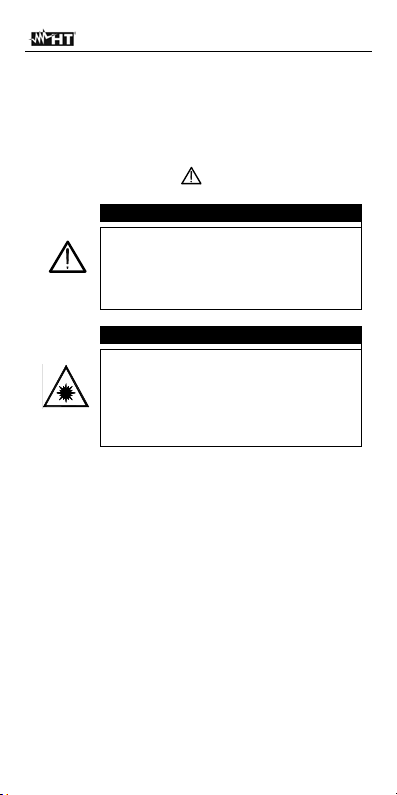
1. PRECAUTION AND SAFETY MEASURES
The instrument has been designed in compliance with
the directives relevant to electronic measuring
instruments. For your safety and in order to prevent
damaging the instrument, please carefully follow the
procedures described in this manual and read all notes
preceded by the symbol
In case the instrument is used in a way
different from the one described in this
user manual, this could result in a
failure of the protections the instrument
is provided with.
When this symbol is displayed, the
instrument is not able to emit a laser
pointer. Always prevent the laser
from radiating to your eyes, in order
to prevent any injury. Class II laser
device compliant with EN 60825-1
with the utmost attention.
CAUTION
CAUTION
EN - 2
Page 4

iDM70
In this manual, and on the instrument, the following
symbols are used:
Warning: observe the instructions given in
this manual; improper use could damage
the instrument or its components.
Warning: always prevent the
laser from radiating to your eyes,
in order to prevent any injury.
The instrument and its
accessories must be collected
separately and correctly
disposed of in the appropriate
containers.
EN - 3
Page 5

iDM70
2. PREPARATION FOR USE
2.1. Initial checks
Before shipping, the instrument has been checked
from an electric as well as mechanical point of view.
All possible precautions have been taken so that it is
delivered undamaged.
However, we recommend generally checking the
instrument in order to detect possible damage suffered
during transport. In case anomalies are found,
immediately contact the forwarding agent.
We also recommend checking that the packaging
contains all components indicated in § 9. In case of
discrepancy, please contact the Dealer.
In case the instrument should be returned, please
follow the instructions given in § 10.1
2.2. Instrument power supply
The instrument is supplied with two 1.5V AA LR06
batteries, included in the package. Battery life equals
about 8000 measurements. The “
flashes on the display when the battery is flat. Replace
the battery by following the instructions given in § 6
2.3. Storage
In order to guarantee precise measurement, after a
long storage time under extreme environmental
conditions, wait for the instrument to come back to
normal condition (see § 8.1). Given its simplicity, the
instrument does not need any periodic calibration
EN - 4
“ symbol
Page 6
iDM70
3. INSTRUMENT DESCRIPTION
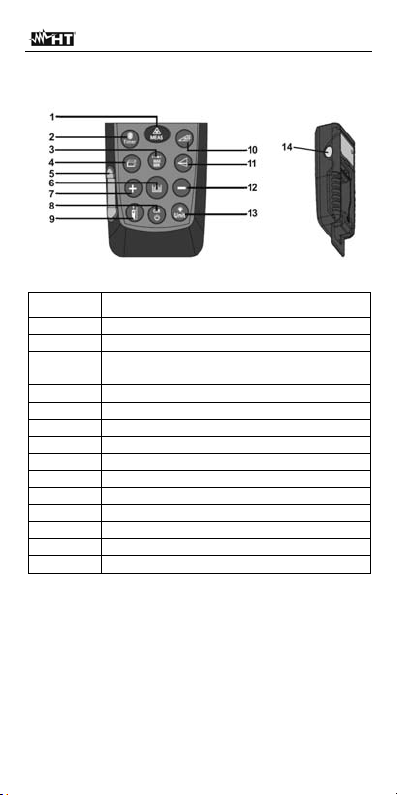
3.1. Description of the controls
Fig. 1: Instrument description
Caption Description
1 ON/MEAS key
2 Timer/Bluetooth key
Key for single/continuous distance
3
measurement
4 Area/Volume key
5 Air bubble level
6 Key for saving measurement results
7 “+” key
8 OFF/CLR key
9 Reference setting key
10 Tilt/Dimension key
11 Key for indirect distance measurement
12 “-” key
13 Backlight/Measuring unit key
14 ON/MEAS key
EN - 5
Page 7
iDM70
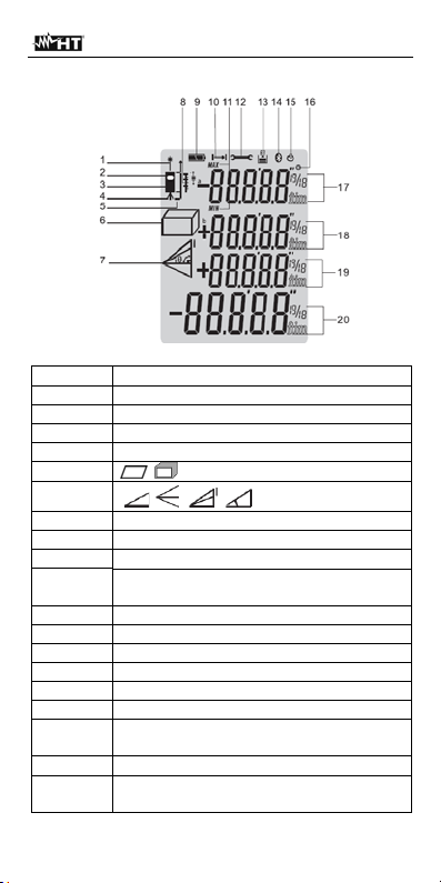
3.2. Display description
Fig. 2: Description of the symbols at display
Caption Description
1 Active laser
2/3 Front/rear reference
4 Tripod reference
5 Instrument level + stand reference
6
7
, area, volume measurement
, , , indirect measures/tilt
8 Distance measurement with dimensions
9 Battery charge level
10 Distance measurement
Max and Min measurements in
11
continuous mode
12 Instrument error message
13 Memory for partial data saving
14 Bluetooth symbol
15 Active timer symbol
16 Tilt symbol
17 First measurement partial value display
Second measurement partial value
18
display
19 Third measurement partial value display
Last measurement value display and
20
result
EN - 6
Page 8

iDM70
3.3. General description of the instr ument
iDM70 has the following functions:
Direct measurement of distances expressed in
m/in/ft and ft+in
Measurement of area and volume
Indirect 2- and 3-point distance measurement
(Pitagora)
Distance measurement in continuous mode
Sum/difference of measured distance values
Measurement of tilt angle
Distance measurement with dimensions
Setting of measuring reference
Setting of timer for measurements
Connection to Bluetooth devices, iPhone, iPad,
iPod touch, Android via Meterbox APP
Activation of the laser pointer for measurement
Integrated air bubble level
Partial operations with use of internal memory (max
20 locations)
Display backlight
Activation of buzzer upon key pressing
The model is provided with a wide display, a
comfortable membrane keyboard with 13 function keys
and a class II laser pointer for a precise definition of
the application point.
The measurement of distance between two points
(with a measuring range from 5cm to 70m) is carried
out by reflection of the laser light from the surface hit
to the receiving sensor located in the upper part of the
instrument.
Measurement can be influenced by the brightness of
the environment in which it is performed and by the
type of surface hit by the laser pointer.
EN - 7
Page 9

iDM70
4. OPERATING INSTRUCTIONS
4.1. Ini tia l operations and settings
Press the
the laser pointer. Press and hold the
switch off the instrument.
Press the key
shown on the display.
Press the
Press the keys
delete the temporary memory's content. The value
“00” is shown on the display.
Press the
backlight of the disp lay.
Press and hold the
for setting distance measuring units. Cyclically press
the key to select the options: “m”, “ft”, “in” and
“ft+in”
4.2. Setting of measuring reference
In order to perform correct measurements, it is
important to define beforehand the measuring
reference on the instrument by pressing the
Possible options are:
Top measurement is carried out by the upper
part of the instrument.
Bottom measurement is carried out by the lower
part of the instrument and therefore also the whole
instrument length is considered (default condition)
key to switch on the instrument and
key to
to clear (CLR) the last datum
key to see the saved distance values.
and at the same time to
key to activate/deactivate the
key to activate the section
key.
“Bottom” reference “Top” reference
EN - 8
Page 10

iDM70
Tripod (see Fig. 2 – Pos. 4) Press and hold the
key for 2s. Measurement is carried out from the
hole where the tripod is inserted
Instrument + stand level The instrument is
provided with a stand which can be opened to
comfortably rest the unit on horizontal surfaces Fig.
3). With the stand at 90°, delicately move it to the
right and open it completely (see Fig. 4). In this
position, by resting the instrument on an angle or
step, it is automatically configured with the level
shown in Fig. 2 – Pos. 5). Move it delicately to the
right and turn the stand to close it on the instrument
Fig. 3: Distance measurement on sides and angles
Fig. 4: Stand opening for measurements on angles
EN - 9
Page 11

iDM70
4.3. Distance measurement
1. W ith the instrument in stand-by, press the
or the side MEAS key to activate the laser pointer
2. Use the laser pointer to precisely determine the
measuring point, keeping the instrument as
perpendicular as possible with respect to the
surface of the object to be measured
3. Press the
key or the side MEAS key again to
measure. The value will be displayed in the
selected measuring unit (see § 4.1) and the result
will be automatically saved in the memory area.
4.4. Continuous di stance measurement
Upon start-up, the instrument is set to normal mode or
measuring the distance between 2 points. Continuous
measuring mode allows for a dynamic management of
the distance and the display of the maximum and
minimum measurement values.
1. With the instrument in stand-by, press the key
to select the desired type of reference (see § 4.2)
2. Press and hold the
key to activate the
continuous measuring mode. The indications “Min”
and “Max” are shown on partial displays
3. Press the
or OFF/CLR key to stop continuous
measurement. The function is automatically
stopped after approx. 50s
4. The minimum and maximum value of distance are
shown in the partial displays while continuous
measurement is shown dynamically when moving
the instrument (see Fig. 5) on the resulting display
key
Fig. 5: Examples of continuous distance measures
5. Press the key to exit the continuous measuring
mode and go back to normal mode
EN - 10
Page 12

iDM70
In Fig. 6 some applications of continuous
measurement are indicated
Fig. 6: Applications of continuous measurement
4.5. Additions / subtractions of measures
When measuring distance, it is possible to use the
following functions:
Key Function
The subsequent measure is added to
the previous one. The result of the sum
is shown on the resulting display.
The subsequent measure is subtracted
from the previous one. The result of the
difference is shown on the resulting
display.
EN - 11
Page 13

iDM70
4.6. Area measurement
This measurement allows calculating the area of
surfaces expressed in m
1. With the instrument in stand-by, press the key
or the side MEAS key to select the desired type of
reference (see § 4.2)
2. Press the
measuring section. The symbol “
the display with side “1” flashing
3. Press the
perform the first measurement (length) of the
surface concerned (see Fig. 7). The corresponding
value appears on the first partial display. The
symbol “
flashing
4. Press the
perform the second measurement (width) of the
surface concerned (see Fig. 7). The corresponding
value appears on the second partial display, while
the (up-to-date) total value of the area appears on
the resulting display
5. Measuring result is automatically saved in the
instrument's memory
2
, in2 or ft2
key to enter the Area/Volume
“ appears on
key or the side MEAS key to
“ appears on the display with side “2”
key or the side MEAS key to
Fig. 7: Example of area measurement
EN - 12
Page 14

iDM70
4.7. Volume measurement
This measurement allows calculating the volume of
solids expressed in m
1. With the instrument in stand-by, press the
to select the desired type of reference (see § 4.2)
2. Press the
measuring section. The symbol “
the display with side “higher” flashing
3. Press the
perform the first measurement (length) of the
surface (see Fig. 8). The corresponding value
appears on the first partial display. The symbol “
appears on the display with side “1” flashing
4. Press the
perform the second measurement (width) of the
surface (see Fig. 8). The corresponding value
appears on the second partial display. The value of
the corresponding area is shown on the resulting
display. The symbol “
with side “2” flashing
5. Press the
perform the third measurement (height) (see Fig.
8). The total value of volume is shown on the main
resulting display
6. Measuring result is automatically saved in the
instrument's memory
3
, in2 or ft3
key
key twice to enter the Area/Volume
“ appears on
key or the side MEAS key to
key or the side MEAS key to
“ appears on the display
key or the side MEAS key again to
“
Fig. 8: Example of volume measurement
EN - 13
Page 15

iDM70
4.8. Indirect 2-point measurement
Indirect measurement allows precisely evaluating a
distance between two points on a vertical wall (height)
exploiting the mathematical principle of the
Pythagorean theorem. For accurate measures we
recommend using a tripod.
1. With the instrument in stand-by, press the
to select the desired type of reference (see § 4.2)
2. Press the
measuring section. The symbol “
key to enter the indirect 2-point
“ appears on the
display with side “1” flashing
3. Position the instrument in the highest point (1) of
measurement (see Fig. 9) and press the
or the side MEAS key to measure. The result
appears on the first partial display. The symbol “
appears on the display with side “2” flashing
4. Position the instrument as horizontally as possible
(2) (see Fig. 9) and press the
key or the side
MEAS key to measure. The result appears on the
second partial display
5. The final value of the result (obtained as
is shown on the resulting display
6. Measuring result is automatically saved in the
instrument's memory
key
key
22
)2()1(
“
)
Fig. 9: Indirect 2-point measurement
EN - 14
Page 16

iDM70
4.9. Indirect 3-point measurement
The instrument performs indirect 3-point measurement
in two different modes, described below.
Mode “
1. With the instrument in stand-by, press the key
2. Press the
3. Position the instrument in the lowest point (1) of
4. Position the instrument as horizontally as possible
5. Position the instrument in the highest point (3) of
6. The final value of the result obtained with the
7. Measuring result is automatically saved in the
”
to select the desired type of reference (see § 4.2)
key twice to enter the indirect 3-point
measuring section. The symbol “
“ appears on the
display with side “1” flashing
measurement (see Fig. 10) and press the
key
or the side MEAS key. The result appears on the
first partial display. The symbol “
“ appears on the
display with side “2” flashing
(2) and press the
key or the side MEAS key to
measure. The result appears on the second partial
display. The symbol “
“ appears on the display
with side “3” flashing
measurement (see Fig. 10) and press the
key
or the side MEAS key to measure. The result
appears on the second partial display
combination of previous measures is shown on the
resulting display
instrument's memory
Fig. 10: Misura Indiretta a 3 punti – Modo 1
EN - 15
Page 17

iDM70
Mode “
1. With the instrument in stand-by, press the key to
2. Press the
3. Position the instrument in the lowest point (1) of
4. Position the instrument as horizontally as possible
5. Position the instrument in the highest point (3) of
6. The final value of the result obtained with the
7. Measuring result is automatically saved in the
”
select the desired type of reference (see § 4.2)
key three times to enter the indirect 3-
point measuring section. The symbol “
“ appears
on the display with side “1” flashing
measurement (see Fig. 11 ) and press the
key
or the side MEAS key. The result appears on the
first partial display. The symbol “
“ appears on the
display with side “2” flashing
(2) (see Fig. 11) and press the
key or the side
MEAS key to measure. The result appears on the
second partial display. The symbol “
“ appears on
the display with side “3” flashing
measurement (see Fig. 11) and press the
key
or the side MEAS key to measure. The result
appears on the second partial display
combination of previous measures (see dashed line
in Fig. 11) is shown on the resulting display
instrument's memory
Fig. 11: Indirect 3-point measurement – Mode 2
EN - 16
Page 18

iDM70
4.10. Measurement of tilt and distance
This measurement allows for an evaluation of the tilt
with respect to the horizontal by means of an internal
sensor and of the distance between two points through
trigonometric calculation. For accurate measures we
recommend using a tripod
1. With the instrument in stand-by, press the
select the desired type of reference (see § 4.2)
2. Press the
key to enter the indirect 3-point
measuring section. The symbol “
the display with side “1” flashing
3. Position the instrument in the point (1)
corresponding to the value of the desired measuring
angle ““ (varying between ±65° with transversal tilt
not higher than ±10°) shown on the first display and
press the
key or the side MEAS key (see Fig.
12)
4. The value of distance “1” is shown on the resulting
display. The value of distance “a” is shown on the
third display, calculated as: a = (1)* cos. The value
of distance “b” is shown on the second display,
calculated as: b = (1)* sen (see Fig. 12)
5. Measuring result is automatically saved in the
instrument's memory
key to
“ appears on
Fig. 12: Distance test with trigonometric calculation
4.11. Operations with the memory
The instrument is provided with a memory section in
which it is possible to recall measuring results. It is
possible to save up to 20 measurements, shown in
reverse order.
Use the keys
Press the keys
or for internal navigation.
and at the same time to
delete the memory's content
EN - 17
Page 19

iDM70
4.12. Distance measurement with thresholds
The instrument measures distance continuously by
fixing two thresholds (a) and (b) in order to precisely
define the position of objects along a radial line
1. With the instrument in stand-by, press the
select the type of reference (see § 4.2)
2. Press and hold the
the measuring section with dimensions. A flashing
indication of the size (a) appears on the display
3. Use the
between 5cm and 60m. Keep the keys pressed to
carry out a quick setting of the values. Confirm the
value of s ize (a) with key
the size (b) appears on the display
4. Use the
between 5cm and 60m. Keep the keys pressed to
carry out a quick setting of the values. Confirm the
value of size (b) with key
the dimension (a) appears on the display
5. Press the
measure. The value of distance in real time is shown
on the resulting display
6. Slowly move the instrument along the radial line,
observing the measured value (see Fig. 13). The
instrument shows the arrows or to indicate the
direction in which to proceed and starts sounding at
a distance of 0,1m from the thresholds (a) and (b)
fixed, giving out a continuous sound when threshold
is reached. Measurement has a duration of approx.
1 minute and may be stopped by pressing the
or
or keys to set the value of size (a)
or keys to set the value of size (b)
key
key for 2 seconds to enter
. A flashing indication of
. A flashing indication of
key or the side MEAS key to
key to
Fig. 13: Distance measurement with thresholds
EN - 18
Page 20

iDM70
4.13. Distance measurement with timer
The instrument allows measuring distances with timer
setting (max. 60s).
1. With the instrument in stand-by, press the
select the type of reference (see § 4.2)
2. Press the
default duration of 5s, or press and hold the
for a quick setti ng of the desired value, or use t he
or keys to set the desired value with 1s scan
3. Press the
few seconds after setting the timer for measurement
to start. The instrument activates a count down
4. In the last 2 seconds the instrument sounds loud.
Upon timer end the value is shown on the resulting
display
5. Measuring result is automatically saved in the
instrument's memory
4.14. Bluetooth connection
The instrument allows for the connection to mobile
devices such as iPhone, iPad, iPod, Android via
Bluetooth connection, provided you install the
HTLaserMeter APP on the devices. To activate
connection, proceed as follows:
1. Press and hold the
symbol “Bluetooth” appears on the display
2. Connect the instrument to the mobile device via the
HTLaserMeter APP (see the relevant user manual)
3. Upon the first connection between the instrument
and the device, a message requesting a Pin may be
shown by the device. In this case, please enter code
“0000”
4. Press and hold the
the Bluetooth function or switch off the inst rum ent
key to enter the Timer mode with a
key or the side MEAS key or wait a
key for 2 seconds. The
key for two seconds to quit
EN - 19
key to
key
Page 21

iDM70
5. MEASURING CONDITIONS
Measuring range
The instrument's measuring range is 70m. At night,
under poor visibility conditions or if the surface to be
measured is in shadow, the measuring range can be
reduced. To prevent this, carry out measurements
during the day or use luminous plates when the object
to be measured has poor reflecting properties.
Object surface
The instrument can give errors when measurements
are carried out on colourless liquids (e.g. water),
transparent glass, polystyrene, very polished or halfpermeable surfaces because of the deviation of the
laser beam. Non-reflecting surfaces may cause delays
when measuring.
Maintenance
Do not immerse the instrument in water. To clean the
instrument, use a soft cloth moist with neutral
detergent
6. REPLACING INTERNAL BATTERIES
The instrument is supplied by 2x1.5V AA LR06 alkaline
batteries. When the symbol “
display, it is necessary to replace the batteries.
Proceed as follows:
1. Slide the battery compartment cover to the right and
remove it (see Fig. 14)
2. Remove the batteries and insert the same number
of batteries of the same type, respecting the correct
polarity. Only use alkaline batteries
3. Restore the battery compartment cover into position
by sliding it to the left to fasten it again
“ flashes on the
Fig. 14: Replacement of the internal battery
EN - 20
Page 22

iDM70
7. ERROR MESSAGES ON THE DISPLAY
Code Description Solution
204 Calculation error
Weak signal reflection,
measuring time too
208
long, distance > 70m or
<5cm
Too intense reflection of
209
the signal
252 Temperature too high
253 Temperature too low
255 Hardware error
Press and repeat
procedure
Carry out measurement
on an appropriate
surface
Carry out measurement
on a less reflective
surface
Let the instrument cool
down
Let the instrument heat
up
Turn off the instrument
and turn it on again
several times. Contact
Customer Service if the
message is displayed
again.
EN - 21
Page 23

iDM70
8. TECHNICAL SPECIFICATIONS
8.1. Technical characteristics
Measuring range (*):
0.05 70m (0.2in229ft)
Resolution: 0.001m (0.001ft)
Accuracy (@10m):
Tilt measuring range:
1.5mm (**)
65° (side <10°)
Laser pointer: 635nm, Class II, <1mW
Display:
LCD, 5 digits with
backlight
Power supply: 2x1.5V type AA LR06
Duration: up to 8000 measurements
Operating temperature:
Storage temperature:
0°C 40°C
-10° 60°C
Auto power off: 30s (laser), 3min (iDM70)
Size (LxWxH): 135 x 53 x 30mm
Weight (batteries
included):
160g
Mechanical protection: IP54
Bluetooth: 3.0 EDR, range 10m
(*) Measuring range and accuracy depend on the correct reflection of the laser beam
from the surface of the object to the instrument's sensor and on the brightness of the
environment in which tests are performed.
(**) Under favourable conditions (optimum object surface, room temperature). Under
unfavourable conditions (intense sunshine, poor reflective properties of the object,
high variations in temperature) the resolution in measurements >10m may be higher
by ±0.15mm/m (±0.0018in/ft)
8.2. Reference standards
IEC/EN61326-1 :2006
IEC/EN61326-2-2 :2006
EMC:
IEC/EN61326-1 :2005
IEC/EN61326-2-2 :2005
2004/108/EC EMC directive
Laser : IEC/EN60825-1
9. ACCESSORIES PROVIDED
Carrying bag
Batteries
User manual of the instrument
User manual of HTLaserMeter APP
EN - 22
Page 24

iDM70
10. SERVICE
10.1. Warranty conditions
This instrument is warranted against any material or
manufacturing defect, in compliance with the general
sales conditions. During the warranty period, the
manufacturer reserves the right to repair or replace the
product.
Should the instrument be returned to the After-sales
Service or to a Dealer, transport will be at the
Customers charge. A report will always be enclosed to
a shipment, stating the reasons for the products return.
The manufacturer declines any responsibility for injury
to people or damage to property.
The warranty shall not apply in the following cases:
Repair and/or replacement of accessories and
battery (not covered by warranty)
Repairs that may become necessary as a
consequence of improper use.
Repairs that may become necessary as a
consequence of improper packaging.
Repairs which may become necessary as a
consequence of interventions performed by
unauthorized personnel.
Modifications to the instrument performed without
the manufacturers explicit authorization.
Use not provided for in the instruments
specifications or in the instruction manual.
The content of this manual cannot be reproduced in
any form without the manufacturer’s authorization
EN - 23
 Loading...