

Page 1

HT950N
Panel meter for temperature control
User’s manual
Copyright HT-ITALIA 2003 Release EN 1.04 - 13/10/04
Page 2

HT950N
Index:
1. SAFETY PRECAUTIONS AND PROCEDURES ...................................................................... 3
1.1. Preliminary ............................................................................................................ 3
1.2. During use ............................................................................................................. 3
2. GENERAL DESCRIPTION ....................................................................................................... 4
3. PREPARATION TO USE .......................................................................................................... 4
3.1. Initial ...................................................................................................................... 4
3.2. Power supply ......................................................................................................... 4
3.3. Calibration ............................................................................................................. 4
3.4. Storage .................................................................................................................. 4
4. OPERATING INSTRUCTIONS ................................................................................................. 5
4.1. Description front panel ........................................................................................... 5
4.2. Description of function keys ................................................................................... 6
4.3. Description of back panel ...................................................................................... 7
5. OPERATIVE INSTRUCTIONS .................................................................................................. 8
5.1. Installation ............................................................................................................. 8
5.2. Electrical connections ............................................................................................ 8
5.2.1. Power supply circuit .......................................................................................... 9
5.2.2. Temperature probes ....................................................................................... 10
5.2.3. CONTR output circuit ...................................................................................... 10
5.2.4. T1 output alarm circuit .................................................................................... 11
5.2.5. T2 output alarm circuit .................................................................................... 11
5.3. Messages on Power-ON ..................................................................................... 11
5.4. Setup of alarm thresholds .................................................................................... 12
5.4.1. Example of HT950N meter setup .................................................................... 13
5.5. Clear of recorded max temperature value ........................................................... 13
5.6. Setup of input probes number ............................................................................. 14
6. PREVENTIVE MAINTENANCE .............................................................................................. 14
6.1. General information ............................................................................................. 14
6.2. Cleaning .............................................................................................................. 14
7. TECHNICAL SPECIFICATIONS ............................................................................................. 15
7.1. Technical Characteristics .................................................................................... 15
7.1.1. Inputs characteristics ...................................................................................... 15
7.1.2. Output characteristics ..................................................................................... 15
7.1.3. Safety characteristics ...................................................................................... 15
7.1.4. General characteristics ................................................................................... 15
7.2. Environmental conditions .................................................................................... 15
7.2.1. Climatic conditions .......................................................................................... 15
7.2.2. EMC ................................................................................................................ 15
7.3. Accessories ......................................................................................................... 15
7.3.1. Standard accessories ..................................................................................... 15
8. SERVICE ................................................................................................................................ 16
8.1. Warranty conditions ............................................................................................. 16
8.2. Service ................................................................................................................ 16
EN - 1
Page 3

HT950N
1. SAFETY PRECAUTIONS AND PROCEDURES
This meter is designed in conformity to EN61010 standards relating to electronic
measuring instruments. For your own safety and that of the apparatus, you must follow the
procedures described in this instruction manual and specially read all the notes preceded
by the symbol carefully.
Strictly keep to the following instructions before and during measurements:
Do not install the meter in environments with explosive gas, fuels or dust.
Do not install in case of unusual conditions of the instrument such as deformation,
breakage, leakage of substances, absence of display reading etc.
The following symbols are used in this manual:
WARNING
No compliance with the Warnings and/or Instructions may damage the
apparatus and/or its components or injure the operator.
1.1. PRELIMINARY
Use the meter only as specified in this manual; otherwise, the protection provided by
the meter may be impaired.
Only the accessories supplied with the instrument guarantee compliance with the
safety standards. They must be in good conditions and must be replaced, if necessary,
with identical models.
Do not effect measurements beyond the limits specified in this manual.
Take care that indications on display its according with selected function.
1.2. DURING USE
Carefully read the following recommendations and instructions:
WARNING
No compliance with the Warnings and/or Instructions may damage the
apparatus and/or its components or injure the operator.
Safety protection for the meter maybe damaged.
Use the meter and the temperature probes only within the ranges specified in the
chapter 7.1.1 of manual.
Do not perform any measurement on materials under voltage. This could damage the
instrument.
EN - 3
Page 4

HT950N
2. GENERAL DESCRIPTION
Dear Customer, we thank you for your patronage. The HT950N meter you have just
purchased will grant you accurate and reliable measurements, on protection of MV
transformer, provided that it is used according to the present manual’s instructions.
The HT950N model it was been designed with high quality electrical components and,
during test verify, it’s subject to BURN-IN test to eliminate any internal bugs due to rapid
death rate of components.
The HT950N meter presents the following features:
1 up to 4 input temperature signals, selectable by key, from same number of thermo
sensitivity elements Pt100 DIN type with three wires.
Measurement range from 0° to 200°C.
Automatic compensation of 3-wire cable resistance.
Setting of two alarm thresholds temperature T2 and T1, with T2>T1, programmable on
all measurement range, with activation of the same number of output relays.
Setting of two alarm thresholds temperature UA and UF, with UF<UA with activation of
an output relay. These thresholds can be used to activate a possible forced ventilation
system or a parallel device.
3. PREPARATION TO USE
3.1. INITIAL
The instrument has been checked from every point of view before shipment. Every care
has been taken to make sure that the instrument reaches you in perfect conditions.
However, it’s advisable to make a rapid check in order to detect eventual damages, which
may have occurred in transit. Should this be the case, enter immediately the usual claims
with the carrier. Make sure that all the accessories listed in paragraph 7.3.1are contained
in the package. In case of discrepancies contact the dealer.
In case of returning of the tester, please keep to the instructions given in chapter 8.
3.2. POWER SUPPLY
The instrument can be supplied with a voltage between 24 and 240 V AC (50/60 Hz) or DC
voltage.
3.3. CALIBRATION
The instrument complies with the technical features listed in this manual.
3.4. STORAGE
In order to guarantee the accuracy of the measurements, after a period of storage in
extreme environmental condition, wait for the necessary time so that the instrument
returns to normal measuring conditions (see paragraph 7.2.1).
EN - 4
Page 5

HT950N
4. OPERATING INSTRUCTIONS
4.1. DESCRIPTION FRONT PANEL
LEGEND:
1. Principal Display
2. PARAmeters Display
3. SET Display
4. Function keys
HT950N
Controller
Fig. 1: Instrument description, frontal view
CONTROL Led
The light on of this Led mean that temperature of one of four inputs is over the setting UA
threshold value and the CONTR output relay is closed. This can active the start of forced
ventilation system or a parallel device. The Led light off only when temperature decrease
under UF threshold value and the CONTR relay is open. This can disconnect the forced
ventilation system or a parallel device (see Fig. 9 ).
PT100 Led
This Led shows that at least one of four controlled input probes (2U, 2V, 2W or 1F Led is
blinking) is shorted or opened. In this case an alarm condition is activated by HT950N and
relay T1 is opened.
2U-2V-2W-1F Led
These Leds shows, for each of four columns:
With fixed light means the temperature column you can read on principal display.
With blinking light, together Pt100 light on, means problems at the correspondent
thermoresistance.
T1 Led
This Led have the following functions:
When is light on its shows that temperature of one of four probes is over T1 threshold
set on HT950N and correspondent relay have activated pre-alarm condition (see Fig.
9).
When is light off, with Pt100 Led fixed light on, its shows one of following conditions:
1. Disconnection of one of four input Pt100 (with correspondent blinking led).
2. One Pt100 is shorted (like point 1.).
3. No one power supply at meter.
EN - 5
Page 6

HT950N
T2 Led
This Led shows that measured temperature by one of four probes is over T2 alarm
threshold set on HT950N and correspondent relay is activated. This means transformer
turn off (see Fig. 9).
T.MAX Led
This Led is light on when you press T.MAX key and show the maximum temperature
recording by HT950N during all measured period. SET display shows the temperature
value and PARA display shows the column (C1=2U, C2=2V, C3=2W, C4=1F) of
correspondent maximum value.
ERROR Led
This Led is light on if there is an error on setting threshold temperature values. In particular
for T2<T1 or UA<UF wrong set conditions.
Principal Display
This display always show the real time temperature of the hot column.
SET Display
This display shows the following temperatures:
T2 temperature of transformer turn off during threshold setting.
T1 temperature of pre-alarm during threshold setting.
UA temperature of forced ventilation activation during threshold setting.
UF temperature of forced ventilation disable during threshold setting.
Maximum temperature recording by HT950N during measurements.
Temperature of four columns C1, C2, C3, C4.
PARA Display
This display show the control parameter (T2, T1, UF, UA) and the columns symbol (C1,
C2, C3, C4).
4.2. DESCRIPTION OF FUNCTION KEYS
PARA key
This key can activate the setting of thresholds temperature. Refer to chapter 5.4 for any
details.
ALT.T. key
Press this key the HT950N meter shows real temperatures on the four columns. PARA
display shows the columns names C1=2U, C2=2V, C3=2W, C4=1F and SET display
shows the correspondent temperature values. These displays light off in the following
three ways: press ENT. Key, press ALT.T. key when C4 column appair or automatically
after about 20 sec. From last operation.
TEST key
Press this key HT950N execute a functionally test on verify the light on of all Led and
displays on the front panel.
EN - 6
Page 7

HT950N
AAA
T.MAX key
Press this key the meter show at PARA display the column symbol (C1, C2, C3, C4) which
have the maximum temperature value during all measure period. SET display show
instead the value of recording temperature. T.MAX Led is light on during operation.
After about 20 sec. from pressing of T.MAX key PARA and SET displays automatically
light off.
T.MAX key is also used for reset temperature maximum value (see chapter 5.4. for
details).
WARNING
T.MAX is automatically update only with higher values and remain saved
inside HT950N also in switch off condition.
T.MAX key don’t execute any operation if meter is inside setup parameters
menu (see chapter 5.4).
4.3. DESCRIPTION OF BACK PANEL
LEGEND:
1
1. Connection input
terminals at external
21
A
B
Pt100
1F
Power Supply:
24 - 240V
24 - 240V
Power:<10VA
CAT III 300V
SL(+)
31
30
22 17
S
50/60 Hz
N(-)
32
18 19 142015 16
Pt100
C
56
B
2W
NC NO
B
11 12 13
B
SS
4
B
Pt100
2V
S/N:
T1T2
C
987
Pt100
2U
CONTR
NO
CNCNO
2
BBB
S
1
Pt100 (11-22).
2. Output terminals for
relay connections
T1, T2, CONTR (1-
9).
3. Connection
terminals for
external power
supply (30-32).
4. S reference terminal
for probes shields
(31).
Fig. 2:Instrument description: back panel
EN - 7
Page 8

HT950N
5. OPERATIVE INSTRUCTIONS
5.1. INSTALLATION
For HT950N practice installation please consider the following specifications:
Installation zone must to be dust and corrosive gas free.
HT950N meter must to be installed:
Far from direct solar light and impact warm sources;
Far from MV devices (big meter counter, energy cables, SCR or TRIAC apparatus,
radiotransmitter).
You must prepare a square hole on 36.8 x 36.8 inch (height x width).
Insert HT950N and fix with standard screws and connectors.
5.2. ELECTRICAL CONNECTIONS
Please see the following Fig. 3 to execute all electrical connections on HT950N meter.
Fig. 3: electrical connections on HT950N meter
EN - 8
Page 9

HT950N
5.2.1. Power supply circuit
HT950N meter can be supplied with AC (50/60Hz frequency) or DC sources. If you use
DC supply please connect positive (+) and negative (-) contact at terminals 30 and 32
respectively, like shown on Fig. 4
Fig. 4: Power supply terminals of HT950N
WARNING
Use a cable with section 1mm2 for power supply the meter.
Its necessary to insert a easy to reach voltage protection switch on/off before
HT950N to interrupt voltage.
The EMC levels/immunity declared in chapter 7.2.2 are referred only
inserted standard filter on supply cord, like shown in Fig 5.
Fig. 5: connection of EMC filter on supply cord.
WARNING
As all safety protections of HT950N meter depend on refer S terminal (31), its
necessary to connect all Pt100 shields at this terminal.
EN - 9
Page 10
HT950N
5.2.2. Temperature probes
WARNING
Input circuits (2U, 2V, 2W, 1F) operates with small signals therefore its
necessary to execute a separated wiring from relay command output circuits,
supply circuit and from other power circuit.
We always recommended to connect of each Pt100 to use a shielded
Lenght Pt100 conductor from transformer connector to HT950N meter
cable with shield connected from meter front only. Connect at S terminal
(31) the shield of each thermoresistance, like shown on Fig. 3.
Resistance of each Pt100 connection cable must be 5 max and each of
three conductors must have the same resistance. I value is over 5 is
possible to have a reading error at display. You can refer at the following
Table 1 to obtain correct measurements.
Twisted conductor Single conductor
0.5 mm2 …… about 100 m
0.75 mm2 …. about 150 m
Diameter 1.0 mm…..about 150 m
Diameter 1.2 mm…..about 250 m
Diameter 1.6 mm…..about 400 m
Table 1: conductors section on HT950N connection
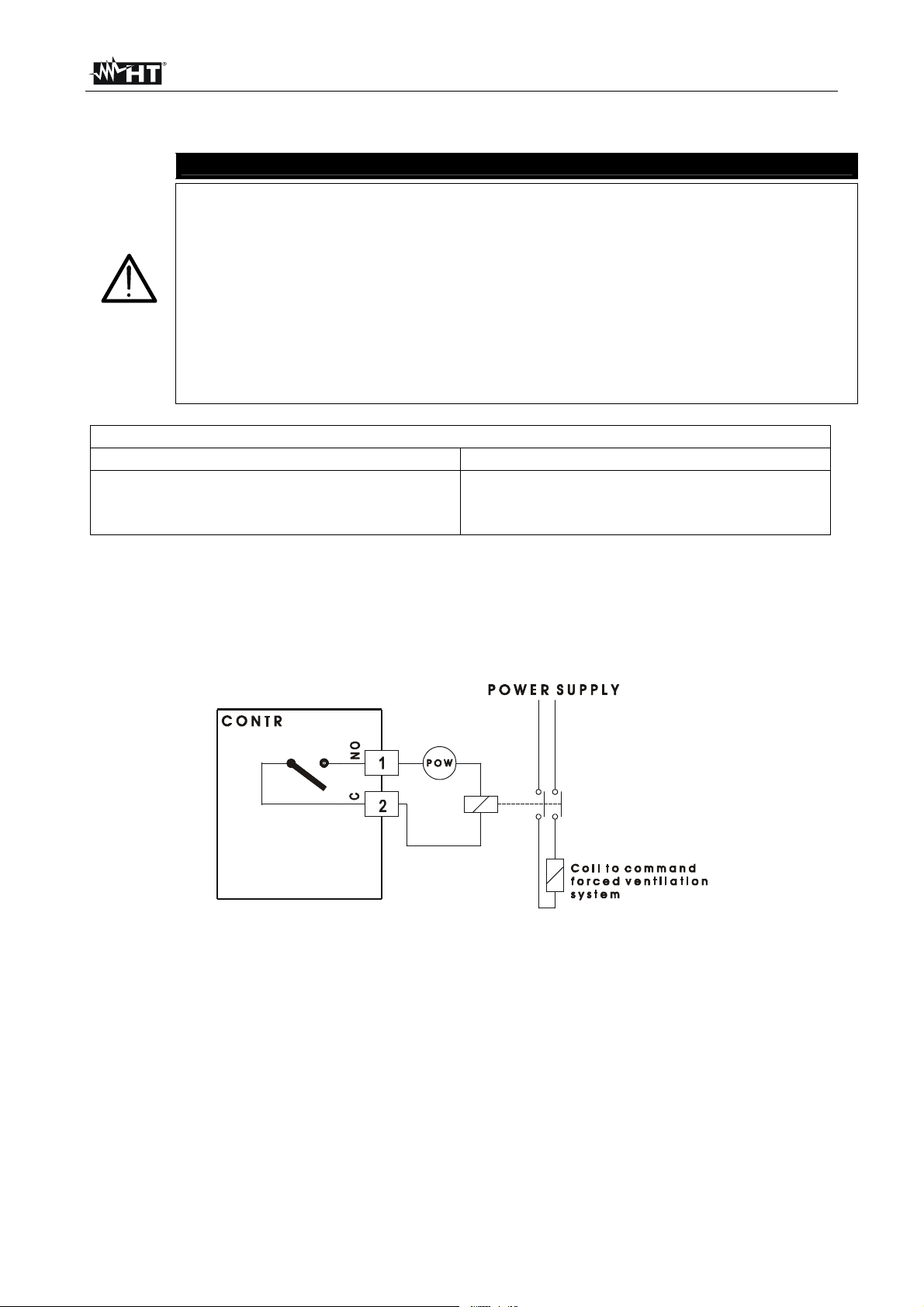
5.2.3. CONTR output circuit
The output circuit CONTR can be used to connect a forced ventilation system or a parallel
device installation. The electrical scheme of connection is presented on following Fig. 6.
Fig. 6: CONTR relay on no alarm condition (normally disabled)
CONTR relay operate a commutation in the following cases:
When HT950N measures a temperature over UA threshold CONTR is activated.
When HT950N measures a temperature under UF threshold CONT R is disabled.
CONTR relay can be more important for operators on solution of various installations
problems.
EN - 10
Page 11

HT950N
5.2.4. T1 output alarm circuit
The output relay connection of T1 pre-alarm circuit is presented on following Fig. 7:
Fig. 7: T1 relay on no alarm conditions (normally activated)
T1 relay operate a commutation in the following cases:
When HT950N measures a temperature over T1 threshold.
Whit Pt100 probes open or shorted.
Power supply switch off on HT950N.
5.2.5. T2 output alarm circuit
The output relay connection of T2 alarm circuit is presented on following Fig. 8:
Fig. 8: T2 relay on no alarm conditions (normally disabled)
T1 relay operates a commutation when HT950N measures a temperature over T2
threshold, after a delay time of 50 seconds.
5.3. MESSAGES ON POWER-ON
This message appear for about 2 seconds on principal display to
r_ N
Ht 950
indicate the realise of internal firmware of meter. N show the
version number.
This message is fixed on PARA and SET display and show the
model of meter. Press ALT.T. or T.MAX key followed by ENT. key
to disappear message.
EN - 11
Page 12

HT950N
5.4. SETUP OF ALARM THRESHOLDS
On HT950N meter it’s possible to set up to four alarm thresholds with values within all
measure range. The sequence of programmable parameters presented cyclically by meter
is the following:
T2 T1 UF UA
Parameters setup is possible using PARA and arrows keys [], [], [] with the
following procedure:
1. Power on HT950N meter.
2. Press PARA key. On PARA display appear “t2” message and on SET display is shown
the last programmed T2 value.
3. Press [] key to move cursor on units, tenths or hundreds values on SET display.
4. Press [] key to increase the parameter value variable from 0 to 9 as for units as for
tenths and from 0 to 1 for hundreds.
5. Press [] key to decrease the parameter value up to 0, minimum value for units,
tenths and hundreds.
6. Press ENT. key to confirm T2 value. HT950N automatically present the following “t1”
parameter.
7. Repeat the previous steps from 1 to 6 for fix the threshold values of T1, UF and UA
parameters.
8. Press ENT. key to exit from last item C_End and return on normal measurement.
WARNING
Range of possible values for T2, T1, UF, UA parameters is from 0°C to
199°C.
The set values of parameters are maintained on memory meter also
when instrument power off.
HT950N don’t execute any measure and don’t show any value at
principal display during temperature threshold setup.
For >200°C temperature measure the meter always show the “200”
value on principal display. For temperature value > 230°C on principal
display is shown the “- - -“ message of disabled probes and T1 relay
open the circuit.
EN - 12
Page 13

HT950N
5.4.1. Example of HT950N meter setup
In the following Fig. 9 is possible to see a simple example diagram with programmable
parameters T1, T1, UA, UF, with relative meaning.
Fig. 9: Example of HT950N meter setup
5.5. CLEAR OF RECORDED MAX TEMPERATURE VALUE
To execute clear of maximum value of temperature recorded by HT950N meter, do the
following procedure:
1. Press T.MAX key to show the maximum temperature value on PARA and SET display.
2. Press [] key before both display lights off. On SET display compare 00 value.
3. From this instance the meter start to recording new maximum values.
EN - 13
Page 14

HT950N
5.6. SETUP OF INPUT PROBES NUMBER
Default internal setup of HT950N meter consists on activation of 3 Pt100 probes only (2U,
2V, 2W). To modify this number operate in following way:
Press PARA key until message C_End compare on SET display.
Press [] key. On SET display the digit “d” starts to blinking.
Press [] or [] key and setting the “111” number onset display. Press ENT. key to
confirm.
On PARA and SET display compare respectively the item “CE nn” where “nn” is a two
digits number with value from 01 to 15. Modify this number with arrows key [] or []
on base of following Table 2 to obtain the desired inputs:
CE C1 (2U) C2 (2V) C3 (2W) C4 (1F)
01 ON
02 ON
03 ON ON
04 ON
05 ON ON
06 ON ON
07 ON ON ON
08 ON
09 ON ON
10 ON ON
11 ON ON ON
12 ON ON
13 ON ON ON
14 ON ON ON
15 ON ON ON ON
Table 2: Setup number of input probes of HT950N
Confirm the operation with ENT. key which guarantee the save of desired inputs and
the exit to normal measurement, at the same time.
6. PREVENTIVE MAINTENANCE
6.1. GENERAL INFORMATION
1. This digital meter is a precision instrument. Whether in use or in storage, please do not
exceed the specification requirements to avoid any possible damage or danger during
use.
2. Do not place this meter in high temperature or expose to direct sunlight.
6.2. CLEANING
For cleaning the instrument use a soft dry cloth. Never use a wet cloth, solvents or water,
etc.
EN - 14
Page 15

HT950N
7. TECHNICAL SPECIFICATIONS
7.1. TECHNICAL CHARACTERISTICS
7.1.1. Inputs characteristics
Inputs: from 1 to 4 PT100 DIN 3-wires
Accuracy: (0.5% rdg + 1dgt)
Range: 0 200°C
Compensation line resistance: automatically
7.1.2. Output characteristics
Outputs: 3 independent relays free of voltage
Current:: 5 A
Nominal voltage: 250 V
Max. commutable voltage: 250 V
Nominal AC1 power : 1250 VA
7.1.3. Safety characteristics
Safety: EN 61010
Overvoltage category: CAT III 300V
Insulation: Class 2, double insulation
Pollution degree: 2
Internal use, max altitude: 2000m
7.1.4. General characteristics
Mechanical characteristics
Case: plastic auto-extinguish (Noryl)
Dimensions: 96(L) x 96(W) x 110(H) mm
Weight: about 800g
Power supply
AC/DC: 24 – 240 V DC/AC
Frequency: DC or 50/60Hz
Consumption: < 10VA
Display
Characteristics: 3 red LED (12x17mm); 2+3 red LED (10x12mm)
7.2. ENVIRONMENTAL CONDITIONS
7.2.1. Climatic conditions
Operating temperature: -10 ÷ 50 °C
Operating humidity: < 70% RH
Storage temperature: -20 ÷ 70 °C
Storage humidity: < 80% RH
7.2.2. EMC
This tester was designed in accordance with EMC standards in force and its compatibility
has been tested in accordance with EN61326-1 (1997) + A1 (1998) + A2 (2001).
7.3. ACCESSORIES
7.3.1. Standard accessories
HT950N meter with the following:
No.8 extractable connectors for Pt100, output relays, power supply.
No 1 EMC filter for power supply cable.
No 2 connectors for fixing on panel with screws.
User’s manual
EN - 15
Page 16

HT950N
8. SERVICE
8.1. WARRANTY CONDITIONS
This equipment is guaranteed against material faults or production defects, in accordance
with the general sales conditions. During the warranty period (one year), faulty parts may
be replaced. The manufacturer reserves the right to decide either to repair or replace the
product.
In case of returning of the instrument, all transport charges must be paid by the customer.
The instrument must be accompanied by a delivery note indicating the faults or reasons of
returning. The returned tester must be packed in its original box. Any damage occurred in
transit because of lack of original packaging will be debited to the customer.
The manufacturer is not responsible for any damage against persons or things.
The warranty won’t be applied to the following cases:
faults due to improper use of the equipment
faults due to combination of the tester with incompatible equipment.
faults due to improper packaging.
faults due to servicing carried out by a person not approved by the company.
faults due to modifications made without explicit authorization of our technical
department.
faults due to adaptation to a particular application not provided for by the definition of
the equipment or by the instruction manual.
The contents of this manual cannot be reproduced in any form without our authorization.
Our products are patented. Our logotypes are registered. We reserve the right to
modify characteristics and prices further to technological developments.
8.2. SERVICE
If the equipment doesn’t work properly, before contacting the SERVICE, test cables and
Pt100 state and change them if necessary.
If the equipment still doesn’t work, make sure that your operating procedure complies with
the one described in this manual.
In case of returning of the instrument, all transport charges must be paid by the customer.
The instrument must be accompanied by a delivery note indicating the faults or reasons of
returning. The returned tester must be packed in its original box. Any damage occurred in
transit because of lack of original packaging will be debited to the customer.
EN - 16
Page 17

Via Righi 126
48018 – Faenza (RA)- Italy
Tel: +39-0546-621002 (4 linee r.a.)
Fax: +39-0546-621144
email:
ht@htitalia.it
http://www.htitalia.com
 Loading...