

Hsun 500ATV User Manual
BRIEF INTRODUCTION TO FOUR-WHEELED
CROSS-COUNTRY VEHICLE MODEL 500ATV
Four-wheeled cross -country vehicle, model 500ATV is a full road condition vehicle which
can be driven on every kinds of road conditions such as sand beach, grassland, forest,village,
construction site country road , This maintenance manual of four-wheeled vehicle model
500ATV (Hereafter called cross -country vehicle for short) compiled by Chongqing Industries
Co., Ltd is specially provided for saler and technical staff of our Group. This manual mainly
introduce the maintenance, removing and repairing method of cross-country vehicle and provide some relative technology and performance data. Because this manual can’t collect the
whole content of cross-country vehicle, it can only help maintainer of our group and it’s saler
have a basic understanding on working principle, maintenance procedure and repairing technology of cross-country vehicle. If you don’t have this knowledge, when repairing cross-coun-
try vehicle, the condition of improper assembling and danger occurs after assembling are easily
happened. Proper operation and maintenance are the advance of your safely driving crosscountry vehicle, it also can reduce the troubles of cross-country vehicle and keep the best
performance of it. The specification, performance and explanation stated in the manual are
determined according to newly design of the vehicle, which are subject to changes without
notce.
In this manual, for specially important requirement, the words of “Warning ” “Caution ” are
labelled to prompt relative maintainer to abide it.
In the manual
Warning
Caution
Show that if the content of “Warning ”isn’t obeyed, the driver, maintainer,
checker will be heavily injuried, even dead.
Show that you must be careful to prevent the vehicle from being damaged.
Maintenance manual of four-wheeled cross-country vehicle model 500ATV
First edition November 2007
This manual is published by publishing factory. maintain the copyright of
publishing. Without permitted, publishing is prohibited.

Content
Content.......................................................................................................................................I
Chapter I General description.......................................................................................................1
Section 1 Description...................................................................................................................1
Section 2 Special tools, instruments & meters...............................................................................2
(I) Special tools.................................................................................................................2
(II) Instruments & meters..................................................................................................3
Section 3 Identification code, label of model and engine No..........................................................4
Section 4 Points for attention in maintenance...............................................................................4
Section 5 Specification.................................................................................................................8
I. How to use conversion table of unit...............................................................................8
(1)How to use conversion table.........................................................................................8
(2)Definition of unit..........................................................................................................8
II. Basic specification........................................................................................................9
III. ATV body...................................................................................................................10
IV. Electric system............................................................................................................11
V. Maintenance specification of engine.............................................................................13
Section 6 Wiring diagram of ATV.................................................................................................16
(I) Technical explanation and requirement, details of relative component.............................16
(II) Technical requirement..................................................................................................23
(III) Details of relative component.....................................................................................23
Section 7 Requirements for torque of fastener...............................................................................24
(1)ATV body....................................................................................................................24
(2) Engine.........................................................................................................................27
(3) General torque specification.........................................................................................29
Section 8 Lubrication...................................................................................................................30
(1)Lubrication oil way.......................................................................................................30
(2) Lubrication diagram.....................................................................................................31
Section 9 Lubrication point and type of lubricants........................................................................33
(1) Lubrication point and type of lubricants(ATV body).....................................................33
(2) Lubrication point and type of lubricants(Engine)..........................................................34
Chapter II Maintenance and adjustment of vehicle.......................................................................35
Section 1 Periodic maintenance/ lubrication..................................................................................35
Section 2 Disassembly and assembly of cushion, fender and fuel tank...........................................36
(I) Cushion.......................................................................................................................36
(II) Rear fender..................................................................................................................37
(III) Fuel tank....................................................................................................................39
(IV) Front fender...............................................................................................................41
I

Section 3 Maintenance and adjustment of vehicle body................................................................43
(I) Wear inspection of front and rear brake.........................................................................43
(II) Adjustment of front brake............................................................................................44
(III)Adjustment of free clearance of left lever and rear brake pedal......................................44
(IV) Position adjustmen of steering lever............................................................................46
(V) Check the final gear oil level.........................................................................................47
(VI) Changing the final gear oil lvevel................................................................................47
(VII) Checking the differential gear oil................................................................................47
(VIII) Checking the constant velocity joint dust boot.........................................................48
(IX) Checking the steering system.....................................................................................49
(X)Adjustment of toe-in of front wheel.............................................................................50
(XI) Adjustment of front/rear shock absorber.....................................................................51
(XII) Inspection of tire.......................................................................................................52
(XIII) Inspection of rim......................................................................................................53
Section 4 Maintenance and adjustment of electrical appliance.......................................................54
(I) Inspection of battery....................................................................................................54
(II) Inspection of fuse.......................................................................................................55
(III) Replacement of headlight lamp....................................................................................56
Section 5 Maintenance and adjustment of engine.........................................................................58
(I) Clean of air filter...........................................................................................................58
(II) Inspection of spark plug..............................................................................................60
(III) Adjustment of idle speed............................................................................................61
(IV) Adjustment of free clearance of throttle grip................................................................61
(V) Adjustment of speed limitator......................................................................................62
(VI) Adjustment of valve clearance....................................................................................63
(VII) Adjustment of timing chain tension............................................................................65
(VIII) Inspection of ignition timing.....................................................................................66
(IX) Measuring of compressive force.................................................................................67
(X) Inspection oil quantity of engine.................................................................................68
(XI) Replacement of engine oil and inspection of oil flow...................................................69
Chapter III Repair and maintenance of vehicle body......................................................................72
Section 1 Drive train....................................................................................................................72
(I) Troubleshooting...........................................................................................................72
(II)Front constant relocity joints and differential gear.........................................................75
(III) The rear constant velocity joint,final gear assembly and drive shaft.............................82
Section 2 Front wheel/rear wheel/brkae........................................................................................ 91
(I)Front wheels and brake discs........................................................................................91
(II) Rear wheels and brake disc.........................................................................................94
(III) Front and rear brake..................................................................................................96

Section 3 Steering system...........................................................................................................98
(I) Removal steps of handlebar.........................................................................................98
(II) Removal steps of steering stem...................................................................................99
(III) Inspection content....................................................................................................100
(IV) Installment steps.......................................................................................................102
Section 4 Arms/shock absorber/stabilizer....................................................................................103
(I) Front arms and front shock absorber............................................................................103
(II)Rear arms/rear shock absorber/stabilizer.......................................................................106
Chapter IV Engine........................................................................................................................109
Section 1 Disassembly of engine..................................................................................................109
(I) Disassembly of engine.................................................................................................109
Section 2 Inspection and maintenance of engine...........................................................................121
(I) Cylinder head cover assy..............................................................................................121
(II) Cylinder head assy......................................................................................................122
(III) Disassembly of the V-belt assy...................................................................................136
(IV) Transmission.............................................................................................................144
(V) Recoil starter...............................................................................................................154
(VI) Crankcase..................................................................................................................158
Section 3 Carburetor....................................................................................................................160
(I) Disassembly of carburetor...........................................................................................160
(II) Assembly of carburetor...............................................................................................164
(III) Specifications.............................................................................................................164
Section 4 Cooling system............................................................................................................165
Chapter V Electric appliance........................................................................................................170
Section 1 Inspect switch.............................................................................................................171
Section 2 The bulbs and bulb sockets.........................................................................................174
Section 3 Ignition system............................................................................................................177
Section 4 Electric starting system................................................................................................182
Section 5 Charging system..........................................................................................................187
Section 6 Lighting system...........................................................................................................189
Section 7 Signal system..............................................................................................................194
Section 8 Cooling system............................................................................................................204
Section 9 2WD/4WD selecting system........................................................................................209
Chapter VI Troubleshooting........................................................................................................214
(I) Starting failure/hard starting.........................................................................................214
(II) Poor idle speed performance........................................................................................215
(III) Poor medium and high-speed performance..................................................................215
(IV) Faulty drive train........................................................................................................216
(V) Faulty gear shifting.....................................................................................................217
(VI) Faulty clutch performance..........................................................................................217
III

(VII) Faulty brake..............................................................................................................218
(VIII) Shock absorber malfuncation...................................................................................219
(IX) Unstable handling......................................................................................................219
(X) Lighting system..........................................................................................................219
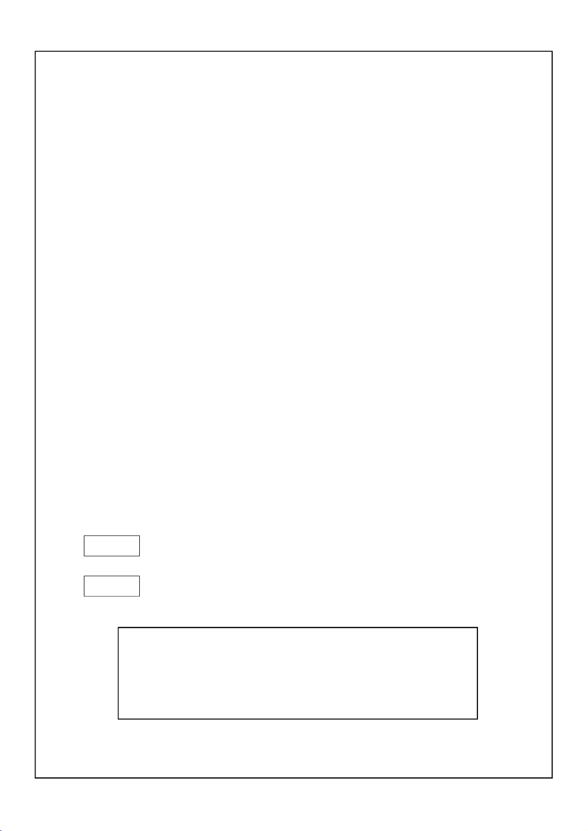
Chapter I General description
Section 1Description
123
9
1112
10
16
15
45
17
13
1819
6
7
14
8
1.Front wheel
2.Headlight
3.Steering lever
4.Shift lever
5.Fuel lock
6.Hand-operated lever
7.Tail light
8.Rear wheel
9.Rear luggage carrier
10.Exhaust silencer
11.Cushion
12.Fuel tank cover
13.Rear brake pedal
14.Front luggage carrier
15.Left lever of rear brake
16.Fixing clamp of rear brake
17.Main switch lock
18.Throttle grip
19.Right lever of front brake
20. Left switch unit
20
Caution:
The ATV you purchased maybe slightly differ from the pictures in the manual due to
improvement or other changement.
-1-

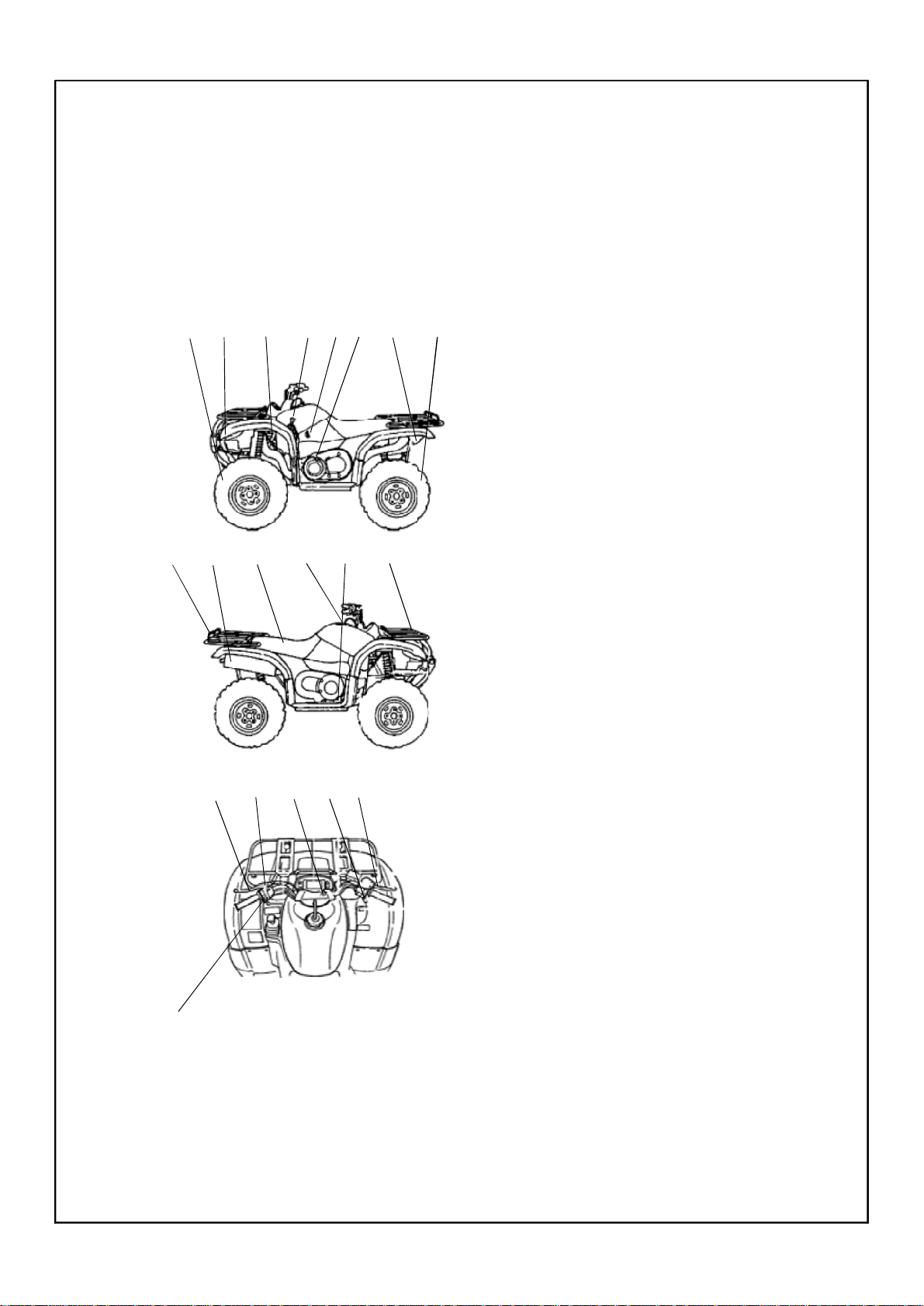
Section 2 Special tools, instruments and meters
(I) Special tools
Special tools is the necessary tools used for accurately adjustment and assembly, it is
helpful to prevent the maintenance defects and components damage caused by using improper
tools.
1.Wrench for valve adjustment mainly used for adjusting valve clearance. Specification:
3mm 90890-01311
2.Puller for piston pin, mainly used of removing pistion pin.
3.Remover for rotator, mainly used for pulling magneto rotator form crank.
4. Clamp for rotator, mainly used for clamping magneto rotator when removing it to pre-
vent it’s rotation due to torque force.
5.Stop rotating meter for rotator, mainly used for removing and assembling rotator of kick
starter.
6.Puller for crank, mainly used for disassembling crank from crankcase.
7.Puller for rocker shaft, mainly used for removing rocker shaft.
8.Compressing tools for spring of valve, mainly used for fixing and compressing spring
when assembling valve lock clamp.
9. Assembling and disassembling tool for valve guide, mainly used for assembling and
disassembling valve guide.
10.Assembling buffer, mainly used for assembling crank and balancing gear.
11.Hollow sleeve, mainly used for assembling crank and balancing gear.
12.Assembling toal for crank, mainly used for assembling crank and balancing gear.
13.Assembling and disassembling joint for universal coupling, mainly used for assembling
and dismsembling universal coupling.
14.Assembling and disassembling disc, mainly used for assembling and disassembling re-
verse gear.
15.Fixed puller for gear, mainly used for assembling and disassembling gear.
For the above tools, you can select with reference to special tools of the same type
of vehicle.
-2-
(II) Instruments and meters
The following instruments and meters can be selected with reference to the same type of
vehicle.
speedometer of engine
(90890-03113)
Ignition timing meter
(90890-03141)
multimeter
spark tester of spark plug
barometerignition checker
measuring tool of gasoling
(90890-01312)
dial indicator
-3-
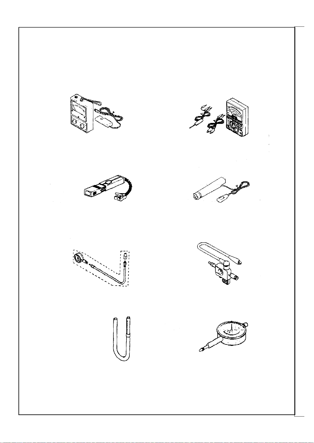
Section 3 Identification code, label of model and engine N0.
Identification code
It is engraved on the left or right side of
①
rear supporting main tube of frame comp.
②
Section 4 Points for attention in maintenance
1.Preparation when disassembling
1.1 First clean the dirt, mud and attachment
on the vehicle befor removing or disassembling.
1.2 Use proper special too cleaning device
and means.
1.3 Keep all the components away from fire
source. Pay attention to the safety, Don’t be
burned by the high temperation portion of engine,
exhuaster and silencer etc. Be sure to take care
of each other when operation with other people.
1.4 When disassembling the ATV, put the
mated components, such as gear pairs, cylinder,
piston and other “mated” components by normal running in together, When assembling or
replacing these components, they should be in
pairs.
1.5 When disassembling the engine, clean
all the components and put in the tray in the or
Engine N0.
It is engravd on the rear part of left crankcases
of engine.
der of disassembly, this in assembling, can
not only increase the assembling speed, but also
ensure the rightness of assembling.
2.Replace the components
When replacing the components, be sure to
use qualified products provided by use lubricants
and grease which brank is assigned by lubricate.
3.Oil seal, shim, o-ring clip split pin,
elastic washer.
3.1 When disassembling to maintain the
engine, in order to ensure that the reassembled
engine have good sealing and connecting part is
fixed and reliable, all the oil seal, shim, o-ring,
clip, split pin and elastic washer should be
replaced, be sure to keep lip of oil seal surface
of shim and o-ring in cleaning condition.
3.2 When reassembling, apply lubricants to
lubricate all the mated components and bearing,
apply grease for oil seal.
-4-
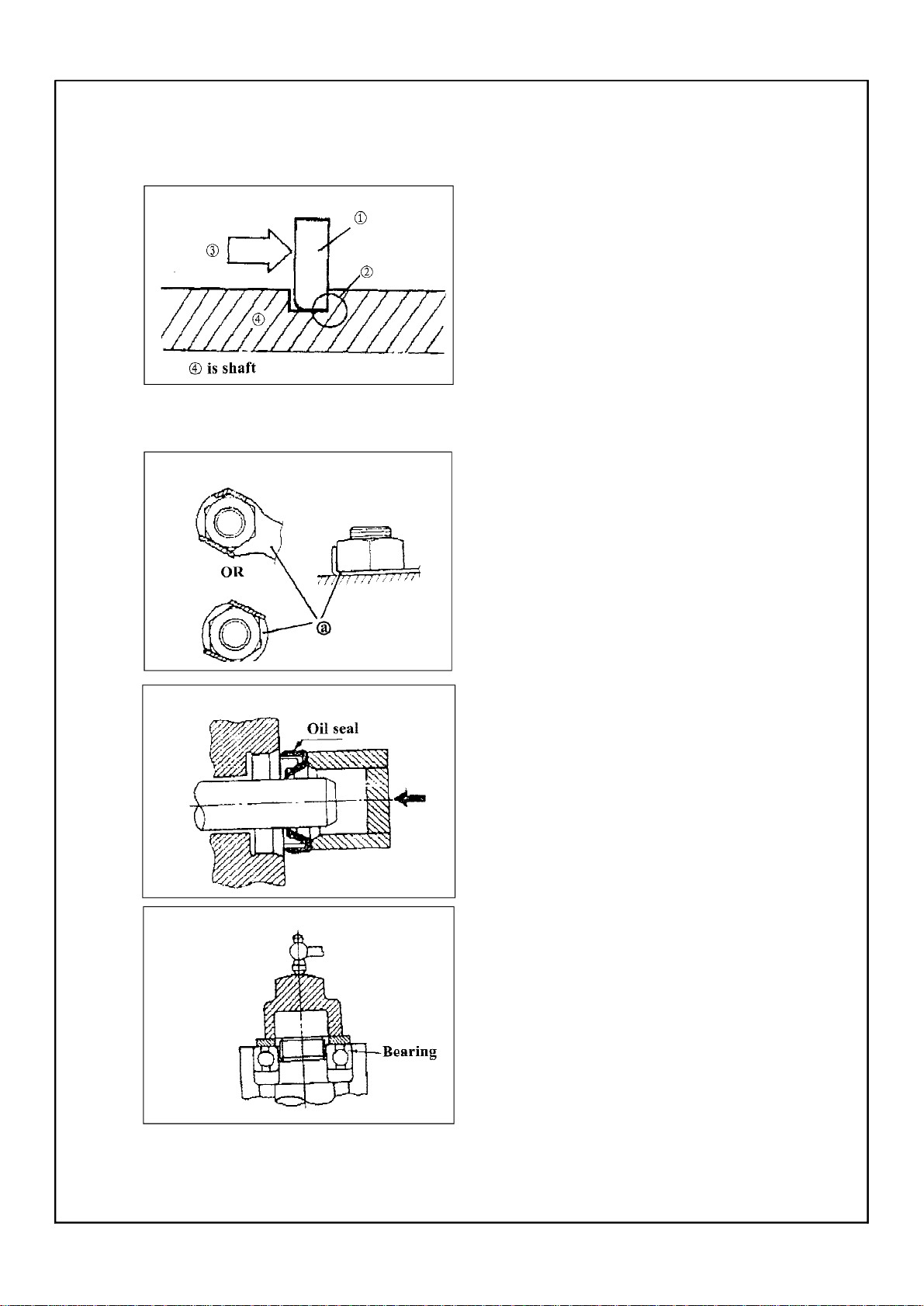
4. Clip
4.1Before assembling, be sure to check all
the clips carefully.Use a new one after removing the clip of piston pin. When mounting clip
ring ① make the sharp face ② the opposite position of impacted face ③ of clip.(see left fig)
5.Locking washer /shim and location pin
5.1When reassembling after disassembling.
be sure to replace all the locking washer /shim
and location pin @ After bolt or nut is fixed on
the locking position. be sure to bend and fix both
ends of locking shim along head of bolt or direction of nut.
6.Bearing and oil seal
6.1 When assembling bearing and oil seal
put the mark or specification of manufacturer
outside, When assembling oil seal apply a thin
film of lithium-base grease on the lip of oil seal.
Caution:
Don’t blow to dry the inside of bearing with
compressed air, this would damage the surface
of bearing.
-5-
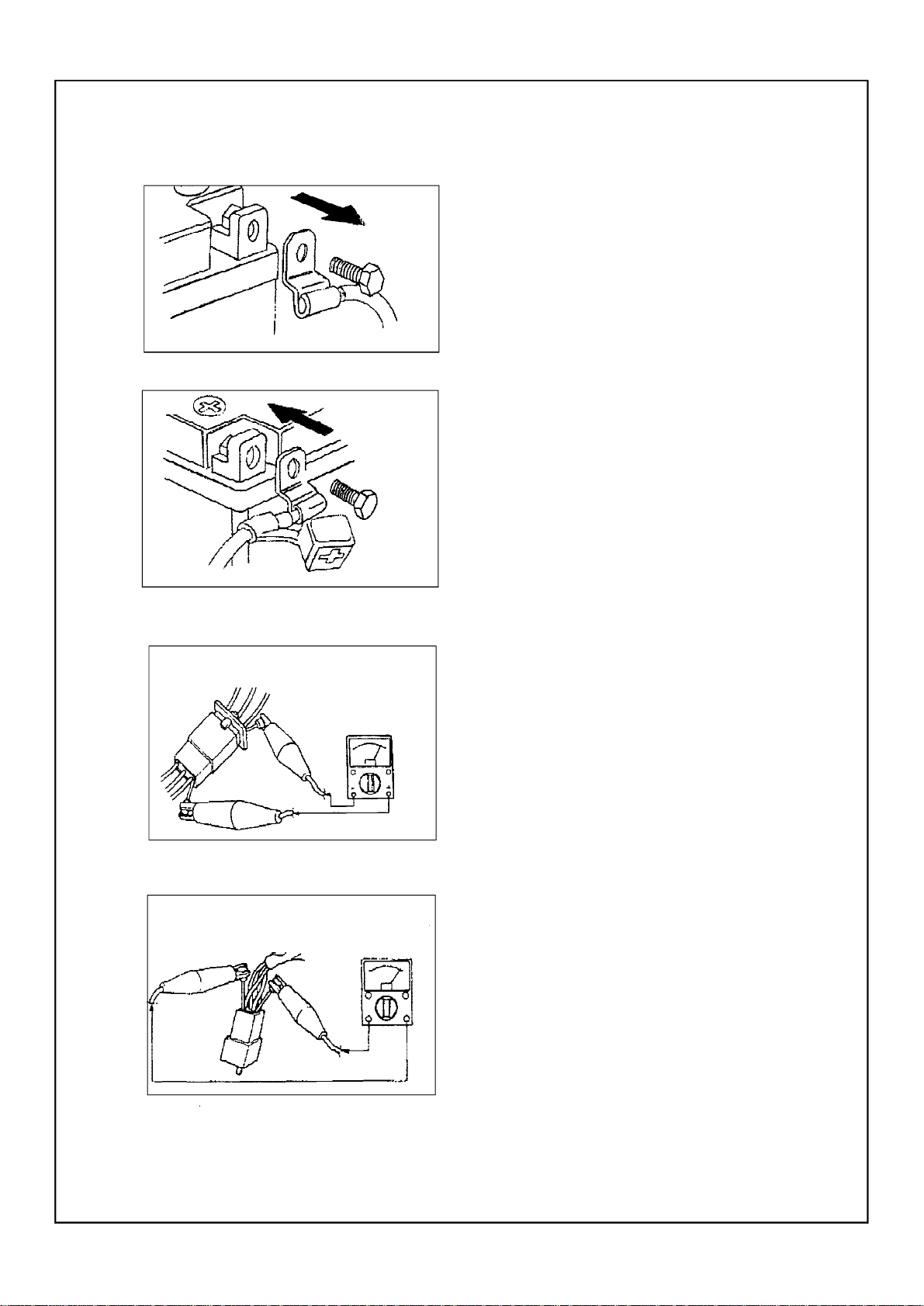
Fig.7.1Removal of negative pole wire of battery
Fig.7.2 Connection of positive pole wire of battery
7.Check of electirc parts
7.1 Check the rust, dirt and moisture etc.
of connector, if there is moisture, please blow it
dry and clear the rust and dirt.
7.2 The eclectolyte inside the battery is a
kind of corrosive, when operation exercise shall
be taken not to let the electrolyte splash on the
body.
7.3 When repairing wire on electric parts,
first remove the wire on the termianl of negative pole of battery(see fig.7.1).When tightening or loosening bolt of terminal of big capacity
battery, don’t let the wrench contact with engine or other metal parts of vehicle body to
avoid the electric shock.
7.4 When connecting the wire of battery,
first connect the opositive pole wire of battery,
then connect the negative pole wire After connecting the wire, apply clean grease on the terminal to avoid the increasing of resistance due
to rust.
-6-
7.5 Check the terminal of connector
a Grip two terminals of connector together,
check with the multimeter.(see fig.7.3,fig.7.4)
Fig.7.3
Fig.7.4
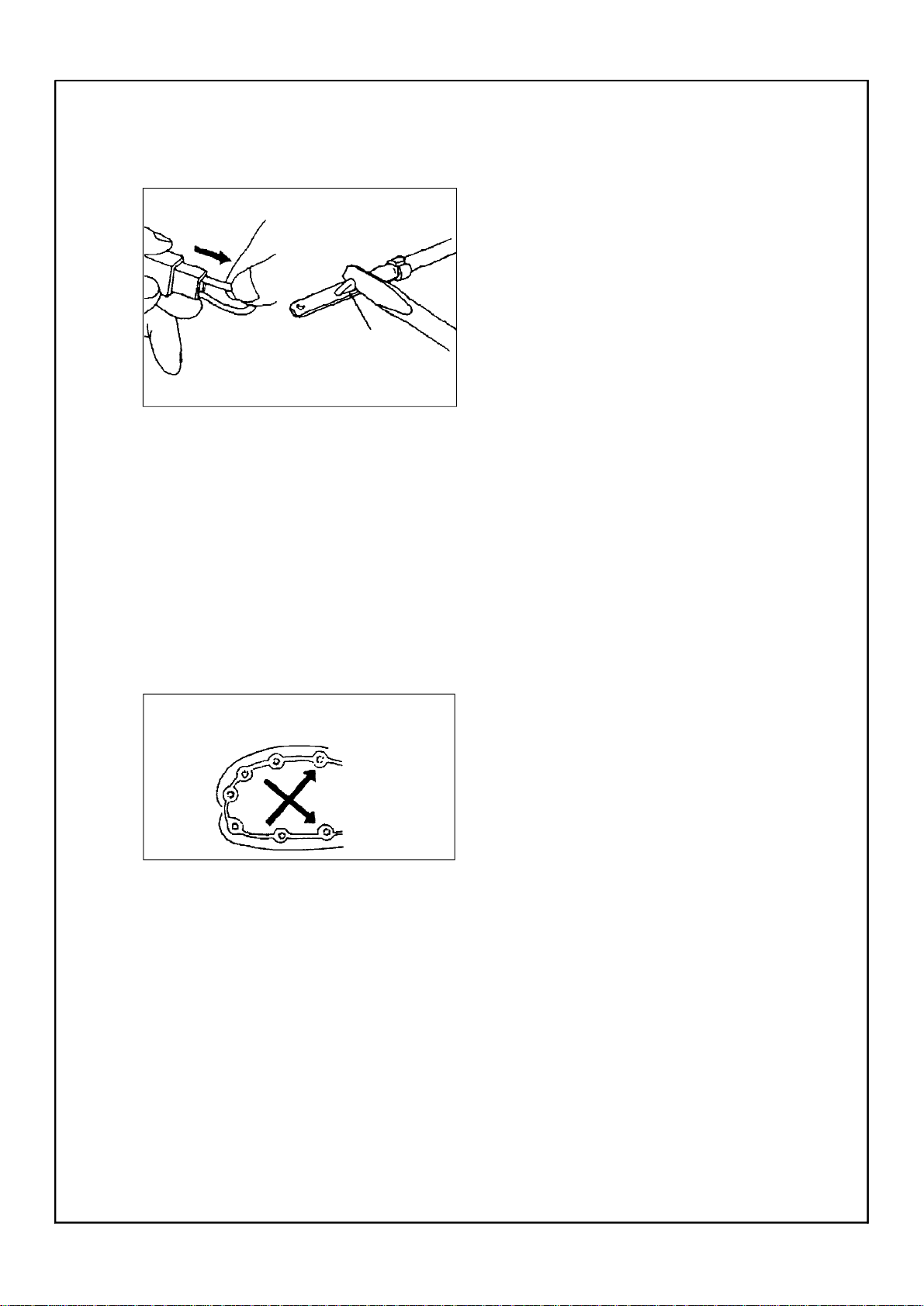
Plug pin
Fig.7.5
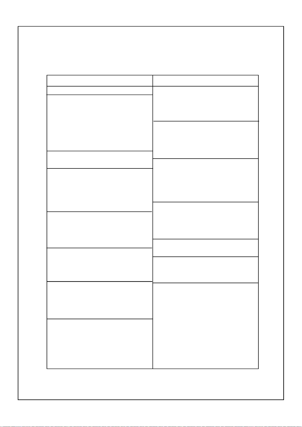
According to
intersecting
Fig.8.1Tightening method of screw and nut.
b. If joint is slack, bend the plug pin
upward, then connect with connector plug(see
fig7.5)
7.6 Before mounting new fuse, check if the
load of fuse of components is right, especially
for the portion being burned broken regularly,
then mount the fuse having proper current value.
7.7Wire connector have two kinds, one is
single-head connector, another is multi -head
one.
Before connecting single-head connector ,
check if there is broken on the housing of joints,
the joint is fixed and if there is a broken phenomenon on it. When inserting the joint, it should
be fixed, then put in plastic coating after
inserting.
In general, multi-head connector is plastic
one, and locking catch is designed. When disassembling the connector, first open locking catch
when connecting again, first check if all the joint
is in good condition, if there is bent or twisted
on them. After connecting, align the locking
catch and lock them.
8. Use torque spanner to tighten screw and
nut, and as per specified torque to tighten them.
It should be tightened in steps from big ones to
small ones, from inside to outside and along the
direction of diagonal line to intersect. A s shown
in fig.8.1.
-7-

Section 5 Specification
(I) How to use conversion table of unit
(1)How to use conversion table
All the specified documents in this manual are taken SI and Metric as unit. With the follow-
ing conversion table, metric unit could be conversed into imperial unit.
METRIC MULTIPLY IMPERIAL
mm 0.03937in
2mm ± 0.03937=0.08in
Conversion table
Conversion between metric and imperial
Torque
Weight
Length
Volume/capacity
Others
Known unit
m.kg
m.kg
cm.kg
cm.kg
kg
g
km/hr
km
m
m
cm
mm
cc(cm3)
cc(cm3)
lit(liter)
lit(liter)
kg/mm
2
kg/cm
Centigrade
Multiply
7.233
86.794
0.0723
0.8679
2.205
0.03527
0.6214
0.6214
3.281
1.094
0.3937
0.3937
0.03527
0.06102
0.8799
0.2199
55.997
14.2234
9/5(℃)+32
product
ft.lb
in.lb
ft.lb
in.lb
lb
oz
mph
mi
ft
yd
in
in
oz(IMP liq)
cu.in
qt(IMP liq)
gal(IMP liq)
1b/in
psi(1b/in2)
Fahrenheit(0F)
(2)Definition of unit
Unit
mm
cm
kg
N
Nm
m.kg
Pa
N/mm
L
3
cm
r/min
-8-
Read
Millimetre
Centimetre
Kilogram
Newton
Newton meter
Meter kilogram
Pascal
Newton per millimeter
Liter
Cubic centimeter
Revolutions per minute
Definition
10-3Meter
10-3Meter
103Gram
1 lilo ×meter /second
Newton ×meter
Meter ×kilo
Newton/meter
Newton/centimeter
2
Measurement
Length
Length
Weight
Force
Torque
Torque
Pressure
Rigid of spring
Volume or capacity
Rotational speed
II.Basic specification
Item
Specification
Dimension:
Overall length 2085mm
Overall width 1200mm
Overall height 1274mm
Height of cushion 877mm
Axle base 1285mm
Min.ground clearance 280mm
Min.turning radius 3000mm
Basic weight:
Engine oil(with full tank) 348KG
Engine type Liquid-cooled 4-stroke,SOHC
Cylinder arrangement Forward-inclined single cylinder
Displacement 493cc
Bore × stroke 87.5 × 82mm
Compression ratio 10.2:1
Starting system Electric starter and recoil starter
Lubrication system pressure splash
Engine oil SAE20W/40,SAE15W/40
classfication of recommendedengine oil Model SE,SF,SG or above model
Periodic oil replacement 1.9L
Replace filter 2.0L
Overall capacity 2.2L
Oil capacity of gearbox 0.25L
Model: SAE80 API“GL-4” Hypoid gear oil
Capacity of main fuel tank 18L.Non-lead gasolining
No.90#
Capacity of reserved fuel tank 4L
Item
Shifting type:
Low speed 2.466
High speed 1.473
Reverse gear 1.471
Frame:
Bracket steel tube
Caster angle 3°
Trail 21mm
Tire:
Type Tubeless
Specification of front wheel AT25 × 8-12
Specification of rear wheel AT25 × 10-12
Pressure of front wheel 32~38kPa
Pressure of rear wheel 27~33kPa
Brake:
Type of front brake Dual disc brake
Operation type Right-hand operation to brake
Type of rear brake Single disc brake
Operation type Left hand or Right-foot to brake
Front suspension Double wishbone
Rear suspension Double wishbone
Specification of shock absorber
Front shock absorber spring
Rear shock absorber spring
Specification
Carburetor:
Type MIKUNI DSR36-89
Type of spark plug NGK:DPR7EA-9
Clearance of spark plug 0.8-0.9mm
Type of clutch Wet automatic centrifugal type
Output
Primary reduction system V-belt
Secondary reduction system Shaft drive
Reduction ratio 7.944
Transmission type V- belt automatic
Output type Non-cycle,four gear forward,gear back
Operation Left-hand operation
Electric system:
Ignition system C.D.I
Magneto system A.C magneto
Battery/capacity GT × 20L-BS
12V,20AH
Headlight 12V,35W/35W × 2
Taillight 12V,10W × 2
Neutral indicator 12V,3W × 1
Reverse indicator 12V,3W × 1
High-beam indicator 12V,3W × 1
-9-
III.ATV body
Steering system
Type of steering bearing
Type
Material of rim
Front
wheel
Front
brake
Rear
wheel
Size of tire
Size of rim
Radial runout of rim
Lateral swing of rim
Type
Disc outside diameter × thickness
Pad thickness
Brake fluid type
Type
Material of rim
Size of tire
Size of rim
Radial runout of rim
Item
StandardLimit
Ball and race bearing
Panel wheel
Aluminum
AT 25× 8-12
AT 12× 6.0
Dual
220.0×3.5mm
4.2mm
DOT 4
Panel wheel
Aluminum
AT 25×10-12
AT6.0 ×7.5
2.0mm
2.0mm
1.0mm
2.0mm
Lateral swing of rim
Type
Rear
brake
Brake
lever and
brake
pedal
Free play of throttle grip
-10-
Disc outside diameter × thickness
Pad thickness
Brake fluid type
Free play of brake lever (left)
Free play of brake lever (right)
Free play of rear brake pedal
2.0mm
Single
150.0×8.5mm
7.0mm
DOT 4
5-7mm
5-7mm
20-30mm
3-5mm
Item
StandardLimit
Elastic coefficient of spring K1
Front
suspen-
sion
system
Free length of suspending spring
Stoke of shock absorber
Pre-tension force of spring is
adjsutable or not
Elastic coefficient K2
Rear
suspen-
sion
Free length of suspending spring
Assembling length
system
Stroke of shock absorber
Pre-tension force of spring is
adjustabe of not
Rear
Assembling free play(left-end)
wheel
fork
Assembling free play (right-end)
IV.Electric system
20N/mm/0-86mm
295mm
86mm
Can’t adjustable
36.4N/mm/0-95mm
277mm
235.5mm
95mm
Can’t adjustable
1.0mm
1.0mm
Spark
plug
Ignition
coil
Ignition
system
Item
Voltage of electric system
Type
Resistance
Clearance of spark plug
Resistance of primary coil
Resistance of secondary coil
Clearance of min. spark
Ignition timing (Before upper stop point)
Advancing angle of ignition (Before upper stop point)
Type of ignition advance
StandardLimit
12V
DPR7EA-9/NGK
10k Ω
0.8-0.9mm
At 20℃(680F),0.18-0.28Ω
At 20℃(680F),6.32-9.48KΩ
6mm(0.24in)
10o/1,500r/min
5400±200r/min
Digital type
-11-
Item
StandardLimit
Magneto
Rectifier
Charging
system
Battery
Broken
circuit of
circuit
system
Relay of
cut-off
current
Resistance of induction coil/colour
Resistance of source coil /colour
Type of C.D.I
No-loading adjusting volatage
Voltage-resisting value
Type
Rated ouput voltage
Coil resistance/colour
Specific gravity
Type/capacity
Type
Main fuse
Reserved fuse
Coil resistance
Diode
At 20℃(680F),189-231Ω Blue black
At 20℃(680F),459-561Ω Yellow/green-red
Electric capacity contactless type
14.1-14.9V
200V
A.C magneto
At 5000r/min 13.5-15V
At 20℃(680F),1.0-1.2Ω White -white
1.28
GTX20L-BS/12V, 20AH
Fuse
20A
10A
At 20℃(680F),72-88Ω
Yes
Electric
starting
system
Electric
starting
system
-12-
Type
Starting
motor
Starting
relay
Output power
Resistance of armature coils
Ampere
Coils resistance
Constant mesh type
0.3KW
At 20℃(680F),0.025-0.035Ω
180A
At 20℃(680F),3-5Ω

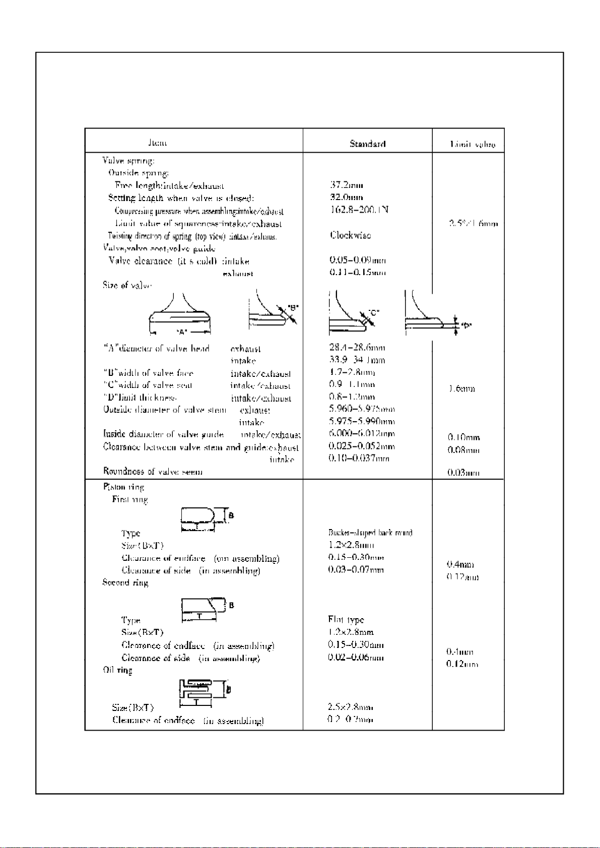
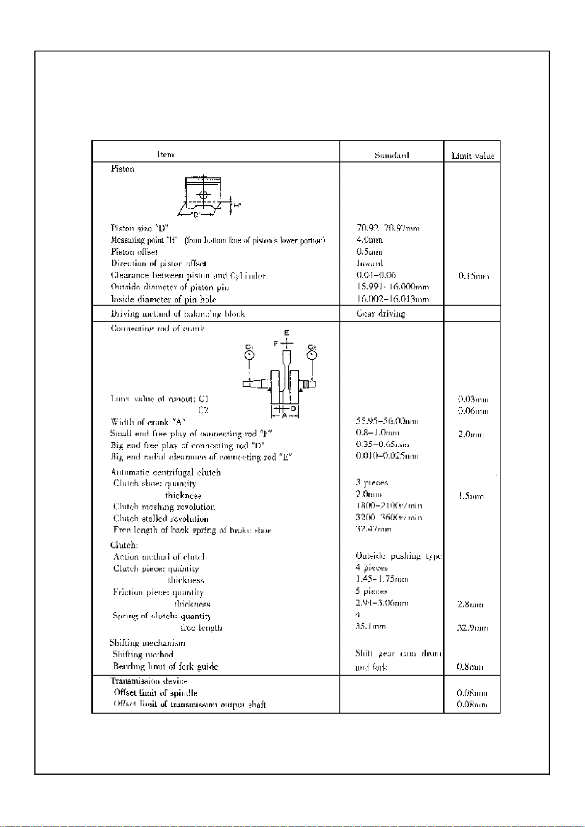
V.Maintenance specificationof engine
-13-
-14-
-15-
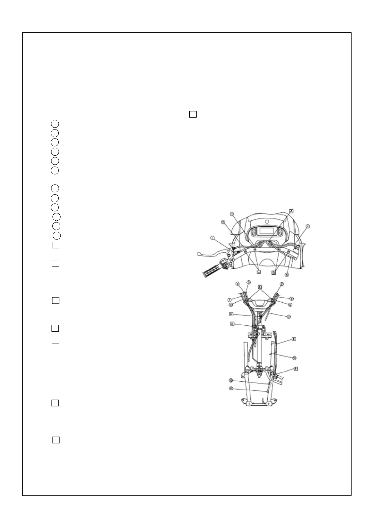
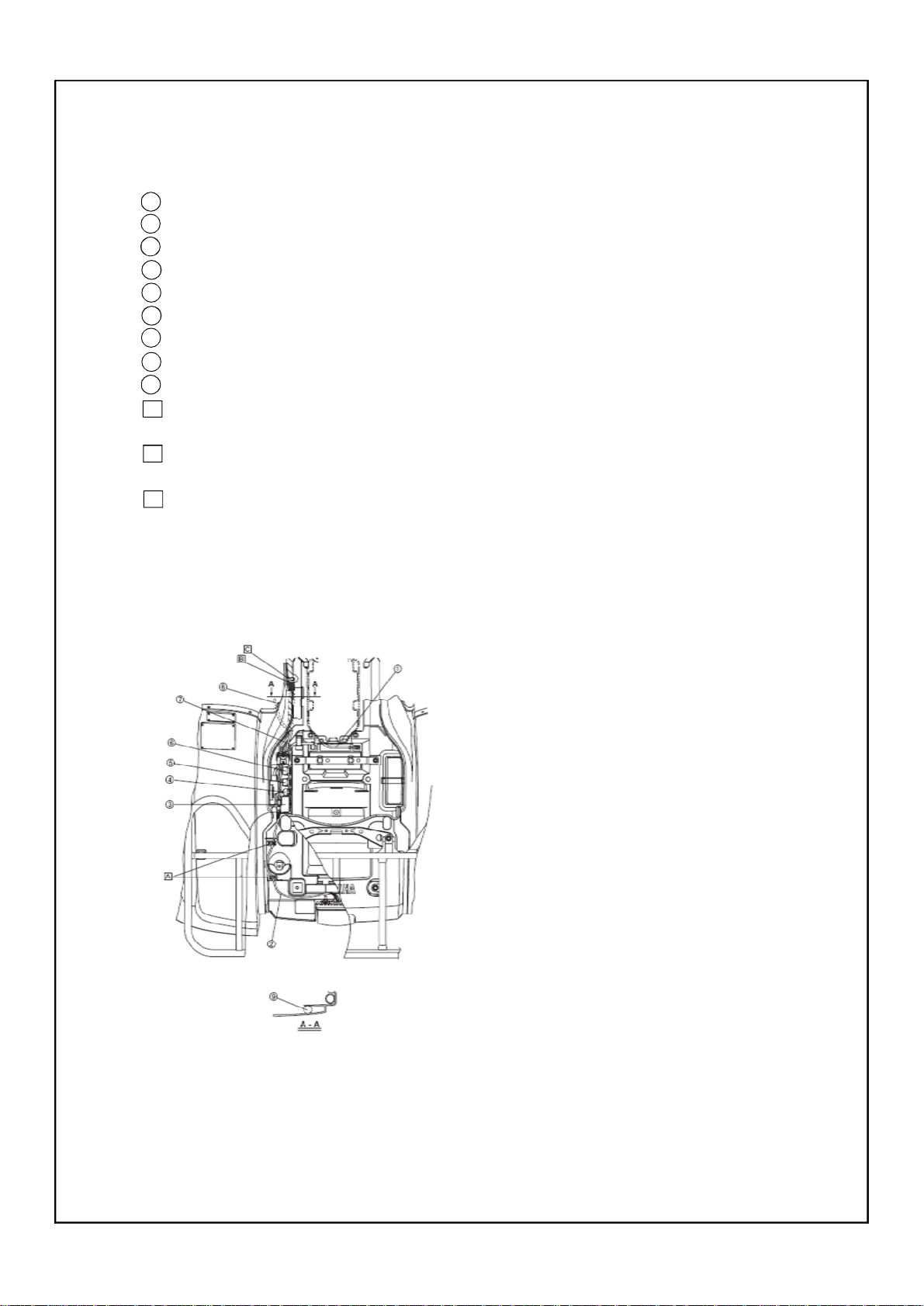
Section 6 Wiring diagram of ATV
(I)Technical explanation and requirement, details of relative compenent.
1.Technical explanation
1 Rear brake light switch
2 Rear brake cable
3 Starter cable
4 Front brake hose
5 Throttle cable
6 On-command four-wheel drive switch and
differential
7 Front brake light switch lead
8 Handlebar switch lead
9 Rear brake light switch lead
10 Fan motor lead
11 Sub-wire harness (to gear motor)
12 Differential gear case breather hose
A Pass the cable, hose, and leads between
the meter assembly and plastic cover.
B Fasten the front brake light switch lead,
and the on-command four-wheel drive switch
and differential gear lock switch lead behind
the handlebar with a plastic band.
C Fasten the handlebar switch lead and rear
brake switch lead behind the handlebar with
a plastic band.
D Pass the cable, hose, and leads through
the slit of the handlebar cover.
E Fasten the thermo switch 2 lead, fan motor lead, coolant reservoir breather hose,
coolant reservoir hose, gear motor lead and
differential gear case breather hose with a
plastic band. Install the plastic band facing
inward.
F Fasten the gear motor lead and differential gear case breather hose with a plastic
band. Be sure not to pinch the hose. Install
the plastic band facing inward.
G Pass the brake hose through the hose
guide.
H Fasten the on-command four-wheel drive
switch and differential gear lock switch lead,
front brake light switch lead, handlebar
switch lead, and rear brake light switch lead
on the front side on the steering stem with a
plastic locking tie.
-16-
1 Park brake light switch
2 On-command four-wheel drive switch and
differential gear lock switch lead
3 Headlight lead
4 Coolant reservoir breather hose
5 Differential gear case breather hose
6 Fan motor breather hose
7 Main switch lead
8 Auxiliary DC jack lead
A To the front brake light switch, on-command fourwheel drive switch and differential gear lock switch, handlebar switch, and
rear brake light switch.
B After routing all leads and couplers fasten them together with a plastic band.
C Pass the on-command four-wheel drive
switch and differential gear lock switch lead
and headlight lead through the guide on the
front fender.
D Pass the coolant reservoir breather hose
and differential gear case breather hose
through the guide on the front fender.
E Pass the fan motor breather hose through
the guide on the front fender.
F Pass the headlight lead through the guide
on the front fender.
-17-
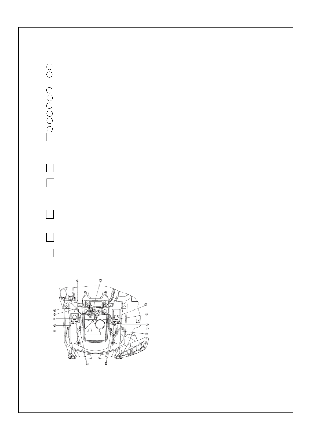
1 Coolant reservoir hose
2 Fan motor lead
3 Ignition coil coupler
4 Starter cable
5 Fuel tank breather hose
6 Coolant reservoir breather hose
7 Gear motor lead
8 Differential gear case breather hose
9 Thermo switch 2 lead
A Connect the ignition coil coupler under
the front fender.
B Pass the starter cable through the cable
guide at the front of plastic cover.
C Route the fuel tank breather hose behind the plastic cover.
D Insert the fuel tank breather hose into
the hole into the handlebar cover.
E Make sure that the starter cable does not
have any slack between the cable holder plastic cover and the plastic clamp.
F Slacken the coolant reservoir hose, and
then insert it between the frame and the
water pump inlet. Be sure not to pinch the
hose.
G Fasten the coolant reservoir hose and
water pump inlet hose with a plastic band.
Be sure to not pinch the hoses. Install the
plastic band facing inward.
H Fasten the coolant reservoir breather
hose, coolant reservoir hose, and water pump
inlet hose with a plastic band. Be sure not to
pinch the hoses. Install the plastic band facing inward.
I Fasten the gear motor lead and differential gear case breather hose with a plastic
band. Be sure not to pinch the hose. Install
the plastic band facing inward.
J Clamp the water pump inlet hose and
thermo switch 2 lead with a plastic clamp.
K Fasten the thermo switch 2 lead, fan
motor lead, coolant reservoir breather hose,
coolant reservoir hose, gear motor lead,
and differential gear case breather hose
with a plastic band. Install the plastic band
facing inward.
L To the differential gear
-18-

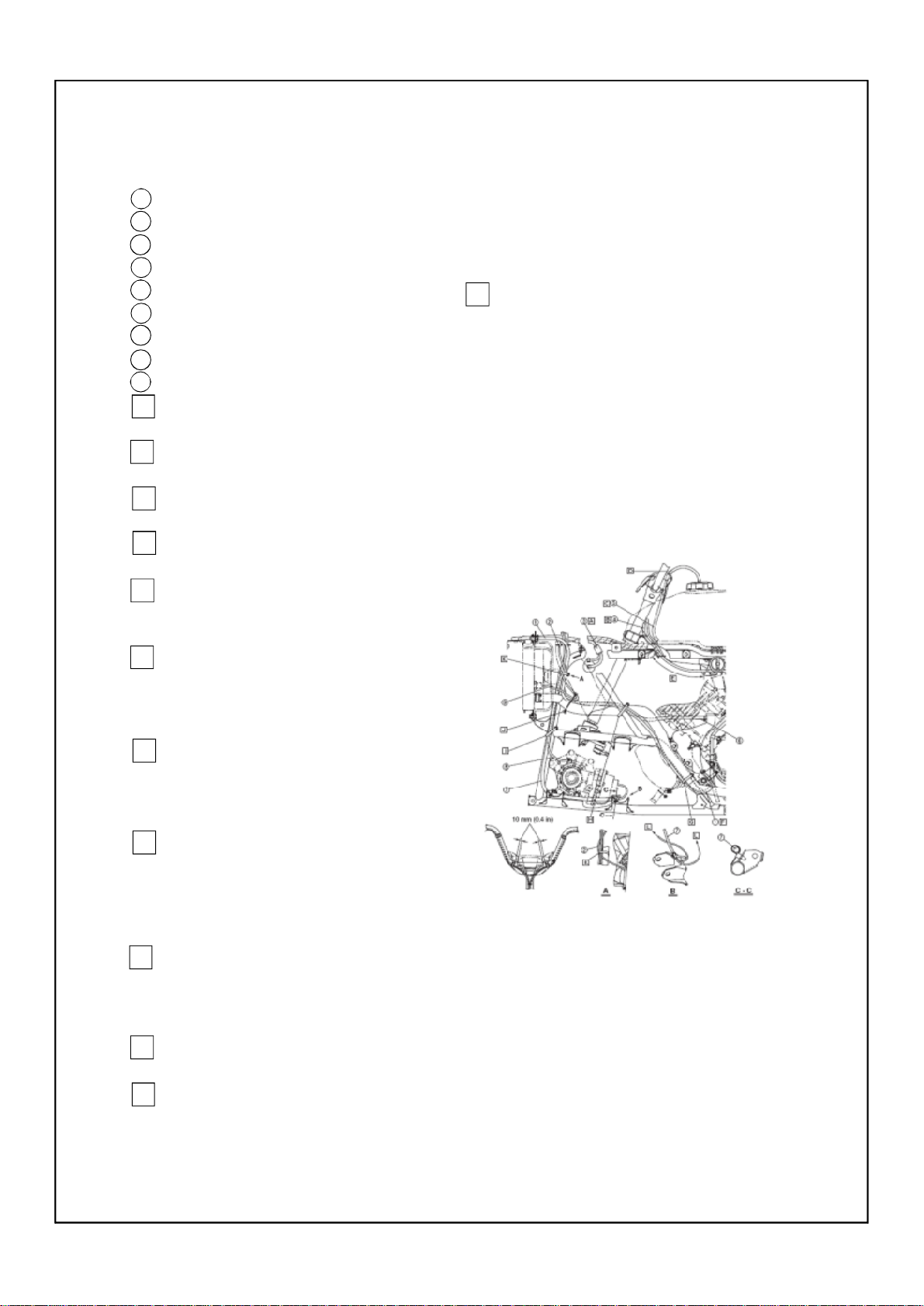
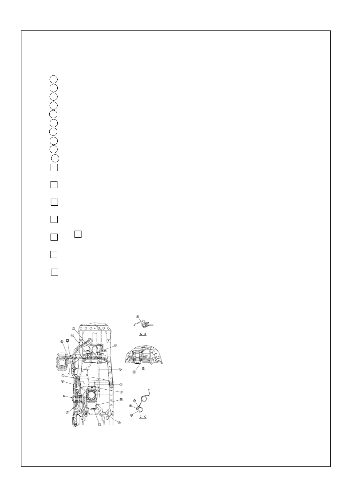
1 Fuel sender lead
2 Differential gear case breather hose
3 Vacuum chamber breather hose
4 Starter motor lead
5 Wireharness
6 Gear position switch lead
7 Final drive gear case breather hose
8 Ground lead
9 Speed sensor lead
10 AC magneto lead
11 Carburetor breather hose
12 Starter cable
13 Fuel hose
14 Thermo switch 1 lead
15 Reverse switch lead
16 AC magneto coupler
17 Gear position switch coupler
18 Speed sensor coupler
19 Radiator fan breather hose
20 Rectifier/regulator lead
21 Water pump breather hose
A Fasten the final drive gear case breather
hose, speed sensor lead, ground lead, gear
position switch lead, AC magneto lead, wire
harness, and reverse indicator light lead with
a plastic locking tie. Be careful not to pinch
the breather hose.
B Fasten the leads in the following order:
ground lead, reverse switch lead, speed sensor lead, gear position switch lead, and AC
magneto lead.
C Pass the final drive gear case breather
hose through the hole in air duct assembly
3.
D To the rear fender
E 70 ~ 90 mm (2.8 ~ 3.5 in)
F Clamp the thermostat assembly breather
hose and carburetor breather hose with the
cable guide.
G Face the coupler release tab upward.
H Pass the vacuum chamber breather hose
through the plastic cover hole.
I Insert a clamp into the third hole from
the top of the rectifier/regulator bracket, and
then clamp the final drive gear case breather
hose with the clamp.
-19-

1 Gear position switch
2 Reverse switch
3 Crankcase breather hose
4 Select lever control cable
5 Rear brake cable
6 Front brake hose
7 Rear brake light switch lead
8 Spark plug lead
9 Fan motor breather hose
10 Fan motor lead
11 Bake fluid reservoir hose
12 Rear brake hose
A Pass the rear brake cable and throttle
cable through the cable guide.
B Pass the rear brake light switch lead and
the main switch lead and auxiliary DC jack
lead over the front fender.
C Clamp the spark plug lead and radiator
inlet hose with a plastic clamp.
D When installing the ignition coil, face
the spark lead to the right side of the frame.
E To the rear fender hole
F Pass the brake light switch lead on the
inside of the rear brake cable and select
lever control cable, and through the cable
guide of the brake master cylinder cover.
-20-
1 Negative battery lead
2 Tail/brake light lead
3 Fuse box
4 Four-wheel drive relay 3
5 Four-wheel drive relay 2
6 Four-wheel drive relay 1
7 Positive battery lead
8 Starter motor lead
9 Wire harness
A Pass the tail/brake light lead through
the lead guide.
B Position the wire harness tape at the end
of the rear fender guide.
C Pass the wire harness through the cable
guide of rear fender.
-21-
1 Front brake hose
2 Throttle cable
3 Thermo switch 1 lead
4 Crankcase breather hose
5 Fuel sender lead
6 Differential gear case breather hose
7 Starter cable
8 Select lever control cable
9 Wire harness
10 Fan motor breather hose
A ass the thermo sensor 1 lead through the
lead guide.
B Pass the crankcase breather hose through
the hose guide.
C Pass the fuel sender lead through the lead
guide.
D Pass the select lever control cable through
the hole of the select lever unit bracket.
E Clamp the starter cable with a plastic
clamp.
F Pass the throttle cable through the cable
guide.
G Fasten the speed sensor coupler, thermo
switch 1 lead, reverse switch lead, ground
lead, gear position switch lead, and AC magneto couplers with a band.
-22-

2.Technical requirement
① In the drawing, the wiring condition and
position for all kinds of wires on the ATV body
is marked. When assembling the finished ATV,
wiring should be done as per the drawing in
principle.
② For the wiring and fixing method which
can’t be marked in the drawing , necessary technical explanation has been made, you should abide
to execute in assembling.
③ For the place of using plastic clip stipu-
lated in the drawing, if can’t be used temporarily,
you can use band to fix it.
④The dimension in the drawing is only used
for reference in operation, while not be used as
checking data. In the details of marking the code
No. of component, the self-carrying component
(wire etc.)of units only be marked with name.
3.Details of relative component
33
32
31
30
29
28
27
26
25
24
23
22
21
20
19
18
17
16
15
14
13
12
11
10
9
8
7
6
5
4
3
2
1
Ser.No.
SSA0-000512-0
SSA0-000511-0
SSA0-000510-0
SSA0-000509-0
150.00-0.39
150.00-03
150.00-06
FG-802000-0
SSA5-320000-0
SSA0-000516-0
SSA0-000515-0
SSA4-230000-0
SSA4-230000-0
SSA4-210000-0
SSA4-220000-0
SSA0-000517-0
SS45-630000-0
FG-803000-0
FG-805000-0
SSA5-510000-0
SSA0-012000-0
Code
Wire clip 4
Wire clip 3
Wire clip 2
Wire clip 1
Cable band
band of steering bar
C.D.I magneto wire
Vent-pipe of carburetor
Cut-off relay
Starting relay
Cable
Ven-pipe of rear brake
Wire of starting motor
High voltage coils and wire
Vent-pipe of battery
Vent-pipe of front
Wire of headlight
Rear brake cable
Wire of handle bar switch
Wire of clutch wire
Throttle cable
Front brake cable units
Wire of mileage meter
Wire of neutral switch
Wire of reverse witch
Overflowig hose of carburetor
Vent-pipe of garbox
Taillight unit
C.D.I
Rectifier
Vent-pipe of gearbox
Main swtich lock
Wire clip unit
Name
3
2
3
2
6
2
1
1
1
1
1
1
1
1
1
1
1
1
1
1
1
1
1
1
1
1
1
2
1
1
1
1
1
Q’ ty
Remark
-23-
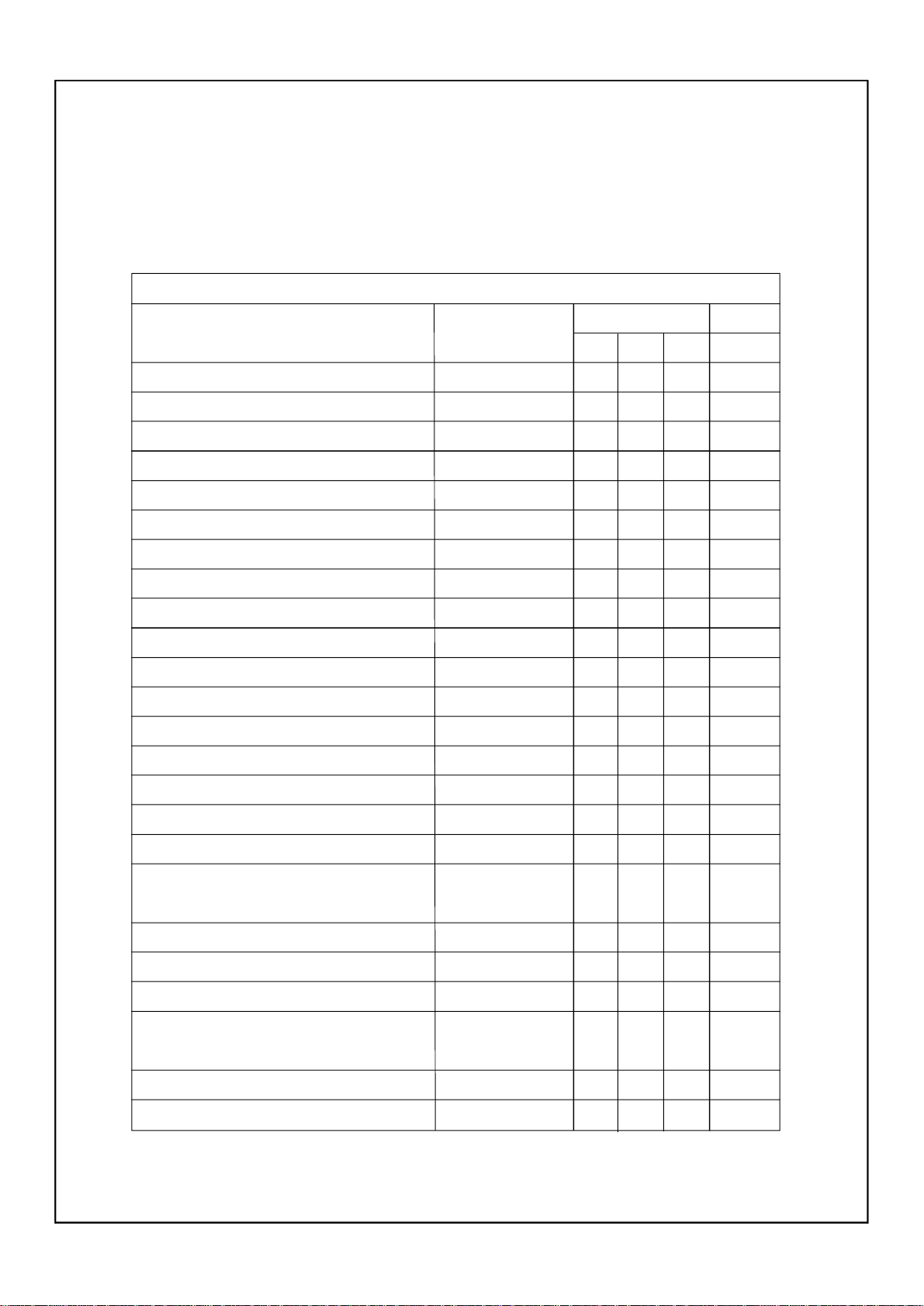
Section 7 Requirements for torque of fastener
(I)ATV body
Torque value of fastener
Part to be tightened
Engine bracket and engine
Engine bracket and rubber damper (front)
Engine bracket and rubber damper (front)
Engine and rubber damper (rear)
Engine and rubber damper (rear)
Rubber damper and frame
Front wheel and front wheel hub
Front wheel hub and constant velocity joint
Front brake disc and front wheel hub
Front brake caliper and front wheel hub
Rear wheel and rear wheel hub
Rear wheel hub and constant velocity joint
Rear brake disc and brake disc hub
Front brake pad holding bolt
Thread size
M8
M8
M6
M10
M6
M10
M10
M16
M8
M8
M10
M16
M6
M10
Tightening torque
Nm
m.kgft.lb
33
33
10
56
10
42
55
200
30
30
55
45
10
18
3.3
3.3
1.0
5.6
1.0
4.2
5.5
20.0
3.0
3.0
5.5
4.5
1.0
1.8
24
24
7.2
40
7.2
30
40
145
22
22
40
32
7.2
13
Remark
Rear brake pad holding bolt
Front brake master cylinder and handlebar
Front brake hose union bolt
Rear brake master cylinder and master cylinder
bracket
Rear brake hose union bolt
Front brake caliper retaining bolt
Front brake caliper bleed screw
Rear brake caliper and drive pinion gear bearing
housing
Rear brake caliper bleed screw
Handlebar holder
-24-
M10
M6
M10
M6
M10
M8
M8
M10
M8
M8
18
27
23
30
23
40
20
1.8
7
0.7
2.7
2.3
3.0
2.3
6
0.6
4.0
6
0.6
2.0
13
5.1
19
17
22
17
4.3
29
4.3
14
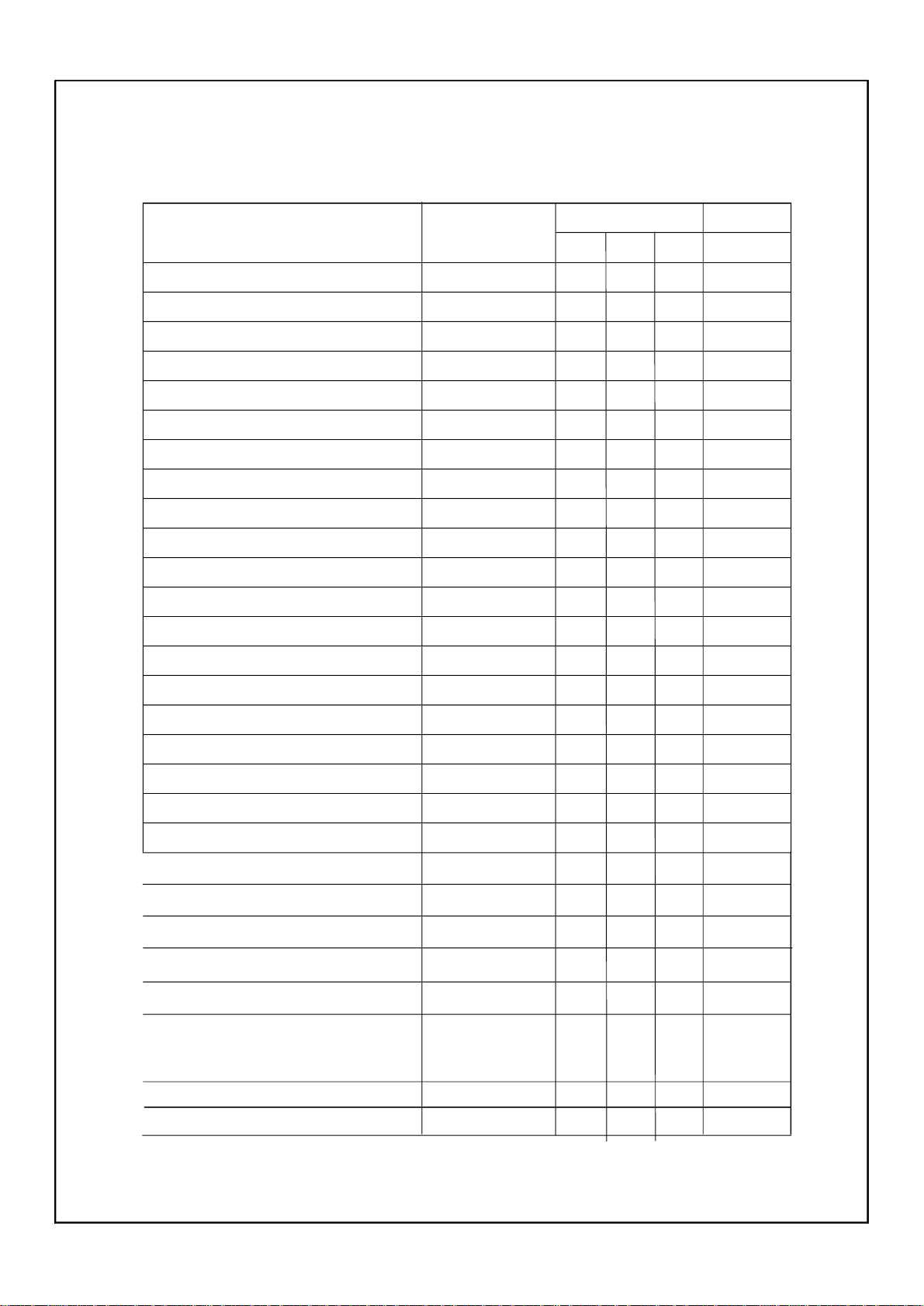
Part to be tightened Thread size
Tightening torque
Nm
m.kgft.lb
Remark
Steering stem bearing retainer
Steering stem and pitman arm
Steering stem and frame
Pitman arm and tie-rod
Steering knuckle and tie-rod
Steering knuckle and front arm (upper)
Steering knuckle and front arm (lower)
Steering knuckle and brake disc guard
Steering knuckle and brake hose holder
Front shock absorber and frame
Front shock absorber and front arm (upper)
Front arm (upper) and frame
Front arm (lower) and frame
Stabilizer and frame
Stabilizer joint and stabilizer
Stabilizer joint and rear frame
Rear knuckle and rear frame (upper)
Rear knuckle and rear frame (lower)
Rear shock absorber and frame
Rear shock absorber and rear arm (lower)
Rear arm (upper) and frame
Rear arm (lower) and frame
Differential gear case and frame
M42
M14
M8
M10
M10
M10
M10
M6
M6
M10
M10
M10
M10
M8
M10
M10
M10
M10
M10
M10
M10
M10
M10
40
180
23
25
25
25
48
7
10
45
45
45
45
30
48
48
45
45
45
45
45
45
55
4.0
18.0
2.3
2.5
2.5
2.5
4.8
0.7
1.0
4.5
4.5
4.5
4.5
3.0
4.8
4.8
4.5
4.5
4.5
4.5
4.5
4.5
5.5
29
130
17
18
18
18
35
5.1
7.2
32
32
32
32
22
35
35
32
3.2
32
32
32
32
40
Differential gear case filler bolt
Differential gear case drain bolt
Differential gear case cover and differential gear
case
Gear motor and differential gear case cover
Universal joint yoke and drive pinion gear
M14
M14
M8
M8
M14
23
10
25
13
62
2.3
1.0
2.5
1.3
6.2
16
7.2
18
9.4
45
-25-
 Loading...