

Page 1

HSM FP3000
Barrel Crusher
Instruction Manual
Page 2
GB
PRODUCT
SERVICE
Keep this instruction for future use!
OPERATING INSTRUCTIONS
BARREL PRESS
HSM FP 1500
HSM FP 3000
6.817.999.520 - Edition 03/2000
Page 3

HSM - Pressen GmbH + Co.KG,
Bahnhofstraße 115,
88682 Salem, Germany
Tel. ++49 (0) 75 53/822-0
Fax ++49 (0) 75 53/ 82 21 60
e-mail: info@hsm-online.de
Keep this instruction for future use!
6.817.999.520 - Edition 03/2000
Page 4

FP 1500 Contents
FP 3000
1 Introduction
1.1 About this documentation 1-1
1.2 Nameplate and machine number 1-2
1.3 Copyright 1-2
1.4 Explanations 1-3
1.5 Pictograms 1-4
2 Safety
2.1 Use according to instructions 2-1
2.2 Selection and qualificationof staff 2-2
2.3 Organisational measures 2-3
2.4 Handling the barrel press 2-3
2.5 Maintenance and repair 2-4
2.6 Environmental protection 2-5
2.7 Checklist for checking the safety devices 2-5
3 Description
3.1 Short description of baling presses 3-1
3.2 Technical data 3-2
3.3 Description of operating elements 3-5
4 Transport
4.1 Transport information 4-1
4.2 Transport to a different operating site 4-2
5 Installation
5.1 General information 5-1
5.2 Installing the barrel press 5-2
5.3 Start-up at installation site 5-3
5.4 Move cylinder into position 5-4
Edition 03/2000 6.817.999.520
I
Page 5

Contents FP 1500
FP 3000
6 Working with the barrel press
6.1 Normal operation 6-1
6.2 Operation outdoors 6-2
7 Troubleshooting 7-1
8 Maintenance
8.1 General information 8-1
8.2 Oil level/venting lid 8-2
8.3 Changing the hydraulic oil 8-3
8.4 Cleaning the hydraulic oil tank 8-4
8.5 Lubricating moving parts 8-5
9 Replacing components 9-1
10 Waste disposal information 10-1
11 Wiring diagrams 11-1
12 Hydraulic diagram 12-1
6.817.999.520 Edition 03/2000II
Page 6

1 Introduction
1.1 About this documentation
The purpose of this Operating Manual is to assist you in the operation of the barrel
press in accordance with the intended use. It contains important information for the
safe, expert and economical operationof the barrel press. Observing this Operating
Manual helps to prevent danger, to reduce repair costs and downtime and to improve
the reliability and service life of the barrel press.
The Operating Manual must always be available to the personnel.
The Operating Manual must be read and used by all persons who work with and on
the barrel press, e.g. with the following:
– Operation, including set-up, troubleshooting, disposal of production waste,
disposal of operating and auxiliary materials
FP 1500 Introduction
FP 3000
– Maintenance (maintenance, inspection, repair)
– Transport
In addition to this Operating Manual and the compulsory accident prevention
regulations in the user country and at the installation location, the recognised
technical rules for operation according to safety and technical practices must be
observed.
Please contact your local dealer if you still have questions after reading this
Operating Manual.
HSM - Pressen GmbH + Co. KG
reserve the right to perform any changes and modifications which are deemed
necessary. However, this does not imply the obligation for a subsequent modification
of already delivered machines.
Design and technical modifications as compared to the representations and statements
in this Operating Manual are reserved.
This Operating Manual was established with consideration of the EC directives.
permanently aspire to improve their products. They
Edition 03/2000 6.817.999.520
1 - 1
Page 7

Introduction FP 1500
FP 3000
1.2 Nameplate and machine number
HSM-Pressen GmbH+CoKGHSM-Pressen GmbH+CoKG
Postfach 1163Postfach 1163
D-88 678 SalemD-88 678 Salem
West Germany West Germany
MODELL
MASCH.-NR.:
PRESSKRAFT: kN
SPANNUNG: V Hz
BAUJAHR:
The machine number is specified on the nameplate of the barrel press, shown above.
Guarantee claims and inquires cannot be processed if you do not quote the machine
number.
Please therefore enter this number in the grey field on the nameplate immediately
after receipt of the barrel press.
1.3 Copyright
We own the copyright to this Operating Manual. It is issued only to purchasers of our
machines.
Without our permission, these documents may neither be reproduced nor issued to
third parties, in particular to competitors. This applies also to extracts from this
documentation.
LEISTUNG: kW
NENNSTROM: A
1 - 2
6.817.999.520 Edition 03/2000
Page 8

1.4 Explanations
The header and footer contain the following information concerning this Operating
Manual:
– Chapter headline
– Type
– Identification number of Operating Manual
– Date of edition
– Specification of chapter and page
Control elements
FP 1500 Introduction
FP 3000
The designations of the control elements are marked with double quotes in this
manual. When a figure containing the mentioned control element is referred to in the
text, the item number is indicated following the designation.
Example: "Standby light symbol" (3-4/2).
Figure legends and item numbers
figures have consecutive numbers. Important system or machine parts shown on the
figure have an item number.
In the legend to the figure, the machine parts are listed in the sequence of the item
numbers. When a figure is referred to within the text, the machine part can be easily
found used the specified chapter number, figure number and item number.
Example: (3-4/2) means chapter 3 - figure 4 / item number 2.
Edition 03/2000 6.817.999.520
1 - 3
Page 9
Introduction FP 1500
☞
FP 3000
1.5 Pictograms
The following symbols (pictograms) are used in this Operating Manual for especially
important information.
➪ This arrow prompts the user for an action.
Safety information
This pictogram marks information on damage prevention for the user.
Note
This pictogram marks special characteristics of the barrel press.
Assembly and installation information
This pictogram marks information on the assembly of single parts and
assemblies.
Functional information
Special characteristics in the operation or handling of the barrel press
are pointed out.
Maintenance information
This pictogram marks special characteristics in maintenance for the
operator (e.g. a special tool to be used).
Environmental information
1 - 4
This pictogram marks environmental regulations for the operator (e.g.
water act, waste act).
6.817.999.520 Edition 03/2000
Page 10

FP 1500 Safety
FP 3000
2 Safety
2.1 Use according to instructions
The barrel press FP 1500 is intended only for compacting empty light sheet metal
barrels as well as any other materials specified in the contract.
The barrel press FP 3000 is intended only for compacting empty light sheet metal
barrels and empty rolling hoop drums as well as any other materials specified in
the contract.
Warning
Explosive danger!
You can be severely insured by spreading metal parts and splinters.
Do not press
- containers of highly inflamable or explosive goods
- containers under pressure
Any other use beyond the scope described here is regarded as not being in
accordance with the instructions.
The manufacturer will not be made liable for damage resulting from incorrect use.
The assembly, dismantling, re-assembly, start-up, operation and maintenance work
specified by the manufacturer must be observed.
Irrespective of the laws and regulations mentioned in this Operating Manual, the
appropriate national laws and regulations which are valid for the operator must be
observed.
The customer service of HSM must be consulted before the barrel press is used
outside its contractually agreed and intended scope of application otherwise the
manufacturer's warranty will become void.
The barrel press has been inspected for safety by the Berufsgenossenschaft Druck
und Papier (mutual indemnity association print and paper processing).
However, improper operation and misuse endanger:
• the health and life of the user
• the barrel press and other valuable equipment of the operator
• the efficient performance of the barrel press.
Edition 03/2000 6.817.999.520
2 - 1
Page 11

Safety FP 1500
FP 3000
2.2 Selection and qualification of staff
The barrel press employs state-of-the-art technology. However, this machine can
become hazardous if used incorrectly or for purposes other than those for which it
was designed.
– The barrel press may only be operated, serviced and repaired by authorized,
trained and instructed personnel.
– Each person given duties of assembling, dismantling and reassembling and
maintenance (inspection, servicing, repair) of the barrel press must have read and
fully understood the entire Operating Manual, in particular the "Safety" section
before starting to work. We suggest the management obtains written confirmation
in particular from personnel only working occasionally with the barrel press.
– The management has the obligation to instruct the personnel in handling the barrel
press and to create binding instructions. The operating and maintenance personnel
must receive regular training on safety regulations.
– The responsibilities of the staff for assembly, dismantling and reassembling, start-
up, operation and maintenance must be clearly delegated and observed.
– Persons to be trained or instructed may operate the barrel press only under the
permanent supervision of an experienced person.
– The barrel press may not be operated by persons under 16 years of age.
– Work on the electrical system of the barrel press may only be performed by a
qualified electrician or by instructed persons under instruction and supervision of
a qualified electrician according to the electro-technical rules.
– Only persons with specialist knowledge and experience with hydraulics may work
on the hydraulic equipment.
6.817.999.520 Edition 03/20002 - 2
Page 12

2.3 Organisational measures
– The Operating Manual must always be available to the personnel.
– All safety and danger information on the barrel press must be kept complete and
legible.
– In addition to the Operating Manual the generally recognised legal and other
binding regulations concerning accident prevention and environmental protection
must be observed.
– The barrel press must not be modified or converted without prior approval from the
manufacturer.
– Only use original spare parts.
FP 1500 Safety
FP 3000
2.4 Handling the barrel press
– Always work according to the instructions.
– Before switching on and starting the barrel press, ensure that nobody is jeopardized
by the operation of the barrel press.
– Operate the barrel press only when all protective devices and safety-technical
equipment have been installed and are operative. Do not make any conversions
or modifications on your own initiative.
– In normal operation, open the loading flap and the bale ejection door only when
the hydraulic cylinder is idle.
– Check the barrel press at least once per shift for externally visible damage and
defects.
– Ensure that the barrel press workplace is always clean and safe.
– Immediately shut down and secure the barrel press when malfunctions occur.
– Immediately report any changes in the the operational behaviour to the competent
person. Shut the machine down and secure it, if necessary.
– Wear your personal safety clothes during operation.
– Observe the relevant safety and environmental regulations (e.g. hazardous
material act, waste act, water act) when handling hazardous materials.
Edition 03/2000 6.817.999.520
2 - 3
Page 13

Safety FP 1500
FP 3000
2.5 Maintenance and repair
– Work on the electrical system of the barrel press may only be performed by a
qualified electrician or by instructed persons under instruction and supervision of
a qualified electrician according to the electro-technical rules.
Mechanical maintenance and repair work
➪ Switch off main switch and secure against switching on again.
➪ Pull mains plug.
– Mechanical and hydraulic functional elements must be inspected by qualified staff
for correct function and wear every six months.
– Check whether all protective devices have been re-installed before putting the
machine into operation again after repairs.
Electrical maintenance and repair work
➪ Switch off main switch and secure against switching on again.
➪ Pull mains plug.
– All electrical functional elements and components must be inspected by a qualified
electrician every six months.
– All connecting cables must be laid in such a way that they cannot be tripped over.
– Check whether all protective devices have been re-installed before putting the
machine into operation again after repairs.
Oils, greases and other chemical substances
– When handling oils, greases and other chemical substances observe the safety
regulations which are applicable for these products. The relevant DIN safety data
sheets are provided by the respective supplier.
6.817.999.520 Edition 03/20002 - 4
Page 14

FP 1500 Safety
FP 3000
Hydraulic system
– Only persons with specialist knowledge and experience with hydraulics may work
on the hydraulic equipment.
– All lines, hoses and screw joints must be regularly inspected for tightness and
visual evidence of damage. Observe the safety regulations for hydraulic hoses.
Spurting oil can cause injuries and fires.
– The hoses must be immediately replaced when defects are determined during the
check.
– Any system sections and pressurized lines which can be opened must be de-
pressurized according to the hydraulic diagram before repair work begins.
2.6 Environmental protection
– Observe the applicable environmental legislation for all work on and with the barrel
press.
– Dispose of waste oil and resiudal fluids from the compressed material in a correct
manner. These substances may neither be disposed of via the drainage system
nor be allowed to permeate into the ground.
– Observe the safety data sheet according to DIN 52 900 when using cleaning
agents and solvents. This data sheet contains the physical, safety-technical,
toxicological and ecological data which are essential when handling chemical
substances. In addition it contains recommendations for the safe storage, handling
and transport of these substances.
2.7 Checklist for checking the safety devices
when • at the start of each work shift (when operation is sporadic)
• at least once a week in continuous operation
• after each maintenance or repair
for • specified condition • safe attachment
• specified location • specified function
Copy the following checklist for the regular checks.
Edition 03/2000 6.817.999.520
2 - 5
Page 15
Safety FP 1500
FP 3000
Checklist for the safety devices
Check off the individual points when they are in order. ✔
Operate the barrel press only when all points have been checked and are in order.
Check the function of the safety switch on the
loading door.
When you open the loading door while the barrel
press is in operation, the barrel press must
immediately switch off. It must be impossible to
switch the barrel press on while the loading door
is open. After closing the loading door, it must be
possible to switch the barrel press on again.
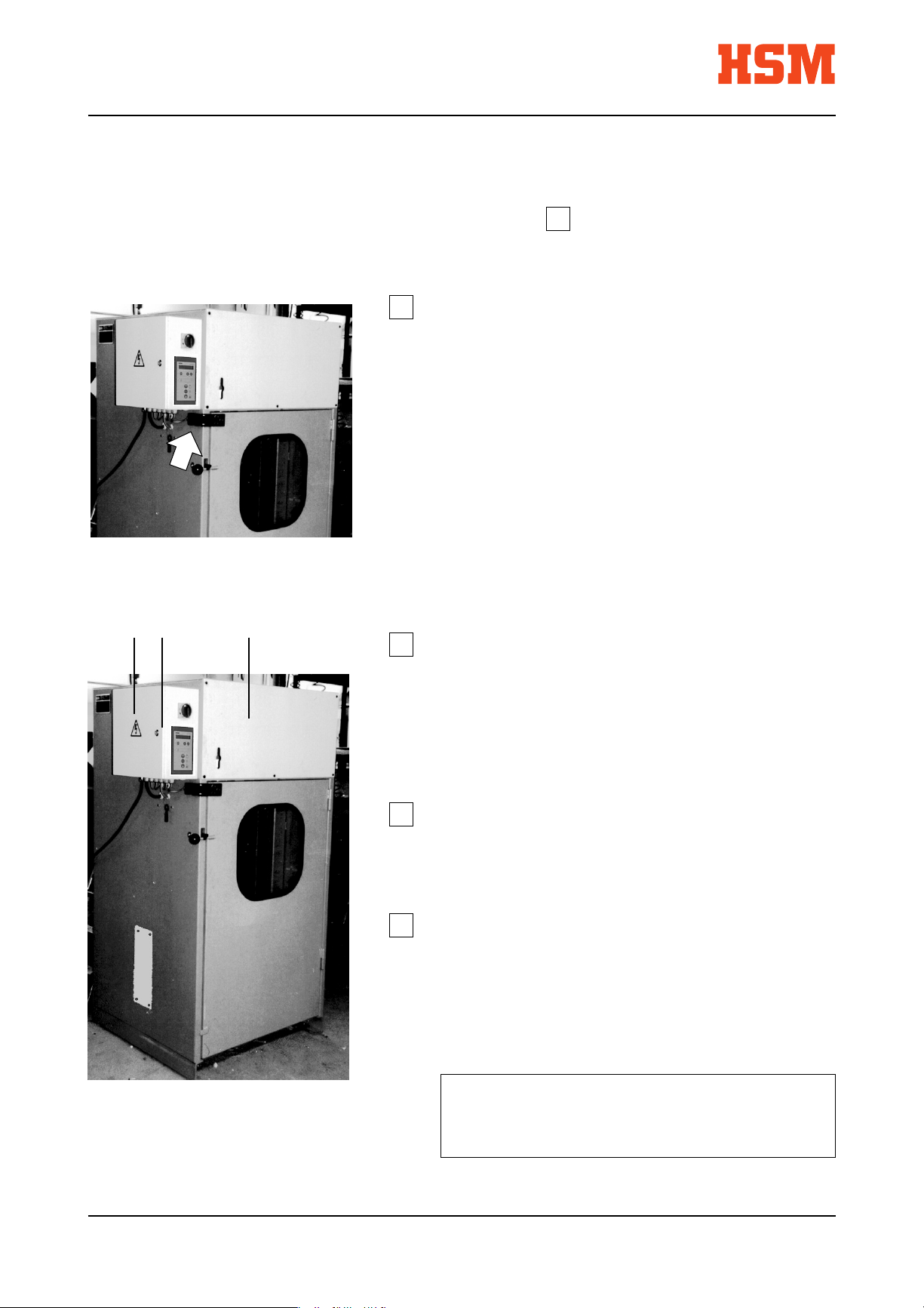
1 2 3
All protective covers must be installed and
screwed tight.
• front cover (3)
• rear cover
• rear panel
The control cabinet (2) must be closed.
The warning sign with the lightning symbol (1)
must be attached at the indicated position.
Checked
........................... .......................................................
Date Signature
6.817.999.520 Edition 03/20002 - 6
Page 16

FP 1500 Description
FP 3000
3 Description
3.1 Short description of barrel presses
The barrel press FP 1500 is intended only for compacting empty light sheet metal
barrels as well as any other materials specified in the contract.
The barrel press FP 3000 is intended only for compacting empty light sheet metal
barrels and empty rolling hoop drums as well as any other materials specified in
the contract.
Consult the customer service of HSM if you plan to use the barrel press outside its
contractually agreed and intended scope of application.
Technical characteristics • short cycles
• usable indoor and outdoor
• collecting basin for residual liquid
• electro-hydraulic drive
• membrane keypad with LED-display
• automatic return stroke
• press ram on roller bearings
• press ram with spikes for barrel opening
• piston rod hard-chrome plated
• almost maintenance free
• enclosed construction with inspection window
• welded frame
Edition 03/2000 6.817.999.520
3 - 1
Page 17

Description FP 1500
FP 3000
3.2 Technical data
Machine characteristics FP 1500 FP 3000
Total weight approx. 720 kg approx. 990 kg
Press data
Pressing power 180 kN 280 kN
Pressing time with return stroke 16 s 31 s
Max. height of barrel 932 mm 1092 mm
Max. diameter of barrel 618 mm 618 mm
Type of barrel light sheet metal rolling hoop
light sheet metal
Motor data
Rated power P
n
7,5 kW 7,5 kW
Operating voltage U 400 V 200 V
Frequency f 50 Hz 50 or 60 Hz
Rated current I
Output RPM n
n
out
14.5 A 25.3 A
3000 min
-1
3600 min
Protection mode IP54 IP54
Hydraulic system
Pump
Discharge Q with 3000 min
Operating pressure p
Operation
-1
41.4 l/min
210 bar
Oil tank
Volume 27 l
Oil type Multigrade oil (DIN 51524-T3)
ISO viscosity class HVLP 22
-1
6.817.999.520 Edition 03/20003 - 2
Page 18
FP 1500 Description
FP 3000
Colour
Frame orange RAL 2008
Covers grey-white RAL 9002
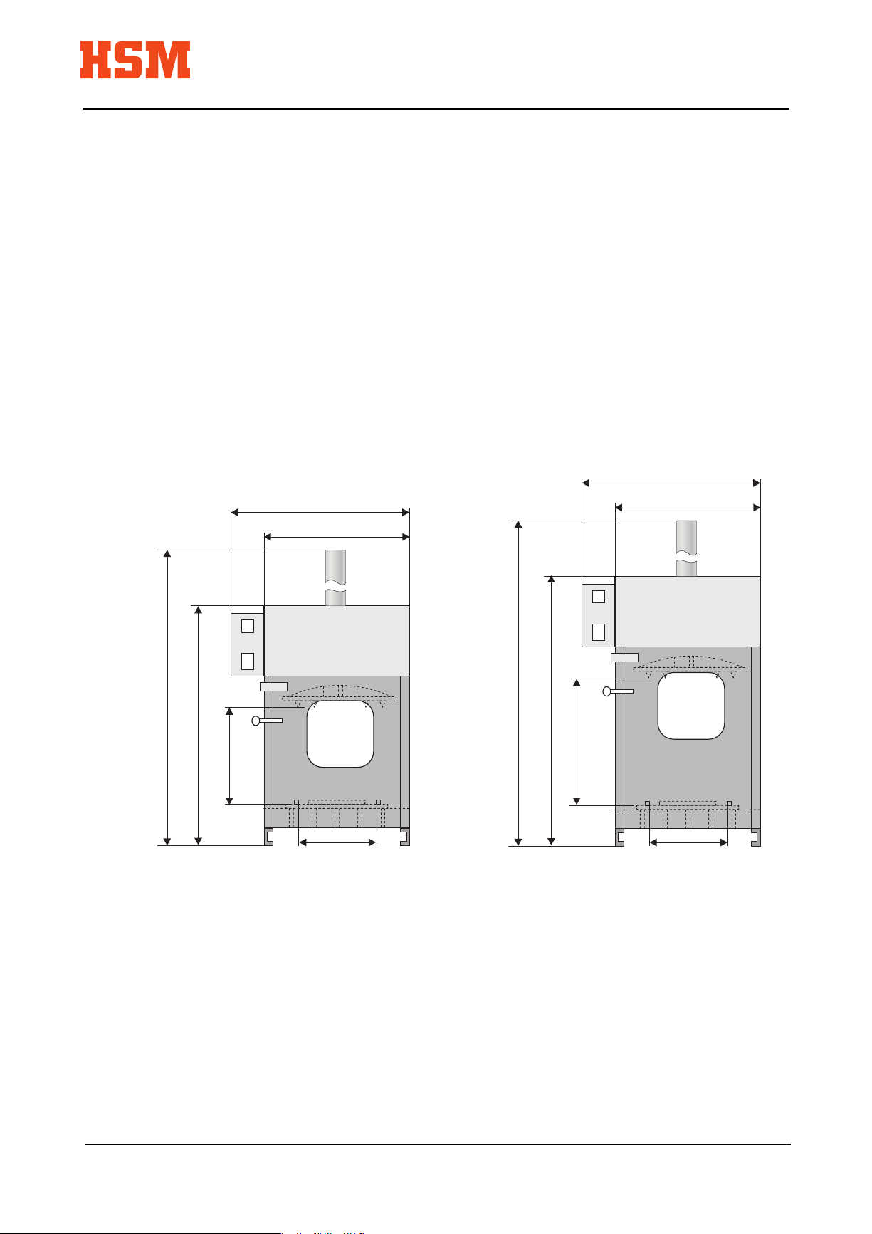
Machine dimensions
(ready for operation) FP 1500 FP 3000
Width 1168 mm 1168 mm
Depth 960 mm 960 mm
Max. height 2430 mm 2892 mm
2430
1785
932
1168
963
618
1168
963
2892
1917
1092
618
Fig. 3-1 FP 1500 Fig. 3-2 FP 3000
Edition 03/2000 6.817.999.520
3 - 3
Page 19

Description FP 1500
FP 3000
Space requirements FP 1500 FP 3000
Width 2180 mm 2180 mm
Depth 1980 mm 1980 mm
Height 2430 mm 2892 mm
ca. 2180
ca. 960
ca. 1980
Fig. 3-3 Top view FP 1500 / FP 3000
Power requirements and fuse protection (3 x 400 V / 50 Hz) (2 x 200 V / 50 Hz)
Total rated power P
Total rated current I
n
n
7.5 kW 7.5 kW
14.5 A 25.3 A
Total fuse protection 25 A (slow) 35 A (slow)
Mains plug CEE 32 depending on country
Noise emission values
The barrel press has the following values for the sound pressure level according to
DIN 45635 Section 27:
Idle 1 m / 7 m *) 75,2 / 70,2 dB (A)
Full load 1 m / 7 m *) 79,8 / 75,2 dB (A)
*) Distance measured between measuring instrument and machine surface at the hopper.
6.817.999.520 Edition 03/20003 - 4
Page 20

FP 1500 Description
FP 3000
3.3 Description of operating elements
I
1
0
0
HSM Pressen GmbH + Co.KG
ELECTRONIC
7
2
3
8
4
5
0
6
Fig. 3-4 Control panel
1 Main switch
2 Standby (Ready for operation)
3 Malfunction
4 Raise press ram
5 Press ram stop
6 Lower press ram
7 no function
8 no function
Edition 03/2000 6.817.999.520
3 - 5
Page 21

Description FP 1500
FP 3000
I
0
0
Main switch (1)
When turned 90° clockwise, the main switch is on.
The main switch can be locked in the
"Off"
position with a padlock.
Light symbol "Standby" (2)
This message is displayed when the main switch is switched on and under power.
This message is flashing if the door is open.
Light symbol "Malfunction" (3)
This message is displayed when there is any malfunction on the barrel press. The
symbol flashes at the malfunctions "Wrong direction of rotation" and "Phase is
missing".
The barrel press cannot be started as long as this message is displayed!
(-> see section "Malfunctions")
"Raise press ram" key (4)
When this soft-key is pressed, the press ram returns into its upper end position with
the door closed.
"Press ram stop" key (5)
With this soft-key the press ram can be stopped in any position.
The movement can be continued by pressing the "Raise/lower press ram" softkey.
"Lower press ram" key (6)
Pressing this soft-key while the door is closed starts the compression. The press ram
moves down and compresses the material.The press ram automatically returns into
its upper end position after expiry of the pressing time.
6.817.999.520 Edition 03/20003 - 6
Page 22

4 Transport
4.1 Transport information
The barrel press must be transported in vertical position.
Transport means
Use adequately dimensioned transport means (lorry, crane, fork-lift) for
transport and installation of the barrel press.
The suspension must be designed for at least 750 kg (FP 1500) or
1000 kg (FP 3000).
Machine centre of gravity
The press ram must be in the bottom position (moment of tilt). The centre
of gravity is then in the bottom half of the barrel press.
FP 1500 Transport
FP 3000
Apply the hoists at the specified positions (Fig. 4-1) only.
Fig. 4-1 Pick-up points for transport
A fork-lift truck can also be used for transport to the installation site.
Safety regulations
Observe the relevant safety regulations and the valid accident prevention
regulations.
Edition 03/2000 6.817.999.520
4 - 1
Page 23

Transport FP 1500
☞
FP 3000
Transport damage
If damage is determined after unloading when accepting the delivery,
HSM and the forwarding company must be informed immediately. If
necessary, an independent expert must be contacted immediately.
➪ Remove packing and transit clamps.
➪ Dispose of packing in an ecologically beneficially manner.
4.2 Transport to a different operating site
When the barrel press is transported to a different operating site, there may be no
compression material in the barrel press. Ensure that the load on the foundation is
accounted for (5.1) and the space requirements fulfilled at the new installation site
(3.2). An approved electrical connection must be available at the new installation site.
Qualified personnel
Installations on the electrical system or on the control cabinet may be
performed only by a qualified electrician or our customer service.
The following must be observed for transport to a different operating site:
• Transport with press ram in bottom position (moment of tilt)
• Transport with lowered cylinder (transport height).
6.817.999.520 Edition 03/20004 - 2
Page 24

FP 1500 Transport
☞
FP 3000
Transport with press ram in bottom position
Für transport within a plant it is normally sufficient to move the press ram into bottom
position to shift the centre of gravity of the barrel press. It must be checked that the
cylinder projects at the top (see Fig. 3-1).
➪ Move press ram into bottom position by pressing the "Lower press ram" soft-key.
➪ Press the "Press ram stop" soft-key when the bottom position is reached.
➪ Switch off the main switch.
➪ Take out the collecting basin for residual liquid and dispose the residual liquid in
an ecologically beneficially manner.
➪ Disconnect the current supply from the mains.
The barrel press can be transported to a different operating site when the transport
information (Section 4.1) is observed.
Transport with lowered cylinder
If vertical transport is not possible due to the projecting cylinder, the cylinder can be
retracted by loosening the cylinder flange (see Section 5.4).
➪ Put a timber on the bottom plate
• Height for timber - FP 1500: 350 mm
• Height for timber - FP 3000: 320 mm
Transport information
The timber's height has to be considered, otherwise the hydraulic hoses
can be teared off whilst lowering the hydraulic cylinder.
➪ Move press ram down by pressing the "Lower press ram" soft-key.
➪ Press the "Press ram stop" soft-key when the timber is reached.
Edition 03/2000 6.817.999.520
4 - 3
Page 25

Transport FP 1500
FP 3000
2
1
Fig. 4-2 Attachment of cylinder flange
1 Dowel pins
2 Screws
➪ Loosen and remove the screws on the cylinder flange.
➪ Press the "Raise press ram" soft-key. The cylinder must move down.
Assembly information
If the cylinder does not move down check whether the dowel pins
became loose all screws were removed or the cylinder is hooked on the
hydraulic hose.
➪ Lower the cylinder step by step until it has reached the desired transport height.
➪ Switch the main switch off.
➪ Take out the collecting basin for residual liquid and dispose the residual liquid in
an ecologically beneficially manner.
➪ Disconnect from the mains.
The barrel press can be transported to a different operating location when the
transport information (Section 4.1) is observed.
6.817.999.520 Edition 03/20004 - 4
Page 26

☞
5 Installation
5.1 General information
Qualified personnel
We urgently recommend to have the installation work on the barrel press
performed by trained HSM personnel. We assume no responsibility for
damage arising from incorrect installation work.
Installation site
When determining the installation site consider the space required for maintenance
and inspection work on the barrel press (see Section 3.2).
FP 1500 Installation
FP 3000
The barrel press may only be operated in dry locations.
Installation outdoors
Attach a protection against rain water when the barrel press is operated
outdoors. The power supply must fulfill the requirements for installation
outdoors (additional FI protection).
Environmental information
Residual liquid should not come into the earth.
Keep to the environmental regulations
No special foundation is required. Check the carrying capacity of the ground if doubts
exist.
Supply connections
The barrel press is supplied ready for connection with the appropriate connecting
cable and plug.
A suitable CEE socket must be present at the installation site.
Edition 03/2000 6.817.999.520
5 - 1
Page 27

Installation FP 1500
FP 3000
Adjustments
The various components and the electrical and hydraulic systems are set by HSM
before delivery.
Operational safety
Unauthorized modifications of the set values are not allowed and can
result in severe damage to the machine.
5.2 Installing the barrel press
Installation personnel
All installation work may be performed only by trained persons who act
on behalf of the operator. The valid accident prevention regulations and
VBG 4, 5 and 15 as well as DIN VDE 0105 Part 1 must be complied with.
➪ Place barrel press at installation site on an even, smooth floor.
➪ Level off a possible unevenness of the floor with metal shims.
➪ Open the door an take out the collecting basin for residual liquid.
Assembly and installation information
The closing screw at the front of the collecting basin can be unscrewed
with an Allan key. By this the collecting basin can be emptied without
being removed off the guding.
6.817.999.520 Edition 03/20005 - 2
Page 28

FP 1500 Installation
FP 3000
➪ Put the collecting basin into the guiding under the door. (Fig. 5-1)
Fig. 5-1 Guding collecting basin
➪ The on-site power supply must be installed by a qualified electrician.
➪ The protective devices must be fully installed before start-up.
Checking the protective devices
All protective devices must be checked for their effectiveness by a
person acting on behalf of the operator. Use the checklist for the safety
devices (Section 2.7).
5.3 Start-up at installation site
Checking the direction of rotation
Check the direction of rotation of the motor before the first start-up.
➪ Insert the CEE plug in the on-site socket.
➪ Switch on the main switch.
When the phases of the on-site power supply are incorrectly connected this is
signalled by the "Malfunction" light symbol .
-> see section "Malfunctions"
Edition 03/2000 6.817.999.520
5 - 3
Page 29

Installation FP 1500
FP 3000
5.4 Move cylinder into position
The cylinder is retracted during transport and must be moved into operating position
and connected with dowels and screws before the first compression.
➪ For a better control, unscrew the front cover above the door.
Risk of squeezing
Do not reach into the unprotected parts of the barrel press as long as the
covers are removed.
➪ Press the "Lower press ram" soft-key.
• Ensure that the cylinder end and the hoses which are visible on top of the
machine move up.
• If the cylinder does not move it is possible that the door is open.
➪ Move up the cylinder in several steps.
➪ In the meantime, open the door and check the position of the cylinder flange. Do
not operate under pressure before the cylinder is screwed tight.
Assemblyinformation
The cylinder is not secured against turning. The hydraulic hoses or the
fittings on the cylinder can be damaged whilst moving.
➪ Permanently control the position of the cylinder and the hydraulic hoses.
➪ Press the "Lower press ram "soft-key until the cylinder flange has reached the
upper housing frame.
Stop cylinder movement
Immediately press the "Press ram stop" soft-key when the cylinder
flange has reached the upper housing frame.
6.817.999.520 Edition 03/20005 - 4
Page 30

FP 1500 Installation
FP 3000
Do not operate under pressure because the timber will be squeezed.
Installation information
The glued adjusting plates on the cylinder flange must not be removed.
➪ Open the door and adjust the cylinder flange to the tapped holes on the upper
housing frame.
➪ Tap the dowel pins (5-2/1) into the bore holes on the upper housing frame.
➪ Screw in the supplied screws (5-2/2) and tighten them with a torque spanner.
FP 1500 M 16x50 (8.8) 195 Nm
FP 3000 M 20x70 (8.8) 395 Nm
2
1
Fig. 5-2 Fastening of flange
1 Dowel pins
2 Screws
➪ Now close the door and move the press ram into the upper end position.
➪ Re-install all unscrewed covers.
➪ Take the timber out of the press.
The barrel press is now ready for operation.
Edition 03/2000 6.817.999.520
5 - 5
Page 31

Installation FP 1500
FP 3000
6.817.999.520 Edition 03/20005 - 6
Page 32

FP 1500 Working
FP 3000 with the barrel press
6 Working with the barrel press
6.1 Normal operation
Starting the barrel press
➪ Switch the main switch on.
➪ Check all protective devices using the checklist (see Section 2.7).
The barrel press is now ready for operation.
Operation
➪ Put the barrel into the barrel press.
➪ Ensure that the barrel stands inside of the three buffers on the bottom plate.
➪ Close the door
➪ Press the "Lower press ram" soft-key.
Functional information
The press ram moves downwards. The press ram automatically switches
over and moves back into start position after the press time has elapsed.
➪ Take out the pressed material and refill the barrel press.
Environmental information
Dispose residual liquid in the basin by environmental regulations.
Edition 03/2000 6.817.999.520
6 - 1
Page 33

Working FP 1500
with the barrel press FP 3000
Shutting down the barrel press
➪ Close the door
➪ Move the press ram completely down and stop it with the "Press ram stop" soft-
key.
➪ Switch off the main switch.
➪ Secure the main switch against unauthorized switching on.
6.2 Operation outdoors
Some special points must be observed here:
Special supervisory obligations
Put into operation only under supervision.
The operator must ensure that unauthorized persons do not have
access to the barrel press.
When the barrel press is not operated it must be shut down and secured
against unauthorized use.
– The barrel press must not be directly exposed to rain.
Environmental information
Residual liquid should not come into the earth.
Keep to the environmental regulations
– The maintenance intervals must be reduced.
– If the temperature drops below 0°C, use hydraulic oil with a suitable viscosity, if
required.
6.817.999.520 Edition 03/20006 - 2
Page 34

7 Troubleshooting
Reaction to malfunctions
When a malfunction occurs, the cause must be determined and corrected.
Immediately put the barrel press out of operation. Please observe the
"Safety" section for troubleshooting.
Qualified personnel
Troubleshooting often requires special knowledge and must therefore
only be performed by qualified personnel.
FP 1500 Troubleshooting
FP 3000
As soon as there is any malfunction on the baler, the read light symbol is displayed.
The barrel press cannot be started as long as the red light symbol is displayed!
Possible cause What to do
Phase is missing Electrician! Check onsite fuses.
Incorrect connection of phases / Wrong direction of rotation Electrician! Check rotatory field
Oiltemperature too high Let oil cool down
Sensing device for oiltemperature defective Electrician! Change sensing device
Motor protective switch has swapped Motor too hot! Let motor cool down
Door switch defective Switch / Switching mechanism -> Contact service of HSM
Limit switch for "Press ram on top" defective Switch / Switching mechanism -> Contact service of HSM
Edition 03/2000 6.817.999.520
7 - 1
Page 35

Troubleshooting FP 1500
FP 3000
6.817.999.520 Edition 03/20007 - 2
Page 36

8 Maintenance
8.1 General information
All inspection and maintenance tasks refer to single-shift operation. In multi-shift
operation, these tasks must be performed with proportionate frequency.
➪ Clean the barrel press if soiled.
Electric voltage
Clean the barrel press only when the main switch is switched off.
➪ Mechanical and hydraulic functional elements must be inspected by qualified staff
for correct function and wear every
FP 1500 Maintenance
FP 3000
6 months
.
➪ Before every workday, check all lines, hoses and connections for leakage and
visual evidence of damage.
Risk of injury
Repair any damage without delay. Spurting oil can cause injuries and
fires.
Maintenance intervals
Check the filling and venting filter lid every month for contamination and
air permeability.
Check the hydraulic oil level at least once every three months. The
aggregates can be severely damaged if the oil level is too low.
Qualified personnel
Maintenance and repair work on the electrical installation or the control
cabinet may only be carried out by a qualified electrician or by the HSM
customer service.
Edition 03/2000 6.817.999.520
8 - 1
Page 37

Maintenance FP 1500
FP 3000
8.2 Oil level / venting lid
➪ Move the press ram into its upper end position.
➪ Switch the main switch off.
➪ Screw off the rear cover and the venting lid.
➪ Check the oil level on the oil dipstick of the (8-1/1) venting lid. The oil level must
be between the two notches on the oil dipstick.
➪ If the oil level is below the bottom notch, replenish oil via the opening for the venting
lid (8-1/1).
Maintenance interval
To increase the service life of all hydraulic components, replace the oil
every year.
➪ Screw the venting filter lid back on again.
➪ Screw the rear cover back on again.
Fig. 8-1 Hydraulic unit
1 Venting filter lid
1
6.817.999.520 Edition 03/20008 - 2
Page 38

FP 1500 Maintenance
FP 3000
8.3 Changing the hydraulic oil
Waste disposal information
Observe environmental legislation when disposing of used oil. Never
mix mixtures of hydraulic oil and detergents with used oil. Always collect
these substances in separate containers and dispose of them correctly!
➪ Move the press ram into its upper end position.
➪ Switch the main switch off.
➪ Remove the rear cover.
➪ Position a suitable container below the oil drainage screw to collect the oil.
➪ Unscrew the oil drainage screw on the side of the oil tank with an Allen wrench
(SW 10) and collect the oil in the container.
➪ Clean the hydraulic oil tank if it is severely soiled (see Section 8.4).
Accident prevention regulations
When using detergents and solvents, observe applicable accident
prevention regulations of the vocational cooperative society.
➪ Screw the oil drainage screw back on again together with a new copper ring seal.
➪ Fill the tank with the specified oil volume.
Tank contents, oil type
The tank contents of the oil tank is 27 l.
Oil type: Multigrade oil (DIN 51524-T3)
ISO viscosity grade HVLP 22 (see Section 3.2).
ISO-
Mineralöle
Mineral oils
Viskositäts-
klasse
ISO VG 22
HLP
Astron
HLP 22
NUTO
H 22
SHELL
Tellus Öl
22
ARAL BPDEA ESSO MOBIL
Aral Vitam
GF 22
Energol
HLP 22
DTE 22
Mobil
NLGI-Klasse
Wälzlagerfett
(lithiumverseift)
Bearing grease
(lithium saponified)
Edition 03/2000 6.817.999.520
2 -3
ESSO MOBIL
Exxon
BEACON 2
DEA
Glissando
30
SHELL
ALVANIA
Fett R 3
ARAL BP
Aralub
HL 3
Energrease
LS 3
Mobilux
EP 2
8 - 3
Page 39

Maintenance FP 1500
FP 3000
➪ Switch the main switch on.
Risk of squeezing
Do not reach into the unprotected parts of the barrel press while the
covers are removed.
➪ Move the press ram up and down several times and check the oil level again with
the press ram in the upper position (see Section 8.2).
➪ Top up oil as necessary.
➪ Screw the venting filter back on.
➪ Screw the rear cover back on.
If you use an oil sucton aggregate, proceed accordingly as per the above description.
8.4 Cleaning the hydraulic oil tank
➪ Drain oil (see Section 8.3).
➪ Unscrew the hexagon screws on the tank cover using an open-end spanner SW
13 and remove the tank cover and the seal.
➪ Clean the inside of the hydraulic oil tank, remove and dispose of any oil sludge.
➪ Screw the oil drainage screw back on together with a new copper ring seal.
➪ Replace the tank cover seal and install the tank cover.
6.817.999.520 Edition 03/20008 - 4
Page 40

8.5 Lubricating moving parts
➪ Move the press ram down until the press ram guides are easily accessible after
the door has been opened.
➪ Switch the main switch off and secure it against switching on.
FP 1500 Maintenance
FP 3000
Fig. 8-2 Rollers of press ram guides
➪ Remove the covers on both sides (Fig. 8-3).
➪ Lubricate all rollers of the press ram guide (Fig. 8-3) with multi-purpose grease as
required.
Fig. 8-3 Side cover and lubricating points
➪ Lubricate all moving parts and hinges, in particular the door hinges as well as the
bearings of the door lock with multi-purpose grease.
Edition 03/2000 6.817.999.520
8 - 5
Page 41

Maintenance FP 1500
FP 3000
6.817.999.520 Edition 03/20008 - 6
Page 42

9 Replacing components
Safety information
The valid accident prevention regulationsVBG 4, 5 and 15 as well as DIN
VDE 0105 Part 1 must be complied with when performing repairs.
Install all protective devices and check their effectiveness before putting
the baling press into operation.
Electrical voltage
Repair barrel press only when the main switch is switched off. Malfunctions
of the electrical system or the feed cables may only be repaired by
qualified electricians or the HSM customer service.
FP 1500 Replacing
FP 3000 components
Qualified personnel
We recommend to have repairs of the barrel press made by trained HSM
personnel. We assume no liability for damage caused by incorrect
repair.
Operational safety
Unauthorized modifications of components or changes of the set
electrical and hydraulic values are not allowed and can cause severe
damage to the barrel press.
Please send your order for spare parts to:
HSM - Pressen GmbH + Co.KG
Bahnhofstraße 115
88682 Salem, Germany
Tel. ++49 (0) 75 53/822-0
Fax ++49 (0) 75 53/ 82 21 60
e-mail: support@hsm-online.de
Edition 03/2000 6.817.999.520
9 - 1
Page 43

Replacing FP 1500
components FP 3000
6.817.999.520 Edition 03/20009 - 2
Page 44

FP 1500 Waste disposal
FP 3000
10 Waste disposal information
HSM barrel presses have a high life expectancy. However, the time when a revision
or repair is no longer economical comes for every machine. Then the operator must
ask how he can properly dispose of the barrel press?
The following regulations and laws must be observed at the present time:
– Hazardous waste act
– Waste disposal proof regulation
– Water act
– Waste act
We would be pleased to inform you in due course about the legal stipulations with
regards to disposal when the problem arises.
Please fill in the "Proof of disposal" on the following page and send it to our company.
Edition 03/2000 6.817.999.520
10 - 1
Page 45

Waste disposal FP 1500
FP 3000
Proof of disposal
HSM - Pressen GmbH + Co. KG
Bahnhofstraße 115
D-88682 Salem
Germany
The machine specified below
Designation: Barrel press
Model:
Machine number:
Year of construction:
was disposed of in compliance with the applicable regulations.
Address of last
operating company
Address of waste
disposal company
10 - 2
............................................... ...............................................
Date and signature Date and signature
of last operator of waste disposal company
6.817.999.520 Edition 03/2000
Page 46

11 Wiring diagrams
FP 1500 Wiring diagrams
FP 3000
Edition 03/2000 6.817.999.520
11 - 1
Page 47

Wiring diagrams FP 1500
FP 3000
11 - 2
6.817.999.520 Edition 03/2000
Page 48

FP 1500 Wiring diagrams
FP 3000
Edition 03/2000 6.817.999.520
11 - 3
Page 49

Wiring diagrams FP 1500
FP 3000
11 - 4
6.817.999.520 Edition 03/2000
Page 50

FP 1500 Wiring diagrams
FP 3000
Edition 03/2000 6.817.999.520
11 - 5
Page 51

Wiring diagrams FP 1500
FP 3000
11 - 6
6.817.999.520 Edition 03/2000
Page 52

FP 1500 Wiring diagrams
FP 3000
Edition 03/2000 6.817.999.520
11 - 7
Page 53

Wiring diagrams FP 1500
FP 3000
11 - 8
6.817.999.520 Edition 03/2000
Page 54

FP 1500 Wiring diagrams
FP 3000
Edition 03/2000 6.817.999.520
11 - 9
Page 55

Wiring diagrams FP 1500
FP 3000
11 - 10
6.817.999.520 Edition 03/2000
Page 56

12 Hydraulic diagram
FP 1500 Hydraulic diagram
FP 3000
Edition 03/2000 6.817.999.520
12 - 1
Page 57

Hydraulic diagram FP 1500
FP 3000
12 - 2
6.817.999.520 Edition 03/2000
 Loading...