

Page 1
USER MANUAL
1.015.999.210 US – 08 03
USER MANUAL
Page 2

0803
User Manual Digital Shredder
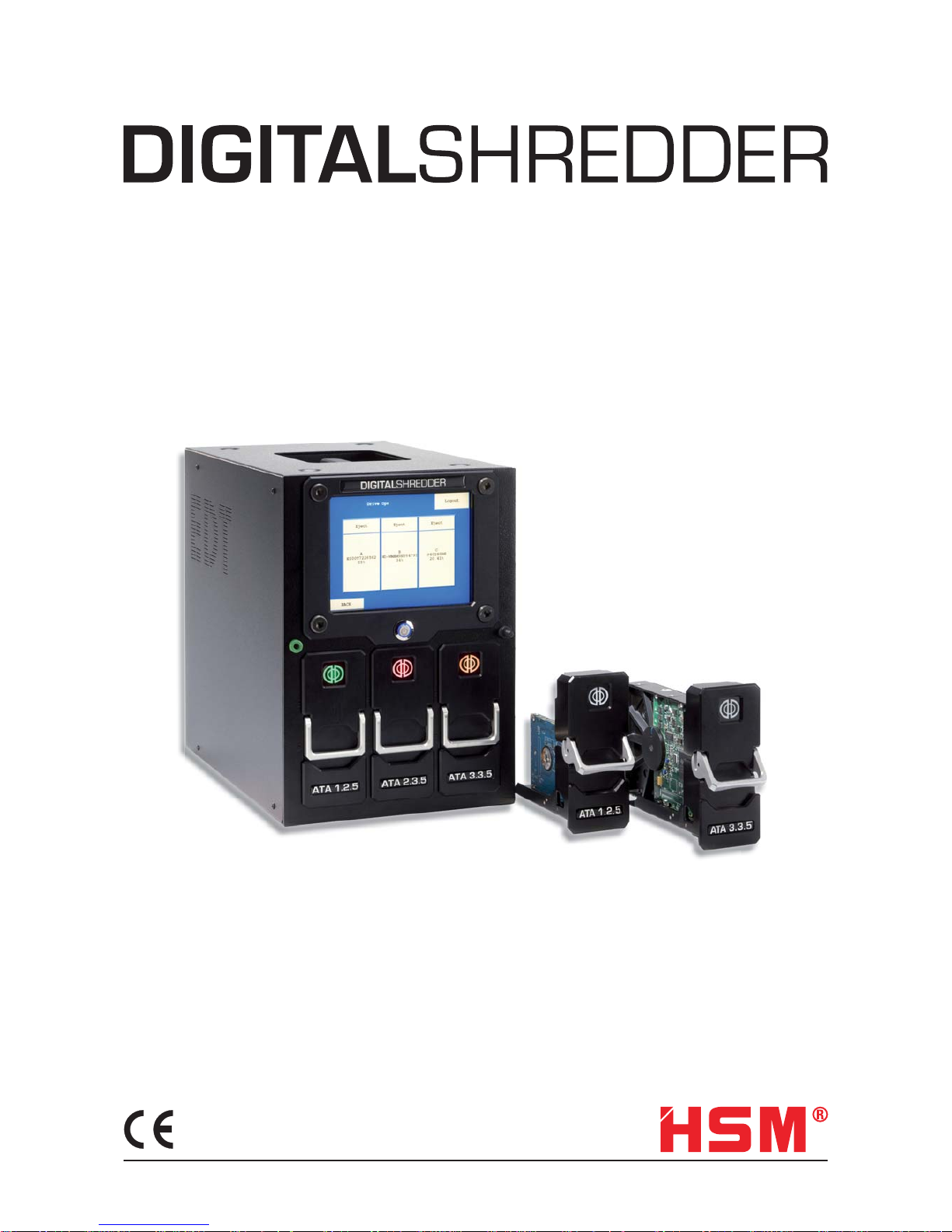
DIGITAL
SHREDDER
2
HSM GmbH + Co. KG
Bahnhofstrasse 115
88682 Salem
Tel. +49 (0) 75 53 / 822-0
Fax +49 (0) 75 53 / 822-160
info@hsm.eu
www.hsm.eu
www.digital-shredder.de
Page 3

0803
User Manual Digital Shredder
DIGITAL
SHREDDER
3
Table of Contents
Limited Warranty . . . . . . . . . . . . . . . . . . . . . . . . . . . . . . . . . . . . . . . . . . . 5
Lithium Battery Caution. . . . . . . . . . . . . . . . . . . . . . . . . . . . . . . . . . . . . . . . 5
Introduction to the Digital Shredder methodology . . . . . . . . . . . . . . . . . . . . . . . . 5
When Should I Use the Digital Shredder? . . . . . . . . . . . . . . . . . . . . . . . . . . . . . 6
Introduction to the Digital Shredder . . . . . . . . . . . . . . . . . . . . . . . . . . . . . . . . 7
Getting to Know the Digital Shredder . . . . . . . . . . . . . . . . . . . . . . . . . . . . . . . . 7
Setting up Your Digital Shredder . . . . . . . . . . . . . . . . . . . . . . . . . . . . . . . . . . 8
Entering Data into your Digital Shredder . . . . . . . . . . . . . . . . . . . . . . . . . . . . . . 8
Login Screen . . . . . . . . . . . . . . . . . . . . . . . . . . . . . . . . . . . . . . . . . . . . . . 9
System Confi g Screen . . . . . . . . . . . . . . . . . . . . . . . . . . . . . . . . . . . . . . . . 9
Setting Up Date and Time . . . . . . . . . . . . . . . . . . . . . . . . . . . . . . . . . . . . . . 9
Editing the User Screen . . . . . . . . . . . . . . . . . . . . . . . . . . . . . . . . . . . . . . . 10
Permission Levels . . . . . . . . . . . . . . . . . . . . . . . . . . . . . . . . . . . . . . . . . . . 11
Default Ops Screen . . . . . . . . . . . . . . . . . . . . . . . . . . . . . . . . . . . . . . . . . . 11
Inserting a Drive . . . . . . . . . . . . . . . . . . . . . . . . . . . . . . . . . . . . . . . . . . . . 14
Overview of the Secure Erase Process . . . . . . . . . . . . . . . . . . . . . . . . . . . . . . 15
Overriding Defaults and Setting Other Options . . . . . . . . . . . . . . . . . . . . . . . . . . 16
Processing a Drive . . . . . . . . . . . . . . . . . . . . . . . . . . . . . . . . . . . . . . . . . . 16
Removing a Drive . . . . . . . . . . . . . . . . . . . . . . . . . . . . . . . . . . . . . . . . . . . 17
History Screen . . . . . . . . . . . . . . . . . . . . . . . . . . . . . . . . . . . . . . . . . . . . . 17
History Search Screen . . . . . . . . . . . . . . . . . . . . . . . . . . . . . . . . . . . . . . . . 18
Search Fields . . . . . . . . . . . . . . . . . . . . . . . . . . . . . . . . . . . . . . . . . . . . . 18
Exporting History Data . . . . . . . . . . . . . . . . . . . . . . . . . . . . . . . . . . . . . . . . 19
Other activities . . . . . . . . . . . . . . . . . . . . . . . . . . . . . . . . . . . . . . . . . . . . 20
urning the Digital Shredder Off . . . . . . . . . . . . . . . . . . . . . . . . . . . . . . . . . . . 20
Testing the Printer . . . . . . . . . . . . . . . . . . . . . . . . . . . . . . . . . . . . . . . . . . . 20
Printer Supplies . . . . . . . . . . . . . . . . . . . . . . . . . . . . . . . . . . . . . . . . . . . . 21
Imaging a Drive . . . . . . . . . . . . . . . . . . . . . . . . . . . . . . . . . . . . . . . . . . . . 21
Reprinting a Certifi cation Label . . . . . . . . . . . . . . . . . . . . . . . . . . . . . . . . . . . 21
Backing Up and Restoring your Digital Shredder Software . . . . . . . . . . . . . . . . . . . 22
Upgrading your Digital Shredder Software . . . . . . . . . . . . . . . . . . . . . . . . . . . . 22
Recalibrating the Touchscreen of your Digital Shredder . . . . . . . . . . . . . . . . . . . . . 24
Accessories For Your Digital Shredder . . . . . . . . . . . . . . . . . . . . . . . . . . . . . . . 24
Where To Get Help. . . . . . . . . . . . . . . . . . . . . . . . . . . . . . . . . . . . . . . . . . . 24
Specifi cations . . . . . . . . . . . . . . . . . . . . . . . . . . . . . . . . . . . . . . . . . . . . . 24
Declaration of Conformity . . . . . . . . . . . . . . . . . . . . . . . . . . . . . . . . . . . . . . 25
Page 4

0803
User Manual Digital Shredder
DIGITAL
SHREDDER
4
Table of Figures (Screens)
Figure 1: Login Screen. . . . . . . . . . . . . . . . . . . . . . . . . . . . . . . . . . . . . . . . . 9
Figure 2: System Confi g Screen . . . . . . . . . . . . . . . . . . . . . . . . . . . . . . . . . . . 9
Figure 3: Edit User Screen . . . . . . . . . . . . . . . . . . . . . . . . . . . . . . . . . . . . . . 9
Figure 4: Date/Time Setup Screen . . . . . . . . . . . . . . . . . . . . . . . . . . . . . . . . . . 10
Figure 6: User Maintenance Screen. . . . . . . . . . . . . . . . . . . . . . . . . . . . . . . . . 11
Figure 7: Add User Screen . . . . . . . . . . . . . . . . . . . . . . . . . . . . . . . . . . . . . . 11
Figure 8: Default Screen . . . . . . . . . . . . . . . . . . . . . . . . . . . . . . . . . . . . . . . 11
Figure 9: Defaults Screen – Overwrite Options) . . . . . . . . . . . . . . . . . . . . . . . . . . 12
Figure 10: Defaults Screen – Single Pass Overwrite Options) . . . . . . . . . . . . . . . . . . 12
Figure 11. Drive Operation System. . . . . . . . . . . . . . . . . . . . . . . . . . . . . . . . . . 13
Figure12. Drive Operations Screen . . . . . . . . . . . . . . . . . . . . . . . . . . . . . . . . . 15
Figure13. Drive Operations Screen . . . . . . . . . . . . . . . . . . . . . . . . . . . . . . . . . 15
Figure 14. Overrides Screen . . . . . . . . . . . . . . . . . . . . . . . . . . . . . . . . . . . . . 15
Figure 15. Drive Operations Screen . . . . . . . . . . . . . . . . . . . . . . . . . . . . . . . . . 16
Figure 16. Drive Ops Screen . . . . . . . . . . . . . . . . . . . . . . . . . . . . . . . . . . . . . 17
Figure 17. Drive Operations Screen . . . . . . . . . . . . . . . . . . . . . . . . . . . . . . . . . 17
Figure 18. History Search Screen . . . . . . . . . . . . . . . . . . . . . . . . . . . . . . . . . . 18
Figure 19. History Search Date Screen . . . . . . . . . . . . . . . . . . . . . . . . . . . . . . . 18
Figure 20. Drive Serial Number Entry Screen . . . . . . . . . . . . . . . . . . . . . . . . . . . 18
Figure 21. User Identity Entry Screen . . . . . . . . . . . . . . . . . . . . . . . . . . . . . . . . 19
Figure 22. User Identity Entry Screen . . . . . . . . . . . . . . . . . . . . . . . . . . . . . . . . 19
Figure 23. History Data Export Screen . . . . . . . . . . . . . . . . . . . . . . . . . . . . . . . 19
Figure 24. History Data Export Screen . . . . . . . . . . . . . . . . . . . . . . . . . . . . . . . 19
Figure 25. Printer Setup Screen . . . . . . . . . . . . . . . . . . . . . . . . . . . . . . . . . . . 20
Figure 26. Printer Setup Screen . . . . . . . . . . . . . . . . . . . . . . . . . . . . . . . . . . . 20
Figure 27. Printer Setup Screen . . . . . . . . . . . . . . . . . . . . . . . . . . . . . . . . . . . 20
Figure 28. Software Backup Screen. . . . . . . . . . . . . . . . . . . . . . . . . . . . . . . . . 22
Figure 29. Software Update Screen . . . . . . . . . . . . . . . . . . . . . . . . . . . . . . . . . 22
Figure 30. Software Update Screen . . . . . . . . . . . . . . . . . . . . . . . . . . . . . . . . . 23
Figure 31. Software Backup Screen. . . . . . . . . . . . . . . . . . . . . . . . . . . . . . . . . 23
Page 5
User Manual Digital Shredder
DIGITAL
SHREDDER
5
0803
Limited Warranty
The warranty is valid for 12 months from the date of purchase and is limited to the free replacement of the whole device. The
statutory limitation period begins when the device is handed over to the shipping agency. This warranty excludes wear, damage due to improper handling, natural depreciation and actions taken by third parties.
Lithium Battery Caution
WARNING:
Caution:
There is a danger of explosion if battery is installed incorrectly. Observe the correct polarity when changing the lithium battery. Replace only with the same or equivalent type recommended by the manufacturer.
Dispose of used batteries according to the manufacturer’s instructions and local disposal requirements.
INTRODUCTION TO THE DIGTAL SHREDDER METHODOLOGY
Thank you for purchasing the Digital Shredder. This appliance will allow your organization to properly decommission hard
drives for reuse, recycling or removal.
The Digital Shredder destroys data using one of two methods. The fi rst and most powerful method is Secure Erase. Secure
Erase is performed by utilizing executing fi rmware level command contained in most modern ATA/IDE/EIDE/Ultra ATA and
SATA and PATA drives. In the event that Secure Erase is not available for your particular model of drive, the Digital Shredder
will default to using a compliant overwrite algorithm.
The Digital Shredder has many advantages over other data excising approaches:
Dedicated platform means no workstation downtime, no software installation, no software licensing and no boot fl oppies.
Unlike rack-mounted, or cumbersome test bench equipment, the Digital Shredder is self-contained and portable allowing for
fi eld tech support.
Your drive can be quickly erased, then partitioned and reformatted for immediate reuse.
With Secure Erase, the erasure process is completed in a fraction of the time of traditional overwriting.
Up to three drives can be processed simultaneously without any degradation of speed and performance using Secure Erase.
Erasure Certifi cation Labels and a detailed internal Event Log provide a defendable audit trail.
Page 6

User Manual Digital Shredder
DIGITAL
SHREDDER
6
0803
When Should I Use the Digital Shredder?
There are many occasions when drives should be decommissioned, some of which may be new to you.
The need for proper equipment disposal is an obvious occasion for decommissioning a hard drive, but there are several times
that are critical to practicing thorough end of life digital data methodology:
Preparation of equipment for charitable contribution.*
Preparation of equipment for warranty repair.*
Preparation of equipment for lease return, sale, recycling center or mechanical destruction.*
Preparation of equipment for reallocation (moving a PC from one site to another).*
Anytime there is any risk of your Organization’s data being released to the public, or even to other people within the Organization that may not have proper authorization, the Digital Shredder should be used to ensure that no residual data is left
behind by eradicating data beyond forensic reconstruction methods.
You can also use the Digital Shredder to prepare a drive for reuse by scripting the Digital Shredder to partition and reformat
the drive. The Digital Shredder also provides the user the ability to copy a binary image of one drive to another.
Page 7

User Manual Digital Shredder
DIGITAL
SHREDDER
7
0803
INTRODUCTION TO THE DIGITAL SHREDDER
Getting to Know the Digital Shredder
The Digital Shredder has been designed for ease of use and portability. 1.
Touch screen interface (no external keyboard or mouse are needed). 2.
Power button turns the unit ON and OFF. 3.
ESD ground strap connector. 4.
Stylus and stylus holder for entering data on the touch screen. 5.
Personality blocks, our proprietary cable-free connection technology, hold the subject drive in place during opera-6.
tion.
LED Indicator Lights in each drive bay show the status of the drive:7.
OFF: Bay is empty and available
Green: Drive is inserted and awaiting command
Green (blinking): Drive has successfully completed last process
Red: Drive is erasing
Red (blinking): A processing error has been encountered
Orange: Drive is processing partition, format or copy command
Drive Bays (3) - Up to three drives can be processed simultaneously. Drives can be of mixed interface and format. 8.
Drive bays are hot swappable.
Stylus – For use on touch screen; you may also use your fi nger. Never use anything sharp which may damage the 9.
screen such as a pen or pencil.
Carrying Handle - Integrated carrying handle on the top of the Digital Shredder allows the device to be transported 10.
in the fi eld.
Power Connector - Units accepts standard PC power cord.11.
USB Port (1) - Used to connect label printer; connect USB drive for software update or internal log export. 12.
Laminate Label Printer - Used to create certifi cation labels that can be applied directly to a processed drive.13.
Page 8
User Manual Digital Shredder
DIGITAL
SHREDDER
8
0803
Setting up Your Digital Shredder
Carefully remove the Shredder from packaging. Plug the power cord into the Digital Shredder and then into wall power. Insert
included printer battery according to included printer set-up instructions. Connect the supplied printer to the unit via the
supplied USB cable and plug the printer into wall power. The printer may be run off internal battery power when available.
Be sure to load the label tape material into the printer to prepare it for fi rst time use. Please refer to the printer manual for
instructions on loading the printer.
WARNING:
Be sure your Digital Shredder is powered ON before inserting drives for processing. Unpredictable behavior may result if this procedure is not followed.
NOTE:
Depressing the Power button while the Digital Shredder is processing a drive will NOT result in a shutdown of the unit. The
Digital Shredder cannot be powered down while a drive is being processed. Loss of power during any drive process may
leave the drive in an unusable state. Never unplug the unit while it is processing a drive. Also, it is recommended that the
Digital Shredder be connected to a UPS to avoid unintended loss of power.
Press the power button. As the machine powers up, the Digital Shredder logo will appear. When the boot sequence is complete, you will be presented with the login screen.
Entering Data into your Digital Shredder
The included stylus should be used to enter data into the Digital Shredder. It is allowable to press the screen with your fi nger
but using the stylus is generally faster and more accurate.
Never use a pen, pencil or other object as a substitute for the stylus. Such objects will damage the screen.
Page 9

User Manual Digital Shredder
DIGITAL
SHREDDER
9
0803
This screen is used to access all other Shredder functions.
Users: Add / Edit and Delete User Accounts
Printer: Verify printer operation by printing a
test label
Update: Process a software update
History: View / Print / Export audit records
Default Ops: Set default drive processing options
„Restore“: Restores the previous software
version
Logout: The user logs off and exits the appli-
cation
Back: Return to Previous Screen
Set Date/Time Set System Date and Time
Operations: Proceed to Drive Bay Status Screen
The fi rst thing you should do is change the password of
the Admin1 account and setup other User Accounts for
operators. To do this, select the “Users” option.
Setting Up Date and Time
Before starting to process drives, it is important to set the
date and time on your Digital Shredder so that the event
log records will have the correct date/time stamp.
To do this select the Set Date / Time option from the
System Confi g screen (see Figure 3).
Figure 3. Edit User Screen
Login Screen
Enter your username and password into the Login Screen
(see Figure 1). When you fi rst receive the unit it is set-up
with a default username and password. It is recommended
that you change the password for this user upon fi rst use.
The default username is ‘admin1’, and the default password is ‘shredder’.
Enter “admin1” in the User Name fi eld and select ENTER.
Enter “shredder” in the Password fi eld and select LOGIN.
Figure 1. Login Screen
System Confi g Screen
Once you have successfully logged in you will be presented with the System Confi g screen (see Figure 2). This
is the system’s Home Screen.
Figure 2. System Confi g Screen
Page 10

User Manual Digital Shredder
DIGITAL
SHREDDER
10
0803
Use the keyboard to enter the required fi elds as described
below:
0-9 Number keys
Enter Move to next fi eld
Today Fills in fi elds with today’s date as
maintained by the Digital Shredder
Clear Clear existing fi eld
Bksp Delete last character entered
Back Return to previous screen
Save Save values and return to previous screen
Year 4 digit year Month 2 digit month
Day 1 or 2 digit entry representing day of the
month
Hour 2 digit hour (military time, 15 = 3PM)
Minute 1 or 2 digit entry (0-59)
Second 1 or 2 digit entry (0-59)
If any of the fi elds fail to meet editing requirements an
error screen will be displayed highlighting the incorrect
value (see Figure 4).
Figure 4. Date / Time Setup Screen
Editing the User Screen
From the Edit Users screen you can add, edit, or remove
users (see Figure 5). To edit or remove an account, simply
touch the account to highlight it, then touch the action
button. To change the administrator account password,
select the administrator by touching it, then select the
EDIT option.
Figure 5. Edit User Screen
Touching the EDIT button on the User Maintenance Screen
takes you to the User Edit screen (see Figure 6). Here you
can change the users password or permissions level.
Figure 6. User Maintenance Screen
Page 11

User Manual Digital Shredder
DIGITAL
SHREDDER
11
0803
Default Ops Screen
While you are logged in as Administrator, it is helpful to
setup the default processes that will be performed each
time a drive is inserted and processed. This will save
considerable time while processing multiple drives.
To do this from the Home Screen select the Default Ops
option to access the Defaults screen (see Figure 8).
Figure 8. Default Screen
Now just touch the items that you like to use as defaults,
as follows:
Use Secure Erase if Possible
It is recommended that you always leave this as the default setting, which is ON. This instructs your unit to check
every drive to see if it can be Secure Erased.
Permission Levels
There are two permission levels, administrator and
operator. Administrators have full unit control including
the ability to export data, set process defaults and create
other users. Generally, there should only be a few administrators.
Figure 7. Add User Screen
Simply enter the user name and password then select the
appropriate permissions level and select “OK”. To abort
adding a user, select the “BACK” option
NOTE:
User names and passwords must be at least 6 characters
in length.
Page 12

User Manual Digital Shredder
DIGITAL
SHREDDER
12
0803
Use Default Overwrite Method
If this is ON, and the drive cannot be secure erased, then
the selected overwrite method will be used as the default
erasure method. If for some reason you have confi gured
your unit to not look for secure erase compatibility, then
this will be the default erasure method for every drive.
Keep in mind that this is only a default setting and can be
modifi ed at run time.
Currently, the Digital Shredder supports triple overwrite
and a single-pass overwrite (see Figure 9). For single-pass
overwrite, three additional options are available: Random
pattern, all bits zero and all bits one (see Figure 10).
Figure 9: Defaults Screen – Overwrite Options)
Figure 10: Defaults Screen – Single Pass Overwrite Options)
Page 13

User Manual Digital Shredder
DIGITAL
SHREDDER
13
0803
Operations Screen
The Operations Screen shows you the current status of all
three bays. When the unit has no drives inserted, the bay
LED’s will be OFF and the Operations Screen will show
that each bay is EMPTY (see Figure 11).
Figure 11. Drive Operation System
Create Default Partition
If this option is selected then after erasure is completed
the drive will be repartitioned. Partitioning assumes that
the entire drive is a single partition. If you desire multiple
partitions then you will need to place the drive into a PC to
perform the partitioning. If you select the partition option,
then you may also (optionally) choose to have the partition
formatted by selecting the Format Disk option described
below.
Format Disk
This will format the partition with the selected fi le system.
The Digital Shredder currently supports FAT16, FAT32,
NTFS, EXT1 and EXT2.
Disk Image
Assuming you have chosen to partition and format the
disk, you can also confi gure the Digital Shredder to copy
the contents of an ‘image’ drive on to the drive being processed. See the section entitled Disk Imaging for details on
this feature.
Print Certifi cate
Turning this option ON will provide a printed certifi cate
upon completion of the erasure process. If this option is
OFF, the label will not be printed automatically, however,
the information is stored in the Digital Shredder history.
The label can be reprinted at a later time.
The history contains the following information:
Hard drive serial number –
Operator username –
Type of erasure method used –
Date and time of the beginning and end of the –
operations
Now that you have successfully created your users and
have set your default options, you are ready to begin erasing drives. Information on the other System Screens can
be found at the end of this manual.
Page 14

User Manual Digital Shredder
DIGITAL
SHREDDER
14
0803
Inserting a Drive
Warning:
Be sure your Digital Shredder is powered ON before inserting drives for processing. Unpredictable behavior may result if this
procedure is not followed.
Drives are attached to Personality Blocks which are in turn inserted into Drive Bays. Your Digital Shredder shipment includes
three Personality Blocks. Personality Blocks are NOT universal in application with hard drives. Due to a lack of manufacturing standards concerning hard drives there are variations in the backplane of different drives. Each Personality Block has an
indicator on the front of it, describing the family of drives it serves. For example, the block ATA 1.3.5 is the fi rst ATA block and
is designed to fi t 3.5” drives from certain manufacturers who have created drives with that particular backplane. The ATA
1.2.5 block is the fi rst ATA block for 2.5” drives and so on.
Hardware Compatibility List:
ATA / IDE - 3,5“
Manufacturer Support Personality Block
Western Digital Yes ATA 2.3.5
Maxtor Yes ATA 3.3.5/ ATA 1.3.5
Seagate Yes ATA 1.3.5
Hitachi Yes ATA 1.3.5
IBM Yes ATA 1.3.5
Quantum Yes ATA 1.3.5
Fujitsu Yes ATA 1.3.5
ATA / IDE - 2,5“
Manufacturer Support Personality Block
AII Yes ATA 1.2.5
SATA - 3,5“ and 2,5“
Manufacturer Support Personality Block
AII Yes SATA
Check the status of the Personality Block before removing it. If the LED is OFF the block is safe to remove. If the light is
GREEN or blinking GREEN the bay is safe to open but may still be locked in which case you should select the “EJECT” option
on the Bay Screen to unlock the bay (see Figure 10).
To remove the Personality Block from the Drive Bay simply raise the lever on the face of the Personality Block and gently pull
it toward you. Remove the block completely from the bay. Now taking your drive in one hand and the block in the other, gently
align the two devices. If the alignment is correct, gently ease the drive on to the Personality Block connector. If it appears
that the alignment is not correct, do NOT force the connection as it is likely that the drive you are trying to erase requires a
different Personality Block.
Page 15

User Manual Digital Shredder
DIGITAL
SHREDDER
15
0803
Once your drive is connected to the block, align the bottom
rail of the block to the channel of the bay and slide the
drive in. Press down on the lever to engage the block with
the power connector located at the inside top of the bay.
You will know that the block is engaged correctly when
the lever is fully depressed and the bay indicator light is
lit.
Upon successful insertion the Digital Shredder will
automatically lock down the selected bay, recognize the
drive and present its information on the Operations Screen
within a few seconds (see Figure 12).
Figure12. Drive Operations Screen
Overview of the Secure Erase Process
When you insert a drive into the Digital Shredder you will
be presented with a screen showing you a visual representation of all three bays (see Figure 13).
Figure13. Drive Operations Screen
Bays that have drives inserted will display the manufacturer serial number of the drive. Empty bays are indicated by
the word ‘Empty’. Select a bay that has a drive inserted by
touching that specifi c bay on the screen. This will take you
to the Drive Confi g screen, listing the default actions to be
taken. These defaults are established by the Administrator
but may be overridden by any user. To set these options go
to the Default Ops screen (see Figure 14).
Figure 14. Overrides Screen
Page 16

User Manual Digital Shredder
DIGITAL
SHREDDER
16
0803
Overriding Defaults and Setting Other
Options
Type of Erasure
Select “Triple Overwrite” or “Secure Erase”; default is
“Secure Erase”.
Partition the drive upon completion
Select YES or NO; default is NO. If YES, the drive will be
partitioned as a single partition sized to the drive capacity.
Reformat the drive
Select YES or NO; default is NO. To make this option
active, “Partition the drive upon completion” must be set
to YES. If YES, you must select the fi le allocation system
to be used. The resulting drive will be formatted but no
system fi les will be applied.
Image the drive
Select YES or NO; default is NO. You must have Partition
set to YES, and Format set to YES to make this option
active. If imaging has been turned on after the drive is
erased, partitioned and formatted, the contents of the
drive located in drive bay C will be copied to the target
drive. This requires that the target drive has the same
or larger capacity as the image drive and is inserted in
either Bay A or B. Print Certifi cation Label – Select YES
or NO; default is YES. At the end of the erasure process a
certifi cation label will be printed. This label contains the
following information:
Hard Drive Serial Number *
Operator Username*
Type of Erasure Method used *
Date and Time of the Beginning and End of the *
Operations
Bar Code of Hard Drive Serial Number*
Processing a Drive
CAUTION:
ATTEMPTING TO REMOVE A PERSONALITY BLOCK
WHILE A DRIVE IS IN PROCESS CAN RESULT IN
DAMAGE TO THE DIGITAL SHREDDER.
Now that your option selections are made, begin processing the drive by selecting the “RUN” option (see Figure
15).
Figure 15. Drive Operations Screen
The Status Field will indicate the drive’s progress. Remember that most erasure activities are lengthy processes,
taking anywhere from an hour to several hours depending
on the size of the drive and the erasure method selected.
During processing, the Personality Blocks are locked down
in their respective the bays by solenoid locks that are engaged upon block insertion. This precaution ensures that
the decommissioning process is not interrupted and allows
the operator to safely leave the machine in a running
state. When the process has completed, the screen will
revert to the Drive Ops screen, and the EJECT button can
be used to unlock the drive bay and remove the drive.
During the erasure process the indicator LED will turn RED.
During the erasure process, you may continue to process
other drives in the other available bays.
Page 17

User Manual Digital Shredder
DIGITAL
SHREDDER
17
0803
Removing a Drive
To remove a drive, you must fi rst select the “Eject” option
located at the top of each bay status area on the Operations Screen (see Figure 16).
Figure 16. Drive Ops Screen
Selecting the “Eject” option will unlock the bay and allow
for device removal. Drives may be removed at any time,
however, if you select “Eject” while the drive is being
processed, it may take several seconds for the Digital
Shredder to suspend operations and release the drive. In
this event, no certifi cate will be printed for the drive and
the audit log will contain entries showing that the process
was aborted prematurely.
History Screen
The History Screen is used to access the audit log of
the Digital Shredder. Numerous activities are logged by
the Digital Shredder including login, logout, and drive
operation status messages. This log can be reviewed in
chronological order or searched using several parameters
(see Figure 17).
Figure 17. Drive Operations Screen
Back Return to System Confi g Screen.
Purge Erase the current audit log, this
function is limited to administrator
level users only. You should always
conduct an Export before using this
function.
Search Allows user to review selected re-
cords based on User-Entered criteria.
Export Copy entire contents of audit log to
external USB drive (see explanation
in ‘Other Activities’ section).
Page 18

User Manual Digital Shredder
DIGITAL
SHREDDER
18
0803
History Search Screen
The History Search screen can be used to view a subset
of the event log by fi ltering the log based on a date range,
a hard drive serial number or a specifi c user (see Figure
18). These results are displayed on screen only and cannot
be exported. Only a system administrator may perform an
export and only the entire log can be exported.
Figure 18. History Search Screen
Back Return to History Screen.
Clear Reset all search fi elds to blank and OFF
OK Run Search
Search Fields
All of the search fi elds can be enabled or disabled. Ena-
bled fi elds are used in combination. For example, specify-
ing a date range and a user ID, will give you all records for
that user, during that date range, inclusive.
Date – Enable/Disable
Use the edit button to specify a range of dates as a fi lter.
Entering only a start date will result in all records greater
than the date, entering only an end date will result in all
records less than the date. Selecting the keyboard icon
next to the date fi eld will bring up the following entry
screen (see Figure 19).
Figure 19. History Search Date Screen
Serial Number – Enable/Disable
By selecting options on the edit button and keypad displayed on the screen, enter the serial number of the drive.
Partial strings are acceptable.
Figure 20. Drive Serial Number Entry Screen
User – Enable/Disable
Using the Edit button and keypad, enter the User ID.
Page 19

User Manual Digital Shredder
DIGITAL
SHREDDER
19
0803
Figure 21. User Identity Entry Screen
Type – Enable/Disable
Using the drop down list select the type of error to be
located or select ALL to include all records.
Figure 22. User Identity Entry Screen
Exporting History Data
Press „Export“ to bring up the Export History screen (see
Figure 21).
Figure 23. History Data Export Screen
You will be prompted to insert a USB drive into the USB
port in the back of the unit. Once you have done this and
drive is recognized, you will see the following screen.
Figure 24. History Data Export Screen
Now select the “EXPORT” option. The entire audit log will
be copied to the device in CSV format. The fi le name will
be based on the current date. (e.g. 20060904-224207-log.
csv). You may now load this fi le into Excel or another
program to create custom reports.
Page 20

User Manual Digital Shredder
DIGITAL
SHREDDER
20
0803
OTHER ACTIVITIES
Turning the Digital Shredder Off
Never unplug the Digital Shredder.
Always use the Power button to power down the Digital
Shredder. When the Digital Shredder is idle, depressing
the Power button will cycle the unit OFF. Depressing the
Power button while the Digital Shredder is processing a
drive will NOT result in a shutdown of the unit. The Digital
Shredder cannot be powered down while a drive is being
processed. Loss of power during any drive process may
leave the drive in an unusable state. It is recommended
that the Digital Shredder be connected to a UPS to avoid
unintended loss of power.
Testing the Printer
A facility has been provided for testing the printer operation before processing any drives. This test can be useful
to perform if the Digital Shredder has been relocated, or
the printer cartridge has been changed. From the System
Confi g screen, select the “Printer” option and the Printer
Setup screen will appear (see Figure 25).
Figure 25. Printer Setup Screen
Select the “Test Print” option to send a label format test to
the connected printer.
Figure 26. Printer Setup Screen
Select “OK” once you have confi rmed that the printer is
connected and power is on.
Figure 27. Printer Setup Screen
It may take up to 60 seconds to complete this test; please
be patient and do not repeat the test until this time has
elapsed or you will get multiple test labels.
Page 21

User Manual Digital Shredder
DIGITAL
SHREDDER
21
0803
Printer Supplies
The supplied Brother PT-18R printer uses standard ½” TZ tape cartridges which are available at most offi ce supply stores.
Imaging a Drive
An image created using the Digital Shredder is an exact binary copy of a source drive to a target drive. The image process
includes not only ALL fi les but partition information as well. To image a drive you need two drives, a source drive and a target
drive. The target drive must be at least the same size as the source drive in order to make a complete copy. The target drive
should be high level formatted (most drives are today). It does not matter if the target and source drives are the same manufacturer or model number. In fact they can even be different formats (3.5” v 2.5”).
The imaging process will overwrite any existing partitions on the target drive. This is a necessary part of creating an exact
image of the source drive. If the target drive is much larger than the source drive, this can result in a signifi cant amount of
‘unpartitioned’ space on the target drive.
Place the source drive in Bay C, as this is the default bay for source drives and cannot be changed. Whenever you are imaging drives the source drive must go in Bay C. Place the target drive in either Bay A or B.
You can image a drive as part of its erase process by including the option in the processes script along with your other selections. When the drive has been erased, partitioned and formatted, the contents of the drive in Bay C will be copied on to the
erased drive.
It is also possible to directly image a target drive by passing the erasure process. This is recommended as a time saving
measure to be used when the target drive is new or previously erased.
Simply place the source drive in Bay C as usual, and the target drive in Bay A or B, select the target drive from the Drive Ops
screen once it is recognized, then call up the Options screen. Turn off all activities except the Image option, exit the screen
and run the process.
The progress indicator will show you an estimate of how much longer until completion. When the process is complete,
remove the two drives.
Reprinting a Certifi cation Label
Go to the System Confi g and select the “History” option, go to the Search screen and enter in the search criteria for the drive
in question. Select the Run Complete record from the results screen by touching it, then select the “REPRINT” option. Note
that the REPRINT option is only available for drives that have successfully completed an erasure process.
Page 22

User Manual Digital Shredder
DIGITAL
SHREDDER
22
0803
Backing Up and Restoring your Digital Shredder Software
The Update Process automatically creates a backup of
the currently installed version before proceeding with the
update process. In the event the Update Process results
in an error, or for any other reason you need to restore
your Digital Shredder to the prior version of the software,
simply go to the Software Backup Screen. Once you have
confi rmed that the backup exists and select the “Restore”
option (see Figure 28).
Figure 28. Software Backup Screen
Figure 29. Software Update Screen
“Cannot update while backups exist.Would you like to
remove backups?“ Enter „OK“. To abort, select “CANCEL.”.
Upgrading your Digital Shredder Software
To begin the upgrade process you must fi rst download
the most recent version of the software from the HSM
Corporate website at
www.digital-shredder.de/downloads
Update Process:
Download the most recent version of the soft-1.
ware and save it to your computer.
Connect USB Drive to your computer.2.
USB DRIVE REQUIREMENTS:
In order to successfully complete the update process, the
USB drive MUST BE at least 256MB in size, MUST NOT
contain any existing data and MUST NOT be a „smart“
USB drive. „Smart“ USB drives are those that contain preinstalled software such as U3 and others.
Extract the update package to the folder called 3.
„HSMds-update“.
This folder should be located in the root directory of the USB Drive. If you have not updated
your software previously, you will need to create
this folder.
Insert the USB drive to the USB port on the back 4.
of the Digital Shredder. Be sure that all drive
bays are empty before inserting the USB drive.
After the Digital Shredder has installed the soft-5.
ware from the USB drive, the device will reboot
in order to complete the update process.
From the System Confi g Screen, select the “UPDATE” op-
tion to access the Software Update screen (see Figure 30).
Page 23

User Manual Digital Shredder
DIGITAL
SHREDDER
23
0803
Figure 30. Software Update Screen
Insert the USB drive into the USB port on the back of the
Digital Shredder. Upon insertion, the new version of the
software (as well as any older versions stored on the
drive) should be displayed. Highlight the version to be
installed and select the “UPDATE” option to begin the
update procedure. Note that the UPDATE option is only
enabled when a valid update version is present on the
USB drive.
If a prior Update operation has created a backup copy of
the prior software version or a user request was made to
create a backup copy, this backup must be removed so the
update can proceed. If you get the following error
“Cannot do update while backups exist. Would you like to
remove backups?” select “OK”. To abort, select “CANCEL.”
After removing backups, you will return to the Software
Update screen where you can resume the Update process.
Figure 31. Software Backup Screen
The upgrade process will result in a reboot of the Digital
Shredder to load the new application. Be sure that all
drive bays are empty before updating the Digital Shredder.
The update process automatically creates a backup of the
current version so that the prior version can be restored if
necessary. To restore a previous software version, select
the “Restore” option on the System Confi g Screen. Previ-
ous backups will be displayed if present on the USB drive,
from which you can highlight a specifi c backup version and
select “OK” to execute the software restoration.
When you have completed your backup or update procedure, select the “EJECT” option to remove the USB drive
safely.
Page 24

User Manual Digital Shredder
DIGITAL
SHREDDER
24
0803
Recalibrating the Touchscreen of your Digital Shredder
Your Digital Shredder screen was calibrated at the factory and should never require recalibration. However, in the unlikely
event that it does, the following procedure will allow a user to access the calibration routine.
Turn the Digital Shredder OFF *
Turn the Digital Shredder ON*
As soon as the full screen DOD logo appears touch the screen for at least 5 seconds, which will activate the calibration
routine. Following the on screen instructions, enter the fi ve points by touching the cross hairs.
After the fi fth point is entered the screen will recalibrate and the application will load
Accessories For Your Digital Shredder
There are several useful accessories for your Digital Shredder, including a hard shell travel case, and a variety of personality
blocks for different drive interfaces and form factors.
Where To Get Help
Please visit HSM’s website to review The Digital Shredder’s Frequently Asked Questions page at:
www.digital-shredder.de
If you have a specifi c technical question or need to report a problem with your shredder, please contact HSM’s Technical Sup-
port Team through
our forum at www.digital-shredder.de or1.
our contact form (e-mail) at www.digital-shredder.de2.
Specifi cations
Voltage: 230 V AC
Current: 2.5A RMS @ 230 V AC
Watts: 575 W
Frequency: 47 - 63 Hz
Temperature Range: Operating: 0 °C to 35 °C (32 °F to 95 °F)
Storage: -40 °C to 65 °C (-40 °F to 149 °F)
Relative Humidity: Operating: 10 % to 90 % (non-condensing)
Storage: 5 % to 95 % (non-condensing)
Altitude (maximum): Operating: -15,2 m to 3.048 m (-50 to 10.000 ft)
Storage: -15,2 m to 10.668 m (-50 to 35.000 ft)
Page 25

User Manual Digital Shredder
DIGITAL
SHREDDER
25
0803
Declaration of Conformity
Machinery directive 98 / 37 / EG
EMC directive 89 / 336 / EWG
Low voltage directive 73 / 23 / EWG
The manufacturer HSM GmbH + Co. KG, Bahnhofstrasse 115, D-88682 Salem declares herewith, that the Digital
Shredder correspond with the above mentioned EC Machine Directive including all relevant modifi cations.
Applied standards and technical specifi cations:
• EN 55022: 1994
• EN 55024: 1998
• EN 61000-3-2: 1995
• EN 61000-3-3: 2000
• UL 60950-1: 2006
Salem, 03.03.2008
Rolf Gasteier - Technical Director
 Loading...