

Page 1
User’s Manual
TM-810LM
All-In-One Mainboard
Version: 1.0
Warning: Never run the processor without the heatsink properly
and firmly installed. Permanent Damage Will result!
1
Page 2

User’s Manual
Copyright
Copyright © 2000 by this manufacturer. All rights reserved. No part of this
publication may be reproduced, transmitted, transcribed, stored in a retrieval system,
or translated into any language or computer language, in any form or by any means,
electronic, mechanical, magnetic, optical, manual or otherwise, without the prior
written consent of this manufacturer.
Disclaimer
This manufacturer makes no representations or warranties, either expressed or
implied, with respect to the contents hereof and specifically disclaims any
warranties, merchantability or fitness for any particular purpose. Any software
described in this manual is sold or licensed “as is”. Should the programs prove
defective following their purchase, the buyer (and not this manufacturer, its
distributor, or its dealor) assumes the entire cost of all necessary servicing, repair,
and any incidental or consequential damages resulting from any defect in the
software. Further these manufacturer reserves the right to revise this publication and
to make changes from time to time in the contents hereof without obligation to
notify any person of such revision or changes.
Trademark Acknowledgement
Intel and Pentium are registered trademarks of Intel Corporation. Award is a
registered trademark of Award Software Inc. Other brand and product names are
trademarks and/or registered trademarks of their respective holders.
Printed in Taiwan
2
Page 3

User’s Manual
Overview
The TM-810LM is a Pentium III Socket 370 based mainboard that utilizes
Intel i810E chipset on All-In-One platform. It supports Intel PPGA (Plastic Pin
Grid Array) Celeron up to 800 MHz and FC-PGA processor up to 966GHz.
This mainboard integrates a 3D AGP Graphics Accelerator, PCI 3D Sound
System, 10 BaseT/100 BaseTX Network interface and V.90 Fax/Modem
DAA Module. Additionally, there is a TV-Out and LCD Raiser slot onboard
for outputting system Video to TV and LCD panel. This Flex-ATX size
mainboard is also featured with PS/2 keyboard and mouse ports, a RJ-45
LAN port, two USB ports and a parallel port, a serial port and VGA port.
This all-in-one mainboard featured complete specifications to develop a
powerful multimedia PC or workstation.
3
Page 4

User’s Manual
CONTENT
Copyright...................................................................................2
Disclaimer..................................................................................2
Overview....................................................................................3
CONTENTS………………………………………………………….4
Introduction...............................................................................6
SPECIFICATIONS........................................................................6
Setup Guide...............................................................................9
LAYOUT DIAGRA………………………………………………….9
JUMPER SETTINGS……………………………………………...11
EscoCAM - An Integrated Module For Escorting PC …..……..12
BIOS Update Note………………………………………………...17
BIOS Set UP ………………………………………………………18
Standard CMOS Setup.......................................................19
Advanced Setup..................................................................20
Power Management............................................................22
PCI/PnP Setup....................................................................24
Load Optional Settings........................................................25
Load Best Performance Settings........................................25
Features Setup......................................................................26
CPU PnP Setup ....................................................................28
4
Page 5

User’s Manual
HardWare Monitor …………………………………………….29
Change or Remove The Password.....................................30
Exit………… 30
DRIVER & SOFTWARE ..........................................................31
Block Diagram ………………………………………………..…36
POST CODE…… .…………………….
…………………………..37
PROBLEM SHEET…..………………….
…………………………..44
MEMO………………………….…….………………………..…45
5
Page 6

User’s Manual
Introduction
Specifications
System Chipset Intel i810e chipset.
CPU Supports 66MHz Clock PPGA Celeron up to 800
MHz and and 100, 133 Clock FC-PGA up to 966
MHz.
Memory Supports 2 x DIMM of 66, 100 and 133 MHz
memory maximum up to 512MB.
VGA On Board
*3D AGP Graphics Accelerator optimized for
smooth 2D and 3D video.
*Shared memory architecture does not require
dedicated video memory.
*Supports hardware DVD Accelerator and Direct
DVD to TV playback.
*Supports high resolutions up to 1600x1200 16M
colors.
Sound On Board *16 bit Codec for full-duplex playback & recording
*Complies with PC98 audio specs.
*Direct Sound 3D & 4-channel speakers.
*Built-in 32 ohm earphone buffer & 3D surround
sound.
*Provides MPU-401 Game/MIDI port and legacy
Sound Blaster 16 supported.
*Downloadable Wave-Table Synthesizer supports
Direct Music.
*Stereo Mixer supports analog mixing from CD Audio and line In.
6
Page 7

User’s Manual
LAN On Board *Built-In 10BaseT-100BaseTX Ethernet LAN.
*LAN controller integrates Fast Ethernet MAC and
PHY compliant with IEEE802.3u 100Base-TX,
10 Base-T and ANSI x3.263 TP-PMD standards.
*Compliant with ACPI 1.0 and the network Device
Class Power Management 1.0
*High performance provided by 100Mpbs clock
generator and data recovery circuit for 100Mbps
receiver.
Fax/Modem DAA
Module attached
*56Kbps Fax/Modem DAA module
*Supports V.90, V.34, V.32bis, V.32, V.22bis, V.22
*Supports Auto Fallback and MNP5, V.42bis data
compression with 115, 200-compatible Virtual
UART.
*Requires 16MB RAM and Microsoft Windows
95/98/NT
I/O *1 x high speed 16550 compatible serial ports,
(2nd serial port available with extension bracket
is optional)
*1 x Parallel Port support SPP/EPP/ECP standard
mode.
*2 x onboard PCI IDE Ports, (32-bit data transfer)
and Ultra ATA 33/66 modes.
* LS-120/ ZIP FDD, IrDA/ ASK IR/ Consumer IR.
2 x USB ports.
*Support two 360/720KB/1.2/1.44/2.88MB floppy
disk devices.
*Two PS/2 port for keyboard and mouse.
Hardware Monitoring Monitoring for CPU & System temperature, fan
Speeds and mainboard voltages.
BIOS AMI (Flash and PnP).
7
Page 8

User’s Manual
Expansion slots 2x PCI Slots, 1 x slot for TV-Out and LCD Raiser.
Dimension 4-layer PCB, size (23mm x 19mm).
Bundled Software *Super VB : Provides anti-virus protection.
*Super Voice : For data, FAX and voice
communication.
*Gamut 2000: Provides professional audio
features.
*Media Ring Talk : Provides PC to PC, or PC to
phone internet communication.
*Corel WordPerfect Suite 8 : A office application
suite under Windows.
*3 DEEP : Provides for adjust color, contrast and
brightness of monitor.
Package Contents *The mainboard
*The Manual
*CD Driver
*ATA 66 & FDD cables
*Fax/Modem DAA Module
Optional Accessories *2nd Serial port extension bracket.
*TV-out Riser card.
8
Page 9
User’s Manual
Setup Guide
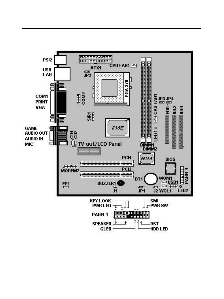
A.Layout Diagram
9
Page 10
User’s Manual
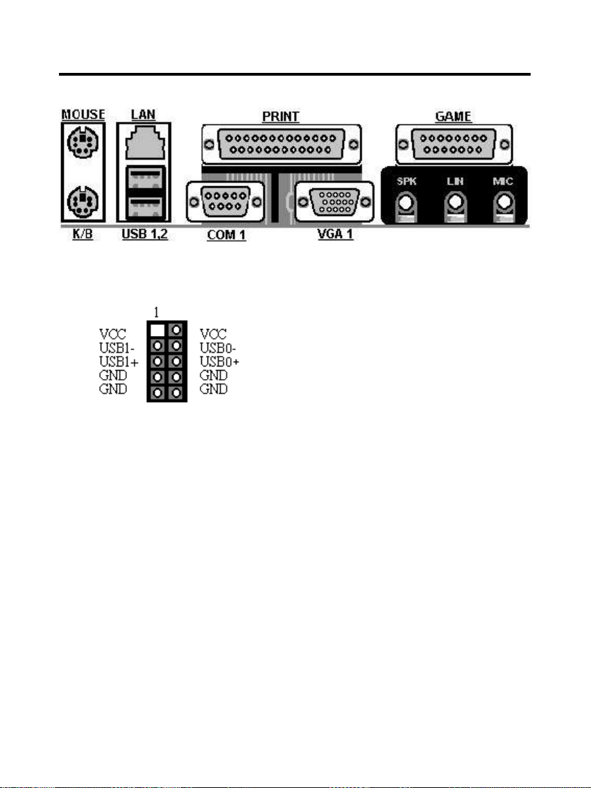
USB1 : USB Connector
SIR1 : Infrered Port (IrDA)
1 – VCC
2 – NC
3 – IRRx
4 – GND
5 - IRTx
10
Page 11
User’s Manual
B. Jumper Settings
When put a jumper cap on two pins to short, we name it ON. When remove
jumper cap from two pins or just put on one pin, we name it OFF.
JP1 : Clear CMOS Memory
Pin 1-2 On Normal Operation
Pin 2-3 On Clear CMOS Memory
JP2 : Keyboard Power On Set Up
When enable Keyboard Power On Set Up, you are able to Power On/Off via
hot keys setting. However, the power supply must provide minimum 750mA
on the +5VSB (+5V Standby) for working normally.
JP3 : Set CPU Clock to 100 MHz
No
matter what the CPU clock is 66 or 133 MHz, the CPU Clock is
forced to run 100 MHz once Pin 2-3 is On.
JP4 : Set CPU Clock to 133 MHz
No
matter what the CPU clock is 66 or 100 MHz, the CPU Clock is
forced to run 100 MHz once Pin 2-3 is On.
EscoCAM – An Integrated Module
Pin 1-2 On Enable Keyboard Power On
Pin 2-3 On Disable Keyboard Power On
Pin 1-2 On Normal Operation
Pin 2-3 On Setting Clock to 100 MHz
Pin 1-2 On Normal Operation
Pin 2-3 On Setting Clock to 133 MHz
11
Page 12
User’s Manual
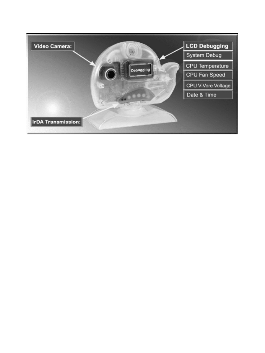
It’s so valuable that you don't have to pay thrice to buy three fashionable devices of
PC Camera, Debugging and IrDA ware now because we have integrated them into
our EscoCAM in the shape of a lovely whale to escort your system. The whale is the
king of the sea and the symbol of all-mighty power. With PC camera, Debug, CPU
heat monitor and IrDA device built into the EscoCAM, we offers you the unbeatable
solution to upgrade the value of your PC system.
1. PC Camera:
As video and audio email is gaining popularity, PC cameras are making inroads into
PC systems and it will increasingly become a standard PC peripheral. In view of this
strong market demand, we has timely launched its state-of-the-art PC cameras.
Besides, our PC Camera is allowed to adjust the Focus of Camera via Keyboard
or mouse instead of wheel. It’s a patent design in PC Camera. Hope you enjoy
this new technology.
2. External Debug :
When initializing system, LCD will check the peripherals of CPU, Chipset, DRAM,
BIOS, Keyboard, CMOS, VGA card, Devices, FDD, HDD and Cache…Once
peripherals were not been properly installed or defective, the LCD display will show
out the detective place. After system successfully booted up, Time & Date, CPU
Temperature, CPU V-Core Voltage, CPU Fan Speed will take turn to show out on the
LCD display.
Advantages of Debug Device For User:
In comply with fast development of IT and e-Commerce, the time of people
12
Page 13

User’s Manual
to stay together with PC is beyond what we can image. Eventually,
prolonged use of PC is unavoidable to cause high defect rate. Especially,
when warranty is over, user is not in a position to bargain the upraising repair
cost. The worse is that users are always overcharged when they have don’t
have any sense about defect status. However, once PC system is equipped
with basic debugging devices, user is able to easily understand how far the
hardware problem going; thereby drastically minimize the time and cost from
RMA.
3. Monitor CPU Temp. And FAN Working Status:
Audio, video and multi-tasking functions call for faster and faster CPUs to
improve system efficiency. However, faster CPUs will generate more heat
which must be dissipated in a timely manner. Therefore, a more efficient
fans to dissipate heat is as important as watch-out of fan working situation.
In this Internet era, people are using their computers for longer and longer
time which can easily cause overheat and damage to the CPU. Prolonged
use of the computer will increase CPU temperature. It is therefore necessary
to have a device to constantly monitor the CPU temperature, CPU fan speed
and V-Core voltage and timely remind user.
4. IrDA For Data Transmission :
As more and more computers, notebook, mobile phone and PDA are
installed with the IrDA device for wireless transmission, we add in this extra
value in the EscoCAM.
The Connection of EscoCAM
13
Page 14
User’s Manual
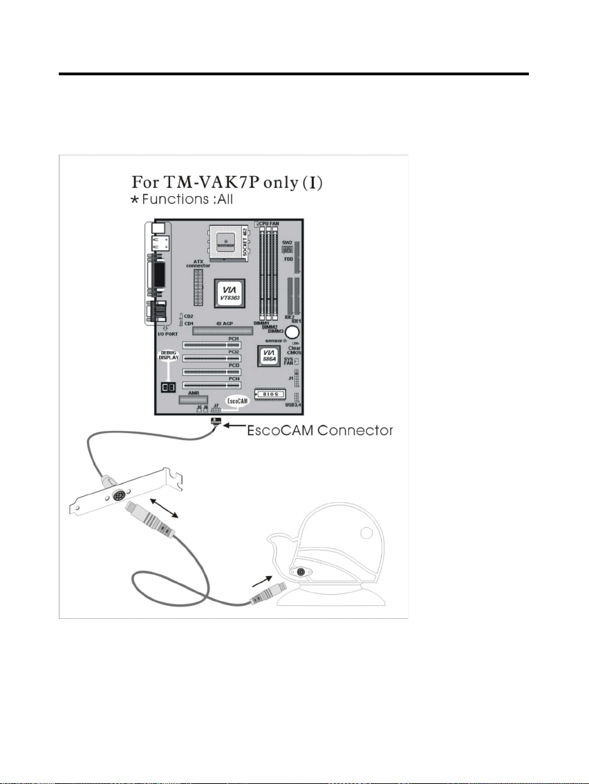
I. For TM-VAK7 Mainboard :
If you use TM-VAK7P, the most updated mainboard, it’s already built-in all the
circuit of EscoCAM so that user don’t need a extra daughter card to connect it.
The connection drawing as follows:
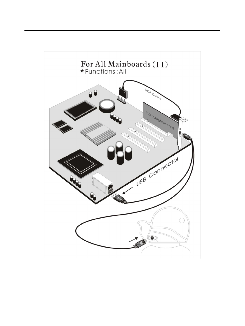
II. For All Others Mainboards:
If the mainboard you used is not TM-VAK7, you need A PCI daughter card to
14
Page 15
User’s Manual
be inserted and make connection as follows:
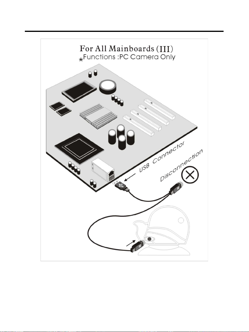
III. Or, if you just want use the function of PC Camera, the connection
drawing as follows:
15
Page 16
User’s Manual
BIOS Update Note
16
Page 17

User’s Manual
Do not update the BIOS if no abnormalities occur. However, if BIOS update
is needed, consult your dealer first. Prior to updating your BIOS, you
are recommended to save the original BIOS values.
1. Download the AMI BIOS Flash Utility file (AMIFL818.exe)
2. Download the BIOS file used by your mainboard(e.g., xxx.BIN)
3. Reboot your system (but do not run Himem.sys and Emm386.exe)
to execute the new BIOS program.
4. Execute these commands: AMIFL818 xxx.BIN
17
Page 18
BIOS Setup
BIOS Setup
This Flash ROM BIOS has a built-in Setup program that allows users to modify the
basic system configuration. This information is stored in battery-backed RAM so
that it retains the Setup information when the power is turned off.
Getting Help
The online description of the highlighted setup function is displayed at the bottom
of the screen.
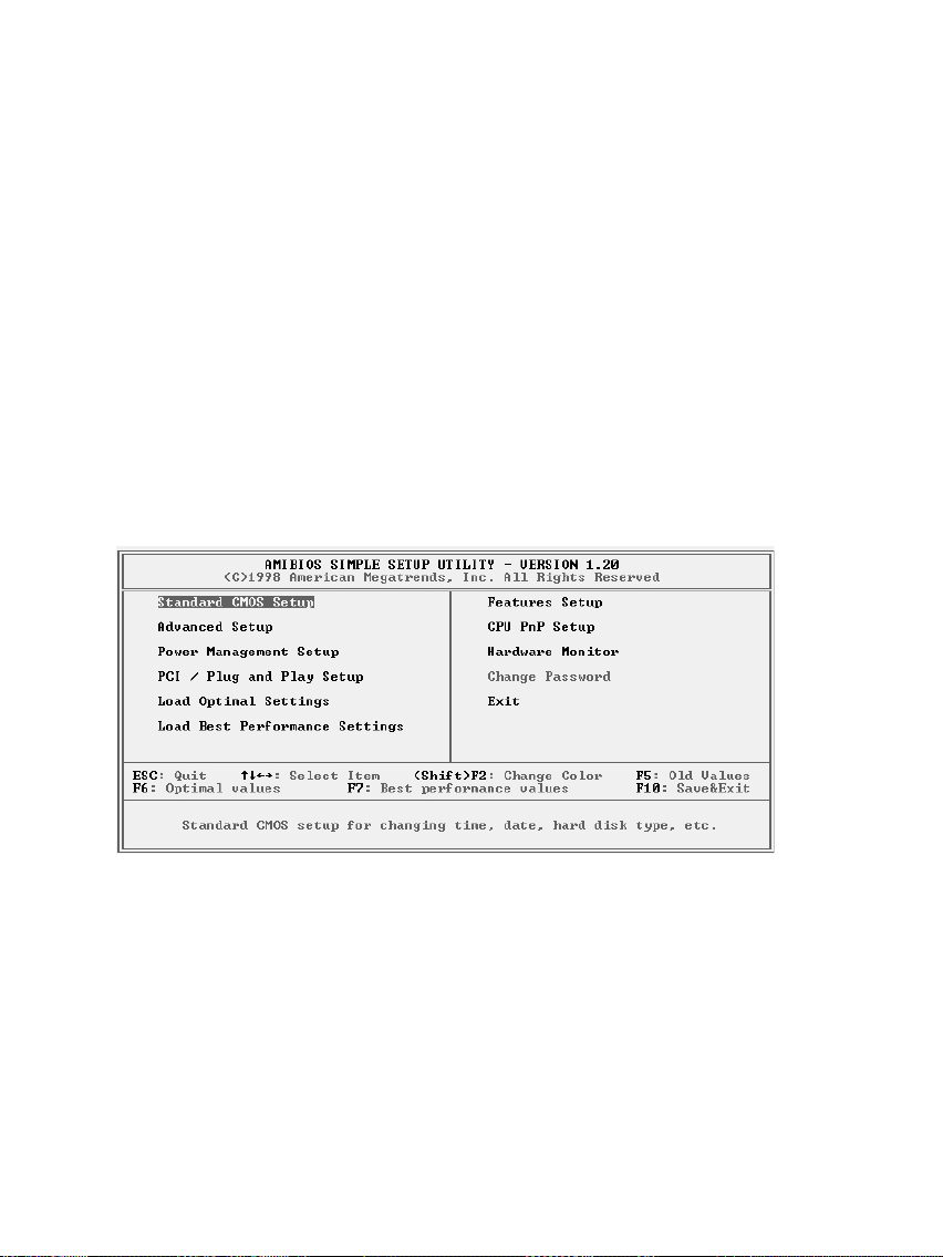
The Main Menu
Once you enter BIOS CMOS Setup Utility, the Main Menu will appear on the
Screen.. Use arrow keys to select the desired items, press <Enter> to select or
enter a submenu.
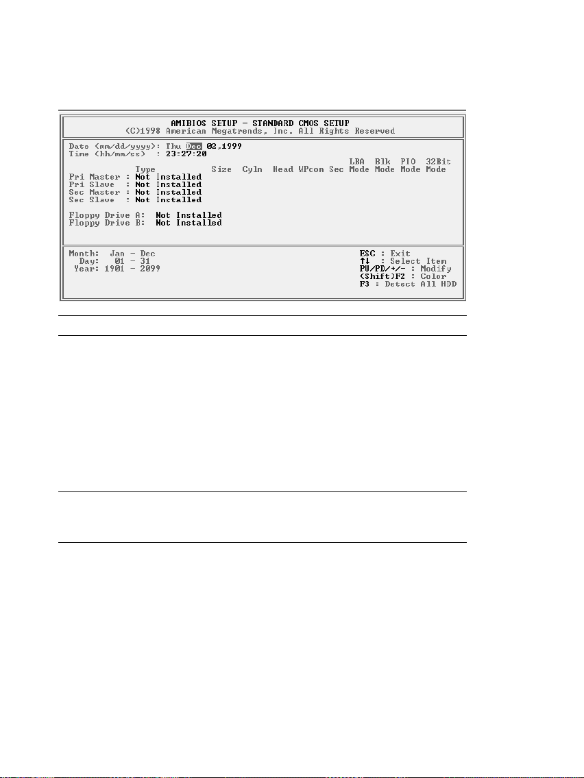
Standard CMOS Setup
The items in Standard CMOS Setup Menu are divided into several categories. Each
category includes no, one or more than one setup items. Use the arrow keys to
18
Page 19
BIOS Setup
highlight the item and then use the <PgUp> or <PgDn> keys to select the value you
want in each item.
Date & Time
Use these items to set the system date and time
Pri Master
Pri Slave
Sec Master
Sec Slave
Use these items to configure devices connected
to the Primary and Secondary IDE channels. To
configure an IDE hard disk drive, choose Auto. If
the Auto setting fails to find a hard disk drive, set
it to User, and then fill in the hard disk
characteristics (Size, Cyls, etc.) manually. If you
have a CD-ROM drive, select the setting
CDROM. If you have an ATAPI device with
removable media (e.g. a ZIP drive or an LS-120)
select Floptical.
Floppy Drive A
Floppy Drive B
Use these items to set the size and capacity of
the floppy diskette drive(s) installed in the
system.
19
Page 20
BIOS Setup
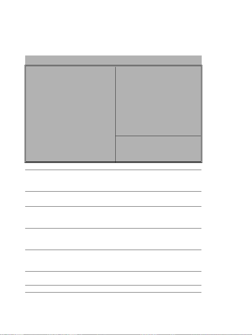
Advanced Setup
Use this page to set more advanced information about your system. Take some care
with this page. Making changes can affect the operation of your computer.
AMIBIOS SETUP – ADVANCED SETUP
©1998 American Megatrends, Inc. All Rights Reserved
Trend ChipAwayVirus Enabled
Boot From OnBoard LAN Disabled
1st Boot Device IDE-0
2nd Boot Device Fl oppy
Try Other Boot Devices Yes
S.M.A.R.T. for Hard Disks Disabled
BootUp Num-Lock On
Floppy Drive Swap Disabled
Floppy Drive Seek Disabled
Primary Display VGA/EGA
Password Check Setup
Boot To OS/2 over 64MB No
Internal Cache Enabled
System BIOS Cacheable Disabled
Video BIOS Shadow Enabled
Graphic Win Size 64M ESC : Quit :
F1 : Help PU/PD/+/- : Modify
F5 : Old Values (Shift)F2 : Color
F6 : Load BIOS Defaults
F7 : Load Setup Defaults
Trend ChipAway
Virus
This mainboard has built-in virus protection in the
firmware. Use this item to enable or disable the
built-in virus protection.
Boot From
OnBoard LAN
Use this item to enable or disable the function for
Boot from onboard LAN.
1st Boot Device
2nd Boot Device
Use these items to determine the device order
the computer uses to look for an operating
system to load at start-up time.
Try Other Boot
Device
If you enable this item, the system will also
search for other boot devices if it fails to find an
operating system from the first two locations.
S.M.A.R.T. for
Hard Disks
Enable this item if any IDE hard disks support the
S.M.A.R.T. (Self-Monitoring, Analysis and
Reporting Technology) feature.
BootUp Num-
This item determines if the Num Lock key is
20
Page 21

BIOS Setup
Lock
active or inactive at system start-up time.
Floppy Drive
Swap
If you have two diskette drives installed and you
enable this item, drive A becomes drive B and
drive B becomes drive A.
Floppy Drive
Seek
If you enable this item, your system will check all
floppy disk drives at start up. Disable this item
unless you are using an old 360KB drive.
Primary Display
Use this item to determine the display devices for
the primary display of your computer.
Password Check
If you have entered a password for the system,
use this item to determine if the password is
required to enter the Setup Utility (Setup) or
required both at start-up and to enter the Setup
Utility (Always).
Boot to OS/2 >
64MB
Enable this item if your system is featured more
than 64MB.
Internal Cache
Leave this item enabled since all the processors
have internal cache memory.
System BIOS
Cacheable
If you enable this item, a segment of the system
BIOS will be cached to main memory for faster
execution.
Graphics Win
Size
This item determines the operation of the
onboard graphics adapter. We recommend that
you leave this item at the default value.
21
Page 22

BIOS Setup
Power Management Setup
This page sets some of the parameters for system power management operation.
AMIBIOS SETUP – POWER MANAGEMENT SETUP
©1998 American Megatrends, Inc. All Rights Reserved
Power Management/APM Disabled
Green Monitor Power State Suspend
Video Power Down Mode Suspend
Hard Disk Power Down Mode Suspend
Standby Time Out (Minute) Disabled
Standby Time Out (Minute) Disabled
FDC/LPT/COM Ports Monitor
Ring On Power On Disabled
LAN Card Power On Disabled
Keyboard Power On Disabled
Stroke Keys Selected N/A
RTC Alarm Power On Disabled
RTC Alarm Date 15
RTC Alarm Hour 12
RTC Alarm Minute 30 ESC : Quit : Select Item
RTC Alarm Second 30 F1 : Help PU/PD/+/- : Modify
F5 : Old Values (Shift)F2 : Color
F6 : Load Optimal values
F7 : Load Best performance values
Power
Management/APM
Use this item to enable or disable a power
management scheme. Both APM and ACPI are
supported.
Green Monitor
Power State
This sets the timeout for monitor Power Down.
If the set time past without any activity on the
monitor, it will enter into Power Down Mode.
Video Power Down
Mode
This sets the timeout for graphics sub-system.
If the set time past without any activity on the
graphics, it will enter into Power Down Mode.
Hard Disk Power
Down Mode
This sets the timeout for HDD Power Down. If
the set time past without any activity on the
HDD, it will enter into Power Down Mode.
Standby Time Out
(Minute)
This sets the timeout for Standby mode in
minutes. If the set time past without any system
activity, the computer will enter into Standby
mode.
Suspend Time Out
(Minute)
This sets the timeout for Suspend mode in
minutes. If the time selected past without any
system activity, the computer will enter into
22
Page 23

BIOS Setup
Suspend mode.
FDC/LPT/COM/
Ports
If you select this item to Monitor, any activity on
he floppy disk drive(s)/parallel port/serial port
can rresume the system from a power saving
mode.
Ring On Power On
The system can be turned off with a software
command. When it’s enabled , the system can
automatically resume for an incoming call on
the Fax/Modem. An ATX power supply is
required for effecting this feature.
LAN Card Power
On
The system can be turned off with a software
command. If you enable this item, the system
can automatically resume if there is traffic on
the network adapter. An ATX power supply is
required for effecting this feature.
Keyboard Power
On
If you enable this item as well as the Keyboard
Power On jumer setting, you can turn the
system on and off by pressing hot keys.
Stroke Keys
Selected
If you enabled the Keyboard Power On, use this
item to select the hot keys.
RTC Alarm Power
On
When it’s enabled, the system can
automatically resume at a set date and time for
wake-up alarm. An ATX power supply is
required for effecting this feature.
23
Page 24
BIOS Setup
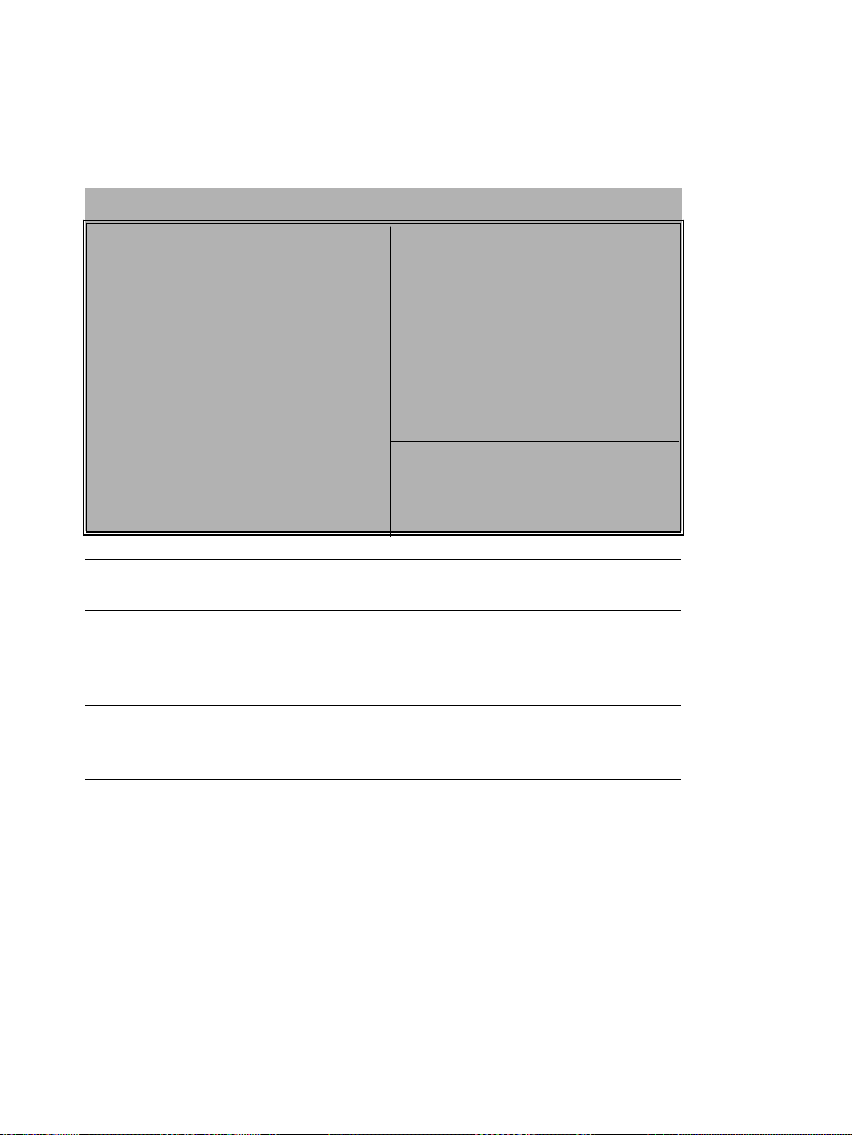
PCI / Plug and Play Setup
This page sets some of the parameters for devices installed on the PCI bus and
devices that use the system plug and play capability.
AMIBIOS SETUP – PCI / PLUG AND PLAY SETUP
©1998 American Megatrends, Inc. All Rights Reserved
Plug and Play Aware O/S Yes
Primary Graphics Adapter OnBoard VGA
Assign IRQ for VGA Yes
ESC : Quit : Select Item
F1 : Help PU/PD/+/- : Modify
F5 : Old Values (Shift)F2 : Color
F6 : Load Optimal values
F7 : Load Best performance values
Plug and Play
Aware O/S
Enable this item when your O/S is supportive
for Plug and Play such as Windows 95 or 98.
Primary Graphics
Adapter
The Graphics OnBoard was set to be Primary.
The default PCI onboard display is able to work
simultaneously with the second display card
installed in a PCI slot.
Assign IRQ for
VGA
If this item is set to Yes, an IRQ will be
assigned to VGA graphics system. If it’s set to
be No, an IRQ is released.
24
Page 25

BIOS Setup
Load Best Performance Settings
When you press <Enter> on this item, a dialog box appears as below:
Load Best Performance Defaults (Y/N) ? N
Pressing ‘Y’ loads the BIOS default values for the most stable, minimalperformance system operations.
Load Optimized Defaults
When you press <Enter> on this item you get a confirmation dialog box
with a message likely to :
Load Optimized Defaults (Y/N) ? N
Pressing ‘Y’ loads the default values that are factory settings for optimal performance system operation.
25
Page 26
BIOS Setup
Features Setup
This page sets some of the parameters for peripheral devices connected to the
system.
AMIBIOS SETUP – FEATURES SETUP
©1998 American Megatrends, Inc. All Rights Reserved
OnBoard FDC Enabled
OnBoard Serial Port1 3F8h/COM1
OnBoard IR Port2 Disabled
Ir Function Disabled
Ir Duplex Mode N/A
OnBoard Parallel Port 378h
Parallel Port Mode Normal
Parallel Port IRQ 7
Parallel Port DMA N/A
OnBoard Midi Port 300h
Midi Port IRQ Select 9
OnBoard Game Port 208h
OnBoard IDE Both
Ultra DMA Support Disabled
OnBoard USB Function Enabled
USB Function for DOS Disabled ESC : Quit : Select Item
TV OUT Type NTSC F1 : Help PU/PD/+/- : Modify
OnBoard Sound/Modem Enabled F5 : Old Values (Shift)F2 : Color
OnBoard LAN Enabled F6 : Load Optimal values
F7 : Load Best performance values
OnBoard FDC
Enable or disable the onboard floppy disk drive
interface.
OnBoard Serial
Port1
Enable or disable the onboard COM1 serial
port, and to assign a port address
OnBoard Serial
Port1
Enable or disable the onboard COM2 serial
port, and to assign a port address
IR Function
To define the protocol for an infrared port if you
have installed an optional IR port. The choices
are IrDA and ASKIR.
IR Duplex Mode
To define if the optional infrared port is full duplex or half-duplex.
OnBoard Parallel
Port
Enable or disable the onboard LPT1 parallel
port, and to assign a port address.
26
Page 27

BIOS Setup
Parallel Port Mode
For setting the parallel port mode. You can
select SPP (Standard Parallel Port), ECP
(Extended Capabilities Port), EPP (Enhanced
Parallel Port), or ECP + EPP.
Parallel Port IRQ
Assign either IRQ 5 or 7 to the parallel port.
Parallel Port DMA
Assign a DMA channel to the parallel port. The
options are 0, 1 and 3.
Onboard Midi Port
Enable or disable the onboard MIDI port, and to
assign a port address.
Midi Port IRQ
For assigning an IRQ to the MIDI port.
OnBoard Game
Port
Enable or Disable the Onboard Game Port, and
to assign a port address.
OnBoard IDE
Enable or Disable either or both of the Onboard
Primary and Secondary IDE channels.
Ultra DMA Support
For setting DMA to support IDE devices on the
Primary or Secondary IDE channels.
OnBoard USB
Function
Enable this item for using USB ports onboard.
USB Function for
DOS
Enable this item for using USB onboard under a
DOS environment.
TV Out type
TV Out kit support NTSC and PAL system.
OnBoard
Sound/Modem
Enable or Disable onboard audio/modem.
OnBoard LAN
Enable or Disable onboard LAN device.
27
Page 28
BIOS Setup
CPU PnP Setup
This page lets you manually configure the mainboard for the CPU. The system will
automatically detect the kind of CPU that you have installed and make the
appropriate adjustments to the items on this page.
Note: If you manually set the wrong speed and the system won’t run properly, press
the Page Up key while the system is booting and a default setting will replace the
incorrect CPU setting.
AMIBIOS SETUP – CPU PnP SETUP
©1998 American Megatrends, Inc. All Rights Reserved
CPU Type
CPU Speed Manual
CPU Core Voltage
CPU Ratio x4.5
CPU Frequency. 133 MHz
ESC : Quit : Select Item
F1 : Help PU/PD/+/- : Modify
F5 : Old Values (Shift)F2 : Color
F6 : Load Optimal values
F7 : Load Best performance values
CPU Type
CPU Core Voltage
These two items display the type and the core
voltage of installed CPU
CPU
Speed/Ratio/Frequ
ency
Use this item to set the internal clock speed.
When it’s set to Manual, the CPU speed equal
to the CPU Ratio (Multiplier) x CPU external
Frequency (i.e. CPU clock).
28
Page 29

BIOS Setup
Hardware Monitor
This page is for sttting the parameters of hardware monitoring function.
AMIBIOS SETUP – HARDWARE Monitor
©1998 American Megatrends, Inc. All Rights Reserved
--- System Hardware Monitor --CPU Socket 370 Temp. 30°C/86°F
Sytem Temp 24°C/86°F
CPU Fan Speed
Chassis Fan Speed
Vcore 2.000 V
Vcc +1.8V 1.800 V
Vcc +3.3V 3.3.00 V
Vcc +5.0V 5.000 V
Board +12V 12.000 V
ESC : Quit : Select Item
F1 : Help PU/PD/+/- : Modify
F5 : Old Values (Shift)F2 : Color
F6 : Load Optimal values
F7 : Load Best performance values
CPU / System
Temp.
Display of CPU and the system temperature
measurement.
FAN Speed &
Voltage
Measurements
Indication of cooling fan speeds in RPM and the
various system voltage measurements.
29
Page 30

BIOS Setup
Change Password
If you highlight this item and press Enter, a dialog box appears which lets you enter
a Supervisor password. You can enter no more than six letters or numbers. Press
Enter after you have typed in the password. A second dialog box asks you to retype
the password for confirmation. Press Enter after you have retyped it correctly. The
password is then required to access the Setup Utility or for that and at start-up,
depending on the setting of the Password Check item in Advanced Setup.
Highlight this item, press Enter and type in the current password. At the next dialog
box, type in the new password, or just press Enter to disable password protection.
Change or Remove the Password
Highlight this item, press Enter and type in the current password. At the next dialog
box, type in the new password, or just press Enter to disable password protection.
Exit
Highlight this item and press Enter to save the changes that you have made in the
Setup Utility configuration and exit the program. When the Save and Exit dialog
box appears, press Y to save and exit, or press N to exit without saving.
30
Page 31
Driver & Software
Driver & Software
Installation Guide
This driver is for Windows 95/NT/2000 and Win. 98. Aside from the installation
procedure differs from the Operating System used, the automatic installation is
only available for Windows 98.
Quick Installation under Windows 98
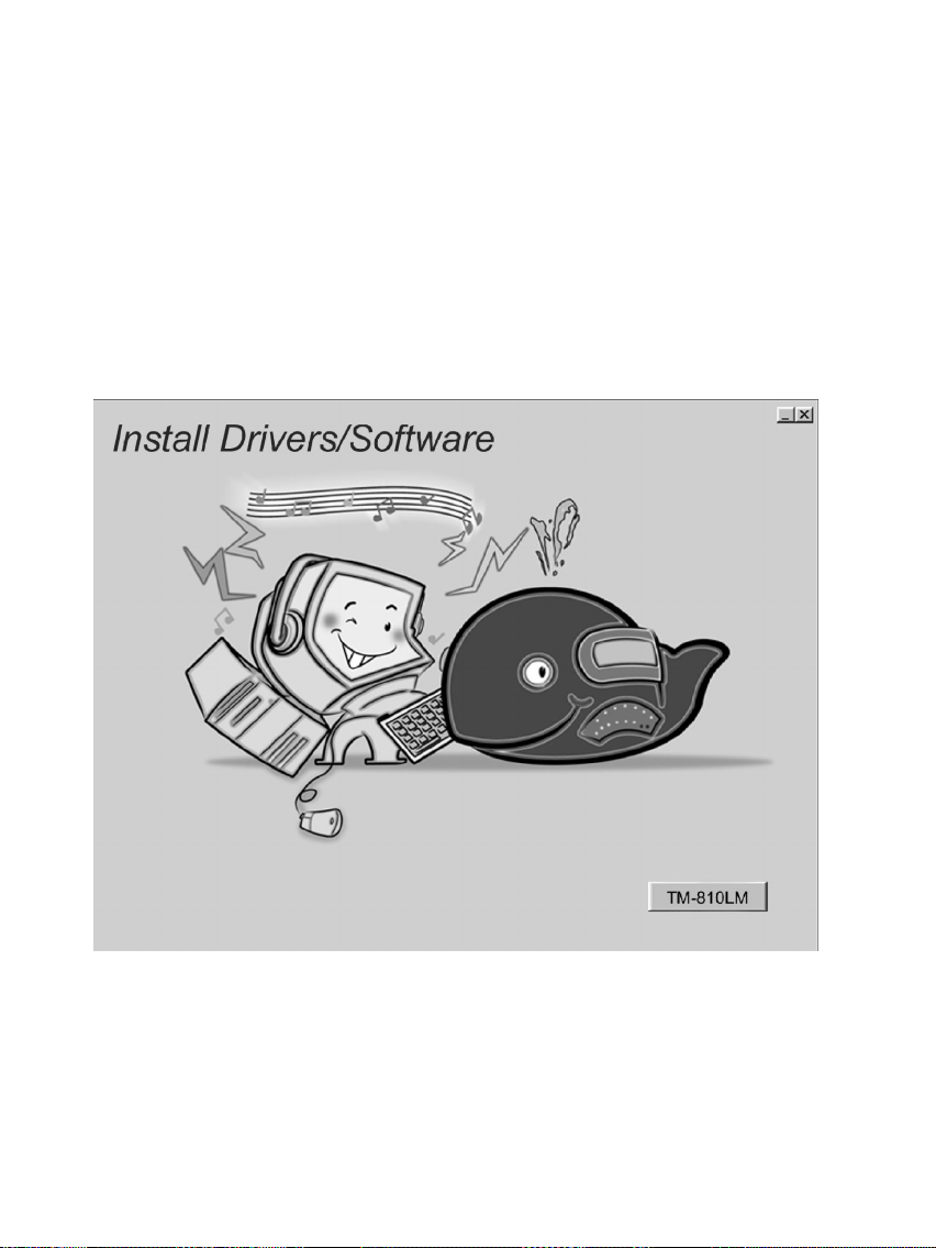
When insert the CD-ROM disc in the system CD-ROM drive, the set up feature will
automatically come up the screen with buttons for selecting mainboard models’
name as follows:
31
Page 32
Driver & Software
Browse All The Drivers in CD
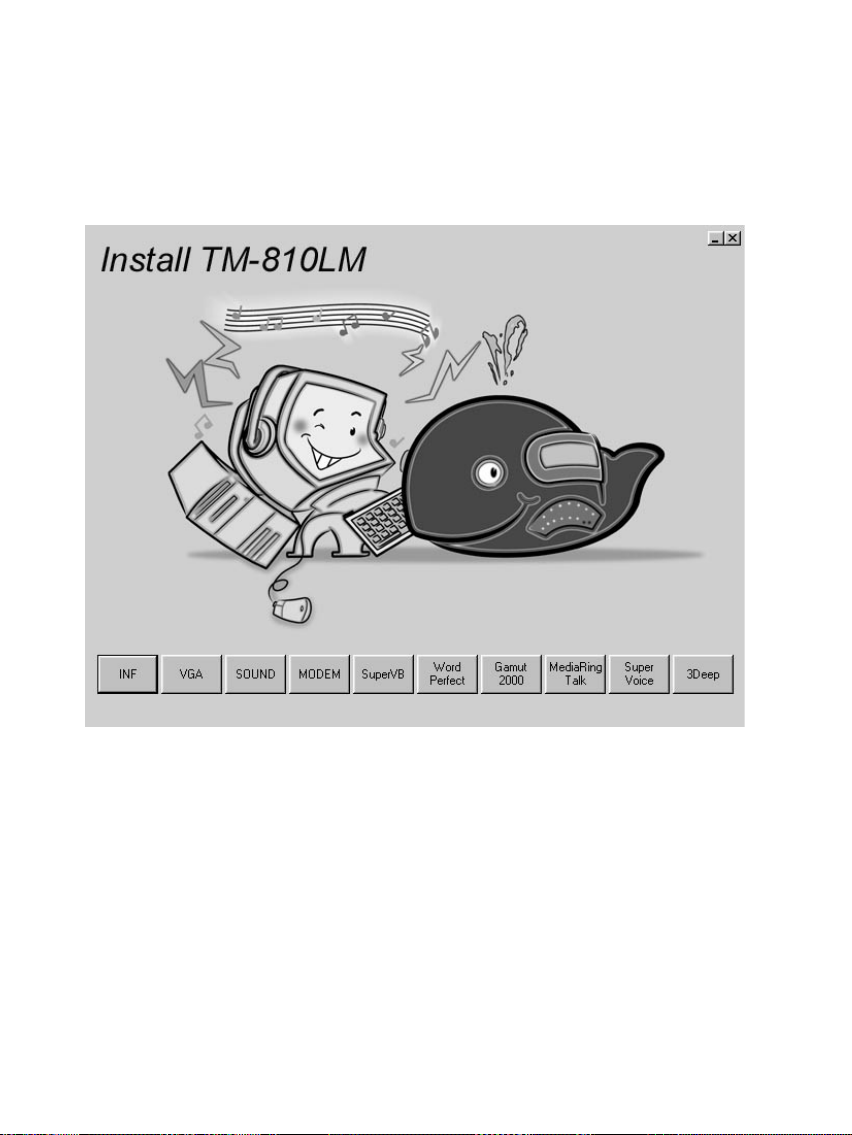
After selecting mainboard model name, all the available drivers will appears on the
screen as follows:
How to install Windows 95/NT/2000 ?
32
Page 33

Driver & Software
The procedure :
1. Insert the support CD-ROM disc in the CD-ROM drive.
(Just bypass the error message from the PnP function.)
2. Since quick installation is not supported by Windows 95/NT/2000, you have
to select correct drivers and EXE given file names as follows:
Bus Master IDE Driver
Win9x - \IDE\INTEL810\WIN9X\DISK1\SETUP.EXE
USB Driver
Win95 - \OTHERS\USB\EUSBSUPP\USBSUPP.EXE
Win95(Chinese) - OTHERS\USB\CUSBSUPP\CUSBSUPP.EXE
Audio Driver
OS & Windows 3.x - \SOUND\C-MEDIA\DOSDRV\
indows 9x - \SOUND\C-MEDIA\W95-98\DRV\
Windows NT - \SOUND\C-MEDIA\NT40\DRV\
Windows 2000 - \SOUND\C-MEDIA\W2K\DRV\
Audio Applications
Windows 9x - \GAMUT\SETUP.EXE
Display Drivers and Software
\VGA\INTEL810\WIN9X\GRAPHICS\SETUP.EXE
Path for updating Display Driver
Windows 9x - \VGA\INTEL810\WIN9X\GRAPHICS\
Windows NT - \VGA\INTEL810\WINNT4\
Windows 2000 - \VGA\INTEL810\WIN2000\
3Deep
DEEP\3DEEP 3.3\SETUP\SETUP.EXE
Fax/Modem Drivers and Software
Windows 9x,NT - \MODEM\PCI\9XNT\SETUP.EXE
Windows 2000 - \MODEM\PCI\WIN2000\
33
Page 34

Driver & Software
Windows ME - \MODEM\PCI\WINME\
Super Voice
\SUPER VOICE\PICSHELL.EXE
MediaRing Talk
\MEDIARING TALK\MRTALK-SETUP7.2.EXE
LAN Driver
Windows 9x,2000 - \LAN\DAVICOM\WIN2K_9X\
Windows NT - \LAN\DAVICOM\WINNT40\
Windows ME - \LAN\DAVICOM\WINME\
Corel WordPerfect Suite 8
\CD1\COREL\SUITE8\APPMAN\SETUP\SETUP.EXE
BIOS Update
\UTILITY\AMIFL818.EXE
Super VB Software
This software provides anti-virus protection PC.
\SUPERVB\AUTO.EXEWin9x – :\IDE\GFXPRO\Setup.exe
USB Driver
Win95 – :\Others\USB\EUSBSUPP\USBSUPP.EXE
Win95 (Chinese) – :\Others\USB\CUSBSUPP\CUSBSUPP.EXE
Further Guide to Audio Software :
1. Making sure the Operating System has been properly installed prior to the
installation of the PCI Sound Drivers. Otherwise, the Onboard PCI Audio might
be recognized as an “Other Device”.
34
Page 35

Driver & Software
2. For featuring Wave-Table drivers as a MIDI output device, just select
MULTIMEDIA from the Control Panel. Select the MIDI tab → Click “C-
media SoftMidi Synthesis ( Win 98) / Driver ( Win 95)” → Click OK to
complete.
3. Audio Rack, a Windows application, is provided to control all the Audio
functions for simply working as a high quality home stereo system.
4. For featuring MIDI port as the control interface, just select MULTIMEDIA from
the Control Panel. Select the MIDI tab → Click “C-M8738 MPU-401” (Win
98) or “DM8738/C3DX PCI Audio External MIDI Port” (Win 95) → Click
OK to complete.
The Four Speakers System
This onboard Audio System supports 2 wave channels (Front/rear) known as the 4
speakers system. For achieving simulation of realistic 3D sound effect through a 4
speakers, just to run applications which is featured with DirectSound 3D or A3D
Audio interface.
Mixer Setup
After setting up the PCI Audio Application, a 4-speakers option appears in the the
Mixer. Just click on the 4 Speakers icon to achieve this option. The rear speakers
will output only via Line-in/Rear jack now. So, when Line-in/Rear jack is occupied
by a Line-in device, Do Not enable this option to avoid hardware conflict.
35
Page 36
Technical Information
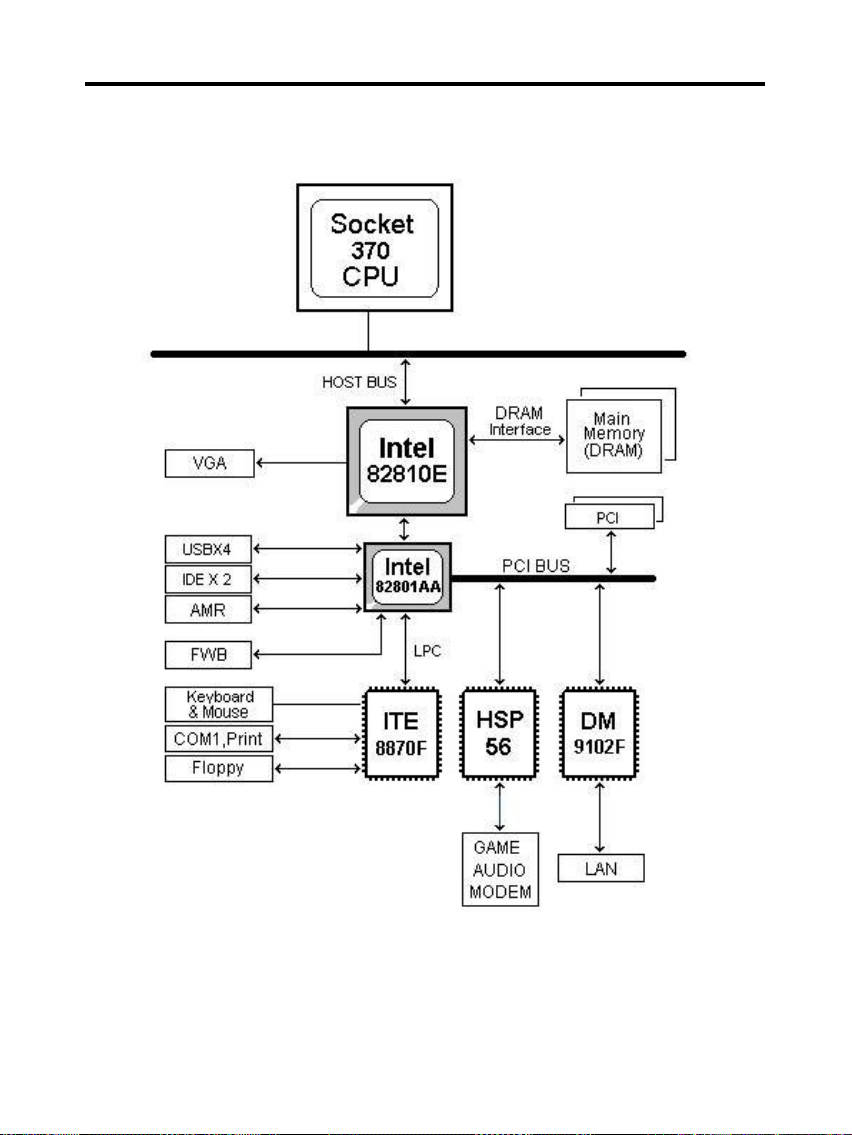
System Block Diagram
36
Page 37
Technical Information
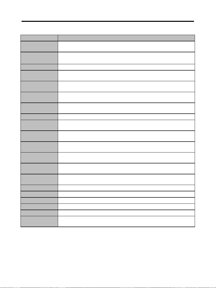
AMI BIOS POST Code :
POST (HEX) Description
C2
NMI is Disabled.
Power on delay starting.
C5
Power on delay complete.
Going to disable Cache if any.
C6
Calculating ROM BIOS checksum.
C7
ROM BIOS checksum passed.
CMOS shutdown register test to be done next.
C8
CMOS shutdown register test done. CMOS checksum calculation
to be done next.
CA
CMOS checksum calculation is done, CMOS Diag byte written.
CMOS status register about to init for Date and Time.
CB
CMOS status register init done.
Any initialization before keyboard BAT to be done next.
CD
BAT command to keyboard controller is to be issued.
CE
Keyboard controller BAT result verified.
Any initialization after KB controller BAT to be done next.
CF
Initialization after KB controller BAT done.
Keyboard command byte to be written next.
D1
Keyboard controller command byte is written.
Going to check pressing of <INS> key during power-on.
D2
Checking for pressing of <INS> key during power-on done.
Going to disable DMA and Interrupt controllers.
D3
DMA controller #1,#2, interrupt controller #1,#2 disabled.
Chipset init/ auto memory detection about to begin.
D4
Chipset initialization/ auto memory detection over.
To uncompress the RUNTIME code.
D5
RUNTIME code is uncompressed.
DD
Transfer control to uncompressed code in shadow ram at F000:FFF0.
03
NMI is Disabled. To check soft reset/power-on.
05
Soft reset/power-on determined. Going to disable Cache if any.
06
POST code to be uncompressed.
07
POST code is uncompressed.
CPU init and CPU data area init to be done next
37
Page 38
Technical Information
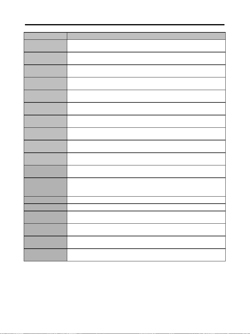
POST (HEX) Description
08
CPU and CPU data area init done.
CMOS checksum calculation to be done next.
09
CMOS checksum calculation is done, CMOS Diag byte written.
CMOS init to begin (If "Init CMOS in every boot” is set).
0A
CMOS initialization done (if any).
CMOS status register about to init for Date and Time.
0B
CMOS status register init done.
Any initialization before keyboard BAT to be done next.
0C
KB controller I/B free.
Going to issue the BAT command to keyboard controller.
0D
BAT command to keyboard controller is issued.
Going to verify the BAT command.
0E
Keyboard controller BAT result verified.
Any initialization after KB controller BAT to be done next.
0F
Initialization after KB controller BAT done.
Keyboard command byte to be written next.
10
Keyboard controller command byte is written.
Going to issue Pin-23,24 blocking/unblocking command.
11
Pin-23,24 of keyboard controller is blocked/ unblocked.
Going to check pressing of <INS> key during power-on.
12
Checking for pressing of <INS> key during power-on done.
Going to disable DMA and Interrupt controllers.
13
DMA controller #1,#2, interrupt controller #1,#2 disabled.
Video display is disabled and port-B is initialized.
Chipset init about to begin.
15
Chipset initialization over. 8254 timer test about to start.
19
8254 timer test over. About to start memory refresh test.
1A
Memory Refresh line is toggling.
Going to check 15 micro second ON/OFF time.
20
Memory Refresh period 30 micro second test complete.
Base 64K memory to be initialized.
23
Base 64K memory initialized. Going to set BIOS stack and to do
any setup before Interrupt vector init.
24
Setup required before interrupt vector initialization complete.
Interrupt vector initialization about to begin.
38
Page 39
Technical Information
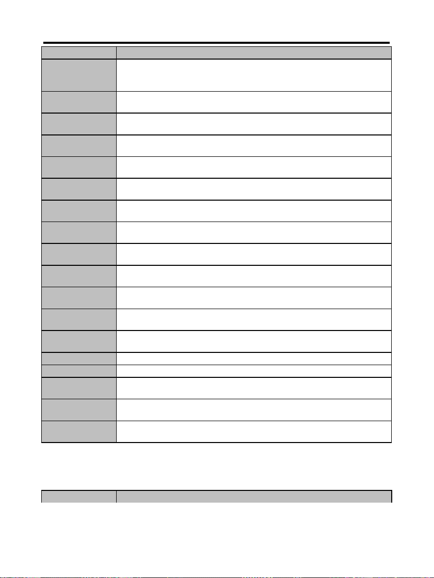
POST (HEX) Description
25
Interrupt vector initialization done.
Going to read Input port of 9042 for turbo switch (if any)
and to clear password if post diag switch is on.
26
Input port of 8042 is read.
Going to initialize global data for turbo switch.
27
Global data initialization for turbo switch is over.
Any initialization before setting video mode to be done next.
28
Initialization before setting video mode is complete.
Going for monochrome mode and color mode setting.
2A
Different BUSes init (system, static, output devices) to start if present.
(Please see Appendix for details of different BUSes).
2B
About to give control for any setup required before optional
video ROM check.
2C
Processing before video ROM control is done.
About to look for optional video ROM and give control.
2D
Optional video ROM control is done. About to give control
to do any processing after video ROM returns control.
2E
Return from processing after the video ROM control.
If EGA/VGA not found then do display memory R/W test.
2F
EGA/VGA not found.
Display memory R/W test about to begin.
30
Display memory R/W test passed.
About to look for the retrace checking.
31
Display memory R/W test or retrace checking failed.
About to do alternate Display memory R/W test.
32
Alternate Display memory R/W test passed.
About to look for the alternate display retrace checking.
34
Video display checking over. Display mode to be set next.
37
Display mode set. Going to display the power on message.
38
Different BUSes init (input, IPL, general devices) to start if present.
(Please see Appendix for details of different BUSes).
39
Display different BUSes initialization error messages.
(Please see Appendix for details of different BUSes).
3A
New cursor position read and saved.
Going to display the Hit <DEL> message.
POST (HEX) Description
39
Page 40
Technical Information
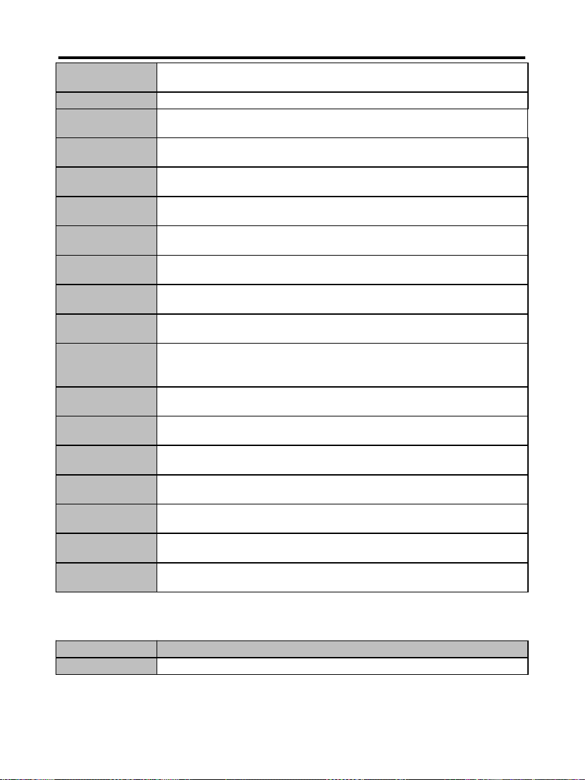
3B
Hit <DEL> message displayed.
Virtual mode memory test about to start.
40
Going to prepare the descriptor tables.
42
Descriptor tables prepared.
Going to enter in virtual mode for memory test.
43
Entered in the virtual mode.
Going to enable interrupts for diagnostics mode.
44
Interrupts enabled (if diagnostics switch is on).
Going to initialize data to check memory wrap around at 0:0.
45
Data initialized. Going to check for memory wrap around at 0:0
and finding the total system memory size.
46
Memory wrap around test done. Memory size calculation over.
About to go for writing patterns to test memory.
47
Pattern to be tested written in extended memory.
Going to write patterns in base 640k memory.
48
Patterns written in base memory.
Going to findout amount of memory below 1M memory.
49
Amount of memory below 1M found and verified.
Going to findout amount of memory above 1M memory.
4B
Amount of memory above 1M found and verified.
Check for soft reset and going to clear memory below 1M for
soft reset. (If power on, go to check point# 4Eh).
4C
Memory below 1M cleared. (SOFT RESET)
Going to clear memory above 1M.
4D
Memory above 1M cleared. (SOFT RESET)
Going to save the memory size. (Goto check point# 52h).
4E
Memory test started. (NOT SOFT RESET)
About to display the first 64k memory size.
4F
Memory size display started. This will be updated during
memory test. Going for sequential and random memory test.
50
Memory testing/initialization below 1M complete.
Going to adjust displayed memory size for relocation/ shadow.
51
Memory size display adjusted due to relocation/ shadow.
Memory test above 1M to follow.
52
Memory testing/initialization above 1M complete.
Going to save memory size information.
POST (HEX) Descriptions
53
Memory size information is saved. CPU registers are saved.
40
Page 41
Technical Information
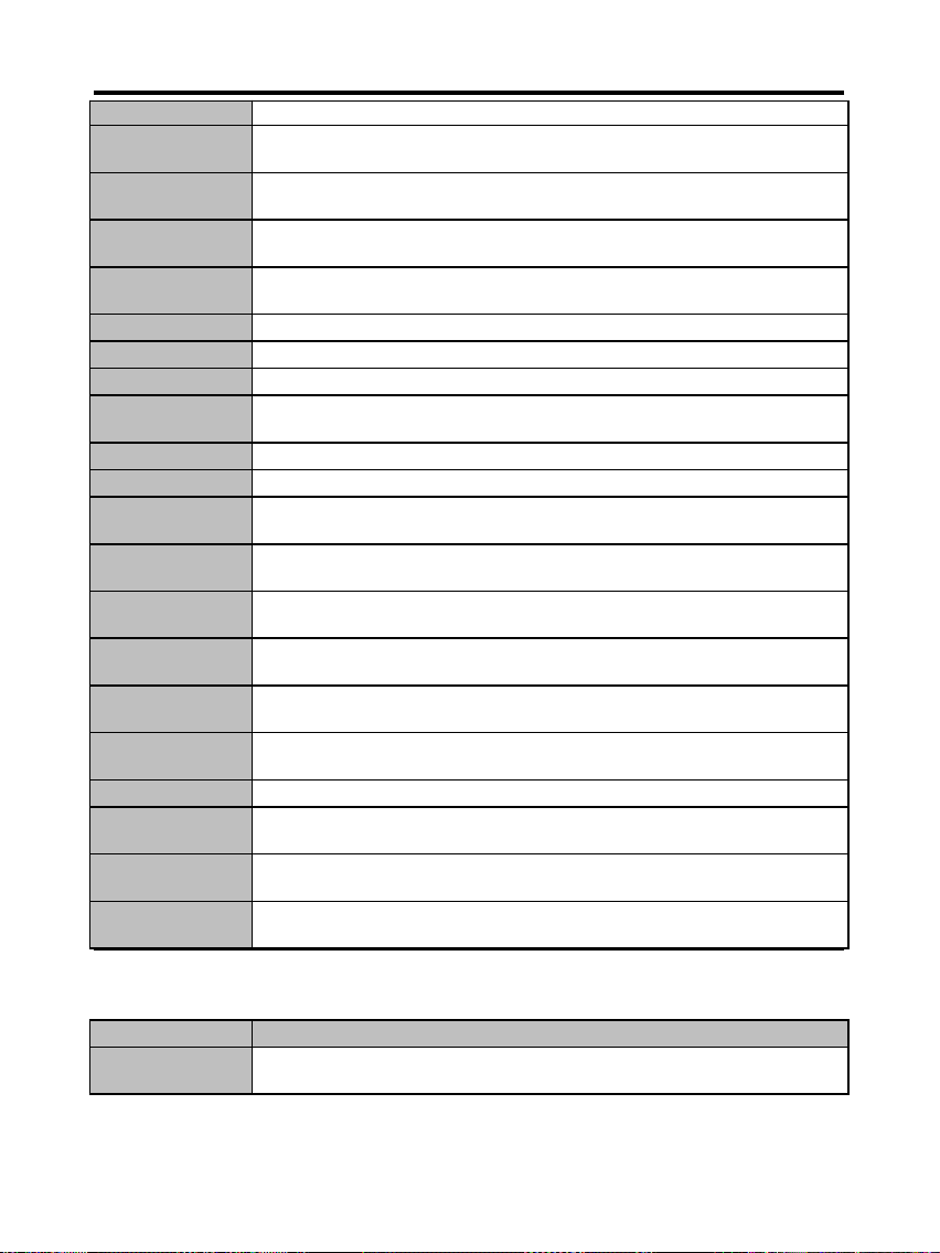
Going to enter in real mode.
54
Shutdown successful, CPU in real mode. Going to disable
gate A20 line and disable parity/NMI.
57
A20 address line, parity/NMI disable successful.
Going to adjust memory size depending on relocation/shadow.
58
Memory size adjusted for relocation/shadow.
Going to clear Hit <DEL> message.
59
Hit <DEL> message cleared. <WAIT...> message displayed.
About to start DMA and interrupt controller test.
60
DMA page register test passed. To do DMA#1 base register test.
62
DMA#1 base register test passed. To do DMA#2 base register test.
65
DMA#2 base register test passed. To program DMA unit 1 and 2.
66
DMA unit 1 and 2 programming over.
To initialize 8259 interrupt controller.
67
8259 initialization over.
7F
Extended NMI sources enabling is in progress.
80
Keyboard test started. clearing output buffer, checking
for stuck key, About to issue keyboard reset command.
81
Keyboard reset error/stuck key found. About to
issue keyboard controller interface test command.
82
Keyboard controller interface test over.
About to write command byte and init circular buffer.
83
Command byte written, Global data init done.
About to check for lock-key.
84
Lock-key checking over.
About to check for memory size mismatch with CMOS.
85
Memory size check done. About to display soft error
and check for password or bypass setup.
86
Password checked. About to do programming before setup.
87
Programming before setup complete.
Going to uncompress SETUP code and execute CMOS setup.
88
Returned from CMOS setup program and screen is cleared.
About to do programming after setup.
89
Programming after setup complete.
Going to display power on screen message.
POST (HEX) Description
8B
First screen message displayed. <WAIT...> message displayed.
About to do Video BIOS shadow.
41
Page 42
Technical Information
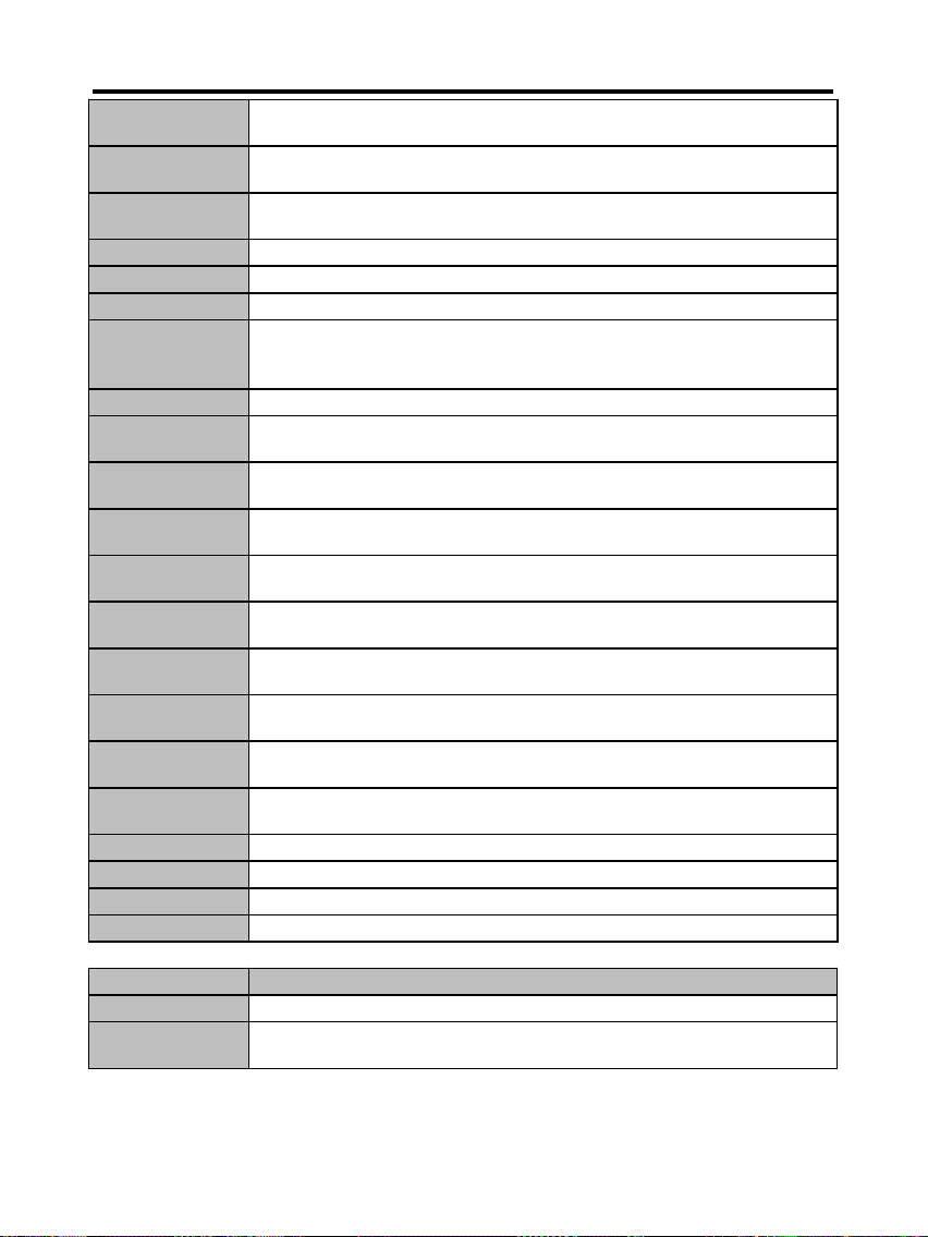
8C
Video BIOS shadow successful.
Setup options programming after CMOS setup about to start.
8D
Setup options are programmed, mouse check and init
to be done next.
8E
Mouse check and initialization complete.
Going for hard disk controller reset.
8F
Hard disk controller reset done. Floppy setup to be done next.
91
Floppy setup complete. Hard disk setup to be done next.
94
Hard disk setup complete. To set base and extended memory size.
95
Memory size adjusted due to mouse support.
Init of different BUSes optional ROMs from C800 to start.
(Please see Appendix-I for details of different BUSes).
96
Going to do any init before C800 optional ROM control.
97
Any init before C800 optional ROM control is over.
Optional ROM check and control will be done next.
98
Optional ROM control is done. About to give control to do
any required processing after optional ROM returns control.
99
Any initialization required after optional ROM test over.
Going to setup timer data area and printer base address.
9A
Return after setting timer and printer base address.
Going to set the RS-232 base address.
9B
Returned after RS-232 base address.
Going to do any initialization before Coprocessor test.
9C
Required initialization before Coprocessor is over.
Going to initialize the Coprocessor next.
9D
Coprocesor initialized.
Going to do any initialization after Coprocessor test.
9E
Initialization after Coprocessor test is complete.
Going to check extd keyboard, keyboard ID and num-lock.
9F
Extd keyboard check is done, ID flag set, num-lock on/off.
Keyboard ID command to be issued.
A0
Keyboard ID command issued. Keyboard ID flag to be reset.
A1
Keyboard ID flag reset. Cache memory test to follow.
A2
Cache memory test over. Going to display any soft errors.
A3
Soft error display complete. Going to set keyboard typematic rate.
POST (HEX) Description
A4
Keyboard typematic rate set. To program memory wait states.
A5
Memory wait states programming over.
Going to clear the screen and enable parity/NMI.
42
Page 43
Technical Information
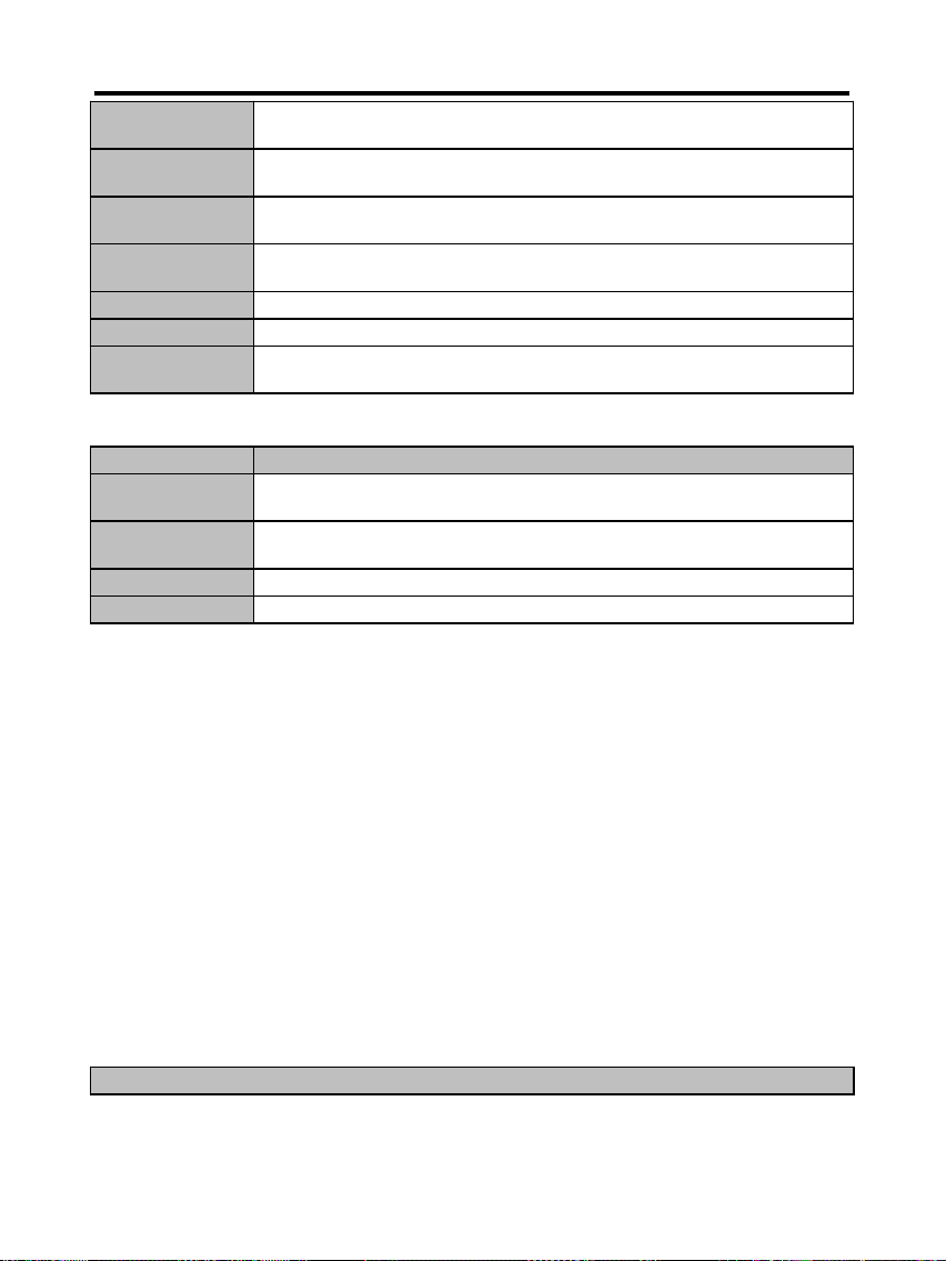
A7
NMI and parity enabled. Going to do any initialization
required before giving control to optional ROM at E000.
A8
Initialization before E000 ROM control over.
E000 ROM to get control next.
A9
Returned from E000 ROM control. Going to do any
initialization required after E000 optional ROM control.
AA
Initialization after E000 optional ROM control is over.
Going to display the system configuration.
B0
System configuration is displayed.
B1
Going to copy any code to specific area.
00
Copying of code to specific area done.
Going to give control to INT-19 boot loader.
APPENDIX:
CHECK-POINT Description of CHECK-POINT
2A
Different BUSes init (system, static, output devices) to
start if present.
38
Different BUSes init (input, IPL, general devices) to start
if present.
39
Display different BUSes initialization error messages.
95
Init of different BUSes optional ROMs from C800 to start.
Problem Sheet
To conduct correct diagnosis and repairing work, you were requested to fill
this RMA from and attach it with each RMA mainboard before sending back
for repairing.
Customer
43
Page 44
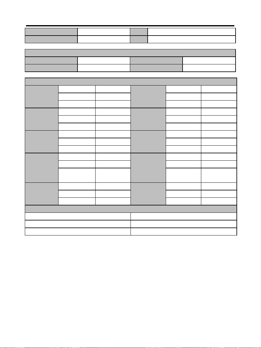
Technical Information
Name Tel
address Fax
Mainboard
Mode Mainboard Rev
Serial No. BIOS version
Peripherals Description
Brand Brand
CPU Type RAM Type & Size
Voltage Speed
Brand Brand
Floppy disk Mode VGA card Chipset
Size RAM Type
Brand Brand
Hard disk Mode CD-ROM Mode
Size Speed
Brand Brand
Sound card Mode Lan card Mode
Remark PCI/ISA
Bus
Brand Brand
Mouse Mode O.S Name
PS/2 or Serial
Version
Problem Description
MEMO
44
 Loading...