

Page 1

This publication, photographs, illustrations and software are under
the protection of international copyright laws and all rights
reserved. It does not allow any reproduction of this manual,
content and any materials contained herein without the written
consent of the authentic manufacturer.
The information in this manual is subject to change without notice.
The manufacturer does neither represent nor warrant the contents
hereof; and specifically disclaims any implied warranties of
merchantability or fitness for any particular purpose. Furthermore,
the manufacturer reserves the right to revise and change this
publication from time to time, without the obligation of notifying
any person of such revision or changes.
Trademarks
IBM, VGA, and PS/2 are registered trademarks of International
Business Machines.
Intel, Pentium/II/III, Pentium 4, Celeron and MMX are registered
trademarks of Intel Corporation.
Microsoft, MS-DOS and Windows 98/ME/NT/2000/XP are
registered trademarks of Microsoft Corporation.
PC-cillin is a trademark of Trend Micro Inc.
AMI is a trademark of American Megatrends Inc.
It has been acknowledged that other brands or product names in
this manual are trademarks or the properties of their respective
owners.
Copyright © 2003
All Rights Reserved
T10 Series, V1.2B
I848P/December 2003
Page 2

Table of Contents
Trademark.....................................................................................I
Static Electricity Precautions.................................................III
Pre-Installation Inspection .....................................................III
Features & Checklist Translations.............................................. V
Chapter 1: Introduction.................................................................1
Key Features.............................................................................2
Package Contents......................................................................6
Chapter 2: Mainboard Installation................................................7
Mainboard Components ...........................................................8
I/O Ports....................................................................................8
Installing the Processor.............................................................9
Installing Memory Modules ...................................................10
Jumper Settings.......................................................................11
Install The Mainboard ............................................................12
Connecting Optional Devices.................................................13
Install Other Devices ..............................................................15
Expansion Slots .....................................................................17
Chapter 3: BIOS Setup Utility.....................................................18
Introduction ............................................................................18
Running the Setup Utility............…………………………...19
Standard CMOS Setup Page...................................................20
Advanced Setup Page.............................................................21
Features Setup Page................................................................22
Power Management Setup Page .............................................23
PCI/Plug and Play Setup Page................................................25
BIOS Security Features Setup Page .......................................26
CPU PnP Setup Page..............................................................27
Hardware Monitor Page..........................................................28
Load Optimal Defaults ...........................................................28
Save Changes and Exit. .........................................................28
Discard Changes and Exit. .....................................................29
Chapter 4: Software & Applications ..........................................30
Introduction ............................................................................30
Installing Support Software....................................................31
Bundled Software Installation................................................33
Hyper Threading CPU............................................................34
Appendix ................................................................................35
II
Page 3

Static Electricity Precautions
Static electricity could damage components on this mainboard.
Take the following precautions while unpacking this mainboard
and installing it in a system.
1. Don’t take this mainboard and components out of their original
static-proof package until you are ready to install them.
2. While installing, please wear a grounded wrist strap if possible.
If you don’t have a wrist strap, discharge static electricity by
touching the bare metal of the system chassis.
3. Carefully hold this mainboard by its edges. Do not touch those
components unless it is absolutely necessary. Put this
mainboard on the top of a static-protection package with
component side facing up while installing.
Pre-Installation Inspection
1. Inspect this mainboard whether there are any damages to
components and connectors on the board.
2. If you suspect this mainboard has been damaged, do not
connect power to the system. Contact your mainboard vendor
about those damages.
III
Page 4
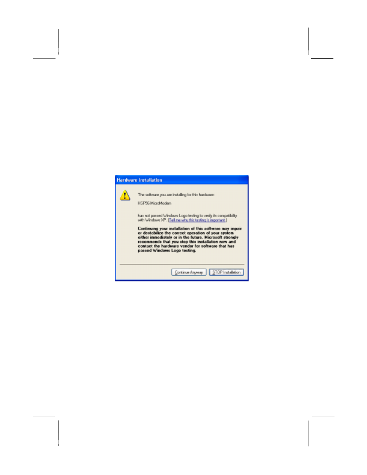
Notice:
Owing to Microsoft’s certifying schedule is various to every
supplier, we might have some drivers not certified yet by
Microsoft. Therefore, it might happen under Windows XP that a
dialogue box (shown as below) pop out warning you this
software has not passed Windows Logo testing to verify its
compatibility with Windows XP. Please rest assured that our RD
department has already tested and verified these drivers. Click
the “Continue Anyway” button and go ahead the installation.
IV
Page 5
Features & Checklist Translations
Liste de contrôle
Le coffret de votre carte mère contient les éléments suivants :
La carte mère
Le Manuel utilisateur
Un câble plat pour lecteur de disquette (optionnel)
Une câble plat pour lecteur IDE
CD de support de logiciels
Features
Processeur
Prise en charge du Processeur Socket-478
• Supporte le CPU Intel Pentium 4 series avec la Technologie Hyper
Threading
• Supporte un Bus Avant allant jusqu’à 800 MHz
La technologie “Hyper-Threading” permet au système d’exploitation de
penser qu’il est connecté à deux processeurs, permettant d’exécuter deux
threads en parallèle, à la fois sur des processeurs ‘logiques’ dans le même
processeur physique.
Chipset
Support de
Mémoire
AC97 Audio
Codec
Ce chipset comporte Intel 848P Northbridge et Intel 82801EB I/O Controller
Hub (ICH5) conformément à une architecture novatrice et dimensionnable
avec une fiabilité et des performances prouvées.
• Support d’Interface d’Hôte: Fréquences FSB 64 bits de 400 MHz (horloge de
bus de 100 MHz), 533 MHz (horloge de bus de 133 MHz), et 800 MHz
(horloge de bus de 200 MHz); BW maximum théorique de 6.4 Go/s,
Technologie Hyper Threading
• Support de Contrôleur de Mémoire Système: Interface de mémoire DDR à
Canal simple (largeur de 64 bits), jusqu’à 2Go de mémoire système;
maximum de deux DIMM DDR, simple face et/ou double face
• Support d’Interface AGP: AGP 3.0 avec transferts de données AGP 4X/8X
et fast writes 4X/8X , respectivement.
• Interfact de Bus PCI supporte les Spécifications PCI Révision 2.3
• Contrôleur LAN intégré: Conforme WfM 2.0 et IEEE802.3
• Contrôleur d’Hôte ATA Série intégré: Opération DMA indépendante et
Vitesse de Transfert allant jusqu’à 1.5 Gb/s (150 Mo/s)
• Deux logements DIMM 184 broches pour modules mémoire
• Supporte le bus mémoire DDR400 MHz
• La mémoire maximum installée est 2Go
• L’architecture matérielle 6-CH permet au southbridge multi-canal de lire
l’audio 6CH
• Compatible Intel
PC2001
• Tampon d’écouteur intégré et PLL interne, le dernier cristal supplémentaire
d’économie
• Lignes d’entrée/ sortie arrière partageant la même prise ; Centre/basse
partageant la prise MIC
• Support de SORTIE S/PDIF numérique
3D: HRTF basé BS3D compatible moteur audio
• CRL
AC’97 (REV. 2.2), conforme aux exigences de Microsoft
V
Page 6
Logements
d’Extension
IDE Interne
ATA Série
Ports E/S
Internes
LAN Fast Ethernet (optionnel)
USB 2.0
• Six slots PCI 32 bits (Cinq Master PCI 1~5 et Un Slave PCI6)
• Un logement 8x AGP
• Un logement CNR (Communications and Networking Riser)
• Deux Connecteurs IDE
• Prend en Charge les modes PIO (Entrée/Sortie Programmable) et DMA
(Accès Direct à la Mémoire)
• Supporte maîtrise de bus Ultra DMA IDE avec vitesse de transfert de
33/66/100/133 Mo/sec
• Deux ATA Série connecteurs
• Vitesse de transfert supérieure au meilleur ATA (~150 Mo/s) avec
extensibilité aux vitesses supérieures
• Comptage de broche faible pour l’hôte et les périphériques
La carte mère possède un jeu complet de ports d’E/S et de connecteurs:
• Deux ports PS/2 pour souris et clavier
• Un port série
• Un port parallèle
• Huit ports USB 2.0 (quatre ports fond de panier, connecteurs USB internes
USB2/USB3 offrant quatre ports supplémentaires)
• Prises audio pour microphone, ligne d’entrée et ligne de sortie
• LAN Gigabit Interne:
− Emetteur-récepteur intégré 10/100/1000
− Auto Négotiation avec capacité de page Suivante
− Supporte le contrôle de flux en Full Duplex (IEEE 802.3x), et
marquage VLAN IEEE 802.1Q
− Entièrement conforme à IEEE 802.3, IEEE 802.3u, IEEE 802.3ab
• Onboard 10/100Mbps Ethernet LAN:
− Fonctionnement 10 Mb/s et 100 Mb/s
− Fast Ethernet MAC intégré, puce physique, et émetteur-récepteur sur
une seule puce
− Supporte l’auto-négociation N-way en 10Mb/s et 100Mb/s
− Supporte la gestion d’alimentation ACPI
− Contrôle de Flux en Full Duplex (IEEE 802.3x) et capacité Half/Full
duplex
• Conforme aux Spécifications de Bus Série Universel Révision 2.0
• Conforme aux Spécifications d’interface de Contrôleur d’Hôte Amélioré de
Intel Révision 0.95
• Conforme aux Spécifications d’Interface de Contrôleur d’Hôte Universel
Révision 1.1
• Le périphérique multifonction PCI consiste en deux noyaux de Contrôleur
d’Hôtes UHCI pour signalisation pleine/faible vitesse et un noyau de
Contrôleur d’Hôtes EHCI pour signalisation haute vitesse
• Le hub racine consiste en 4 ports de face en aval avec émetteurs-
récepteurs de couche physique intégrés partagés par le Contrôleur d’Hôte
UHCI et EHCI
• Support des Spécifications d’Interface de Gestion d’Alimentation de Bus
PCI version 1.1
• Support hérité pour tous les ports face à l’aval.
Certaines spécifications matérielles et éléments de logiciels peuvent être modifiés
sans avertissement.
VI
Page 7

Checkliste
Die Verpackung Ihres Mainboards enthält folgende Teile:
Mainboard
Handbuch
Bandkabel für Floppylaufwerke (optional)
Bandkabel für IDE-Laufwerke
Software-CD
Ausstattung
Prozessor
Unterstütz Socket-478-Prozessoren
• Unterstützung für Intel Pentium 4-CPUs mit “Hyper-Threading”-Technologie
• Unterstützung von bis zu 800 MHz Front-Side Bus
“Hyper-Threading”-Technologie läßt das Betriebssystem glauben, es sei
an zwei Prozessoren angeschlossen, was zwei parallele Threads auf
separaten ‘logischen’ Prozessoren im selben physischen Prozessor
erlaubt.
Chipsatz
Speicherunte
rstützung
AC97 Audio
Codec
Erweiterungs
steckplätze
Dieser Chipsatz besteht aus einer Intel 848P Northbridge und einer Intel
82801EB I/O Controller Hub (ICH5). Die Chipsatzarchitektur ist in einem
innovativen und skalierbaren Design gehalten und verspricht sowohl
Zuverlässigkeit als auch Leistungsstärke.
• Host-Unterstützungsschnittstelle: 64-Bit FSB auf Frequenzen von 400 MHz
(100 MHz Bus-Uhr), 533 MHz (133 MHz Bus-Uhr), und 800 MHz (200 MHz
Bus-Uhr); maximale theoretische Bandbreite von 6.4 GB/s, Hyper Threading
Technology
• Unterstützung der Speichersystemkontrolle: Ein-Kanal (64-Bit-Breite) DDRSpeicherschnittstelle, bis zu 2GB Systemspeicher; maximal zwei DDR
DIMMs, einzelseitig und/oder doppelseitig
• Unterstützung der AGP-Schnittstelle: AGP 3.0 mit 4X/8X AGP
Datenübertragungen und 4X/8X Schnellschreibungen, beziehungsweise.
• Die PCI Bus Schnittstelle unterstützt Spezifikationen von PCI Revision 2.3
• Integrierter LAN Controller: gemäß WfM 2.0 und IEEE802.3
• Integrierter Serien ATA Host Controller: Unabhängige DMA Operation and
Datenübertragungsrate bis zu 1.5 Gb/s (150 MB/s)
• Zwei 184-pin DIMM Steckplätze für DDR Speichermodule
• Unterstützung für DDR400MHz Speicherbus
• Maximal auf 2GB Speicher erweiterbar
• 6-CH Hardware-Architektur erlaubt einen Multikanal south bridge für die
6CH Tonwiedergabe
• Kompatibel mit Intel
Richtlinien
• Eingebauter Kopfhörer-Puffer und interner PLL, letzterer spart das
zusätzliche Kristall.
• Line-in/rear out (hinterer Ausgang) benutzen die gleiche Buchse;
Zentrum/Bass benutzen die gleiche MIC Buchse
• Digitale S/PDIF OUT Unterstützung
3D: BS3D kompatibler Audio Motor, basierend auf HRTF
• CRL
• Sechs 32-Bit PCI-Steckplätze (Fünf Master PCI 1~5 und Ein Slave PCI6)
• Ein 8xAGP-Steckplatz
AC’97 (REV. 2.2), gemäß Microsoft PC2001
VII
Page 8
• Ein CNR-Steckplatz
Onboard IDE
Serial ATA
Onboard I/O
Ports
Fast Ethernet
LAN
(optional)
USB 2.0
• Zwei IDE-Header
• Unterstützt die Modi PIO (Programmable Input/Output) und DMA (Direct
Memory Access)
• Unterstützung für IDE Ultra DMA-Busmastering mit Transferraten von
33/66/100/133 MB/Sek
• Zwei Serial ATA Headers
• Datentransferrate übertrifft beste ATA-Werte (~150 MB/Sek.); höhere
Transferraten möglich
• Low Pin Count (LPC) für Host und Geräte
Das Mainboard verfügt über einen kompletten Satz von I/O-Schnittstellen und
Anschlüssen:
• Zwei PS/2-Steckplätze für Maus und Tastatur yboard
• Ein serieller Steckplatz
• Ein paralleler Steckplatz
• Acht USB2.0-Ports (vier Ports auf der Rückseite; die Onboard-USB-Header
USB2/USB3 bieten vier zusätzliche USB-Ports).
• Audioanschlüsse für Mikrofon, line-in und line-out
• Onboard Gigabit LAN:
− Integrierter 10/100/1000 Transceiver
− Selbstverhandlung mit “Next page”- (nächste Seite) Kapazität
− Unterstützt eine Full Duplex Flußkontrolle (IEEE 802.3x), und IEEE
802.1Q VLAN-Markierung
− In Übereinstimmung mit IEEE 802.3, IEEE 802.3u, IEEE 802.3ab
• Onboard 10/100Mbps Ethernet LAN:
− 10 Mb/s und 100 Mb/s Betrieb
− Integrierter Fast Ethernet MAC, physikalischer Chip und Transceiver
in einem einzigen Chip
− Unterstützt 10Mb/s und 100Mb/s N-way Auto-Verhandlung
− Unterstüzt ACPI Versorgungs-Betriebssystem
− Fließende Full Duplex Kontrolle (IEEE 802.3x) und halbe/Full duplex
Kapazität
• Entspricht Universal Serial Bus-Spezifikation, Revision 2.0
• Entspricht Intels Enhanced Host Controller Interface-Spezifikation,
Revision 0.95
• Entspricht Universal Host Controller Interface -Spezifikation Revision 1.1
• PCI-Multifunktionsgerät besteht aus zwei UHCI Host Controller-Kernen für
Signalübertragung bei voller und niedriger Geschwindigkeit sowie einem
EHCI Host Controller-Kern für Hochgeschwindigkeits- Signalübertragung
• Root Hub besteht aus 4 Downstream-Ports mit integrierten Physical LayerÜberträgern für gemeinsame Nutzung durch UHCI und EHCI Host
Controller
• Unterstützt PCI-Bus Power Management Interface , Spezifikation Release
1.1
• Legacy-Unterstützung für alle Downstream-Ports
Bestimmte Hardwarespezifikationen und Teile der Softwareausstattung können ohne
weitere Ankündigung abgeändert werden.
VIII
Page 9

Lista
L’imballo della scheda madre é composto da:
La scheda madre
Il manuale
Una piattina per il collegamento dei drive (opzionale)
Una piattina IDE
Il CD con il Software di supporto
Caratteristiche
Processor
Dotata di Socket 478 per Processori
• Supporta CPU Intel Pentium serie 4 con tecnologia Hyper Threading
• Supporta fino a 800 MHz Front Side Bus
La tecnologia Hyper-Threading permette al sistema operative di essere
dotato di due procressori. Permettendovi di effettuare due operazioni in
parallelo, entrambe su processori ‘logici’ separati all’interno dello stesso
processore fisico.
Chipset
Memory
Support
AC97 Audio
Codec
Slot di
espansione
In accordo ad una archittettura scabile e innovative sono presenti nel chipset il
Northbridge Intel 848P e Intel 82801EB I/O Controller Hub (ICH5).
• Supporto Interface Host: Frequenze FSB a 64bit a 400 MHz (clock del bus a
100 MHz), 533 MHz (clock del bus a 133 MHz) ed 800 MHz (clock del bus a
200 MHz); BW massima teorica pari a 6.4 GB/s, supporto tecnologia Hyper
Threading
• Controller di Memoria di Sistema: Interfaccia DDR a canale singolo (64 bit),
Fino a 2GB di memoria di sistema; supporto Massimo di due DIMM DDR,
single-sided e/o double-sided
• Supporto Interfaccia AGP: AGP 3.0 con trasferimento dati AGP 4X/8X e fast
writes 4X/8X.
• Interfaccia PCI integrata: supporto delle specifiche PCI Rev. 2.3
• Interfaccia LAN integrata: supporto delle specifiche WfM 2.0 e IEEE802.3
• Controller Host Serial ATA intergrata: Operazioni DMA indipendente e
trasferimento dati Massimo fino a 1.5 Gb/s (150 MB/s)
• Due slot DIMM a 184 pin per moduli di memoria DDR
• Supporta bus di memoria DDR400 MHz
• Quantità massima di memoria installabile, 2GB
• Architettura hardware 6-CH che permette l’utilizzo del “multi-channel south
bridge” per la riproduzione 6CH
• Compatibilità con lo standard Intel
Microsoft
• buffer cuffie integrato e PLL interno, l’ultimo eliminando la necessità di
cristalli ulteriore
• Line-in/rear out condividono lo stesso jack;
• MIC e Center/bass condividono lo stesso jack
• Supporto S/PDIF OUT Digitale
• CRL
BS3D
• Sei slot PCI a 32 bit (Cinque Master PCI 1~5 e Una Slave PCI6)
• Una slot AGP 8x
• Una slot CNR
PC2001
3D: HRTF basata su un motore audio compatibile con lo standard
AC’97 (REV. 2.2) secondo i requisiti
IX
Page 10
Onboard IDE
ATA Seriale
Onboard I/O
Ports
Fast Ethernet LAN (opzionale)
USB 2.0
• Due connettori IDE
• Supporto della modalità PIO (Programmable Input/Output) e DMA (Direct
Memory Access)
• Supporto per le modalità Bus Mastering e Ultra DMA ATA 33/66100/133
MB/sec
• Due connettori Serial ATA
• Altissima velocità di trasferimento dati ATA (~150 MB/s) con la possibilità di
scalabilità della velocità stessa verso valori piú alti
• Pin Count ridotto sia per l’host sia per le periferich
La scheda madre è dotata da una serie completa di porte e connettori I/O:
• Due porte PS/2 per tastiera e mouse
• Una porta seriale
• Una porta parallela
• Otto porte USB2.0 (Quattro presenti nella parte posteriore, connettori USB
integrati nella scheda madre per l’aggiunta di altre 4 porte USB2/USB3
• Jack audio per microfono, ingresso linea e uscita linea
• LAN Gigabit integrata:
− transceiver 10/100/1000 Integrato
− Negoziazione automatica con capacità Next page
− Controllo flusso dati Full Duplex (IEEE 802.3x) e tagging VLAN IEEE
802.1Q
− Supporto degli standard IEEE 802.3, IEEE 802.3u e IEEE 802.3ab
• Onboard 10/100Mbps Ethernet LAN:
− Operazioni 10 Mb/s a 100 Mb/s
− Fast Ethernet MAC integrata, chip fisico e transceiver nello stesso
chip
− Supporto della negoziazione automatica N-way a 10Mb/s e 100Mb/s
− Supporto di gestione del consumo energetico ACPI
− Controllo di flusso Full Duplex (IEEE 802.3x) e Half/Full
• Conforme alle specifiche Universal Serial Bus 2.0
• Conforme alle specifiche Intel Enhanced Host Controller revisione 0.95
• Conforme alle specifiche Universal Host Controller Interface revisione 1.1
• Il dispositivo PCI multifunzione consiste di due schede di controllo UHCI per
la trasmissione segnali pieno/basso e una scheda di controllo EHCI per la
trasmissione segnali ad alta velocità.
• Il porto hub di base consiste di 4 porte downstream con ricetrasmittenti
integrati nel layer fisico condivisi dalla scheda di controllo interfaccia UHCI e
EHCI
• Supporto per interfaccia risparmio energia bus PCI specifiche release 1.1
• Supporto per tutte le porte downstream precedenti
Alcune specifiche hardware ed elementi software sono soggetti a variazioni senza
preavviso.
X
Page 11
LiSTA DE VERIFICACIÓN
El paquete de su placa principal contiene los sigtes. ítems:
La placa principal
El Manual del Usuario
Un cable cinta para el lector de disquete (optativo)
Un cable cinta para el lector IDE
CD de Software de soporte
Características
Processor
Soporte de Procesador Socket-478
• Soporta CPU de Intel Pentium 4 con la Tecnología Hyper Threading
• Soporta hasta Bus de Lado Frontal de 800 MHz
La tecnología “Hyper-Threading” habilita el sistema operativo en pensar
que está conectado a dos procesadores, que permite dos hilos a correr en
paralelo, ambos en procesadores ‘lógicos’ dentro del mismo procesador
físico.
Chipset
Soporte de
Memoria
AC97 Audio
Codec
Ranuras de
Expansión
Hay Intel 848P Northbridge y Intel 82801EB I/O Controller Hub (ICH5) en
este chipset en confomidad con una arquitectura innovadora y escalable con
fiabilidad y rendimiento comprobados.
• Soporte de Interfaz Anfitrión: 64-bit FSB en frecuencias de 400 MHz (reloj
de bus en 100 MHz), 533 MHz (reloj de bus en 133 MHz), y 800 MHz (reloj
de bus en 200 MHz); ancho de banda teórica máxima de 6.4 GB/s, Hyper
Threading Technology (Tecnología de Híper Hilado)
• Soporte de Controlador de Memoria de Sistema: Canal Singular (ancho de
64-bits) interfaz de memoria DDR, Hasta memoria de sistema de 2GB;
máximo de dos DDR DIMMs, lado singular y/o lado doble
• Soporte de Interfaz AGP: AGP 3.0 con transferencias de datos en 4X/8X
AGP y escritura rápida en 4X/8X, respectivamente.
• Interfaz de Bus PCI: soporta la especificación PCI Revisión 2.3
• Controlador LAN Integrado: Conformidad de WfM 2.0 y IEEE802.3
• Controlador Anfitrión Serial Integrado: Operación DMA independiente e
Índice de Transferencia de Datos hasta 1.5 Gb/s (150 MB/s)
• Dos ranuras 184-pin DIMM para módulos de memoria DDR
• Soporta DDR400 MHz
• Memoria máxima instalada es 2GB
• Arquitectura de hardware 6-CH permite south bridge de multicanal para
reproducir sonido 6CH
• Compatible con Intel
Microsoft
• Buffer de audífono incorporado y PLL interno, éste último ahorra el cristal
adicional
• Line-in/salida trasera comparten la misma clavija; Centro/bajo comparten la
clavija MIC
• Soporte S/PDIF OUT digital
• CRL
• Seis ranuras 32-bit PCI (Cinco Master PCI 1~5 y Una Slave PCI6)
• Una ranura 8xAGP
• Una ranura CNR
PC2001
3D: HRTF basado del motor de sonido compatible con BS3D
AC’97 (REV. 2.2), satisface los requisitos de
XI
Page 12
IDE Abordos
ATA Serial
Puertos I/O
Abordos
Ethernet LAN
Rápido
(optional)
USB 2.0
• Dos conectores IDE
• Soporta modos PIO (Entrada/Salida Programable/Programmable
Input/Output) y modos DMA (Acceso de Memoria Directo/Direct Memory
Access).
• Soporta mastering de bus IDE Ultra DMA con índices de transferencia de
33/66/100/133 MB/sec
• Dos conectores Serial ATA
• Índice de transferencia que excede el mejor ATA (~150 MB/s) con
escalabilidad a índices superiores
• Cuenta de pin baja para ambos anfitrión y dispositivos
La placa principal tiene un juego completo de puertos I/O y conectores:
• Dos puertos PS/2 para ratón y teclado
• Un puerto serial
• Un puerto paralelo
• Ocho puertos USB2.0 (cuatro puertos de panel trasero, conectores USB
abordo USB2/USB3 que provee cuatro puertos extras
• Clavijas de sonido para micrófono, entrada y salida de línea
• Gigabit LAN Abordo:
− Transreceptor 10/100/1000 integrado
− Auto-Negociación con capacidad Next page(Próxima página)
− Soporta control de flujo Full Duplex (IEEE 802.3x), y marcación IEEE
802.1Q VLAN
− Conformidad total con IEEE 802.3, IEEE 802.3u, IEEE 802.3ab
• Onboard 10/100Mbps Ethernet LAN:
− Operación 10 Mb/s y 100 Mb/s
− Fast Ethernet MAC integrado, chip fìsico, y transceptor en un solo
chip
− Soporta N-way auto-negociación 10Mb/s y 100Mb/s
− Soporta administración de suministro ACPI
− Control de Flujo Full Duplex (IEEE 802.3x) y capacidad Medio/Full
duplex
Conforme con la Especificación de Bus Serial Universal Revisión 2.0
Conforme con Controlador Anfitrión Reforzado de Intel Interface
Specification Revision 0.95
Conforme con la Especificación de Interfaz de Controlador Anfitrión
Universal Revisión 1.1
Dispositivo PCI multi-función se consiste de dos centros de Controlador
Anfitrión UHCI para señalización de velocidad completa/baja y un centro de
Controlador Anfitrión EHCI para señalización de alta velocidaa
Root hub consiste de 4 puertos que miran hacia abajo con transceptores de
capa física integrado compartido por Controlador Anfitrión UHCI y EHCI
Soporta Especificación de Interfaz de Administración de Energía de BUS
PCI versión 1.1
Soporte de legado para todos los puetos que miran hacia abajo
Algunas especificaciones de hardware e ítems de software son sujetos a cambio sin
aviso previo .
XII
Page 13

Lista de verificação
A embalagem da sua placa principal contém os seguintes itens:
A placa principal
O Manual do Utilizador
Um cabo para a unidade de disquetes (opcional)
Um cabo para a unidade IDE
CD de suporte para o software
Características
Processador
Suporte do Processador Socket-478
• Suporta CPU série Intel Pentium 4 com Tecnologia Hyper Threading
• Suporta até 800 MHz Front-Side Bus
Tecnologia Hyper-Threading que permite o sistema operador a pensar
que ele está conectado em dois processadores, fazendo com que duas
tranças operem em paralelo, ambas em dois processadores
“lógicos”separdos dentro do mesmo processador físico.
Chipset
Suporte de
memória
AC97 Audio
Codec
Slots de
expansão
Conta com Intel848P Northbridge e Intel 82801EB I/O Controller Hub
(ICH5) neste chipset, de acordo com uma arquitectura inovadora e escalável
com um nível de confiança e desempenho comprovado.
• Suporte Host Interface: 64-bit FSB frequëncia de 400 MHz (100 MHz relõgio
bus), 533 MHz (133 MHz relógio bus), e 800 MHz (200 MHz relógio bus);
teoria máxima BW de 6.4 GB/s, Tecnologia Hyper de Entrelaçamento
• Suporte do Controlador do Sistema de Memória: Canal Simples (64-bits de
largura) interface de memória DDR, Até 2GB de sistema de memória;
máximo dois DDR DIMMs, simples e/ou duplo
• Suporte de Interface AGP: AGP 3.0 com 4X/8X AGP transferência de dado
e 4X/8X fast writes, respectivamente.
• PCI Bus Interface: suporta Especificação PCI Revisão 2.3
• Controlador de LAN Intergrado: WfM 2.0 e IEEE802.3 Complacente
• Controlador de Host Serial ATA: Operação Independente DMA e Taxa de
Transferência de Dados até 1.5 Gb/s (150 MB/s)
• Dois sockets DIMM com 184 pinos para módulos de memória DDR
• Suporta bus de memória DDR400 MHz
• A memória máxima instalada é de 2GB
• Arquitetura 6-CH hardware permite que a ponte sul de canais múltiplos
reapresente o áudio 6CH
• Intel AC’97 (REV. 2.2) compatível, de acordo com os requerimentos do
Microsoft
• Buffer de fone de ouvido embutido e PLL interno, o último podendo salvar
cristais adicionais
• Line-in/rear out usam a mesma tomada, Center/bass usam a mesma
tomada de MIC
• Suporte Digital S/PDIF OUT
• CRL® 3D: HRTF baseado em engenho BS3D áudio compatível
• Seis slots PCI de 32 bit (Cinco Master PCI 1~5 e Um Slave PCI6)
• Um slot AGP8x
• Um slot CNR
®
PC2001
XIII
Page 14
IDE na placa
Série ATA
Portas I/O na
placa
Fast Ethernet LAN (optional)
USB 2.0
• Dois conectores IDE
• Suporta modos PIO (Input/Output Programável) e DMA (Direct Memory
Access)
• Suporta IDE Ultra DMA bus mastering com razão de transferência de
33/66/100/133 MB/sec
• Dois conectores Série ATA
• Razão de transferência excedendo o melhor ATA (~150 MB/s) com
escalabilidade para razões mais altas
• Contagem baixa de pin para ambos os dispositivos e host
A placa principal possui um conjunto completo de portas e conectores I/O:
• Duas portas PS/2 para o rato e teclado
• Uma porta série
• Uma porta paralela
• Oito portes USB2.0 (quatro portes traseiros, conectores USB embutidos
USB2/USB3 fornecendo quatro portes extras
• Jacks audio para microfone, line-in e line-out
• LAN Onboard Gigabit:
− Transreceptor integrado 10/100/1000
− Auto-Negociação com capacidade Next page (Próxima página)
− Suporta controle de fluxo Full Duplex (IEEE 802.3x), e alongamento
IEEE 802.1Q VLAN
− Totalmente complacente com IEEE 802.3, IEEE 802.3u, IEEE
802.3ab
• Onboard 10/100Mbps Ethernet LAN:
− Operação 10 Mb/s e 100 Mb/s
− Fast Ethernet MAC integrado, chipe físico e transreceptor em um
único chipe
− Suporta auto-negociação N-way de 10Mb/s e 100Mb/s
− Suporta gerenciamento de força ACPI
− Controle de Fluxo Duplex Completo (IEEE 802.3x) e capacidade
duplex Half/Full (Parcial/Total)
• Compatível com Universal Serial Bus Revisão 2.0 da especificação
• Compatível com controlador Enhanced Host da Intel Revisão 0.95 da
especificação da interface
• Compatível com controlador Universal Host Revisão 1.1 da especificação
da Interface
• O dispositivo PCI muli-funções consiste em dois núcleos de Controlador
UHCI Host Controller para sinalização de velocidade total/baixa em um
núcleo de Controlador EHCI Host para sinalização de alta velocidade
• O núcleo de raiz consiste em 4 portas de protecção a jusante com
transreceptores de camadas físicas integrados partilhados pelos
controladores Host UHCI e EHCI
• Suporte de gestão de energia PCI-Bus Revisão 1.1 da especificação da
interface
• Suporte para todas as portas de protecção a jusante
As especificações de alguns artigos de hardware e software encontram-se sujeitos a
alterações sem aviso prévio.
XIV
Page 15

检查单
您的主板包装含有以下项目:
主板
用户手册
一根磁盘驱动器扁平电缆(可选)
一根 IDE 驱动器扁平电缆
软件支持 CD
功能
处理器
支持 Socket-478 处理器
• 支持带有/多线程技术的 Intel Pentium 4 系列 CPU
• 支持 800 MHz 前端总线
“多线程”技术可以让操作系统认为自己连接了两个处理器,允许两个线程
并行运行,每个线程位于同一处理器中的单独“逻辑”处理器中。
芯片组
内存支持
AC97 Audio
Codec
扩展槽
芯片组包含 Intel 848P 北桥 和 Intel 82801EB I/O Controller Hub (ICH5), 它基于一种
新型的、可扩展的架构,能提供已经证明的可靠性和高性能。
• 主机接口支持:400 MHz (100 MHz 总线时钟)、533 MHz (133 MHz 总线时钟) 和
800 MHz (200 MHz 总线时钟) 的 64 位 FSB ,最大理论带宽 6.4 GB/s,超线程技
术
• 支持系统存储控制器:单通道 (64-位) DDR 存储接口,最大 2GB 系统内存,最
多 2 条 DDR DIMM,单面和/或双面
• 支持 AGP 接口:带 4X/8X AGP 数据传输和 4X/8X 快写功能的 AGP 3.0
• PCI 总线接口:支持 PCI Revision 2.3 规格
• 集成 LAN 控制器:符合 WfM 2.0 和 IEEE802.3 标准
• 集成 Serial ATA 主控器:独立 DMA 操作,数据传输速率可达 1.5 Gb/s (150
MB/s)
• 2 个用于 DDR 内存条的 184-pin DIMM 插槽
• 支持 DDR400 MHz 存储总线
• 内存最多可达 2GB
• 6-CH 硬件结构,允许多声道南桥播放 6CH 音频
• 符合 Intel
• 内建耳机缓存和内部 PLL,后者可节省额外的晶体
• 线入/后部输出共享同一插孔,中置/低音共享 MIC 插孔
• 支持数字 S/PDIF OUT
• CRL
• 6 个 32 位 PCI 插槽 ( 5 个 Master PCI 1~5 和 1 个 Slave PCI6)
• 1 个 CNR 槽
• 1 个 8XAGP 插槽
AC’97 (REV. 2.2) 规格,满足 Microsoft PC2001 要求
3D:与基于 HRTF 的 BS3D 兼容的音频引擎
XV
Page 16
Onboard IDE
Serial ATA
集成 I/O
端口
Fast Ethernet LAN (optional)
USB 2.0
• 2 个 IDE 接口
• 支持 PIO (程控输入/输出) 和 DMA (直接存储器存取) 模式
• 支持 IDE Ultra DMA 总线控制,传输速率可达 33/66/100/133 MB/sec
• 2 个Serial ATA 接口
• 传输速率超过 ATA (~150 MB/s),可扩展到更高速率
• 主机和设备管脚数量少
此主板具有完整的 I/O 端口和插孔:
• 2 个用于鼠标和键盘的 PS/2 端口
• 1 个串口
• 1 个并口
• 8 个 USB2.0 端口(主板后面板带 4 个接口,板上 USB 接口 USB2/USB3 提供
其它 4 个端口)
• 麦克风、线入和线出声音插孔
• 板上集成千兆 LAN:
− 集成 10/100/1000 收发器
− 带续页能力的自协商
− 支持全双工数据流控制 (IEEE 802.3x) 和 IEEE 802.1Q VLAN 标记
− 完全符合 IEEE 802.3、IEEE 802.3u、IEEE 802.3ab
• Onboard 10/100Mbps Ethernet LAN:
− 10 Mb/s 和 100 Mb/s 工作
− 单芯片集成了快速乙太网 MAC、物理芯片和收发器
− 支持 10Mb/s 和 100Mb/s N 路自协商
− 支持 ACPI 电源管理
− 全双工数据流控制 (IEEE 802.3x) 和半双工/全双工功能
• 符合通用串行总线规格 2.0 版本
• 符合 Intel 0.95 版本的增强主控器接口规格
• 符合 1.1 版本的通用主控器接口规格
• PCI 多功能设备由 2 个用于全速/低速传输数据的 UHCI 主控器 和
• 1 个用于高速传输数据的 EHCI 主控器组成
• Root 集线器包括 4 个下行端口,带有与 UHCI 和 EHCI 主控制器共用的集成
物理层收发器。
• 支持 1.1 版本的 PCI 总线电源管理接口规格
• 支持所有传统下行端口
部分硬件规格和软件项目若有更改恕不另行通知。
XVI
Page 17

Chapter 1
Introduction
This mainboard has a Socket-478 supporting Intel
Pentium 4/Hyper Threading Technology processors with
Front-Side Bus (FSB) speeds up to 800 MHz. Hyper Threading
Technology, designed to take advantage of the multitasking
features in Windows XP, gives you the power to do more things at
once.
This mainboard integrates the Intel 848P Northbridge along with
Intel 82801EB I/O Controller Hub (ICH5) chipsets that supports
the Serial ATA — a new interface for high-performance and
mainstream desktop PCs; the built-in USB 2.0 providing higher
bandwidth, implementing Universal Serial Bus Specification
Revision 2.0 and is compliant with UHCI 1.1 and EHCI 0.95.
This mainboard supports AC 97 Audio Codec and provides Ultra
DMA 33/66/100/133 function. It has one 8x AGP, one CNR
(Communications and Networking Riser) and six 32-bit PCI slots.
There is a full set of I/O ports including two PS/2 ports for mouse
and keyboard, one serial port, one parallel port and maximum eight
USB2.0 ports – four back-panel ports and onboard USB connectors
USB3/USB2 providing four extra ports by connecting the
Extended USB Module to the mainboard.
This mainboard is an ATX mainboard and has power connectors
for an ATX power supply.
Note: You must initiate the HT CPU function through
BIOS setup. It is strongly recommended you refer
to Page 34 for relative details.
Page 18

Key Features
This mainboard has these key features:
Socket-478 Processor
♦ Supports Intel Pentium 4 series CPU with Hyper
Threading Technology
♦ Supports up to 800 MHz Front-Side Bus
Hyper-Threading technology enables the operating
system into thinking it’s hooked up to two processors,
allowing two threads to be run in parallel, both on
separate ‘logical’ processors within the same physical
processor.
Chipset
There are Intel 848P Northbridge and Intel 82801EB I/O
Controller Hub (ICH5) in the chipsets in accordance with an
innovative and scalable architecture with proven reliability and
performance.
♦ Host Interface Support: 64-bit FSB frequencies of 400
MHz (100 MHz bus clock), 533 MHz (133 MHz bus clock),
and 800 MHz (200 MHz bus clock); maximum theoretical
BW of 6.4 GB/s, Hyper Threading Technology
♦ System Memory Controller Support: Single-channel (64-
bits wide) DDR memory interface, Up to 2GB system
memory; maximum of two DDR DIMMs, single-sided
and/or double-sided
♦ AGP Interface Support: AGP 3.0 with 4X/8X AGP data
transfers and 4X/8X fast writes, respectively.
♦ PCI Bus Interface: supports PCI Revision 2.3 Specification
♦ Integrated LAN Controller: WfM 2.0 and IEEE802.3
Compliant
♦ Integrated Serial ATA Host Controller: Independent DMA
operation and Data Transfer Rate up to 1.5 Gb/s (150 MB/s)
2
Page 19

Memory Support
♦ Two 184-pin DIMM sockets for DDR SDRAM memory
modules
♦ Supports DDR400 memory bus
♦ Maximum installed memory is 2GB
AC97 Audio Codec
♦ 6-CH hardware architecture allows multi-channel south
bridge to playback 6CH audio
♦ Intel
AC’97 (REV. 2.2) compatible, meeting Microsoft
PC2001 requirements
♦ Built-in earphone buffer and internal PLL, the latter saving
additional crystal
♦ Line-in/rear out share the same jack; Center/bass share the
MIC jack
♦ Digital S/PDIF OUT Support
♦ CRL
3D: HRTF based BS3D compatible audio engine
Expansion Options
The mainboard comes with the following expansion options:
♦ Six 32-bit PCI slots (five Master PCI 1~5 and one Slave
PCI6)
♦ One 8x AGP slot
♦ One Communications Network Riser (CNR) slot
Onboard IDE
♦ Two IDE Connectors
♦ Supports PIO (Programmable Input/Output) and DMA
(Direct Memory Access) modes
♦ Supports IDE Ultra DMA bus mastering with transfer rates
of 33/66/100/133 MB/sec
Serial ATA
♦ Two Serial ATA Connectors
♦ Transfer rate exceeding best ATA (~150 MB/s) with
scalability to higher rates
♦ Low pin count for both host and devices
3
Page 20

Onboard I/O Ports
The mainboard has a full set of I/O ports and connectors:
♦ Two PS/2 ports for mouse and keyboard
♦ One serial port
♦ One parallel port
♦ Eight USB2.0 ports (four back-panel ports, onboard USB
connectorsUSB2/USB3 providing four extra ports
♦ Audio jacks for microphone, line-in and line-out
Fast Ethernet LAN (optional)
♦ Onboard Gigabit LAN:
• Integrated 10/100/1000 transceiver
• Auto-Negotiation with Next page capability
• Supports Full Duplex flow control (IEEE 802.3x), and
IEEE 802.1Q VLAN tagging
• Fully compliant with IEEE 802.3, IEEE 802.3u, IEEE
802.3ab
♦ Onboard 10/100Mbps Ethernet LAN:
• 10 Mb/s and 100 Mb/s operation
• Integrated Fast Ethernet MAC, physical chip, and
transceiver onto a single chip
• Supports 10Mb/s and 100Mb/s N-way auto-negotiation
• Support ACPI power management
• Full Duplex Flow Control (IEEE 802.3x) and Half/Full
duplex capability
USB 2.0
♦ Compliant with Universal Serial Bus Specification
Revision 2.0
♦ Compliant with Intel’s Enhanced Host Controller
Interface Specification Revision 0.95
♦ Compliant with Universal Host Controller Interface
Specification Revision 1.1
♦ PCI multi-function device consists of two UHCI Host
Controller cores for full-/low-speed signaling and one
EHCI Host Controller core for high-speed signaling
4
Page 21

♦ Root hub consists 4 downstream facing ports with
integrated physical layer transceivers shared by UHCI and
EHCI Host Controller
♦ Support PCI-Bus Power Management Interface
Specification release 1.1
♦ Legacy support for all downstream facing ports
BIOS Firmware
This mainboard uses AMI BIOS that enables users to configure
many system features including the following:
♦ Power management
♦ Wake-up alarms
♦ CPU parameters and memory timing
♦ CPU and memory timing
The firmware can also be used to set parameters for different
processor clock speeds.
Bundled Software
♦ PC-Cillin2002 provides automatic virus protection under
Windows 98/
♦ Adobe Acrobat Reader V5.0 is the software to help users
read .PDF files.
♦ ShowShifter provides you with various options to create
an ultimate home media center for your PC that you can
use it to record and playback TV, enjoy your
entertainment over a network, look at digital photos as a
slide show on your TV or PC monitor, and so on.
♦ WinDVD creator Plus is a storyboard interface making
the entire DVD-making process as easy as moving
pictures around on your screen.
♦ WinDVD 4 provides the automatic WinDVD software
installation.
Dimensions
♦ ATX form factor of 305 x 220mm
ME/NT/2000/XP
Note: Hardware specifications and software items
are subject to change without notification.
5
Page 22

Package Contents
Your mainboard package contains the following items:
The mainboard
The User’s Manual
One diskette drive ribbon cable (optional)
One IDE drive ribbon cable
The Software support CD
Optional Accessories
You can purchase the following optional accessories for this
mainboard.
The Extended USB module
The CNR v.90 56K Fax/Modem card
The Serial ATA cable (optional)
Note: You can purchase your own optional accessories from the
third party, but please contact your local vendor on any
issues of the specification and compatibility.
6
Page 23

Chapter 2
Mainboard Installation
To install this mainboard in a system, please follow these
instructions in this chapter:
Identify the mainboard components
Install a CPU
Install one or more system memory modules
Make sure all jumpers and switches are set correctly
Install this mainboard in a system chassis (case)
Connect any extension brackets or cables to connectors on the
mainboard
Install peripheral devices and make the appropriate
connections to connectors on the mainboard
Note:
1. Before installing this mainboard, make sure jumper JP1 is
under Normal setting. See this chapter for information about
locating JP1 and the setting options.
2. Never connect power to the system during installation;
otherwise, it may damage the mainboard.
7
Page 24
Mainboard Components
(op
)
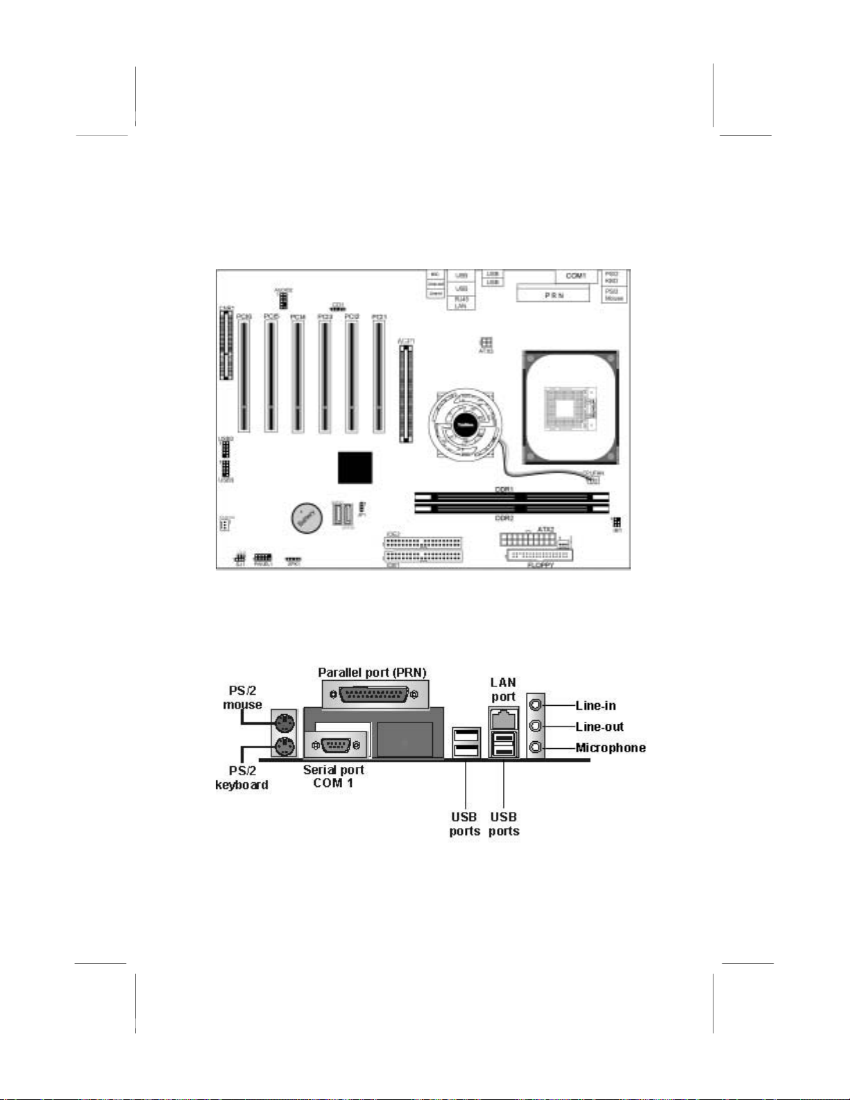
Identify major components on the mainboard via this diagram
underneath.
I/O Ports
The illustration below shows a side view of the built-in I/O ports
on the mainboard.
tional
8
Page 25
1
PS/2 Mouse
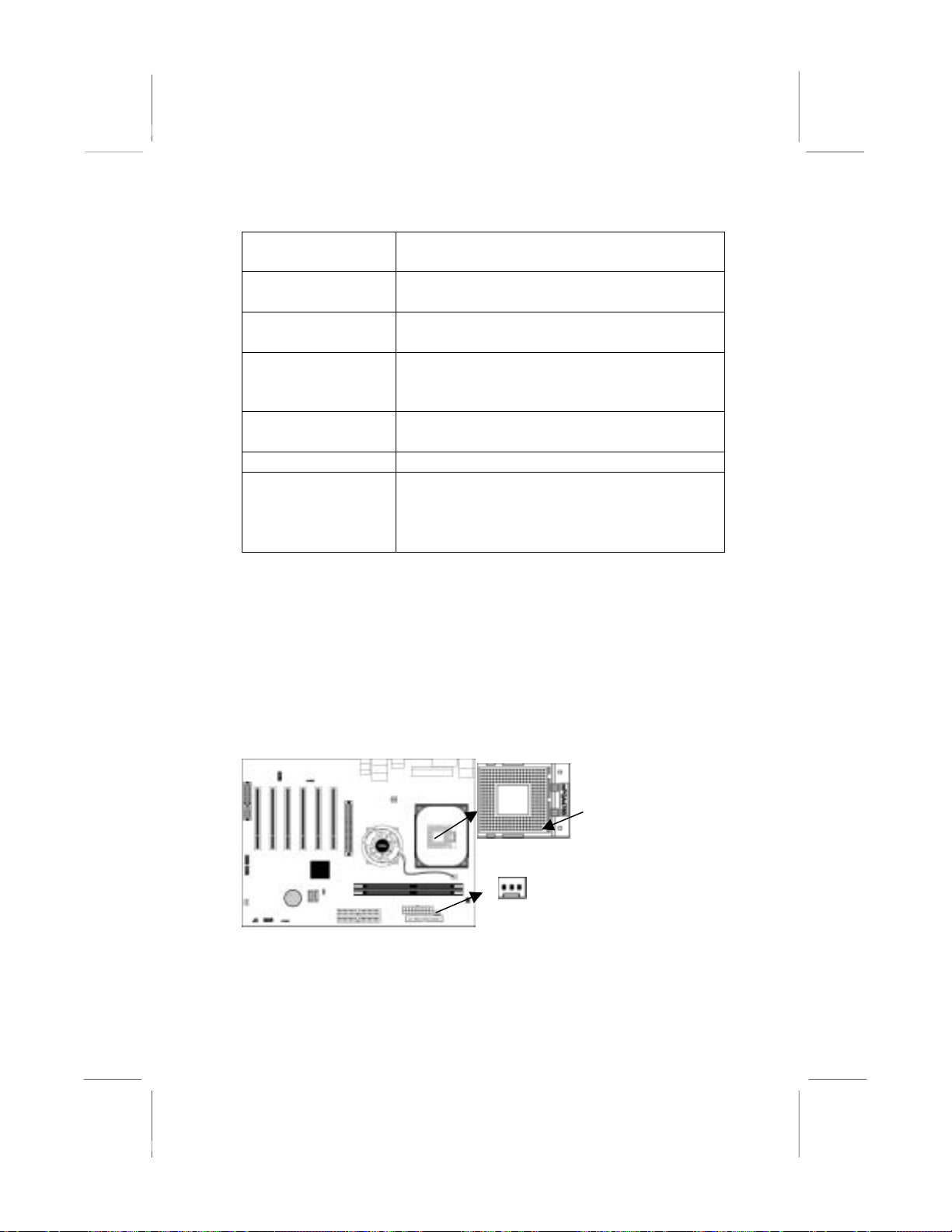
Use the upper PS/2 port to connect a PS/2
pointing device.
PS/2 Keyboard
Use the lower PS/2 port to connect a PS/2
keyboard.
Parallel Port
(PRN)
COM1
Use the Parallel port to connect printers or
other parallel communications devices.
Use the COM port to connect serial devices
such as mice or fax/modems. COM1 is
identified by the system as COM1.
LAN Port
(optional)
USB Ports
Audio Ports
Connect an RJ-45 jack to the LAN port to
connect your computer to the Network.
Use the USB ports to connect USB devices.
Use the three audio ports to connect audio
devices. The first jack is for stereo Line-In
signal. The second jack is for stereo LineOut signal. The third jack is for Microphone.
Installing the Processor
This mainboard has a Socket 478 processor socket. When choosing
a processor, consider the performance requirements of the system.
Performance is based on the processor design, the clock speed and
system bus frequency of the processor, and the quantity of internal
cache memory and external cache memory.
CPU Installation Procedure
Follow these instructions to install the CPU:
Pin 1
SOCKET-478
CPUFAN
1. Unhook the locking lever of the CPU socket. Pull
the locking lever away from the socket and raising
it to the upright position.
9
Page 26
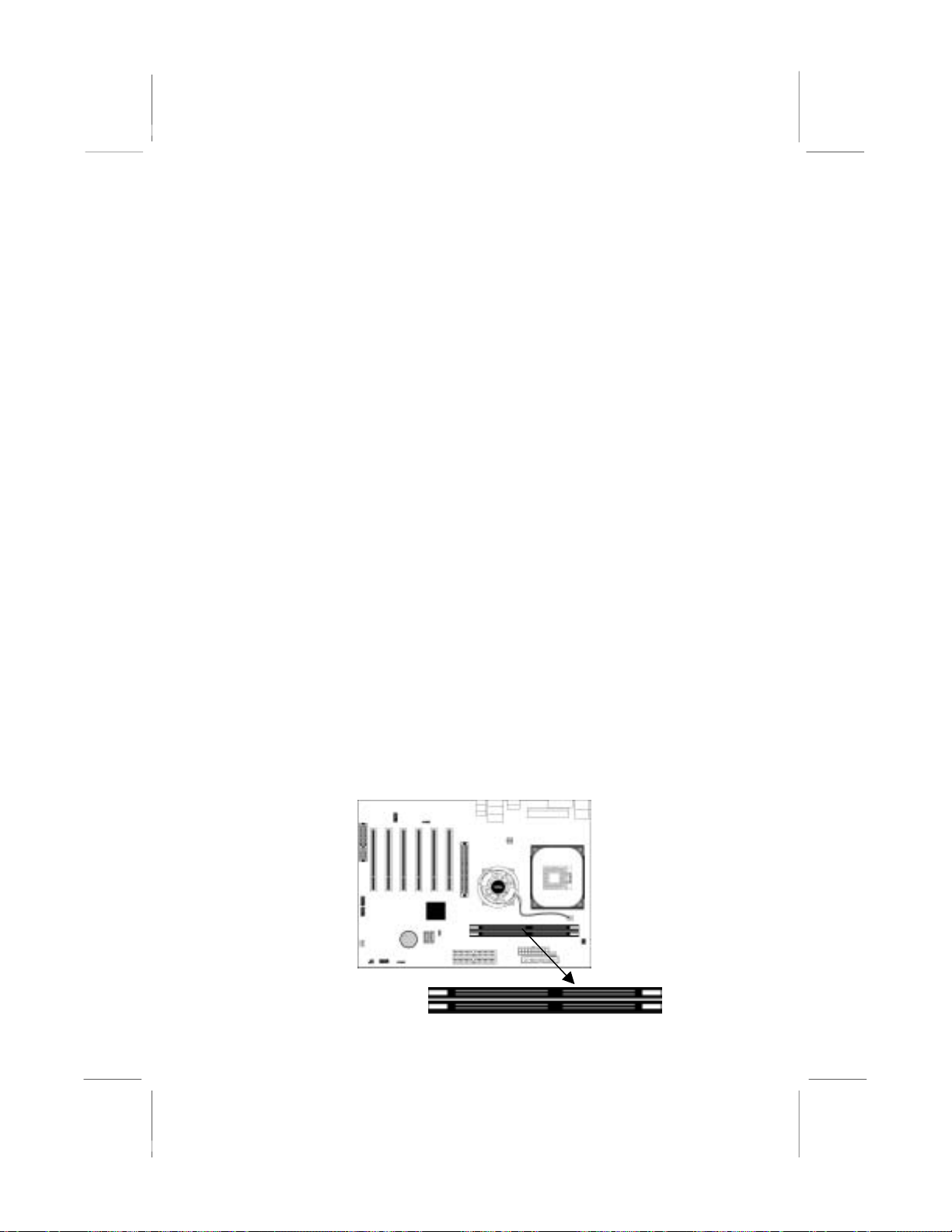
2. Match the pin1 corner marked as the beveled edge
on the CPU with the pin1 corner on the socket.
Insert the CPU into the socket. Do not use force.
3. Push the locking lever down and hook it under the
latch on the edge of socket.
4. Apply thermal grease to the top of the CPU.
5. Install the cooling fan/heatsink unit onto the CPU,
and secure them all onto the socket base.
6. Plug the CPU fan power cable into the CPU fan
connector (CPUFAN) on the mainboard.
Installing Memory Modules
This mainboard accommodates two 184-pin 2.5V unbuffered
Double Data Rate SDRAM (DDR SDRAM) Dual Inline
Memory Module (DIMM) sockets, and supports up to 2.0 GB
of 400 MHz DDR SDRAM.
DDR SDRAM is a type of SDRAM that supports data transfers on
both edges of each clock cycle (the rising and falling edges),
effectively doubling the memory chip’s data throughput. DDR
DIMMs can synchronously work with 100 MHz or 133 MHz
memory bus.
DDR SDRAM provides 1.6 GB/s, 2.1 GB/s or 3.2 GB/s data
transfer rate when the bus is 100 MHz, 133 MHz or 200 MHz
respectively. DDR SDRAM uses additional power and ground
lines and requires 184-pin 2.5V unbuffered DIMM module.
DIMM1
DIMM2
10
Page 27
Memory Module Installation Procedure
These modules can be installed with up to 2 GB system memory.
Refer to the following to install the memory module.
1. Push down the latches on both sides of the DIMM
socket.
2. Align the memory module with the socket. There is
a notch on the DIMM socket that you can install the
DIMM module in the correct direction. Match the
cutout on the DIMM module with the notch on the
DIMM socket.
3. Install the DIMM module into the socket and press
it firmly down until it is seated correctly. The
socket latches are levered upwards and latch on to
the edges of the DIMM.
4. Install any remaining DIMM modules.
Jumper Settings
Connecting two pins with a jumper cap is SHORT; removing a
jumper cap from these pins, OPEN.
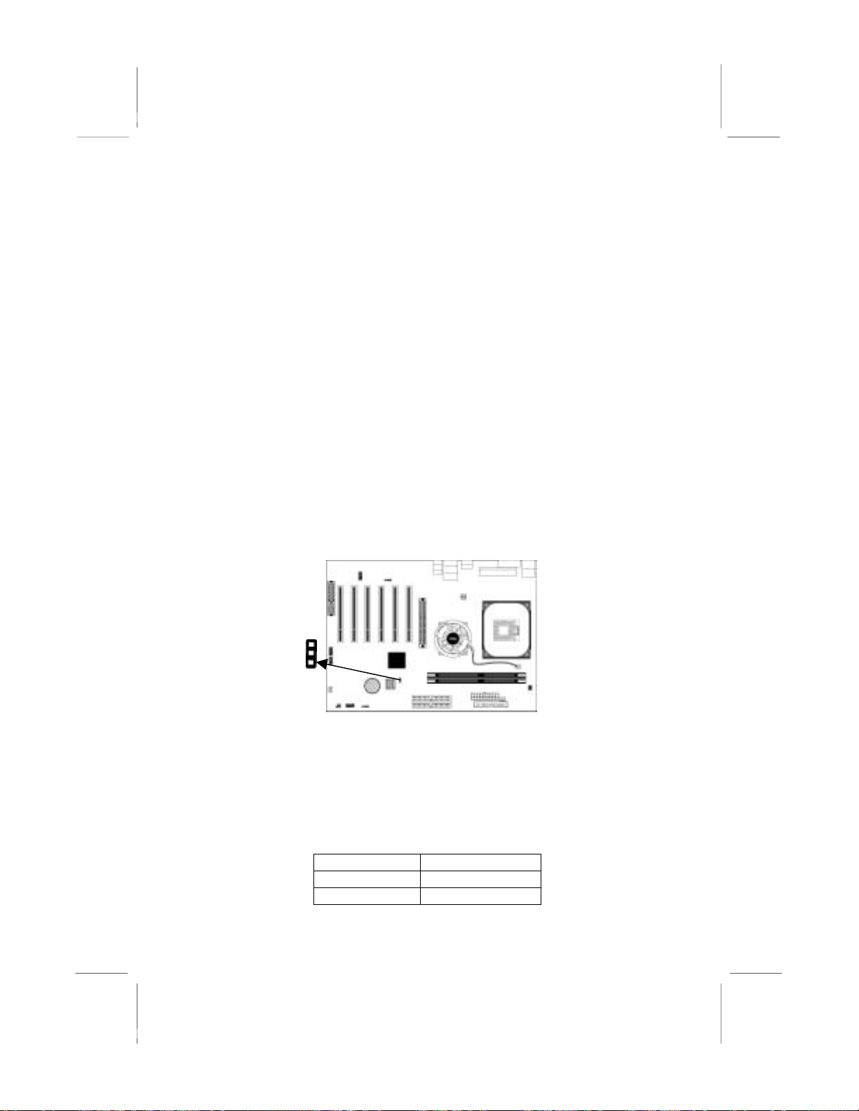
1
JP1
JP1: Clear CMOS Jumper
Use this jumper to clear the contents of the CMOS memory. You
may need to clear the CMOS memory if the settings in the Setup
Utility are incorrect and prevent your mainboard from operating.
To clear the CMOS memory, disconnect all the power cables from
the mainboard and then move the jumper cap into the CLEAR
setting for a few seconds.
Function Jumper Setting
Normal Short Pins 1-2
Clear CMOS Short Pins 2-3
11
Page 28
Install the Mainboard
ATX3
ATX2
1
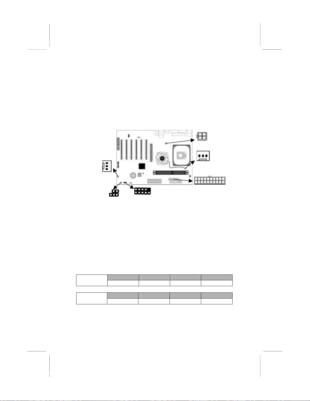
Install the mainboard in a system chassis (case). The board is an
ATX size mainboard. You can install this mainboard in an ATX
case. Make sure your case has an I/O cover plate matching the
ports on this mainboard.
Install the mainboard in a case. Follow the case manufacturer’s
instructions to use the hardware and internal mounting points on
the chassis.
1
1
SYSTEMFAN
PWRFAN
Connect the power connector from the power supply to the ATX2
connector on the mainboard. ATX3 is the CPU Vcore power
connector.
If there is a cooling fan installed in the system chassis, connect the
cable from the cooling fan to the SYSFAN fan power connector on
the mainboard.
Connect the power cooling fan cable to PWRFAN connector.
Connect the case LED cables to the optional Single color LED
connectors LSJ1 and SJ1.
ACPI LED function:
(1,2)
(1,3) (2,3)
LSJ1
1
SJ1
S0 S1 S3 S4/S5 LSJ1
Dark Dark Light Dark
S0 S1 S3 S4/S5 SJ1
Light Blinking Blinking Dark
12
Page 29
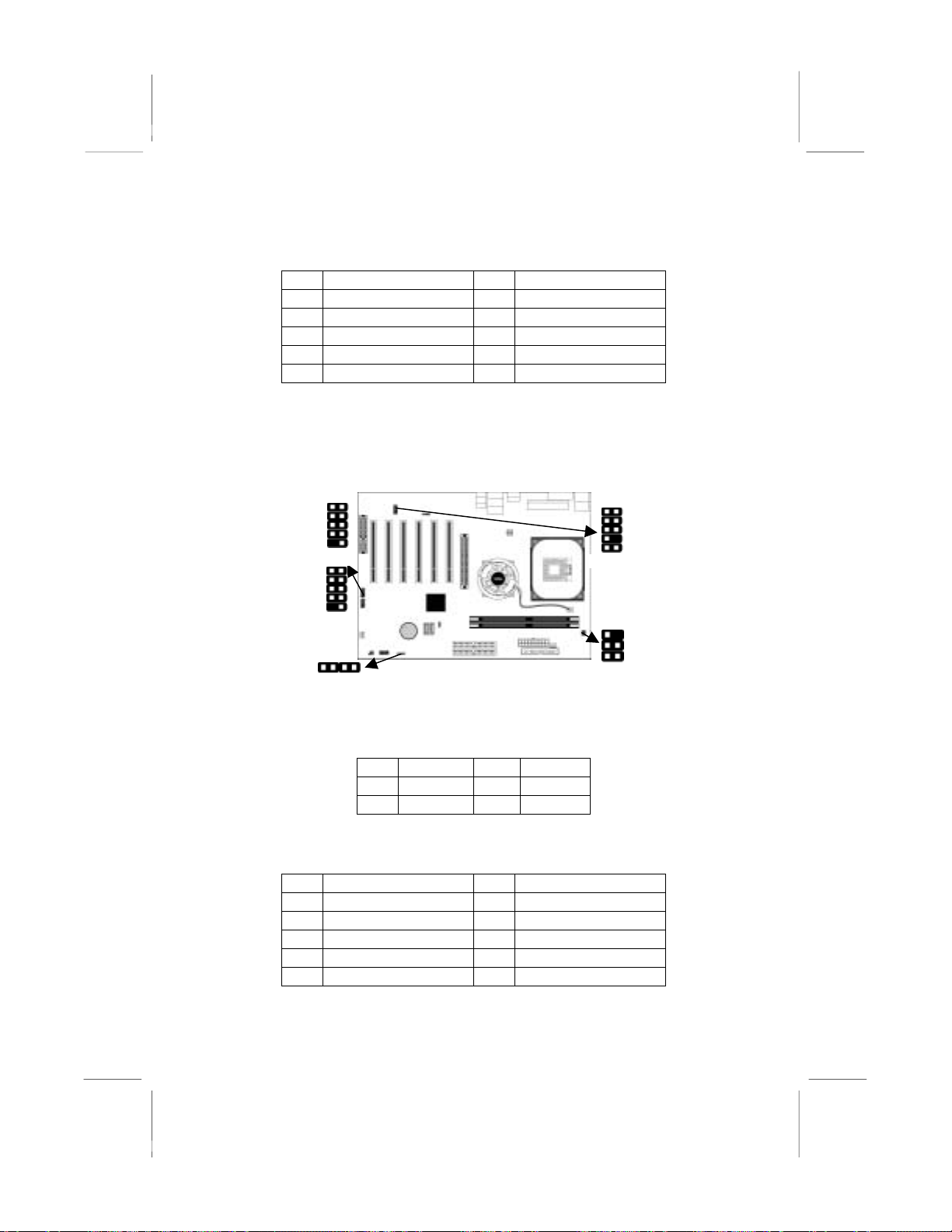
Connect the case switches and indicator LEDs to the PANEL1
A
connector. Here is a list of the PANEL1 pin assignments.
Pin Signal Pin Signal
1 HD_LED_P 2 FP PWR/SLP
3 HD_LED_N 4 FP PWR/SLP
5 RESET_SW_N 6 POWER_SW_P
7 RESET_SW_P 8 POWER_SW_N
9 RSVD_DNU 10 KEY
Connecting Optional Devices
Refer to the following for information on connecting the
mainboard’s optional devices:
1
1
USB2
1
USB3
1
SPK1
UDIO2
1
IR1
SPK1: Speaker Connector
Connect the cable from the PC speaker to the SPK1 connector on
the mainboard.
Pin Signal Pin Signal
1 SPKR 2 NC
3 GND 4 +5V
AUDIO2: Front Panel Audio Connector
This connector allows the user to install auxiliary front-oriented
microphone and line-out ports for easier access.
Pin Signal Pin Signal
1 AUD_MIC 2 AUD_GND
3 AUD_MIC_BIAS 4 AUD_VCC
5 AUD_FPOUT_R 6 AUD_RET_R
7 HP_ON 8 KEY
9 AUD_FPOUT_L 10 AUD_RET_L
13
Page 30
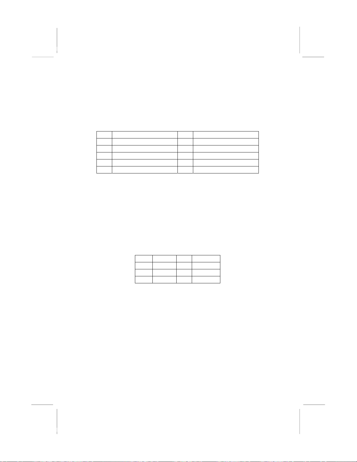
USB2/USB3: Front panel USB Connector
The mainboard has USB ports installed on the rear edge I/O port
array. Additionally, some computer cases have USB ports at the
front of the case. If you have this kind of case, use auxiliary USB
connectors USB2/USB3 to connect the front-mounted ports to the
mainboard.
Pin Signal Pin Signal
1 VERG_FP_USBPWR0 2 VERG_FP_USBPWR0
3 USB_FP_P0- 4 USB_FP_P15 USB_FP_P0+ 6 USB_FP_P1+
7 GROUND 8 GROUND
9 KEY 10 USB_FP_OC0
1. Locate the USB2/3 connector on the mainboard.
2. Plug the bracket cable onto the USB2/3 connector.
3. Remove a slot cover from one of the expansion slots on the
system chassis. Install an extension bracket in the opening.
Secure the extension bracket to the chassis with a screw.
IR1: Infrared Port
The infrared port allows the wireless exchange of information
between your computer and similarly equipped devices such as
printers, laptops, Personal Digital Assistants (PDAs), and other
computers.
Pin Signal Pin Signal
1 NC 2 KEY
3 +5V 4 GND
5 IRTX 6 IRRX
1. Locate the infrared port IR1 connector on the mainboard.
2. If you are adding an infrared port, connect the ribbon cable
from the port to the IR1 connector and then secure the port to
an appropriate place in your system chassis.
14
Page 31
Install Other Devices
Install and connect any other devices in the system following the
steps below.
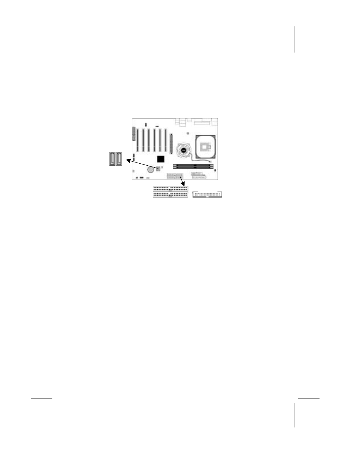
SATA1
SATA2
IDE2
1
1
IDE1
FLOPPY
1
Floppy Disk Drive
The mainboard ships with a floppy disk drive cable that can
support one or two drives. Drives can be 3.5” or 5.25” wide, with
capacities of 360K, 720K, 1.2MB, 1.44MB, or 2.88MB.
Install your drives and connect power from the system power
supply. Use the cable provided to connect the drives to the floppy
disk drive connector FLOPPY.
IDE Devices
IDE devices include hard disk drives, high-density diskette drives,
and CD-ROM or DVD-ROM drives, among others.
The mainboard ships with an IDE cable that can support one or two
IDE devices. If you connect two devices to a single cable, you
must configure one of the drives as Master and one of the drives as
Slave. The documentation of the IDE device will tell you how to
configure the device as a Master or Slave device. The Master
device connects to the end of the cable.
Install the device(s) and connect power from the system power
supply. Use the cable provided to connect the device(s) to the
Primary IDE channel connector IDE1 on the mainboard.
15
Page 32
If you want to install more IDE devices, you can purchase a second
IDE cable and connect one or two devices to the Secondary IDE
channel connector IDE2 on the mainboard. If you have two
devices on the cable, one must be Master and one must be Slave.
Serial ATA Devices
The Serial A T A (Advanced Technology Attachment) is the
standard interface for the IDE hard drives, which is designed to
overcome the design limitations while enabling the storage
interface to scale with the growing media rate demands of PC
platforms. It provides you a faster transfer rate of 150 Mbytes/
second. If you have installed a Serial ATA hard drive, you can
connect the Serial ATA cables to the Serial ATA hard drive or the
connecter on the mainboard.
On the mainboard, locate the Serial ATA connectors SATA1/2,
which support new Serial ATA devices for the highest data transfer
rates, simpler disk drive cabling and easier PC assembly.
It eliminates limitations of the current Parallel ATA interface, but
maintains register compatibility and software compatibility with
Parallel A TA.
Internal Sound Connections
If you have installed a CD-ROM drive or DVD-ROM drive, you
can connect the drive audio cable to the onboard sound system.
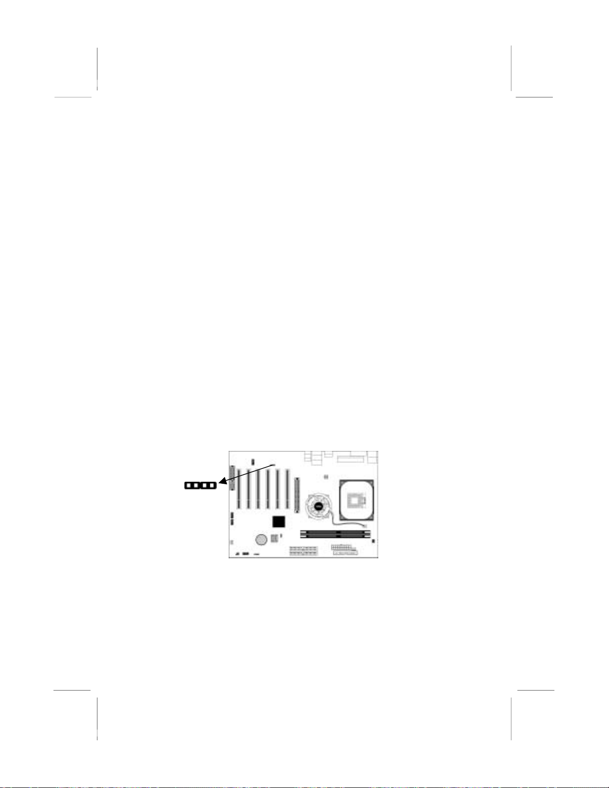
CD1
1
When you first start up your system, the BIOS should
automatically detect your CD-ROM/DVD drive. If it doesn’t, enter
the Setup Utility and configure the CD-ROM/DVD drive that you
have installed. On the mainboard, locate the 4-pin connector CD1.
16
Page 33
Pin Signal
A
1 CD IN L
2 GND
3 GND
4 CD IN R
Expansion Slots
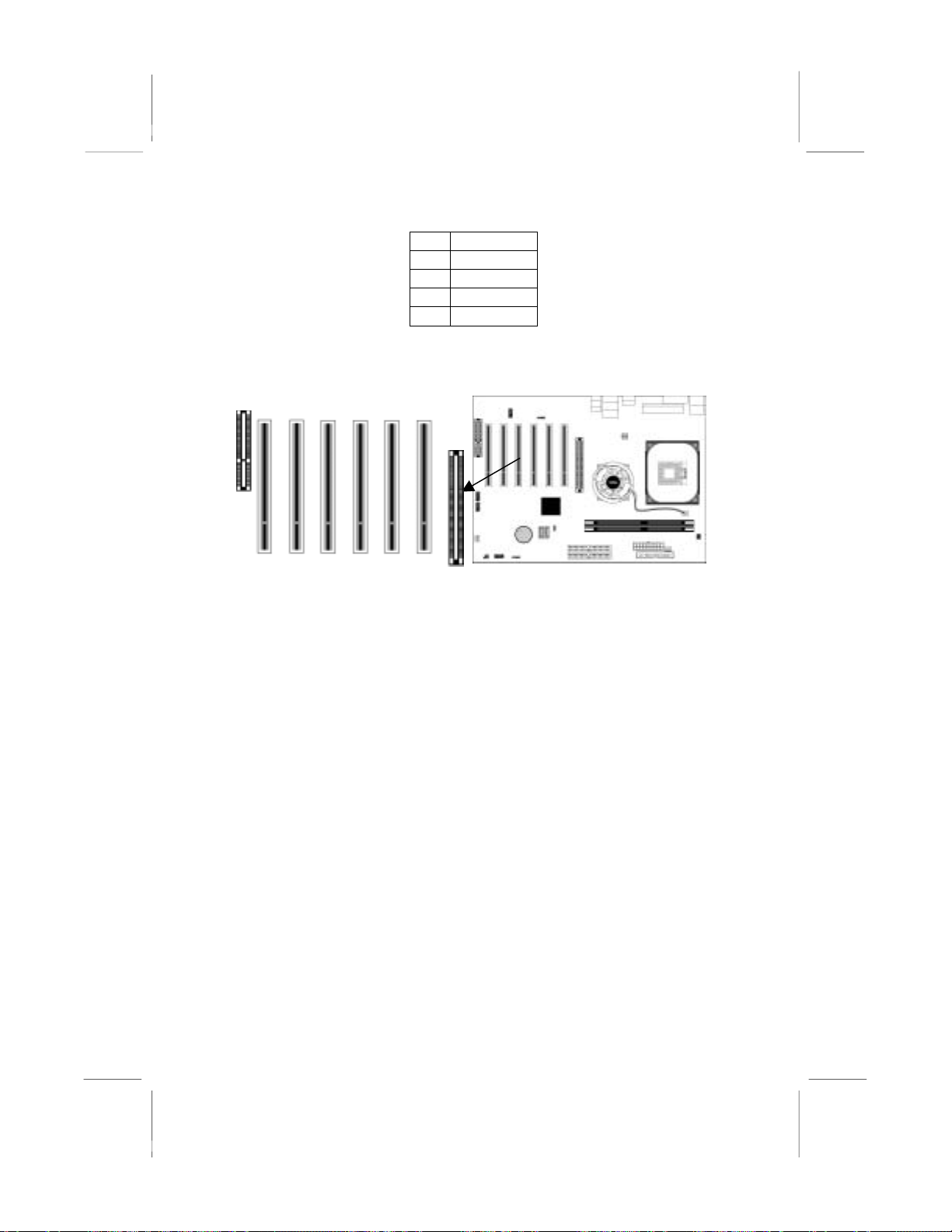
This mainboard has one AGP, one CNR and six 32-bit PCI slots.
CNR1
GP1
PCI6 PCI5 PCI4 PCI3 PCI2 PCI1
Follow the steps below to install an AGP/CNR/PCI expansion card.
1. Locate the AGP, CNR or PCI slots on the mainboard.
2. Remove the blanking plate of the slot from the system chassis.
3. Install the edge connector of the expansion card into the slot.
Ensure the edge connector is correctly seated in the slot.
4. Secure the metal bracket of the card to the system chassis with
a screw.
8x AGP Slot
You can install a graphics adapter that supports the 8x AGP
specification and has a 8x AGP edge connector in the AGP slot.
CNR Slot
You can install the CNR (Communications and Networking Riser)
cards in this slot, including LAN, Modem, and Audio functions.
PCI Slots
You can install the 32-bit PCI interface expansion cards in the slots
(Five Master PCI slots: PCI1~5 and one Slave PCI slot: PCI 6).
17
Page 34

Chapter 3
BIOS Setup Utility
Introduction
The BIOS Setup Utility records settings and information of your
computer, such as date and time, the type of hardware installed,
and various configuration settings. Your computer applies the
information to initialize all the components when booting up and
basic functions of coordination between system components.
If the Setup Utility configuration is incorrect, it may cause the
system to malfunction. It can even stop your computer booting
properly. If it happens, you can use the clear CMOS jumper to
clear the CMOS memory which has stored the configuration
information; or you can hold down the Page Up key while
rebooting your computer. Holding down the Page Up key also
clears the setup information.
You can run the setup utility and manually change the
configuration. You might need to do this to configure some
hardware installed in or connected to the mainboard, such as the
CPU, system memory, disk drives, etc.
Page 35
Running the Setup Utility
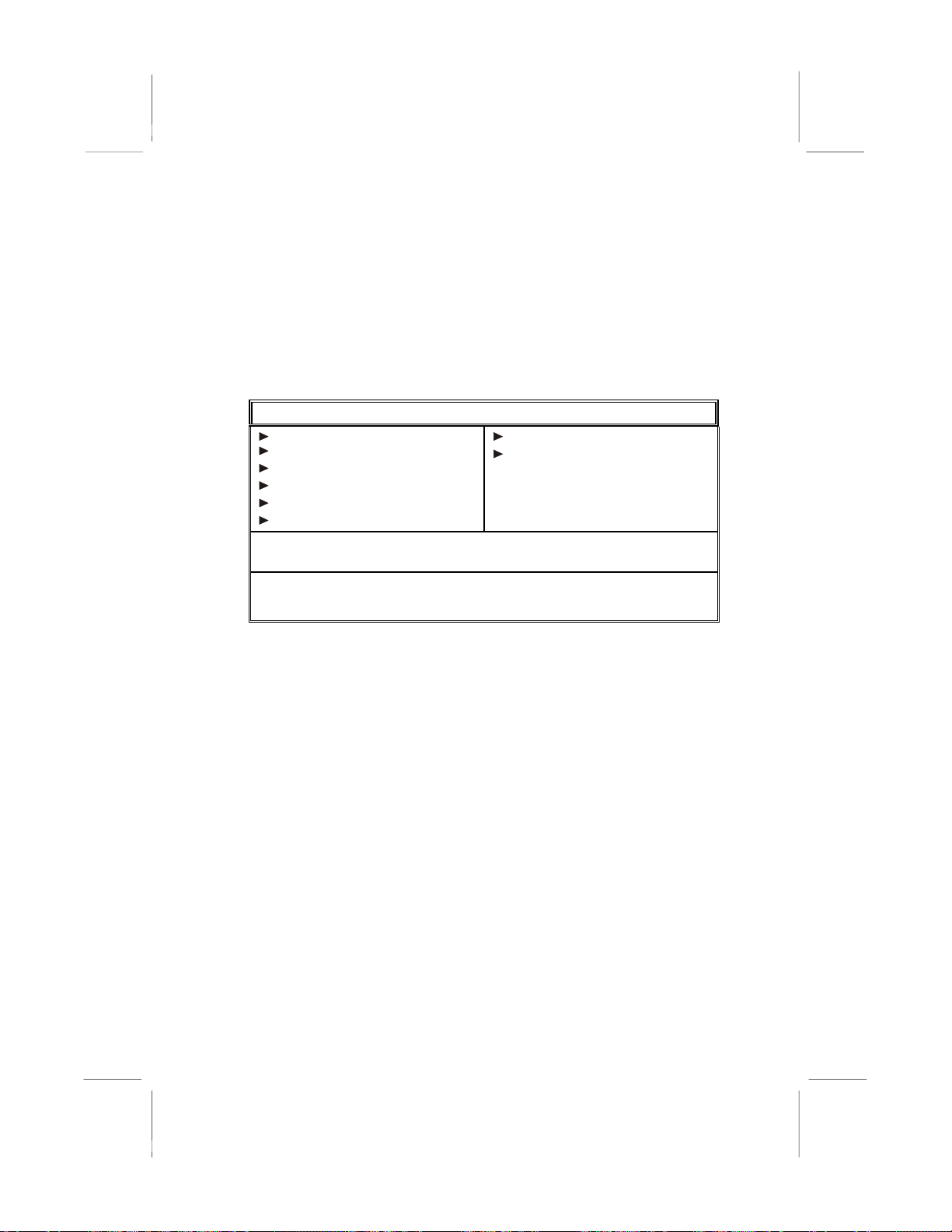
Every time you start your computer, a message appears on the
screen before the operating system loading that prompts you to
“Hit <DEL>if you want to run SETUP”. Whenever you see this
message, press the Delete key, and the Main menu page of the
Setup Utility appears on your monitor.
CMOS SETUP UTILITY – Copyright (C) 1985-2003, American Megatrends, Inc.
Standard CMOS Setup
Advanced Setup
Features Setup
Power Management Setup
PCI / Plug and Play Setup
BIOS Security Features
↑ ↓ ← →: Move Enter: Select +/-/: Value F10: Save Esc: Exit
F1: General Help F9: Optimized Defaults
CPU PnP Setup
Hardware Monitor
Load Optimal Defaults
Save Changes and Exit
Discard Changes and Exit
Standards COMOS setup for changing time, date, hard disk type, etc.
V02.54 (C) 1985-2003, American Megatrends, Inc.
You can use cursor arrow keys to highlight anyone of options on
the main menu page. Press Enter to select the highlighted option.
Press the Escape key to leave the setup utility. Press +/-/ to modify
the selected field’s
values.
Some options on the main menu page lead to tables of items with
installed values that you can use cursor arrow keys to highlight one
item, and press PgUp and PgDn keys to cycle through alternative
values of that item. The other options on the main menu page lead
to dialog boxes requiring your answer Yes or No by hitting the Y
or N keys.
If you have already changed the setup utility, press F10 to save
those changes and exit the utility. Press F1 to display a screen
describing all key functions. Press F9 to install the setup utility
with a set of default values.
19
Page 36
Standard CMOS Setup Page
This page displays a table of items defining basic information
about your system.
CMOS SETUP UTILITY – Copyright (C) 1985-2003, American Megatrends, Inc.
Standard CMOS Setup
System Time: 00:01:38
System Date: Fri 09/19/2003
Primary IDE Master : Not Detected
Primary IDE Slave : Not Detected
Secondary IDE Master : Not Detected
Secondary IDE Slave : Not Detected
Third IDE Master : Not Decteted
Fourth IDE Master : Not Detected
Floppy Drive A : 1.44 MB 3 1/2
Floppy Drive B : Disabled
Help Item
User [Enter], [TAB]
or [SHIFT-TAB] to
select a field.
Use [+] or [-] to
configure system
time.
Date & Time
IDE
Primary Master
Primary Slave
Secondary Master
Secondary Slave
Third Master
Fourth Master
Floppy Drive A
Floppy Drive B
These items set up system date and time.
These items configure devices connected to
the Primary, Secondary, Third and Fourth
IDE channels. To configure an IDE hard
disk drive, choose Auto. If the Auto setting
fails to find a hard disk drive, set it to User,
and then fill in the hard disk characteristics
(Size, Cyls, etc.) manually. If you have a
CD-ROM drive, select the setting CDROM.
If you have an ATAPI device with
removable media (e.g. a ZIP drive or an LS-
120), select Floptical.
These items set up size and capacity of the
floppy diskette drive(s) installed in the
system.
20
Page 37
Advanced Setup Page
This page sets up more advanced information about your system.
Handle this page with caution. Any changes can affect the
operation of your computer.
CMOS SETUP UTILITY – Copyright (C) 1985-2003, American Megatrends, Inc.
Advanced Setup
Quick Boot Enabled
st
Boot Device 1st Floppy Drive
1
nd
Boot Device Network: Realtek R
2
Bootup Num-Lock On
Boot To OS/2 > 64MB No
Graphic Win Size 64MB
Configure DRAM Timing by SPD Enabled
Hyper Threading Function Disabled
Auto Detect DIMM/PCI Clk Enabled
Spread Spectrum Disabled
Vdimm Voltage Control 2.65V
Help Item
Allows BIOS to
skip certain tests
while booting. This
will decrease the
time needed to
boot the system.
Quick Boot
1st Boot Device
nd
2
Boot Device
BootUp NumLock
Boot To OS/2>
64MB
Graphic Win
Size
Configure
DRAM Timing
By SPD
If you enable this item, the system starts
up more quickly be elimination some of
the power on test routines.
Use these items to determine the device
order the computer uses to look for an
operating system to load at start-up time.
This item determines if the Num Lock
key is active or inactive at system startup time.
Enable this item if you are booting the
OS/2 operating system and you have
more than 64MB of system memory
installed.
This item defines the size of aperture if
you use a graphic adapter.
This item allows you to enable or disable
the DRAM timing defined by the Serial
Presence Detect electrical.
21
Page 38
Hyper Threading
Function
If your P4 CPU is not HT CPU, this item
will be hidden.
If your P4 CPU is HT CPU, BIOS will
show this item. You can set "Disabled"
or "Enabled" to control HT CPU support
in O.S. Set “Enabled” to test HT CPU
function.
Auto detect
DIMM/PCI
Clock
Spread Spectrum
When this item is enabled, BIOS will
disable the clock signal of free
DIMM/PCI slots.
If you enable spread spectrum, it can
significantly reduce the EMI (ElectroMagnetic Interference) generated by the
system.
Vdimm Voltage
Control
Use this item to adjust the voltage of the
DIMM memory.
Features Setup Page
This page sets up some parameters for peripheral devices
connected to the system.
CMOS SETUP UTILITY – Copyright (C) 1985-2003, American Megatrends, Inc.
Features Setup
OnBoard Floppy Controller Enabled
Serial Port1 Address 3F8/IRQ4
OnBoard IR Port Disabled
Parallel Port Address Disabled
OnBoard PCI IDE Controller Both
Audio Device Enabled
Ethernet Device Enabled
Modem Device Auto
OnBoard USB Function Enabled
USB Function for DOS Disabled
Help Item
Allows BIOS to
Enable or Disable
Floppy Controller.
OnBoard
Floppy
Use this item to enable or disable the
onboard floppy disk drive interface.
Controller
Serial Port 1
Address
Use this item to enable or disable the
onboard COM1/2 serial port, and to assign
a port address.
22
Page 39
OnBoard IR
Port
Use this item to enable or disable the
onboard infrared port, and to assign a port
address.
Parallel Port
Address
Use this item to enable or disable the
onboard Parallel port, and to assign a port
address.
OnBoard PCI
IDE
Controller
Audio Device
Use this item to enable or disable either or
both of the onboard Primary and Secondary
IDE channels.
This item enables or disables the AC’97
audio chip.
Ethernet
Device
Modem Device
This item enables or disables the onboard
Ethernet LAN.
This item enables or disables the AC’97
modem chip.
OnBoard USB
Function
USB Function
For DOS
Enable this item if you plan to use the USB
ports on this mainboard.
Enable this item if you plan to use the USB
ports on this mainboard in a DOS
environment.
Power Management Setup Page
This page sets some parameters for system power management
operation.
CMOS SETUP UTILITY – Copyright (C) 1985-2003, American Megatrends, Inc.
Power Management Setup
ACPI Aware O/S Yes
Power Management/APM Enabled
Suspend Mode S1
Suspend Time Out Disabled
Resume On RTC Alarm Disabled
LAN/Ring Power On Disabled
Keyboard Power On Disabled
Help Item
Yes / No
ACPI support for
Operating System.
Yes: If OS
supports ACPI.
No: If OS does not
support ACPI.
23
Page 40

ACPI Aware
O/S
Power
Management
Suspend Mode
Suspend Time
Out
Resume On
RTC Alarm
LAN/Ring
Power On
Keyboard
Power On
This item supports ACPI (Advanced
Configuration and Power management
Interface). Use this item to enable or disable
the ACPI feature.
Use this item to enable or disable a power
management scheme. If you enable power
management, you can use the items below
to set the power management operation.
Both APM and ACPI are supported.
This item selects the status S1(Stop Clock)
or S3(Suspend to RAM) when the system
enters the power-saving Suspend mode.
This item sets up the timeout for Suspend
mode in minutes. If the time selected passes
without any system activity, the computer
will enter power-saving Suspend mode.
The system can be turned off with a
software command. If you enable this item,
the system can automatically resume at a
fixed time based on the system’s RTC
(realtime clock). Use the items below this
one to set the date and time of the wake-up
alarm. You must use an ATX power supply
in order to use this feature.
Your system can enter the software power
down. If you enable this item, the system
can automatically resume if there is traffic
on the network adapter.
If you enable this item, system can
automatically resume by pressing hot keys
on the keyboard or typing in the password.
You must enable the Keyboard Power On
jumper and use an ATX power supply in
order to use this feature.
24
Page 41
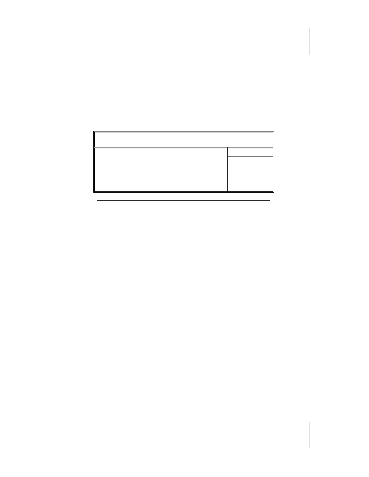
PCI / Plug and Play Setup Page
This page sets up some parameters for devices installed on the PCI
bus and those utilizing the system plug and play capability.
CMOS SETUP UTILITY – Copyright (C) 1985-2003, American Megatrends, Inc.
PCI / Plug and Play Setup
Primary Graphics Adapter AGP
Allocate IRQ to PCI VGA Yes
PCI IDE BusMaster Disabled
Primary
Graphics
Adapter
This item indicates if the primary graphics
adapter uses the PCI or the AGP bus. The
default AGP setting still lets the onboard
display work and allows the use of a second
display card installed in an AGP slot.
Allocate IRQ
to PCI VGA
If this item is enabled, an IRQ will be
assigned to the PCI VGA graphics system.
You set this value to No to free up an IRQ.
PCI IDE
BusMaster
This item enables or disables the DMA
under DOS mode. We recommend you to
leave this item at the default value.
Help Item
Select which
graphics controller
to use as the
primary boot
device.
25
Page 42
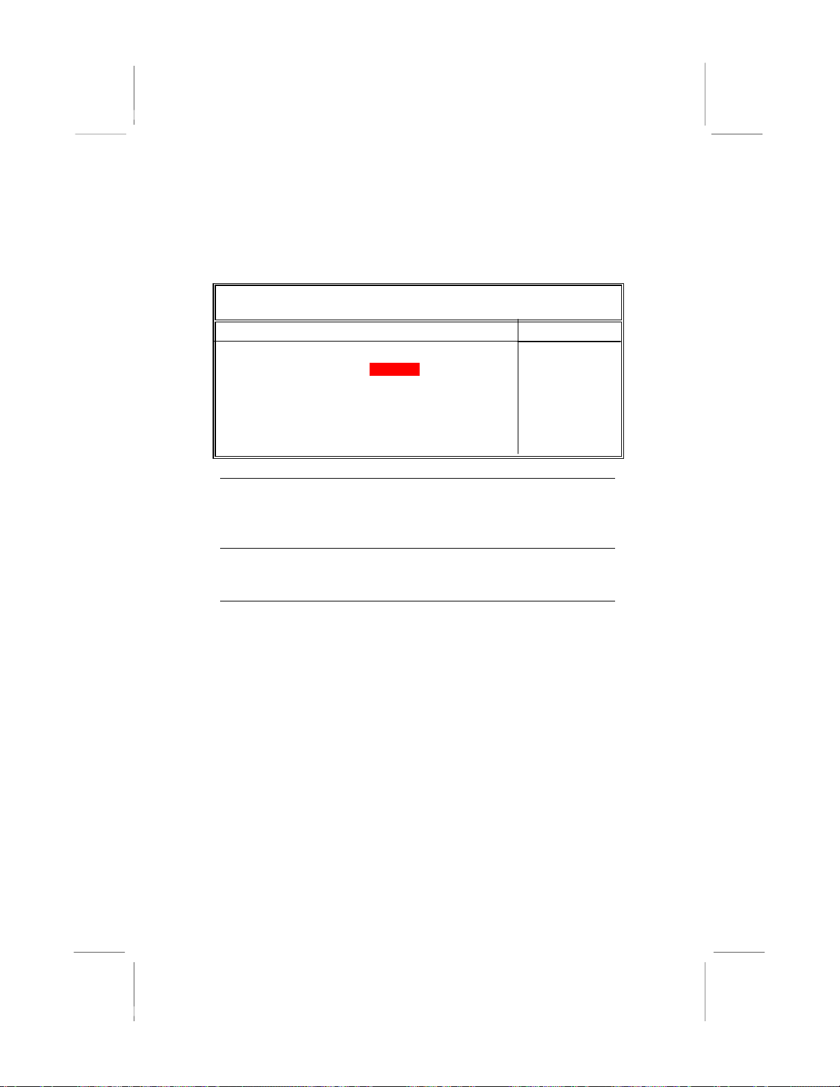
BIOS Security Features Setup Page
This page helps you install or change a password.
CMOS SETUP UTILITY – Copyright (C) 1985-2003, American Megatrends, Inc.
BIOS Security Features Setup
Security Settings
Supervisor Password : Not Installed
Change Supervisor Password Press Enter
Install or Change
the password.
Supervisor
Password
Change
Supervisor
Password
This item indicates whether a supervisor
password has been set. If the password has
been installed, Installed displays. If not, Not
Installed displays.
You can select this option and press <Enter>
to access the sub menu. You can use the sub
menu to change the supervisor password.
Help Item
26
Page 43

CPU PnP Setup Page
This page helps you manually configure the CPU of this
mainboard. The system will automatically detect the type of
installed CPU and make the appropriate adjustments to these items
on this page.
CMOS SETUP UTILITY – Copyright (C) 1985-2003, American Megatrends, Inc.
CPU PnP Setup
Manufacturer : Intel
Ratio Status : Locked
Ratio Actual Value : 18
Ration CMOS Setting : 8
DRAM Frequency Auto
CPU Frequency 133 MHz
CPU Over-clocking Func.: Disabled
Help Item
Sets the ration
between CPU Core
Clock and the FSB
Frequency. Note: If
an invalid ratio is set
in CMOS then actual
and setpoint values
may differ. Ratio of
Zero allows external
Manufacturer/
Ratio Status/
Ratio Actual
Value
Ratio CMOS
Setting
DRAM
Frequency
CPU
Frequency
CPU Overclocking Func./
Freq.
These items show the brand, the Locked/
Unlocked ratio status, and the actual ratio of
the CPU installed in your system.
This item selects the ratio of the CPU
installed in your system.
This item shows the frequency of the DRAM
in your system.
This item shows the frequency of the CPU
installed in your system.
This item decides the CPU over-clocking
function/frequency installed in your system.
If the over-clocking fails, please turn off the
system power. And then, hold the PageUp
key (similar to the Clear CMOS function)
and turn on the power, the BIOS will recover
the safe default.
27
Page 44
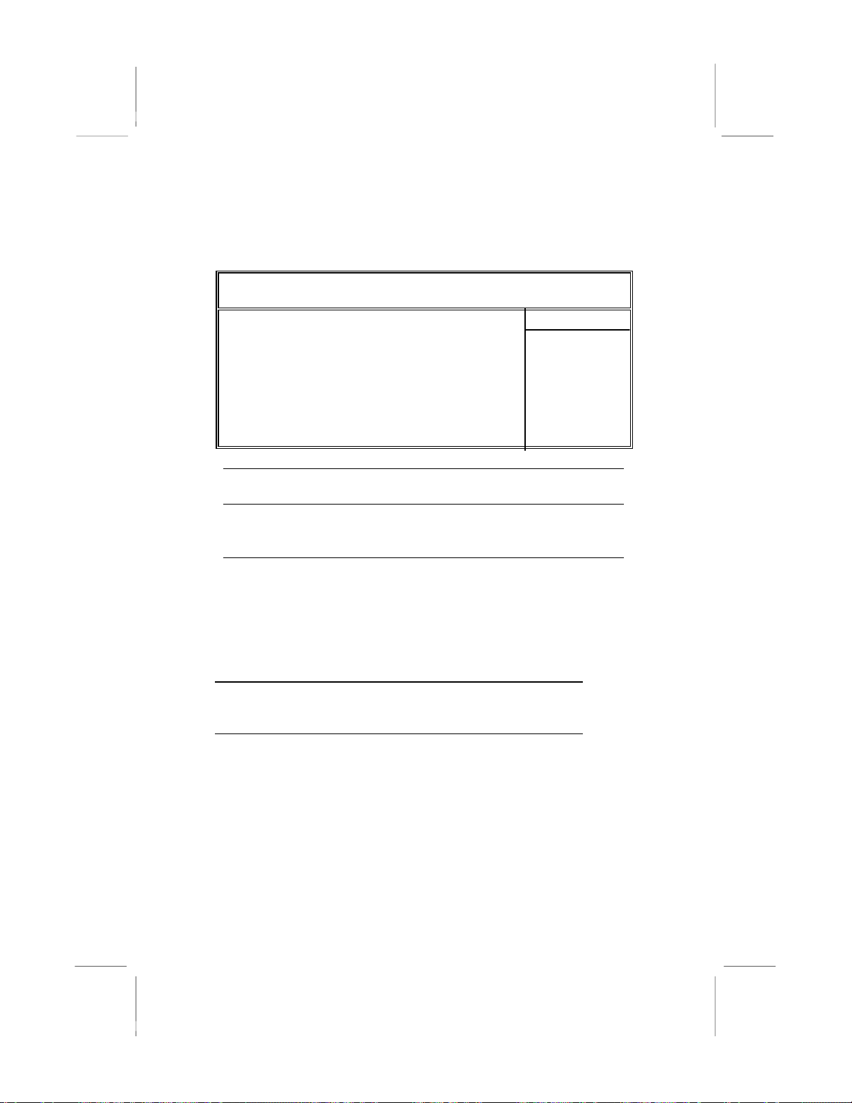
Hardware Monitor Page
This page sets up some parameters for the hardware monitoring
function of this mainboard.
CMOS SETUP UTILITY – Copyright (C) 1985-2003, American Megatrends, Inc.
Hardware Monitor Setup
*** System Hardware Monitor***
Vcore 1.129V
Vdimm 1.564V
Vcc5V 4.985V
SB3V 3.338V
SYSTEM Fan Speed 0 RPM
CPU Fan Speed 4560 RPM
NB Fan Speed 0 RPM
SYSTEM Temperature 33°C/91°F
CPU Temperature 37°C/98°F
Help Item
CPU/NB/System
Temperature
FAN & Voltage
Measurements
These items display CPU, NB and system
temperature measurement.
These items indicate cooling fan speeds in
RPM and the various system voltage
measurements.
Load Optimal Defaults
This option opens a dialog box to ask if you are sure to install
optimi zed defaul t s or not. You press <Y> , and then <E n t e r >, the
Setup Utility loads all default values; or press <N>, and then
<Enter>, the Setup Utility does not load default values.
Note: It is highly recom mend that users enter this option
to load optimal default values for accessing the best
performance.
Save Changes and Exit
Highlight this item and press <Enter> to save the changes that you
have made in the Setup Utility configuration. When the Save
Changes and Exit dialog box appears, press Y to save and exit, or
press N to return to the main menu.
Discard Changes and Exit
Highlight this item and press <Enter> to discard any changes that
28
Page 45

you have made in the Setup Utility and exit the Setup Utility.
When the Discard Changes and Exit dialog box appears, press <Y>
to discard changes and exit, or press <N> to return to the main
menu.
Note: If you have made settings that you do not want to
save, use the "Discard Changes and Exit" item and
press <Y> to discard any changes you have made.
29
Page 46

Chapter 4
Software & Applications
Introduction
This chapter describes the contents of the support CD-ROM that
comes with the mainboard package.
The support CD-ROM contains all useful software, necessary
drivers and utility programs to properly run our products. More
program information is available in a README file, located in the
same directory as the software.
To run the support CD, simply insert the CD into your CD-ROM
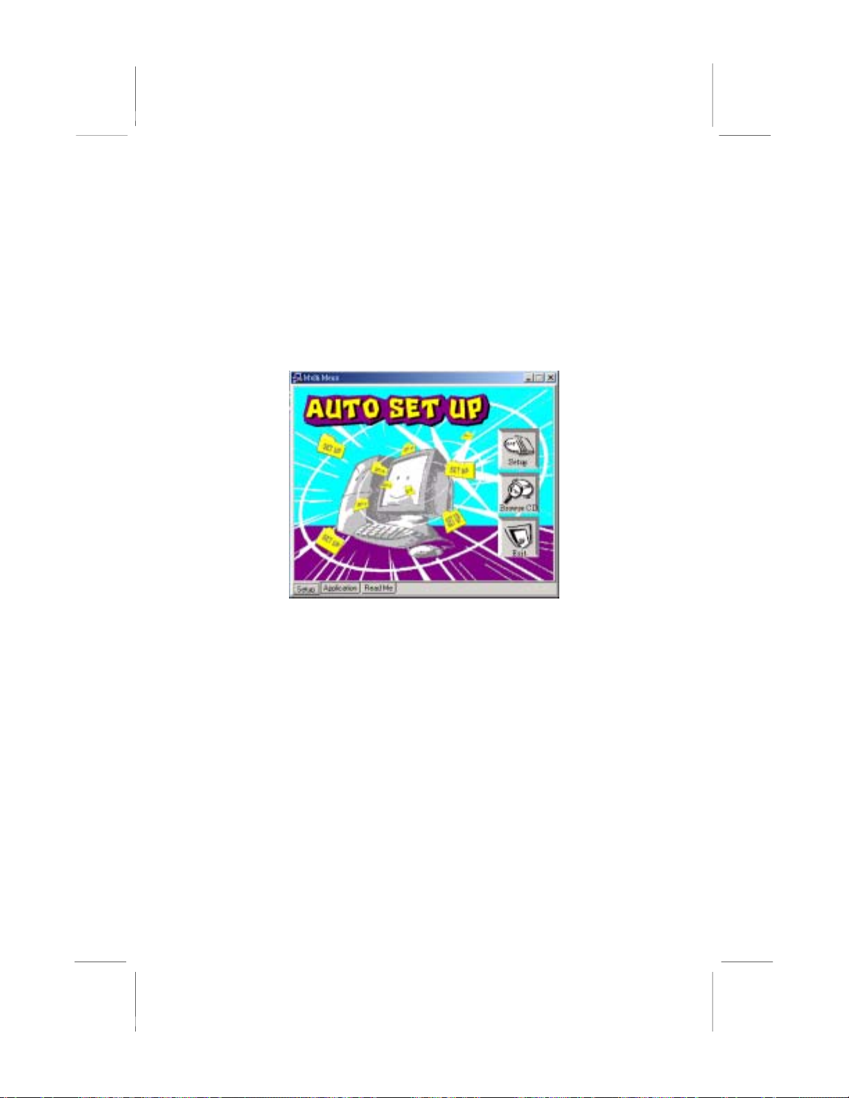
drive. An Auto Setup screen automatically pops out, and then you
can go on the auto-installing or manual installation depending on
your operating system.
If your operating system is Windows 98/ME/2000/XP, it will
automatically install all the drivers and utilities for your mainboard;
if Windows NT or manual installation, please follow the
instructions described as the
Manual Installation
section.
Installing under Windows NT or
30
Page 47
Installing Support Software
1.Insert the support CD-ROM disc in the CD-ROM drive.
2.When you insert the CD-ROM disc in the system CD-ROM
drive, the CD automatically displays an Auto Setup screen.
3.The screen displays three buttons of Setup, Browse CD and Exit
on the right side, and three others Setup, Application and
ReadMe at the bottom. Please see the following illustration.
The Setup button runs the software auto-installing program as
explained in next section.
The Browse CD button is a standard Windows command that you
can check the contents of the disc with the Windows 98 file
browsing interface.
The Exit button closes the Auto Setup window. To run the
program again, reinsert the CD-ROM disc in the drive; or click the
CD-ROM driver from the Windows Explorer, and click the Setup
icon.
The Application button brings up a software menu. It shows the
bundled software that this mainboard supports.
The ReadMe brings you to the Install Path where you can find out
path names of software driver.
31
Page 48
Auto-Installing under Windows 98/ME/2000/XP
If you are under Windows 98/ME/2000/XP, please click the Setup
button to run the software auto-installing program while the Auto
Setup screen pops out after inserting the support CD-ROM:
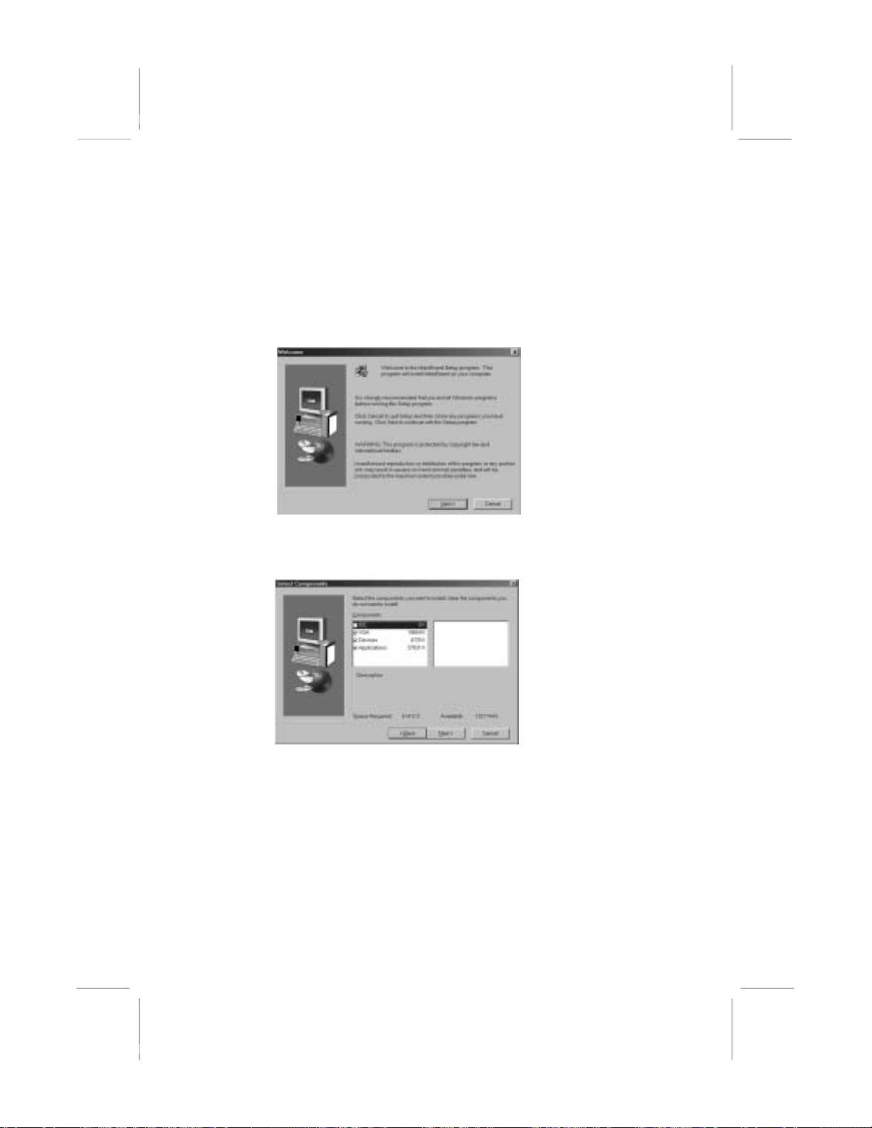
1. The installation program loads and displays the following
screen. Click the Next button.
2. Select the items that you want to setup by clicking on it (the
default options are recommended). Click the Next button to
proceed.
3. The support software will automatically install.
Once any of the installation procedures start, software is
automatically installed in sequence. You need to follow the
onscreen instructions, confirm commands and allow the computer
to restart as few times as needed to complete installing whatever
software you selected. When the process is finished, all the support
software will be installed and start working.
32
Page 49

Installing under Windows NT or Manual Installation
If you are under Windows NT, the auto-installing program doesn’t
work out; or you have to do the manual installation, please follow
this procedure while the Auto Setup screen pops out after inserting
the support CD-ROM:
1. Click the ReadMe to bring up a screen, and then click the
Install Path at the bottom of the screen.
2. Find out your mainboard model name and click on it to obtain
its correct driver directory.
3. Install each software in accordance with the corresponding
driver path.
Bundled Software Installation
All bundled software available on the CD-ROM is for users’
convenience. You can install bundled software as follows:
1. Click the Application button while the Auto Setup screen pops
out after inserting the support CD-ROM.
2. A software menu appears. Click the software you want to install.
3. Follow onscreen instructions to install the software program step
by step until finished.
33
Page 50
Hyper Threading CPU
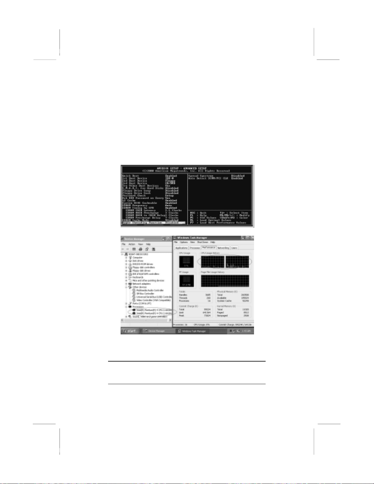
You must update BIOS to initiate BIOS Hyper Threading
Function and use HT CPU function under WinXP Operating
System; if not, please disable this option.
♦ When BIOS detects the HT CPU, it shows the “Hyper
Threading Function (default Disabled)” option, which you must
set Enabled if you want to test HT CPU function. If there is no
HT CPU, this option is hidden and default Disabled.
♦ You must re-install WINXP to activate the HT CPU function.
While you are in Windows Task Manager, please push down
ctrl+Alt Del keys. A dual CPU appears in the CPU Usage
History&Device Manager under WinXP.
Note: Hyper Threading Function only works under
WINXP Operating System; therefore, disable it
under other Operating System.
34
Page 51

Appendix
Intel USB 2.0 Driver Limitations & Manual Installation
♦ USB2.0 Driver only supports the Operating System
WinXP/Win2K, and WinME & Win98SE driver only
supports USB 1.1 function.
Note: If your Operating System Windows XP has the
Service Pack, you can directly access the driver
regardless of the driver limitation.
♦You must follow these steps to manually install the WinXP
driver; otherwise, you can’t succeed this driver’s installation.
1.Simply install Windows XP with PS2 Keyboard/Mouse.
2.Install INF Update 4.00.1009 PV.
• Install IAA 2.1 PV (2124).
• Install GFX 11.0 PC 1.01 (3051).
• Install LAN 6.1 PV.
• Install AC97 Beta.
3.Install USB 2.0 for XP 3616.
4.Use Tools/Folder Options…/View. to change the items
below:
• Enable “Display the full path in the title bar”.
• Enable “Show Hidden files and folders”.
• Disable “Hide extensions of known files types”.
• Disable “Hide protected operating system files
(Recommended)”.
5.Check USB driver version from:
C:\Windows\System32\Drivers directory
USBEHCI.SYS – 3/20/2002.
USBPORT.SYS – 8/17/2001.
USBHUB.SYS – 8/17/2001.
35
Page 52

6.Go on executing the manual installation as below:
6-1 Disable Windows File Protection (WFP)
From Start button/run/Regedit.
Set HKEY_LOCAL_MACHINE\
Software\Microsoft\Windows NT\
CurrentVersion\Winlogon\SFCDisable = 1
6-2 Copy all USB files from CD to HDD.
Copy all test drivers to %windir%\driver
cache\i386.
Copy all test drivers to
%windir%\system32\dllcache
You need to copy file to this directory first.
Otherwise, Windows XP will replace file from this
directory to system32\drivers.
Copy all test drivers to
%windir%\system32\drivers.
6-3 Check USB driver version again.
USBEHCI.SYS – 3/20/2002.
USBPORT.SYS – 3/20/2001.
USBHUB.SYS – 3/20/2001.
6-4 Enable Windows File Protection (WFP)
Start button/run/Regedit.
Set HKEY_LOCAL_MACHINE\
Software\Microsoft\Windows NT\
CurrentVersion\Winlogon\SFCDisable = 0
♦ While installing the USB2.0 driver under WinME operating
system, a green question mark pops out. Please rest assured it is
normal.
♦ Under the Window operating system, the BIOS Setup Utility
doesn’t support the “USB Function For Dos Enable” feature.
♦ You can’t use the USB Keyboard Chicony KU-8933.
36
 Loading...