

Page 1
HSD
MECHATRONIC
DIVISION
Instruction Manual
H5803H0005_EN
Rev. 03
06/2008
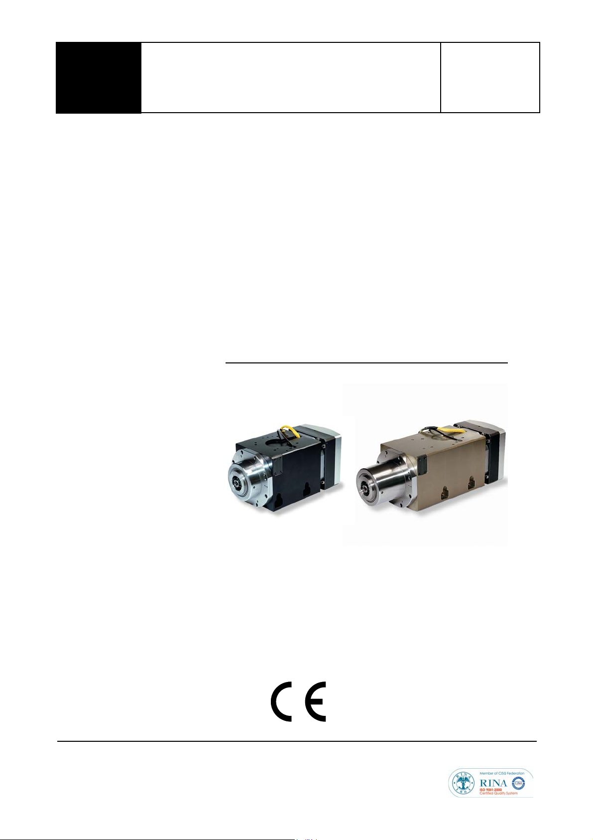
ES779 - ES789
HSD S.p.A.
Head Office
Via della Meccanica, 16
61100 Pesaro (PU) Italy
Tel. +39 0721 439638
Fax +39 0721 441608
Tax Code No. 02196600965
VAT No. IT 01376450415
Customer Service
Via della Meccanica, 16
61100 Pesaro (PU) Italy
Loc. Chiusa di Ginestreto
Tel. +39 0721 439638
Fax +39 0721 441608
E-mail: [email protected]
Web: www.hsd.it
Page 2

Information on the publication
Document code Revision Approval Date of issue
H5803H0005 03 UTE 011 / 02 07 / 2008
List of Updates
Revision Modified
sections
00 of 06 / 2002 --- First edition
01 of 09 / 2005 --- General Revision
02 of 11 / 2007 Cover
§ 3.1.4, 3.1.5
§ 4.2
§ 4.2.8
§ 4.6
§ 4.9, 4.10
§ 6.4
§ 8.1
§ 8.2
§ 8.3.11
§ 8.3.12, 8.3.13
§ 11
03 of 07 / 2008 §4.6.1 Updated air specifications section
Description of modifications
Updated images
ES775 removed, out of production
Views with new bore positions updated
Equivalent electric networks added
Technical card and electric network equivalent to 13.5 kW model added
Missing pneumatic connections added
Electrical connections with HSD mounting plate and MIL connectors
added
Clamping force of A/E 63 hooks added
Shaft kit replacement: procedure and notes about spare parts
Procedure for encoder reader replacement added
Gauges to adjust A/E 63 added
Adjustment procedure S1 and S4 with kit updated
Spare part list updated
This publication is the English translation of the original Italian version of the manual HSD
H5803H0005.
In case of discrepancies between this translation and the original version, refer to the original
version in Italian.
The updated version of this manual is available at HSD website or at the HSD Customer Service
(see page 111).
Manual prepared by the HSD Documentation Department with FrameMaker 7.0
Page 3

HSD
Index
Index
1 Preliminary Information ............................................................................7
1.1 Documents supplied with the product ....................................................... 7
1.2 Purpose of the manual .............................................................................. 7
1.3 Symbols used in the manual .................................................................. 7
1.4 Risks associated with the use of the product ............................................ 8
1.4.1 Risks associated with incorrect use and/or operation ............................ 8
1.4.2 Specific risks during product maintenance ............................................ 9
1.4.3 Residual risks ......................................................................................... 9
1.5 Information on the product ........................................................................ 9
1.5.1 Purpose of the product ........................................................................... 9
1.5.2 Range of applications ............................................................................. 9
1.5.3 EC marking and identification of the product .......................................... 9
1.6 Glossary ................................................................................................. 10
1.7 Warranty ................................................................................................. 11
2 Transport, packaging, unpacking, storage ...........................................12
2.1 Warnings ................................................................................................. 12
2.2 Dimensions and weights ......................................................................... 12
2.3 Transport and Packaging Conditions ...................................................... 12
2.4 Unpacking Procedure ............................................................................. 13
2.5 Storage ................................................................................................... 13
3 Technical specifications ........................................................................14
3.1 Main parts ............................................................................................... 15
3.1.1 ES779 non connectorised, with fixing bores ...................................... 15
3.1.2 ES779 non connectorised, with fixing grooves ................................... 16
3.1.3 ES789 non connectorised, with fixing bores ...................................... 17
3.1.4 ES789 non connectorised, with fixing grooves ................................... 18
3.1.5 ES779 Collet, non connectorised ....................................................... 19
3.1.6 Variations for versions with electrical connectors of HSD type ........... 20
3.1.7 Variations for versions with MIL standard electrical connectors ......... 21
3.1.8 ES789 variations with distributor .......................................................... 22
3.1.9 Variations with floating piston or fixed piston ........................................ 23
3.2 Characteristics and performance ............................................................ 24
3.2.1 ES779 12kW with 500Hz (15,000 rpm) rated frequency ..................... 24
3.2.2 ES779 12kW DP with 250Hz (7,500 rpm) rated frequency ................. 26
3.2.3 ES779 13kW with 500Hz (15,000 rpm) rated frequency .................... 28
3.2.4 ES779 13.5kW with 400Hz (12,000 rpm) rated frequency ................... 30
3.2.5 ES789 18kW with 267Hz (8,000 rpm) rated frequency ....................... 32
3.2.6 ES789 18kW DP with 300Hz (9,000 rpm) rated frequency ................. 34
3.2.7 ES789 17kW with 400Hz (12,000 rpm) rated frequency .................... 36
3.2.8 ES789 13.5kW with 350Hz (10,500 rpm) rated frequency ................. 38
5803H0005_Rev02_enTOC.fm
HSD S.p.A.
3
Page 4

HSD
Index
4 Installation and commissioning.............................................................40
4.1 Dimensional drawings ............................................................................. 40
4.2 Preliminary checks before installation .................................................... 40
4.3 Preparation of the auxiliary systems of the plant .................................... 40
4.4 Mechanical connections ......................................................................... 41
4.4.1 Resting surface ................................................................................... 41
4.4.2 Tool change system ............................................................................ 41
4.4.3 Fastening of models with “fixing bores” ................................................ 41
4.4.4 Fastening of models with “fixing grooves” ............................................ 41
4.4.5 “Collet” model fastening ....................................................................... 42
4.4.6 Threaded service bores ........................................................................ 42
4.5 Fluids distributor .................................................................................... 42
4.6 Pneumatic connections ........................................................................... 43
4.6.1 Specifications for compressed air to be supplied to HSD products ...... 43
4.6.2 Automatic cleaning of the tool holder cone .......................................... 46
4.6.3 Internal pressurisation .......................................................................... 46
4.7 Hydraulic connections and specifications of the cooler ......................... 47
4.7.1 Specifications of the cooler ................................................................... 47
4.7.2 Hydraulic connection points .................................................................. 47
4.8 Pneumatic/hydraulic connections of models with distributor .................. 50
4.9 Electrical connections of models with free cables .................................. 51
4.9.1 ES779 and ES789 Power Cables ........................................................ 51
4.9.2 Sensor Cables (all motors) ................................................................. 52
4.9.3 Encoder cables (Optional) ................................................................... 52
4.10 Electrical connections of models with HSD connectors .......................... 53
4.10.1 Power connector diagram .................................................................... 53
4.10.2 Signal connector diagram ..................................................................... 54
4.11 Electrical connections of models with military connectors ...................... 55
4.11.1 Power connector diagram (standard MIL) ............................................ 55
4.11.2 Signal connector diagram (standard MIL) ............................................ 55
4.11.3 Encoder connector diagram ................................................................. 56
4.12 Tool release button ................................................................................. 57
4.12.1 Electric diagram for manual tool holder release ................................... 57
5 General checks after installation ...........................................................58
5.1 Checks before the start-up ..................................................................... 58
5.1.1 Pneumatic circuit .................................................................................. 58
5.1.2 Hydraulic circuit .................................................................................... 58
5.1.3 Electrical circuit ................................................................................... 58
5.1.4 Programming the inverter ..................................................................... 58
5.2 Checks during initial starting ................................................................... 59
6 Use and Adjustment................................................................................60
6.1 Environmental Conditions ....................................................................... 60
6.2 Running-in .............................................................................................. 60
6.3 Preheating .............................................................................................. 60
6.4 Tool holder locking and ejection device .................................................. 61
6.4.1 Tool holder cone ................................................................................... 62
6.4.2 Installation of the tie-rod HSD 0804H0009 in the cone ISO30 DIN69871 .
5803H0005_Rev02_enTOC.fm
HSD S.p.A.
4
Page 5

HSD
62
6.4.3 General recommendations relating to tool holder cones ...................... 63
6.5 Tool ......................................................................................................... 63
6.5.1 Speed limits regarding the tool ............................................................. 64
6.6 Sensors ................................................................................................... 67
6.6.1 Technical characteristics of the inductive sensors ................................ 67
6.6.2 States of the electrospindle and corresponding outputs of the inductive sensors 67
6.6.3 Description of the inductive sensors ..................................................... 68
6.6.4 Use and technical characteristics of the thermal alarm ........................ 69
6.7 Encoder (optional) .................................................................................. 70
6.7.1 General description .............................................................................. 70
6.7.2 Technical specifications of the HSD Square Wave encoder ............... 71
6.7.3 Technical specifications of the Lenord+Bauer Square Wave encoder 72
6.7.4 Technical specifications of the Lenord+Bauer Sinus Wave encoder .... 73
Index
7 Scheduled maintenance ......................................................................79
7.1 Daily maintenance .................................................................................. 80
7.1.1 Checking and cleaning the tool holder seat and the tool holder cone 80
7.1.2 Protection of the tool holder seat .......................................................... 81
7.2 Biweekly Maintenance ............................................................................ 81
7.2.1 Clean the tool holder cone with ethyl alcohol ....................................... 81
7.3 Monthly maintenance .............................................................................. 82
7.3.1 Lubrication of the HSK collet ................................................................ 82
7.3.2 Check of functionality collet HSK ......................................................... 82
7.4 Bearings .................................................................................................. 82
8 Replacement of components .............................................................83
8.1 Replacement of the Shaft Kit .................................................................. 84
8.2 Replacement of the encoder reader ....................................................... 94
8.3 Replacement and adjustment of the sensor group ................................. 95
8.3.1 Access to the sensors .......................................................................... 95
8.3.2 Identification of the sensors ................................................................. 95
8.3.3 Sensor wiring ..................................................................................... 96
8.3.4 Description of the sensor unit ............................................................... 96
8.3.5 Replacement and adjustment of the sensor unit ................................. 97
8.3.6 Sensor S1 adjustment (for all models) ................................................ 98
8.3.7 S2 sensor adjustment for ISO models .................................................. 99
8.3.8 Sensor S2 adjustment for HSK models ............................................. 100
8.3.9 Sensor S3 adjustment (for all models) ............................................... 101
8.3.10 Adjustment of S4 sensor (present only in models HSK) .................. 101
8.3.11 Kit of adjustment gauges for HSK sensors S1 and S4 ....................... 102
8.3.12 Adjustment of S1 using the kit ............................................................ 104
8.3.13 Adjustment of S4 using the kit ............................................................ 105
9 Disposal of the product .......................................................................106
5803H0005_Rev02_enTOC.fm
HSD S.p.A.
5
Page 6

HSD
Index
10 Troubleshooting ...................................................................................107
11 List of spare parts..................................................................................110
12 Customer Service ..................................................................................111
5803H0005_Rev02_enTOC.fm
HSD S.p.A.
6
Page 7
HSD
1 Preliminary Information
1 Preliminary Information
1.1 Documents supplied with the product
The documentation supplied with the product consists of:
Manufacturer's Declaration complying with Annex IIB of Directive 2006/42/EC
Product inspection certificate
This manual, containing the warnings and instructions for transport, installation, operation,
maintenance and disposal of the product.
Check that all the documents listed above are present at the time of delivery of
the product; if necessary, request a new copy from HSD S.p.A.
1.2 Purpose of the manual
The manual forms an integral part of the product and must therefore accompany the product; if this
is not the case, the product loses one of its essential safety requirements.
The manual must be handled with care, distributed and made available to all persons concerned.
The purpose of the warnings is to protect the safety of the persons exposed to the residual risks.
The instructions provide tips on the proper behaviour for the correct use of the product as intended
by the manufacturer.
In the event that contradictions are discovered between these instructions and the safety
standards, please contact HSD S.p.A. for any corrections and/or amendments.
In order to avoid incorrect operation that could result in danger for persons and/or damage to the
product, it is important to read and understand all the documentation accompanying the product.
It is important to keep this manual in a suitable place and always within reach for consultation.
The information contained in the manual is indispensable for safe operation of
the product in accordance with its intended use.
1.3 Symbols used in the manual
Indicates a procedure, practice or any other similar measure that, if not
observed or correctly followed, may cause personal injuries.
Indicates an operational procedure, practice or any other similar measure that,
if not observed or correctly followed, can damage or completely destroy the
product.
010-it_Info-Pre1.fm
Indicates information of particular general interest that must not be ignored.
HSD S.p.A.
7
Page 8

HSD
1.4 Risks associated with the use of the product
HSD S.p.A. is not acquainted, and cannot be acquainted with the conditions of installation
of the product, so the installer or end user must carry out an analysis of the risks, relating
specifically to the mode and typology of installation.
It is, however, the responsibility of the party conducting the installation to guarantee an adequate
degree of protection against the risk of accidental contact with moving parts and elements.
The installer and user must also bear in mind other types of risk, in particular those arising from the
presence of foreign bodies and from the transport of explosive, inflammable or toxic gases at high
temperatures.
Furthermore, consideration must be given to the risks inherent in the maintenance operations, that
must be carried out under conditions of maximum safety by isolating the product and with the tool
at a standstill.
At the end of the choices and according to the product installation mode defined and employed by
the installer and/or the client, the final machine may be considered a “self-contained machine” in
the sense of the Machine Safety Directive. A complete assessment of the risks must be carried
out and a declaration of conformity must be drawn up on the basis of Annex IIA of Directive 2006/
42/EC.
1.4.1 Risks associated with incorrect use and/or operation
Disconnecting, removing, modifying or in any other way deactivating any safety, protection or
monitoring device or individual parts of the product as a whole is absolutely forbidden.
Do not place your hands, arms or any other parts of the body in the vicinity of moving parts.
Use of the product in atmospheres with an explosion risk is forbidden.
It is forbidden for an unauthorised operator to eliminate possible defects or faults in the
function or the product and/or to change the type of operation and installation.
After carrying out any special operations involving the removal of guards, barriers or other
protective devices, install these again before restarting the machine and check that they are
correctly positioned and functioning efficiently.
All the protective and safety devices must be maintained in a perfect and efficient condition at
all times. The warning and danger signs must be kept in clearly legible conditions at all times
and must not be removed.
When looking for the cause of any fault or malfunction of the product, take all the precautions
described in the instruction manual in order to avoid personal injury or damage to equipment.
Remember to tighten all screws, bolts or ring nuts of all mechanical elements to be adjusted or
set-up.
Before starting the product, ensure that all the safety devices are installed and in proper
working order; if this is not the case, it is absolutely forbidden to start the product and the
person responsible for internal safety or the head of maintenance must be informed
immediately.
The operator must be equipped with Personal Protective Equipment (PPE) in accordance with
the provisions of the laws in force; wearing loose clothes and various accessories (ties, wide
sleeves, etc.) is forbidden.
015-it_Info-Pre2.fm
HSD S.p.A.
8
Page 9

HSD
1.4.2 Specific risks during product maintenance
To safely operate an HSD product fitted on the machine, refer to the manual of
the machine itself.
Disconnect the product from the main power supply before carrying out any maintenance
operations!
Even when the product is disconnected from the power supply, the rotating parts (and moving
parts in general) can nevertheless move, due to their inertia; before carrying out maintenance
operations therefore, check that the moving parts of the product are at a standstill.
1.4.3 Residual risks
The product has been analysed on the basis of Directive 2006/42/EC in order to identify possible
sources of risk. The risks that still remain (residual risks) and the respective countermeasures are
described in the relevant sections of this manual.
1.5 Information on the product
1.5.1 Purpose of the product
The product is part of a machine intended to be assembled to or incorporated into other parts of
machinery or machines in order to create a machine according to Directive 2006/42/EC.
It is forbidden to set the product into operation before the machine into which it is to be
incorporated complies with the provisions of Directive 2006/42/EC and subsequent
amendments.
1.5.2 Range of applications
The product has been designed to carry out milling and boring operations in the field of wood and
its derivatives, plastic, fibre, aluminium, and light machining operations on other metals.
1.5.3 EC marking and identification of the product
The EC marking plate and the serial number represent the only elements to identify the product
acknowledged by HSD S.p.A. The user of the product is obliged to maintain the integrity of these
signs.
In the 3 “Technical specifications” section you can see the EC marking plate, along with its position
and that of the Serial Number of the product.
015-it_Info-Pre2.fm
HSD S.p.A.
9
Page 10
HSD
1.6 Glossary
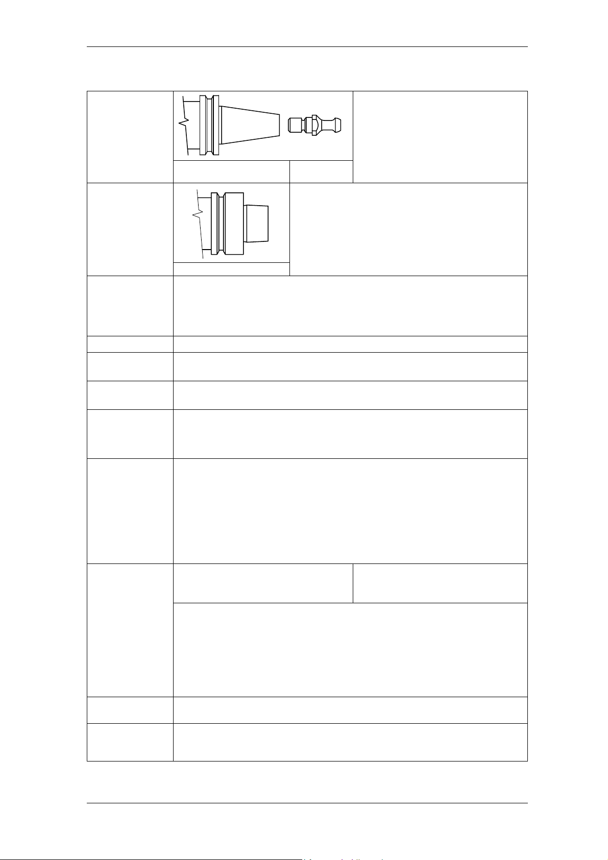
ISO 30
HSK
Value of the balancing of a rotating object in accordance with standard ISO 1940/1,
Level or class
of dynamic
balancing
Rated voltage
Rated
frequency
Nominal
characteristics
Service S1
Service S6
Torque and
Power
Coolant
Scheduled
maintenance
indicated by the letter G.
Low values for G indicate a higher degree of balancing; the maximum balancing
precision is G=0.4.
G takes on discrete values in relation to multiples of 2.5 (G=0.4 G=1 G=2.5 …).
Maximum supply voltage.
Minimum frequency corresponding to the maximum value for the supply voltage.
All the various rated values reached in relation to the rated frequency.
Operation under constant load, with a duration sufficient to allow the motor to attain a
thermal equilibrium.
The corresponding abbreviation is S1.
(Standard IEC EN 60034-1)
Sequence of identical operating cycles, each comprising a period of operation under
constant load and a period of operation without load while maintaining the rotational
speed; there is no rest period.
The corresponding abbreviation is S6, followed by the percentage ratio between the
period of operation under load and the length of the cycle.
Example: S6 40%
(40% period of operation with load, 60% period of operation in rotation but without
load)
(Standard IEC EN 60034-1)
Providing a precise physical definition of torque and power would be going beyond
the scope and possibility of this manual. Nevertheless the torque can be roughly
correlated to the force with which the tool contacts the piece being machined (and
with equal torque, the force increases as the diameter of the tool decreases). Power,
on the other hand, is proportional to the torque and the rotational speed and
determines the maximum machining speed (taking into consideration the
performance of the tool, the characteristics of the material being machined and the
type of machining).
Fluid, liquid or gas (including air) by means of which the heat is transferred from the
spindle to the atmosphere.
All the activities intended to maintain the operating and functioning conditions of the
product as provided for by HSD S.p.A. at the moment of its launch on the market; it is
carried out through scheduled operations to adjust, repair and replace parts.
CONE ISO30
DIN 69871
CONE HSK - DIN 69893
60 W×()
CNm()
-----------------------------
=
2 π× rpm×
Tool holder cone hooking system,
described by the standard DIN 69871.
The electrospindle has a plate similar to
that shown in the next image, indicating
TIE-ROD HSD
0804H0009
Tool holder cone hooking system, described by standard
DIN 69893.
The electrospindle has a plate similar to that shown in
the next image, indicating the type of mounting.
the type of mounting.
C = Torque
W = Power
rpm = revolutions per minute
015-it_Info-Pre2.fm
HSD S.p.A.
10
Page 11

HSD
1.7 Warranty
HSD S.p.A. guarantees that the product has been inspected at its plant with a positive result.
Works under warranty shall be performed free at the HSD S.p.A. facilities, transport at the
customer's expense; HSD S.p.A. shall not be liable for termination of production during the
warranty period.
The warranty does not cover faults due to normal wear of those parts which, by their nature, are
subject to rapid and continuous wear (e.g. gaskets, belts, bearings, etc.). In particular, HSD S.p.A.
gives no guarantee as to the service life of the bearings, as this depends on various factors
including: the degree of balancing of the tools, the types of machining operation, collisions and/or
mechanical stresses beyond the values indicated by the manufacturer.
HSD S.p.A. accepts no liability for faults in the conformity of the product caused by a failure to
observe the instructions contained in the instruction manual, or due to incorrect operation or
handling of the product. The buyer shall therefore have a right to replacement of parts found
to be defective only if the faults have not been caused by tampering with the product
namely by installing non-original HSD spare parts
not provided for and not authorised in the present manual, and in all cases without the prior
written approval of HSD S.p.A.
On no account shall HSD S.p.A. or its suppliers be responsible for damage (including but
not limited to damage to the physical integrity of the product or damages due to loss or
reduced earnings, stoppages in production, loss of information or other economic losses)
resulting from the use of HSD products, even in cases where HSD S.p.A. has been warned
of the possibility of such damage.
and/or by replacement of components
,
The buyer's warranty shall be voided if HSD S.p.A. is not notified in detail in writing of the nature of
any faults discovered in the product within 15 days of the fault being discovered. The buyer's
warranty shall also be voided in the event that he does not allow the seller to carry out any
requested inspections or if the seller requests the defective parts to be returned to the works and
the buyer fails to return them within two weeks of the request.
Measured drawings and photographs are provided purely as reference examples for a simpler
understanding of the text.
In line with its policy of continuous development and advancement of the product, the company
reserves the right to modify either its functional or aesthetic characteristics, to vary the design of
any functional element or accessory, or to suspend production and delivery; this without
undertaking to give notice to anyone and without incurring any other obligation. In addition, HSD
S.p.A. reserves the right to make any structural or functional modification, as well as modifications
to the supply of spare parts and accessories, without the obligation to communicate these changes
to anyone and for any reason.
015-it_Info-Pre2.fm
HSD S.p.A.
11
Page 12
HSD
2 Transport, packaging, unpacking,
2 Transport, packaging, unpacking, storage
2.1 Warnings
Lifting and handling the product may create hazardous situations for the persons involved; we
therefore recommend that the instructions given by HSD S.p.A. are observed and that only
suitable tools are used.
The installation and assembly operations must always be carried out by specialised
technicians only.
We recommend that all lifting and handling operations of the product or its parts be carried out
with great care, avoiding collisions that could compromise the proper functioning, or damage
coated parts.
The user is responsible for selecting the lifting equipment (ropes, straps or chains,
etc.) considered most suitable in terms of both functionality and lifting capacity, with
regard to the weight indicated on the packaging and on the product label.
2.2 Dimensions and weights
Product crate for shipment:
- the gross weight is specified on the packaging;
- the packaging linear dimensions are specified in the documents supplied with the product.
Unpacked product:
- the weight (according to the version) is indicated in chapter 3 “Technical specifications”;
- dimensional drawings are available upon request at the customer service.
2.3 Transport and Packaging Conditions
The product is shipped protected by a covering of VCI plastic and expanded foam, packed in a
wooden crate or case of special cardboard.
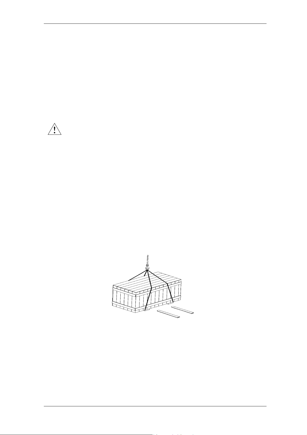
The figure below shows a few methods of lifting the packed product (using ropes and using a forklift truck; in the latter case, ensure that during lifting the centre of gravity of the crate is always
between the two forks).
The examples shown are only indications, as it is not possible to determine in advance all the
possible configurations for lifting a product manufactured by HSD S.p.A.
020-it_Trasp.fm
HSD S.p.A.
12
Page 13
HSD
2 Transport, packaging, unpacking,
2.4 Unpacking Procedure
Before opening the package, check that the seals on the package are not
broken
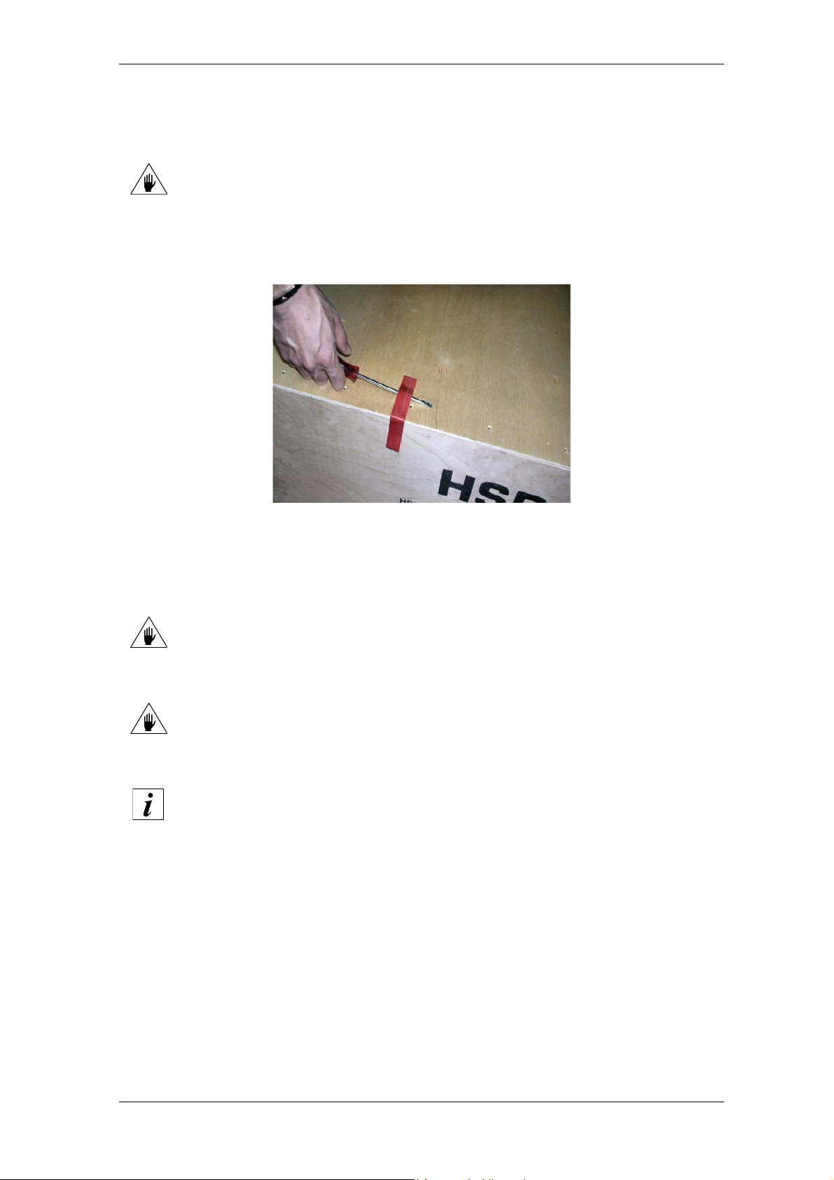
If the product is packed in a wooden crate, insert a screwdriver under the locking hook. Lever it
open, paying attention not to damage the packaging and its contents.
If the product is packed in a cardboard case, remove the strip of adhesive tape, paying attention
not to damage the package and its contents.
Do not lift the product by holding it from the electric fan section (if provided), in
order not to damage the guard.
Do not rest the product on the spindle shaft .
The expanded foam and plastic cover can be disposed of as plastic material.
2.5 Storage
If the product is to be stored, it must be protected against the weather, moisture, dust and
aggressive atmospheric and environmental agents.
It is therefore necessary:
to carry out periodic checks to ensure the good general condition of conservation;
to manually rotate the shaft (roughly once a month) to maintain optimum lubrication of the
bearings.
STORAGE TEMPERATURE: from -5°C (+23°F) to +55°C (+131°F)
RELATIVE HUMIDITY (NON-CONDENSING): from 5% to 55%
020-it_Trasp.fm
HSD S.p.A.
13
Page 14
HSD
3 Technical specifications
3 Technical specifications
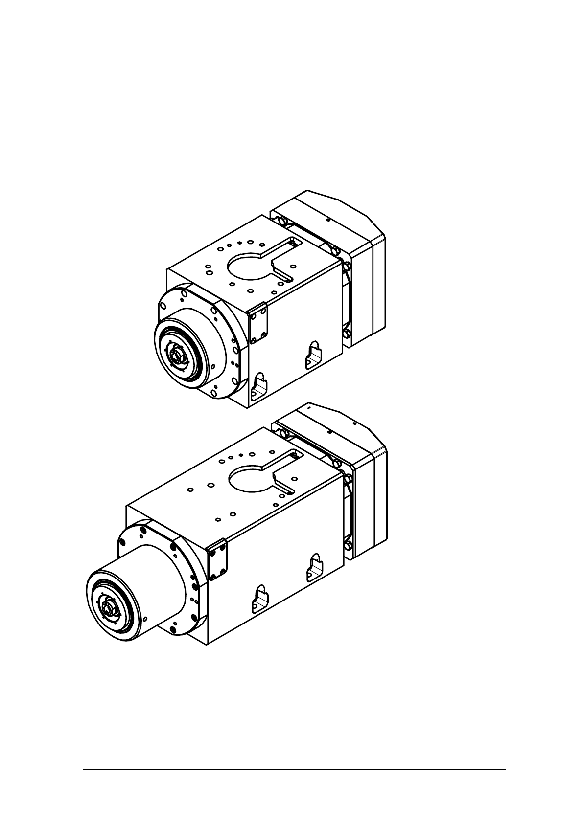
ES779
ES789
031-it_Parti.fm
HSD S.p.A.
14
Page 15
HSD
3.1 Main parts
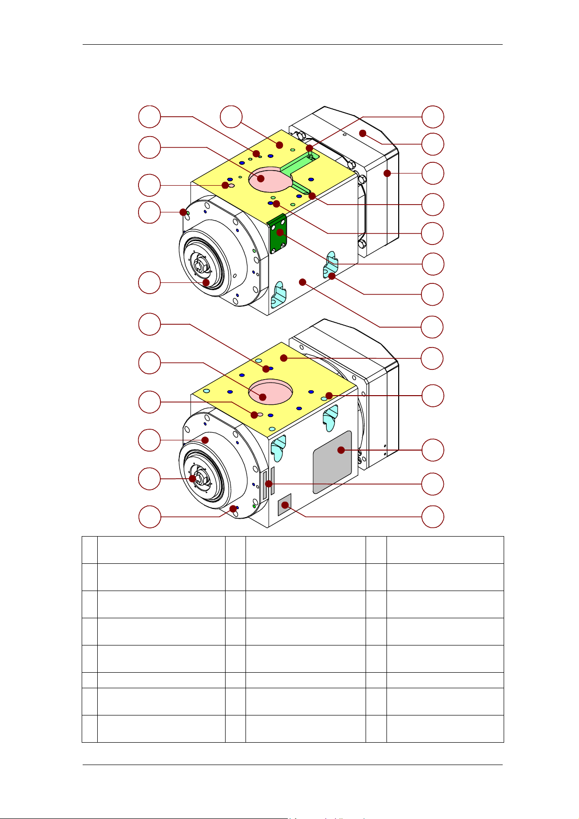
3.1.1 ES779 non connectorised, with fixing bores
3 Technical specifications
2
3
4
5
6
7
8
9
1
13
14
15
16
17
18
19
20
21
19
10
22
11
12
1 Resting surface 9
6 bores for compressed air
2
and fluid inlet / outlet
H8 bore Ø60, depth 6
3
for positioning
H7 bore Ø8, depth 10
4
for positioning
2 M6 bores for tool
5
lubricant-coolant outlet
6 Shaft 14 Sensor area 22 EC marking plate
6 M8 bores, thread depth
7
12 for fastening
H8 bore Ø60, depth 6
8
for positioning
H7 bore Ø8, depth 10 for
positioning
10 Nose 18 Encoder compartment
11 HSK collet 19
6 M5 bores
12
for accessories
13 Engine cable passage 21 Resting surface
15 Cylinder 23 Serial number
16 Sensor cable passage 24 Description of tool holder
6 M8 bores, thread depth
17
12 for fastening
4 through bores Ø8.5
for fastening
20 Framework
23
24
031-it_Parti.fm
HSD S.p.A.
15
Page 16
HSD
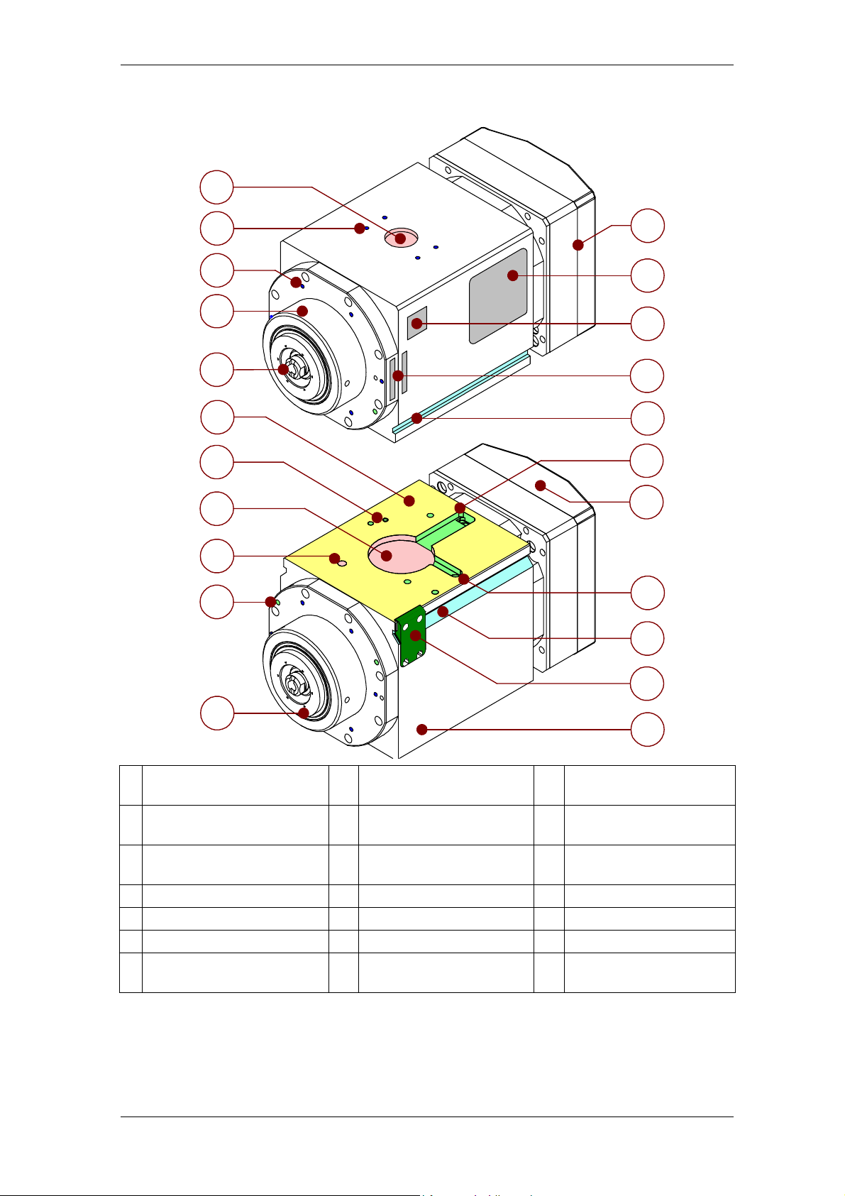
3.1.2 ES779 non connectorised, with fixing grooves
1
3 Technical specifications
2
3
4
5
6
7
8
9
10
12
13
14
15
16
17
18
19
16
20
11
21
1 H8 bore Ø30, depth 4 8
4 M5 bores, thread depth 6
2
for accessories
3 6 M5 bores for accessories 10
4 Nose 11 Shaft 18 Sensor area
5 HSK collet 12 Cylinder 19 Sensor cable passage
6 Resting surface 13 EC marking plate 20 Encoder compartment
6 bores for compressed air
7
and fluid inlet / outlet
H8 bore Ø60, depth 6
for positioning
H7 bore Ø8, depth 10 for
9
positioning
2 M6 bores for tool
lubricant-coolant outlet
14 Description of tool holder 21 Framework
15 Serial number
16 Fixing groove
17 Engine cable passage
031-it_Parti.fm
HSD S.p.A.
16
Page 17
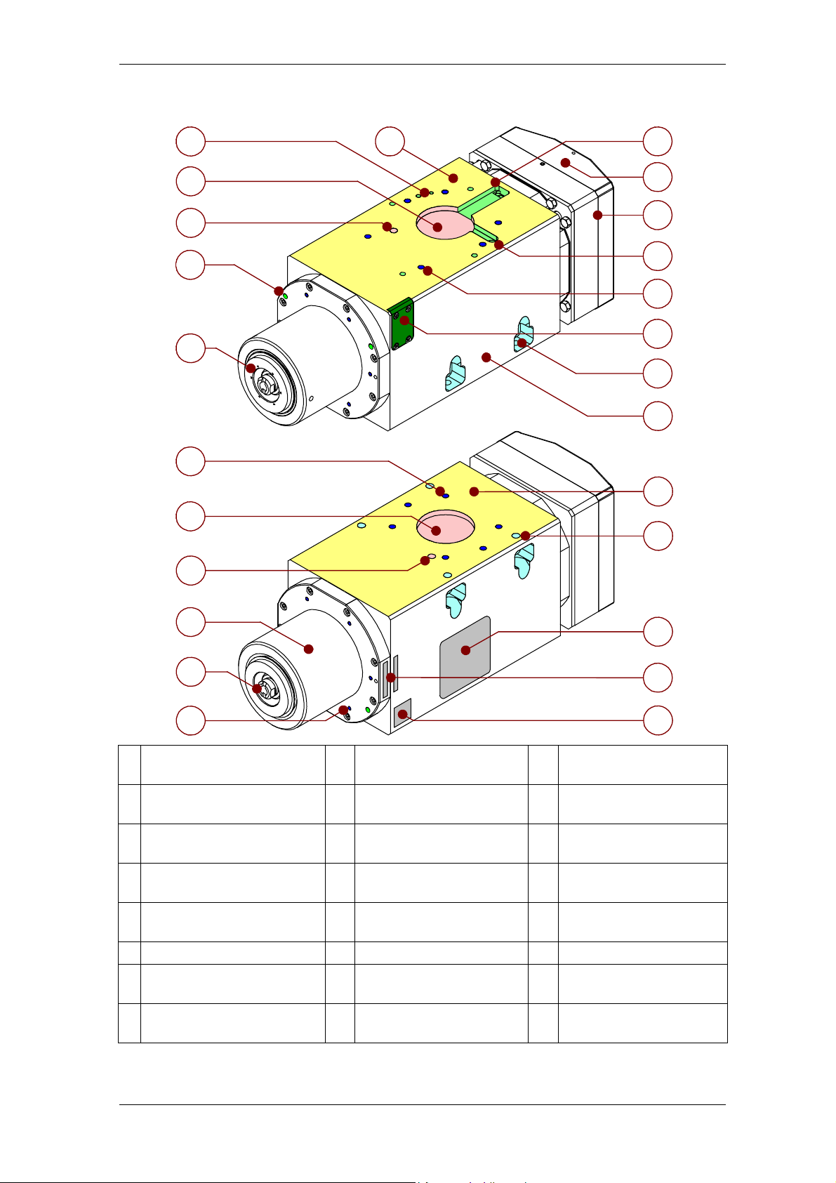
HSD
3.1.3 ES789 non connectorised, with fixing bores
3 Technical specifications
2 1
3
4
5
6
7
8
13
14
15
16
17
18
19
20
21
19
9
10
11
12
1 Resting surface 9
6 bores for compressed air
2
and fluid inlet / outlet
H8 bore Ø60, depth 6
3
for positioning
H7 bore Ø8, depth 10
4
for positioning
2 M6 bores for tool
5
lubricant-coolant outlet
6 Shaft 14 Sensor area 22 EC marking plate
6 M8 bores, thread depth
7
12 for fastening
H8 bore Ø60, depth 6
8
for positioning
H7 bore Ø8, depth 10 for
positioning
10 Nose 18 Encoder compartment
11 HSK collet 19
6 M5 bores
12
for accessories
13 Engine cable passage 21 Resting surface
15 Cylinder 23 Serial Number
16 Sensor cable passage 24 Description of tool holder
6 M8 bores, thread depth
17
12 for fastening
4 through bores Ø8.5
for fastening
20 Framework
22
23
24
031-it_Parti.fm
HSD S.p.A.
17
Page 18
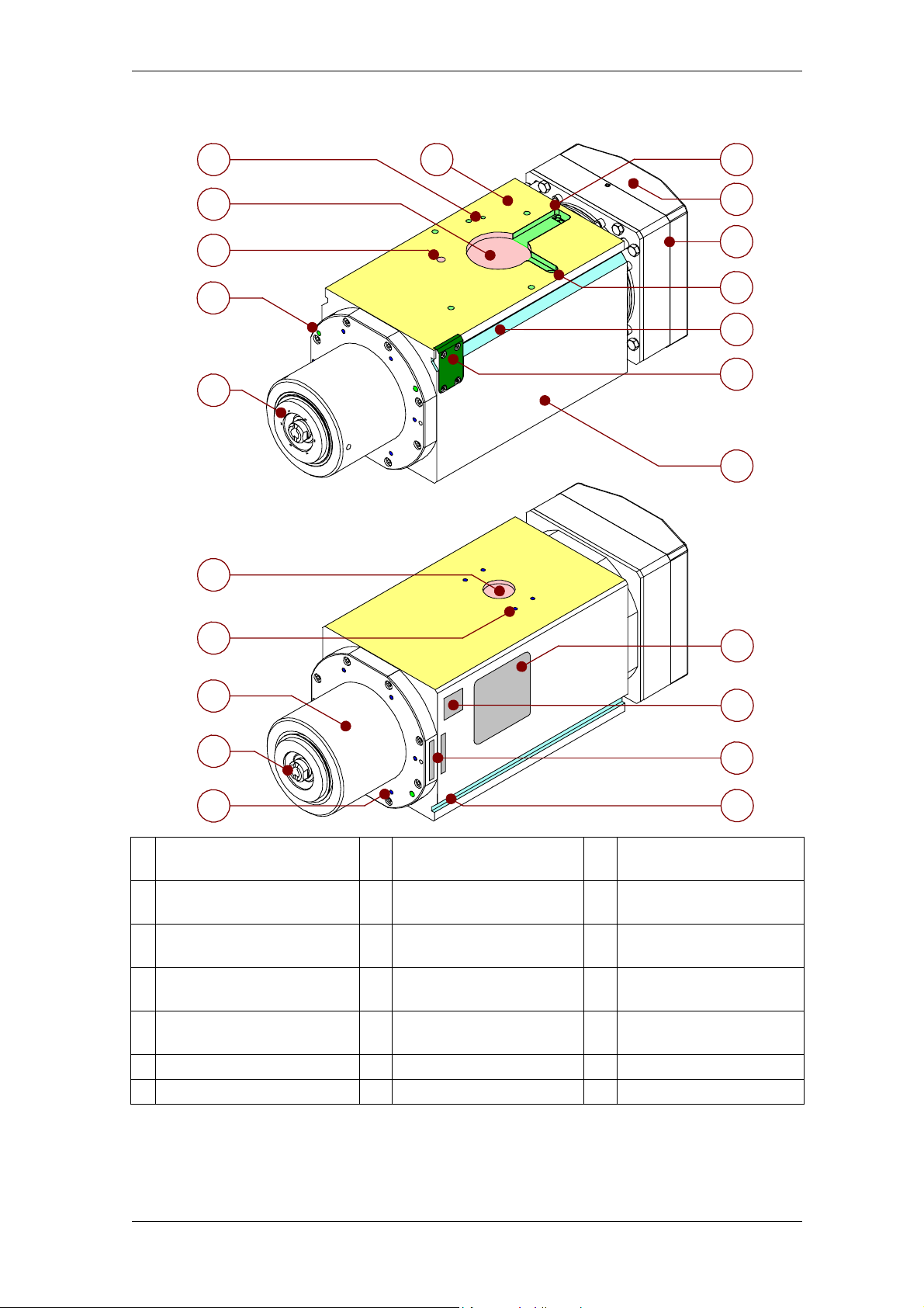
HSD
3.1.4 ES789 non connectorised, with fixing grooves
3 Technical specifications
2
3
4
5
6
7
1 12
13
14
15
16
17
18
8
9
10
11
1 Resting surface 8
6 bores for compressed air
2
and fluid inlet / outlet
H8 bore Ø60, depth 6
3
for positioning
H7 bore Ø8, depth 10
4
for positioning
2 M6 bores for tool
5
lubricant-coolant outlet
6 Shaft 13 Sensor area 20 Description of tool holder
7 H8 bore Ø30, depth 4 14 Cylinder 21 Serial number
4 M5 bores, thread depth
6 for accessories
9 Nose 16 Fixing groove
10 HSK collet 17 Encoder compartment
6 M5 bores
11
for accessories
12 Engine cable passage 19 EC marking plate
15 Sensor cable passage
18 Framework
19
20
21
16
031-it_Parti.fm
HSD S.p.A.
18
Page 19
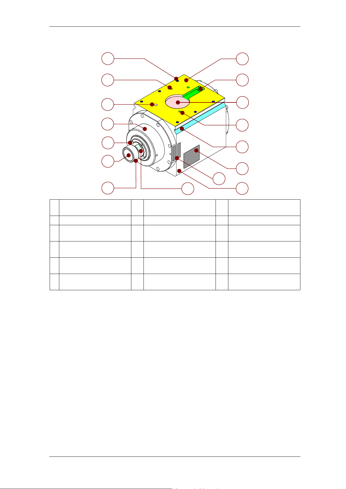
HSD
3.1.5 ES779 Collet, non connectorised
3 Technical specifications
1
2
3
4
5
8
9
10
11
12
6
13
14
7
6 M8 bores, thread depth
1
16 for fastening
2 Pressurisation air inlet 8 Resting surface 14 Serial number
H7 bore Ø8, depth 10
3
for positioning
4 Nose 10
5 Shaft 11
6 ER32 collet seat 12
M40 thread, 1.5 step
7
for ring nut
9 Engine cable passage 15 Slot for CH34 wrench
H8 bore Ø60, depth 6
for positioning
2 bores for coolant inlet /
outlet
Fixing groove
(one per side)
15
13 EC marking plate
16 Framework
16
031-it_Parti.fm
HSD S.p.A.
19
Page 20
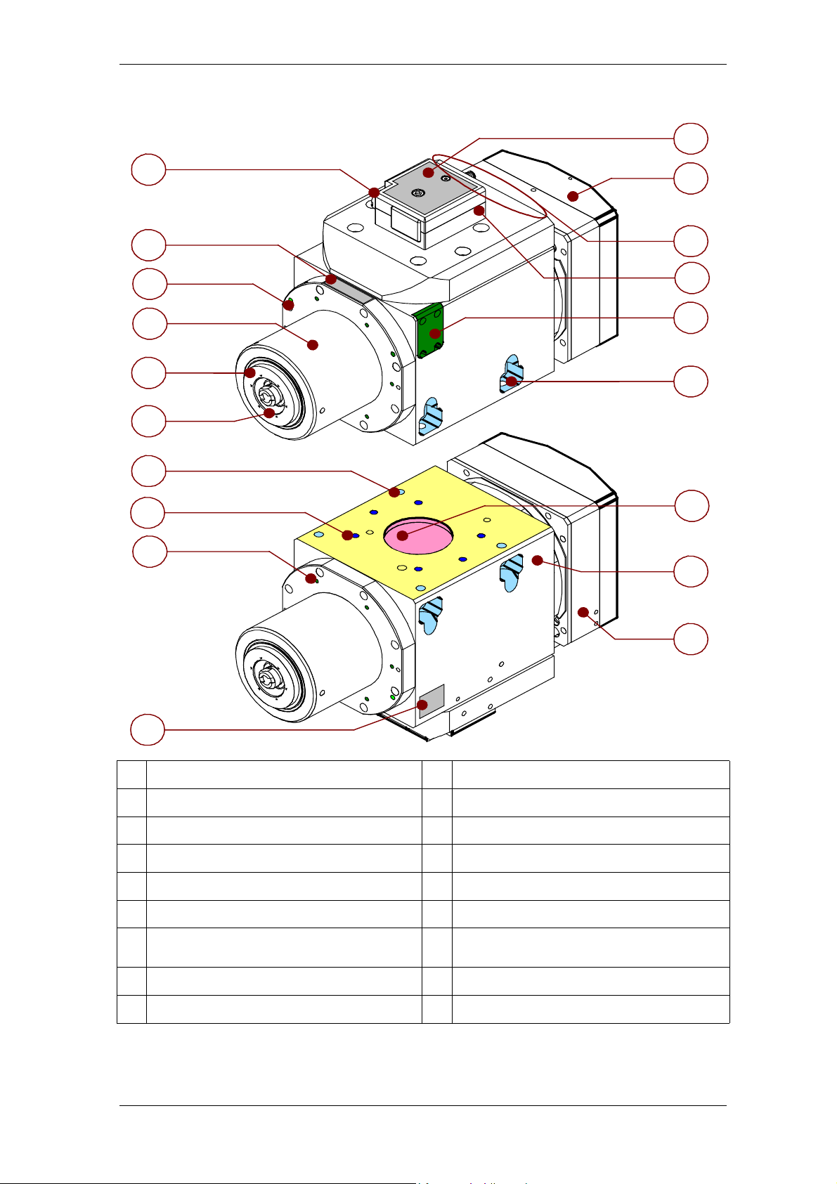
HSD
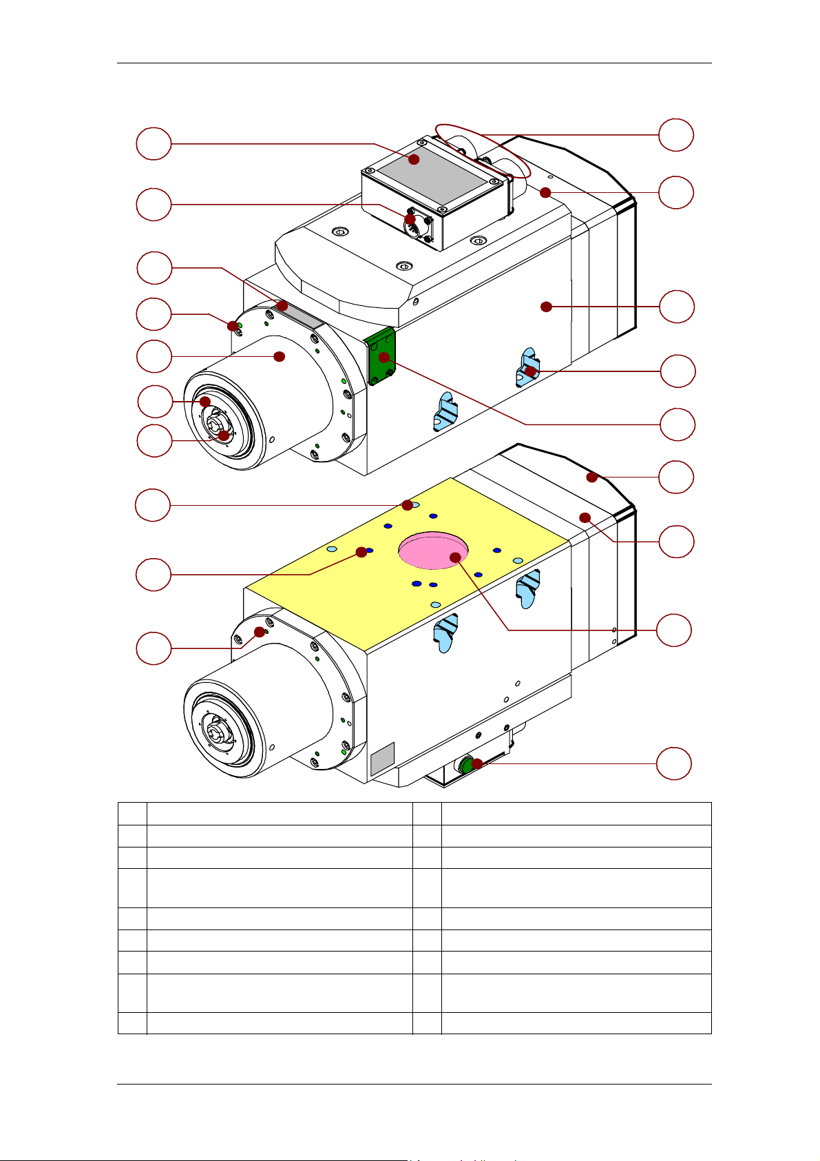
3.1.6 Variations for versions with electrical connectors of HSD type
3 Technical specifications
11
1
2
5
6
7
8
3
4
9
12
13
14
15
7
16
17
10
1 Button for manual tool unlocking 10 Description of tool holder
2 Serial number 11 EC marking plate
3 2 M6 bores for tool lubricant-coolant outlet 12 Sensor area
4 Nose 13 Hydraulic/pneumatic connectors
5 Shaft 14 HSD electrical connector
6 HSK collet 15 Encoder compartment
4 through bores Ø8.5
7
for fastening
8 6 M8 bores, thread depth 12 for fastening 17 Framework
9 6 M5 bores for accessories 18 Cylinder
H8 bore Ø60, depth 6
16
for positioning
18
031-it_Parti.fm
HSD S.p.A.
20
Page 21
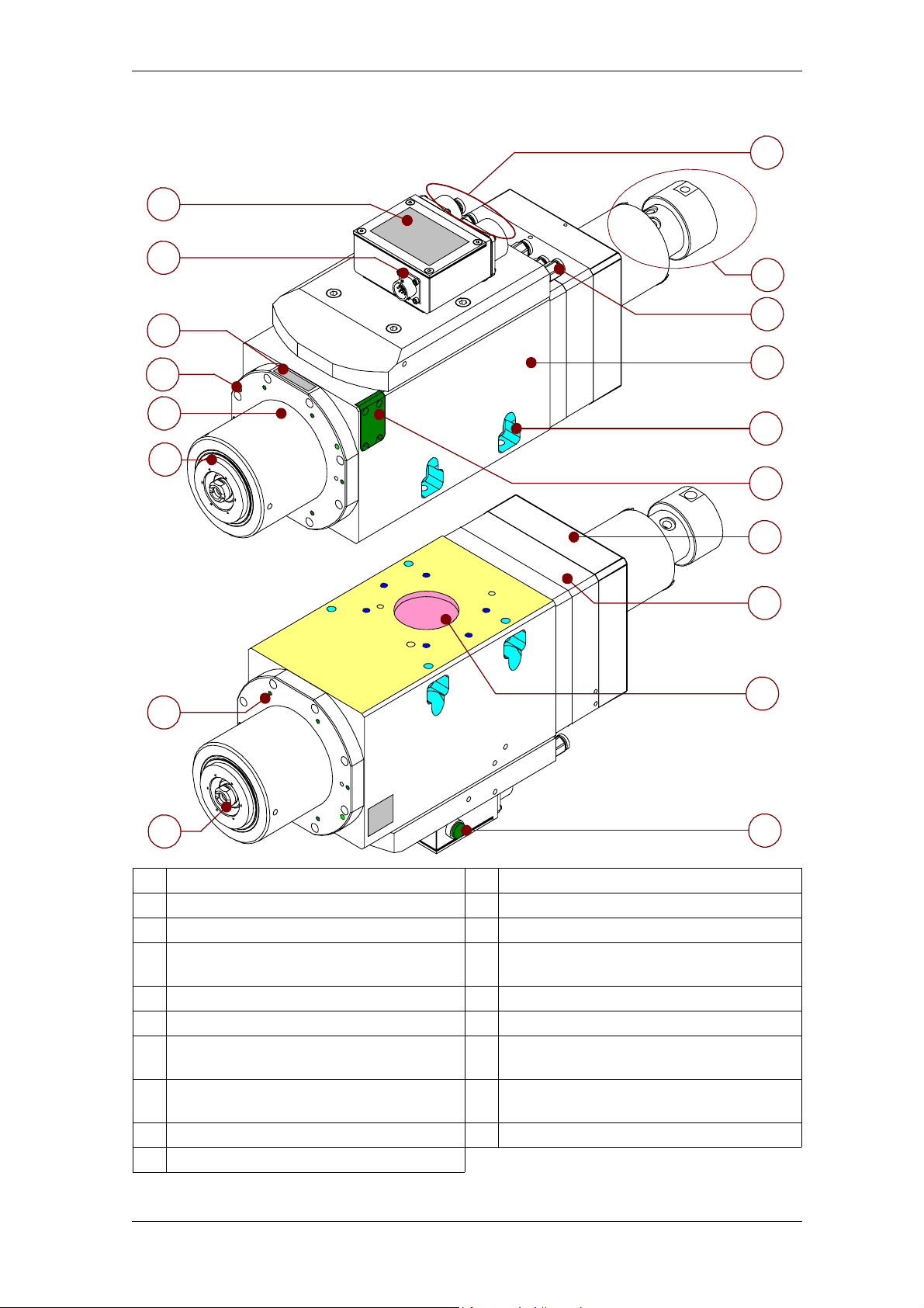
HSD
3.1.7 Variations for versions with MIL standard electrical connectors
3 Technical specifications
1
2
3
4
5
7
8
11
12
13
8
6
14
15
9
17
10
18
1 EC marking plate 10 6 M5 bores for accessories
2 Electrical connector (encoder) 11 Electrical connectors (standard MIL)
3 Serial number 12 Hydraulic/pneumatic connector zone
2 M6 bores for tool lubricant-coolant
4
outlet
5 Nose 14 Encoder compartment
6 Shaft 15 Sensor area
7 HSK collet 16 Cylinder
4 through bores Ø8.5
8
for fastening
9 6 M8 bores, thread depth 12 for fastening 18 Button for manual tool unlocking
13 Framework
H8 bore Ø60, depth 6
17
for positioning
16
031-it_Parti.fm
HSD S.p.A.
21
Page 22
HSD
3.1.8 ES789 variations with distributor
1
2
3
3 Technical specifications
11
12
13
4
14
5
8
6
15
16
17
18
9
10
1 EC marking plate 11 Electrical connectors (standard MIL)
2 Electrical connector (encoder) 12 Fluids distributor
3 Serial number 13 Hydraulic/pneumatic connector zone
2 M6 bores for tool lubricant-coolant
4
outlet
5 Nose 15 Encoder compartment
6 Shaft 16 Sensor area
4 through bores Ø8.5
7
for fastening
8 6 M8 bores, thread depth 12 for fastening 18
9 6 M5 bores for accessories 19 Button for manual tool unlocking
10 HSK collet
031-it_Parti.fm
14 Framework
17 Cylinder
H8 bore Ø60, depth 6
for positioning
HSD S.p.A.
19
22
Page 23

HSD
3.1.9 Variations with floating piston or fixed piston
21
1 Floating piston 2 Fixed piston
3 Technical specifications
031-it_Parti.fm
HSD S.p.A.
23
Page 24
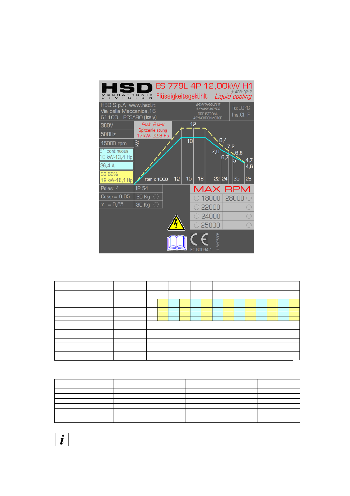
HSD
H1423H0212 Rev.03 (SP.120.80.44)
Tensione nominale (*)
Nennspannung (*) Rated voltage (*)
V
310 380 380 380 380 380 380
Frequenza nominale Nennfrequenz
Rated frequency
Hz
400 500 600 733 800 833 933
Velocità nominale
Nominale
Geschwin digkeit
Rated speed
rpm
12000 15000 18000 22000 24000 25000 28000
Tipo di se rvizio
Betriebsart
Duty type
S1
cont
S6
60%
S1
cont
S6
60%
S1
cont
S6
60%
S1
cont
S6
60%
S1
cont
S6
60%
S1
cont
S6
60%
S1
cont
S6
60%
Potenza nominale
Nennleistung Rated power
kW
10
12
10
12
10
12
7
8,4
6,7
7,2
5
6,6
4,6
4,7
Coppia nominale
Nenndrehmoment Rated torque
Nm
8
9,6
6,4
7,6
5,3
6,4
3
3,7
2,7
2,9
1,8
2,5
1,6
1,6
Corrente nominale
Nennstrom Rated current
A
31
37,5
26,4
31,5
26
31
20
24
18,6
20
13,7
18
12
12,5
Rendimento nominale
η
Nennwirkungsgrad η Rated efficiency
η
0,85
Fattore di potenza cos
ϕ
Leistungsfaktor cos ϕ Power factor cos
ϕ
0,85
Numero di poli
Polzahl Number of poles
4
Classe di isolamento
Isolierklasse Insulation class
F
Tipo di raffreddamento
Kühlungstyp Type of cooling
Raffreddamento a liquido / Flüssigkeit / Liquid cooling
Peso versione
NASO CORTO
Gewicht Version
KURZE NASE
Weight of SHORT
NOSE variant
kg
26
Peso versione
NASO LUNGO
Gewicht Version
LANG NASE
Weight of LONG
NOSE variant
kg
30
[(*) fornita da inverter ]
[(*) von Inverter
geliefert]
[(*) from inver ter]
Versioni disponibili - Verfügbare Versionen - Available models
ATTACCO PORTAUTENSILE CUSCINETTI ANTERIORI CUSCINETTI POSTERIORI VELOCITÀ MASSIMA
WERKZEUGHALTER VORDERE LAGER HINTERE LAGER MAX. DREHZAHL
TOOL HOLDER FRONT BEARINGS REAR BEARINGS MAX SPEED
HSK A63
CERAMICI / KERAMIK / CERAMIC CERAMICI / KERAMIK / CERAMIC 18000rpm
HSK E63
CERAMICI / KERAMIK / CERAMIC CERAMICI / KERAMIK / CERAMIC 18000rpm
HSK F63
CERAMICI / KERAMIK / CERAMIC ACCIAIO / STAHL / STEEL
22000rpm
HSK E40 - F50
CERAMICI / KERAMIK / CERAMIC ACCIAIO / STAHL / STEEL
24000rpm
HSK F63
CERAMICI / KERAMIK / CERAMIC CERAMICI / KERAMIK / CERAMIC
25000rpm
HSK E40 - F50
CERAMICI / KERAMIK / CERAMIC CERAMICI / KERAMIK / CERAMIC
28000rpm
3.2 Characteristics and performance
3.2.1 ES779 12kW with 500Hz (15,000 rpm) rated frequency
The maximum value of rated current “S1/cont” is used to set the parameter of
the “maximum direct current” of the inverter
032-it_Sp-Elet.f.fm
HSD S.p.A.
24
Page 25

HSD
Equivalent electrical network SP.120.80.44
Rated power (S1/Cont) kW 10
Rated current (S1/Cont) A26.4
Rated voltage V380
Rated speed rpm 11,810
Rated frequency Hz 400
No-load line voltage V300
No-load current A7.5
Stator resistance (20°C) Ohm 0.11
Rotor resistance (20°C) Ohm 0.16
Stator leakage reactance Ohm 0.9
Rotor leakage reactance Ohm 1.9
Main field reactance Ohm 23
Field weakening initial speed rpm 15,000
Motor maximum speed rpm 28,000
Power factor 0.85
Rotor moment of inertia kg 1.5E-03
Connection Y/D Y
032-it_Sp-Elet.f.fm
HSD S.p.A.
25
Page 26
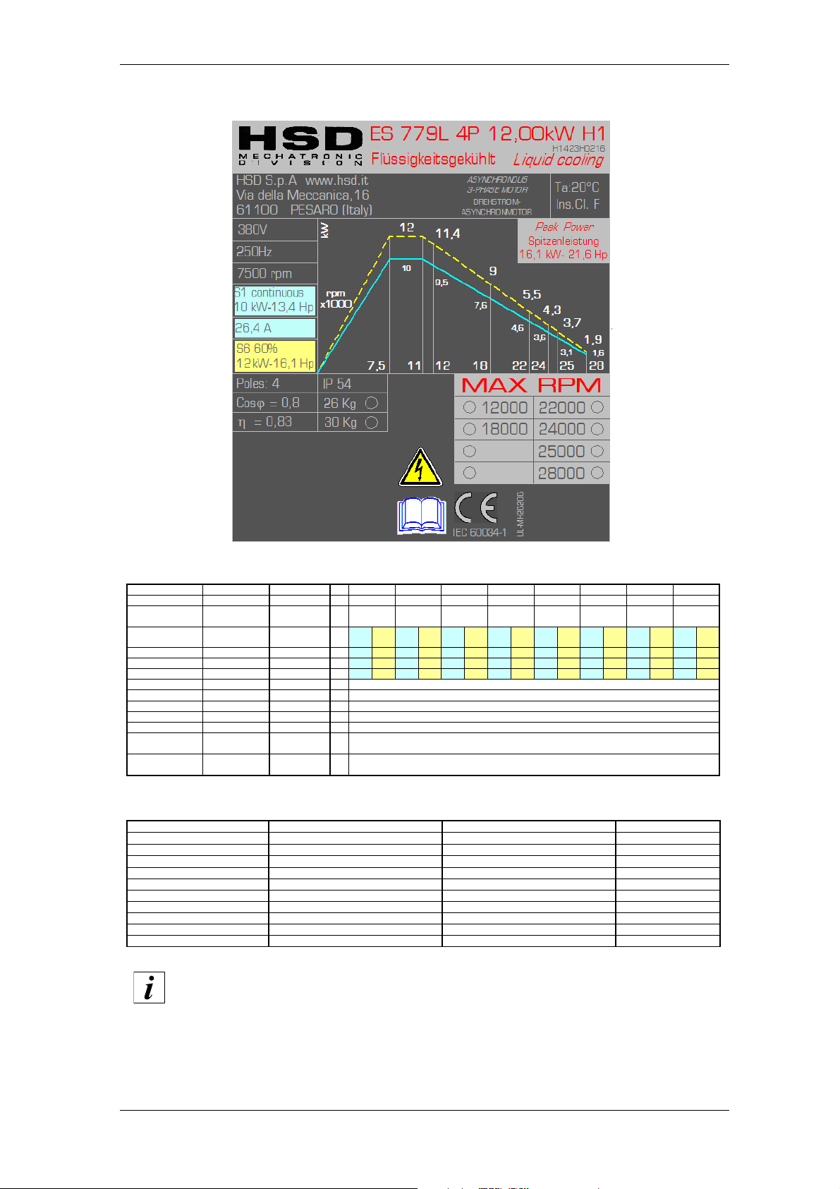
HSD
H1423H0216 Rev.05 (SP.120.080.45)
Tensione nominale (*)
Nennspannung (*) Rated voltage (*)
V
380 380 380 380 380 380 380 380
Frequenza nominale Nennfrequenz
Rated frequency
Hz
250 367 400 600 733 800 833 933
Velocità nominale
Nominale
Geschwin digkeit
Rated speed
rpm
7500 11000 12000 18000 22000 24000 25000 28000
Tipo di se rvizio
Betriebsart
Duty type
S1
cont
S6
60%
S1
cont
S6
60%
S1
cont
S6
60%
S1
cont
S6
60%
S1
cont
S6
60%
S1
cont
S6
60%
S1
cont
S6
60%
S1
cont
S6
60%
Potenza nominale
Nennleistung Rated power
kW
10
12
10
12
9,5
11,4
7,9
9
4,6
5,5
3,6
4,3
3,1
3,7
1,6
1,9
Coppia nominale
Nenndrehmoment Rated torque
Nm
12,7
15,3
8,7
10,4
7,6
9,1
4,2
4,8
2
2,4
1,4
1,7
1,2
1,4
0,55
0,65
Corrente nominale
Nennstrom Rated current
A
24
29
22,6
27,1
21,5
25,8
17,8
20,4
13,6
16,3
10
12
8,5
10,2
5,2
6,2
Rendimento nominale
η
Nennwirkungsgrad η Rated efficiency
η
0,83
Fattore di potenza cos
ϕ
Leistungsfaktor cos ϕ Power factor cos
ϕ
0,8
Numero di poli
Polzahl Number of poles
4
Classe di isolamento
Isolierklasse Insulation class
F
Tipo di raffreddamento
Kühlungstyp Type of cooling
Raffreddamento a liquido / Flüssigkeit / Liquid cooling
Peso versione
NASO CORTO
Gewicht Version
KURZE NASE
Weight of SHORT
NOSE variant
kg
26
Peso versione
NASO LUNGO
Gewicht Version
LANG NASE
Weight of LONG
NOSE variant
kg
30
[(*) fornita da inverter ]
[(*) von Inverter
geliefert]
[(*) from inver ter]
Versioni disponibili - Verfügbare Versionen - Available models
ATTACCO PORTAUTENSILE CUSCINETTI ANTERIORI CUSCINETTI POSTERIORI VELOCITÀ MASSIMA
WERKZEUGHALTER VORDERE LAGER HINTERE LAGER MAX. DREHZAHL
TOOL HOLDER FRONT BEARINGS REAR BEARINGS MAX SPEED
HSK A63
CERAMICI / KERAMIK / CERAMIC CERAMICI / KERAMIK / CERAMIC
18000rpm
HSK E63
CERAMICI / KERAMIK / CERAMIC CERAMICI / KERAMIK / CERAMIC
18000rpm
HSK F63
CERAMICI / KERAMIK / CERAMIC ACCIAIO / STAHL / STEEL
22000rpm
HSK F63
CERAMICI / KERAMIK / CERAMIC CERAMICI / KERAMIK / CERAMIC
25000rpm
HSK E40 - F50
ACCIAIO / STAHL / STEEL ACCIAIO / STAHL / STEEL
12000rpm
HSK E40 - F50
CERAMICI / KERAMIK / CERAMIC ACCIAIO / STAHL / STEEL
24000rpm
HSK E40 - F50
CERAMICI / KERAMIK / CERAMIC CERAMICI / KERAMIK / CERAMIC
28000rpm
HSK E40 - F50
CERAMICI / KERAMIK / CERAMIC CERAMICI / KERAMIK / CERAMIC
28000rpm
3.2.2 ES779 12kW DP with 250Hz (7,500 rpm) rated frequency
The maximum value of rated current “S1/cont” is used to set the parameter of
the “maximum direct current” of the inverter
032-it_Sp-Elet.f.fm
HSD S.p.A.
26
Page 27

HSD
Equivalent electrical network SP 120.80.45
Rated power (S1/Cont) kW 10
Rated current (S1/Cont) A24
Rated voltage V380
Rated speed rpm 7,250
Rated frequency Hz 250
No-load line voltage V354
No-load current A11
Stator resistance (20°C) Ohm 0.26
Rotor resistance (20°C) Ohm 0.24
Stator leakage reactance Ohm 1.1
Rotor leakage reactance Ohm 1.78
Main field reactance Ohm 17
Field weakening initial speed rpm 7,500
Motor maximum speed rpm
Power factor 0.8
Rotor moment of inertia kg 1.1E-03
Connection Y/D Y
032-it_Sp-Elet.f.fm
HSD S.p.A.
27
Page 28
HSD
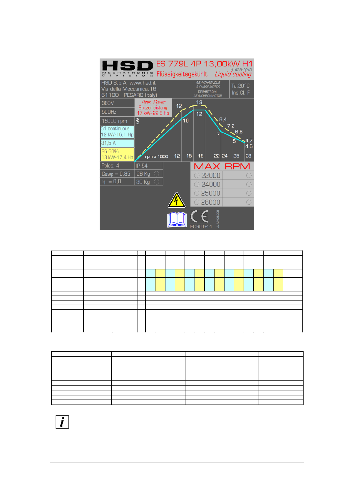
3.2.3 ES779 13kW with 500Hz (15,000 rpm) rated frequency
H1423H0240 Rev.01 (SP.120.80.44.Par)
Tensione nominale (*)
Frequenza nominale Nennf requenz
Velocità nominale
Tipo di servizio
Potenza nominale
Coppia nominale
Corrente nominale
Rendimento nominale η
Fattore di potenza c os ϕ
Numero d i poli
Classe di isolamento
Tipo di raffreddamento
Peso versione
NASO CORTO
Peso versione
NASO LUNG O
[(*) fornita da inverter]
Nennspannung (*) Rated voltage (*)
Geschwindigkeit
Nennleistung Rated power
Nenndrehmoment Rated t orque
Nennwirkungsgrad η Rated efficiency
Leistungsfaktor cos ϕ Power factor cos
Isolierklasse Insulation cl ass
Kühlungstyp Type of cooling
Gewicht Version
KURZE NASE
Gewicht Version
LANG NASE
[(*) von Inverter
geliefert]
Rated frequency
Nominale
Betriebsart Duty type
Nennstrom Rated current
Polzahl Number of poles
Rated speed
Weight of SHORT
NOSE variant
Weight of LONG
NOSE variant
[(*) from inverter]
V 310 380 380 380 380 380 380
Hz
400 500 600 733 800 833 933
rpm 12000 15000 18000 22000 24000 25000 28000
S1
S6
S1
S6
S1
S6
S1
S6
S1
S6
S1
S6
S1
cont
60%
cont
60%
cont
60%
cont
60%
cont
60%
cont
kW
10 12 12 13 12 13 7 8,4 6,7 7,2 5 6,6 4,6 4,7
Nm 8 9,6 7,6 8,2 6,4 6,9 3 3,7 2,7 2,9 1,8 2,5 1,6 1,6
A 31 37,5 31,5 34,1 31 33,6 20 24 18,6 20 13,7 18 12 12,5
η
ϕ
Raffreddamento a liquido / Flüssigkeit / Liquid cooling
kg 26
kg
0,8
0,85
4
F
30
60%
cont
S6
60%
Versioni disponibili - Verfügbare Versionen - Available models
ATTACCO PORTAUTENSILE CUSCINETTI ANTERIORI CUSCINETTI POSTERIORI VELOCITÀ MASSIMA
WERKZEUGHALTER VORDERE LAGER HINTERE LAGER MAX. DREHZAHL
TOOL HOLDER FRONT BEARINGS REAR BEARINGS MAX SPEED
HSK F63 CERAMICI / KERAMIK / CERAMIC ACCIAIO / STAHL / STEEL 22000rpm
HSK F63 CERAMICI / KERAMIK / CERAMIC CERAMICI / KERAMIK / CERAMIC 25000rpm
HSK E40 - F50 CERAMICI / KERAMIK / CERAMIC ACCIAIO / STAHL / STEEL 24000rpm
HSK E40 - F50 CERAMICI / KERAMIK / CERAMIC CERAMICI / KERAMIK / CERAMIC 28000rpm
032-it_Sp-Elet.f.fm
The maximum value of rated current “S1/cont” is used to set the parameter of
the “maximum direct current” of the inverter
HSD S.p.A.
28
Page 29

HSD
Equivalent electrical network SP 120.80.44 par
Rated power (S1/Cont) kW 12
Rated current (S1/Cont) A31.5
Rated voltage V380
Rated speed rpm 11,810
Rated frequency Hz 400
No-load line voltage V300
No-load current A7.5
Stator resistance (20°C) Ohm 0.11
Rotor resistance (20°C) Ohm 0.16
Stator leakage reactance Ohm 0.9
Rotor leakage reactance Ohm 1.9
Main field reactance Ohm 23
Field weakening initial speed rpm 15,000
Motor maximum speed rpm 28,000
Power factor 0.85
Rotor moment of inertia kg 1.5E-03
Connection Y/D Y
032-it_Sp-Elet.f.fm
HSD S.p.A.
29
Page 30

HSD
3.2.4 ES779 13.5kW with 400Hz (12,000 rpm) rated frequency
H1423H0378 Rev.00 (SP. 120.080.4S)
Tensione nominale (*)
Frequenza nominale Nennfrequenz
Velocità nominale
Tipo di servizio
Potenza nominale
Coppia nominale
Corrente nominale
Rendimento nominale η
Fattore di potenza cos ϕ
Numero di poli
Classe di isolamento
Tipo di raffreddamento
Peso versione
NASO CORTO
Peso versione
NASO LUNGO
[(*) fornita da inverter]
Versioni disponibili - Verfügbare Versionen - Available models
ATTACCO PORTAUTENSILE CUSCI NETTI ANTERIORI CUSCINETTI POSTERIORI VELOCITÀ MASSIMA
WERKZEUGHALTER VORDERE LAGER HINTERE LAGER MAX. DREHZAHL
TOOL HOLDER FRONT BEARINGS REAR BEARINGS MAX SPEED
HSK A63
Nennspannung (*) Rated voltage (*)
Nominale
Geschwindigkeit
Betriebsart Duty type
Nennleistung Rated power
Nenndrehmoment Rated torque
Nennstrom Rated current
Nennwirkungsgrad η Rated efficiency
Leistungsfaktor cos ϕ Power factor cos
Polzahl Number of poles
Isolierklasse Insulation class
Kühlungstyp Type of cooling
Gewicht Version
KURZE NASE
Gewicht Version
LANG NASE
[(*) von Inverter
geliefert]
CERAMICI / KERAMIK / CERAMIC ACCIAIO / STAHL / STEEL
Rated frequency
Rated speed
η
ϕ
Weight of SHORT
NOSE variant
Weight of LONG
NOSE variant
[(*) from inverter]
380 380 380 380
V
400 600 667 800
Hz
12000 18000 20000 24000
rpm
S1
S6
S1
S6
S1
cont
60%
cont
13,5 16,2 13,5 16,2 11,5 13,8 7,5 9
kW
10,7 12,9 7,2 8,6 5,5 6,6 3,0 3,6
Nm
29,0 35,0 29,0 35,0 25,0 30,0 16,5 19,8
A
60%
0,85
0,82
Raffreddamento a liquido / Flüssigkeit / Liquid cooling
kg
kg
26
30
S6
cont
60%
4
F
18000rpm
S1
cont
S6
60%
The maximum value of rated current “S1/cont” is used to set the parameter of
the “maximum direct current” of the inverter
032-it_Sp-Elet.f.fm
HSD S.p.A.
30
Page 31

HSD
Equivalent electrical network SP 120.80.4S
Rated power (S1/Cont) kW 13.5
Rated current (S1/Cont) A29
Rated voltage V380
Rated speed rpm 11,830
Rated frequency Hz 400
No-load line voltage V 369.56
No-load current A5.6
Stator resistance (20°C) Ohm 0.18
Rotor resistance (20°C) Ohm 0.13
Stator leakage reactance Ohm 2.1
Rotor leakage reactance Ohm 1.3
Main field reactance Ohm 37.6
Field weakening initial speed rpm 12,000
Motor maximum speed rpm 24,000
Power factor 0.82
Rotor moment of inertia kg
Connection Y/D
032-it_Sp-Elet.f.fm
HSD S.p.A.
31
Page 32
HSD
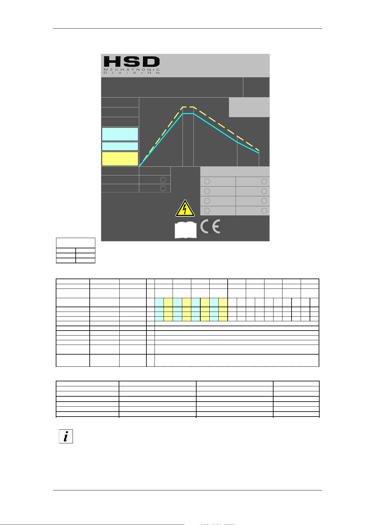
3.2.5 ES789 18kW with 267Hz (8,000 rpm) rated frequency
HSD S.p.A www.hsd.it
Via della Meccanica,16
61100 PESARO (Italy)
380V
W
W
W
W
k
k
k
k
267Hz
8000 rpm
S1
continuous
ES 789L 4P 18,00kW H1
..
Liquid cooling
18
18
1818
16
16
1616
Flussigkeitsgekuhlt
ASYNCHRONOUS
3-PHASE MOTOR
DREHSTROM-
ASYNCHRONMOTOR
H1423H0211
..
Ta:20°C
Ins.Cl. F
Peak Power
Spitzenleistung
19 kW - 25,5 Hp
10
10
1010
16 kW-21,5 Hp
8888
18181822
22000
UL-MH26206
22
2222
5,
5,2222
5,5,
4,
4,3333
4,4,
PEAK CURRENT
120 A 500 ms
145 A 15 ms
170 A 5 ms
34,5 A
S6 60%
18 kW-24,1 Hp
Poles: 4
ϕ
= 0,7
Cos
η
= 0,8
IP 54
36 Kg
42 Kg
rp
rpm
m x 1
rprp
m m
x 1000000000000
x 1x 1
10
10 18
8888
1010
MMMMAAAAXXXX RRRRPPPPMMMM
18000
IEC 60034-1
H1423H0211 Rev.02 (2120H0120)
Tensione nominale (*)
Frequenza nominale Nennfrequenz
Velocità nominale
Tipo di servizio
Potenza nominale
Coppia nominale
Corrente no minale
Rendimento nominale η
Fattore di potenza cos ϕ
Numero di p oli
Classe di isolamento
Tipo di raffreddamento
Peso versione
NASO LUNGO
Peso versione con
DISTRIBUT ORE
[(*) fornita da inverter]
ATTACCO PORTAUTENSILE CUSCINETTI ANTERIORI CUSCINETTI POSTERIORI VELOCITÀ MASSIMA
WERKZEUGHALTER VORDERE LAGER HINTERE LAGER MAX. DREHZAHL
TOOL HOLDER FRONT BEARINGS REAR BEARINGS MAX SPEED
Nennspan nung (*) Rated voltage (*)
Geschwindigkeit
Betriebsa rt Duty type
Nennleistung Rat ed power
Nenndrehmoment Rated torque
Nennstrom Rated current
Nennwirkungsgrad η Rated efficiency
Leistungsfaktor cos ϕ Power factor cos
Isolierklasse Insulation class
Kühlungstyp Type of cooling
Gewicht V ersion
LANGE NASE
Gewicht V ersion
DISTRIBUTOR
[(*) von Inverter
geliefert]
HSK F63 CERAMICI / KERAMIK / CERAMIC ACCIAIO / STAHL / STEEL 18000rpm
HSK F63 CRONIDUR / CHROMEX CERAMICI / KERAMIK / CERAMIC 22000rpm
Rated frequency
Nominale
Polzahl Number of poles
Rated speed
Weight of LONG
NOSE variant
DISTRIBUTOR
[(*) from inverter]
V 380 380 380 380
Hz 267 333 600 733
rpm 8000 10000 18000 22000
S1
S6
S1
S6
S1
S6
S1
cont
60%
cont
60%
cont
kW 16 18 16 18 8 10 4,3 5,2
Nm 19 21,5 15,3 17,2 4.2 5,3 1,9 2, 3
A 34,5 45 34,5 45 18 26 8 11
0,8
η
0,7
ϕ
4
F
Raffreddamento a liquido / Flüssigkeit / Liquid cooling
kg 36
Weight of
42
variant
60%
cont
S6
60%
032-it_Sp-Elet.f.fm
The maximum value of rated current “S1/cont” is used to set the parameter of
the “maximum direct current” of the inverter
HSD S.p.A.
32
Page 33

HSD
Equivalent electrical network SP 120.150.4A
Rated power (S1/Cont) kW 16
Rated current (S1/Cont) A34.5
Rated voltage V380
Rated speed rpm 7,810
Rated frequency Hz 267
No-load line voltage V266
No-load current A11
Stator resistance (20°C) Ohm 0.12
Rotor resistance (20°C) Ohm 0.2
Stator leakage reactance Ohm 1
Rotor leakage reactance Ohm 1.7
Main field reactance Ohm 19
Field weakening initial speed rpm 8,000
Motor maximum speed rpm 18,000
Power factor 0.8
Rotor moment of inertia kg 0.0025
Connection Y/D Y
032-it_Sp-Elet.f.fm
HSD S.p.A.
33
Page 34
HSD
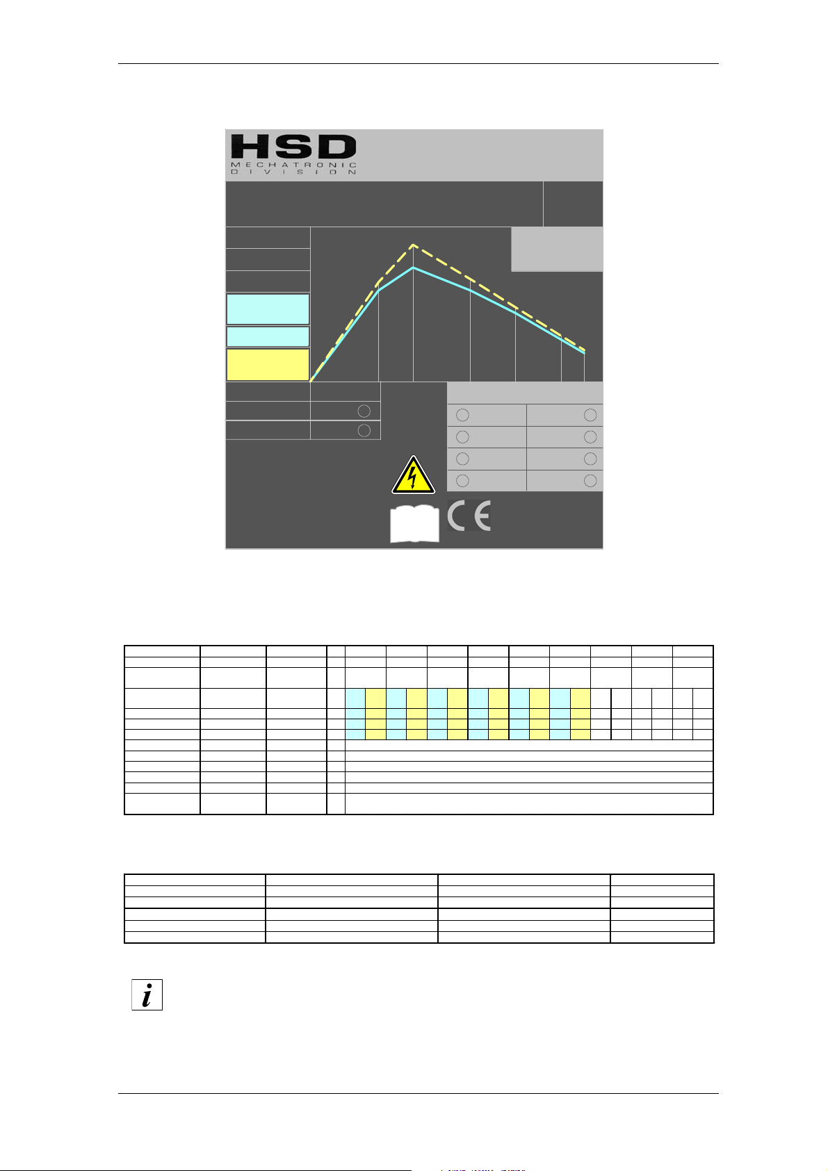
3.2.6 ES789 18kW DP with 300Hz (9,000 rpm) rated frequency
HSD S.p.A www.hsd.it
Via della Meccanica,16
61100 PESARO (Italy)
380V
rpm x 1 000
300Hz
9000 rpm
S1
continuous
15 kW-20,1 Hp
31,6 A
kW
S6 60%
18 kW-24,1 Hp
Poles: 4
M = 0,8
Cos
K
= 0,8
IP 54
Kg
36 Kg
ES 789L 4P
..
Flussigkeitsgekuhlt
18
13,1
15
12
9
6
IEC 60034-1
18,00
..
ASYNCHRONOUS
3-PHASE MOTOR
DREHSTROM-
ASYNCHRONMOTOR
kW H1
H1423H0228
Liquid cooling
Ta:20°C
Ins.Cl. F
Peak Power
Spitzenleistung
13,5
12
14 18
21,8 kW-29,2 Hp
9,8
9
5,5
22
6
3,8
MAX RPM
18000
22000
24000
UL-MH26206
4,1
24
H1423H0228 Rev.02 (SP.120.150.4E)
Tensione nominale (*)
Frequenza nominale Nennfrequenz
Velocità nominale
Tipo di servizio
Potenza nominale
Coppia nominale
Corrente nominale
Rendimento nominale
Fattore di potenza cos
Numero di poli
Classe di isolamento
Tipo di raffreddamento
Peso versione
NASO LUNGO
[(*) fornita da inverter]
Nennspannung (*) Rated voltage (*)
Geschwindigkeit
Nennleistung Rated power
Nenndrehmoment
K
Nennwirkungsgrad K Rated efficiency
M
Leistungsfaktor cos M Power factor cos
Isolierklasse Insulation class
Kühlungstyp T ype of cooling
Gewicht Version
LANGE NASE
[(*) von Inverter
geliefert]
Rated frequency
Nominale
Betriebsart Duty type
Nennstrom Rated current
Polzahl Number of poles
Rated speed
Rated torque
Weight of LONG
NOSE variant
[(*) from inverter]
V 255 380 380 380 380 380
Hz 200 300 467 600 733 800
rpm 6000 9000 14000 18000 22000 24000
S1
contS660% S1contS660% S1cont
kW 12 13,1 15 18 12 13,5 9 9,8 5,5 6 3,8 4,1
Nm 19,1 20,9 15,9 19,1 8,2 9,2 4,8 5,2 2,4 2,6 1,5 1,6
A 36,8 41,3 31,6 38,7 29,1 32,8 24,3 26,4 16,2 17,6 11,1 12,2
0,8
K
0,8
M
4
F
kg 36
S6
60% S1contS660% S1contS660%
Raffreddamento a liquido / Flüssigkeit / Liquid cooling
S1
cont S660%
Versioni disponibili - Verfügbare Versionen - Available models
ATTACCO PORTAUTENSILE CUSCINETTI ANTERIORI CUSCINETTI POSTERIORI VELOCITÀ MASSIMA
WERKZEUGHALTER VORDERE LAGER HINTERE LAGER MAX. DREHZAHL
TOOL HOLDER FRONT BEARINGS REAR BEARINGS MAX SPEED
HSK F63 CERAMICI / KERAMIK / CERAMIC ACCIAIO / STAHL / STEEL 18000rpm
HSK F63 CERAMICI / KERAMIK / CERAMIC CERAMICI / KERAMIK / CERAMIC 22000rpm
HSK F63 CERAMICI / KERAMIK / CERAMIC CERAMICI / KERAMIK / CERAMIC 24000rpm
The maximum value of rated current “S1/cont” is used to set the parameter of
the “maximum direct current” of the inverter
032-it_Sp-Elet.f.fm
HSD S.p.A.
34
Page 35

HSD
Equivalent electrical network SP 120.150.4E
Rated power (S1/Cont) kW 15
Rated current (S1/Cont) A33
Rated voltage V380
Rated speed rpm 8,880
Rated frequency Hz 300
No-load line voltage V373
No-load current A6.4
Stator resistance (20°C) Ohm 0.13
Rotor resistance (20°C) Ohm 0.14
Stator leakage reactance Ohm 1.7
Rotor leakage reactance Ohm 1.26
Main field reactance Ohm 34
Field weakening initial speed rpm 9,000
Motor maximum speed rpm 24,000
Power factor 0.8
Rotor moment of inertia kg 3.8E-03
Connection Y/D Y
032-it_Sp-Elet.f.fm
HSD S.p.A.
35
Page 36
HSD
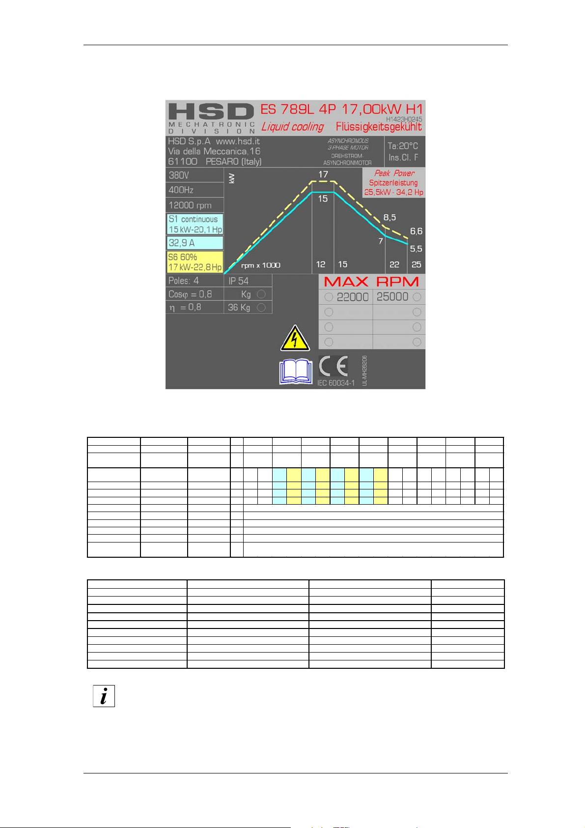
3.2.7 ES789 17kW with 400Hz (12,000 rpm) rated frequency
H1423H0245 Rev.01 (SP.120.150.45)
Tensione nominale (*)
Frequenza nominale Nennfrequenz
Velocità nominale
Tipo di servizio
Potenza nominale
Coppia nominale
Corrente nominale
Rendimento nominale η
Fattore di potenza cos ϕ
Numero d i poli
Classe di isolamento
Tipo di raffreddamento
Peso versione
NASO LUNG O
[(*) fornita da inverter]
Nennspannung (*) Rate d voltage (*)
Geschwindigkeit
Nennleistung Rated power
Nenndrehmoment Rated torqu e
Nennwirkungsgrad η Rat ed efficiency
Leistungsfaktor cos ϕ Power factor cos
Isolierklasse Insulation class
Kühlungstyp Ty pe of cooling
Gewicht Version
LANGE NASE
[(*) von Inverter
geliefert]
Rated frequency
Nominale
Betriebsart Duty type
Nennstrom Rated current
Polzahl Number of poles
Rated speed
Weight of LONG
NOSE variant
[(*) from inverter]
V 380 380 380 380
Hz 400 500 733 833
rpm 12000 15000 22000 25000
S1
S6
S1
S6
S1
S6
S1
S6
kW 15 17 15 17 7 8,5 5,5 6, 6
Nm 12 13,5 9,6 10,8 3 3,6 2,1 2,5
A 34 38 34 38 16,5 20 15,9 18,8
0,8
η
0,8
ϕ
4
F
Ra ffreddamento a liquido / F lüssigk eit / Liquid cooling
kg 36
cont
60%
cont
60%
cont
60%
cont
60%
ATTACCO PORTAUTENSILE CUSCINETTI ANTERIORI CUSCINETTI POSTERIORI VELOCITÀ MASSIMA
WERKZEUGHALTER VORDERE LAGER HINTERE LAGER MAX. DREHZAHL
TOOL HOLDER FRONT BEARINGS REAR BEARINGS MAX SPEED
HSK F63 CERAMICI / KERAMIK / CERAMIC ACCIAIO / STAHL / STEEL 22000rpm
HSK F63 CRONIDUR / CHROMEX CERAMICI / KERAMIK / CERAMIC 25000rpm
The maximum value of rated current “S1/cont” is used to set the parameter of
the “maximum direct current” of the inverter
032-it_Sp-Elet.f.fm
HSD S.p.A.
36
Page 37

HSD
Equivalent electrical network SP 120.150.45
Rated power (S1/Cont) kW 15
Rated current (S1/Cont) A34
Rated voltage V380
Rated speed rpm 11748
Rated frequency Hz 400
No-load line voltage V364
No-load current A9.5
Stator resistance (20°C) Ohm 0.09
Rotor resistance (20°C) Ohm 0.13
Stator leakage reactance Ohm 0.61
Rotor leakage reactance Ohm 1.8
Main field reactance Ohm 27.9
Field weakening initial speed rpm 12000
Motor maximum speed rpm
Power factor 0.8
Rotor moment of inertia kg 2.5E-03
Connection Y/D Y
032-it_Sp-Elet.f.fm
HSD S.p.A.
37
Page 38
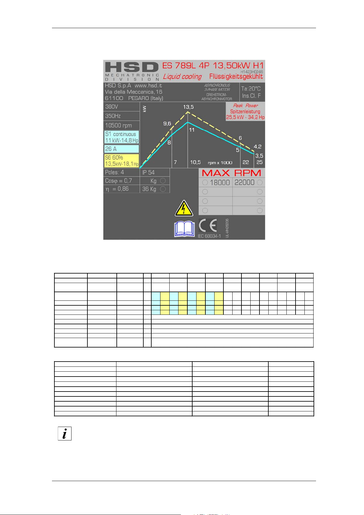
HSD
3.2.8 ES789 13.5kW with 350Hz (10,500 rpm) rated frequency
H1423H0246 Rev.01 (SP.120.150.49)
Tensione nominale (*)
Frequenza nominale Nennfrequenz
Velocità nominale
Tipo di servizio
Potenza nominale
Coppia nominale
Corrente nominale
Rendimento nominale η
Fattore di potenza cos ϕ
Numero d i poli
Classe di isolamento
Tipo di raffreddamento
Peso versione
NASO LUNG O
[(*) fornita da inverter]
ATTACCO PORTAUTENSILE CUSCINETTI ANTERIORI CUSCINETTI POSTERIORI VELOCITÀ MASSIMA
WERKZEUGHALTER VORDERE LAGER HINTERE LAGER MAX. DREHZAHL
Nennspannung (*) Rate d voltage (*)
Geschwindigkeit
Betriebsart Duty type
Nennleistung Rated power
Nenndrehmoment Rated torque
Nennstrom Rated current
Nennwirkungsgrad η Rat ed efficiency
Leistungsfaktor cos ϕ Power factor cos
Isolierklasse Insulation class
Kühlungstyp Ty pe of cooling
Gewicht Version
LANGE NASE
[(*) von Inverter
geliefert]
Rated frequency
Nominale
Polzahl Number of poles
Rated speed
Weight of LONG
NOSE variant
[(*) fro m inverter]
V 380 380 380 380
Hz 233 350 733 833
rpm 7000 10500 22000 25000
S1
S6
S1
S6
S1
S6
S1
S6
cont
60%
cont
60%
cont
60%
kW 8 9,6 11 13,5 5 6 3,5 4,2
Nm 10,9 13,1 10 12,3 2,2 2,6 1,3 1,6
A 27,5 33 26 32,5 13,3 16 9, 5 11
0,86
η
0,7
ϕ
4
F
Raffreddament o a liquido / Flüssigkeit / Liquid cooling
kg 36
cont
60%
TOOL HOLDER FRONT BEARINGS REAR BEARING S MAX SPEED
HSK F63 CERAMICI / KERAMIK / CERAMIC ACCIAIO / STAHL / STEEL 22000rpm
HSK F63 CRONIDUR / CHROMEX CERAMICI / KERAMIK / CERAMIC 25000rpm
The maximum value of rated current “S1/cont” is used to set the parameter of
the “maximum direct current” of the inverter
032-it_Sp-Elet.f.fm
HSD S.p.A.
38
Page 39

HSD
Equivalent electrical network SP 120.150.49
Rated power (S1/Cont) kW 11
Rated current (S1/Cont) A27.5
Rated voltage V380
Rated speed rpm 10,350
Rated frequency Hz 350
No-load line voltage V380
No-load current A6.0
Stator resistance (20°C) Ohm 0.14
Rotor resistance (20°C) Ohm 0.22
Stator leakage reactance Ohm 1.1
Rotor leakage reactance Ohm 1.8
Main field reactance Ohm 38
Field weakening initial speed rpm 10,500
Motor maximum speed rpm 20,000
Power factor 0.8
Rotor moment of inertia kg 25E-03
Connection Y/D Y
032-it_Sp-Elet.f.fm
HSD S.p.A.
39
Page 40

HSD
4 Installation and commissioning
4 Installation and commissioning
4.1 Dimensional drawings
Dimensional drawings are available upon request at HSD customer service.
4.2 Preliminary checks before installation
Before carrying out any operation, CHECK:
that no part of the product has suffered knocks or damage during the transport and/or
handling;
that connectors are not damaged.
4.3 Preparation of the auxiliary systems of the plant
It is the responsibility of the customer to have the auxiliary systems of the plant ready (e.g.
electrical system, air, etc.).
The electric power line must have the necessary transmission power. Connection to the electric
mains network may only be carried out by qualified persons.
The Customer is responsible for the whole electric power supply to the product
up to the connectors.
The user must ensure all the safety conditions necessary for the earthing of the
product.
The earthing system must conform to the standards in force in the country of
installation and must be inspected at regular intervals by qualified personnel.
050-it_Pre-Install.fm
HSD S.p.A.
40
Page 41
HSD
4.4 Mechanical connections
The supporting structure to which the product will be secured must be sufficiently stable for the
weight of the product and for the type of machining operation to be carried out.
4.4.1 Resting surface
The surface on which the electrospindle is to be fitted must
have a flatness less than 0.02 mm.
4.4.2 Tool change system
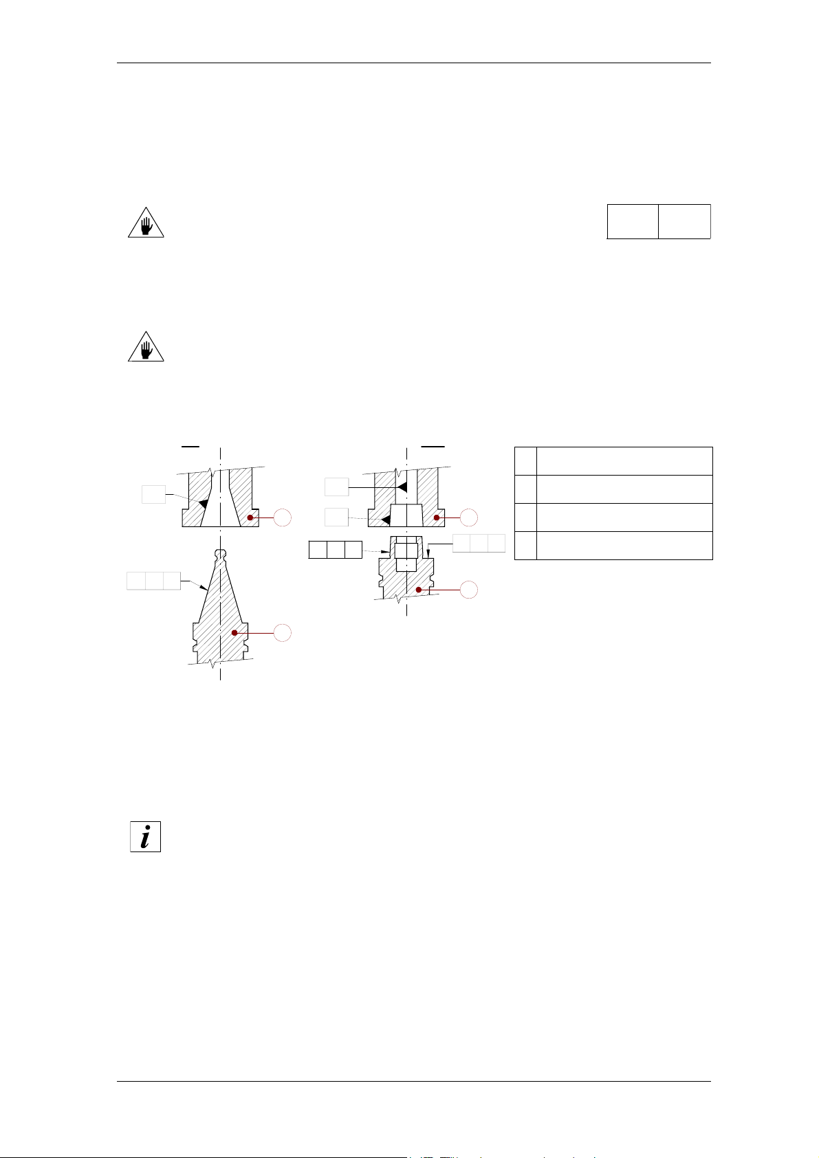
The tool holder magazine must position cones with the following precision:
ISO: spindle shaft/tool holder cone concentricity: 0.2 mm;
HSK: spindle shaft/tool holder cone concentricity: 0.7 mm
spindle shaft/tool holder stop surface perpendicularity: 0.1 mm.
ISO HSK
1 Spindle shaft ISO
r 0,02
-A-
a A0,2
-B-
1 3
2
-C-
a C0,7
n B0,1
4
2 Tool holder cone ISO
3 Spindle shaft HSK
4 Tool holder cone HSK
4.4.3 Fastening of models with “fixing bores”
To fit the machine electrospindle, choose any of the resting surfaces shown in figures of section 3
“Technical specifications”, with the corresponding fixing and positioning bores.
In particular, if the surface chosen has fixing bores either of the through or the threaded type,
simply use all the fixing bores of one type only.
In connectorised models, there is only one resting surface.
4.4.4 Fastening of models with “fixing grooves”
To fit the machine electrospindle, use 2 side grooves and positioning bores in the resting surface
(see figures in section 3 “Technical specifications”).
060-it_Mecca.fm
HSD S.p.A.
41
Page 42

HSD
4.4.5 “Collet” model fastening
To fasten the machine electrospindle, alternatively use 2 side grooves or threaded bores in the
resting surface; for the correct positioning, use 2 bores with specific tolerance on the resting
surface (see the figure in section 3.1).
4.4.6 Threaded service bores
There are six M5 threaded bores on the electrospindle nose to mount some accessories.
In models with “fixing grooves”, moreover, there are 4 M5 threaded bores on the surface opposite
to the resting surface.
(See figures in section 3 “Technical specifications”).
In “Collet” models, there are no service threaded bores.
4.5 Fluids distributor
Only for non connectorised versions: the interface surface that creates the
connection between the compressed air circuits/cooling liquids circuits and the
electrospindle must be made so as to prevent leaks and contamination between
the various ducts.
060-it_Mecca.fm
HSD S.p.A.
42
Page 43
HSD
4.6 Pneumatic connections
4.6.1 Specifications for compressed air to be supplied to HSD products
Inject compressed air with a purity rating complying with ISO 8573-1, types 2, 4, 3,
i.e:
• Type 2 for solid particles: size of solid particles < 1 µm.
• Type 4 for humidity: dew point < 3°C (37.4°F).
• Type 3 for total oil: oil concentration < 1 mg/m
Failure to comply with these specifications may result in electrospindle
malfunction.
The warranty is not valid if pollutants are found during repair operations.
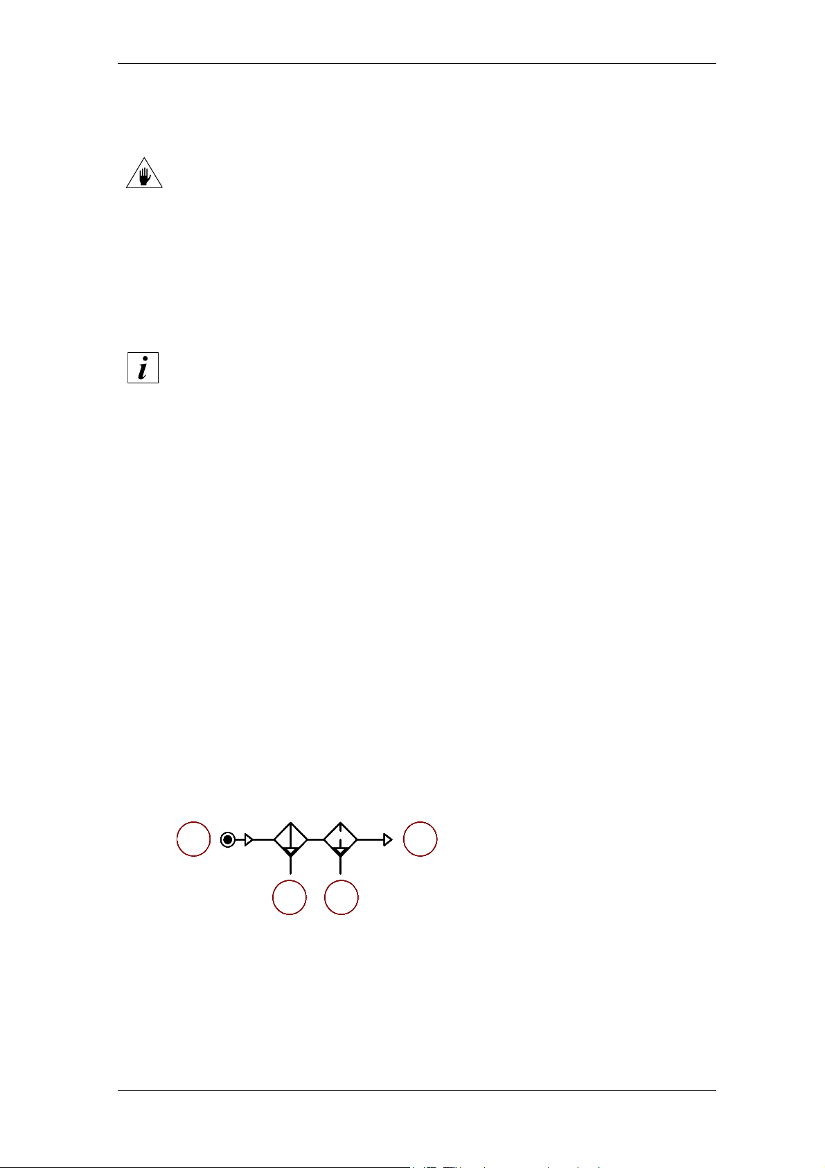
As an example, the above mentioned specifications can be implemented by
following the indications below:
If a lubricated air circuit is present in the machine, it should be isolated from the dry
air circuit (to be used by the electrospindle) by means of non-return valves.
The filters indicated in the diagrams of the following figures should be installed as
near the electrospindle as possible.
3
.
taking into account the fact that the efficiency of the filters is <100%, it is essential
that the machine be fed with properly treated air;
As a general guide, and for the circuits illustrated below, inject compressed air with a
purity rating complying with ISO 8573-1, types 7, 6, 4, i.e.:
• Type 7 for solid particles:
solid particle size < 40 µm;
solid particle concentration < 10mg/m3;
• Type 6 for humidity:
dew point < 10°C;
• Type 4 for total oil:
oil concentration < 5 mg/m3.
At the end of the working day, empty the pneumatic system to enable the automatic
purging of filters.
Carry out regular maintenance operations of the filters according to the
manufacturer's indications, and replace them when they are saturated and lose
effectiveness (approximately every 6/12 months).
1. Mains power supply.
1 4
1 4
1 4
1 4
1 4
1 4
1 4
1 4
1 4
1 4
1 4
1 4
32
32
32
32
32
32
32
32
32
32
32
32
2. Pre-filter 5 µm.
3. De-oiling filter 0.1 µm.
4. To the HSD product.
070-it_Cir-Pn.fm
HSD S.p.A.
43
Page 44
HSD
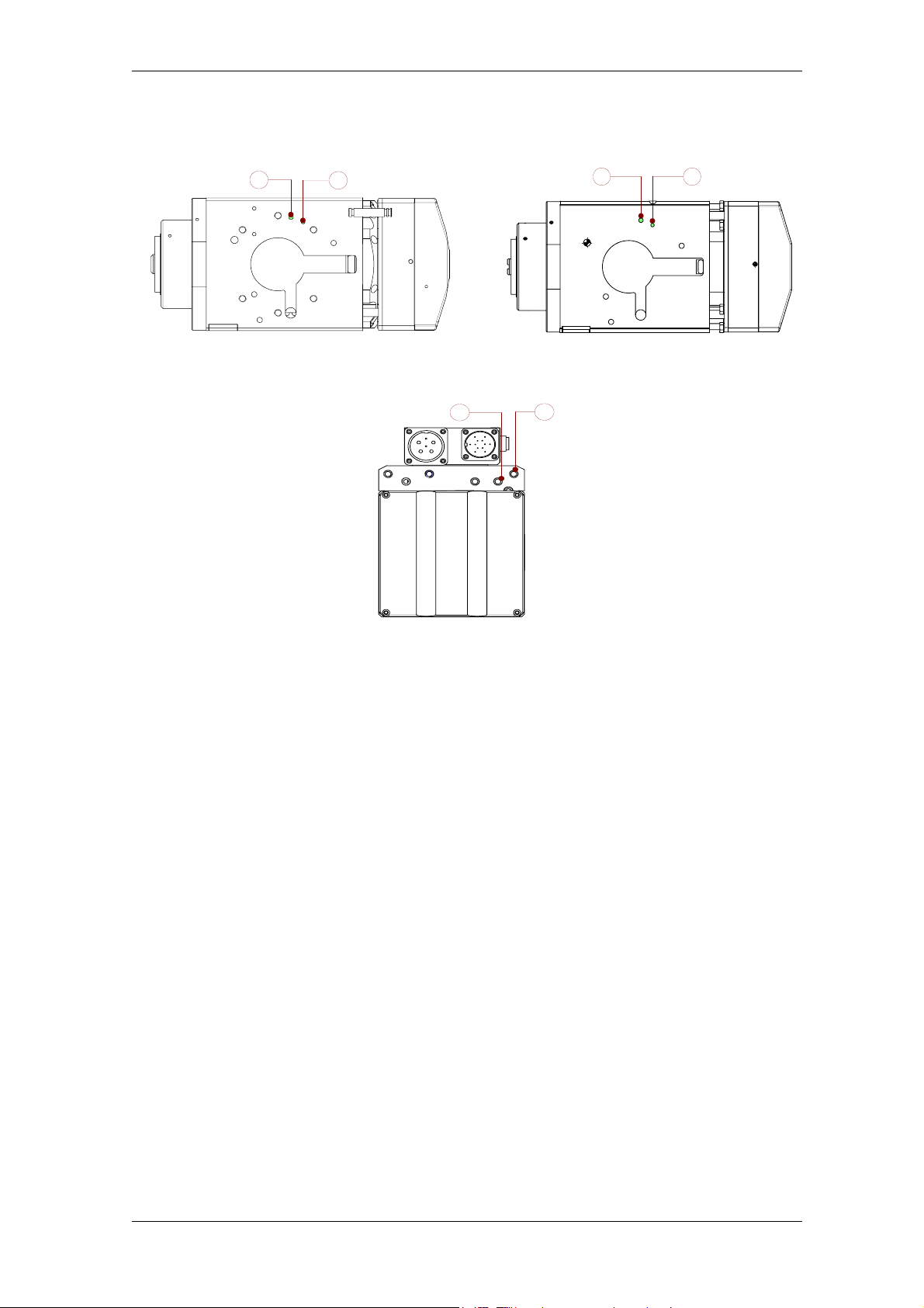
Figure 1 : pneumatic connection points
Ø 5
Ø 4
2
1
ø4
ø5
2 1
versions with “fixing bores”
versions with connectors
1
versions with “fixing grooves”
2
070-it_Cir-Pn.fm
HSD S.p.A.
44
Page 45
HSD
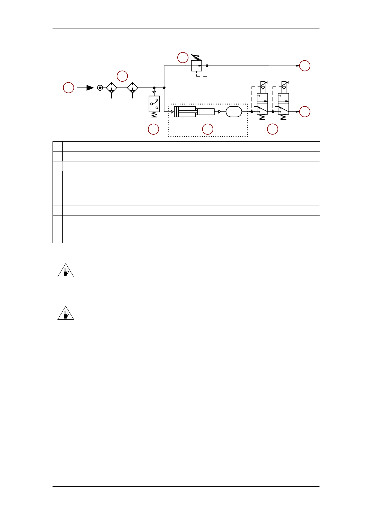
Figure 2 : indicative pneumatic layout
4
3
5
ø8/6mm
1
5 µ
0,1 µ
ø8/6mm
2
6
1 Air inlet for pressurisation and cone cleaning 4 bar (58 PSI)
2 Air inlet and outlet for tool holder unlocking 10 bar (145 PSI)
3 Line lead-in 10 bar (145 PSI)
Air filtration and purification stage for 99.97% at 0.1 µµm
4
(as an example: pair of condensate separation filters with automatic draining; first stage at 5
µµm and second at 0.1µµm, with a purification capacity of 99.97% at 0.1 µµm)
5 Pressure regulator set to 4 bar (58 PSI)
6 Pressure gauge
Pair of 3-way monostable solenoid valves
7
(use solenoid valves suitable for the pressures employed)
8 Possible pressure multiplication system
The use of two electric valves in series instead of just one reduces the
possibility of malfunctioning.
Although such malfunctioning is very rare, the seriousness sometimes means
the application of the redundancy principle.
8
7
THE CIRCUIT SHOWN IS PURELY INDICATIVE
070-it_Cir-Pn.fm
HSD S.p.A.
45
Page 46
HSD
IMPORTANT:
In order to guarantee the reliable function of the electrospindle, and in particular of the
precision bearings, it is absolutely essential to avoid the possibility of contamination of the dry
air circuit with oil from the lubricated air circuit (if installed) or from the compressor.
Keep the dry air circuit and lubricated air circuit completely separate and independent; where
this is not possible, take every measure necessary to prevent an abnormal flow-back of
lubricated air, for example using non-return valve upline of the oiler and tapping the dry air for
the electrospindle upline of these valves.
Purely as an example and not as a limitation we should point out that such back-flows may
cause fluctuations in pressure, for example during the starting and stopping phases of the
machine or compressor, or fluctuations in the mains voltage, faults in the compressor, etc.
4.6.2 Automatic cleaning of the tool holder cone
The tool holder cone and its tapered mounting on the spindle shaft is automatically cleaned by a jet
of compressed air during the tool changing phase.
This procedure protects the coupling surfaces against deposits of contaminants.
The state of the coupling surfaces must be checked at regular intervals, along with their level of
cleanliness, as described in section 7 “Scheduled maintenance”.
The jet of cleaning air is active for the whole time that the collet is open.
4.6.3 Internal pressurisation
The internal pressurisation prevents harmful particles from entering the electrospindle.
Pressurisation circuit must be fed with air compressed at the pressure indicated in Figure 2.
The pressurisation air must be present even when the electrospindle is at a
standstill and the machine is switched on, so that no dust from other
machining areas can come into the spindle.
With the spindle at standstill, check there is a uniform outlet of air around the spindle shaft
(pressurisation); if this is not the case, check the efficiency of the pneumatic circuit and the
tightness of the connections.
080-it_Tes-Pn.fm
HSD S.p.A.
46
Page 47
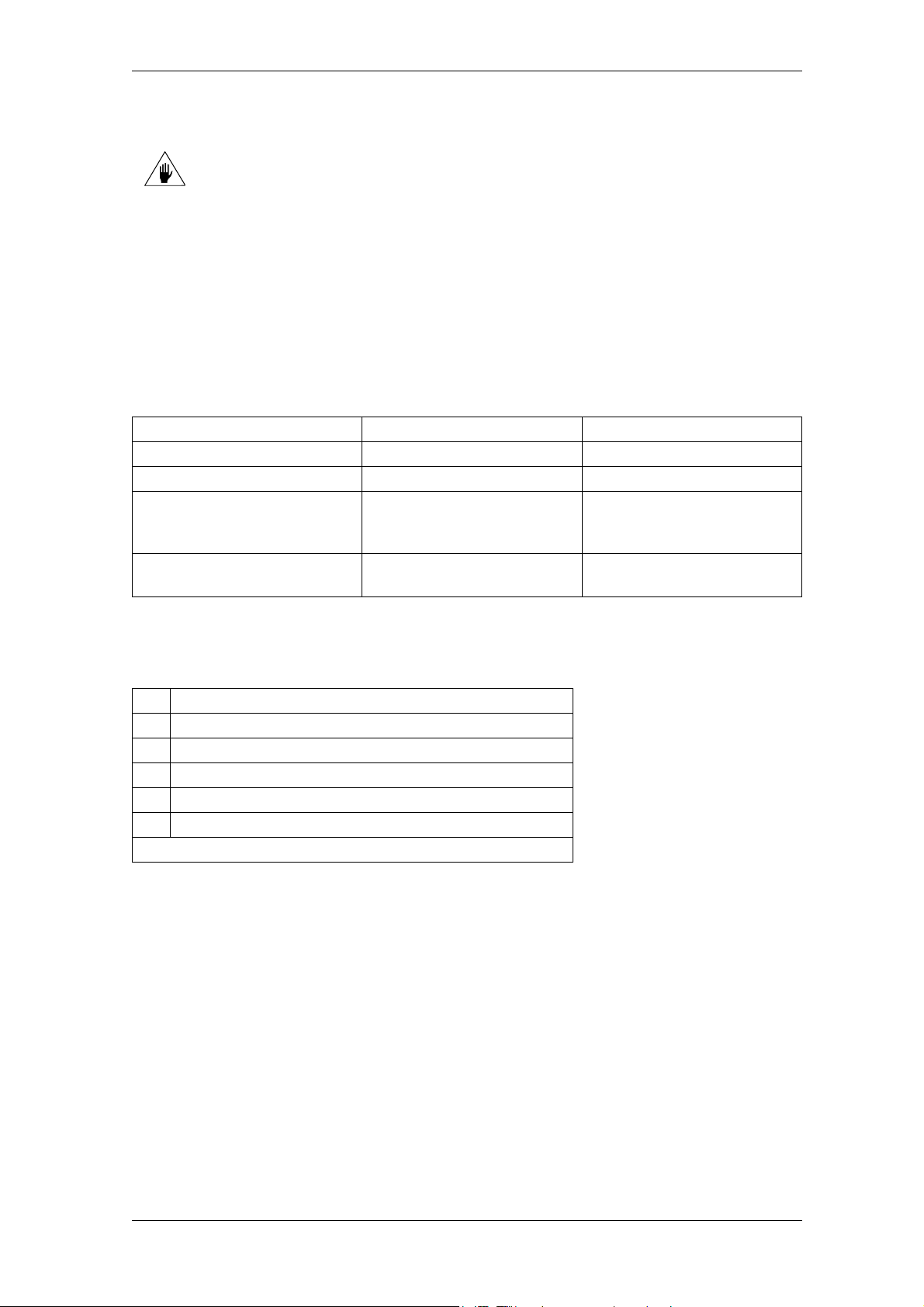
HSD
4.7 Hydraulic connections and specifications of the cooler
The gaskets that isolate the fluid circuits inside the electrospindle are made of NBR
(nitrile rubber): use only additives that do not degrade this material.
For the cooling circuit use water with 10% ethylene glycol and anticorrosion additives.
Upon request, HSD supplies “ARTIC-FLU-5” (order No.: H2161H0022).
ARTIC-FLU-5 is a premixed coolant ready for use, tested by HSD S.p.A.
It contains ethylene glycol and corrosion inhibitors with an ecological formula without amines,
nitrates or phosphates, and guarantees protection against corrosion for roughly 1 year.
ARTIC-FLU-5 prevents the formation of rust, scale and foam deposits, as well as the hardening,
cracking or swelling of the seals and sleeves.
It complies with various international standards, including CUNA NC 956-16.
4.7.1 Specifications of the cooler
Electrospindle power From 0 to 12 kW From 13 to 20
Cooling capacity 1,600 W 3,400 W
Minimum flow rate 5 litres/minute 5 litres/minute
Type of coolant
Temperature of the cooler
set
Water
+ 10% Ethylene Glycol +
corrosion inhibitors
+25+/-3°C (+77+/-5°F) +25+/-3°C (+77+/-5°F)
Water
+ 10% Ethylene Glycol +
corrosion inhibitors
4.7.2 Hydraulic connection points
The following figures illustrate the hydraulic connection points according to correspondence shown
in this table:
1 Engine coolant inlet
2 Engine coolant outlet
3 First lubricant-coolant inlet for tool
4 First lubricant-coolant outlet for tool
5 Second lubricant-coolant inlet for tool (*)
6 Second lubricant-coolant outlet for tool (*)
(*) present only in some versions.
090-it_Idr.fm
HSD S.p.A.
47
Page 48
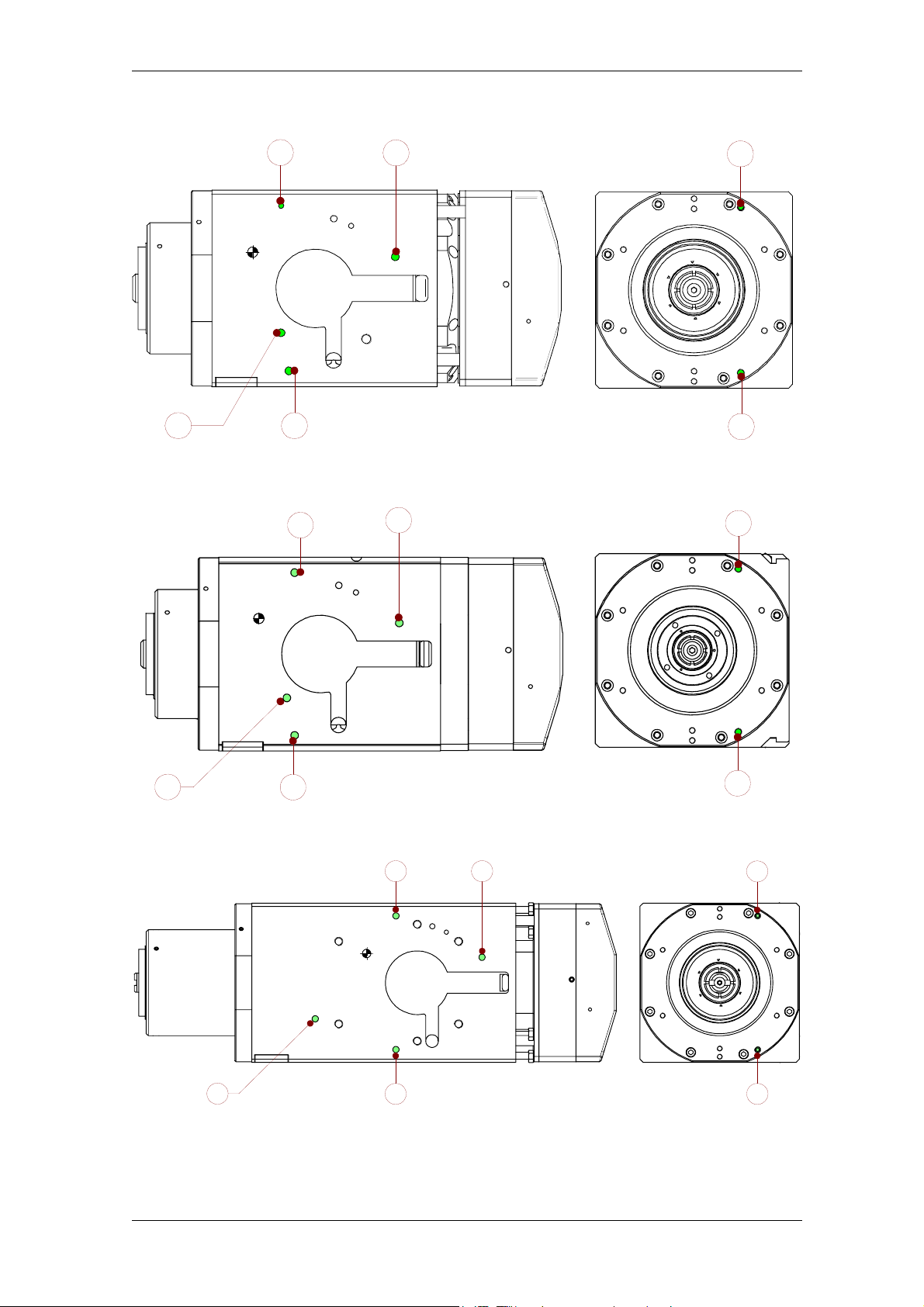
HSD
Figure 3 : hydraulic connections for ES779 with fixing bores
5
ø6
2
ø6
ø6
ø6
Figure 4 : hydraulic connections for ES779 with fixing grooves
31
2
ø6
5
ø6
6
M6
M6
4
6
M6
1
ø6
Figure 5 : hydraulic connections for ES789 with fixing bores
1
ø6 M6
090-it_Idr.fm
3
ø6
ø6
5 2
ø6
3
HSD S.p.A.
ø6
M6
4
M6
6
4
48
Page 49
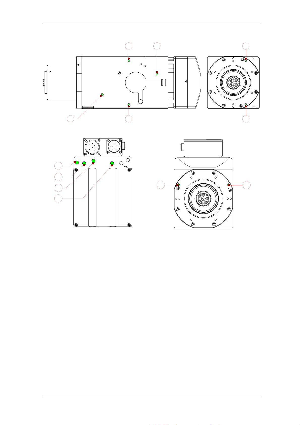
HSD
Figure 6 : hydraulic connections for ES789 with fixing grooves
ø6
5 2
1
ø6 M6
Figure 7 : hydraulic connections for all the other models with electrical connections
ø6
5
ø6
3
ø6
1
ø6
2
ø6
3
ø6
M6
4
M6
M6
6
4
4
090-it_Idr.fm
HSD S.p.A.
49
Page 50
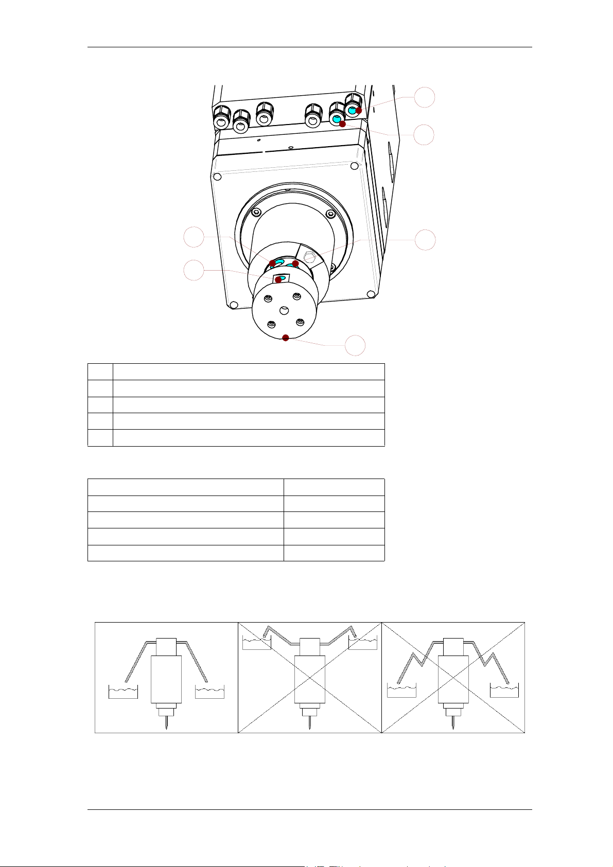
HSD
4.8 Pneumatic/hydraulic connections of models with distributor
1
2
3
5
4
1 Air inlet for tool changing (8x6 pipe 10 bar)
2 Air inlet for pressurisation (4x2 pipe 6 bar)
3 4 bores for safety drainage
4 Air inlet for tool cooling and cone cleaning (G1/8)
5 Tool coolant inlet; oil-water mix (G1/4)
Specifications of the distributor
Inlet air maximum pressure 20 bar
Inlet pressure drop 350 (NL/min)/1 bar
Filtration degree < 50 microns
Coolant inlet maximum pressure 80 bar
Dry running Possible
3
The cooling water reaches the tool through a fluid rotating distributor
Pipes connecting to distributor safety drainage must be oriented downwards. Pipes must remain
oriented downwards even when the machine moves the electrospindle (see the following figure).
090-it_Idr.fm
HSD S.p.A.
50
Page 51
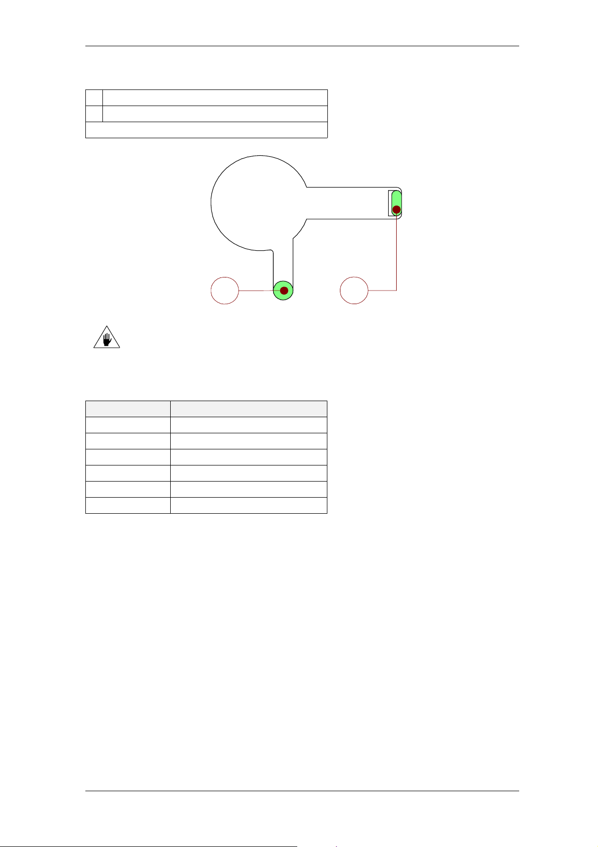
HSD
4.9 Electrical connections of models with free cables
1 Enconder and Sensor cable outlet (*)
2 Power and Thermal Alarm cable outlet
(*)The encoder is optional
1
The electrical power supply to the electrospindle MUST be provided via
inverter.
4.9.1 ES779 and ES789 Power Cables
Colour Description
Red U Motor Phase
Black V Motor phase
White W Motor Phase
Yellow/green : Motor Earth
Grey Thermal alarm
Grey Thermal alarm
2
100-it_Con-Elet.fm
HSD S.p.A.
51
Page 52
HSD
4.9.2 Sensor Cables (all motors)
Colour Description
White +24 V DC Sensor S1
Green 0 V Sensor S1
Brown OUTPUT Sensor S1
Yellow +24 V DC Sensor S2
Pink 0 V Sensor S2
Grey OUTPUT Sensor S2
Blue +24 V DC Sensor S3
Black 0 V Sensor S3
Red OUTPUT Sensor S3
(1)
Violet
Beige
Orange
(2)
(2)
+24 V DC Sensor S4
0 V Sensor S4
(2)
Sensor S4 OUTPUT
(1)
Only HSK versions:
weld “OUTPUT Sensor S1”
to the Brown conductor
(2)
Only HSK versions
(2)
(2)
Only HSK versions:
the welding specified in note “(1)” of the previous table connects S1 and S4 in series.
This eliminates the false signals of S4 in the phases when it is not important.
4.9.3 Encoder cables (Optional)
Colour Description
Brown B +
Blue B Yellow A +
Green A Black 0V
Grey Z +
Red Vcc (*)
White Z -
(*) +5 V DC or +12 V DC according to model
Check power supply voltage of the Encoder model before connecting and feeding it
so as not to damage electronic circuits.
100-it_Con-Elet.fm
The cables of the Sensors and Encoder ARE NOT “high-flexibility” ones.
If the application requires it, use “high-flexibility” cables for the connections.
HSD S.p.A.
52
Page 53
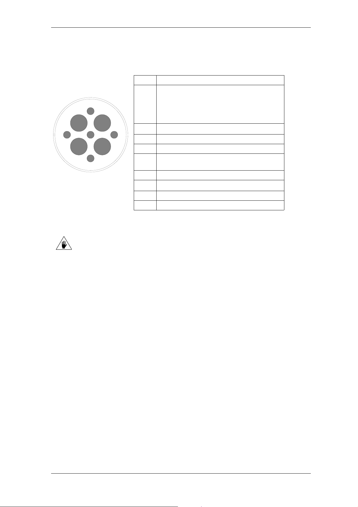
HSD
4.10 Electrical connections of models with HSD connectors
4.10.1 Power connector diagram
PIN DESCRIPTION
THERMAL PROTECTIVE DEVICE:
bimetallic normally-closed (NC) switch to be
1
1
2
8
9
3
4
7
6
5
connected in series to the machine alarm or
the inverter alarm.
48V DC MAX; 1.6A MAX
2
PE
: in common with PIN 7
3 not used
4 Motor U phase
THERMAL PROTECTIVE DEVICE (see PIN
5
1)
6 Motor V phase
7
PE
: in common with PIN 2
8 Motor W phase
9 Not used
Use cables of not less than 6 mm
2
1 mm
minimum (or at least AWG18) for the odd ones
2
(or at least AWG10) for the even PINS, and
100-it_Con-Elet.fm
HSD S.p.A.
53
Page 54
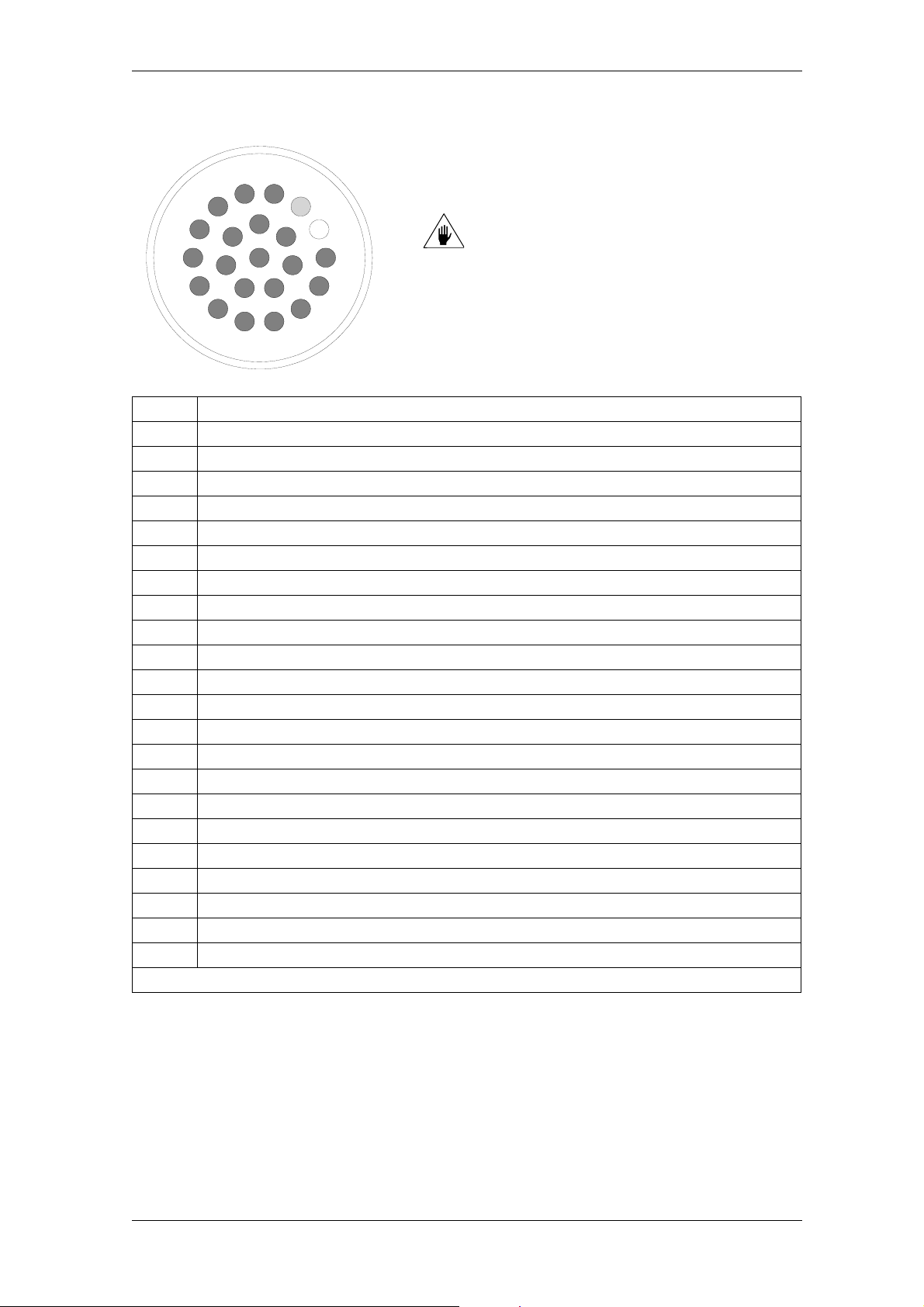
HSD
4.10.2 Signal connector diagram
1
16
7
15
22
14
21
19
8
13
20
9
12
10
Use cables of not less than 0.35
mm
11
2
3
4
17
18
5
6
PIN DESCRIPTION
1 sensor S2 (collet open) OUTPUT
2 S1+ S4 sensor series (tool locked) OUTPUT
3 S3 sensor (stopped shaft) OUTPUT (S3 optional)
4 +24V DC power to S1, S2, S3
5 +24V DC power to push-button LIGHT BULB
6 0V power supply to S1, S2, S3
7 +24V DC power supply to BUTTON
8 PUSH-BUTTON OUTPUT
9 Not used
10 Not used
11 0V power supply to BUTTON and LIGHT BULB
12 Not used
13 Not used
14 S1 sensor (tool present) OUTPUT
15 A + (ENCODER optional)
16 A - (ENCODER optional)
17 B - (ENCODER optional)
18 0V (optional ENCODER power supply)
19 Z + (ENCODER optional)
20 VCC (optional ENCODER power supply)
21 B + (ENCODER optional)
22 Z - (ENCODER optional)
(*) +5 V DC or +12 V DC according to model
2
(or at least AWG22)
100-it_Con-Elet.fm
HSD S.p.A.
54
Page 55
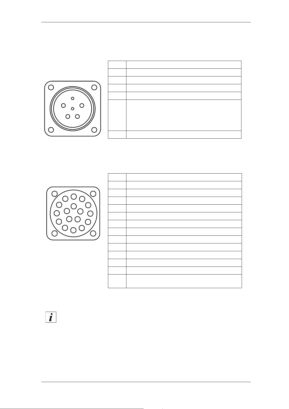
HSD
4.11 Electrical connections of models with military connectors
4.11.1 Power connector diagram (standard MIL)
PIN DESCRIPTION
A U Motor phase
B V Motor phase
C W Motor phase
E
D
C
A
F
B
D U Motor phase
THERMAL PROTECTIVE DEVICE:
bimetallic normally-closed (NC) switch to be
E
connected in series to the machine alarm or the
inverter alarm.
48V DC MAX; 1.6A MAX
F THERMAL PROTECTIVE DEVICE (see PIN E)
4.11.2 Signal connector diagram (standard MIL)
PIN DESCRIPTION
A sensor S2 (collet open) OUTPUT
A
M
L
T
K
S
J
H
G
B
N
R
C
P
D
E
F
B S1+ S4 sensor series (tool locked) OUTPUT
C S3 sensor (stopped shaft) OUTPUT (S3 optional)
D +24V DC power to S1, S2, S3
E +24V DC power to push-button LIGHT BULB
F 0V power supply S1, S2, S3, S4
G +24V DC power supply to BUTTON
H PUSH-BUTTON OUTPUT
J 0V power to BUTTON and LIGHT BULB
M S1 sensor (tool insert) OUTPUT
N THERMAL PROTECTIVE DEVICE
P THERMAL PROTECTIVE DEVICE
K-L
O,P-T
Not used
100-it_Con-Elet.fm
Contacts of the thermal probe can be found in the power connector or in the
signals connector according to the electrospindle model.
For the correct pin-out of connectors, see the dimensional drawing of the
spindle concerned
HSD S.p.A.
55
Page 56
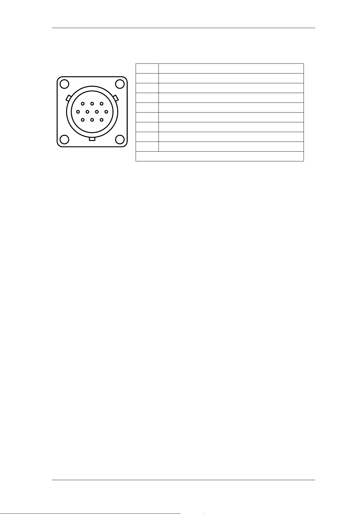
HSD
4.11.3 Encoder connector diagram
PIN DESCRIPTION
A A +
B A -
H
KJ
G
F
A
B
C
DE
C B -
D 0V power to ENCODER
E Z +
F VCC ENCODER power supply (*)
J B +
K Z -
(*) +5 V DC or +12 V DC according to model
100-it_Con-Elet.fm
HSD S.p.A.
56
Page 57
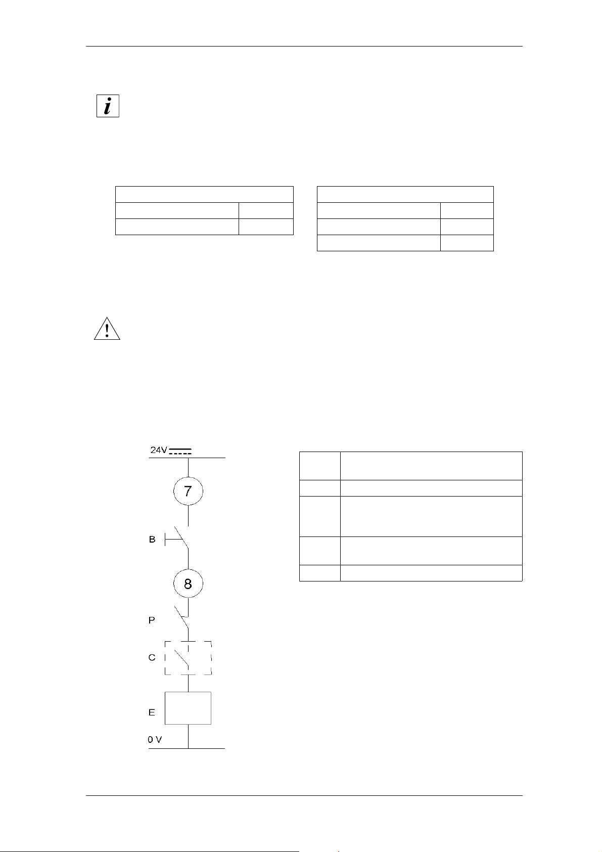
HSD
4.12 Tool release button
The position of the button is shown in section 3.1
The button on the electrospindle can be used to manually command the release of the tool holder:
so that by keeping the button pressed the tool is expelled and the collet remains open until the
button is released again.
Characteristics of the button Bulb characteristics
Rated voltage (DC) 24V Rated voltage (DC) 24V
Maximum current 100 mA Rated power 0.7W
Rated current 29 mA
4.12.1 Electric diagram for manual tool holder release
When the spindle is rotating, a control system must disable the command arriving
from the button.
The activation of the button must only be possible with the spindle idle.
The tool locking/release operation via this button must only be carried out with
the machine in MANUAL working mode (not AUTOMATIC).
The tool could be ejected at high speed if the safety conditions described above
are not respected.
7 - 8
PINS 7 and 8 of the SIGNALS
connector
B Tool release button
Pressure switch that, in the event of
P
low pressure, does not allow the
release of the tool holder
Safety check
C
(zero speed device)
E CNC
100-it_Con-Elet.fm
HSD S.p.A.
57
Page 58

HSD
5 General checks after installation
5 General checks after installation
5.1 Checks before the start-up
5.1.1 Pneumatic circuit
Pneumatic circuit pipes must have the diameter specified in section 4.6 “Pneumatic
connections”. Input compressed, dry and filtered air, according to the specifications indicated
in the same section;
for the connections, check any labels on the product and refer to section 4.6 “Pneumatic
connections”;
compressed air must always be present, even when the electrospindle is stopped: check (with
the electrospindle stopped and tool holder installed) that a uniform and continuous flow of air
comes out from the labyrinth on the spindle nose;
the cone cleaning air must be present during tool changing;
The expulsion progress of the tool-holder cone must be that indicated in section 6.4 “Tool
holder locking and ejection device”.
5.1.2 Hydraulic circuit
The liquids used must respect the specifications and warnings in section 4.7 “Hydraulic
connections and specifications of the cooler”.
5.1.3 Electrical circuit
The earthed cable of the product (indicated in section 4.8 and 4.10) must be
connected to the earthed cable of the machine;
the thermal safety switch must activate a procedure for protecting against the
overheating of the coils of the electrospindle (see section 6.6.4).
5.1.4 Programming the inverter
The maximum voltage set on the inverter must correspond to the rated value indicated on the
motor rating plate.
The set frequency value at which the maximum voltage (rated frequency) is to be attained
must correspond to the value indicated on the motor rating plate.
The maximum speed set on the inverter must correspond to the value indicated on the motor
rating plate.
The maximum direct current supplied to the inverter must correspond to the rated current
indicated on the motor rating plate.
If it is considered necessary to check the other parameters of the inverter, please contact HSD
S.p.A.
140-it_1-Avv.fm (19-01-09)
HSD S.p.A.
58
Page 59
HSD
5 General checks after installation
5.2 Checks during initial starting
Start the electrospindle only if the sensors confirm the following conditions
simultaneously:
Sensor 1 ON Tool-holder cone attached
Sensor 1 + Sensor 4 (*) ON (*) HSK cone blocked in the correct position (*)
Sensor 2 OFF Collet closed
(*) HSK versions only
The “ON” condition of the sensor corresponds to the output equal to the
supply voltage.
The “OFF” condition of the sensor corresponds to an output of 0V.
It is forbidden to start the electrospindle without the tool holder installed.
the control sensors must intervene according to the logic described in section 6.6;
the tool changing cycle may only start when the shaft is at a standstill;
with the tool holder inserted, and without machining, carry out the preheating cycle described
in section 6.3.
140-it_1-Avv.fm (19-01-09)
HSD S.p.A.
59
Page 60

HSD
6 Use and Adjustment
6 Use and Adjustment
6.1 Environmental Conditions
HSD S.p.A. has inspected and tested its products in accordance with standard environmental
conditions(CEI EN 60034-1:2006-05). Contact HSD S.p.A. for information on the possibility of
applications in special environments.
6.2 Running-in
Before being packed, the product was subjected to an automatic running-in cycle to guarantee the
correct distribution of the lubricant (long-life grease) on the races of the bearings, and to run in the
spheres and races of the bearings themselves. If present, also the reducers and servomotors are
run in, and dynamic tests are carried out on the inner pneumatic and hydraulic circuits.
The running-in cycle also includes a strict inspection of all the command and signalling elements,
simulating various types of operating cycle on the test bench.
6.3 Preheating
HSD S.p.A. uses high-precision angular contact bearing pairs, pre-loaded and lubricated for life
with special grease for high speeds.
When the machine is switched on for the first time every day, allow the electrospindle to perform a
brief preheating cycle in order to allow the bearings to gradually attain a uniform operating
temperature, and hence to obtain a uniform expansion of the bearing races and the correct preload
and rigidity.
The following cycle is recommended, with tool holder inserted, but without machining
operations:
50% of the maximum rated speed for 2 minutes.
75% of the maximum rated speed for 2 minutes.
100% of the maximum rated speed for 1 minute.
The preheating cycle should also be performed every time that the machine is
inoperative long enough for the electrospindle to cool down to room temperature.
Only in cases of the first start-up after storage or machine shutdown for more than
four months, allow the machine to run for 2 minutes at 5,000 rpm before proceeding
with the preheating cycle.
While the machine is operating, the spindle can reach high temperatures. Be
very careful not to touch it without due precautions.
150-it_Run-In.fm (19-01-09)
HSD S.p.A.
60
Page 61
HSD
6.4 Tool holder locking and ejection device
The blocking and expulsion of the tool-holder are achieved by the double-acting movement of a
pneumatic piston, activated with compressed air of the pressure indicated in section 4.6
“Pneumatic connections”.
The tool-holder cone expulsion must be around 0.5 mm - 0.9 mm for versions ISO and around 0.5
mm - 0.6 mm for versions HSK.
The tool-holder is blocked mechanically by elastic springs that develop an axial force equal to:
ELECTROSPINDLE
MODEL
ES779 HSK E40-F50 2,300 ± 10% 6,800 ± 10%
ES779 HSK A/E 63 6,300 ± 10% 18,000 ± 10%
ES779 HSK F63 3,430 ± 10% 11,000 ± 10%
ES789 HSK F63 3,430 ± 10% 11,000 ± 10%
The axial force exerted on the tool-holder by the blocking system is guaranteed
constant for a minimum duration of 2,000,000 cycles of tool change
1 tool changing cycle = tool blocked / tool released / tool blocked
All HSD electrospindles have a mechanical reaction system that neutralises the
axial force of the piston on the shaft during the tool changing phase, thus
guaranteeing the integrity of the precision bearings.
AXIAL FORCE
OF THE SPRINGS
AXIAL FORCE ON
TOOL HOLDER
160-it_Aggancio.fm (19-01-09)
HSD S.p.A.
61
Page 62

HSD
6.4.1 Tool holder cone
CONE ISO30
DIN69871
The geometry of the conicity must respect standard DIN69871 for ISO30 cones, and standard
DIN69893 for HSK cones.
The tool holder cone ISO30 must have an AT3 precision rating;
Avoid the presence of plugs, slots, or other forms affecting the dynamic balancing of the tool
holder;
At the maximum rated speed of the electrospindle, the level of dynamic balancing must be G =
2.5 or better (ISO1940 standard);
The balancing must be carried out with the tool holder assembled (cone, mill collet, ring nut,
tool);
The tie-rod (also known as the shank) of the cone ISO30 must only be the one supplied by
HSD (code 0804H0009).
TIE-ROD HSD
0804H0009
HSK CONE
DIN69893
6.4.2 Installation of the tie-rod HSD 0804H0009 in the cone ISO30 DIN69871
• Carefully clean the tie-rod and the tie-rod housing in the cone ISO30.
• Cover the thread of the tie-rod with high resistance, thread-blocking liquid (LOCTITE 270 or
another equivalent
• Tighten the tie-rod to the cone with a torque of 62 Nm.
• Leave the cone to rest, to allow the thread-blocking liquid to adhere (12 hours with LOCTITE
270, or depending on the manufacturer's indications if using an alternative, equivalent
thread-blocker).
The use of non-original HSD tie-rods, or incorrect installation, may cause the
tool holder cone to be thrown out.
product).
It is forbidden to use ISO or HSK tool holders not conforming to the
conditions described above; failure to observe these instructions
represents a source of risk, damage or incorrect hooking of the tool
holder cone, with serious risks for the user.
160-it_Aggancio.fm (19-01-09)
HSD S.p.A.
62
Page 63

HSD
6.4.3 General recommendations relating to tool holder cones
IMPORTANT:
The choice of tool holder is a determining factor for safety purposes.
The conical surfaces of the tool holder and of its housing on the shaft/spindle must be kept
thoroughly clean in order to permit secure mounting (see section 7 “Scheduled maintenance”).
During machining operations, be sure to avoid any contact between the non-cutting rotating
parts and the piece being machined.
The seat of the tool holder cone must always be protected against any impurity that may come
in: use a closing device or a tool holder cone.
At the end of the working day, always remove the tool holder cone from the electrospindle, to
avoid any problem of it sticking. Close the seat of the tool holder by means of a tool holder
cone that is clean and at room temperature.
Do not set the electrospindle in rotation without the tool holder installed. In particular, for the
HSK models, the rotation of the electrospindle without its tool holder jeopardises the balancing
and the working of the collet.
6.5 Tool
The tools must have a degree of dynamic balancing of G = 2.5 or better (standard ISO1940).
OBSERVE THE MAXIMUM ROTATIONAL SPEED (rpm) SPECIFIED BY THE
TOOL MANUFACTURER.
Depending on the type and quality of the machining operation to be performed and the material
used, it is the responsibility of the user to decide whether to operate with a lower speed (NEVER
HIGHER) than that specified by the tool manufacturer.
When selecting the tool, it is essential to pay attention to the following recommendations:
Always use properly sharpened tools, locking them correctly in the respective tool holder.
Never use deformed or damaged tools, tools with missing parts or tools that are not perfectly
balanced.
Before inserting the tool in the respective collet, always check that all the surfaces are free
from damage and thoroughly cleaned.
The essential conditions for using a tool at high speed are:
- compact, short and light tool
- accurate and with some blocked inserts with a high safety degree
- balanced and symmetrically coupled with the tool holder
- with cutting edges near the rotation axis
170-it_Racco-Ut.fm (19-01-09)
HSD S.p.A.
63
Page 64

HSD
6.5.1 Speed limits regarding the tool
As an example, the charts on the following pages show the maximum rotation speed of the
electrospindle when empty, on the basis of the weight of the TOOL+TOOL HOLDER assembly
(including ring nut and mill collet if present), and, furthermore, depending on the distance between
the nose of the electrospindle and the centre of gravity “G” of the tool+tool holder assembly.
Next to each chart there is the tool+tool holder assembly that was envisaged as assembled in the
spindle shaft to calculate the curves.
The mass of the tool+tool holder assembly was applied to the centre of gravity “G”, highlighted in
the drawing.
Some possible positions of the centre of gravity “G” were considered, and for each position a curve
has been drawn on the chart.
The degree of balancing is that recommended in the previous paragraphs.
The charts on the following pages are approximate, i.e. they do not take into account (because
HSD S.p.A. cannot know this piece of information) the machining operation parameters, the
specific characteristics of the tool used by the customer, or the particular type of material being
machined: it is the user's responsibility to evaluate each time the maximum speed that allows him
to work safely.
Procedure for reading the charts
5. Identify the chart relating to your electrospindle;
6. On the basis of the distance “X” between the spindle nose and the centre of gravity “G” of the
tool+tool holder assembly, choose one of the curves. If the “X” measured on your
electrospindle does not appear on the chart, choose the curve associated with the “X” that is
the next measurement bigger (see example);
7. Corresponding to the weight of the tool+tool holder assembly, read the value of the maximum
speed.
EXAMPLE
On an ES789 HSK a tool+tool holder assembly with an overall weight of 4.5 kg (including the ring
nut and mill collet) is to be used; the distance between the spindle nose and the centre of gravity
“G” of the tool+tool holder assembly is “X”=120 mm:
1. The chart relating to this particular electrospindle is “ES789 HSK” on page 66;
2. With no specific curve for “X”=120 mm, it is necessary to refer to the yellow curve associated
with “X”=130 mm;
3. Corresponding to the weight of 4.5 kg, you can read the maximum speed, when empty, of
10,000 rpm.
180-it_Max-rpm.fm (19-01-09)
HSD S.p.A.
64
Page 65
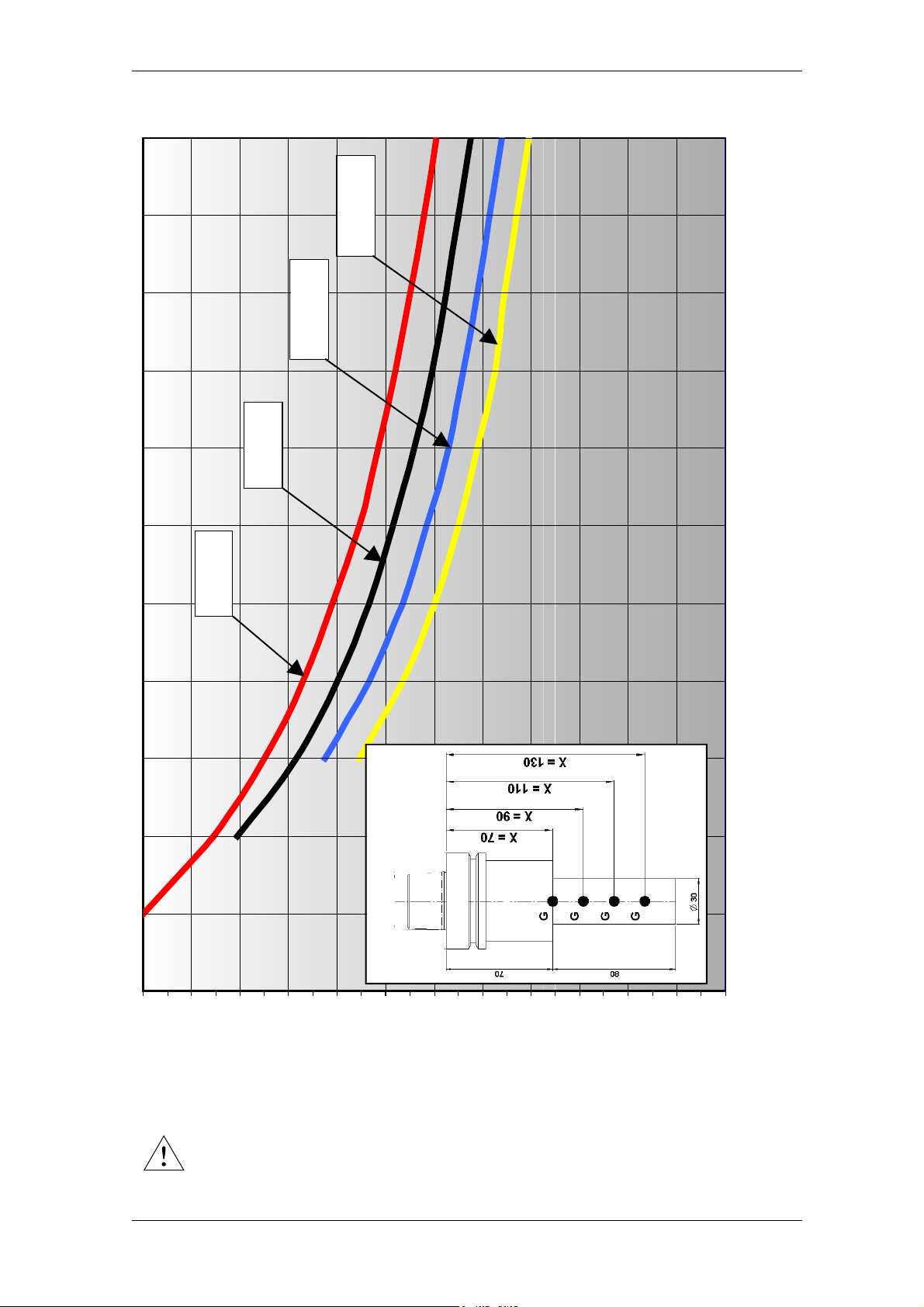
HSD
p
ES779 HSK Short Nose
X = 110
X = 90
X = 130
X = 70
Kg
0 1 1,5 2 2,5 3 3,5 4 4,5 5 5,5 6
0
24000
.
180-it_Max-rpm.fm (19-01-09)
22000
20000
DO NOT EXCEED THE MAXIMUM ROTATIONAL SPEED (rpm) SPECIFIED BY
THE TOOL MANUFACTURER!
18000
16000
14000
m
12000
HSD S.p.A.
10000
8000
6000
4000
2000
65
Page 66
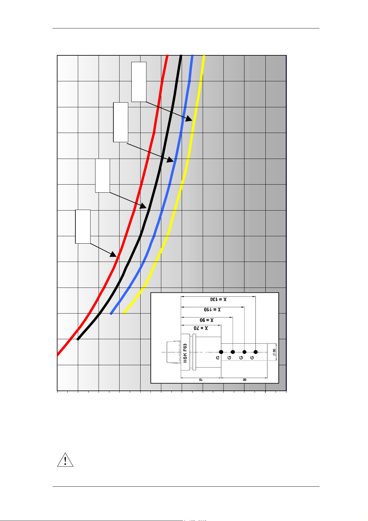
HSD
7
ES789 HSK
X = 130
X = 70
X = 110
X = 90
Kg
22000
.
180-it_Max-rpm.fm (19-01-09)
20000
DO NOT EXCEED THE MAXIMUM ROTATIONAL SPEED (rpm) SPECIFIED BY
THE TOOL MANUFACTURER!
18000
16000
14000
12000
pm
HSD S.p.A.
10000
8000
6000
4000
0 1 1,5 2 2,5 3 3,5 4 4,5 5 5,5 6 6,5
0
2000
66
Page 67
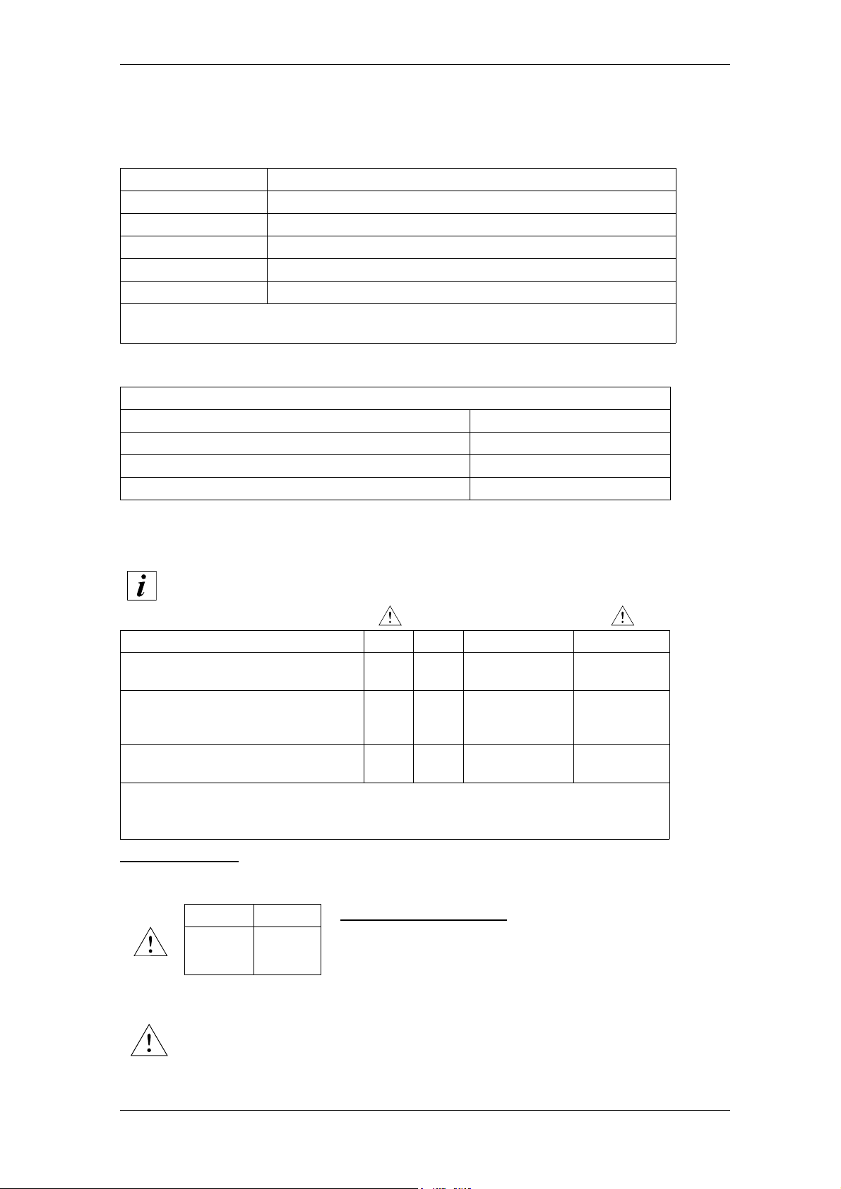
HSD
6.6 Sensors
The electrospindle is equipped with inductive sensors for monitoring its status, and a “thermal
alarm” to protect the electric coils.
NAME INFORMATION OF THE SIGNAL
S1 Tool holder cone attached
S2 Collet open - Tool released
S3 (*) Shaft idle (*)
S1+S4 (**) HSK cone blocked in the correct position (**)
Thermal alarm Motor overheated: stop the electrospindle!
(*) Not present in some versions
(**) Only in HSK versions
6.6.1 Technical characteristics of the inductive sensors
Proximity sensors PNP normally open (NO)
Supply voltage 10 - 30V (DC)
Maximum load 200 mA
Power consumption when OFF <10 mA
Nominal detection distance 0.8 mm
6.6.2 States of the electrospindle and corresponding outputs of the inductive sensors
The “ON” condition of the sensor corresponds to the output equal to the
supply voltage; the “OFF” condition corresponds to an output of 0V.
STATE S1 S2 S3 (*) S1+S4 (**)
Collet open
(Tool-holder cone ejected)
Tool holder cone
correctly locked
Collet closed but tool holder cone
missing
(*) Not present in some versions
(**) HSK versions only
(***) Depending on the operating status of the machine
For HSK versions there is one further status of the electrospindle, in which the tool-holder cone
is attached, but not correctly positioned on the stop as regards the surface of the HSK hooking
system. This situation is indicated by the output:
S1 S1+S4
ON OFF
OFF ON IDLE OFF
IDLE or
ON OFF
OFF OFF IDLE OFF
This condition is dangerous:
if it arises, stop the rotation or the tool change procedure, check the
machine and remove whatever is preventing the correct hooking-up
of the HSK tool-holder.
STARTED UP
(***)
ON
The shaft of the electrospindle can only be rotated in the “Tool holder cone
correctly locked” status; if the outputs of S1 or S1+S4 move to “OFF”, stop the
rotation of the shaft of the electrospindle.
190-it_Uso-Sens.fm (19-01-09)
HSD S.p.A.
67
Page 68
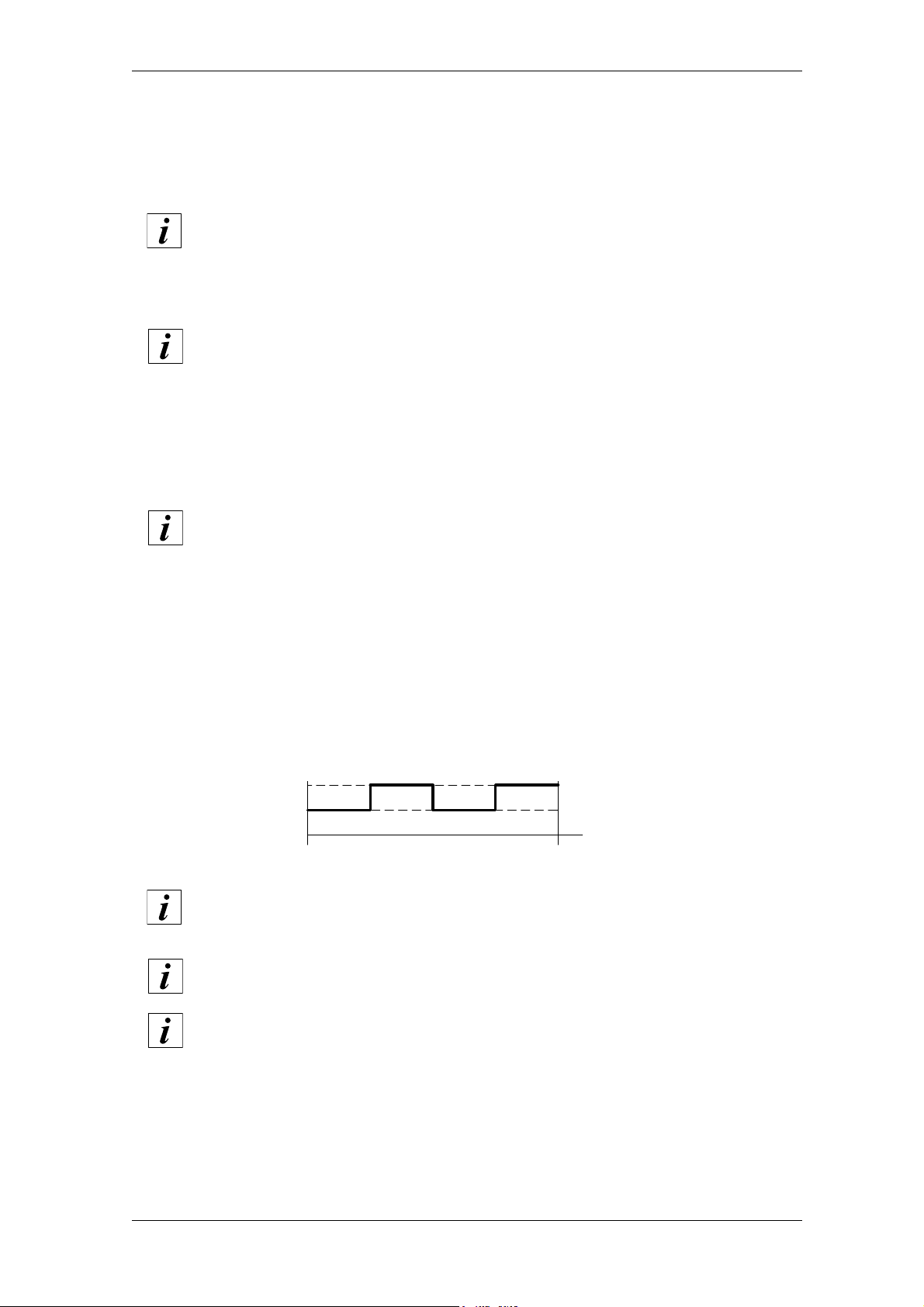
HSD
6.6.3 Description of the inductive sensors
Sensor S1: “Tool holder attached” signal
The signal of sensor S1 indicates the presence of the tool holder cone in the closed collet.
Ignore output S1 during the period from the tool release command to the tool
hooking command.
Sensors S1+S4: “HSK cone blocked in correct position” signal
The S1+S4 signal is present only in HSK versions.
Sensors S1 and S4 are connected in sequence (section 8.3.3).
Sensor S1 checks that the HSK tool holder cone is present in the closed collet, then activates the
reading of sensor S4.
If activated by S1, S4 checks that the stop surfaces of the tool holder cone and the HSK hooking
system are correctly in contact.
The output is “ON” only if both conditions have been checked.
Ignore the output of S1+S4 during the period from the tool release command to
the tool hooking command.
Sensor S2: “Collet open” signal
Signal S2 is relevant during the tool changing cycle: it signals the opening of the collet and the
possibility to continue to the next phase of the tool change cycle.
Sensor S3: “Shaft idle” signal
Sensor S3 supplies two “ON” pulses and two “OFF” pulses at each rotation of the shaft, as shown
in the figure below.
ON
OFF
0
giri - rev
Above a certain rotation speed, the output of S3 may appear to be permanently
“ON”, only returning to a regular status when the speed drops below this
threshold. This phenomenon is not a malfunction and depends on the
performance of the CNC.
Ignore the signal S3 during the tool changing phase, as it may appear to be in
either of the two statuses (“ON” or “OFF”)
1
The S3 signal is not present in certain versions.
190-it_Uso-Sens.fm (19-01-09)
HSD S.p.A.
68
Page 69

HSD
6.6.4 Use and technical characteristics of the thermal alarm
The electrospindle is equipped with a normally closed bimetallic switch installed in the electric
windings of the stator. If a temperature is reached that is harmful for the electric windings, the
switch open and the alarm to which it is connected must stop the machining operation; the contact
closes automatically when the temperature drops and returns to safe values.
The bimetallic switch must be connected to the machine alarm or the inverter alarm, as shown in
section 4.9.
Technical characteristics of the bimetallic switch:
Power supply 48V DC MAX
Current 1.6A MAX
Switching cycles 10,000 cycles
Contact breaking time < 1 ms
Contact resistance (according to MIL R 5757) < 50mΩ
Insulation voltage 2 kV
190-it_Uso-Sens.fm (19-01-09)
HSD S.p.A.
69
Page 70

HSD
6.7 Encoder (optional)
6.7.1 General description
The encoder codes in an incremental system the registered position data with A and B, A negated
and B negated signals, in phase quadrature; it also provides Zero and Zero negated signals (see
following figures
).Signals are taken outside as shown in section 4.9.3 “Encoder cables (Optional)”.
There are three models of encoder available:
HSD “Square Wave” type;
Lenord+Bauer “Square Wave” type;
Lenord+Bauer “Sinusoidal” type.
200-it_Encoder.fm (19-01-09)
HSD S.p.A.
70
Page 71
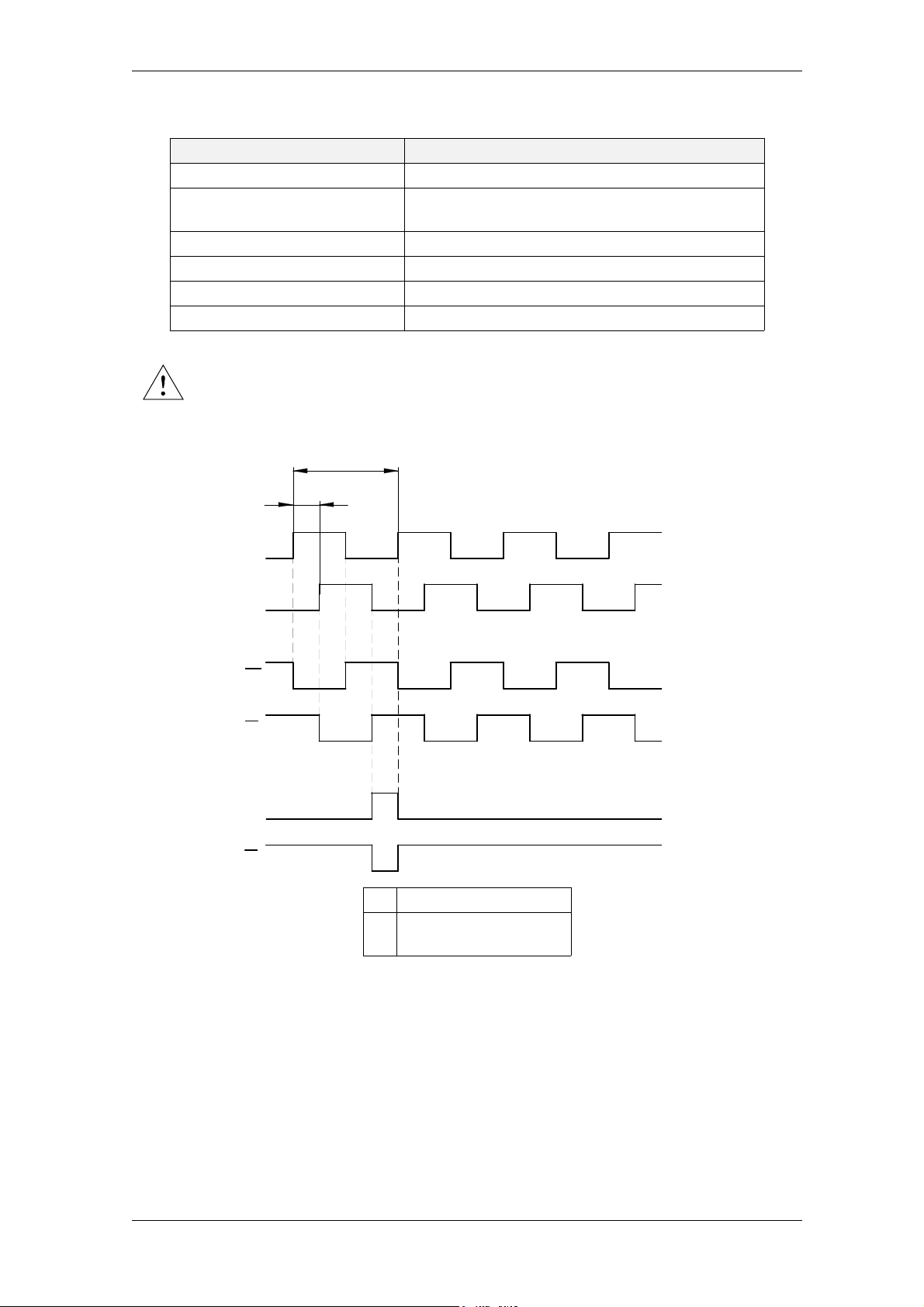
HSD
6.7.2 Technical specifications of the HSD Square Wave encoder
SPECIFICATION VALUE
Rated supply voltage 12 V DC ÷ 24 V DC +/- 10%
Consumption
Operating temperature 0° C ÷ 70° C (+32° F ÷ 158° F)
Max. operating height 2,000 m (6,500 ft)
Signal input: 400 pulses per rev + zero reference
Signal output: TTL-level compatible (0V, +5V line driver)
A voltage over the specified (24V ±10%) may damage the encoder reader
Signals of the HSD Square Wave encoder
T
D
99 mA at 12 V DC
51 mA at 24 V DC
A
B
A
B
Z
Z
T Period
D Phase Difference
(D=T/4)
5 V
0 V
5 V
0 V
5 V
5 V
0 V
0 V
5 V
5 V
0 V
0 V
5 V
5 V
0 V
0 V
5 V
5 V
0 V
0 V
200-it_Encoder.fm (19-01-09)
HSD S.p.A.
71
Page 72
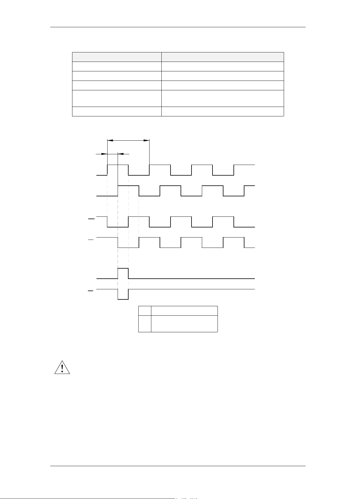
HSD
6.7.3 Technical specifications of the Lenord+Bauer Square Wave encoder
SPECIFICATION VALUE
Rated supply voltage 5 V DC +/- 5%
Operating temperature -30° C ÷ +85° C (-22° F ÷ +185° F)
Max. operating height 2,000 m (6,500 ft)
Signal input:
Signal output: TTL-level compatible (0V, +5V line driver)
Signals of the Lenord+Bauer Square Wave encoder
T
D
A
B
1024 pulses per rev + zero reference
(256 pulses multiplied x4 internally)
5 V
0 V
5 V
0 V
5 V
A
B
Z
Z
T Period
D Phase Difference
(D=T/4)
A voltage over the specified value (5V ±5%) may damage the encoder reader
0 V
5 V
0 V
5 V
0 V
5 V
0 V
200-it_Encoder.fm (19-01-09)
HSD S.p.A.
72
Page 73
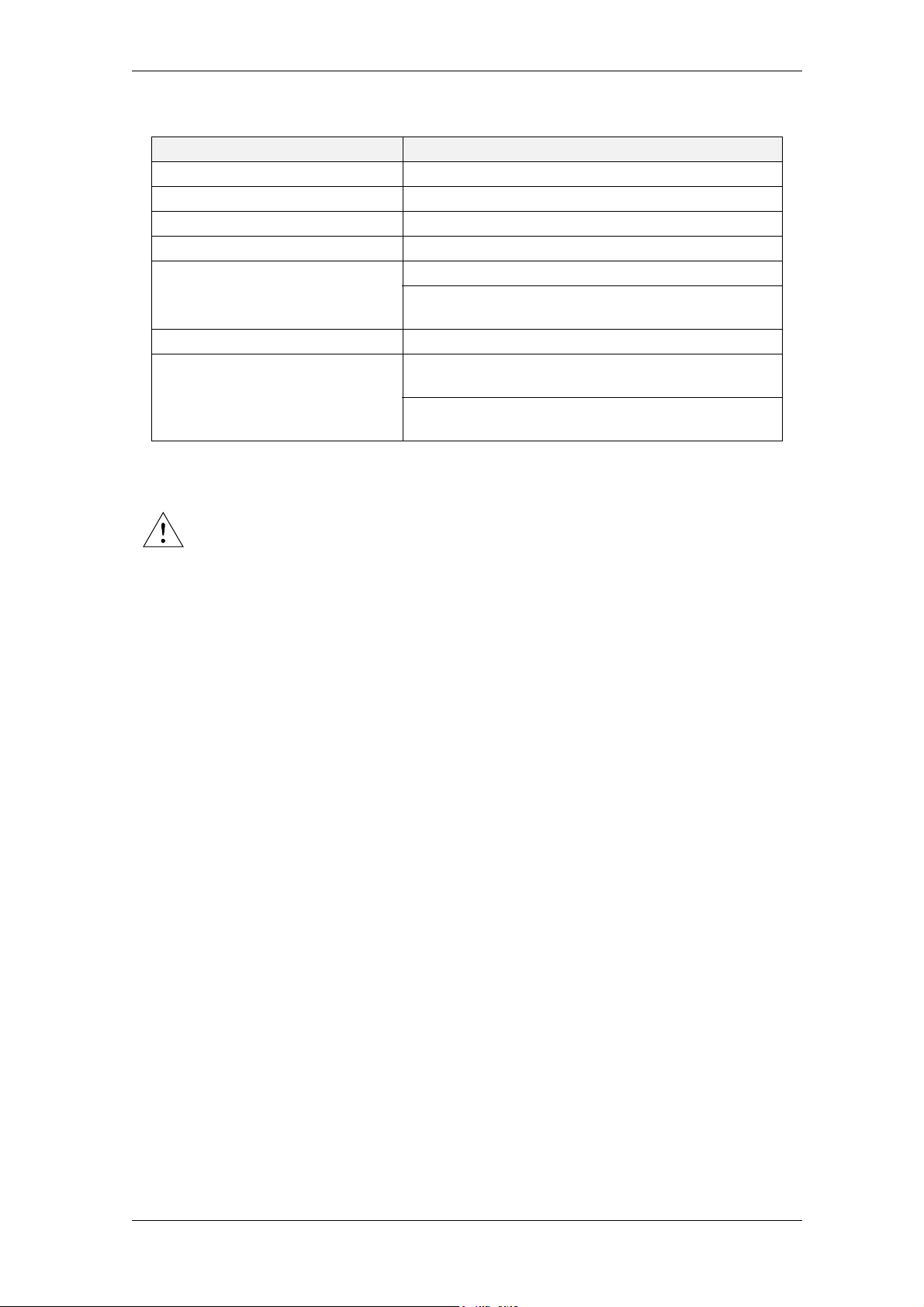
HSD
6.7.4 Technical specifications of the Lenord+Bauer Sinus Wave encoder
SPECIFICATION VAL U E
“U” rated supply voltage 5 V DC +/- 5%
Operating temperature -30° C ÷ 85° C (-22° F ÷ 185° F)
Max. operating height 2,000 m (6,500 ft)
Signal input: 256 pulses per rev + zero reference
500 mV peak-to-peak with average value “U ref.”=U/2
A B Signal output:
A B signal phase difference 90° (a quarter of period)
Z signal output:
1 V peak-to-peak as signal difference with average
value “U ref.” (see following figures)
500 mV of peak according to rest value
U ref. ±80mV
1 V of peak as signal difference with rest value U ref.160mV= 2.34V (see following figures)
A voltage over the specified value (5V ±5%) may damage the encoder reader
200-it_Encoder.fm (19-01-09)
HSD S.p.A.
73
Page 74
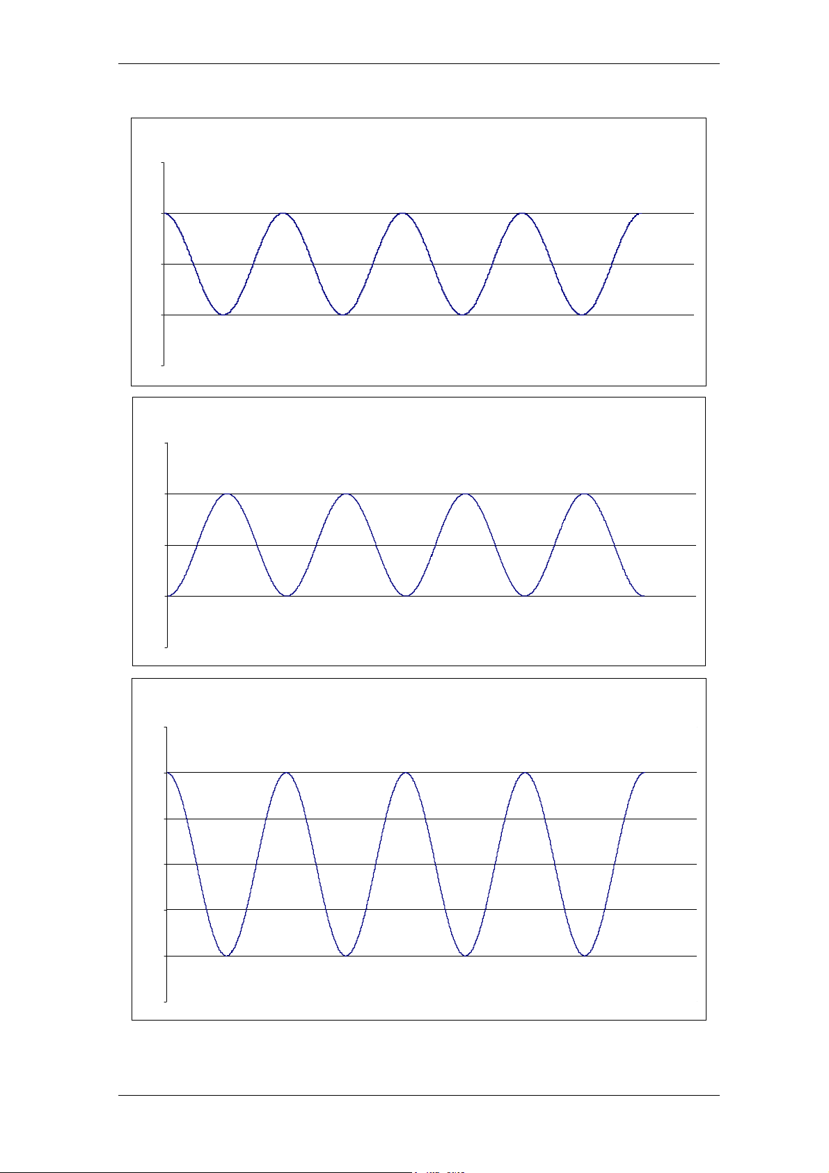
HSD
A signal temporal performance:
3
2,75
2,5
2,25
2
3
A
A-
2,75
2,5
2,25
3,25
2,75
2,5
2
A diff= (A) - (A-)
3
2,25
2
1,75
200-it_Encoder.fm (19-01-09)
HSD S.p.A.
74
Page 75
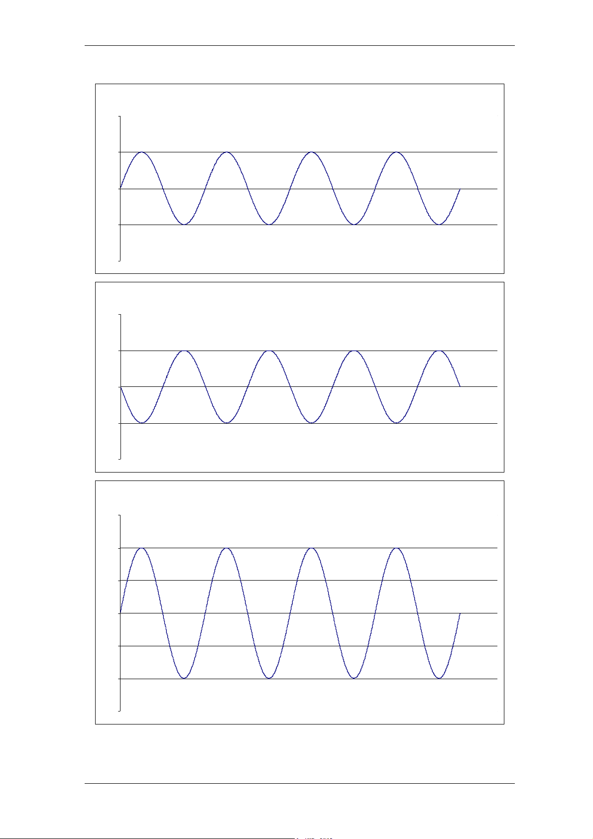
HSD
B signal temporal performance:
3
2,75
2,5
2,25
2
3
B
B-
2,75
2,5
2,25
3,25
2,75
2,5
2
B diff= (B) - (B-)
3
2,25
2
1,75
200-it_Encoder.fm (19-01-09)
HSD S.p.A.
75
Page 76
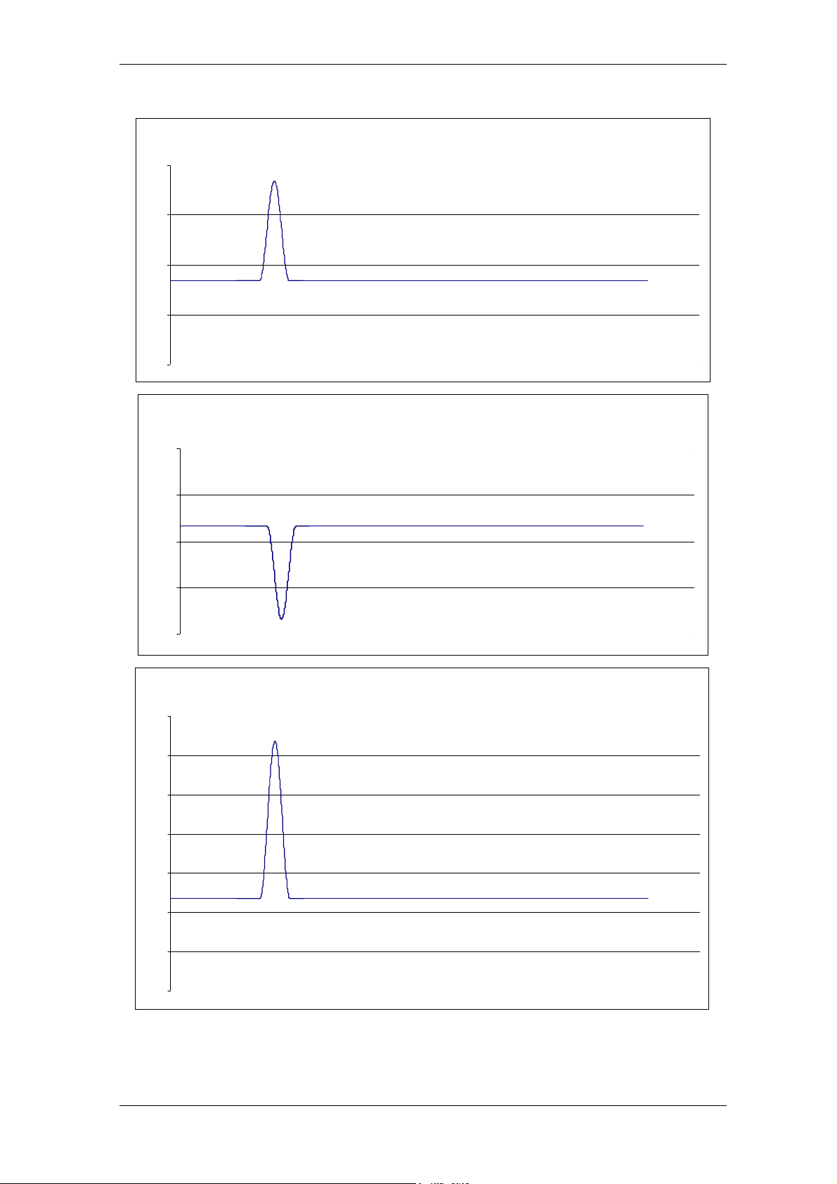
HSD
Z signal temporal performance:
3
2,75
2,5
2,25
2
3
Z+
Z-
2,75
2,25
3,5
3,25
2,75
2,5
2,5
2
Z dif f= (Z) - (Z-)
3
2,25
2
1,75
200-it_Encoder.fm (19-01-09)
HSD S.p.A.
76
Page 77
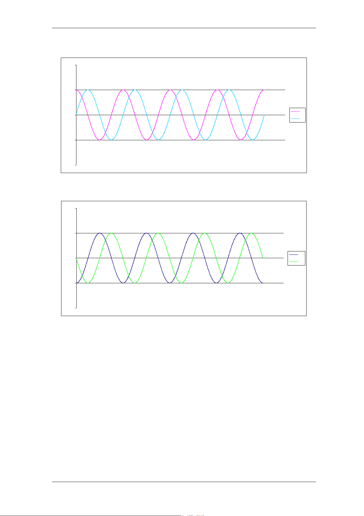
HSD
A and B signal phase difference
3
2,75
2,5
2,25
2
A and B negated signal phase difference
3
2,75
2,5
2,25
A
B
A-
B-
2
200-it_Encoder.fm (19-01-09)
HSD S.p.A.
77
Page 78
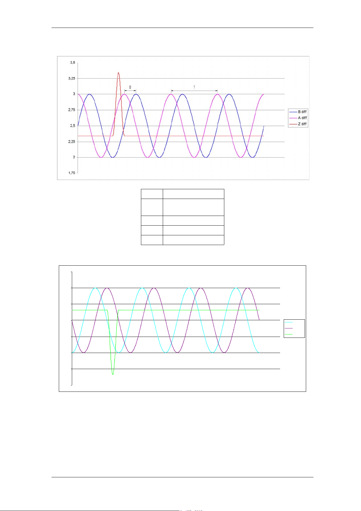
HSD
Differential signal temporal performance:
TPeriod
D Phase Difference
A diff. (A) - (A-)
B diff. (B) - (B-)
Z diff. (Z) - (Z-)
(D=T/4)
Differential negated signal temporal performance:
3,25
3
2,75
2,5
2,25
2
1,75
1,5
A diff-
B diff-
Z diff-
200-it_Encoder.fm (19-01-09)
HSD S.p.A.
78
Page 79
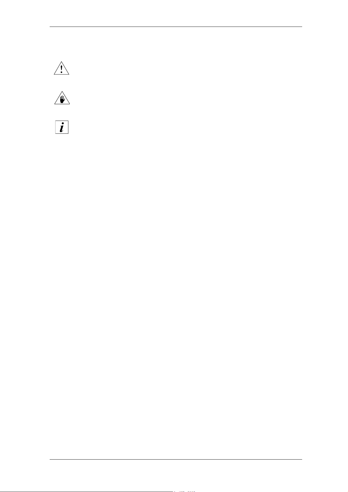
HSD
7 Scheduled maintenance
7 Scheduled maintenance
To safely operate an electrospindle installed on the machine, refer to the
specific manual of the machine.
The punctual respect of the scheduled maintenance is essential in order to
maintain the conditions of use and working planned by HSD S.p.A. when the
product was put onto the market.
The frequency has been calculated on the basis of a working week of 5 days,
each of 8 working hours, under normal environmental working conditions.
Read this section carefully before carrying out any maintenance operation on the electrospindle.
The safety regulations during the maintenance of the electrospindle must take into account that:
maintenance and/or lubrication operations must only be carried out by trained and qualified
personnel, duly authorised by the technical management of the plant, in accordance with the
safety directives and standards in force, using tools, instruments and products suitable for this
work;
during maintenance works, it is obligatory to wear suitable clothing, such as close-fitting
overalls, safety shoes, strictly avoiding wide garments or items with protruding parts;
during maintenance works, we recommend that the machine be cordoned off and the signs
indicating “MACHINE MAINTENANCE” posted.
During any maintenance operations, the electrospindle must be:
disconnected and isolated from the electric power supply;
the tool must be strictly at a standstill (not rotating).
The maintenance manager must appoint a team of persons in order to guarantee proper coordination among the team members and the maximum safety of the persons exposed to danger.
All persons involved in the maintenance operations must be in full visual contact for signalling
possible dangers.
210-it_Manut.fm (19-01-09)
HSD S.p.A.
79
Page 80
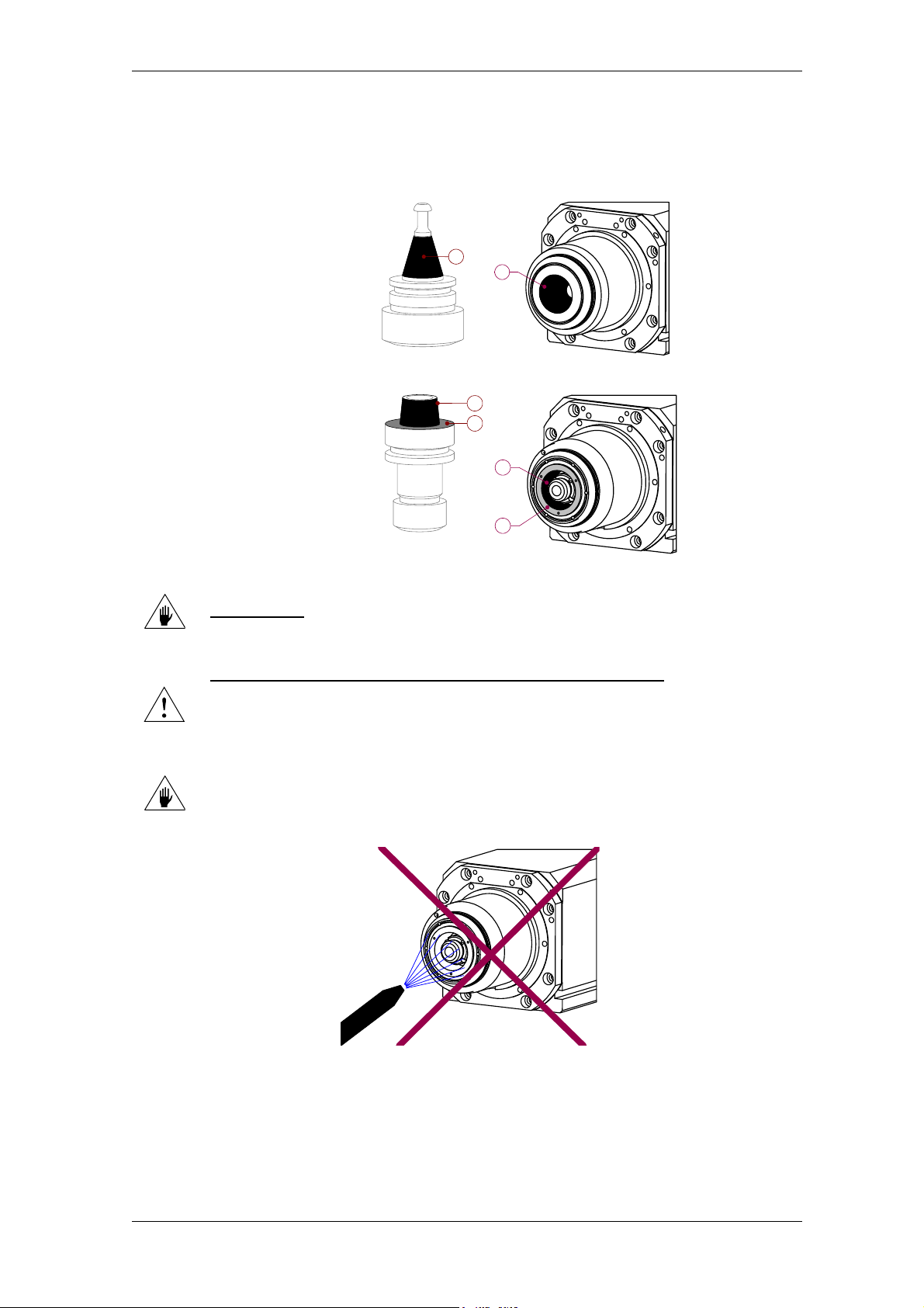
HSD
7 Scheduled maintenance
7.1 Daily maintenance
7.1.1 Checking and cleaning the tool holder seat and the tool holder cone
The contact surfaces
between the tool holder and
the tool holder seat must be
kept clean in order to
guarantee safe hooking.
At the start of the work day,
check that the surfaces
shown in figures 8 and 11 are
thoroughly clean, with no
traces of dust, grease,
cooling liquid, oil, metal
particles or machining
residues, nor signs of
oxidisation or scale;
if necessary, wipe with a
soft, clean cloth.
Figure 8 :
ISO tool holder
1
Figure 10 :
HSK tool holder
Figure 9 :
ISO tool holder seat
1
Figure 11 :
HSK tool holder seat
1
2
1
(1) Conical
surfaces
(in black)
(2) Stop
surfaces
(in grey,
only HSK)
2
For cleaning the surfaces indicated, use soft, clean cloths;
NEVER USE
cloth, acids or other aggressive elements.
abrasive instruments such as wire wool, metal scrapers, emery
At the end of the working day, clean the surfaces shown in figures 8 to 11
with a soft, clean cloth; inadequate cleaning may result in serious
consequences for the operator's safety, for the wear of the electrospindle and
tool holder, for the precision and efficiency of the machining operation.
Do not direct jets of compressed air inside the tool holder seat if the tool holder
cone is missing, or if the tool holder cone fitted has through bores (Figure 12).
Figure 12 :
NO!
210-it_Manut.fm (19-01-09)
HSD S.p.A.
80
Page 81

HSD
7 Scheduled maintenance
7.1.2 Protection of the tool holder seat
The tool holder seat must always be protected against the impurities that may come in and could
damage, oxidise or in any other way harm the contact surfaces: never leave the electrospindle
without a tool holder cone inserted.
The cone used for protection must not have through bores.
To avoid sticking, remove the tool-holder installed on the electrospindle and
replace it with a protective closing device, both after heavy machining operations
and at the end of the working day.
The protective closing device must be another clean tool-holder, at room
temperature, or one of the protective closings appropriately created by HSD and
illustrated in figures 13 to 15.
The tool holder to be removed may be hot! Use gloves!
Figure 13
Rubber cover
code H1401H0010
φ100 mm
Figure 14
ISO30 protective cone
code H1707H0030
Figure 15 HSK F63 protective
cone,
coded H1707H0031
7.2 Biweekly Maintenance
7.2.1 Clean the tool holder cone with ethyl alcohol
For all the versions:
• carefully clean the contact surfaces of the tool holders (shown in figure 8 and10) with a soft,
clean cloth dipped in ethyl alcohol;
Only for HSK versions:
• after cleaning with ethyl alcohol, spray the tapered surfaces with KLÜBER LUSIN
PROTECT G 31, and distribute the product uniformly using a clean, dry cloth;
• allow the product to dry before using the tool holder again.
210-it_Manut.fm (19-01-09)
HSD S.p.A.
81
Page 82
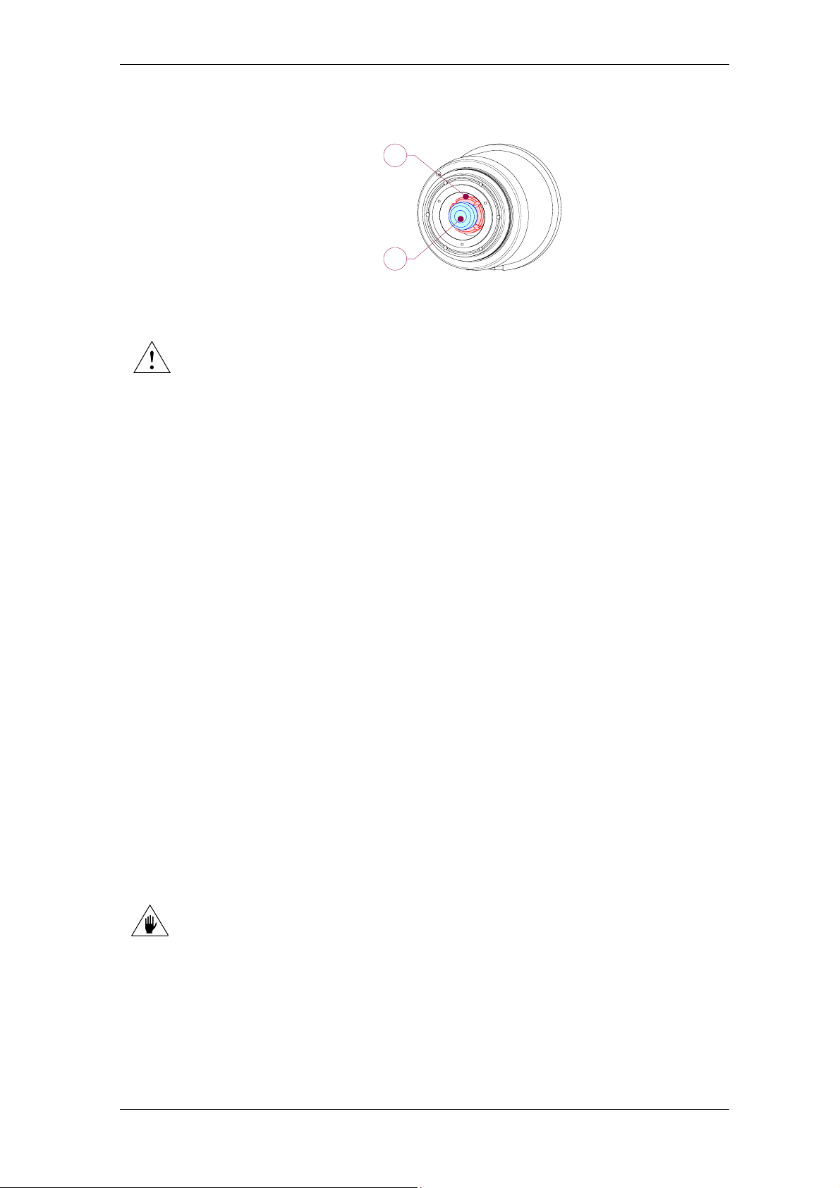
HSD
7 Scheduled maintenance
7.3 Monthly maintenance
7.3.1 Lubrication of the HSK collet
1
In order to maintain the proper
efficiency of the HSK collet over a
long period of time, it must be
lubricated every month with grease:
METAFLUX-Fett-Paste No. 70-8508
or alternatively
METAFLUX-Moly-Spray No. 70.82
USE ONLY THE GREASES INDICATED ABOVE.
Other products are not compatible with those used by HSD S.p.A. for the initial
lubrication.
Greases that are incompatible, mixed or used successively on the same collet
form substances harmful to the functioning of the collet, with serious
consequences for safety.
Proceed as follows:
spread the grease in the gap between the segments of the collet and the ejector (Figure 16),
using a clean, thin, plastic tool;
2
Figure 16
(1) Segment
s
(2) Ejector
carry out roughly ten tool changes to distribute the grease uniformly;
remove the tool holder from the spindle shaft and remove any visible remains of grease with a
clean cloth.
Excessive grease is harmful as it can collect chips or other machining residues, soiling the
collet, the tapered surfaces and the stop surfaces. These areas must be kept as clean as
possible in order to guarantee the safety of the operator, the precision of the machining
operation, and to reduce wear on the spindle and tool holder cone.
7.3.2 Check of functionality collet HSK
Frequency :6 months or 200000 tool changes
Control the expulsion limit (see limit “ B1” in table 1, pag 100)
Through a blocked tool tighten the dowel in the expeller
Check the tightening strength (using Power Check).
If the tightening force is inferior of 70 % of the nominal value, it is necessary to effect the
following operations:
• grease again , and check again the tightening force
• change the collet and check again
• change completey the thightening device
7.4 Bearings
Do not carry out any work on the bearings as these are lubricated for life with a
special grease for high speed and REQUIRE NO FURTHER LUBRICATION.
210-it_Manut.fm (19-01-09)
HSD S.p.A.
82
Page 83
HSD
8 Replacement of components
To safely operate an electrospindle installed on the machine, refer to the
specific manual of the machine.
Inside the electrospindle, there is a pre-loaded spring with a force of hundreds
of kilograms. This spring is attached to a tie-rod that may be thrown out
violently if the electrospindle is dismantled by personnel who have not been
sufficiently trained.
Carry out only the operations described in this manual, paying close attention
to the instructions given; for further information, contact HSD S.p.A. Customer
Service.
Observe the safety precautions for maintenance given on page 79.
Only the adjustment and replacement operations with original HSD S.p.A. spare
parts described in this section of the manual are permitted.
Any other type of operation is not permitted and will invalidate the product
warranty.
8 Replacement of components
220-it_Intro-Sost.fm (19-01-09)
HSD S.p.A.
83
Page 84
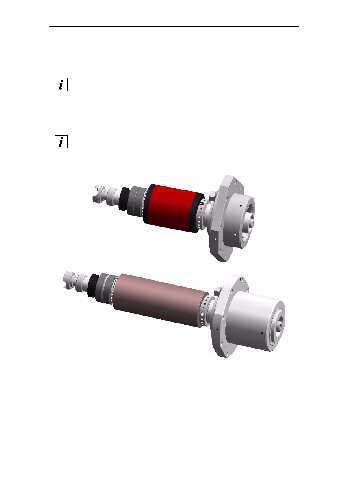
HSD
8.1 Replacement of the Shaft Kit
SPARE SHAFT KIT
Spare shaft kits are available, to install in case of bearing wear. The shaft kit has
a shaft, bearings already run in, rotor, tie-rod and coupling system.
To obtain a shaft kit suitable for your own model, inform the HSD commercial
office about the spindle serial number
The serial number is usually stamped on the front flange or the framework front
part (see section 3.1 “Main parts”)
In model ES789 with distributor for tool internal cooling, the shaft kit cannot be
replaced.Contact HSD Customer Service
Follow the instructions indicated below to replace the shaft kit.
230-it_S-KS.fm (19-01-09)
HSD S.p.A.
84
Page 85

HSD
Op. Description Image
1
If the electrospindle is provided
with encoder, remove the small
cover indicated in figure. Check
that the OR2081 is not worn or
missing.
2
Remove the 4 fixing screws of the
electrospindle casing.
3
The casing is fixed to the
electrospindle framework through
a light silicone layer: simply apply a
light force to remove the casing.
230-it_S-KS.fm (19-01-09)
HSD S.p.A.
85
Page 86
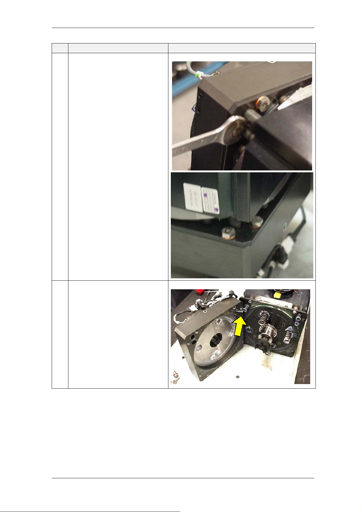
HSD
Op. Description Image
4
Remove the 8 hexagonal head
screws (2 for each angle) of the
cylinder unit.
5
Open the release cylinder unit,
paying attention to the cable
indicated in figure.
Remove the 4 springs.
230-it_S-KS.fm (19-01-09)
HSD S.p.A.
86
Page 87

HSD
Op. Description Image
6
Check that the six OR2025
indicated in figure are not
damaged or missing.
7
Check that the cone release
cylinder (upper figure) and the
piston tie-rod (lower figure) are not
worn or damaged: in this case,
only the shaft kit must be replaced,
but the electrospindle should be
sent to HSD customer service.
230-it_S-KS.fm (19-01-09)
HSD S.p.A.
87
Page 88
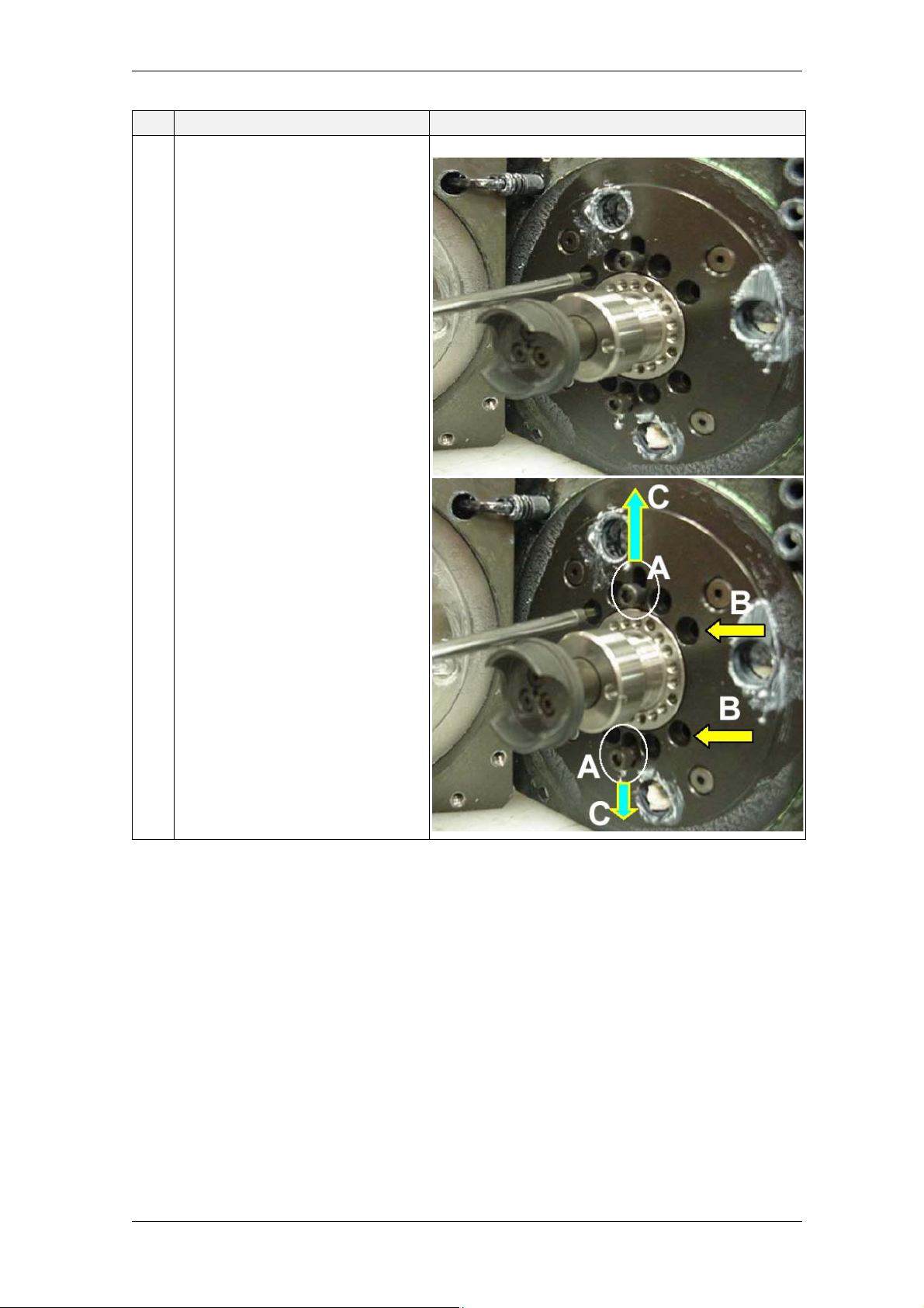
HSD
Op. Description Image
8
Screw two 5x16 screws in two oval
bores (“A”) near the piston tie-rod,
but do not fully tighten them.
Remove the eight 5x10 screws
(“B”) around the tie-rod.
Radially move both screws in the
oval bores (direction “C”) outwards
and tighten them so as to block
them in that position.
230-it_S-KS.fm (19-01-09)
HSD S.p.A.
88
Page 89
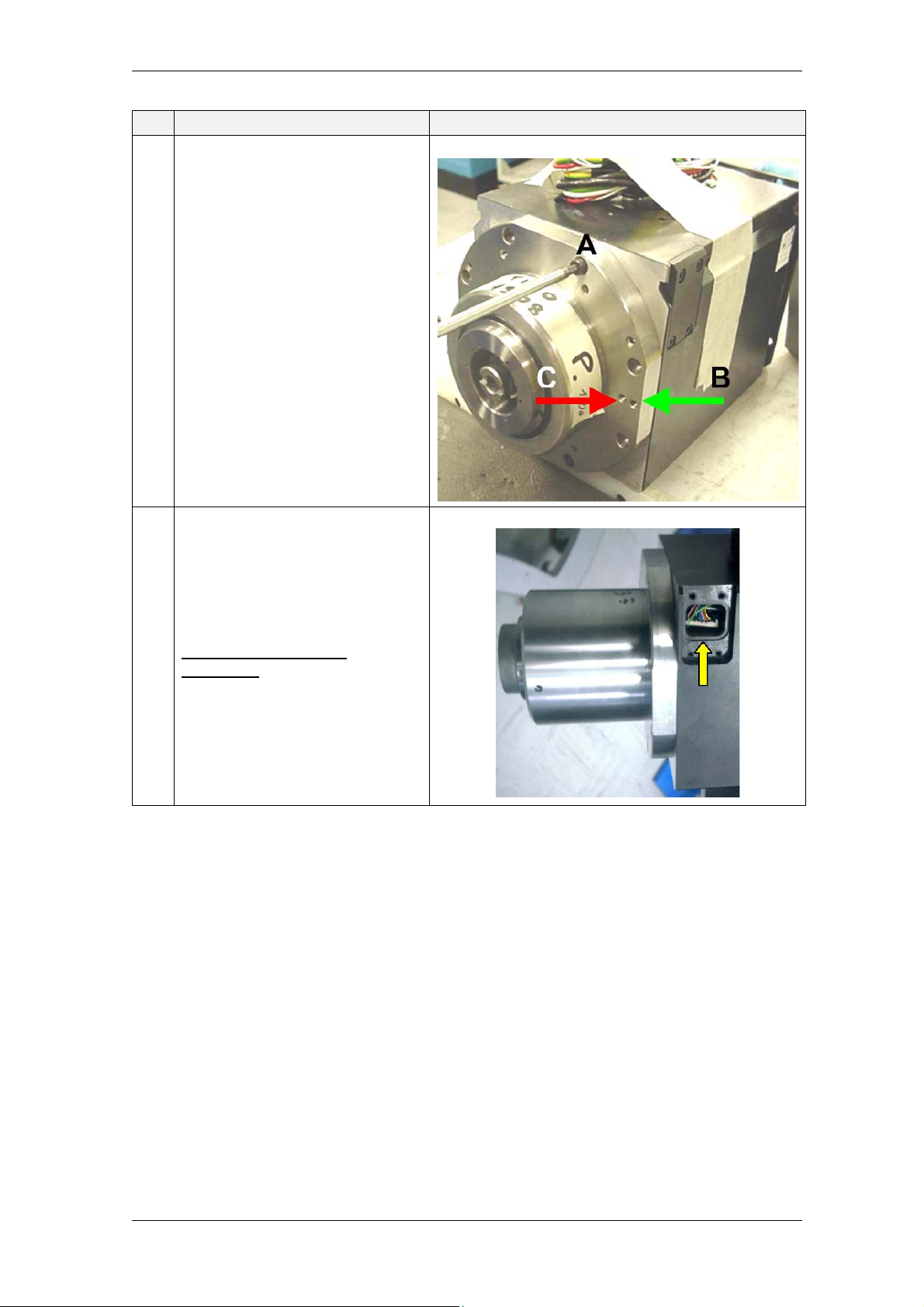
HSD
Op. Description Image
9
From the front part of the
electrospindle (“nose”), remove the
eight 5x20 screws that fix the shaft
[figure alongside, (C)].
To extract the shaft kit, use two
headless, flat end screws (UNI
5923), M5x20 or longer.
Insert the screws in the bores
indicated with (B) (the outer bores,
one on each side).
DO NOT use the bores marked
with (C) (those inside).
10
Carefully take out the shaft kit by
some centimetres.
FOR VERSIONS WITH
ENCODER: Check, from the
window, that the Encoder wiring
does not get entangled.
230-it_S-KS.fm (19-01-09)
HSD S.p.A.
89
Page 90
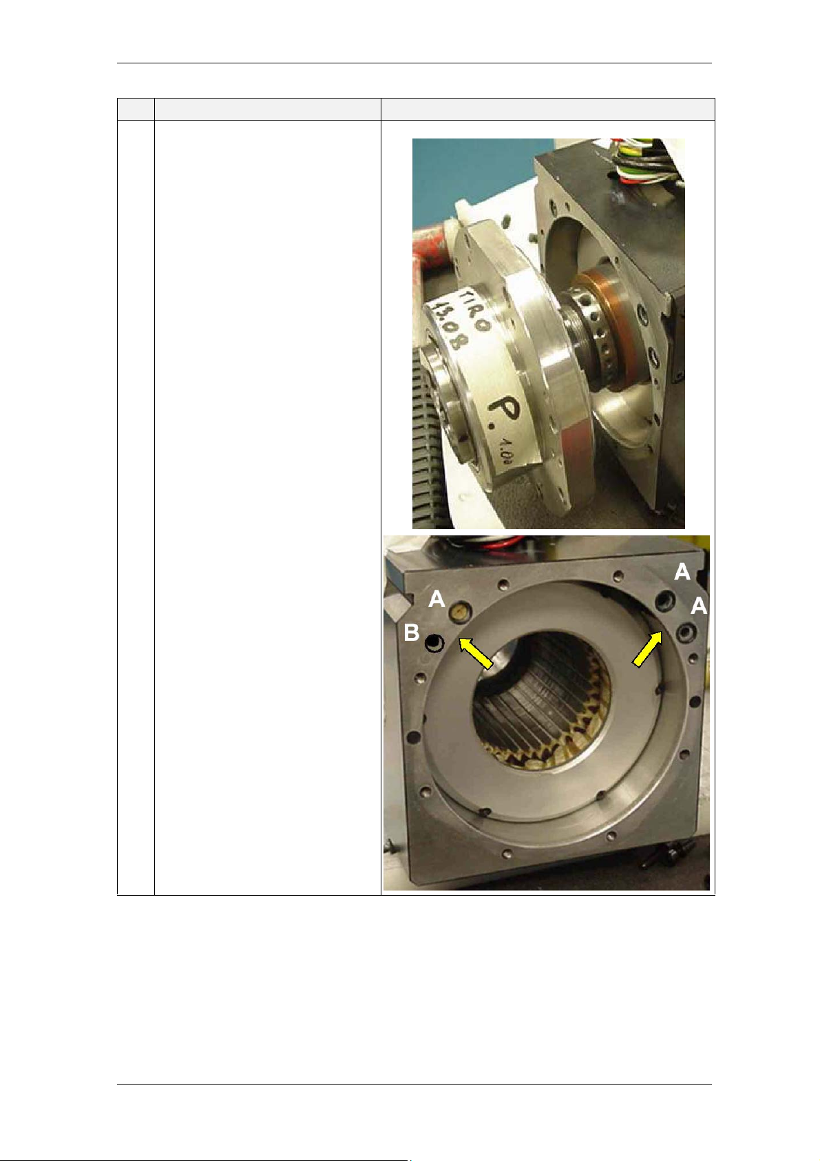
HSD
Op. Description Image
11
Check that the 3 ORM 0080-15
indicated in figure “A” and the
ORM 0050-15 indicated in “B” are
not damaged or missing.
NOTE: in some models, bore “B” is
not present.
230-it_S-KS.fm (19-01-09)
HSD S.p.A.
90
Page 91
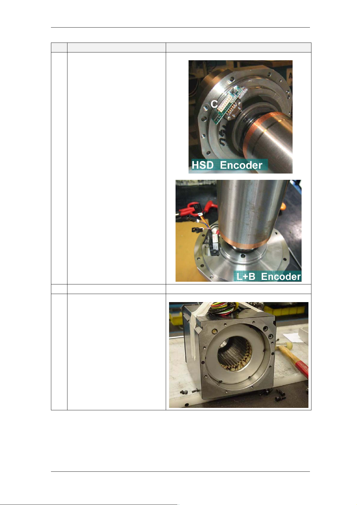
HSD
Op. Description Image
12
VERSIONS WITH HSD
ENCODER:
Disconnect the connector “C”.
VERSIONS WITH L+B
ENCODER:
Disconnect the three connectors
indicated in figure.
13 Remove the shaft kit.
14
Clean resting surfaces and grease
bearing seats.
230-it_S-KS.fm (19-01-09)
HSD S.p.A.
91
Page 92
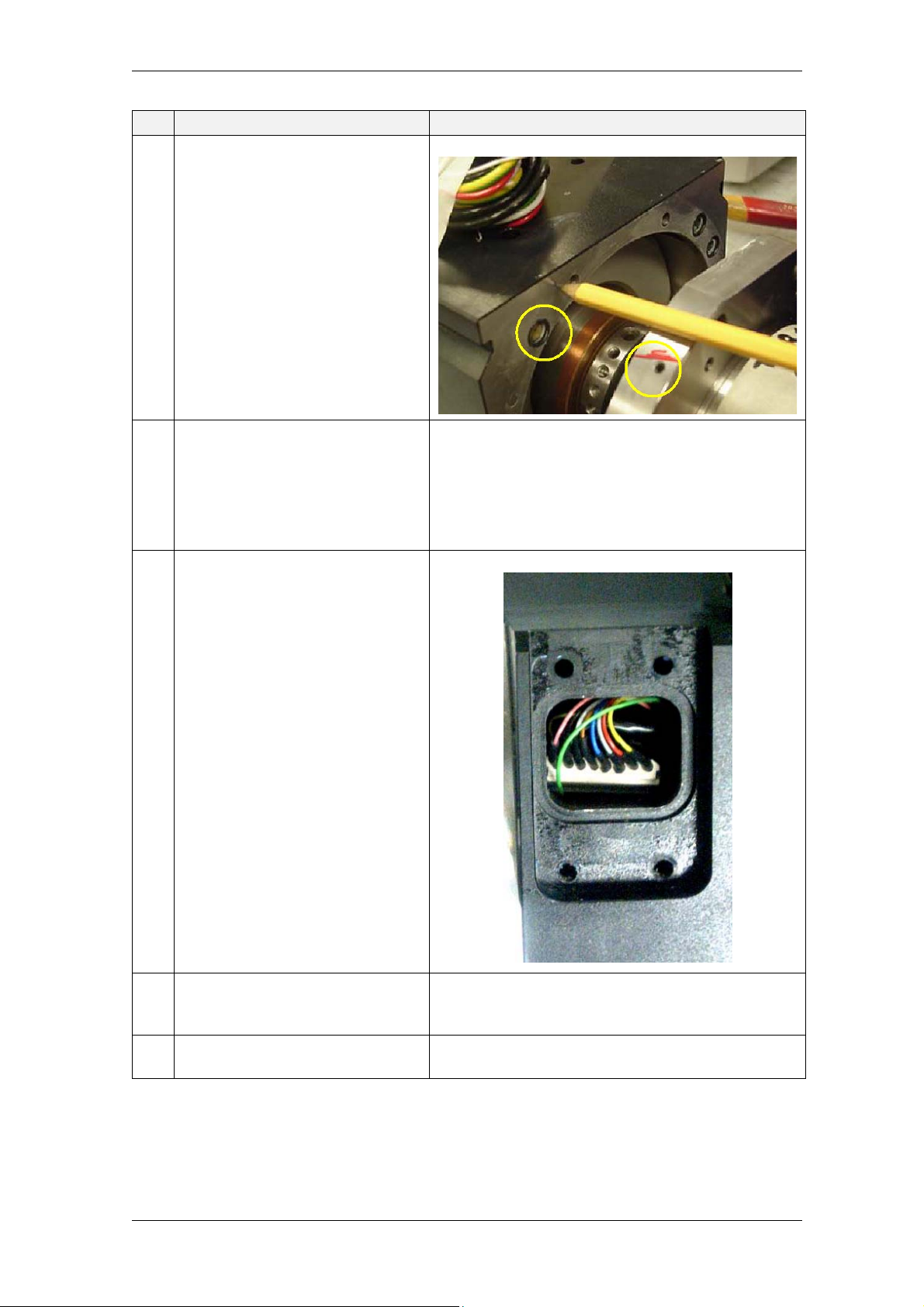
HSD
Op. Description Image
15
Insert the new shaft kit partially.
Be careful when aligning the bore
for pressurisation air passage of
the shaft with that on the flange.
16 VERSIONS WITH HSD
ENCODER:
Connect the connector “C”.
VERSIONS WITH L+B
ENCODER:
Check the three connectors.
17
FOR ALL VERSIONS WITH
ENCODER:
Insert the shaft kit completely into
the electrospindle by slightly
pulling the encoder wiring through
the window; position the wiring and
the encoder connector so as not to
cause interference with rotating
parts.
18 Insert the shaft completely into the
electrospindle being careful with
the OR shown in point “11”.
19 Refit removed parts in points 9, 8,
4, 3 and 1.
230-it_S-KS.fm (19-01-09)
HSD S.p.A.
92
Page 93
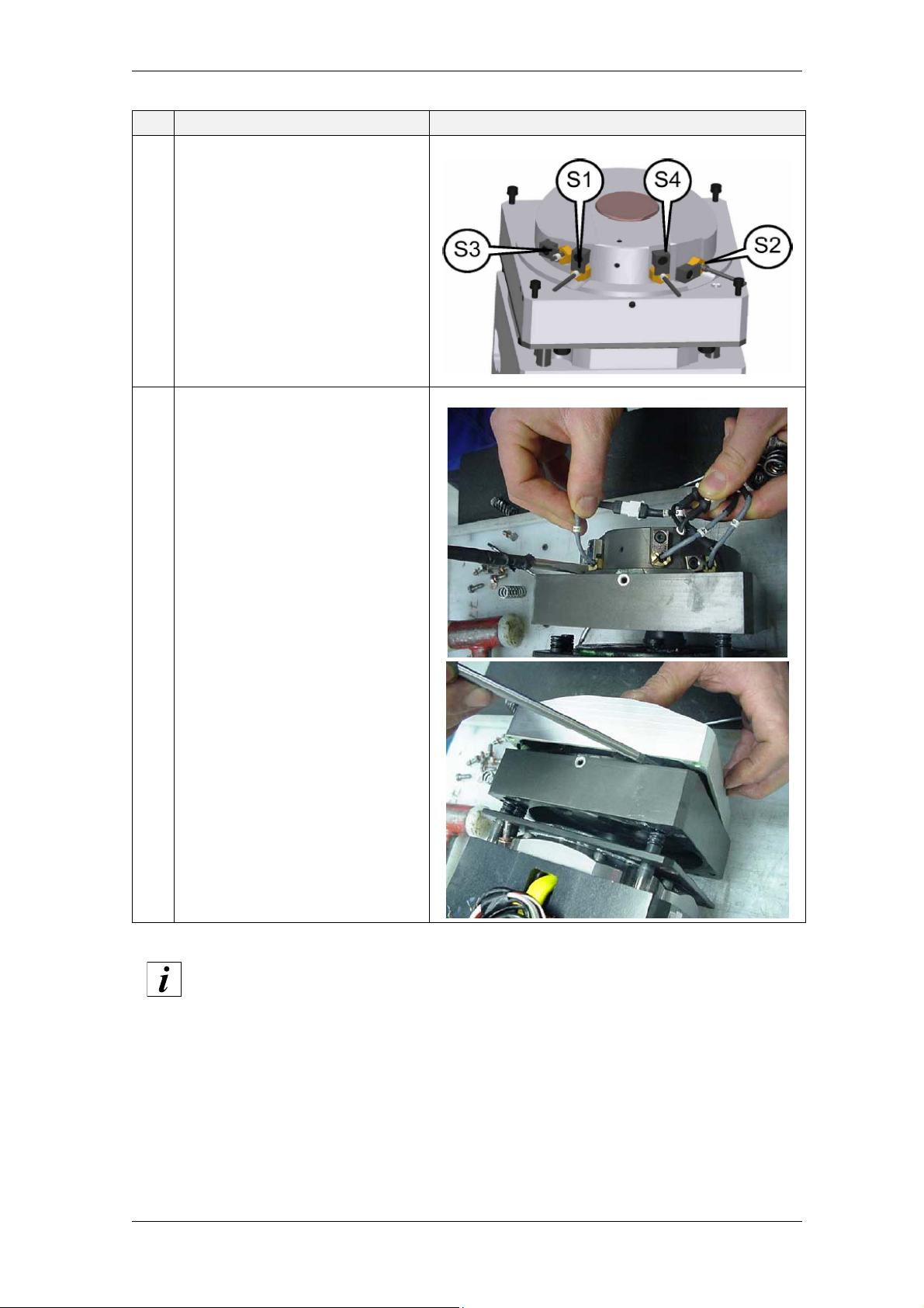
HSD
Op. Description Image
20
Carry out sensor calibration as
described in section 8.3
“Replacement and adjustment of
the sensor group”.
21
Refit the upper cover casing of the
electrospindle being careful not to
damage sensors.
Use Loctite 510 or an equivalent
product on the casing edge.
To ensure maximum accuracy in machining operations, it is recommended to
set to zero the axis affected by the modification in the machine (axis parallel to
spindle shaft)
Summary of OR used in the shaft kit:
• OR 2081
• OR 2025
• ORM 0080-15
• ORM 0050-15
230-it_S-KS.fm (19-01-09)
HSD S.p.A.
93
Page 94

HSD
8.2 Replacement of the encoder reader
In case the encoder reader must be replaced, follow the shaft kit removal procedure until point “12”
and proceed as follows:
Models of HSD Square Wave encoder:
loosen the two fixing screws of the optical reader,
delicately lift the reader from its seat,
carefully slide the reader from the encoder disk being careful not to scratch it,
more delicately, position the new reader and slot it into its seat,
lock the two fixing screws,
check that, by rotating the shaft, the encoder disk is at the same distance from both ends of
the optical reader fork,
follow backwards the shaft kit assembly procedure.
Models with Lenord-Bauer sinusoidal encoder
unlock the two fixing screws,
unlock the screw fixing the reader earth cable to the flange,
remove the faulty reader,
place the new reader in its seat keeping it at distance from the toothed wheel,
lock the two screws without tightening them fully,
interpose the thickness spacer between the toothed wheel and the new reader,
Place the thickness spacer between the toothed wheel and the encoder reader
BEFORE carrying out other operations.
Otherwise, the magnetic component of the reader can be attracted and collide
with the toothed wheel, with possible damages to the reader.
push the reader towards the toothed wheel, moving everything “together”,
tighten definitively the two fixing screws of the reader,
slide off the thickness spacer previously placed,
visually check that, when turning the shaft, the toothed wheel does not touch the reader,
lock again the screw fixing the reader earth cable to the flange,
follow backwards the shaft kit assembly procedure.
230-it_S-KS.fm (19-01-09)
HSD S.p.A.
94
Page 95
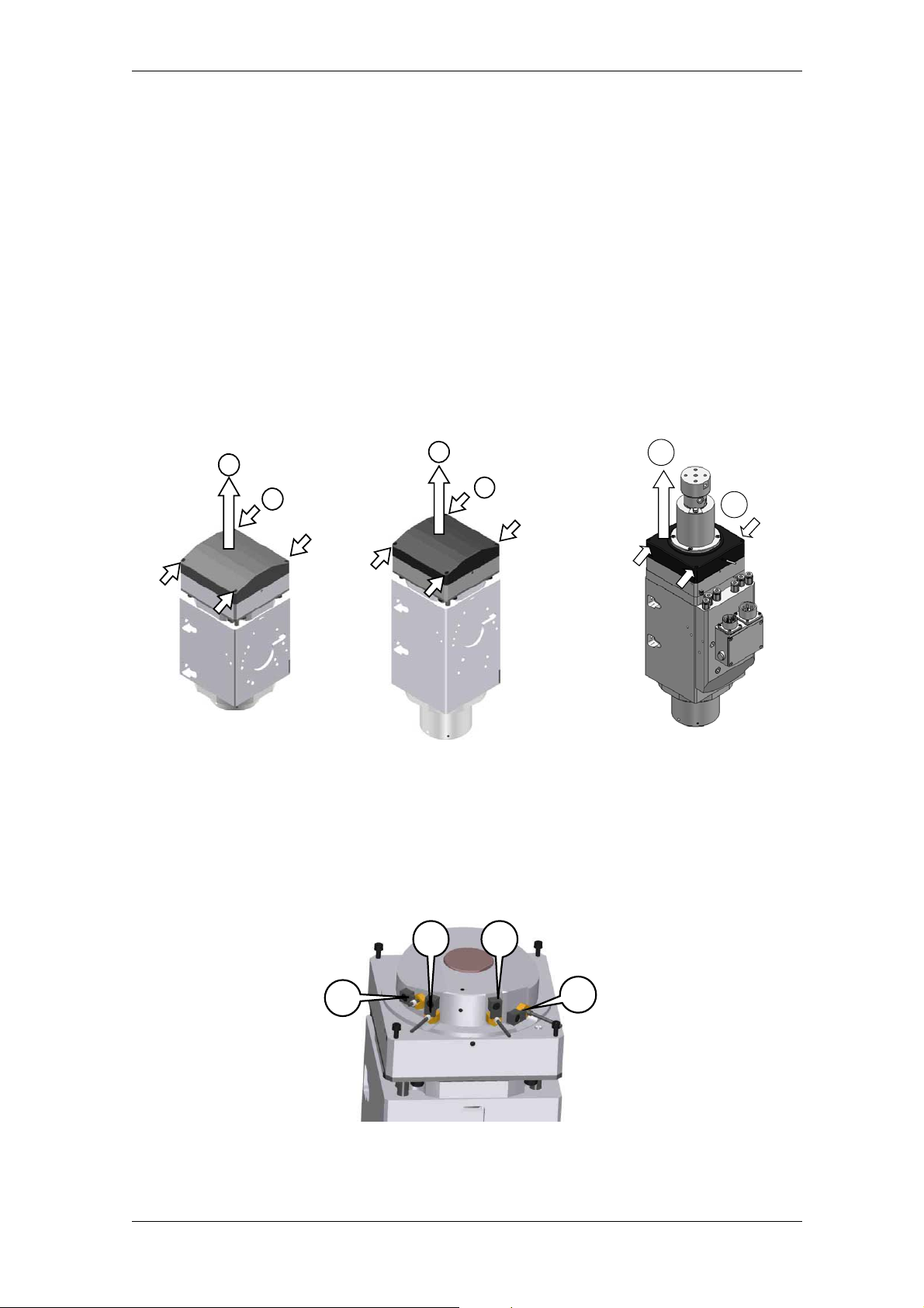
HSD
8.3 Replacement and adjustment of the sensor group
8.3.1 Access to the sensors
Refer to figures 17 to 18 to access to sensor zone.
Unlock the four screws (1).
Remove the casing (2) according to the direction of the arrow in figure.
The casing is fixed to the electrospindle framework through a light silicone layer: simply apply
a light force to remove the casing.
When refitting the casing (2), pay attention not to damage sensor cables inside. Moreover,
apply Loctite 510 or an equivalent product on the casing edge.
Figure 17: ES779
2
1
Figure 18: ES789
2
1
Figure 19: ES789 with distributor
2
1
8.3.2 Identification of the sensors
Figure 20: ES779 and ES789
S1 S4
S3
250-it_S-Sens.fm (19-01-09)
HSD S.p.A.
S2
95
Page 96
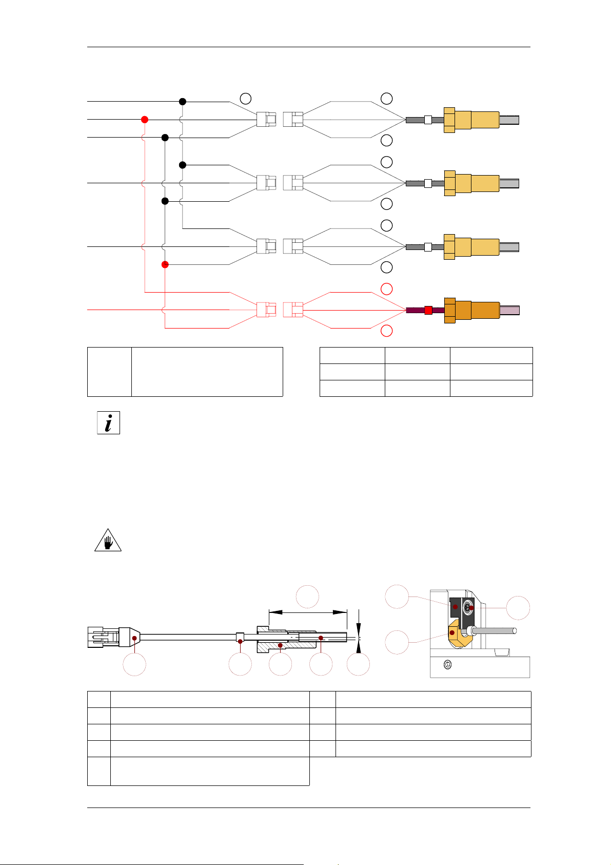
HSD
8.3.3 Sensor wiring
(X)
X
11
22
33
44
For the colours of the userside, see the table in
section 4.10.
+
Output
1
-
+
Output
2
-
+
Output
3
-
+
Output
4
-
(+) Brown + 24V DC
Output Black ON / OFF
(-) Blue 0V
S1
S2
S3
S4
The S1 sensor is present only in HSK versions.
8.3.4 Description of the sensor unit
The sensors are pre-assembled in calibrated bushes to allow simple insertion to the right depth in
the electrospindle. It is therefore important to correctly identify the sensor to be replaced: for this
reason, both the sensors installed on the electrospindle and those supplied as spare parts bear a
numbered label (see figure below
Confusion of the sensors will result in damage to the moving parts.
Figure 21: sensor unit Figure 22: sensor fixing
6
7
9
3
8
1
1 Electrical connector 6 Calibrated position
2 Numbered label 7 Bracket
3 Bush 8 Sensor unit
4 Sensor 9 Screw
Eccentricity between bush and regulation
5
sensor
3
42 5
250-it_S-Sens.fm (19-01-09)
HSD S.p.A.
96
Page 97

HSD
8.3.5 Replacement and adjustment of the sensor unit
For the replacement and adjustment of the sensors shown in this paragraph (and those
to follow), always refer to figures 21 and 22 of the previous paragraph.
8. remove screw “9” that blocks the bracket “7” of the sensor unit “8” to be replaced;
9. Unthread the faulty sensor unit from its seat, and disconnect its electrical connector“1”.
10. connect the electrical connector of the new sensor unit to the correspondingly numbered
connector of the spindle;
11. check the functioning of the new sensor by bringing it into contact with a metallic mass;
12. Insert the new sensor unit in the empty seat;
13. reposition the bracket “7” and lock the screw “9” again without tighten it completely, so that the
sensor unit can rotate;
14. rotate the sensor unit a few degrees at a time, until you obtain the outputs requested in the
paragraphs immediately below;
15. tighten the screw “9” by blocking the sensor unit with an open-end spanner so as to maintain
the calibration carried out.
250-it_S-Sens.fm (19-01-09)
HSD S.p.A.
97
Page 98

HSD
8.3.6 Sensor S1 adjustment (for all models)
For HSK models, a kit of gauges and thickness spacers is available for
adjustment of S1 and S4 sensors; the kit is described in paragraphs 8.3.11 to
8.3.13.
The use of the kit allows a quicker and more precise adjustment: HSD S.p.A.
strongly recommends the use of the kit, given the importance (for safety
purposes) of a correct sensor adjustment.
After replacing the sensor unit as described in section 8.3.5, adjust it as follows:
1. do not tighten the sensor completely until an accurate adjustment has been performed;
2. attach the tool holder cone and ensure that the output of S1 is “ON”; if the output is “OFF”,
rotate the sensor unit until it becomes “ON”;
3. the sensor “4” is eccentric in relation to the bush “3” that contains it: rotate the bush slowly in
the direction that takes the sensor away from the tool holder;
stop immediately when the output of the sensor becomes ”OFF”;
4. carefully rotate the bush back by about 15° - 20°, so that the output of the sensor returns to
“ON”;
5. rotate the shaft manually, and check that the signal remains “ON” for the whole rotation;
6. tighten fixing screw “9”;
7. release the tool holder by powering the piston at the pressure indicated in the section 4.6
“Pneumatic connections”, and check that in this condition (collet open) the output of S1 is
“OFF”;
8. release the pressure at the piston and allow the collet to close without tool holder: in this
condition, the output of S1 must be “OFF” for the whole rotation of the shaft;
9. if points (7) and (8) are not satisfied repeat the procedure from the start, making an even
slighter rotation movement at point (4);
10. if points (7) and (8) are satisfied, make a cycle of 10 tool changes;
11. at the end of the cycle, check that the conditions in the following table are satisfied:
CONDITION S1 OUTPUT
tool holder locked
missing tool holder
with closed collet
collet open
(tool holder ejected)
* for the whole rotation of the shaft
ON *
OFF *
OFF
12. if the conditions of the table are not satisfied, repeat the procedure from the beginning;
13. if the conditions of the table are satisfied, perform a cycle of 100 tool changes with the
machine, using the maximum possible number of different tool holders.
14. At the end of the cycle, check that the conditions in the table under point (11) are satisfied: if
this is the case, the regulation procedure for S1 is complete; if this is not the case, repeat
the procedure from the beginning.
250-it_S-Sens.fm (19-01-09)
HSD S.p.A.
98
Page 99

HSD
8.3.7 S2 sensor adjustment for ISO models
After replacing the sensor as described in section 8.3.5, calibrate it as follows:
1. correctly attach a tool holder before beginning the adjustment of the sensor;
2. check that, in this state, the output of S2 is “OFF”; if the output is “ON”, rotate the sensor unit
until it becomes “OFF”;
3. feed the cylinder by means of a one-way pressure regulator initially set at 0 bar (0 PSI);
4. increase the feed pressure by steps of 0.1 bar (1.5 PSI) so as to move the piston slowly
forward and, at the same time, check that the output of S2 is “OFF”;
5. as long as the tool holder is firmly blocked, the output of S2 must be “OFF”;
if the output changes during the movement of the piston, slightly rotate the sensor unit until the
output returns to “OFF”;
6. when the tool holder begins to slacken (but is not yet free to fall), the output of S2 must still be
“OFF” (if necessary, rotate the sensor unit);
7. when you reach the feed pressure at which the tool holder is finally free to fall, increase the
pressure by another 0.2 bar (3 PSI) and block the pressure regulator;
8. rotate the sensor unit so that, in this state, the output of S2 becomes “ON”;
9. perform a cycle of 10 tool changes;
10. at the end of the cycle, check that the steps from (1) to (8) are satisfied without the need to
ever rotate the sensor;
11. if the outputs requested are not satisfied, repeat the entire procedure from the start;
12. if the outputs requested are satisfied, perform a cycle of 100 tool changes with the machine,
using the maximum possible number of different tool holders;
13. at the end of the cycle, check that the steps from (1) to (8) are satisfied without the need to
ever rotate the sensor;
14. if the outputs requested are not satisfied, repeat the entire procedure from the start;
15. if the outputs requested are satisfied, the regulation procedure for S2 is complete.
250-it_S-Sens.fm (19-01-09)
HSD S.p.A.
99
Page 100
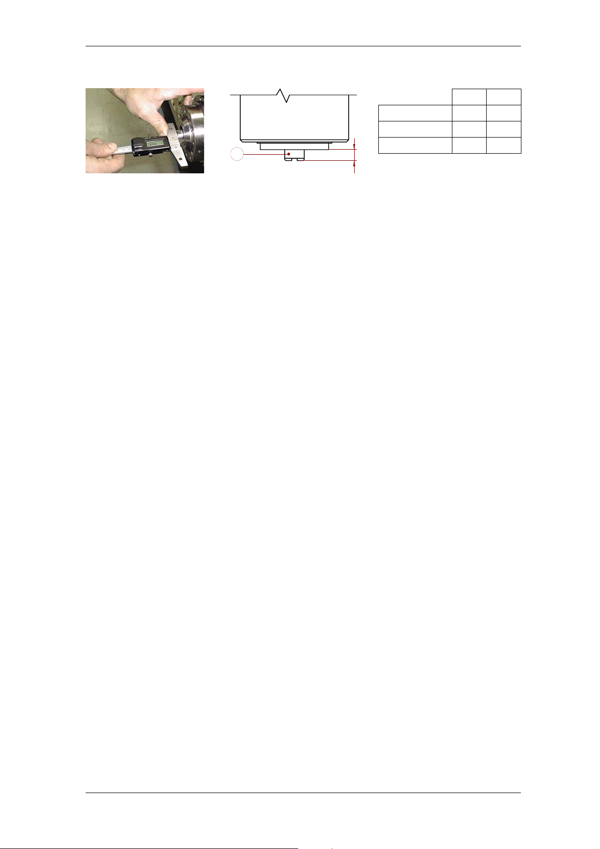
HSD
8.3.8 Sensor S2 adjustment for HSK models
A
B1 B2
HSK E25 6.5 6.35
HSK E40/F50 8.5 8.35
HSK A/E/F63 10.5 10.3
(+/- 0.1 mm)
B
Figure 23: position of the ejector Figure 24: (A) ejector
(B) reference position
After replacing the sensor as described in section 8.3.5, calibrate it as follows:
1. bring the spindle to the “collet open (tool holder ejected)” status by feeding the cylinder with
the pressure indicated in section 4.6 “Pneumatic connections”;
in these conditions, the position (B) (figure 24) takes on the maximum value;
2. as shown in figures 23 and 24, use a depth gauge to check that the position (B) of the ejector
in relation to the spindle nose takes on the value “B1” indicated in table 1;
if this is not the case, stop and contact HSD Customer Service;
3. fully discharge the pressure from the cylinder;
in these conditions, the position (B) takes on the minimum value;
4. feed the cylinder by means of a one-way pressure regulator initially set at 0 bar (0 PSI);
5. increase the pressure in steps of 0.1 bar (1.5 PSI), so as to slowly move the ejector forwards;
6. stop when position (B) reaches the value “B2”;
7. if necessary, loosen the screw “9” (Figure 22 “: sensor fixing”) of sensor S2;
8. rotate sensor S2 until you find the position supplying the signal “ON” with (B) > B2 and “OFF”
with (B) < B2;
9. finally tighten screw “9” completely;
Table 1 : values of (B)
10. perform a cycle of 10 tool changes;
11. at the end of the cycle, check that point (8) has been met without the need to rotate the
sensor;
12. if it is necessary to rotate the sensor, repeat the whole procedure from the beginning;
13. if it is not necessary to rotate the sensor, perform a cycle of 100 tool changes with the
machine, using the maximum possible number of different tool holders;
14. at the end of the cycle, check that point (8) has been met without the need to rotate the
sensor;
15. if it is necessary to rotate the sensor, repeat the whole procedure from the beginning;
16. if it is not necessary to rotate the sensor, the S2 adjustment procedure is complete.
250-it_S-Sens.fm (19-01-09)
HSD S.p.A.
100
 Loading...