

HRS IC11S Service Manual
A2
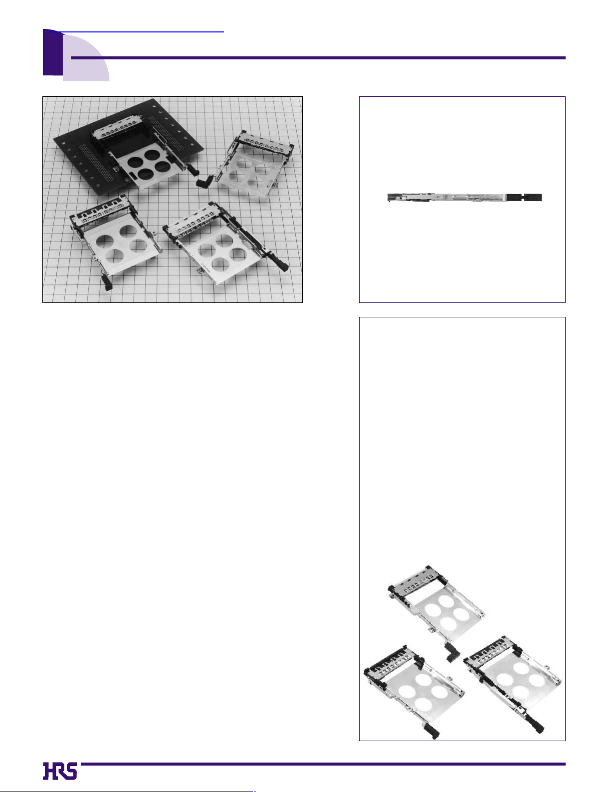
Single Slot SMT Connectors For Card-Bus Based PC Cards
IC11S Series PC Card Standard Compliant
Reduced height : 5.6mm high
Wide variety of options
(1)Board Mounting
➀Standard type
➁Reverse type
(2)Types of eject button
➀Rigid button
➁Foldering button
➂Pop-up button
(3)Position of eject buttons
➀Right
➁Left
(4)Standoffs
➀None
➁2.2mm
■Features
1. PC Card Standard compliant:
• Grounding is required to meet the high speed signal
requrements of the PC card standard. Grounding reliability is
achieved with a grounding plate and 8 grounding contacts.
• Type 1, type 2 and type 3 cards are covered.
• Terminals for ground clipping are provided.
2. Space saving
Smaller size reduces occupied area on PC boards as
compared to previous products.
3. Reduced Height:
Connector height is minimized to 5.6mm, making possible
thinner product designs.
4. Eject mechanism with high-level functionality
Hirose Electric's original ejection mechanism provides an
higher degree of card ejection over existing products. This
improves the operational qualities of card removal. (Patents
pending)
5. Wide Variety of Options Available
• Standard type mounts to the top of the PC board and reverse
type mounts on the underside of the board
• Three types of eject buttons; rigid, flexible and POP-UP.All
types can be installed on the right or left side of the ejector.
• Available with standoff to utilize space under the connector for
mounting other parts.
6. Light-weight
Weight of 12.7g for normal button type helps achieve the
reduced weight required in today’s products.
查询IC11S-68PL-1.27SF-EJL供应商
A3
■Product Specifications
■Material
SMT unit
Parts
Insulator
Ground plate
Card connected section
Eject metal fittings
Contact
Material Finish
Finish
Remarks
Remarks
PPS
Stainless steel
Phosphor bronze
Brass
Contact section: gold plating
Lead section: solder plating
----------
Contact section: gold plating
Lead section: solder plating
Black UL94V-0
----------
----------
----------
Item
Guide plate
Push rod
Eject Button
Rigid button type
resin section
resin section
spring
spring pin
resin section
frame metal
spring
pin
Foldering
button type
POP-UP type
Nut
Stainless steel
Stainless steel
PBT
PBT
Stainless steel
Stainless steel
PBT
Stainless steel
Steel
Brass
Steel
----------
---------Color : Black
Color : Black
----------
---------Color : Black
----------
----------
Nickel plating
----------
----------
---------UL94V-0
UL94V-0
----------
---------UL94V-0
----------
----------
----------
M2X0.4
Material
Item
1.
Insulation resistance
2.
Withstanding voltage
3.Contact resistance
5.
Humidity (Steady state)
4.Vibration
6.Temperature cycle
7.
Durability
(Insertion/withdrawal)
8.Resistance to
Soldering heat
Specification Conditions
1000M ohms min.
No flashover or insulation breakdown.
60m ohms max. (initial value)
Insulation resistance: 100M ohms min.
No electrical discontinuity of 100ns or more
Insulation resistance: 100M ohms min.
Variations from initial contact resistance: 20m
ohms max.
No deformation of components affecting
performance.
500V DC
500V AC
1mA
(-55ç:30min.
/
+5ç to 35ç:MAX 5min/85ç:30min/+5
-35ç:MAX 5min.) 5 cycles
96 hours at temperature of 40ç and humidity of 90% to 95%
10000 cycles at 400 to 600 cycles per hour
Reflow: At the recommended temperature profile
Manual soldering: 300ç for 3 seconds
Frequency: 10 to 2000 Hz, full amplitude of 1.52 mm or
acceleration of 147 m/s
2
(peak), 4 hours in each of the 3 directions.
Note 1: Includes temperature rise caused by current flow.
Note 2: The term "storage" refers to products stored for long period of time prior to mounting and use. Operating Temperature
Range and Humidity range covers non- conducting condition of installed connectors in storage, shipment or during
transportation.
Guide unit
Ratings
Current rating 0.5A
Operating temperature
-55ç to +85ç(Note.1)
Storage temperature
-
40ç to +70ç(Note.2)
Voltage rating 125V AC
Operating humidity
Relativehumidity 95% max.
(With no dew-fall)
Storage humidity
40% to 70%(Note.2)
A4
(Note.) IC11S Series will be used in combination of SMT unit with guide unit. When using, please select
the same type for the following items. Please note that other combinations cannot be used.
Board Mounting Type:
PL : standard type
PLR : reverse type
Number of contacts : 68
Standoff type
Blank : none
A : 2.2mm
Series name : IC11S 1.27SF : 1.27mm pitch SMT connector
With ejector
EJ : with ejector
Eject button positions
R : right
L : left
1 5
6
7
2
3
4
IC11S A - 68 PLR - 1.27SF - EJ R
1 2 3 6 74 5
■Ordering Information
SMT Unit
Guide Unit
Board Mounting Type
BD : standard type
BUR : reverse type
Standoff type
Blank: none
A : 2.2mm
Series name : IC11S
Eject button type
EJ : rigid button
FEJ : Foldering button
PEJ : POP-UP button
Eject button positions
R : right
L : left
8
11
12
9
10
IC11S A - BUR - FEJ R
8 9
1210 11
• Series name ( ⇔ )
• Standoff ( ⇔ )
• Board-installed type ( ⇔ )
• Eject button positions ( ⇔ )
1 8
2 9
4
10
7
12
A5
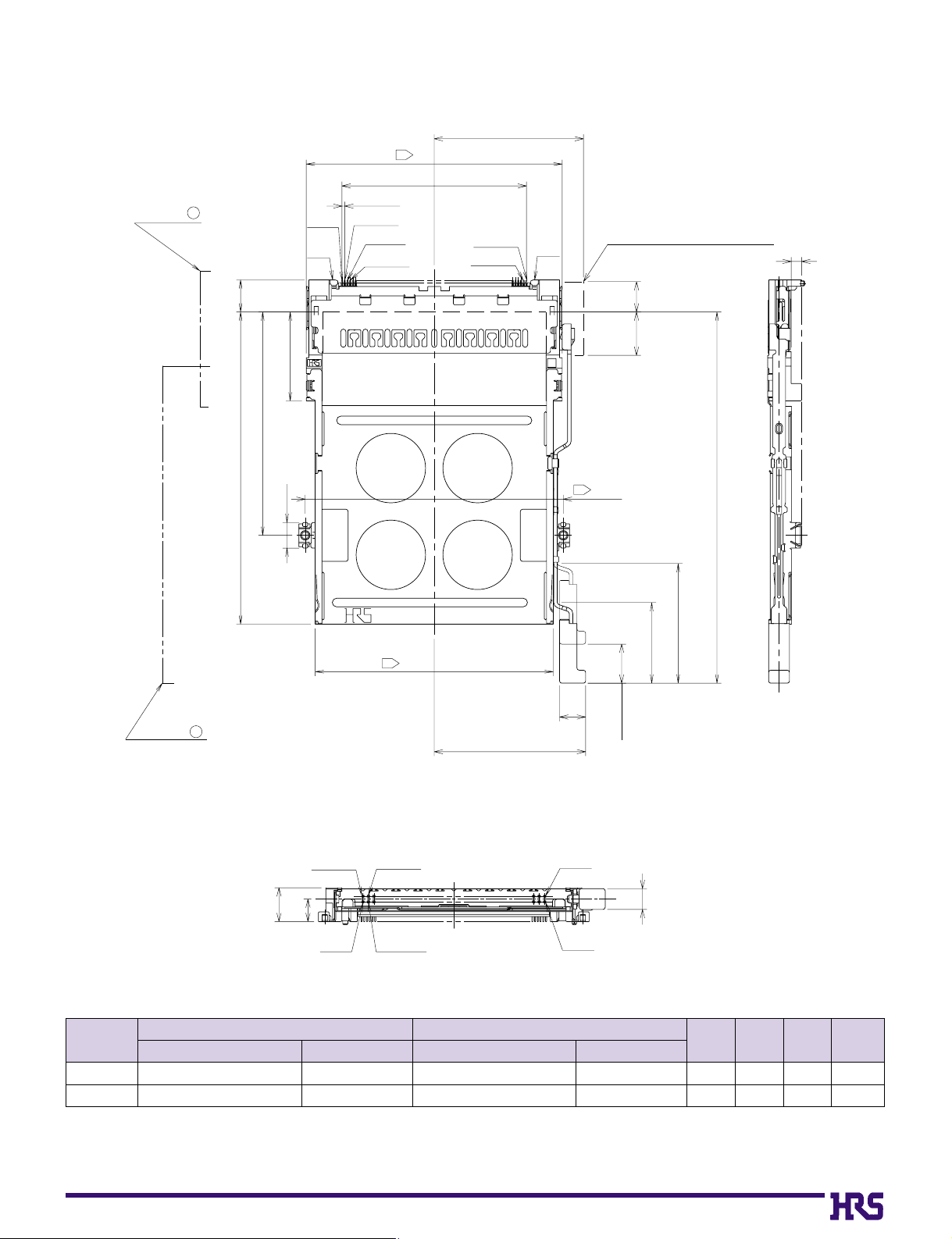
Note.1) This figure illustrates grouping of SMT unit(➀) and guide unit(➁) together.
Note.2) Dimensions for card fitting are in accordance with "PC Card Standard".
Note.3) Indicated dimensions are symmetrical to the center of the card insertion slot.
■Standard
Right rigid button type
Standoff
type
none
2.2mm
640-1007-3
640-1009-9
IC11S-68PL-1.27SF-EJR
IC11SA-68PL-1.27SF-EJR
640-1071-2
640-1073-8
IC11S-BD-EJR
IC11SA-BD-EJR
3
5.2
5.6
7.8
0.1
2.3
12.7
13.1
➀
SMT unit
CL No.Part Number
➁
Guide unit
A
(mm)B(mm)C(mm)
Weight
(g)
CL No.Part Number
SMT unit ( )
1
No.1
GND
P= 0.635
No.35
No.2
No.36
3
59
42.545
34.4 MAX
No.68
No.34
GND
eject metal fittings movable range
C
guide unit ( )
2
7.472
51.5
20.5
5.9
P U S H
7MAX
A
P U S H
3
3
54.9
6
( 34.9)
10MAX
59.5
85.6: in card insertion
(27.6)
(18.6)
stroke:9
No.34
No.68
B
No.1
A
No.35
No.2
No.36
4.8
A6
Note.1) This figure illustrates grouping of SMT unit(➀) and guide unit(➁) together.
Note.2) Dimensions for card fitting are in accordance with "PC Card Standard".
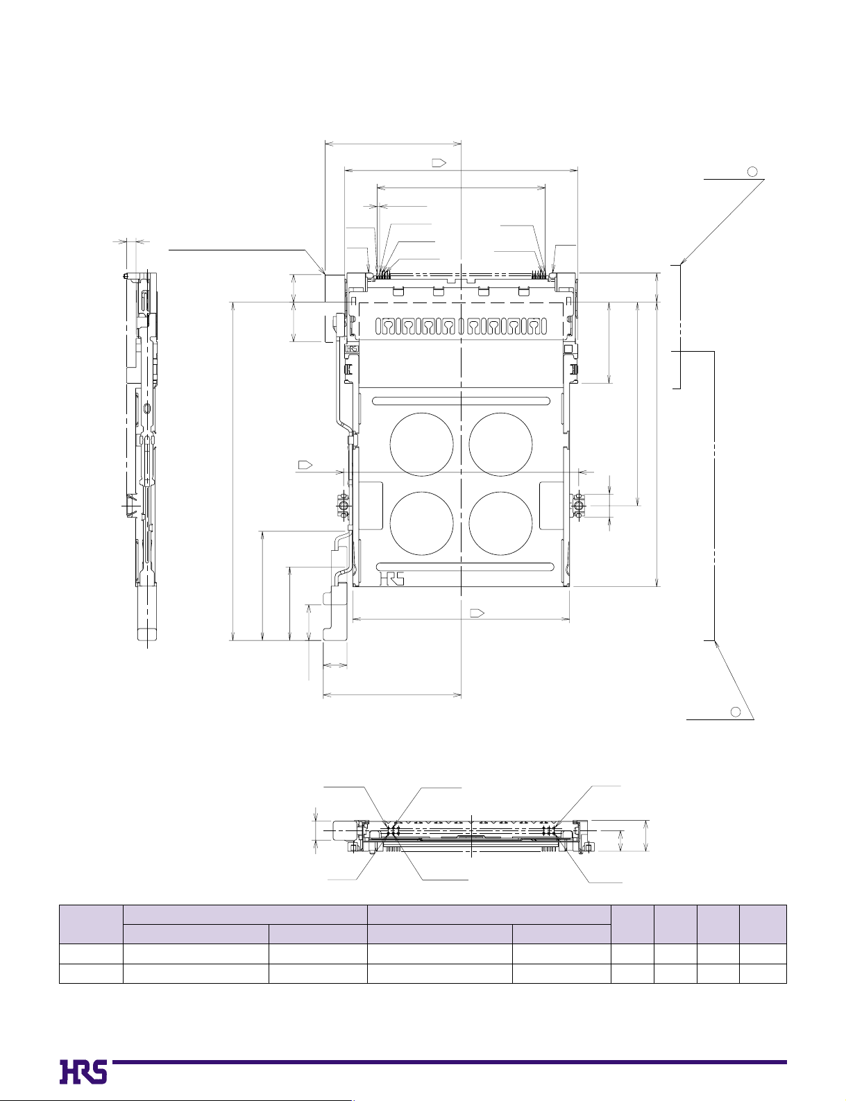
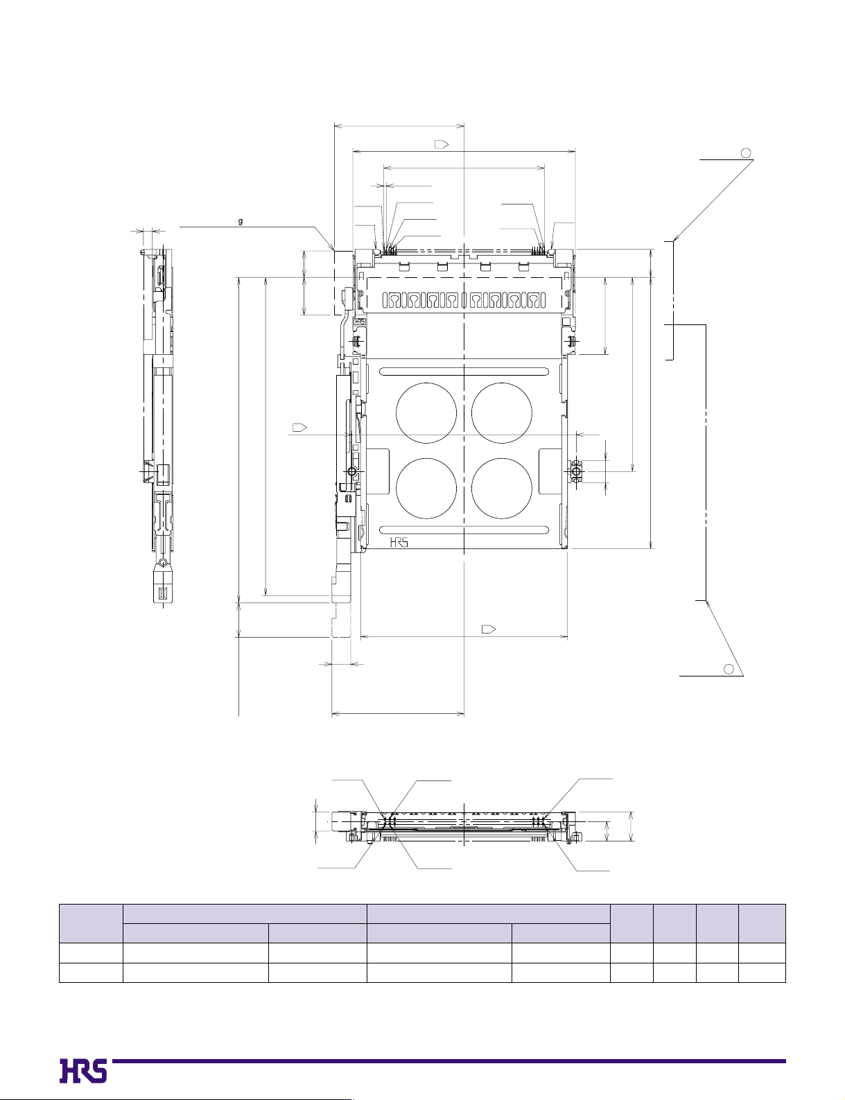
Note.3) Indicated dimensions are symmetrical to the center of the card insertion slot.
■Standard
Left rigid button type
Standoff
type
none
2.2mm
640-1008-6
640-1010-8
IC11S-68PL-1.27SF-EJL
IC11SA-68PL-1.27SF-EJL
640-1072-5
640-1074-0
IC11S-BD-EJL
IC11SA-BD-EJL
3
5.2
5.6
7.8
0.1
2.3
12.7
13.1
➀
SMT unit
CL No.Part Number
➁
Guide unit
A
(mm)B(mm)C(mm)
Weight
(g)
CL No.Part Number
C
eject metal fittings movable range
No.1
GND
34.4MAX
P= 0.635
No.35
No.2
No.36
3
59
42.545
No.68
No.34
GND
SMT unit ( )
1
7MAX
10MAX
85.6: in card insertion
(27.6)
(18.6)
3
59.5
stroke:9
7.472
A
20.5
P U S H
P U S H
51.5
5.9
3
54.9
6
( 34.9)
No.1
4.8
No.35
No.2
No.36
No.34
B
A
No.68
guide unit ( )
2
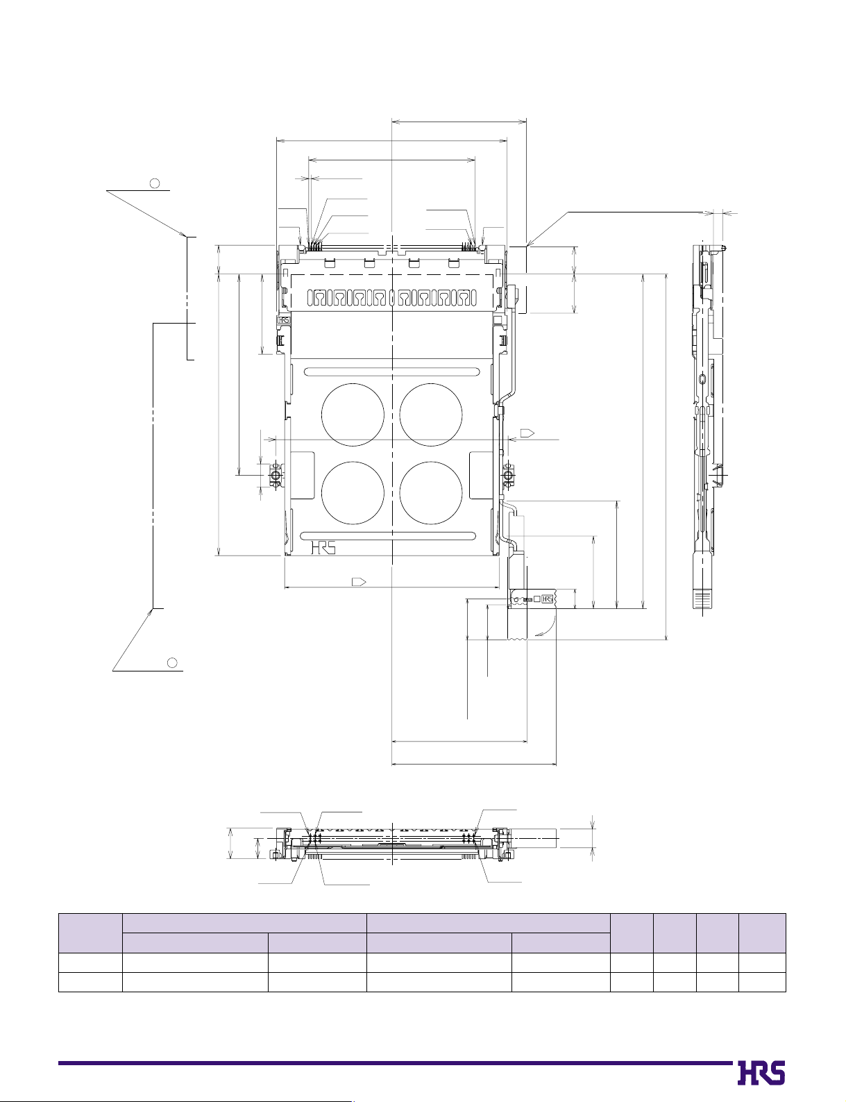
A7
Note.1) This figure illustrates grouping of SMT unit(➀) and guide unit(➁) together.
Note.2) Dimensions for card fitting are in accordance with "PC Card Standard".
Note.3) Indicated dimensions are symmetrical to the center of the card insertion slot.
■Standard
Right flexible button type
Standoff
type
none
2.2mm
640-1007-3
640-1009-9
IC11S-68PL-1.27SF-EJR
IC11SA-68PL-1.27SF-EJR
640-1075-3
640-1077-9
IC11S-BD-FEJR
IC11SA-BD-FEJR
3
5.2
5.6
7.8
0.1
2.3
13.1
13.5
➀
SMT unit
CL No.Part Number
➁
Guide unit
A
(mm)B(mm)C(mm)
Weight
(g)
CL No.Part Number
SMT unit ( )
1
No.1
GND
P=0.635
No.35
No.2
No.36
42.545
34.4 MAX
59
No.68
No.34
GND
eject metal fittings movable range
C
guide unit ( )
2
7.4
72
51.5
20.5
5.9
P U S H
7MAX
59.5
A
10MAX
(18.6)
5
85.6: in card insertion
(27.6)
(93.6): in card ejection
A
P U S H
3
3
54.9
stroke:9
button thrust volume(10.5)
(34.55)
(42.05)
No.34
No.68
B
A
No.1
No.35
No.2
No.36
4.8
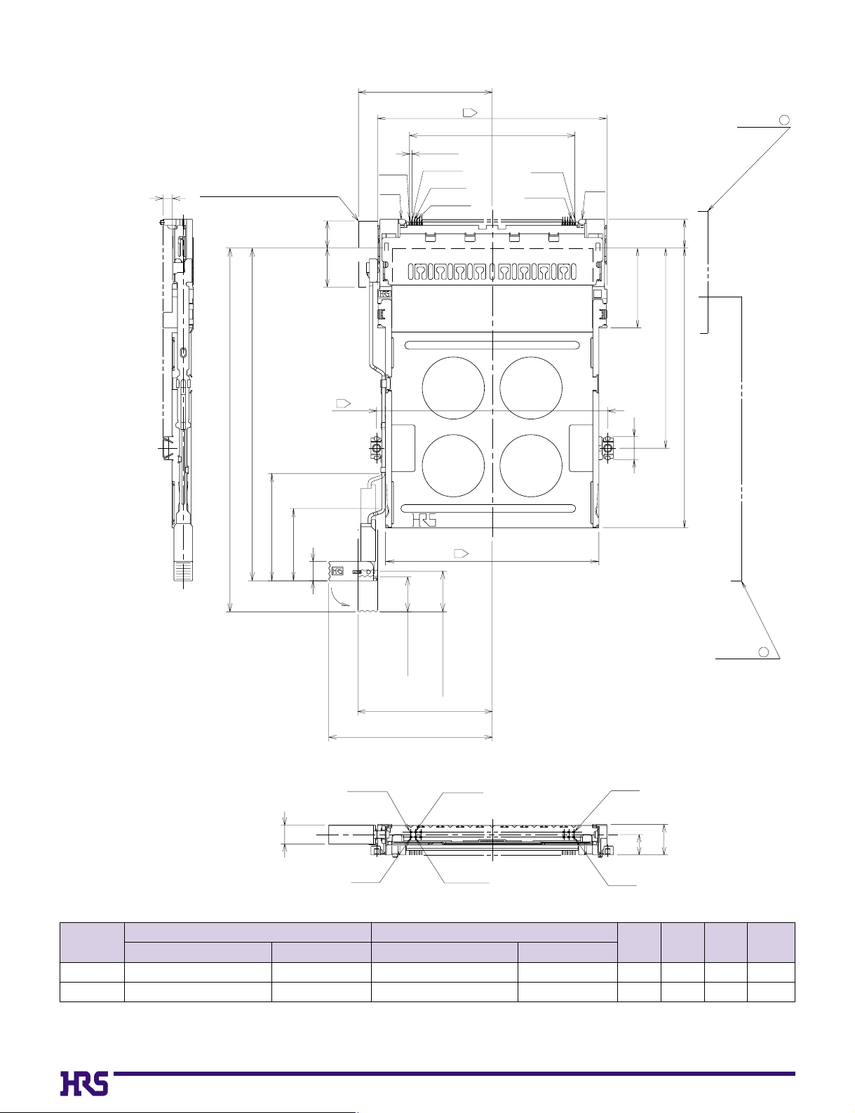
A8
Note.1) This figure illustrates grouping of SMT unit(➀) and guide unit(➁) together.
Note.2) Dimensions for card fitting are in accordance with "PC Card Standard".
Note.3) Indicated dimensions are symmetrical to the center of the card insertion slot.
■Standard
Left flexible. button type
Standoff
type
none
2.2mm
640-1008-6
640-1010-8
IC11S-68PL-1.27SF-EJL
IC11SA-68PL-1.27SF-EJL
640-1076-6
640-1078-1
IC11S-BD-FEJL
IC11SA-BD-FEJL
3
5.2
5.6
7.8
0.1
2.3
13.1
13.5
➀
SMT unit
CL No.Part Number
➁
Guide unit
A
(mm)B(mm)C(mm)
Weight
(g)
CL No.Part Number
eject metal fittings movable range
C
No.1
GND
34.4MAX
P=0.635
No.35
No.2
No.36
3
42.545
59
No.68
No.34
GND
SMT unit ( )
1
85.6: in card insertion
(93.6): in card ejection
(27.6)
(18.6)
51.5
7.472
guide unit ( )
2
7 MAX10 MAX
A
20.5
P U S H
P U S H
3
59.5
5.9
3
54.9
5
stroke:9
button thrust volume(10.5)
(34.55)
(42.05)
4.8
No.1
No.35
No.2 No.34
No.36
B
A
No.68
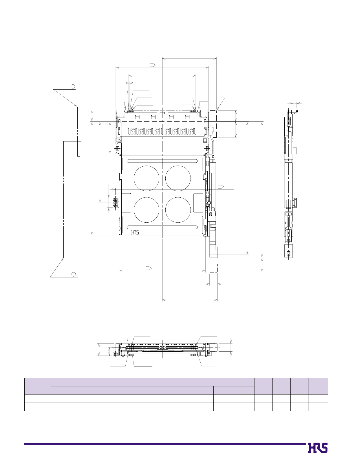
A9
■Standard
Right POP-UP button type
Standoff
type
none
2.2mm
640-1007-3
640-1009-9
IC11S-68PL-1.27SF-EJR
IC11SA-68PL-1.27SF-EJR
640-1081-6
640-1083-1
IC11S-BD-PEJR
IC11SA-BD-PEJR
3
5.2
5.7
7.9
0.1
2.3
14.7
15.1
➀
SMT unit
CL No.Part Number
➁
Guide unit
A
(mm)B(mm)C(mm)
Weight
(g)
CL No.Part Number
Note.1) This figure illustrates grouping of SMT unit(➀) and guide unit(➁) together.
Note.2) Dimensions for card fitting are in accordance with "PC Card Standard".
Note.3) Indicated dimensions are symmetrical to the center of the card insertion slot.
SMT unit ( )
1
guide unit ( )
2
eject metal fittings movable range
84.5(button thrust position)
86.4(button stored position)
9.1(Pop-up volume)
DR
No.35
No.36
No.2
No.1
No.68
No.34
72 7.4
51.5
20.5
5.9
54.9
GND
No.68
No.34
59
No.2
No.35
No.36
GND
No.1
P U S H
P U S H
B
A
5
(35.1)
5
59.5
10MAX
7MAX
C
34.4 MAX
42.545
P= 0.635
A
A
3
3
3
A10
■Standard
Left POP-UP button type
Standoff
type
none
2.2mm
640-1008-6
640-1010-8
IC11S-68PL-1.27SF-EJL
IC11SA-68PL-1.27SF-EJL
640-1082-9
640-1084-4
IC11S-BD-PEJL
IC11SA-BD-PEJL
3
5.2
5.7
7.9
0.1
2.3
14.7
15.1
➀
SMT unit
CL No.Part Number
➁
Guide unit
A
(mm)A(mm)C(mm)
Weight
(g)
CL No.Part Number
Note.1) This figure illustrates grouping of SMT unit(➀) and guide unit(➁) together.
Note.2) Dimensions for card fitting are in accordance with "PC Card Standard".
Note.3) Indicated dimensions are symmetrical to the center of the card insertion slot.
SMT unit ( )
1
guide unit ( )
2
eject metal fittings movable range
86.4(button stored position)
84.5(button thrust position)
9.1(Pop-up volume)
DL
No.1
No.35
No.2
No.36
No.68
No.34
54.9
72 7.4
51.5
20.5
5.9
GND
No.34
No.68
No.36
No.35
No.2
No.1
GND
59
C
5
B
A
5
(35.1)
59.5
P= 0.635
42.545
34.4 MAX
7MAX
10MAX
A
P U S H
P U S H
3
3
3
A11
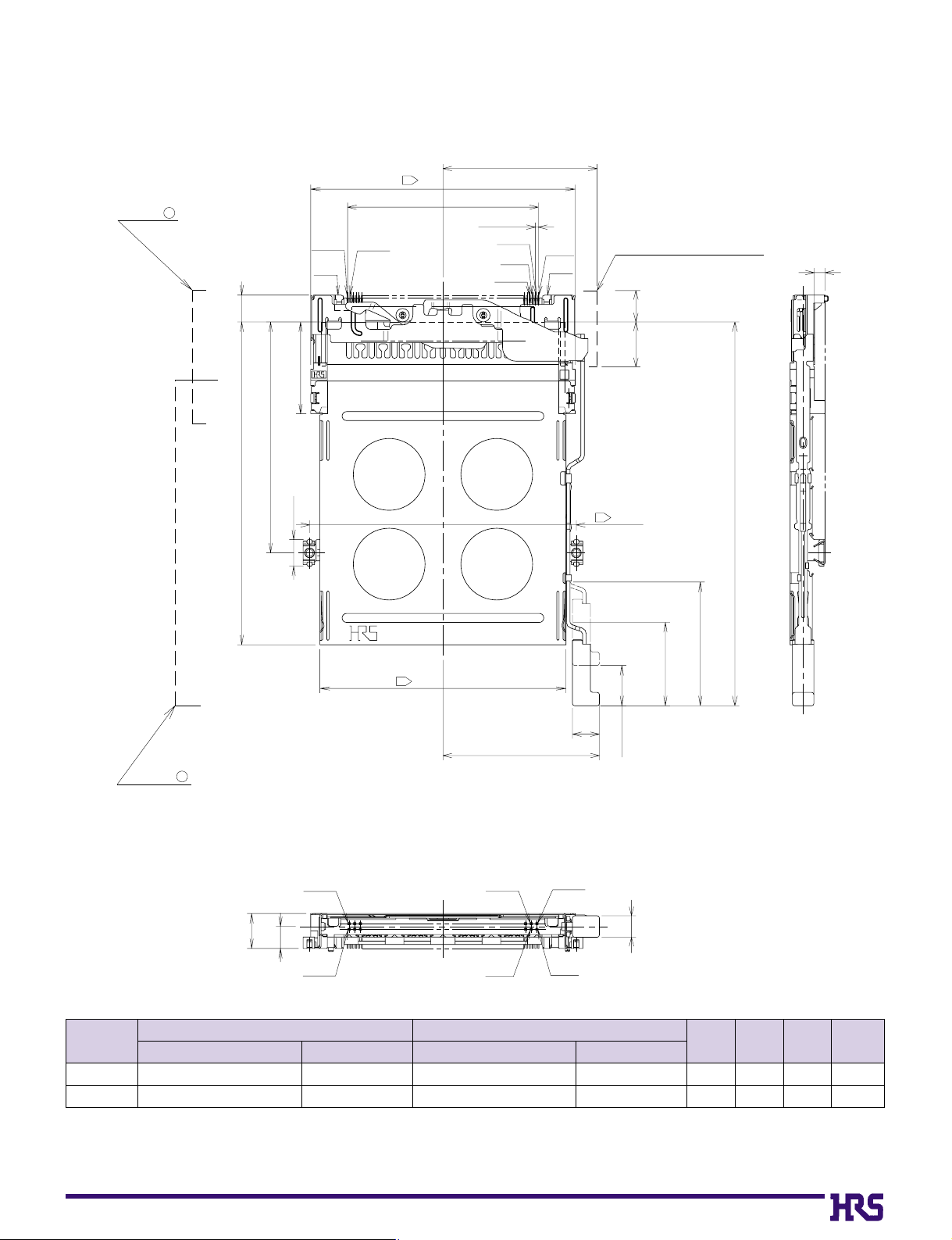
Note.1) This figure illustrates grouping of SMT unit(➀) and guide unit(➁) together.
Note.2) Dimensions for card fitting are in accordance with "PC Card Standard".
Note.3) Indicated dimensions are symmetrical to the center of the card insertion slot.
■Reverse
Right rigid button type
Standoff
type
none
2.2mm
640-1003-2
640-1005-8
IC11S-68PLR-1.27SF-EJR
IC11SA-68PLR-1.27SF-EJR
640-1055-6
640-1057-1
IC11S-BUR-EJR
IC11SA-BUR-EJR
2.7
4.9
5.6
7.8
0.1
2.3
13.1
13.6
➀
SMT unit
CL No.Part Number
➁
Guide unit
A
(mm)B(mm)C(mm)
Weight
(g)
CL No.Part Number
SMT unit ( )
1
No.68
GND
No.34
3
59
42.545
34.4 MAX
P=0.635
No.35
No.2
No.36
No.1
GND
eject metal fittings movable range
C
guide unit ( )
2
672
A
P U S H
6
51.5
5.9
20.5
P U S H
3
54.9
(34.9)
3
7MAX
10MAX
59.5
85.6: in card insertion
(27.6)
(18.6)
stroke:9
B
A
No.68
No.34
No.36
No.2
No.35
No.1
4.8
A12
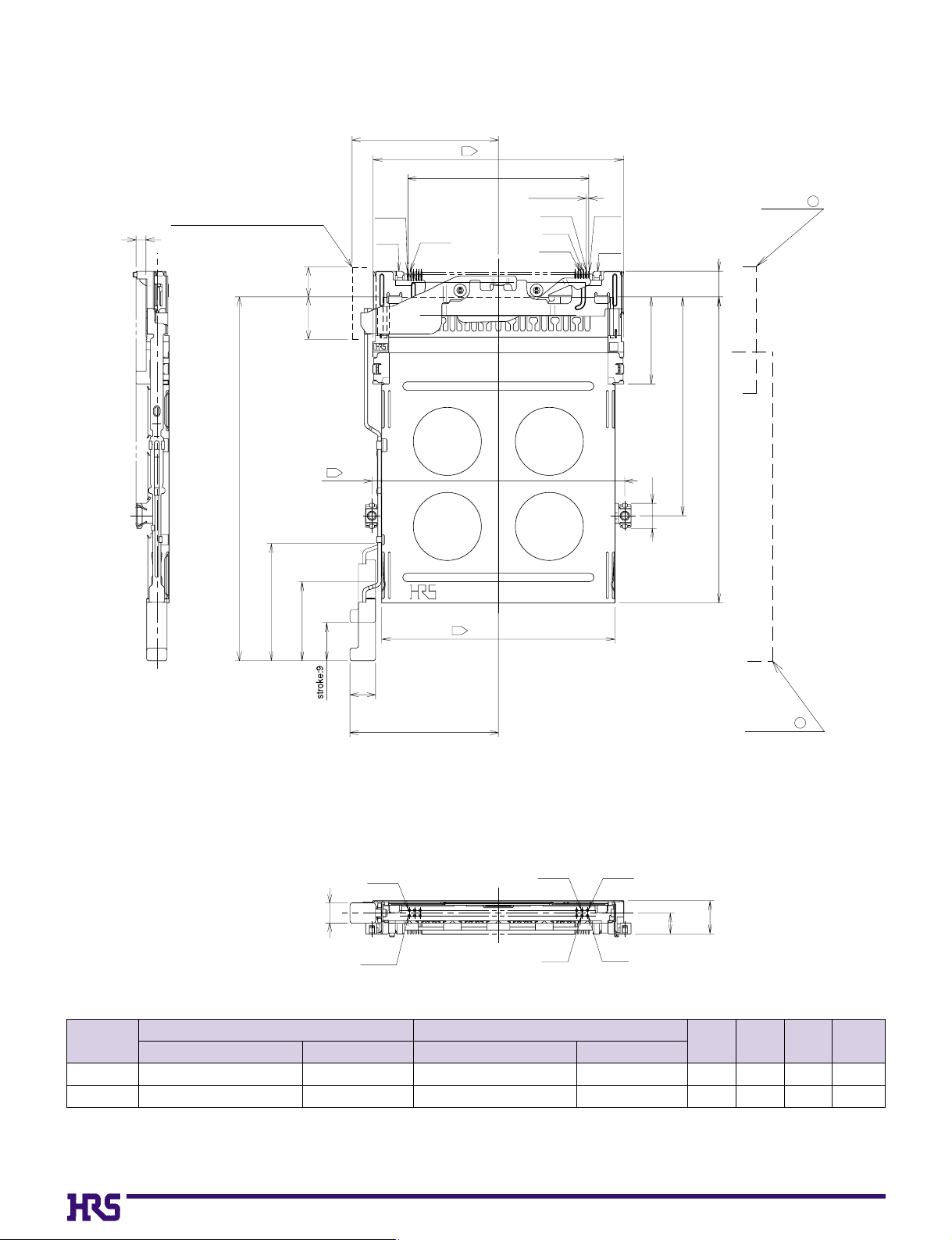
Note.1) This figure illustrates grouping of SMT unit(➀) and guide unit(➁) together.
Note.2) Dimensions for card fitting are in accordance with "PC Card Standard".
Note.3) Indicated dimensions are symmetrical to the center of the card insertion slot.
■Reverse
Left rigid button type
Standoff
type
none
2.2mm
640-1004-5
640-1006-0
IC11S-68PLR-1.27SF-EJL
IC11SA-68PLR-1.27SF-EJL
640-1056-9
640-1058-4
IC11S-BUR-EJL
IC11SA-BUR-EJL
2.7
4.9
5.6
7.8
0.1
2.3
13.1
13.6
➀
SMT unit
CL No.Part Number
➁
Guide unit
A
(mm)B(mm)C(mm)
Weight
(g)
CL No.Part Number
eject metal fittings movable range
C
No.68
GND
34.4 MAX
No.34
3
42.545
59
P= 0.635
No.35
No.2
No.36
No.1
GND
SMT unit ( )
1
7MAX
10MAX
85.6: in card insertion
(27.6)
(18.6)
6
A
20.5
P U S H
P U S H
51.5
72
3
59.5
5.9
3
54.9
6
(34.9)
guide unit ( )
2
No.68
4.8
No.34
No.36
No.2
No.35
No.1
B
A
A13
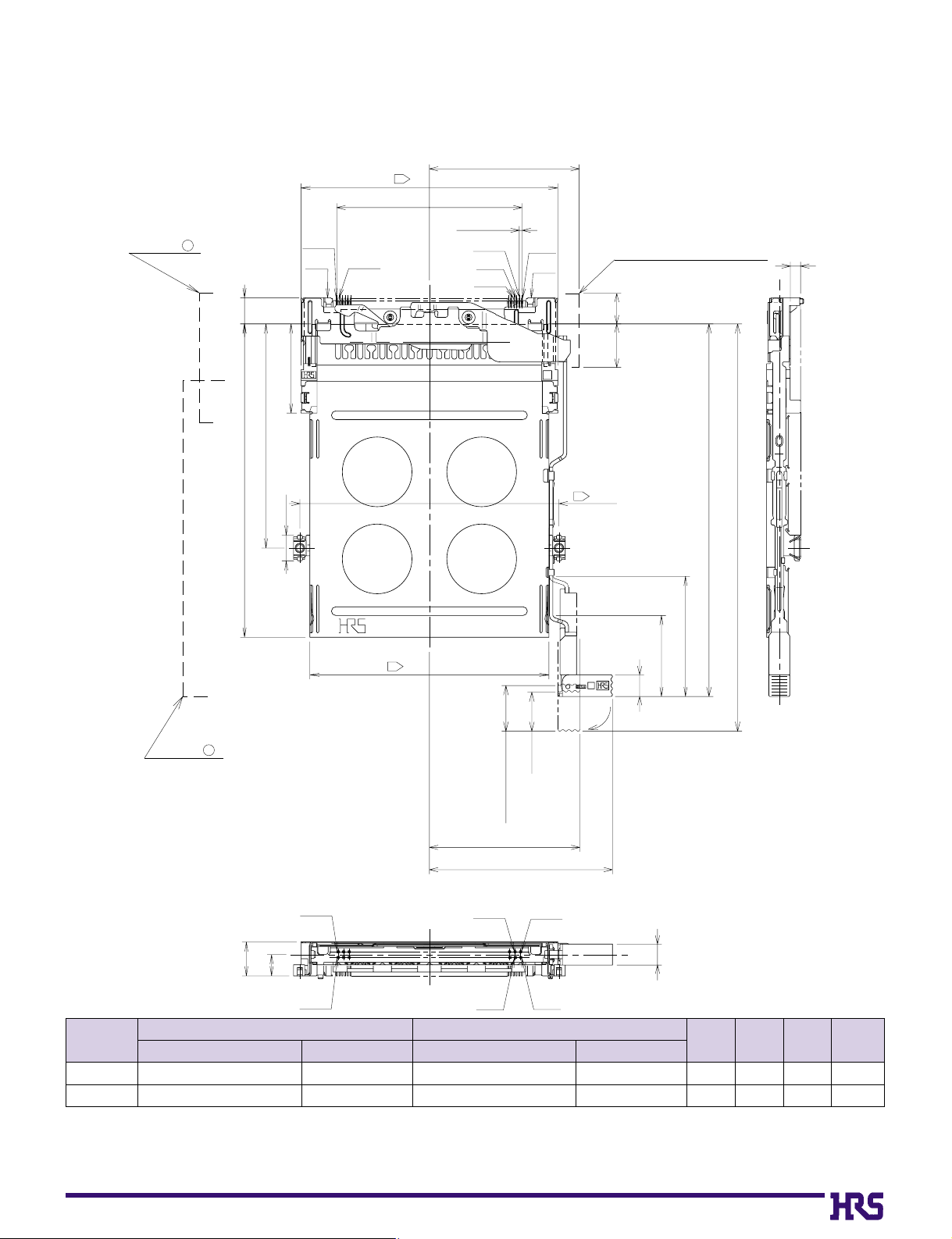
Note.1) This figure illustrates grouping of SMT unit(➀) and guide unit(➁) together.
Note.2) Dimensions for card fitting are in accordance with "PC Card Standard".
Note.3) Indicated dimensions are symmetrical to the center of the card insertion slot.
■Reverse
Right flexible button type
Standoff
type
none
2.2mm
640-1003-2
640-1005-8
IC11S-68PLR-1.27SF-EJR
IC11SA-68PLR-1.27SF-EJR
640-1059-7
640-1061-9
IC11S-BUR-FEJR
IC11SA-BUR-FEJR
2.7
4.9
5.6
7.8
0.1
2.3
13.5
14
➀
SMT unit
CL No.Part Number
➁
Guide unit
A
(mm)B(mm)C(mm)
Weight
(g)
CL No.Part Number
SMT unit ( )
1
No.68
GND
No.34
3
42.545
34.4 MAX
59
P= 0.635
No.35
No.2
No.36
No.1
GND
eject metal fittings movable range
C
guide unit ( )
2
6
20.5
P U S H
51.5
72
5.9
3
54.9
A
P U S H
stroke:9
7MAX
10MAX
3
59.5
93.6: in card ejection
85.6: in card insertion
(27.6)
(18.6)
A
5
button thrust :(10.5)
( 34.55)
( 42.05)
No.68
B
A
No.34
No.36
No.2
No.35
No.1
4.8
 Loading...