

HRS HIF3B Service Manual
B15
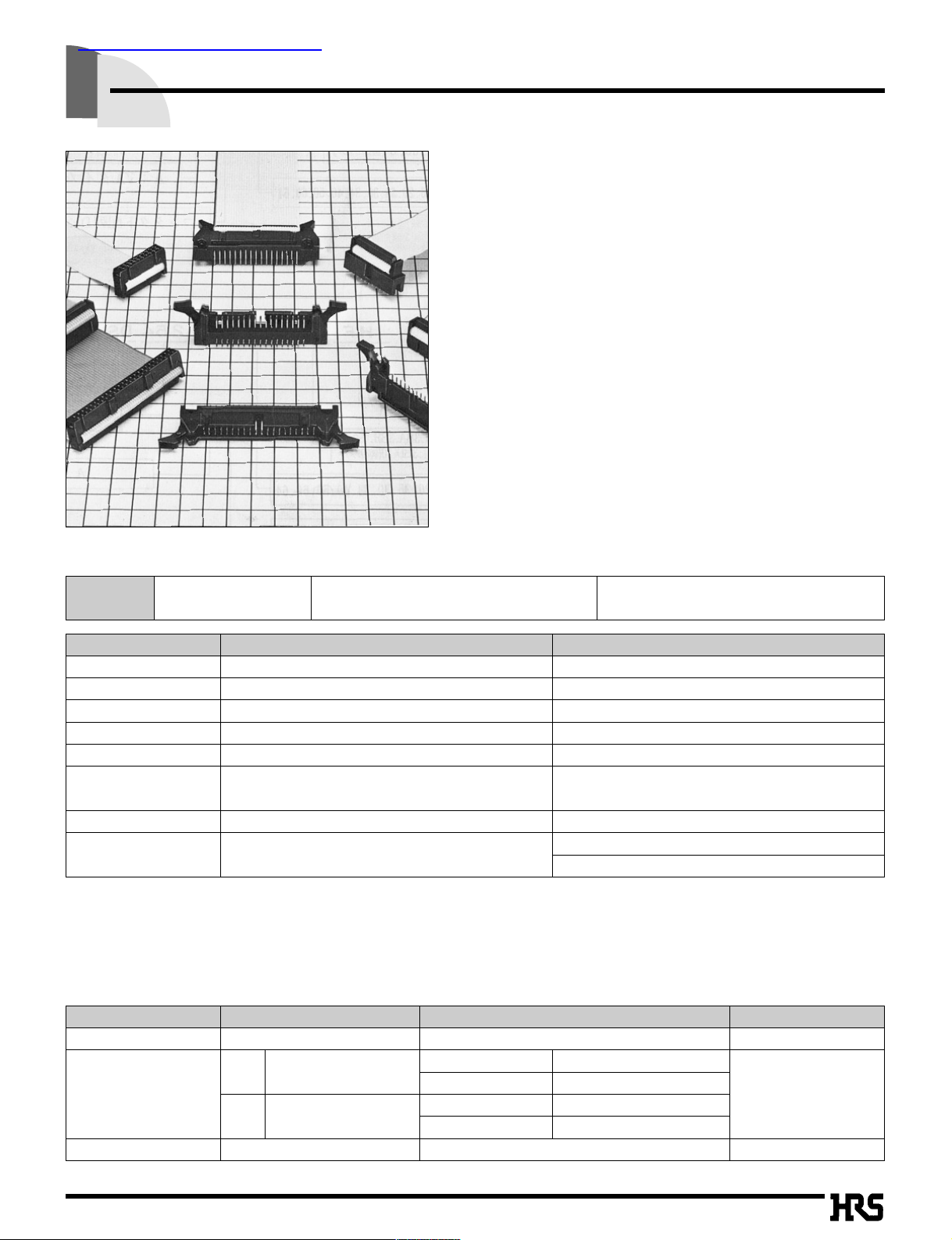
Ribbon Cable connector Compliant with MIL Standard
HIF3B Series
■Features
1. Product Compliant with MIL Standard
HIF3B series has been developed as a product compliant with MIL
standard, and used for wide applications.
2. UL Approval Product
HIF3B series connectors are UL approved.
3. Mechanism to Prevent Mis-insertion
This connector is equipped with the mechanism to prevent Misinsertion as follows.
1 The system provides the convex area to insert the guide-key on the
pin header side, and to guide it in combination with the socket
convex area (MIL standard).
2
The system embeds and guides the polarizing key in the socket holes.
4. Applicable Cable AWG#28
The applicable cable is UL2651 AWG#28 flat cable (7 cores./
0.127mm, jacket dia. 0.9±0.1mm).
■Product Specifications
Note 1: Includes temperature rise caused by current flow.
Note 2: The term "storage" refers to products stored for long period of time prior to mounting and use. Operating Temperature Range and
Humidity range covers non conducting condition of installed connectors in storage, shipment or during transportation.
Rating
Current rating : 1A
Operating Temperature Range
:
–55 to +85ç(Note 1)Storage Temperature Range : –10 to +60ç(Note 2
)
Voltage rating : 200V AC Operating Moisture Range : 40 to 80% Storage Humidity Range : 40 to 70% (Note 2
)
Item Specification Condition
1. Insulation Resistance 1000M ohms min. 500V DC
2. Withstanding voltage
No flashover or insulation breakdown.
650V AC/1 minute
3. Contact Resistance 15m ohms max. 0.1A
4.
Vibration
No electrical discontinuity of 1µs or more
Frequency: 10 to 55 Hz, single amplitude of 0.75 mm, 2 hours in each of the 3 directions.
5.
Humidity (Steady state)
Insulation resistance: 1000M ohms min.
96 hours at temperature of 40ç and humidity of 90% to 95%
6. Temperature Cycle No damage, cracks, or parts looseness.
(-65ç: 30 minutes ➝ 15 to 35ç: 5 minutes max.
125ç: 30 minutes ➝ 15 to 35ç: 5 minutes max.) 5 cycles
7.
Durability (Mating/un-mating)
Contact resistance: 15m ohms max. 500 cycles
8.
Resistance to Soldering heat
No deformation of components affecting performance.
Flow: 260ç for 10 seconds
Manual soldering: 300ç for 3 seconds
■Material
Part Material Finish Remarks
Insulator PBT Black UL94V-0
D Beryllium copper
Connection area Gold plated
Socket Contact
Connection area Gold plated
–––––––
DA Copper alloy
Connection area Gold plated
Connection area Tin lead plated
Pin header contact Brass Selective Gold plated –––––––
查询HIF3B-16DA-2.54R供应商
B16
■Ordering Information
HIF 3B - * D A - 2.54 R
qw ret yu
q Series Name : HIF
w Series No. : 3B, 3BA, 3BB (50, 60, 64 contacts only
)
e
Number of contacts
: 16, 20, 26, 30, 34, 40, 50, 60, 64
r
Contact alignment
: D : Double
t A : VA type
y Contact pitch : 2.54mm
u Connection type
R : ID type
●Socket
HIF 3B - * P A - 2.54 DS
qw ret yu
q Series Name : HIF
w Series No. :
3B :
(14 contacts not included)
3BC: (10 contacts only)
3BA, 3BB: (50, 60, 64 contacts only) 3BD: (10 contacts only)
e
Number of contacts
: 16, 20, 26, 30, 34, 40, 50, 60, 64
r P : Pin header
t A : Selective gold plated
y Contact pitch : 2.54mm
u Contact style
DS : Right angle type
DSA : Straight type
●Pin Header
B17
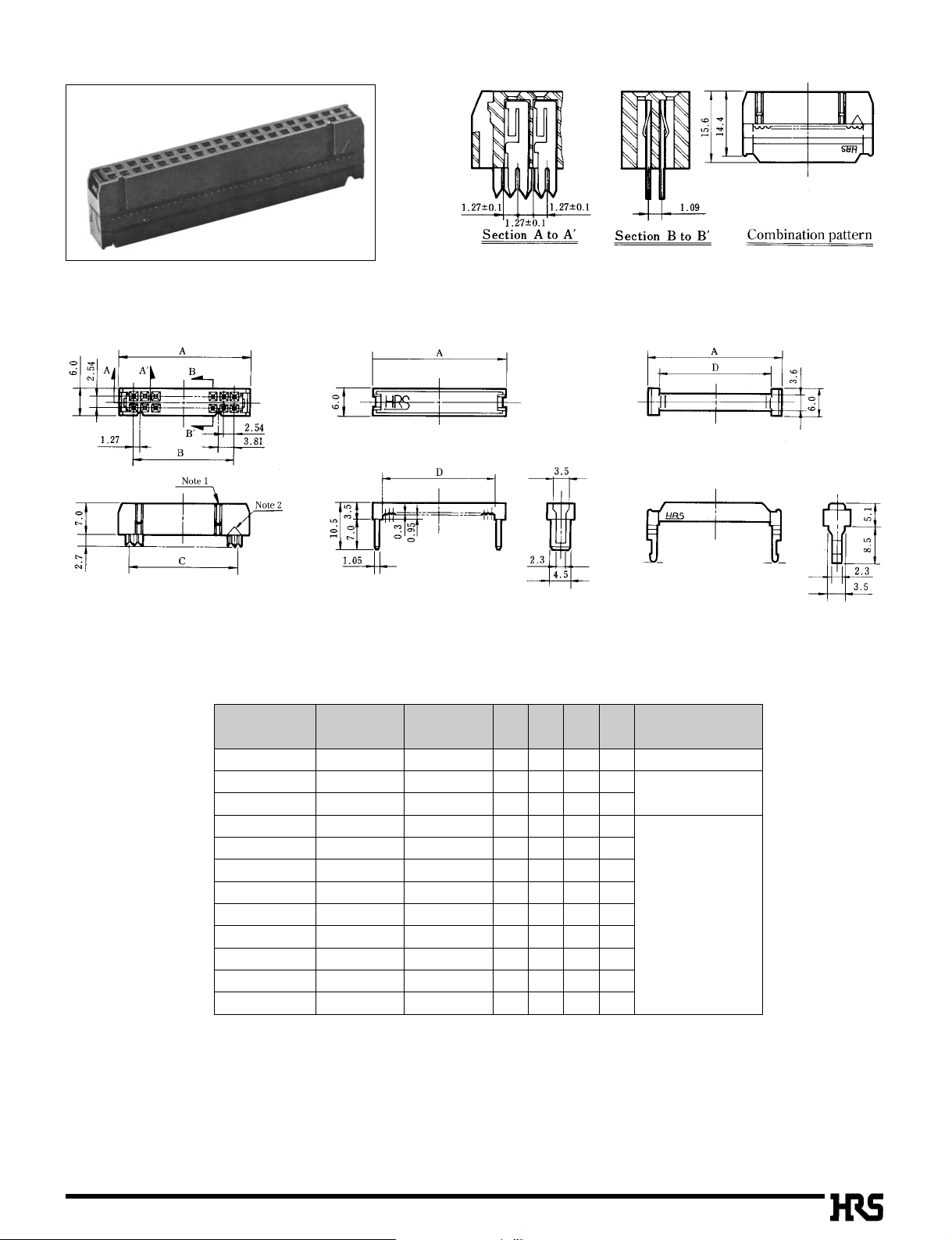
■Socket (With guide to prevent mis-insertion)
Unit:mm
★
★
★
★
★
★
★
★
★
★
★
★
★
Note1, Note2: The number of polarizing keys and polarizing keyways changes according to products. Refer to the list as shown below.
Note3: The 50, 60 and 64 contact connector contain two types of polarizing guides. Use the products, referring to Notes 1 and 2.
Note4: The 6 contact has no polarizing mark.
The products marked with ★comply with MIL standard.
Body Protector Clamp
CL No.Part Number
610-0032-3
610-0021-7
610-0022-0
610-0023-2
610-0024-5
610-0025-8
610-0026-0
610-0027-3
610-0028-6
610-0029-9
610-0041-4
610-0030-8
610-0042-7
610-0031-0
610-0043-0
HIF3BA- 6D-2.54R
HIF3BA-10D-2.54R
HIF3BA-14D-2.54R
HIF3BA-16D-2.54R
HIF3BA-20D-2.54R
HIF3BA-26D-2.54R
HIF3BA-30D-2.54R
HIF3BA-34D-2.54R
HIF3BA-40D-2.54R
HIF3BA-50D-2.54R
HIF3BB-50D-2.54R
HIF3BA-60D-2.54R
HIF3BB-60D-2.54R
HIF3BA-64D-2.54R
HIF3BB-64D-2.54R
Number of Contacts
6
10
14
16
20
26
30
34
40
50
50
60
60
64
64
A
12.19
17.27
22.35
24.89
29.97
37.59
42.67
47.75
55.37
68.07
68.07
80.77
80.77
85.85
85.85
CL No.Part Number
–––––––
610-0651-5
610-0652-8
610-0653-0
610-0654-3
610-0655-6
610-0656-9
610-0657-1
610-0658-4
610-0659-7
610-0671-2
610-0660-6
610-0672-5
610-0661-9
610-0673-8
HIF3BA-10DA-2.54R
HIF3BA-14DA-2.54R
HIF3BA-16DA-2.54R
HIF3BA-20DA-2.54R
HIF3BA-26DA-2.54R
HIF3BA-30DA-2.54R
HIF3BA-34DA-2.54R
HIF3BA-40DA-2.54R
HIF3BA-50DA-2.54R
HIF3BB-50DA-2.54R
HIF3BA-60DA-2.54R
HIF3BB-60DA-2.54R
HIF3BA-64DA-2.54R
HIF3BB-64DA-2.54R
B
5.08
10.16
15.24
17.78
22.86
30.48
35.56
40.64
48.26
60.96
60.96
73.66
73.66
78.74
78.74
C
6.35
11.43
16.51
19.05
24.13
31.75
36.83
41.91
49.53
62.23
62.23
74.93
74.93
80.01
80.01
D
7.72
12.8
17.88
20.42
25.5
33.12
38.2
43.28
50.9
63.6
63.6
76.3
76.3
81.38
81.38
Polarizing Guide
(Note 1)
One at center
One on right and left sides, resp.
One at center
One on right and left sides, resp.
One at center
One on right and left sides, resp.
One at center
Polarizing Keyway
(Note 2)
None
One on left side
One on right and
left sides, resp.
B18
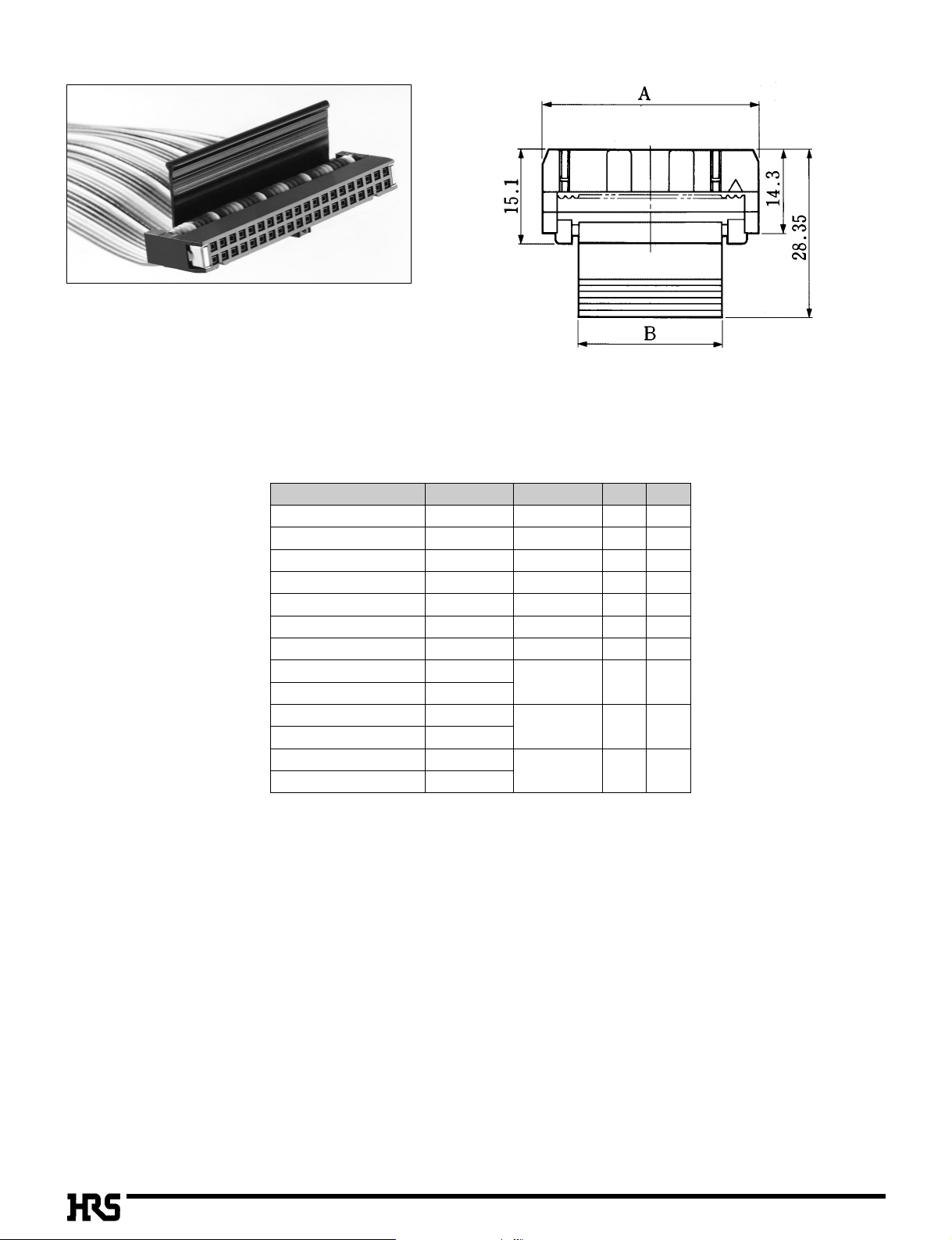
■Socket with Withdrawal Tab
Part Number CL No.
Unit : mm
HIF3BA-10D-2.54R-CL
HIF3BA-16D-2.54R-CL
HIF3BA-20D-2.54R-CL
HIF3BA-26D-2.54R-CL
HIF3BA-30D-2.54R-CL
HIF3BA-34D-2.54R-CL
HIF3BA-40D-2.54R-CL
HIF3BA-50D-2.54R-CL
HIF3BB-50D-2.54R-CL
HIF3BA-60D-2.54R-CL
HIF3BB-60D-2.54R-CL
HIF3BA-64D-2.54R-CL
HIF3BB-64D-2.54R-CL
610-0190-4
610-0192-0
610-0193-2
610-0194-5
610-0195-8
610-0196-0
610-0197-3
610-0198-6
610-0201-9
610-0199-9
610-0202-1
610-0200-6
610-0203-4
Number of Contacts
10
16
20
26
30
34
40
50
60
64
A B
17.27
24.89
29.97
37.59
42.67
47.75
55.37
68.07
80.77
85.85
5.3
12.9
18.0
25.5
30.5
35.8
43.4
56.0
68.5
73.8
B19
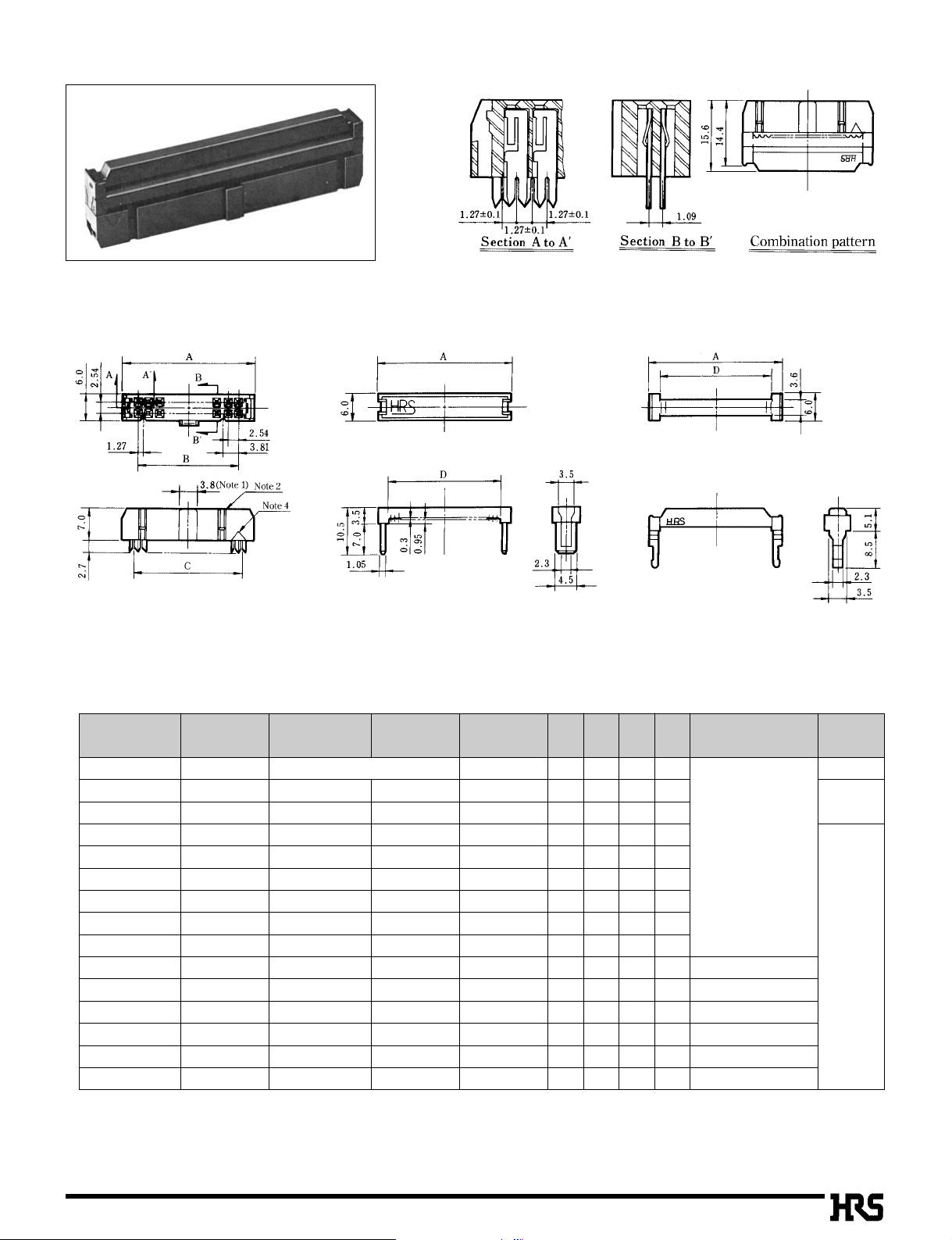
■Socket
Note1: The number of polarizing keys and polarizing keyways changes according to products. For details, refer to the list as shown below.
Note2: The 6 contact has no polarizing mark.
Body Protector Clamp
Unit:mm
★
★
★
★
★
★
★
★
★
★
★
The products marked with ★comply with MIL standard.
CL No.Part Number
610-0012-6
610-0001-0
610-0002-2
610-0003-5
610-0004-8
610-0005-0
610-0006-3
610-0007-6
610-0008-9
610-0009-1
610-0010-0
610-0011-3
HIF3B- 6D-2.54R
HIF3B-10D-2.54R
HIF3B-14D-2.54R
HIF3B-16D-2.54R
HIF3B-20D-2.54R
HIF3B-26D-2.54R
HIF3B-30D-2.54R
HIF3B-34D-2.54R
HIF3B-40D-2.54R
HIF3B-50D-2.54R
HIF3B-60D-2.54R
HIF3B-64D-2.54R
Number of Contacts
6
10
14
16
20
26
30
34
40
50
60
64
A
12.19
17.27
22.35
24.89
29.97
37.59
42.67
47.75
55.37
68.07
80.77
85.85
B
5.08
10.16
15.24
17.78
22.86
30.48
35.56
40.64
48.26
60.96
73.66
78.74
C
6.35
11.43
16.51
19.05
24.13
31.75
36.83
41.91
49.53
62.23
74.93
80.01
D
7.72
12.80
17.88
20.42
25.50
33.12
38.2
43.28
50.90
63.6
76.3
81.38
Polarizing Guide
(Note 1)
None
One on left side
One on right and
left sides, resp.
B20
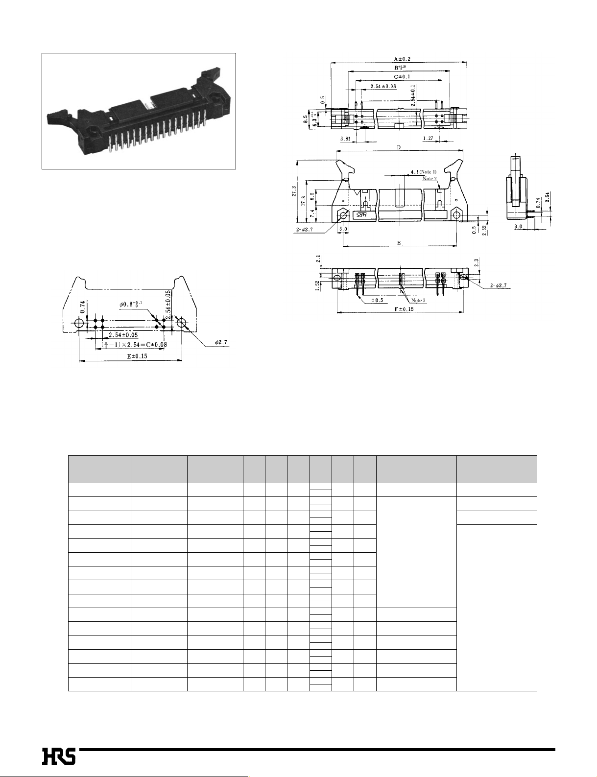
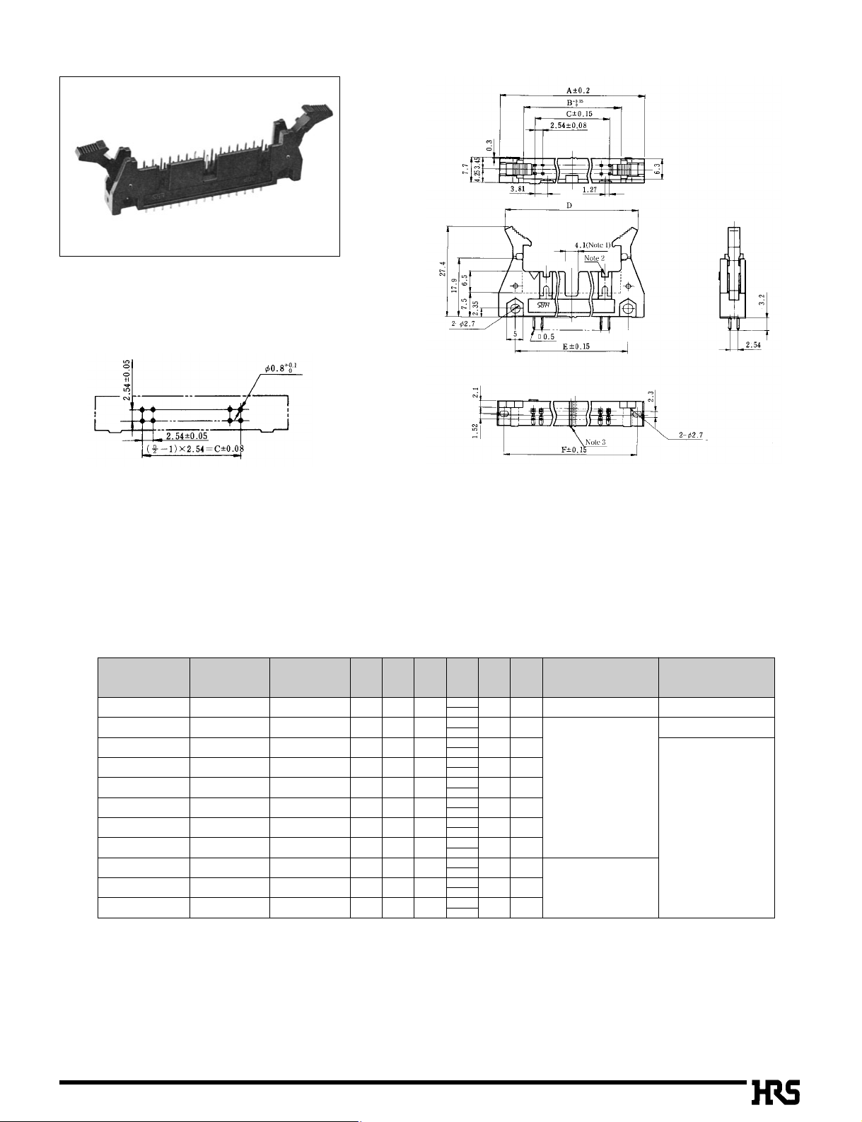
■Four Wall Angle Through hole
BPCB mounting pattern
Note 1, Note 2: The number of polarizing slot and key installed positions
changes according to products. Refer to the list as shown below.
Note 3: The spacer moves to the right according to the number of
contacts.
Note 4: The 10, 50, 60 and 64 contact connectors contain two types of
polarizing slots.
Use products, referring to (Note 1) (Note 2).
■
n=number of contacts
Unit:mm
★
★
★
★
★
★
★
★
★
★
★
★
★
★
The products marked with ★comply with MIL standard.
CL No.Part Number
610-0091-2
610-0171-0
610-0092-5
610-0093-8
610-0094-0
610-0095-3
610-0096-6
610-0097-9
610-0098-1
610-0099-4
610-0131-5
610-0100-1
610-0132-8
610-0101-4
610-0133-0
HIF3BA-10PA-2.54DS
HIF3BD-10PA-2.54DS
HIF3BA-14PA-2.54DS
HIF3BA-16PA-2.54DS
HIF3BA-20PA-2.54DS
HIF3BA-26PA-2.54DS
HIF3BA-30PA-2.54DS
HIF3BA-34PA-2.54DS
HIF3BA-40PA-2.54DS
HIF3BA-50PA-2.54DS
HIF3BB-50PA-2.54DS
HIF3BA-60PA-2.54DS
HIF3BB-60PA-2.54DS
HIF3BA-64PA-2.54DS
HIF3BB-64PA-2.54DS
Number of Contacts
10
10
14
16
20
26
30
34
40
50
50
60
60
64
64
A
32.0
32.0
37.1
39.6
44.7
52.3
57.4
62.5
70.1
82.8
82.8
95.5
95.5
100.6
100.6
B
17.5
17.5
22.6
25.1
30.2
37.8
42.9
48.0
55.6
68.3
68.3
81.0
81.0
86.1
86.1
C
10.16
10.16
15.24
17.78
22.86
30.48
35.56
40.64
48.26
60.96
60.96
73.66
73.66
78.74
78.74
E
21.8
21.8
26.9
29.5
34.5
42.2
47.2
52.3
59.9
72.6
72.6
85.3
85.3
90.4
90.4
27.9
27.9
33.0
35.5
40.6
48.3
53.3
58.4
66.0
78.7
78.7
91.4
91.4
96.5
96.5
F
Polarizing Slot
(Note 1)
None
One at center
One on right and left sides, resp.
One at center
One on right and left sides, resp.
One at center
One on right and left sides, resp.
One at center
Polarizing Key Install
(Note 2)
One on right side
None
One on right side
One on right and
left sides, resp.
D
28.14
MAX51.1
28.14
MAX51.1
33.24
MAX56.2
35.74
MAX58.7
40.84
MAX63.8
48.44
MAX71.4
53.54
MAX76.5
58.64
MAX81.6
66.24
MAX89.2
78.94
MAX101.9
78.94
MAX101.9
91.64
MAX114.6
91.64
MAX114.6
96.74
MAX119.7
96.74
MAX119.7
B21
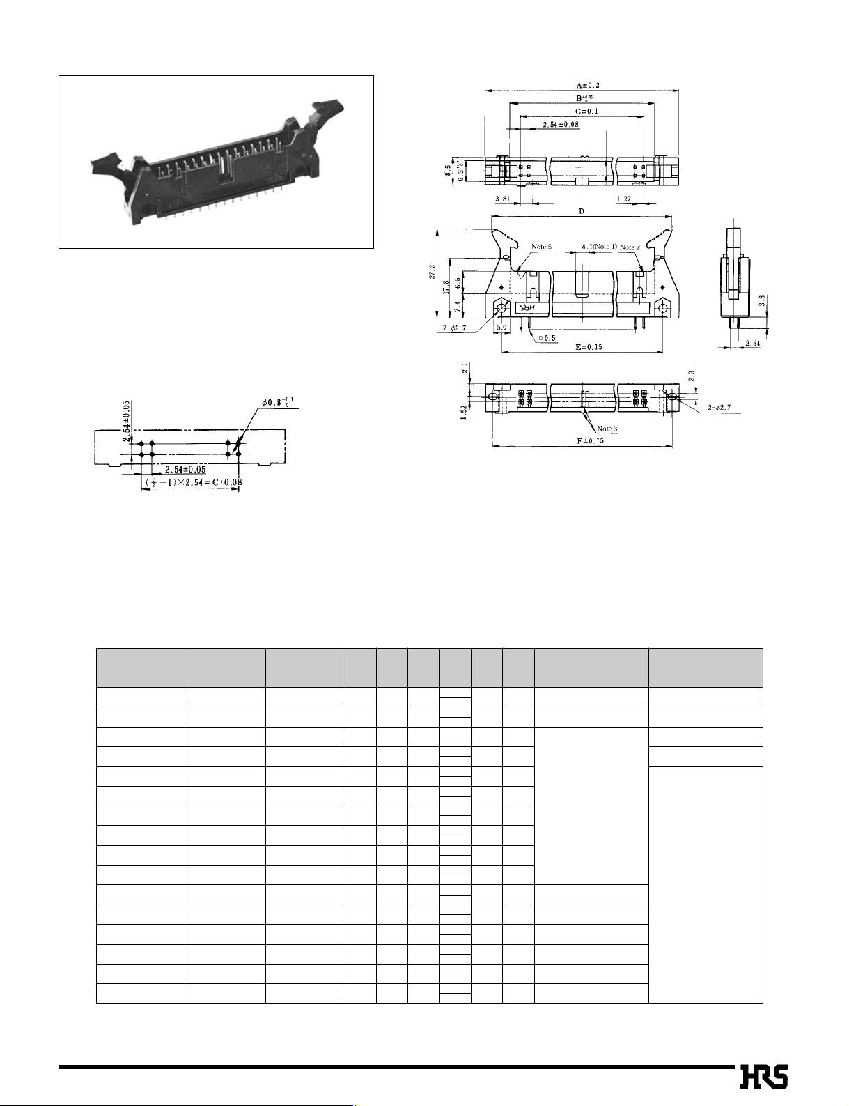
■Four-Wall Straight Through hole
BPCB mounting pattern
Note 1, Note 2: The number of polarizing slot and key installed positions
changes according to products. Refer to the list as shown below.
Note 3: The spacer moves to the right according to the number of
contacts.
Note 4: The 10, 50, 60 and 64 contact connectors contain two types of
polarizing slots.
Use products, confirming (Note 1) (Note 2).
Note 5: The 6 contact has no polarity mark.
■
n=number of contacts
Unit:mm
★
★
★
★
★
★
★
★
★
★
★
★
★
★
★
The products marked with ★comply with MIL standard.
CL No.Part Number
562-0503-9
610-0111-8
610-0181-3
610-0112-0
610-0113-3
610-0114-6
610-0115-9
610-0116-1
610-0117-4
610-0118-7
610-0119-0
610-0141-9
610-0120-9
610-0142-1
610-0121-1
610-0143-4
HIF3-6PA-2.54DSA
HIF3BA-10PA-2.54DSA
HIF3BD-10PA-2.54DSA
HIF3BA-14PA-2.54DSA
HIF3BA-16PA-2.54DSA
HIF3BA-20PA-2.54DSA
HIF3BA-26PA-2.54DSA
HIF3BA-30PA-2.54DSA
HIF3BA-34PA-2.54DSA
HIF3BA-40PA-2.54DSA
HIF3BA-50PA-2.54DSA
HIF3BB-50PA-2.54DSA
HIF3BA-60PA-2.54DSA
HIF3BB-60PA-2.54DSA
HIF3BA-64PA-2.54DSA
HIF3BB-64PA-2.54DSA
Number of Contacts
6
10
10
14
16
20
26
30
34
40
50
50
60
60
64
64
A
26.92
32.0
32.0
37.1
39.6
44.7
52.3
57.4
62.5
70.1
82.8
82.8
95.5
95.5
100.6
100.6
B
12.42
17.5
17.5
22.6
25.1
30.2
37.8
42.9
48.0
55.6
68.3
68.3
81.0
81.0
86.1
86.1
C
05.08
10.16
10.16
15.24
17.78
22.86
30.48
35.56
40.64
48.26
60.96
60.96
73.66
73.66
78.74
78.74
E
16.7
21.8
21.8
26.9
29.5
34.5
42.2
47.2
52.3
59.9
72.6
72.6
85.3
85.3
90.4
90.4
22.82
27.9
27.9
33.0
35.5
40.6
48.3
53.3
58.4
66.0
78.7
78.7
91.4
91.4
96.5
96.5
F
Polarizing Slot
(Note 1)
One at center
None
One at center
One on right and left sides, resp.
One at center
One on right and left sides, resp.
One at center
One on right and left sides, resp.
One at center
Polarizing Key Install
(Note 2)
None
One on right side
None
One on right side
One on right and
left sides, resp.
D
23.06
MAX46.02
28.14
MAX51.1
28.14
MAX51.1
33.24
MAX56.2
35.74
MAX58.7
40.84
MAX63.8
48.44
MAX71.4
53.54
MAX76.5
58.64
MAX81.6
66.24
MAX89.2
78.94
MAX101.9
78.94
MAX101.9
91.64
MAX114.6
91.64
MAX114.6
96.74
MAX119.7
96.74
MAX119.7
B22
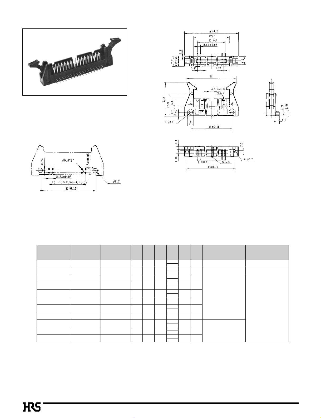
■Three Wall Angle Type
BPCB mounting pattern
Note 1, Note 2: The number of polarizing slot and key installed positions
changes according to products. Refer to the list as shown below.
Note 3: The spacer moves according to the number of contacts.
Note 4: The 10 contact connector consists of two types.
Use products, confirming (Note 1) (Note 2).
Note 5: The 6 contact has no polarity mark.
Note 6: The nut built-in specification product is also provided.
The product can be fixed by M2 screws from the rear side.
Use the screw of (board thickness) +4 mm under the neck.
■
n=number of contacts
Unit:mm
★
★
★
★
★
★
★
★
★
★
The products marked with ★comply with MIL standard.
CL No.Part Number
610-0051-8
610-0151-2
610-0052-0
610-0053-3
610-0054-6
610-0055-9
610-0056-1
610-0057-4
610-0058-7
610-0059-0
610-0060-9
HIF3BD-10PA-2.54DS
HIF3BC-10PA-2.54DS
HIF3BD-16PA-2.54DS
HIF3BD-20PA-2.54DS
HIF3BD-26PA-2.54DS
HIF3BD-30PA-2.54DS
HIF3BD-34PA-2.54DS
HIF3BD-40PA-2.54DS
HIF3BD-50PA-2.54DS
HIF3BD-60PA-2.54DS
HIF3BD-64PA-2.54DS
Number of Contacts
10
10
16
20
26
30
34
40
50
60
64
A
32.0
32.0
39.6
44.7
52.3
57.4
62.5
70.1
82.8
95.5
100.6
B
17.5
17.5
25.1
30.2
37.8
42.9
48.0
55.6
68.3
81.0
86.1
C
10.16
10.16
17.78
22.86
30.48
35.56
40.64
48.26
60.96
73.66
78.74
E
21.8
21.8
29.5
34.5
42.2
47.2
52.3
59.9
72.6
85.3
90.4
27.9
27.9
35.5
40.6
48.3
53.3
58.4
66.0
78.7
91.4
96.5
F
Polarizing Slot
(Note 1)
None
One at center
One on right and left sides, resp.
Polarizing Key Install
(Note 2)
One on right side
None
One on right and
left sides, resp.
D
28.14
MAX51.1
28.14
MAX51.1
35.74
MAX58.7
40.84
MAX63.8
48.44
MAX71.4
53.54
MAX76.5
58.64
MAX81.6
66.24
MAX89.2
78.94
MAX101.9
91.64
MAX114.6
96.74
MAX119.7
B23
■Three Wall Straight Through hole
BPCB mounting pattern
Note1,Note2: The number of polarizing slot and key installed positions
changes according to products. Refer to the list as shown
below.
Note3: The spacer moves to the right according to the number of
contacts.
Note4: The 10 contact connector consists of two types.
Use products, referring to (Note 1) and (Note 2).
Note5: The 6 contact has no polarity mark.
■
n=number of contacts
Unit:mm
★
★
★
★
★
★
★
★
★
★
The products marked with ★comply with MIL standard.
CL No.Part Number
610-0071-5
610-0161-6
610-0072-8
610-0073-0
610-0074-3
610-0075-6
610-0076-9
610-0077-1
610-0078-4
610-0079-7
610-0080-6
HIF3BD-10PA-2.54DSA
HIF3BC-10PA-2.54DSA
HIF3BD-16PA-2.54DSA
HIF3BD-20PA-2.54DSA
HIF3BD-26PA-2.54DSA
HIF3BD-30PA-2.54DSA
HIF3BD-34PA-2.54DSA
HIF3BD-40PA-2.54DSA
HIF3BD-50PA-2.54DSA
HIF3BD-60PA-2.54DSA
HIF3BD-64PA-2.54DSA
Number of Contacts
10
10
16
20
26
30
34
40
50
60
64
A
32.0
32.0
39.6
44.7
52.3
57.4
62.5
70.1
82.8
95.5
100.6
B
17.5
17.5
25.1
30.2
37.8
42.9
48.0
55.6
68.3
81.0
86.1
C
10.16
10.16
17.78
22.86
30.48
35.56
40.64
48.26
60.96
73.66
78.74
E
21.8
21.8
29.5
34.5
42.2
47.2
52.3
59.9
72.6
85.3
90.4
27.9
27.9
35.5
40.6
48.3
53.3
58.4
66.0
78.7
91.4
96.5
F
Polarizing Slot
(Note 1)
None
One at center
One on right and left sides, resp.
Polarizing Key Install
(Note 2)
One on right side
None
One on right and
left sides, resp.
D
28.14
MAX51.1
28.14
MAX51.1
35.74
MAX58.7
40.84
MAX63.8
48.44
MAX71.4
53.54
MAX76.5
58.64
MAX81.6
66.24
MAX89.2
78.94
MAX101.9
91.64
MAX114.6
96.74
MAX119.7
 Loading...