

HRS FH26 Service Manual
68
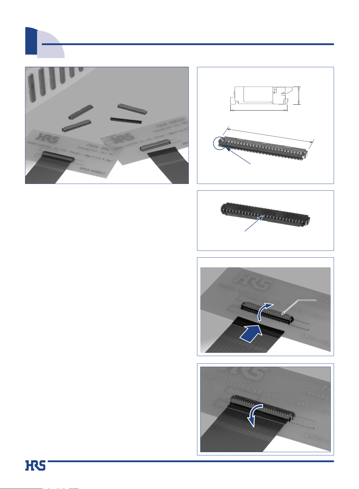
■Features
1.
Extremely light weight
The typical version, with all 51 contacts loaded, weights
only 0.1 grams.
2. Easy solderability on the PC board
The soldering leads are on 0.6 mm pitch, exiting on front
and back of the connector.
3.
Conductive traces on the PCB can run under
the connector
No exposed contacts on the bottom of the connector.
4. Easy FPC insertion and reliable electrical
connection
Proven Flip LockR actuator allows easy insertion of FPC.
Tactile sensation when fully closed confirms complete
electrical and mechanical connection.
5. Accepts standard thickness FPC
0.2mm thick standard Flexible Printed Circuit board can
be used.
This is the only ultra-low profile ZIF connector allowing
the use of standard FPC.
6. Board placement with automatic equipment
Flat top surface and packaging on the tape-and-reel
allows use of vacuum nozzles.
Standard reel contains 5,000 connectors.
■Applications
Mobile phones, PDA's, digital cameras, digital video
cameras, LCD connections, plasma displays (PDP), camera
modules and other compact devices requiring Flexible
Printed Circuit connections using high reliability ultra-small
profile connectors.
●
Space saving(51 pos. shown)
●
Can be mounted over conductive traces.
Metal fittings do no protrude
outside of the connector body
No exposed contacts on the bottom
of the connector
1.0mm
3.2mm
Actuator
●
Operation
(3) Close the actuator
(4) FPC connected
(3) Close the actuator
(4) FPC connected
(3) Close the actuator
(4) FPC connected
(3) Close the actuator
(4) FPC connected
(3) Close the actuator
(4) FPC connected
(3) Close the actuator
(4) FPC connected
(3) Close the actuator
(4) FPC connected
(3) Close the actuator
(4) FPC connected
(3) Close the actuator
(4) FPC connected
(3) Close the actuator
(4) FPC connected
(3) Close the actuator
(4) FPC connected
(3) Close the actuator
(4) FPC connected
(3) Close the actuator
(4) FPC connected
(3) Close the actuator
(4) FPC connected
(3) Close the actuator
(4) FPC connected
(3) Close the actuator
(4) FPC connected
(3) Close the actuator
(4) FPC connected
(1) Actuator open
(2) Insert FPC
(1) Actuator open
(2) Insert FPC
(1) Actuator open
(2) Insert FPC
(1) Actuator open
(2) Insert FPC
(1) Actuator open
(2) Insert FPC
(1) Actuator open
(2) Insert FPC
(1) Actuator open
(2) Insert FPC
(1) Actuator open
(2) Insert FPC
(1) Actuator open
(2) Insert FPC
(1) Actuator open
(2) Insert FPC
(1) Actuator open
(2) Insert FPC
(1) Actuator open
(2) Insert FPC
(1) Actuator open
(2) Insert FPC
(1) Actuator open
(2) Insert FPC
(1) Actuator open
(2) Insert FPC
(1) Actuator open
(2) Insert FPC
(1) Actuator open
(2) Insert FPC
q
w
r
e
0.3mm Contact Pitch, 1mm above the board, Flexible Printed Circuit ZIF Connectors
FH26 Series
The product information in this catalog is for reference only. Please request the Engineering Drawing for the most current and accurate design information.
All non-RoHS products have been discontinued, or will be discontinued soon. Please check the products status on the Hirose website RoHS search at www.hirose-connectors.com, or contact your Hirose sales representative.
16.8mm
FPC
FPC
Actuator
Actuator

69
Terminal type: SHW(SMT horizontal mounting)
Plating specifications
Blank: Tin-lead plated
(05) : Gold flash plated
---------------
---------------
Temperature: -55 ç/+15ç to +35ç/+85ç/+15ç to +35ç
Time: 30 / 2 to 3 / 30 / 2 to 3 (Minutes)
5 cycles
Reflow: At the recommended temperature profile
Manual soldering: 350ç +/-10ç for 5±1 seconds
1 mA
10 cycles
50 M ohms min.
No flashover or insulation breakdown.
100 V DC
90 V AC /one minute
100 m ohms max.
* Including FPC conductor resistance
Contact resistance: 100 m ohms max.
No damage, cracks, or parts dislocation.
No electrical discontinuity of 1
µs or more.
Contact resistance: 100 m ohms max.
No damage, cracks, or parts dislocation.
Frequency: 10 to 55 Hz, single amplitude of 0.75 mm, 10 cycles, 3
directions.
No electrical discontinuity of 1µs. min.
Contact resistance: 100 m ohms max.
No damage, cracks, or parts dislocation.
Acceleration of 981 m/s
2
, 6 ms duration, sine half-wave waveform,
3 cycles in each of the 3 axis
Contact resistance: 100 m ohms max.
Insulation resistance: 50 M ohms min.
No affect on appearance or performance.
96 hours at temperature of 40±2ç and humidity of 90% to 95%.
Contact resistance: 100 m ohms max.
Insulation resistance: 50 M ohms min.
No damage, cracks, or parts looseness.
No deformation of components affecting performance.
■Materials
■Ordering information
FH26 - 51S - 0.3 SHW (05)
1 3 42 5
Series name: FH26
No. of contacts: 13, 21, 23, 25, 27, 33, 35, 39,
41, 45, 51, 57, 71
Contact pitch: 0.3mm
1
2
3
4
5
Part
Contacts
Metal fitting
Insulator
Actuator
Poliamide, LCP
PA
Phosphor bronze
Color: Black
Color: Dark brown
Tin-lead plated (Note 3)
Tin plated (Lead free)
UL94V-0
Material Finish Remarks
■Specifications
Rating
Current rating 0.2A DC
Voltage rating 30V AC
Operating temperature range
-55 çto +85ç(Note 1)
Operating humidity range Relative humidity 90%
max. (No condensation)
Storage temperature range -10
ç
to +50ç(Note 2)
Storage humidity range
Relative humidity 90% max.
Recommended FPC :
Thickness: = 0.2±0.03mm tin-lead plated (Note 3)
4. Durability
(Insertion/ withdrawal)
5. Vibration
6. Shock
7. Humidity
(Steady state)
8. Temperature cycle
9.
Resistance to soldering heat
3. Contact resistance
1.
Insulation resistance
2.
Withstanding voltage
Item Specification Conditions
Note 1: Includes temperature rise caused by current flow.
Note 2: The term "storage" refers to products stored for long period of time prior to mounting and use. Operating Temperature Range
and Humidity range covers non- conducting condition of installed connectors in storage, shipment or during transportation.
Note 3: When FPC is gold plated, the connector contacts must be also gold plated: Specify the (05) plating code.
The product information in this catalog is for reference only. Please request the Engineering Drawing for the most current and accurate design information.
All non-RoHS products have been discontinued, or will be discontinued soon. Please check the products status on the Hirose website RoHS search at www.hirose-connectors.com, or contact your Hirose sales representative.

70
■Connector Dimensions
Notes The coplanarity of each terminal lead within specified dimension is ±0.1mm.
Packaged on tape and reel only. Check packaging specification.
1
2
All dimensions: mm
Embossed tape reel packaging (5,000 pieces/reel).
Order by number of reels.
Part Number
FH26-13S-0.3SHW
FH26-21S-0.3SHW
FH26-23S-0.3SHW
FH26-25S-0.3SHW
FH26-27S-0.3SHW
FH26-33S-0.3SHW
FH26-35S-0.3SHW
FH26-39S-0.3SHW
FH26-41S-0.3SHW
FH26-45S-0.3SHW
FH26-51S-0.3SHW
FH26-57S-0.3SHW
FH26-71S-0.3SHW
CL580-0209-3
CL580-0207-8
CL580-0203-7
CL580-0208-0
CL580-0204-0
CL580-0210-2
CL580-0205-2
CL580-0201-1
CL580-0206-5
CL580-0211-5
CL580-0200-9
CL580-0212-8
CL580-0202-4
13
21
23
25
27
33
35
39
41
45
51
57
71
5.4
7.8
8.4
9.0
9.6
11.4
12.0
13.2
13.8
15.0
16.8
18.6
22.8
3.0
5.4
6.0
6.6
7.2
9.0
9.6
10.8
11.4
12.6
14.4
16.2
20.4
3.6
6.0
6.6
7.2
7.8
9.6
10.2
11.4
12.0
13.2
15.0
16.8
21.0
4.23
6.63
7.23
7.83
8.43
10.23
10.83
12.03
12.63
13.83
15.63
17.43
21.63
4.9
7.3
7.9
8.5
9.1
10.9
11.5
12.7
13.3
14.5
16.3
18.1
22.3
CL No. Number of Contacts A B C D E
The product information in this catalog is for reference only. Please request the Engineering Drawing for the most current and accurate design information.
All non-RoHS products have been discontinued, or will be discontinued soon. Please check the products status on the Hirose website RoHS search at www.hirose-connectors.com, or contact your Hirose sales representative.
0.3
0.6
A
B
(0.12)
(1.25)
3.2
0.6
Number of contacts indicator
(0.12)
C
(D: FPC insertion slot dimension)
E
(0.3)
0.5
0.1 0.1
1
0.3
3.2
11
71
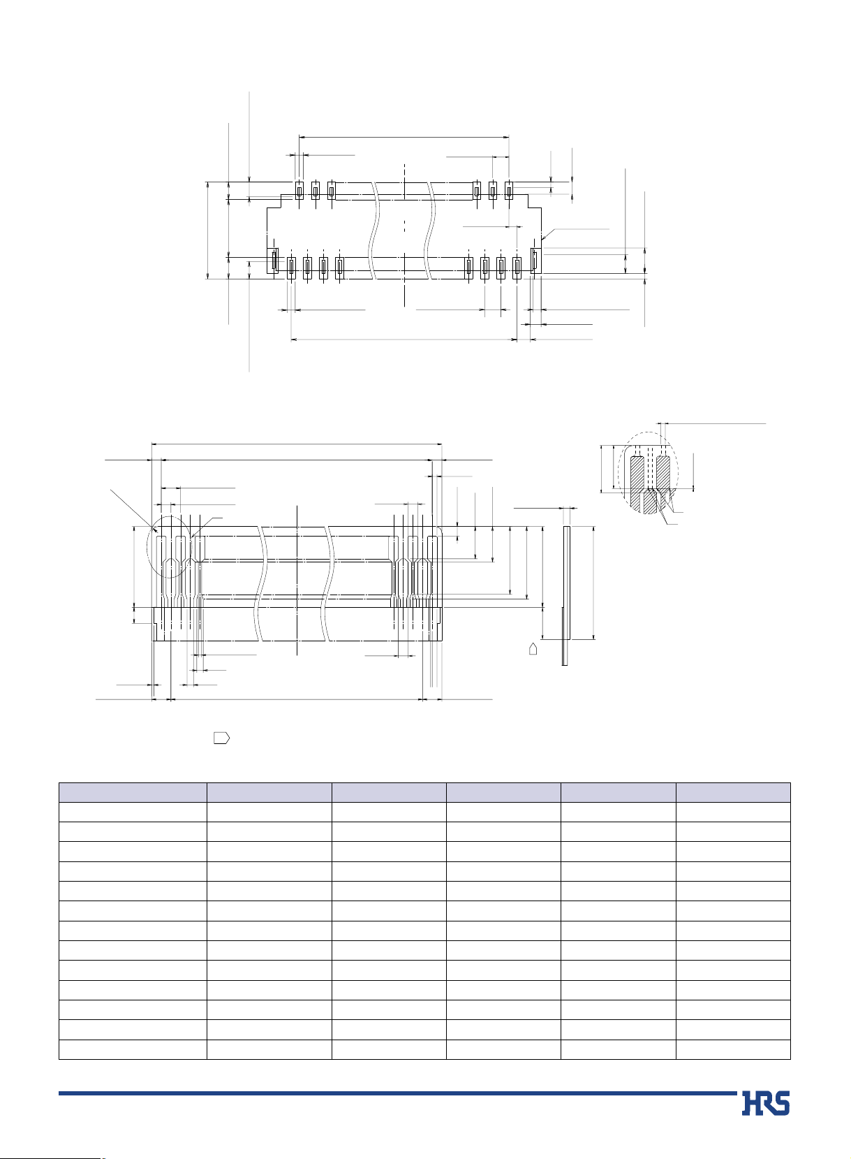
BRecommended PCB mounting pattern and metal mask dimensions
BRecommended FPC Dimensions
Detail H
Overlap between covering film layer and stiffener.
1
All dimensions: mm
Part Number
FH26-13S-0.3SHW
FH26-21S-0.3SHW
FH26-23S-0.3SHW
FH26-25S-0.3SHW
FH26-27S-0.3SHW
FH26-33S-0.3SHW
FH26-35S-0.3SHW
FH26-39S-0.3SHW
FH26-41S-0.3SHW
FH26-45S-0.3SHW
FH26-51S-0.3SHW
FH26-57S-0.3SHW
FH26-71S-0.3SHW
CL580-0209-3
CL580-0207-8
CL580-0203-7
CL580-0208-0
CL580-0204-0
CL580-0210-2
CL580-0205-2
CL580-0201-1
CL580-0206-5
CL580-0211-5
CL580-0200-9
CL580-0212-8
CL580-0202-4
13
21
23
25
27
33
35
39
41
45
51
57
71
3.0
5.4
6.0
6.6
7.2
9.0
9.6
10.8
11.4
12.6
14.4
16.2
20.4
3.6
6.0
6.6
7.2
7.8
9.6
10.2
11.4
12.0
13.2
15.0
16.8
21.0
4.2
6.6
7.2
7.8
8.4
10.2
10.8
12.0
12.6
13.8
15.6
17.4
21.6
CL No. Number of Contacts B C F
The product information in this catalog is for reference only. Please request the Engineering Drawing for the most current and accurate design information.
All non-RoHS products have been discontinued, or will be discontinued soon. Please check the products status on the Hirose website RoHS search at www.hirose-connectors.com, or contact your Hirose sales representative.
B±0.05
0.65±0.05
(0.55:Metal mask)(0.65:Metal mask)
0.3±0.03
(0.23:Metal mask)
0.6±0.05
(0.2)
(0.45)
(3.6)
2.15±0.05
0.3±0.05
0.8±0.05
(0.23:Metal mask)
F±0.05
0.3±0.07
R0.2 MAX
(2.5)
0.6±0.02
0.3±0.02
H
C±0.03
C±0.05
+0.04
0.3
-0.03
0.6±0.05
0.3±0.05
0.3±0.07
(0.15)
0.3±0.1
1±0.1
1.1±0.1
0.2±0.03
2.1±0.1
2.25±0.1
Outline of
the connector
(0.3:Metal mask)
0.4±0.05
0.5±0.05
2.5±0.3
(0.7:Metal mask)
1±0.1
1.1±0.1
0.95±0.05
0.2±0.05
(Lead plated 0.1 MAX)
0±0.03
B
A
πRELATIVE
POSITIONS
OF POINT-A dnd B
(0.5)
+0.04
0.3
0.1±0.02
(0.2)
(0.2)(0.07)
B±0.03
-0.03
3.5 MIN.(Stiffener)
0.5min.
1
0.6±0.070.6±0.07
 Loading...