

HRS FH19C, FH19SC Service Manual
1
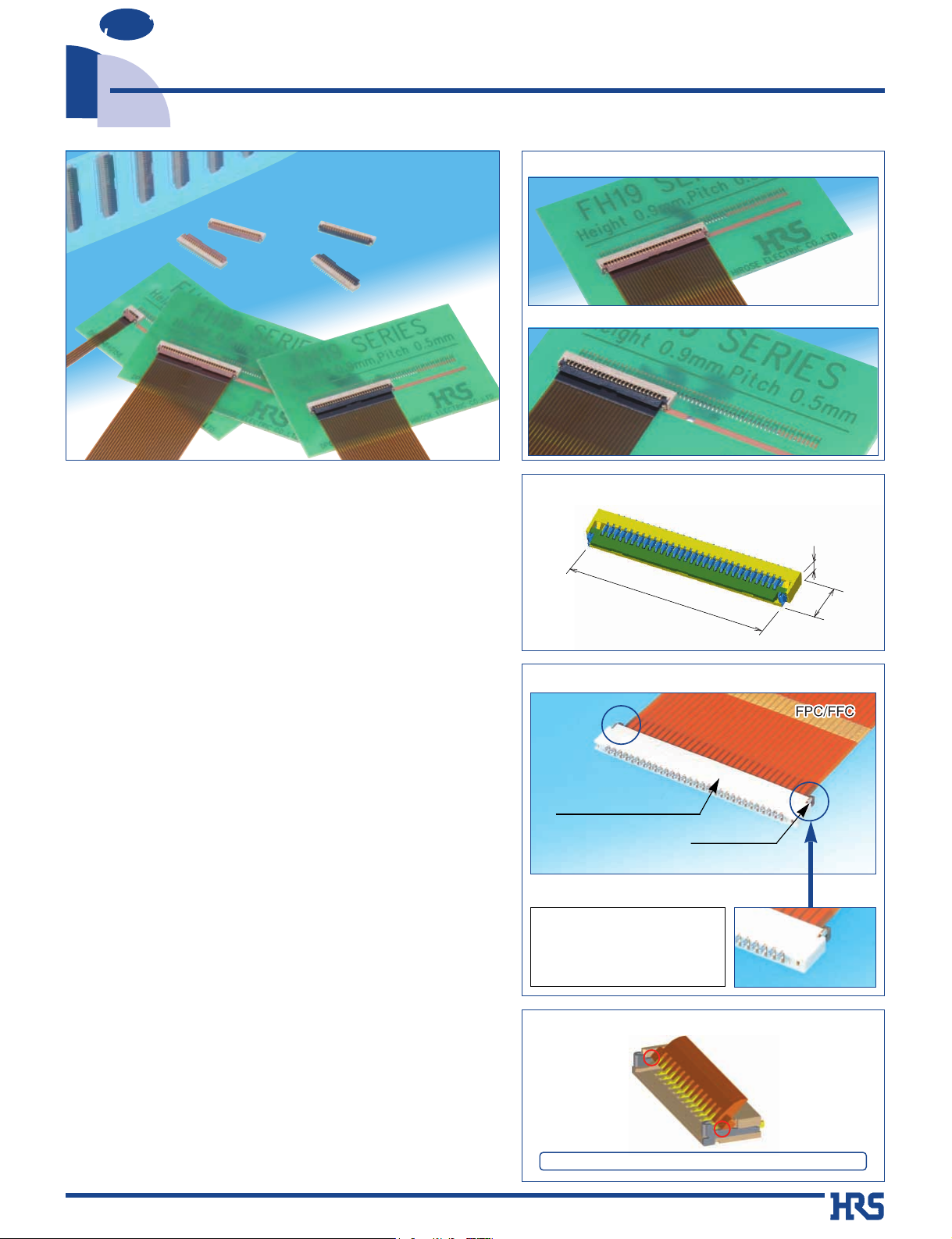
0.5mm pitch, 0.9mm above the board,
Flexible Printed Circuit & Flexible Flat Cable ZIF Connectors
FH19C & FH19SC Series
1.
Low-profile 0.5mm pitch FPC/FFC Connectors
Miniaturization of portable equipment and personal mobile
devices has created increased demand for a low profile,
high density, and high reliability connectors.
*The design of this connector has been made thinner and
smaller, with a height of 0.9mm and width of 3mm.
*PCB footprint: Reduced approximately 48% (as compared with
Hirose Electric's 0.5mm pitch FH12 Series connectors)
*Connector weight: Reduced approximately 78% (as compared
with Hirose Electric's 0.5mm pitch FH12 Series connectors)
2. Conductive traces on the PCB can run under
the connector
All bottom surface of the connector is solid, without any
exposure of the contact.
3. Proven Flip-Lock Actuator System assures
easy and reliable operation
Rotating actuator permits easy insertion and reliable
connection with the FPC & FFC.
Tactile sensation confirms complete mechanical locking of
the actuator and the electrical connection.
4. Accepts 0.2mm & 0.3mm thick FPC/FFC
No exposed contacts on the bottom of the connector.
The connector will also terminate with 0.2mm thick Flat
Flexible Cable (FFC).
5. Board placement with automatic equipment
Flat top surface and packaged on the tape-and-reel allows
use of vacuum nozzles.
Standard reel contains 5,000 pieces.
■Applications
Notebook PC’s, PDA’s, digital cameras and other compact
devices requiring interconnections of the main circuit board
with the LCD, plasma display (PDP), HDD or other compact
devices requiring FPC/FFC connections using low profile,
high reliability ZIF connectors.
0.9mm
3mm
17mm
● Can be mounted over conductive traces
●
0.9mm high
● Metal Fittings (Leadless Type)
No protrusions on the sides
allows close side-by-side
board placement.
Metal fittings
(Leadless)
Enclosed construction
(No exposed contacts)
FH19C – FPC/FFC thickness: 0.2±0.03mm
Actuator color: Brown
Actuator color: Black
FH19SC – FPC/FFC thickness: 0.3±0.03mm
NEW
2006.9
● Actuator Temporary Hold Mechanism
Actuator stays open during insertion of the FPC/FFC.
■Features
The product information in this catalog is for reference only. Please request the Engineering Drawing for the most current and accurate design information.
All non-RoHS products have been discontinued, or will be discontinued soon. Please check the products status on the Hirose website RoHS search at www.hirose-connectors.com, or contact your Hirose sales representative.
2
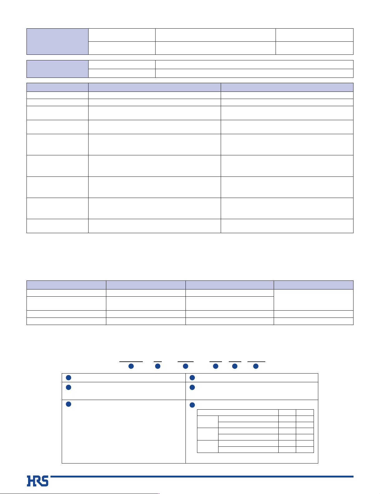
FH19 C - 30S - 0.5 SH (05)
1 2 4 53
6
■Product Specifications
Rating
Current rating 0.5 A DC
Voltage rating 50 V AC
Operating temperature range
-55çto +85ç(Note 2)
Operating humidity range
Relative humidity 90% max. (No condensation)
Storage temperature range
-10çto +50ç(Note 3)
Storage humidity range
Relative humidity 90% max.
■Materials
Note 1: When passing the current through all of the contacts, use 70% of the current rating.
Note 2: Includes temperature rise caused by current flow.
Note 3: The term “storage” refers to products stored for long period of time prior to mounting and use. Operating Temperature Range and
Humidity range covers non- conducting condition of installed connectors in storage, shipment or during transportation.
Note 4: When FPC is gold plated, the connector contacts must be also gold plated: Select the (05) code.
Item Specification Conditions
1. Insulation resistance 500 M ohms min. 100 V DC
2. Withstanding voltage No flashover or insulation breakdown 150 V AC/1 minute
3. Contact resistance
100 m ohms max.
1 mA
*Including FPC/FFC conductor resistance
4. Durability Contact resistance: 100 m ohms max.
20 cycles
(insertion/ withdrawal)
No damage, cracks, or parts dislocation.
No electrical discontinuity of 1
µs or more.
5. Vibration Contact resistance: 100 m ohms max.
No damage, cracks, or parts dislocation.
No electrical discontinuity of 1
µs. min.
6. Shock Contact resistance: 100 m ohms max.
No damage, cracks, or parts dislocation.
7. Humidity
Contact resistance: 100 m ohms max.
(Steady state)
Insulation resistance: 100 M ohms min.
No damage, cracks, or parts dislocation.
Contact resistance: 100 m ohms max.
8. Temperature cycle Insulation resistance: 100 M ohms min.
No damage, cracks, or parts dislocation.
9. Resistance to
No deformation of components affecting performance.
Reflow: At the recommended temperature profile
soldering heat Manual soldering: 350ç±5ç for 5 seconds
96 hours at temperature of 40ç and humidity of
90 to 95%
Temperature: -55ç
/
+
15ç to +35ç
/
+
85ç
/
+
15ç to +35ç
Time
: -30
/
2 to 3
/
+
30/2 to 3(Minutes)
5 cycles
Acceleration of 981 m/s2, 6 ms duration, sine halfwave waveform, 3 cycles in each of the 3 axis.
Frequency: 10 to 55 Hz, single amplitude of
0.75mm, 10 cycles in each of the 3 directions
■Ordering information
Series name : FH19
C : FPC/FFC thickness : 0.2mm
SC : FPC/FFC thickness : 0.3mm
No. of contacts : 4 to 50
Contact pitch : 0.5mm
Terminal type
SH: SMT horizontal mounting type
Material and plating specifications :
1 4
2 5
3
6
Recommended
FPC, FFC
FH19C Series
FH19SC Series
Thickness: = 0.2 ± 0.03mm Gold or tin-lead plated (Note 3)
Thickness: = 0.3 ± 0.03mm Gold or tin-lead plated (Note 3)
Insulator LCP Color: Beige
Actuator PPS/LCP
UL94V-0
Contacts Phosphor bronze
Gold flash or Tin-lead plated (Note 4)
-------
Metal fittings Phosphor bronze Pure tin reflow plated
-------
Part Material Finish Remarks
Color: Brown (FH19C Series)
Color: Black (FH19SC Series)
Actuator material PPS
------
-----(05)
(51)
------
------
LCP
(05)
(51)
------
-----(05)
(51)
FH19C
FH19SC
4 to 10 pos.
FH19SC
11 to 50 pos.
Contact: Gold flash plated
Contact: Tin-lead plated
Contact: Gold flash plated
Contact: Tin-lead plated
Contact: Gold flash plated
Contact: Tin-lead plated
The product information in this catalog is for reference only. Please request the Engineering Drawing for the most current and accurate design information.
All non-RoHS products have been discontinued, or will be discontinued soon. Please check the products status on the Hirose website RoHS search at www.hirose-connectors.com, or contact your Hirose sales representative.
3
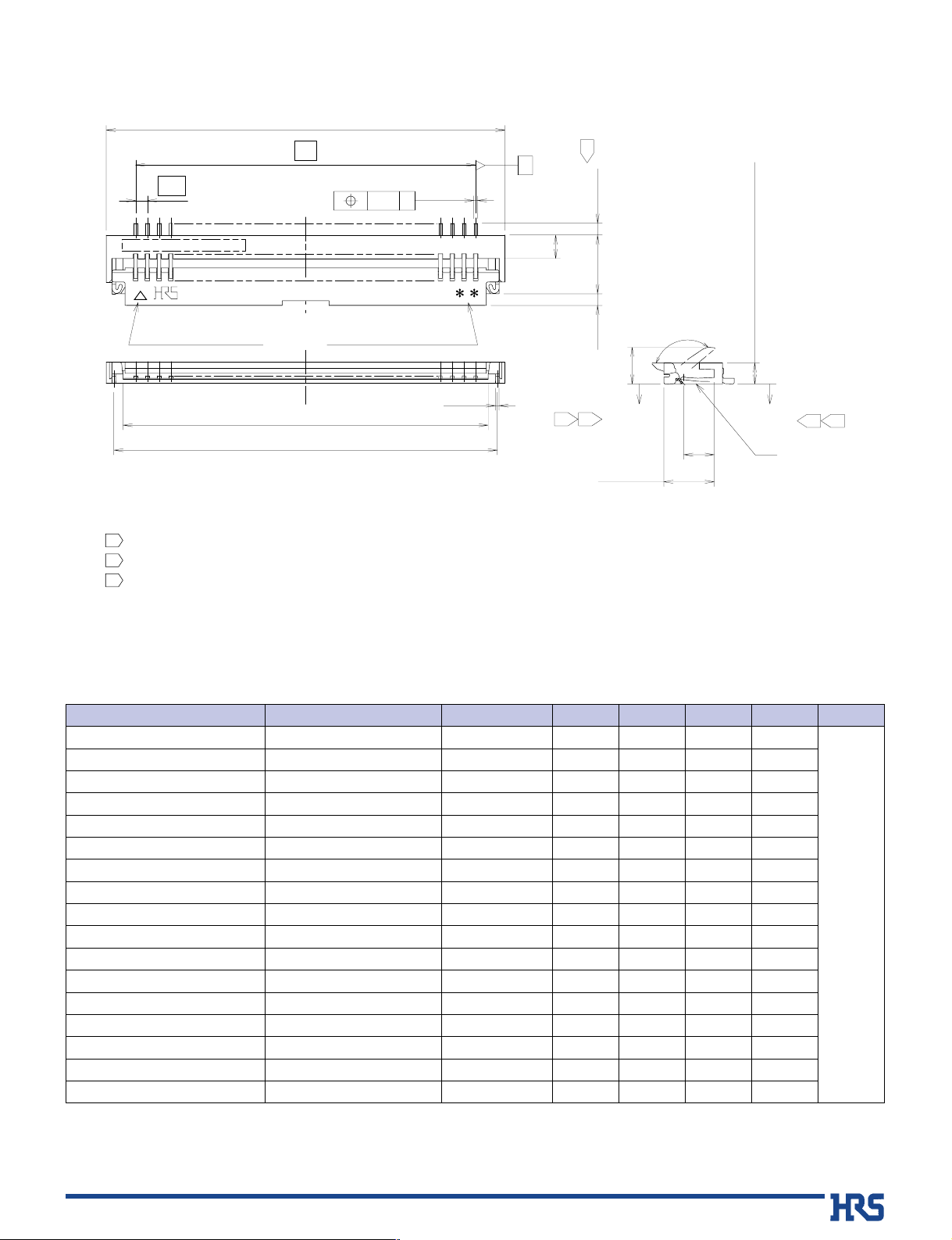
■Connector Dimension
[
FH19C Series
]
Notes The coplanarity of each terminal lead and metal fitting is within 0.1
The contact terminal lead position indicates the dimension from the bottom surface of the insulator body.
Difference between terminal contact to be max. 0.1mm.
Any discoloration of the plastic compound will NOT AFFECT form, fit or function of the connector.
Note that preventive hole for sink mark could be added for improvement.
1
2
3
4
D±0.1
A
(1)
2.5±0.15(0.5)
0.5
B
A±0.15
(C: FPC insertion slot dimension)
(0.15)
(0.15)
0.5
+0.15
0
(1.6)
0.9±0.1(Including contact terminal leads)
(1.3)
(130°)
2.15±0.2
0.15MAX
0.15MAX
1
12
2
3
S
0.15
G
Polarizing mark indicator
Number of contacts indicator
G
∞Number of contacts
Unit: mm
Note1: Embossed tape reel packaging (5,000 pieces/reel).
Order by number of reels.
Note2: When selecting the RoHScompliant code (05) as gold plated contacts.
Code (51) is not RoHS compliant.
Part Number
FH19C-04S-0.5SH(**)
FH19C-06S-0.5SH(**)
FH19C-07S-0.5SH(**)
FH19C-08S-0.5SH(**)
FH19C-09S-0.5SH(**)
FH19C-10S-0.5SH(**)
FH19C-12S-0.5SH(**)
FH19C-13S-0.5SH(**)
FH19C-15S-0.5SH(**)
FH19C-17S-0.5SH(**)
FH19C-20S-0.5SH(**)
FH19C-21S-0.5SH(**)
FH19C-24S-0.5SH(**)
FH19C-27S-0.5SH(**)
FH19C-30S-0.5SH(**)
FH19C-40S-0.5SH(**)
FH19C-50S-0.5SH(**)
CL No.
CL580-0410-1-**
CL580-0409-2-**
CL580-0411-4-**
CL580-0404-9-**
CL580-0403-6-**
CL580-0412-7-**
CL580-0413-0-**
CL580-0405-1-**
CL580-0406-4-**
CL580-0408-0-**
CL580-0402-3-**
CL580-0414-2-**
CL580-0407-7-**
CL580-0401-0-**
CL580-0400-8-**
CL580-0416-8-**
CL580-0417-0-**
Number of Contacts
4
6
7
8
9
10
12
13
15
17
20
21
24
27
30
40
50
A
04.0
05.0
05.5
06.0
06.5
07.0
08.0
08.5
09.5
10.5
12.0
12.5
14.0
15.5
17.0
22.0
27.0
B
01.5
02.5
03.0
03.5
04.0
04.5
05.5
06.0
07.0
08.0
09.5
10.0
11.5
13.0
14.5
19.5
24.5
C
02.57
03.57
04.07
04.57
05.07
05.57
06.57
07.07
08.07
09.07
10.57
11.07
12.57
14.07
15.57
20.57
25.57
D
03.35
04.35
04.85
05.35
05.85
06.35
07.35
07.82
08.85
09.85
11.35
11.85
13.35
14.85
16.35
21.35
26.35
RoHS
YES
(Note2)
The product information in this catalog is for reference only. Please request the Engineering Drawing for the most current and accurate design information.
All non-RoHS products have been discontinued, or will be discontinued soon. Please check the products status on the Hirose website RoHS search at www.hirose-connectors.com, or contact your Hirose sales representative.
 Loading...