

HRS FH17 Service Manual
25
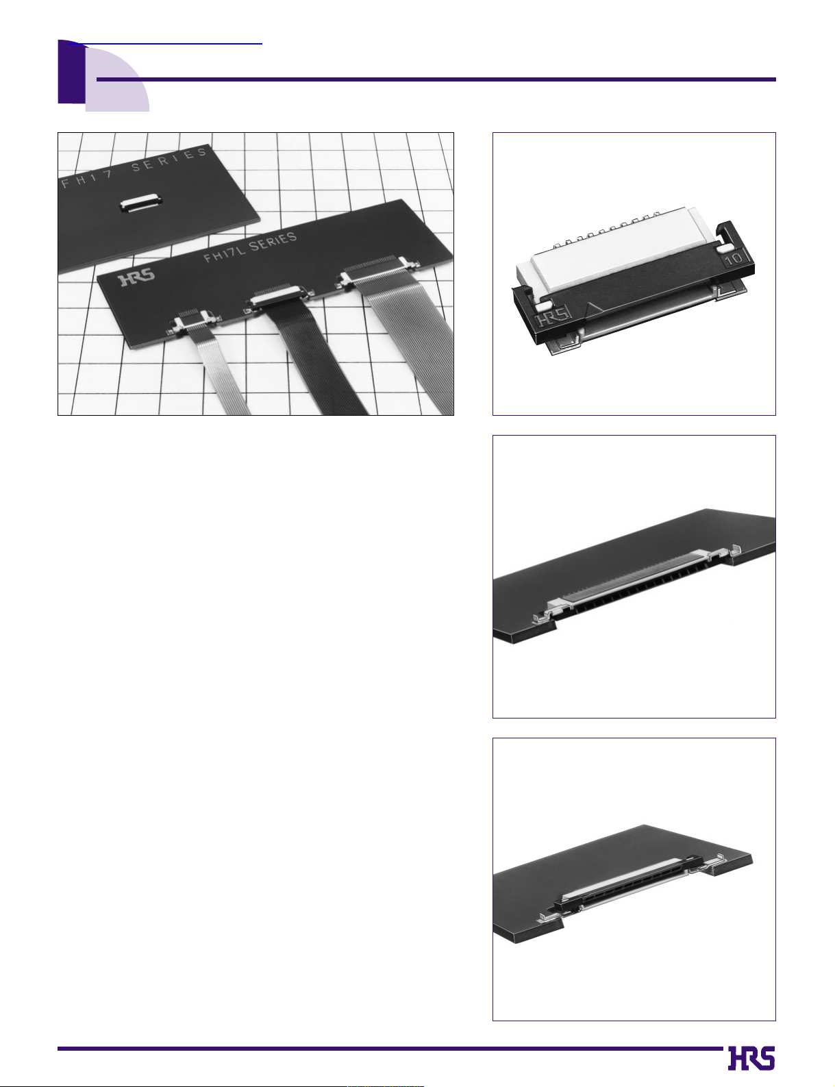
Low Profile 0.5mm Pitch Connectors For FPC
FH17 Series
■Features
1. Low profile 0.5mm pitch FPC connectors
As products become lighter/thinner/shorter/smaller, requests for
thinly-made type FPC connectors are rapidly increasing. The FH17
Series is an ultra miniature version of the Hirose’s popular FH12
Series. FH17 has 35
%
-
45
% lower profile above the board.
*
FH17 : On-board type, height of 1.3 mm from board surface
*
FH17L: Offset standard type, height of 1.0 mm from board surface
*
FH17LR: Offset reverse type, height of 1.0 mm from board surface
2. Easy to use Flip-Lock Actuator
Flip-lock (rotating type) ZIF mechanism enables good connectivity
of FPC by a simple operation and light force. No board space is
required for flip lock operation as compared to slide lock ZIF
connectors.
3. Variety of Sizes and Options
In addition to the on-board type (FH17), board drop-in types (FH17L
and FH17LR) are also available. Selection will depend on the
application mounting. Connectors are available with 8 to 30
contacts.
4. Adaptable to thin-type FPC
It conforms to the thin-type FPC (0.17mm)now being used for small
size electronic equipment such as cameras, etc.
(Thin-type FPC: Specifications without stiffener of double-faced
FPC will reduce the cost of FPC. A single-faced FPC still requires
stiffener, but the reduced thickness is easier for manufacturers to
produce.
5. Packaged for Pick-and-Place machine
Embossed tape packaging allows automatic mounting.
■Applications
Mobile telephones, devices using LCDs, CD-ROMs, cameras, other
miniature devices
FH17L(board drop-in standard type)flip-lock mechanism
FH17LR (board drop-in reverse type) flip-lock mechanism
FH17 (on-board type) flip-lock mechanism
(
查询FH17-10S-0.5SH供应商查询FH17-10S-0.5SH供应商
26
■Product Specifications
100V DC
150V AC/1 minute
20 cycles
1mA
Frequency: 10 to 55 Hz, single amplitude of 0.75 mm,
2 hours in each of the 3 directions.
Acceleration of 490 m/s
2
, 11 ms duration,
sine half-wave waveform, 3 cycles in each of the 3 axis.
96 hours at temperature of 40ç and humidity of 90% to 95%
5 cycles under conditions as follows; Temperature:
-40ç / 15 to 35ç / 85ç / 15 to 35ç,
Time: 30 / 5 max. / 30 / 5 max.(minutes)
Reflow: At the recommended temperature profile
Manual soldering: 350±5ç for 3 seconds
Applicable FPC
t=0.17 Tin-lead plating
+0.03
-0.04
Item
1.
Insulation resistance
2.
Withstanding voltage
4.Durability
(Insertion/withdrawal)
3.Contact resistance
5.Vibration
6.Shock
7.Humidity
(Steady state)
8.
Temperature cycle
9.Resistance to
soldering heat
Specification
500M ohms minimum
No flashover or insulation breakdown.
50m ohms maximum
Contact resistance : 50m ohms maximum
No damage, cracks, or parts dislocation.
No electrical discontinuity of 1µs or more
Contact resistance: 50m ohms maximum.
No damage, cracks, or parts dislocation.
No electrical discontinuity of 1µs or more
Contact resistance: 50m ohms maximum
No damage, cracks, or parts dislocation.
Contact resistance: 50m ohms maximum
Insulation resistance: 50M ohms minimum
No damage, cracks, or parts dislocation.
Contact resistance: 50m ohms maximum
Insulation resistance: 50M ohms minimum
No damage, cracks, or parts dislocation.
No deformation of components affecting performance.
Conditions
(Note:4)
FH17L - 30S - 0.5 SH (05
)
1 2 3 4 5 6
■Ordering Information
Remarks
--------------
--------------
UL94V-0
UL94V-0
■Material
Part
Contact
Metal fittings
Insulated tape
Insulator
Insulator
Material
LCP
PPS
Phosphor bronze
Brass
Polyamide
Finish
--------------
-------------Tin-lead plating
Tin-lead plating
--------------
2
3
4
5
6
1
Ratings
Current rating
Voltage rating
0.4A DC
50V AC
Operating temp. range
Operatinghumidity range
-40 to +70ç(Note.1)
relative humidity 90% max.
(No dew-fall)
Storage temp. range
Storage Humidity range
-10 to +50ç(Note.2)
relative humidity 90% max.
(No dew-fall)
Note 1: Includes temperature rise caused by current flow.
Note 2: The term "storage" refers to products stored for long period of time prior to mounting and use. Operating Temperature Range and
Humidity range covers nonconducting condition of installed connectors in storage, shipment or during transportation.
Note 3. The above standards represent this series. The individual formal agreement should be based on the Specification.
Series Name FH17
Mounting Type None : On-Board type
L : Offset type
LR : Offset reverse type
Number of Contacts 8, 10, 15, 20, 24, 30
Contacts Pitch 0.5mm
Contact Style
SH : SMT horizontal mounting type
Plating specifications Blank : Tin-lead plating
(05)
: Gold plating
27
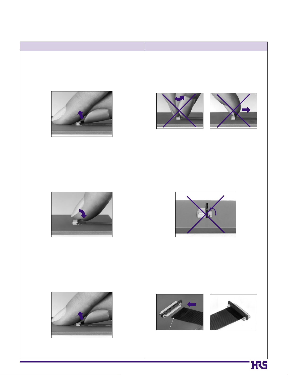
BConnector Operating Instructions, precautions and recommendations
Operation Precautions
1.FPC Termination procedure. Connector
installed on the board.
1) Lift up the actuator. Use thumb or index finger.
2) Rotate down the actuator until firmly closed.
It is critical that the inserted FPC is not moved and
remains fully inserted. Should the FPC be moved,
open the actuator and repeat the process, starting
with Step 1 above.
2) The connector will assure reliable performance
when the actuator is open to 90° maximum (see
fig.1) Do not exceed this angle, as this may cause
permanent damage to the connector.
2.FPC Removal
1) Lift up the actuator.
2) Carefully remove the FPC.
3) Assure that the FPC is fully inserted parallel to
mounting surface, with the exposed conductive
traces facing down.
FPC conductor surface
(Bottom side)
1) Do not apply excessive force or use any type of
tool to operate the actuator.
28
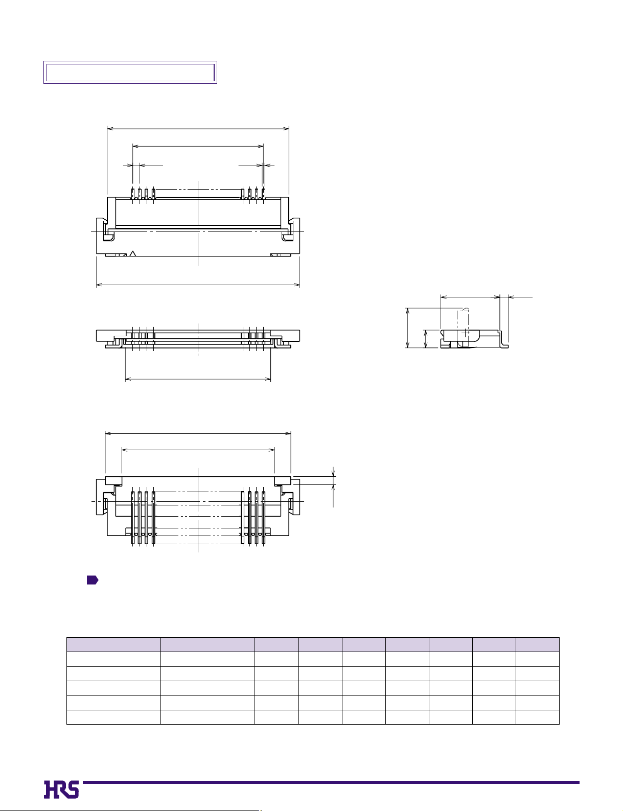
Note The coplanarity of each lead and metal fitting is within 0.1.
On-Board Type (FH17
)
(mm)
Note:Embossed tape reel packaging(2,000 pieces/reel).
Order by number of reels.
Part Number
FH17-10S-0.5SH
FH17-15S-0.5SH
FH17-20S-0.5SH
FH17-24S-0.5SH
FH17-30S-0.5SH
586-0638-8
586-0657-2
586-0637-5
586-0645-3
586-0625-6
10
15
20
24
30
08.2
10.7
13.2
15.2
18.2
04.5
07.0
09.5
11.5
14.5
09.8
12.3
14.8
16.8
19.8
05.57
08.07
10.57
12.57
15.57
08.5
11.0
13.5
15.5
18.5
06.1
08.6
11.1
13.1
16.1
CL No.
Number of
Contacts
A B C D E F
1
A
B
0.5
0.2
C
4.3
2.9
1.3
D
E
F
0.6
0.6
 Loading...