

HRS DF7 Service Manual
1
3.96 mm Pitch Miniature Connectors for Internal Power Supplies (UL,C-UL and TÜV Listed)
DF7 Series
2004.7
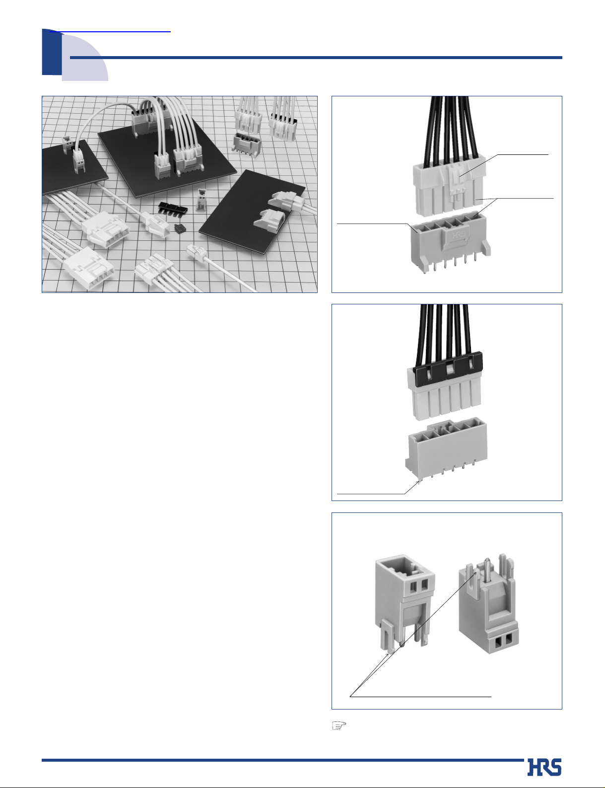
■Features
1. Complete Locking Function
Reliable interior lock protects mated connectors from
accidental disconnection.
2. Increased Contact Retention of Crimped
Contacts and Prevention of Incomplete
Insertion
Separate contact retainer increases the contact
retention, assures and visually confirms the complete
contact insertion.
3. Molded-in Contact Retention Tabs
Handling of terminated contacts during the assembly and
termination is easier and avoids entangling of wires,
since there are no protruding metal tabs.
4. Incorrect Insertion Prevention
Connectors are polarized to assure correct mating with
corresponding parts.
5.Solder Crack Prevention
Glass reinforced resin is used in the pin header bodies to
prevent solder cracks caused by the heat shrinkage.
6. Prevention of Incorrect Board Placement
Built-in locating posts assure correct connector
placement and orientation on the board.(2-12 pos.)
7. Supports Sealing after Installation.
Sealing compound can be applied to the board installed
connector for distance of 6 mm max. from the mounting
surface (9 mm max. for single position).
8.Cost Effective Tooling
The same crimping tools are used to terminate socket
and pin contacts.
9. Prevention of Short Circuits between
Adjacent Contacts
Each contact is completely surrounded by the insulator
housing, electrically isolating it from adjacent contacts.
Completely
enclosed
locking system
Complete
Locking
Function
Board Eyelet mounting
One pos. type can also be mounted
to boards that have eyelets.
Continued.
Guide post
Prevention of
Incorrect Connections
Full barrier
between adjacent
contacts.
查询DF7-1618PC供应商
2
■Ordering information
DF7 -
**
Series name: DF7, DF7A, DF7E
Number of contacts: 1 to 5
Connector type
S: Socket
DS: Double-row socket
P: Header
DP: Double-row Header
EP: In-line plug
RS/P: Retainer
Contact pitch: 3.96mm(7.92 mm)
Type of housing: header
C: Crimp housing
DSA: Straight header
DS: Right-angle header
Blank: Retainer
1
2
3
4
5
Applicable Conductor
1618: AWG 16 to AWG 18
2022: AWG 20 to AWG 22
2426: AWG 24 to AWG 26
Packaging
SCF: Socket contacts / Reel
SC: Socket contacts / Bag
PCF: Plug contacts / Reel
PC: Plug contacts / Bag
6
7
1 6
SCF
7
DF7 -
*
S-3.96 C
1 2 3 4 5
10. 10 A maximum Current
Connector can carry current of 10 A per contact with
#16 AWG conductor.Refer to page 3 for current
ratings for multi-position connectors using other
conductor sizes.
11. Color Variations
1 pos. is available in a standard 3 colors: natural,
blue, and red.
12. Supports Eyelets
1 pos. can be mounted to boards which have eyelets
attached.
■Applications
Office equipment, power supplies for industrial, medical
and instrumentation applications, variety of consumer
electronic and electrical applications.
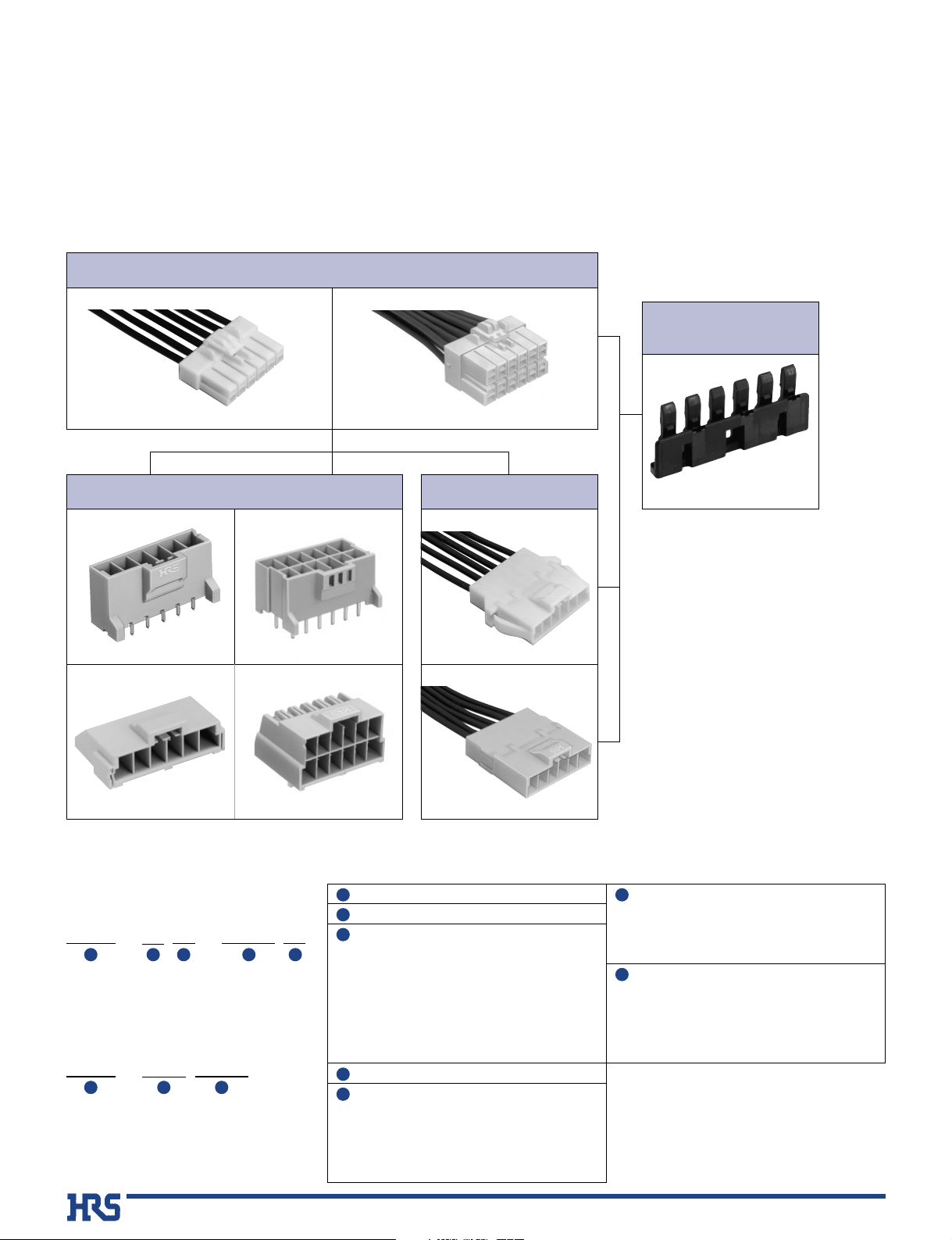
Crimp Sockets
Header
Refer to page 4 for details.
●
Single row, straight type
●
Single row, right angle type
Refer to page 5 for details.
Refer to page 11 for details.
●
Double rows, straight type
●
Double row, right angle type
Refer to page 11 for details.
In-line plug
●Panel lock type
Shown with
terminated and installed contacts.
Refer to page 7 for details.
Shown with
terminated and installed contacts.
Refer to page 6 for details.
Retainer
(optional, order separately)
Refer to page 10 for details.
●Single row ●Double rows
Shown with terminated
and installed contacts.
Refer to page 8, 9 for details.
Shown with terminated
and installed contacts.
Refer to page 12 for details.
●
Socket, Header
●
Contacts
3
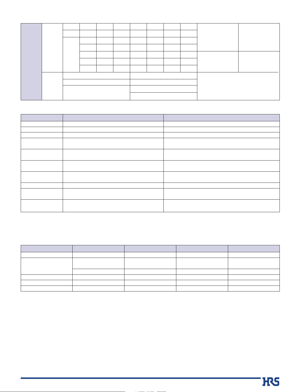
■Materials
Product
Sockets
Headers
In-line plug
Retainer
Crimp contacts
Part
Insulator
Insulator
Contact
Insulator
Insulator
Contacts
Material
Polyamide
Polyamide
(Glass reinforced)
High conductivity copper alloy
Polyamide
Polyamide
High conductivity copper alloy
Finish
Color: White
Color: Beige (Single row)
Color: Grey (Double row)
Tin-lead plating (Note)
Color: White
Color: Black
Tin plating (Note)
Remarks
UL94V-0
UL94V-0
---------------UL94V-0
UL94V-0
----------------
■Product Specifications
Ratings
Current
rating
Row
No. of contacts
AWG16 AWG18 AWG20 AWG22 AWG24 AWG26
1 2~10 10A 7A 5A 4A 4A 3A
4 10A 9A 7A 6A 4A 3A
6 9A8A6A5A4A3A
2 8 9A 8A 6A 5A 4A 3A
10 8A 7A 5A 4A 4A 3A
12 8A 7A 5A 4A 4A 3A
Operating temperature range
Operating humidity range
Storage temperature range
Storage humidity range
-10çto 60ç (Note 2)
40% to 70% (Note 2)
-35ç to 85ç (Note 1)
20% to 80%
Voltage
rating
Specificatoin
UL/C-UL
TÜV
AC630V
AC/DC 600V
AC/DC 600V(7.92mm pitch)
AC/DC 300V (3.96mm pitch)
UL/C-UL/TÜV
UL
C-UL
TÜV
File No.and Recognition No
:E52653
:E52653
:R9750437
10 m ohms max. 20mV max., 1mA
500 V DC
1500 V AC for 1 minute
Measured with a steel pin of 0.64 x 1.2 ± 0.002 mm
Contact resistance of 20 m ohms max.
Frequency 10 to 55 Hz, single amplitude of 0.75 mm, 3 axis, 2
hours
Acceleration of 490 m/s
2
, 11 ms duration, sine half-wave
waveform, 3 cycles in each of the 3 axis.
Temperature 40
ç ± 2ç, 90% to 95% RH, 96 hours
(-55ç: 30 minutes →5 to 35ç: 5 minutes →85ç: 30 minutes →5
to 35ç: 5 minutes) for 5 cycles
Flow solder temperature 250ç, 10 seconds
Manual soldering: Soldering iron temperature 300ç, 3 seconds
Contact resistance(Initial value)
1000 M ohms min.
No flashover or Insulator breakdown
0.3N min., 4.5N max.
30 cycles
No momentary disconnections of 1 µs min.
No electrical discontinuity of 1 µs. min.
Contact resistance 20 m ohms max.
Contact resistance of 20 m ohms max.
No deformation of the insulator parts affecting
performance
11. Contact resistance
12.
Insulator resistance
13.
Withstanding voltage
14.
Insertion-Extraction force
(per contact)
15. Durability
(mating/unmating)
16. Vibration
17. Shock
18. Humidity
19. Temperature cycle
10. Resistance to
soldering heat
Item Specification Condition
Note 1: Includes temperature rise caused by the current flow.
Note 2: The term “storage” refers to products stored for long period of time prior to mounting and use. Operating Temperature Range
and Humidity range covers non- conducting condition of installed connectors in storage, shipment or during transportation.
Note: Hirose Electric's plating incorporates anti-whisking compounds.
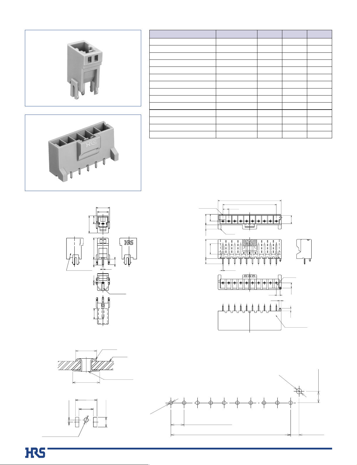
4
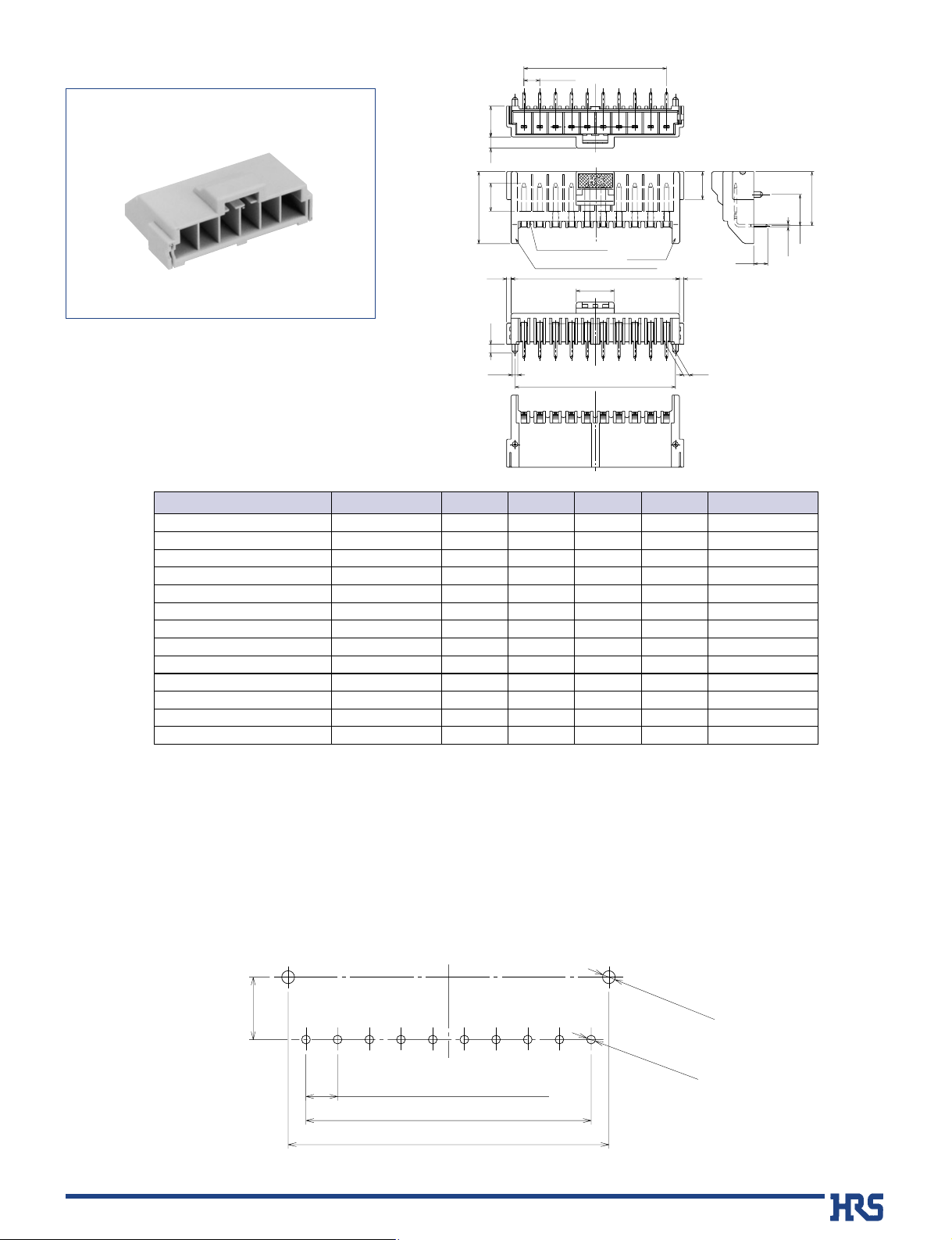
■ Straight header
B PCB mounting pattern (Board thickness: 1.6 ± 0.1)
Cavity No.
B
DF7
3.45
2.49
Ø1.4
1.7
12.9
3.5
7
M0.64
A
B
P=3.96
5.5
4.55
7.12.8
(Note2)
10
No. of contacts
indicator (Note3)
6L09
Production Lot No.
P=3.96±0.05(7.92±0.05)
3.45±0.05
2.49±0.05
B±0.1
Ø1.1
+0.1
0
Ø1.6
+0.1
0
0.64
7.8
6
6.44
9.9
12.23.5
3.2
0.84
Cavity No.
1
A
9E26
7.8
6
4.55
Production Lot No.
9E26
Board
Ø3.9 MAX
Ø5 MAX
0.8±0.1
5.4
+0.1
_0.3
8±0.1
3.6±0.1
Eyelet
Soldering side
Note 5: One pos. type can also be mounted to boards
that have installed eyelets.
Ø1.6
+0.15
_0.25
mm Without eyelet
for eyelet
1.4
+0.1
_ 0
1 Pos. 2 to 10 Pos.
1 Pos.
2 to 10 Pos.
1 Pos.
2 to 10 Pos.
CL No.
CL680-0133-1
CL680-0036-5
CL680-0037-8
CL680-0038-0
CL680-0039-3
CL680-0040-2
CL680-0041-5
CL680-0042-8
CL680-0043-0
CL680-0044-3
CL680-0108-4
CL680-0109-7
CL680-0110-6
CL680-0111-9
DF7- 1P-3.96DSA
DF7- 2P-3.96DSA
DF7- 3P-3.96DSA
DF7- 4P-3.96DSA
DF7- 5P-3.96DSA
DF7- 6P-3.96DSA
DF7- 7P-3.96DSA
DF7- 8P-3.96DSA
DF7- 9P-3.96DSA
DF7-10P-3.96DSA
DF7- 2P-7.92DSA
DF7- 3P-7.92DSA
DF7- 4P-7.92DSA
DF7- 5P-7.92DSA
1
2
3
4
5
6
7
8
9
10
2
3
4
5
-------------
10.40
14.36
18.32
22.28
26.24
30.20
34.16
38.12
42.08
14.36
22.28
30.20
38.12
-------------
3.96
7.92
11.88
15.84
19.80
23.76
27.72
31.68
35.64
7.92
15.84
23.76
31.68
Part Number
Number of contacts
A B
Note 1) Bag packaging (100 pieces/bag). Order by number of bags.
Note 2) The 2 pos. type does not have walls on both sides.
Note 3)
DF7-2P-7.92DSA plug has #2 contact positions of DF7-3P-3.96DSA without contacts inserted and the number of pos. indication is 2.
(Mating receptacle: DF7#-3S-3-96C)
DF7-3P-7.92DSA plug has #2 and #4 contact positions of DF7-5P-3.96DSA without contacts inserted and the number of pos. indication is 3.
(Mating receptacle: DF7#-5S-3-96C)
DF7-4P-7.92DSA plug has #2, #4 and #6 contact of DF7-7P-3.96DSA without contacts inserted and the number of pos. indication is 4.
(Mating receptacle: DF7#-7S-3-96C)
DF7-5P-7.92DSA plug has #2, #4, #6 and #8 contact positions of DF7-9P-3.96DSA without contacts inserted and the number of pos. indication is 5.
(Mating receptacle: DF7#-9S-3-96C)
5
Note 1) Tray packaging. Order by number of quantity in the tray.
Note 2)
DF7-2P-7.92DS plug has #2 contact positions of DF7-3P-3.96DS without contacts inserted and the number of pos. indication is 2.
(Mating receptacle: DF7#-3S-3-96C)
DF7-3P-7.92DS plug has #2 and #4 contact positions of DF7-5P-3.96DS without contacts inserted and the number of pos. indication is 3.
(Mating receptacle: DF7#-5S-3-96C)
DF7-4P-7.92DS plug has #2, #4 and #6 contact of DF7-7P-3.96DS without contacts inserted and the number of pos. indication is 4.
(Mating receptacle: DF7#-7S-3-96C)
DF7-5P-7.92DS plug has #2, #4, #6 and #8 contact positions of DF7-9P-3.96DS without contacts inserted and the number of pos. indication is 5.
(Mating receptacle: DF7#-9S-3-96C)
■ Right angle header
B PCB mounting pattern (Board thickness: 1.6 ± 0.1)
CL No.
CL680-0081-0-24
CL680-0082-2-24
CL680-0083-5-24
CL680-0084-8-24
CL680-0085-0-24
CL680-0086-3-24
CL680-0087-6-24
CL680-0088-9-24
CL680-0089-1-24
CL680-0124-0-24
CL680-0125-3-24
CL680-0126-6-24
CL680-0127-9-24
DF7- 2P-3.96DS(24)
DF7- 3P-3.96DS(24)
DF7- 4P-3.96DS(24)
DF7- 5P-3.96DS(24)
DF7- 6P-3.96DS(24)
DF7- 7P-3.96DS(24)
DF7- 8P-3.96DS(24)
DF7- 9P-3.96DS(24)
DF7-10P-3.96DS(24)
DF7- 2P-7.92DS(24)
DF7- 3P-7.92DS(24)
DF7- 4P-7.92DS(24)
DF7- 5P-7.92DS(24)
2
3
4
5
6
7
8
9
10
2
3
4
5
3.96
7.92
11.88
15.84
19.80
23.76
27.72
31.68
35.64
7.92
15.84
23.76
31.68
10.40
14.36
18.32
22.28
26.24
30.20
34.16
38.12
42.08
14.36
22.28
30.20
38.12
8.40
12.36
16.32
20.28
24.24
28.20
32.16
36.12
40.08
12.36
20.28
28.20
36.12
114
84
66
60
48
42
36
36
30
84
60
42
36
Part Number
Number of contacts
A B C Quantity per tray
P=3.96
7.72.8
A
A
A
7
7.8
1.1
3.5
1.4
M0.64
7
18
6L09
10
1.1
2.2
Ø1.4
No. of contacts indicator (Note2)
10
Production Lot No.
Cavity No.
B
9.5
C
13.5
7.8±0.05
P=3.96±0.05(7.92±0.05)
A±0.1
C±0.05
2_Ø1.6
*_Ø1.1
+0.1
0
+0.1
0
 Loading...