

HRS AQUASAVE A6, AQUASAVE A63B, AQUASAVE A60B, AQUASAVE A62B Operating Instructions Manual
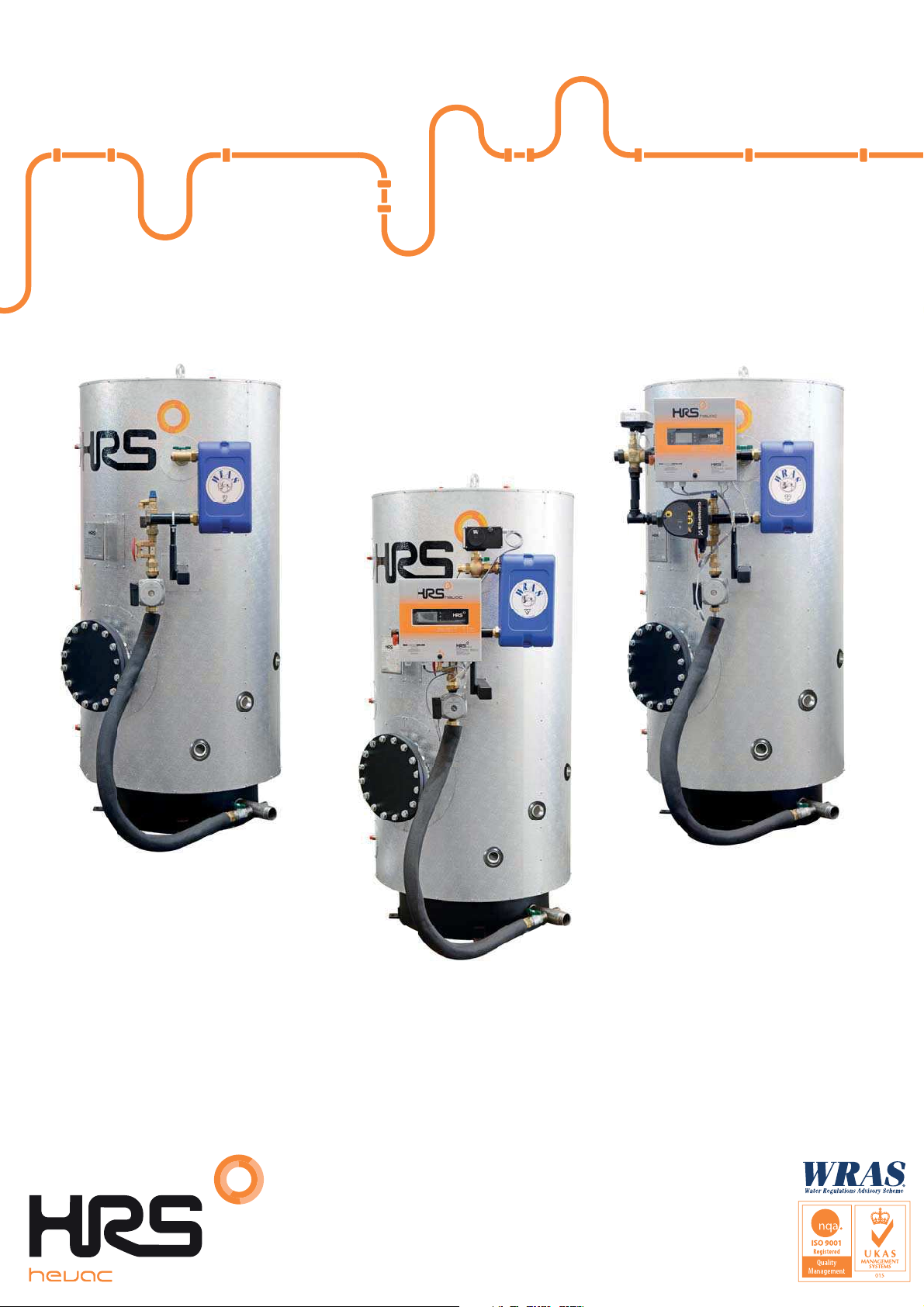
HRS AQUASAVE 6 Bar Range
6 bar Storage – 600 to 2,000 Litres
Operating & Instruction Manual
A60B
No Controls
A63B
3 Port Control
A62B
2 Port Control
Head Office
10-12 Caxton Way, Watford.
WD18 8JY t. 01923 232335
mail@hrs.co.uk www.hrshevac.co.uk
North & Factory
No 1 Rosemount Works, Elland
HX5 0EE t. 01422 317070
HRS Hevac Ltd AquaSave A6 Range
Installation, Operating & Instruction Manual
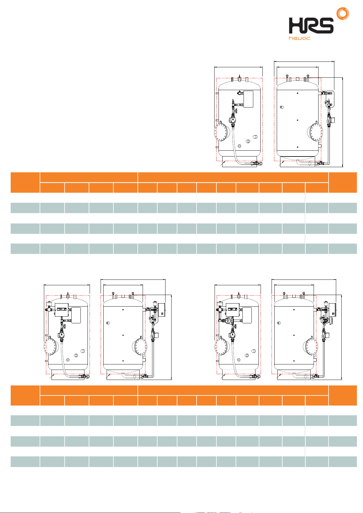
AquaSave A60B Dimensional Details
7
39 37
9
C
D B
9
7
Primary Inlet1
2
Primary Outlet
3 Secondary Flow
4 Secondary Return
6
6
4
5 Cold Feed
1111
6
A60B
6
1010
4
6
Instrument Connections (3-off)
7
Gauge Connections
8
Immersion Heater(s) - See Table
Safety Valve Connection(s) - Subject to Duty
9
10
Inspection Opening (DN250)
50mm Mineral Wool Insulation c/w Al. Stucco Cladding
11
Volume
(Litres)
600
800 1965 965 1205 1" 2" 1/2" 1/2" 3/8" 2" 295
1000 1945 1050 1305 1" 2" 1/2" 1/2" 3/8" 2" 335
1250 2020 1135 1405 1"
1500 2020 1220 1505
A B C D 1 2 3 4 5 6 7a 7b 8
1910 880 1105 1" 2"
700
800
900
1000
1"
1"
1"
1"
1100 1" 1" 1"2" 2" 1/2" 1/2" 3/8" 2" 400
6
8
8
6
8
5
Connections (Screwed BSP F)Dimensions
1"
1"
1"
1"2"
1/2" 1/2" 3/8" 2" 260
2"
2"
2"
2" 1/2" 1/2" 3/8" 2" 365
2000 2275 1305 1605 1200 1" 1" 1"2" 2" 1/2" 1/2" 3/8" 2" 540
1
2
A
Weight
(kg)
AquaSave A62B & A63B Dimensional Details
7
39 37
9
1
4
6
8
8
6
Volume
(Litres)
600 1910 910 1265 1" 2" 1/2" 1/2" 3/8" 2" 280
800 1965 965 1365 1" 2"
1000 1945 1050 1465 1" 2" 1/2" 1/2" 3/8" 2" 355
1250 2020 1135 1565 1"
1500 2020 1220 1665
8
5
1111
A B C D 1 2 3 4 5 6 7a 7b 8
C
DB
9
7
6
2
6
1010
6
4
A
1
2
6
6
Connections (Screwed BSP F)Dimensions
700
800
900
1000
1"
1"
1"
1"
1"
1"
1"
1"2"
1100 1" 1" 1"2" 2"
C
DB
7
39 37
9
8
8
8
5
4
1111
9
7
6
6
A63BA62B
6
2"
1/2" 1/2" 3/8" 2" 315
2"
2"
2"
1/2" 1/2" 3/8" 2" 385
1/2" 1/2" 3/8" 2" 420
1010
4
A
Weight
(kg)
2000 2275 1305 1765 1200 1" 1" 1"2" 2"
1/2" 1/2" 3/8" 2" 560
2 of 58 t.01923 232335 www.hrshevac.co.uk

HRS Hevac Ltd AquaSave A6 Range
Installation, Operating & Instruction Manual
Contents
Product overview .................................................................................................................. 51
1.1 Working pressure and temperature ...........................................................................................................6
1.2 Packing format ...........................................................................................................................................6
Options .................................................................................................................................. 72
2.1 A60B No Controls ................................................................7
2 B26A2.2 Port Control Valve
2.3 A63B ................................................................................................ .................................................8
3 Port Control Valve
Installation ............................................................................................................................. 93
3.1 Siting ..........................................................................................................................................................9
3.2 Hydraulic connections ...............................................................................................................................9
3.3 Basic assembly instructions .......................................................................................................................9
3.4 Commissioning ....................................................................................................................................... 10
Setting the DHW flow rate .................................................................................................. 114
Electrical connections ........................................................................................................ 125
5.1 A60B ................................................................................................ ............................................................... 12
5.2 A62B & A63B ................................................................................................................................................................... 12
5.3 Electrical power ratings table ................................................................................................................. 12
5.4 Current limiting fuses .............................................................................................................................. 12
Electrical installation of control box, A62B & A63 only ................................................... 136
6.1 Controller components ........................................................................................................................... 13
6.2 Electrical wiring diagram, A62B ................................................................ ..................................................................... 14
6.3 Electrical wiring diagram, A63B ................................................................ ..................................................................... 15
User instruction operator control panel Micro 3000 ......................................................... 167
7.2 Home screen .......................................................................................................................................... 17
7.3 Command symbols ................................................................................................................................. 17
7.4 Password and login ................................................................................................................................ 17
7.5 Setting the time and date ....................................................................................................................... 18
7.6 Changing the date format ....................................................................................................................... 18
7.7 Setting the daylight saving time .............................................................................................................. 18
7.8 Saving changes ...................................................................................................................................... 18
End user mode .................................................................................................................... 198
8.1 Set the hot water temperature ................................................................................................................ 19
8.2 Time programs ....................................................................................................................................... 19
8.3 Changing time and temperature in a time program................................................................................ 20
8.3.1 Special days ...................................................................................................................................... 20
8.4 Making a quick temperature change ...................................................................................................... 21
Technician menu ................................................................................................................ 229
9.1 Login ....................................................................................................................................................... 22
9.2 The technician Main menu ..................................................................................................................... 22
9.3 Configuration menu ................................................................................................................................ 23
9.4 S1 Menu Secondary Outlet .................................................................................................................... 24
9.5 Thermal Treatment Menu ....................................................................................................................... 24
9.6 Safety
9.7 Eco-Booster Function ............................................................................................................................. 25
9.8 Fouling function ...................................................................................................................................... 26
9.9 230V Triac menu .................................................................................................................................... 26
9.10 Autotest menu ........................................................................................................................................ 27
9.11 Clear alarm menu ................................................................................................................................... 28
Function....................................................................................................................................... 25
................................................................................................
................................................................
...............................................................
..........7
Service Menu ................................................................................................................. 2910
10.1 Change password for technician level ................................................................................................... 29
10.2 Login installer ......................................................................................................................................... 29
10.3 Menu Continue ....................................................................................................................................... 30
10.4 Operating hours ...................................................................................................................................... 31
10.5 Trending parameters menu .................................................................................................................... 32
10.6 Display the trend buffer ................................
...............................................................
........................... 33
t.01923 232335 www.hrshevac.co.uk 3 of 58

HRS Hevac Ltd AquaSave A6 Range
Installation, Operating & Instruction Manual
10.7 Point Data............................................................................................................................................... 33
Alarm menu ................................................................................................................... 3411
Parameters’ list................................................................................................................... 3512
Factory reset ....................................................................................................................... 3613
Modbus................................................................................................................................ 3714
14.1 Modbus communication ......................................................................................................................... 37
14.2 Connecting multiple Micro 3000 control boxes ...................................................................................... 37
14.3 Change Modbus parameters.................................................................................................................. 38
14.4 Modbus slave communication parameters............................................................................................. 39
Trouble shooting ................................................................................................................4015
Maintenance and repairs .................................................................................................... 4116
16.1 Antibacterial treatment of the AquaSTOR ............................................................................................ 42
16.2 Clean the copper brazed plate heat exchangers .................................................................................. 43
16.3 Open the control box .............................................................................................................................. 44
16.4 Set the number of pumps ....................................................................................................................... 44
16.5 Pumps’ number ...................................................................................................................................... 45
16.6 Add an extra sensor ............................................................................................................................... 45
16.7 Connect to 230V Triac output................................................................................................................. 45
16.8 Add relay 1 and relay 2 .......................................................................................................................... 45
16.9 Add a remote control contact ................................................................................................................. 45
Assembly of the charging kit to the AquaSTOR ............................. ................................. 4617
17.1 Attaching the heat exchanger insulation ................ ................................................................................ 49
17.2 Wiring the seconary shunt pump ........................................................................................................... 50
Flowcharts...........................................................................................................................5118
18.1 Flowchart A60B ................................................................ ........................................................................................ 51
18.2 Flowchart A62B ...................................................................................................................................... 52
18.3 Flowchart A63B ............................................. ................................................................ ....................................................... 53
Wiring the charging pump.................................................................................................. 5419
Special instructions for options ........................................................................................ 5520
20.1 Special instructions for A62B ................................................................ .................................................................. 55
20.1.1 Electrical wir
20.1.2 Wiring diagram .................................................................................................................................. 55
ing ................................................................................................................................. 55
Commissioning report........................................................................................................ 5621
Declaration of Conformity .................................................................................................. 5722
Warranty.............................................................................................................................. 5823
23.1 Spare parts............................................................................................................................................. 58
23.2 How to contact HRS Hevac .................................................................................................................... 58
4 of 58 t.01923 232335 www.hrshevac.co.uk
HRS Hevac Ltd AquaSave A6 Range
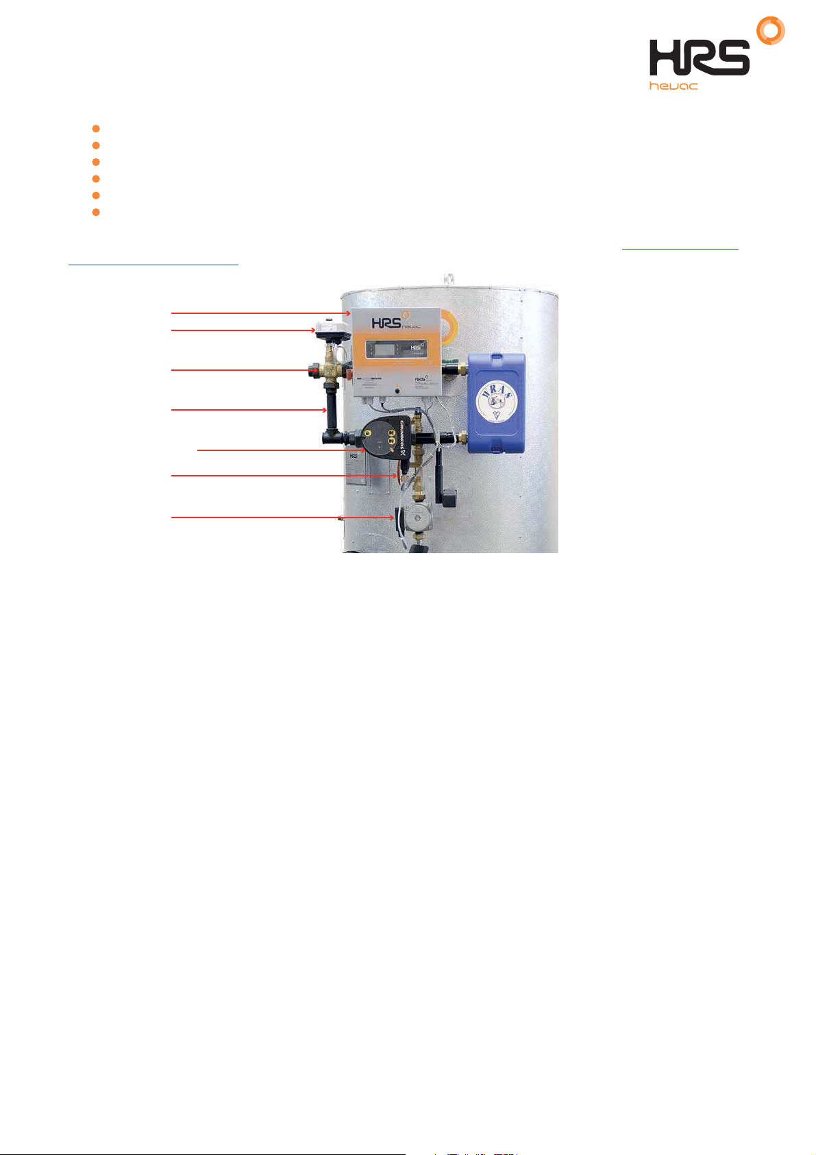
1.
Storage tank, stainless steel storage tank
with a heat-insulated cover
5.
Connector hose between tank and charging
pump, thermally-insulated
2.
Plate heat exchanger, 316-grade stainless steel
copper-welded
3.
Balancing valve
6.
Charging kit support
4
Charging pump
Installation, Operating & Instruction Manual
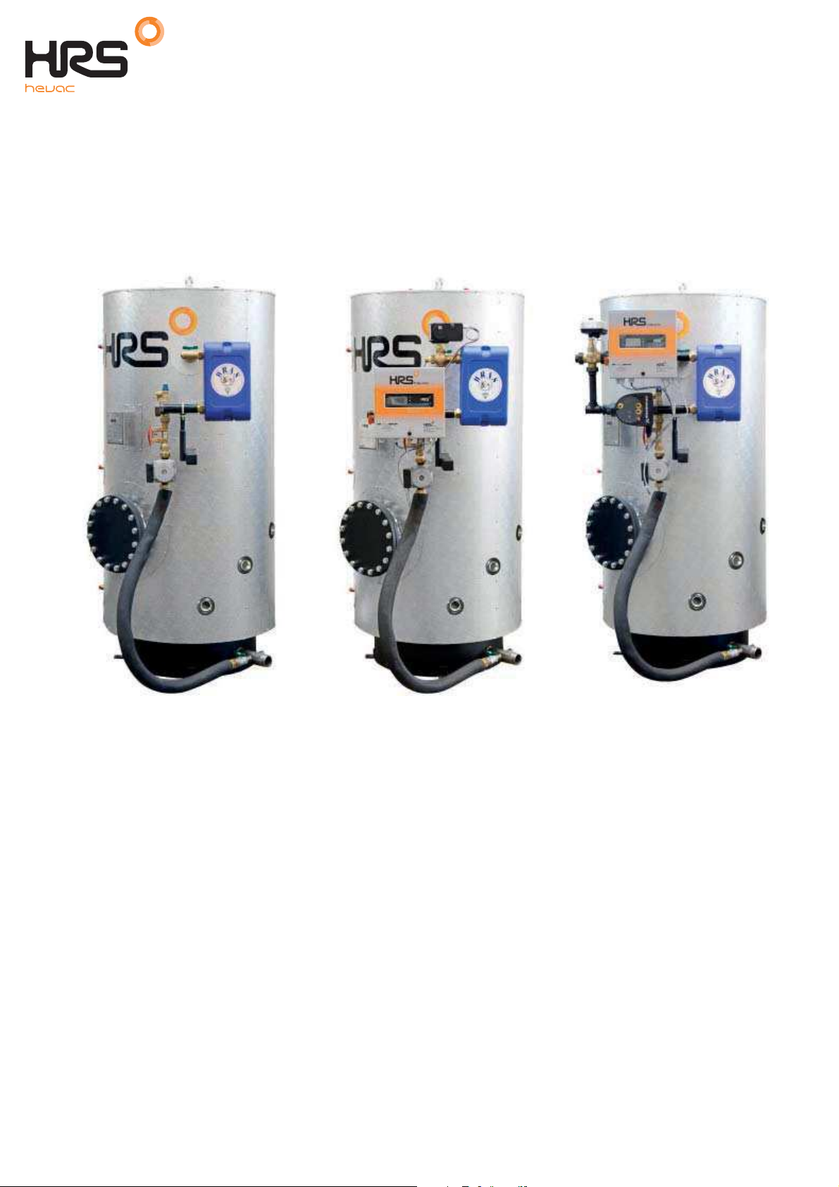
Product overview1
The basic version of the HRS Hevac AquaSave DHW heater, indirect (semi-instantaneous) system
comprises:
3
6
4
1
5
A60B
No Controls
2
22
3
3
4
6
4
6
11
5
A62B
2 Port Control
5
A63B
3 Port Control
t.01923 232335 www.hrshevac.co.uk 5 of 58

HRS Hevac Ltd AquaSave A6 Range
AquaSave
Model Type
PRIMARY SIDE
SECONDARY SIDE
Max working
pressure (bar)
Max temperature
(°C)
Max working
pressure (bar)
Max temperature
(°C)
A60B
10
110695
A62B10110695
A63B10110695
Installation, Operating & Instruction Manual
1.1 Working pressure and temperature
1.2 Packing format
AquaSave is delivered in two packages:
storage tank
exchanger kit
6 of 58 t.01923 232335 www.hrshevac.co.uk

Options2
Actuator
Control valve
Control box mounted on its
support
There are three different control systems available as option.
2.1 A60B - No Controls
Supplied with only the secondary charging circuit.
HRS Hevac Ltd AquaSave A6 Range
Installation, Operating & Instruction Manual
Follow the assembly instructions in
Primary flow connection
Primary return connection
17 Assembly of the
charging kit to the AquaSTOR
2.2 A62B - 2 Port Control Valve
One 2-port PN25 valve body
One Pt100 temperature sensor
One actuator, 230V 3 points with return to zero
One PID controller box with piping and support, depending on the model selected
The primary circuit is pre-assembled on the exchanger. Follow the assembly instructions in
charging kit to the AquaSTOR
17 Assembly of the
t.01923 232335 www.hrshevac.co.uk 7 of 58
HRS Hevac Ltd AquaSave A6 Range
Installation, Operating & Instruction Manual
2.3 A63B - 3 Port Control Valve
One 3-port control valve, PN16
One primary shunt pump, PN10
One actuator, 24V AC feed-in and 0-10V DC controller current
One PID controller box with Pt100 temperature sensor
Primary piping, sized differently according to heat exchanger type
Control box support
The primary circuit is pre-assembled on the exchanger. Follow the assembly instructions in
charging kit to the AquaSTOR.
Control box
Actuator
Control valve
Piping
Primar
y shunt pump
Balancing valve
Charging pump
17 Assembly of the
8 of 58 t.01923 232335 www.hrshevac.co.uk
HRS Hevac Ltd AquaSave A6 Range
Installation, Operating & Instruction Manual
Installation3
3.1 Siting
The AquaSave hot water heater shall be installed in a dry place where room temperature is below 40°C,
and ideally in ventilated premises.
AquaSave is placed preferably on a sub-base footing.
3.2 Hydraulic connections
Connect the charging kit (exchanger + control valve + charging pump) to the storage tank using the interlink kit.
Make arrangements for fitting the insulation onto the tank before connecting up the piping.
The indirect AquaSave module can run without a recirculation system fitted.
To avoid creating a galvanic coupling, check that the materials used in the installation have similar corrosion
potentials.
3.3 Basic assembly instrustions
Assembly: refer to the full instructions given in
Connect the primary supply and return connections.
Connect the cold water supply, hot water outlet and the recirculation system to the tank.
17 Assembly of the charging kit to the AquaSTOR.
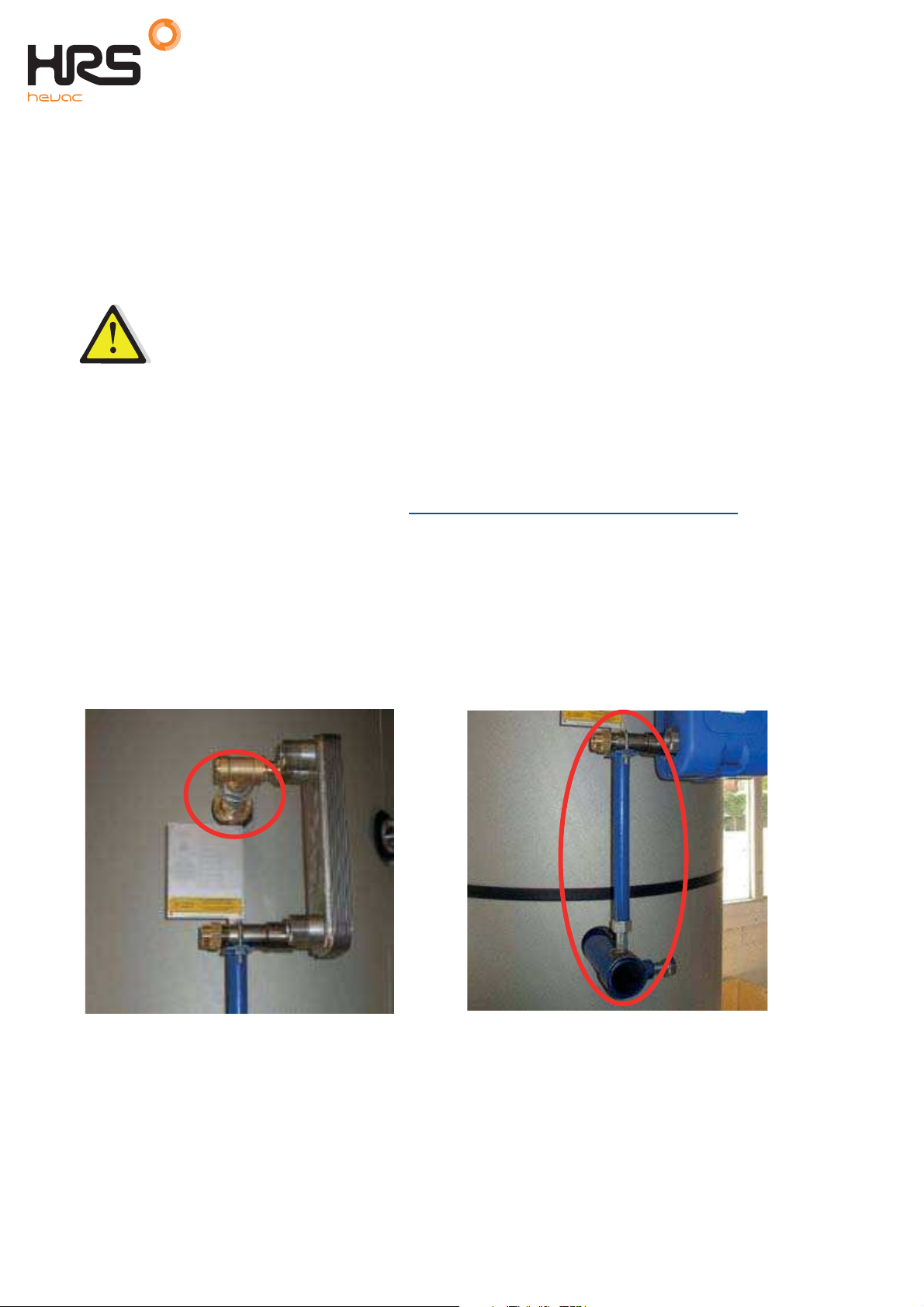
Fit the tank with a safety valve, a drain valve in the top section and a draw-off in the bottom section.
NOTE: The valve is a compulsory fixture that has to be pre-loaded at the storage tank operating pressure.
NOTE: The safety valve on the charging kit only protects the secondary system – it will neither protect nor
surge-feed the installation and the volume stored, in correspo
The safety valve shall have the same diameter as the cold water inlet fixture
Top section connection Exchanger support + accessories
ndence with local rules.
t.01923 232335 www.hrshevac.co.uk 9 of 58

HRS Hevac Ltd AquaSave A6 Range
Installation, Operating & Instruction Manual
Bottom section connection, shut-off valve inserted between the conduit hose and the cold water inlet fixture.
3.4 Commissioning
Flood the various circuits and flush-bleed the pumps.
Power-up.
Set the secondary (charging) flow rate using the setting valve (read-off + setting)
NOTE: When first heated, the water in the tank will expand, increasing the pressure. A water hammer-arrestertype surge tank qualified for DHW systems may be fitted to prevent the relief valve from opening. Check the
water network pressure.
10 of 58 t.01923 232335 www.hrshevac.co.uk
HRS Hevac Ltd AquaSave A6 Range
Installation, Operating & Instruction Manual
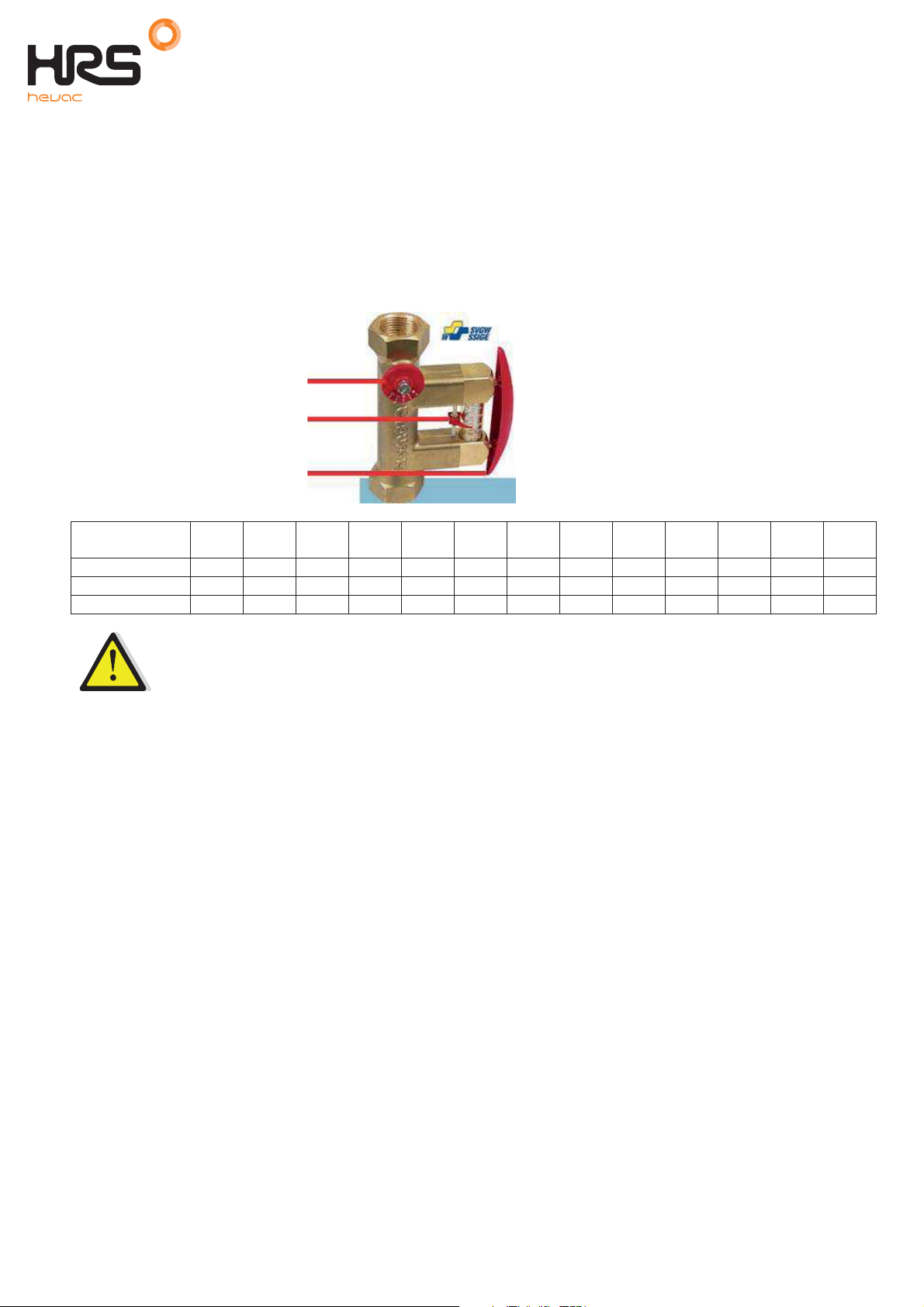
Setting the DHW flow rate 4
The secondary DHW flow rate is set with the tank full and the primary circuit at nominal operating temperature
and at the available exchanger power capacity required for the generator.
1. Fully open up the control valve on the primary side.
2. If a 3-way control valve is fitted, wait for it to open completely.
3. Adjust the secondary flow circuit, as set out in the table below.
The flow rate can be read by pressing on the red pushbutton and readi
float.
Flow controller
Read-off index marker
Read-off pushbutton
P(kW)
DHW T(°C)
10 > 55°C 9.5 13 16 19 22 25.5 28.5 32 40 48 56 63 76
10 > 60°C 8.5 11.5 14 17 20 23 26 28 35 43 50 57 68
5 > 70°C 6 9 11 13 15 17 20 22 27 33 38 44 53
30 40 50 60 70 80 90 100 125 150 175 200 240
The recirculation flow rate has to be 60% maximum of the secondary flow rate.
ng the index marker against the
t.01923 232335 www.hrshevac.co.uk 11 of 58

HRS Hevac Ltd AquaSave A6 Range
Installation, Operating & Instruction Manual
Electrical connections5
All devices shall be connected up in compliance with the governing standards.
All work on control box and other electrical components must be done by qualified people.
The main electrical box should be equipped with short-circuits protection
5.1 A60B
The charging pump has to be powered constantly.
5.2 A62B & A63B
For more information about the Operator Control box, see chapter 6 Electrical installation of control box, option,
and forward.
Power the control box via a single-phase 230 V + ground.
Electrical system components pre-cabled according to the hardware ordered.
5.3 Electrical power ratings table
Primary pump
Unit Type
A60B
80 - 200 kW
A60B
>200 kW
A62B
80 - 200 kW
A62B
>200 kW
A63B
80 - 200 kW
A63B
>200 kW
1)
The electrical consumption of the control box and the actuator is 10W, 0.3A.
Figures are rounded up to the nearest value.
2)
Has no control box
type
- - UP20-45N 115W 0.5A 125W
- - UPS 32-80N 240W 1.05A 245W
- - UP20-45N 115W 0.5A 125W
- UPS 32-80N 240W
Magna 1 32-80 151W
Magna 1 32-80 151W
Primary pump
consumption.
W, A
1.22A
1.22A
SINGLE-PHASE 230 VOLTS + GROUND
Secondary
pump type
UP20-45N 115W
UPS 32-80N 240W
Secondary
pump
consumption,
W
1.05A
0.5A
1.05A
TOTAL +
Control box
2)
0.6A
2)
1.15A
0.8A
250W
1.17A
266W
2.02A
391W
2.57A
1)
5.4 Current limiting fuses
Power cards are equipped with fuses, labelled FU1 to FU5 on the printed circuit.
Fuse FU1 FU2 FU3 FU4 FU5
Protection
Size (mm)
Calibre
Voltage
Safety fuses are supplied inside the control box.
PUMP 1 N/A PUMP N/A PCB
6.3x32 6.3x32 6.3x32 6.3x32 6.3x32
2.5A 2.5A 250mA
250V 250V 250V 250V 250V
12 of 58 t.01923 232335 www.hrshevac.co.uk
HRS Hevac Ltd AquaSave A6 Range
Installation, Operating & Instruction Manual
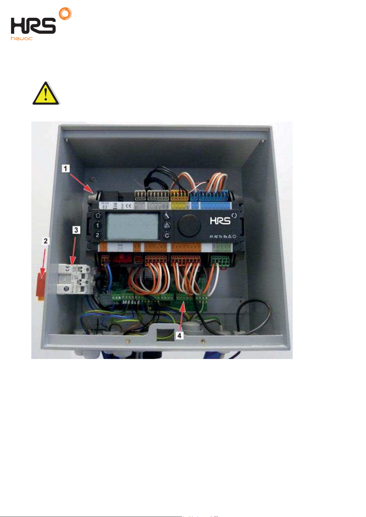
Electrical installation of control box, A62B & A63B only 6
Power supply the control box with 230VAC 50 Hz. The control box with the controller Micro 3000 is called the
secondary control box.
Human protections and protection against short circuits and over intensity must be installed in the
m
ain electric box.
6.1 Controller components
1 Controller, Micro 3000 3 Power Supply contact
2 Main switch 4 Printed Circuit Board
t.01923 232335 www.hrshevac.co.uk 13 of 58
HRS Hevac Ltd AquaSave A6 Range
Installation, Operating & Instruction Manual
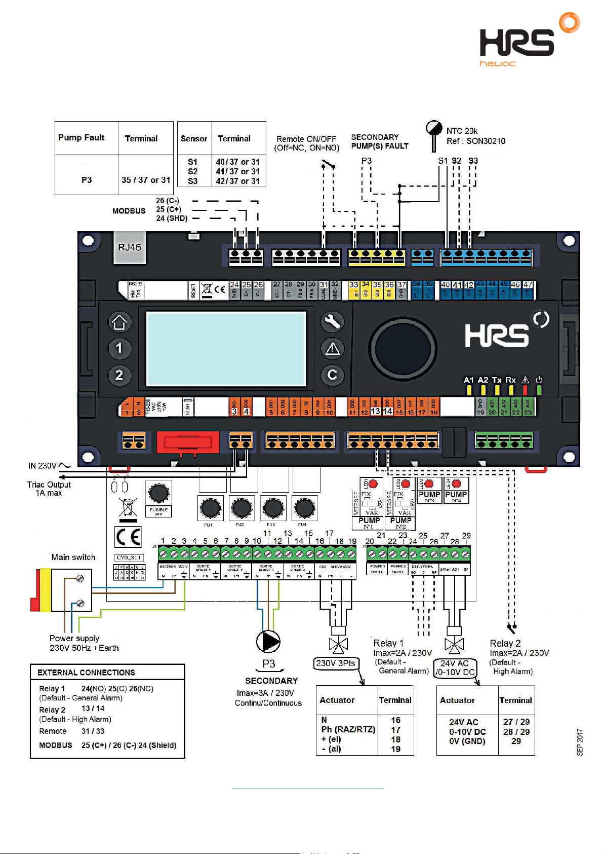
6.2 Electrical wiring diagram A62B
NOTE: When the remote control contact is open, the unit operates normally. If it is closed the unit is in standby.
NOTE: *) 230V 3pts actuator wiring, see
2
0 Special instructions for options
.
14 of 58 t.01923 232335 www.hrshevac.co.uk

HRS Hevac Ltd AquaSave A6 Range
Installation, Operating & Instruction Manual
6.3 Electrical wiring diagram A63B
NOTE: When the remote control contact is open, the unit operates normally. If it is closed the unit is in standby.
t.01923 232335 www.hrshevac.co.uk 15 of 58
HRS Hevac Ltd AquaSave A6 Range
Installation, Operating & Instruction Manual
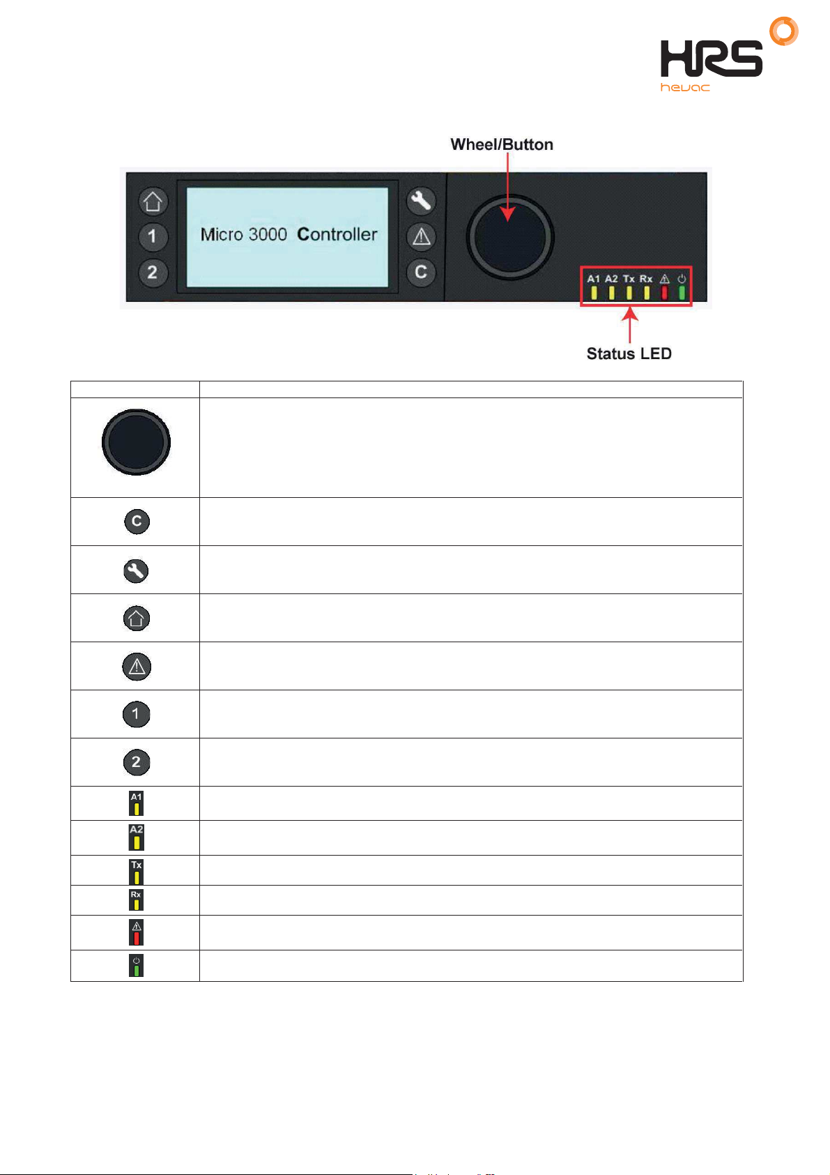
User instruction operator control panel Micro 3000 7
Button Function
Rotary button, wheel, for scrolling through the menus. Access sub-menus and change
settings by pressing it.
To activate the line or change a highlighted value, simply press the wheel.
Works like an Enter key.
Press to exit a level and return to the previous menu/parameter.
Works like an ESC key.
Press to access the maintenance / monitoring menu.
NOTE: Requires a password.
Press to go to the Home screen, Main Menu
Press to access the Alarm Menu.
Not used
Not used
Relay 1 activated.
Relay 2 activated..
Active data transmission
Active data reception
Alarm indicator
The Control box is switched on.
16 of 58 t.01923 232335 www.hrshevac.co.uk
HRS Hevac Ltd AquaSave A6 Range
Installation, Operating & Instruction Manual
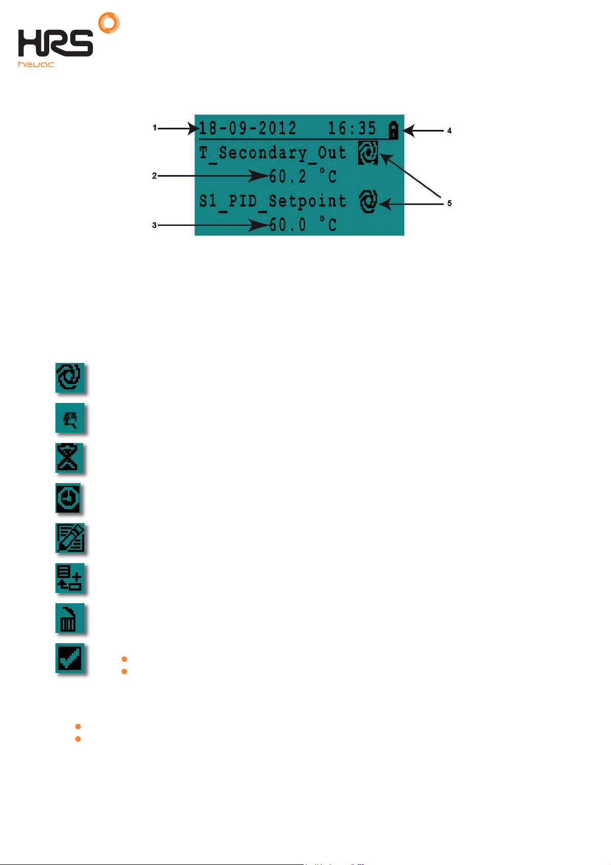
7.2 Home screen
When starting up the Micro 3000 controller this menu displays on them screen. The menu is called the Home
screen.
1 Date / hour 4 Access level:
Locked=restricted /
Key= total (3333)
2 DHW Temperature 5 Command symbols
3DHW Set point
: if there is an ongoing alarm when starting up the controller AquaSave, an alarm text will be
NOTE
displayed on the screen. Press the House button to enter the Home screen.
7.3 Command symbols
Auto
Datapoint is in automatic operation and can be switched into manual operation.
Manual
Datapoint in manual operation and can be switched into automatic operation.
Today function
Datapoint value can be overridden for a particular time period within the next 24 hours.
Datapoint must have a daily time program assigned.
Time Program
Datapoint has a daily time program assigned. Daily time program can be selected and edited.
Edit
Item (datapoint, time program etc.) can be edited.
Add
Item (datapoint, time program etc.) can be added to a list e.g. datapoint can be put to a list of
trended datapoints.
Deleted
Item can be deleted
Enable/disable
Checked: item is enabled
Unchecked: item is disabled
7.4 Password and login
The controller has password protection, allowing accesses to different menus.
End user level
Technician level
- requires no login. Marked with a locker in the upper right corner.
- access to all menus requires login. Marked with a key in the upper right corner.
t.01923 232335 www.hrshevac.co.uk 17 of 58
HRS Hevac Ltd AquaSave A6 Range
Installation, Operating & Instruction Manual
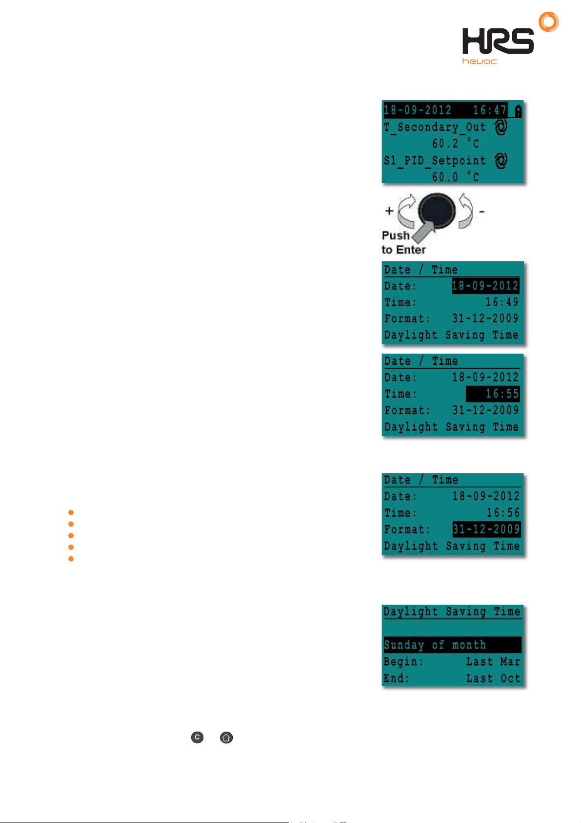
7.5 Setting the time and date
1. Turn the wheel anticlockwise to highlight the line with time and
date at the top of the screen. Press the wheel to enter the
Date/Time menu.
2. Press the wheel to change the first variable, the year.
3. When the year flashes, increase or reduce the set value by
rotating the wheel.
Once the right value is displayed, press the wheel to confirm the
setting. Next parameter to change starts to flash.
4. Proceed in the same way to set the month, date
and time (hour: minute).
7.6 Changing the date format
In the Date/Time menu the date format can be changed.
Choose between the following formats:
yyyy-mm-dd
mm-dd-yyyy
dd-mm-yyyy
dd.mm.yyyy
dd/mm/yyyy
7.7 Setting the daylight saving time
Summer time
Changing between summer/winter time can be automatic or turned off.
You can also define the dates for changes if they are altered.
The default settings for summertime is:
Last Sunday in March to last Sunday in October.
7.8 Saving changes
Once a value has been changed and confirmed by pressing the wheel, the corresponding change will be
immediately updated. Press the or to return to the home screen.
18 of 58 t.01923 232335 www.hrshevac.co.uk
 Loading...