

HR AD-340 User Manual
UMA1186 REV A
Order toll-free in the U.S. 800-959-6439
FREE technical support, Call 714-641-6607 or fax 714-641-6698
Address: Hall Research, 1163 Warner Ave. Tustin, CA 92780
Web site: www.hallresearch.com E-mail: info@hallr esearch.com
CUSTOMER
SUPPORT
INFORMATION
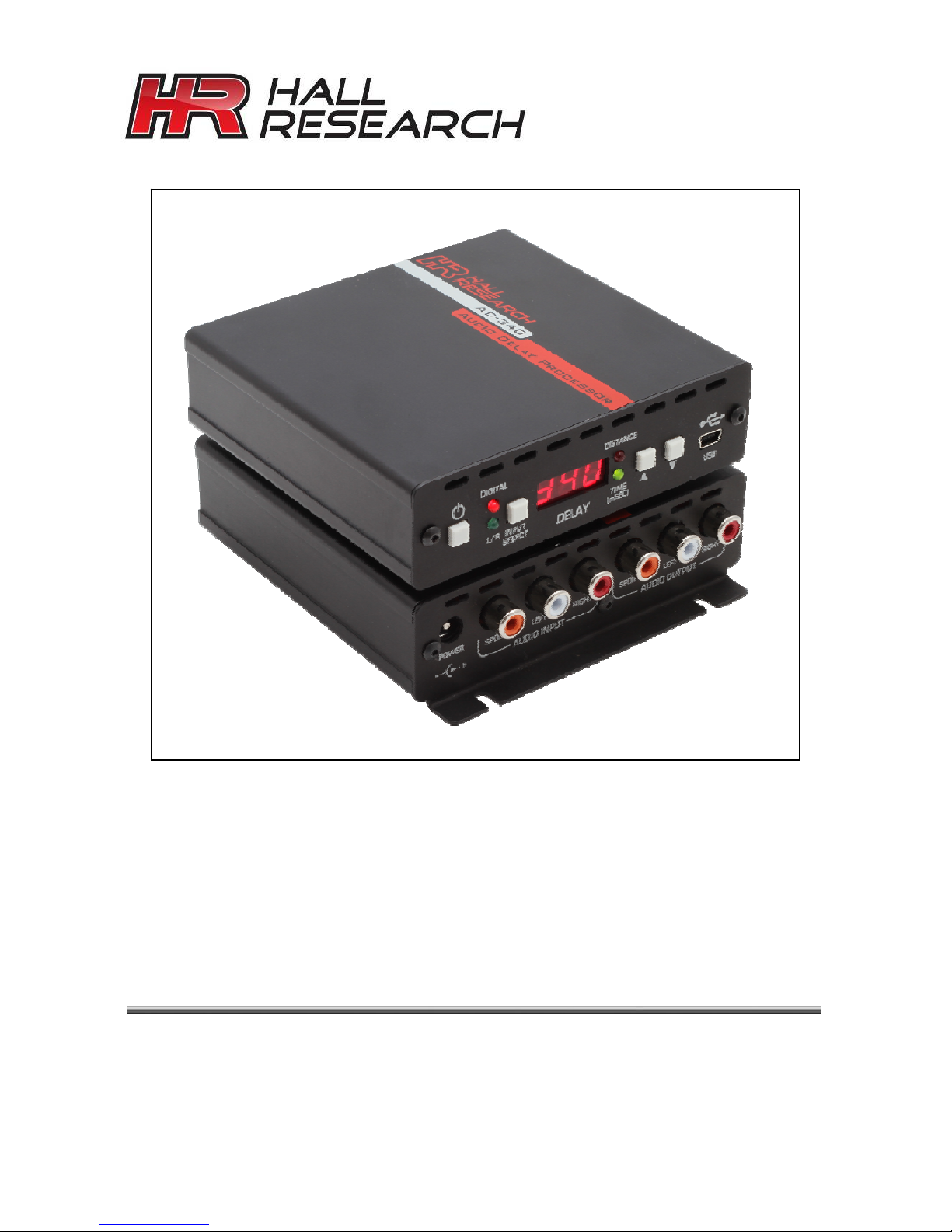
Model AD-340
Universal Audio Delay Processor
User’s Manual


Universal Audio Delay Processor
1
Contents
1 Introduction.....................................................................................2
1.1 General........................................................................................................2
1.2 Features.......................................................................................................3
2 Installation.......................................................................................4
2.1 Package Contents ....................................................................................... 4
2.2 Front and Rear Panel..................................................................................4
2.3 Input and Output Connections.....................................................................5
3 Configuration & Operation.............................................................6
3.1 Front-Panel Button Operation......................................................................6
3.2 Windows-Based Software GUI.................................................................... 7
3.2.1 Installation................................................................................................. 7
3.2.2 Operation..................................................................................................8
3.3 Audio Configuration...................................................................................12
3.3.1 General...................................................................................................12
3.3.2 Sampling Rates ...................................................................................... 13
3.3.3 Audio Mute Function...............................................................................13
3.3.4 Analog Input/Output Volume Control......................................................14
3.3.5 Delay Function........................................................................................14
3.3.6 Factory Default Settings ......................................................................... 17
4 Troubleshooting............................................................................ 17
4.1 FAQ...........................................................................................................17
4.2 Contacting Hall Research..........................................................................18
4.3 Shipping and Packaging............................................................................18
5 Specifications................................................................................ 19
6 Trademarks....................................................................................19
FCC Statement
This equipment generates, uses, and can radiate radio frequency energy and if not installed and used properly,
that is, in strict accordance with the manufacturer’s instructions, may cause interference to radio communication.
It has been designed to comply with the limits for a Class A computing device in accordance with the
specifications in Subpart B of Part 15 of FCC rules, which are intended to provide reasonable protection against
such interference when the equipment is operated in a commercial environment. Operation of this equipment in
a residential area is likely to cause interference, in which case the user at their own expense will be required to
take whatever measures may be necessary to correct the interference.
Changes or modifications not expressly approved by the party responsible for compliance could void the user’s
authority to operate the equipment.
Model AD-340
2
1 Introduction
1.1 General
Thank you for purchasing the professional and compact AD-340 Audio Delay
Processor from Hall Research. This User’s Manual applies to both the AD-340
Audio Delay Hardware and the Windows-based Audio Delay Software Graphical
User Interface (GUI).
The AD-340 can be configured directly from the Front Panel Push Buttons or
from the GUI when the AD-340 is connected to a Windows HOST PC with a USB
cable. The Software GUI for the AD-340 is designed to be an intuitive and
powerful user interface, and the front panel is simple and easy to use.
The AD-340 Audio Delay Processor provides both Analog (Left and Right Stereo
Channels) and Digital Audio Inputs and Outputs, including CD, DVD or Blu-Ray
Disc quality audio processing.
The user controllable Delay Functions allow an adjustable digital delay for
audio/video synchronization/timing alignment and for acoustic external delay
alignments for speaker systems located at different distances relative to the
listeners.
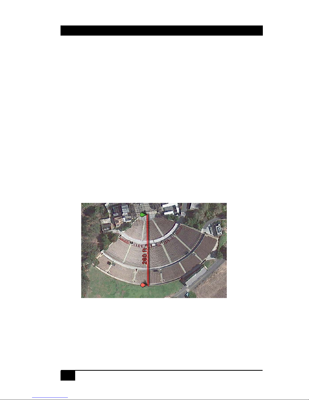
The AD-340 is equipped to adjust for virtually any environment. Even the Verizon
Amphitheater one of the largest venues in Southern California, is well within the
capabilities of this unit, which can adjust for distances of up to 510 feet (155
meters)

Universal Audio Delay Processor
3
1.2 Features
• Stereo Analog Input and Outputs (left and right channel) – RCA connectors
• Analog Audio Compatible with 2 Vrms Line level for CD, DVD and BD Players
• Digital Audio Input and Outputs - SPDIF over coaxial - for RCA connector
• Digital Audio (IEC60958) supporting standard CD, DVD and BD sample rates
at 32 kHz, 44.1 kHz, 48 kHz and 96 kHz
• Supports 2-channel linear PCM digital audio and 5.1 Channel Dolby Digital
and DTS encoded bitstreams.
• Converts linear PCM digital input to analog output – and analog inputs to
LPCM digital output
• User selectable digital delay functions for audio delay in millisecond, video
frames and external delay set in feet or meter
• Delay time selectable from 0 to 510 milliseconds in 1 msec increments– or 0 to
16 video frames (both 50 Hz and 60 Hz TV-systems)
• Delay time for analog or digital at 48 Hz sampling rate – up to 340 millisecond
• External delay up to 510 feet or 155 meter
• Auto-detection of digital frame rates and bitstream formats like Dolby Digital
and DTS - Indicators for SPDIF input signal quality.
• Ground Loop Isolated Analog inputs and Transformer coupled SPDIF output
• Adjustable audio input volumes for MIC inputs (with RCA adapters)
• Adjustable analog audio output volumes
• User controllable muting: Auto-mute when changes are being made
• Advanced mode: automatic calculations of speed of sound based on user
selectable temperatures (Fahrenheit or Celsius)
• Powerful and intuitive front panel controls for configuration
• Auto-save of current configuration settings
• Windows based GUI for configuration control -
• Interface to HOST PC – via Mini-B USB connector - USB 2.0
• GUI: Save and Recall of configuration settings, Factory Default Reset
• Made in USA
Model AD-340
4
2 Installation
2.1 Package Contents
Your package should contain the AD-304 Audio Delay Processor, a Universal
power supply (6v DC @ 1.5A) with interchangeable connector blades for most
countries, a USB Cable with Mini-B Connector and this User’s Manual.
2.2 Front and Rear Panel
The AD-340 is in a 4-inch wide enclosure with mounting bracket on the rear
panel. All Analog and Digital Audio Inputs/Outputs and the power connections
are on the rear of the unit. The LEDs, 7-segment LED and Push Buttons and the
Mini-USB connector are on the front panel.
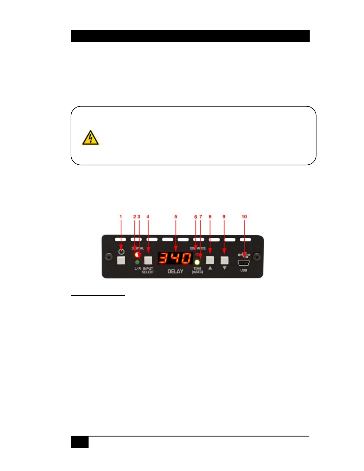
FRONT PANEL:
1. Power Switch: Standby Power switch
2. Red LED Indicator: Indicates Digital Audio Input
3. Green LED Indicator: Indicates Analog Audio Input
4. SELECT Switch: Selects the Audio Input Type
5. 7-segment LED: Displays Delay Values and Delay Type
6. Red LED Indicator: Indicates Distance as delay type (Feet
or Meters)
7. Green LED Indicator: Indicates Millisecond as delay Type
8. UP Switch: Increase Values
9. DOWN Switch: Decrease Values
10. Mini-B USB Connector: Connects to HOST PC
Notice
The unit can run from 6 to 9v DC power (center positive), current
requirement is 200 ma max. Use of any other voltage may cause
damage to the unit and void the warranty.
Universal Audio Delay Processor
5
REAR PANEL
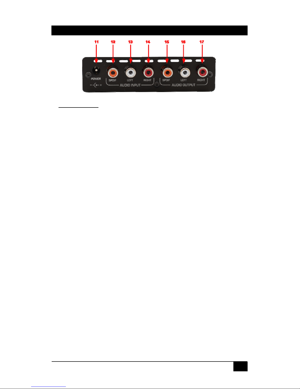
:
11. Power Connector: Connects to 6V Power Supply
12. SPDIF RCA Input: Digital Audio Input
13. Left RCA Input: Left Analog Audio Input
14. Right RCA Input: Right Analog Audio Input
15. SPDIF RCA Output: Digital Audio Output
16. Left RCA Output: Left Analog Audio Output
17. Right RCA Output: Right Analog Audio Output
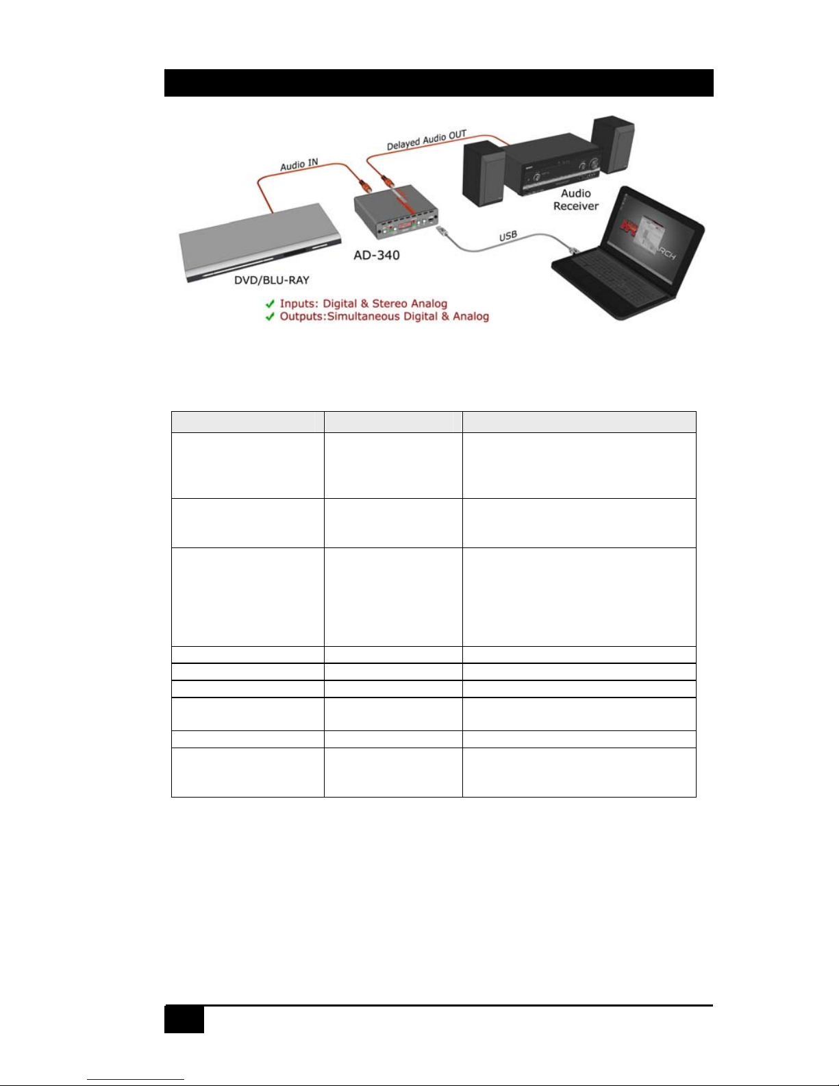
2.3 Input and Output Connections
Using RCA Coaxial cables (left/right channels usually marked
white/red), connect the analog input connectors to the audio source –
typically a CD, DVD or BD players, or a PC. A Microphone (MIC) input
with an RCA adapter can also be connected. Using an RCA Coaxial
cable (Digital usually marked orange); connect the Digital Audio to the
audio source.
Using RCA Coaxial Cables connect the outputs to an Audio/Video
receiver or similar audio equipment. Audio Equipment with DTS
Decoder and Dolby Digital Decoder is required to decode Digital
Bitstreams encoded in the DTS Surround (5.1) and Dolby Digital
Stereo or Surround (5.1) formats.
Plug the power supply to the unit. Use only the supply that came
with the unit.
Install the Windows-Based Software GUI on the Host PC.
Connect the Windows Host PC to the AD-340 with the provided USB
Cable with the Mini-B USB Connector.
Note: Sound is output simultaneously on both the Analog and Digital outputs
ONLY when the Digital Input is LPCM.
Model AD-340
6
3 Configuration & Operation
3.1 Front-Panel Button Operation
Button Function Description
(1) POWER Standby
Power On/Off
Standby mode = USB inactive,
Audio non-functional (to
completely turn the unit off,
disconnect the power supply)
(4) SELECT Select ANALOG or
DIGITAL Input
(2) Red LED = DIGITAL
(3) Green LED = ANALOG
(4+8) SELECT + UP
or
(4+9) SELECT + DN
Select DELAY
TYPE
(toggle function)
Display shows:
SEC
= Millisecond
FEE
= Feet
d1S
= Meter (Distance)
F50
= Video Frames 50 Hz
F60
=Video Frames 60 Hz
(8) UP Increase Increase value by 1
(8) UP held down Increase Increase value by 10
(9) DOWN Decrease Decrease value by 1
(9) DOWN held
down
Decrease Decrease value by 10
(8+9) UP+DOWN Set to Zero Set Delay Values to ZERO
(5) 7-segment LED Display values (6) Red LED = Time (ms)
(7) Green LED = Distance (ft/m)
No LED = Frames
• When the Host PC GUI is active, configurations can be made from
either the Front Panel or the Software GUI. All configuration changes
are completely synchronized in real-time.
• The Unit will automatically memorize the current delay settings, audio
type, ADC/DAC gain settings and the mute status.
 Loading...