

CorTemp™
Wireless Temperature/Heart Rate
Monitoring System
Model No. HT150010/HT150009
Operational Instructions
Hardware
US Version 1.0 – December 2002
HQ, Inc.
210 9th Street Drive West
Palmetto, FL 34222
941-721-7588, ext. 11 • Fax 941 -729-5480
Email: HTI2000@gte. Net Website: HQInc. us

2
TABLE OF CONTENTS
I. System Overview Page 3
II. System Requirements Page 4
III. RF System Set-Up Page 4
III.1 CorTemp™ Page 4
III.2 RF Central Receiving Station Page 4
III.3 RF Remote Transmitter Page 5
III.4 Computer Page 5
III.5 Diagnostics System Test Page 7
III.6 CorTemp™/RF Remote
Transmitter Unit Placement Page 7
IV. RF Remote Transmitter Page 8
IV.1 Product Features Page 8
IV.2 Specifications Page 8
V. RF Central Receiving Station Page 9
V.1 PC Requirements Page 9
V.2 Product Features Page 9
V.3 Specifications Page 9
VI. Warranty Page 10
VII. Customer Service/Repair Page 10
FCC Notice
NOTE: This equipment has been tested and found to comply with the limits for a Class B digital device,
pursuant to part 15 of the FCC rules. These limits are designed to provide reasonable protection against
harmful interference in a residential installation. This equipment generates, uses and can radiate radio
frequency energy and, if not installed and used in accordance with the instructions, may cause harmful
interference with radio communications. However, there is no guarantee that interference will not occur
in a particular installation. If this equipment does harmful interference to radio or television, which
can be determined by turning the equipment off and on, the user is encouraged to try to correct the
interference by one or more of the following measures.
Reorient or relocate the receiving antenna.
Warning: FCC regulations state that any unauthorized changes or modifications to this equipment not
expressly approved by HQ, Inc. could void the user’s authorization to operate this equipment.
FCC ID# QQBHT130022
Increase the separation between the equipment and t he receiver.
Connect the equipment into an outlet on a circuit different from that to which the receiver is
connected.
Consult the dealer or an experienced radio/TV technician.
3
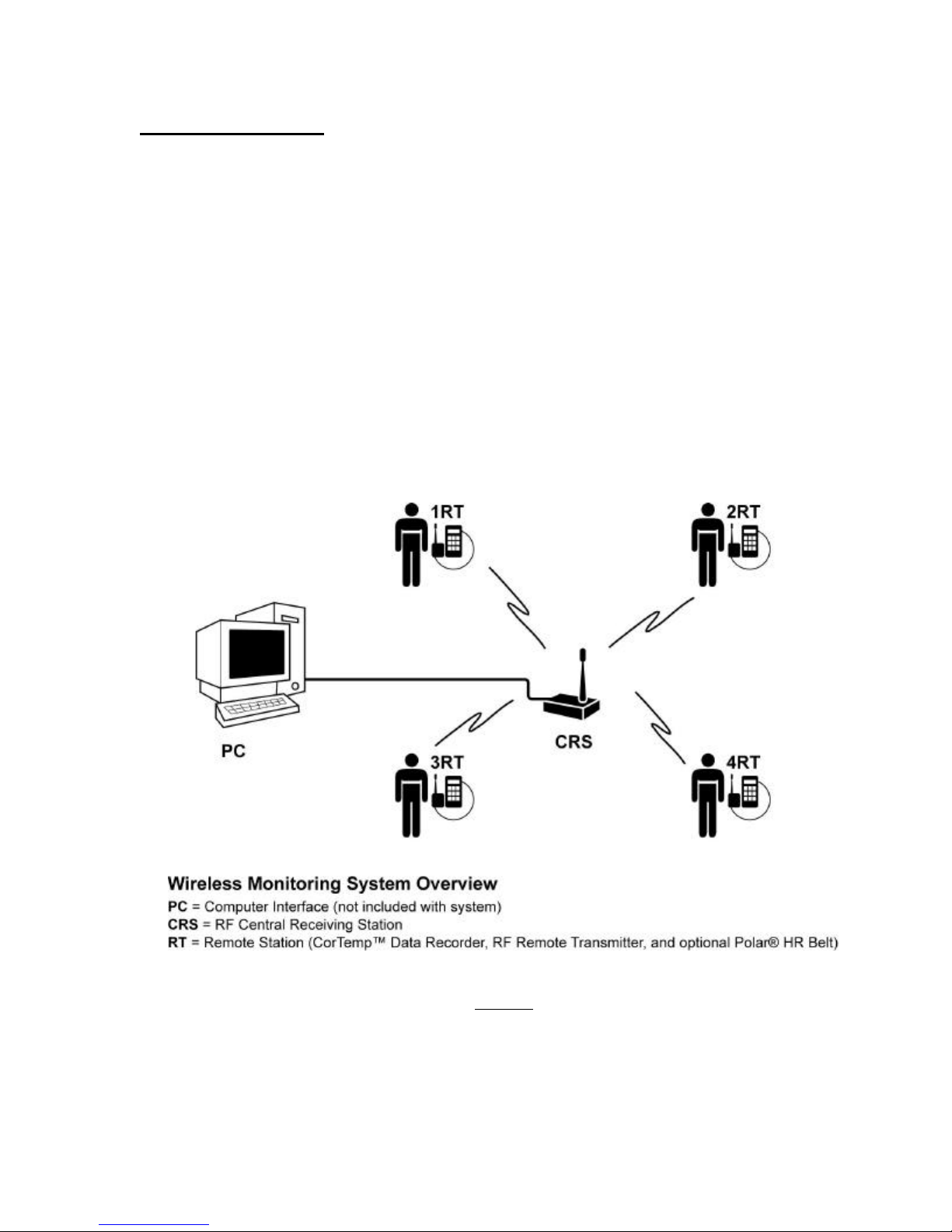
I. System Overview
The CorTemp™ Wireless Monitoring System is designed to remotely monitor the core body
temperature and heart rate of single or multiple subjects in real-time.
The system hardware consists of an RF Central Receiving Base Station and one or more personal
m onitoring sets that include a CorTemp™ Ambulatory Data Recorder, RF Remote Transmitter
and an optional Polar™ Heart Rate Chest Belt which are worn by the subject.
The base station allows 1-20 subjects to move freely within a 200-300 ft. line of sight distance.
Distances will vary depending on the environmental surrounding.
The system is supported by central station software that displays the individual physiological
data of each subject. (See Figure 1.)
Figure 1.

4
II. System Requirements
Table 1. represents the minimal hardware requirements to operate the wireless monitoring
system. Additional CorTemp Data Recorders and RF Remote Transmitter sets (*) may be added
to monitor up to 19 additional subjects. (Also, see Figure 2.)
Component
CorTemp™ 2002 Ambulatory Data Recorder (*)
RF Central Receiving Station
RF Remote Transmitter (*)
Polar Chest Belt (for HR Option only) (*)
PC Interface Cable
External Power Supply Connection
CorTrack™ RF 3.0 Operating Software
Computer (Not Included With System)
Product No.
HT150001
HT500010
HT500009
HT300005
HT300008
HT250005
Table 1.
III. RF System Set -Up
Following are the steps to ensure proper set-up and functionality of the wireless RF system.
Section III should be repeated for each personal monitoring set (*).
III.1 CorTemp – (See Figure 2.)
a. Insert a new battery into the CorTemp™ unit. Always use ONLY Duracell
Coppertop, Energizer or Ultra Life Batteries for optimal performance.
b. Program the CorTemp™ Data Recorder via the Cor Track™ Software,
Version 3.8 or above or manually via the keypad. (Refer to Section III.2 in
the CorTemp™ User’s Manual). NOTE: The serial port option must be
“ON” for the system to function properly (Refer to Section III.2, 2.7 in the
CorTemp™ User’s Manual.) and the collection interval must be set at a
minimum of 20 seconds. (Refer to Section III.2, 2.3)
c. Turn the unit “OFF”.
d. Place the CorTemp Recorder in the carry pouch ensuring that the serial cable
connection on the CorTemp™ Data Recorder is aligned with the cutout in the
pouch for connection to the RF Remote Transmitter, leaving the pouch
“open”.
e. Connect the RF Remote Interface Cable through the pouch cutout to the
CorTemp™ Data Recorder and then to the RF Remote transmitter.

5
f. Make written note of each RF Remote transmitter channel number (located on
the back of the RF Remote unit) as to how it corresponds to its complimentary
CorTemp™ Data Recorder.
g. Repeat section III.1 for each additional CorTemp™ Data Recorder in the
wireless system.
III.2 RF Central Receiving Station – (See Figure 2.)
a. Turn the unit “OFF”.
b. External Power Supply –
a. Plug the external DC power supply to the RF Central Receiving
Station jack.
b. Plug the AC connector into an AC power source.
b. PC Interface Cable –
a. Connect the 9 pin male DB9 connector to the female connector on the
RF Central Receiving Station.
III.3 RF Remote Transmitter – (See Figure 2.)
Each RF Remote Transmitter has a unique channel ID number that is recognized by the
RF Central Receiving Station. To ensure the integrity of the data collection, be sure to
make note of the transmitter channel number as it corresponds to the CorTemp™ Data
Recorder and subject you monitor. The RF Central Receiving Station will not recognize
duplicate channel numbers. If you add personal monitoring sets to your system in the
future, please ensure that you convey your existing channel numbers to HQ, Inc.
customer service so you do not receive duplicate transmitter channel ID numbers. The
transmitter channel ID number is etched on the back of the transmitter case.
a. Diagnostic LED – Turn the LED switch “OFF”.
b. Repeat Section III.3 for each additional RF Transmitter unit in the wireless
system.
III.4 Computer
a. Turn the PC “ON”.
Run the CorTrack Software program.
b. Plug the DB 9-pin PC interface cable female connector to the Com 1 or Com
2 port on the PC.
c. Turn the RF Central Receiving Station “ON”.

6
Figure 2.
III.5 Diagnostic Systems Test
a. Turn the RF Central Receiving Station “ON”.
b. Turn the RF Remote Transmitter LED switch “ON”.
c. Follow “Systems Test” procedure as outlined in the CorTrack™ RF Software
Operating Manual Version 3.0.
d. Turn the RF Remote Transmitter LED switch “OFF”.

7
III.6 CorTemp™/RF Remote Transmitter Placement
a. Turn the CorTemp™ Data Re corder “ON”.
b. Place the CorTemp™ Data Recorder into the “run/stop” mode.
c. Place the Cortemp™ in the neoprene pouch and seal the pouch.
c. Thread the pouch through the subject’s belt loop and position the belt loop on
the middle of the back. (See Figure 3. below)
d. To avoid battery drain, ensure that the RF Remote Transmitter LED is “OFF”.
The “OFF/ON” LED feature is for diagnostic purposes only.
e. Clip the RF Remote Transmitter to a comfortable area on the side of the body.
(See Figure 3. below)
f. Repeat Section III.6 for each additional CorTemp™ Data Recorder in the
wireless system.
Figure 3.

8
IV. RF Remote Transmitter
IV.1 Product Features
a. Receive LED - Illuminates “YELLOW” when unit
is receiving data fro m the RF Central Receiving
Station.
b. Transmit LED - Illuminates “GREEN” when
unit is transmitting data to the RF Central Receiving
Station.
c. RS232 Remote Interface Connection – Connects
RF Remote Transmitter to the CorTemp Data Recorder.
d. LED Off/On Switch - Must be in “ON” position for unit
diagnostic function. Not required to be “ON” for unit to
operate.
e. Antenna – Non-Removable, whip style.
Product No. HT150009
(Figure 4.)
IV.2 Specifications
Input 9 Volt
RS 232 Serial Port 4800 baud rate, one stop bit, no parity, one start bit
Microprocessor 8 bit 10 mHz
RF Transceiver Operating Freq. 914.5 mHz
Transmission Power 0dBm (1mW) Nominal
Receiver Sensitivity 100 dBm at 1 ppm BER
Receiver Image Rejection > 4 dB
Receiver Board Oscillator Leakage < -65 dBm
Power Source Via CorTemp™ Data Recorder
Weight 4 oz.
Dimensions Length 2.5cm, Width 5cm, Height 6.5cm (15cm
with Antenna)
Antenna Type Whip style (Use only Antenna Supplied)

9
V. RF Central Receiving Station
V.1 PC Requirements
10 mg Hard Drive
Pentium III Processor
Minimum Operating System - 600 mHz
One Available RS232 Port
Windows 98, 2000, or XP Operation System
17” Monitor
(1024 x 768 Resolution Recommended)
V.2 Product Features Product No. HT500010 (Figure 5.)
a. External Power Supply Connection – Connects RF Central Receiving
Station to external power source.
b. On/Off – Must be in “ON” position for unit to function.
c. Power LED – Illuminates “RED” when unit is in “ON” position.
d. Receive LED – Illuminates “YELLOW” when unit is receiving data from
RF remote transmitter. (4)
e. Transmit LED – Illuminates “GREEN” when unit is transmitting data to
the RF remote transmitter.
f. PC Connection – Connects RF Central Receiving Station to PC platform.
g. Antenna – Non-Removable, whip style.
V.3 Specifications
RS 232 Serial Port 4800 baud rate, one stop bit, no parity, one start bit
Microprocessor 8 bit 10 mHz
RF Transceiver Operating Freq. 914.5 mHz
Transmission Power 0dBm (1mW) Nominal
Receiver Sensitivity 100 dBm at 1 ppm BER
LED two – green and yellow, switchable
Receiver Image Rejection > 4 dB
Receiver Board Oscillator Leakage < -65 dBm
Operation Range Line of Sight 200-300 Feet Nominal (Depending on
obstacles and/or surroundings such as buildings)
Power Input 9-12 Volt DC, 100 mA
External Power Source 12 Volt Output DC, Input 90-264 VAC,
47-63 Hz, 1.5A
Antenna Type Whip (Use only antenna supplied)
Operating Range Temperature 0 – 40 degrees C
Weight 8 oz.
Dimensions Length - 13.5cm, Width 6.5cm, Height 3cm
(12cm w/antenna)
Antenna Type Whip style (Use Only Antenna Supplied)

10
VI. Limited Warranty
HQ, Inc. will, at no charge, repair or replace, at its option, defective product or component parts
of the CorTemp™ Wireless Temperature/Heart Rate Monitoring System and its ancillary
equipment within ninety (90) days of receipt of product.
VII. Customer Service/Repair
HQ, Inc. Customer Service hours are 8:00am through 5:00pm EST. Please feel free to contact
Customer Service at 941-721-7588, ext. 11 for technical assistance, return authorizations and
additional equipment purchases.
All equipment is repa ired at our main manufacturing facility located in Palmetto, Florida. Prior
to returning the equipment for repair, an RMA number must be obtained from HQ, Inc. customer
service. The RMA number should be referenced both on the outside of the carton and on all
correspondence sent with the shipment. The shipment should be sent back ONLY via prepaid
freight to:
HQ, Inc. Attn: Repair Dept.
210 9th Street Drive West
Palmetto, FL 34221
The repaired unit(s) will be returned back to you prepaid within two -three weeks of receipt.
Invoices will be submitted to your company for any item out of warranty.
 Loading...