

Page 1
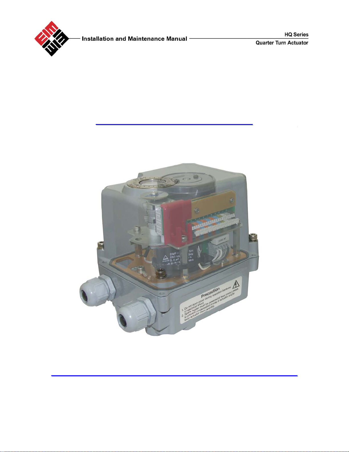
HQ-006 ¼ Turn Actuator
IInnssttaallllaattiioonn && MMaaiinntteennaannccee MMaannuuaall
HQ-006 I&M Manual HQ-402-0606 1
Page 2

Table of Contents
General 1.0
Actuator Mounting 2.0
External Construction 3.0
Standard Wiring Diagrams 4.0
Manual Override 5.0
Electrical Connection
Limit Switch Setting Instructions
Lubrication 8.0
MDPI (Mechanical Dial Position Indicator) ____________________9.0
Maintenance and Storage 10.0
Trouble Shooting 11.0
Standard Specifications 12.0
EIM Office Locations 13.0
1.0 General
HQ series electric actuators are design to provide reliable and efficient operation of 90 degree quarter turn
valves, dampers, etc.
Warning: Use caution when working in, with, or around valves and
actuators. High pressures, forces, voltages and flammable media can be
present
Warning: Failure to follow instructions for proper electrical wiring, storage,
set-up and maintenance may cause serious injury, damage equipment, or
void warranty.
6.0
7.0
HQ-006 I&M Manual HQ-402-0606 2
Page 3
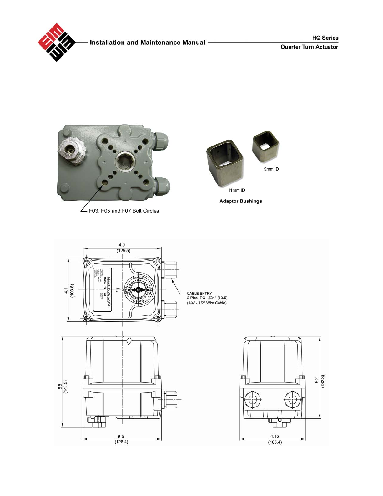
2.0 Actuator Mounting
The actuator may be mounted in any position
The HQ-006 Actuator is supplied with a female output drive and adaptor bushings. ISO5211 FO3/FO5 and
FO7 Bolt patterns are provided for actuator mounting.
3.0 External Construction
HQ-006 I&M Manual HQ-402-0606 3
Page 4
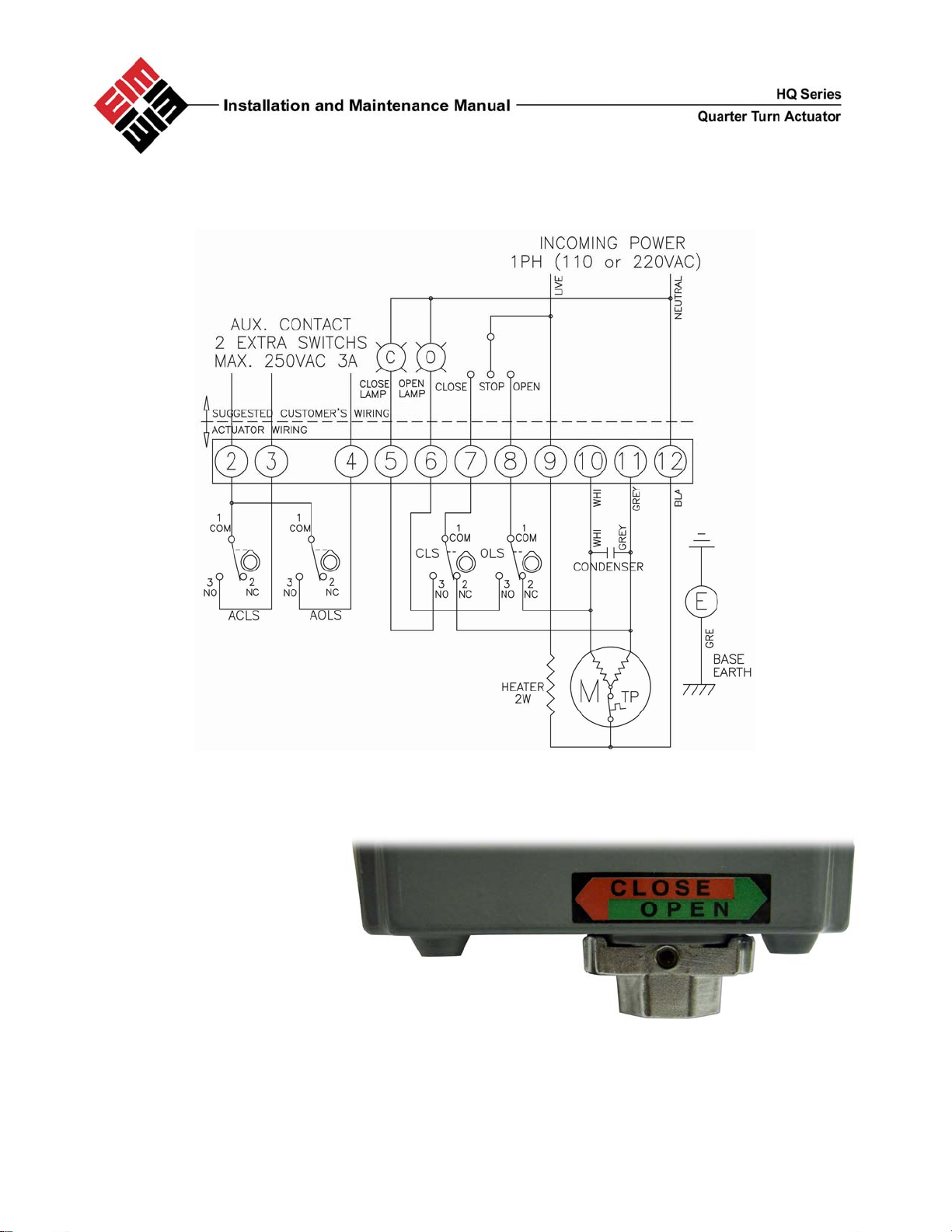
4.0 Standard Wiring Diagram
5.0 Manual Override
The HQ-006 actuator
comes standard with a
manual override nut.
This is located on the
bottom of the unit, and
can be easily operated
with a 5M wrench
.
HQ-006 I&M Manual HQ-402-0606 4
Page 5
6.0 Electrical Connection
Move valve to mid-position by override nut. This will allow sufficient time to stop actuator in case of
improper hook-up
Identify means of removing power during hook-up
Be sure no erroneous remote control signals can be received causing actuator to energize
Electrically operate the valve in the open direction. If the valve closes, actuator must be stopped and
checked for improper field wiring
Set all field conduit entries in accordance with National Electric Code Requirements
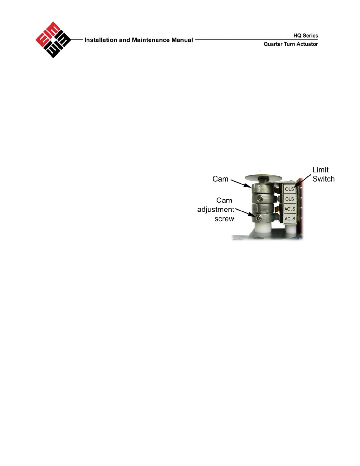
7.0 Limit Switch Setting Instructions
• Operate the actuator manually to closed
position
• Using a hex wrench, loosen the cam adjustment
screw in the CLS limit switch cam
• Rotate the CLS cam towards limit switch lever
until the switch ‘clicks’
• Tighten set screw with hex wrench
• Operated the actuator manually to open position
• Using a hex wrench, loosen the cam adjustment
screw in the OLS limit switch cam
• Rotate the OLS can towards limit switch lever
until the switch ‘clicks’
• Tighten set screw with hex wrench
• Repeat for AOLS and ACLS
8.0 Lubrication
The HQ series actuators are totally enclosed units with a permanently lubricated gear trains (Moly EP
Grease). Once installed lubrication should not be required. However, periodic preventative maintenance
will extend the operating life of the actuator.
9.0 MDPI Settings
Manually rotate actuator to fully closed position
Remove actuator cover
Loosen indicator screw
Adjust indicator to correct orientation
Tighten indicator screw
Replace cover
Check indicator alignment
HQ-006 I&M Manual HQ-402-0606 5
Page 6

10.0 Maintenance and Storage
At least once a year a check should be made of your EIM HQ Series Actuator
Disconnect all power to actuator.
Open Electrical Enclosure. Inspect and tighten all electrical connections
Visually inspect for any electrical or mechanical damage. Replace worn or damaged components.
Check lubrication consistency and levels. Fill or replace if required.
Actuators must be stored in a clean, cool and dry area. The unit shall be stored with the cover installed and the
conduit openings sealed. Storage must be off the floor, covered with a sealed dust protector.
11.0 Trouble Shooting
The following instructions are offered for the most common difficulties encounter during installation and
start-up
Motor will not Run Open in control circuit Refer to appropriate wiring diagram
and check for continuity
Insulation resistance breakdown in motor Perform Megger Test
No power available to actuator Tripped circuit breaker Reset circuit breaker
Manual Override Nut hard to turn Valve stem improperly lubricated Lubricate with grease
Actuator lubrication has broken down Clean out old grease and replace
with recommended lubricant
Valve packing gland too tight Loosen packing gland nuts as
necessary
Jammed valve Refer to valve maintenance
Valve only opens or closes Limit switch improperly set Check setting and reset if necessary
partially with motor
Manual Override Nut will not Stripped gearing Replace as necessary
Operate valve Broken handwheel shaft Replace as necessary
Broken valve stem Repair or replace as necessary
Motor runs but will not operate Stripped gearing Replace as necessary
valve
.
SYMPTOM PROBABLE CAUSE CORRECTIVE ACTION
HQ-006 I&M Manual HQ-402-0606 6
Page 7

12.0 HQ Standard Features
Enclosure Rated Weatherproof IP67
Enclosure High grade aluminium alloy, corrosion co ated
Power Supply 110/220 VAC, 1 PH, 50/60Hz
Motor Reversible Motor
Limit Switches 4 x open/close SPDT, 250VAC 3A rating
Stall Protection Built –in thermal protection
Indicator MDPI (Mechanical Dial Position Indicator)
Manual Override Manual Override Nut
Space Heater 2W Anti-condensation
Conduit Entries (2) x PG13.5
Lubrication Grease moly EP
Ambient Temperature -20 deg C ~ + 70 deg C
External Coating Dry powder polyester
13.0 EIM Office Locations
Head Office and Factory
EIM Controls, Inc.
13840 Pike Road
Missouri City, Texas 77489 USA
(800) 679-1561 toll-free, US Only
(281) 499-1561 phone
(281) 499-8445 fax
EIM Northeastern Regional Office
EIM Southwestern Regional Office
EIM Southeastern Regional Office
EIM Midwestern Regional Office
EIM Western Regional Office
Eastern Hemisphere Sales
EIM Controls UK Ltd.
6-7 Galaxy House
New Greenham Park,
Newbury, Berkshire
RG19 6HW, England
+44 (0) 1635-817-315 phone
+44 (0) 1635-817-460 fax
EIM Controls China
EIM Controls Japan
EIM Controls Italy
EIM Controls Benelux
HQ-006 I&M Manual HQ-402-0606 7
 Loading...