

CorTemp®
HT130003
Data Recorder v4.3
9001 Series
HT130030
HT130042
HT130043
User Manual

CorTemp®
Data Recorder v4.3
9001 Series
HT130003 / HT130042
HT130030 / HT130043
User Manual
Table of Contents
I. Overview ......................................................................................................... 1
II. Accessories and Interfacing Equipment.......................................................... 2
III. CorTemp
A. Programming the Data Recorder – Standard Menu ............................. 4
A.1. Battery Installation ....................................................................... 4
A.2. Using the Keypad – Standard Menu.......................................... 5
A.3. Turning ON the Data Recorder.................................................... 6
A.4. Exit / Standby Mode ..................................................................... 6
Accessing the Standard Programming Menus ...................... 7
Accessing AUTO RUN MODE .............................................. 7
Turning OFF the Data Recorder ........................................... 7
A.5. Date and Time ............................................................................. 7
A.6. Temperature Collection Interval .................................................. 8
A.7. High / Low Temperature Alarms................................................... 8
A.8. Data Transfer............................................................................... 9
A.9. PC LINK....................................................................................... 9
A.10. Temperature Scale ...................................................................... 10
A.11. RF / Real Time Option .................................................................. 10
A.12. Initializing the Data Recorder ...................................................... 11
A.13. Clearing Data............................................................................... 11
A.14. Adding Sensors ........................................................................... 12
A.15. Changing Active Sensor .............................................................. 13
A.16. ID Number ................................................................................... 13
A.17. Sensor Test ................................................................................. 13
A.18. Resetting LBAT ........................................................................... 14
A.19. Low Battery Detector ................................................................... 15
A.20. Signal Detector ............................................................................ 16
A.21. Heart Rate Interval ...................................................................... 16
A.22. High / Low Heart Rate Alarms...................................................... 17
A.23. Sports Mode ................................................................................ 18
A.24. Barcode ....................................................................................... 18
A.25. Time R3.X Option ........................................................................ 19
A.26. Sports Menu Option..................................................................... 20
B. Monitoring Core Body Temperature – Standard Menu ......................... 20
B.1. Administering the Sensor and Checking the Signal .................. 21
B.2. Placement of the Data Recorder ............................................... 21
B.3. Data Collection .......................................................................... 22
B.4. Use of More than One Sensor................................................... 23
B.5. Event Markers in AUTO RUN MODE........................................ 23
B.6. Signal Interference .................................................................... 23
B.7. MEM Message .......................................................................... 24
C. Monitoring Heart Rate – Standard Menu .............................................. 24
D. Downloading Data – Standard Menu .................................................... 24
® Data Recorder – Standard Menu................................................. 4

CorTemp®
Data Recorder v4.3
9001 Series
D.1. Connecting the Data Recorder to a PC / Laptop ........................ 24
D.2. Downloading Data to CorTrack
IV. CorTemp
A. Programming the Data Recorder – Sports Menu.................................. 26
A.1. Battery Installation..................................................................... 26
A.2. Using the Keypad – Sports Menu............................................ 27
A.3. Turning ON the Data Recorder ................................................. 28
A.4. Sports Menu Screen.................................................................. 28
Accessing PC LINK ............................................................... 29
Accessing SPORTS MODE .................................................. 29
Accessing the Sports Programming Menus .......................... 29
Accessing the Standard Programming Menus ...................... 30
Turning OFF the Data Recorder ........................................... 30
A.5. Resetting LBAT ......................................................................... 31
A.6. Sports Menu Option .................................................................. 31
A.7. Adding Sensors ......................................................................... 32
A.8. Sensor Test ............................................................................... 32
B. Monitoring Core Body Temperature – Sports Menu ............................. 33
B.1. Administering the Sensor and Checking the Signal .................. 33
B.2. Placement of the Data Recorder ............................................... 34
B.3. Data Collection .......................................................................... 34
B.4. Use of More than One Sensor................................................... 35
B.5. Signal Interference .................................................................... 35
B.6. MEM Message .......................................................................... 35
C. Monitoring Heart Rate – Sports Menu .................................................. 35
D. Downloading Data – Sports Menu ........................................................ 36
D.1. Connecting the Data Recorder to a PC / Laptop ........................ 36
D.2. Downloading Data to CorTrack
V. Troubleshooting .............................................................................................. 37
® Data Recorder – Sports Menu ..................................................... 26
® II Software.............................. 25
® II Software.............................. 36
HT130003 / HT130042
HT130030 / HT130043
User Manual
VI. Customer Service............................................................................................ 38
Limited Warranty..................................................................................... 38
Service .................................................................................................... 38
Calibration............................................................................................... 38
Appendix 1: Standard Menu Progression .............................................................. 39
Appendix 2: Sports Menu Progression................................................................... 42
Appendix 3: Data Interpretation Key ...................................................................... 43
Appendix 4: Default Parameters ............................................................................ 44
CorTemp®
Data Recorder v4.3
9001 Series
I. Overview
HT130003 / HT130042
HT130030 / HT130043
User Manual
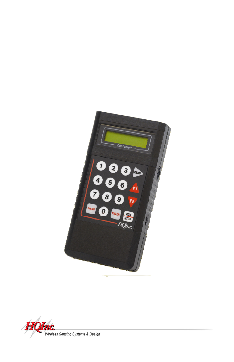
The CorTemp
provides a complete electronic thermometer system that is easy to use and provides
accurate core body temperature measurements (± 0.1°C). The system uses an ingestible,
wireless sensor, which transmits a signal via a near-field magnetic link to the data recorder.
This system has obvious advantages over a "wired probe", for monitoring individuals
performing strenuous activities or working in hazardous environments.
The recorder captures the core body temperature of single or multiple subjects while
participating in sports, working in hazardous conditions, or participating in research
activities in two different modes of monitoring / data collection:
AUTO RUN MODE – CorTemp
while data is collected at user programmable intervals.
SPORTS MODE – CorTemp
individual readings of single or multiple players.
® Data Recorder used in conjunction with a HQI Temperature Sensor
® Data Recorder is worn by the monitored subject
® Data Recorder is held by an athletic trainer taking
1
CorTemp®
Data Recorder v4.3
9001 Series
HT130003 / HT130042
HT130030 / HT130043
II. Accessories and Interfacing Equipment
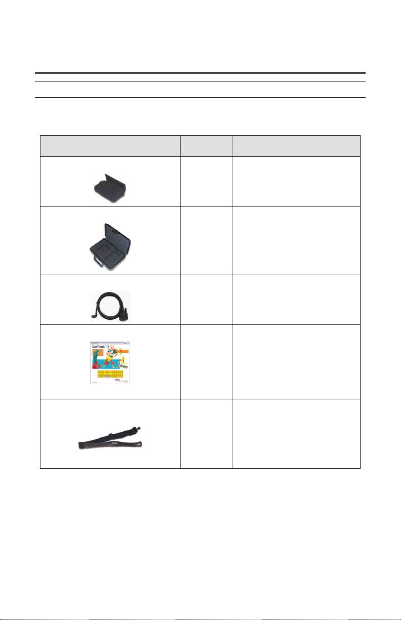
The following accessories may be packaged with your CorTemp
(e.g. HT150001, HT150016, HT150032, or HT150033):
Accessories Part # Description
Data Recorder Pouch
HT300001
Data Recorder Storage Case
HT300002
Data Transfer Cable
HT340004
CorTrack® II Software
via Downloaded file
Polar® T31 (Non-Coded) HR Belt
(Heart Rate Option)
HT300005
® Data Recorder
Soft pouch with belt loop for
wearing Data Recorder.
(AUTO RUN MODE)
Molded plastic carrying case
for Data Recorder.
Allows communication
between the Data Recorder
and a PC / Laptop.
Software interface between
Data Recorder and PC /
Laptop.
Transmits heart rate signal.
User Manual
2
CorTemp®
Data Recorder v4.3
9001 Series
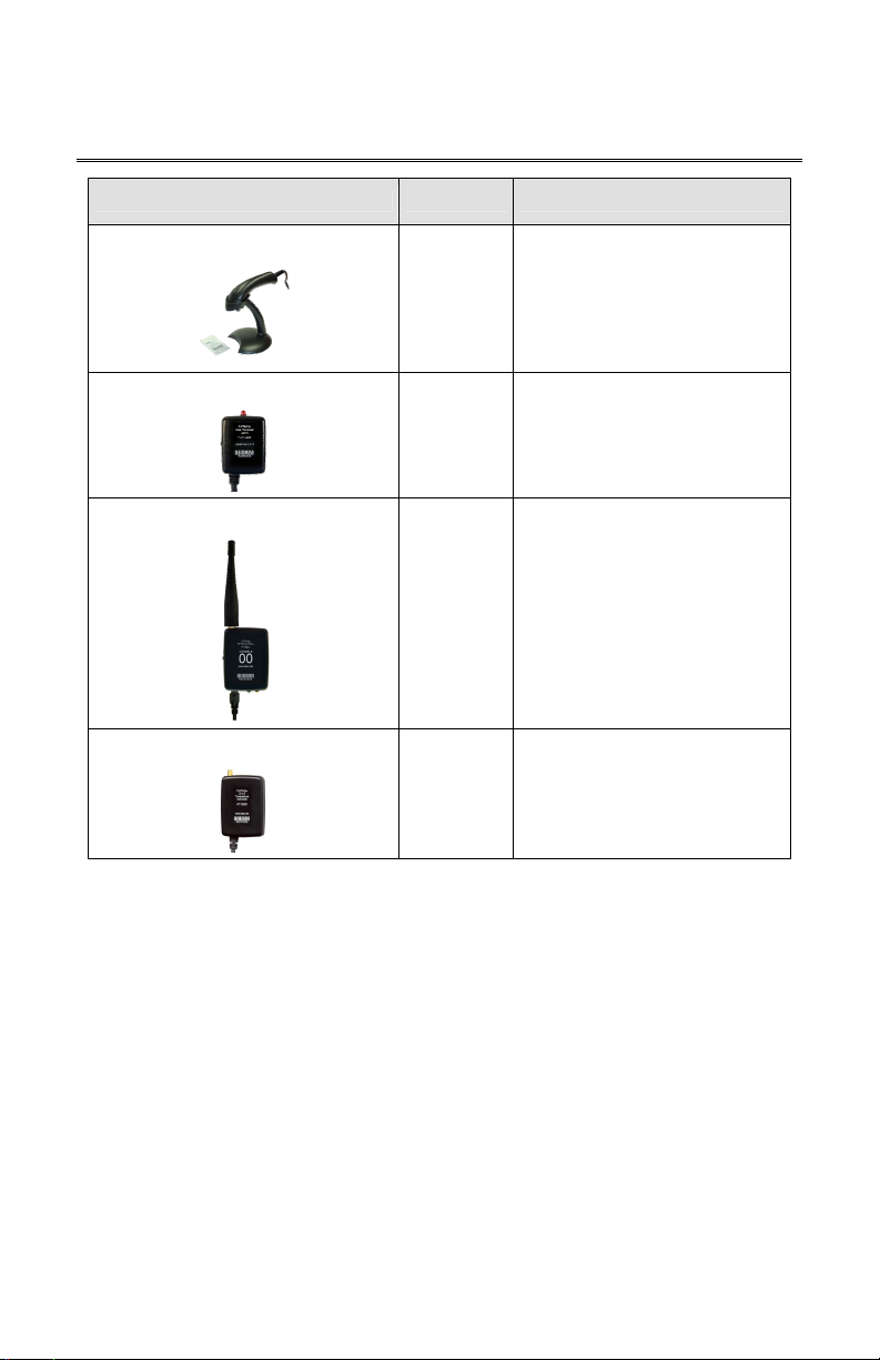
Interfacing Equipment Product # Description
Barcode Scanner System
Data Recorder Alarm
RF Remote Unit
HT130003 / HT130042
HT130030 / HT130043
User Manual
Provides faster input of Serial
& Calibration #s.
HT150025
HT150008
Eliminates data entry errors.
Scans Barcode via LED Beam.
Audio / Visual alarm that can
be positioned on the monitored
subject up to 3ft. from the Data
Recorder.
(AUTO RUN MODE)
D TO A Temperature Converter
HT150009
(914Mhz)
OR
HT150014
(433Mhz)
HT150061
Transmits data via a radio
frequency (RF) to a
RF Central Base Station or a
PDA–RF Base Unit.
Belt clip attachment to subject.
Converts Real Time
temperature output of Data
Recorder to a correlated
voltage for input into analog
devices.
3
CorTemp®
Data Recorder v4.3
9001 Series
HT130003 / HT130042
HT130030 / HT130043
User Manual
III. CorTemp® Data Recorder – Standard Menu
The CorTemp
Temperature Sensor and converts the signal frequency into
digital temperature data. This temperature data is displayed on
the recorder LCD screen with a resolution of 0.01 degree. The
recorder operates within environments between 10 and 50
degrees Celsius. The temperature / heart rate is sampled at
user programmable intervals and displayed for real time
monitoring, while simultaneously saving to memory for future
download and analysis.
The recorder can be programmed as a standalone unit with the
keypad, or it can be programmed by the CorTrack
from your PC / Laptop. The recorder can be programmed with
up to 99 sensor calibration numbers and record / store up to
25,000 readings. The recorder can be used as an ambulatory
unit (AUTO RUN MODE) to collect temperature / heart rate data
for extended periods from one subject, or as a handheld unit
(SPORTS MODE) to collect individual temperature / heart rate
readings from multiple players, easily switching back and forth
between players (active sensors). The data, when
downloaded, displays the active sensor (player) number, the date of the collection period,
and time correlated temperature / heart rate readings.
® Data Recorder receives the signal from the HQI
® II Software
A. Programming the Data Recorder – Standard Menu
A.1. Battery Installation
The recorder operates on a 9V alkaline battery. Energizer
of battery are recommended. The battery will provide approximately 110 hours of
continuous recording at 10 second intervals and can last up to 336 hours (14 days),
depending on the sampling interval.
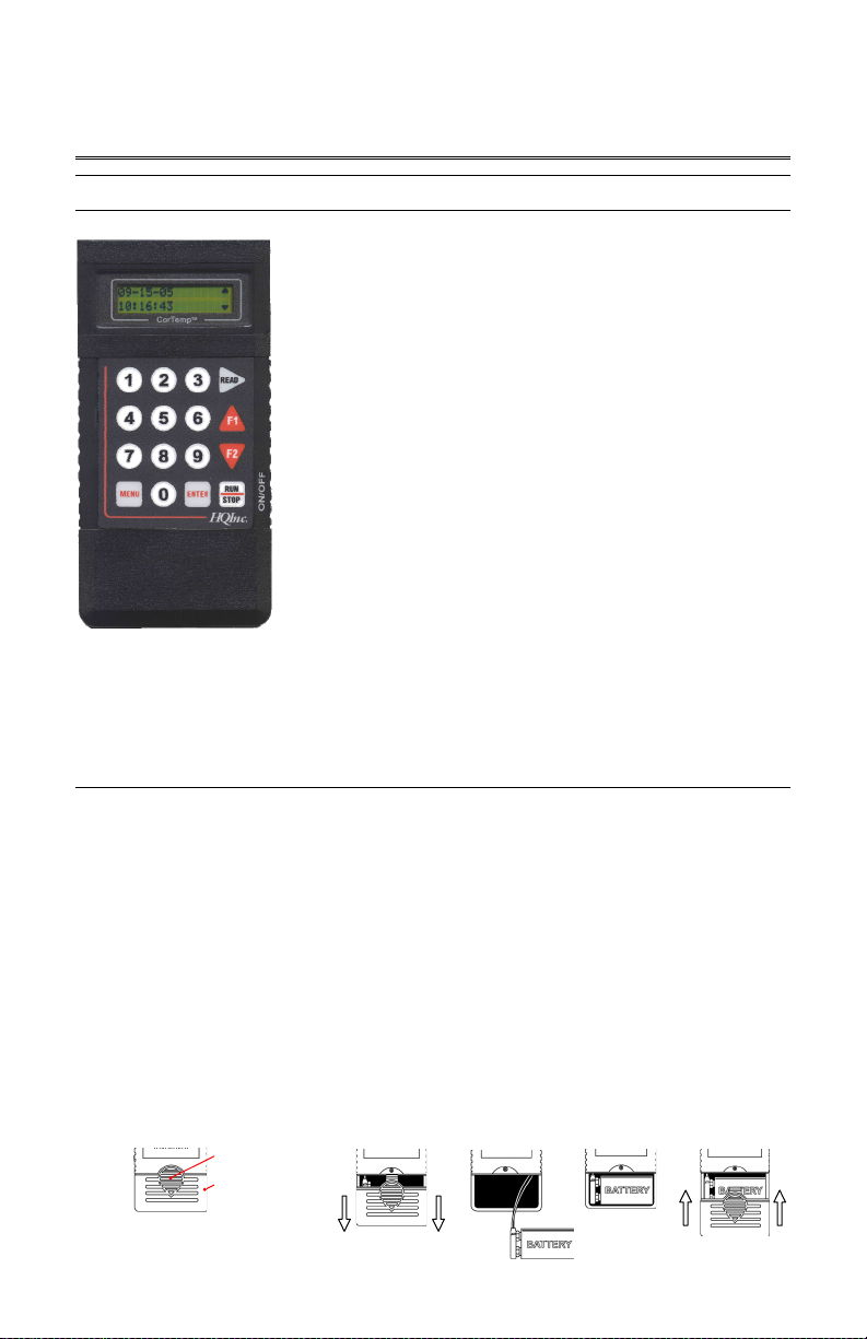
To install the battery in the recorder, do the following:
1. Press down on the battery compartment release button; while pressing down, slide the
battery compartment cover towards the bottom of the detector. (Figure 1)
2. Connect the battery connector to the 9V battery. (Figure 2)
3. Insert the battery into the battery compartment. (Figure 3)
4. Attach the battery cover by aligning the cover with the housing, then slide the cover up
until it latches closed. (Figure 4)
Battery Compartment
Release Button
Battery Compartment
Cover
Back View
4
®
, Duracell®, or Ultralife® brands
Figure 2 Figure 3Figure 1 Figure 4
CorTemp®
Data Recorder v4.3
9001 Series
A.2. Using the Keypad – Standard Menu
HT130003 / HT130042
HT130030 / HT130043
User Manual
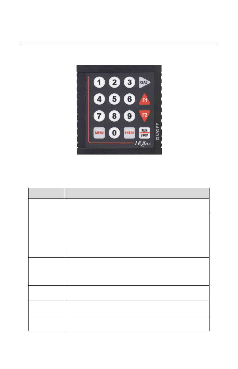
Throughout Section III of this manual, we will refer to specific keys on the keypad. Before
continuing with Section III, take a few moments to observe the keypad and its functions in
relation to the STANDARD MENU.
Key Description
MENU
ENTER
READ
RUN / STOP
F1
F2
0 – 9
From the EXIT / STBY mode, pressing MENU will gain access to
the Standard Programming Menus.
From the Standard Programming Menus, pressing ENTER
returns the recorder to the EXIT / STBY mode.
From the Standard Programming Menus, pressing READ will
move to the next Standard Programming Menu screen. From
the AUTO RUN MODE, pressing READ will take a manual
reading.
From the EXIT / STBY mode, pressing RUN / ST OP begins
AUTO RUN MODE. From AUTO RUN MODE, pressing RUN /
STOP ends AUTO RUN MODE. From PC LINK, pressing RUN /
STOP ends PC LINK.
While in the Standard Programming Menus, pressing F1 selects
the option at the top of the screen.
While in the Standard Programming Menus, pressing F2 selects
the option at the bottom of the screen.
Numeric input for the Standard Programming Menus. From the
AUTO RUN MODE, pressing 0 – 9 will initiate an Event Marker.
5
CorTemp®
Data Recorder v4.3
9001 Series
HT130003 / HT130042
HT130030 / HT130043
User Manual
A.3. Turning ON the Data Recorder
NOTE: If the recorder has been OFF for a week or more, turn the recorder ON for
approximately 10 minutes. This allows the internal components to recharge. After
10 minutes, turn the recorder OFF. Then, after 1 minute, turn the recorder back ON
and initialize the Data Recorder. (Refer to Section III, Part A.12.: Initializing the Data
Recorder).
To turn ON the recorder, do the following:
1. Once the battery has been installed turn the ON / OFF switch to the ON position.
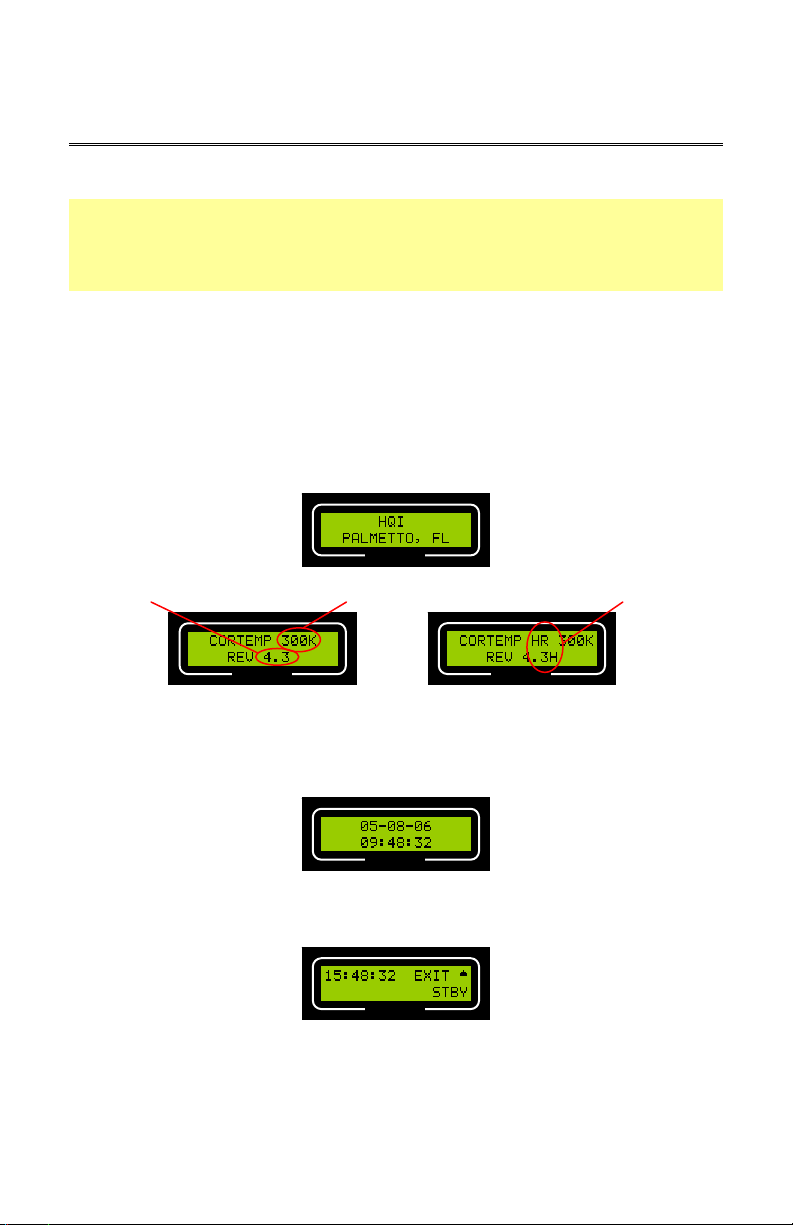
2. The recorder will run a self-test. During the self-test, screens similar to the following
will display. The Firmware Revision #, Heart Rate option, and System Frequency are
noted as below. The system frequency for HT130003 / HT130042 is 262kHz and no
system frequency is displayed on the recorder LCD, while the system frequency for
HT130030 / HT130043 is 300kHz and the system frequency is displayed on the
recorder LCD.
CorTemp®
System Frequency
CorTemp®
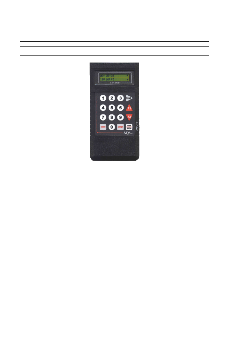
3. On completion of the self-test, the date and time will appear briefly. The date
represents the last programmed date and the time represents the current time. Verify
that the date is not 00-00-00 and that the time is correct.
CorTemp®
Heart Rate DesignationFirmware Revision #
CorTemp®
Heart Rate Recorder Non-Heart Rate Recorder
A.4. Exit / Standby Mode
CorTemp®
EXIT / STBY mode allows the user to access the Standard Programming Menus, initiate
AUTO RUN MODE, and TURN OFF the recorder.
6

CorTemp®
g
g
Data Recorder v4.3
9001 Series
Accessing the Standard Programming Menus
To access the Standard Programming Menus, do the following:
1. From EXIT / STBY mode, press MENU.
2. Press READ to progress through the Standard Programming Menus.
3. Press ENTER on any of the Standard Programming Menus to return to EXIT / STBY
mode.
Accessing AUTO RUN MODE
AUTO RUN MODE allows the user to take Temperature / Heart Rate readings at a set
temperature collection interval.
To initiate AUTO RUN MODE, do the following:
1. From EXIT / STBY mode, press RUN / STOP.
2. Temperature / Heart Rate readings will display at the end of the set interval.
AUTO RUN MODE
To terminate AUTO RUN MODE, press RUN / STOP.
Turning OFF the Data Recorder
To turn OFF the recorder, do the following:
1. From EXIT / STBY mode, press F1.
2. A TURN OFF UNIT message will display.
Temperature Readin
CorTemp® CorTemp®
AUTO RUN MODE
Temperature Readin
HT130003 / HT130042
HT130030 / HT130043
User Manual
with Heart Rate
CorTemp®
3. Turn the recorder ON / OFF switch to the OFF position.
A.5. Date and Time
To program the date and time, do the following:
1. From EXIT / STBY mode, press MENU.
7

CorTemp®
Data Recorder v4.3
9001 Series
2. The DATE / TI ME screen will display.
HT130003 / HT130042
HT130030 / HT130043
User Manual
CorTemp®
3. Press F1 to program the DATE.
4. Enter the Date (mm-dd-yy). NOTE: Default is 00-00-00.
5. Press F2 to program the TIME.
6. Enter the Time (hh:mm:ss). NOTE: Default is 00:00:00. A 24HR format is used,
for example 6:00pm would be entered and displayed as 18:00:00.
7. Press ENTER to return to EXIT / STBY mode.
NOTE: The recorder does not display a changing date, but counts hours and days
from when the date was last entered to keep an accurate elapsed-day record. The
date initially entered will display in the downloaded data as well as all changed dates
with corresponding "H" markers. To display the actual date, simply re-enter the
date. (Refer to Appendix 3: Data Interpretation Key).
A.6. Temperature Collection Interval
The temperature collection interval can be programmed anywhere between every
10 seconds to once every 24 hours (23:59:59). Data is collected at the END of the set
interval. The default interval is 10 seconds. If the heart rate option is to be used, the
required minimum temperature collection interval is 20 seconds.
To program the temperature collection interval, do the following:
1. From EXIT / STBY mode, press MENU.
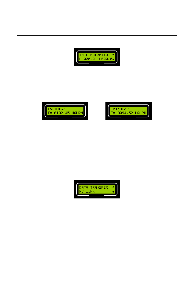
2. Press READ until the INTERVAL / TEMPERATURE ALARM LIMITS screen displays:
CorTemp®
3. Press F1 to program the INTERVAL.
4. Enter the Interval (hh:mm:ss). NOTE: Default is 00:00:10.
5. Press ENTER to return to EXIT / STBY mode.
A.7. High / Low Temperature Alarms
High and Low Temperature Alarms display on the recorder screen when collected data is
outside the programmed parameters. When using a Data Recorder Alarm, this data will
activate an audio / visual alarm, while using the recorder in the AUTO RUN MODE.
To program the high / low temperature alarms, do the following:
1. From EXIT / STBY mode, press MENU.
8
CorTemp®
Data Recorder v4.3
9001 Series
2. Press READ until the INTERVAL / TEMPERATURE ALARM LIMITS screen displays:
HT130003 / HT130042
HT130030 / HT130043
User Manual
CorTemp®
3. Press F2 to program the TEMPERATURE ALARM LIMITS.
4. Enter the High Limit (HL) and the Low Limit (LL). NOTE: Default is 000.0.
5. Press ENTER to return to EXIT / STBY mode.
When the alarm limit is triggered, HALRM (High Limit Alarm) or LALRM (Low Limit Alarm)
will display on the recorder screen.
CorTemp® CorTemp®
Temperature Reading with High Alarm Temperature Reading with Low Alarm
A.8. Data Transfer
DATA TRANSFER allows the user to transfer collected data to terminal programs, such as
HyperTerminal.
To initiate DATA TRANSFER, do the following:
1. From EXIT / STBY mode, press MENU.
2. Press READ until the DATA TRANSFER / PC LINK screen displays.
CorTemp®
3. Press F1 to initiate DATA TRANSFER.
4. Press RUN / STOP to terminate DATA TRANSFER.
5. Press ENTER to return to EXIT / STBY mode.
A.9. PC LINK
PC LINK allows 2-way communication between the recorder and a PC / Laptop. The
CorTrack
To initiate PC LINK, do the following:
1. From EXIT / STBY mode, press MENU.
® II Software uses PC LINK to program the recorder and download data.
9
CorTemp®
Data Recorder v4.3
9001 Series
2. Press READ until the DATA TRANSFER / PC LINK screen displays.
HT130003 / HT130042
HT130030 / HT130043
User Manual
CorTemp®
3. Press F2 to initiate PC LINK.
4. Press RUN / STOP to terminate PC LINK.
5. Press ENTER to return to EXIT / STBY mode.
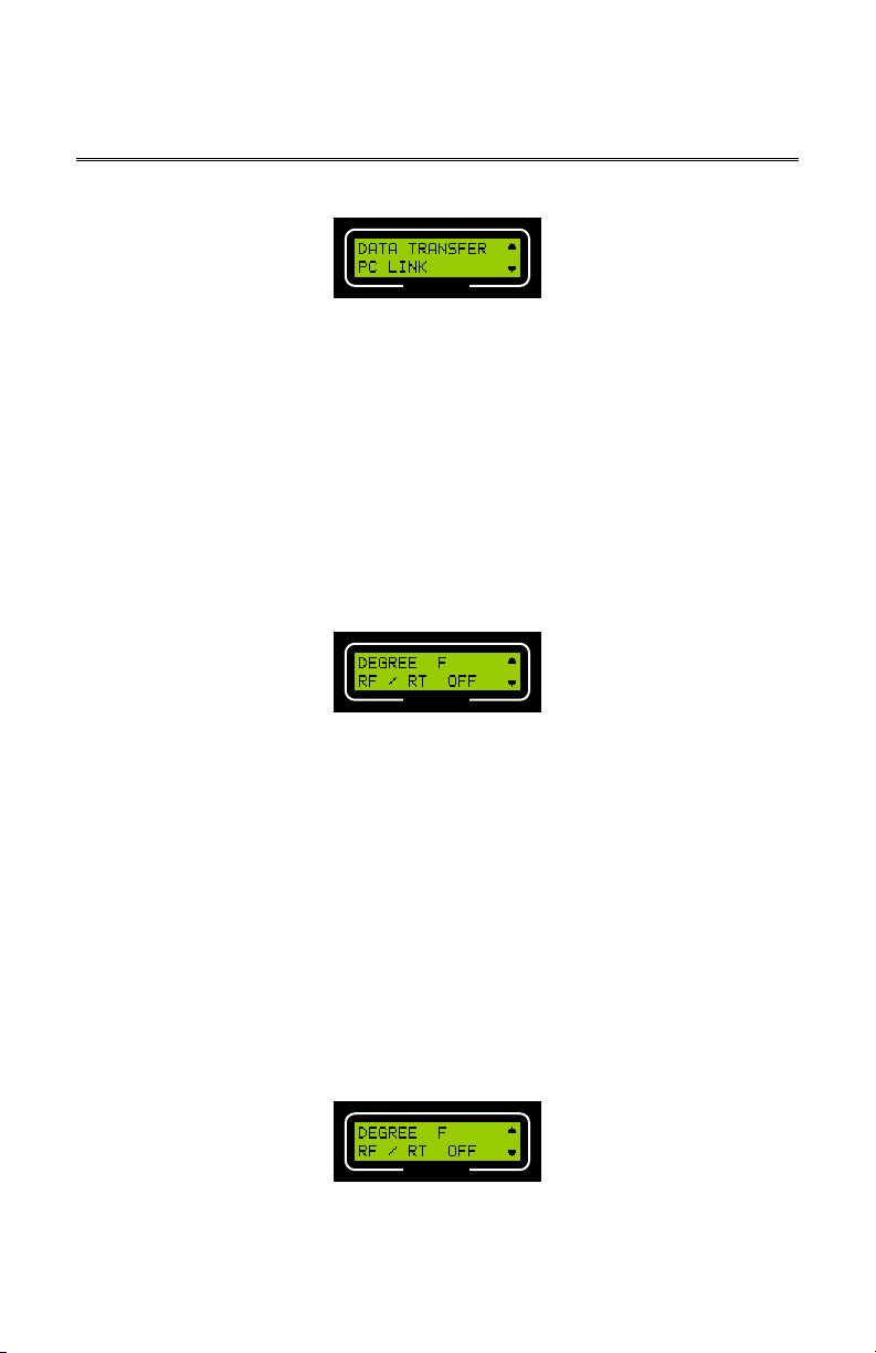
A.10. Temperature Scale
The recorder can be programmed to take temperature readings in either Fahrenheit (F) or
Celsius (C). The default temperature scale is Fahrenheit (F).
To set the temperature scale, do the following:
1. From EXIT / STBY mode, press MENU.
2. Press READ until the DEGREE / RF / RT screen displays.
CorTemp®
3. Press F1 to set the DEGREE status, DEGREE will toggle between F (Fahrenheit) and
C (Celsius). NOTE: Default is F.
4. Press ENTER to return to EXIT / STBY mode.
NOTE: Always Download Data, then Clear Data before switching between
F (Fahrenheit) and C (Celsius).
A.11. RF / Real Time Option
The recorder can transmit via a serial connection to a RF Remote Unit or a PC / Laptop for
Real Time data output. The RF / RT option can be activated for these purposes.
To set the RF / RT status, do the following:
1. From EXIT / STBY mode, press MENU.
2. Press READ until the DEGREE / RF / RT screen displays.
CorTemp®
3. Press F2 to set the RF / RT status, RF / RT will toggle between OFF and ON. NOTE:
Default is OFF.
4. Press ENTER to return to EXIT / STBY mode.
10
CorTemp®
Data Recorder v4.3
9001 Series
HT130003 / HT130042
HT130030 / HT130043
User Manual
A.12. Initializing the Data Recorder
Initializing will clear the recorder memory of all collected temperature / heart rate data, clear
all sensor Serial / Calibration #s, and restore all default parameters. (Refer to Appendix 4:
Default Parameters).
NOTE: Always remember to download any collected data prior to initializing. Any
data not downloaded will be permanently lost.
To initialize the recorder, do the following:
1. From EXIT / STBY mode, press MENU.
2. Press READ until the INITIALIZE / CLEAR DATA screen displays.
CorTemp®
3. Press F1 to INITIALIZE. The following screen will display:
CorTemp®
4. Press F1 to initialize recorder. To cancel, press F2.
5. Press ENTER to return to EXIT / STBY mode.
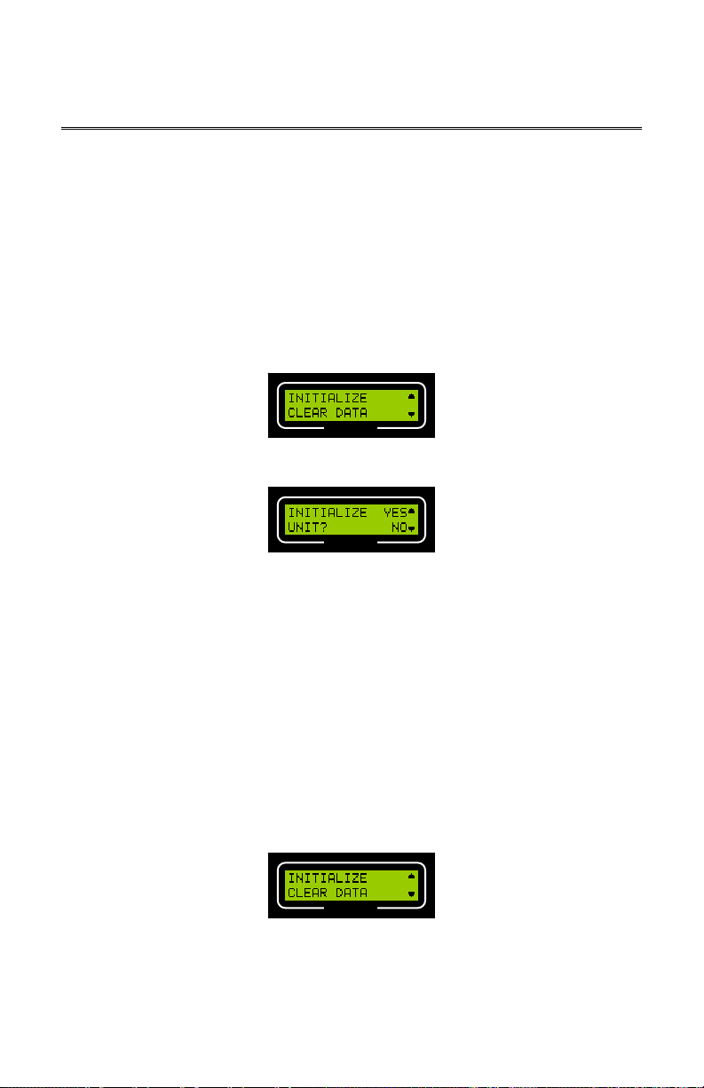
A.13. Clearing Data
Clearing data will clear the recorder memory of all collected temperature / heart rate data.
Clearing data will NOT clear sensor Serial / Calibration #s or programmed parameters.
NOTE: Always remember to download any collected data prior to clearing data. Any
data not downloaded will be permanently lost.
To clear data from the recorder, do the following:
1. From EXIT / STBY mode, press MENU.
2. Press READ until the INITIALIZE / CLEAR DATA screen displays.
CorTemp®
11

CorTemp®
Data Recorder v4.3
9001 Series
3. Press F2 to CLEAR DATA. The following screen will display:
HT130003 / HT130042
HT130030 / HT130043
User Manual
CorTemp®
4. Press F1 to clear data from recorder. To cancel, press F2.
5. Press ENTER to return to EXIT / STBY mode.
A.14. Adding Sensors
To program the recorder with the HQI Temperature Sensors, do the following:
1. From the EXIT / STBY mode, press MENU.
2. Press READ until the ADD SENSOR / SENSOR ACT screen displays.
CorTemp®
3. Press F1 to ADD SENSOR. The following screen will display:
CorTemp®
4. Enter the 2-digit Sensor # (Player #, 01 – 99).
5. When the Sensor # is entered, the following screen will display:
CorTemp®
6. Press F1 to program the Serial #.
7. Enter the 6-digit Serial # from the sensor package label.
8. Press F2 to program the Calibration #.
9. Enter the 8-digit Calibration # from the sensor package label.
10. When the sensor Serial / Calibration #s have been entered, press READ to enter the
Serial / Calibration #s for the next sequential sensor. If no other sensors require
programming, press ENTER to return to the ADD SENSOR / SENSOR ACT screen.
11. Press ENTER to return to EXIT / STBY mode.
Sensor Serial / Calibration #s may be programmed into the recorder via the CorTrack
Software.
NOTE: If any of the calibration numbers have been entered incorrectly, temperature
readings for that sensor will be erroneous. Generally, bad temperature readings will
be so far off as to be immediately obvious. However, there are times when they are
® II
12

CorTemp®
Data Recorder v4.3
9001 Series
not. Attention to detail during data entry is critical to ensure accurate temperature
data collection.
HT130003 / HT130042
HT130030 / HT130043
User Manual
A.15. Changing Active Sensor
The active sensor tells the recorder to assign a specific Calibration # to the sensor signal it
is receiving.
To change the active sensor, do the following:
1. From the EXIT / STBY mode, press MENU.
2. Press READ until the ADD SENSOR / SENSOR ACT screen displays.
CorTemp®
3. Press F2 to program the ACTIVE SENSOR.
4. Enter the 2-digit Sensor # (Player #). NOTE: Default is 01.
5. Press ENTER to return to EXIT / STBY mode.
A.16. ID Number
A 9-digit ID # can be assigned to the collected data. This ID # will appear in the
downloaded data. The recorder unit # can be used as the ID # to identify which recorder
the collected data was downloaded from.
To assign an ID #, do the following:
1. From EXIT / STBY mode, press MENU.
2. Press READ until the ID# / SENSOR TEST screen displays.
CorTemp®
3. Press F1 to program the ID #.
4. Enter the 9-digit ID #. For example, if entering recorder #0521, enter 000000521.
NOTE: Default is 000000000.
5. Press ENTER to return to EXIT / STBY mode.
A.17. Sensor Test
The SENSOR TEST function is used to check for an active sensor signal. The recorder
does not require programming of a sensor calibration # in order to check for an active
signal. The SENSOR TEST feature is system frequency dependent, a recorder with a
262kHz system frequency will only detect a 262kHz temperature sensor or EMI in the
range of 262kHz; other system frequency recorders are the same scenario.
13

CorTemp®
Data Recorder v4.3
9001 Series
SENSOR TEST can be used
to check sensors just received or alarming in storage due to magnet shifting,
to verify that a sensor is active before administering it to a subject (player),
to test whether or not a subject (player) may have passed the sensor from the
body, or
to detect signal interference (EMI), if no sensor is present.
To test a sensor, do the following:
1. From EXIT / STBY mode, press MENU.
2. Press READ until the ID# / SENSOR TEST screen displays.
HT130003 / HT130042
HT130030 / HT130043
User Manual
CorTemp®
3. Press F2 to initiate SENSOR TEST.
4. The recorder will continuously check for an active signal and will display SENSOR ON
or SENSOR OFF, depending on the actual status of the signal.
CorTemp®
5. Press ENTER to return to the ID# / SENSOR TEST screen.
6. Press ENTER to return to EXIT / STBY mode.
CorTemp®
A.18. Resetting LBAT
The LBAT error message will display on the recorder screen when any of the following
situations occur. The recorder has a
low battery,
loses power, or
was turned off incorrectly.
Once detected, the recorder screen will continue to display LBAT until the LBAT is reset.
To reset the LBAT error message, do the following:
1. From EXIT / STBY mode, press MENU.
2. Press READ until the SET BAT / DETECT SIG screen displays.
CorTemp®
14

CorTemp®
Data Recorder v4.3
9001 Series
3. Press F1 to access SET BAT sub-menus. The screen will display LBAT RESET.
HT130003 / HT130042
HT130030 / HT130043
User Manual
CorTemp®
4. Press F1 to reset LBAT. The screen will display BAT OK.
CorTemp®
5. Press ENTER to return to the SET BAT / DETECT SIG screen.
6. Press ENTER to return to EXIT / STBY mode.
A.19. Low Battery Detector
The recorder can be set to detect low battery power and display a LBAT error message.
The recorder will end data collection when it detects low battery power and will go into
sleep mode, which disrupts extended monitoring periods. This feature may not be useful in
all situations. If the battery completely drains, the recorder will shutdown, without losing
data or programmed parameters. It is important not to let the recorder stay in this condition
for an extended period of time. If the internal components discharge completely, data and
parameters will be lost.
To set the recorder to detect low battery power, do the following:
1. From EXIT / STBY mode, press MENU.
2. Press READ until the SET BAT / DETECT SIG screen displays.
CorTemp®
3. Press F1 to access SET BAT sub-menus. The following screen will display:
CorTemp®
4. Press F2 to set the DETECT LBAT status, DETECT LBAT will toggle between ON and
OFF. NOTE: Default is ON.
5. Press ENTER to return to the SET BAT / DETECT SIG screen.
6. Press ENTER to return to EXIT / STBY mode.
15

CorTemp®
Data Recorder v4.3
9001 Series
When the recorder detects low battery power during the EXIT / STBY or AUTO RUN MODE,
the recorder screen will display LBAT. The unit will end data collection and go into sleep
mode.
HT130003 / HT130042
HT130030 / HT130043
User Manual
CorTemp®
A.20. Signal Detector
The recorder can be programmed to display either an obviously incorrect temperature
reading or no temperature reading when the receiver loses the sensor signal while in AUTO
RUN MODE. The Signal Detect feature can be used to eliminate confusion and facilitate
ease of data analysis. (Refer to Appendix 3: Data Interpretation Key)
To set the detect signal feature, do the following:
1. From EXIT / STBY mode, press MENU.
2. Press READ until the SET BAT / DETECT SIG screen displays.
CorTemp®
3. Press F2 to set the DETECT SIG status, DETECT SIG will toggle between ON and
OFF. NOTE: Default is ON.
4. Press ENTER to return to EXIT / STBY mode.
When the DETECT SIG feature is turned ON, the recorder will display T = ---.--, which
records a no-read to memory. The no-read will appear as 8888.88 in the downloaded data.
AUTO RUN MODE SPORTS MODE
CorTemp® CorTemp®
A.21. Heart Rate Interval
If your recorder is equipped with the heart rate option, the recorder will show CORTEMP
HR REV 4.3H, for example, during start up.
Heart Rate Designation
CorTemp®
The heart rate programming screen allows you to select the Heart Rate Interval. The
interval can be set at 1, 2 or 3 beats. The recorder will sample the selected number of
16

CorTemp®
Data Recorder v4.3
9001 Series
beats and extrapolate heart rate per minute based on the time it took to sample the
programmed number of beats. It is recommended that the Heart Rate Interval is set to 3 to
ensure the greatest accuracy.
NOTE: In order to monitor heart rate, the Temperature Collection Interval must be
set at a minimum of 20 seconds.
To program the heart rate interval, do the following:
1. From EXIT / STBY mode, press MENU.
2. Press READ until the H_RATE / HEART RATE ALARM LIMITS screen displays.
HT130003 / HT130042
HT130030 / HT130043
User Manual
CorTemp®
3. Press F1 to program the H_RATE INTERVAL.
4. Enter 0, 1, 2, or 3. NOTE: Default is 0 (OFF).
5. Press ENTER to return to EXIT / STBY mode.
A.22. High / Low Heart Rate Alarms
High and Low Heart Rate Alarms display on the recorder screen when a reading is outside
the programmed parameters. When using a Data Recorder Alarm, this reading will activate
an audio / visual alarm, while using the recorder in the AUTO RUN MODE.
To program high / low heart rate alarms, do the following:
1. From EXIT / STBY mode, press MENU.
2. Press READ until the H_RATE / HEART RATE ALARM LIMITS screen displays.
CorTemp®
3. Press F2 to program the HEART RATE ALARM LIMITS.
4. Enter the High Limit (HL) and the Low Limit (LL). NOTE: Default is 000.0
5. Press ENTER to return to EXIT / STBY mode.
When the alarm limit is triggered, ♥ALRM will display on the recorder screen.
CorTemp® CorTemp®
Heart Rate Reading below Low Limit Temperature & Heart Rate Readings are above
respective High Limits
NOTE: If a temperature HALRM or LALRM is present, the ♥ALRM will NOT
17
display.

CorTemp®
Data Recorder v4.3
9001 Series
HT130003 / HT130042
HT130030 / HT130043
User Manual
A.23. Sports Mode
The SPORTS MODE feature of the recorder allows the athletic trainer to take individual
readings of multiple players by entering the Player # (Player # is the same as the Active
Sensor #).
To initiate SPORTS MODE, do the following:
1. From EXIT / STBY mode, press MENU.
2. Press READ until the SPORTS MODE / BARCODE screen displays.
CorTemp®
3. Press F1 to initiate SPORTS MODE. The following screen will display the most recent
active player # (active sensor #):
CorTemp®
4. Press READ to take a reading for the Player # displayed.
CorTemp® CorTemp®
SPORTS MODE
Temperature Reading
5. To take a reading of a different player, enter the 2-digit Player # (Sensor #).
6. Press RUN / STOP to terminate SPORTS MODE.
7. Press ENTER to return to EXIT / STBY mode.
Temperature Reading with Heart Rate
SPORTS MODE
A.24. Barcode
This feature has been replaced by using the Barcode Scanner System in conjunction with
the CorTrack
The Barco
human errors during sensor data entry into the recorder. This feature is only used with a
SERIAL Barcode Scanner. Sensor Serial / Calibration #s may be programmed into the
recorder via the CorTrack® II software.
® II Software. The system was designed to:
a. Provide faster input of Serial / Calibration #s corresponding to the HQI
Temperature Sensors.
b. Provide accurate input by eliminating the possibility of human errors during
sensor data entry.
de Scanner System provides accurate input by eliminating the possibility of
18

CorTemp®
Data Recorder v4.3
9001 Series
To enter Serial / Calibrations #s using the Barcode Scanner System, do the following:
Connect the Barcode Scanner to the CorTemp® Data Recorder. (Follow the
1.
instructions in the Barcode Scanner System User Manual revision 1.2, Section III,
Part A: Connection to CorTemp® Data Recorder).
After connecting the Barcode Scanner, turn ON the recorder.
2.
From EXIT / STBY mode, press MENU.
3.
Press READ until the SPORTS MODE / BARCODE screen displays.
4.
HT130003 / HT130042
HT130030 / HT130043
User Manual
CorTemp®
Press F2 on the recorder keypad to select BARCODE. The following screen will
5.
display:
CorTemp®
Enter the 2-digit Player # (Sensor #). The following screen will display:
6.
CorTemp®
Scan the barcode on the CorTemp® Core Body Temperature Sensor package label.
7.
When the barcode is scanned, the following screen will display:
8.
CorTemp®
Verify that the Serial / Calibration #s match those on the sensor package label. If the
9.
Serial / Calibration #s are correct, press F1 to select Y (Yes).
If the Serial / Calibration #s are incorrect, press F2 to select N (No). Re-enter the
10.
Player # (Sensor #) and rescan the barcode.
11. When all barcodes have been scanned, press
MODE / BARCODE screen.
ENTER to return to the SPORTS
A.25. Time R3.X Option
The TIME R3.X option allows the recorder, revisions 3.9 and higher, to emulate the time
format used for RF and Real Time transmission of recorders, revisions 3.8 and lower.
To set TIME R3.X status, do the following:
1. From EXIT / STBY mode, press MENU.
19

CorTemp®
Data Recorder v4.3
9001 Series
2. Press READ until the TIME R3.X / SPORTS MENU screen displays.
HT130003 / HT130042
HT130030 / HT130043
User Manual
CorTemp®
3. Press F1 to set TIME R3.X status, TIME R3.X will toggle between OFF and ON.
NOTE: Default is OFF.
4. Press ENTER to return to EXIT / STBY mode.
TIME R3.X OFF supports the CorTrack
higher), and the CorTrack
TIME R3.X ON supports CorTrack
such as HyperTerminal..
® PDA Software (version 2.6 and higher).
® II Software RF / RT module (versions 2.3 and
® II RF Software (version 2.2) and terminal programs,
A.26. Sports Menu Option
The Sports Menu option allows the recorder, revisions 4.3 and higher, to startup in the
SPORTS MENU. The SPORTS MENU allows the athletic trainer to be "one keystroke"
from the two most used options, PC LINK and SPORTS MODE. The SPORTS MENU also
contains a quick link to the following programming menus LBAT RESET, SPORTS MENU,
ADD SENSOR, and SENSOR TEST. Once the Sports Menu option is set to ON, the
recorder will startup in the SPORTS MENU until reset to OFF. For detailed use of this
option (Refer to Section IV: CorTemp
To set SPORTS MENU status, do the following:
1. From EXIT / STBY mode, press MENU.
2. Press READ until the TIME R3.X / SPORTS MENU screen displays.
3. Press F2 to set SPORTS MENU status, SPORTS MENU will toggle between OFF and
ON. (ON returns to SPORTS MENU and OFF returns to STANDARD MENU).
4. Press ENTER after desired selection.
® Data Recorder – Sports Menu).
CorTemp®
B. Monitoring Core Body Temperature – Standard Menu
Once all parameters (DATE, TIME, CALIBRATION #, ACTIVE SENSOR, ETC) have been
programmed, you are now ready to begin monitoring / data collection.
20

CorTemp®
Data Recorder v4.3
9001 Series
HT130003 / HT130042
HT130030 / HT130043
User Manual
B.1. Administering the Sensor and Checking the Signal
Before administering the sensor, be sure to review the Intended Use / Contraindications /
Warnings for the HQI Temperature Sensor. NOTE: The sensor should be administered
at least 4 – 6 hours before monitoring / data collection begins.
To administer the HQI Temperature Sensor, do the following:
1. Remove the magnet from the HQI Temperature Sensor.
2. Verify the sensor has an active signal using the SENSOR TEST function.
3. Remove the sensor Warranty Seal.
4. Give the sensor to the subject (player) as per your organization's protocol
B.2. Placement of the Data Recorder
AUTO RUN MODE – Standard Menu
1. Attach the Data Recorder Pouch to the monitored subject via the belt loop.
2. Place the recorder into the pouch with the recorder keypad facing outward from the
monitored subject and aligning the Data Port down towards the cable relief in the
bottom of the pouch.
NOTE: The recorder will receive the best signal when placed at the small of the
back. When placement at the small of the back is not feasible, the recorder can be
worn near the hip on either side, or on the front at hip level.
21

CorTemp®
Data Recorder v4.3
9001 Series
SPORTS MODE – Standard Menu
HT130003 / HT130042
HT130030 / HT130043
User Manual
Hold the recorder near the small of the back.
NOTE: The recorder will receive the best signal when held at the small of the back.
When placement at the small of the back is not feasible, the recorder can be held
near the hip on either side, or on the front at hip level.
B.3. Data Collection
NOTE: Always Download Data, then Clear Data before:
Switching between F (Fahrenheit) and C (Celsius)
AUTO RUN MODE – Standard Menu
To start monitoring / data collection in AUTO RUN MODE, do the following:
1. From EXIT / STBY mode, press RUN / STOP to initiate AUTO RUN MODE.
2. Place recorder in the Data Recorder Pouch, with the keypad facing outward.
3. To end monitoring / data collection, remove recorder from the pouch and press RUN /
SPORTS MODE – Standard Menu
To start monitoring / data collection in SPORTS MODE, do the following:
1. From EXIT / STBY mode, press MENU.
Changing ID Number (AUTO RUN MODE)
STOP to terminate AUTO RUN MODE.
Manual Readings in AUTO RUN MODE
When in AUTO RUN MODE, press READ. A Temperature / Heart Rate reading will
display. After the recorder screen clears, the recorder will resume the set interval.
NOTE: This reading does record to memory and is noted with an "M".
22

CorTemp®
Data Recorder v4.3
9001 Series
2. Press READ until the SPORTS MODE / BARCODE screen displays.
3. Press F1 to initiate SPORTS MODE.
4. Approach the player (subject) and hold the recorder near the small of the back.
5. Press READ to take a reading for the Player # (Active Sensor #) displayed or enter
the 2-digit Player # (Active Sensor #).
NOTE: Take a minimum of 2 readings per Player # (Active Sensor #) to
ensure correct proximity of the recorder to the Player (Subject) while taking
6. To end monitoring / data collection, press RUN / STOP to terminate SPORTS MODE.
7. Press ENTER to return to EXIT / STBY mode.
NOTE: If erratic readings are observed, verify the following: Placement of the
recorder (AUTO RUN MODE), proximity and movement of the recorder while taking a
reading (SPORTS MODE), and Signal Interference.
a reading.
HT130003 / HT130042
HT130030 / HT130043
User Manual
B.4. Use of More than One Sensor
In some applications it may be necessary to monitor core body temperature even after one
temperature sensor has passed from the body. When using more than one sensor, be
absolutely certain that the previous active sensor has passed from the body.
To verify that a sensor has passed from the body, do the following:
1. Use the SENSOR TEST function to verify that the sensor has passed from the body.
2. Move the recorder to several positions near the abdomen of the subject (player).
3. If the sensor has passed from the body or no longer has an active signal, the screen
will display SENSOR OFF.
NOTE: If two active sensors of the same system frequency are in the subject
(player) at the same time, the resulting temperature recordings will be erroneous.
B.5. Event Markers in AUTO RUN MODE
Each numeric key of the keypad may be correlated to an event. Whenever the subject
(player) experiences a specific event, such as drinking cold liquids or an activity, an event
marker can be tagged to the next collected temperature reading by pressing the
appropriate numeric key. For example, key 1 could be "Cold Drink," key 2 could be
"Running," etc. Each time a key is pressed, the recorder screen will display the event
number entered, and event markers are recorded to memory and appear in the
downloaded data. (Refer to Appendix 3: Data Interpretation Key).
B.6. Signal Interference
Erratic readings may be observed when within close proximity to PC / Laptops, CRTs,
Digital Phone Systems, and other equipment (such as NMR / MRI machines) generating
large electromagnetic fields (EMF).
23

CorTemp®
Data Recorder v4.3
9001 Series
HT130003 / HT130042
HT130030 / HT130043
User Manual
B.7. MEM Message
When the recorder has stored approximately 25,000 readings, it will stop recording data
and the EXIT / STBY mode will display a MEM message. The collected data must be
downloaded to a PC / Laptop for graphing or analysis. Once the data is downloaded, you
may either "Clear Data" or "Initialize Recorder" to reset the MEM message.
C. Monitoring Heart Rate – Standard Menu
If your CorTemp
monitored, use of the POLAR
diagram below for instructions on how to wear the POLAR
NOTE: The Temperature Collection Interval must be set to a minimum of 20 seconds
in order to monitor heart rate.
® Data Recorder includes the heart rate option and heart rate will be
®
T31 (non-coded) Heart Rate Belt is required. Refer to the
1. Attach the transmitter to the chest belt (strap).
2. Adjust the strap length to fit snugly and
comfortably. Secure the strap around your
chest, just below the chest muscles, and
buckle it.
3. Lift the transmitter off your chest and moisten
the two grooved electrode areas on the
back.
4. Check that the wet electrode areas are firmly
against your skin and the Polar logo is in a
central, upright position.
®
Heart Rate Belt:
D. Downloading Data – Standard Menu
D.1. Connecting the Data Recorder to a PC / Laptop
To connect the recorder to a PC / Laptop do the following:
24

CorTemp®
Data Recorder v4.3
9001 Series
1. Plug the MF6 connector of the Data Transfer Cable into the Data Port on the recorder.
Locking Tab
MF6 Connector
Data Port
ON / OFF Switch
HT130003 / HT130042
HT130030 / HT130043
User Manual
2. Connect the DB9 serial connector of the Data Transfer Cable to the appropriate COM
port on the PC / Laptop.
3. Turn ON the recorder.
4. From EXIT / STBY mode, press MENU.
5. Press READ until the DATA TRANSFER / PC LINK screen displays.
6. Press either F2 to initiate PC LINK for communication to the CorTrack
press F1 to initiate DATA TRANSFER to a terminal program.
7. Press RUN / STOP to terminate PC LINK or DATA TRANSFER.
8. Press ENTER to return to EXIT / STBY mode.
9. Unplug the MF6 connector of the Data Transfer Cable from the Data Port on the
recorder. NOTE: When removing the MF6 connector from the Data Recorder,
push and hold the locking tab all the way down while removing the MF6
connector.
® II Software OR
D.2. Downloading Data to CorTrack® II Software
Refer to the CorTrack
® II Software User Manual for downloading instructions.
25

CorTemp®
Data Recorder v4.3
9001 Series
HT130003 / HT130042
HT130030 / HT130043
User Manual
IV. CorTemp® Data Recorder – Sports Menu
The CorTemp
Temperature Sensor and converts the signal frequency into
digital temperature data. This temperature data is displayed on
the recorder LCD screen with a resolution of 0.01 degree. The
recorder operates within environments between 10 and 50
degrees Celsius. The temperature / heart rate is sampled by
the athletic trainer and displayed for real time monitoring, while
simultaneously saving to memory for future download and
analysis.
The recorder is programmed by the CorTrack
your PC / Laptop. The recorder can be programmed with up to
99 sensor calibration numbers and record / store up to 25,000
readings. While in SPORTS MENU, the recorder is used as a
handheld unit (SPORTS MODE) to collect individual
temperature / heart rate readings from multiple players, easily
switching back and forth between players (active sensors). The
data, when downloaded, displays the active sensor (player)
number, the date of the collection period, and time correlated
temperature / heart rate readings. The SPORTS MENU allows
the athletic trainer to be "one keystroke" from the two most used options, PC LINK and
SPORTS MODE. The SPORTS MENU also contains a quick link to the following
programming menus LBAT RESET, SPORTS MENU, ADD SENSOR, and SENSOR TEST.
® Data Recorder receives the signal from the HQI
® II Software from
A. Programming the Data Recorder – Sports Menu
A.1. Battery Installation
The recorder operates on a 9V alkaline battery. Energizer
of battery are recommended. The battery will provide approximately 110 hours of
continuous recording at 10 second intervals and can last up to 336 hours (14 days),
depending on the sampling interval.
To install the battery in the recorder, do the following:
1. Press down on the battery compartment release button; while pressing down, slide the
battery compartment cover towards the bottom of the detector. (Figure 1)
2. Connect the battery connector to the 9V battery. (Figure 2)
3. Insert the battery into the battery compartment. (Figure 3)
4. Attach the battery cover by aligning the cover with the housing, then slide the cover up
until it latches closed. (Figure 4)
Battery Compartment
Release Button
Battery Compartment
Cover
Back View
®
, Duracell®, or Ultralife® brands
Figure 2 Figure 3Figure 1
Figure 4
26

CorTemp®
Data Recorder v4.3
9001 Series
A.2. Using the Keypad – Sports Menu
HT130003 / HT130042
HT130030 / HT130043
User Manual
Throughout Section IV of this manual, we will refer to specific keys on the keypad. Before
continuing with Section IV, take a few moments to observe the keypad and its functions in
relation to the SPORTS MENU.
Key Description
MENU
ENTER
READ
RUN / STOP
F1
F2
0 – 9 Numeric input for Sports Programming Menus.
From the SPORTS MENU, pressing MENU will gain access to
the Sports Programming Menus.
From the Sports Programming Menus, pressing ENTER returns
the recorder to the SPORTS MENU. From the SPORTS MENU,
pressing ENTER will initiate the Exit Routine.
From the Sports Programming Menus, pressing READ will move
to the next Sports Programming Menu screen.
From PC LINK, pressing RUN / STOP ends PC LINK. From
SPORTS MODE, pressing RUN / STOP ends SPORTS MODE.
While in the Sports Programming Menus, pressing F1 selects
the option at the top of the screen.
While in the Sports Programming Menus, pressing F2 selects
the option at the bottom of the screen.
27

CorTemp®
Data Recorder v4.3
9001 Series
HT130003 / HT130042
HT130030 / HT130043
User Manual
A.3. Turning ON the Data Recorder
NOTE: If the recorder has been OFF for a week or more, turn the recorder ON for
approximately 10 minutes. This allows the internal components to recharge. After
10 minutes, turn the recorder OFF. Then, after 1 minute, turn the recorder back ON
and initialize the Data Recorder. (Refer to Section III, Part A.12.: Initializing the Data
Recorder).
To turn ON the recorder, do the following:
1. Once the battery has been installed turn the ON / OFF switch to the ON position.
2. The recorder will run a self-test. During the self-test, screens similar to the following
will display. The Firmware Revision #, Heart Rate option, and System Frequency are
noted as below. The system frequency for HT130003 / HT130042 is 262kHz and no
system frequency is displayed on the recorder LCD, while the system frequency for
HT130030 / HT130043 is 300kHz and the system frequency is displayed on the
recorder LCD.
CorTemp®
System Frequency
CorTemp®
3. On completion of the self-test, the date and time will appear briefly. The date
represents the last programmed date and the time represents the current time. Verify
that the date is not 00-00-00 and that the time is correct.
CorTemp®
Heart Rate DesignationFirmware Revision #
CorTemp®
Heart Rate Recorder Non-Heart Rate Recorder
A.4. Sports Menu Screen
CorTemp®
SPORTS MENU allows the user to access PC LINK and SPORTS MODE, Sports
Programming Menus, TURN OFF the recorder, and view the current time (hh:mm).
28

CorTemp®
Data Recorder v4.3
9001 Series
Accessing PC LINK
PC LINK allows 2-way communication between the recorder and a PC / Laptop. The
CorTrack
To initiate PC LINK, do the following:
1. From SPORTS MENU screen, press F1 to initiate PC LINK. The following will display:
® II Software uses PC LINK to program the recorder and download data.
HT130003 / HT130042
HT130030 / HT130043
User Manual
CorTemp®
2. Press RUN / STOP to terminate PC LINK.
Accessing SPORTS MODE
SPORTS MODE allows the user to take individual readings of multiple players by entering
the Player #.
To initiate SPORTS MODE, do the following:
1. From SPORTS MENU screen, press F2 to initiate SPORTS MODE. The following
screen will display the LAST active Player #:
2. Press READ to take a reading for the Player # displayed:
Temperature Reading
3. To take a reading of a different Player, enter the 2-digit Player #.
To terminate SPORTS MODE, press RUN / STOP.
Accessing the Sports Programming Menus
To access the Sports Programming Menus, do the following:
1. From SPORTS MENU screen, press MENU.
2. Press READ to progress through the Sports Programming Menus.
CorTemp®
CorTemp® CorTemp®
SPORTS MODE
Temperature Reading with Heart Rate
SPORTS MODE
29

CorTemp®
Data Recorder v4.3
9001 Series
3. Press ENTER on any of the Sports Programming Menus to return to SPORTS MENU
screen.
Accessing the Standard Programming Menus
To access the Standard Programming Menus, do the following:
1. From the SPORTS MENU screen, press MENU.
2. The BAT OK / SPORTS MENU screen will display.
HT130003 / HT130042
HT130030 / HT130043
User Manual
CorTemp®
3. Press F2 to toggle OFF the SPORTS MENU, then press ENTER. The recorder will
return to the STANDARD MENU in the EXIT / STBY mode. (Refer to Section III, Part
A: CorTemp
Turning OFF the Data Recorder
To turn OFF the recorder, do the following:
1. From SPORTS MENU screen, press ENTER. The following screen will display:
2. Press F1 to EXIT, or press F2 to CANCEL and return to the SPORTS MENU screen.
3. A TURN OFF UNIT message will display.
4. Turn the recorder ON / OFF switch to the OFF position.
® Data Recorder – Standard Menu)
CorTemp®
CorTemp®
30

CorTemp®
Data Recorder v4.3
9001 Series
A.5. Resetting LBAT
HT130003 / HT130042
HT130030 / HT130043
User Manual
CorTemp®
The LBAT error message will display on the LCD screen when any of the following
situations occur. The recorder has a
low battery
loses power, or
was turned off incorrectly.
Once detected, the recorder screen will continue to display LBAT until the LBAT is reset.
To reset the LBAT error message, do the following:
1. From the SPORTS MENU screen, press MENU. The LBAT RESET / SPORTS MENU
screen will display.
CorTemp®
2. Press F1 to reset LBAT. The screen will display BAT OK.
CorTemp®
3. Press ENTER to return to the SPORTS MENU screen.
A.6. Sports Menu Option
1. From SPORTS MENU screen, press MENU. The BAT OK / SPORTS MENU screen
will display.
CorTemp®
2. Press F2 to set SPORTS MENU status, SPORTS MENU will toggle between OFF and
ON. (ON returns to SPORTS MENU and OFF returns to STANDARD MENU).
3. Press ENTER after desired selection.
31

CorTemp®
Data Recorder v4.3
9001 Series
HT130003 / HT130042
HT130030 / HT130043
A.7. Adding Sensors
To program the recorder with the HQI Temperature Sensors, do the following:
1. From SPORTS MENU screen, press MENU.
2. Press READ until the ADD SENSOR / SENSOR TEST screen displays.
User Manual
CorTemp®
3. Press F1 to ADD SENSOR. The following screen will display:
CorTemp®
4. Enter the 2-digit Player # (Sensor #, 01 – 99).
5. When the Player # (Sensor #) is entered, the following screen will display:
CorTemp®
6. Press F1 to program the Serial #.
7. Enter the 6-digit Serial # from the sensor package label.
8. Press F2 to program the Calibration #.
9. Enter the 8-digit Calibration # from the sensor package label.
10. When the sensor Serial / Calibration #s have been entered, press READ to enter the
Serial / Calibration #s for the next sequential sensor. If no other sensors require
programming, press ENTER to return to the ADD SENSOR / SENSOR ACT screen.
11. Press ENTER to return to the SPORTS MENU screen.
NOTE: If any of the calibration numbers have been entered incorrectly, temperature
readings for that sensor will be erroneous. Generally, bad temperature readings will
be so far off as to be immediately obvious. However, there are times when they are
not. Attention to detail during data entry is critical to ensure accurate temperature
data collection.
A.8. Sensor Test
The SENSOR TEST function is used to check for an active sensor signal. The recorder
does not require programming of a sensor calibration # in order to check for an active
signal. The SENSOR TEST feature is system frequency dependent, a recorder with a
262kHz system frequency will only detect a 262kHz temperature sensor or EMI in the
range of 262kHz; other system frequency recorders are the same scenario.
SENSOR TEST can be used
to check sensors just received or alarming in storage due to magnet shifting,
32

CorTemp®
Data Recorder v4.3
9001 Series
to verify that a sensor is active before administering it to a player (subject),
to test whether or not a player (subject) may have passed the sensor from the
body, or
to detect signal interference (EMI), if no sensor is present.
To test a sensor, do the following:
1. From SPORTS MENU screen, press MENU.
2. Press READ until the ADD SENSOR / SENSOR TEST screen displays.
HT130003 / HT130042
HT130030 / HT130043
User Manual
CorTemp®
3. Press F2 to initiate SENSOR TEST. The recorder will continuously check for an
active signal and will display SENSOR ON or SENSOR OFF, depending on the actual
status of the signal.
CorTemp®
4. Press ENTER to return to the ADD SENSOR / SENSOR TEST screen.
5. Press ENTER to return to the SPORTS MENU screen.
CorTemp®
B. Monitoring Core Body Temperature – Sports Menu
Once all parameters (DATE, TIME, CALIBRATION #, ACTIVE SENSOR, ETC) have been
programmed, you are now ready to begin monitoring / data collection.
B.1. Administering the Sensor and Checking the Signal
Before administering the sensor, be sure to review the Intended Use / Contraindications /
Warnings for the HQI Temperature Sensor. NOTE: The sensor should be administered
at least 4 – 6 hours before monitoring / data collection begins.
To administer the HQI Temperature Sensor, do the following:
1. Remove the magnet from the HQI Temperature Sensor.
2. Verify the sensor has an active signal using the SENSOR TEST function.
3. Remove the sensor Warranty Seal.
4. Give the sensor to the player (subject) as per your organization's protocol.
33

CorTemp®
Data Recorder v4.3
9001 Series
B.2. Placement of the Data Recorder
SPORTS MODE – Sports Menu
HT130003 / HT130042
HT130030 / HT130043
User Manual
Hold the recorder near the small of the back.
NOTE: The recorder will receive the best signal when held at the small of the back.
When placement at the small of the back is not feasible, the recorder can be held
near the hip on either side, or on the front at hip level.
B.3. Data Collection
NOTE: Always Download Data, then Clear Data before switching between
F (Fahrenheit) and C (Celsius)
SPORTS MODE – Sports Menu
To start monitoring / data collection in SPORTS MODE, do the following:
1. From the SPORTS MENU screen, press F2 to initiate SPORTS MODE.
2. Approach the player and hold the recorder near the small of the back.
3. Press READ to take a reading for the Player # (Active Sensor #) displayed or enter
the 2-digit Player # (Active Sensor #).
NOTE: Take a minimum of 2 readings per Player # (Active Sensor #) to
ensure correct proximity of the recorder to the Player (Subject) while taking
a reading.
4. To end monitoring / data collection, press RUN / STOP to terminate SPORTS MODE.
NOTE: If erratic readings are observed, verify the following: Proximity and
movement of the recorder while taking a reading, and Signal Interference.
34

CorTemp®
Data Recorder v4.3
9001 Series
HT130003 / HT130042
HT130030 / HT130043
User Manual
B.4. Use of More than One Sensor
In some applications it may be necessary to monitor core body temperature even after one
temperature sensor has passed from the body. When using more than one sensor, be
absolutely certain that the previous active sensor has passed from the body.
To verify that a sensor has passed from the body, do the following:
1. Use the SENSOR TEST function to verify that the sensor has passed from the body.
2. Move the recorder to several positions near the abdomen of the player (subject).
3. If the sensor has passed from the body or no longer has an active signal, the screen
will display SENSOR OFF.
NOTE: If two active sensors of the same system frequency are in the player
(subject) at the same time, the resulting temperature recordings will be erroneous.
B.5. Signal Interference
Erratic readings may be observed when within close proximity to PC / Laptops, CRTs,
Digital Phone Systems, and other equipment (such as NMR / MRI machines) generating
large electromagnetic fields (EMF).
B.6. MEM Message
When the recorder has stored approximately 25,000 readings, it will stop recording data
and the SPORTS MENU screen will display a MEM message. The collected data must be
downloaded to a PC / Laptop for graphing or analysis. Once the data is downloaded, you
may either "Clear Data" or "Initialize Recorder" to reset the MEM message.
C. Monitoring Heart Rate – Sports Menu
If your CorTemp
monitored, use of the POLAR
diagram below for instructions on how to wear the POLAR
® Data Recorder includes the heart rate option and heart rate will be
®
T31 (non-coded) Heart Rate Belt is required. Refer to the
1. Attach the transmitter to the chest belt (strap).
2. Adjust the strap length to fit snugly and
comfortably. Secure the strap around your
chest, just below the chest muscles, and
buckle it.
3. Lift the transmitter off your chest and moisten
the two grooved electrode areas on the
back.
®
Heart Rate Belt:
35

CorTemp®
Data Recorder v4.3
9001 Series
4. Check that the wet electrode areas are firmly against your skin and the Polar logo is in
a central, upright position.
NOTE: The Temperature Collection Interval must be set at a minimum of 20 seconds
in order to monitor heart rate.
HT130003 / HT130042
HT130030 / HT130043
User Manual
D. Downloading Data – Sports Menu
D.1. Connecting the Data Recorder to a PC / Laptop
To connect the recorder to a PC / Laptop do the following:
1. Plug the MF6 connector of the Data Transfer Cable into the Data Port on the recorder.
Locking Tab
MF6 Connector
ON / OFF Switch
2. Connect the DB9 serial connector of the Data Transfer Cable to the appropriate COM
port on the PC / Laptop.
3. Turn ON the recorder.
4. Press F1 to initiate PC LINK for communication to the CorTrack
5. Press RUN / STOP to terminate PC LINK.
6. Unplug the MF6 connector of the Data Transfer Cable from the Data Port on the
recorder. NOTE: When removing the MF6 connector from the Data Recorder,
push and hold the locking tab all the way down while removing the MF6
connector.
® II Software.
D.2. Downloading Data to CorTrack® II Software
Refer to the CorTrack
® II Software User Manual for downloading instructions.
36

CorTemp®
Data Recorder v4.3
9001 Series
HT130003 / HT130042
HT130030 / HT130043
User Manual
V. Troubleshooting
PROBLEM SOLUTION
1. Reset LBAT message.
2. Replace battery and reset LBAT message.
LBAT message
MEM message 1. Download data, then clear data from recorder.
Temperature readings
No readings
Erratic readings
Consistent readings, but
unreasonable
Heart Rate readings
No readings
Erratic readings
LCD displays incorrect data
format
If your problem persists, please contact HQI Customer Service via email at
customerservice@hqinc.net or call (941) 721-7588, 8:00 am – 5:00 pm EST,
Monday – Friday
3. Check if battery connector has a tight connection and
reset LBAT message.
4. Check if recorder is being turned OFF correctly and
reset LBAT message.
1. Check placement of recorder.
2. Check if subject has expelled the sensor.
1. Check for signal interference (EMI) from rotating
equipment, communication devices, etc..
2. Check if subject has expelled the sensor.
3. Check if multiple sensors of the same system
frequency were administered inadvertently.
1. Check Active Sensor designation.
2. Check if Serial / Calibration #s were entered into
recorder correctly.
1. Check placement of heart rate transmitter.
2. Check if heart rate transmitter is working.
3. Check if heart rate interval is no longer set to "0".
4. Check if recorder has heart rate option.
1. Check for signal interference (EMI) from rotating
equipment, communication devices, etc..
2. Check placement of heart rate transmitter.
3. Check placement of recorder.
1. Check if recorder has been OFF for a week or more. If
so, turn the recorder ON for approximately 10 minutes.
This allows the internal components to recharge. After
10 minutes, turn the recorder OFF. Then, after 1
minute, turn the recorder back ON and initialize the
Data Recorder
37

CorTemp®
Data Recorder v4.3
9001 Series
HT130003 / HT130042
HT130030 / HT130043
User Manual
VI. Customer Service
Limited Warranty
HQ, Inc. will, at no charge, repair or replace, at its option, defective product or component
parts within ninety (90) days from date of purchase.
This warranty does not cover damage resulting from accident, misuse, abuse, water,
tampering, normal wear, service performed or attempted by unauthorized service agencies,
or failure to provide reasonable and necessary maintenance.
IN NO EVENT WILL HQ, INC. BE RESPONSIBLE FOR CONSEQUENTIAL DAMAGES
RESULTING FROM THE USE OF THIS PRODUCT.
Service
To schedule service, please contact HQI Customer Service via email at
customerservice@hqinc.net or call (941) 721-7588, 8:00 am – 5:00 pm EST,
Monday – Friday. An RMA number must be obtained before returning any product for
service. The RMA number must appear on both the outside of the package and on all
correspondence sent with the shipment.
THE SHIPMENT MUST BE SENT, WITH PREPAID FREIGHT, TO:
Service Department
HQ, Inc.
210 – 9th Street Drive West
Palmetto, FL 34221-4802
Calibration
The recorder contains a very accurate quartz crystal oscillator. This oscillator is accurate to
3 parts in 1,000,000. As it ages, it will drift somewhat and could cause your recorder to
give inaccurate temperature readings. For this reason, we suggest you return your
recorder to the factory every 12 months for calibration. There will be a charge for this
calibration service.
Calibration service will also adjust the reception tuning components and perform
functionality testing to ensure your recorder meets factory specifications.
38

CorTemp®
2
)
P
P
g
2
2
P
P
Data Recorder v4.3
9001 Series
HT130003 / HT130042
HT130030 / HT130043
User Manual
Appendix 1: Standard Menu Progression
After turning ON the recorder, the recorder runs a self test and briefly displays the date and
time.
TURN ON
Data Recorder
Press
CorTemp®
Press
RUN / STO
Press
MENU
(Access to Standard
Programming Menus)
CorTemp®
Press
ENTER
(Exit Standard
Programming
Menu
CorTemp®
Press
ENTER
(Exit Standard
Programming
Menu)
CorTemp®
Press
ENTER
(Exit Standard
Programming
Menu)
EXIT / STBY MODE
EXIT:
Shuts down recorder
F1
CorTemp®
CorTemp®
AUTO RUN MODE:
Automatically takes readings for the ac tive sensor
at the end of the temperature collectio n interval
Press
RUN / STO
STANDARD PROGRAMMING MENUS
DATE:
Enter Date
Press
F1
Press
F
Press
READ
(Scrolls through
Standard
Programming
Menus)
Press
F1
Press
F
Press
READ
(Scrolls through
Standard
Programming
Menus)
Press
F1
Press
F
Press
READ
(Scrolls through
Standard
Programming
Menus)
CorTemp®
CorTemp®
TIME:
Enter Time
TEMPERATURE COLLECTION INTERVAL:
Enter Interval
CorTemp®
CorTemp®
HIGH / LOW TEMPERATURE ALARMS:
Enter Hi
h / Low Limits
DATA TRANSFER:
Sends data to
terminal program
CorTemp®
CorTemp®
PC LINK:
2-way communication to CorTrack
for programming recorder & downloading data
RUN / STO
RUN / STO
TURN OFF
Data Recorder
Returns to
EXIT / STBY mode
After entry, returns to
STANDARD
PROGRAMMING
MENU
After entry, returns to
STANDARD
PROGRAMMING
MENU
Press
Press
® II Software
Returns to
STANDARD
PROGRAMMING
MENU
39

CorTemp®
2
2
2
p
p
2
Data Recorder v4.3
9001 Series
CorTemp®
Press
ENTER
(Exit Standard
Programming
Menu)
CorTemp®
Press
ENTER
(Exit Standard
Programming
Menu)
CorTem
Press
ENTER
(Exit Standard
Programming
Menu)
CorTemp®
Press
ENTER
(Exit Standard
Programming
Menu)
®
Press
F1
Press
F
Press
READ
(Scrolls through
Standard
Programming
Menus)
Press
F1
Press
F
Press
READ
(Scrolls through
Standard
Programming
Menus)
Press F1, then
enter sensor #
Press
F
Press
READ
(Scrolls through
Standard
Programming
Menus)
Press
F1
Press
F
Press
READ
(Scrolls through
Standard
Programming
Menus)
TEMPERATURE SCALE:
Toggles DEGREE
F / C
CorTemp®
CorTemp®
RF / RT:
Toggles RF / RT
OFF / ON
INITIALIZE:
YES to Initialize
NO to Cancel
CorTemp®
CorTemp®
CLEAR DATA:
YES to Clear Data
NO to Cancel
ADD SENSOR:
Enter Serial # and
Calibration #
ACTIVE SENSOR:
Enter SENSOR #
ID #:
Enter ID # or
Recorder #
SENSOR TEST:
ON when signal present,
OFF when no signal
CorTem
CorTemp®
CorTemp®
CorTemp®
®
HT130003 / HT130042
HT130030 / HT130043
User Manual
STANDARD PROGRAMMING MENUS (continued, Page 2)
Returns to
STANDARD
PROGRAMMING
MENU
Returns to
STANDARD
PROGRAMMING
MENU
Press
ENTER
Returns to
STANDARD
PROGRAMMING
Returns to
STANDARD
PROGRAMMING
MENU
Press
ENTER
40

CorTemp®
2
2
2
2
p
Data Recorder v4.3
9001 Series
CorTemp®
Press
ENTER
(Exit Standard
Programming
Menu)
CorTemp®
Press
ENTER
(Exit Standard
Programming
Menu)
CorTemp®
Press
ENTER
(Exit Standard
Programming
Menu)
CorTemp®
Press
ENTER
(Exit Standard
Programming
Menu)
ERROR
Press
F1
Press
F
Press
READ
(Scrolls through
Standard
Programming
Menus)
Press
F1
Press
F
Press
READ
(Scrolls through
Standard
Programming
Menus)
Press
F1
Press
F
Press
READ
(Scrolls through
Standard
Programming
Menus)
Press
F1
Press
F
Press
READ
(Scrolls through
Standard
Programming
Menus)
LBAT RESET:
Resets LBAT error
LBAT
CorTemp®
CorTemp®
DETECT LBAT:
Toggles DETECT LBAT
ON / OFF
CorTemp®
DETECT SIGNAL:
Toggles DETECT SIGNAL
ON / OFF
HEART RATE INTERVAL:
Enter Interval
CorTemp®
CorTemp®
HIGH / LOW HEART RATE ALARMS:
Enter High / Low Limits
SPORTS MODE:
Enter Player # to take
readings of multiple players
CorTemp®
CorTemp®
Enter Player #, then SCAN
sensor package label
OR press ENTER to exit
TIME R3.X:
Toggles TIME R3.X
OFF / ON
CorTemp®
CorTemp®
SPORTS MENU:
Toggles SPORTS MENU
OFF / ON
HT130003 / HT130042
HT130030 / HT130043
User Manual
STANDARD PROGRAMMING MENUS (continued, Page 3)
Press F1, then
ress ENTER
Press
ENTER
Returns to
STANDARD
PROGRAMMING
MENU
After entry, returns to
STANDARD
PROGRAMMING
MENU
Press
RUN / STOP
Returns to
STANDARD
PROGRAMMING
Press
MENU
ENTER
BARCODE:
YES to Accept
NO to Reject
Returns to
STANDARD
PROGRAMMING
MENU
Press
ENTER
SPORTS MENU
41

CorTemp®
2
p
p
p
p
p
2
P
)
U
p
p
p
2
play
U
p
2
p
p
P
Data Recorder v4.3
9001 Series
Appendix 2: Sports Menu Progression
After turning ON the CorTemp
displays the date and time.
TURN ON
Data Recorder
CorTem
®
Press
ENTER
(Exit CorTemp®
Data Recorder
CorTem
®
® Data Recorder, the recorder runs a self test and briefly
SPORTS MENU
PC LINK:
2-way communication to CorTrack
Press
F1
Press
F
Press
MENU
(Access to Sports
Programming Menus)
for programming recorder & downloading data
CorTem
®
CorTem
®
SPORTS MODE:
Enter Player # to take
readings of multiple players
Press
RUN / STO
Press
RUN / STO
SPORTS PROGRAMMING MENUS
LBAT RESET:
Resets LBAT error
CorTem
Press
ENTER
(Exit Sports
Programming
Menu)
CorTem
Press
ENTER
(Exit Sports
Programming
Menu)
®
Press
READ
(Scrolls through
Sports Programming
Menus)
®
Press
READ
(Scroll through
Sports Programming
Menus)
LBAT
ERROR
Press
F
Press F1, then
er #
enter
Press
F
CorTem
®
CorTem
®
SPORTS MENU:
Toggles SPORTS MENU
ON / OFF
ADD SENSOR:
Enter Serial # and
Calibration #
CorTem
®
CorTem
SENSOR TEST:
ON when signal present,
OFF when no signal
®
EXIT MENU
EXIT:
Shuts down recorder
Press
F1
Press
Returns to SPORTS MEN
F
CorTem
®
Data Recorder
HT130003 / HT130042
HT130030 / HT130043
User Manual
® II Software
Returns to SPORTS MENU
Press
F1
Resets LBAT error and
returns to SPORTS
PROGRAMMING
MEN
Press
ENTER
STANDARD MENU
Press
ENTER
Returns to
SPORTS
PROGRAMMING
MENU
Press
ENTER
TURN OFF
42

CorTemp®
Data Recorder v4.3
9001 Series
Appendix 3: Data Interpretation Key
Downloaded Data File (.dat) Data Interpretation Key
A
REV 4.0
B
S01, 111111, 11111111
S02, 222222, 22222222
S03, 333333, 33333333
S04, 444444, 44444444
S05, 555555, 55555555
▼
S95, 111111, 33333333
S96, 111111, 33333333
S97, 111111, 33333333
S98, 111111, 33333333
S99, 111111, 33333333
I000000411
E
AT115.0,040.0
F
AR100.0,060.0
G
B00-00:00:00
H
DF,01,10/03/05
H00,08
T48:08,0137.28
N
R48:08,070.7
O
M48:17,0137.31
P
R48:17,064.3
▼
T49:28,0137.33
R49:28,081.5
E49:28,1
Q
▼
T50:08,8888.88
R
R50:08,049.9
DF,01,10/03/05
S
H00,10
T58:15,0045.73
R58:15,080.2
DF,05,10/03/05
T
H00,10
T59:54,0039.12
R59:54,050.3
H02,11
U
T00:14,0039.54
R00:14,051.4
C
I J K
L
M
D
A = Data Recorder Revision #
(4.0 and higher)
B = Sensor # (Player #)
C = Sensor Serial #
D = Sensor Calibration #
E = ID # (Recorder #)
F = High / Low Temperature Alarm
Limits
G = High / Low Heart Rate Alarm
Limits
H = LBAT – Day and Time LBAT
occurred
I = Temperature Scale (DF or DC)
J = Active Sensor # (Player #)
K = Date Marker (mm/dd/yy)
L = Days from Date Marker
M = Hour of Day (24hr format)
N = Temperature Reading
(Minutes:Seconds,Temperature)
O = Heart Rate Reading
(Minutes:Seconds,Heart Rate)
P = Manual Reading
(Minutes:Seconds,Temperature)
Q = Event Marker
(Minutes:Seconds,Key Pressed)
R = No-Read
S = Break in data stream indicates
data collection was interrupted
and then restarted
T = Active Sensor # (Player #) was
changed
U = Time has incremented to the
11th hour of day 2
HT130003 / HT130042
HT130030 / HT130043
User Manual
43

CorTemp®
Data Recorder v4.3
9001 Series
Appendix 4: Default Parameters
CorTemp®
CorTemp®
CorTemp®
CorTemp®
CorTemp®
CorTemp®
CorTemp®
CorTemp®
CorTemp®
00-00-00
00:00:00
00:00:10
000.0, 000.0
F
OFF
01
000000000
ON
ON
0 (OFF)
000.0, 000.0
OFF
OFF (Initial Startup)
HT130003 / HT130042
HT130030 / HT130043
User Manual
44

www.hqinc.net
HQ, Inc.
210 – 9th Street Drive West
Palmetto, FL 34221-4802 USA
PL1033 Rev 0
HT130003 / HT130030 / HT130042 / HT130043 User Manual Printed in USA
 Loading...