

Page 1

HP StorageWorks
External Storage XP user guide
for the XP12000, XP10000, SVS200
Part number: T1706-96009
Eighth edition: September 2007
Page 2

Legal and notice information
© Copyright 1999, 2007 Hewlett-Packard Development Company, L.P.
Confidential computer software. Valid license from HP required for possession, use or copying. Consistent with FAR 12.211 and
12.212, Commercial Computer Software, Computer Software Documentation, and Technical Data for Commercial Items are licensed
to the U.S. Government under vendor's standard commercial license.
The information contained herein is subject to change without notice. The only warranties for HP products and services are set forth
in the express warranty statements accompanying such products and services. Nothing herein should be construed as constituting
an additional warranty. HP shall not be liable for technical or editorial errors or omissions contained herein.
Microsoft, Windows, Windows XP, and Windows NT are U.S. registered trademarks of Microsoft Corporation.
Page 3

Contents
Aboutthisguide .......................... 11
Supported storage platforms and firmware............................ 11
Intendedaudience...................................... 11
Prerequisites ........................................ 11
Relateddocumentation.................................... 11
Documentconventionsandsymbols ............................. 12
HPtechnicalsupport.................................... 12
Subscriptionservice .................................... 13
HPwebsites ....................................... 13
Documentationfeedback.................................. 13
1Overviewofconnectingexternalarrays................ 15
ExternalStorageXPfeatures................................. 15
2PreparingforExternalStorageXPoperations ............. 17
Systemrequirements .................................... 17
Storagearraysthatcanbeconnectedasexternalarrays................... 17
ExternalStorageXPrequirements............................... 21
InstallingExternalStorageXP ................................ 21
PreparingforExternalStorageXPsettings........................... 21
Externalports..................................... 22
External LU to be mapped . . . . . . . . . . . . . . . . . . . . . . . . . . . . . . . . 22
ExternalLUgroups................................... 22
ExternalLUattributessetbymapping........................... 22
Alternatepaths .................................... 24
Example of an alternate path configuration ...................... 24
ExamplesofswitchingI/Oexecutionpathstoalternatepaths............... 26
Poweringarraysonoroff.................................. 30
Poweringlocalarraysonoroff ............................. 31
Topowerlocalarraysoff.............................. 31
Topowerlocalarrayson .............................. 32
Poweringexternalarraysonoroff ............................ 32
Topowerexternalarraysoff............................. 32
Topowerexternalarrayson............................. 32
TurningOnorOffPowerSupplyofBothlocalandexternalarrays............... 33
UsingmappedexternalLUsfromthehostconnectedtothelocalarray............... 34
WritingnewdatatomappedexternalLUs......................... 34
Using existing data in mapped external LUs . . . . . . . . . . . . . . . . . . . . . . . . 35
UninstallingExternalStorageXP............................... 36
LimitationsonExternalStorageXPoperations ......................... 37
CombiningExternalStorageXPwithotherHPStorageWorksproducts............... 42
UsingexternalLUsforAutoLUNXPoperations....................... 44
UsingexternalLUsforContinuousAccessXPoperations................... 45
UsingexternalLUsforContinuousAccessXPJournaloperations................ 46
UsingexternalLUsforBusinessCopyXPoperations..................... 48
UsingexternalLUsforSnapshotXPoperations....................... 48
3Managingcachewithexternalstorage................ 51
Guidelinesforusingcachewithexternalstorage........................ 51
External Storage XP user guide
3
Page 4

Determining,setting,orchangingtheexternalLUcachemode .................. 52
Determiningifthecachemodeisdisabled ........................ 52
Changingthecachemode ............................... 52
Collectingdeviceinformation ............................ 53
DeletingandremappingtheexternalLU........................ 55
Partitioningcacheforexternalstorage ............................ 55
Forexample,CompanyAuses: ............................. 56
Inanotherexample,CompanyBusesthefollowingstoragetiers: ............... 56
Topartitioncacheforexternalstorage: .......................... 56
Determiningthenumberandsizeofneededpartitions ..................... 56
Creatingcachepartitions.................................. 57
Changingstoragesystemmodes............................... 59
4ExternalStorageXPpanes ..................... 61
LUOperationpane .................................... 61
Devicetree...................................... 63
Devicelist ...................................... 64
WWNtree...................................... 66
WWNlist ...................................... 67
Porttree ....................................... 69
Portlist........................................ 70
Filterbutton...................................... 72
Presetlist(LUOperationpane).............................. 72
PortOperationpane.................................... 73
PortOperationtree................................... 74
PortOperationlist................................... 75
Presetlist(PortOperationpane) ............................. 76
5ConfiguringexternalLUs..................... 77
Overview of configuringexternalLUs............................. 77
Settinganexternalarray'sport ............................... 78
Settingalocalarray'sportattributes ............................. 78
DiscoveringandMappingLUs................................ 79
MappingexternalLUsindividually(AddLU) ........................ 79
SelectPathspane ................................. 83
MappingmultipleexternalLUsat(AddLU(Auto))...................... 88
SelectLDEVwindow................................ 91
DisplayingdetailedinformationstoredinVMA(VMAinformation) .............. 93
SettingalternatepathsforexternalLUs ............................ 95
Definingalternatepaths ................................ 98
Changing a definedalternatepathpriority ........................ 98
Canceling alternate path definitions ........................... 100
Changingalternatepaths................................ 100
Replacing All the Alternate Paths with Newly-added Alternate Paths . . . . . . . . . . . . . . 100
AddingalternatepathsbyselectingmultipleexternalLUs(AddPaths) ............... 102
DeletingalternatepathsbyselectingmultipleexternalLUs(DeletePaths).............. 104
CheckinganexternalLU'sstatus(LDEVInformation)....................... 105
ObtaininginformationaboutexternalLUs......................... 105
RestoringexternalLUs(Restore) ............................. 107
Displaying configurationinformationforexternalLUs(VolumeDetail) ............. 108
DisconnectingexternalarraysorLUs ............................. 109
DisconnectingallexternalLUsinanexternalarray(DisconnectSubsystem)........... 110
DisconnectingexternalLUsindividually(DisconnectVolume) ................. 111
Checking the connection status and resuming external LU operations (Check Paths & Restore Vol.) . . . 112
RestoringallexternalLUsinanexternalarray(CheckPaths&RestoreVol.)........... 112
RestoringexternalLUsindividually(CheckPaths&RestoreVol.)................ 113
RestoringexternalLUs(LDEVRestore)............................. 113
Restoringvolumesinanexternalarray .......................... 113
RestoringvolumesinamappedexternalLUindividually................... 114
4
Page 5

ChangingthecachemodesettingoftheexternalLU ...................... 114
ChangingthecachemodeofallexternalLUsinanexternalarray................. 114
ChangingthecachemodeofanindividualexternalLU ..................... 115
Stopping the use of paths to an external LU by specifying an external array's WWN (Disconnect Paths) . 115
Restoring paths to an external LU by specifying an external array's WWN (Check Paths) . . . . . . . 116
Changinganexternalarray'sportsetting........................... 116
Stopping the use of paths to an external LU by specifying a local array's port (Disconnect Paths) . . . . 118
RestoringpathstoanexternalLUbyspecifyingalocalarray'sport(CheckPaths) .......... 118
DeletingexternalLUmappings(DeleteLU)........................... 118
6 Troubleshooting NAS Blade systems that include external arrays . . . . 121
Stoppingandrestartingexternalarrays............................ 121
Stoppingexternalarrays ................................ 122
RestartingexternalarraysandrestoringNASBladesystems ................. 122
Recoveryproceduresforerrorsinexternalarrays........................ 123
Errorsinanexternalarray'sdisk............................. 123
Errorsinapathtotheexternalarray ........................... 125
Errorsinallpathstotheexternalarray .......................... 127
Ifeachnodeusesadifferentexternalarray ...................... 127
Ifbothnodesusethesameexternalarray....................... 128
7Remotecommanddevices .................... 131
Overviewofremotecommanddevices ............................ 131
Noticesaboutremotecommanddevices ........................... 131
Mappingcommanddevicesasremotecommanddevices .................... 133
Using Continuous Access XP or Continuous Access XP Journal with remote command devices . . . . . 134
UsingInitiator/ExternalMIXmode ............................ 135
RestrictionsonInitiator/ExternalMIXmode ........................ 136
8TroubleshootingExternalStorageXP................ 137
ANotesonconnectingexternalarrays................ 143
ConnectingThunder9500Vsubsystems............................ 143
SystemparametersforconnectingThunder9500Vsubsystems ................ 143
Relation btw. ser. nums. in the Dev. list on LU Op. pane & Thunder 9500V subsys. mod. . . . . . 145
Relationship between the WWN of the port on the Thunder 9500V subsystem and the controller . 145
Pathstatusandexamplesofrecoveryprocedures(Thunder9500Vsubsystems) ......... 146
ConnectingTagmaStoreAMSandTagmaStoreWMSsubsystems................. 147
System parameters for connecting TagmaStore AMS and TagmaStore WMS subsystems . . . . . 147
Rel. btw. ser. numbs. in Dev. list on the LU Op. pane & T-Stor. AMS & T-Stor. WMS subsys. mods. 150
Relation btw. the WWN of the port on the TagmaStore AMS or TagmaStore WMS subsys. and contr. 150
Path status and examples of rec. proce. (TagmaStore AMS and TagmaStore WMS subsys.) . . . . 151
ConnectingXP12000/XP10000DiskArrays.......................... 152
Path status and examples of recovery procedures (XP12000/XP10000 Disk Arrays) . . . . . . . 152
ConnectingXP1024/XP128DiskArrays............................ 153
Pathstatusandexamplesofrecoveryprocedures(XP1024/XP128DiskArrays) ......... 154
ConnectingXP512/XP48DiskArrays............................. 154
Pathstatusandexamplesofrecoveryprocedures(XP512/XP48DiskArrays) .......... 155
ConnectingHP200StorageVirtualizationSystemasexternalstorage............... 155
Pathstatusandexamplesofrecoveryprocedures(SVS200) ................. 156
ConnectingEVAarrays................................... 157
IdentifyinglogicalvolumesofEVAarrays(usingCharacteristic2)............... 157
Alternatepath'sbehaviorwhenanEVAarrayisconnected.................. 157
BRequiredvolumecapacityforemulationtypes............ 159
External Storage XP user guide
5
Page 6

CAdjustingvolumecapacityforcopypairsetting ........... 165
Copyingdatafromexternalarrays(usingexternalLUsasP-VOLs)................. 165
Copyingdatatoexternalarrays(settingexternalLUsasS-VOLs) ................. 166
DConfi guringMSA1000/1500asexternalarrays........... 167
ConfiguringexternalarrayLUs,hostmode,andports...................... 167
ConnectingMSA1000/1500 ................................ 167
SettinguptheMSA .................................... 168
DefiningMSAarrayobjects................................. 168
Calculating MSA LU size and definingLUs........................... 169
SelectiveStoragePresentation................................ 169
Index .............................. 171
6
Page 7

Figures
1
2
3
4
5
6
7
8
9
10
11
12
13
14
15
16
17
18
19
20
21
22
23
24
25
26
27
28 ..LUOperationpane............................... 62
29
30
31
32
33 ..Porttree ................................... 69
34
35
36
37 ..PortOperationpane.............................. 73
..ExternalStorageXPconcept........................... 16
..Example of alternate path configuration...................... 25
..Example of alternate path configurationusingtwoswitches.............. 25
..Example of incorrect alternate path configurations ................. 26
..AlternatepathmodeisMultimode........................ 27
..AlternatepathmodeisSinglemode ....................... 28
..Alternate path mode is Single mode with alternate paths in Normal and Standby . . . . 29
..AlternatepathmodeisSinglemodewithalternatepathsinStandbyonly........ 30
..WritingnewdatatomappedexternalLUs..................... 35
..UsingexistingdatainmappedexternalLUs(withoutformatting)............ 36
..ExampleofexternalLUwith2TBorless...................... 37
..Ext. LU cap. is larger than the spec. emulation type's basic cap. (OPEN-3 ex.) . . . . . 38
..External LU capacity is smaller than the specified emulation type's basic capacity . . . . 38
..ExampleofAutoLUNXPoperations ....................... 44
..Example
..ExampleofContinuousAccessXPJournaloperations ................ 47
..ExampleofBusinessCopyoperations....................... 48
..ExampleofSnapshotXPoperations........................ 49
..LU Ope
..LUOperationpane,LUnumberandUUID..................... 53
..LUOperationpane,PathSettingoption...................... 54
..PathSettingpane ............................... 54
..LDEVInformationpane............................. 55
..Partition Definitionpane ............................ 57
..Partition Definitionpane,Cutoption ....................... 58
..Partition Definitionpane,PasteParityGroupoption................. 59
..PanesforExternalStorageXPoperations ..................... 61
..Devicetree .................................. 63
..Devicelist(externaldeviceselectedinDevicetree) ................. 64
..WW
..WWNlist(ExternalDevicesselectedintheWWNtree)............... 67
..Portlist(ExternalselectedinPorttree)....................... 70
..Filterwindow ................................. 72
..PresetDetailwindow(mappingoperation)..................... 73
ofContinuousAccessXPoperations ................... 46
rationpane,CacheModesetting ..................... 52
Ntree.................................. 66
External Storage XP user guide
7
Page 8

38
..PortOperationtree............................... 74
39
..PortOperationlist ............................... 75
40
..Preset Deta
41
..Overview of configuringexternalLUs....................... 77
42
..AddLUwindow................................ 80
43
..SelectPathspane ............................... 84
44
..Add LU pane
45
..AddLUpane(mappingwiththeLinearbuttonreleased ............... 86
46
..SSIDwindow ................................. 87
47
..SetSSIDwindow ............................... 87
48
..AutoMapSettingwindow............................ 89
49
..SelectLDEVwindow .............................. 91
50
..VMAInformationpane............................. 94
51
..PathSettingwindow .............................. 96
52
..PathSettingwindow,shortcutmenu........................ 99
53
..Overview of Operation to Replace All the Current Alternate Paths with Newly-added Alternate
ilwindow(changingportattribute)................... 76
(mappingusingtheLinearbutton) .................. 86
Paths ..................................... 101
54
..AddPathswindow............................... 102
55
..DeletePathswindow.............................. 104
56
..LDEV In
57
..ShortcutmenuoftheLDEVInformationwindow................... 108
58
..VolumeDetailwindow ............................. 109
59
..Disconnect Subsystem and Check Paths & Restore Vol. Commands . . . . . . . . . . 111
60
..ChangeParameterpane ............................ 117
61
..Example of a NAS Blade system configuration that includes an external array . . . . . . 122
62
..Errorinanexternalarray'sdisk ......................... 124
63
..Errorinapathtotheexternalarray........................ 126
64
..Erroroccursonthepathtotheexternalarrayusedfornode1 ............ 127
65
..Ifbothnodesusethesameexternalarray ..................... 129
66
..Overviewofremotecommanddevice....................... 131
67
..DifferencebetweenStandardandInitiator/ExternalMIXmodes............ 134
68
..Us
69
..Configuration example for which logical volumes can only be identified by characteristic . 157
formationwindow............................ 106
ing Continuous Access XP or Continuous Access XP Journal with remote command devices 135
70 ..LDEVcapacity................................. 160
71
..CalculatingLUcapacity(OPEN-3example) .................... 160
72
..Copyingdatafromexternalarrays(usingexternalLUsasP-VOLs)........... 166
73
..Copyingdatatoexternalarrays(settingexternalLUsasS-VOLs) ........... 166
74
..Example:ConnectinganMSAarray ....................... 168
75
..DefiningMSAarrayobjectswiththeACU..................... 169
76
..DefiningMSALUswithACU........................... 169
77
..ConfiguringSSPwithACU ........................... 170
8
Page 9

Tables
1
2
3
4
5
6
7
8
9
10
11
12
13
14
15
16
17
18
19
20
21
22
23
24
25
26
27
..Documentconventions ............................. 12
..Storagearraysthatcanbeconnectedasexternalarrays............... 18
..ExternalStorageXPrequirements......................... 21
..WhenexternalLU'semulationtypeisOPEN.................... 41
..WhenexternalLU'semulationtypeisformainframes ................ 41
..Recommended individual CLPR cache size for external storage on open systems . . . . . 56
..Recommend
..Externalarraystatusvalues ........................... 65
..MappedexternalLUstatusvalues ........................ 65
..Information displayed in the Device column for remote command devices . . . . . . . . 132
..Restrictionsonremotecommanddevices ..................... 133
..GeneralExternalStorageXPtroubleshooting.................... 137
..Systemparametersettings(Thunder9500Vsubsystems) ............... 144
..Relationship between serial numbers and subsystem models (Thunder 9500V subsystems) . 145
..Relati
..Path status and examples of recovery procedures (Thunder 9500V subsystems) . . . . . 147
..System parameter settings (TagmaStore AMS and TagmaStore WMS subsystems) . . . . 149
..Relation btw. ser. numbs. & subs. mods. (TagmaStore AMS & TagmaStore WMS subs.) . 150
ionbtw.ports'WWNs&contrs.(TagmaStoreAMS&TagmaStoreWMSsubs.) . . 150
..Relat
..Pathstat.&ex.ofrec.proced.(TagmaStoreAMS&TagmaStoreWMSsubs.) . . . . . 151
..Path status and examples of recovery procedures (XP12000/XP10000 Disk Arrays) . . . 153
..Path status and examples of recovery procedures (XP1024/XP128 Disk Arrays) . . . . . 154
status and examples of recovery procedures (XP512/XP48 Disk Arrays) . . . . . . 155
..Path
..Pathstatusandexamplesofrecoveryprocedures(SVS200) ............. 156
..ExternalLU'smaximumusablecapacity...................... 159
..LDEVcapacityinformationforeachemulationtype................. 161
umecapacityinformationforeachemulationtype ................ 162
..Vol
edindiv.CLPRcachesizeforext.stor.onHPstor.virt.sys. ........ 57
onship between ports' WWNs and controllers (Thunder 9500V subsystems) . . . . 146
External Storage XP user guide
9
Page 10

10
Page 11

About this guide
This guide provides information about:
• Preparing for External Storage XP operations
• Performing External Storage XP operations
• Troubleshooting NAS Blade systems that include external arrays
• Troubleshooting External Storage XP
• Connecting external arrays
• Using an XP12000/XP10000/SVS200 with EVA3000/50000
• ConfiguringMSA1000/1500DiskArraysasexternalarrays
Supported storage platforms and firmware
Unless otherwise specified, the term array in this guide refers to the following supported storage platforms:
• HP StorageWorks XP12000 Disk Array
• HP StorageW
• HP StorageWorks 200 Storage Virtualization System
For supported firmware versions, see HP StorageWorks XP Remote Web Console user guide for
XP12000/XP10000/SVS200.
orks XP10000 Disk Array
Intended audience
This guide is intended for storage network administrators with knowledge of:
• Disk array hardware and software
• Data processing and RAID storage subsystems and their basic functions
Prerequi
sites
Prerequi
• Installing the HP StorageWorks disk array(s)
• Installing the license key for this product
sites for using this product include:
Related documentation
The following documents provide related information:
• HP StorageWorks XP glossary
• HP StorageWorks XP Remote Web Console user guide for XP12000/XP10000/SVS200
• HP StorageWorks Auto LUN XP user guide for the XP12000/XP10000/SVS200
• HP StorageWorks Business Copy XP user guide for the XP12000/XP10000/SVS200
• HP StorageWorks Cache LUN XP user guide for XP12000/XP10000/SVS200
• HP StorageWorks Continuous Access XP Journal user guide
• HP StorageWorks Continuous Access XP user guide for the XP12000/XP10000/SVS200
• HP StorageWorks Flex Copy XP user guide
External Storage XP user guide
11
Page 12
• HP StorageWorks LUN Configuration and Security Manager XP user guide for
XP12000/XP10000/SVS200
• HP Array Configuration Utility User Guide (for HP StorageWorks Modular Smart Arrays)
You can find these documents on the HP manuals web site:
ttp://www.hp.com/support/manuals.
h
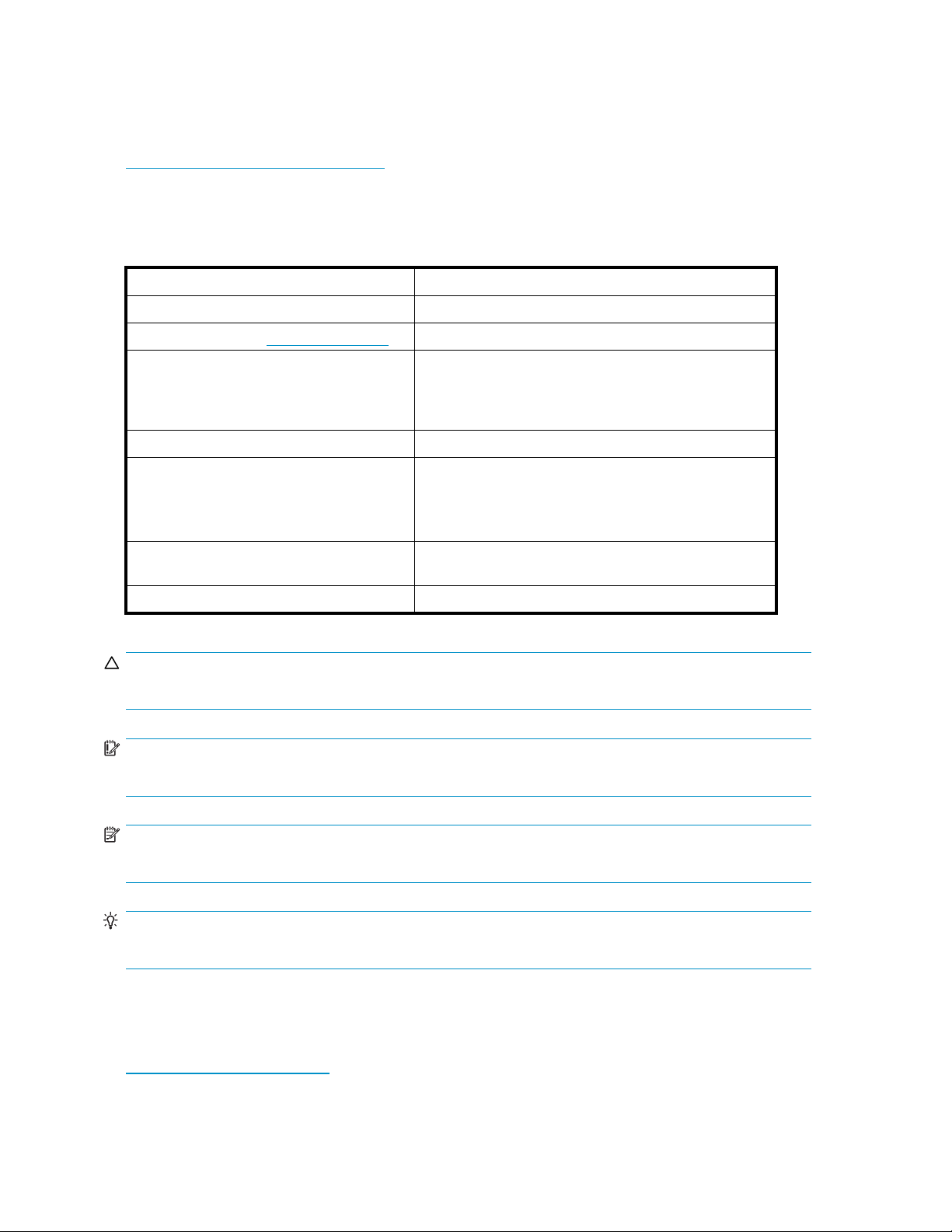
Document conventions and symbols
Table 1 Docume
Convention
Blue text: Table 1
Blue, underlined text: http://www.hp.com
Bold text
Italic text Text emphasis
Monospace text
Monospace, italic text
Monospace, bold text
nt conventions
Element
Cross-reference links and e-mail addresses
Web site addresses
• Keys that are pressed
• Text typed into a GUI element, such as a box
• GUI elements that are clicked or selected, such as
menu and list items, buttons, tabs, and check boxes
• File and directory names
• System output
• Code
• Commands, their arguments, and argument values
• Code variables
• Command variables
Emphasized monospace text
CAUTION:
Indicates that failure to follow directions could result in damage to equipment or data.
IMPORTANT:
Provides clarifying information or specific instructions.
NOTE:
Provides additional information.
TIP:
Provides helpful hints and shortcuts.
HP technical support
Telephone numbers for worldwide technical support are listed on the HP support web site:
ttp://www.hp.com/support/.
h
Collect the following information before calling:
12
About this guide
Page 13

• Technical support registration number (if applicable)
• Product serial numbers
• Product model names and numbers
• Error messages
• Operating system type and revision level
• Detailed questions
For continuous quality improvement, calls may be recorded or monitored.
Subscription
HP recommends
h
ttp://www.
After regist
firmware upda
service
that you register your product at the Subscriber's Choice for Business web site:
hp.com/go/e-updates.
ering, you will receive e-mail notification of product enhancements, new driver versions,
tes, and other product resources.
HP web sites
For additional information, see the following HP web sites:
•h
ttp://www.hp.com
•http://www.hp.com/go/storage
•http://www.hp.com/service_locator
•http://www.docs.hp.com
Documentation feedback
HP welcomes your feedback.
To make com
storagedo
ments and suggestions about product documentation, please send a message to
cs.feedback@hp.com. All submissions become the property of HP.
External Storage XP user guide
13
Page 14

14
About this guide
Page 15

1Overviewofconnectingexternal
arrays
External Storage XP realizes the virtualization of storage arrays. You can use External Storage XP to
access multiple storage arrays connected by a Fibre Channel interface as if they were all one storage
array. Once you connect another storage array to an XP array or storage virtualization system using
External Storage XP, you can also use Command View XP or XP Remote Web Console to manage the
data space (but not necessarily the management) of the other storage arrays.
External Storage XP supports external storage LDEVs of any standard XP emulation type, such as OPEN-3,
OPEN-8, OPEN-9, OPEN-L, OPEN-K, OPEN-V, 3390-3, or 3390-0.
NOTE:
Currently only the HP StorageWorks XP12000 and XP10000 Disk Arrays and the HP StorageWorks 200
Storage Virtualization System (SVS200) support external storage.
In this user guide, the original XP12000/XP10000/SVS200 is called the local array and the connected
storage array is called the external array. The volume managed in the local array is called an internal
storage virtualizer LDEV (or internal LDEV), and the volume in an external array is called an external LU.
IMPORTANT:
This guide contains information about internal disks or LDEVs. Unlike the XP12000/XP10000 Disk
Arrays, the SVS200 has no internal disks. Therefore, information about internal disks or LDEVs does not
apply to the SVS200.
With the help of host mirroring middleware, Auto LUN XP or HP StorageWorks XP Tiered Storage
Manager, you can use External Storage XP for online or offline data migration, providing a point-in-time
copy of data between an external device and the local array.
Flex Copy
array an
HP StorageWorks Flex Copy XP user guide.
XP is another HP StorageWorks product that copies user data between an LU on a local
d an LU on an external storage device. For a detailed description of Flex Copy XP, see the
External Storage XP features
ThefollowingareExternalStorageXPfeatures:
• Using External Storage XP to map an external LU as an internal LDEV, you can manage the
external LU capacity using Command View XP or XP Remote Web Console as if it were a
volume in the local array.
Mapping means assigning Virtual Devices (VDEVs) and, consequently, Logical Devices (LDEVs) and
host port LUs to external LUs. If you map external LUs as internal VDEVs, you can use Command View
XP or XP Remote Web Console to then assign the VDEV to an internal CU:LDEV and a port/LU
address. This allows you to use an external LU as if it were an LDEV in the local array.
External Storage XP user guide
15
Page 16
NOTE:
The phrases
mapped as an internal LU
and
mapped as an internal LDEV
should be interpreted to
mean that the external LU is specifically mapped into the local array as a unique VDEV (Virtual
Device), which is then associated with a local array CU:LDEV (Control Unit:Logical Device), which is
then typically associated with a unique host port/LU combination. Since a local array LU number
is only unique within the name space of a host port (for example, CL1-A), references to “XP LU”
should be interpreted as references to either the unique port/LUN combination or the unique
CU:LDEV combination.
• If you use Flex Copy XP with External Storage XP, you can copy data in the external array to the
local array and copy data in the local array to the external array. For more information about
Flex Copy XP, see the HP StorageWorks Flex Copy XP user guide.
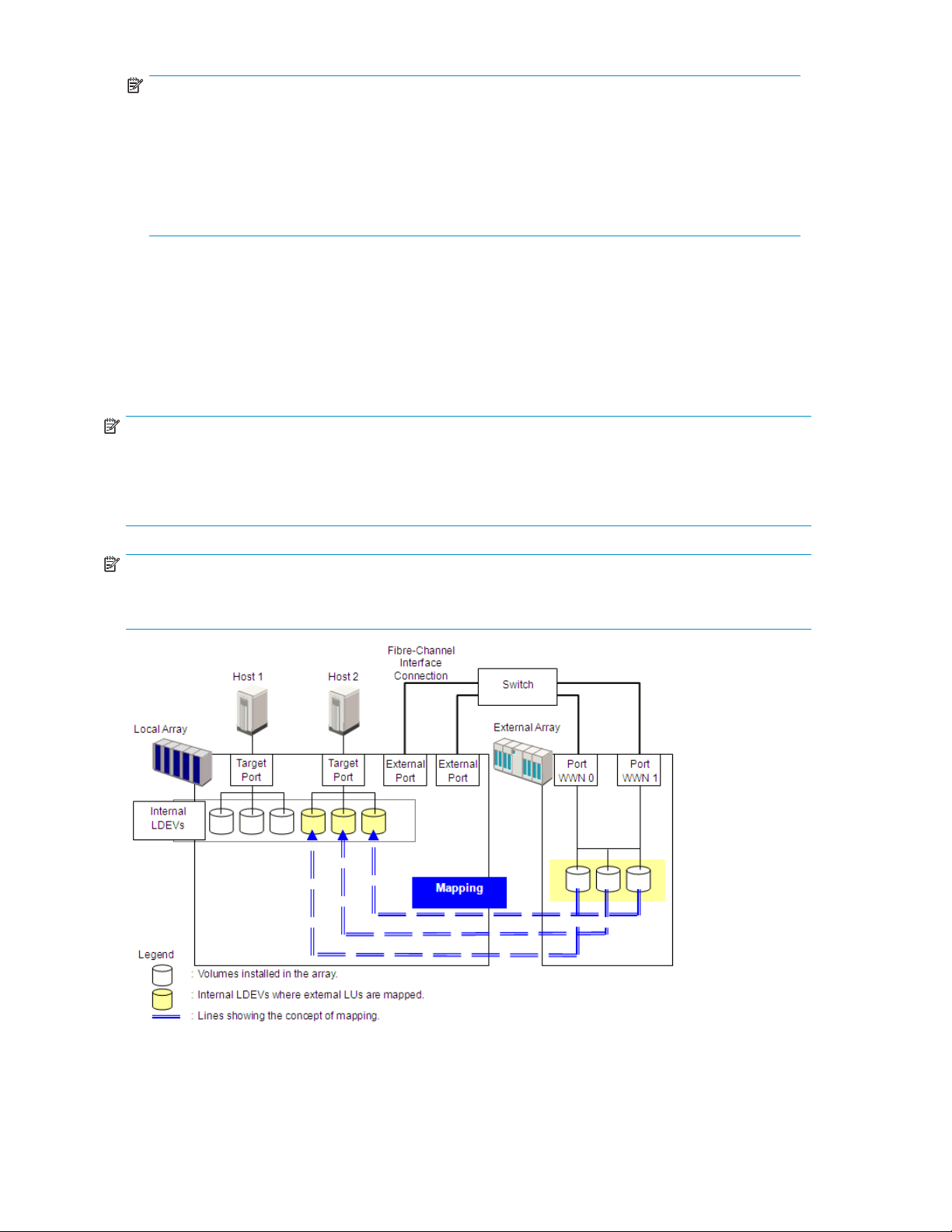
Figure 1 illustrates a local array and an external array that are connected using External Storage XP
and Fibre Channel hardware. In Figure 1, the external array is connected to the external port of the
localarrayviaaswitch(orhub)usingaFibreChannelinterface. Externalisalocalarrayportattribute
used for External Storage XP. In Figure 1, external LUs are mapped as local array VDEVs and LDEVs
and, consequently, as an LU.
NOTE:
Do not access any external storage volume that is mapped as an External Storage XP volume from a host
connected directly to the external array. Also, do not access an External Storage XP mapped external
array volume using the external array's functions (for example, local replication). After mapping an
external LU as a local array volume, access the mapped external LU only from the local array.
NOTE:
Except on the MSA, a host can directly access external array volumes that have not been mapped
as local array volumes.
Figure 1 External Storage XP concept
16
Overview of connecting external arrays
Page 17
2 Preparing for External Storage
XP operations
This chapter describes requirements, preparations, and notes for External Storage XP. This chapter also
describes the HP StorageWorks products you can use with External Storage XP.
System requirements
External Sto
the licensed
System requ
• Local array (first array)
Install and enable all hardware and microcode required for External Storage XP operations in the
local array
CAUTION:
Before inst
storage fo
NOTE:
Currently only an XP12000/XP10000/SVS200 can be used as a local array.
• External array (second array)
You also need a second storage device, called an external array in this user guide. For more
information, see Storage arrays that can be connected as external arrays.
• HP StorageWorks Command View XP (running on a user-supplied Windows®-based PC) or
XP Remote Web Console
For instructions on installing and using Command View XP or XP Remote Web Console, see the
HP StorageWorks Command View XP user guide for XP Disk Arrays or the HP StorageWorks XP
Remote Web Console user guide for XP12000/XP10000/SVS200.
rage XP operations involve the local array, a storage array used as an external array, and
External Storage XP feature enabled on Command View XP or XP Remote Web Console.
irements for External Storage XP are:
.
alling and enabling the hardware and microcode, see Managing cache with external
r instructions.
NOTE:
YoumustrunCommandViewXPorXPRemoteWebConsoleinModifymodetoperformExternal
Storage XP operations. In View mode, you can only view External Storage XP information.
• External Storage XP
Enable the licensed External Storage XP feature in Command View XP or XP Remote Web Console.
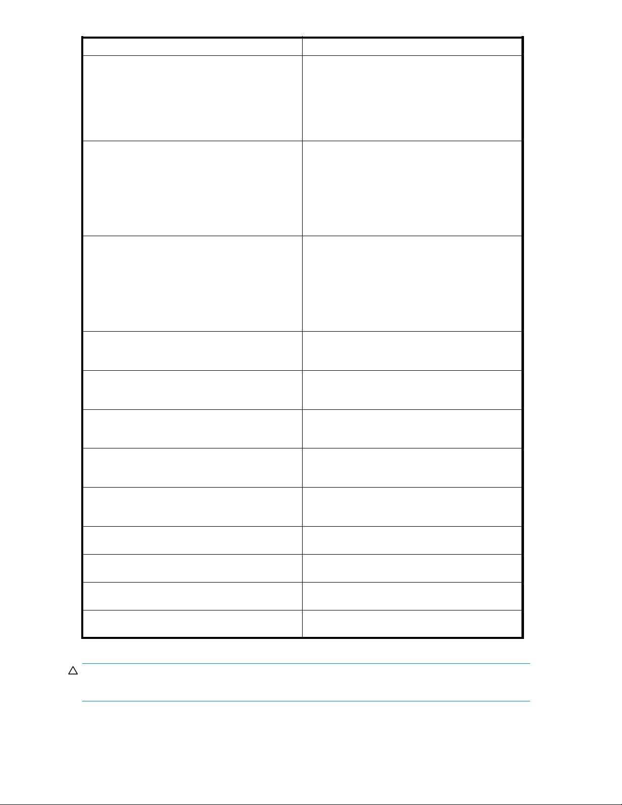
Storage arrays that can be connected as external arrays
Table 2 lists storage arrays that can be connected as external arrays. Notes about the appearance of
each storage array in this document and in External Storage XP panes are also listed.
External Storage XP user guide
17
Page 18

Table 2 Storage arrays that can be connected as external arrays
Storage array
HP StorageWork
HP StorageWorks XP10000 Disk Array
HP StorageWorks XP1024/XP128 Disk Array
HP StorageWorks XP512/XP48 Disk Array
HP StorageWorks XP256 Disk Array
HP StorageWorks 200 Storage Virtualization System
HP StorageWorks 3000/5000 Enterprise Virtual
rray (Active/Standby and Active/Active controllers)
A
r HP StorageWorks 4000/6000/8000 Enterprise
o
Virtual Array (Active/Active controllers)
HP StorageWorks MSA1000/1500 (Active/Standby)
TagmaStore™ Universal Storage Platform subsystem
TagmaStore™ Network Storage Controller subsystem
TagmaStore™ Adaptable Modular Storage subsystem
s XP12000 Disk Array
Notes
• In External Storage XP panes, the array appears
as “12000”.
• Alternate paths are in Multi mode (meaning that
dynamic load balancing across multiple active
pathsisenabled).
• In External Storage XP panes, the array appears
as “10000”.
• Alternate paths are in Multi mode.
• In External Storage XP panes, the arrays appear
as “1024” and “128”, respectively.
• Alternate paths are in Multi mode.
• In External Storage XP panes, the arrays appear
as “512” and “48”, respectively.
• Alternate paths are in Multi mode.
• In External Storage XP panes, the array appears
as “256”.
• Alternate paths are in Multi mode.
• In External Storage XP panes, the array appears
as “SVS200”.
• Alternate paths are in Multi mode.
• In this user guide, the arrays appear as “EVA
array”.
• In External Storage XP panes, the arrays appear
as “EVA”.
• AlternatepathsareinSinglemode(meaningthat
dynamic load balancing across multiple active
paths is not enabled).
• In this user guide, the arrays appear as “MSA
array”.
• In External Storage XP panes, the arrays appear
as “MSA”.
• Alternate paths are in Single mode.
• In this user guide, the array appears as
“TagmaStore™ USP subsystem”.
• In External Storage XP panes, the array appears
as “USP”.
• Alternate paths are in Multi mode.
• In this user guide, the array appears as
“TagmaStore™ NSC subsystem”.
• In External Storage XP panes, the array appears
as “NSC”.
• Alternate paths are in Multi mode.
• In this user guide, the array appears as
“TagmaStore™ AMS subsystem”.
• In External Storage XP panes, the array appears
as “AMS”.
• Alternate paths are in Single mode.
18
Preparing for External Storage XP operations
Page 19

Storage array
TagmaStore™ Workgroup Modular Storage
subsystem
Lightning 99
Thunder 9500V series subsystem
Lightning 9900C series subsystem
A/H-6593 subsystem
SANRISE Universal Storage Platform subsystem
SANRISE Network Storage Controller subsystem
SANRISE Adaptable Modular Storage subsystem
SANRISE Workgroup Modular Storage
00V series subsystem
Notes
• In this user guide, the array appears as
“TagmaStore™ WMS subsystem”.
• In External Storage XP panes, the array appears
as “NSC”.
• AlternatepathsareinSinglemode.
• “Lightning 99xxV series subsystem” indicates the
Lightning 9970V and Lightning 9980V.
• In this user guide, the arrays appear as “Lightning
9900V subsystem”.
• In External Storage XP panes, the arrays appear
as “9970V” and “9980V”, respectively.
• Alternate paths are in Multi mode.
• “Thunder 95xxV series subsystem” indicates the
Thunder9530V,Thunder9570V,andThunder
9580V.
• In this user guide, the arrays appear as “Thunder
9500V subsystem”.
• In External Storage XP panes, the arrays appear
as “9500V”.
• AlternatepathsareinSinglemode.
• “Lightning 99xxC series subsystem” indicates the
Lightning 9910 and Lightning 9960.
• In this user guide, the arrays appear as “Lightning
9900 subsystem”.
• In External Storage XP panes, the Lightning 9910
appearsas“0401”,andtheLightning9960
appears as “0400”.
• Alternate paths are in Multi mode.
• In External Storage XP panes, the array appears
as “300”.
• Alternate paths are in Multi mode.
• In this user guide, the array appears as “SANRISE
USP subsystem”.
• In External Storage XP panes, the array appears
as “USP”.
• Alternate paths are in Multi mode.
• In this user guide, the array appears as “SANRISE
NSC subsystem”.
• In External Storage XP panes, the array appears
as “NSC”.
• Alternate paths are in Multi mode.
• In this user guide, the array appears as “SANRISE
AMS subsystem”.
• In External Storage XP panes, the array appears
as “AMS”.
• AlternatepathsareinSinglemode.
• In this user guide, the array appears as “SANRISE
WMS subsystem”.
• In External Storage XP panes, the array appears
as “WMS”.
• AlternatepathsareinSinglemode.
External Storage XP user guide
19
Page 20
Storage array
SANRISE9900V series subsystem
SANRISE950
SANRISE2000 series subsystem
SANRISE H12000 subsystem
ANRISE H10000 subsystem
S
SANRISE H1024/H128 subsystem
SANRISE H512/H48 subsystem
SANRISE H256 subsystem
0V series subsystem
Notes
• “SANRISE99xxV series subsystem” indicates the
SANRISE9970V and SANRISE9980V.
• In this user guide, the arrays appear as
“SANRISE9900V subsystem”.
• In External Storage XP panes, the arrays appear
as “9970V” and “9980V”, respectively.
• Alternate paths are in Multi mode.
• “SANRISE95xxV series subsystem” indicates
the SANRISE9530V, SANRISE9570V, and
SANRISE9580V.
• In this user guide, the arrays appear as
“SANRISE9500V subsystem”.
• In External Storage XP panes, the arrays appear
as “9500V”.
• Alternate paths are in Single mode.
• “SANRISE2000 series subsystem” indicates the
SANRISE2200 and SANRISE2800.
• In this user guide, the arrays appear as
“SANRISE2000 subsystem”.
• In External Storage XP panes, the SANRISE2200
appears as “0401”, and the SANRISE2800
appears as “0400”.
• Alternate paths are in Multi mode.
• In External Storage XP panes, the array appears
as “12000”.
• Alternate paths are in Multi mode.
• In External Storage XP panes, the array appears
as “10000”.
• Alternate paths are in Multi mode.
• In External Storage XP panes, the arrays appear
as “1024” and “128”, respectively.
• Alternate paths are in Multi mode.
• In External Storage XP panes, the arrays appear
as “512” and “48”, respectively.
• Alternate paths are in Multi mode.
• In External Storage XP panes, the array appears
as “256”.
• Alternate paths are in Multi mode.
IBM Storage Subsystem
EMC Storage Subsystem
Fujitsu Storage Subsystem
NEC Storage Subsystem
For specific supported storage arrays, contact your
HP account support representative.
For specific supported storage arrays, contact your
HP account support representative.
For specific supported storage arrays, contact your
HP account support representative.
For specific supported storage arrays, contact your
HP account support representative.
CAUTION:
For more information about alternate path modes, see Setting alternate paths for external LUs.
20
Preparing for External Storage XP operations
Page 21
Contact your HP account support representative for the latest external array and FC switch support matrix.
External Stora
Table 3 External Storage XP requirements
Item
Required products
Maximum number of external LUs
addressable per local array port
Maximum number of external LUs that
can be connected
Maximum number of FC paths that can
exist to one external LU
ge XP requirements
Requirement
• HPStorageWorksCommandViewXPversion2.0orlater,orXP
Remote Web Console
• HP StorageWorks LUN Configuration and Security Manager
XP (for setup)
• HP StorageWorks RAID Manager XP version 01.12.06 or later
(ifBusinessCopyXPisused)
1, 02 4 p e r p o r t
• For the XP12000, 15,360 volumes can be connected
• For the XP10000/SVS200, 8,192 volumes can be connected
• 1,024 volumes can be connected per port
NOTE:
If you use Snapshot XP, the number of external LUs that can be
connected is as follows:
• For the XP12000:
Number of external LUs + Number of virtual LUs ≤ 15 ,3 6 0
• For the XP10000/SVS200:
Number of external LUs + Number of virtual LUs ≤ 8,192
8
Maximum capacity of an external LU
Minimum capacity of an external LU
2 TB (4,294,967,296 blocks) per external LU (OPEN-V)
If you specify an external LU that is larger than 2 TB, you can only
access data stored in the fieldupto2TB.
About 38 MB (77,760 blocks) per external LU (non-OPEN-V)
When the volume's emulation type is OPEN-V, minimum capacity
is about 47 MB (96,000 blocks) per external LU.
Installing External Storage XP
To perform External Storage XP operations with Command View XP or XP Remote Web Console, you
must install an External Storage XP license key.
1. Start Command View XP or XP Remote Web Console for the local array.
2. Enable the External Storage XP options in Command View XP or XP Remote Web Console and
on each External Storage XP array.
For instructions, see the HP StorageWorks Command View XP user guide for XP Disk Arrays or the
HP StorageWorks XP Remote Web Console user guide for XP12000/XP10000/SVS200.
Preparing for External Storage XP settings
Before using External Storage XP, collect the information necessary for defining its settings. The following
information is required:
• Ports that can be set to external ports (see External ports)
External Storage XP user guide
21
Page 22

• External array and LUs to map to the internal LDEVs (see External LU to be mapped)
• Configuration of external LU groups (see External LU groups)
• Configuration of external LU attributes (see External LU attributes set by mapping)
• Configuration of alternate paths (see Alternate paths)
External ports
Local array ports used for External Storage XP must be set to a designation of External. When the
external array is connected to the local array's external port via Fibre Channel, you can view information
about the external array from Command View XP or XP Remote Web Console. The external array can be
connected on
ly to ports designated as External.
To set the por
You cannot c
Storage XP operations, you must know which ports you can change to External.
NOTE:
Youcannotuseportswithattributessetforremotecopysoftware(suchasRCU Target or Initiator)or
other features as external ports for External Storage XP. If the port attribute is set to something other
than Extern
XP12000/X
For instructions, see Setting a local array's port attributes.
t attribute to External, you must release any existing paths currently configured for the port.
hange the attribute of the port where paths are set to External. Before starting External
al, change its attribute to External. Flex Copy XP and External Storage XP can share an
P10000/SVS200 port with an attribute of External.
External LU to be mapped
When connecting an external array to an external port, you can map LUs in the external array (external
LUs) as LDEVs in the local array (internal LDEVs). Verify which LUs in which external array can be
mapped as internal LDEVs.
You can map only one external LU to a given internal LDEV and map up to a theoretical limit of 1,024
external LUs per local array port.
An external LU's maximum available capacity depends on the emulation type set when the LU is mapped.
You cannot access data stored in the field over the external LU's maximum available capacity. To set an
emulation type other than OPEN-V, you cannot map external LUs smaller than 38 MB (77,760 blocks). To
set the OPEN-V emulation type, you cannot map external LUs of smaller than 47 MB (96,000 blocks). For
more information about the capacity of the external LU for each emulation type, see Required volume
capacity for emulation types.
External LU groups
When mapping an external LU as an internal LDEV, you must register the external LU in an external
LU group.
You can classify external LUs set by External Storage XP into groups according to their use. The group is
called an external LU group (ExG). For instance, you can register several LUs in one external array to one
external LU group. Or, if data you want to manage in a chunk is stored in LUs in various external arrays,
you can register those LUs in one external LU group, and manage them as a block.
You must assign a number from 1 to 16,384 to each external LU group. For the XP12000, you can create
a maximum of 15,360 external LU groups. For the XP10000/SVS200, you can create a maximum of
8,192 external LU groups. You can register a maximum of 256 volumes in one external group.
External LU attributes set by mapping
When mapping an external LU as an internal LDEV, use the Add LU pane in External Storage XP to set the
external LU's attributes. For instructions, see Mapping external LUs (Add LU).
22
Preparing for External Storage XP operations
Page 23

The following are the external LU's attributes:
• Emulation type
Set the mapped LU's emulation type by selecting any emulation type from the drop-down list. However,
if you plan to use the mapped LU for Flex Copy XP operations, or you plan to access existing data in
the external LU, you must select the OPEN-V emulation type to avoid data resizing.
If you plan to use existing data in the external LU from the local array after mapping, you must select
the OPEN-V emulation type. For example, to migrate existing data in the external LU to the local array
volume, you must set the OPEN-V emulation type when mapping the external LU.
You must also select the OPEN-V emulation type when VMA of LUN Security XP Extension is set
for the external LU on the external array side.
If you select an emulation type other than OPEN-V, additional space is taken for XP management
information. This means that after mapping, LU capacity is less than the actual external LU capacity
(andtheoriginaldatamustbeconsideredlost). Formoreinformationaboutvolumecapacity,see
Limitations on External Storage XP operations.
• IO Suppression mode (Enable or Disable)
When mapping an LU, determine whether to suppress I/O operations from hosts (via the local array)
to the mapped external LU.
If you select Enable, you can use the mapped LU only for Flex Copy XP operations.
If you select Disable, a host connected to the local array can use the mapped external LU as if it were
an LU inside the local array, but you cannot use the LU for Flex Copy XP operations.
You can select Enable only when you set the OPEN-V emulation type for the mapped LU. When you
set an emulation type other than OPEN-V, the IO Suppression mode is automatically set to Disable.
• Cache Mode (Enable or Disable)
Cache mode specifies if I/O from the host is propagated synchronously or asynchronously to the
external storage device. All I/O to and from the local array in both cache modes always uses some
amount of cache. Write operations are always backed up in duplex cache.
If you select Enable, the local array signals the host that an I/O operation completed after receiving
the data into the local array's cache memory, and then asynchronously destages the data to the
external array's cache where it is asynchronously destaged to disk.
If you select Disable, the local array signals the host that an I/O operation completed only after the
local array has synchronously written the data to the external array's cache. The external array's
cache then asynchronously destages this data to disk.
NOTE:
Users should disable cache for low price/performance arrays, such as the HP MSA arrays. The MSA
array ports are slower than the XP FC ports. Disabling cache prevents applications that use the MSA
from consuming significant amounts of XP cache.
NOTE:
As an option, consider using XP Disk/Cache Partition as a recommended best practice for managing
XP cache consumption. See Managing cache with external storage or contact your HP account
support representative for more information about optimizing cache usage for external storage.
When IO Suppression mode is set to Enable, Cache Mode changes by default to Disable.
If you use an external LU and set Cache Mode to Disable for Cache LUN XP operations, you cannot
use the Cache LUN XP Bind mode. For more information, see the HP StorageWorks Cache LUN XP
user guide for XP12000/XP10000/SVS200.
External Storage XP user guide
23
Page 24

NOTE:
If you set the emulation type of the mainframe system for the mapped LU, host I/O is always
propagated asynchronously to the external LU regardless of the Cache Mode setting.
• CLPR
When using XP Disk/Cache Partition to partition cache memory, set the cache logical partition
(CLPR) used for accessing the mapped LU. You can also specify whether the CU selected at mapping
is restricted to the storage management logical partition (SLPR) the CLPR belongs to. For more
information about CLPRs and SLPRs, see the HP StorageWorks XP Disk/Cache Partition user guide.
Alternate paths
When mapping an external LU as an internal LDEV, paths are set from the internal LDEV to the external LU.
If two or more paths to the external LU are equipped from different clusters, the number of paths you set
when mapping the volume are available. If one path is equipped, only that path is available.
You can set up to eight paths to each external LU, including paths automatically set. Among the paths
to the external LU, the path with the highest priority is called the primary path, and other paths are
alternate paths.
AlternatepathmodesincludeSinglemodeandMultimode.Thealternatepathmode,Singlemodeor
Multi mode, depends on the connected external array. For Single mode, only the path with the highest
priority (primary path) is used to execute I/Os to the external LU. When an error occurs in the primary
path, the path with the second highest priority is used (that is, no per-LU dynamic load balancing across
paths). For Multi mode, all set paths are used at the same time. The paths are used to execute I/Os to
the external LU, distributing the work load (round-robin processing).
Examp
Forexample,whenanexternalLUvolumewithanalternatepathinSinglemodeismappedtoan
internal LDEV using External Storage XP, host I/O operations to the external LU via the local array are
normally enabled using the mapped path. If the mapped path is not available (for instance, during array
maintenance or following a failure in the channel processor), the path is switched automatically to the
alternate path (if available). As long as an alternate path is available, host I/O operations continue as
usual, even when an error occurs in the original path.
NOTE:
When the primary path cannot be used for the length of the Path Blockade Watch timer(forexample,
180 seconds), the path is switched to an alternate path.
If you have not configured any alternate paths, host I/O operations are suspended when the primary
path becomes unavailable (such as during array maintenance operations or following a failure in the
channel processor).
HP recommends configuring alternate paths for safer operation and increased bandwidth. For
instructions, see Setting alternate paths for external LUs.
You can set alternate paths when the external LUs are mapped as the internal LDEVs (see Mapping
external LUs (Add LU)). You can also set alternate paths after completing the mapping operation (see
Setting alternate paths for external LUs).
le of an alternate path configuration
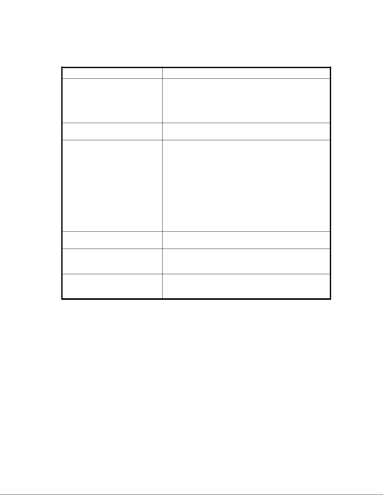
e2shows an example of an alternate path configuration. In Figure 2,externalarrayportsWWNA
Figur
and WWN B are connected to CL1-A and CL2-A, respectively, which are designated as external ports in
the local array. You must specify the port of a different cluster in the local array for the alternate path, as
ports CL1 and CL2 are specified in the figure.
24
Preparing for External Storage XP operations
Page 25
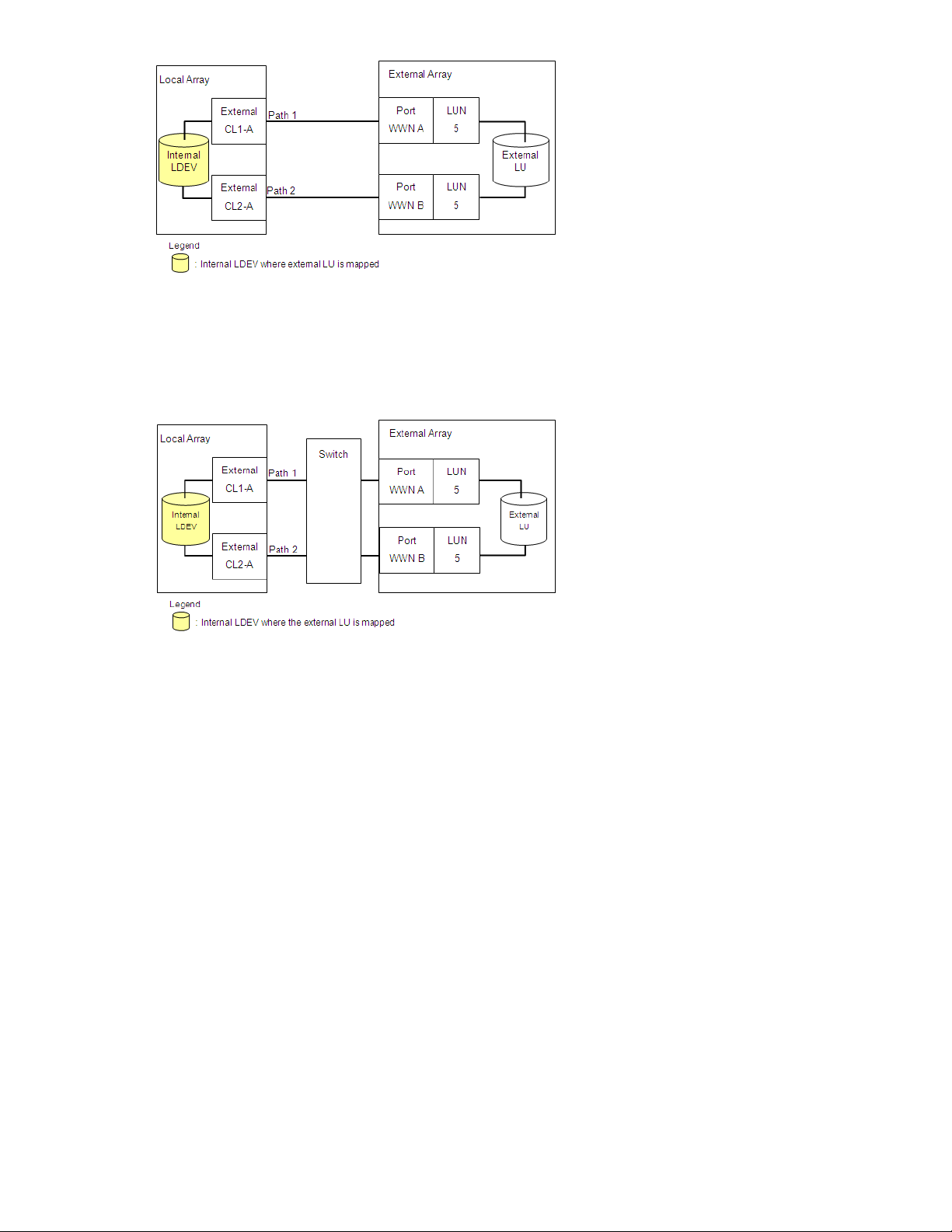
Figure 2 Example of alternate path configuration
Figure 3 shows another example of an alternate path configuration. In Figure 3,twoportsarespecified
in the local array and connected to ports in the external array via switches. In this example, two ports
from different XP12000/XP10000/SVS200 clusters are specified in the local array, thereby making it
possible to configure an alternate path for high availability.
Figure 3 Example of alternate path configuration using two switches
In Figure 4, two paths are configured between the internal LDEV and external LU. However, only one port
is specified in the local array and two ports are specified in the external arrays via the switch. Since
two port
settin
s of different clusters must be set in the local array for External Storage XP to use alternate path
gs, HP does not recommend the configuration shown in Figure 4.
External Storage XP user guide
25
Page 26
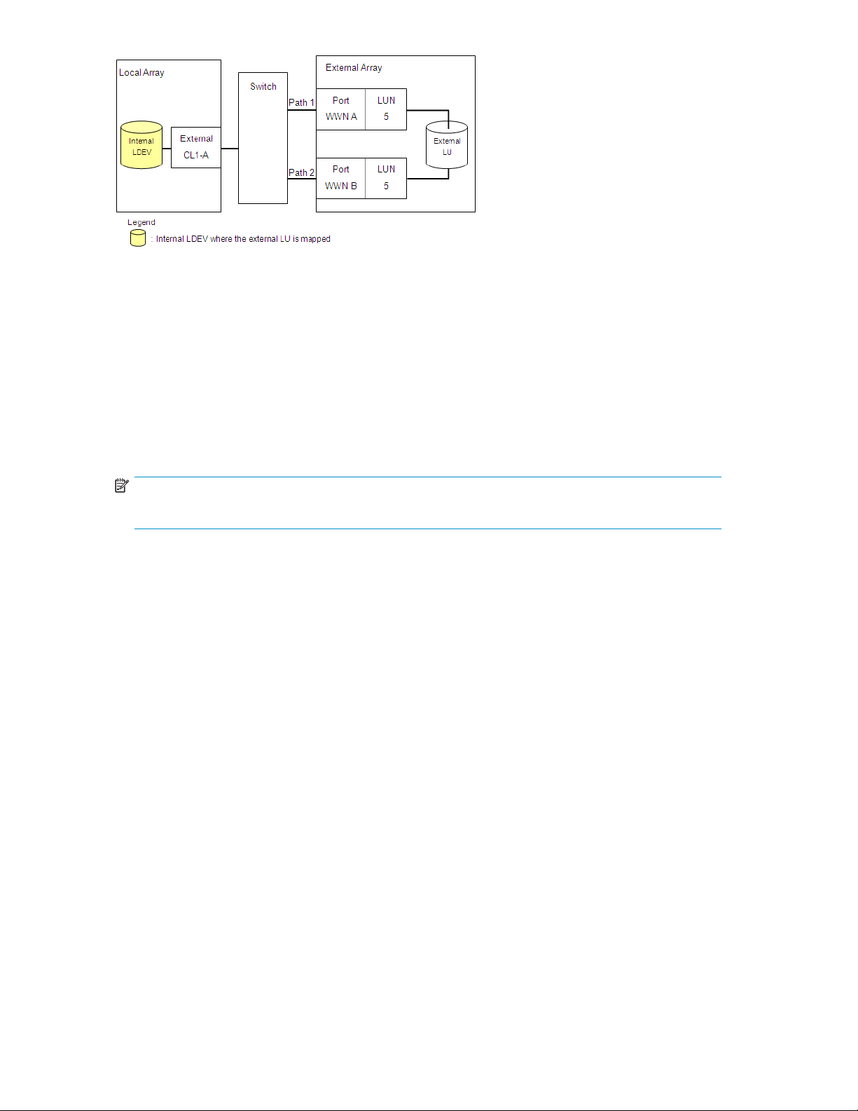
Figure 4 Example of incorrect alternate path configurations
Examples of switching I/O execution paths to alternate paths
There are two alternate path modes: Single mode and Multi mode. This section describes examples of
the performance when the I/O execution path switches to the alternate path for each path mode.
For more information about path status, see Adding alternate paths by selecting multiple external LUs
(Add Paths).
• Alternate path mode is Multi mode
Figure 5 shows an example of when the alternate path mode is Multi mode. When an error occurs
in one path, I/Os execute using paths other than the error path.
NOTE:
As you restore the error path, use of the restored path automatically resumes.
26
Preparing for External Storage XP operations
Page 27
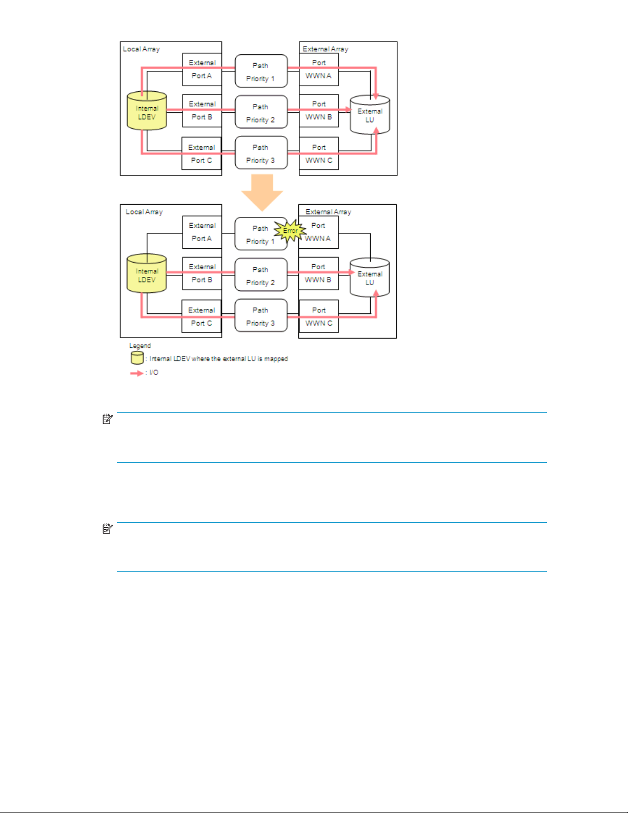
Figure 5
Alternate path mode is Multi mode
NOTE:
In Multi
and EMC D
mode, active I/O load balancing occurs across external array ports and controllers. The XP
MX are examples of external arrays that use Multi mode.
• Alternate path mode is Single mode
Figure 6 shows an example of when the alternate path mode is Single mode. When an error occurs
in the path used for I/Os, the I/O execution path switches to the path with the second highest priority.
NOTE:
As you restore the path with a priority higher than the current path, the I/O execution path
automatically switches to the restored path with the highest priority.
External Storage XP user guide
27
Page 28
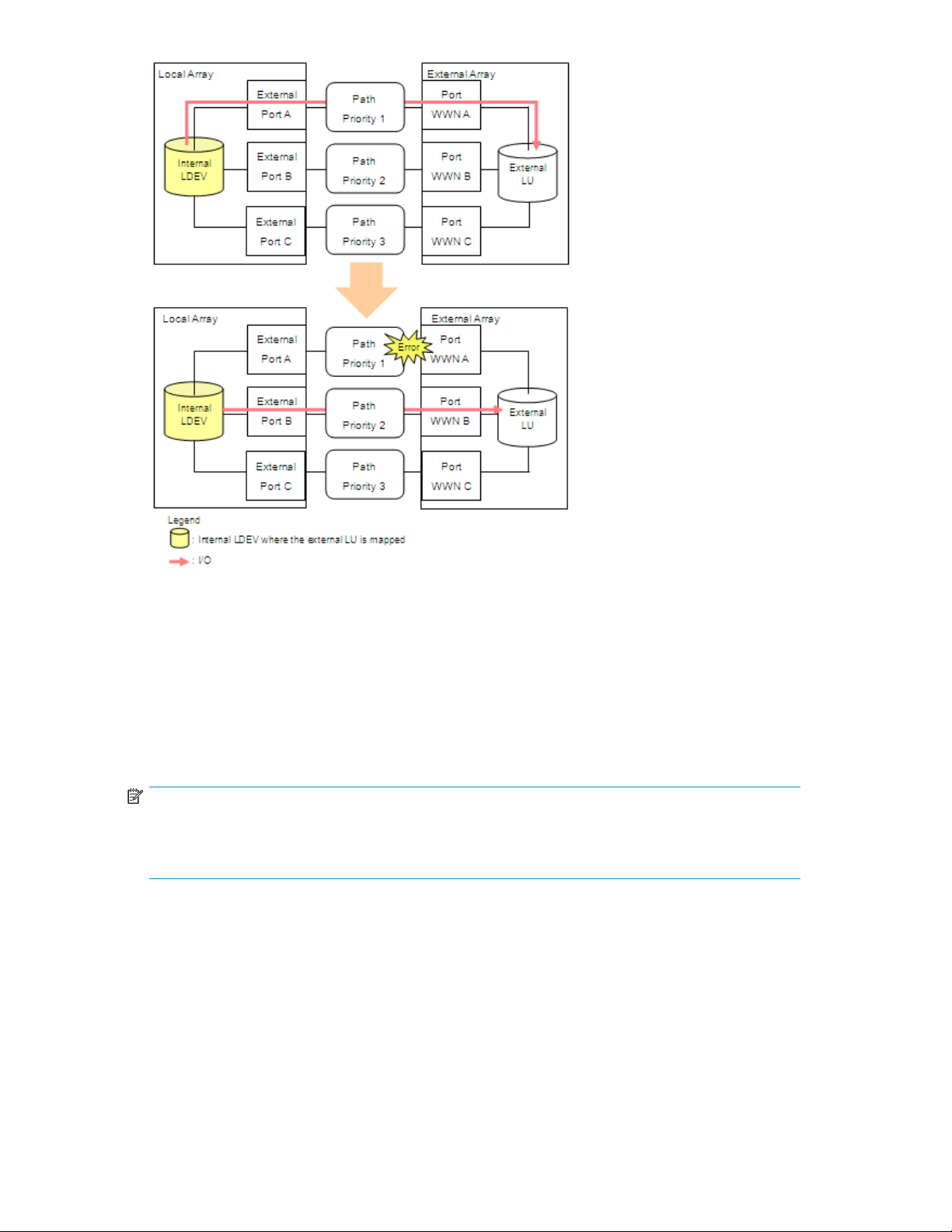
Figure 6 Alternate path mode is Single mode
• Alterna
te path mode is Single mode and at least one alternate path is in Standby status
Figure 7
paths in
shows an example of when the alternate path mode is Single mode and there are alternate
Normal and Standby status. Figure 8 shows another example of when the alternate path
mode is Single mode. In Figure 8, there are alternate paths in Standby status only.
When an error occurs in the path used for I/Os, the I/O execution path switches to the path with the
second highest priority in Normal status (Figure 7). If there is no path in Normal status other than the
path used for I/Os, the status of the path in Standby status automatically changes to Normal and the
I/O execution path switches to that path (Figure 8).
NOTE:
When the external array is an EVA array, as you restore the path with the highest priority, the I/O
execution path switches back to the restored highest priority path. In this case, the status of the path
for which the status changed to Normal when the error occurred changes back to Standby.
28
Preparing for External Storage XP operations
Page 29
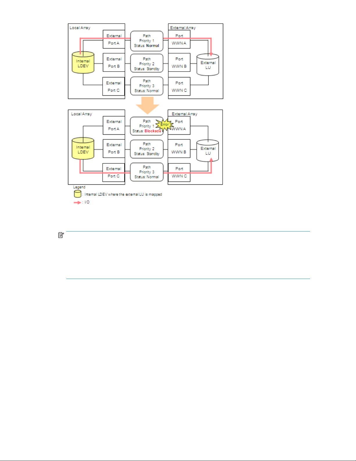
Figure 7 Alternate path mode is Single mode with alternate paths in Normal and
Standby
NOTE:
Externa
l arrays with Asymmetrical Active/Active (AAA) controllers, such as the Hitachi Thunder, are
an example of Figure 7. A notable characteristic of using AAA controller arrays as external storage
is that paths to alternate ports on the owning controller for a given external LU are seen as Normal
status, but I/O load balancing does not occur (either across controllers or across ports to the owning
controller). Paths to the non-owning external controller's ports are shown as Standby status.
External Storage XP user guide
29
Page 30
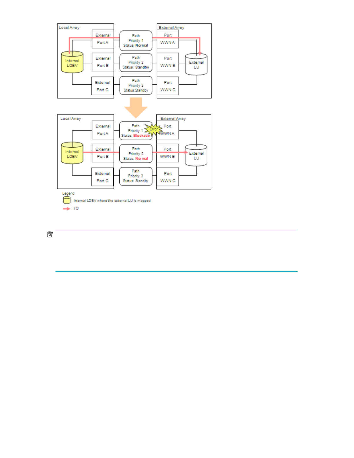
Figure 8 Alternate path mode is Single mode with alternate paths in Standby only
NOTE:
External arrays with Active/Standby (A/S) controllers, such as the MSA, are an example of Figure 8.
A notable characteristic of using A/S controller arrays as external storage is that there is typically
only a si
shown a
ngle port to the owning controller. Paths to the non-owning external controller's ports are
s Standby status. I/O load balancing does not occur across external controllers.
Powering arrays on or off
This section describes procedures for powering local and external arrays on or off after External Storage
XP operations have started.
The procedures below will utilize the following commands:
• Disconnect Subsystem
Execute the Disconnect Subsystem command from the Command View XP or XP Remote Web Console
GUI when you need to perform maintenance or stop the local or external array. This command stops
acceptance of all host I/O operations to the external LU mapped as the internal LDEV. All outstanding
data in cache memory on the local array intended for the external LU is written (de-staged) to the
external LU.
For instructions on executing the Disconnect Subsystem command, see Disconnecting external arrays
or LUs.
30
Preparing for External Storage XP operations
Page 31

NOTE:
To disconnect an individual LU, use the Disconnect Volume command. To delete a single external LU's
mapping, use the Disconnect Volume command and then the Delete LU command. For instructions,
see Deleting external LU mappings (Delete LU).
• Check Paths & Restore Vol.
This command checks if defined information about the mapped external LU and the actual external LU
status match. If the external LU can be used as the mapped local array volume, the external LU is set
to accept I/O, and you can continue using the external LU as a mapped LU.
Use this command to restore the external LU, which is set to reject host I/O operations by the
Disconnect Subsystem or Disconnect Volume command, as the mapped volume. You can execute the
Check Paths & Restore Vol. command for the entire array or an individual LU.
If an error occurs in the external storage path such that the command fails, correct the error so the
path can be restored, and execute the Check Paths & Restore Vol. command again.
For instructions, see Checking the connection status and resuming external LU operations (Check
Paths & Restore Vol.).
NOTE:
When executing the Check Paths & Restore Vol. command, if the external LU is ready to be restored
as the mapped LU, the external LU is set to Available. However, if the external LU is not ready to be
restored, the external LU status remains as Blocked.
The followin
CAUTION:
To power both the local and external arrays off, first power off the local array, and then power off
the external array.
CAUTION:
To power both the local and external arrays on, first power on the external array, and then power on
the local array. If both are supplied by a common failed power source, one option to ensure that the
external array is online and available before the XP powers up is to place the external array on an
Uninterruptible Power Supply (UPS).
Powering l
ocal arrays on or off
g sections describe procedures to power the local and external arrays on or off.
To power local arrays off
CAUTION:
When you want to turn off both the local array and the external array, you first need turn off the local
array,andthenturnofftheexternalarray.
1. Stop read and write I/Os to the external LU that is mapped as a local array internal LDEV.
2. Perform other operations required before powering the local array off.
3. Turn the local array's power off.
External Storage XP user guide
31
Page 32

NOTE:
Asyouturnthelocalarray'spoweroff,alldatafortheexternalLUinthelocalarray'scachememoryis
written in the external LU (all data is destaged).
To power local arrays on
CAUTION:
Whenyouwanttoturnonboththelocalarrayandtheexternalarray,youfirst need to turn on the external
array,andthenturnonthelocalarray.
1. Power on the external array containing the external LU mapped as a local array internal LDEV.
2. Turn on the local array's power.
CAUTION:
When the local array is powered off after executing the Disconnect Subsystem command, you cannot
access the mapped external LU from the local array when you first power on the local array. You must
execute the Check Paths & Restore Vol . command to resume using the mapped external LU. The Check
Paths & Restore Vol.commandchecksifthedefinedinformationandactualstatusoftheexternalLU
mapped as a local array volume match. If the external LU is ready to be used as a mapped volume, the
LUissettoacceptI/Osandyoucanresumeusingthevolumeasamappedvolume.
CAUTION:
When the Disconnect Subsystem or Disconnect Volume commandisexecutedandalldataincache
memory is written to the external LU, the displayed information for Ex-Dev. Status in the Device list
becomes Disconnect.
Powering external arrays on or off
To power ex
ternal arrays off
1. Stop read and write I/Os to the external LU that is mapped as a local array internal LDEV and is
located in the external array you want to power off.
2. Execute t
Additional I/O to the external LU is stopped and all data in the local array cache memory is written
to the external LU (all data is destaged). For instructions, see Disconnecting external arrays or LUs.
3. Perform other operations required before powering the external array off.
4. Power the external array off.
CAUTION
After ex
execute the Check Paths & Restore Vol.command.
he Disconnect Subsystem command for the external array you want to power off.
:
ecuting the Disconnect Subsystem command, if you need to use the mapped external LU again,
To power external arrays on
1. Power on the external array containing the external LU that is mapped as a local array internal LDEV.
32
Preparing for External Storage XP operations
Page 33

2. Execute the Check Paths & Restore Vol.command.Forinstructions,seeChecking the connection
status and resuming external LU operations (Check Paths & Restore Vol.).
CAUTION:
When powering the external array off after executing the Disconnect Subsystem command, you cannot
access the mapped external LU from the local array when you initially turn on the external array. You
must execute the Check Paths & Restore Vol. command to resume using the mapped external LU. The
Check Paths & Restore Vol.commandchecksthedefined information and the actual status of the
external LU mapped as a local array internal LDEV. If the external LU is ready to be used as a mapped
volume, the LU is set to accept I/Os and you can resume using the LU as a mapped volume.
TurningOnorOffPowerSupplyofBothlocalandexternalarrays
This section explains how to turn on or off the power supply of both the local and external array using HP
StorageWorks Business Copy.
To turn OFF the power supply of both arrays:
1. Stop all read or write I/Os to the local array.
2. If you use NAS, stop the NAS Blade system. For details on how to stop the NAS Blade system,
see Troubleshooting NAS Blade systems that include external arrays.
3. Split all HP StorageWorks Business Copy pairs (pairsplit operation). For details on the pairsplit
operation, refer to HP StorageWorks Business Copy User’s Guide.
4. Turn off the power supply of the local array.
CAUTION:
Make sure that the power supply of the local array is completely off and then go on to the next step.
5. Turn off the power supply of the external array.
CAUTION:
Make sure that the power supply of the external array is completely off.
To turn ON the power supply of both arrays :
1. Turn on the power supply of the external array.
CAUTION:
Make sure that the power supply of the external array is completely on and then go on to the next step.
2. Turn on the power supply of the local array.
CAUTION:
Make sure that the power supply of the local array is completely on and then go on to the next step.
3. Resynchronize all HP StorageWorks Business Copy pairs (pairresync operations). For details on the
pairresync operation, refer to HP StorageWorks Business Copy User’s Guide.
4. If you use NAS, start the NAS Blade system. For details on how to start the NAS Blade system, see
Troubleshooting NAS Blade systems that include external arrays.
5. Start the read or write I/Os to the local array.
External Storage XP user guide
33
Page 34

Using mapped external LUs from the host connected to the
local array
The following sections describe examples of using the mapped external LU from the host connected
the local array
Writing new data to mapped external LUs
Figure 9 shows an example of writing new data in the mapped external LU from the host connected to
the local array.
1. Use the External Storage XP GUI to map the LU in the external array as an internal LDEV of the
local array.
CAUTION:
You can select the mapped volume's emulation type as required. If you select an emulation
type for an open-system (such as OPEN-V), go to step 2. If you select an emulation type for
amainframesystem(suchas3390-3),gotostep3
For more information, see Mapping external LUs (Add LU).
2. For open-system emulation types (such as OPEN-V, which HP recommends), the status of the mapped
LDEV is set to Normal and is not automatically formatted. To optimally initialize the mapped LU's
data area, use Volume Manager to format the mapped LU. For instructions, see the HP StorageWorks
LUN Configuration and Security Manager XP user guide for the XP12000/XP10000/SVS200.
Go to step 4.
.
3. For mainframe-system emulation types (for example, 3390-XX), the status of the mapped LU is set
to Blockade, pending resizing and formatting. Use Volume Manager to format the volume. If you
mapped a volume for which the data area is already zero-formatted on the external array side,
use Volume Manager's Write to Control Blocks operation to restore the volume. For instructions,
see the HP StorageWorks LUN Configuration and Security Manager XP user guide for the
XP12000/XP10000/SVS200.
4. Configure the path from the Target port to the mapped volume to perform host I/O operations. The
mapped LDEV is available for host I/O operations.
After the path is set, host I/O operations to the mapped LU are available.
34
Preparing for External Storage XP operations
Page 35

Figure 9 Writing new data to mapped external LUs
Using exi
Figure 10
the local array.
1. From the host connected to the external array, write data to the LU in the external array.
2. Use Exte
3. Configure the path from the Target port to the mapped LU to perform host I/O operations.
stingdatainmappedexternalLUs
shows an example of using existing data in a mapped external LU from the host connected to
rnal Storage XP to map the LU in the external array containing data as an internal LDEV of
the local array.
When mapping the external LU, set the following attributes for the mapped LU:
•Emulati
• IO Suppression mode: Disable
For more information, see Mapping external LUs (Add LU).
CAUTION:
You must set the emulation type to OPEN-V to read existing data in the mapped external LU
from the local array side. Other emulation modes require that the data space be resized,
which i
for use
the em
the external LU on the external array side.
After the path is set, host I/O operations to the mapped volume are available.
on type: OPEN-V
n effect destroys existing data. Once an external LU is mapped to the local array
by External Storage XP, direct host access to that LU is no longer allowed. Also set
ulation type to OPEN-V when the VMA of LUN Security XP Extension is set for
External Storage XP user guide
35
Page 36

NOTE:
Do not access any external storage volume that is mapped as an External Storage XP volume from a
host connected directly to the external array. Also, do not access an External Storage XP mapped
external array volume using the external array's functions (for example, local replication). After mapping
an external disk volume as a local array volume, access the mapped external disk volume only via
the local array.
NOTE:
Except on the MSA, a host can directly access external array volumes that are not mapped as local
array volumes.
Figure 10 Using existing data in mapped external LUs (without formatting)
Uninstalling External Storage XP
To uninstall External Storage XP, cancel any existing Flex Copy copy pairs, and delete any external LU
mappings.
1. Log in to Command View XP or XP Remote Web Console. For instructions, see the HP StorageWorks
Command View XP user guide for XP Disk Arrays or the HP StorageWorks XP Remote Web Console
user guide for XP12000/XP10000/SVS200.
2. Click the External Storage XP button (
3. Cancel any existing Flex Copy pairs. For instructions, see the HP StorageWorks Flex Copy XP
user guide.
4. Delete any external LU mapping. For instructions, see Deleting external LU mappings (Delete LU).
5. Use the Command View XP or XP Remote Web Console Licensing module to remove the Flex
Copy XP license key. For instructions, see the HP StorageWorks Command View XP user
36
Preparing for External Storage XP operations
). External Storage XP starts.
Page 37

guide for XP Disk Arrays or the HP StorageWorks XP Remote Web Console user guide for
XP12000/XP10000/SVS200.
6. For the local array, use the Command View XP or XP Remote Web Console Licensing module to
remove the External Storage XP license key. For instructions, see the HP StorageWorks Command
View XP user guide for XP Disk Arrays or the HP StorageWorks XP Remote Web Console user
guide for XP12000/XP10000/SVS200.
Limitations on External Storage XP operations
• External LU
• Only ports in SLPR0 can be set as external ports.
• DonotaccessanyexternalstoragevolumethatismappedasanExternalStorageXPvolume
from a host connected directly to the external array. Also, do not access an External Storage XP
mapped external array volume using the external array's functions (for example, local replication).
After mapping an external disk volume as a local array volume, access the mapped external
disk volu
• Except on the MSA, a host can directly access external array volumes that have not been mapped
as local array volumes.
• Continuo
• HPdoesnotrecommendthatvolumesinvolvedwithSnapshotXPresideonexternalMSAarrays.
• If you map an external LU that is more than 2 TB with the setting of OPEN-V emulation type, you
can access data stored in the fieldupto2TB.Youcannotaccessdatastoredinthefield over 2 TB.
• When ma
LU) wit
capacity as the mapped external LU. That is, no space is forfeited for management space, and no
formatting of that data occurs. Therefore, OPEN-V is recommended.
s can be mapped as any CU:LDEV combination from 00:00 to 3F:FF.
me only via the local array.
us Access XP P-VOLs, S-VOLs, and journal volumes are not supported on MSA arrays.
pping a volume that has a capacity of 2 TB or less in the external array and (external
h the OPEN-V emulation type, the LU is defined as an internal LDEV with the same
Figure 11 Example of external LU with 2 TB or less
• If you map an external LU that is equal to or greater than 575.98 GB with an OPEN emulation
type other than OPEN-V, you can access data stored in the fieldupto575.98GB.Youcannot
access data stored in the field over 575.98 GB.
However, for emulation types with a small base capacity, some of the field of 575.98 GB might not be
available. For more information, see Required volume capacity for emulation types.
• If you map an external LU that is equal to or greater than 575.98 GB with a 3380 mainframe
emulation type, you can access data stored in the field up to 575.98 GB. You cannot access data
stored in the field over 575.98 GB.
However, for emulation types with a small base capacity, some of the field of 575.98 GB might not be
available. For more information, see Required volume capacity for emulation types.
• If you map an external LU that is equal to or greater than 695.98 GB with a 3390 mainframe
emulation type, you can access data stored in the field up to 695.98 GB. You cannot access data
stored in the field over 695.98 GB.
However, for emulation types with a small base capacity, some of the field of 695.98 GB might not be
available. For more information, see Required volume capacity for emulation types.
External Storage XP user guide
37
Page 38

• If you plan to use the mapped external LU from the mainframe OS (volume is mapped with a
3380-x or 3390-x mainframe emulation type), you must select an external LU that consists of one
LDEV or you must first adjust the capacity of the external LU to be mapped. If multiple LDEVs exist
inoneexternalLUandifnumerousI/OsaremadetotheseLDEVs,thereadandwritecommands
might timeout. When the commands timeout, the SIM (21D2xx) is reported.
• When mapping an external LU as internal LDEVs with emulation types other than OPEN-V, the
number of volumes and the volume capacity of the mapped internal LDEVs depends on the
original external LU's capacity and each emulation type's normal size. When mapping an
external LU using emulation types other than OPEN-V, an XP array management information area
is required in the mapped LU. This means that the capacity available after mapping is slightly
smaller than the actual external LU capacity. Available capacity decreases by the size of the
XP array management information area, and all prior data must be considered lost. For more
information, see the HP StorageWorks Flex Copy XP user guide.
Figure 12 shows an example where the external LU's original capacity is larger than (or a multiple
of) the normal size of the local array's emulation type (OPEN-3 in this example). Therefore, in this
example, the local array can realize two fully-sized OPEN-3 LDEVs, with some space (insufficient to
create a full OPEN-3) left over.
Figure
12 Ext. LU cap. is larger than the spec. emulation type's basic cap. (OPEN-3
ex.)
Figure 13 shows an example where the external LU's original capacity is smaller than the normal
size of the local array's emulation type. In this example, since the resulting space is insufficient to
create a local array OPEN-3 LDEV, you can designate it as either a local array OPEN-V or an
OPEN-3 CVS LDEV. If the external LU were an XP of OPEN-3 emulation type, forfeiting a small amount
of management space would also result in an OPEN-3 CVS volume or an OPEN-V.
Figure 13 External LU capacity is smaller than the specified emulation type's basic
capacity
• IO Suppression mode can only be selected when the volume being mapped is set to the OPEN-V
emulation type. If a different emulation type is set, IO Suppression mode is automatically set
to Disable.
38
Preparing for External Storage XP operations
Page 39

• If you use the mapped external LU from the host connected to the local array, set the IO
Suppression mode to Disable when mapping the LU. For External Storage XP, select Disable.For
Flex Copy XP, select Enable.
• If you use the mapped external LU for the copy source or copy destination volume for a Flex Copy
XP pair, set the emulation type to OPEN-V when mapping the volume.
• If you use the mapped external LU for the copy source or copy destination volume for a Flex Copy
XP pair, set IO Suppression mode to Enable when mapping the volume.
• The local array does not force the external array to reserve the mapped external LU. Therefore, do
not write directly to an external array LU (that is, without writing via the local XP array) with IO
Suppression mode set to Disable from the external array side.
If Flex Copy XP operations are in progress for a volume with IO Suppression mode set to Enable,be
careful when updating data in that external LU from the external array side.
• IO Suppression mode is automatically set to the same status for all LDEVs in a given external LU.
• Cache Mode is automatically set to the same status for all LDEVs in a given external LU.
• If you set an open-system emulation type (such as OPEN-V) when mapping the external LU, you
can use the external LU immediately.
To optionally initialize the LU's data area, use Volume Manager to format the LU. For instructions,
see the HP StorageWorks LUN Configuration and Security Manager XP user guide for the
XP12000/XP10000/SVS200.
• If you set a mainframe-system emulation type (such as 3390-3) when mapping the external LU,
format the LU or perform the Write to Control Blocks operation to make the volume usable.
After the mapping operation, the mapped LU's status is Blockade. Use Volume Manager to format the
volume or perform the Write to Control Blocks operation to make the volume usable.
• If you mapped a volume that has already been zero-formatted on the external array side,
perform the Write to Control Blocks operation.
• If you mapped a volume that has not been zero-formatted on the external array side, format
thevolumeonthelocalarrayside.
For instructions on the formatting and Write to Control Blocks operations, see the HP StorageWorks
LUN Configuration and Security Manager XP user guide for the XP12000/XP10000/SVS200.
If you format the external array's mapped LU from the external array side, data that existed prior to
formatting cannot be ensured. When using the mapped external LU from the mainframe OS, format
the mapped volume from the local array side.
• If you set a mainframe-system emulation type for the mapped LU, host I/O is always propagated
asynchronously to the external LU regardless of the Cache Mode setting.
• External LU attributes (IO Suppression mode and Cache Mode) set when the LU is mapped cannot
be changed while the LU is mapped. To change these attributes, delete the external LU mapping
(Delete LU operation), and remap the LU with different attributes (Add LU operation).
• External LU attributes for all LDEVs created in an external LU are set to the same values. Those
attributes are modified when the LDEVs are reconfigured using Volume Manager.
• Mapped volumes that have different external volume attributes (IO Suppression mode, Cache
Mode) cannot be used to create one LUSE volume.
• A mapped external LU with IO Suppression mode set to Enable (such as for Flex Copy XP) cannot
be used for the local array's Cache LUN XP operations.
• For a mapped external LU with IO Suppression mode set to Disable (such as for External Storage
XP), Cache LUN XP's Bind mode is not available.
• If you use the mapped external LU for Cache LUN XP operations and set the bind mode, Cache
LUN XP operations require a cache of twice the capacity of the user data.
• For External Storage XP, IO Suppression mode is typically set to Disable. You cannot use a
mapped external LU with IO Suppression mode set to Enable for pair copy operations in
Continuous Access XP, TrueCopy for z/OS®, Continuous Access XP Journal, Universal Replicator
for z/OS, Business Copy XP, ShadowImage for z/OS, or Snapshot XP. Also, the external LU
cannot be used for automatic Auto LUN XP operations.
External Storage XP user guide
39
Page 40

• Attributes originally set for an external LU on the external array side (such as port security, LUN
security, and Volume Retention Manager attributes) are not kept when the external LU is mapped
as a local array internal LDEV. To keep the original attributes, set those attributes on the mapped
external LU from the local array side.
• If you mapped the external LU and previously set the VMA of LUN Security XP Extension in that
volume, the former VMA setting is superseded when you map the volume again. However, if
LUN Security XP Extension is not installed when you remap the volume, the volume with the VMA
setting cannot be mapped. To change the VMA setting, change it from the local array side.
• Do not combine LDEVs of multiple external volumes to create a LUSE volume. The LDEVs in the
same external volume can only be used to set the LUSE volumes. When you combine LDEVs of
multiple external volumes to create a LUSE volume, you need to consider:
• If a LUSE volume consists of multiple external volumes and one external volume has lower
performance than the other volumes, the lower performance of the volume affects the
performance of the LUSE volume.
• When an external volume which is a component of a LUSE volume is blocked, data reliability
of the LUSE volume will deteriorate because the LUSE volume has both accessible area and
inaccessible area from a host.
• When you disconnect an external volume or resume the use of an external volume, you need
to perform the operation at the same time on all the external volumes which are components
of the LUSE volume.
• Do not update a volume being used or operated by Flex Copy XP. Also do not update the external
LU on the external array side.
• You can delete up to 256 mappings for external LUs at one time.
• Operations cannot be performed if some parts of the local array are blocked. In this case, restore
blocked parts of the local array, and retry the operation.
• When using the Thunder 9500V series subsystem as an external array, the following versions are
recommended. If you use a 9500V array with a version that is earlier than the following versions,
the SATA drive information might not display correctly.
• For Thunder 9530V, Thunder 9520V, Thunder 9570V: version 0658 or later
• For Thunder 9580V, Thunder 9585V: version 1658 or later
• Do not map multiplatform volumes of external arrays as internal LDEVs.
• After executing the Check Paths & Restore Vol., Disconnect Subsystem,orDisconnect Volume
command, click the Refresh button (
) on the Command View XP or XP Remote Web Console
main pane to update the information, and check the current status.
• When t
he external LU's status is Blockade,executetheCheck Paths & Restore Vol. command.
If the Check Paths & Restore Vol. command does not restore the external LU's status, the path to the
external array might be blocked. In this case, see Troubleshooting External Storage XP for instructions
toring the path to the external array.
on res
external LU's status remains Blockade even though you restored the path to the external array
If the
andexecutedtheCheck Paths & Restore Vol. command, execute the Restore command.
• If you execute the Disconnect Subsystem or Disconnect Volume command when I/Os from the
system host are in progress, host I/Os to the specified volume are forcibly stopped. When
open
uting the Disconnect Subsystem or Disconnect Volume command, stop host I/Os, and
exec
ount the volume from the host.
unm
• Ifthevolumeisonlinefromthemainframehost,youcannotexecutetheDisconnect Subsystem
or Disconnect Volume command. Stop host I/Os to the volume, and perform the Vary Offline
ration.
ope
• You cannot execute the Disconnect Subsystem or Disconnect Volume command for external LUs
that include LDEVs set as copy pairs for Flex Copy XP, Business Copy XP, ShadowImage for
z/OS, Continuous Access XP Journal, Universal Replicator for z/OS, Continuous Access XP,
ueCopy for z/OS, or Snapshot XP. However, if the copy pair status is PSUE, you can execute
Tr
these commands. When the external LU is set as a pool volume (pool-VOL) and that Snapshot XP
pair's status is PAIR, you can execute these commands.
40
Preparing for External Storage XP operations
Page 41

• You cannot execute the Disconnect Subsystem or Disconnect Volume command for external LUs
that include LDEVs for which Auto LUN XP's migration processing is in progress.
• When executing the Disconnect Subsystem or Disconnect Volume command, the displayed
information for Ex-Dev. Status in the Device list becomes Cache Destage. Even if there is no data
left in cache memory, the displayed status stays Cache Destage until the Disconnect Subsystem or
Disconnect Volume command processing is complete.
• When the Disconnect Subsystem or Disconnect Volume command is executed and all data in
cache memory is written to the external LU, the displayed information for Ex-Dev. Status in
the Device list becomes Disconnect.
• When using the mapped external LU from the mainframe OS, set the Missing Interrupt Handler
(MIH) timer to 45 seconds, which is the recommended value.
• In the internal processing, the external LU's RAID level is handled as RAID-1 across the board.
A bar (–) appears on the Command View XP or XP Remote Web Console panes. The external
LU's RAID level is reported as RAID-1 when information about the external array is reported to
higher-level devices (OS).
•Table4and Table 5 show the recommended application level for the mapped external LU
according to the external LU's HDD type.
Table 4 When external LU's emulation type is OPEN
Application
HDD type
FC HD-FC S-ATA
Database
Online Transaction Processing (OLTP)
File operation from host
(both Read and Write)
File operation from host
(mainly Read)
Backup
Archive
Not Recommended Not Recommended
OK
OK OK
OK
OK
Table 5 When external LU's emulation type is for mainframes
Application
HDD type
FC HD-FC S-ATA
Database
Online Transaction Processing (OLTP)
System volumes
(Journal, Check points)
Operation from TPF
File operation from host
(both Read and Write)
File operation from host
(mainly Read)
Backup
Archive
Not Recommended Not Recommended
Not Recommended Not Recommended
NotSupported NotSupported
OK
OK OK
OK
OK
Not Recommended
Recommended
Recommended
Not Recommended
Recommended
Recommended
• The external array's performance and status affect the mapped external LU's Read and Write
performance. If there is a heavy load on the external array, the Read and Write operation's
processing speed slows. In this case, I/Os from the mainframe host might have an MIH error.
External Storage XP user guide
41
Page 42

• IfthehostconnectedtothelocalarrayissuestoomanyI/Osfortheexternalarraytoprocess,
commands from the host might time out.
When the amount of I/Os from the host to the external LU exceeds the maximum amount of I/Os
the external array can accept, commands from the host to the local array might time out. As you
configure the system using external LUs, consider the external array's I/O capacity.
• WhenexecutingcommandsinHPStorageWorkssoftwareproductstothemappedexternalLU
and, therefore, too many I/Os are issued for the external array to process, commands might time
outanderrorsmightoccur.
When the amount of I/Os from the software products to the external LU exceeds the maximum amount
of I/Os the external array can accept, commands might time out and errors might occur. As you
configure the system using external LUs, consider the external array's I/O capacity.
• When using an external LU from the host, note the external LU's Path Blockade Watch time. If the
Path Blockade Watch time is longer than the host command's timeout period, commands from the
host might time out when the power supply is off or errors occur for the external array. If host I/O
is a significant concern, ensure that the external LU's Path Blockade Watch time is the same as or
shorter than the host command's timeout period.
• Host access to the external storage LU must be via the local array, and must not beviaadirect
physical connection to the external storage device LU. For external array LUs not involved with
External Storage XP, direct access from a host is allowed for all supported external storage except
MSA.IfyouuseMSAasexternalstorage,itmustbeentirelydedicateasexternalstorage.
• For all external storage, either set the ES XP cache mode option in Command View XP or XP
Remote Web Console to cache disabled or partition resources associated with external storage
in its own CLPR (for example, CLPR1). While HP strongly recommends this new default for all
external storage in general, this new default is mandatory for any external array that is slower
than an XP12000 external port (for example, the Modular Smart Array product line) unless it
resides in its own CLPR partition with isolated port/MP/cache resources.
Combi
produ
ning External Storage XP with other HP StorageWorks
cts
an use HP StorageWorks software products to operate and manage the external LUs you set
You c
using External Storage XP.
The following sections provide configuration examples for specific HP StorageWorks software products:
• Using external LUs for Auto LUN XP operations
•Usin
• Using external LUs for Continuous Access XP Journal operations
• Using external LUs for Business Copy XP operations
•Usi
The
an
• LUN Manager
• V
g external LUs for Continuous Access XP operations
ng external LUs for Snapshot XP operations
following HP StorageWorks software products support the use of mapped external LUs. For operations
d notes about each software product, see the product's user guide.
• If you set an open-system emulation type when mapping the external LU, you must use LUN
nager to set the mapped LU's path.
Ma
• You cannot use the mapped external LU as a NAS system volume.
• You cannot use the mapped external LU as a NAS user volume.
olume Manager
• If you set a mainframe-system emulation type when mapping the external LU, you must
format the mapped volume or perform the Write to Control Blocks operation using the
Custom Volume Size (CVS) function before putting the external LU into use. For instructions,
see the HP StorageWorks LUN Configuration and Security Manager XP user guide for the
XP12000/XP10000/SVS200.
42
Preparing for External Storage XP operations
Page 43

• If you use the CVS function to create LDEVs from an external XP LU, the created LDEVs'
attributes (IO Suppression mode and Cache Mode)arethesameasthesourceexternalLU's.
• You cannot combine the local array internal LDEV and external LU to form a LUSE volume.
• Do not combine LDEVs of multiple external LUs to create a LUSE volume. You can only use
LDEVs in the same external LU to set LUSE volumes.
• You cannot combine external LUs that have different IO Suppression modes to form a LUSE
volume.
• You cannot combine external LUs that have different Cache Mode settings to form a LUSE
volume.
• Cache LUN XP
• You must set the IO Suppression mode to Disable to use the mapped external LU for Cache
LUN XP operations.
• You cannot specify Cache LUN XP's bind mode for an external LU that has Cache Mode
set to Disable.
• If you use the mapped external LU for a Cache LUN XP operation and set the bind mode, the
CacheLUNXPoperationrequiresacachethatistwicethesizeoftheuserdata.
• Continuous Access XP (Synchronous and Asynchronous)
You must set the IO Suppression mode to Disable to use the mapped external LU for Continuous
Access XP operations. For a Continuous Access XP configuration example, see Using external LUs
for Continuous Access XP operations.
• TrueCopy for z/OS
You must set the IO Suppression mode to Disable to use the mapped external LU for TrueCopy for
z/OS operations.
• Continuous Access XP Journal
You must set the IO Suppression mode to Disable to use the mapped external LU for Continuous
Access XP Journal operations. For a Continuous Access XP Journal configuration example, see Using
external LUs for Continuous Access XP Journal operations.
• Universal Replicator for z/OS
You must set the IO Suppression mode to Disable to use the mapped external LU for Universal
Replicator for z/OS operation.
• Business Copy XP
You must set the IO Suppression mode to Disable to use the mapped external LU for Business Copy
XP operations. For a Business Copy XP configuration example, see Using external LUs for Business
Copy XP operations.
• ShadowImage for z/OS
You must set the IO Suppression mode to Disable to use the mapped external LU for ShadowImage
for z/OS operations.
• Snapshot XP
You must set the IO Suppression mode to Disable
to use the mapped external LU for Snapshot XP
operations. For a Snapshot XP configuration example, see Using external LUs for Snapshot XP
operations.
• Compatible PAV for IBM z/OS
You must set the IO Suppression mode to Disable to use the mapped external LU for Compatible
PAV for IBM z/OS operations.
• Volume Security
You must set the IO Suppression mode to Disable to use the mapped external LU for Volume Security
operations.
• Volume Retention Manager
External Storage XP user guide
43
Page 44

You must set the IO Suppression mode to Disable to use the mapped external LU for Volume Retention
Manager operations.
• LUN Security XP Extension
• You must set the IO Suppression mode to Disable to use the mapped external LU for LUN
Security XP Extension operations.
• If you previously mapped the external LU and set the VMA of LUN Security XP Extension in
that volume, the previous VMA setting is overwritten when you map the LU again. However, if
LUN Security XP Extension is not installed when you remap the LU, you cannot map the
LU with the VMA setting.
• SNMP
Information about the mapped external LU and external port is displayed.
• Configuration File Loader
• Youcansetthepathdefinition for external LUs (add, delete, or change paths).
• You can set the command devices on external LUs (add or delete the setting).
• CHA mode, host group, and WWN settings for external ports are not supported. When an
external LU is mapped through that external port, the topology setting is not available.
NOTE:
Some mainframe products might be marketed under different HP names and are not supported at this
time. Contact your HP account support representative for the latest support matrix.
Using external LUs for Auto LUN XP operations
Figure 14 shows an example of using an external LU for Auto LUN XP operations. The mapped
external LU is set as the source volume, and the local array internal LDEV is set as the target volume.
Existing data in the external LU is (in effect) manually migrated to the internal LDEV on the local array
using Auto LUN XP. For more information, see the HP StorageWorks Auto LUN XP user guide for the
XP12000/XP10000/SVS200.
Figure 14 Example of Auto LUN XP operations
1. Use External Storage XP to map a volume in the external array to an internal LDEV of the local array.
For this example, set the following attributes for the mapped LU:
•Emulationtype:OPEN-V
• IO Suppression mode: Disable
44
Preparing for External Storage XP operations
Page 45

For more information, see Mapping external LUs (Add LU).
CAUTION:
To migrate existing data in the mapped external LU to a local array volume using Auto
LUN XP or Business Copy XP, as shown in Figure 14, set the local array's emulation type to
OPEN-VwhenmappingtheLU.OnlyOPEN-Vemulationcanbeusedtoreadexistingdata
in the external LU from the local array side.
To copy existing data in the mapped external LU using HP StorageWorks software products,
such as Continuous Access XP and Business Copy XP, the mapped external LU's emulation
type must also be OPEN-V.
2. Prepare a local array internal LDEV with the same capacity as the mapped external LU. Use Volume
Manager to adjust the internal LDEV's capacity as required. For instructions, see the HP StorageWorks
LUN Configuration and Security Manager XP user guide for the XP12000/XP10000/SVS200.
CAUTION:
The emulation type of the local array's prepared internal LDEV must be OPEN-V.
3. Set the mapp
target volume.
4. Use Auto LUN XP to manually migrate existing data in the mapped external LU to the local array
internal LDEV (without changing the associated LDEV/LU).
ed external LU as the source volume, and set the local array internal LDEV as the
Using external LUs for Continuous Access XP operations
Figure 15 shows an example of using an external LU for Continuous Access XP operations. The mapped
external LU is set as the Continuous Access XP pair's S-VOL, and the volume in the local array that is
connected as the MCU is set as the Continuous Access XP pair's P-VOL. For more information about
Continuous Access XP operations, see the HP StorageWorks Continuous Access XP user guide for the
XP12000/XP10000/SVS200.
External Storage XP user guide
45
Page 46

Figure 15 Example of Continuous Access XP operations
1. Use External Storage XP to map a volume in the external array to an internal LDEV of the local
Continuous Access XP RCU array.
CAUTION:
Set the IO Suppression mode to Disable.
Select the mapped volume's emulation type as required. If you select an open-system emulation
type (such as OPEN-V), go to step 2. If you select a mainframe-system emulation type (such as
3390-3), go to step 3.
For more information, see Mapping external LUs (Add LU).
2. If you set an open-system emulation type when mapping the volume, the mapped volume's status
automatically becomes Normal. However, the volume-formatting process is not automatically
executed. To optionally format the mapped volume, use the Custom Volume Size (CVS) function.
For instructions, see the HP StorageWorks LUN Configuration and Security Manager XP user guide
for the XP12000/XP10000/SVS200.
Go to step 4.
3. If you set a mainframe-system emulation type when mapping the volume, the mapped volume's status
becomes Blockade. To format the volume, use the CVS function. To restore the volume, perform the
Write to Control Blocks operation if you mapped a volume for which the data area has already
been zero-formatted on the external array side. For instructions, see the HP StorageWorks LUN
Configuration and Security Manager XP user guide for the XP12000/XP10000/SVS200.
Go to step 4.
4. Set the Continuous Access XP pair's P-VOL and S-VOL.
Using external LUs for Continuous Access XP Journal operations
Figure 16 shows an example of using the external LU for Continuous Access XP Journal operations. The
mapped external LU is set as the Continuous Access XP Journal pair's S-VOL, and the volume in the
local array that is connected as the MCU is set as the Continuous Access XP Journal's P-VOL. For more
information, see the HP StorageWorks Continuous Access XP Journal user guide.
46
Preparing for External Storage XP operations
Page 47

Figure 16 Example of Continuous Access XP Journal operations
1. Use External Storage XP to map the volume in the external array as an internal LDEV of the local
array, which is used as the RCU for Continuous Access XP Journal operations.
CAUTION:
Set the IO Suppression mode to Disable.
Select the mapped volume's emulation type as required. If you select an open-system emulation
type (such as OPEN-V), go to step 2. If you select a mainframe-system emulation type (such as
3390-3), go to step 3.
For more information, see Mapping external LUs (Add LU).
2. If you set an open-system emulation type when mapping the volume, the mapped volume's status
automatically becomes Normal. However, the volume-formatting process is not automatically
executed. To optionally format the mapped volume, use the Custom Volume Size (CVS) function.
For instructions, see the HP StorageWorks LUN Configuration and Security Manager XP user guide
for the XP12000/XP10000/SVS200.
Go to step 4.
3. If you set a mainframe-system emulation type when mapping the volume, the mapped volume's status
becomes Blockade. To format the volume, use the CVS function. To restore the volume, use the
Write to Control Blocks operation if you mapped the volume for which the data area has already
been zero-formatted on the external array side. For instructions, see the HP StorageWorks LUN
Configuration and Security Manager XP user guide for the XP12000/XP10000/SVS200.
Go to step 4.
4. Set the Continuous Access XP Journal pair's P-VOL and S-VOL.
External Storage XP user guide
47
Page 48

Using external LUs for Business Copy XP operations
Figure 17 shows an example of using an external LU for Business Copy XP operations. The mapped
external LU is s
Business Copy XP pair's P-VOL. For more information, see the HP StorageWorks Business Copy XP
user guide for the XP12000/XP10000/SVS200.
Figure 17 Example of Business Copy operations
et as the Business Copy XP pair's S-VOL, and the local array internal LDEV is set as the
1. Use External Storage XP to map a volume in the external array to an internal LDEV of the local array.
CAUTION:
Set the IO Suppression mode to Disable.
Select the mapped volume's emulation type as required. If you select an open-system emulation
type (such as OPEN-V), go to step 2. If you select a mainframe-system emulation type (such as
3390-3), go to step 3.
For more information, see Mapping external LUs (Add LU).
2. If you set an open-system emulation type when mapping the volume, the mapped volume's status
automatically becomes Normal. However, the volume-formatting process is not automatically
executed. To optionally format the mapped volume, use the Custom Volume Size (CVS) function.
For instructions, see the HP StorageWorks LUN Configuration and Security Manager XP user guide
for the XP12000/XP10000/SVS200.
Go to step 4.
3. If you set a mainframe-system emulation type when mapping the volume, the mapped volume's status
becomes Blockade. To format the volume, use the CVS function. To restore the volume, perform the
Write to Control Blocks operation if you mapped a volume for which the data area has already
been zero-formatted on the external array side. For instructions, see the HP StorageWorks LUN
Configuration and Security Manager XP user guide for the XP12000/XP10000/SVS200.
Go to step 4.
4. Set the Business Copy XP pair's P-VOL and S-VOL.
Using external LUs for Snapshot XP operations
Figure 18 shows an example of using an external LU for Snapshot XP operations. The mapped external LU
issetasapool-VOLfortheSnapshotXPpair.
48
Preparing for External Storage XP operations
Page 49

For more information about Snapshot XP, see the HP StorageWorks Snapshot XP user guide.
Figure 18 Example of Snapshot XP operations
1. Use External Storage XP to map a volume in the external array to an internal LDEV of the local array.
CAUTION:
You must set the volume's emulation type to OPEN-V when mapping the volume. You can
set only a volume with the OPEN-V emulation type as a Snapshot XP pool-VOL. Set the
IO Suppres
sion mode to Disable.
For more information, see Mapping external LUs (Add LU).
2. The mapped volume's status automatically becomes Normal. However, the volume formatting
processing does not execute automatically. To format the mapped volume, format the volume using
the CVS function. For instructions, see the HP StorageWorks LUN Configuration and Security
manager XP user guide for the XP12000/XP10000/SVS200.
3. Create a pool, and add the mapped external LU to that pool as a pool-VOL.
4. SettheSnapshotXPpair'sP-VOLandS-VOLspecifyingthepoolyoucreatedinstep3.
External Storage XP user guide
49
Page 50

50
Preparing for External Storage XP operations
Page 51

3Managingcachewithexternal
storage
XP disk arrays and storage virtualization systems use cache to facilitate host and internal I/O. When
cache mode is enabled, host I/O is accepted as quickly as it is received into the array's cache where the
associatedreadorwriteisbuffered. Whencachemodeisdisabled,thearraylimitscachingtooneblock
of read and write data per LDEV. Cache is also used by Data Mirroring and Data Migration products that
generate internal I/O to copy and move data between devices, such as:
• Business Copy XP
• Continuous Access XP software products
• Business Copy XP's Snapshot feature
• Auto LUN XP
• XP Tiered Storage Manager
Having cache mode enabled for external storage devices that are slower than the XP array can provide
aperformancebenefit for some very specific and well-defined workloads, such as single-threaded
sequential access to a device. HP strongly recommends that you configureallexternalstoragedevices
with cache mode disabled unless you have determined that you meet these exact workload descriptions.
When you deviate from these workload descriptions, performance might not be as good as when
cache is disabled. Consult your HP account support representative to discuss the availability of tuning
services for your XP array.
This chapter explains how to balance cache usage between internal and external storage and protect
the potential benefits of using cache.
Guidelines for using cache with external storage
• Disabl
• Partition cache for external storage.
• Consult HP account support representative to verify or change storage system modes. See
e cache for external devices.
• Always disable cache mode for external LUs in an MSA or other storage array that is slower
than the XP or SVS200 external ports.
•Alway
See De
• Always put external volumes and internal XP volumes in separate cache partitions (CLPRs).
•Alwa
• Partition any external LUs that have cache enabled. External LUNs with cache enabled can
See
Changing storage system modes.
s disable cache mode for external LUs that are used by XP data replication or data
migrationsoftware(forexample,P-VOLs,S-VOLs,poolvolumes,andAutoLUNXPorXP
Tiered Storage Manager target volumes).
termining, setting, or changing the external LU cache mode.
ys partition external storage LUNs that are targets for XP data replication or migration
ware (Business Copy XP, Continuous Access XP software products, Snapshot XP, Auto LUN
soft
XP, or XP Tiered Storage Manager).
large amounts of cache.
use
Partitioning cache for external storage.
External Storage XP user guide
51
Page 52

Determining, se
tting, or changing the external LU cache mode
You set the cach
mode to Disable
see Mapping external LUs (Add LU).
CAUTION:
Before you delete any LUs that you want to remap, carefully record necessary configuration information.
If you remap existing LUs with changed configuration settings (other than cache mode), you can lose
access to the L
e mode when you define external LUs. HP strongly recommends that you set cache
d for external LUs. For instructions on mapping external LUs in a new configuration,
Usandthedatatheycontain.
Determining if the cache mode is disabled
If you have an existing configuration and need to determine if your external LUs are configured with
cache mode disabled, follow this procedure:
1. In the XP Remote Web Console main pane, click the External Storage buttonintheleftpane.TheLU
Operation pane appears.
2. In the Device tree, select an external device group.
3. In the Device list, check the Cache Mode setting (Figure 19). If cache mode is enabled, you should
change it to Disabled.
Figure 19 LU Operation pane, Cache Mode setting
Changing the cache mode
If you need to change the cache mode for existing external LUs, you must delete and remap the external
LU path and definition.
52
Managing cache with external storage
Page 53

CAUTION:
Before you delete any LUs that you want to remap, carefully record necessary configuration information.
If you remap existing LUs with changed configuration settings (other than cache mode), you can lose
access to the LUs and the data they contain.
Collecting device information
Before you remap an external storage device, collect the following information for each device:
• LU number in the group
• Universal Unique ID (UUID)
• Path settings
• CVS settings
• Mapped location
• External group number
• CU:LDEV identifier
To collect each of these items:
1. IntheXPRemoteWebConsolemainpane,clicktheExternal Storage button in the left pane. The LU
Operation pane appears.
2. To find the LU number and UUID, select an external device group in the Device tree (Figure 20).
The LU number appears in the LUN column in the Device list.
The UUID appears in the Characteristic2 column in the Device list.
Figure 20 LU Operation pane, LU number and UUID
3. To find the path settings, right-click the external LDEV in the Device list, and select Path Setting
(Figure 21).
External Storage XP user guide
53
Page 54

Figure 21
LU Operation pane, Path Setting option
The Path Setting pane appears (Figure 22).
e 22 Path Setting pane
Figur
4. To find
the L
LDEV
54
the CVS settings, mapped location, external group number, and CU:LDEV identifier, right-click
DEV in the Device list on the LU Operation pane, and select LDEV Information (Figure 21). The
Information pane appears (Figure 23).
Managing cache with external storage
Page 55

Figure 23 LDEV Information pane
Deleting and remapping the external LU
You must delete and remap each LU that needs the cache setting changed. Using the information
recorded in Collecting device information, delete and remap each LDEV.
1. On the LU
2. In the Device list, right-click the external LU that you want to delete, and select Delete LU (Figure 21).
3. Click Apply.
4. Click ei
5. Click OK in response to the warning message.
6. Click OK.
7. Remap t
See Mapping external LUs (Add LU).
NOTE:
When scanning for devices to add, the order in which devices are discovered might be
different. The UUID is always the same for the same external device. Ensure that the UUID
of the device being remapped matches the UUID that was deleted for the same LU number.
8. Recheck to ensure that the same external storage LUs (identified by UUIDs) are now assigned their
original settings and the desired cache mode. If not, delete and remap the external LU again.
Operation pane, select the appropriate external LU group number in the Device tree.
ther Yes or No.IfyouclickYes, skip the next step.
he LU using all the previous settings except for the cache mode setting, which is disabled.
Partitioning cache for external storage
Separate cache partitions isolate the applications that are using XP arrays and storage virtualization
systems from the I/O dampening effects of a cache that is filling up with host and internal I/O for slower
external targets. HP requires separate cache partitions (CLPRs) for:
External Storage XP user guide
55
Page 56

• External volumes and internal XP volumes, except for configurations where all external storage
LUNs have cache disabled and do not have any external storage devices using data mirroring
or migration products
NOTE:
All HP 200 Storage Virtualization System volumes are external. Partition SVS200 cache according to
the other recommendations made in this section.
• External volumes that are used by XP data replication or data migration products, including
Business Copy XP, Continuous Access XP software products, Snapshot XP, Auto LUN XP, and
XP Tiered Storage Manager
• SVS200 source volumes and data copy or target volumes that have slower throughput
For example, Company A uses:
• XP10000 internal disks for database applications
• EVA3000 for backup applications
Cache can be partitioned for Company A as follows:
• CLPR0: XP10000 for Business Copy XP P-VOL
• CLPR1: EVA3000 for Business Copy XP S-VOL (external LU cache is disabled)
In another example, Company B uses the following storage tiers:
• Tier 1 is an XP12000 (6 TB of internal space) for P-VOLs
• Tier2isanEVA(20TB)forP-VOLsandBusinessCopyXPS-VOLs
• Tier 3 is two MSA 1500 (10 TB) for the Business Copy XP S-VOLs
Cache can be partitioned for Company B as follows:
• CLPR0: 12 GB for the internal XP12000 P-VOL
• CLPR1: 4 GB for the EVA S-VOL and P-VOL
• CLPR2: 4 GB for the MSA S-VOL
• All external LU cache is disabled.
To partition cache for external storage:
1. Determine the number and size of the partitions you need (see Determining the number and size
of needed partitions).
2. Create the partitions (see Creating cache partitions).
Determining the number and size of needed partitions
The minimum cache partition (CLPR) size is 4 GB. Determine the size you need for each CLPR being
used for external storage based on the total capacity of the assigned external volumes. Table 6 shows
the recommended cache sizes for external storage CLPRs on open systems. Table 7 shows the same
information for HP storage virtualization systems.
Table 6 Recommended individual CLPR cache size for external storage on open systems
External storage volume capacity assigned to CLPR
Less than 128,000 GB
12 8, 0 0 0 G B o r m o r e 8 G B
56
Managing cache with external storage
Recommended cache size for CLPR
4GB
Page 57

Table 7 Recommended indiv. CLPR cache size for ext. stor. on HP stor. virt. sys.
External volume capacity assigned to CLPR
Less than 1 TB
1TB<=capacity<16TB 8GB
16TB<=capacity<20TB 12GB
20 TB <= capacity < 128 TB 16 GB
12 8 T B o r m o r e
Creating cache partitions
Ensure the XP Disk/Cache Partition license is installed, you have Administrator authority on the array,
and you are in Modify mode in XP Remote Web Console. For more information about license keys and
user administration procedures, see the HP StorageWorks XP Remote Web Console user guide for
XP12000/XP10000/SVS200.
1. In XP Remote Web Console, click the Install button in the left pane.
2. Click the Partition Definition tab.
3. In the Cache Logical Partition tree, right-click SLPR0 (if you have additional storage partitions
configured, click the storage partition you want the CLPR to be created in), and select Create CLPR.
The new CLPR is added to the tree.
4. Select the new CLPR in the tree, and change the size and other CLPR settings as needed (Figure 24).
CLPR0
4GB 4GB
24 GB
Additional CLPRs
4GB
4GB
4GB
8GB
Figure 24 Partition Definition pane
5. Click Apply for the changes to becomes effective.
6. Repeat step 3 through step 5 to define any additional CLPRs that you need.
7. To allocate external storage groups to a CLPR:
External Storage XP user guide
57
Page 58

a. Double-click the SLPR.
b. Select the CLPR that you want to assign the external storage groups from (this will be CLPR0 if
this is the firsttimeyouareconfiguring partitioning).
c. Select and right-click the external storage groups that you want to assign to another CLPR, and
then select Cut (Figure 25).
Figure 2
5 Partition Definition pane, Cut option
d. Right-click the CLPR that you want to assign the selected external storage groups to, and
then select Paste Parity Group (Figure 26). The selected external storage groups are added
to the CL
PR resource list.
58
Managing cache with external storage
Page 59

Figure 26
e. Click Apply.
f. Repeat step 7b through step 7e until you have allocated the external storage groups to the
appropriate CLPRs according to the plan you created after reading Partitioning cache for
externa
Partition Definition pane, Paste Parity Group option
lstorage.
For comp
Partition user guide.
lete information about creating SLPRs and CLPRs, see the HP StorageWorks XP Disk/Cache
Changing storage system modes
In addition to cache partitioning and cache modes, array system modes control LU cache usage.
HP service representatives can set the XP and SVS200 array system modes to adjust the array's behavior.
For SVS200 arrays, no adjustments are needed.
ForXParrays,contactyourHPaccountsupportrepresentativetochangethesystemmodesifeither
of the following is true:
• Your external LUs are used by XP or SVS200 data mirroring and data migration products such as
Business Copy XP, Snapshot XP, Auto LUN XP, or XP Tiered Storage Manager.
• You need cache enabled for external LUs.
External Storage XP user guide
59
Page 60

60
Managing cache with external storage
Page 61

4ExternalStorageXPpanes
External Storage XP operations involve the LU Operation and Port Operation panes. In addition to these
two panes, the Flex Copy pane is available if you licensed Flex Copy XP. When you select a tab, the
corresponding pane appears.
Figure 27 Panes for External Storage XP operations
LU Operation pane
This pane appears when you start External Storage XP. Information about the external array appears
on the LU Operation pane. Use this pane to perform operations such as mapping external LUs and
setting alternate paths.
External Storage XP user guide
61
Page 62

Figure 28 LU Operation pane
• Device, WWN,andPort trees
Displays information in the Device, WWN,orPort list depending on the item selected in the tree.
Select the tab to display a tree. The following items can be selected in each tree:
•ItemsyoucanselectintheDevice tree include Subsystem (local XP), External Devices (arrays),
product names of connected external arrays, external LU group numbers, Discovery,and
external array WWNs. For more information, see Device tree.
•ItemsyoucanselectintheWWN tree include Subsystem, External Devices,productnamesof
connected external arrays, and external array WWNs. For more information, see WWN tree.
•ItemsyoucanselectinthePort tree include Subsystem, External Devices,productnamesof
connected external arrays, and port numbers set to external ports. For more information, see
Port tree.
• Filter button
Displays the Filter window, where you can restrict items displayed in the Device, WWN,andPort lists.
For more information, see Filter button.
• Device, WWN,andPort lists
Displays information about the external array corresponding to the item selected in the Device,
WWN,orPort tree.
You can sort the list by displayed items. For example, to sort the list by LUN numbers, select LUN on
the list. For more information, see Device list, WWN list,andPort list.
• Information area
Displays information about the contents of the Device, WWN,orPort list, including:
• Total number of Devices: Number of external LUs that are connected.
• Total number of External Groups: Number of external LU groups that are set.
• TotalnumberofExternalLUs: Number of external LUs that are connected.
• Found WWNs:WWNsfoundwhenyouclickedDiscovery in the Device tree.
• Remain LUs: Number of external LU numbers available (out of 15,360), other than those that
have already been used.
62
External Storage XP panes
Page 63

• WWN Entry: Number of LUs that are currently used in the external array out of the maximum
theoretically possible (15,360).
Displayed in the format The number of connected ports/16,384 (the number of ports which can
be connected).
• Total number of WWNs: Number of external array ports that are connected.
• Total number of Paths: Number of paths set between the local array and external array.
• Preset list
Displays the contents of settings that were set by operations started on the LU Operation pane.
Contents displayed in the Preset list have not yet been applied to the local array. They are applied
when you click Apply.Formoreinformation,seePreset list (LU Operation pane).
• Operation information area
Displays operation information about settings in the Preset list, including:
• Operation: Setting operation name.
• Number of Objects in Preset: Number of rows displayed in the Preset list.
• Apply button
Applies pending operations in the Preset list to the local array. When operations are applied
successfully, they are removed from the Preset list. Otherwise, error messages appear and error
settings remain in the Preset list.
• Cancel button
Cancels all settings in the Preset list.
Device tree
Displays in
Figure 29 Device tree
The Device list (right pane) changes according to the item selected in the Device tree.
• Subsystem
• External Devices
formation about the external array connected to the external port.
When selected, displays nothing in the Device list and displays the External Devices branch of the
tree. Subsystem is selected when you start External Storage XP and display the Device tree.
When selected, the Device list displays information about external arrays connected to external ports
that have been detected (supported).
NOTE:
Not all types of detected external arrays are supported.
• Product name of the connected external array
External Storage XP user guide
63
Page 64

• External LU group number
• Discovery
• WWN of the external array
Device list
Displays information about external arrays corresponding to the item selected in the Device tree. You can
sort the lis
When performing setting operations, the settings appear in the Preset list and the corresponding row in
the Device list appears in blue italics. For more information, see Preset list (LU Operation pane).
Displays the name of the external array that can be connected using External Storage XP in the tree
under External Devices. When you select an external array's product name, the Device list displays
detailed product information.
Displays user-assigned numbers in the branch under the external array's product name, which is
connected to the local array and is already used. When you select an external LU group number, the
Device list displays information about external LUs registered in the selected group.
Appears in the branch under the product name of the external array connected to the local array.
When selected, External Storage XP searches for external array ports that can be connected, and
displays their WWNs.
If you select the WWN found by selecting Discovery in the Device tree, the Device list displays
information about external LUs that can be connected from the port indicated by the WWN.
t by displayed items. For example, to sort by LUN numbers, click LUN in the list.
Figure 3
• Subsystem
• Externa
64
0 Device list (external device selected in Device tree)
Displays nothing. Subsystem is automatically selected when you select the Device tree.
lDevices(for example, external storage group numbers currently defined for that external
device)
• Serial:Productserialnumber.
• Produc
• Vendor: Vendor name.
• Ex-Dev. Status: Status of the operation executed to the external array, or status of path
conne
Checking, Cache Destage,andDisconnect.
External Storage XP panes
t:Productname.
ction. External array's status. Possible values: Normal, Unknown, Blockade, Warning,
Page 65

Table 8 External array status values
LU status
Normal LU status is normal.
Unknown LU status has yet to be ascertained.
Blockade
Warning
Checking
Cache Destage External Storage XP is writing all data in the local array cache memory to the LU.
Disconnect
Description
I/O traffic to the LU is not permitted.
FC path or paths have an abnormal status. Check the status of the paths.
External Storage XP is verifying configuration information defined for FC paths.
Connection to external array or external LU was intentionally stopped using the
Disconnect Subsystem or Disconnect Volume command.
• LDEV Status: Mapped external LU's status. Possible values: Normal, Unknown, Blockade,
Warning,andFormat.
Table 9 Mapped external LU status values
LDEV status
Normal LDEV status is normal.
Unknown LDEV status has yet to be ascertained.
Blockade
Warning
Format
Description
I/O traffic to the LDEV is not permitted.
External LUs have abnormal status.
Volume is in the process of being formatted.
• Product name of the connected external array
• ExG: External LU group number. This appears when you grou
p the LUs from one or more
external arrays under a common number.
• Serial: Product serial number.
• Product:Productname.
• Vendor: Vendor name.
• Ex-Dev. Status: Status of the operation executed on the external array, or status of the path
connection. Possible values: Normal, Unknown, Block
Destage,andDisconnect. For a description of these va
ade, Warning, Checking, Cache
lues, see Table 8.
• LDEV Status: Mapped external LU's status. Possible values: Normal, Unknown, Blockade,
Warning,andFormat. For a description of these values, see Table 9.
• External LU group number
• Characteristic:ExternalLU'sidentification number.
• Device:ExternalLU'sdevicename.
• Capacity: External LU's capacity in 512-byte block
s.
• Ex-Dev. info.: External array information. When the external array is an XP1024/XP128 or
TagmaStore Workgroup Modular Storage (WMS) array, an asterisk (*) appears.
• VMA: Information about the VMA setting by LUN Secur
ity XP Extension. When VMA is
set for the volume, an asterisk (*) appears.
• Alter. Path:Numberofconfigured paths in the format The number of valid paths (the number
of primary alternate paths).
• IO Suppression: I/O Suppression mode: Enable or Disable.Formoreinformation,see
External LU attributes set by mapping.
• Cache Mode: Cache mode:
Enable or Disable.Formoreinformation,seeExternal LU
attributes set by mapping.
• Path: When paths are set, an asterisk (*) appea
rs.
External Storage XP user guide
65
Page 66

• Group: External LU group number and reference number assigned to each LU in the external
LU group. External Storage XP automatically assigns reference numbers to LUs in the group
when external LUs are mapped. This appears in the format “external LU group number reference number of the LU in the group”.
• Ex-Dev. Status: Status of the operation executed to the external array, or status of the path
connection. Possible values: Normal, Unknown, Blockade, Warning, Checking, Cache
Destage,andDisconnect. For a description of these values, see Table 8.
• LDEV Status: Mapped external LU's status. Possible values: Normal, Unknown, Blockade,
Warning,andFormat. For a description of these values, see Table 9.
• Progress:WhenStatus is Cache Destage, displays the destaging process progress, from 1%
to 100%.
• Characteristic2: External LU's extended identifying information. This information is used for
identifying logical volumes in the EVA array. For more information, see Identifying logical
volumes of EVA arrays (using Characteristic 2).
• Discovery
• WWN: World Wide Name identifying the port in the external array that can be set.
• Serial:Productserialnumber.
• Product:Productname.
• Vendor: Vendor name.
• WWN of the external array
• LUN: LU number in the external array.
• Characteristic:ExternalLU'sIDnumber.
• Device:ExternalLU'sdevicename.
• Ex-Dev. info.: Information about the external array. When the external array is an SATA/FATA
drive, an asterisk (*) appears.
• VMA: Information about the VMA setting by LUN Security XP Extension. When VMA is
setforthevolume,anasterisk(*)appears.
• Capacity:ExternalLU'scapacityinblocks.
• Characteristic2: External LU's extended identifying information. This information is used for
identifying logical volumes in the EVA array. For more information, see Identifying logical
volumes of EVA arrays (using Characteristic 2)
.
WWN tree
Disp
on the items selected in the WWN tree.
Figure 31 WWN tree
• Subsystem
When selected, displays nothing in the WWN tree. Subsystem is selected when you initially display
the WWN tree.
• External Devices
When selected, displays information about the external array connected to the external port in the
WWN list.
66
lays information about items set in the Device tree. The contents of the WWN list changes depending
External Storage XP panes
Page 67

• Product name of the connected external array
• WWN of the external array
WWN list
Displays information about the connection status of the local array and external array corresponding to
the item selected in the WWN tree. You can sort the list by displayed items. For example, to sort by
the LUN number
When performing setting operations, the settings appear in the Preset list and the corresponding row in
the WWN list appears in blue italics. For more information, see Preset list (LU Operation pane).
When selected, displays the name of the external array for which the connection setting is already
completed in the tree under External Devices.
When selected, displays WWNs identifying ports on the connected external array in the tree under
the name of the external array product.
, select LUN on the list.
Figure 32 WWN list (External Devices selected in the WWN tree)
The contents displayed in the WWN list changes depending on the item selected in the WWN tree.
• Subsystem
When selected, displays nothing in the WWN tree. Subsystem is selected when you initially display
the WWN tree.
• External D
• Serial: Product serial number.
• Product:Productname.
• Vendor:V
• Ex-Dev. Status: Status of the operation executed to the external array, or status of the path
connection. Possible values: Normal, Unknown, Blockade, Warning, Checking, Cache
Destage,orDisconnect. For a description of these values, see Table 8.
• LDEV Sta
Warning,orFormat. For a description of these values, see Table 9.
• Product name of the connected external array
• WWN:WW
completed.
• Path: Number of set paths.
• I/O TOV
• Qdepth: Number of Read/Write commands that can be issued (queued) to the external
LU at one time.
• Path W
down and ending when the external LU is blocked.
evices
endor name.
tus: Mapped external LU's status. Possible values: Normal, Unknown, Blockade,
N identifying the port in the external array for which the connection setting is
:Valuespecified as the timeout for I/O to the external LU.
atch: Time period beginning when the connection of all paths to the external LU are
External Storage XP user guide
67
Page 68

• Mode: How alternate paths between the local array and external array work. Alternate
path modes include:
• Single: Uses only the path with the highest priority (primary path) to execute I/O to the
externalLU.Whenanerroroccursintheprimarypath,thepathwiththesecondhighest
priority is used.
• Multi:UsesallsetpathsatthesametimetoexecuteI/OstotheexternalLU,distributing
the work load.
• Status: Status of the path set in the port identified by the WWN. The highest emergency level
status appears when two or more paths are set. Statuses include:
• Normal:Pathisnormal.
• Unknown: Path status is unknown.
• Blockade:Pathisblocked.
• Disconnect: Connection to the external array or external LU was intentionally stopped
using the Disconnect Subsystem or Disconnect Volume command.
• Warning: There are paths whose status is not normal. Check the status of the paths.
• Checking: Process of checking the paths' defined configuration informations is in progress.
• WWN of the external array
• Port:Portnumberofthelocalarrayconnectedtotheportidentified by the WWN selected in
the Port tree. One of the following icons appears for each port:
Icon
Description
Port in Sta
Port in Initiator/External MIX mode.
ndard mode.
• WWN: WWN of the external array selected in the Port tree.
• LUN: External array's LU number.
• Characteristic:ExternalLU'sidentification number.
• Group: External LU group number and reference number assigned to each LU in the external
LU group. External Storage XP automatically assigns reference numbers to LUs in the group
when the external LUs are mapped. This is displayed in the format of “external LU group
number - reference number of volume in the group”.
• Status: Status of the path configured by the port of the local array and the port of the external
array identified by the WWN. One of the following statuses is displayed:
• Normal:Pathisnormal.
• Unknown: Path status is unknown.
• Blockade:Pathisblocked.
• External device setting changed: External array setting changed. For example, the path
definition was deleted, or the external array itself was replaced by another device.
• LDEV size reduced: External array's volume capacity setting changed (volume capacity
was reduced).
• Not ready:ExternalarrayrepliedNOTREADY.
• Illegal request: External array replied ILLEGALREQUEST.
• Command aborted:ExternalarrayrepliedABORTEDCOMMAND.
• Busy: External array is in BUSY status.
• LDEV reserved: External array is in Reserve status.
• Response error: External array is in blocked status caused by an abnormal reply
(Response).
• Initiator port: External array's port attribute changed to the initiator port.
• Unknown port: External array's port attribute is unknown.
• Cannot detect port: Path was removed or external array's port could not be found.
68
External Storage XP panes
Page 69

Port tree
• Internal error: Program error occurred, or there is a logical contradiction.
• Timeout: Processing was retried because an abnormal reply (Response) was returned;
however, processing was stopped by a timeout.
• Standby: External array's port is standing by. Port status is normal, but cannot receive I/O.
• Target error: Port failures, such as controller blockade, are detected on the external array
side.
• Checking: Process of checking the paths' defined configurationinformationisinprogress.
• Disconnect: Connection to the external array or external LU was intentionally stopped
using the Disconnect Subsystem or Disconnect Volume command.
• Unavailable: External array replied Unavailable. The external array demands to change
the connected port. Once the status becomes Unavailable, the primary path changes to
the alternate path that is in the Standby status. When the primary path changes, the
status of the path becomes Normal.
• Backoff: External array replied Backoff. The path status is waiting for recovery because
a temporary error occurred in the external array's LU. Even if the primary path's status
becomes Backoff, the primary path does not immediately change to the alternate path.
After the error recovery, the status becomes Normal. If the status cannot be recovered from
the error, the path status changes to the other status.
• Characteristic2: External LU's extended identifying information. This information is used for
identifying logical volumes in the EVA array. For more information, see Identifying logical
volumes of EVA arrays (using Characteristic 2).
When you
The contents displayed in the Port list changes depending on the item selected in the Port tree. For
instructions on setting the port attribute, see Setting a local array's port attributes.
select the Port tab, this tree displays information about ports that have the External attribute.
Figure 33 Port tree
• Subsystem
When s
the Port tree.
• External
When s
Port list.
• Local array port number
When s
following icons appears on the left of each port number:
elected, displays nothing in the Port list. Subsystem is selected when you initially display
elected, displays information about the port whose port attribute is set to External in the
elected, displays connection information about the selected port in the Port list. One of the
External Storage XP user guide
69
Page 70

Port list
Icon
Displays infor
Description
Port in Standard mode.
Port in Initiator/External MIX mode.
mation about the ports and paths of the local array or external array, depending on the
item selected in the Port tree. You can sort the list by displayed items. For instance, to sort the items by
the port number, select Port on the list.
Figure 34 Port list (External selected in Port tree)
The display
ed contents changes depending on the item selected in the Port tree.
• Subsystem
When selected, displays nothing in the Port tree. Subsystem is selected when you initially display
the Port tr
ee.
• External
• Port: PortofthelocalarraywiththeportattributeissettoExternal. One of the following
icons appears for each port:
Icon
Description
Port in Standard mode.
Port in Initiator/External MIX mode.
• Path: Number of set paths.
• FLI_TOV
: Wait time (in seconds) from the switch to FLOGI when the switch is connected.
External Storage XP automatically sets this value. You cannot change the value.
• PLI_TOV: Wait time (in seconds) of PLOGI to the external array when the switch is not
connec
ted. External Storage XP automatically sets this value. You cannot change the value.
• Margin: Additional wait time (in seconds) to FLI_TOV (FLOGI wait time) or PLI_TOV (PLOGI
wait time). External Storage XP automatically sets this value. You cannot change the value.
As a result, the sum of the FLI_TOV time and margin time, or the sum of the PLI_TOV time
and ma
rgin time is set as a total wait time.
• Status: Status of the path set in the port identified by the WWN. The highest emergency level
status is displayed when two or more paths are set. One of the following statuses is displayed:
• Normal:Pathisnormal.
• Unkn
own: Path status is unknown.
• Blockade:Pathisblocked.
70
External Storage XP panes
Page 71

• Disconnect: Connection to the external array or external LU was intentionally stopped
using the Disconnect Subsystem or Disconnect Volume command.
• Warning: There are paths whose status is not normal. Check the status of the paths.
• Checking:Processofcheckingthedefined configuration information of the paths is in
progress.
• Port number of the local array
• Port: Port number of the local array selected in the Port tree. One of the following icons
appears for each port:
Icon
Description
Port in Stand
Port in Initiator/External MIX mode.
ard mode.
• WWN: WWN identifying the external array's port. This port is connected to the local array
port selected in the Port tree.
• LUN: External array's LU number.
• Characteristic:ExternalLU'sidentification number.
• Group: External LU group number and reference number assigned to each LU in the external
LU group. External Storage XP automatically assigns the reference numbers to LUs in the group
when the external LUs are mapped. This is displayed in the format of “external LU group
number - reference number of volume in the group”.
• Status: Status of the path configured by the port of the local array and the port of the external
array identified by the WWN.
• Normal:Pathisnormal.
• Unknown:Pathstatusisunknown.
• Blockade:Pathisblocked.
• External device setting changed: External array's setting changed. For example, the path
definition was deleted or the external array itself was replaced by another device.
• LDEV size reduced: External array's volume capacity changed (volume capacity was
reduced).
• Not ready:ExternalarrayrepliedNOTREADY.
• Illegal request:ExternalarrayrepliedILLEGALREQUEST.
• Command aborted: External array replied ABORTEDCOMMAND.
• Busy: External array is in BUSY status.
• LDEV reserved: External array is in Reserve status.
• Response error: External array is in blocked status caused by an abnormal reply
(Response).
• Initiator port: External array's port attribute changed to the initiator port.
• Unknown port: External array's port attribute is unknown.
• Cannot detect port: Path was removed or external array's port could not be found.
• Internal error: Program error occurred, or there is a logical contradiction.
• Timeout: Processing was retried because an abnormal reply (Response) was returned;
however, processing was stopped by a timeout.
• Standby: External array's port is standing by. The port status is normal, but cannot receive
I/O.
• Target error: Port failures, such as controller blockade, are detected on the external array
side.
• Checking: Process of checking the paths' defined configurationinformationisinprogress.
• Disconnect: Connection to the external array or external LU was intentionally stopped
using the Disconnect Subsystem or
Disconnect Volume command.
External Storage XP user guide
71
Page 72

• Characteristic2: External LU's extended identifying information. This information is used for
Filter button
Displays t
• Unavailable: External array replied Unavailable. The external array demands to change
the connected port. Once the status becomes Unavailable, the primary path changes to
the alternate path that is in the Standby status. When the primary path changes, the
status of the path becomes Normal.
• Backoff: External array replied Backoff. The path status is waiting for recovery because a
temporary error occurred in the external array's volume. Even if the primary path's status
becomes Backoff, the primary path does not changed to the alternate path immediately.
After the error recovery, the status becomes Normal. If the status cannot be recovered from
the error, the path status changes to the other status.
identifying logical volumes in the EVA array. For more information, see Identifying logical
volumes of EVA arrays (using Characteristic 2).
he Filter window where you can restrict LUs displayed in the Device list.
Figure 35
This wind
you select Enable, information about unsupported arrays appears in the Device tree and Device list.
Unsupported arrays are indicated by Unknown Devices in the Device tree and Device list.
The Disab
Filter window
ow contains Enable and Disable options that control the display of unsupported devices. When
le option is selected by default.
Preset list (LU Operation pane)
Displays rows from the Device list that are about to be acted upon. You can apply settings to the local
array after checking the contents in the Preset list. Information displayed in the Preset list appears in
blue italics in the Device list. If you click Apply in the LU Operation pane, settings displayed in the
Preset list are applied to the local array. At that point, the contents of the Preset list disappear and the
Device list appears normally.
If you click Cancel in the LU Operation pane, all settings in the Preset list are canceled.
If settings in the Preset list contain errors, they are not applied to the local array even if you click Apply.
In that case, error messages appear and incorrect settings appear in the Preset list. In addition, error
codes appear in the Preset list.
NOTE:
Depending on the type of errors that occur, identical error codes might be displayed for all errors listed
in the Preset list. In this case, check the status of settings to identify the source of the error.
When you right-click an item in the Preset list, the following commands appear:
• Detail
Displays the Preset Detail window with detailed information about settings selected in the Preset list.
When an error code appears in the Preset list, a corresponding error message appears in this window.
72
External Storage XP panes
Page 73

Figure 36 Preset Detail window (mapping operation)
• Delete
Cancels settings selected in the Preset list.
Port Operation pane
Use this pa
Port Operation pane. For instructions, see Setting a local array's port attributes.
Figure 37 Port Operation pane
• Port Operation tree
Displ
port a
• Port Operation list
ne to check port settings and set port attributes. This section describes items displayed in the
ays information about the selected port in the Port list (right pane). You can select Subsystem,a
ttribute, or a port number. For more information, see Port Operation tree.
External Storage XP user guide
73
Page 74

Displays detailed information about ports selected in the Port Operation tree. For more information,
see Port Operation list.
• Information area
Displays the total number of ports currently displayed in the Port Operation list (Total Number of Ports).
• Preset list
Displays rows corresponding to the ports that are about to be acted upon. The contents displayed
in the Preset list have not been applied to the local array yet. When you click Apply on the Port
Operation pane, actions designated in the Preset list are applied to the local array. For more
information, see Preset list (Port Operation pane).
• Operation information area
Displays operation information about settings displayed in the Preset list.
• Operation: Setting operation name.
• Number of Objects in Preset: Number of settings displayed in the Preset list.
• Apply button
Applies actions designated in the Preset list to the local array. When actions are applied without
error, they are removed from the Preset list. If errors occur, actions are not applied, error messages
appear, and the actions remain in the Preset list.
• Cancel button
Cancels all settings in the Preset list.
Port Opera
Displays p
varies acc
Figure 38 Port Operation tree
• Subsystem
• External
• Initiator
• Target
tion tree
orts in the connected local array. Contents displayed in the Port Operation list (right pane)
ording to the item selected in the Port Operation tree (left pane).
When sel
display the Port Operation pane.
When sel
Storage XP. External ports do not have High Speed mode.
When sel
XP, Tru
ected, displays nothing in the Port Operation list. Subsystem is selected when you initially
ected, displays ports designated a external ports, which is the port attribute used for External
ected, displays ports designated as an initiator (sending) port (used for Continuous Access
eCopy for z/OS, Continuous Access XP Journal, Universal Replicator for z/OS, and so on).
When selected, displays ports designated as host target ports (used for host connect).
• RCU Target
74
External Storage XP panes
Page 75

When selected, displays ports designated as an RCU target (receiving) port (used for Continuous
Access XP, TrueCopy for z/OS, Continuous Access XP Journal, Universal Replicator for z/OS, and
so on).
• Initiator/External
When selected, displays ports for which the Initiator/External MIX mode is set.
• Port number
Displays ports assigned to each port attribute in the branch below each port attribute. External Storage
XP uses ports set to external. One of the following icons appears on the left of each port number:
Icon
Port Operation list
Displays po
corresponds to the item selected in the Port tree.
You can sort the list by attribute. For example, to sort by port numbers, click Port on the list.
Rows corres
corresponding row in the Port Operation list appears in blue italics.
Figure 39 Port Operation list
rts in the local array that External Storage XP can use or set. The port information displayed
ponding to ports that are about to be acted upon appear in the Preset list, and the
Description
Port in Standard mode.
Port in High S
Port in Initiator/External MIX mode.
peed mode.
• Port
Port number. One of the following icons appears for each port:
Icon
Description
Port in Standard mode.
Port in High Speed mode.
Port in Initiator/External MIX mode.
• Attribute
Port attribute. External ports are used for connecting to the external array. To set a remote command
device, you can use the port for which the Initiator/External MIX mode has been set.
• PCB Mode
Port's PCB mode. Standard, High Speed,orMIX (for Initiator/External MIX mode) appears.
External ports do not have High Speed mode. For more information about the PCB mode,
see the HP StorageWorks LUN Configuration and Security Manager XP user guide for the
XP12000/XP10000/SVS200. For more information about the Initiator/External MIX mode, see Using
Continuous Access XP or Continuous Access XP Journal with remote command devices.
• FLI_TOV (Fabric Login Timeout Value)
External Storage XP user guide
75
Page 76

Maximum time allowed (in seconds) for an external array to perform a fabric login after being
connected to a switch. This value is preset and cannot be changed.
• PLI_TOV (Port Login Timeout Value)
Maximum time allowed (in seconds) for the external array to perform a port login after being
connected. This value is preset and cannot be changed.
• Margin
ThesumoftheFLI_TOVandPLI_TOVvalues.
Preset list (
This list displays rows from the Port Operation list that are about to be acted on. Check the contents of the
Preset list b
italics in the Port Operation list. When you click Apply in the Port Operation pane, actions designated in
the Preset list are applied to the local array and the contents of the Preset list disappear.
If you click Cancel in the Port Operation pane, all designated actions in the Preset list are canceled.
If settings in the Preset list contain errors, actions are not applied to the local array even if you click
Apply.Inth
appear in the Preset list.
When you right-click a setting in the Preset list, the following commands appear:
• Detail
Port Operation pane)
efore applying them to the local array. Contents displayed in the Preset list appear in blue
at case, error messages appear, incorrect settings appear in the Preset list, and error codes
Displays the Preset Detail window with detailed information about actions selected in the Preset
list. WhenanerrorcodeappearsinthePreset list, a corresponding error message appears in the
Preset Det
ail window.
Figure 40 Preset Detail window (changing port attribute)
• Delete
Cancels actions selected in the Preset list.
76
External Storage XP panes
Page 77

5Configuring external LUs
Use External Storage XP to perform operations to access external LUs, such as setting the port attribute to
the external port and mapping the external LU as the internal LDEV.
This chapter describes procedures for using External Storage XP to configure external LUs.
Overview of configuring external LUs
Figure 41 shows an example of using External Storage XP to configure external LUs.
Figure 41 Overview of configuring external LUs
The following is the general procedure for configuring external LUs.
1. Configure the port and system parameters for the external array. For instructions, see the external
LU's documentation, Setting an external array's port,andNotes on connecting external arrays.
2. Start External Storage XP operations. For instructions, see the HP StorageWorks Command View
XP user guide for XP Disk Arrays or the HP StorageWorks XP Remote Web Console user guide for
XP12000/XP10000/SVS200.
3. Set the external array port attribute to External.Forinstructions,seeSetting a local array's port
attributes.
4. Perform the Discovery operation.
In the Device tree on the LU Operation pane, select an external array, and select Discovery (see
Mapping external LUs (Add LU)).
External Storage XP user guide
77
Page 78

NOTE:
To perform Discovery operations, Command View XP or XP Remote Web Console must
be in Modify mode.
5. Display the LU Operation pane, right-click the external LU to be mapped as an internal LDEV in the
Device list, and select Add LU or Add LU (Auto). The Add LU or Auto Map Setting pane appears.
6. UsetheAddLUorAutoMapSettingspanetomaptheexternalLUasaninternalLDEV(Mapping
external LUs (Add LU)).
7. If you select a mainframe emulation type on the Add LU pane, use Volume Manager to reformat the
volume or perform the Write to Control Blocks operation. For instructions, (see the HP StorageWorks
LUN Configuration and Security Manager XP user guide for the XP12000/XP10000/SVS200.
8. Define alternate paths between the external array or mapped LU and the local array. For instructions,
see Defining alternate paths.
9. Use LUN Manager to define paths. For instructions, see the HP StorageWorks LUN Configuration
and Security Manager XP user guide for the XP12000/XP10000/SVS200.
Setting an external array's port
This section describes the procedure for setting the external array's port. For more information, see the
external array's documentation.
1. Set the topology information for the connection configuration.
2. Set the data transfer speed for the configuration.
3. Set the system parameters. For more information about system parameters for specificexternal
arrays, see Notes on connecting external arrays.
4. Define the port's LUN.
Setting a local array's port attributes
The attribute of any port used for External Storage XP must be set to External.
NOTE:
OnlyportsinSLPR0canbesetasexternalports.
NOTE:
The por
the storage is partitioned by using Virtual Partition Manager, the ports that can be set as external ports
are only the ports serving LDEVS associated with CU group 0, and are allocated to SLPR 0 as well.
1. Select the Port Operation tab.
2. In the Port Operation list, select the port.
3. Right-click, and select Change to External.
ts that can be set as external ports are only the ports serving LDEVs, belonging to CU group 0. If
TosetmultipleportsatonetimetoExternal, select all the ports.
In the Port Operation list, the selected port's attribute changes to External, and the selected port's
row appears in blue italics. Rows to be affected appear in the Preset list. To check setting details,
right-click the setting in the Preset list, and select Detail. To cancel settings, right-click the setting
in the Preset list, and select Delete.
78
Configuring external LUs
Page 79

4. Click Apply.Aconfirmation message appears.
5. Click OK. The port attribute setting is applied to the local array, and the new setting appears in
the Port Operation list.
If an error occurs, the failed setting and an error code appears in the Preset list. To view error
messages, right-click the failed row, and select Detail.
6. Set the topology for the connection configuration.
When an FC switch is connected, set Fabric to Enable. When a switch is not connected, set Fabric
to Disable,andspecifyFC-AL.SetConnection according to the actual connection configuration.
For more information about setting the topology, see the HP StorageWorks LUN Configuration and
Security Manager XP user guide for the XP12000/XP10000/SVS200.
7. Set the data transfer speed to Auto Negotiation.
NOTE:
When connecting to a TagmaStore AMS or TagmaStore WMS subsystem, use LUN
Manager to set the data transfer speed of the XP12000/XP10000/SVS200 external port
you use to a fixed value other than Auto Negotiation. Also, set the data transfer speed of
thetargetportoftheTagmaStoreAMSorTagmaStoreWMSsubsystemtothesamefixed
value according to the external port's data transfer speed.
DiscoveringandMappingLUs
After setting the port used for External Storage XP to External, map the external LU as an internal LDEV.
If you mapped the external LU and previously set the VMA of LUN Security XP Extension in that volume, the
former VMA setting is overwritten when you map the volume again. However, if LUN Security XP Extension
is not installed when you remap the volume, the volume with the VMA setting cannot be mapped.
Mapping external LUs individually (Add LU)
This section describes mapping operations starting with the Add LU command. Use the Add LU
(Figure 42), Select Paths (Figure 43), SSID (Figure 46), and Set SSID (Figure 47)panesformapping
external LUs individually.
NOTE:
Before mapping the external LU, ensure that no other applications (such as RAID Manager XP) that use
the command device are executing. Stop any applications that are executing.
External Storage XP user guide
79
Page 80

Figure 42 Add LU window
• Vendor
External array's vendor.
• Product
External array's product name.
• Serial
External array's product serial number.
• WWN
World Wide Name of the external array port used for connecting to the local array.
• LUN
LU number of the external LU.
• Device
External LU's device name.
• Ex-Dev. info.
External array information. When the external array is an XP1024/XP128 or TagmaStore Workgroup
Modular Storage (WMS) array, an asterisk (*) appears.
• VMA
Information about the VMA setting of LUN Security XP Extension. If you mapped the external LU
and previously set the VMA of LUN Security XP Extension, an asterisk (*)appears.IfLUNSecurity
XP Extension is not installed when you remap the volume, you cannot map the volume with the
VMA setting.
• Capacity
External LU's capacity in blocks.
• Characteristic
External LU's identification number.
• Characteristic2
80
Configuring external LUs
Page 81

External LU's extended identifying information. This information is used for identifying logical volumes
in the EVA array. For more information, see Identifying logical volumes of EVA arrays (using
Characteristic 2).
• ExG (1-16384)
Group number of the connected external LUs. You can specify any decimal value from 1 to 16384.
The E displayed outside the text box is the capital letter of the external LU group.
• Emulation Type
Emulation type of the mapped external LU (from the XP12000/XP10000/SVS200 perspective) (see
External LU attributes set by mapping).
If you clear the Except OPEN-V check box, OPEN-V and available mainframe emulation types appear
in the list.
If you select the Except OPEN-V check box, open-system emulation types other than OPEN-V appear
in the list. To map the external LU as an open-system volume, define the emulation type to use for the
mapped LU as OPEN-V or another type. To map the external LU as an open-system volume using an
emulation type other than OPEN-V, select the Except OPEN-V check box.
If you plan to use the mapped external LU for a Flex Copy XP pair, you must select OPEN-V.
When the external LU to be mapped has the VMA setting, you must select OPEN-V.
• LDEV Capacity
Default capacity of the emulation type selected in the Emulation Type box. When the external LU's
capacity is larger than the capacity displayed in LDEV Capacity, the external LU is divided into the
displayed capacity, and multiple LDEVs are created.
• LDEV
Number of LDEVs created at mapping. By default, the maximum number of LDEVs corresponding to
the capacity supported by the emulation type specified in the Emulation Type box appears. When the
external LU to be mapped has the VMA setting, you can select only 1.
• IO Suppression
Mapped external LU's IO Suppression mode (for OPEN-V emulation only) (see External LU attributes
set by mapping).
To suppress I/O operations from hosts (by way of the XP12000/XP10000/SVS200) to the mapped
external LU or use the mapped external LU for a Flex Copy pair, select Enable.
If you do not suppress I/O from hosts to the mapped external LU, select Disable (for example, for use
with External Storage XP).
If you set the emulation type to something other than OPEN-V, IO Suppression mode is automatically
set to Disable.
When the external LU to be mapped has the VMA setting, IO Suppression mode is automatically set
to Disable.
CAUTION:
To use the mapped external LU for the software products other than Flex Copy XP (such as Cache
LUN XP, Auto LUN XP, Continuous Access XP, Continuous Access XP Journal Business Copy XP, or
Snapshot XP), set IO Suppression mode to Disable.
CAUTION:
To set IO Suppression mode to Disable, External Storage XP must be installed.
External Storage XP user guide
81
Page 82

CAUTION:
To set IO Suppression mode to Enable, Flex Copy must be installed.
• Cache Mode
Specifies if the write I/O from the host is propagated synchronously or asynchronously to the external
storagedevice(seeExternal LU attributes set by mapping).
HP recommends that you set cache mode to Disable.
NOTE:
•IfyousettheIO Suppression mode to Enable, Cache Mode becomes Disable.
•IfyouselectDisable, Cache LUN XP's bind mode cannot be set.
•Ifyouspecified a mainframe-system emulation type for the mapped LU, host I/O is always
propagated asynchronously to the external LU regardless of the Cache Mode setting.
• Alternate Path
Number of alternate paths automatically set when mapped. Value can be from 0 to 7.Defaultis1.
CAUTION:
If the specified number of alternate paths cannot be set, an error appears in the Preset list.
• CLPR (see External LU attributes set by mapping)
When cache memory is partitioned using XP Disk/Cache Partition, you can select the CLPR used to
access the mapped volume from the list. The SLPR number that the selected CLPR belongs to appears
on the right of the list. However, if you select a mainframe emulation type in Emulation Type, you can
only select CLPRs belonging to SLPR number 0. The Limited check box appears on the right of the SLPR
number. To display only CUs defined for the selected SLPR, select the Limited check box. To display
all CUs, regardless of the SLPR, clear the check box. By default, the Limited check box is selected.
• Select Paths button
Displays the Select Paths pane (Figure 43). Use the Select Paths pane to select paths as candidates for
primary and alternate paths and select paths that cannot be set to primary and alternate paths. By
default, all paths with a confirmed connection status of normal are set as candidates for primary and
alternate paths. However, to set a specific path as the alternate path, use the Select Paths pane to
specify candidates for alternate paths. Alternate paths are automatically set from the candidates,
as many as the number set in Alternate Path.
CAUTION:
If you do not set alternate paths on the Select Paths pane, alternate paths are automatically set
according to the WWN selected in the Device tree on the LU Operation pane when you started
the Add LU operation.
• Clear button
Resets all the external LU's attributes.
• CU list
CU number of the local array to which you want to map the external LU. Select the CU number from
the list. When the Limited check box is selected, the selection range is limited to the CU belonging to
the SLPR displayed in CLPR.
• Linear button
82
Configuring external LUs
Page 83

MapsallexternalLUslistedintheCU:LDEV list at one time. When you click Linear and then select
an internal LDEV on the LDEV map, External Storage XP automatically selects from the LDEV map
the same number of internal LDEVs as external LUs listed in the CU:LDEV list, starting at the internal
LDEV you selected. The LDEV numbers of the selected internal LDEVs are sequential. When Interval
isset,mappingisdoneatthespecified number of intervals. To map one external LU to another
internal LDEV after mapping the external LU automatically using the Linear button, release the Linear
button, and map the external LU individually.
• CU:LDEV list
Displays the XP12000/XP10000/SVS200 CU:LDEV numbers of external LUs mapped as internal
LDEVs. (N/A) (Not Assigned) means the external LUs are not yet mapped as internal LDEVs. To map
an external LU as an internal LDEV, select an external LU with (N/A) in the CU:LDEV list. To map all
external LUs in the CU:LDEV list at one time, use the Linear button.
• Interval
If you select two or more volumes in the CU:LDEV list or click Linear for mapping, you can select the
interval that arranges each volume. Values can be from 0 to 255.Defaultis0.
For example, if you select three volumes in the CU:LEDV list, set Interval to 255, and map the first
volume to CU:LDEV number 00:01, the second and third volumes are mapped to 01: 01 and 02:01,
respectively.
• LDEV map
Each cell in the map represents an internal LDEV. Select a cell for the internal LDEV on the map. The
selected cell turns blue, and the selected LDEV is mapped to the external LU. internal LDEVs that have
been mapped appear in gray, and those not yet mapped appear in white.
• Previous and Next buttons
If you select multiple external LUs in the Device list, click Previous to map the external LU in the
row just above the currently selected external LU. Click Next to map the external LU in the row just
below the currently selected external LU.
• OK button
Displays the SSID window, where you can continue with the next step of the mapping operation. If the
SSID setting is not necessary, the Add LU window closes, and the LU Operation pane appears.
The OK button is available when mapping on the Add LU window is complete.
• Cancel button
Cancels all mapping operations, closes the Add LU window, and returns to the LU Operation pane.
Select Paths pane
All paths that can be set as primary and alternate paths appear in the Select Paths pane. To set a specific
path as the alternate path, use the Select Paths pane to specify candidates for the alternate paths.
et alternate paths be automatically set with all connected normal paths as candidates, you can
If you l
omit the setting operation on the Select Paths pane.
External Storage XP user guide
83
Page 84

Figure 43 Select Paths pane
• Port
Local array ports. You can set alternate paths for the selected port. One of the following icons
appears for each port:
Icon
Description
Port in Standard mode.
Port in Initiator/External MIX mode.
• Selected Paths
External array port for which you can set the alternate path connecting to the local array port selected
in the Port list. By default, all ports that can be set as alternate paths appear. The WWN identifying
the external array port appears. If the primary path and as many alternate paths as you set in
Alternate Path in the Add LU pane cannot be set with the paths selected in Selected Paths,anerror
occurs and appears in the Preset list.
• Unselected Paths
Ports excluded from being candidates for the ports setting the primary and alternate paths appear
among the external array ports that can be set as the primary and alternate paths. WWNs identifying
the external array ports appear in the list.
• Set button
If you select the port (external array WWN) you want to set as the candidate for the primary and
alternate paths in Unselected Paths,andclickSet, the selected WWN moves to Selected Paths.
• Release button
If you select the port (external array WWN) you want to exclude from the list of candidates for
the primary and alternate paths in Selected Paths,andclickRelease, the selected WWN moves
to Unselected Paths.
• OK button
Saves settings in the Select Paths pane, and closes the pane.
• Cancel button
Cancels all settings in the Select Paths pane, and closes the pane.
To map one individual LU as one internal LDEV:
1. Select the LU Operation tab. The LU Operation pane appears.
2. In the Device tree, select Discovery. WWNs appear in the tree indicating external array ports
that can be connected.
84
Configuring external LUs
Page 85

3. In the Device tree, select the port (WWN) you want to connect from the WWNs listed in the Device.
External LUs that can be connected from the external array port (WWN) selected in the tree appear
in the Device list.
4. Right-click the external LU you want to map as an internal LDEV in the Device list, and select Add LU.
The Add LU window appears.
5. Select the internal LDEV that is mapped to the external LU selected in the Device list on the Add LU
window. Enter the following items in the Add LU window:
a. In the ExG box, select an external LU group number.
b. From the Emulation Type list, select an emulation type.
c. In the LDEV box, select the number of volumes to create.
d. Select the IO Suppression mode.
e. Select the Cache Mode.
f. In the Alternate Path box, select the number of alternate paths that are automatically set.
g. In the CLPR box, select the CLPR to be used. To limit the CU selection range, select the Limited
check box.
h. In the CU# list, select the CU number.
i. To map two or more external LU at the same time, select the interval that arranges each volume
in the Interval box.
j. Select one or more external LUs, and select one or more cells in the LDEV map.
When selecting two or more external LUs in the CU:LDEV list, if you select one cell of the internal
LDEV number in the LDEV map, the number of cells automatically selected is the same as the
number external LUs selected in the CU:LDEV list with the selected internal LDEV first. When
Interval isset,mappingisdoneatintervalsofthespecified number.
• To map all the external LUs displayed in the CU:LDEV list at one time:
Click Linear, and select an internal LDEV on the LDEV map. The same number of internal
LDEVs as the external LUs listed in the CU:LDEV list are automatically selected on the LDEV
map following the internal LDEV you selected (Figure 44). The LDEV numbers of the selected
XP LDEV are in a series. When Interval is set, the mapping is done at the specified interval.
External Storage XP user guide
85
Page 86

Figure 44 Add LU pane (mapping using the Linear button)
• To map one external LU to another internal LDEV:
After automatically mapping the external LU using the Linear button, release the Linear
button, and map the external LU individually (Figure 45).
Figure 45 Add LU pane (mapping with the Linear button released
6. If you do not want to automatically set primary and alternate paths, but want to specify paths set as
candidates for primary and alternate paths, click Select Paths. The Select Paths pane appears.
To automatically set alternate paths, go to step 9.
7. Select the path and exclude it from the list of candidates for primary and alternate paths in the Select
Paths pane. For more information, see Select Paths pane.
86
Configuring external LUs
Page 87

8. Click OK. The Add LU pane appears.
9. When all settings are complete on the Add LU window, click OK.
• If you need to set the SSID, the SSID window appears. Go to step 10.
Figure 46 SSID window
• If the SSID setting is not necessary, the Add LU window closes, and the LU Operation pane
appears. Settings appear in blue italics in the Device tree and Device list. Contents specified
in the Add LU window appear in the Preset list. To check setting details, right-click the setting
in the Preset list, and select Detail. To cancel settings, right-click the setting in the Preset list,
and select Delete.Gotostep13.
10. If you need to set an SSID to the mapped internal LDEV, the SSID pane appears. When storage
is partitioned using XP Disk/Cache Partition, select the SLPR number in the SLPR box. If you select
the Limited check box and select the SLPR number, you can set only SSIDs that can be used for the
selected the SLPR. If you do not select the Limited check box, you can set the SSID from all unused
SSIDs regardless of the selected SLPR number. Right-click the CU:LDEV number on the SSID pane, and
select Set SSID. The Set SSID window appears.
Figure 47 Set SSID window
11 . Enter the SSID. If you selected the Limited check box on the SSID window, only SSIDs that can be
used in the SLPR selected on the SSID pane appear in the drop-down list. If you did not select the
Limited check box on the SSID pane, all unused SSIDs appear in the list, regardless of the selected
SLPR. You can enter 0x0004 to 0xFFFE as an SSID.
12. Click OK. The Set SSID window closes, and the LU Operation pane appears.
Settings appear in blue italics in the Device tree and Device list and also appear in the Preset list. To
check setting details, right-click the setting in the Preset list, and select Detail. To cancel settings,
right-click the setting in the Preset list, and select Delete.
13 . Click Apply.Aconfirmation message appears.
External Storage XP user guide
87
Page 88

If you already stopped the application, go to step 14. If you have not stopped the application, click
Cancel to close the message pane, stop the application, and retry the operation.
14. Click OK.Aconfirmation message appears.
15. Click OK. The mapping set in the Add LU window is applied to the local array, and the specified
contents appear in the Device list.
If errors occur during the external LU mapping operation, failed settings and error codes appear in
the Preset list. To check error messages, right-click the failed setting, and select Detail.
Mapping multiple external LUs at (Add LU (Auto))
This section
the Add LU (AUTO) command.
NOTE:
Before mapping the external LU, you must check whether any application (for example, RAID Manager
XP) using the command device is in progress. If any application using the command device is in
progress, s
When mapping multiple external LUs at one time, the CU:LDEV numbers for the mapped destination
internal LDEVs are assigned in a series. When performing the mapping operation, you can select the first
CU:LDEV number for the mapped destination internal LDEVs. External Storage XP assigns the selected
CU:LDEV number as the first mapped destination LDEV, and as many subsequent CU:LDEV numbers are
kept for mapping as the number external LUs required to be mapped. To automatically perform the
mapping operation, you can let External Storage XP select the first CU:LDEV number.
NOTE:
If you set Interval for the mapping, the CU:LDEV number of the internal LDEV that must be mapped
is set to the specified interval value.
CAUTION:
If the LUs you are mapping include a volume with the VMA setting, you cannot use the Add LU (AUTO)
command to map them at one time.
describes the procedure to map multiple external LUs at one time. The procedure starts with
top the application.
Use the Auto Map Setting and Select LDEV windows (Figure 49) for mapping multiple external LUs
at one time.
88
Configuring external LUs
Page 89

Figure 48 Auto Map Setting window
• ExG (1-16384)
Group numbe
E displayed
rcontainingthespecified external LU. Specify any decimal value from 1 to 16384. The
outside of the text box is the capital letter of the external LU group.
• Emulation Type
Emulation type of the external LU from the perspective of the XP12000/XP10000/SVS200 (see
External L
U attributes set by mapping).
If you clea
rtheExcept OPEN-V check box, OPEN-V and available mainframe emulation types appear
in the list.
If you select the Except OPEN-V check box, open-system emulation types other than OPEN-V also
appear in t
he list. To map the external LU as an open system LU, decide the mapped LU's emulation
type, either OPEN-V or other than OPEN-V. To map the external LU as an open-system LU with an
emulation type other than OPEN-V, select the Except OPEN-V check box.
If you pla
n to use the mapped external LU for a Flex Copy XP pair, you must specify OPEN-V.
When the external LU to be mapped has the VMA setting, you must select OPEN-V.
Due to the advantages of the OPEN-V emulation type, HP recommends OPEN-V as the default type for
use with External Storage XP.
• Create LD
EVs
Number of LDEVs that can be mapped based on the capacity supported by the emulation type
specified in the Emulation Type box. Select the number of LDEVs you want to map from the Create
LDEVs lis
t. The default is Full.WhenCreate LDEVs is Full, the maximum number of LDEVs that can
be created based on the capacity supported by the specified emulation type are mapped. The total
number of LDEVs being mapped appears at Total.
• IO Suppr
ession
When you specify the OPEN-V emulation type, you can specify the mapped LU's IO Suppression
mode (see External LU attributes set by mapping).
If you suppress I/O operations from hosts (by way of the XP12000/XP10000/SVS200) to the
mapped
external LU or use the mapped external LU for a Flex Copy XP pair, select Enable.
If you do not suppress I/O from hosts to the mapped external LU, select Disable (for example, for
External Storage XP).
When setting the emulation type to something other than OPEN-V, I/O Suppression mode is
automa
tically set to Disable.
When the external LU to be mapped has the VMA setting, IO Suppression mode is automatically set
to Disable.
External Storage XP user guide
89
Page 90

CAUTION:
To use the mapped external LU for products other than Flex Copy XP (such as Cache LUN XP, Auto
LUN XP, Continuous Access XP, Continuous Access XP Journal, and Business Copy XP), set IO
Suppression mode to Disable.
CAUTION:
To set I/O Suppression mode to Disable, External Storage XP must be installed.
CAUTION:
To set IO Suppres
sion mode to Enable,FlexCopyXPmustbeinstalled.
• Cache Mode
Specifies if the write I/O from the host is propagated synchronously or asynchronously to the external
storagedevice(External LU attributes set by mapping).
To propagate write I/Os from the host to the external array asynchronously, select Enable.
To propagate write I/Os from the host to the external array synchronously, select Disable.
If you set IO Suppression mode to Enable, Cache Mode is automatically set to Disable.
CAUTION:
If you set Disable, Cache LUN XP's bind mode cannot be set.
CAUTION:
If you set the mapped LU to a mainframe-system emulation type, the host I/O is always propagated
asynchronously to the external LU, regardless of the Cache Mode setting.
• Start CU:LDEV
First CU:LDEV number in the series of mapped destination internal LDEVs. The default is “- : -”.
Interval also appears. The default is 0.
To have External Storage XP select the first CU:LDEV number for the mapped internal LDEV, leave
the default (“- : -”). External Storage XP searches for an available CU:LDEV number starting with
00:00, and selects the first one it finds.
To specify the first CU:LDEV number and interval, click Select LDEV. The Select LDEV window
(Figure 49) appears.
• Alternate Path
Number of alternate paths automatically set when mapped. Values can be from 0 to 7.Defaultis1.
CAUTION:
If the specified number of alternate paths cannot be set, an error appears in the Preset list.
• CLPR (see Ex
When cache m
access the
the right o
only sele
ternal LU attributes set by mapping)
emory is partitioned using XP Disk/Cache Partition, you can select the CLPR used to
mapped LU from the list. The SLPR number that the selected CLPR belongs to appears on
f the list. However, when you select a mainframe emulation type in Emulation Type,youcan
ct CLPRs belonging to SLPR number 0. The Limited check box appears on the right of the SLPR
90
Configuring external LUs
Page 91

number. To display only CUs defined for the selected SLPR, select the Limited check box. To display
all CUs, regardless of the SLPR, clear the check box. By default, the Limited check box is selected.
• Select LDEV button
Displays the Select LDEV window (Figure 49)whereyoucanselectthefirst CU:LDEV number in
the series.
• Select Paths button
Displays the Select Paths pane (Figure 43). Use the Select Paths pane to select paths as candidates for
primary and alternate paths and select paths not set to primary and alternate paths. By default, all
paths with a confirmed connection status of normal are set as candidates for primary and alternate
paths. However, to set a specific path as the alternate path, specify candidates for alternate paths on
the Select Paths pane. Alternate paths are automatically set from the candidates, as many as the
number set in Alternate Path.
See Mapping external LUs individually (Add LU) for more information about settings on the Select
Paths pane.
CAUTION:
If you do not set alternate paths on the Select Paths pane, alternate paths are automatically set
according to the WWN selected in the Device tree on the LU Operation pane when you start the
Add LU operation.
• OK button
Starts mapping internal CU:LDEV numbers to external LUs. When mapping is complete, the SSID
window appears if the SSID setting is required. If the SSID setting is not required, the Auto Map
Setting window closes, and the LU Operation pane appears.
• Cancel button
Cancels all mapping operations, closes the Auto Map Setting window, and returns to the LU
Operation pane.
Select LDEV window
Figure 49 Select LDEV window
• CU list
CU number of the local array to which you want to map the external LU.
External Storage XP user guide
91
Page 92

• Interval
Interval of the CU:LDEV number for mapping each volume. When two or more LDEVs are created from
one external LU and mapped, the CU:LDEV number is set at intervals specified in each created LDEV.
For example, set the interval as follows:
•IntheDevice list, select three external LUs.
•InCreate LDEVs on the Auto Map Setting window, select 3 (nineLDEVsarecreated).
•InInterval, select 1.
• Set the starting CU:LDEV number to 00:00.
For this example, LDEVs created from the first external LU are mapped to 00:00, 00:02, and
00:04, respectively. The starting CU:LDEV number of LDEVs created from the second external
LU is 00:06, and subsequent LDEVS are mapped to 00:08 and 00:0A. The starting CU:LDEV
number of LDEVs created from the third external LU is 00:0C, and subsequent LDEVs are mapped
to 00:0E and 00:10.
• LDEV map
Each cell in the map represents an internal XP CU and LDEV number. Select a cell for the internal
LDEV on the map. The selected cell turns blue, and the LU of the selected cell becomes the first
CU:LDEV number of the mapped destination LUs. Defined (in use) internal LDEVs appear in gray, and
internal LDEVs to be mapped appear in white.
• Clear button
Releases the cell selected on the LDEV map.
• OK button
Closes the Select LDEV window, and returns to the Auto Map Setting window. On the Auto Map
Setting window, the CU:LDEV number you selected on the Select LDEV window as the head CU:LDEV
number of the mapped destination internal LDEVs appears in Start CU:LDEV.
• Cancel button
Cancels all settings in the Select LDEV window, and returns to the Auto Map Setting window.
To map multiple external LUs as internal LDEVs at one time:
1. Select the LU Operation tab. The LU Operation pane appears.
2. In the Device tree, select Discovery. WWNs identifying the external array port that can be connected
appear in the tree.
3. In the Device tree, select the port (WWN) you want to connect from the WWNs displayed. External
LUs that can be connected from the port (WWN) selected in the tree appear in the Device list.
4. In the Device list, select the external LUs you want to map as internal LDEVs, right-click, and select
Add LU (Auto). The Auto Map Setting window (Figure 48) appears.
5. Set the attributes for the external LUs you selected on the Device list.
NOTE:
Attributes for all LUs mapped at one time are identical.
• To select the first CU:LDEV number of the mapped destination internal LDEVs and the
mapping interval, go to step 6.
• To let External Storage XP select the first CU:LDEV number, go to step 9.
6. Click Select LDEV. The Select LDEV window appears.
7. Select the first CU:LDEV number of the mapped destination internal LDEVs and the mapping interval.
8. Click OK. The Auto Map Setting window appears.
92
Configuring external LUs
Page 93

9. If you do not want to automatically set the primary and alternate paths, but you want to specify the
paths to be set as candidates for the primary and alternate paths, click Select Paths.TheSelect
Paths window appears.
To automatically set alternate paths, go to step 12.
10. Select the path and exclude it from the list of the candidates for the primary and alternate paths.
For instructions, see Mapping external LUs individually (Add LU).
11 . Click OK. The Auto Map Setting window appears.
12. Click OK. The Auto Map Setting window closes, and mapping the internal CU:LDEV numbers to
the external LUs starts.
NOTE:
If the CU:LDEV numbers cannot be mapped properly because too many external LUs are
selected on the Device list, all processing is canceled and the message pane appears.
• After the CU:LDEV number mapping is complete, if the SSID setting is required, the SSID
window (Figure 46)appears.Gotostep13.
• If the SSID setting is not necessary, the LU Operation pane appears. Settings appear
in blue italics in the Device tree and Device list. The contents specified in the Auto Map
Setting window appear in the Preset list. To check setting details, right-click the setting in
the Preset list, and select Detail. To cancel settings, right-click the setting in the Preset list,
and select Delete.Gotostep16.
13 . If you need to set an SSID to the mapped internal LDEV, the SSID window appears. When storage is
partitioned using XP Disk/Cache Partition, select the SLPR number in the SLPR list. If you select the
Limited check box and select the SLPR number, only SSIDs that can be used for the selected SLPR
can be set. If you do not select the Limited check box, you can set the SSID from all of the unused
SSIDs regardless of the selected SLPR number. Right-click the CU:LDEV number on the SSID window,
and select Set SSID.TheSetSSIDwindow(Figure 47) appears.
14. Enter the SSID on the Set SSID window. If you selected the Limited check box on the SSID window,
only SSIDs that can be used in SLPR selected on the SSID window appear in the list. If you do
notselecttheLimited check box on the SSID window, all of the unused SSIDs appear in the list,
regardless of the selected SLPR. You can enter 0x0004 to 0xFFFE as an SSID.
15 . Click OK. The Set SSID window closes, and the LU Operation pane appears.
Settings appear in blue italics in the Device tree and Device list. Settings appear in the Preset list. To
check setting details, right-click the setting in the Preset list, and select Detail. To cancel settings,
right-click the setting in the Preset list, and select Delete.
16 . Click Apply.Aconfirmation message appears.
If you already stopped the application, go to step 17. If you have not stopped the application, click
Cancel, stop the application, and retry the operation.
17. If you already stopped the application, click OK.Aconfirmation message appears.
18. Click OK. The mapping set in the Auto Map Setting window is applied to the local array, and
the specified contents appear in the Device list.
When an error occurs during the external LU mapping process, the failed setting and an error code
appears in the Preset list. To check the error message, right-click the failed setting, and select Detail.
Displaying detailed information stored in VMA (VMA information)
When VMA of LUN Security XP Extension is set for an external LU, you can check information stored in
the VMA before mapping the LU. Information stored in the VMA appears in the VMA Information pane
(Figure 50). To view the VMA Information pane, select WWN in the Device tree, and select the external
array's port. Right-click the volume you want to display, and select VMA Information.
External Storage XP user guide
93
Page 94

For more information about items displayed in the VMA Information pane, see the HP StorageWorks
LUN Security XP Extension user guide.
Figure 50 VMA Information pane
• Vendor
External array's vendor.
roduct
• P
External array's product name.
• LUN
UnumberoftheexternalLU.
L
• Attribute
Select from the following access attributes:
ead/Write: Read and write operations can be performed on the volume.
• R
• Read Only: Only read operations can be performed on the volume.
• Protect: You cannot access the volume. Read and write operations cannot be performed.
• S-Vol
Indicates whether or not the volume can be specified as an S-VOL: Enable or Disable.
• Reserved
Indicates whether RAID Manager XP and Command View XP or XP Remote Web Console can be
used to make LU path and command device settings.
•Hyphen(-): You can use RAID Manager XP and Command View XP or XP Remote Web
Console to make LU path and command device settings.
• RAID Manager: You can use RAID Manager XP to make LU path and command device
settings, but cannot use Command View XP or XP Remote Web Console.
• Retention Term
Period (in days) when you cannot change the Attribute field to Read/Write.
• Mode
Mode the RAID Manager XP user assigns to the logical volume.
• Zer: Zero Read Cap mode is assigned to the logical volume.
• Inv: Invisible mode is assigned to the logical volume.
• Zer/Inv: Zero Read Cap and Invisible mode are assigned to the logical volume.
94
Configuring external LUs
Page 95

•Hyphen(-): The RAID Manager XP user has not assigned a mode to the logical volume.
• Extent
Indicates whether extents are set.
•Asterisk(*): Extents are set.
•Hyphen(-): Extents are not set.
• Used Volumes
Licensed capacity for LUN Security XP Extension that the LU has used.
Setting alter
Before using a
internal LDEV
set is the same as the number specified on the Add LU or Auto Map Setting window when the LU was
mapped as the internal LDEV. For more information, see Alternate paths.
Use the Path Setting window (Figure 51)toaddanddefine alternate paths to the paths set at mapping or
change the al
NOTE:
You can add or delete alternate paths by selecting multiple external LUs at one time. For more
information, see Adding alternate paths by selecting multiple external LUs (Add Paths) and Deleting
alternate paths by selecting multiple external LUs (Delete Paths).
CAUTION:
You cannot d
one operation. To replace all the current alternate paths with newly-added alternate paths, you need to
perform more than two operations and leave at least one current alternate path setting when you perform
the first operation. For the detailed procedure, see section 5.5.5.
Use the Path Setting window (Figure 51)todefine alternate paths.
You can perform the following operations on the Path Setting window:
•Defining alternate paths
• Changing a defined alternate path priority
• Canceling alternate path defi nitions
• Changing alternate paths
• 5.5.5 Replacing all the alternate paths with newly-added alternate paths.
nate paths for external LUs
n external LU mapped as an internal LDEV, you must set at least one alternate path from the
to the external LU (likely by way of an alternate controller). The number of alternate paths
ternate paths.
elete all the current alternate paths to substitute newly-added alternate paths for them in
The Path Setting window displays information about external arrays and the condition of paths set from
the internal LDEV to the external LU.
External Storage XP user guide
95
Page 96

Figure 51 Path Setting window
• Vendor
External array's vendor.
• Product
External array's product name.
• Serial
External array's serial number.
• Group
External LU group and reference number of the external LU in the group.
• Characteristic
External LU's identification number.
• Device
External LU's device name.
• Capacity
External LU's capacity in blocks.
• Alternate Path list
Status of alternate paths. The Alternate Path list consists of two tables. The Configured Paths table
displays previously defined paths. The Available Paths table displays available paths. The Alternate
Path list displays the following information:
• Port: Port number in the local array connected to the external array. One of the following
icons appears for each port:
96
Configuring external LUs
Page 97

Icon
Description
Port in Standard mode.
Port in Initiator/External MIX mode.
• WWN: External array port's identification number.
• LUN: LU number of the external LU.
• Priority: Priority of paths connecting to the external LU. A 1 indicates the path with the
highest priority.
• Status: Status of the path to the external LU. For information about reacting to the displayed
status, see Troubleshooting External Storage XP. Possible values:
• Normal:Pathisnormal.
• Unknown:Pathstatusisunknown.
• Blockade:Pathisblocked.
• External device setting changed: External array's setting changed. For example, the path
definition was deleted or the external array itself was replaced.
• LDEV size reduced: External array's volume capacity setting changed (volume capacity
was reduced).
• Not ready:ExternalarrayrepliedNOTREADY.
• Illegal request:ExternalarrayrepliedILLEGALREQUEST.
• Command aborted: External array replied ABORTEDCOMMAND.
• Busy:ExternalarraystatusisBUSY.
• LDEV reserved: External array status is Reserve.
• Response error: External array status is blocked because of an abnormal reply (Response).
• Initiator port: External array's port attribute changed to initiator port.
• RCU target port: External array's port attribute changed to RCU target.
• Unknown port: External array's port attribute is unknown.
• Cannotdetectport: Path was removed or external array port could not be found.
• Internal error: Program error occurred, or there is a logical contradiction.
• Timeout: Processing was retried because of an abnormal reply, but a timeout occurred.
• Standby: External array's port is standing by. Port status is normal, but cannot receive I/O.
• Target error: Port failures, such as controller blockade, were detected on the external
array side.
• Checking: External Storage XP is checking defined path configuration information.
• Disconnect: Connection to the external array or LU was stopped using the Disconnect
Subsystem or Disconnect Volume command.
• Unavailable: External array replied Unavailable. The external array demands to change
the connected port. After the status becomes Unavailable, the primary path changes to the
alternate path that is in the Standby status. When the primary path changes, the path
status becomes Normal.
• Backoff: External array replied Backoff. The path status is Waiting for Recovery because a
temporary error occurred in the external array's volume. Even if the primary path's status
becomes Backoff, the primary path does not change to the alternate path immediately.
After the error recovery, the status becomes Normal. If you cannot recover the status from
the error, the path status changes to the other status.
• I/O TOV:TimeovervalueforI/OtotheexternalLU
• Qdepth: Number of Read/Write commands that can be issued (queued) to an external
LU at one time
• Path Watch: Time period beginning when the connection of all paths to the external LU is
down and ending when the external LU is blocked
• Mode: How the local array manages alternate paths when defined. Possible values:
External Storage XP user guide
97
Page 98

• Single: Uses only the path with the highest priority (primary path) to execute I/Os to
the external LU. If selected, the second-highest priority alternate path is enabled only
if a maintenance operation or failure affecting the primary path occurs. That is, the
external array contains Active/Passive (for example, MSA) or Asymmetrical Active/Active
controllers (for example, Hitachi 9500V).
• Multi:UsesallofthesetpathsatthesametimetoexecuteI/OstotheexternalLU,
distributing the workload. That is, the external array contains Symmetrical Active/Active
controllers (for example, XP).
• Previous and Next buttons
If you select multiple external LUs in the Device list, click Previous to change the Alternate Path list to
the external LU appearing just above the currently displayed LU. Click Next to change the Alternate
Path list to the external LU appearing just below the currently displayed LU.
• OK button
Closes the Path Setting window, and returns to the LU Operation pane. Contents specified in the Path
Setting window appear in blue italics in the Device list, and settings appear in the Preset list.
• Cancel button
Cancels all alternate path setting operations, closes the Path Setting window, and returns to the
LU Operation pane.
Defining al
Use the Pat
1. Select the LU Operation tab. The LU Operation pane appears.
2. In the Device tree, select the external LU group number. Information about the external LU mapped
3. In the Device list, right-click the external LU, and select Path Setting. The Path Setting window appears.
4. In the Av
5. Click OK. The Path Setting window closes, and the LU Operation pane appears.
6. Click
7. Click OK.
ternate paths
h Setting window to defi ne alternate paths.
as an inte
The Configured Paths table displays detailed information about one currently defined path and the
alternate paths. The Available Paths table displays paths that can be set as alternate paths.
and select Add.
The selected path is defined as an alternate path, and detailed information appears in the
Configur
Selected rows appear in blue italics in the Device list. Specified contents also appear in the Preset
list. To check details on intended operations, right-click the setting in the Preset list, and select Detail.
To canc
The alternate path defined in the Path Setting window is applied to the local array, and the specified
conte
If errors occur during alternate path operations, failed settings and error codes appear in the Preset
list. To check error messages, right-click the failed setting, and select Detail.
rnal LDEV appears in the Device list.
ailable Paths table, right-click the row of the path to be defined as an alternate path,
ed Paths table.
el settings, right-click the setting in the Preset list, and select Delete.
Apply.Aconfirmation message appears.
nts appear in the Device list.
Changing a defined alternate path priority
To change the alternate path's priority, use the Priority Up and Priority Down commands displayed in
the Path Setting window (Figure 52).
• Priority Up: Raises the priority of the path selected in the Alternate Path list.
• Priority Down: Lowers the priority of the path selected in the Alternate Path list.
98
Configuring external LUs
Page 99

As long as the external array uses Symmetrical Active/Active controllers (for example, XP), change an
alternate path to the currently used path by simply raising the priority of the alternate path or lowering
the priority of the currently used path.
NOTE:
If the two paths connect to different controllers on the external array (for example, MSA), do not use
a path priority change to attempt to force a controller failover. Instead, use either a manual cable
disconnect or a Disconnect Paths GUI operation on the active controller WWN in the device list. In other
words, while the XP firmware may respond to a cable disconnect leading to the primary path and active
controller as a reason to activate the passive controller and path and continue I/Os, a simple change in
path priorities may not have the same effect, and I/Os may become blocked.
1. Select the LU Operation tab. The LU Operation pane appears.
2. In the Device tree, select the external LU group number. Information about the external LU mapped
as an internal LDEV appears in the Device list.
3. In the Device list, right-click the external LU, and select Path Setting.ThePathSettingwindow
(Figure 51)appears.
4. Detailed information about the currently used path and alternate path appears in the Configured
Paths table, and paths that can be defined as alternate paths appear in the Available Paths table.
5. In the Configured Paths table, right-click the row of the path defined as the alternate path, and select
Priority Up (Figure 52). The row for the selected path switches with the row above it. The alternate
path's priority is raised, and the path is set as the currently used path.
Figure 52 Path Setting window, shortcut menu
6. Repeat the Priority Up command until the row of the selected path is displayed on the firstlineofthe
Configured Path list and that row's Priority column changes to 1.
When the Priority column changes to 1, the path is set as the typically used one (primary path).
7. Click OK. The Path Setting window closes, and the LU Operation pane appears.
External Storage XP user guide
99
Page 100

Selected rows appear in blue italics in the Device list. Specified contents appear in the Preset list. To
check details on intended operations, right-click the setting in the Preset list, and select Detail.To
cancel settings, right-click the setting in the Preset list, and select Delete.
8. Click Apply.Aconfirmation message appears.
9. Click OK. The change in the alternate path defined in the Path Setting window is applied to the local
array, and specified contents appear in the Device list.
If errors occur during alternate path operations, failed settings and error codes appear in the Preset
list. To check error messages, right-click the failed setting, and select Detail.
Canceling alternate path definitions
Use the Path Setting pane to cancel an alternate path definition.
1. Follow step 1 to step 3 in Defining alternate paths.
2. In the Configured Paths table, right-click the row of the alternate path, and select Delete.
The selected alternate path's definition is canceled, and detailed information about the path is
deleted fr
om the Configured Paths table.
3. Follow st
ep6tostep8inDefining alternate paths.
Changing alternate paths
To change an alternate path, cancel the current alternate path, and then define another path as a
new alternate path.
CAUTION:
You cannot delete all the current alternate paths to substitute newly-added alternate paths for them in
one operation. To replace all the current alternate paths with newly-added alternate paths, you need to
perform more than two operations and leave at least one current alternate path setting when you perform
the first operation. For the detailed procedure, see section 5.5.5.
1. Follow step 1 to step 3 in Defining alternate paths.
2. In the Configured Paths table, right-click the row of the path currently defined as the alternate path,
and select Delete.
The selected alternate path's definition is canceled, and detailed information about the path is
deleted from the Configured Paths table.
3. In the Available Paths table, right-click the row of the path to be defined as the new alternate path,
and select Add.
The specified alternate path is defined, and detailed information about the path is displayed in
the Configured Paths table.
4. Follow step 6 to step 8 in Defining alternate paths.
Replacing All the Alternate Paths with Newly-added Alternate Paths
This section explains how to change all the current alternate paths to newly-added alternate paths
with an example.
The following figure shows the overview of the operation and the status of the alternate paths. When
you delete the current alternate paths (A and B) and add new alternate paths (C and D), you cannot
delete both the current alternate paths (A and B) in one operation because at least one current path
which functions normally has to be configured. In this case, you need to delete the alternate path A
and add the alternate path C, and then apply the setting. After that, you need to delete the alternate
path B and add the alternate path D.
100
Configuring external LUs
 Loading...