

Page 1

HP StorageWorks
MPX200 Multifunction Router User Guide
This user guide describes the MPX200 Multifunction Router, which supports the EVA and XP families of Fibre
Channel storage systems for integrated iSCSI connectivity, FCIP, FCoE (EVA only), and data migration. The
MPX200 hardware is integrated with up to four EVA or XP24000/20000 storage systems and HP Command
View EVA (EVA only) to deliver multi-protocol capabilities, including Fibre Channel, iSCSI, FCIP, and FCoE. This
document is intended for system administrators with knowledge of HP StorageWorks EVA4x00/6x00/8x00
and XP24000/20000 storage systems, configuring LUNs using HP Command View, HP Fibre Channel SANs,
Ethernet, TCP/IP networking, iSCSI, FCIP, FCoE.
Part Number: 5697-0568
Seventh edition: August 2010
Page 2

Legal and notice information
© Copyright 2009-2010 Hewlett-Packard Development Company, L.P.
Confidential computer software. Valid license from HP required for possession, use or copying. Consistent with FAR 12.211
and 12.212, Commercial Computer Software, Computer Software Documentation, and Technical Data for Commercial Items
are licensed to the U.S. Government under vendor's standard commercial license.
The information contained herein is subject to change without notice. The only warranties for HP products and services are set
forth in the express warranty statements accompanying such products and services. Nothing herein should be construed as
constituting an additional warranty. HP shall not be liable for technical or editorial errors or omissions contained herein.
Microsoft and Windows are U.S. registered trademarks of Microsoft Corporation. Apple and the Apple logo are trademarks
of Apple Computer, Inc., registered in the U.S. and other countries.
Page 3

Contents
1 MPX200 Multifunction Router overview ............................................... 15
MPX200 features ...................................................................................................................... 15
MPX200 configuration options for EVA ........................................................................................ 18
MPX200 configurations for XP24000/20000 .............................................................................. 21
Planning the MPX200 installation ................................................................................................ 24
Total number of initiators ..................................................................................................... 25
Number of paths required per initiator .................................................................................. 25
Use of iSNS ...................................................................................................................... 25
Use of iSCSI ports .............................................................................................................. 25
Balancing the load ............................................................................................................. 25
10-GbE initiators ................................................................................................................ 26
CHAP security .......................................................................................................................... 26
2 Installing the MPX200 ...................................................................... 27
MPX200 components ................................................................................................................ 27
3 Managing the MPX200 using HP Command View EVA ......................... 35
Setting up the MPX200 management port .................................................................................... 35
Fibre Channel zoning ................................................................................................................ 35
Open zoning ..................................................................................................................... 35
Fibre Channel switch-based zoning ....................................................................................... 36
HP Command View EVA discovery .............................................................................................. 37
Setting up the iSCSI IP ports ....................................................................................................... 39
Setting the date and time on the MPX200 .................................................................................... 40
Code load ............................................................................................................................... 41
Shutting down and restarting the MPX200 .................................................................................. 42
Saving or restoring the MPX200 configuration .............................................................................. 42
Locating the MPX200 ................................................................................................................ 43
Removing an iSCSI controller ...................................................................................................... 44
4 Managing the MPX200 for XP 24000/20000 .................................... 47
Setting up the MPX200 management port .................................................................................... 47
Set up the iSCSI ports ................................................................................................................ 48
Fibre Channel zoning ................................................................................................................ 48
LUN management ..................................................................................................................... 49
5 MPX200 iSCSI configuration rules and guidelines ................................ 53
iSCSI rules and supported maximums ......................................................................................... 53
EVA storage system rules and guidelines ...................................................................................... 54
HP Command View EVA management rules and guidelines ............................................................ 54
EVA storage system software ...................................................................................................... 55
Features supported for iSCSI hosts ........................................................................................ 55
Features not supported for iSCSI hosts ................................................................................... 55
MPX200 Multifunction Router User Guide 3
Page 4

XP storage system rules and guidelines .................................................................................. 56
Fibre Channel switch and fabric support ...................................................................................... 56
Operating system and multipath software support ......................................................................... 56
iSCSI initiator rules and guidelines .............................................................................................. 57
Apple Mac OS X iSCSI initiator rules and guidelines .............................................................. 57
Microsoft Windows iSCSI initiator rules and guidelines ........................................................... 57
Linux iSCSI initiator rules and guidelines ............................................................................... 58
Solaris iSCSI initiator rules and guidelines ............................................................................ 58
VMware iSCSI initiator rules and guidelines ........................................................................... 58
Supported IP network adapters .................................................................................................. 60
IP network requirements ............................................................................................................ 60
Setting up the iSCSI initiator ....................................................................................................... 60
Windows Server iSCSI initiator ........................................................................................... 60
Multipathing ...................................................................................................................... 66
Installing the MPIO feature for Windows Server 2008 ............................................................. 67
Installing the MPIO feature for Windows Server 2003 ............................................................. 69
Microsoft Windows Server 2003 Scalable Networking Pack .................................................... 69
Setting up SNP for the HP NC3xxx Multifunction Gigabit server adapter ............................ 70
iSCSI initiator setup for Apple Mac OS X (single-path) ............................................................ 70
Setting up the iSCSI initiator for Apple Mac OS X ............................................................ 70
Setting up storage for Apple Mac OS X .......................................................................... 75
iSCSI initiator setup for Linux ................................................................................................ 75
Installing and configuring the SUSE Linux Enterprise 10 iSCSI driver ................................... 75
Assigning device names ............................................................................................... 80
Target bindings ........................................................................................................... 81
Mounting file systems ................................................................................................... 81
Unmounting file systems ................................................................................................ 82
Presenting EVA storage for Linux .................................................................................... 82
iSCSI Initiator setup for VMware ........................................................................................... 82
Configuring multipath with the Solaris 10 iSCSI initiator .......................................................... 87
MPxIO overview .......................................................................................................... 88
Configuring Microsoft MPIO iSCSI devices ............................................................................. 96
Microsoft MPIO for iSCSI load-balancing policies ................................................................... 97
Microsoft MPIO with QLogic iSCSI HBA ................................................................................ 98
Installing the QLogic iSCSI HBA ..................................................................................... 98
Installing the Microsoft iSCSI initiator services and MPIO .................................................. 98
Configuring the QLogic iSCSI HBA ................................................................................. 99
Adding targets to the QLogic iSCSI initiator ................................................................... 101
Presenting LUNs to the QLogic iSCSI initiator ................................................................. 102
Installing the HP MPIO Full Featured DSM for EVA ......................................................... 102
Microsoft Windows Cluster support ..................................................................................... 103
Microsoft Cluster Server for Windows 2003 .................................................................. 103
Microsoft Cluster Server for Windows 2008 .................................................................. 104
Setting up authentication .................................................................................................. 105
Restrictions ..................................................................................................................... 105
Microsoft initiator CHAP secret restrictions .......................................................................... 106
Linux CHAP restrictions ..................................................................................................... 106
ATTO Macintosh CHAP restrictions .................................................................................... 106
Recommended CHAP policies ........................................................................................... 106
iSCSI session types .......................................................................................................... 106
MPX200 CHAP modes .................................................................................................... 106
Enabling single-direction CHAP during discovery session and normal session ........................... 107
Enabling CHAP for the MPX200-discovered iSCSI initiator entry ............................................ 108
Enabling CHAP for the Microsoft iSCSI initiator .................................................................... 108
Enabling CHAP for the open-iscsi iSCSI initiator .................................................................. 109
4
Page 5

Enabling single-direction CHAP during discovery session and bidirectional CHAP during normal
session ........................................................................................................................... 111
Enabling bidirectional CHAP during discovery session and single-direction CHAP during normal
session ............................................................................................................................ 112
Enabling bidirectional CHAP during discovery session and bidirectional CHAP during normal
session ............................................................................................................................ 115
6 MPX200 FCIP ................................................................................ 117
MPX200 FCIP product description ............................................................................................. 117
Redundant FCIP network structure example ................................................................................. 118
Using FCIP to encapsulate FC packets ....................................................................................... 118
FCIP Impact on existing iSCSI configurations .............................................................................. 118
FCIP and iSCSI performance .................................................................................................... 120
MPX200 iSCSI/FCIP configurations ........................................................................................... 120
HP Continuous Access EVA 3–site configurations .................................................................. 125
3-site configuration with four MPX200 routers ................................................................ 126
3-site configuration with six MPX200 routers .................................................................. 126
3-site configuration with eight MPX200 routers .............................................................. 127
3-site configuration with six MPX200 routers and full inter-site connectivity ......................... 128
FCIP configuration rules and guidelines ............................................................................... 129
General FCIP configuration rules .................................................................................. 129
Operating system and multipath support ....................................................................... 130
Storage system rules and guidelines ............................................................................. 130
Fibre Channel switch and firmware support ................................................................... 130
IP performance tuning ............................................................................................................. 131
Distance ......................................................................................................................... 132
Bandwidth per route ......................................................................................................... 132
Latency ........................................................................................................................... 132
MTU/Jumbo frames .......................................................................................................... 132
Compression ................................................................................................................... 133
TCP window size/scaling performance tuning ...................................................................... 133
Modifying the window size and scaling factor ..................................................................... 134
TCP window size and scaling factor recommendations .......................................................... 134
Configuring an FCIP route ........................................................................................................ 137
Step 1. Verify your system requirements ............................................................................... 137
Step 2. Pre-installation checklist .......................................................................................... 138
Step 3. Rack-mount the MPX200 ........................................................................................ 138
Step 4. Install the SFPs ...................................................................................................... 138
Step 5. Set the MPX200 management port parameters ......................................................... 139
Step 6. Configure the MPX200 FCIP Route parameters .......................................................... 140
Install FCIP license ..................................................................................................... 140
Critical FCIP Performance settings ................................................................................ 141
Configure the FCIP routes using the CLI ......................................................................... 141
Step 7. Configure FC switch settings for the MPX200 ............................................................. 142
Step 8. Cable the MPX200 FC, GE, and management ports .................................................. 142
Step 9. Verify FCIP links and firmware version ...................................................................... 143
7 MPX200 FCoE feature description .................................................... 145
FCoE configurations ................................................................................................................ 145
Setting up for FCoE connectivity ................................................................................................ 146
8 Diagnostics and troubleshooting ...................................................... 153
MPX200 chassis diagnostics .................................................................................................... 153
MPX200 Multifunction Router User Guide 5
Page 6

Input Power LED is extinguished .......................................................................................... 153
System Fault LED is illuminated ........................................................................................... 154
Fibre Channel Port LEDs .................................................................................................... 154
Power-on self-test (POST) diagnostics ................................................................................... 154
Heartbeat LED blink patterns ....................................................................................... 154
Locating the MPX200 blade .............................................................................................. 155
MPX200 log data ............................................................................................................ 156
MPX200 statistics ............................................................................................................. 156
MPX200 ping command ................................................................................................... 157
Troubleshooting using HP Command View EVA .................................................................... 157
Issues and solutions ................................................................................................................. 158
HP Command View EVA does not discover MPX200 ............................................................. 158
Initiator cannot log in to MPX200 iSCSI target ..................................................................... 158
Initiator logs in to MPX200 iSCSI target, but EVA-assigned LUNs do not appear on initiator ....... 159
EVA-presented virtual disk not seen by initiator ..................................................................... 159
Windows initiators may display Reconnecting if NIC MTU changes after connection has logged
in ................................................................................................................................... 160
Communication between HP Command View EVA and MPX200 is down ................................ 161
HP Command View EVA issues and solutions ............................................................................. 161
9 Support and other resources ............................................................ 163
Intended audience .................................................................................................................. 163
Related documentation ............................................................................................................ 163
Contacting HP ........................................................................................................................ 163
HP technical support ......................................................................................................... 163
Subscription service .......................................................................................................... 164
Product feedback ............................................................................................................. 164
Documentation feedback ................................................................................................... 164
Related information ................................................................................................................. 164
HP Websites .................................................................................................................... 164
Typographical conventions ....................................................................................................... 165
Rack stability .......................................................................................................................... 166
Product warranties .................................................................................................................. 166
A Command reference ....................................................................... 167
Command syntax .................................................................................................................... 167
Command line completion ................................................................................................. 167
Authority requirements ...................................................................................................... 167
Commands ............................................................................................................................ 168
Admin ............................................................................................................................ 168
Beacon ........................................................................................................................... 169
Blade ............................................................................................................................. 169
Clear .............................................................................................................................. 169
Date ............................................................................................................................... 170
Exit ................................................................................................................................ 170
Fciproute ......................................................................................................................... 171
FRU ................................................................................................................................ 173
Help ............................................................................................................................... 173
History ............................................................................................................................ 175
Image ............................................................................................................................. 175
Initiator ........................................................................................................................... 176
Logout ............................................................................................................................ 177
Lunmask .......................................................................................................................... 177
Passwd ........................................................................................................................... 179
6
Page 7

Ping ............................................................................................................................... 179
Quit ............................................................................................................................... 180
Reboot ............................................................................................................................ 180
Reset .............................................................................................................................. 181
Save ............................................................................................................................... 181
Set ................................................................................................................................. 182
Set alias .......................................................................................................................... 183
Set CHAP ........................................................................................................................ 184
Set chassis ...................................................................................................................... 184
Set FC ............................................................................................................................ 185
Set features ..................................................................................................................... 186
Set iSCSI ......................................................................................................................... 186
Set iSNS ......................................................................................................................... 186
Set Mgmt ........................................................................................................................ 187
Set NTP .......................................................................................................................... 188
Set properties .................................................................................................................. 188
Set SNMP ....................................................................................................................... 188
Set system ....................................................................................................................... 189
Set VPGroups .................................................................................................................. 190
Show .............................................................................................................................. 191
Show CHAP .................................................................................................................... 193
Show chassis ................................................................................................................... 193
Show FC ......................................................................................................................... 194
Show fciproutes ............................................................................................................... 194
Show features .................................................................................................................. 195
Show initiators ................................................................................................................. 195
Show initiators LUNmask ................................................................................................... 196
Show iSCSI ..................................................................................................................... 196
Show iSNS ...................................................................................................................... 197
Show logs ....................................................................................................................... 197
Show LUNinfo ................................................................................................................. 198
Show LUNs ..................................................................................................................... 198
Show LUNmask ............................................................................................................... 199
Show memory ................................................................................................................. 199
Show mgmt ..................................................................................................................... 200
Show NTP ....................................................................................................................... 200
Show perf ....................................................................................................................... 201
Show presented targets ..................................................................................................... 202
Show properties ............................................................................................................... 203
Show SNMP .................................................................................................................... 203
Show stats ....................................................................................................................... 204
Show system .................................................................................................................... 206
Show targets ................................................................................................................... 207
Show VPGroups ............................................................................................................... 207
Shutdown ........................................................................................................................ 208
Target ............................................................................................................................. 208
Traceroute ....................................................................................................................... 209
B Command Line Interface usage ........................................................ 211
Logging on to an MPX200 ....................................................................................................... 211
Understanding the guest account .............................................................................................. 212
Working with MPX200 router configurations .............................................................................. 213
Modifying a configuration ................................................................................................. 213
Saving and restoring router configurations ........................................................................... 213
MPX200 Multifunction Router User Guide 7
Page 8

Restoring router configuration and persistent data ................................................................. 214
C Simple Network Management Protocol setup ..................................... 215
SNMP parameters .................................................................................................................. 215
SNMP trap configuration parameters ......................................................................................... 216
Management Information Base ................................................................................................ 216
Network port table ........................................................................................................... 216
FC port table ................................................................................................................... 218
Initiator object table .......................................................................................................... 220
LUN table ....................................................................................................................... 222
VP group table ................................................................................................................. 224
Sensor table .................................................................................................................... 227
Notifications .......................................................................................................................... 228
System information objects ................................................................................................. 229
Notification objects .......................................................................................................... 230
Agent startup notification ................................................................................................... 230
Agent shutdown notification ............................................................................................... 230
Network port down notification .......................................................................................... 230
FC port down notification .................................................................................................. 231
Target device discovery ..................................................................................................... 231
Target presentation (mapping) ............................................................................................ 231
VP group notification ........................................................................................................ 232
Sensor notification ............................................................................................................ 232
Generic notification .......................................................................................................... 233
D Log messages ............................................................................... 235
E HP StorageWorks mpx100/mpx100b to MPX200 Upgrade ................ 259
To upgrade from mpx100/mpx100b to the MPX200 Multifunction Router: ..................................... 259
F Regulatory compliance and safety .................................................... 261
Regulatory compliance notices ................................................................................................. 261
Federal Communications Commission notice for Class A equipment ........................................ 261
Modifications ............................................................................................................ 261
Cables ..................................................................................................................... 261
Regulatory compliance identification numbers ...................................................................... 261
Laser device .................................................................................................................... 261
Laser safety warning .................................................................................................. 262
Certification and classification information .................................................................... 262
Laser product label .................................................................................................... 262
International notices and statements .......................................................................................... 263
Canadian notice (avis Canadien) ....................................................................................... 263
Class A equipment ..................................................................................................... 263
BSMI notice ..................................................................................................................... 263
Japanese notice ............................................................................................................... 263
Korean notices ................................................................................................................. 264
Safety notices ......................................................................................................................... 264
Battery replacement notice ................................................................................................ 264
Taiwan battery recycling notice .......................................................................................... 265
Power cords ..................................................................................................................... 265
Japanese power cord statement .......................................................................................... 265
Waste Electrical and Electronic Equipment directive ..................................................................... 265
English notice .................................................................................................................. 265
8
Page 9

Dutch notice .................................................................................................................... 266
Czechoslovakian notice ..................................................................................................... 266
Estonian notice ................................................................................................................ 266
Finnish notice ................................................................................................................... 266
French notice ................................................................................................................... 267
German notice ................................................................................................................. 267
Greek notice .................................................................................................................... 267
Hungarian notice ............................................................................................................. 268
Italian notice .................................................................................................................... 268
Latvian notice .................................................................................................................. 268
Lithuanian notice .............................................................................................................. 268
Polish notice .................................................................................................................... 269
Portuguese notice ............................................................................................................. 269
Slovakian notice ............................................................................................................... 269
Slovenian notice ............................................................................................................... 270
Spanish notice ................................................................................................................. 270
Swedish notice ................................................................................................................. 270
G Saving and restoring the MPX200 configuration ................................ 271
Saving the configuration using MPX200 CLI ............................................................................... 271
Restoring the configuration using MPX200 CLI ............................................................................ 272
Glossary .......................................................................................... 273
Index ............................................................................................... 277
MPX200 Multifunction Router User Guide 9
Page 10

Figures
MPX200 single-blade fabric-attached configuration ..................................................... 191
MPX200 dual-blade fabric-attached configuration ....................................................... 192
MPX200 single-blade multi-EVA configuration ............................................................. 203
MPX200 dual-blade multi-EVA configuration ............................................................... 204
MPX200 dual-blade direct connect to one EVA configuration ........................................ 215
MPX200 single-blade direct connect to one EVA configuration ...................................... 216
MPX200 dual-blade direct connect to two EVA configuration ........................................ 217
MPX200-XP single-blade fabric-attached configuration ................................................. 228
MPX200-XP dual-blade fabric-attached configuration ................................................... 229
MPX200-XP multi-XP fabric-attached configuration ....................................................... 2310
MPX200 components .............................................................................................. 2811
Chassis rails ........................................................................................................... 2912
Rack rails ............................................................................................................... 2913
Inner rack view ....................................................................................................... 3014
Rear view .............................................................................................................. 3115
Power cord ............................................................................................................. 3216
Bezel view ............................................................................................................. 3317
Open zone configuration ......................................................................................... 3618
Fibre Channel zone configuration .............................................................................. 3719
iSCSI devices folder properties .................................................................................. 3720
Host properties ....................................................................................................... 3821
iSCSI controller properties: Mgmt Port tab .................................................................. 3922
iSCSI controller properties: IP Ports tab ....................................................................... 4023
Set iSCSI controller time ........................................................................................... 4124
Code Load page for the iSCSI controller .................................................................... 4225
iSCSI controller shutdown options .............................................................................. 4226
iSCSI controller configuration selection ....................................................................... 4327
Blue LED locating beacon ........................................................................................ 4428
Locate hardware device ........................................................................................... 4429
iSCSI controller options: Remove controller ................................................................. 4530
Use the blade # command ....................................................................................... 4731
The admin start command ........................................................................................ 4732
10
Page 11

The set mgmt command. .......................................................................................... 4833
The set iscsi command ............................................................................................. 4834
The show vpgroup command .................................................................................... 4935
LUN management window ....................................................................................... 5036
LUN Selection window ............................................................................................. 5137
Expanded ports ...................................................................................................... 5138
Select the Initiators .................................................................................................. 5239
Installing the Windows Server 2003 kit ..................................................................... 6140
Installation Wizard .................................................................................................. 6141
iSCSI initiator properties: Discovery tab ..................................................................... 6242
Adding a host ........................................................................................................ 6343
Virtual disk properties .............................................................................................. 6444
Host details ............................................................................................................ 6445
Targets tab ............................................................................................................. 6546
Select Features page ............................................................................................... 6747
MPIO Properties page before reboot ......................................................................... 6848
MPIO Properties page after reboot ............................................................................ 6849
Software update installation wizard ........................................................................... 6950
Discover targets ...................................................................................................... 7151
Add static IP address ............................................................................................... 7152
Discovered Targets list ............................................................................................. 7253
iSNS discovery and verification ................................................................................ 7254
Discovered Targets .................................................................................................. 7355
Selecting the newly added target .............................................................................. 7456
Select status ........................................................................................................... 7457
Presented EVA LUNs ................................................................................................ 7558
Configure the iSCSI initiator and targets ..................................................................... 7659
Discovered Targets tab ............................................................................................ 7660
Log in to the target .................................................................................................. 7761
Connected Targets tab ............................................................................................. 7862
Configuration tab .................................................................................................... 8363
Firewall Properties dialog box ................................................................................... 8464
General Properties dialog box .................................................................................. 8565
Add Send Target Server dialog box .......................................................................... 8666
Rescan dialog box .................................................................................................. 8767
iSCSI Initiator MPIO properties ................................................................................. 9768
Microsoft iSCSI Initiator Installation page ................................................................... 9869
MPX200 Multifunction Router User Guide 11
Page 12

Connect to Host window ........................................................................................ 10070
Start general configuration wizard ........................................................................... 10071
HBA Port Target Configuration window .................................................................... 10172
Target Settings tab ................................................................................................ 10173
iSCSI HBA port connections ................................................................................... 10274
HP MPIO DSM Manager with iSCSI devices ............................................................. 10375
iSCSI Persistent Reservation Setup ............................................................................ 10476
MPX200 basic FCIP configuration ........................................................................... 11777
MPX200 high-availability configuration with fully-redundant long-distance links ............. 11878
FCIP impact on existing iSCSI configurations – single fabric per blade ......................... 11979
FCIP impact on existing iSCSI configurations — dual fabrics per blade ........................ 12080
MPX200 basic FCIP configuration with one or two long-distance links .......................... 12181
MPX200 FCIP with B-series Integrated Routing .......................................................... 12182
MPX200 FCIP with C-series IVR ............................................................................... 12283
MPX200 high-availability configuration with one or two long-distance links .................. 12284
MPX200 high-availability configuration with fully-redundant long-distance links ............. 12285
MPX200 configuration with remote IP Distance gateway (mpx110) ............................. 12386
MPX200 highly-redundant configuration with one or two long-distance lists .................. 12387
MPX200 highly redundant pairs of gateways with fully-redundant long-distance links ..... 12388
MPX200 simultaneous iSCSI and FCIP with remote dedicated FCIP blade .................... 12489
MPX200 simultaneous iSCSI and FCIP, both local and remote ..................................... 12490
MPX200 iSCSI and FCIP dedicated blades, both local and remote .............................. 12591
HP Continuous Access EVA 3–site configuration with four MPX200 routers ................... 12692
HP Continuous Access EVA 3–site configuration with six MPX200 routers ..................... 12793
HP Continuous Access EVA 3–site configuration with eight MPX200 routers .................. 12894
HP Continuous Access EVA 3–site configuration with six MPX200 router full peer-to-peer
95
connectivity .......................................................................................................... 129
Setting IP addresses .............................................................................................. 14096
FCIP License Add .................................................................................................. 14097
FCoE end-to-end direct-connect EVA storage configuration .......................................... 14598
FCoE end-to-end fabric-connect EVA storage configuration .......................................... 14699
HP Command View FCoE ports .............................................................................. 147100
FCoE show fc command ........................................................................................ 148101
Host type ............................................................................................................. 149102
Host properties ..................................................................................................... 150103
Host Details display .............................................................................................. 151104
MPX200 chassis diagnostic LEDs ............................................................................ 153105
12
Page 13

Normal blink pattern ............................................................................................. 155106
System error blink pattern ....................................................................................... 155107
Management port IP address conflict blink pattern .................................................... 155108
Over-temperature blink pattern ................................................................................ 155109
Using the beacon on command to locate an MPX200 blade ...................................... 156110
Using HP Command View EVA to locate a hardware device ....................................... 156111
FCIP route ping command ...................................................................................... 157112
iSCSI controller properties ...................................................................................... 158113
iSCSI controller properties: IP Ports tab ..................................................................... 159114
Virtual disk properties: Host details ......................................................................... 160115
iSCSI initiator properties: Targets tab ....................................................................... 160116
Class 1 laser product label ..................................................................................... 262117
MPX200 Multifunction Router User Guide 13
Page 14

Tables
MPX200 part numbers and options ........................................................................... 161
MPX200 blade configurations .................................................................................. 242
MPX200 supported configuration maximums .............................................................. 253
Supported MPX200 iSCSI maximums ........................................................................ 544
Support for EVA storage system software with MPX200 iSCSI ....................................... 565
EVA operating system and multipath software support .................................................. 566
MPX200-XP operating system and multipath support .................................................... 577
Supported IP network adapters ................................................................................. 608
Differences between Windows Server 2008 and Windows Server 2003 ....................... 669
MPIO options for the MPX200 .................................................................................. 6610
Node settings ....................................................................................................... 10411
CHAP single-direction settings ............................................................................... 10712
CHAP single-direction settings ................................................................................ 11113
CHAP bidirectional settings .................................................................................... 11214
CHAP bidirectional settings .................................................................................... 11515
Minimum IP bandwidth and maximum EVA DR groups ............................................... 13016
Network requirements for the MPX200 with XCS and VCS ......................................... 13117
TCP window size scale factors ................................................................................ 13418
T1/DS-1 1.554 Mb/Sec (Bandwidth = 1 Mb) .......................................................... 13419
T3/DS-3 45 Mb/Sec (Bandwidth = 43 Mb) ............................................................. 13520
OC-1 50 Mb/Sec (Bandwidth = 50 Mb) ................................................................. 13521
OC-3 150 Mb/Sec (Bandwidth = 148 Mb) ............................................................. 13622
DS-5 400 Mb/Sec (Bandwidth = 384 Mb) .............................................................. 13623
OC-12 621 Mb/Sec (Bandwidth = 699 Mb) ............................................................ 13624
OC-24 and above 1.244 Gb/Sec (Bandwidth = 1000 Mb) ....................................... 13725
Document conventions ........................................................................................... 16526
Command line completion keystrokes ....................................................................... 16727
SNMP parameters ................................................................................................ 21528
SNMP trap configuration parameters ....................................................................... 21629
MPX200 log messages .......................................................................................... 23530
DM log messages ................................................................................................. 25331
FCIP log messages ................................................................................................ 25632
14
Page 15

1 MPX200 Multifunction Router overview
This user guide provides information to help you do the following:
• Understand the MPX200 options and configurations
• Plan the installation of the MPX200
• Install the MPX200
• Configure the MPX200 for iSCSI
• Install an additional MPX200 blade option for high availability
• Configure the MPX200 for iSCSI multipath support
• Install iSCSI software and hardware iSCSI initiators for different operating systems
• Configure EVA iSCSI logical unit numbers (LUNs) using HP Command View EVA
• Manage the MPX200 using HP Command View EVA
• Troubleshoot the MPX200
• Use the Command Line Interface (CLI)
• Interpret error messages
MPX200 features
The Enterprise Virtual Array (EVA) and XP families of Fibre Channel (FC) storage systems are supported
for integrated iSCSI connectivity using the MPX200. The MPX200 hardware is integrated with up to
four EVA or XP24000/20000 storage systems for iSCSI connectivity, to deliver multi-protocol
capabilities. This provides iSCSI and FC attached servers access to block storage through an FC
network and an Ethernet IP network simultaneously. Also, FCIP, FCoE, and data migration capabilities
are available for use. For more information on data migration, see the HP StorageWorks MPX200
Multifunction Router D ata Migration Solution Guide.
The MPX200 is available from HP factory-integrated with an EVA or XP24000/20000 storage system
or as a field upgrade to an existing storage system. iSCSI connectivity to the storage system is provided
for servers through a standard 1-Gigabit Ethernet (GbE) or 10-GbE network interface controller (NIC).
The MPX200 chassis contains one or two router blades, two power cooling modules (PCMs), and a
mid-plane. There are two types of router blades: a 4-port 1-GbE blade and a 2-port 10-GbE/2-port
1-GbE blade. Both blade options include two 8-Gb/s FC ports. MPX200 dual-blade configurations
provide for high availability with failover between blades.
NOTE:
Each PCM has three variable-speed fans that provide power and cooling. You can remove and replace
a PCM at any time. To ensure that the MPX200 chassis remains operational, there must be at least
one functioning PCM. Each PCM is capable of powering two blades. The PCM cools the corresponding
blade; therefore, when you remove a PCM, you must replace it within 7 minutes or the blade will shut
down due to an over-temperature condition.
MPX200 Multifunction Router User Guide 15
Page 16

Table 1 lists the MPX200 part numbers and describes each option.
Table 1 MPX200 part numbers and options
• one chassis
• one 1-GbE blade with four
1-GbE iSCSI ports and two
8-Gb/s FC ports
• rail kit
• accessory kit
• documentation
• redundant power supplies
• one 1-GbE blade with four
1-GbE iSCSI ports and two
8-Gb/s FC ports
• accessory kit
• documentation
• one chassis
• one 10-GbE/1-GbE blade
with two 10-GbE and two
1-GbE iSCSI ports, and two
8-Gb/s FC ports
• rail kit
• accessory kit
• documentation
• redundant power supplies
AP771A
AP772A
AP773A
HP StorageWorks MPX200
1GbE Base Chassis
HP StorageWorks MPX200
1GbE Upgrade Blade
HP StorageWorks MPX200
10-1GbE Base Chassis
Order withOption includesOptionPart number
Up to four EVA storage
systems, or order separately to upgrade existing
EVA storage systems
The AP771A or AP773A
MPX200 base chassis
and up to four EVA storage systems, or to upgrade existing EVA storage systems to provide
high-availability multipath
connectivity
Up to four EVA storage
systems, or order separately to upgrade existing
storage systems
AP774A
TA766A
TA767A
HP StorageWorks MPX200
10-1GbE Upgrade Blade
HP StorageWorks MPX200
Half Chassis FCIP License
HP StorageWorks MPX200
Full Chassis FCIP License
• one 10-GbE/1-GbE blade
with two 10-GbE and two
1-GbE iSCSI ports, and two
8-Gb/s FC ports.
• accessory kit
• documentation
The AP771A or AP773A
MPX200 base chassis
and EVA storage systems,
or to upgrade up to four
existing EVA storage systems to provide highavailability multipath connectivity
Includes the license to enable FCIP functionality in
one out of two bays (slots)
in an MPX200 chassis
Includes the license to enable FCIP functionality for
both bays (slots) in an
MPX200 Chassis. For
multipath (redundant
blade for high availability), order the full chassis
license TA767A.
MPX200 Multifunction Router overview16
Page 17

TA762A
HP Storage Works MPX200
1TB Full Chassis Data Migration License
Includes the license to migrate 1 TB of data using
an MPX200 Chassis.
TA763A
TA764A
TA765A
HP Storage Works MPX200
5TB Full Chassis Data Migration License
HP Storage Works MPX200
Full Chassis 1 Array Data Migration License
HP Storage Works MPX200
Full Chassis 3 Array Data Migration License
Includes the license to migrate 5 TB of data using
a MPX200 Chassis.
Includes the license to migrate data from or to a
single array using a
MPX200 Chassis.
Includes the license to migrate data from or to a
single array on three
unique migration jobs using an MPX200.
MPX200 Multifunction Router User Guide 17
Page 18

The following additional equipment is required to configure the MPX200:
• B-series or C-series FC switch (iSCSI fabric-attached, data migration, or FCIP)
• Optical small form-factor pluggables (SFPs)
• FC ports, 8 Gb/s short-range SFP (AJ718A)
• FC ports, 4 Gb/s short-range SFP (A744B)
• 10-GbE ports, short-range SFP+ (455883–B21)
• Optical FC cables, copper FC cables (direct-connect only)
• Cat5e or Cat6 GbE network cables
• Supported Direct Attach Copper 10GbE SFP+ Ethernet cables:
• HP ProCurve 10-GbE SFP+ 1m Direct Attach Cable (J9281B)
• HP ProCurve 10-GbE SFP+ 3m Direct Attach Cable (J9283B)
• HP ProCurve 10-GbE SFP+ 7m Direct Attach Cable (J9285B)
• HP ISS 10-GbE SFP+ 0.5m Direct Attach Cable (487649-B21)
• HP ISS 10-GbE SFP+ 1m Direct Attach Cable (487652-B21)
• HP ISS 10-GbE SFP+ 3m Direct Attach Cable (487655-B21)
• HP ISS 10-GbE SFP+ 7m Direct Attach Cable (487658-B21)
• Cisco 10-GbE SFP+ 3m Direct Attach Cable SFP-H10GB-CU3M (AP784A)
• Cisco 10-GbE SFP+ 5m Direct Attach Cable SFP-H10GB-CU5M (AP785A)
• Brocade 10-GbE SFP+ 1m Direct Attach Cable XBR-TWX-0101 (AP818A)
• Brocade 10-GbE SFP+ 3m Direct Attach Cable XBR-TWX-0301 (AP819A)
• Brocade 10-GbE SFP+ 5m Direct Attach Cable XBR-TWX-0501 (AP820A)
For FC switch model support, see Chapter 5 and the SPOCK website at http://www.hp.com/storage/
spock.
MPX200 configuration options for EVA
You can configure an EVA storage system for simultaneous connectivity to iSCSI and FC attached
hosts. Support for iSCSI to an EVA is provided through the MPX200 and an FC switch fabric port
(fabric attach) or the MPX200 directly connected to the EVA.
NOTE:
Directly connecting an MPX200 FC port and an EVA requires the EVA controller port to be set to
Direct.
Figure 1 illustrates an MPX200 single-blade fabric-attached configuration. This is the lowest-cost
configuration and is used when high availability for iSCSI hosts is not required.
MPX200 Multifunction Router overview18
Page 19
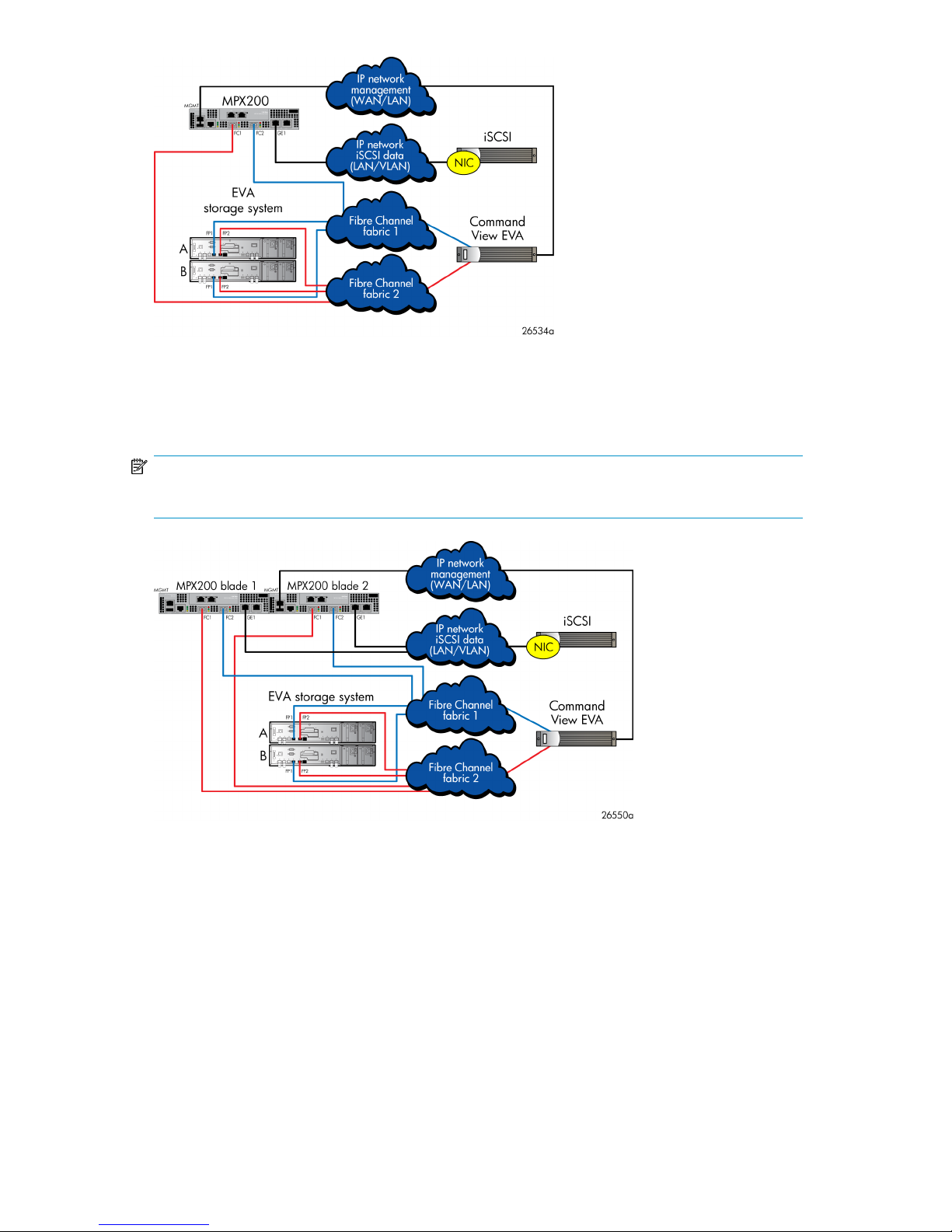
Figure 1 MPX200 single-blade fabric-attached configuration
.
Figure 2 illustrates an MPX200 dual-blade fabric-attached configuration. This configuration provides
high availability with failover between blades.
NOTE:
A dual-blade configuration may require reconfiguration of device mappings.
Figure 2 MPX200 dual-blade fabric-attached configuration
.
Figure 3 illustrates a multi-EVA configuration with connectivity for up to four EVA storage systems from
a single MPX200 blade.
MPX200 Multifunction Router User Guide 19
Page 20
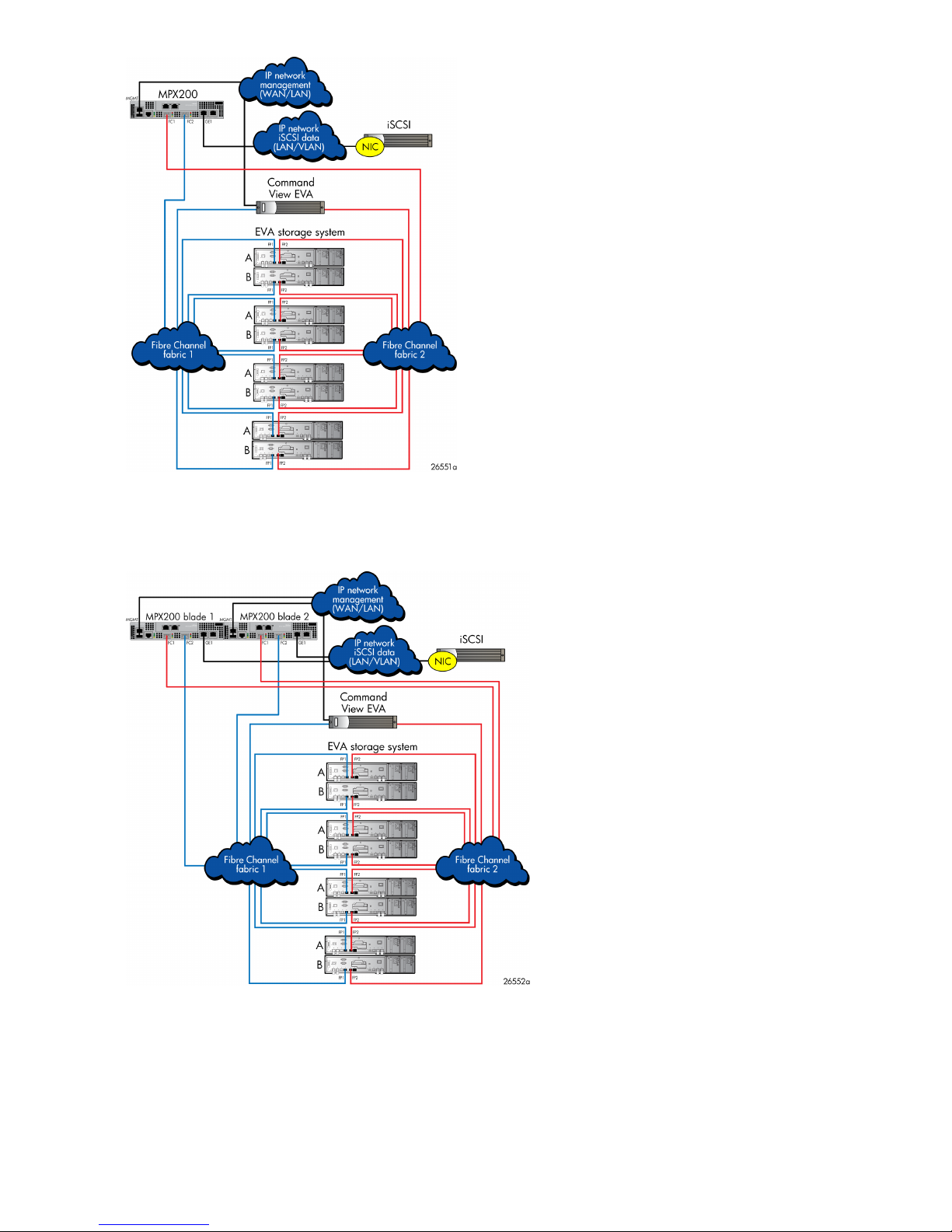
Figure 3 MPX200 single-blade multi-EVA configuration
.
Figure 4 illustrates a multi-EVA configuration with connectivity for up to four EVA storage systems from
dual MPX200 blades. This configuration provides high availability with failover between blades.
Figure 4 MPX200 dual-blade multi-EVA configuration
.
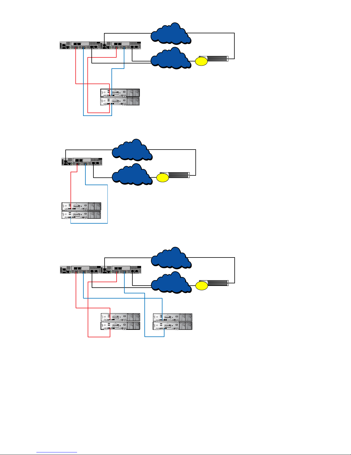
Figure 5, Figure 6, and Figure 7 illustrate EVA direct connect configurations.
MPX200 Multifunction Router overview20
Page 21
GE1 GE2
IOIOI
FC1 FC2MGMT
GE4
GE3
HP StorageWorks
MPX200
1 GbE Blade
MPX200 Multifunction Router
EVA storage system
26639a
GE1
MGMT
IP network
management
(WAN/LAN)
iSCSI
B
A
FC1 FC2
FP1 FP2
FP2
FP1
NIC
MPX200 blade 2
GE1 GE2
IOIOI
FC1 FC2MGMT
GE4
GE3
HP StorageWorks
MPX200
1 GbE Blade
MPX200 Multifunction Router
GE1
MGMT
FC1 FC2
MPX200 blade 1
IP network
iSCSI data
(LAN/VLAN)
Figure 5 MPX200 dual-blade direct connect to one EVA configuration
GE1 GE2
IOIOI
FC1 FC2MGMT
GE4
GE3
HP StorageWorks
MPX200
1 GbE Blade
MPX200 Multifunction Router
EVA
storage system
26640a
GE1
MGMT
IP network
management
(WAN/LAN)
IP network
iSCSI data
(LAN/VLAN)
iSCSI
B
A
FC1 FC2
FP1 FP2
FP2
FP1
NIC
MPX200
GE1 GE2
IOIOI
FC1 FC2MGMT
GE4
GE3
HP StorageWorks
MPX200
1 GbE Blade
MPX200 Multifunction Router
EVA
storage system
26641a
GE1
MGMT
IP network
management
(WAN/LAN)
iSCSI
B
A
FC1 FC2
FP1 FP2
FP2
FP1
NIC
MPX200 blade 2
GE1 GE2
IOIOI
FC1 FC2MGMT
GE4
GE3
HP StorageWorks
MPX200
1 GbE Blade
MPX200 Multifunction Router
GE1
MGMT
FC1 FC2
MPX200 blade 1
IP network
iSCSI data
(LAN/VLAN)
B
A
FP1 FP2
FP2
FP1
.
Figure 6 MPX200 single-blade direct connect to one EVA configuration
.
Figure 7 MPX200 dual-blade direct connect to two EVA configuration
.
MPX200 configurations for XP24000/20000
An XP storage system can be configured for simultaneous connectivity to iSCSI and FC attached hosts.
Support for iSCSI to an XP storage system is provided through the MPX200 and an existing FC switch
fabric port (fabric-attached).
MPX200 Multifunction Router User Guide 21
Page 22
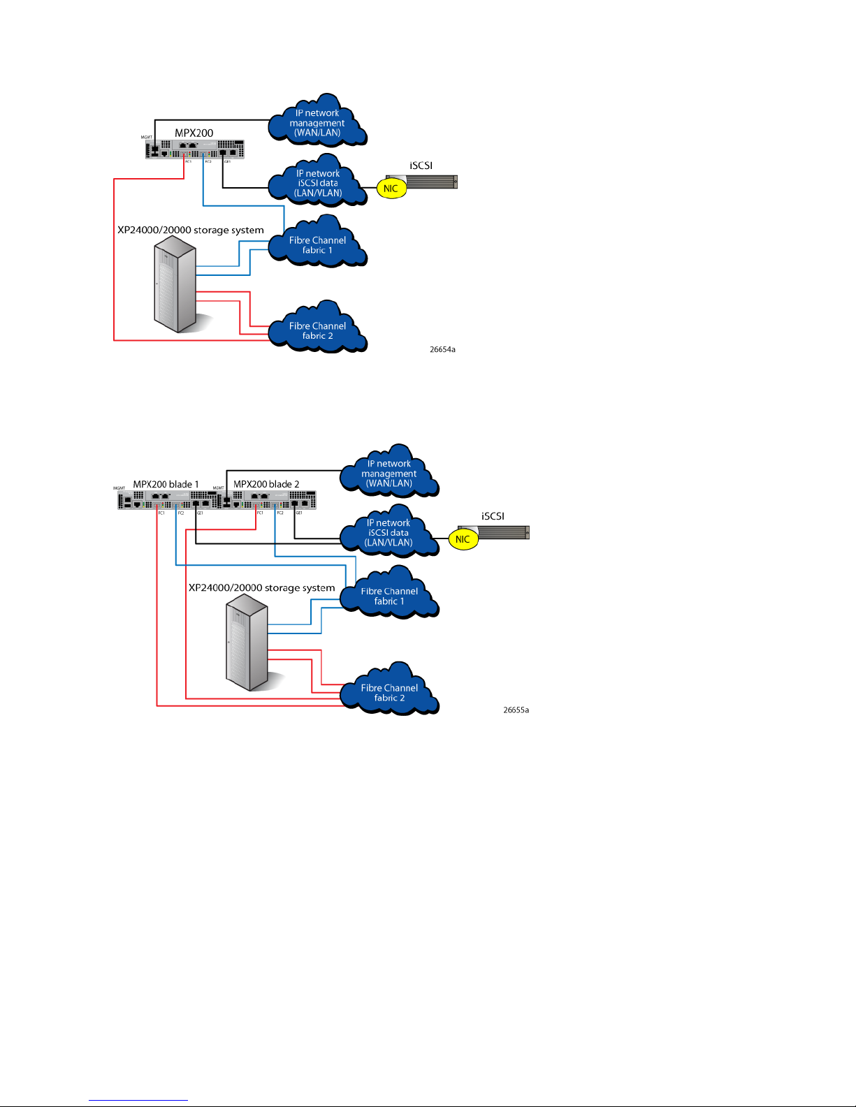
Figure 8 shows an MPX200-XP single-blade fabric-attached configuration. This is the lowest-cost
configuration and is used when high availability for iSCSI hosts is not required.
Figure 8 MPX200-XP single-blade fabric-attached configuration
.
Figure 9 shows an MPX200-XP dual-blade fabric-attached configuration. This configuration provides
high availability with failover between blades.
Figure 9 MPX200-XP dual-blade fabric-attached configuration
.
Figure 10 shows a multi-XP configuration with connectivity for up to four XP storage systems from a
single MPX200 blade.
MPX200 Multifunction Router overview22
Page 23
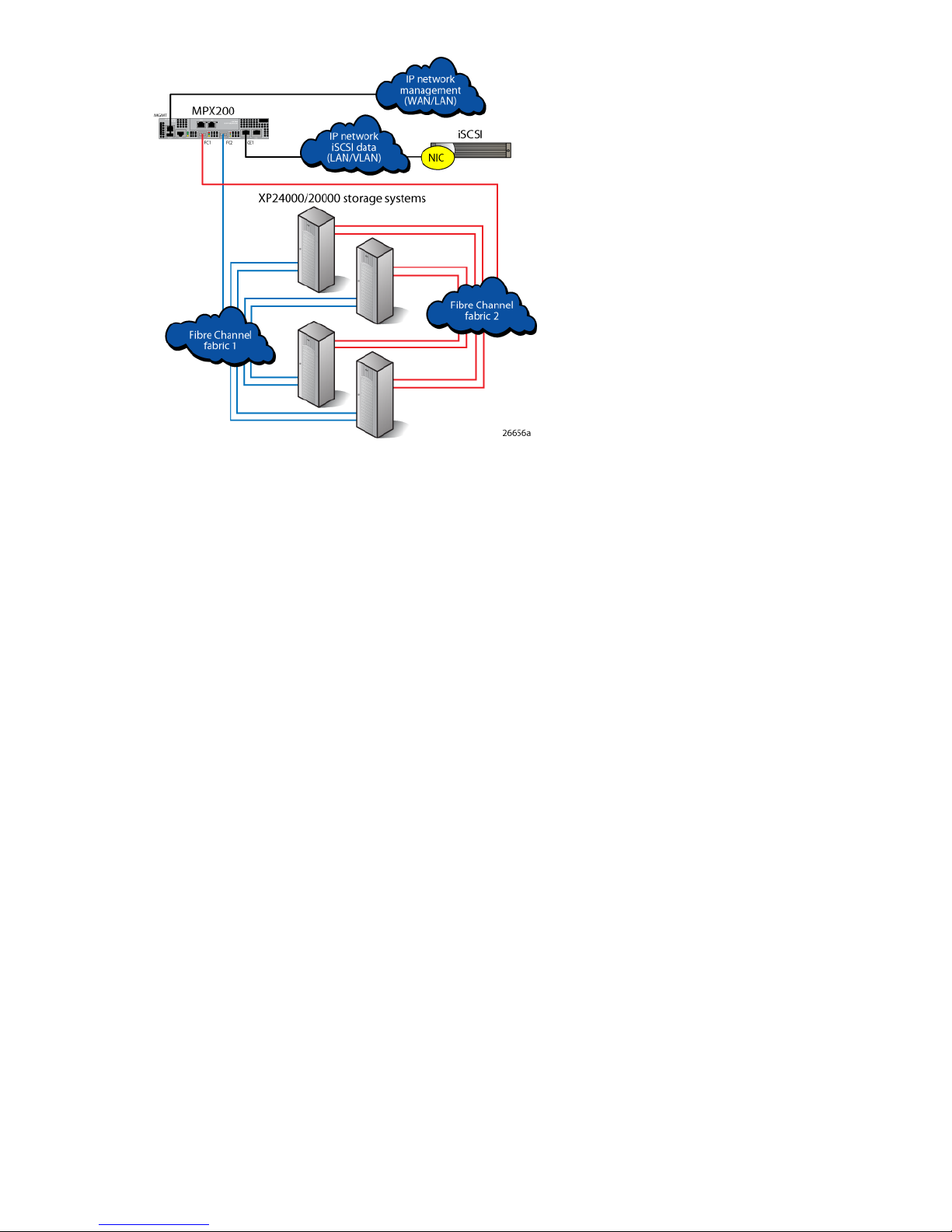
Figure 10 MPX200-XP multi-XP fabric-attached configuration
.
MPX200 Multifunction Router User Guide 23
Page 24

Planning the MPX200 installation
Before installing the MPX200, it is important to define the requirements for iSCSI server connectivity
and MPX200 multifunction usage. You should consider present and future needs as they relate to the
following MPX200 configuration attributes:
• Simultaneous operation
You can configure the MPX200 chassis with a single blade or dual blades to run up to two operations simultaneously per blade as shown in Table 2.
• iSCSI operation
• Dual-blade configurations are for high availability
• Total number of initiators
• Number of paths required per initiator
• Use of Internet Storage Name Service (iSNS)
• Use of iSCSI ports
• Load balancing
• 10-GbE initiators
Table 2 MPX200 blade configurations
Dual-blade chassis (blade1/blade2)Single blade chassis (blade1/blade2)
iSCSI/empty
iSCSI-FCIP/empty
iSCSI-DMS/empty
FCIP/empty
DMS/empty
1
Dual-blade iSCSI configurations are always configured for high availability.
2
Dual-blade FCIP configurations can be configured for separate operation or high availability.
3
Dual-blade DMS (data migration services) configurations are always configured for separate operation.
iSCSI/iSCSI
iSCSI-FCIP/iSCSI-FCIP
iSCSI-DMS/iSCSI-DMS
FCIP/FCIP
DMS/DMS
iSCSI-DMS/iSCSI-FCIP
iSCSI-FCIP/iSCSI-DMS
1
1
1
2
3
1
1
NOTE:
For more information on data migration, see the
Data Migration Solution Guide
.
HP StorageWorks MPX200 Multifunction Router
Table 3 describes the MPX200 supported configuration maximums for ports, blades, and chassis.
MPX200 Multifunction Router overview24
Page 25

Table 3 MPX200 supported configuration maximums
iSCSI connections, 10-GbE model
1
For mixed-blade chassis configurations that include one 1-GbE blade and one 10-GbE blade, the supported maximums are
the 1-GbE values.
2
10-GbE ports only
3
For iSCSI connectivity
Total number of initiators
You can configure the MPX200 with a single blade or with two (redundant) blades. When using two
blades, the initiator is registered in both blades for consistency, whether or not you intend to access
both blades.
2,048
N/ATargets
Per bladePer portConfiguration parameter
2
Up to 4 EVAs
Per chassis (2 blades1)
2,0481,024256iSCSI connections, 1-GbE model
4,0962,048
300300N/AInitiators, 1-GbE model
600600N/AInitiators, 10-GbE model
4,0964,096N/ALUNs, 1-GbE model
4,0964,096N/ALUNs, 10-GbE model
3
Up to 4 EVAs
3
Number of paths required per initiator
After establishing the number of initiators, determine how many paths are required by each. The
number of connections per blade is finite, and every initiator login constitutes a connection to the
MPX200. In a multipath environment, HP recommends a minimum of one connection per blade;
high-performance applications may require up to four connections per blade (a total of eight).
Use of iSNS
The MPX200 presents one iSCSI target for each virtual port group (VPG) (a total of four). Each initiator,
therefore, discovers four times the number of FC targets. HP recommends that you use iSNS to present
to the initiator only the required iSCSI targets.
Use of iSCSI ports
When configuring the MPX200 for iSCSI, there are four available iSCSI ports per blade. For high
performance and maximum initiator connectivity, HP recommends that you use all available ports.
Balancing the load
HP recommends that you use all iSCSI ports for both 1-GbE and 10-GbE blades. If multiple 1-GbE
initiators are required, ensure that logins are spread across all 1-GbE ports. For 10-GbE blades, you
can place a higher number of initiators on the 10-GbE ports than on the 1-GbE ports.
MPX200 Multifunction Router User Guide 25
Page 26

Because iSCSI and data migration traffic can share the same FC ports, it is prudent to understand
how each function effects the other during I/O operation. The use of bandwidth throttling for data
migration or MPIO for iSCSI provides a mechanism to allocate FC bandwidth to each function.
10-GbE initiators
HP recommends that you map servers with 10-GbE NICs for login to the 10-GbE ports on the MPX200.
CHAP security
You can configure the Challenge Handshake Authentication Protocol (CHAP) on the MPX200. CHAP
is a security protocol that supports the bidirectional (mutual) authentication option and the one-way
(target) authentication option. The target MPX200 can have a unique password for the one-way CHAP
option. The initiator can have a unique password for the bidirectional CHAP option with the target
MPX200. See the CHAP information in Chapter 5.
MPX200 Multifunction Router overview26
Page 27

2 Installing the MPX200
This chapter describes how to rack mount the MPX200.
WARNING!
• Mount the MPX200 in the rack so that the weight is evenly distributed. An unevenly loaded rack
can become unstable, possibly resulting in equipment damage or personal injury.
• This product is supplied with a 3 wire cable and plug for the user's safety. Use this power cable
in conjunction with a properly grounded outlet to avoid electrical shock. An electrical outlet that
is not correctly wired could place hazardous voltage on metal parts of the switch chassis. It is the
responsibility of the customer to ensure the outlet is correctly wired and grounded to prevent
electrical shock.
• If the chassis is installed in a closed or multi-rack assembly, the operating temperature of the rack
environment may be greater than the ambient temperature. Be sure to install the chassis in an
environment that is compatible with the maximum ambient rated temperature.
MPX200 components
Figure 11 shows the MPX200 components.
MPX200 Multifunction Router User Guide 27
Page 28
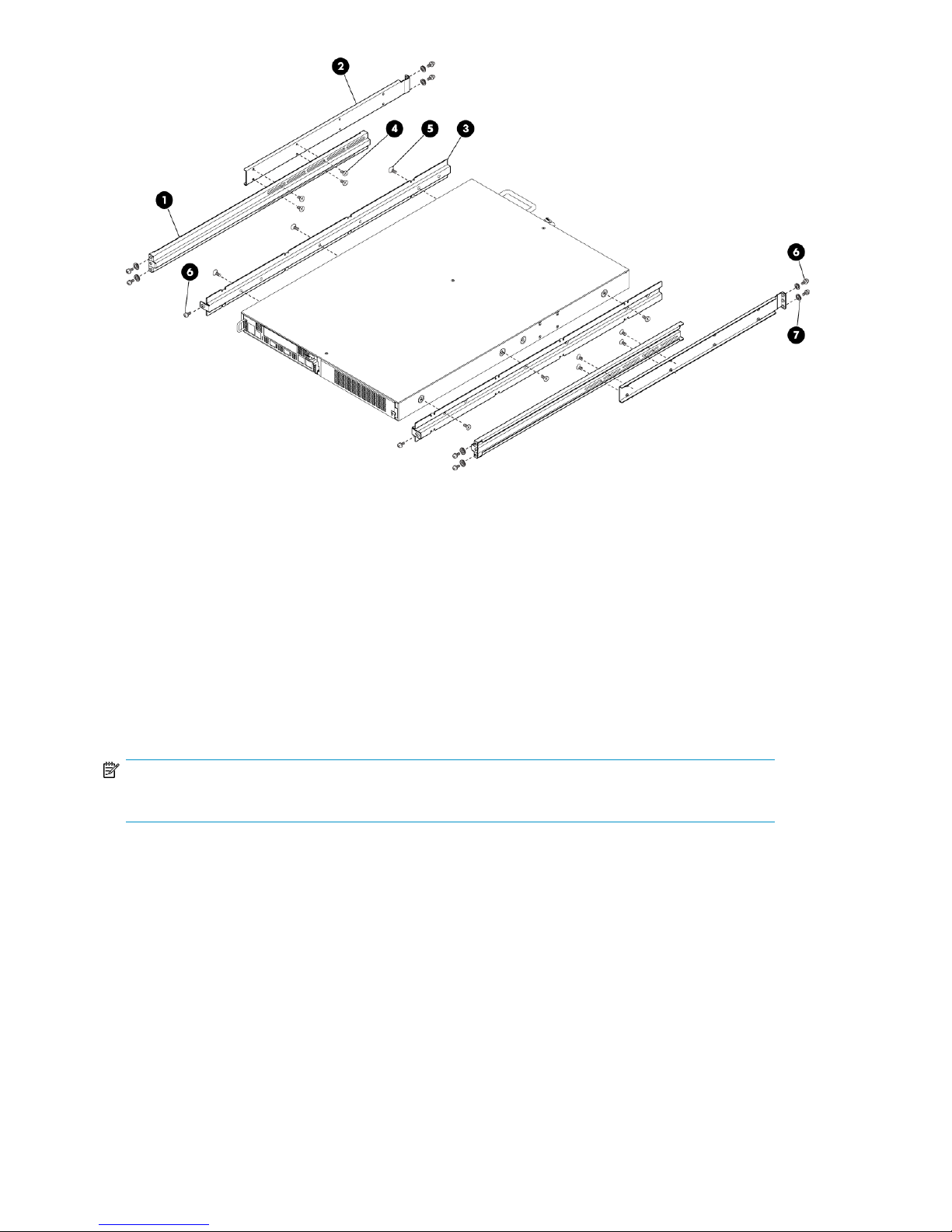
7. Washer, centering (10); for use on racks
with square holes only
Figure 11 MPX200 components
.
Rack mounting the MPX200
NOTE:
Use a crosshead screwdriver to perform the rack mount procedure.
To rack mount the MPX200:
2. Rack rail, outer (2)1. Rack rail, inner (2)
4. Screw, flathead, 6–32 x 1/4 in. (8)3. Chassis rail (2)
6. Screw, panhead, 10–32 x 3/8 in. (10)5. Screw, flathead, 10–32 x 1/4 in. (6)
Installing the MPX20028
Page 29
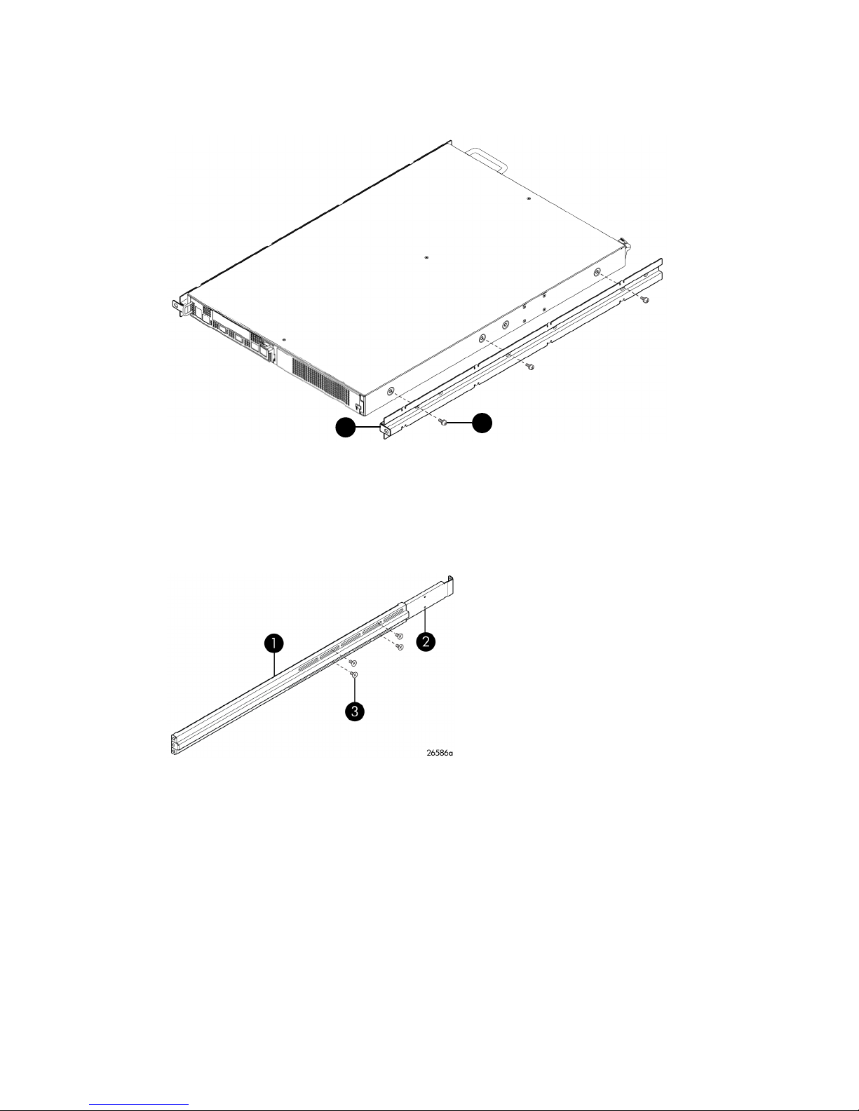
1. Attach the two chassis rails to the MPX200 chassis using three 10-32 x 1/4 in. screws for each
26592b
1
2
rail. Make sure that the end with the flange is facing the rear of the chassis (Figure 12).
The MPX200 has multiple mounting holes to allow for adjustable setback. Secure the chassis rails
in the desired position if additional room is needed.
2. Screws, flathead, 10-32 x 1/4 in.1. Chassis rail
Figure 12 Chassis rails
.
2. Assemble the front and rear rack rails; secure them loosely using four 6-32 x 1/4 in. screws
(Figure 13).
2. Front rack rail1. Rear rack rail
3. Screw, flathead, 6-32 x 1/4 in.
Figure 13 Rack rails
.
MPX200 Multifunction Router User Guide 29
Page 30
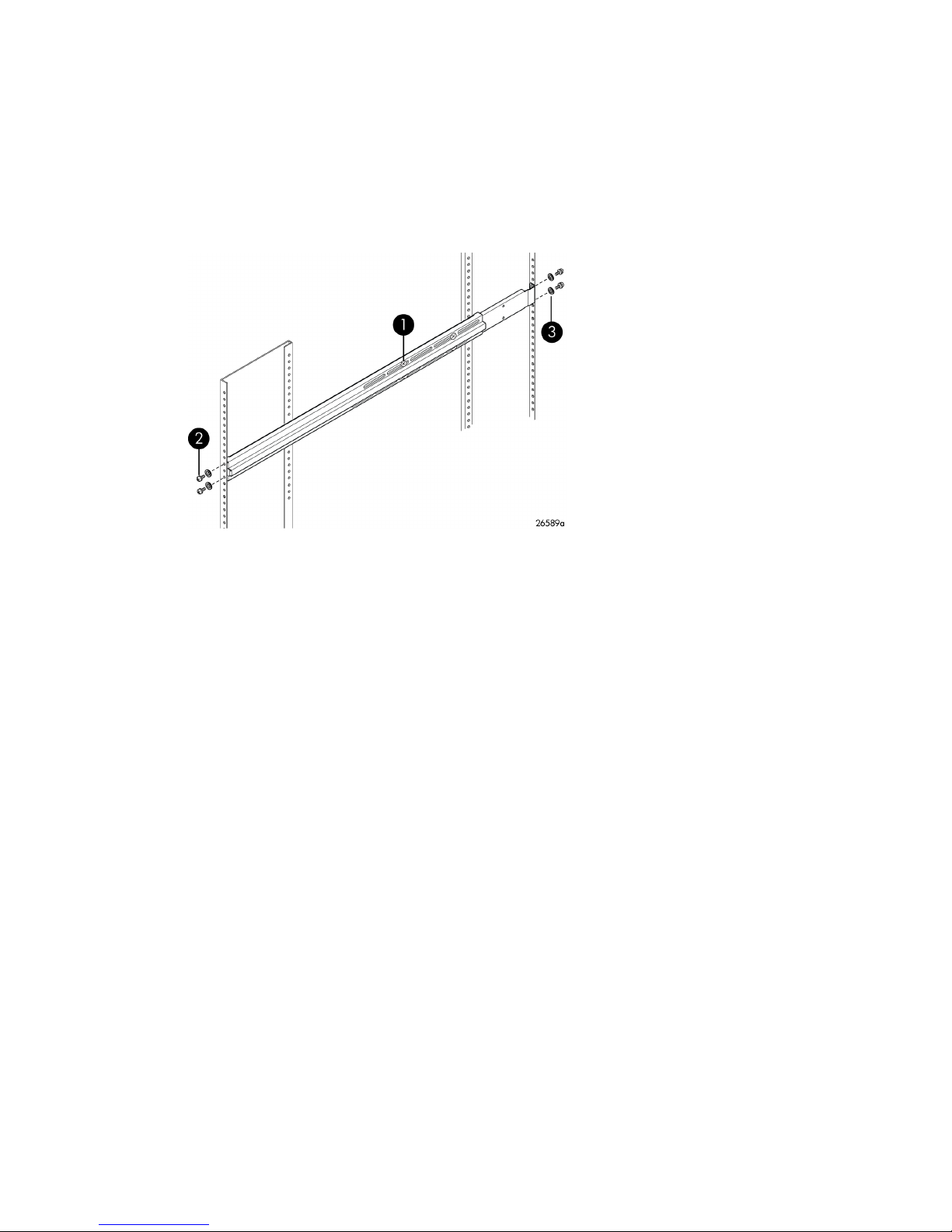
3. Install the rails in the rack.
There are two inner rails and two outer rails. Slide each inner rail into the corresponding outer
rail to create a complete rack rail.
a. Extend the rack rails to fit the inner dimensions of the rack. The rail flanges on both ends fit
inside the rack.
b. Make sure the inner rail is toward the front of the rack.
c. Fasten the rail flanges to the rack on both ends using two 10-32 x 3/8 in. screws in the
upper and lower holes (Figure 14).
3. Washer
Figure 14 Inner rack view
.
2. Screw, panhead, 10-32 x 3/8 in.1. Screw, flathead, 6-32 x 1/4 in.
Installing the MPX20030
Page 31

4. Install the chassis in the rack:
1
26588b
1
a. Starting from the back of the rack, slide the MPX200 chassis and rail assembly into the rack
rails.
b. Fasten the chassis to the rack using two 10-32 x 3/8 in. screws in the middle hole on each
rail flange (Figure 15).
1. Screws, panhead, 10-32 x 3/8 in.
Figure 15 Rear view
.
MPX200 Multifunction Router User Guide 31
Page 32

5. Route the power cord:
26591b
1
a. Starting from the front of the rack, connect the power cord to the MPX200.
b. For the left blade, route the cord by following the gap between the chassis and the chassis
rail (see Figure 16).
c. Repeat for the right blade.
NOTE:
The right blade requires the power cord to extend approximately 12 in. (30 cm) beyond
the front edge, due to the positioning of the socket on the PCM.
1. Power cord
Figure 16 Power cord
.
Installing the MPX20032
Page 33

6. Install the HP StorageWorks MPX200 bezel:
a. Remove the four 10-32 x 3/8 in. screws that secure the rack rails to the front of the rack.
b. Position the bezel support plate in front of the MPX200 chassis, with the arrows pointing
up.
c. Replace the four 10-32 x 3/8 in. screws, two on each side of the bezel support plate.
d. Install the bezel by pushing it through the white pop-in tabs on the bezel support plate (Figure
17).
2. Bezel mount bracket1. Screw, panhead, 10-32 x 3/8 in.
Figure 17 Bezel view
.
4. Bezel3. Bracket arrows
MPX200 Multifunction Router User Guide 33
Page 34

Installing the MPX20034
Page 35

3 Managing the MPX200 using HP
Command View EVA
This chapter provides instructions for setting up the MPX200 management port, Fibre Channel zoning,
HP Command View EVA discovery, setting up the iSCSI IP ports, and setting the date and time.
NOTE:
FCIP functionality is not completely configured using HP Command View EVA. For configuration
requirements, see Chapter 6 on page 117.
Setting up the MPX200 management port
Most management functions have been built into HP Command View EVA. In some cases, access to
the MPX200 CLI is required.
You connect to the CLI through one of the following:
• RS-232 serial port (115200/8/n/1)
• Telnet
• Secure Shell (SSH)
By default, the management port obtains a Dynamic Host Configuration Protocol (DHCP) address. If
the management port cannot obtain a DHCP address, you must set a static IP address.
Fibre Channel zoning
Because the MPX200 can be a fabric-connected device, it is important to understand the zoning
requirements.
Open zoning
When using an open zone configuration, each FC port on each MPX200 must be connected to a
separate fabric (see Figure 18 on page 36).
MPX200 Multifunction Router User Guide 35
Page 36

Figure 18 Open zone configuration
.
Fibre Channel switch-based zoning
Each FC port on the MPX200 uses N_Port ID Virtualization (NPIV) to create a total of four unique,
virtual world wide node names (WWNNs) per physical FC port. To create proper zoning, you must
understand the use of VPGs. A VPG consists of a WWNN from each of the four physical FC ports.
This allows presentation for up to 1,024 LUNs from a single EVA or XP array.
Place an array target port in the same zone as one of the VPG ports (see Figure 19 on page 37).
This ensures a single path to the FC port on the router blade and gives you more control of load
balancing through the router.
Managing the MPX200 using HP Command View EVA36
Page 37

Figure 19 Fibre Channel zone configuration
.
HP Command View EVA discovery
Once the management port IP address is set and the router FC ports are visible to the EVA, you can
perform the MPX200 discovery. You discover the MPX200 iSCSI controllers using the Discover iSCSI
Devices button or the Add iSCSI Device button (see Figure 20).
Figure 20 iSCSI devices folder properties
.
MPX200 Multifunction Router User Guide 37
Page 38

NOTE:
HP recommends that you set a static IP address on the management port to ensure connectivity.
After the discovery is complete, the MPX200s appear in the iSCSI Devices folder as iSCSI Controller
01 and iSCSI Controller 02. The four iSCSI MPX200 hosts appear in the Hosts folder (see Figure 21).
The ports associated with each host consist of the VPGs from each blade.
Figure 21 Host properties
.
In the IPv4 or IPv6 box, select Static and set the management port IP address.
Figure 22 shows the Management Port tab on the iSCSI Controller Properties page.
Managing the MPX200 using HP Command View EVA38
Page 39

Figure 22 iSCSI controller properties: Mgmt Port tab
.
Setting up the iSCSI IP ports
Each iSCSI IP port must have an IP address—IPv4, IPv6, or both. Set the IP address on the IP Ports
tab on the iSCSI Controller Properties page (see Figure 23).
NOTE:
A target portal is created for each IP address that you set.
MPX200 Multifunction Router User Guide 39
Page 40

Figure 23 iSCSI controller properties: IP Ports tab
.
Setting the date and time on the MPX200
Setting the date and time on the MPX200 ensures the synchronization of events and assists in
troubleshooting. You have three options for setting the date and time (see Figure 24).
NOTE:
HP recommends using the Network Time Protocol (NTP) settings, if available on your network. This
provides redundancy through multiple time servers.
Managing the MPX200 using HP Command View EVA40
Page 41

Figure 24 Set iSCSI controller time
.
Code load
NOTE:
HP recommends that you load the latest MPX200 firmware. Check http://www.hp.com/go/mpx200
for updates.
You load the firmware from the Code Load page for the iSCSI controller. Firmware is loaded for the
selected controller only; for a dual-blade configuration, you must perform this procedure for each
blade.
1. Select the desired iSCSI controller.
2. Click the Code Load button.
3. Browse to the firmware file.
4. Click the Next Step button.
5. Click the Finish button.
6. In the dialog box, enter yes, and then click the Update button.
The MPX200 reboots upon successful load of the firmware.
MPX200 Multifunction Router User Guide 41
Page 42

Figure 25 Code Load page for the iSCSI controller
.
Shutting down and restarting the MPX200
If you need to restart the MPX200, click the Restart button (see Figure 26). If you need to shut down
the MPX200, click the Power down button (see Figure 26).
Figure 26 iSCSI controller shutdown options
.
Saving or restoring the MPX200 configuration
After initial setup of the MPX200, it is a good practice to save the configuration. The FRU Save function
allows you to save the configuration to a file that can be used later as a restoration point. The FRU
Managing the MPX200 using HP Command View EVA42
Page 43

Restore function allows you to restore the configuration to the point when the configuration was last
saved, which is especially important for single-blade configurations.
NOTE:
A Restore action reboots the blade.
In a dual-blade configuration, a copy of the configuration for each router is kept on the peer. If you
add a new blade, the configuration of the peer blade is copied to the new blade and is ready for
use immediately; no reconfiguration is required.
To save or restore the MPX200 configuration:
1. Select the desired blade.
2. Click the Set Options button.
3. Click the Save Configuration button.
4. Select the configuration method (see Figure 27).
Figure 27 iSCSI controller configuration selection
.
Locating the MPX200
A flashing blue LED in the center of the blade indicates that the locating beacon is on.
NOTE:
The beacon turns off after 15 minutes.
MPX200 Multifunction Router User Guide 43
Page 44

2. System power LED1. Input fault LED
4. 1–GbE iSCSI ports3. Heartbeat LED
6. Maintenance button5. 1–GbE iSCSI ports
8. UID beacon (LED) blue7. 8–Gb/s FC ports
10. Management port 10/100/1000 Ethernet9. RS-232 port
Figure 28 Blue LED locating beacon
.
To enable or disable the locating beacon:
1. Select the desired iSCSI controller.
2. Click the Locate button.
3. Click the Locate ON or Locate OFF button (Figure 29).
Figure 29 Locate hardware device
.
Removing an iSCSI controller
Before you remove an iSCSI controller permanently, ensure that all virtual disk presentations have
been removed.
To remove an iSCSI controller:
1. Select the desired iSCSI controller.
2. Click the Set Options button.
3. Click the Remove controller button (see Figure 30).
4. Click the Remove button on the dialog box.
Managing the MPX200 using HP Command View EVA44
Page 45

Figure 30 iSCSI controller options: Remove controller
.
MPX200 Multifunction Router User Guide 45
Page 46

Managing the MPX200 using HP Command View EVA46
Page 47

4 Managing the MPX200 for XP
24000/20000
Setting up the MPX200 management port
Access to the MPX200 CLI is required for initial setup. Connect to the CLI through one of the following:
• RS-232 serial port (115200/8/n/1)
• Telnet
• Secure Shell (SSH)
By default, the management port obtains a Dynamic Host Configuration Protocol (DHCP) address. If
the management port cannot obtain a DHCP address, you must set a static IP address. Static IP
addresses are highly recommended to retain connectivity.
Once connected, select the desired blade to manage by using the blade <1 or 2> command (see
Figure 31).
Figure 31 Use the blade # command
.
Use the admin start command to change settings (see Figure 32).
Figure 32 The admin start command
.
MPX200 Multifunction Router User Guide 47
Page 48

Use the set mgmt command to setup the management port IP address (see Figure 33).
Figure 33 The set mgmt command.
.
Set up the iSCSI ports
The iSCSI ports require an IP address. Use the set iscsi command (see Figure 34).
Figure 34 The set iscsi command
.
Fibre Channel zoning
See “Fibre Channel zoning” on page 35 and “Fibre Channel switch-based zoning” on page 36 for
zoning information.
World Wide Names used in zoning can be found in the MPX200 using the show vpgroups command
(see Figure 35).
Managing the MPX200 for XP 24000/2000048
Page 49

Figure 35 The show vpgroup command
.
LUN management
LUN masking for MPX200 connectivity to XP is accomplished by executing the following procedure.
The MPX200 is treated as if it were a Windows FC host to the XP.
MPX200 Multifunction Router User Guide 49
Page 50

1. To properly setup LUN masking, create a group that includes the WWNs from a single Virtual
Port Group (VPG).
To identify which WWNs belong to a VPG see the fourth bit (circled in the Figure 36). You can
create up to four groups, each containing WWNs from each VPG from each MPX200 blade.
LUNs can be created and assigned to the groups at this time.
Figure 36 LUN management window
.
2. Install the Microsoft iSCSI Initiator software. For Windows Server 2008, the iSCSI initiator is
included with the operating system.
For Windows Server 2003, you must install the iSCSI initiator. For Windows Server 2003, the
Microsoft iSCSI initiator installation presents an option for installing MPIO using the Microsoft
generic DSM (Microsoft MPIO Multipathing Support for iSCSI check box). For Windows Server
2008, MPIO is installed separately as a feature.
3. See “Setting up the iSCSI initiator” on page 60 to set up the Windows host and register the IQN
name.
4. Install and run the mpx Manager.
Managing the MPX200 for XP 24000/2000050
Page 51

5. Start the Presentation Wizard by selecting Wizards from the menu.
The LUN Presentation Wizard will display the XP target ports (see Figure 37).
Figure 37 LUN Selection window
.
6. Expand the desired ports and select the same LUN from each (see Figure 38).
Figure 38 Expanded ports
.
MPX200 Multifunction Router User Guide 51
Page 52

7. Select the initiator and finish (see Figure 39).
Figure 39 Select the Initiators
.
8. Follow the steps beginning with “Step 3” on page 65 to log in to the target.
Managing the MPX200 for XP 24000/2000052
Page 53

5 MPX200 iSCSI configuration rules and
guidelines
This chapter describes the iSCSI configuration rules and guidelines for the MPX200.
iSCSI rules and supported maximums
The MPX200 chassis can be configured with one or two blades. Dual-blade configurations provide
for high availability with failover between blades, and are supported as redundant pairs only.
iSCSI-connected servers can be configured for access to one or both blades.
NOTE:
In the event of a failover between blades, servers with single-blade connectivity to a failed blade will
no longer have connectivity to the MPX200.
Table 4 lists the supported maximums.
MPX200 Multifunction Router User Guide 53
Page 54

Table 4 Supported MPX200 iSCSI maximums
Description
Hardware
MPX200 iSCSI port connections
Configuration parameter
Total number of iSCSI initiators
1
For mixed-blade chassis configurations that include one 1-GbE blade and one 10-GbE blade, the maximums supported are
the 1-GbE blade values.
Maximum per MPX200 solution
4 total (any combination)EVA and/or XP24000/20000 storage systems
One chassis with up to 2 bladesMPX200
See “Planning the MPX200 installa-
tion” on page 24.
300 per chassis for 1 GbE (1 or 2 blades)
600 per chassis for 10 GbE (1 or 2 blades)
4,096 per chassis, 1,024 per EVA or XPTotal number of iSCSI logical unit numbers (LUNs)
1,024 per blade, 2,048 per chassisiSCSI connections, 1 GbE
2,048 per blade, 4,096 per chassisiSCSI connections, 10 GbE
EVA storage system rules and guidelines
1
The MPX200 is supported with the following EVA storage systems:
• EVA4400/4400 with embedded switch
• EVA4000/4100/6000/6100/8000/8100
• EVA6400/8400
All MPX200 configurations must follow these EVA connectivity rules:
• All MPX200 Fibre Channel connections are supported for fabric–connect or direct-connect config-
urations.
• Each EVA storage system can connect to a maximum of one MPX200 chassis (two blades).
• Each EVA controller host port can connect to a maximum of two MPX200 Fibre Channel ports.
• A maximum of one MPX200 chassis (two blades) can be zoned with up to four EVA storage systems.
• An EVA storage system can present LUNs to iSCSI initiators and Fibre Channel hosts concurrently.
HP Command View EVA management rules and guidelines
The HP Command View EVA implementation for the MPX200 supports management of up to four
EVA storage systems concurrently, and provides the equivalent functionality for both iSCSI and Fibre
Channel connected servers. All MPX200 management functions are integrated in HP Command View
EVA.
IMPORTANT:
The MPX200 requires a specific controlled release of HP Command View EVA. For more information
and to receive the supported HP Command View EVA version, contact your HP service representative.
MPX200 iSCSI configuration rules and guidelines54
Page 55

The HP Command View EVA management rules and guidelines follow:
• Requires HP Command View EVA 9.1.1 or later for array-based and server-based management.
• A maximum of one MPX200 chassis (two blades) can be discovered by an EVA storage system.
• HP Command View EVA manages the MPX200 out of band (IP) through the MPX200 management
IP port. The HP Command View EVA application server must be on the same IP network as the
MPX200 management IP port.
• The MPX200 iSCSI initiator and iSCSI LUN masking information resides in the MPX200, not in
the HP Command View EVA database.
• The default iSCSI initiator EVA host-mode setting is Microsoft Windows. The iSCSI initiator host-
mode setting for Apple Mac OS X, Linux, Oracle Solaris, VMware, and Windows 2008 is configured with HP Command View EVA.
NOTE:
Communication between HP Command View EVA and the MPX200 is not secured by the
communication protocol. If unsecured communication is a concern, HP recommends using a confined
or secured IP network in the data center.
EVA storage system software
EVA storage system software supported for Fibre Channel hosts, such as HP StorageWorks Continuous
Access, Business Copy, Storage System Scripting Utility (SSSU), and Replication Solutions Manager
(RSM), are supported with the MPX200 for EVA LUNs that have been presented to iSCSI initiators.
This section describes restrictions for iSCSI hosts using the MPX200.
Features supported for iSCSI hosts
The following Business Copy features are supported for iSCSI hosts:
• LUN snapshots presented to iSCSI hosts
• LUN snapclones (normal or 3-phase) presented to iSCSI hosts
• Instant restore from a snapclone to the original source
• Ability of iSCSI hosts to access and write to EVA snapshots and snapclones
• Use of HP Command View EVA, SSSU, or RSM to create snapshots manually or automatically on
a schedule
• CLI support to enter replication commands from iSCSI hosts
Features not supported for iSCSI hosts
LUNs that are presented to iSCSI hosts through the MPX200, and that require a host agent on the
iSCSI initiator, do not support advanced replication features because there are no iSCSI replication
host agents available. The following features are not supported for iSCSI hosts:
• Mounting and unmounting LUNs through a host agent, which must be performed manually
• Accessing the host view of storage (for example, viewing an F drive from a host)
• Deploying host agents to allow users to launch a script on the iSCSI host
MPX200 Multifunction Router User Guide 55
Page 56

Table 5 describes support for EVA storage system software when using the MPX200 for iSCSI.
Table 5 Support for EVA storage system software with MPX200 iSCSI
MPX200 iSCSI supportHP StorageWorks product
HP StorageWorks Business Copy
HP StorageWorks Replication Solutions Manager
SSSU
HP StorageWorks Continuous Access EVA
HP StorageWorks Continuous Access EVA with HPsupported FCIP gateways
XP storage system rules and guidelines
The MPX200 is supported with the following XP storage systems:
• XP24000
• XP20000
All MPX200 configurations must follow these connectivity rules:
• When using the MPX200 for iSCSI, MPX200 FC connections must be fabric-attached through an
FC switch.
• Each XP storage system can connect to a maximum of one MPX200 chassis (two blades).
• A maximum of one MPX200 chassis (two blades) can be zoned with up to four XP storage systems.
• XP and EVA storage systems can connect to the same MPX200, The total allowable number of
storage systems is four per MPX200 chassis.
• An XP storage system can present LUNs to iSCSI initiators and FC hosts concurrently.
iSCSI and Fibre Channel hosts are supported.
iSCSI and Fibre Channel hosts and LUN remote replication are supported.
Fibre Channel switch and fabric support
The MPX200 is supported with HP B-series and C-series switch models.
For the latest information on Fibre Channel switch model and firmware support, see the Single Point
of Connectivity Knowledge (SPOCK) at http://www.hp.com/storage/spock. You must sign up for an
HP Passport to enable access.
Operating system and multipath software support
This section describes the MPX200 iSCSI operating system, multipath software, and cluster support.
For the latest information on operating system and multipath software support, see SPOCK at http:/
/www.hp.com/storage/spock. You must sign up for an HP Passport to enable access
Table 6 describes EVA operating system and multipath software support.
Table 6 EVA operating system and multipath software support
EVA storage systemClustersMultipath softwareOperating system
MPX200 iSCSI configuration rules and guidelines56
Page 57

NoneNoneApple Mac OS X
Microsoft Windows
Server 2008, 2003,
Hyper-V
Red Hat Linux, SUSE
Linux
MPIO with HP DSM
MPIO with Microsoft
DSM
MSCS
NoneDevice Mapper
NoneSolaris MPxIOSolaris
NoneVMware MPxIOVMware
Table 7 lists XP24000/20000 operating system and multipath software support.
Table 7 MPX200-XP operating system and multipath support
iSCSI initiator rules and guidelines
This section describes the iSCSI initiator rules and guidelines for Apple Mac OS, Microsoft Windows,
Linux, Solaris, and VMware. General iSCSI initiator rules and guidelines follow:
• iSCSI initiators and MPX200 iSCSI ports can be in different IP subnets. This requires setting the
MPX200 iSCSI gateway feature. For more information, see “MPX200 configuration options for
EVA” on page 18 and Appendix B on page 211.
• Both single-path and multipath initiators are supported on the same MPX200.
• Fibre Channel LUNs and iSCSI LUNs are not supported on the same server.
EVA4400/4400 with embedded switch
EVA4000/4100/6000/6100/8000/8100
EVA6400/8400
XP storage systemMultipath softwareOperating system
XP24000/20000MPIO with Microsoft DSMMicrosoftWindows Server 2008, 2003
Apple Mac OS X iSCSI initiator rules and guidelines
The Apple Mac OS X iSCSI initiator supports the following:
• Power PC and Intel Power Mac G5, Xserve, Mac Pro
• ATTO Technology Mac driver
• iSNS
• CHAP
iSCSI initiator operating system considerations follow:
• Host-mode setting—Apple Mac OS X
• Multipathing—Not supported
Microsoft Windows iSCSI initiator rules and guidelines
The Microsoft Windows iSCSI initiator supports the following:
• Microsoft iSCSI initiator versions 2.08 and 2.07
• Microsoft iSCSI Initiator for Windows 2008, Vista, and Windows 7
• Multipath on MPX200 single-blade or dual-blade configurations
iSCSI initiator operating system considerations follow:
MPX200 Multifunction Router User Guide 57
Page 58

• Host-mode setting—Microsoft Windows 2008 or Windows 2003
• Tcp1323Opts parameter (registry)—Must have a value of DWord=2 under the setting
NOTE:
The Tcp1323Opts parameter is set automatically by the HP StorageWorks MPX200 for Enterprise
Virtual Array Windows software kit, which is available at
http://h18006.www1.hp.com/products/storageworks/evaiscsiconnect/index.html .
CAUTION:
Using the Registry Editor incorrectly can cause serious problems that may require reinstallation of the
operating system. Use Registry Editor at your own risk. Back up the registry before you make any
changes.
Linux iSCSI initiator rules and guidelines
The Linux iSCSI initiator supports the following:
• Red Hat Linux and SUSE Linux
• Multipath using HP Device Mapper
iSCSI initiator operating system considerations follow:
• Host-mode setting—Linux
• NIC bonding—Not supported
Solaris iSCSI initiator rules and guidelines
The Solaris iSCSI initiator supports the following:
• Solaris iSCSI initiator only
• Multipath using MPxIO
• MPxIO Symmetric option only
• MPxIO round-robin
• MPxIO auto-failback
iSCSI initiator operating system considerations follow:
• Host-mode setting–Solaris
• TOE NICs or iSCSI HBA—Not supported
• LUN 0—Not supported
VMware iSCSI initiator rules and guidelines
The VMware iSCSI initiator supports the following:
• Native iSCSI initiator in VMware ESX 4.0/3.5
• Guest OS SCSI controller, LSI Logic and/or Bus Logic (Bus Logic with SUSE Linux only)
• ESX server native multipath solution, based on NIC teaming on the server
• Guest OS boot from an MPX200 iSCSI device
MPX200 iSCSI configuration rules and guidelines58
Page 59

• Virtual Machine File System (VMFS) data stores and raw device mapping for guest OS virtual
machines
• Multi-initiator access to the same LUN via VMFS
• VMware ESX server 4.0/3.5 native multipath solution based on NIC teaming
iSCSI initiator operating system considerations follow:
• Host-mode setting—VMware
• Hardware iSCSI initiator (iSCSI HBA)—Not supported
MPX200 Multifunction Router User Guide 59
Page 60

Supported IP network adapters
For the latest information on IP network adapter support, see the product release notes or SPOCK at
http://www.hp.com/storage/spock. You must sign up for an HP Passport to enable access.
Table 8 lists the IP network adapters supported by the MPX200.
Table 8 Supported IP network adapters
Network interconnectOperating system
All standard GbE NICs/ASICs supported by AppleApple Mac OS X
Microsoft Windows Server 2008,
2003, Hyper-V
Red Hat Linux, SUSE Linux
Solaris
VMware
IP network requirements
HP recommends the following:
• Network protocol: TCP/IP IPv6, IPv4, Ethernet 1,000 Mb/s or 10 GbE
• IP data—LAN/VLAN support with less than 10 ms latency; maximum of two VLANs per port, one
VLAN per protocol
• IP management—LAN/WAN support
• Dedicated IP network for iSCSI data
• Jumbo frames
All standard 1 Gbe or 10 GbE NICs/ASICs and TOE NICs supported by
HP for Windows 2008 and 2003
QLogic iSCSI HBAs
All standard 1 Gbe or 10 GbE NICs/ASICs supported by HP for Linux
QLogic iSCSI HBAs
All standard GbE NICs/ASICs supported by Sun
All standard 1 Gbe or 10 GbE NICs/ASICs supported by HP for VMware
QLogic iSCSI HBAs
NOTE:
If you configure IPv6 on any MPX200 iSCSI port, you must also configure IPv6 on the HP Command
View management server.
Setting up the iSCSI initiator
This section explains how to set up the iSCSI initiator.
Windows Server iSCSI initiator
For Windows Server 2008, the iSCSI initiator is included with the operating system. For Windows
Server 2003, you must install the iSCSI initiator.
MPX200 iSCSI configuration rules and guidelines60
Page 61

1. Install the HP StorageWorks MPX200 iSCSI kit.
a. Start the installer by running Launch.exe. (If you are using a CD-ROM, the installer should
start automatically.)
b. Click Install iSCSI software package (Figure 40).
Figure 40 Installing the Windows Server 2003 kit
.
For Windows Server 2003, the Microsoft iSCSI initiator installation presents an option for
installing MPIO using the Microsoft generic DSM (Microsoft MPIO Multipathing Support for
iSCSI check box). For Windows Server 2008, MPIO is installed separately.
MPX200 Multifunction Router User Guide 61
Page 62

Figure 41 Installation Wizard
.
c. Click the Microsoft iSCSI Initiator icon to open the Control Panel applet.
The iSCSI Initiator Properties window opens.
d. Select the Discovery tab (Figure 42).
Figure 42 iSCSI initiator properties: Discovery tab
.
e. In the Target Portals section, click Add.
A dialog box opens.
f. Enter the iSCSI port IP address.
g. Click OK.
The discovery is complete.
MPX200 iSCSI configuration rules and guidelines62
Page 63

2. In HP Command View EVA, set up the iSCSI host and virtual disks.
a. Click the EVA Storage Systems icon to start the iSCSI storage presentation.
In Figure 43, MPX200-XL is the target EVA storage system.
Figure 43 Adding a host
.
b. Select the Hosts folder.
c. Click Add host to create an iSCSI initiator host.
A dialog box opens.
• Enter a name for the initiator host in the Name box.
• Select iSCSI as the Type.
• Select the initiator iSCSI qualified name (IQN) from the iSCSI node name list.
• Select an operating system from the Operating System list.
d. Create a virtual disk and present it to the host you created in Step 2.c. Note the circled
number in the target IQN; it is referenced during initiator login. See Figure 44 and Figure
45.
MPX200 Multifunction Router User Guide 63
Page 64

Figure 44 Virtual disk properties
.
Figure 45 Host details
.
MPX200 iSCSI configuration rules and guidelines64
Page 65

3. Set up the iSCSI disk on the iSCSI initiator.
a. Open the iSCSI initiator Control Panel applet.
b. Select the Targets tab and then click the Refresh button to see the available targets (see
Figure 46). The status should be Inactive.
Figure 46 Targets tab
.
c. Select the target IQN noted in Step 2.d, and then click Log On.
A dialog box opens.
d. Configure the target IQN.
• Select the Automatically check box to restore this connection when the system boots.
• Select the Multipathing check box to enable MPIO. The target status is Connected when
logged in.
NOTE:
HP recommends using the Advanced button to choose the Local Adapter, Source IP,
and Target Portal. The Target Portal IP Address is the iSCSI port that this initiator
connection is defined.
e. Depending on the operating system, open Server Manager or Computer Management.
f. Select Disk Management.
MPX200 Multifunction Router User Guide 65
Page 66

g. Select Action > Rescan Disks. Verify that the newly assigned disk is listed; if not, you may
h. Format and partition the disk to prepare it for use.
Multipathing
Microsoft MPIO includes support for redundant paths to send I/O from the initiator to the target. For
Windows Server 2008, MPIO is a separate feature that must be installed separately. Microsoft iSCSI
Software Initiator 2.x includes MPIO and must be selected for installation. Setting up redundant paths
properly ensures high availability of the target disk. Ideally, the paths would use separate network
interface cards (NICs) and a separate network infrastructure (cables, switches, and MPX200 blades).
HP recommends using separate target ports.
Microsoft MPIO allows the initiator to log in to multiple sessions to the same target and aggregate
the duplicate devices into a single device exposed to Windows. Each session to the target can be
established using different NICs, network infrastructure, and target ports. If one session fails, another
session can continue processing I/O without interrupting the application. The iSCSI target must support
multiple sessions to the same target. The Microsoft iSCSI MPIO DSM supports a set of load-balance
policies that determine how I/O is allocated among sessions. With Microsoft MPIO, the load-balance
policies apply to each LUN individually.
The Microsoft iSCSI DSM 2.x assumes that all targets are active/active and can handle I/O on any
path at any time. There is no mechanism in the iSCSI protocol to determine whether a target is
active/active or active/passive; therefore, the MPX200 supports only multipath configurations with
the EVA with active/active support. For more information, see the following:
need to reboot.
http://www.microsoft.com/WindowsServer2003/technologies/storage/mpio/default.mspx
http://www.microsoft.com/WindowsServer2003/technologies/storage/mpio/faq.mspx
http://download.microsoft.com/download/3/0/4/304083f1-11e7-44d9-92b9-2f3cdbf01048/
mpio.doc
Table 9 details the differences between Windows Server 2008 and Windows Server 2003.
Table 9 Differences between Windows Server 2008 and Windows Server 2003
Windows Server 2003Windows Server 2008
Must be installed separatelyIncluded with operating systemiSCSI initiator
Included with iSCSI initiatorMust be installed separatelyMPIO
Table 10 lists the supported MPIO options for the MPX200.
Table 10 MPIO options for the MPX200
Windows Server 2003Windows Server 2008Multipath support
HP MPIO Full Featured
DSM for EVA (preferred)
SupportedSupported
SupportedSupportedMicrosoft generic DSM
MPX200 iSCSI configuration rules and guidelines66
Page 67

Installing the MPIO feature for Windows Server 2008
NOTE:
Microsoft Windows 2008 includes an MPIO feature that must be installed separately. It also includes
the iSCSI initiator, which does not require download or installation.
To install the MPIO feature for Windows Server 2008:
1. Select the Multipath I/O check box on the Select Features page (Figure 47).
Figure 47 Select Features page
.
2. Click Next, and then click Install.
MPX200 Multifunction Router User Guide 67
Page 68

3. After the server reboots, add support for iSCSI devices using the MPIO applet (Figure 48 and
Figure 49).
NOTE:
You must present a virtual disk to the initiator to enable the Add support for iSCSI devices
check box (see Figure 48).
Figure 48 MPIO Properties page before reboot
.
Figure 49 MPIO Properties page after reboot
.
4. Reboot the system to MPIO the devices.
MPX200 iSCSI configuration rules and guidelines68
Page 69

Installing the MPIO feature for Windows Server 2003
For Windows Server 2003, if you are installing the initiator for the first time, select all of the installation
option check boxes, and then click Next (Figure 50).
Figure 50 Software update installation wizard
.
To add or remove Microsoft iSCSI initiator components after the initial installation, run the setup
package executable and select the Microsoft MPIO Multipathing Support for iSCSI check box. The
application automatically selects the check boxes for components that are already installed. For
example, if you want to add the Microsoft MPIO component, leave the other check boxes blank;
select only the Microsoft MPIO check box.
NOTE:
After the installation is complete, you must reboot the system.
IMPORTANT:
Windows XP Professional does not support Microsoft MPIO.
Microsoft Windows Server 2003 Scalable Networking Pack
The Microsoft Windows Server 2003 Scalable Networking Pack (SNP) includes the TCP Chimney
feature, which allows TCP network processing to be off-loaded to hardware. SNP also includes the
Receive Side Scaling feature, which allows receive packet processing to scale across multiple CPUs.
The HP NC3xxx Multifunction Gigabit server adapters use SNP to support TCP off-load functionality.
For support details, see the latest HP adapter information at http://h18004.www1.hp.com/products/
servers/networking/index.html.
MPX200 Multifunction Router User Guide 69
Page 70

To download the SNP package and for more details, see http://support.microsoft.com/kb/912222.
NOTE:
Windows Server 2003 SP2 includes SNP functionality.
Setting up SNP for the HP NC3xxx Multifunction Gigabit server adapter
SNP works in conjunction with the HP NC3xxx Multifunction Gigabit server adapters for Windows
2003 only.
To set up SNP on a Windows 2003 server:
1. Following the manufacturer's installation instructions, install the hardware and software for the
NC3xxx Multifunction Gigabit server adapter.
2. Download the SNP package from the Microsoft website: http://support.microsoft.com/kb/
912222.
• To start the installation immediately, click Run.
• To copy the download to your computer for installation at a later time, click Save.
A reboot is required after successful installation.
3. After the reboot, verify the TCP off-load settings by opening a command prompt window and
entering the following command:
C:\>netsh interface ip show offload
The following is displayed:
Offload Options for interface "33-IP Storage Subnet" with index: 10003:
TCP Transmit Checksum
IP Transmit Checksum
TCP Receive Checksum
IP Receive Checksum
TCP Large Send TCP Chimney Offload.
4. To enable or disable the TOE Chimney feature, enter one of the following commands:
C:\>netsh int ip set chimney enabled
C:\>netsh int ip set chimney disabled
For more information, see http://support.microsoft.com/kb/912222.
iSCSI initiator setup for Apple Mac OS X (single-path)
The EVA4400 and EVA connectivity option supports ATTO Technology's Xtend SAN iSCSI Initiator
for Mac OS X . For details, see http://www.attotech.com.
Setting up the iSCSI initiator for Apple Mac OS X
1. Install the Xtend SAN iSCSI Initiator 3.10.
MPX200 iSCSI configuration rules and guidelines70
Page 71

2. Run the Xtend SAN iSCSI application to discover and configure the EVA iSCSI targets.
The Xtend SAN iSCSI Initiator can discover targets either by static address or iSNS.
For static address discovery:
a. Click Discover Targets, and then click Discover by DNS/IP (Figure 51).
Figure 51 Discover targets
.
b. Enter the static IP address of the mpx iSCSI port in the Address box, and then click Finish
(Figure 52).
Figure 52 Add static IP address
.
c. Select a target from the Discovered Targets list and then click Add (Figure 53).
MPX200 Multifunction Router User Guide 71
Page 72

Figure 53 Discovered Targets list
.
NOTE:
The mpx iSCSI port may present several iSCSI targets to the Xtend SAN iSCSI Initiator.
Select only one target from the list.
d. For ISNS discovery
Select Initiator and then enter the iSNS name or IP address in the box (Figure 54).
Figure 54 iSNS discovery and verification
.
MPX200 iSCSI configuration rules and guidelines72
Page 73

e. Test the connection from the initiator to the iSNS server by clicking Verify iSNS. If successful,
click Save.
If necessary, from the iSNS server, make the appropriate edits to add the Xtend SAN iSCSI
Initiator to any iSNS discovery domains that include MPX iSCSI targets.
f. Click Discover Targets, and then click Discover by iSNS.
A list of MPX targets appears under Discovered Targets (Figure 55).
Figure 55 Discovered Targets
.
NOTE:
The MPX iSCSI port may present several iSCSI targets to the Xtend SAN iSCSI Initiator.
Select only one target from the list.
g. Select the newly added target under Host name in the left pane.
h. Select the Visible check box to allow the initiator to display the target status (Figure 56).
i. Select the Auto Login check box to configure the initiator to automatically log in to the iSCSI
target at system startup.
MPX200 Multifunction Router User Guide 73
Page 74

j. Click Save.
Figure 56 Selecting the newly added target
.
k. Click Status, select the network node, and then click Login to connect to the MPX target
(Figure 57).
The target status is Connected and the target status light turns green.
Figure 57 Select status
.
MPX200 iSCSI configuration rules and guidelines74
Page 75

Setting up storage for Apple Mac OS X
1. In HP Command View EVA, present the LUNs.
2. Verify that the EVA LUNs are presented to the Xtend SAN iSCSI Initiator:
a. Open the Xtend SAN iSCSI application.
b. Select the MPX200 target entry under the host name.
c. Click LUNs.
A list of presented EVA LUNs is displayed (Figure 58).
Figure 58 Presented EVA LUNs
.
NOTE:
If no LUNs are displayed, log out and then log in again to the target, or reboot the system.
3. Set up the iSCSI drive on the Xtend SAN iSCSI Initiator:
a. Open Disk Utilities from the Apple Mac OS X Finder Applications list.
b. Format and partition the EVA LUN, as needed.
iSCSI initiator setup for Linux
Installing and configuring the SUSE Linux Enterprise 10 iSCSI driver
Configure the initiator using the built-in GUI-based tool or the open-iscsi administration utility using
the iscsiadm command. For detailed command information, see the iscsiadm (8) man pages.
MPX200 Multifunction Router User Guide 75
Page 76

1. Modify the initiator name:
# vi /etc/<initiatorname>.iscsi
2. To configure the initiator and targets, start the iSCSI initiator applet (located in the YaST Control
Center under Network Services), and then set the initiator to start at boot time (Figure 59).
Figure 59 Configure the iSCSI initiator and targets
.
3. Select the Discovered Targets tab and enter the iSCSI target IP address (Figure 60).
Figure 60 Discovered Targets tab
.
MPX200 iSCSI configuration rules and guidelines76
Page 77

4. Log in to the target (Figure 61).
Figure 61 Log in to the target
.
MPX200 Multifunction Router User Guide 77
Page 78

5. Select the Connected Targets tab, and then click the Toggle Start-Up button for each target listed
so the targets start automatically (Figure 62).
Figure 62 Connected Targets tab
.
Installing and configuring the iSCSI driver for Red Hat 5
NOTE:
The iSCSI driver package is included but is not installed by default. Install the package
iscsi—initiator—utils during or after operating system installation.
To install and configure the iSCSI driver for Red Hat 5:
1. Use the iscsiadm command to control discovery and connectivity:
# iscsiadm –m discovery –t st –p 10.6.0.33:3260
2. Edit the initiator name:
# vi /etc/iscsi/initiatorname.iscsi
3. Start the iSCSI service:
# service iscsi start
MPX200 iSCSI configuration rules and guidelines78
Page 79

4. Verify that the iSCSI service starts automatically:
#chkconfig iscsi on
NOTE:
For details, see the man pages for the iscsiadm open-iscsi administration utility.
Installing and configuring the iSCSI driver for Red Hat 4 and SUSE 9
NOTE:
The iSCSI driver is included with the Red Hat 4 and SUSE 9 distributions and is installed by default.
Configuration is the same for Red Hat 3 and 4 and SUSE 8 and 9.
To install and configure the iSCSI driver for Red Hat 4 and SUSE 9:
1. Update the /etc/iscsi.conf file to include the IP address of the iSCSI target.
The configuration file might include entries like this:
DiscoveryAddress=33.33.33.101
For a detailed description of the configuration file format, enter the following command:
man iscsi.conf
2. Manually start iSCSI services to test your configuration:
/etc/init.d/iscsi start
3. Modify the /etc/<initiatorname>.iscsi file to assign a meaningful name to the initiator.
For example:
InitiatorName=iqn.1987–05.com.cisco:servername.yourcompany.com
NOTE:
In most cases, you only modify the text following the colon.
If there is a problem starting the iscsi daemon, it is usually due to an incorrect IP address or an
incorrectly formatted initiator name.
Installing the iSCSI initiator for Red Hat 3 and SUSE 8
If you are upgrading from a previous version of an iSCSI driver, HP recommends that you remove
the /etc/<initiatorname>.iscsi file before installing the new driver. For the latest version of
the Linux driver for EVA iSCSI connectivity, see:
http://sourceforge.net/projects/linux-iscsi
MPX200 Multifunction Router User Guide 79
Page 80

NOTE:
The Linux driver supports both Red Hat 3 and SUSE 8. For information on how to configure the Linux
iSCSI initiator, see the
Assigning device names
Linux assigns SCSI device nodes dynamically when it detects a SCSI logical unit; therefore, the
mapping from device nodes (such as /dev/sda and /dev/sdb) to iSCSI targets and logical units
may vary.
Variations in process scheduling and network delay can result in iSCSI targets being mapped to
different SCSI device nodes each time the driver is started. Therefore, configuring applications or
operating system utilities to use the standard SCSI device nodes to access iSCSI devices can result in
SCSI commands being sent to the wrong target or logical unit.
To ensure consistent naming, the iSCSI driver scans the system to determine the mapping from SCSI
device nodes to iSCSI targets. The iSCSI driver creates a tree of directories and symbolic links under
/dev/iscsi to facilitate access to a logical unit of an iSCSI target.
The directory tree under /dev/iscsi contains subdirectories for each iSCSI bus number, each target
ID number on the bus, and each LUN for each target. For example, the disk device for bus 0, target
ID 0, and LUN 0 would be /dev/iscsi/bus0/target0/LUN0/disk.
Each logical unit directory contains a symbolic link for each SCSI device node that can connect to
that logical unit. The symbolic links are named using the Linux devfs naming convention.
Readme
file in the tar ball.
• The symbolic link disk maps to the whole-disk SCSI device node (for example, /dev/sda or /
dev/sdb).
• The symbolic links, part1 through part15, map to each partition of the SCSI disk. For example,
a symbolic link can map to partitions /dev/sda1 and dev/sda15, or to as many partitions as
necessary.
NOTE:
The symbolic links exist regardless of the number of disk partitions. Accessing a partition name
results in an error if the partition does not exist on the disk.
• The symbolic link mt maps to the auto-rewind SCSI tape device node for the LUN (for example,
/dev/st0). Additional links for mtl, mtm, and mta map to the other auto-rewind devices (for
example,/dev/st0l, /dev/st0m, /dev/st0a), regardless of whether those device nodes
exist or can be opened.
• The symbolic link mtn maps to the no-rewind SCSI tape device node, if any. (For example, this
LUN maps to /dev/nst0.) Additional links (formtln, mtmn, and mtan) map to the other norewind devices (for example, /dev/nst0l, /dev/nst0m, /dev/nst0a), regardless of
whether those device nodes exist or can be opened.
• The symbolic link cd maps to the SCSI CD-ROM device node, if any, for the LUN (for example,
/dev/scd0).
• The symbolic link generic maps to the SCSI generic device node, if any, for the LUN (for example,
/dev/sg0).
MPX200 iSCSI configuration rules and guidelines80
Page 81

The symlink creation process must open all SCSI device nodes in /dev to determine which nodes
map to iSCSI devices. Therefore, several modprobe messages may be logged to syslog indicating
that modprobe could not find a driver for a particular combination of major and minor numbers. You
can ignore these messages, which occur when Linux is unable to find a driver to associate with a
SCSI device node that the iSCSI daemon is opening as part of the symlink creation process. To
prevent these messages from occurring, remove the SCSI device nodes that do not contain an associated
high-level SCSI driver.
Target bindings
The iSCSI driver automatically maintains a bindings file, /var/iscsi/bindings. This file contains
persistent bindings to ensure that the same iSCSI bus and target ID number are used for every iSCSI
session with a particular iSCSI TargetName, even if the driver is restarted repeatedly.
The bindings file ensures that the SCSI number in the symlinks device (described in “Device
names” on page 80) always maps to the same iSCSI target.
NOTE:
Linux dynamically allocates SCSI device nodes as SCSI devices are found; therefore, the driver cannot
ensure that a SCSI device node (for example, /dev/sda) always maps to the same iSCSI target
name. The symlinks described in “Device names” on page 80 provide application and fstab file
persistent device mapping; use these symlinks instead of direct references to SCSI device nodes.
If the bindings file grows too large, you can edit the file and remove the lines for targets that no longer
exist. This should not be necessary because the driver can maintain up to 65,535 bindings.
Mounting file systems
The Linux boot process typically mounts the file systems listed in /etc/fstab before the network is
configured; therefore, adding mount entries in iSCSI devices to /etc/fstab does not work. The
iscsi-mountall script manages the checking and mounting of devices listed in /etc/
fstab.iscsi, which has the same format as /etc/fstab. This script is invoked automatically by
the iSCSI startup script.
NOTE:
If iSCSI sessions are unable to log in immediately due to network or authentication problems, the
iscsi-mountall script may time out and fail to mount the file systems.
Mapping inconsistencies can occur between SCSI device nodes and iSCSI targets (for example, the
wrong device is mounted because of device name changes resulting from iSCSI target configuration
changes or network delays). Instead of directly mounting SCSI devices, HP recommends that you do
one of the following:
• Mount the /dev/iscsi symlink tree.
• Mount the file system UUIDs or labels (see the man pages for mke2fs, mount, and fstab).
• Use the Logical Volume Manager (see Linux LVM).
MPX200 Multifunction Router User Guide 81
Page 82

Unmounting file systems
You must unmount all file systems on iSCSI devices before the iSCSI driver stops. If the iSCSI driver
stops while iSCSI devices are mounted, buffered writes may not be committed to disk, and file system
corruption may occur.
Linux does not unmount file systems that are being used by a process; therefore, any process using
those devices must be stopped (see the man page for fuser(1)) before iSCSI devices can be
unmounted.
To prevent file system corruption, the iSCSI shutdown script automatically stops all processes using
devices in /etc/fstab.iscsi. The script sends a SIGTERM signal to stop the processes, followed
by a SIGKILL signal to stop any remaining processes. It then unmounts all iSCSI file systems and stops
the iSCSI daemon, terminating all connections to iSCSI devices.
CAUTION:
File systems not listed in /etc/fstab.iscsi cannot be unmounted automatically.
Presenting EVA storage for Linux
To present EVA storage for Linux:
1. Set up the LUNs by using HP Command View EVA, as described in Step 2 on page 63.
2. Set up the iSCSI drive on the iSCSI initiator.
a. Restart the iSCSI services:
/etc/rc.d/initd/iscsi restart
b. Verify that the iSCSI LUNs are presented to the operating system:
fdisk -l
iSCSI Initiator setup for VMware
The software iSCSI Initiator is built into the ESX server VMkernel and uses standard 10GigE/GigE
NICs to connect to the MPX200.
To set up software-based iSCSI storage connectivity:
1. Install the appropriate license from VMware to enable iSCSI software driver using the VMware
instructions.
MPX200 iSCSI configuration rules and guidelines82
Page 83

2. Configure the VMKernel TCP/IP networking stack for iSCSI support. Configure the VMkernel
service console with dedicated virtual switch with a dedicated NIC for iSCSI data traffic. Follow
the instructions from VMware. Figure 63 on page 83 shows an example of a configuration.
Figure 63 Configuration tab
.
MPX200 Multifunction Router User Guide 83
Page 84

3. Open a firewall port by enabling the iSCSI software client service:
a. Using the VMware VI client, select the server.
b. Click the Configuration tab, and then click Security Profile.
c. Click the Properties link.
The Firewall Properties dialog box is displayed. See Figure 64 on page 84.
d. Select the check box for Software iSCSI to enable iSCSI traffic.
e. Click OK.
Figure 64 Firewall Properties dialog box
.
MPX200 iSCSI configuration rules and guidelines84
Page 85

4. Enable the iSCSI software initiators:
a. In the VMware VI client, select the server from the inventory panel.
b. Click the Configuration tab, and then click Storage Adapters under Hardware.
c. Under iSCSI Software Adapter, choose the available software initiator.
d. Click the Properties link of the software adapter.
The iSCSI Initiator Properties dialog box is displayed.
e. Click Configure.
The General Properties dialog box is displayed. See Figure 65 on page 85.
f. Select the Enabled check box.
g. Click OK.
Figure 65 General Properties dialog box
.
MPX200 Multifunction Router User Guide 85
Page 86

5. Set up Discovery Addressing for the software initiator:
a. Repeat Step 4 to open the iSCSI initiator Properties dialog box.
b. Click the Dynamic Discovery tab.
c. Click Add to add a new iSCSI target.
The Add Send Target Server dialog box is displayed. See Figure 66 on page 86.
d. Enter the iSCSI IP address of the MPX200.
e. Click OK.
Figure 66 Add Send Target Server dialog box
.
MPX200 iSCSI configuration rules and guidelines86
Page 87

6. To verify that the LUNs are presented to the VMware host, rescan for new iSCSI LUNs:
a. In VMware’s VI client, select a server and click the Configuration tab.
b. Choose Storage Adapters in the hardware panel and click Rescan above the Storage Adapters
panel.
The Rescan dialog box is displayed. See Figure 67 on page 87.
c. Select the Scan for New Storage Devices and the Scan for New VMFS Volumes check boxes.
d. Click OK.
The LUNs are now available for ESX server.
Figure 67 Rescan dialog box
.
NOTE:
When presenting iSCSI storage to Virtual Machines you must do the following:
• Create Virtual Machines using LSI Logic emulation.
• Present iSCSI storage to a Virtual Machine either as a data store created on an iSCSI device, or
raw device mapping.
Configuring multipath with the Solaris 10 iSCSI initiator
This section explains how to configure multipath with the Solaris 10 iSCSI initiator to the MPX200.
For details on managing and troubleshooting Solaris iSCSI multipath devices, see the Solaris System
Administration Guide: Devices and File Systems, available at http://dlc.sun.com/pdf/817-5093/
817-5093.pdf.
MPX200 Multifunction Router User Guide 87
Page 88

MPxIO overview
The Sun multipathing software (MPxIO) provides basic failover and load-balancing capability to HP
StorageWorks EVA4x00/6x00/8x00 storage arrays. MPxIO allows the merging of multiple SCSI
layer paths, such as an iSCSI device exposing the same LUN through several different iSCSI target
names. Because MPxIO is independent of transport, it can multipath a target that is visible on both
iSCSI and FC ports. This section describes only the iSCSI implementation of MPxIO with the MPX200.
For more information about MPxIO, see the Solaris Fibre Channel and Storage Multipathing
Administration Guide, available at http://docs.sun.com/source/819-0139.
Preparing the host system
To verify that MPxIO is enabled:
1. Enter the following command:
cat kernel/drv/iscsi.conf
2. Verify the MPxIO setting:
mpxio-disable=”no”
If the setting is yes, change it to no, and then reboot:
Reboot -- -r
Example: MPxIO on all iSCSI port settings in /kernel/dev/iscsi.conf
# Copyright 2006 Sun Microsystems, Inc. All rights reserved.
# Use is subject to license terms.
#
#ident "@(#)iscsi.conf 1.2 06/06/12 SMI"
name="iscsi" parent="/" instance=0;
ddi-forceattach=1;
#
# I/O multipathing feature (MPxIO) can be enabled or disabled using
# mpxio-disable property. Setting mpxio-disable="no" will activate
# I/O multipathing; setting mpxio-disable="yes" disables the feature.
#
# Global mpxio-disable property:
#
# To globally enable MPxIO on all iscsi ports set:
# mpxio-disable="no";#
# To globally disable MPxIO on all iscsi ports set:
# mpxio-disable="yes";
#
mpxio-disable="no";
#
Enabling MPxIO for an HP EVA storage array
This section explains how to configure a Solaris server to recognize an HP storage array in an iSCSI
multipath environment with the MPX200.
Editing the scsi_vhci.conf file
HP storage arrays are supported with MPxIO:
• As symmetric devices only
MPX200 iSCSI configuration rules and guidelines88
Page 89

• With no load balancing
• With no failback
To configure MPxIO for HP storage arrays, you must add information to the /kernel/drv/
scsi_vhci.conf file:
1. Use a text editor to modify the configuration file. For example:
# vi /kernel/drv/scsi_vhci.conf
2. Change load balancing to none:
load-balance="none";
3. Change auto-failback to disable:
auto-failback="disable";
MPX200 Multifunction Router User Guide 89
Page 90

4. Add the following lines for the EVA4x00/6x00/8x00 storage arrays:
device-type-scsi-options-list =
“HP HSV“, “symmetric-option“;
symmetric-option = 0x1000000;
NOTE:
You must enter six spaces between HP and HSV.
Example: HP storage array settings in /kernel/drv/scsi_vhci.conf
#
# Copyright 2004 Sun Microsystems, Inc. All rights reserved.
# Use is subject to license terms.
#
#pragma ident "@(#)scsi_vhci.conf 1.9 04/08/26 SMI"
#
name="scsi_vhci" class="root";
#
# Load balancing global configuration: setting load-balance="none" will cause
# all I/O to a given device (which supports multipath I/O) to occur via one
# path. Setting load-balance="round-robin" will cause each path to the device
# to be used in turn.
#
load-balance="none";
#
# Automatic failback configuration
# possible values are auto-failback="enable" or auto-failback="disable"
auto-failback="disable";
#
# For enabling MPxIO support for 3rd party symmetric device need an
# entry similar to following in this file. Just replace the "SUN SENA"
# part with the Vendor ID/Product ID for the device, exactly as reported by
# Inquiry cmd.
#
# device-type-scsi-options-list =
# "SUN SENA", "symmetric-option";
#
# symmetric-option = 0x1000000;
#
device-type-scsi-options-list =
"HP HSV","symmetric-option";
symmetric-option = 0x1000000;
5. Reboot to activate the changes:
# reboot -- -r
Editing the sgen.conf file
To ensure that the HP storage arrays are recognized by Solaris as SCSI controllers, you must add
information to the /kernel/drv/sgen.conf file:
1. Use a text editor to modify the configuration file. For example:
# vi /kernel/drv/sgen.conf
MPX200 iSCSI configuration rules and guidelines90
Page 91

2. Add array_ctrl to device-type-config-list:
device-type-config-list="array_ctrl";
3. Uncomment all target/LUN pair entries.
Example: HP storage array settings in /kernel/drv/sgen.conf
.
.
.
# devices on your system. Please refer to sgen(7d) for details.
#
# sgen may be configured to bind to SCSI devices exporting a particular device
# type, using the device-type-config-list, which is a ',' delimited list of
# strings.
#
device-type-config-list="array_ctrl";
.
.
.
# After configuring the device-type-config-list and/or the inquiry-config-list,
# the administrator must uncomment those target/lun pairs at which there are
# devices for sgen to control. If it is expected that devices controlled by
# sgen will be hotplugged or added into the system later, it is recommended
# that all of the following lines be uncommented.
name="sgen" class="scsi" target=0 lun=0;
name="sgen" class="scsi" target=1 lun=0;
name="sgen" class="scsi" target=2 lun=0;
name="sgen" class="scsi" target=3 lun=0;
name="sgen" class="scsi" target=4 lun=0;
name="sgen" class="scsi" target=5 lun=0;
name="sgen" class="scsi" target=6 lun=0;
name="sgen" class="scsi" target=7 lun=0;
name="sgen" class="scsi" target=8 lun=0;
name="sgen" class="scsi" target=9 lun=0;
name="sgen" class="scsi" target=10 lun=0;
name="sgen" class="scsi" target=11 lun=0;
name="sgen" class="scsi" target=12 lun=0;
name="sgen" class="scsi" target=13 lun=0;
name="sgen" class="scsi" target=14 lun=0;
name="sgen" class="scsi" target=15 lun=0;
Creating an sgen driver alias
The HP storage array is a self-identifying SCSI device and must be bound to the sgen driver using
an alias. Execute the following procedure to create an sgen driver alias:
MPX200 Multifunction Router User Guide 91
Page 92

1. Update the sgen driver:
# update_drv –a –I “scsiclass,0c” sgen
NOTE:
Lowercase c is mandatory.
2. Verify the sgen alias setting:
#egrep sgen /etc/driver_aliases
Example:
# rep sgen /etc/driver_aliases
sgen "scsa,08.bfcp"
sgen "scsa,08.bvhci"
sgen "scsiclass,0c"
Enable iSCSI target discovery
Solaris supports three iSCSI target discovery methods:
• SendTargets
• Static
• iSNS
This section describes SendTargets discovery only. For information on static and iSNS discovery, see
http://docs.sun.com/app/docs/doc/817-5093/fqnlk?l=en&=view.
To enable iSCSI target discovery:
1. Enter the following command:
# iscsiadm modify discovery –t enable
2. Verify that SendTargets is enabled:
# iscsiadm list discovery
3. The MPX200 has multiple iSCSI ports available to the Solaris iSCSI initiator. To discover the
targets available, enter the following command for each iSCSI port IP address that the iSCSI
initiator accesses:
#iscsiadm add discovery-address ‘iscsi port IP address’
4. Verify the discovery address entries:
#iscsiadm list discovery-address
MPX200 iSCSI configuration rules and guidelines92
Page 93

5. After discovery addresses are entered, the Solaris iSCSI initiator polls each address for all targets
available. To list the targets available to the initiator, enter the following command:
#iscsiadm list target
Example:
#iscsiadm list target
Target: iqn.1986-03.com.hp:fcgw.mpx200.0834e00028.b2.01.50014380025c4179
Alias: TPGT: 0
ISID: 4000002a0000
Connections: 1
Target: iqn.1986-03.com.hp:fcgw.mpx200.0834e00028.b1.01.50014380025c417d
Alias: TPGT: 0
ISID: 4000002a0000
Connections: 1
NOTE:
The iSCSI initiator must discover all targets presented by each MPX200 iSCSI port that will
be used in a multipath configuration.
6. Create the iSCSI device links for the local system:
# devfsadm -i iscsi
Modifying the target parameter MaxRecvDataSegLen
Sun recommends that you set the MaxRecvDataSegLen parameter to 65,536 bytes for each iSCSI
discovered target. For more information, see http://wikis.sun.com/display/StorageDev/
iSCSI+Features+Related+to+RFC+3720+Parameters.
To modify the target parameter MaxRecvDataSegLen:
1. List all iSCSI targets:
#iscsiadm list target-param
2. Change the value of MaxRecvDataSegLen to 65536 for each target:
#iscsiadm modify target-param -p maxrecvdataseglen=65536 ‘target iqn’
MPX200 Multifunction Router User Guide 93
Page 94

3. Use the following example to verify the target setting:
# iscsiadm list target-param
Target: iqn.1986-03.com.hp:fcgw.mpx200.0834e00028.b1.01.50014380025c417d
#iscsiadm modify target-param –p maxrecvdataseglen=65536 iqn.1986-03.com.hp:fcgw.mpx200.
0834e00028.b1.01.50014380025c417d
# iscsiadm list target-param -v iqn.1986-03.com.hp:fcgw.mpx200.0834e00028.b1.01.
50014380025c417d
Target: iqn.1986-03.com.hp:fcgw.mpx200.0834e00028.b1.01.50014380025c417d
Alias: Bi-directional Authentication: disabled
Authentication Type: NONE
Login Parameters (Default/Configured):
Data Sequence In Order: yes/Data PDU In Order: yes/Default Time To Retain: 20/Default Time To Wait: 2/Error Recovery Level: 0/First Burst Length: 65536/Immediate Data: yes/Initial Ready To Transfer (R2T): yes/Max Burst Length: 262144/Max Outstanding R2T: 1/Max Receive Data Segment Length: 8192/65536
Max Connections: 1/Header Digest: NONE/Data Digest: NONE/-
Configured Sessions: 1
Monitoring the multipath devices
After HP Command View EVA has presented the virtual disks to the Solaris host, enter the following
commands to monitor the configuration:
MPX200 iSCSI configuration rules and guidelines94
Page 95

1.
iscsiadm list target -S
This command lists targets with their presented LUNs. In a multipath environment, the same LUN
should appear under different EVA port targets from the same controller.
Example:
iscsiadm list target -S
Target: iqn.1986-03.com.hp:fcgw.mpx200.0834e00028.b2.01.50014380025c4179
Alias: TPGT: 0
ISID: 4000002a0000
Connections: 1
LUN: 120
Vendor: HP
Product: HSV300
OS Device Name: /dev/rdsk/c5t600508B4000B15A200005000038E0000d0s2
Target: iqn.1986-03.com.hp:fcgw.mpx200.0834e00028.b1.01.50014380025c417d
Alias: TPGT: 0
ISID: 4000002a0000
Connections: 1
LUN: 120
Vendor: HP
Product: HSV300
OS Device Name: /dev/rdsk/c5t600508B4000B15A200005000038E0000d0s2
2.
mpathadm list lu
This command displays the total and operational path count for each logical unit. It displays both
the controller and device path counts.
Example:
#mpathadm list lu
/scsi_vhci/array-controller@g50014380025c4170
Total Path Count: 2
Operational Path Count: 2
/dev/rdsk/c5t600508B4000B15A200005000038E0000d0s2
Total Path Count: 2
MPX200 Multifunction Router User Guide 95
Page 96

3.
mpathadm show lu logical-unit
This command displays details about a logical unit. Use this command to verify symmetric mode,
load balancing, and auto-failback settings, as well as path and target port information.
Example:
#mpathadm show lu /dev/rdsk/c5t600508B4000B15A200005000038E0000d0s2
Logical Unit: /dev/rdsk/c5t600508B4000B15A200005000038E0000d0s2
mpath-support: libmpscsi_vhci.so
Vendor: HP
Product: HSV300
Revision: 0005
Name Type: unknown type
Name: 600508b4000b15a200005000038e0000
Asymmetric: no
Current Load Balance: none
Logical Unit Group ID: NA
Auto Failback: off
Auto Probing: NA
Paths:
Initiator Port Name: iqn.1986-03.com.sun:01:sansun-s04,4000002a00ff
Target Port Name: 4000002a0000,iqn.1986-03.com.hp:fcgw.mpx200.0834e00028.
b2.01.50014380025c4179
Override Path: NA
Path State: OK
Disabled: no
Initiator Port Name: iqn.1986-03.com.sun:01:sansun-s04,4000002a00ff
Target Port Name: 4000002a0000,iqn.1986-03.com.hp:fcgw.mpx200.0834e00028.
b1.01.50014380025c417d
Override Path: NA
Path State: OK
Disabled: no
Target Ports:
Name: 4000002a0000,iqn.1986-03.com.hp:fcgw.mpx200.0834e00028.
b2.01.50014380025c4179
Relative ID: 0
Name: 4000002a0000,iqn.1986-03.com.hp:fcgw.mpx200.0834e00028.
b1.01.50014380025c417d
Relative ID: 0
Configuring Microsoft MPIO iSCSI devices
For Microsoft MPIO, the load-balance policies apply to each LUN individually. To display and modify
the LUN load-balance policy (Figure 68):
1. Start the Microsoft iSCSI Control Panel applet.
2. Select the Target tab.
3. Click Details.
4. Click Devices.
5. Highlight a LUN device name, and then click Advanced.
6. Select the MPIO check box.
MPX200 iSCSI configuration rules and guidelines96
Page 97

7. Select the desired options on the Load Balance Policy menu.
Figure 68 iSCSI Initiator MPIO properties
.
Microsoft MPIO for iSCSI load-balancing policies
The Microsoft MPIO for iSCSI load-balancing policies are as follows:
• Failover Only. No load balancing is performed. There is a single active path; the remaining paths
are standby paths. The active path sends all I/O. If the active path fails, a standby path is used.
When the formerly active path is reconnected, it becomes active and the activated standby path
returns to standby.
• Round-robin. All paths are active paths and are used to send I/O in a round-robin fashion.
• Round-robin with a subset of paths. One set of paths is configured as active and another set of
paths is configured as standby. I/O is sent in a round-robin fashion over the active paths. If all
active paths fail, a standby path is used. When a formerly active path is reconnected, it becomes
active and the activated standby path returns to standby.
• Weighted Path. Each path is assigned a weight and I/O is sent on the path with the lowest weight.
If the path with the lowest weight fails, the path with the next lowest weight is used.
• Least Queue Depth. This is not supported by MPIO.
NOTE:
For raw disk access, the MPIO load-balancing policy must be Failover Only. For file system disk
access, all MPIO load-balancing policies are supported. Failover policies are set on a LUN-by-LUN
basis. MPIO does not support global failover settings.
MPX200 Multifunction Router User Guide 97
Page 98

Microsoft MPIO with QLogic iSCSI HBA
The QLogic iSCSI HBA is supported in a multipath Windows configuration that is used in conjunction
with Microsoft iSCSI initiator services and Microsoft MPIO. Because the iSCSI driver resides on the
QLogic iSCSI HBA, it is not necessary to install the Microsoft iSCSI initiator.
Installing the QLogic iSCSI HBA
Install the QLogic iSCSI HBA hardware and software following the instructions in the QLogic installation
manual. The QLogic iSCSI HBA is managed by the QLogic SANsurfer Management Suite (SMS).
NOTE:
After installing the QLogic iSCSI HBA, you must configure the QLogic iSCSI initiator through SMS.
The QLogic iSCSI HBA does not appear in the Microsoft Network Connection device list.
Installing the Microsoft iSCSI initiator services and MPIO
To install the Microsoft iSCSI initiator:
1. Access the Microsoft iSCSI Initiator Installation page of the Software Update Installation Wizard
(Figure 69).
Figure 69 Microsoft iSCSI Initiator Installation page
.
IMPORTANT:
Do not select the Software Initiator check box. The QLogic initiator resides on the iSCSI
HBA.
2. Reboot the system.
MPX200 iSCSI configuration rules and guidelines98
Page 99

Configuring the QLogic iSCSI HBA
To configure the QLogic iSCSI HBA:
1. Launch the QLogic SMS from the desktop icon or through Start > Programs, and connect to the
local host (Figure 70).
MPX200 Multifunction Router User Guide 99
Page 100

2. Click Yes to launch the general configuration wizard (Figure 71). Use the wizard to:
• Select iSCSI HBA port to configure the QLogic iSCSI HBA.
• Configure the HBA Port network settings.
• Configure the HBA Port DNS settings (optional).
• Configure the SLP Target Discovery settings (optional).
• Configure the iSNS Target Discovery settings (optional).
Figure 70 Connect to Host window
.
Figure 71 Start general configuration wizard
.
MPX200 iSCSI configuration rules and guidelines100
 Loading...