


HP StorageWorks
XP12000 Disk Array
site preparation guide
third edition (May 2005)
part number: AE002-96011
This guide contains site preparation information for the HP StorageWorks XP12000 Disk Array.

© 2004-2005, Hewlett-Packard Development Company, L.P. All rights reserved.
Hewlett-Packard Company makes no warranty of any kind with regard to this material, including, but not limited to, the
implied warranties of merchantability and fitness for a particular purpose. Hewlett-Packard shall not be liable for errors
contained herein or for incidental or consequential damages in connection with the furnishing, performance, or use of
this material.
This document contains proprietary information, which is protected by copyright. No part of this document may be
photocopied, reproduced, or translated into another language without the prior written consent of Hewlett-Packard. The
information contained in this document is subject to change without notice.
Product names mentioned herein may be trademarks of their respective companies.
Hewlett-Packard Company shall not be liable for technical or editorial errors or omissions contained herein. The
information is provided “as is” without warranty of any kind and is subject to change without notice. The warranties for
Hewlett-Packard Company products are set forth in the express limited warranty statements accompanying such
products. Nothing herein should be construed as constituting an additional warranty.
Printed in the U.S.A.
HP StorageWorks XP12000 Disk Array Site Preparation Guide
third edition (May 2005)
part number: AE002-96011
2 HP StorageWorks XP12000 Disk Array Site Preparation Guide

About this guide 7
Related information 7
Document conventions and symbols 7
Getting help 8
HP technical support 8
HP storage web site 8
HP authorized reseller 9
Revision history 10
1 Site Prep Team and Tasks 11
The site prep team 12
HP representatives 12
Customer 12
Site prep tasks 13
Site prep checklist 13
Site prep time allowances 16
2 Site Requirements 17
Disk array physical specifications 18
Dimensions 19
Weights 19
Calculating the weight of your disk array configuration 22
Weight calculation example 24
General computer room requirements 25
Preventing electrostatic discharge 25
Safety requirements 27
Fire safety 27
Equipment servicing hazards 27
Contents
Contents 3

Raised floor requirements 28
Floor covering 29
Floor cutouts 29
Space planning requirements 32
The space planning process 32
Floor clearance 33
Environmental requirements 46
Altitude 46
Air conditioning 46
Temperature 47
Humidity 47
Mechanical vibration 48
Shock 49
Heat dissipation and power consumption 49
Acoustics 50
Dust and pollution control 50
Metallic particulate contamination 50
Data comm requirements 52
Electrical requirements 53
Line voltage 53
Branch circuit breakers 53
Frequency 54
Safety and dedicated ground 54
Grounding requirements 54
Receptacles 55
Power line transients 56
Maximum peak inrush and crest factor 57
Uninterruptible power supply (UPS) 58
Sources of electrical interference 59
Delivery space requirements 60
3 Delivery and Unpacking 61
Checking for shipping shortage and damage 62
Unpacking the equipment 63
Packaging configurations 63
Required personnel 63
Required tools 63
Unpacking process 64
4 HP StorageWorks XP12000 Disk Array Site Preparation Guide

A Electrical Specifications 69
AC line voltage requirements 70
50-amp, single-phase DKC 70
30-amp, single-phase DKC 70
30-amp, three-phase DKC 71
50-amp, single-phase DKU 71
30-amp, single-phase DKU 72
30-amp, three-phase DKU 72
Receptacle part numbers and ordering information 73
Three-phase cabling for the USA (60 Hz) 74
Connecting the external power-supply cords 74
Branch circuit requirements 75
Three-phase AC cabling for Europe (50 Hz) 76
Connecting the power-supply cords 76
Branch circuit requirements 77
Single-phase AC cabling for the USA 78
Connecting the power-supply cords 78
Branch circuit requirements 80
Single-phase cabling for Europe 81
Connecting the power-supply cords 81
Branch circuit requirements 82
Glossary 83
Index 95
Contents 5

6 HP StorageWorks XP12000 Disk Array Site Preparation Guide
About this guide
This guide is intended for anyone participating in preparing a site for the
installation of an HP StorageWorks XP12000 Disk Array.
Unless otherwise noted, the term disk array refers to the HP StorageWorks
XP12000 Disk Array.
Related information
For related product documentation, see the HP StorageWorks XP12000
Disk Array Owner’s Guide on the HP web site:
Document conventions and symbols
Table 1. Document conventions
Convention Element
Blue text (Figure 1) Cross-reference links
Bold Menu items, button names, key names, tab names, and group box names
www.hp.com
.
Italics Text emphasis and document titles
Blue underlined sans serif
font (www.hp.com
About this guide 7
)
Caution Failure to follow directions could result in hardware or software damage.
Web site addresses
Warning
Failure to follow directions could result in personal injury or death.

Getting help
If you have additional questions, contact your HP sales representative (HP
SR) or visit the HP web site:
HP technical support
In North America, call technical support at 1-800-652-6672, available 24
hours a day, 7 days a week.
Outside North America, call technical support at the location nearest you.
The HP web site lists telephone numbers for worldwide technical support:
www.hp.com/country/us/eng/support.html
Have the following information available before calling:
www.hp.com
• Technical support registration number (if applicable)
• Product serial numbers
• Product model names and numbers
• Applicable error messages
• Operating system type and revision level
.
.
• Detailed questions
For continuous quality improvement, calls may be recorded or monitored.
HP storage web site
For the most current information about HP StorageWorks XP products:
http://h18006.www1.hp.com/storage/arraysystems.html
8 HP StorageWorks XP12000 Disk Array Site Preparation Guide
.

HP authorized reseller
To obtain the name of your nearest HP authorized reseller:
United States 1-800-345-1518
Canada 1-800-263-5868
elsewhere See the HP web site for locations and telephone
numbers:
www.hp.com
About this guide 9

Revision history
September 2004 First edition
March 2005 Second edition
May 2005 Third edition
10 HP StorageWorks XP12000 Disk Array Site Preparation Guide

1
Site Prep Team and Tasks
The objective of a site prep is to prepare your site for the successful and
timely installation of the HP XP12000 disk array. Proper site preparation is
vital for the reliability of the disk array.
Site prep involves a careful balance of equipment design criteria, site
environmental variables, your business needs, and your budget constraints.
In addition to this guide, other site prep resources may be available to you.
The HP service organization is committed to making sure you receive
maximum benefit from your disk array. HP representatives will guide and
assist you throughout the site prep process.
Site Prep Team and Tasks 11

The site prep team
The site prep team plans, schedules, and completes all tasks necessary to
prepare your site for successful disk array installation.
The site prep team consists of HP representatives and you, the customer.
HP representatives
The HP team includes various HP representatives who have the training,
knowledge, experience, tools, and parts required to install and maintain XP
disk arrays. This team:
• Helps you to determine and implement the site requirements for your
specific site and array configuration
• Coordinates all HP resources to ensure successful delivery and
installation of the disk array
Your HP SR is your primary point of contact with HP during the site
preparation process.
Customer
As part of the site prep team, your responsibilities include planning and
preparing a suitable environment for the disk array, and scheduling
equipment delivery and installation. However, HP representatives are
available to help you throughout the site prep process. Your internal site
team may include personnel specializing in your site computer room, such
as your storage administrator and your site electrician.
12 HP StorageWorks XP12000 Disk Array Site Preparation Guide

Site prep tasks
Contact your HP SR for assistance at any time during the site prep process.
1. If you have not printed a copy of this guide, HP recommends that you
print at least Chapter 2 and the “Site prep checklist” (page 13). Working
from printed copies makes it easier to use the tools provided and
provides hard copy documents that you can keep for your records.
2. Carefully review Chapter 2 to understand the site requirements for the
disk array. If you plan to connect additional external storage to the
XP12000, be sure to take the requirements of that storage into account.
See the documentation for the external system.
3. Use the information, instructions, and tools in Chapter 2 to determine
site requirements for the specific disk array components you ordered.
4. On the site prep checklist, answer each item “Yes” or “No” as it relates
to your site. The checklist includes references to the pages in this guide
where you can find more information on each item.
5. Checklist items that require a “Yes” answer are marked with asterisks
(*). If you answer “No” for any of these items, your site does not meet
site requirements for the disk array. Using the information in Chapter 2,
correct the site environment so that you can answer “Yes” for each of
these items.
6. When your site meets all site requirements, contact your HP SR to
coordinate delivery of the disk array equipment.
7. If you choose to unpack the equipment cartons without HP supervision,
follow the instructions in Chapter 3.
8. Contact the HP SR to schedule disk array installation and configuration.
Site prep checklist
Checklist items that require a “Yes” answer are marked with asterisks (*).
The customer summary information is included for the benefit of HP
representatives, who will help you complete the checklist.
Site Prep Team and Tasks 13
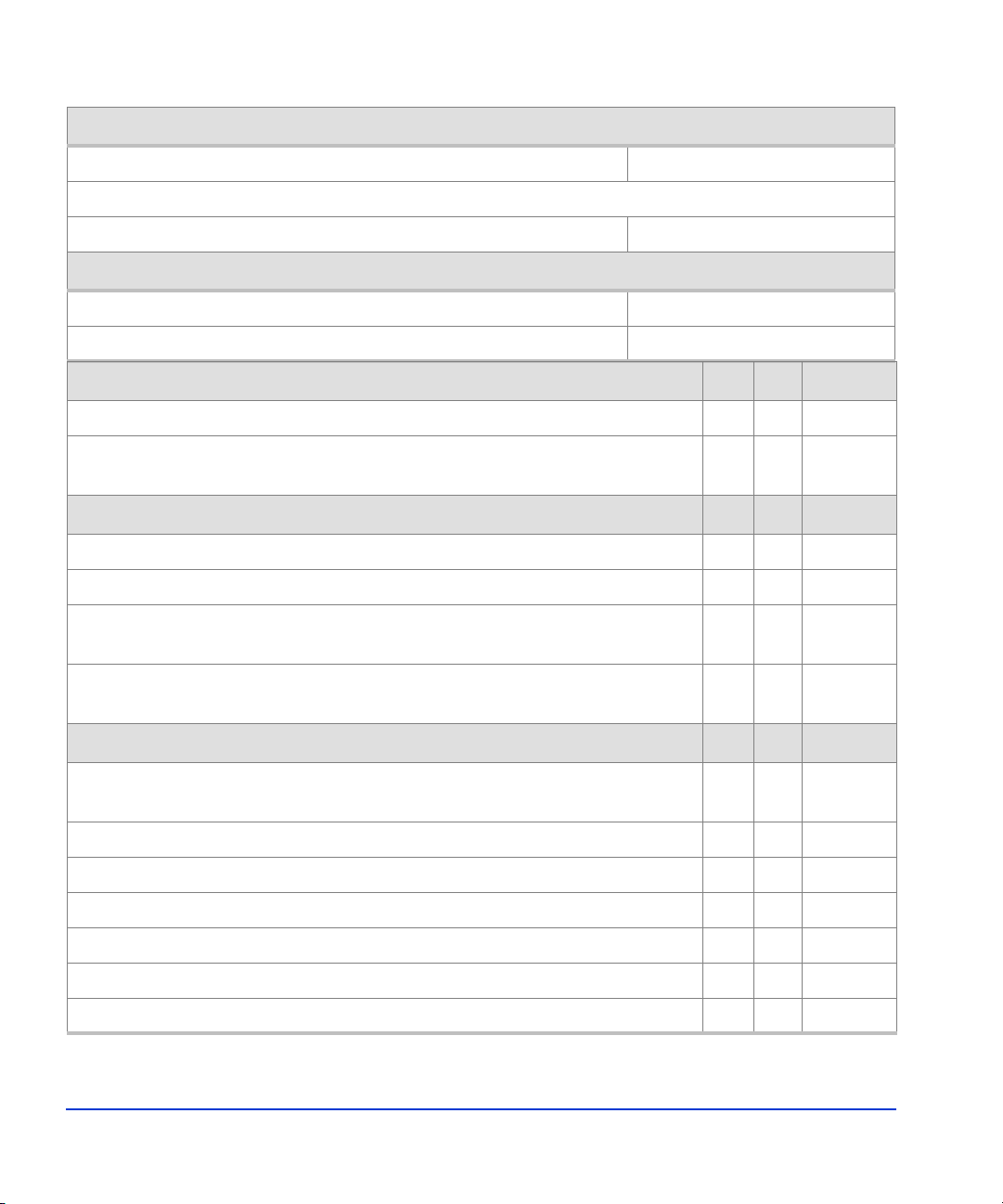
Customer summary
Customer: Date:
Address:
Contact: Phone:
HP summary
HP SR: Phone:
HP representative: Phone:
Safety Yes No Reference
Is there a fire protection system in the computer room? *❑❑page 27
Is the computer room free of any equipment servicing hazards (for example,
*❑❑page 27
electrical or data cables that obstruct access)?
Computer room space planning Yes No Reference
Is the existing floor plan documented? ❑❑page 32
Has a new floor plan been developed to include the new array? *❑❑page 32
Does the new floor plan include adequate space for airflow and servicing
*❑❑page 32
needs?
Does the new floor plan include the clearance required for the floor’s load
*❑❑page 33
rating?
Computer room infrastructure Yes No Reference
Is the computer room structurally complete (walls, floor, air conditioning
*❑❑Chapter 2
system, and so on)?
Is the raised floor adequate for the equipment load? *❑❑page 28
Is antistatic flooring or mats installed? *❑❑page 29
Are there cutouts or channels for cable routing? *❑❑page 29
Is there a dedicated analog telephone line for “phone home” configuration? *❑❑page 52
Is a telephone line available for HP representative use? *❑❑page 52
Is a private LAN available? *❑❑page 52
14 HP StorageWorks XP12000 Disk Array Site Preparation Guide

Computer room environment Yes No Reference
Can the temperature be maintained between 16° and 32° C? *❑❑page 47
Can temperature changes be held to less than 10° C per hour? *❑❑page 47
Can the humidity level be maintained between 20% and 80%? *❑❑page 47
Is the computer room protected against dust, pollution, and metallic
*❑❑page 50
particulate contamination?
Does the computer room support other environmental considerations (such
as vibration and acoustics)?
Computer room electrical Yes No Reference
*❑❑page 48–
page 50
Are two AC outlets, on different lines, available for the equipment? *❑❑page 53
Does the input voltage correspond to the DKC and DKU equipment
*❑❑page 53
specifications?
Are the input circuit breakers adequate for equipment loads? *❑❑page 53
Does the input frequency correspond to equipment specifications? *❑❑page 54
Is an appropriate uninterruptible power supply (UPS) strategy in place? *❑❑page 58
If lightning arresters are recommended, are they installed? *❑❑page 59
Have all sources of electrical interferences been corrected? *❑❑page 59
Building access and security Yes No Reference
Does the customer site have access control (for example, HP representatives
❑❑NA
will need an escort)?
Does the computer room have access control (for example, HP
❑❑NA
representatives will need a security code)?
Are all floors, stairs, elevators, stairwalkers, lifts, ramps, or ladders needed
*❑❑page 60
to move the equipment adequate to support its weight and size?
Will the equipment fit through all doors and corridors and in lifts? *❑❑page 60
Does the building have a loading dock? Maximum access height is _____m. ❑❑NA
Additional equipment Yes No Reference
For any additional equipment required (for example, connectors,
*❑❑NA
receptacles, cables, and any equipment not supplied by HP), is the
equipment on site and ready for use?
Site Prep Team and Tasks 15

Site prep time allowances
The following site prep tasks may require several weeks:
• Acquiring required power connectors
• Arranging for an electrician
• Adding or modifying air conditioning systems
• Making building alterations
• Placing an order for data comm equipment
The time between placing an equipment order and actual delivery can vary.
Contact your HP representative to determine the best estimated delivery
dates.
16 HP StorageWorks XP12000 Disk Array Site Preparation Guide

2
Site Requirements
Your site must meet the following requirements before HP can deliver and
install the disk array:
• General computer room requirements, page 25
• Safety requirements, page 27
• Raised floor requirements, page 28
• Space planning requirements, page 32
• Environmental requirements, page 46
• Data comm requirements, page 52
• Electrical requirements, page 53
• Delivery space requirements, page 60
Site Requirements 17
Disk array physical specifications
Mini
Use the information in this section to determine the total dimensions and
weight for your specific array configuration. You will need these values to
complete other procedures in this chapter.
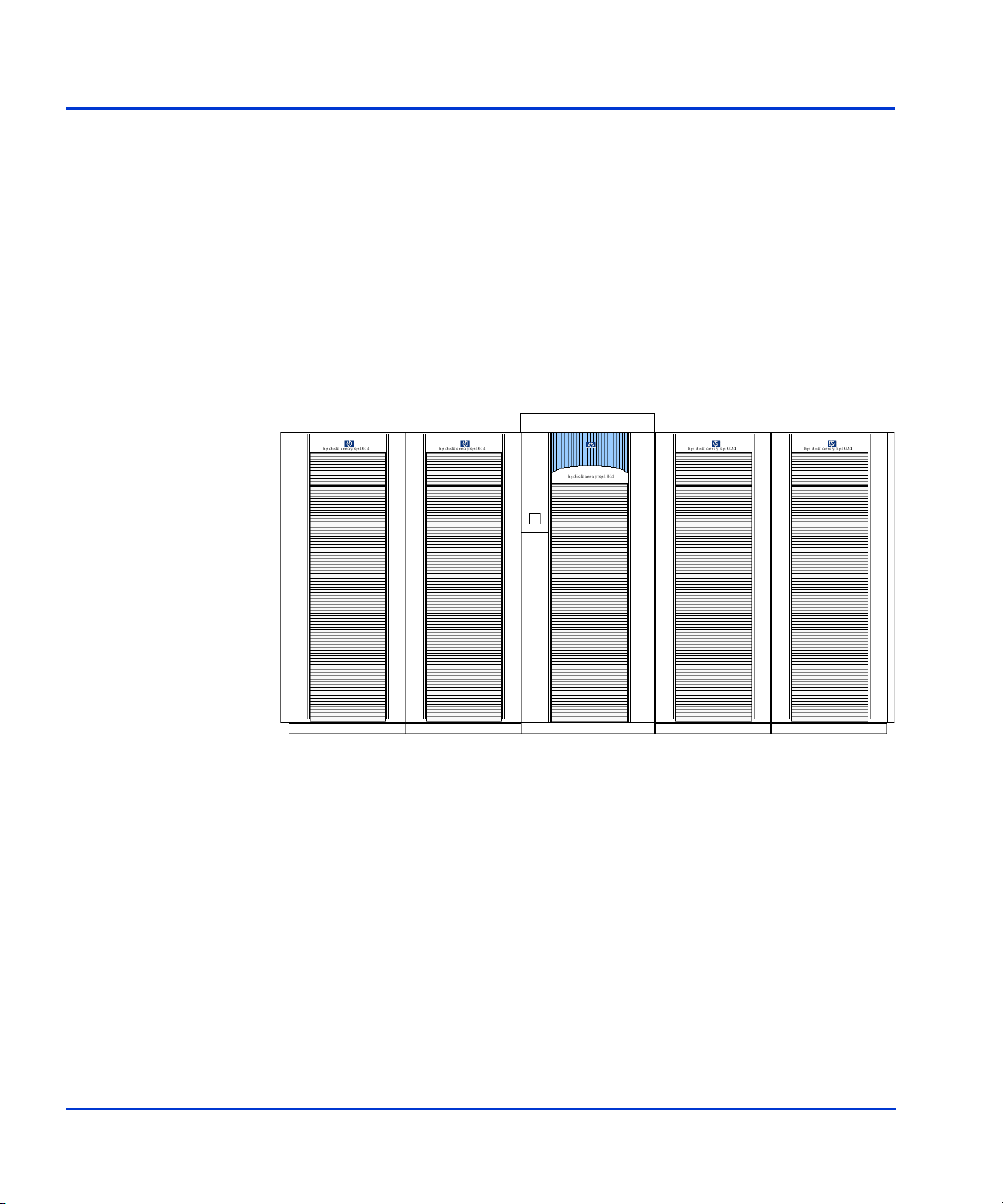
The disk array includes one disk controller frame (DKC), and zero to four
disk array frames (DKUs). The DKC contains the controller electronics for
the disk array and some hard disk drives. The DKUs contain additional
hard disk drives. Figure 1 shows a disk array with four DKUs.
mum disk subsystem
4th DKU (L2) 3rd DKU (L1) DKC 1st DKU (R1) 2nd DKU (R2)
Figure 1. Disk array minimum/maximum configuration
Supported configurations are:
• One DKC (minimum configuration)
• One DKC and one DKU (R1)
• One DKC and two DKUs (R1 and R2 or R1 and L1)
• One DKC and three DKUs (R1, R2, and L1 or R1, L1, and L2)
• One DKC and four DKUs (maximum configuration)
18 HP StorageWorks XP12000 Disk Array Site Preparation Guide

Dimensions
Use the packaged values when determining delivery space requirements
(page 60), and unpackaged values during space planning (page 32).
Table 2. DKC and DKU dimensions
DKC Unpackaged DKC Packaged DKU Unpackaged DKU Packaged
Dimension
Width 78.2
cm in cm in cm in cm in
1
30.8 89 35.04 65 25.6 79 31.2
Depth 92.5 36.42 112.5 44.3 92.5 36.42 112.5 44.3
Height 186 73.23 202 79.52 186 73.23 202 79.52
1 Includes two side panels of 1.6 cm (0.63 in.) width each.
Weights
Use the approximate packaged weights when determining delivery space
requirements (page 60), and unpackaged weights to calculate the total
weight of your configuration (page 22).
Table 3 (page 20) provides the approximate weights for:
• Minimum configuration — base cabinet without additional product
components
• Maximum configuration — base cabinet fully populated with product
components
Site Requirements 19
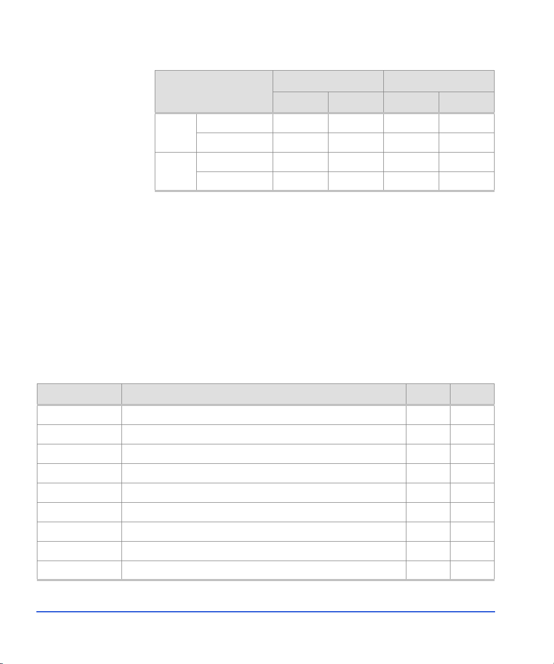
Table 3. DKC and DKU weights
Minimum configuration Maximum configuration
Cabinet
kg lb kg lb
Unpackaged 590 1300 875 1930
DKC
Packaged
1, 2
689 1518 989 2180
Unpackaged 429 945 739 1630
DKU
Packaged
1 For shipments from the USA to locations outside the USA and Canada, add 59 kg (130 lb)
for an international shipping crate.
2 Within the USA and Canada, most shipments use a special carrier process in which frames
are shipped without pallets, ramps, and cartons. In these cases, the packaged weight is the
unpackaged weight plus 23 kg (50 lb).
3 For upgrade DKU packaging (includes a ramp), add 29 kg (65 lb).
1, 3
499 1100 853 1880
The main factor that increases total weight is the number of disk drives.
The actual weight is the base cabinet weight plus the weight of all
additional components installed.
Table 4 provides the approximate weights of additional disk array
components when integrated into a DKC or DKU cabinet.
Table 4. Component weights
Product Description kg lb
AE002A #001 Three-phase 30A/60Hz for XP12000 DKC 22.6 50
AE002A #002 Three-phase 30A/50Hz for XP12000 DKC 20 44
AE002A #003 Single-phase 50A/60Hz for XP12000 DKC 21.3 47
AE002A #004 Single-phase 50A/50Hz for XP12000 DKC 17.2 38
AE002A #005 Single-phase 30A/60Hz for standard XP12000 DKC 20 44
AE002A #006 Single-phase 30A/50Hz for standard XP12000 DKC 18.6 41
AE002A #007 Single-phase 30A/60Hz for minimum XP12000 DKC 15.9 35
AE002A #008 Single-phase 30A/50Hz for minimum XP12000 DKC 15 33
AE003A XP12000 SVP High Reliability Support Kit 8.6 19
20 HP StorageWorks XP12000 Disk Array Site Preparation Guide

Table 4. Component weights (continued)
Product Description kg lb
AE004A XP12000 Power Control Interface Kit for Mainframe 0.5 1
AE006A XP12000 16-port 1–2 Gbps FC SW CHIP pair 5 11
AE007A XP12000 32-port 1–2 Gbps FC SW CHIP pair 5.9 13
AE008A XP12000 FC SFP Transceiver LW 0.03 0.05
AE013A XP12000 8-port 1–2 Gbps FICON SW CHIP pair 5.9 13
AE014A XP12000 8-port 1–2 Gbps FICON LW CHIP pair 5.9 13
AE017A XP12000 16-port EXSA CHIP pair 5.4 12
AE018A HP XP12000 8-Port 1 Gbps NAS SW CHIP 6.5 14
AE024A XP12000 DKC Power Supply 23.1 51
AE025A XP12000 4 GB Cache Memory Module 0.2 0.5
AE027A XP12000 Cache Platform Board 6.4 14
AE028A XP12000 DKC-DKU Battery 13.7 30
AE030A XP12000 1 GB Shared Memory Module 0.05 0.1
AE032A XP12000 Shared Memory Platform Board 2.3 5
AE033A XP12000 Cache Switch 3.6 8
AE034A XP12000 Standard Performance ACP pair 5 11
AE040A XP12000 Cable Set for DKU R1, basic 3.2 7
AE041A XP12000 Cable Set for DKU R1, high performance 4.1 9
AE042A XP12000 Cable Set for DKU L1, basic 4.1 9
AE043A XP12000 Cable Set for DKU L1, high performance 4.5 10
AE044A XP12000 Cable Set for DKU R2 or L2 2.3 5
AE045A #001 Three-phase 30A/60Hz for XP12000 DKU 22.6 50
AE045A #002 Three-phase 30A/50Hz for XP12000 DKU 20 44
AE045A #003 Single-phase 50A/60Hz for XP12000 DKU 21.3 47
AE045A #004 Single-phase 50A/50Hz for XP12000 DKU 17.2 38
Site Requirements 21

Table 4. Component weights (continued)
Product Description kg lb
AE045A #005 Single-phase 30A/60Hz for XP12000 DKU 20 44
AE045A #006 Single-phase 30A/50Hz for XP12000 DKU 18.6 41
AE046A XP12000 High Performance FC-AL Disk Path 6.8 15
AE050A XP12000 73 GB 15K rpm Array Group, four disks 4.5 10
AE050AS XP12000 73 GB 15K rpm Spare Disk 1.4 3
AE051A XP12000 146 GB 10K rpm Array Group, four disks 4.1 9
AE051AS XP12000 146 GB 10K rpm Spare Disk 0.9 2
AE053A XP12000 300 GB 10K rpm Array Group 4 9
AE053AS XP12000 300 GB 10K rpm Spare Disk 1 2
Calculating the weight of your disk array configuration
The total weight of your array configuration includes not just the DKC and
DKU(s), but also the number of disk drives in each cabinet and any
optional components. Your site must have adequate floor strength to
support the total weight of the array, from the delivery area to the computer
room.
Use the weight calculation worksheet (page 23) to calculate the total weight
of your unpackaged array configuration, in your preferred units (kg or lb).
See Table 6 (page 24) for an example of a completed worksheet.
Use the calculated total weight to estimate the required floor load rating for
the computer room (page 28).
22 HP StorageWorks XP12000 Disk Array Site Preparation Guide

Table 5. Weight calculation worksheet
Units (kg or lb)
Part Number Description Weight1Quantity
x=
x=
x=
x=
x=
x=
x=
x=
x=
x=
Extended
weight
x=
x=
x=
x=
x=
x=
x=
Total weight of your configuration
1From Table3 (page 20) or Table 4 (page 20).
Site Requirements 23

Weight calculation example
Table 6. Weight calculation worksheet example
Units (kg or lb)
Part Number Description Weight
Pounds (lb)
1
Quantity
Extended
weight
AE002A XP12000 Disk Control Frame (DKC) 1300 x 1 = 1300
AE002A #001 Three-phase 30A/60Hz for XP12000 DKC 50 x 1 = 50
AE007A XP12000 32-port 1–2 Gbps FC SW CHIP pair 13 x 2 = 26
AE013A XP12000 8-port 1–2 Gbps FICON SW CHIP pair 13 x 1 = 13
AE024A XP12000 DKC Power Supply 51 x 1 = 51
AE025A XP12000 4 GB Cache Memory Module 0.5 x 8 = 4
AE028A XP12000 DKC-DKU Battery 30 x 4 = 120
AE030A XP12000 1 GB Shared Memory Module 0.1 x 3 = 0.3
AE033A XP12000 Cache Switch 8 x 1 = 8
AE034A XP12000 Standard Performance ACP pair 11 x 2 = 22
AE040A XP12000 Cable Set for DKU R1, basic 7 x 1 = 7
AE041A XP12000 Cable Set for DKU R1, high performance 9 x 1 = 9
AE045A XP12000 Disk Array Frame (DKU) 945 x 1 = 945
AE045A #001 Three-phase 30A/60Hz for XP12000 DKU 50 x 1 = 50
AE046A XP12000 High Performance FC-AL Disk Path 15 x 1 = 15
AE051A XP12000 146 GB 10K rpm Array Group, four disks 9 x 70 = 630
AE051AS XP12000 146 GB 10K rpm Spare Disk 2 x 4 = 8
Total unpackaged weight of your configuration
1From Table3 (page 20) or Table 4 (page 20).
24 HP StorageWorks XP12000 Disk Array Site Preparation Guide
3258.3

General computer room requirements
The goal of a computer room is to maintain an ideal environment for
computer equipment, including XP disk arrays.
Make sure your computer room adheres to all national and local building
codes for a data center/computer room environment.
HP recommends that you follow these general guidelines:
• Locate the computer room away from exterior walls of the building to
avoid the heat gain from windows and exterior wall surfaces.
• When exterior windows are unavoidable, use windows that are double
or tripled glazed and shaded to prevent direct sunlight from entering
the computer room.
• Maintain the computer room at a positive pressure relative to the
surrounding spaces to reduce introduction of contaminants.
• Install a vapor barrier around the entire computer room envelope
(floors/walls/ceiling) to help keep moisture out of the room. This is
especially important if your computer room is located underground.
• Caulk and vapor-seal all pipes and cables that penetrate the computer
room envelope.
Preventing electrostatic discharge
Electrostatic discharge (ESD) can cause component damage during
servicing operations.
Static charges occur when objects are separated or rubbed together. The
voltage level of a static charge is determined by the following factors:
• Types of materials
• Relative humidity — low humidity contributes to undesirably high
levels of electrostatic charges, which increases the ESD voltage
potential.
Site Requirements 25

• Rate of change — a standard air conditioner both cools and removes
moisture from the air. The rate of change is how quickly the air in the
room is dried. The drier the air, the more static is generated. If you do
not use proper cooling equipment, air dryness can present problems.
• Separation — refers to the static discharge that can be generated when
two objects are separated. For example, printer paper is often stored in
cool dry conditions. If opened and used immediately, the act of
removing the paper from its box generates static. To allow the static to
discharge gradually over time, leave the box open in the computer
room for several hours before use.
Follow these precautions to minimize possible ESD-induced failures in
your computer room:
• Install conductive flooring (conductive adhesive must be used when
laying tiles).
• Use conductive wax if waxed floors are installed.
• Ensure that all equipment and flooring are properly grounded and are
at the same ground potential.
• Use conductive tables and chairs.
• Store spare electric parts in antistatic containers.
• Maintain recommended humidity level and airflow rates.
26 HP StorageWorks XP12000 Disk Array Site Preparation Guide

Safety requirements
When making decisions concerning site safety, your first concern should be
the safety of your personnel and then the safety of your equipment.
Fundamental safeguards for disk arrays should include a site well away
from any sources of potential damage.
If you have any questions on site safety, consult your HP representative,
your insurance carrier, and local building inspectors for safety
recommendations.
Fire safety
Do not install or operate the disk array in an environment where there is a
risk of fire or explosion due to the presence of highly flammable gases,
volatile liquids, or combustible dust.
Consult your insurance carrier and local fire department for fire safety
suggestions. They can analyze your existing fire control systems and advise
you on any required changes. If you are building a new site or making
structural changes to an existing site, consult your local building codes for
fire prevention and protection guidelines.
Equipment servicing hazards
Your staff and HP service personnel require safe access to the disk array.
Running electrical and data communication cables underneath your
computer room’s raised floor is the best way to ensure that they do not
create a safety hazard.
Site Requirements 27
Raised floor requirements
The computer room floor must be able to support the total weight of the
equipment as well as localized weight at each caster or foot of the
equipment cabinets. A common method of preparing an adequate floor for
a computer room is to construct a raised floor over the building floor. A
raised floor:
• Allows weight to be spread evenly across the floor
• Provides an under-floor area for running interconnecting cables
conveniently and unobtrusively
• Allows optimum distribution of conditioned air
Warning
If metal is used in the construction of the raised floor, ensure that there is a
common ground connection between the raised floor and main floor to
avoid possible build up of different voltage potentials. Failure to comply
can result in serious injury to personnel and damage to equipment.
Requirements for raised floors:
• Raised floor access ramps must not exceed a 10
• Use a 10- to 12-inch raised floor system for the most favorable room
air distribution system.
• Grid panels must be at least 45 x 45 cm (17.72 x 17.72 in).
• The floor must have a load rating between 300 and 500 kg per square
meter (553 to 921.7 lb per square yard, or 61.4 to 102.4 lb per square
foot). The maximum point floor loading is 500 kg (1102.3 lb).
To estimate the load rating you need for your floor, consider the total
weight of all of these items:
• The disk array; see “Weights” (page 19)
• Other equipment
28 HP StorageWorks XP12000 Disk Array Site Preparation Guide
° slope.

Floor covering
Caution HP strongly discourages the use of carpeting, including antistatic varieties,
Caution If your computer room has carpeting, place static discharge mats where
• Furniture such as desks, chairs, and storage cabinets
• Computer room personnel
• Moving equipment such as forklifts, dollies, and similar items
The lower the floor load rating, the more clearance is required around the
array to distribute the equipment weight correctly. If your computer room is
too small to allow for minimum required clearance around the array, you
may need to increase the floor load rating. For more on required clearance,
see “Floor clearance” (page 33).
HP recommends the use of a tiled raised floor.
within 6.0 m (20 ft.) of the disk array. Over time, carpeting may shed dust
that can cause problems with the disk array.
personnel must walk across them before touching any part of the array.
Failure to comply with this precaution can result in equipment damage
through static discharge.
Floor cutouts
Figure 2 (page 30) and Figure 3 (page 31) show the locations of floor
cutouts under the DKC and DKU. Basically, position floor cutouts toward
the center of the cabinet. The position may be off-center as long as the
cutout is within the allowable range and allows smooth entrance of an
external cable (check the relationship between the position of the cutout
and the opening on the bottom of the cabinet).
Site Requirements 29
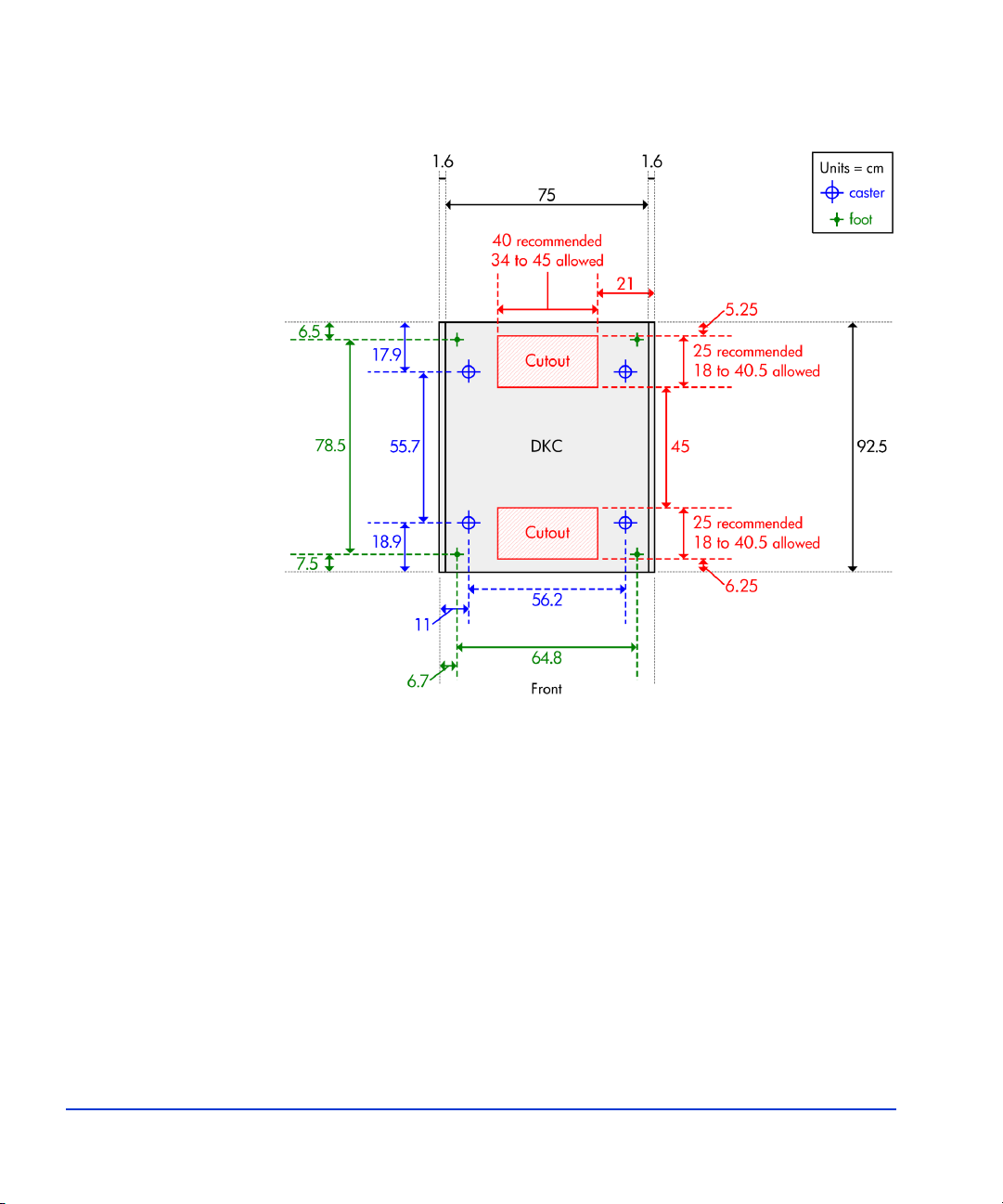
DKC floor cutouts
Figure 2. DKC floor cutouts
30 HP StorageWorks XP12000 Disk Array Site Preparation Guide

DKU floor cutout
Figure 3. DKU floor cutout
Site Requirements 31

Space planning requirements
Space planning involves making sure that your computer room:
• Is large enough to hold the new array and other equipment and
furniture
• Provides minimum clearance around the array for service access and
to ensure proper weight distribution on the computer room’s floor
• Includes correctly positioned floor cutouts for the array’s power and
data cables
The space planning process
1. Document your computer room’s existing floorplan, including the
locations of:
• Immovable objects, such as structural support columns
• Walls
• All equipment, furniture, cabinets, racks, data comm equipment,
and systems
• Floor cutouts
• Electrical outlets
• Interconnecting cables and power cords, including lengths
• Floor vents
2. Develop a new floorplan that includes the locations of:
• Immovable objects from your existing floorplan
• Walls
• The array with required clearance; see “Floor clearance” (page 33)
• All other equipment, furniture, cabinets, racks, data comm
equipment, and systems
• Floor cutouts; see “Floor cutouts” (page 29)
• Electrical outlets
32 HP StorageWorks XP12000 Disk Array Site Preparation Guide

Floor clearance
• Interconnecting cables and power cords (keep cables away from
traffic areas to help prevent accidents and equipment failures)
• Floor vents
• Enough space and lighting for people to work effectively on a daily
basis and for periodic equipment servicing
• Flexibility to accommodate additional equipment as your
requirements increase
3. Implement the new floor plan, leaving empty space where the array will
be installed. If the new floorplan requires construction changes, consult
with local contractors and your HP representatives.
The total floor clearance required for the disk array includes:
• The actual space required by the equipment.
• Service clearance — the floor space required to access the disk array.
Never use this space for storage.
• Additional space required to properly distribute the equipment weight
on your computer room’s raised floor. The amount of additional space
required depends on your floor load rating.
To determine the floor clearance required for your disk array configuration:
1. Refer to the appropriate diagram for your array configuration:
• DKC only—Figure 4 (page 36)
• DKC with one DKU—Figure 5 (page 38)
• DKC with two DKUs—Figure 6 (page 40)
• DKC with three DKUs—Figure 7 (page 42)
• DKC with four DKUs—Figure 8 (page 44)
Site Requirements 33

2. In the floor clearance diagram:
• Clearance “A” is the space between the service clearance at the left
side of the array (10 cm for the kickplate) and any other object,
such as a desk or wall.
• Clearance “B” is the space between the service clearance at the
right side of the array (10 cm for the kickplate) and any other
object.
• Clearance “C” is the space between the service clearance at the
front of the array and any other object.
You use the value of C and your floor load rating to determine the
values for A and B.
3. Determine how much space you can assign to clearance C. For
maintenance purposes, try to make C larger (100 cm) rather than smaller
(0 cm). The smaller C is, the larger A and B must be.
4. In the table after the diagram, find the column for C. If your C value is
in between two table values, use the larger table value. Then, find the
row for your floor load rating. Where the column and row intersect is
the A+B value.
5. To determine clearance A and clearance B, divide the A+B value
between A and B. They do not need to be equal. For example, if the
A+B value from the table is 60 cm, then A can be 40 cm and B can be
20, or both A and B can be 30. However, if your configuration includes
only a DKC, or a DKC and one DKU, then A must be at least 28 cm
(11.1 in) to allow for opening the DKC front door.
34 HP StorageWorks XP12000 Disk Array Site Preparation Guide

6. Calculate the floor clearance for the array:
Table 7. Calculating floor clearance
Left Right Front Back
Clearance values
Minimum service clearance
Minimum floor clearance
A = _________+B = _________+C = _________+Not applicable
10 cm (3.94 in)=10 cm (3.94 in)=80 cm (31.5 in)=80 cm (31.5 in)
80 cm (31.5 in)
Site Requirements 35

Floor clearance — DKC only
Figure 4. Floor clearance — DKC only
For an explanation of this diagram, see step 2 (page 34).
36 HP StorageWorks XP12000 Disk Array Site Preparation Guide

Table 8. A+B based on C and floor load rating — DKC only
Floor load
rating
(kg/m2)
C=0,
A+B must =
C=20 cm (7.9 in),
A+B must =
C=40 cm (15.8 in),
A+B must =
C=60 cm (23.6 in),
A+B must =
C=100 cm (39.4 in),
A+B must =
500 40 30 20 0 0
450 50 40 30 20 0
400 80 60 50 40 20
350 110 90 80 60 40
300 170 140 120 100 80
Site Requirements 37

Floor clearance — DKC and one DKU
Figure 5. Floor clearance — DKC and one DKU
For an explanation of this diagram, see step 2 (page 34).
38 HP StorageWorks XP12000 Disk Array Site Preparation Guide

Table 9. A+B based on C and floor load rating — DKC and one DKU
Floor load
rating
(kg/m2)
C=0,
A+B must =
C=20 cm (7.9 in),
A+B must =
C=40 cm (15.8 in),
A+B must =
C=60 cm (23.6 in),
A+B must =
C=100 cm (39.4 in),
A+B must =
500 80 60 40 20 0
450 110 90 70 50 20
400 160 130 100 80 50
350 230 190 160 130 90
300 330 280 240 210 160
Site Requirements 39

Floor clearance — DKC and two DKUs
Figure 6. Floor clearance — DKC and two DKUs
For an explanation of this diagram, see step 2 (page 34).
40 HP StorageWorks XP12000 Disk Array Site Preparation Guide

Table 10. A+B based on C and floor load rating — DKC and two DKU
Floor load
rating
(kg/m2)
C=0,
A+B must =
C=20 cm (7.9 in),
A+B must =
C=40 cm (15.8 in),
A+B must =
C=60 cm (23.6 in),
A+B must =
C=100 cm (39.4 in),
A+B must =
500 120 90 60 40 0
450 170 130 100 70 30
400 240 200 160 130 80
350 340 280 240 200 140
300 500 430 370 320 240
Site Requirements 41

Floor clearance — DKC and three DKUs
Figure 7. Floor clearance — DKC and three DKUs
For an explanation of this diagram, see step 2 (page 34).
42 HP StorageWorks XP12000 Disk Array Site Preparation Guide

Table 11. A+B based on C and floor load rating — DKC and three DKUs
Floor load
rating
(kg/m2)
C=0,
A+B must =
C=20 cm (7.9 in),
A+B must =
C=40 cm (15.8 in),
A+B must =
C=60 cm (23.6 in),
A+B must =
C=100 cm (39.4 in),
A+B must =
500 160 120 80 50 0
450 230 180 140 100 50
400 320 260 210 170 100
350 460 380 320 270 190
300 660 570 490 420 320
Site Requirements 43

Floor clearance — DKC and four DKUs
Figure 8. Floor clearance — DKC and four DKUs
For an explanation of this diagram, see step 2 (page 34).
44 HP StorageWorks XP12000 Disk Array Site Preparation Guide

Table 12. A+B based on C and floor load rating — DKC and four DKUs
Floor load
rating
(kg/m2)
C=0,
A+B must =
C=20 cm (7.9 in),
A+B must =
C=40 cm (15.8 in),
A+B must =
C=60 cm (23.6 in),
A+B must =
C=100 cm (39.4 in),
A+B must =
500 200 150 100 70 0
450 290 230 170 130 60
400 410 330 270 210 130
350 570 480 400 340 240
300 830 710 610 530 400
Site Requirements 45

Environmental requirements
The environmental specifications for operating your disk array must be
satisfied before installation.
Altitude
The maximum altitude for disk array operation is 3,000 meters. For
nonoperational or storage situations, the maximum altitude is 4,000 meters.
Air conditioning
Use separate computer room air conditioning duct work. If it is not separate
from the rest of the building, it might be difficult to control cooling and air
pressure levels. Duct work seals are important for maintaining a balanced
air conditioning system and high static air pressure. Adequate cooling
capacity means little if humidity levels increase when the ducts are exposed
to warm air, producing condensation. Condensation on any disk hardware
can damage the components.
Any questions regarding the adequacy of airflow construction should be
referred to and evaluated by a qualified structural engineer.
46 HP StorageWorks XP12000 Disk Array Site Preparation Guide

Temperature
Table 13. Temperature specifications
Temperature range type Range
Recommended operating temperature range 21° to 24°C
70° to 75°F
Operating temperature 16° to 32°C
61° to 89°F
Nonoperating temperature range –10° to +43°C
14° to 109°F
Humidity
Shipping and storage temperature
(product packed in factory packing)
Temperature shock immunity
(maximum rate of temperature change)
Over-temperature warning At 40°C
Over-temperature shutdown At 60°C
Maintain proper humidity levels. High humidity levels cause galvanic
actions to occur between some dissimilar metals. This eventually causes a
high resistance between connections, leading to equipment failure.
Low humidity contributes to undesirably high levels of electrostatic
charges. This increases the electrostatic discharge (ESD) voltage potential.
ESD can cause component damage during servicing operations.
Low humidity levels are often the result of the facility heating system and
occur during the cold season. Most heating systems provide air with a low
humidity level, unless the system has a built-in humidifier.
–25° to +60°C
–13° to +140°F
10°C per hour
18°F per hour
At 104°F
At 140°F
Site Requirements 47

You should not see any condensation in or around the disk array under any
conditions. There is no procedure for recovery from moisture condensation.
Table 14. Humidity specifications
Noncondensing relative
Humidity range type
humidity (RH)
Recommended operating humidity range at 22° C (71° F) 50% to 55%
Operating humidity range at 22° C (71° F) 20% to 80%
Nonoperating humidity range 8% to 90%
Shipping and storage humidity range (product packed in factory packing) 5% to 95%
Operating maximum wet bulb temperature 26° C (79° F)
Nonoperating maximum wet bulb temperature 27° C (81° F)
Shipping and storage maximum wet bulb temperature 29° C (84° F)
Mechanical vibration
Continuous vibration can cause a slow degradation of mechanical parts
and, when severe, can cause data errors in disk drives. Mechanical
connections such as printed circuit assembly (PCA) conductors, cable
connectors, and processor backplane wiring can also be affected by
vibrations. Vibration specifications apply to all three axes.
Table 15. Mechanical vibration specifications
Condition Specification
Operating 0.25 mm, 5–10 Hz
0.05 G, 10–300 Hz
Nonoperating 2.5 mm, 5–10 Hz
0.5 G, 10–70 Hz
0.05 mm, 70–99 Hz
1.0 G, 99–300 Hz
1
Shipping and storage (product packed in factory packing) 0.5 G, 15 min.
at four most severe
resonances between 5–200 Hz
1 See ASTM D999-91 Standard Methods for Vibration Testing of Shipping Containers.
48 HP StorageWorks XP12000 Disk Array Site Preparation Guide

Shock
Table 16. Shock specifications
Condition Specification
Operating None
Nonoperating 8 G, 15 ms
Shipping and storage (product packed in
factory packing)
Horizontal:
Incline impact: 1.22 m/s
1
1 See ASTM D5277-92 Standard Test Methods for Performing Programmed Horizontal
Impacts Using an Inclined Impact Tester.
2 See ASTM D1083-91 Standard Test Methods for Mechanical Handling of Unitized Loads
and Large Shipping Cases and Crates.
Heat dissipation and power consumption
Table 17 describes the heat dissipation and power consumption of the
XP12000 when fully loaded with the maximum number of disk drives.
Table 17. Heat dissipation and power consumption specifications
Parameter DKC Each DKU
Power consumption (kVA) 8.45 7.50 38.45
Heat dissipation (kW) 8.02 6.75 35.02
BTUs per hour 27370 23036 119514
kcal per hour 6897 5805 30117
Vertical:
2
Rotational edge: 0.1 m
Full array
(1 DKC and 4 DKUs)
Site Requirements 49

Acoustics
The acoustic emission specifications for the disk array are:
• 8.27 Bels (A) sound power
• 65 dB (A) sound pressure, operator position (1 meter from the floor
and surface of the cabinet)
You can reduce the ambient noise level caused by equipment and air
conditioning blowers in your computer room by:
• Installing a dropped ceiling covered in commercial-grade, fireresistant, acoustic-rated, fiberglass ceiling tile
• Covering the walls in sound-deadening material
• Installing foam rubber removable partitions
Dust and pollution control
Airborne contaminants and particles of a certain size and hardness can
damage the disk array. Some of the most common contaminants are dust,
smoke, ash, eraser debris, food crumbs, and salty air.
Mechanical filters on the disk array protect it by trapping large dust
particles. Smaller particles can pass through some filters, and can
eventually cause problems in mechanical parts. Prevent small dust particles
from entering the computer room by maintaining its air conditioning
system at a high static air pressure level.
Your HP representative can help you determine if you need to be concerned
about airborne contaminants.
Metallic particulate contamination
Metallic particulates can be especially harmful around electronic
equipment. This type of contamination may enter the data center
environment from a variety of sources, including but not limited to raised
floor tiles, worn air conditioning parts, heating ducts, rotor brushes in
50 HP StorageWorks XP12000 Disk Array Site Preparation Guide

vacuum cleaners, or printer component wear. Because metallic particulates
conduct electricity, they have an increased potential for creating short
circuits in electronic equipment.
Over time, very fine whiskers of pure metal can form on electroplated zinc,
cadmium, or tin surfaces. If these whiskers are disturbed, they may break
off and become airborne, possibly causing failures or operational
interruptions. For over 50 years, the electronics industry has been aware of
the relatively rare but possible threat posed by metallic particulate
contamination. During recent years, a growing concern has developed in
computer rooms where these conductive contaminants are formed on the
bottom of some raised floor tiles.
Although this problem is relatively rare, it may be an issue within your
computer room. Since metallic contamination can cause permanent or
intermittent failures on your electronic equipment, HP strongly
recommends that your site be evaluated for metallic particulate
contamination before installation of electronic equipment.
Site Requirements 51

Data comm requirements
Route data comm cables away from areas of high static electric fields
created by power transformers and heavy foot traffic. Use shielded data
comm cables that meet approved industrial standards to reduce the effects
of external fields.
For the XP disk array, you need:
Table 18. Computer room data comm requirements
Item Description
A dedicated analog
phone line
A twisted pair (Cat 5)
cable
An available LAN drop
on your Intranet
A public voice phone
line near the disk array
Needed for the HP StorageWorks Continuous
Track XP “phone home” feature, if you plan to
use it. An HP representative will configure
Continuous Track XP during installation. For
more information on Continuous Track XP, see
the HP StorageWorks XP12000 Disk Array
Owner’s Guide.
Needed to connect the XP12000 to an available
Ethernet port on your public LAN. To ensure
network security, consult with an HP
representative and your network administrator
before selecting the appropriate location of
your LAN drop.
Needed to allow your staff and HP
representatives to communicate inside and
outside your site.
52 HP StorageWorks XP12000 Disk Array Site Preparation Guide

Electrical requirements
Line voltage
Line voltage (AC) at the wall power outlet is a function of the local power
utility and your building power distribution network. Voltages outside of
the operating range of the disk array can cause intermittent system errors or
a complete system shutdown. If required, an HP representative and your
electrician can determine the current line voltage and make
recommendations. See Appendix A for specific AC line voltage
requirements.
Avoid the use of a line voltage conditioner.
Make sure that a power distribution unit (if used) provides the correct
voltage to support your entire system.
Branch circuit breakers
See Appendix A for specific branch circuit requirements for your power
situation.
Three-phase branch circuit breakers
The power cords supplied with each DKC or DKU configured for
three-phase power are sized for connection to a 30-amp circuit.
Single-phase branch circuit breakers
The power cords supplied with each DKC or DKU configured for
single-phase power are sized for connection to a 30- or 50-amp circuit.
Note 30-amp, single-phase power is available by special order only.
Site Requirements 53

Frequency
Usually, AC line frequency is determined by your local power providers. In
some cases, electrical power is supplied by motor-generators. Shifts in AC
line frequency can cause system errors. An HP representative can monitor
the frequency of the input AC line power and make recommendations, if
necessary. The disk array requires that the line frequency be within 0.5 Hz
of the rated line frequency (50 Hz or 60 Hz).
See Appendix A for more information.
Safety and dedicated ground
The primary reason for grounding electrical systems is safety. The safety
ground is required by the National Electric Code (USA) and most other
local, regional, and national codes. In addition to safety ground, HP
requires that a dedicated (earth reference) ground be installed as a common
reference point for all system components. Consult with an HP
representative and your electrician to ensure that your electrical system
meets all local and national safety codes.
Grounding requirements
Your site’s electrical subsystem must meet all of the following conditions:
• Grounding as prescribed by your local country codes.
• An insulated grounding conductor that is identical in size and
insulation material and thickness to the ungrounded branch-circuit
supply conductors. It should be green, with or without yellow stripes,
and is to be installed as a part of the branch circuit that supplies the
unit or system. This means the ground conductor must be run in the
same conduit, armored cable, or other cable bundle as the phase wires.
• The grounding conductor should be grounded to earth at the service
equipment or other acceptable building earth ground such as the
building frames (in case of a high-rise steel-frame structure).
• IT-configured grounding systems are not certified for use with the disk
array as these grounding systems may not have solidly
54 HP StorageWorks XP12000 Disk Array Site Preparation Guide

Receptacles
conductor-connected grounded power systems and/or they may have
resistive impedance inserted in ground and/or neutral lines. The disk
array requires a solidly conductor-connected ground and may require a
separate neutral in the case of WYE or STAR connections. For HP
disk arrays, TN grounding systems are preferred.
Each disk array cabinet has two or four separate connections to AC power.
• For disk array cabinets with two connections to AC power, each input
must be capable of supporting the entire current demand for the
cabinet.
• For disk array cabinets with four connections to AC power, the two
inputs to AC Box 1 or the two inputs to AC Box 2 must be capable of
supporting the entire current demand for the cabinet.
Figure 9 shows two examples of the fault-tolerant operation of the disk
array.
Figure 9. Examples of fault-tolerant power connections
Site Requirements 55

When receptacles are used to connect disk array components to AC power,
they must include a dedicated ground connection that is insulated from the
receptacle. It is important that the receptacle box be grounded with an
additional ground connection that is separate from the dedicated ground.
The additional ground can be hard conduit.
Specific power plugs and receptacles are required for the DKC and DKUs
depending on the power option you specify when ordering the HP XP12000
disk array. The power cords on 60 Hz cabinets are shipped with plugs
attached and connected. The power cords on 50 Hz cabinets are shipped
without plugs. You are responsible for having the correct plugs and
receptacles installed by an electrician in compliance with local electrical
requirements and practices.
Caution When installing the receptacles, the electrician must ensure that each
receptacle has its own neutral (if required) and ground. Using the same
neutral/ground for more than one circuit causes voltage loss and heat
problems and can create a fire hazard. A shared neutral conductor that
fails open-circuit can cause overvoltage damage to equipment.
See Appendix A for specific plug and receptacle part numbers and ordering
information.
Power line transients
Heavy electrical loads from nearby machinery or equipment (for example,
elevators or electric welders) can cause intermittent system problems with
sophisticated electronic equipment, even if that equipment is on a separate
circuit breaker. When faced with these conditions, provide a separate,
completely independent power panel with an isolated ground and circuit
breaker coming directly from the main building power source or secondary
power source.
If necessary, an HP representative can measure your power line noise level
and make appropriate recommendations concerning the use of line
treatment devices.
56 HP StorageWorks XP12000 Disk Array Site Preparation Guide

Maximum peak inrush and crest factor
Table 19. Maximum peak inrush
Cabinet Power Single-phase Three-phase
DKC 30-amp 46 A 34 A
50-amp 60 A Not applicable
DKU 30-amp 34 A 26 A
50-amp 56 A Not applicable
1 50-amp power configurations are single-phase only.
Table 20. Crest factors
Cabinet Power Single-phase Three-phase
DKC 30-amp 1.68 1.67
50-amp 1.56 Not applicable
DKU 30-amp 1.65 1.53
50-amp 1.50 Not applicable
1 50-amp power configurations are single-phase only.
1
1
1
1
Site Requirements 57

Uninterruptible power supply (UPS)
Most disk array units are installed in data centers where a UPS strategy is
already in place. However, if you are making your first large disk array
purchase, you may need a separate UPS solution.
Caution This section discusses a product UPS. If you are planning or already have
a site-wide UPS, HP recommends against using a product UPS powered by
a site-wide UPS for the XP12000.
Make sure your UPS satisfies the requirements in Table 21. Table values
are based on a worst-case voltage (rated voltage –10 percent) and a
maximum configuration of DKC/DKUs. A phase imbalance of 15 percent
is also included in the calculation.
Table 21. Single secondary input (primary offline) power requirements
Single-phase 30A Single-phase 50A Three-phase 30A
Input (Vac)
DKC
Each additional
DKU
DKC
Each additional
DKU
Each additional
DKU
208 20.0 A 17.3 A 40.0 A 34.6 A 20.0 A
400
Not applicable Not applicable
Not applicable Not applicable
10.4 A
In a maximum disk array configuration (one DKC and four DKUs), the
array requires 31 kVA.
58 HP StorageWorks XP12000 Disk Array Site Preparation Guide

Sources of electrical interference
Ensure that the disk array is protected from sources of electrical
interference:
Table 22. Sources of electrical interference
Potential source Description
Wall outlets Convenience power outlets for building maintenance
Lightning In geographical areas subject to lightning storms, it
equipment (such as vacuum cleaners and floor buffers)
must be wired from circuit breakers on a power panel
separate from the computer system panel. The ground
wires from these outlets must be connected to the
normal building distribution panel and not to the
system ground.
If a separate power source and separate ground are not
provided, operation of janitorial equipment can induce
electrical noise and cause abnormal operation of the
computer system. Your electrician can verify whether
or not maintenance outlets are on separate panels.
may by advisable to install lightning protection for
both personnel and computer systems. The principles
of lightning protection and personnel safety are
outlined in detail in the lightning protection code
contained in the National Fire Protection Association
(NFPA) Handbook.
Electromagnetic
interference
The disk array is specifically designed to reduce its
susceptibility to radiated and conducted interference.
Electromagnetic interference can cause a variety of
system problems. An HP representative can advise you
about the most common causes of electromagnetic
interference.
Site Requirements 59

Delivery space requirements
The delivery area must provide enough space and floor strength to support
the packaged equipment cartons for the disk array. Refer to the packaged
dimensions in “Dimensions” (page 19) and the packaged weights in
“Weights” (page 19).
Caution Make sure that your doorways and hallways provide enough clearance to
move the equipment safely from the delivery area to the computer room.
Permanent obstructions such as pillars or narrow doorways can cause
equipment damage. If necessary, plan for the removal of walls or doors.
Caution Make sure all floors, stairs, and elevators you use when moving the disk
array to the computer room can support the weight and size of the
equipment. Failure to do so could damage the equipment or your site.
60 HP StorageWorks XP12000 Disk Array Site Preparation Guide

3
Delivery and Unpacking
The disk array equipment is shipped directly from HP. If the disk array is
part of a system order, HP coordinates shipment from all HP locations so
that all of the equipment arrives at your site at approximately the same
time.
When your equipment ships, HP provides you with carrier information and
an expected delivery date. Factors beyond HP’s control can cause delivery
delays. If you have not received your equipment within two weeks of its
shipment from HP, contact your HP SR, who will trace your order and
expedite delivery.
Caution Before delivery, make sure your site meets “Delivery space requirements”
(page 60).
Delivery and Unpacking 61

Checking for shipping shortage and damage
Upon delivery of each equipment shipment:
1. Check the carrier’s bill of lading to ensure that the items listed match
the items delivered. Notify the carrier immediately if there are any
discrepancies or missing items.
2. Inspect all shipping containers for signs of damage, such as dents,
scratches, cuts, or water marks.
3. If you see any damage to the containers:
a. Note on the bill of lading that there is apparent damage, subject to
inspection.
b. Arrange for the carrier’s representative and an HP representative to
be present when the item in question is unpacked.
c. Contact your HP representative, who will make sure any damaged
components are replaced, regardless of the circumstances and
without waiting for any claim settlements.
62 HP StorageWorks XP12000 Disk Array Site Preparation Guide

Unpacking the equipment
HP representatives will supervise the unpacking and moving of the disk
array equipment. It is your responsibility to provide the people, tools, and
equipment necessary to perform these tasks.
Packaging configurations
XP disk array cabinets are shipped in one of three standard packaging
configurations:
• Environmental pack — consists of stretch wrap over corner protectors.
No special tools or procedures are required to unpack shipments in this
form. This packaging is used for most shipments within the USA and
Canada that are direct from the factory to the customer. HP uses
special carriers with a dedicated fleet of trucks and specially trained
personnel.
• Full packaging — consists of a pallet, wooden loading ramp, inner
packaging, and outer corrugated carton assembly.
• Full packaging with wooden crate — consists of full packaging
encased in a wooden crate.
Required personnel
HP recommends that three physically able personnel be available to assist
with off-loading the disk array equipment from the pallet. Personnel must
be knowledgeable and experienced with the safe handling of large, heavy,
and sensitive computer equipment.
Required tools
• Claw hammer (if full packaging with wooden crate)
• Ratchet wrench or box-open end wrench sizes 11mm (7/16") and
19mm (3/4"), or adjustable end wrench
• 6mm hex wrench
Delivery and Unpacking 63

Unpacking process
• Scissors or box knife to cut polyester banding
• Safety glasses
• Short stepladder (helpful, but not required)
If you need to unpack the equipment without HP supervision, follow the
instructions in this section.
1. Following the steps “Removing packaging materials” (page 66), unpack
the DKC and DKU equipment cartons outside of the computer room to
avoid debris and possible contamination of the computer room
environment.
2. For software CDs, cables, and other installation hardware, leave the
sealed cartons or packages intact. HP representatives will unpack them
when they install and configure the disk array.
3. As you unpack the cartons, match the delivered items to the packing list
(invoice) for each carton. Contact your HP SR immediately if any items
are missing or are not the ones you ordered.
4. Move all equipment to the computer room before the installation date.
Safety precautions
Caution Be very careful when handling the equipment. Do not drop the equipment
from a height of more than 0.5 cm (0.2 in). Floor unevenness must be less
than 1 cm (0.4 in).
Warning
The DKC and DKU are very heavy. To avoid injury, use appropriate
lifting tools and have three people unpack and move the equipment.
64 HP StorageWorks XP12000 Disk Array Site Preparation Guide

Caution Any movement of the equipment by forklift should be done prior to
unpacking. The carton assembly provides the most secure support of the
equipment during movement. Transporting the equipment by forklift after
the packaging carton has been removed is not advisable.
Caution DKCs and DKUs are top heavy and contain very sensitive electronic and
mechanical components.When moving on frame casters, the rolling surface
must be able to support the equipment weight and must be free of surface
conditions that could cause shock or vibration to the cabinet contents.
Warning
When using sharp objects or cutting tools, make sure that no part of your
body lies in the path of the blade bit or point.
Caution When detached from each other, DKCs and DKUs do not have side panels.
Exposed printed circuit boards (PCB) are present; however, normal
handling of the cabinet by the metal frames does not pose any ESD risks.
Caution When disk array equipment is not located in a data center or computer
room, it must be stored in a controlled area that meets environmental
requirements ((page 46).
Delivery and Unpacking 65

Removing packaging materials
Unpack the DKC first. DKC packaging contains a wooden ramp; standard
DKU packaging does not
1
. You will use the ramp to unload both the DKC
and DKUs.
1. If shipped in a wooden crate:
a. Using an 11mm (7/16") ratchet or wrench, remove the six lag screws
at the base of crate.
b. Using the claw end of a claw hammer, remove the crate clamps.
Warning
Crate clamps are under tension. Wear safety glasses and hold onto the
clamp with your free hand during removal.
c. Remove the crate panels.
1 DKUs shipped as upgrades (without a DKC) will contain a ramp.
66 HP StorageWorks XP12000 Disk Array Site Preparation Guide

P-fasteners
Polyester bands
Nails
Figure 10. Typical full frame outer packaging
2. Cut and remove the polyester bands.
3. Remove the nails attaching the carton to the pallet.
4. Remove the plastic carton fasteners (p-fasteners).
5. Remove the carton.
Delivery and Unpacking 67

Poly bag
Corner pads
Wooden ramp
Accessory box
Adapter plate
Figure 11. Typical full frame inner packaging with ramp
6. Remove the accessory boxes, ramp, and corner pads.
7. Using a 6mm hex and 19mm wrench, remove the adapter plates that
anchor the cabinet to the pallet.
8. Remove the poly bag covering the cabinet.
9. Following the instructions provided on the wooden ramp, attach the
ramp to the pallet and roll the cabinet onto the floor.
10. Visually check the unit for any damage.
68 HP StorageWorks XP12000 Disk Array Site Preparation Guide

A
Electrical Specifications
The detailed electrical specifications in this appendix are provided to help
your site electrician perform any necessary electrical work related to site
prep.
Electrical Specifications 69

AC line voltage requirements
50-amp, single-phase DKC
Table 23. 50-amp, 50 or 60 Hz, single-phase DKC operation
Nominal rated voltage (Vac)
Parameter 200 208
1
220 230 240
Minimum operating voltage (Vac) 184 191 202 212 221
Maximum operating voltage (Vac) 212 220 233 244 254
Rated line current per power cord (Arms) 22.6 21.7 20.5 19.6 18.8
Number of power cords 22222
Recommended circuit breakers 50A 50A 50A 50A 50A
Number of circuit breakers 22222
Dropout carry-through time at minimum line voltage (ms) 60 60 60 60 60
1 60 Hz only.
30-amp, single-phase DKC
Table 24. 30-amp, 50 or 60 Hz, single-phase DKC operation
Nominal rated voltage (Vac)
Parameter 200 208
Minimum operating voltage (Vac) 184 191 202 212 221
Maximum operating voltage (Vac) 212 220 233 244 254
1
220 230 240
Rated line current per power cord (Arms) 11.3 10.9 10.3 9.8 9.4
Number of power cords
2
44444
Recommended circuit breakers 30A 30A 30A 30A 30A
Number of circuit breakers 44444
Dropout carry-through time at minimum line voltage (ms) 60 60 60 60 60
1 60 Hz only.
2 Units with only two power cords require only two circuit breakers.
70 HP StorageWorks XP12000 Disk Array Site Preparation Guide

30-amp, three-phase DKC
Table 25. 30-amp, 50 or 60 Hz, three-phase DKC operation
Nominal rated voltage (Vac)
Parameter 200 208
1
220 230 240 380 400 415
Minimum operating voltage (Vac) 184 191 202 212 221 350 368 382
Maximum operating voltage (Vac) 212 220 233 244 254 403 424 440
Rated line current per power cord (Arms) 13 12.5 11.9 11.3 10.9 6.9 6.5 6.3
Number of power cords 2 2222222
Recommended circuit breakers 30A 30A 30A 30A 30A 30A 30A 30A
Number of circuit breakers 2 2222222
Dropout carry-through time at minimum
60 60 60 60 60 60 60 60
line voltage (ms)
1 60 Hz only.
50-amp, single-phase DKU
Table 26. 50-amp, 50 or 60 Hz, single-phase DKU operation
Nominal rated voltage (Vac)
Parameter 200 208
1
220 230 240
Minimum operating voltage (Vac) 184 191 202 212 221
Maximum operating voltage (Vac) 212 220 233 244 254
Rated line current per power cord (Arms) 18 17.3 16.4 15.7 15.0
Number of power cords 22222
Recommended circuit breakers 50A 50A 50A 50A 50A
Number of circuit breakers 22222
Dropout carry-through time at minimum line voltage (ms) 60 60 60 60 60
1 60 Hz only.
Electrical Specifications 71

30-amp, single-phase DKU
Table 27. 30-amp, 50 or 60 Hz, single-phase DKU operation
Nominal rated voltage (Vac)
Parameter 200 208
1
220 230 240
Minimum operating voltage (Vac) 184 191 202 212 221
Maximum operating voltage (Vac) 212 220 233 244 254
Rated line current per power cord (Arms) 9 8.7 8.2 7.8 7.5
Number of power cords 44444
Recommended circuit breakers 30A 30A 30A 30A 30A
Number of circuit breakers
2
44444
Dropout carry-through time at minimum line voltage (ms) 60 60 60 60 60
1 60 Hz only.
2 Units with only two power cords require only two circuit breakers.
30-amp, three-phase DKU
Table 28. 30-amp, 50 or 60 Hz, three-phase DKU operation
Nominal rated voltage (Vac)
Parameter 200 208
1
220 230 240 380 400 415
Minimum operating voltage (Vac) 184 191 202 212 221 350 368 382
Maximum operating voltage (Vac) 212 220 233 244 254 403 424 440
Rated line current per power cord (Arms) 10.4 10.0 9.4 9.0 8.7 5.5 5.2 5.0
Number of power cords 2 2222222
Recommended circuit breakers 30A 30A 30A 30A 30A 30A 30A 30A
Number of circuit breakers 2 2222222
Dropout carry-through time at minimum
60 60 60 60 60 60 60 60
line voltage (ms)
1 60 Hz only.
72 HP StorageWorks XP12000 Disk Array Site Preparation Guide

Receptacle part numbers and ordering information
Table 29 lists the plug and receptacle part numbers for 60 Hz
configurations of the XP12000 disk array.
Table 29. 60 Hz power plugs and receptacles
Power source Breaker rating Plug Receptacle
Single-phase 30 A Russellstoll 3750DP Russellstoll 3933 (alt. 9C33U0) or
3753 (alt. 9R33U0W)
50 A Russellstoll 9P53U2 Russellstoll 9C53U2 or 9R53U2W
Three-phase 30 A Russellstoll 3760PDG Russellstoll 3934 (alt. 9C34U0) or
3754 (alt. 9R34U0W)
Russellstoll connectors are available through most electrical distributors.
HP has arranged for the distributors listed below to stock these connectors.
These distributors are able to ship worldwide via your preferred carrier.
Beck Electrical Supply
2775 Goodrick Avenue
Richmond, CA 94801 USA
Telephone: (800) 466-4395
Fax: (800) 466-5442
Contact: Ken Mogan
casales@beckelectric.com
Source Research, Inc. (SRI)
2160 Sunnydale Boulevard
Clearwater, FL 33765-2108 USA
Telephone: (800) 356-0259
Contact: Erik Peterson, telephone extension 302
http://www.sourceresearch.com/index.cfm
Electrical Specifications 73

Three-phase cabling for the USA (60 Hz)
Each three-phase DKU has two main disconnect devices (two main
breakers for dual power lines) so that AC power to the unit can be supplied
from separate power distribution panels with two power-supply cords.
Caution An HP representative should be present whenever the disk array is being
connected to a new power source for the first time.
Connecting the external power-supply cords
The XP12000 disk array is factory-configured for 30-amp, three-phase
power.
When the disk array uses 30-amp, three-phase input power, the DKC and
DKUs have two power cords each.
Figure 12. 30-amp, three-phase power cords
If one power source malfunctions, the other power source assumes the total
load, providing uninterrupted operation. HP recommends that each power
74 HP StorageWorks XP12000 Disk Array Site Preparation Guide

cord have a separate electrical circuit as its source, in case of a circuit
failure. Each power-supply cord is supplied with an attachment plug type
Russellstoll 3760PDG.
Be sure to install Russellstoll 3934 (alternate, 9C34U0) or 3754 (alternate,
39R34U0W) socket receptacles between the power distribution panel of the
building and the power plugs for the unit.
The power cords provided with the disk array are nonshielded, type ST or
equivalent with four #8 AWG (minimum) conductors terminated at one end
with an assembled plug connector.
Branch circuit requirements
To protect the disk array, your building must be wired correctly. Each
supply (“hot”) conductor must be protected by a short-circuit protective
device and by an overcurrent protective device. Table 25 (page 71) and
Table 28 (page 72) provide specifications for the overcurrent protective
devices required for three-phase operation.
All protective devices must comply with national standards of the country
where the units are to be installed. If a protective device interrupts any
supply conductor, it must also interrupt all other supply conductors.
Overcurrent protection is not required for the neutral conductor of this unit.
Only 50 Hz, three-phase configurations have a neutral conductor.
Electrical Specifications 75

Three-phase AC cabling for Europe (50 Hz)
Each three-phase DKU has two main disconnect devices (two main
breakers for dual power lines) so that AC power to the unit can be supplied
from separate power distribution panels with two power-supply cords.
Caution An HP representative should be present whenever the disk array is being
connected to a new power source for the first time.
Connecting the power-supply cords
All 50 Hz, European XP12000 disk array cabinets are shipped with
unterminated power cords. Your electrician must select and install the
correct power plug. Be sure to prepare the socket receptacles and power
cords between the power distribution board of the building and the
attachment plugs for the unit. 30-amp power cords of type H07RN-F or
equivalent, with five 6 mm
unit.
Caution Be sure to connect the power cords to the distribution panel as shown in
Figure 13. Improper wiring of the neutral conductor may cause damage to
the disk array. To reduce the risk of a wrong connection, use a plug and
socket that are approved for this disk array. It is your electrician’s
responsibility to select and install the proper plug.
2
conductors per cord, are provided with the
Figure 13. Three-phase power connections for Europe
76 HP StorageWorks XP12000 Disk Array Site Preparation Guide

When connecting to 380 to 415 volt service, a WYE configuration with
neutral and ground conductors (in addition to the three-phase wires, for a
total of five wires) is required.
Warning
High leakage current can occur between the power supply and the unit. To
avoid electrical shock, be sure to make the protective earth connection
before the supply connections.
Branch circuit requirements
When the supplied line to line voltage is in the 380 to 415 volt range, the
connection must be a five-wire WYE or STAR connection.
To protect the disk array, your building must be wired correctly. Each
supply (“hot”) conductor must be protected by a short-circuit protective
device and by an overcurrent protective device. Table 25 (page 71) and
Table 28 (page 72) provide specifications for the overcurrent protective
devices required for three-phase operation.
All protective devices must comply with national standards of the country
where the units are to be installed. If a protective device interrupts a supply
conductor, it must also interrupt all other supply conductors.
Overcurrent protection is also required for the neutral conductor.
Electrical Specifications 77

Single-phase AC cabling for the USA
When configured for 50-amp, single-phase power, each XP12000 disk
array cabinet has two power cords and two main disconnect devices so that
AC power can be supplied from separate power distribution panels. When
configured for 30-amp, single-phase power, each XP12000 disk array
cabinet has four power cords and four main disconnect devices.
Caution An HP representative should be present whenever the disk array is being
connected to a new power source for the first time.
Connecting the power-supply cords
The XP12000 can be factory-configured for 50-amp or 30-amp,
single-phase power.
50-amp, single-phase power
Each 50-amp XP12000 disk array cabinet has two power-supply cords with
attachment plug type Russellstoll 9P53U2.
Figure 14. 50-amp, single-phase power cords
78 HP StorageWorks XP12000 Disk Array Site Preparation Guide

Be sure to install Russellstoll 9C53U2 or 9R53U2W socket receptacles
between the power distribution panel of the building and the power plugs
for the unit.
The power cords provided with the disk array are nonshielded, type ST or
equivalent with three #6 AWG (minimum) conductors terminated at one
end with an assembled 9C53U2 plug connector.
30-amp, single-phase power
Each 30-amp XP12000 disk array cabinet has four power-supply cords with
attachment plug type Russellstoll 3750DP.
Figure 15. 30-amp, single-phase power cords
Be sure to install Russellstoll 3933 (alternate, 9C33U0) or 3753 (alternate,
9R33U0W) socket receptacles between the power distribution panel of the
building and the power plugs for the unit.
The power cords provided with the disk array are nonshielded, type ST or
equivalent with three #10 AWG (minimum) conductors terminated at one
end with an assembled plug connector.
Electrical Specifications 79

Branch circuit requirements
To protect the disk array, your building must be wired correctly. Each
supply (“hot”) conductor must be protected by a short-circuit protective
device and by an overcurrent protective device. Table 23 (page 70),
Table 24 (page 70), Table 26 (page 71), and Table 27 (page 72) provide
specifications for the overcurrent protective devices required for
single-phase operation.
All protective devices must comply with national standards of the country
where the units are to be installed. If a protective device interrupts any
supply conductor, it must also interrupt all other supply conductors.
Note In many cases, local codes do not allow a branch circuit fitted with a
50-amp receptacle or connector to be protected by an
overcurrent-protection device with a rating lower than 50 amps. You can
order the XP12000 disk array with the 30-amp power option to comply
with these local codes. Your electrician knows the appropriate code
requirements for your location/site.
80 HP StorageWorks XP12000 Disk Array Site Preparation Guide

Single-phase cabling for Europe
When configured for 50-amp, single-phase power, each XP12000 disk
array cabinet has two power cords and two main disconnect devices so that
AC power can be supplied from separate power distribution panels. When
configured for 30-amp, single-phase power, each XP12000 disk array
cabinet has four power cords and four main disconnect devices.
Caution An HP representative should be present whenever the disk array is being
connected to a new power source for the first time.
Connecting the power-supply cords
50-amp power cords
Each 50-amp XP12000 disk array cabinet has two power-supply cords. The
power cords included with the unit are type H07RN-F or equivalent with
three 10 mm
Caution Be sure to connect the power cords to the distribution panel as shown in
Figure 16. Improper wiring of the neutral conductor may cause damage to
the disk array. To reduce the risk of a wrong connection, use a plug and
socket that are approved for this disk array. It is your electrician’s
responsibility to select and install the proper plug.
2
conductors.
Figure 16. Single-phase power connections for Europe
Electrical Specifications 81

30-amp power cords
Each 30-amp XP12000 disk array cabinet has four power-supply cords.
The power cords included with the unit are type H07RN-F or equivalent
with three 6 mm
Caution Be sure to connect the power cords to the distribution panel as shown in
Figure 16. Improper wiring of the neutral conductor may cause damage to
the disk array. To reduce the risk of a wrong connection, use a plug and
socket that are approved for this disk array. It is your electrician’s
responsibility to select and install the proper plug.
Warning
High leakage current can occur between the power supply and the unit. To
avoid electrical shock, be sure to make the protective earth connection
before the supply connections.
Branch circuit requirements
2
conductors.
To protect the disk array, your building must be wired correctly. Each
supply (“hot”) conductor must be protected by a short-circuit protective
device and by an overcurrent protective device. Table 23 (page 70),
Table 24 (page 70), Table 26 (page 71), and Table 27 (page 72) provide
specifications for the overcurrent protective devices required for
single-phase operation. All protective devices must comply with national
standards of the country where the units are to be installed. If a protective
device interrupts any supply conductor, it must also interrupt all other
supply conductors.
Overcurrent protection is also required for the neutral conductor.
Note In many cases, local codes do not allow a branch circuit fitted with a
50-amp receptacle or connector to be protected by an
overcurrent-protection device with a rating lower than 50 amps. You can
order an XP12000 disk array with the 30-amp power option to comply with
these local codes. Your electrician knows the appropriate code
requirements for your location/site.
82 HP StorageWorks XP12000 Disk Array Site Preparation Guide

Glossary
ACP Array control processor. The ACP handles the passing of data between the
cache and the physical drives held in the DKUs. ACPs work in pairs,
providing a total of eight SCSI buses. Each SCSI bus associated with one
ACP is paired with a SCSI bus on the other ACP pair element. In the event
of an ACP failure, the redundant ACP takes control. Both ACPs work
together sharing the load.
AL Arbitrated loop.
AL-PA Arbitrated loop physical address.
allocation The ratio of allocated storage capacity versus total capacity as a percentage.
“Allocated storage” refers to those LDEVs that have paths assigned to
them. The allocated storage capacity is the sum of the storage of these
LDEVs. Total capacity refers to the sum of the capacity of all LDEVs on
the disk array.
array group A group of 4 or 8 physical hard disk drives (HDDs) installed in an XP disk
array and assigned a common RAID level. RAID1 2d+2d array groups are
made up of 4 HDDs. A RAID1 4d+4d group is two 4 HDD array groups
concatenated together. RAID5 array groups are made up of 4 or 8 HDDs,
depending on whether they are RAID5 3d+1p or RAID5 7d+1p,
respectively. All RAID6 array groups are made up of 8 HDDs.
BC The HP StorageWorks Business Copy XP software program, which enables
you to maintain up to nine internal copies of logical volumes on the disk
array.
BS Basic supply.
BTU British thermal unit.
Glossary 83

°C Degrees centigrade/Celsius.
C-Track The HP StorageWorks Continuous Track XP software program, which
detects internal hardware component problems on a disk array and
automatically reports them to the HP STC.
CA The HP StorageWorks Continuous Access XP software program, which
enables you to create and maintain duplicate copies of the data store on a
local disk array.
ca Cache.
cache Very high speed memory that is used to speed I/O transaction time. All
reads and writes to the XP array family are sent to the cache. The data is
buffered there until the transfer to/from physical disks (with slower data
throughput) is complete.
The benefit of cache memory is that it speeds I/O throughput to the
application. The larger the cache size, the greater amount of data buffering
can occur and the greater throughput to the applications.
XP arrays support a range of cache memory. In the event of power loss,
battery power allows the contents of the cache boards to survive for up to
48 hours.
CDE Common desktop environment.
CE Customer engineer.
CFW Cache fast write.
CH Channel.
channel adapter
(CHA)
The channel adapter (CHA) provides the interface between the disk array
and the external host system. Occasionally this term is used synonymously
with the term channel host interface processor (CHIP).
channel host
Synonymous with the term channel adapter (CHA).
interface processor
(CHIP)
channel processor
The processors located on the channel adapter (CHA).
(CHP)
84 HP StorageWorks XP12000 Disk Array Site Preparation Guide

CHPID Channel path identifier.
CKD Count key data.
CL Cluster.
command device A volume on the disk array that accepts CA or BC control operations which
are then executed by the disk array.
configuration file A file that defines the pair configurations.
consistency group ID
(CTGID)
The group identifier for which the disk array guarantees the sequence of
asynchronous data transfer for the asynchronous CA volume group.
control unit To organize the storage space attached to the DKC, you can group similarly
configured logical devices (LDEVs) with unique control unit images
(CUs). CUs are numbered sequentially. The disk array supports a certain
number of CUs, depending on the disk array model. Each CU can manage
multiple LDEVs. Therefore, to uniquely identify a particular LDEV
requires both the CU number and the LDEV number.
CSA Canadian Standards Association.
CU Control unit.
CVS Custom volume size (also called virtual LVI).
daemon A process that runs in the background and performs a specific operation at
predefined times in response to certain events.
DASD Direct access storage device.
DCR Dynamic cache residency.
DE HP StorageWorks Data Exchange XP.
DFDSS Data Facility Dataset Services.
DFSMS Data Facility System Managed Storage.
DFW DASD fast write.
disk adapter (DKA) Synonymous with the term ACP.
Glossary 85

disk control frame
(DKC)
The disk control frame (DKC) refers to the array hardware that houses the
channel adapters and service processor (SVP).
disk array frame
(DKU)
disk recovery and
restore unit (DRR)
The disk array frame (DKU) refers to the array hardware that houses the
physical disks in the array.
The unit located on the ACP that is responsible for data recovery and
restoration in the event of a cache failure.
disk group The physical disk locations associated with a parity group.
disk type The manufacturing label burned into the physical disk controller firmware.
In most cases, the disk type is identical to the disk model number.
DMP Dynamic multipathing.
dr Drive.
DSF Device support facilities.
DW Duplex write.
DWL Duplex write line.
ECKD Extended count key data.
EFS The IRIX standard file system.
emulation modes The logical devices (LDEVs) associated with each RAID group can have
one of the following emulation modes. These modes change the behavior of
the disks and determine their size.
OPEN-3: 2.46 GB
OPEN-8: 7.38 GB
OPEN-9: 7.42 GB
OPEN-E: 13.56 GB
OPEN-K: Not available on XP12000
OPEN-L: 36 GB
OPEN-M Not available on XP12000
OPEN-V: User-defined custom size
EOF End of field.
86 HP StorageWorks XP12000 Disk Array Site Preparation Guide

EPO Emergency power-off.
EREP Error reporting.
ESA Enterprise Systems Architecture.
ESCON Enterprise System Connection (the IBM trademark for optical channels).
expanded LUN A LUN is normally associated with only a single LDEV. The LUSE feature
allows a LUN to be associated with 1 to 36 LDEVs. Essentially, LUSE
makes it possible for applications to access a single large pool of storage.
The LUSE feature is available when the HP StorageWorks LUN
Configuration Manager product is installed.
ExSA Extended serial adapter.
failover Disconnecting a failed portion and replacing it with another normal portion
or alternative portion in order to continue functioning.
°F Degrees Fahrenheit.
FAL File access library (part of the Data Exchange software).
FBA Fixed-block architecture.
FC Fibre Channel.
FC-AL Fibre Channel arbitrated loop.
FCC Federal Communications Commission.
FCP Fibre Channel Protocol.
FCU File conversion utility (part of the Data Exchange software).
FDR Fast dump/restore.
fence level A level for selecting rejection of a write I/O request from the host according
to the condition of mirroring consistency.
F/M Format/message.
ft. Foot or feet.
FWD Fast wide differential.
Glossary 87

fx The IRIX disk utility.
GB Gigabytes.
GLM Gigabyte link module.
HA High availability.
HBA Host bus adapter.
HCD Hardware configuration definition.
HORCM_CMD A section of the RAID Manager instance configuration file that defines the
disk devices used by RAID Manager to communicate with the disk array.
HORCM_DEV A section of the RAID Manager instance configuration file that defines the
volumes of the instance.
HORCM_INST A section of the RAID Manager instance configuration file that defines
how RAID Manager groups link to remote RAID Manager instances.
HORCM_MON A section of the RAID Manager instance configuration file that defines the
instance you are configuring.
host mode Each port can be configured with various options referred to as host modes.
These modes are represented as two-digit hexadecimal numbers. The first
digit, usually 0, represents different things on different arrays. The second
hex digit represents the host system type. For example, the 8 in mode 08
represents an HP-UX host.
hot standby Using two or more servers as a standby in case of a primary server failure.
HP Hewlett-Packard Company.
H/W Hardware.
Hz Hertz.
ICKDSF A DSF command used to perform media maintenance.
IDCAMS Access method services (a component of Data Facility Product).
IML Initial microprogram load.
in. Inches.
88 HP StorageWorks XP12000 Disk Array Site Preparation Guide

I/O Input/output (applies to an operation or device).
IOCP Input/output configuration program
instance An independent copy of RAID Manager. Instances are local or remote and
can run on the same host.
JCL Job control language.
KB Kilobyte.
kcal Kilocalorie.
kg Kilogram.
km Kilometer.
kVA Kilovolt-ampere.
kW Kilowatt.
LAN Local area network.
lb. Pound.
LCP Local control port.
LD, LDEV Logical device. An LDEV is created when a RAID group is carved into
pieces according to the selected host emulation mode (that is, OPEN-3,
OPEN-8, OPEN-9). The number of resulting LDEVs depends on the
selected emulation mode. The term LDEV is often used synonymously
with the term volume.
LED Light emitting diode.
local disk A local disk in the host.
local instance The instance currently being configured or the instance to which commands
are issued.
LPAR Logical partition.
LCP Link control processor or local control port.
LRU Least recently used.
Glossary 89

LU Logical unit.
LUN Logical unit number. A LUN results from mapping a SCSI logical unit
number, port ID, and LDEV ID to a RAID group. The size of the LUN is
determined by the emulation mode of the LDEV, and the number of
LDEVs associated with the LUN. For example, a LUN associated with two
OPEN-3 LDEVs has a size of 4,693 MB.
LUSE Logical unit size expansion.
LV I Logical volume image.
LV M Logical Volume Manager.
LVM m irro r A disk duplicating function provided by Logical Volume Manager (LVM)
(capable of triplicating disks).
m Meters.
MB Megabytes.
MCU Main control unit.
mirroring
The consistency (usability) of data in a volume (for example, S-VOL).
consistency
mm Millimeters.
MP Microprocessor.
MPLF Multipath Locking Facility.
MR Magnetoresistive.
ms, msec Milliseconds.
mutual hot standby
Two servers that are poised to cover for each other if necessary.
system
MVS Multiple Virtual Storage (including MVS/370, MVS/ESA, MVS/XA).
NHAS Novell High Availability Server.
node Logically speaking, an environment where instances can be executed.
Physically, a processor, which is an element of a cluster system.
90 HP StorageWorks XP12000 Disk Array Site Preparation Guide

NVS Nonvolatile storage.
OFC Open Fibre Control.
OLM Optical link module.
ORM Online read margin.
OS Operating system.
P/DAS PPRC/dynamic address switching.
PA Physical address.
parity group A parity group is a mode of disk operation and configuration. It is
synonymous with the term “array group.”
partition Dividing a specific physical disk according to the HP-UX kernel or device
driver layer into two or more areas as if there are two or more physical
disks.
path Paths are created by associating a port, a target, and a LUN ID to one or
more LDEVs.
PCI Power control interface or peripheral component interconnect.
PM HP StorageWorks Performance Manager XP software.
port The number of supported ports on an XP disk array depends on the number
of supported I/O slots and the number of ports available per I/O adapter.
The XP family of disk arrays supports SCSI, Fibre Channel (FC/AL),
ESCON, and FICON I/O interfaces. I/O support can vary with the selected
disk array.
Ports are named based upon their port group and port letter. Examples of
port names include CL1-A through CL1-R and CL2-A through CL2-R
(letters I and O are skipped).
P-P Point-to-point.
PPRC Peer-to-peer remote copy.
PS Power supply.
Glossary 91

P-VOL The primary or main volume that contains the data to be copied.
®
RS Russellstoll
, a brand of electrical plugs and receptacles manufactured by
Thomas & Betts Corporation.
RAID Redundant array of inexpensive disks.
RAID group See “array group.”
RAID level A RAID Level is one of the ways that disk drives are grouped together in a
RAID to improve performance, data availability/reliability or both. RAID
levels are defined from RAID0 to RAID6. HP StorageWorks Disk Arrays
in the XP product family support RAID1, RAID5 and RAID6. Not all of
these RAID levels are supported by all XP family members. Consult the
owner's guide or your HP representative for the details of which RAID
levels are supported by your specific XP disk array.
RAM Random access memory.
remote instance The instance to which the local instance communicates as configured in the
HORCM_INST section of the RAID Manager instance configuration file.
RISC Reduced instruction set computer.
RM HP StorageWorks RAID Manager XP.
RM instance
configuration file
A file that defines the link between a volume and a RAID Manager
instance. This file consists of four sections: HORCM_MON,
HORCM_CMD, HORCM_DEV, and HORCM_INST.
R-SIM Remote service information message.
R/W, r/w Read/write.
S/390 IBM System/390 architecture.
SAM System Administration Manager.
script file A file containing a shell script.
SCSI Small computer system interface.
sec. Second.
seq. Sequential.
92 HP StorageWorks XP12000 Disk Array Site Preparation Guide

SGI Silicon Graphics Incorporated.
shell script A command sequence executed by a UNIX shell.
Sidefile An area of cache used to store the data sequence number, record location,
record length, and queued control information before transmit over the
ESCON link.
SIM Service information message.
SMI-S Storage Management Initiative Specification.
SMIT System Management Interface Tool.
SMS System managed storage.
SNMP Simple Network Management Protocol.
special files Files that indicate physical devices and are different from regular files in
the UNIX system. The functions of the device drivers (that is, access to
system peripherals) become available through these special files.
SSID Storage subsystem identification.
STC HP Storage Technology Center.
SVP Service processor, which is the laptop PC that is built into the DKC. The
SVP provides a direct interface into the disk array. SVP use is reserved for
HP support representatives only.
S-VOL Secondary or remote volume. The copy volume that receives the data from
the primary volume.
takeover The actions of a standby server that takes over processing from the
previously active server.
TB Terabyte.
TCP/IP Transmission control protocol/Internet protocol
TID Ta r g et ID.
TPF Transaction processing facility.
TSO Time-sharing option (an IBM System/370 operating system option).
Glossary 93

UCB Unit control block.
UL Underwriters’ Laboratories.
VDE Verband Deutscher Elektrotechniker.
VM Virtual machine (an IBM S/390 system control program).
VOLID Vol u m e I D .
volser Volume serial number.
Vo lu m e Synonymous with LDEV.
XRC Extended Remote Copy.
VSE Virtual Storage Extension (an IBM S/390 operating system).
VTOC Volume table of contents.
XA System/370 Extended Architecture.
XDF Extended distance feature (for ExSA channels).
XF IRIX extended file system.
XLV Extended logical volume manager.
94 HP StorageWorks XP12000 Disk Array Site Preparation Guide

Index
A
acoustics 50
additional components 20
air conditioning 46
and dust control 50
and metallic particulate contamination 50
air pressure 25, 46, 50
airborne contaminants 50
altitude 46
antistatic carpeting 29
antistatic containers 26
authorized reseller 9
B
branch circuit requirements 75, 77, 80, 82
building codes 25, 27, 54, ??–80, ??–82
C
cables 32
and mechanical vibration 48
and raised floors 28
as safety hazards ??–27, 33
Cat 5 52
floor cutouts for 29–31
in floorplans 32
routing 52
sealing 25
shielded 52
unpacking 64
circuit breakers 53, 70, 71, 72
clearance, required 33–45
components, additional 20
computer room
air pressure 25
data comm requirements 52
electrical requirements 53
environmental requirements 46–51
general requirements 25–26
vapor barrier 25
windows 25
conductive flooring 26
conductive furniture 26
conductive wax 26
configurations, supported for the disk array 18
Continuous Track XP 52
conventions, document 7
customer, site prep responsibilities of 12
D
data comm requirements 52
See also cables
delivery
of equipment 61–62
space requirements 60
dimensions 19
disk array
acoustic specifications 50
configurations 18
Index 95

delivery of 61–62
dimensions 19
electrical specifications 69–82
floor clearance 33–45
heat dissipation 49
humidity specifications 47–48
power connections 55
power consumption 49
shock specifications 49
temperature specifications 47
unpacking 63–68
vibration specifications 48
weights 19–24
disk array frame. See DKU
disk control frame. See DKC
DKC, description of 18
DKU, description of 18
documentation
conventions 7
for related products 7
revision history 10
dust control 50
E
electrical interference 59
electrical requirements 53
electromagnetic interference 59
electrostatic discharge. See ESD
environmental requirements 46–51
equipment servicing hazards 27
ESD 25–26, 47
F
fault-tolerant power connections 55
50-amp single-phase DKC 70–??
50-amp single-phase DKU 71
fire safety 27
floor
clearance 33–45
conductive 26
covering 29
cutouts 29–31, 32
grid panels 28
grounding 26, 28
load rating 28–29
tiles, and metallic particulate
contamination 51
waxed 26
floorplan 32
frequency 54
G
grid panels, floor 28
grounding 54–55, 56
H
hazards, servicing 27
heat dissipation 49
help, obtaining 8, 12, 13
HP representatives
and airborne contaminants 50
and building construction 33
and Continuous Track XP 52
and electrical requirements 53, 54
and electromagnetic interference 59
and equipment delivery 16, 62
and equipment unpacking 63
and network security 52
and power connections 74, 76, 78, 81
and power line transients 56
and site safety 27
and the site prep checklist 13
and the site prep team 11, 12
HP SR 8, 12, 13, 61, 64
humidity 46, 47–48
and ESD 25, 26
L
LAN connection 52
lightning 59
96 HP StorageWorks XP12000 Disk Array Site Preparation Guide

line current 70, 71, 72
line voltage 53, 70–72
M
maximum peak inrush 57
mechanical vibration specifications 48
metallic particulate contamination 50
moisture 25
N
noise level 50
O
operating voltages
50-amp single-phase DKC 70
50-amp single-phase DKU 71
30-amp single-phase DKC 70
30-amp single-phase DKU 72
30-amp three-phase DKC 71
30-amp three-phase DKU 72
P
particulate contamination, metallic 50
peak inrush, maximum 57
“phone home” 52
phone line 52
physical specifications 18–24
pollution control 50
power consumption 49
power cords 70, 71, 72
floor cutouts for 29–31
single-phase for Europe 81–82
single-phase for USA 78–79
three-phase for Europe 76–77
three-phase for USA 74–75
power line transients 56
R
raised floor 28–31, 32
See also floor
receptacles 56, 73
representatives, of HP. See HP representatives
reseller, authorized 9
S
safety 27
sales representative. See HP SR
service clearance 32
servicing hazards 27
shock specifications 49
single-phase cabling
Europe 81–82
USA 78–80
single-phase circuit breakers 53
site prep
checklist 13
customer responsibilities 12
objectives 11
resources 11
tasks 13
team 12
time allowances 16
sound pressure 50
space planning 32–45
SR. See HP SR
static discharge mats 29
T
technical support 8
temperature 47
30-amp single-phase DKC 70
30-amp single-phase DKU 72
30-amp three-phase DKC 71
30-amp three-phase DKU 72
three-phase cabling
Europe 76–77
USA 74–75
three-phase circuit breakers 53
Index 97

U
unpacking equipment 63–68
UPS 58
V
vapor barrier 25
vibration specifications 48
W
waxed floors 26
web site
HP storage 8
HP support 8
weights 19–24
wet bulb temperature 48
windows, in the computer room 25
98 HP StorageWorks XP12000 Disk Array Site Preparation Guide
 Loading...